holdover fire with the aga thermovision 750 infrared...
TRANSCRIPT
•..... Environment "... canada
Envlfonmental Management Service
Environnement Canada
Service de fa gestion de !'environnement
Detecting holdover fires with the AGA Thermovision 750 infrared scanner
by J. Niederleitner
Information Report NOR-X-151 February 1976
northern forest edmonton) albert
centre
DETECTING HOLDOVER FIRES WITH
THE AGA THERMOVISION 75� INFRARED SCANNER
BY
J. NIEDERLEITNER
INFORMATION REPORT NOR-X-151
FEBRUARY 197G
NORTHERN FOREST RESEARCH CENTRE
CANADIAN FORESTRY SERVICE
ENVIRON: lENT CANADA
5320 - l22 STREET
EDMONTON, ALBERTA, CANADA
T6H 3S5
AESTPACT
Low intensity holdover fires are the cause of many damaging
forest fires because they cannot be detected in time with currently
available equipment and techniques. This report describes how an airborne
AGA Thermovision 750 portable infrared scanning system over the course of
one fire season detected 15 holdover fires for every 1 found by combined
conventional methods, including cold trailing. Carried in regular patrol
helicopters flying 100 m (300 ft) over areas susceptible to holdover fires,
this off-the-shelf instrument was operated by fire line personnel as a
component of the fire suppression operation. In-flight Polaroid or
television recordings of the live, real-time, two-dimensional scanner
display image can provide fire intelligence through heavy smoke for fire
mapping and fire behaviour studies. The system costs approximately $35 000.
::;!"'cr:lr:;' ..;. ........... V;,'_J-/
Les feux a retardement de faible intensite causent plusieurs
incendies de forets nefastes parce qu'ils ne peuvent pas etre detectes a
temps au moyen des instruments et techniques actuellement utilises. L'auteur
decrit ici comment un instrument portatif de balayage AGA Thermovision 750
par rayons infrarouges, utilise par helicoptere durant la saison des
incendies a pu detecter 15 feux a retardement par rapport a un seul detecte
par les methodes classiques, incluant la verification "manuelle". Cet
instrument portatif fut place dans les helicopteres en patrouille reguliere
et volant a 100m (300 pi) au-des sus de regions vulnerables aux feux a retarde-
ment et il fut opere par Ie personnel de ligne de feu tandis qu'il combattait
les incendies. Pendant Ie vol, les enregistrements par lumiere polarisee
ou par television des images actuelles "vivantes" et en deux dimensions
fournies par cet instrument peuvent permettre de deceler les feux a
travers la fumee epaisse en vue de cartographier les feux et d'etudier
Ie comportement de l'incendie. Cet instrument coute 35,000 dollars, environ.

TABLE OF CONTENTS
DEFINITION OF PROBLEM . . . . . . . . . . . . . . . . . . . . . . . . . . . . . . . . . . . . . . . . . 1
DESCRIPTION OF THE AGA THERMOVISION 750 3
Component Units 3
Performance Factors . . . . . . . . . . . . . . . . . . . . . . . . . . . . . . . . . . . . . . . . . . . . 6
1975 OPERATIONAL TESTS . . . . . . . . . . . . . . . . . . . . . . . . . . . . . . . . . . . . . . . . . 11
Whitecourt Forest . . . . . . . . . . . . . . . . . . . . . . . . . . . . . . . . . . . . . . . . . . . . . . 12
Newfoundland 17
RESULTS 20
DISCUSSION . . . . . . . . . . . . . . . . . . . . . . . . . . . . . . . . . . . . . . . . . . . . . . . . . . . . . 26
RECO�NDATIONS • • • • • • • • • • • • • • • • • • • • • • • • • • • • • • • • • • • • • • • • • • • • • • • • • 28
REFERENCES
APPENDIX:
Figure 1.
Figure 2.
Figure 3.
Figure 4.
Figure 5.
Figure 6.
Figure 7.
Figure 8.
. . . . . . . . . . . . . . . . . . . . . . . . . . . . . . . . . . . . . . . . . . . . . . . . . . . . .
REVIEW OF CURRENT EQUIPMENT AND TECHNIQUES
FIGURES
Components of an operational AGA Thermovision 750 Sys tern • • • • • • • • • • • • • • • . • . • • • • • • • • • • • • • • • • • • • • • • • • • • •
Controls on the display unit . • • • . . • . • . • . . . • . . • . • . • •
Thermogram of a natural hot spot missed by mop-up crew and found from the air • • • • • • • • . . • • . . • • • . • . . • • •
The rechargeable power pack · · · · · · · · · · · · · · · · · · · · · · · · ·
Liquid nitrogen storage containers • • • • • . • . . . . . . . . • • •
Thermovision camera operated through the open aircraft window . . . . . . . . . . . . . . . . . . . . . . . . . . . . .
Photorecording . . . . . . . . . . . . . . . . . . . . . . . . . . . . . . . . . . . . . .
Field of view covered by Thermovision 750 infrared
31
33
5
5
5
8
8
9
9
scanner . . . . . . . . . . . . . . . . . . . . . . . . . . . . . . . . . . . . . . . . . . 10
Figure 9.
Figure 10.
Figure 11.
Figure 12.
Thermovision 750 test on a burnt windrow con taining hot spots ................ " . . . . . . " . . . " . " . . . .
A sleeper missed by mop-up crews after 1 week of observation . " . . " . . . . . . . . . . . . . . . . . . . . . . . . . " . . . . . . . "
Video recordings ."""" . . . . " . " . . . " . . . " " . . . . . " . . " . " . . " ,, .
Fire mapping ..... " . . " . . " . " . . " . " . " . " . " . " . " . " " . . . " " . " " . .
15
18
23
24

DEFINITION OF PROBLEM
Fire control agencies have identified undetected holdover or
sleeperl fires as a major cau�e of damaging and costly forest fires.
Most holdover fires, whether they are residual hot spots from prescribed
burns or debris disposal projects, hot spots hidden near or outside a
secured wildfire perimeter, or observed lightning strikes that went
dormant, occur within predictably limited areas. Yet too often available
detection techniques fail to find sleepers in their latent stage because
there is not enough smoke or flame for visible detection, there are too
many pieces of charred debris to be cold trailed, or there is not enough
available surface heat to trigger the infrared line scanners now in use.
(See Appendix.) As a result, surviving holdover fires often become active
unexpectedly during dangerous burning conditions, and in many instances
burn out of control before suppression forces can reach the site. An
effective means of detecting these low-intensity fires is needed.
Traditional fire detection line scanners do not have the
versatility and flexibility to detect holdover fires. The design and
testing of these conventional scanning systems were based on target arrays
of one to five braziers containing a O. 092-m2 (l-ft2) ash-free charcoal
surface glowing at 600°C (1112°F), simulating the characteristics of a
1 Also hangover fire. A fire that remains dormant for considerable time,
or a fire that starts up again after appearing to be extinguished.

typical f01 'st fire during the initial attack phase (Wilson et al. ]971).
Even the most sophisticated traditional line scanner cannot reliably
detect firfs of lower intensity, but the typical holdover fire is of low
intensity and also too elusive to be easily located by ground crews or
aerial observation. It smolders persistently inside or underneath
insulating materials, rarely surfacing, and unless smoking, offers only
a little surface heat as a clue to its existence. To detect holdover
2
fires an instrument must have relatively high sensitivity, possess the
capability to work from a variety of ranges, and allow sustained obser
vation of a point from a moving or stationary platform. Such an instrument
would be employed to inspect typical problem areas, supplementing visual
detection systems and high-flying infrared scanners.
Currently available off-the-shelf two-dimensional (providing
a two-dimensional display comparable to a television set regardless of
aircraft movement) infrared scanners, with their proven operational
reliability, ease of operation, and remarkably flexible and sensitive
live display can detect low-intensity fires under most circumstances.
Two systemE are available in Canada: the AGA Thermovision 680, a veteran
dating back to 1965, and its new (1973) lightweight solid state counter
part, the AGA Thermovision 750 system2.
Preliminary tests conducted in Alberta over the past few years
proved both instruments very effective in detecting slightly heated areas;
2 The use of trade names in this report does not constitute or imply an
endorsement of any particular product. It is merely a means of
identifying a product having certain capabilities and qualities. Any
other product offering similar properties can be substituted.
however, only the 750 system is portable and light enough for the intended
application. This report describes the experience gained during one
season's use of the Thermovision 750 system for detecting natural targets
under wildfire conditions. The venture was a joint project between the
Northern Forest Research Centre and the Alberta Forest Service.
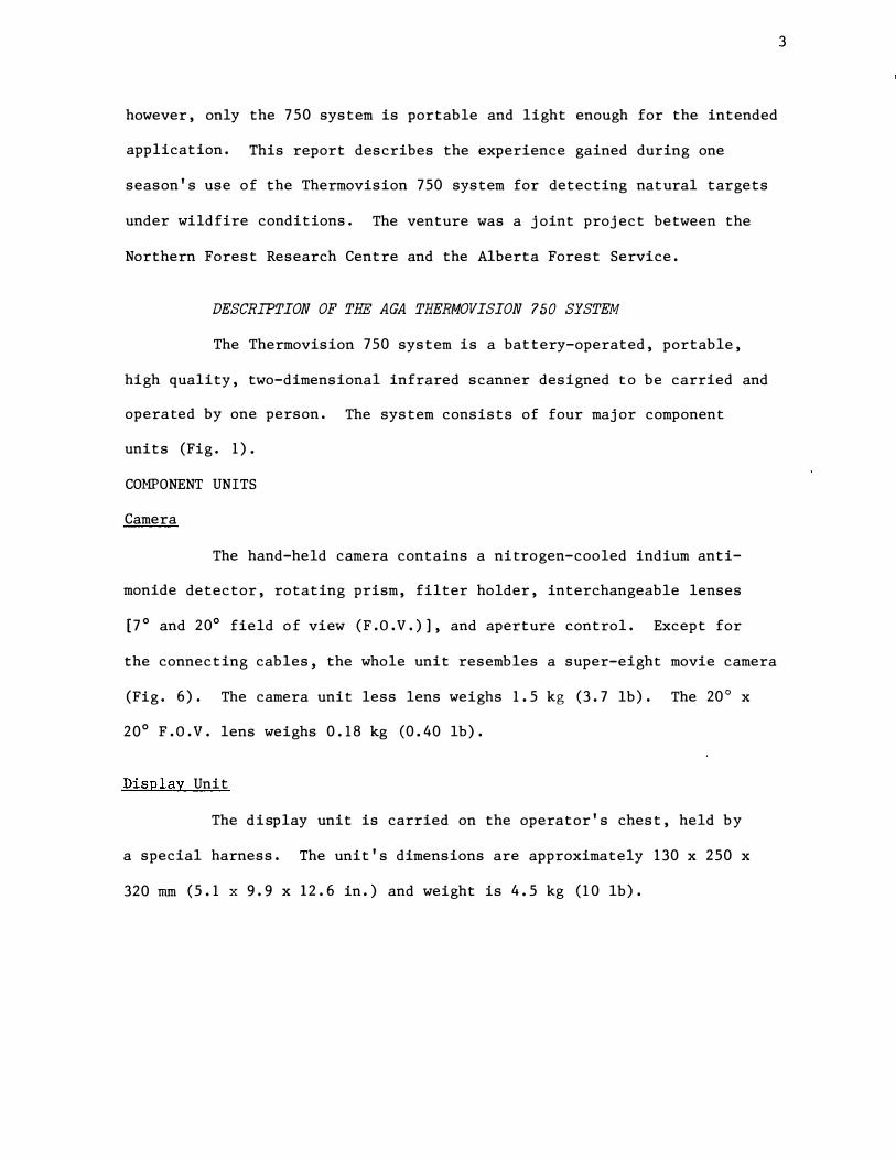
DESCRIPTION OF THE AGA THERMO VISION 750 SYSTEM
The Thermovision 750 system is a battery-operated, portable,
high quality, two-dimensional infrared scanner designed to be carried and
operated by one person. The system consists of four major component
units (Fig. 1).
COMPONENT UNITS
Camera
The hand-held camera contains a nitrogen-cooled indium anti
monide detector, rotating prism, filter holder, interchangeable lenses
f7° and 20° field of view (F. O. V. )] , and aperture control. Except for
the connecting cables, the whole unit resembles a super-eight movie camera
(Fig. 6). The camera unit less lens weighs 1.5 kg (3.7 lb). The 20° x
20° F. O. V. lens weighs 0.18 kg (0.40 lb).
Display Unit
The display unit is carried on the operator's chest, held by
a special harness. The unit's dimensions are approximately 130 x 250 x
320 mm (5.1 x 9. 9 x 12. 6 in. ) and weight is 4.5 kg (10 lb).
3
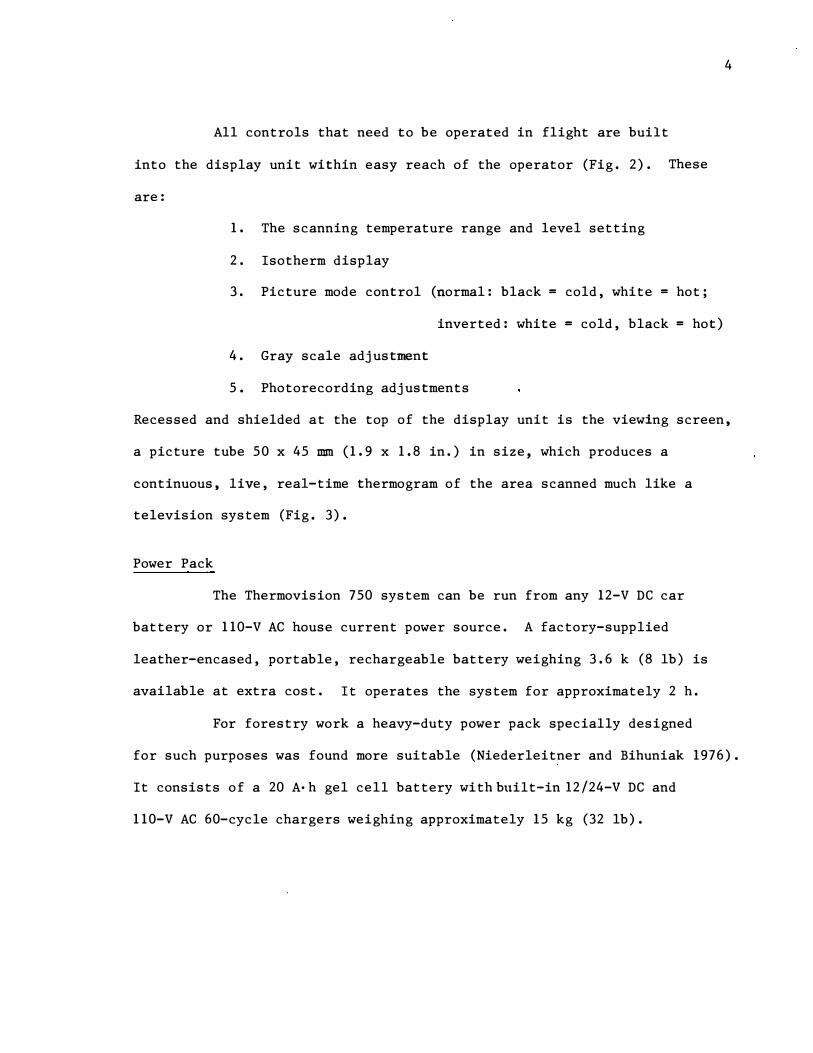
All controls that need to be operated in flight are built
into the display unit within easy reach of the operator (Fig. 2). These
are:
1. The scanning temperature range and level setting
2. Isotherm display
3. Picture mode control (normal: black = cold, white = hot;
inverted: white = cold, black = hot)
4. Gray scale adjustment
5. Photorecording adjustments
4
Recessed and shielded at the top of the display unit is the viewing screen,
a picture tube 50 x 45 mm (1.9 x 1.8 in.) in size, which produces a
continuous, live, real-time thermogram of the area scanned much like a
television system (Fig. 3).
Power Pack
The Thermovision 750 system can be run from any 12-V DC car
battery or 110-V AC house current power source. A factory-supplied
leather-encased, portable, rechargeable battery weighing 3.6 k (8 lb) is
available at extra cost. It operates the system for approximately 2 h.
For forestry work a heavy-duty power pack specially designed
for such purposes was found more suitable (Niederleitner and Bihuniak 1976).
It consists of a 20 A· h gel cell battery with built-in 12/24-V DC and
110-V AC 60-cycle chargers weighing approximately 15 kg (32 lb).

Figure 2. Controls on the display unit, which are located within easy reach of operator. No other controls need to be manipulated during flight.
5
Figure 1. Components of an operational AGA Thermovision 750 system: camera, display unit, and factory-supplied power pack. Nttshown is the photorecording unit. The toilet paper in the operator's hand was used for marking detected hot spots.
Figure 3. Thermogram of a natural hot spot missed by mop-up crew and found from the air. Temperature scanning range setting is 20°C. White hot spot near center of picture is much hotter than background, including the two men in the thermogram. White spot near top is the hot exhaust stack of the helicopter.

Photorecording Unit
A frame containing a flip-away mirror dovetails over the display
tube. By flipping the mirror the picture is reflec�ed from the eye-piece
to a Polaroid camera with Type 87 black and white film pack. The
photorecording frame allows viewing of the thermogram in bright light.
(An adapter to connect a video recording system to the display unit is
available).
PERFORttANCE FACTORS
Scanning Frequency and �etector
The Thermovision 750 system scans in the infrared band between
2.0 and 5.6 microns. Within this range the frequency response can be
selected by means of filters. Heat radiation entering the camera unit
through the germanium or silicon lens is reflected by a rotating scanning
prism onto the indium antimonide detector located on the side of a small
cooling dewar at the back of the camera, generating small pulses of
current which are amplified and rearranged to show on the display screen
as the pictorial thermal analog of the area scanned.
Detector Cooling
6
In order to function, the detector must be cooled to its cryogenic
temperatJre of -196°C (-320°F). This is done by keeping the dewar filled
w ith liquid nitrogen (LN2) (Fig. 5). Loss of all the LN2 from the camera
dewar through spilling or natural evaporation causes the scanner to lose
its temperature resolution temporarily; i t does not damage the camera or
any component.

In its present design the camera can only be pointed downward
to approximately -70° from the horizontal without spilling an appreciable
amount of coolant. Modifications on the dewar cover should make it
possible to operate the camera unit in a vertical position. Normally,
one filling of nitrogen lasts for 2 h.
Resolution
7
According to the manufacturer (AGA Infrared Systems 1973) the
scanner can detect in each angular resolution element a minimum temperature
difference of 0. 2°e (0.36°F). This capability is referred to as tempera
ture resolution. The angular resolution is expressed in mil1iradians,
or mils (one-thousandth of a radian). Thus the smallest area a I-mil
system can resolve from a 300-m (lOOO-ft) elevation is 0. 092 m2 (1 ft2).
The angular resolution for the Thermovision 750 system is given as 1.1 mil
for the 7° F.O. V. lens and 3.3 mil for the 20° F.O. V. lens. The tempera
ture range that can be covered by the scanner is from -200e (-4°F) to
20000e (3632°F). Because of its high temperature and angular resolution
a Thermovision unit flown low can detect ground fires through the slight
rise in temperature in the overlying material caused by warm gases
escaping from the zone actually burning.
Since radiation travels in a straight line the scanner must
have direct line view of the object emitting the radiation. It must be
operated through an open aircraft window, door, or hatch (Fig, 6) and
aimed at the target area in $uch a manner that interference from standing
timber and intervening debris is minimized.
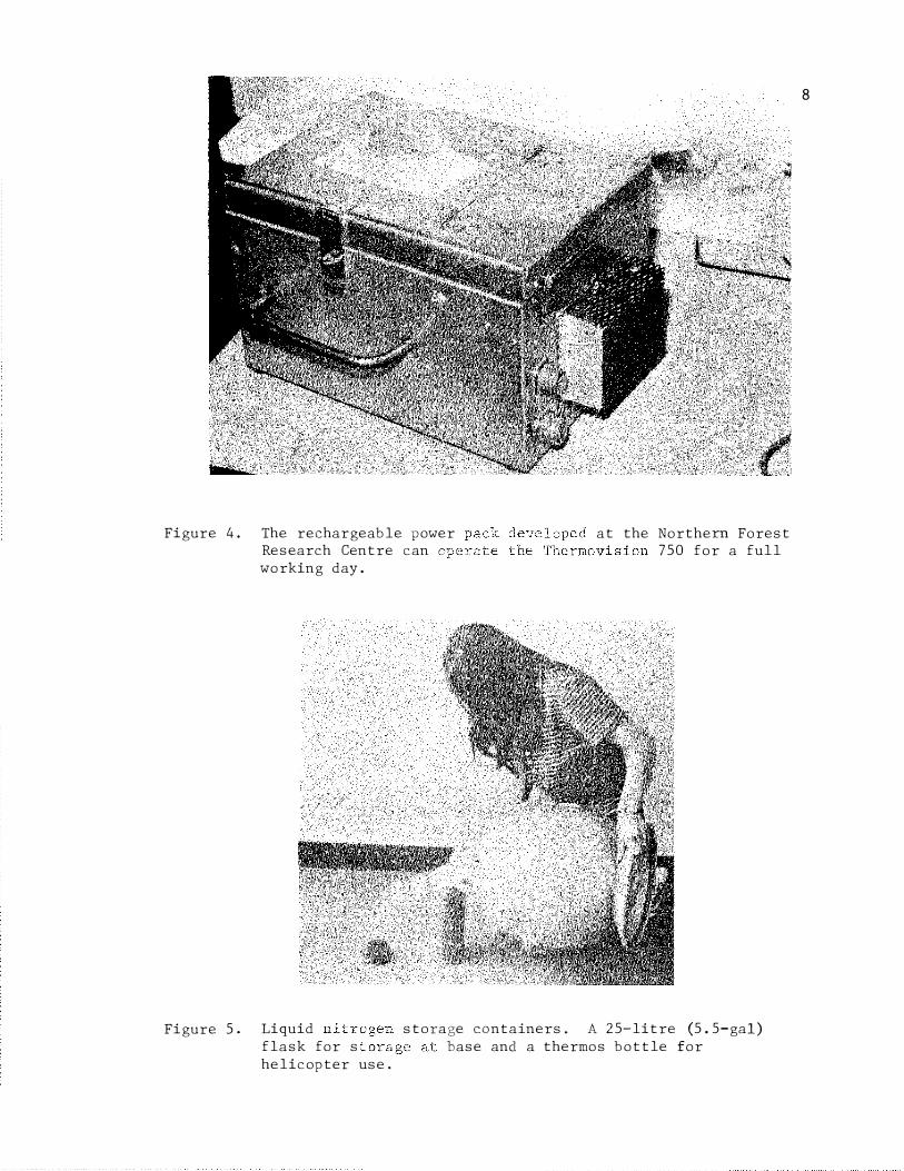
Figure 4. The rechargeable power Research Centre can
at the Northern Forest 750 for a full
Figure 5.
working day.
Liquid flask for s helicopter use.
storage containers. A 25-litre (5.5-gal) base and a thermos bottle for
8
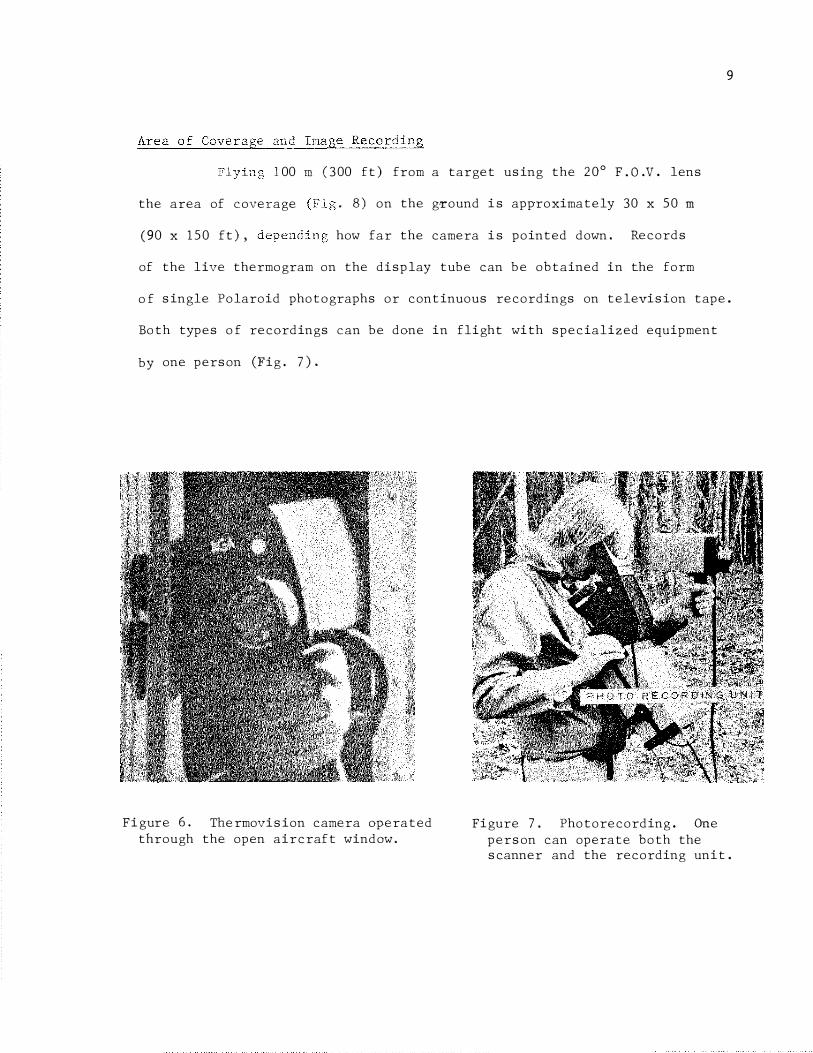
100 m (300 ft) from a target using the 20° F.O.V. lens
the area of coverage
(90 x 150 ft) ,
. 8) on the ground is approximately 30 x 50 m
how far the camera is pointed down. Records
of the live thermogram on the display tube can be obtained in the form
9
o f single Polaroid photographs or continuous recordings on television tape.
Both types of recordings can be done in flight with specialized equipment
by one person (Fig. 7).
Figure 6. Thermovision camera operated through the open aircraft window.
Figure 7. Photorecording. One person can operate both the scanner and the recording unit.
�-= -------
�--
-=-:::::: = -= =---------
-
1m
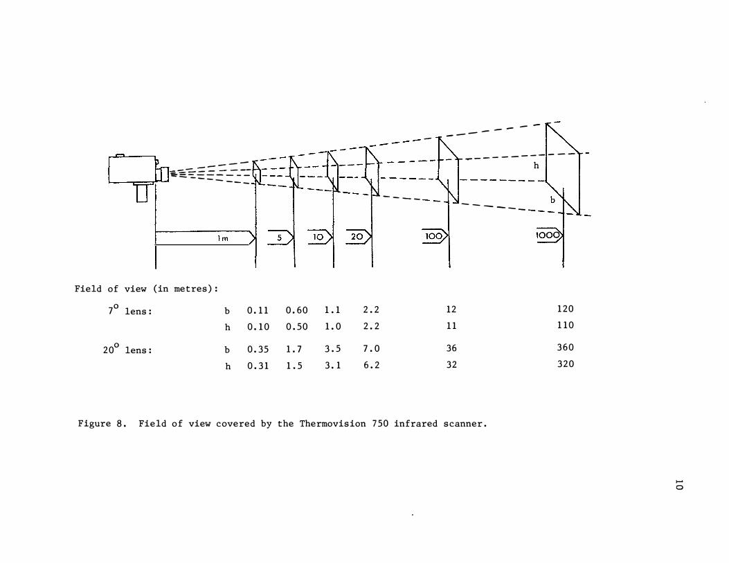
Field of view (in metres):
70 lens: b 0. 11 0. 60
h 0. 10 0. 50
0 20 lens: b 0. 35 1. 7
h 0. 31 1. 5
- ---
1. 1 2. 2
1. 0 2. 2
3. 5 7. 0
3. 1 6. 2
- -
------
12
11
36
32
-----..------
h
--- ---
120
110
360
320
Figure 8. Field of view covered by the Thermovision 750 infrared scanner.
...... o

11
1975 OPERATIONAL TESTS
From the manufacturer's specifications and from our previous
work with the Thermovision 750 we knew that the instrument could pick up
faintly heated targets from a low-flying helicopter. Under ideal
conditions it had picked up forest animals and the faces of fire fighters.
However, a number of questions remained unanswered. Could the scanner,
when used as an integral part of the suppression organization, find
holdover fires that were now eluding detection? Could the AGA Thermovision
750 system be effectively integrated into an ongoing fire suppression
operation without undue disruption? What were the problems in using the
scanner on an operational basis? How and when should the instrument be
used?
We leased an instrument from Agatronics Ltd. of Toronto for a
4-mon span to coincide with the fire season from May to September. The
investigation was carried out jointly with the Alberta Forest Service
which paid half of the instrument rental costs and provided air transpor
tation and whatever assistance was needed at the target area. All work
was done on natural hot spots and within the framework of normal suppression
activity. Since helicopters are the principal fireline aircraft in Alberta,
all work was done by helicopter. Scanning flights were conducted with
whatever aircraft became available and the scanner was removed from the
aircraft immediately after landing in order to release the craft for
other work.
All inspections were done in the presence of the fire boss,
line scout, or forest ranger who observed the screen on the �isplay unit

on the same flight on which he made his visual inspection. Thus the
inspection covered the area of interest to the fire command and line
personnel and eliminated any potential problems in communicating infor
mation for follow-up action.
12
The 1975 fire season was relatively mild and the operational
opportunities to try the scanner were limited. Our first missions were
intended to get the feel of the instrument and to develop suitable
operating and search techniques. Although one man can operate the scanner
we used two and three persons on most flights, mainly to expose as many
people as possible to the scanner and its operation. Forty-three missions
were conducted under vastly differing situations. Aircraft, pilots, and
observers were changed frequently (Table 1). The work in the Whitecourt
Forest in Alberta and in Newfoundland deserves elaboration.
WHITECOURT FOREST
While waiting for calls to work on a fire, a small experiment
was set up to practice with the scanner and to compare the scanner's
capabilities against traditional cold trailing.
A recently burnt windrow at a land clearing project containing
numerous hot spots appeared to be well suited for this purpose (Fig. 9).
A stretch of windrow 150 m (450 ft) long was marked, measured, and cold
trailed systematically in a 1. 5 m (5 ft) grid pattern. Each of the 10
hot spots found was marked for easy visibility from the air. Eight of
the spots produced visible smoke ranging in size from a cigarette's
smoke to the smoke of a small campfire.
Province
Alberta
"
"
"
"
"
"
"
Forest
Whitecourt
"
"
Footner Lake
Slave Lake
Lac La Biche
Edson
Bow-Crow Forest
No. of missions
5
4
3
1
2
1
1
3
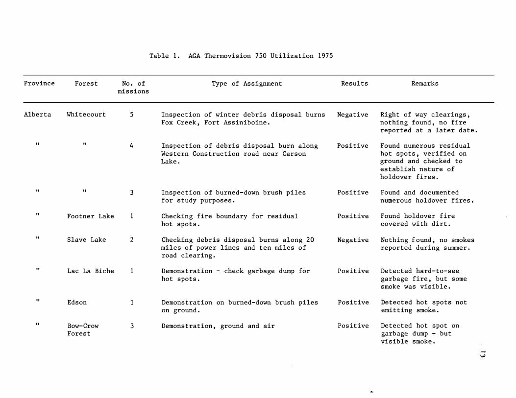
Table 1. AGA Thermovision 750 Utilization 1975
Type of Assignment
Inspection of winter debris disposal burns Fox Creek, Fort Assiniboine.
Inspection of debris disposal burn along Western Construction road near Carson Lake.
Inspection of burned-down brush piles for study purposes.
Checking fire boundary for residual hot spots.
Checking debris disposal burns along 20 miles of power lines and ten miles of road clearing.
Demonstration - check garbage dump for hot spots.
Demonstration on burned-down brush piles on ground.
Demonstration, ground and air
Results
Negative
Positive
Positive
Positive
Negative
Positive
Positive
Positive
Remarks
Right of way clearings, nothing found, no fire reported at a later date.
Found numerous residual hot spots, verified on ground and checked to establish nature of holdover fires.
Found and documented numerous holdover fires.
Found holdover fire covered with dirt.
Nothing f ound, no smokes reported during summer.
Detected hard-to-see garbage fire, but some smoke was visible.
Detected hot spots not emitting smoke.
Detected hot spot on garbage dump - but visible smoke.

Province
Alberta
Forest
Rocky Mtn. House
Newfound- Exploits land
p�berta Forestry Training School, Hinton
TOTAL
No. of missions
1
15
7
43
Type of Assignment
Demonstration on ground inspecting burneddown brush piles.
Inspection of 64 km (40 miles) of fireline for hot spots.
Inspection of 24-ha (60-acre) prescribed burn as part of t raining for 15 fire overhead t rainees and two instructors.
Results
Positive
Positive
Positive
Remarks
Detected hot spots not emitting smoke. Took video recording off scanner screen.
Located some 20 non smoking hot spots each morning to keep 140 men and 5 copters busy.
Fire contained numerous hot spots, many still smoking. No hot spots outside fireline.

a. b.
c.
Figure 9. Thermovision 750 test on a burnt windrow hot spots.
a. Black and vlhite infrared film of of windrow.
b. of same area from 33 m ( 00 ft) altitude.
c. from same position after /
d. from 50 m (150 ft) altitude of same area and with scanning sensit reduced to t spots and block background. The three evenly at lower are reference markers (0. 57-litre tin cans 2 charcoal briquettes).
15
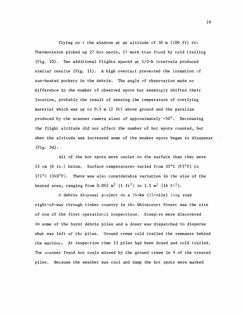
Flying ov- r the windrow at an altitude of 30 m (l00 ft) the
Thermovision picked up 27 hot spots, 17 more than found by cold trailing
(Fig. 10). Two additional flights spaced at 1/2-h intervals produced
similar results (Fig. 11). A high overcast prevented the formation of
sun-heated pockets in the debris. The angle of observation made no
difference in the number of observed spots but seemingly shifted their
location, probably the result of sensing the temperature of overlying
material which was up to 0. 5 m (2 ft) above ground and the parallax
produced by t he scanner camera slant of approximately -50°. Decreasing
16
the flight altitude did not affect the number of hot spots counted, but
when the altitude was increased some of the weaker spots began to disappear
(Fig. 3d).
All of the hot spots were cooler on the surface than they were
15 cm (6 in.) below. Surface temperatures varied from 35°C �5°F) to
171°C (340°F). There was also considerable variation in the size of the
heated area, ranging from 0. 092 m2 (1 ft2) to 1.5 m2 (16 ft2).
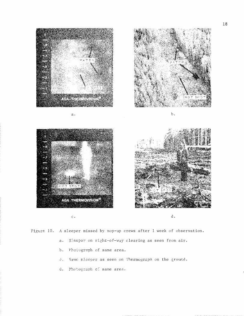
A debris di.3posal project on a 24-km (IS-mile) long road
right-of-way through timber country in the Whitecourt Forest was the site
of one of the first operational inspections. Sleepers were discovered
in some of the burnt debris piles and a dozer was dispatched to disperse
what was left of the piles. Ground crews cold trailed the remnants behind
the machine. At inspection time 13 piles had been dozed and cold trailed.
The scanner found hot coals missed by the ground crews in 9 of the treated
piles. Because the weather was cool and damp the hot spots were marked

for further inspection and left to go out by themselves. A lone spot
lasted more than 1 wk (Figs. lOa, b, c, d). It was then put out to
avoid further inspection trips.
NEWFOUNDLAND
The 11 OOO-ha (27 OOO-acre) "Exploits" fire in Newfoundland
offered the opportunity to apply the scanner in support of a major mop-up
operation. Some 64 km (40 miles) of irregular and winding fire boundary,
interspersed with spot fires outside the fireline and incomplete burns,
required patrolling.
Almost every day, sleepers located well inside and along the
perimeter of the fire, flaring up in high winds toward noon, threatened
17
to escape the thinly spread suppression forces. A means of detecting the
sleepers in their dormant stage earlier in the day when they could be
drowned out easily was needed. Each day the scanner, taken along on the
fire boss's morning inspection flight, detected numerous hot spots.
Approximately 20 (enough to keep the suppression crews busy for one day)
were flagged with calculator paper, and the suppression crews following in
other helicopters were directed to them by forestry radios. The paper
flagging not only helped the suppression crews to locate the hot spots,
but when ripped into shreds after the fire was extinguished, served as
reference for subsequent inspection flights.
After a few missions a pattern of operating and search techniques
evolved. Because most operators are right-handed, we pointed the camera
a. b.
c. d.
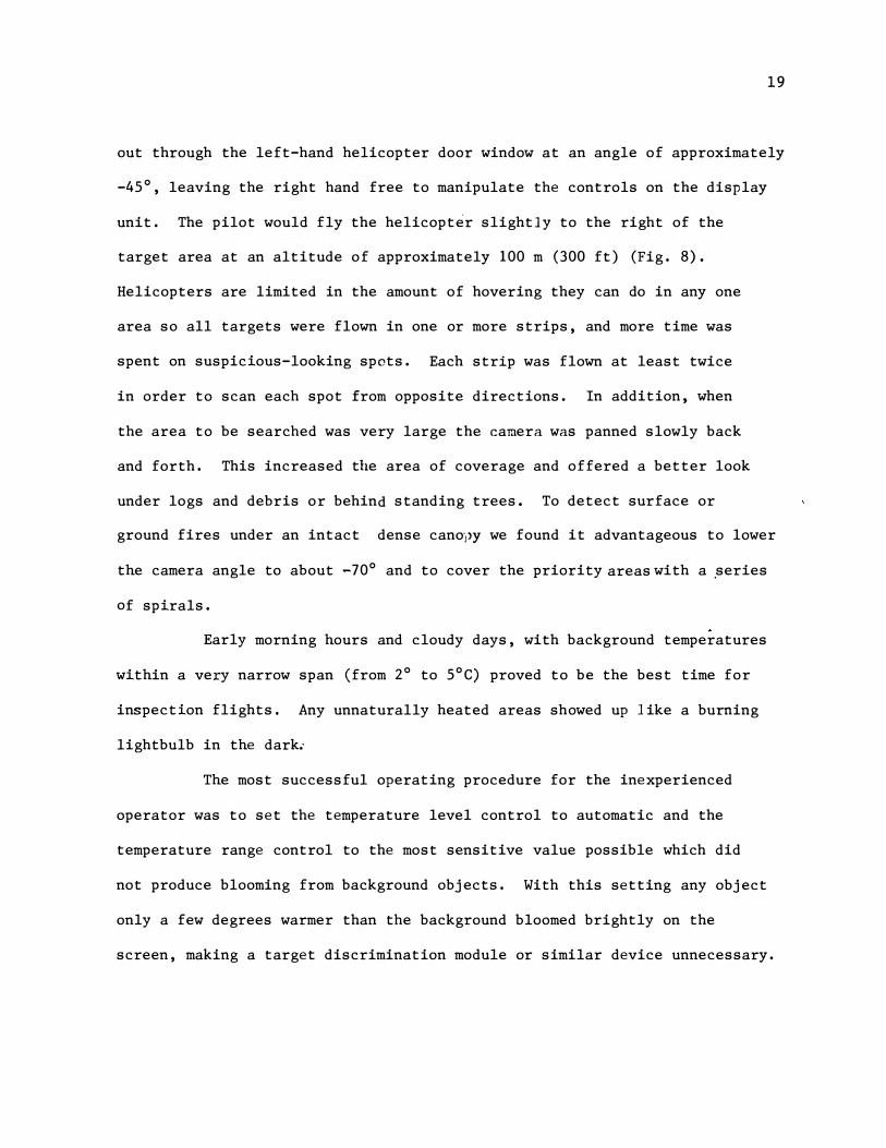
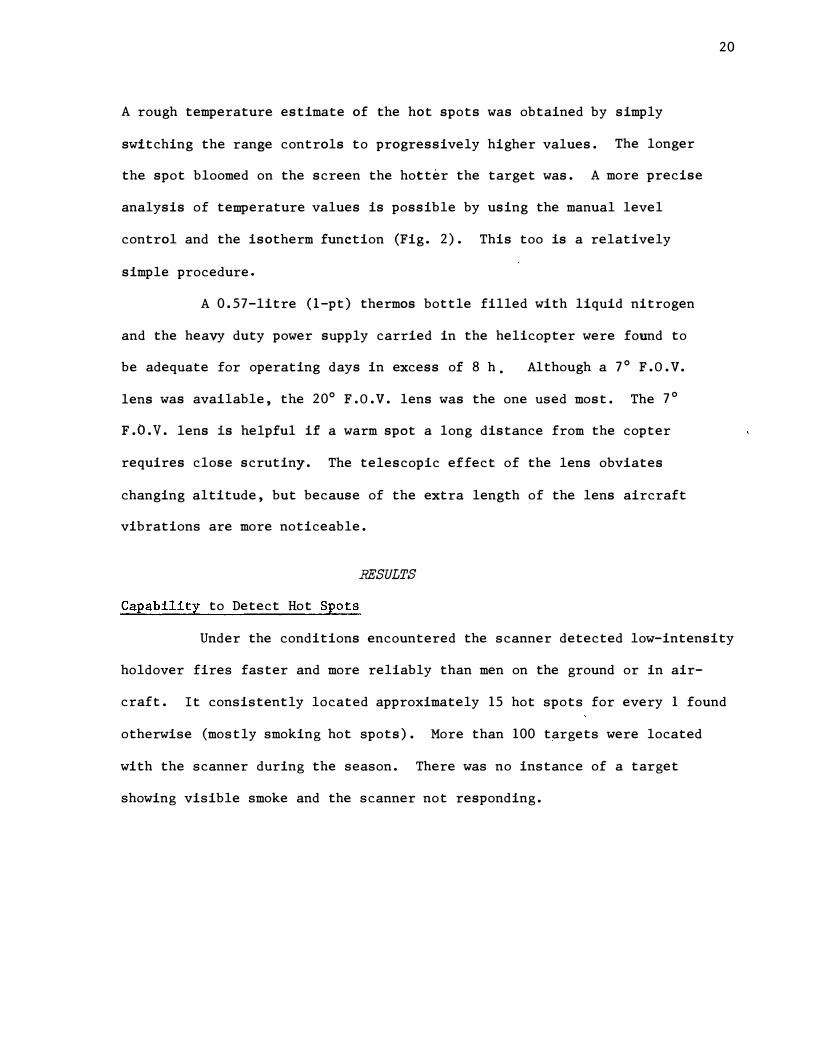
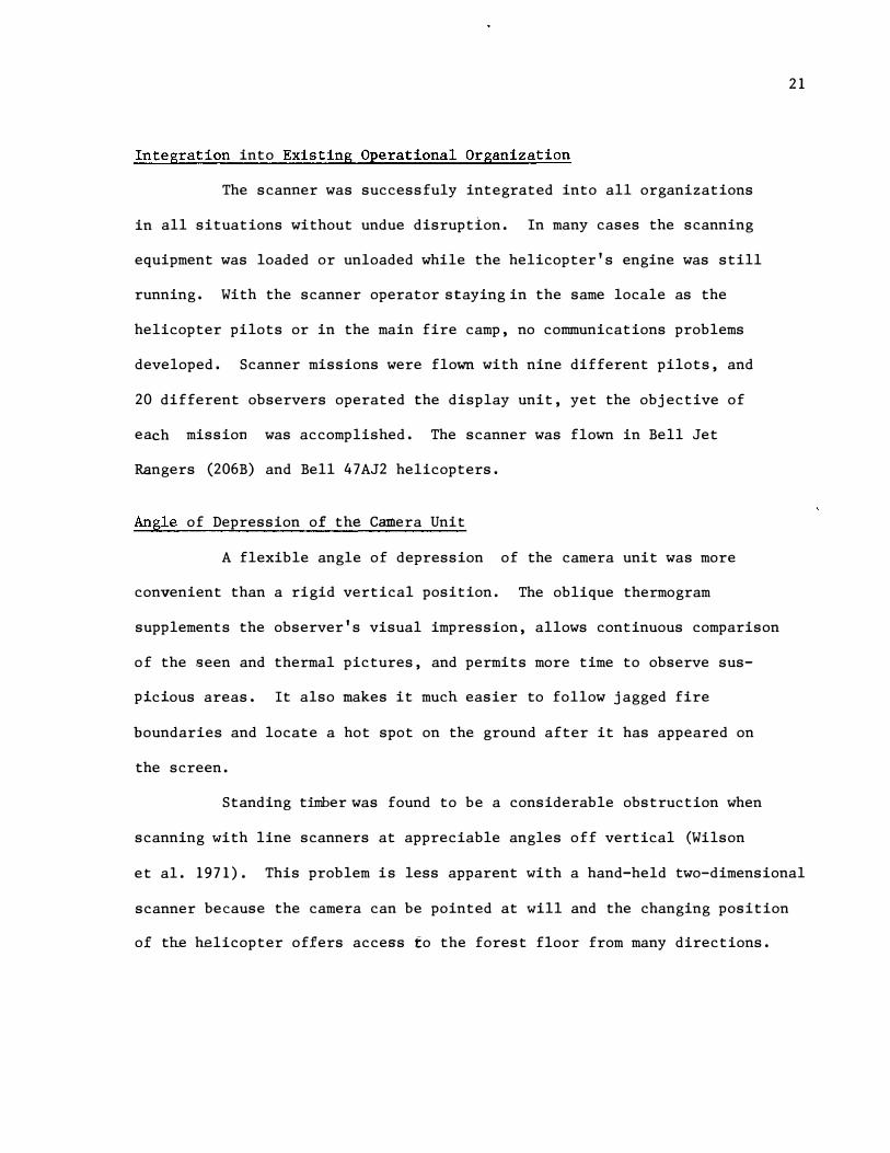
10. A sleeper missed mop-up crews after 1 week of observation.
a.
h.
on ri clearing as seen from air.
of same area.
as seen on on the
same area.
18
19
out through the left-hand helicopter door window at an angle of approximately
-45°, leaving the right hand free to manipulate the controls on the display
unit. The pilot would fly the helicopter slightly to the right of the
target area at an altitude of approximately 100 m (300 ft) (Fig. 8).
Helicopters are limited in the amount of hovering they can do in any one
area so all targets were flown in one or more strips, and more time was
spent on suspicious-looking spots. Each strip was flown at least twice
in order to scan each spot from opposite directions. In addition, when
the area to be searched was very large the camera was panned slowly back
and forth. This increased the area of coverage and offered a better look
under logs and debris or behind standing trees. To detect surface or
ground fires under an intact dense cano'J)Y we found it advantageous to lower
the camera angle to about _70° and to cover the priority areas with a ,series
of spirals.
Early morning hours and cloudy days, with background temperatures
within a very narrow span (from 2° to 5°C) proved to be the best time for
inspection flights. Any unnaturally heated areas showed up l ike a burning
light bulb in the dark..
The most successful operating procedure for the inexperienced
operator was to set the temperature level control to automatic and the
temperature range control to the most sensitive value possible which did
not produce blooming from background objects. With this setting any object
only a few degrees warmer than the background bloomed brightly on the
screen, making a target discrimination module or similar device unnecessary.
A rough temperature estimate of the hot spots was obtained by simply
switching the range controls to progressively higher values. The longer
the spot bloomed on the screen the hotter the target was. A more precise
analysis of temperature values is possible by using the manual level
control and the isotherm function (Fig. 2). This too is a relatively
simple procedure.
A 0. 57-litre (l-pt) thermos bottle filled with liquid nitrogen
and the heavy duty power supply carried in the helicopter were found to
be adequate for operating days in excess of 8 h . Although a 7° F. O. V.
lens was available, the 20° F. O. V. lens was the one used most. The 7°
F. O. V. lens is helpful if a warm spot a long distance from the copter
requires close scrutiny. The telescopic effect of the lens obviates
changing altitude, but because of the extra length of the lens aircraft
vibrations are more noticeable.
RESULTS
Capability to Detect Hot Spots
20
Under the conditions encountered the scanner detected low-intensity
holdover fires faster and more reliably than men on the ground or in air
craft. It consistently located approximately 15 hot spots for every 1 found
otherwise (mostly smoking hot spots). More than 100 targets were located
with the scanner during the season. There was no instance of a target
showing visible smoke and the scanner not responding.
Integration into Existing Operational Organization
The scanner was successfuly integrated into all organizations
in all situations without undue disruption. In many cases the scanning
equipment was loaded or unloaded while the helicopter's engine was still
running. With the scanner operator staying in the same locale as the
helicopter pilots or in the main fire camp, no communications problems
developed. Scanner missions were flown with nine different pilots, and
20 different observers operated the display unit, yet the objective of
each mission was accomplished. The scanner was flown in Bell Jet
Rangers (206B) and Bell 47AJ2 helicopters.
Angle of Depression of the Camera Unit
A flexible angle of depression of the camera unit was more
convenient than a rigid vertical position. The oblique thermogram
supplements the observer's visual impression, allows continuous comparison
of the seen and thermal pictures, and permits more time to observe sus
picious areas. It also makes it much easier to follow jagged fire
boundaries and locate a hot spot on the ground after it has appeared on
the screen.
Standing timber was found to be a considerable obstruction when
scanning with line scanners at appreciable angles off vertical (Wilson
21
et al. 1971). This problem is less apparent with a hand-held two-dimensional
scanner because the camera can be pointed at will and the changing position
of the helicopter offers access to the forest floor from many directions.
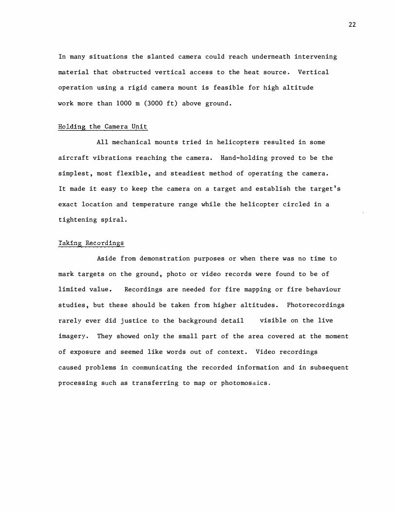
In many situations the slanted camera could reach underneath intervening
material that obstructed vertical access to the heat source. Vertical
operation using a rigid camera mount is feasible for high altitude
work more than 1000 m (3000 ft) above ground.
Holding the Camera Unit
All mechanical mounts tried in helicopters resulted in some
aircraft vibrations reaching the camera. Hand-holding proved to be the
simplest, most flexible, and steadiest method of operating the camera.
It made it easy to keep the camera on a target and establish the target's
exact location and temperature range while the helicopter circled in a
tightening spiral.
Taking Recordings
Aside from demonstration purposes or when there was no time to
mark targets on the ground, photo or video records were found to be of
limited value. Recordings are needed for fire mapping or fire behaviour
studies, but these should be taken from higher altitudes. Photorecordings
rarely ever did justice to the background detail visible on the live
imagery. They showed only the small part of the area covered at the moment
of exposure and seemed like words out of context. Video recordings
caused problems in communicating the recorded information and in subsequent
processing such as transferring to map or photomosaics.
22

a. b.
Figure 1 1 . Video recordings.
a. Video recording of thermogram showing refuse dump with hot
spots.
b. Video recording of same area from slightly different angle.
Flying Height
To locate and mark low-intensity hot spots precisely or to
under-fly clouds the scanner must be flown as low as possible, yet high
enough to cover enough territory to make the search meaningful. Most work
in 1 975 was done at an altitude of 100 m (300 ft). Flying at higher
altitudes resulted in weak targets fading out and clusters of targets
located close together fusing into one blob on the imagery.
Hot or flaming targets can be sensed by the scanner from great
distances. For instance, a weak surface fire in a dense timber stand
obscured by low-lying smoke more than 1000 m (3000 ft) away could be
clearly seen on the scanner screen, yet the airtanker group flying low
over the area to bomb the fire could neither see the flames nor observe
the effect of their drops through the smoke.
23

Figure 12. Fire mapping. Oblique thermogram of 24-ha (60-acre) slash disposal project taken from 650-m (2000-ft) altitude 2 days after burning with little visible smoke but much smoldering debris. All white areas are hotter than the normal background temperature of 6°C (43°F).
Coolant for the Detector
A 25-litre (5. 5-gal) flask of LN2 was kept ready throughout the
season. One filling, costing approximately $50, lasted for 1 mono
A 0. 57-litre (l-pt) thermos bottle was carried in the copter from which
the camera dewar was filled in flight as required. LN2 is available at
most larger centers and is acceptable as air freight shipment.
24

Operating Reliability
No breakdown of equipment was encountered during the 4-mon
season, nor was any adjustment or servicing of any component required.
The Scanner was shipped to numerous fire camps in Alberta and Newfoundland
by public transporation, truck, car, and aircraft. At fire camps serviced
by helicopter the scanner was exposed to heavy dust.
False Alarms and Interference
The Thermovision 750 system was equipped with the optionally
available anti-solar reflection filter. This filter reduces but does not
totally eliminate reflected sunlight. On rare occasions sun reflections
off water bodies could be observed but were never mistaken for a fire.
No instances of interference by static, atmospheric disturbances,
lightning, radio transmissions, or any other source were observed. Clouds,
fog, or high relative humidity have little influence on the scanner's
performance because it is operated very close to the target. The scanner
was not bothered by picture tube saturations, afterglow, ghosts, trails,
distortion or synchronization problems, excessive response lag, or similar
occurrences common with television systems.
Resolution and Image
25
Because the thermal imagery consists of only 70 lines with 100
picture elements per line, it appears coarse when compared to a photograph.
Yet, because each picture element is fairly large, the operator can quickly
spot the few picture elements blooming out when a hot spot is found. The
scanner's imagery is not susceptible to distortions common with line scanners.
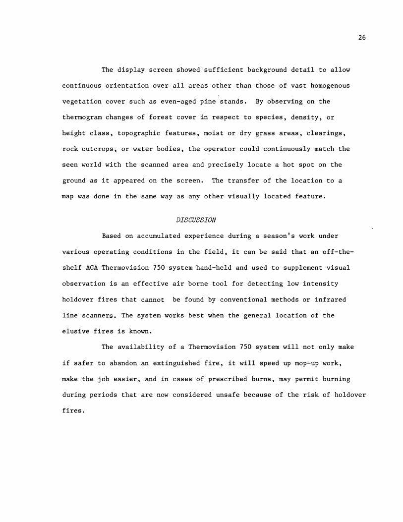
The display screen showed sufficient background detail to allow
continuous orientation over all areas other than those of vast homogenous
vegetation cover such as even-aged pine stands. By observing on the
thermogram changes of forest cover in respect to species, density, or
height class, topographic features, moist or dry grass areas, clearings,
rock outcrops, or water bodies, the operator could continuously match the
seen world with the scanned area and precisely locate a hot spot on the
ground as it appeared on the screen. The transfer of the location to a
map was done in the same way as any other visually located feature.
DISCUSSION
Based on accumulated experience during a season's work under
various operating conditions in the field, it can be said that an off-the
shelf AGA Thermovision 750 system hand-held and used to supplement visual
observation is an effective air borne tool for detecting low intensity
holdover fires that cannot be found by conventional methods or infrared
line scanners. The system works best when the general location of the
elusive fires is known.
The availability of a Thermovision 750 system will not only make
if safer to abandon an extinguished fire, it will speed up mop-up work,
26
make the job easier, and in cases of prescribed burns, may permit burning
during periods that are now considered unsafe because of the risk of holdover
fires.

Although no fires were mapped with the Thermovision 750 system
[large fires were observed on the display screen and a 24-ha (60-acre)
27
fire recorded] the instrument has the potential to collect and record fire
intelligence through heavy smoke. By providing information on the perimeters,
intensity, behaviour, and rate of spread of fires in smoke-obscurred areas,
the Thermovision 750 seems to be an ideal mate for fire mapping operations
based on infrared photography taken on site.
Airtanker and helitanker operations on large fires are usually
condemned to idleness during the early morning hours -- when they could
be most effective -- because either the lack of visible flames and smoke
or the presence of obscuring smoke prevents detection of hot spots. A
lead-in plane (probably a helicopter) with a Thermovision should be
able to direct water or retardant drops more effectively during such
periods as well as gain a better overview of retardant drop concentrations
by using the scanner's capability to isolate cooled areas.
The Thermovision 750 system is well suited for use on wildfires
by fire line personnel because of its simple operation and its real time
clear-cut imagery that eliminates the need for handling or interpretation
by third parties.
Radio links to and from the scanner aircraft can be used at all
times, since the Thermovision is not, unlike most line scanners, affected
by radio transmissions.

The AGA Thermovision 750 system is a precision instrument yet
rugged enough to be taken to the fireline. It survived a season of rough
fieldwork with no damage. Since the system is fully portable it can be
quickly taken in and out of helicopters, releasing the helicopter for other
work whenever required.
Cost for a complete Thermovision 750 system is estimated to be
approximately $35 000. The system is manufactured by AGA Infrared Systems
AB S-181 81 LIDINGO, SWEDEN, TELEX 17781 AGALIDS and distributed by:
AGATRONICS LTD. 41 HORNER AVE. , UNIT 5, TORONTO 18 TELEPHONE 252-4691
The question of cost-benefit is difficult to answer. Assuming
that the Thermovision has a life of 5 yr, the annual cost is $7 000 plus
miscellaneous expenses. At our arrival in Newfoundland the Exploits fire
had tied down five Bell 206B helicopters and some 140 men who had been
28
playing cat and mouse with sleepers for more than three weeks. An operation
of this type costs a good $10 000 per day. Would it be too much to assume
that had the scanner been available from the start it would have saved
four operating days and paid for itself?
RECOMMENDATIONS
The AGA Thermovision can and should initially be used in the
field as it comes from the factory. If the scanner is to be used for low-
intensity fire detection and fire mapping the following items are required:
1. Camera unit
2. Display unit
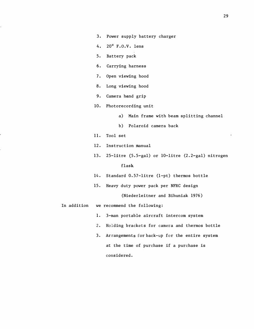
In addition
3. Power supply battery charger
4. 20° F.O.V. lens
5. Battery pack
6. Carrying harness
7. Open viewing hood
8. Long viewing hood
9. Camera hand grip
10. Photorecording unit
a) Main frame with beam splitting channel
b) Polaroid camera back
11. Tool set
12. Instruction manual
29
13. 25-litre (5.5-gal) or 10-litre (2. 2-gal) nitrogen
flask
14. Standard 0.57-litre (l-pt) thermos bottle
15. Heavy duty power pack per NFRC design
(Niederleitner and Bihuniak 1976)
we recommend the following:
1. 3-man portable aircraft intercom system
2. Holding bracke ts for camera and thermos bottle
3. Arrangements for back-up for the entire system
at the time of purchase if a purchase is
considered.
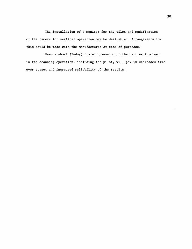
The installation of a monitor for the pilot and modification
of the camera for vertical operation may be desirable. Arrangements for
this could be made with the manufacturer at time of purchase.
Even a short (2-day) training session of the parties involved
in the scanning operation, including the pilot, will pay in decreased time
over target and increased reliability of the results.
30
REFERENCES
AGA Infrared Systems AB. 1973. AGA Thermovision 750. Portable,
lightweight, infrared camera system for live presentation of
temperature distribution on fixed or moving objects.
Publications No. 556 402, 556 408, 556 409, 556 410, 556 416,
556 424, (In Canada: Agatronics Ltd., Horner Ave., Unit 5,
Toronto, Ont., M8Z 4X4.)
Anonymous. 1974. Infrared equipment. Products and Services Section,
Aviation Week Marketing Directory. Aviat. Week Space Techno1.
101 (25): 151. Dec 23/74.
Barnes Engineering Co. 1970. Model 15-211 Airborne Fire Spotter.
30 Commerce Rd., Stamford, Conn. 06904, U.S.A. Bull. 15-211B.
7 pp., ill.
Computing Devices of Canada Ltd. [1965] . Firemapper, Infrared forest
fire mapping and detection system. P.O. Box 508, Ottawa 4,
Onto Brochure. 12 pp., ill.
Hirsch, S.N., R.L. Bjornsen, F.H. Madden, and R. Wilson. 1968. Project
Fire Scan fire mapping final report April 1962 to December 1966.
U.S. Dep. Agric., For. Serv., Intermountain For. Range Exp.
Stn. Res. Pap. INT-49. 49 pp., ill.
Hirsch, S.N., R.F. Kruckeberg, F.H. Madden. 1971. The bispectral forest
fire detection system. pp. 2253-2272 (Vol. 3) In Proc. 7th
Int. Symp. Remote Sense Environ. May 17-21, 1971. Ann Arbor,
Michigan.
31

Kourtz, P. and W.E. Pinson. 1975. Forest fire mapping using an 8-13
micron pyroelectric vidicon. Environ. Can., For. Serv., For.
Fire Res. Inst. Ottawa, Onto Inf. Rep. FF-X-52.
Kruckeberg, R.F. 1971. No smoke needed. U.S. Dep. Agric., For. Servo
Fire Control Notes 32 (2) : 9-11.
Niederleitner, J. and P. Bihuniak. 1976. A heavy-duty 12-Volt DC power
pack to operate airborne remote sensing systems. Environ. Can.,
Environ. Manage. Serv., North. For. Res. Cent. Edmonton, Alta.
Inf. Rep. NOR-X-147.
Pinson, W.E. 1975. Final Report: 1) The role of a Pbs-Pbo infrared
vidicon in detecting and mapping forest fires. 2) Comparison
of its performance with that of a pyroelectric vidicon. Environ.
Can., For. Serv. , For. Fire Res. Inst. Ottawa, Onto
Wilson, R. A. , S. N. Hirsch, F.H. Madden and J. Losensky. 1971. Airborne
infrared forest fire detection system: Final Report. U. S. Dep.
Agric. , For. Serv., Intermountain For. Range Exp. Stn., North.
For. Fire Lab. Missoula, Mont. Res. Pap INT-93.
32
APPENDIX
REVIEW OF CURRENT EQUIPMENT AND TECHNIQUES
GROUND APPLICATIONS
Cold Trailing
The best known technique of finding low intensity hot spots is
cold trailing. This method requires the men to feel every suspicious
looking spot with their bare hands.
Hand-held Infrared Detection Devices
A number of hand-held infrared sensors have been tried to
simplify cold trailing. These instruments are basically radio meters that
give an audible warning when pointed at a heat source exceeding a certain
radiation intensity value. Some of the models field-tested were the
DeHaviland Hotspotter, the Spar Aerospace Hotspotter, the Williamson
Model 1207 Fire Detector, and an infrared heat detector Model 1175-1-1
of unknown manufacture. None of them were acceptable, mainly because
of the instrument's narrow angle of coverage and relatively poor heat
sensitivity.
33
AIRBORNE APPLICATIONS
Infrared Line Scanners1 Designed for Forest Fire Detection and/or
Fire Mapping
The United States Forest Service under Project Fire Scan
developed and experimented with several infrared scanners that can
detect forest fires from their high intensity heat radiation through
heavy smoke, independent of visible light (Wilson et al. 1971).
The Barnes Airborne Fire Spotter (Kruckeberg 1971, Anon. 1970):
This is the simplest, cheapest, and most popular scanner (over 40 units
were commercially produced) that came out of the project. Instead of
producing imagery or recordings of the scanned terrain, the scanner has
a bank of lights that indicate in which scanning sector a high radiant
energy source is located. By design this scanner should detect a
0. 092-m2 (1-ft2) size target in the 600°C (1112°F) range from 750 m
(2000 ft) altitude, but will not respond to the low surface heat produced
by many holdover fires. The initial popularity of the Barnes spotter
has declined because of the unit's susceptibility to frequent false alarms.
Line scanners record only one narrow strip of terrain at right angles
to the aircraft axis at a time. The scanner depends upon the uniform
forward movement of the aircraft to compile a two-dimensional picture
by placing each newly scanned line ahead of the previous scan line
similar to a continuous strip camera. In turbulent air or if the film
transport is not perfectly synchronized with the aircraft speed the
imagery can be badly distorted. This is the reason why line scanners
cannot produce any meaningful imagery from a stationary position or
from a meandering helicopter.
34
Availability: Originally an off-the-shelf item, but at this time out
of production.
Cost: (in Canada, 1972) $3500
H.R.B. Singer Reconofax XI (Hirsch et ale 1968): This high quality
line scanner, used mainly with a Polaroid recording unit, is basically
a fire mapping tool. If flown low it should pick up fair-sized holdover
fires, but we have no information to suggest that the Reconofax XI is
capable of detecting low-intensity sleeper fires.
Availability: Made to customer's order.
Cost: (in U.S.A., 1972) approx. $100 000
Bispectral System (Wilson et al.1971): The bispectral system is
the most sophisticated infrared line scanning system developed through
Project Fire Scan. It is a modified Texas Instrument, RS7 line scanner
operating on two channels, designed to detect a 0.092-m2 (l-ft2) 600°C
(1112°F) target from 5000 m (15 000 ft) altitude, equipped with near-real
time in-flight printout capability and a target discrimination module.
35
It is suitable for fire detection flights over large areas as well as for
mapping. However, even this scanner is of questionable value as a holdover
fire detection tool, mainly because it requires the high radiant energy
pulse as emitted by glowing material in direct line of sight to trigger
the target discrimination module. In a paper summarizing the progress of
Project Fire Scan, Hirsch et ale (1971) stated that "Fir� too small to
print on the image can be identified and located by ground crews."
Availability: Made to customer's order.
Cost: (in U.S.A., 1972) approx. $140 000
Fire Mapper: A Canadian manufacturer, Computing Devices of Canada,
produced this infrared scanner which was tested in Ontario. As the
instrument's name implies, the unit was meant to map going wildfires
through smoke and had some fire detection capability (Computing Devices
of Canada Ltd. 1965). The unit did not meet Ontario Forest Service
expectations and is apparently not in operational use.
Availability: Not known.
Cost: (in 1972) approx. $40 000
Other Thermal Mappers
Many companies manufacture thermal line scanners and thermal
mappers (Anon. 1974) capable of mapping or collecting information from
going wildfires through smoke, but in order to use them for fire detection
purposes, further development and modificiations similar to the work done
under Project Fire Scan would be required.
Other Remote Sensing Systems or Devices
Various optical and electronic devices such as night vision
goggles, infrared fire detector telescopes, and special filters for
binoculars or spectacles have been tried as aids in fire detection with
little success.
Some television systems are sensitive to radiation in the near
infrared and the infrared spectrum. Recent tests with infrared television
36
systems (Kourtz 1975, Kourtz and Pinson 1975) did meet with some success
in imaging high radiant energy targets [a cluster of five 60-cm (2-ft)
diameter charcoal buckets] at altitudes up to 1300 m (4000 ft) with a 10°
field of view lens. While these tests show that infrared television
systems have some potential no evidence was presented to support the
conclusion that sleeper or holdover fires could be detected.
37