holmium surgical laser operator's manual · orthopedics, ent, gynecology, and general surgery...
TRANSCRIPT

Holmium Surgical LaserOperator's Manual
® TM
Lumenis Pulse 120H UM-10012510 Rev. F Page 2
This manual is copyrighted with all rights reserved. Under copyright laws,this manual may not be copied in whole or in part or reproduced in anyother media without the express written permission of Lumenis. Permittedcopies must carry the same proprietary and copyright notices as wereaffixed to the original. Under the law, copying includes translation intoanother language.Please note that while every effort has been made to ensure that the datagiven in this document is accurate, the information, figures, illustrations,tables, specifications, and schematics contained herein are subject tochange without notice.Lumenis, the Lumenis Logo, Lumenis Pulse 120H, SlimLine, Xpeeda andMoses are trademarks or registered trademarks of Lumenis.
CAUTION:In the USA: Federal law restricts this device to sale by or on the order of a physician.
Copyright © Lumenis Ltd.Catalog Part Number: UM-10012510March 2017Revision F
Directive 2012/19/EU on Waste Electrical and Electronic Equipment(WEEE)In accordance with Directive 2012/19/EU on Waste Electrical andElectronic Equipment (WEEE), any item which is marked with thecrossed-out wheelie bin symbol must not be disposed of as unsortedmunicipal waste, but segregated from other waste types for eventualtreatment and recovery at an approved recycling facility.By returning waste electrical and electronic equipment via the correctsegregated disposal channel, users can ensure the environmentally soundtreatment and disposal of the waste equipment, thereby reducing thepotential for any environmental or health risks that could arise as a resultof incorrect disposal. Lumenis provides web-based collection, recycling and reportingarrangements to the business end-user for equipment marked with thecrossed-out wheelie bin. Please visit http://www.lumenis.com/Service-Support/Recycle to under-stand what arrangements Lumenis has made in each EU Member State.
Lumenis Pulse 120H UM-10012510 Rev. F Page 3
Authorized Representative in the European Community:Lumenis (Germany) GmbHHeinrich-Hertz-Strasse 3D-63303 Dreieich-DreieichenhainGermanyTel: +49 (0) 6103.8335.0
Manufactured by Lumenis Ltd.Yokneam Industrial park6 Hakidma StreetP.O.B. 240Yokneam 2069204, IsraelTel: +972.4.959.9000Fax: +972.4.959.9050www.Lumenis.com
0483
EC REP

Lumenis Pulse 120H UM-10012510 Rev. F Page 4
Introduction .................................................................................................................. 7Manual Conventions .................................................................................... 8System Description and Main Features ....................................................... 9Component Checklist ................................................................................. 11
Holmium Laser Theory of Operation ........................................................................ 12Laser Power Parameters ........................................................................... 12Moses Capability ........................................................................................ 13
Safety .......................................................................................................................... 15Introduction ................................................................................................ 15Optical Hazards .......................................................................................... 15Electrical Hazards ...................................................................................... 17Fire Hazards ............................................................................................... 18Additional Safety Considerations ............................................................... 18Protecting Non-Target Tissues .................................................................. 19Safety Indicators ........................................................................................ 20Warning, Certification and Identification Labels ......................................... 21
Clinical Guide ............................................................................................................. 25Effect on Soft Tissue .................................................................................. 25Effects on Stones ....................................................................................... 26Indications for Use ..................................................................................... 27Contraindications ....................................................................................... 27Warnings and Precautions ......................................................................... 28Complications ............................................................................................. 29Detailed Indications for Use ....................................................................... 30
Preparing the System for Use ................................................................................... 37Moving the System ..................................................................................... 38Adjusting the Fiber Support Arm ................................................................ 39Adjusting the Screen .................................................................................. 40Connecting the Footswitch ......................................................................... 41Inserting the External Door Interlock Connector ........................................ 42Plugging in the Main Power Cable ............................................................. 43
Lumenis Pulse 120H UM-10012510 Rev. F Page 5
Connecting the Delivery System ................................................................ 44Connecting the Suction System ................................................................. 46
Main System Screens ................................................................................................ 49Home Screen Description .......................................................................... 49Specialties Screen Description .................................................................. 52Treatment Screen Description ................................................................... 53
Normal Operation ....................................................................................................... 59Emergency Stop Button ............................................................................. 59Verification of Connections ........................................................................ 59Powering on the System ............................................................................ 60Selecting the Treatment ............................................................................. 60Starting Laser Treatment ........................................................................... 63Shutting Down the System ......................................................................... 65Moving the Laser Console ......................................................................... 66
Advanced Operations ................................................................................................ 69Moses Capability ........................................................................................ 69Saving Settings as Presets ........................................................................ 71Preset Management ................................................................................... 73Favorites .................................................................................................... 87Reports ....................................................................................................... 92Changing the Default Specialty .................................................................. 95Other Operations ........................................................................................ 97Help .......................................................................................................... 111
Troubleshooting and Maintenance ........................................................................ 112Handling Error Messages and Notifications ............................................. 112Troubleshooting ....................................................................................... 114Routine Periodic Maintenance ................................................................. 117Hospital/Clinic Staff Maintenance ............................................................ 118Professional Maintenance ........................................................................ 122
System Requirements and General Information ................................................... 124
Lumenis Pulse 120H UM-10012510 Rev. F Page 6
Installation ................................................................................................ 124Accessories .............................................................................................. 125Electrical Requirements ........................................................................... 125Compliance With International Standards ................................................ 126Space Requirements ................................................................................ 128Specifications ........................................................................................... 128
Customer Service .................................................................................................... 133Warranty ................................................................................................... 133Returning Equipment ............................................................................... 133Customer Feedback ................................................................................. 133
Appendix A: EMC Compliance ............................................................................... 134Electromagnetic Emissions ...................................................................... 134Electromagnetic Immunity ........................................................................ 135Recommended Separation Distances ...................................................... 137
Introduction
Lumenis Pulse 120H UM-10012510 Rev. F Page 7
IntroductionThe Lumenis Pulse 120H holmium laser provides utility in urology, orthopedics, ENT, gynecology, and general surgery applications. Fiber delivery of holmium laser energy is ideal for minimally invasive surgery.
WARNING:• Lasers generate a highly concentrated beam of light which may cause
injury if improperly used. To protect the patient and operating personnel, the entire laser and the appropriate delivery system operator manuals, including all Safety and Regulatory sections, should be carefully read and comprehended before operation.
• Lumenis medical lasers and laser delivery systems are intended solely for physicians trained in the use of these instruments.
In the USA:CAUTION:
US federal law restricts this device to sale by or on the order of a physician.
Lumenis lasers and delivery systems are precision medical instruments. They have undergone extensive testing and with proper handling are useful and reliable clinical instruments. If you have questions regarding your laser or delivery system, contact your local Lumenis representative.
NOTE:All of the screen captures shown in this manual are for illustration only and may differ depending on the specific version of your system and the language selected.
Manual Conventions
Lumenis Pulse 120H UM-10012510 Rev. F Page 8
Manual Conventions
NOTE:A Note is a statement that alerts the operator to particularly important information.
CAUTION:A Caution is a statement that alerts the operator to the possibility of a problem with the device associated with its use or misuse. Such problems include device malfunction, device failure, and damage to the device or other property. The caution statement includes the precaution that should be taken to avoid the hazard.
WARNING:A Warning is a statement that alerts the operator to the possibility of injury, death, or serious adverse reactions associated with the use or mis-use of the device.
System Description and Main Features
Lumenis Pulse 120H UM-10012510 Rev. F Page 9
System Description and Main Features
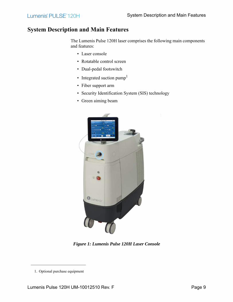
The Lumenis Pulse 120H laser comprises the following main components and features:
• Laser console• Rotatable control screen• Dual-pedal footswitch
• Integrated suction pump1
• Fiber support arm• Security Identification System (SIS) technology• Green aiming beam
Figure 1: Lumenis Pulse 120H Laser Console
1. Optional purchase equipment
Laser Console
Lumenis Pulse 120H UM-10012510 Rev. F Page 10
Laser Console
The laser console houses the control screen, integrated suction pump (optional), the laser control keyswitch, emergency stop knob, main On/Off switch, control electronics, laser source and associated optics, and power supply. Fiber optic delivery systems attach to the fiber receptacle on the front of the console, enabling laser energy to be delivered to the treatment site.
Control Screen
The control screen is an LCD monitor that allows you to select treatment settings outside of the sterile field.
Integrated Suction Pump1
An integrated suction pump and suction control that determines the suction flow rate. The suction pump can be used in conjunction with the laser.
Footswitch
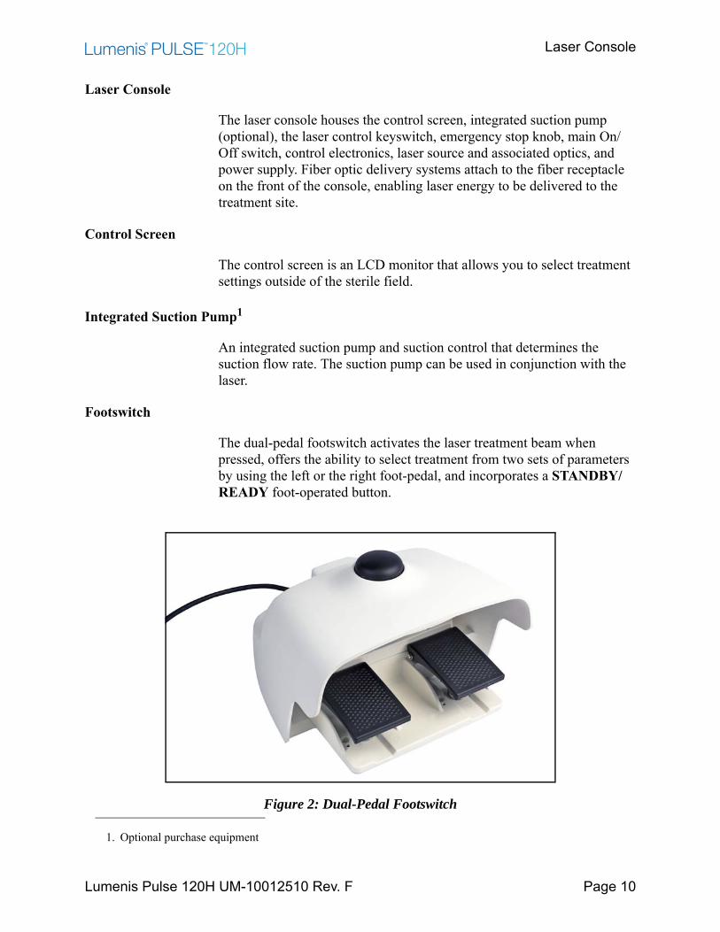
The dual-pedal footswitch activates the laser treatment beam when pressed, offers the ability to select treatment from two sets of parameters by using the left or the right foot-pedal, and incorporates a STANDBY/READY foot-operated button.
Figure 2: Dual-Pedal Footswitch
1. Optional purchase equipment
Fiber Support Arm
Lumenis Pulse 120H UM-10012510 Rev. F Page 11
Fiber Support Arm
The fiber support arm can be used for routing the fiber and suction tube in an ordered and controlled manner.
Delivery Systems
A variety of fiber optic delivery systems are available for use with Lumenis Pulse 120H laser. Refer to the appropriate delivery system instruction guide for specific operating instructions.
CAUTION:Use only Lumenis-approved accessories. Third party accessories are not authorized for use.
Component Checklist
• Lumenis Pulse 120H laser console.
• Detachable dual-pedal footswitch.
• External door interlock connector.
• Keys
• Operator’s manual.
• Fiber support arm.
Holmium Laser Theory of Operation
Lumenis Pulse 120H UM-10012510 Rev. F Page 12
Holmium Laser Theory of Operation
A laser, an acronym for Light Amplification of Stimulated Emission of Radiation, produces a highly concentrated beam of light of a given wavelength. Laser energy is generated by converting electrical energy to light energy using a flash lamp. The flash lamp energy is then used to excite the lasing medium, in this case a holmium YAG laser rod. The laser energy is amplified in the laser resonator cavity and a small portion of the energy is allowed to leak out as the laser working beam.
The Lumenis Pulse 120H holmium laser emits a laser beam at a wavelength of 2100 nm. This wavelength is strongly absorbed by water. Since soft tissue is comprised primarily of water, holmium laser energy can be used effectively for excision, incision, ablation, and vaporization. Holmium laser energy is also very effective in lithotripsy of calculi.
When working in liquid environment the holmium laser energy provides additional safety, since laser energy will be absorbed by the surrounding liquid, limiting its reach to non-target tissue.
The holmium laser wavelength falls in the mid-infrared region of the electromagnetic spectrum. This wavelength is invisible to the human eye. Therefore, a low-power, visible aiming beam is used to verify the laser’s target tissue.
Laser Power Parameters
Tissue laser interaction is primarily governed by the laser wavelength and the target tissue absorption coefficient at that wavelength, defining the effectiveness of the laser energy absorption in the target tissue. However additional characteristics of the specific laser affect the laser tissue interaction.
Pulsed lasers (such as the holmium laser) deliver an average power (measured in Watts) that is achieved by multiplying the laser energy emitted during each pulse (measured in Joules) and the frequency at which these pulses are delivered (measured in Hertz). For example the Lumenis Pulse 120H can deliver a maximum average power of 120W obtained by delivery of 2 Joules per pulse at a frequency of 60 Hz.
Moses Capability
Lumenis Pulse 120H UM-10012510 Rev. F Page 13
Holmium laser systems can deliver the same average power at different settings to achieve different laser tissue effect. Changing the energy of each pulse can be described as the “bite size” of the laser effect, whereas the frequency as the “bite rate”. For example, setting the system at 30W can be performed using the following sets of parameters: 1.5J at 20 Hz or 0.5J at 60 Hz.
When working with calculi, for example, these different settings may affect the stone by breaking the stone into particles versus disintegrating the stone into fine dust. The selection of the appropriate energy and frequency settings is dependent on the procedure and specific target tissue.
Each pulse is delivered at a specific time frame, leading to a rapid rise in temperature of the target tissue. By increasing the pulse duration, the time frame of energy delivery to the tissue changes and thereby changing the temperature profile of the tissue. A different temperature profile may lead to a heating rather than a vaporizing effect and is useful for example when blood vessel coagulation is desired.
The selection of appropriate power parameters and delivery system is dependent on the procedure and the specific patient condition. It is recommended that you become familiar with laser characteristics and techniques by attending courses and consulting with colleagues in order to utilize the lasers capabilities in a safe manner.
Moses Capability
In a liquid environment when laser is emitted from the holmium fiber tip, the water surrounding the tip heats to above the boiling temperature and a vapor bubble is created. The vapor bubble expands from the fiber tip towards the target tissue or stone. As only a portion of the pulse is sufficient to create the vapor bubble, the remaining pulse energy travels through the void contained in the bubble, and is less attenuated compared to travel through liquid water.
When the distance between the fiber tip and the target is very small, this phenomenon is not observed, as most of the energy reaches the target tissue. In contact, the laser is therefore the most efficient. However, when distance is increased, the relative energy that reaches the target is greatly decreased, leading to reduced ablation efficiency of the laser energy. The laser efficiency is therefore much dependent on the distance between the fiber tip and the target. This is defined as the regular mode currently available for all system applications.
Moses Capability
Lumenis Pulse 120H UM-10012510 Rev. F Page 14
The Moses capability introduces a modulation to the energy pulse that - combined with a Moses fiber - enables emission of a controlled portion of energy to create the vapor bubble, while leaving a larger portion as the effective energy portion that travels through the vapor bubble to reach the target tissue. Laser efficiency is therefore less dependent on the distance between the fiber tip and the target and laser energy is delivered with higher efficiency.
NOTE:Moses capability requires the use of dedicated Lumenis Moses fibers and it is available only for systems that incorporate Moses capability which has been activated. A complete discussion of Moses capability and fibers may be found in the Advanced Operations chapter in the section named Moses Capability.
The Ho:YAG wavelength provides effective hemostasis without damaging the surrounding or non-target tissues. Decreasing the laser power density on vascularized tissue is an important tool in bleeding control. Defocusing (increasing the fiber distance from the tissue) is a common method for decreasing power density on tissue. When using the Moses capability, due to its reduced dependence on fiber tip distance from the target, this technique may be less effective.
Safety
Lumenis Pulse 120H UM-10012510 Rev. F Page 15
SafetyIntroduction
This chapter contains important safety information related to the use of the laser system. All operating personnel should familiarize themselves with the contents of this chapter before operating the laser system.
Users must take precautions to prevent exposure of laser energy to the eyes and skin from either direct or diffusely reflected laser beams, except as a therapeutic application. Additional precautions must be taken to prevent fire, electrical injury, and explosion.
CAUTION:Read this operator’s manual carefully. Use of controls or adjustments or performance of procedures other than those specified herein may result in hazardous laser radiation exposure.
Optical Hazards
Laser Safety Eyewear
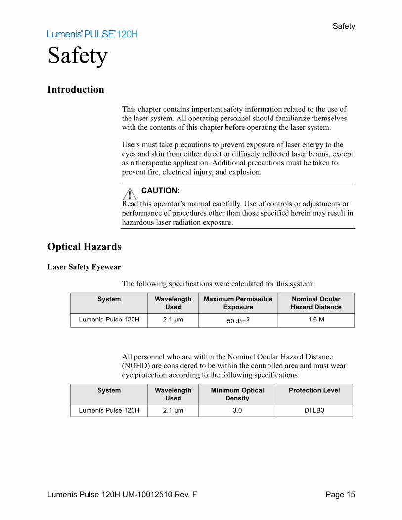
The following specifications were calculated for this system:
All personnel who are within the Nominal Ocular Hazard Distance (NOHD) are considered to be within the controlled area and must wear eye protection according to the following specifications:
System Wavelength Used
Maximum Permissible Exposure
Nominal Ocular Hazard Distance
Lumenis Pulse 120H 2.1 μm 50 J/m2 1.6 M
System Wavelength Used
Minimum Optical Density
Protection Level
Lumenis Pulse 120H 2.1 μm 3.0 DI LB3
Laser Safety Eyewear
Lumenis Pulse 120H UM-10012510 Rev. F Page 16
WARNING:• Select the appropriate laser safety eyewear, for the specific laser in
use, by verifying that the above specifications are indicated on the laser safety eyewear that is at your disposal.
• Always provide eye protection for the patient. Wet thick cloths or wet gauze 4 x 4s can be use together with the patient protective eyewear to reduce patient inconvenience. Never use them to replace protective goggles.
• For periorbital treatment, always protect the patient with dulled, metal eye shields, as severe and irreversible eye damage and scarring may occur from direct or indirect exposure to the treatment beam.
Laser safety eyewear must meet all additional requirements as per ANSI Z136.1 and EN 207.
In addition to providing the required laser safety eyewear, take the following steps to secure the treatment room, or the controlled area:
1. To alert personnel before they enter the controlled area, place a warning sign on the outside of the treatment room door when the laser is in use.
2. Close the treatment room door during operation of the laser.
3. Install an external door remote interlock that automatically disables the laser when the treatment room door is opened.
Additional Ocular Protection
Lumenis Pulse 120H UM-10012510 Rev. F Page 17
Additional Ocular Protection
WARNING:• Always verify that the delivery device is properly connected to the
laser. An improper connection may result in an inadvertent secondary laser beam. Severe eye or tissue damage could occur.
• Never substitute prescription eyewear for the appropriate laser safety eyewear, as severe eye damage could occur. Prescription eyewear can concentrate the laser light to the eye and/or can be shattered by a high power density beam, possibly causing severe eye damage.
• Use caution when performing procedures around the eyes. Severe and irreversible eye damage and scarring may occur from direct or indirect exposure to the treatment beam. The predominant ocular structures at risk are dependent on the laser wavelength in use. In general, visible and near-infrared wavelengths are most damaging to the retina, while ultraviolet or infrared wavelengths are most damaging to the cornea and sclera. Severity of injury depends on how concentrated or diffused the treatment beam is and the length of exposure. A thorough understanding of the specific ocular risks and safety precautions for each laser wavelength is necessary to ensure the safety of the patient and operating personnel.
• Never look directly into any optical fiber, handpiece, probe or laser system aperture while the laser is energized. Severe eye damage could occur. Turn off the laser before inspecting any delivery system or laser components.
Electrical Hazards
WARNING:• Never open the laser console protective covers. Opening the covers
will expose the user to high voltage components, the laser resonator, and possible laser radiation. Only Lumenis-certified service technicians are qualified to work inside the console.
• Do not operate the laser if any of the cords are faulty or frayed. The laser should undergo routine inspection and maintenance per Lumenis manufacturer’s recommendations and institutional standards.
• To avoid risk of electric shock, this equipment must only be connected to a supply mains with protective earth.
Fire Hazards
Lumenis Pulse 120H UM-10012510 Rev. F Page 18
Fire Hazards
WARNING:• Do not use this device in the presence of flammables or explosives,
such as volatile anesthetics, alcohol, certain surgical preparation solutions, and similar substances. An explosion and/or fire could occur.
• The treatment beam can ignite most non-metallic materials. Use fire retardant drapes and gowns. The area around the treatment site can be protected with towels or gauze sponges moistened with sterile saline solution or sterile water. If allowed to dry, protective towels and sponges can increase the potential fire hazard. A UL-approved fire extinguisher and water should be readily available.
• When performing procedures in the perianal area, the flammability of methane gas must be considered. Moistened sponges should be inserted into the rectum.
Additional Safety Considerations
CAUTION:• Smoke evacuation may be required if using the laser in open-air
procedures.• Do not connect any USB flash drives or network cable to the system
during operation.

Protecting Non-Target Tissues
Lumenis Pulse 120H UM-10012510 Rev. F Page 19
Protecting Non-Target Tissues
WARNING:• When using a fiber-optic delivery device, always inspect the fiber-
optic cable to ensure that it has not been kinked, punctured, fractured, or otherwise damaged. The fiber-optic cable may be damaged if stepped on, pulled, left lying in a vulnerable position, kinked, or tightly coiled. Do not clamp the cable with a hemostat or other instruments. If sterile tape is used, always remove the tape before lifting the cable. A damaged fiber-optic cable may cause accidental laser exposure or injury to the treatment room personnel or patient, and/or fire in the treatment room.
• Never deliver the treatment beam to the target tissue if the aiming beam integrity has not been verified; the optical fiber may be damaged. A damaged fiber may cause accidental laser exposure to the treatment room personnel or patient, and/or fire in the treatment room.
• Except during actual treatment, the laser must always be in standby mode. Maintaining the laser in standby mode prevents accidental laser exposure if the footswitch is inadvertently pressed.
CAUTION:• To prevent accidental laser discharge, always make sure that the
footswitch is not being operated while connecting the delivery system.• Never place hands or other objects in the path of the laser beam.
Severe burns could occur.• Only the person directing the aim of the laser beam should have access
to the laser footswitch. Use caution pressing the laser footswitch when it is in proximity to footswitches for other equipment. Verify the footswitch pressed is the correct one in order to avoid accidental laser exposure.
• Never discharge the laser without a target to absorb it and without consideration given to what lies behind the target. Place energy-absorbing material behind the target tissue when aiming the laser at an oblique target.
Safety Indicators
Lumenis Pulse 120H UM-10012510 Rev. F Page 20
Safety Indicators
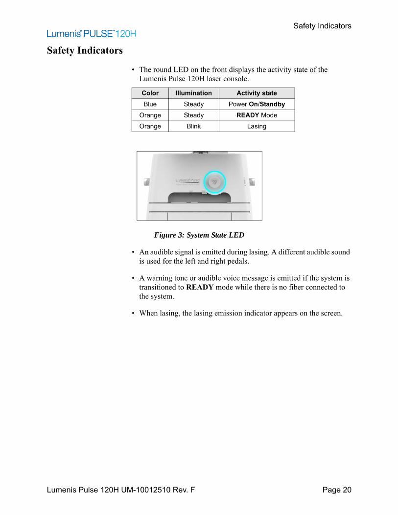
• The round LED on the front displays the activity state of the Lumenis Pulse 120H laser console.
Figure 3: System State LED
• An audible signal is emitted during lasing. A different audible sound is used for the left and right pedals.
• A warning tone or audible voice message is emitted if the system is transitioned to READY mode while there is no fiber connected to the system.
• When lasing, the lasing emission indicator appears on the screen.
Color Illumination Activity stateBlue Steady Power On/Standby
Orange Steady READY ModeOrange Blink Lasing
Warning, Certification and Identification Labels
Lumenis Pulse 120H UM-10012510 Rev. F Page 21
Warning, Certification and Identification Labels
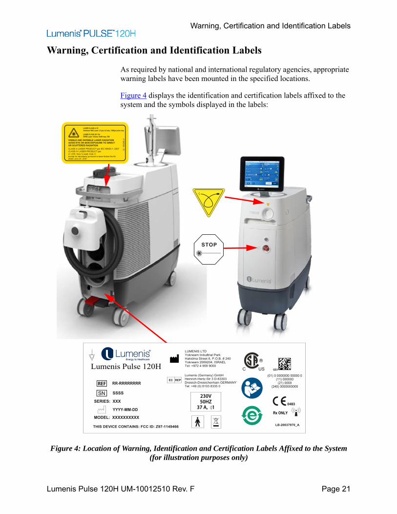
As required by national and international regulatory agencies, appropriate warning labels have been mounted in the specified locations.
Figure 4 displays the identification and certification labels affixed to the system and the symbols displayed in the labels:
Figure 4: Location of Warning, Identification and Certification Labels Affixed to the System (for illustration purposes only)
STOP
LASER CLASS 4 / IVHolmium:YAG Laser: 2.1μm, 6J max, 1300μs pulse max
LASER CLASS 3R / IllaDPSS Laser: 532nm, 5mW max, CW
VISIBLE AND INVISIBLE LASER RADIATIONAVOID EYE OR SKIN EXPOSURE TO DIRECTOR SCATTERED RADIATIONCLASS 4 LASER PRODUCT per IEC 60825-1: 2007CLASS IV LASER PRODUCT per 21 CFR 1040.10 AND 1040.11
LB -
1003
2650
_B
except for deviations pursuant to laser Notice No.50dated June 24, 2007
LUMENIS LTDYokneam Industrial ParkHakidma Street 6, P.O.B. # 240Yokneam 2069204, ISRAELTel: +972 4 959 9000
Lumenis (Germany) GmbHHeinrich-Hertz-Str 3 D-63303Dreieich-Dreieichenhain GERMANYTel: +49 (0) 6103 8335 0
EC REP
Lumenis Pulse 120H
SN
RR-RRRRRRRR
(01) 0 0000000 00000 0(11) 000000
(21) 0000(240) 0000000000
LB-20037970_A
0483
Rx ONLY
SERIES: XXX
SSSS
MODEL: XXXXXXXXXX
YYYY-MM-DD
GS1
THIS DEVICE CONTAINS: FCC ID: Z97-1149466
230V50HZ
37 A, 1
Explanation of the symbols used in the labels
Lumenis Pulse 120H UM-10012510 Rev. F Page 22
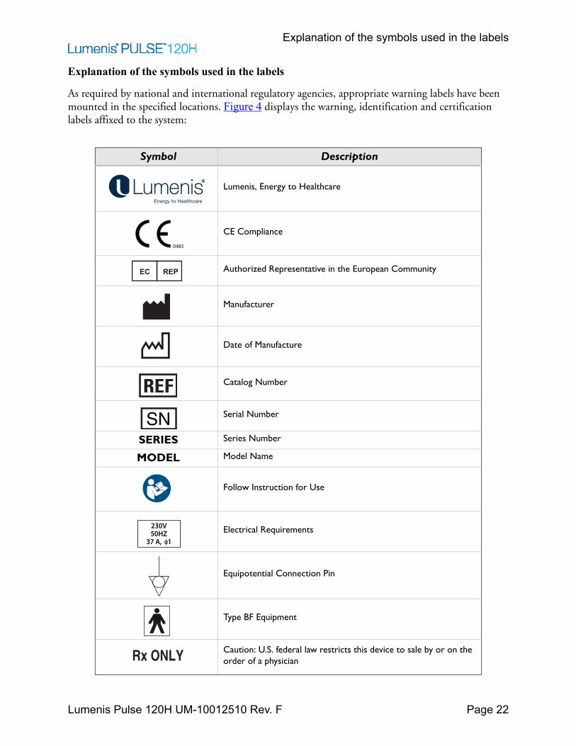
Explanation of the symbols used in the labels
As required by national and international regulatory agencies, appropriate warning labels have been mounted in the specified locations. Figure 4 displays the warning, identification and certification labels affixed to the system:
Symbol Description
Lumenis, Energy to Healthcare
CE Compliance
Authorized Representative in the European Community
Manufacturer
Date of Manufacture
Catalog Number
Serial Number
SERIES Series Number
MODEL Model Name
Follow Instruction for Use
Electrical Requirements
Equipotential Connection Pin
Type BF Equipment
Caution: U.S. federal law restricts this device to sale by or on the order of a physician
0483
EC REP
SN
230V50HZ
37 A, 1
Rx ONLY
Explanation of the symbols used in the labels
Lumenis Pulse 120H UM-10012510 Rev. F Page 23
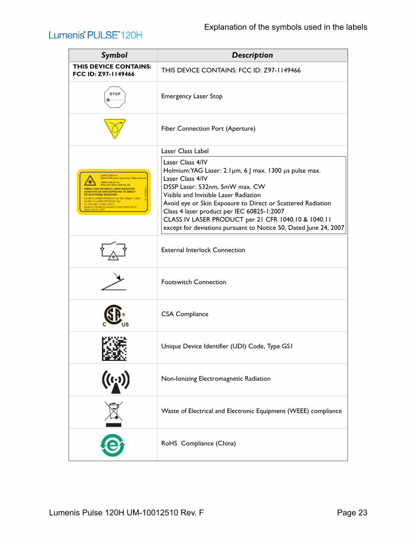
THIS DEVICE CONTAINS: FCC ID: Z97-1149466
THIS DEVICE CONTAINS: FCC ID: Z97-1149466
Emergency Laser Stop
Fiber Connection Port (Aperture)
Laser Class Label
External Interlock Connection
Footswitch Connection
CSA Compliance
Unique Device Identifier (UDI) Code, Type GS1
Non-Ionizing Electromagnetic Radiation
Waste of Electrical and Electronic Equipment (WEEE) compliance
RoHS Compliance (China)
Symbol Description
STOP
LASER CLASS 4 / IVHolmium:YAG Laser: 2.1μm, 6J max, 1300μs pulse max
LASER CLASS 3R / IllaDPSS Laser: 532nm, 5mW max, CW
VISIBLE AND INVISIBLE LASER RADIATIONAVOID EYE OR SKIN EXPOSURE TO DIRECTOR SCATTERED RADIATIONCLASS 4 LASER PRODUCT per IEC 60825-1: 2007CLASS IV LASER PRODUCT per 21 CFR 1040.10 AND 1040.11
LB -
1003
2650
_B
except for deviations pursuant to laser Notice No.50dated June 24, 2007
Laser Class 4/IVHolmium:YAG Laser: 2.1µm, 6 J max. 1300 µs pulse max.Laser Class 4/IVDSSP Laser: 532nm, 5mW max. CWVisible and Invisible Laser RadiationAvoid eye or Skin Exposure to Direct or Scattered RadiationClass 4 laser product per IEC 60825-1:2007 CLASS IV LASER PRODUCT per 21 CFR 1040.10 & 1040.11 except for deviations pursuant to Notice 50, Dated June 24, 2007
Explanation of the symbols used in the labels
Lumenis Pulse 120H UM-10012510 Rev. F Page 24
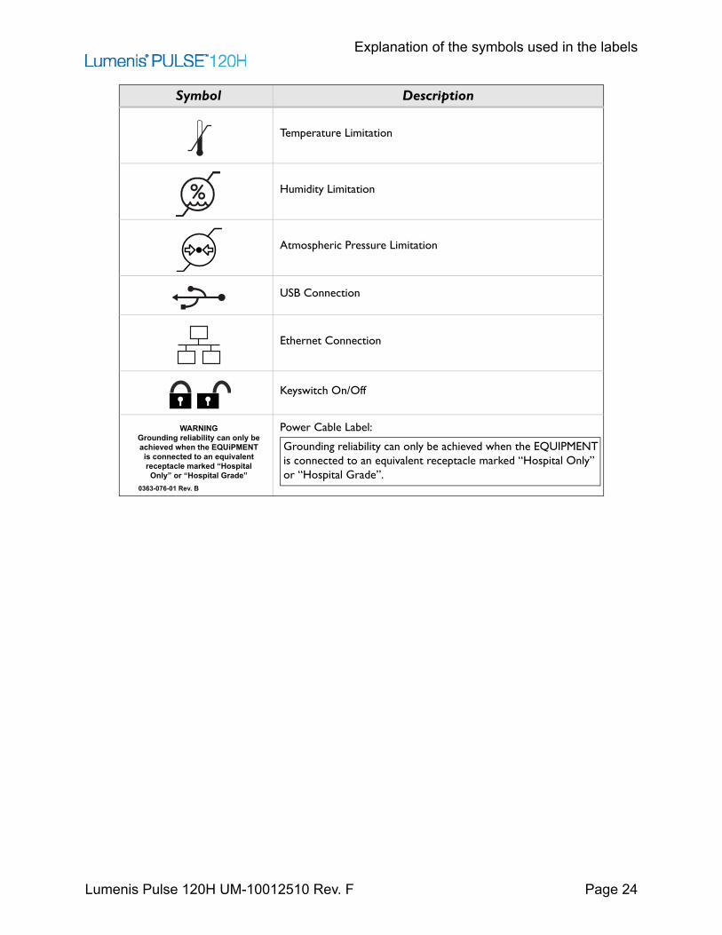
Temperature Limitation
Humidity Limitation
Atmospheric Pressure Limitation
USB Connection
Ethernet Connection
Keyswitch On/Off
Power Cable Label:
Symbol Description
WARNINGGrounding reliability can only beachieved when the EQUiPMENTis connected to an equivalentreceptacle marked “Hospital
Only” or “Hospital Grade”0363-076-01 Rev. B
Grounding reliability can only be achieved when the EQUIPMENT is connected to an equivalent receptacle marked “Hospital Only” or “Hospital Grade”.
Clinical Guide
Lumenis Pulse 120H UM-10012510 Rev. F Page 25
Clinical GuideLumenis recommends that physicians learn and gather additional knowledge related to the Lumenis Pulse 120H. For details on courses and training sessions available at Lumenis, contact your Lumenis representative.Lumenis does not make recommendations regarding the practice of medicine. Laser presets are provided by the software operating system for your convenience. Individual treatment should be based on clinical training, clinical observation of laser-tissue interaction, and appropriate clinical endpoints.
WARNING:Unauthorized use of this system may expose the operator/patient to potential electrical energy and laser radiation hazards.
NOTE:The Lumenis Pulse 120H system is furnished with predefined parameter sets of treatment parameters, called Lumenis Presets. These presets are based on successful results obtained by experienced physicians using Holmium laser systems.
The Ho:YAG wavelength has been shown to be a safe and effective tool for the ablation, vaporization, incision, excision, and coagulation of a variety of soft tissues. This has been demonstrated by both clinical and preclinical studies. The 2100 nm wavelength of the holmium laser is highly absorbed by water (absorption peak of water: 1940 nm). The absorption of the laser energy by water produces an energy density that heats the tissue to greater than 100°C thus vaporizing or ablating the tissue without deep coagulation, allowing for precise incision (cutting) and excision (dissection) when in direct contact with the tissue. When the laser is not in direct contact with the tissue, the produced heat can dissipate, leading to coagulation of vessels to a depth of up to 3 mm.
Effect on Soft Tissue
The depth of the incision is determined by the amount of energy (in Joules) applied. The rate at which the incision is made is dependent upon the rate of energy pulses being delivered to the target tissue (in pulses per second, or Hertz). Optimum incision of tissue is accomplished by balancing the depth of the incision and the rate at which the incision is being formed. The physician may control both the energy setting and the
Effects on Stones
Lumenis Pulse 120H UM-10012510 Rev. F Page 26
repetition rate of the laser, depending upon the specific type of soft tissue, the desired tissue effect (excision, ablation, or coagulation), and the speed at which this effect should be achieved.The Ho:YAG wavelength provides effective hemostasis without damaging the surrounding or non-target tissues. Decreasing the laser power density on vascularized tissue is an important tool in bleeding control. This may be achieved in 3 ways:
• Increasing the pulse width/duration.• Reducing the energy per pulse and repetition rate.• Defocusing the beam without changing the system controls by
moving the tip of the fiber away from the target tissue approximately 2 to 5 millimeters.
Effects on Stones
The holmium wavelength's high absorption in water and ability to produce water vapor is also utilized for fragmenting stones. Urinary and biliary stones contain a sufficient amount of water needed to absorb the laser energy, heat and produce a vapor that causes enough pressure in the specific location that will lead to the fracturing of the stone. The power required to perform this application can be controlled by the pulse energy that is delivered to the tissue and the frequency at which the pulses are emitted. Both of these factors affect stone fragmentation. The holmium wavelength's high absorption in water is advantageous when working in a water filled environment, as it enables safe delivery of energy without harming non-targeted tissue. Any water that interfaces between the laser and the tissue absorbs the laser energy, therefore distance between the laser and non-target tissue ensures its safety. Only laser energy that is delivered directly to the target tissue, in contact, will result in a significant tissue effect.
NOTE:When treating calculi (e.g. urinary, biliary) migration of the stone may occur due to the mechanical effect of the laser energy (retropulsion). Migration may be avoided by several lasing techniques that are based on the laser interaction with the stone. Firstly, decreasing the laser energy and increasing the pulse frequency to maintain the required power output. Secondly (in Moses mode), maintaining the energy and frequency and increasing the pulse width.
Laser energy can be delivered to the tissue using various delivery devices. These include straight-firing and side-firing fibers. Refer to the specific delivery devices for detailed information.
Indications for Use
Lumenis Pulse 120H UM-10012510 Rev. F Page 27
NOTE:Physicians are encouraged to continuously consult current literature and information provided in advanced workshops to keep abreast of the most effective and up-to-date practices.
Indications for Use
The Lumenis Pulse 120H System with Delivery Devices and Accessories are intended for use in surgical procedures involving open, laparoscopic and endoscopic ablation, vaporization, excision, incision, and coagulation of soft tissue in medical specialties including: urology; urinary lithotripsy; arthroscopy; discectomy; E.N.T. surgery; gynecological surgery; pulmonary surgery; gastroenterology surgery; dermatology and plastic surgery and general surgery.
In China, Korea and Taiwan the Lumenis Pulse 120H system with Delivery Devices and Accessories are intended for use in surgical procedures that require incision, excision and ablation (vaporization and removal) of soft tissue and for Lithotripsy.
Contraindications
The use of a laser instrument for an application is at the physician’s discretion except in cases where the indication has been contraindicated.• Inability to receive endoscopic or laparoscopic treatment.• Intolerance to anesthesia.• Resection or excision of large, highly vascularized organs.
Specific Contraindications in Urology
• Carcinoma of the prostate.
Specific Contraindications in Gynecology
• Septic peritonitis.• Intestinal obstruction.• Septic shock.• Resection or excision of large, highly vascularized organs.
Warnings and Precautions
Lumenis Pulse 120H UM-10012510 Rev. F Page 28
NOTE:Lumenis has no clinical information concerning the safety of laser treatment on pregnant or nursing women.
Warnings and Precautions
This section contains warnings and precautions that are applicable to surgical procedures specifically related to the use of this system.• Holmium lasers are intended solely for use by physicians trained in the
use of the Ho:YAG (2.1 µm) wavelength.• Incorrect treatment settings can cause serious tissue damage. Therefore,
it is recommended that you use the lowest acceptable treatment settings until familiar with the instrument’s capabilities. Use extreme caution until the biological interaction between the laser energy and tissue is thoroughly understood.
• Due to interaction between flammable gases in the operating field and the laser energy a flash fire may occur. Therefore, during laser procedures, measures to minimize this potential hazard should be practiced (e.g. avoid administration of inhaled general anesthetics; reduce oxygen levels during mechanical ventilation, use of laser- resistant endotracheal tubes). The flammability of methane gas must also be considered when treating in or near the perianal area.
• The laser should be used only on tissues that are fully observable. Do not use the laser if the desired target is not visible. All available measures to visualize the target tissue (e.g. copious irrigation, hemostasis) should be taken.
• When using endoscopic equipment confirm that the tip of the fiber optic delivery device extends at least 6 mm beyond the end of the scope during laser treatment. Activating the laser when the tip of the delivery device is within the scope can result in penetration of holmium laser energy through the scope and destruction of the scope.
• Use of the laser on anatomical structures in proximity to known critical structures, such as large arteries, veins, bowel, ureter, bladder, nerves, etc., should be performed carefully to avoid inadvertent or unintended damage of such structures. If applicable, maintain irrigation in the treatment area to reduce heat accumulation.
Complications
Lumenis Pulse 120H UM-10012510 Rev. F Page 29
• Use caution when treating patients who have recently undergone radiotherapy. Such patients may be at greater risk of tissue perforation or erosion.
• Highly vascularized anatomical structures should be approached with caution, taking into account the limited coagulative properties of the laser. Electrocautery and/or suture (ligature) should be easily accessible in the event that a bleeding vessel is larger than possible to control with the laser. The risk of bleeding may be higher in patients taking anticoagulants/ platelet aggregates.
• Baskets, guide wires, and other surgical accessories may be damaged by direct contact with the laser treatment beam.
Complications
The following is a list of general complications that are related to surgery and within this context, laser surgery. The potential complications encountered in endoscopic laser surgery are the same as those normally encountered in conventional endoscopic surgery. Refer to updated literature for specific procedure related complications. • As with conventional surgery, the possibility of complications and
adverse events, such as chills, fever, edema, hemorrhage, inflammation, tissue necrosis, or infection may occur following treatment. In extreme cases, death may occur due to procedural complications, concurrent illness, or laser application.
• As with any surgical procedure there is a possibility of infection or scarring. Therefore, appropriate pre and post-surgical care should always be practiced.
• As with any conventional surgery discontinue laser treatment immediately if the patient develops any cardiopulmonary problems.
• As with any conventional surgery, acute pain may occur immediately following laser therapy and may persist for as long as 48 hours.
• Immediately following laser therapy, the patient may experience fever and leukocytosis, which are commonly associated with tissue destruction. These generally resolve without treatment. Remnants of destructed tissue may become necrotic or infected. If a question of infection exists, appropriate treatment should be carried out.
Detailed Indications for Use
Lumenis Pulse 120H UM-10012510 Rev. F Page 30
• Patients may experience bleeding at the site of laser therapy. Post treatment hematocrits are recommended to identify this potential complication.
• Sepsis can result from performing any surgical procedure. If a question of sepsis exists, appropriate evaluations should be made.
• Perforation may occur as a result of laser treatment. To diagnose perforations, patients must be carefully followed post-operatively with appropriate tests.
• As with any conventional laparoscopic surgery, the use of gas to insufflate the abdomen may lead to a gas embolus. In the extreme case, death may result from an embolus. The use of carbon dioxide gas for insufflation will minimize patient risk, as it is highly soluble in blood. Insufflation pressure should be set to minimum settings for effective insufflation.
Detailed Indications for Use
The Lumenis Pulse 120H system with delivery devices and accessories are intended for use in surgical procedures involving open, laparoscopic and endoscopic ablation, vaporization, excision, incision, and coagulation of soft tissue in medical specialties including: urology; urinary lithotripsy; arthroscopy; discectomy; E.N.T. surgery; gynecological surgery; pulmonary surgery; gastroenterology surgery; dermatology and plastic surgery and general surgery.The Lumenis Pulse 120H system with delivery devices and accessories are indicated for use in the performance of specific surgical applications as follows.
Urology
Lumenis Pulse 120H UM-10012510 Rev. F Page 31
Urology
• Endoscopic transurethral incision of the prostate (TUIP), bladder neck incision of the prostate (BNI), holmium laser ablation of the prostate (HoLAP), holmium laser enucleation of the prostate (HoLEP), holmium laser resection of the prostate (HoLRP), hemostasis, vaporization and excision for treatment of benign prostatic hypertrophy (BPH).
• Open and endoscopic urological surgery (ablation, vaporization, incision, excision and coagulation of soft tissue) including treatment of:BladderSuperficial and invasive bladder, urethral and ureteral tumors.CondylomasLesions of external genitaliaUreteral and penile hemangiomaUreteral stricturesBladder neck obstructions
• Urinary Lithotripsy including:Endoscopic fragmentation of urinary (urethral, ureteral, bladder
and renal) calculi, including cystine, calcium oxalate, monohydrate and calcium oxalate dihydrate stones.Treatment of distal impacted fragments of steinstrasse when guide
wires cannot be passed.
Arthroscopy
Lumenis Pulse 120H UM-10012510 Rev. F Page 32
Arthroscopy
• Arthroscopy (ablation, excision and coagulation of soft and cartilaginous tissue) in various small and large joints of the body, excluding the spine, including:MeniscectomyPlica removalLigament and tendon releaseContouring and sculpting of articular surfacesDebridement of inflamed synovial tissue (synovectomy)Loose body debridementChondromalacia and tearsLateral retinecular releaseCapsulectomy in the kneeChondroplasty in the kneeChondrornalacia ablation
• Discectomy including:Percutaneous vaporization of the L4-5 and LS-Sl lumbar discs of
the vertebral spine; open and arthroscopic spine procedures; foraminotomy.

General Surgery
Lumenis Pulse 120H UM-10012510 Rev. F Page 33
General Surgery
• Open, laparoscopic, and endoscopic general surgery (vaporization, ablation, incision, and coagulation of soft tissue) including:CholecystectomyLysis of adhesionsAppendectomyBiopsy, pylorostenotomy, and removal of polyps of the sigmoid
colon.Skin incisionTissue dissectionExcision of external tumors and lesionsComplete or partial resection of internal organs, tumors and
lesions.MastectomyHepatectomyPancreatectomySplenectomyThyroidectomyParathyroidectomyHerniorrhaphyTonsillectomyLymphadenectomyPartial nephrectomyOpilonidal cystectomyResection of lipomaDebridement of decubitus ulcerHemorrhoidsDebridement of statis ulcerBiopsy
ENT Surgery
Lumenis Pulse 120H UM-10012510 Rev. F Page 34
ENT Surgery
• Endoscopic endonasal/sinus surgery (ablation, vaporization, incision, and coagulation of soft tissue and cartilage) including:Partial turbinectomyEthmoidectomyPolypectomyMaxillary antrostomyFrontal smusotomySphenoidotomyDacryocystorhinostomy (DCR)Functional endoscopic sinus surgery (FESS)
• Endonasal surgery (ablation, vaporization, incision, excision, and coagulation of soft tissue) including:Lesions or tumors of the oral, nasal, glossal, pharyngeal and
laryngeal tissuesTonsillectomyAdenoidectomy
• Open and laparoscopic gynecological surgery (ablation, vaporization, incision, excision, and coagulation of soft tissue).
Gynecological Surgery
• Open and laparoscopic gynecological surgery (ablation, vaporization, incision, excision, and coagulation of soft tissue).
Gastroenterology Surgery
Lumenis Pulse 120H UM-10012510 Rev. F Page 35
Gastroenterology Surgery
• Open and endoscopic gastroenterology surgery (ablation, vaporization, incision, excision, resection, coagulation and hemostasis, including:Gall bladder calculiBiliary/bile duct calculiBenign and malignant neoplasmPolypsColitisUlcersAngiodysplasiaHemorrhoidsVaricesEsophagitisEsophageal ulcerMallory-Weiss tearGastric ulcerDuodenal ulcerNon-bleeding ulcerGastric erosionsColorectal cancerGastritisBleeding tumorsPancreatitisVascular malformationsTelangiectasiasTelangiectasias of the Osler-Weber-Renu disease
Pulmonary Surgery
• Open and endoscopic pulmonary surgery (cutting, ablation, vaporization, incision, excision and coagulation of soft tissue.
Dermatology and Plastic Surgery
Lumenis Pulse 120H UM-10012510 Rev. F Page 36
Dermatology and Plastic Surgery
• Incision, excision, resection, ablation, coagulation, hemostasis and vaporization of soft, mucosal, fatty and cartilaginous tissues, in therapeutic plastic, dermatologic and aesthetic surgical procedures, including:
• Scars• Tattoo removal• Vascular lesions• Port wine stains• Hemangioma• Telangiectasia of the face and leg• Rosacea• Corns• Papillomas• Basal cell carcinomas• Lesions of skin and subcutaneous tissue• Plantar warts• Periungual and subungual warts• Debridement of decubitus ulcer• Skin tag vaporization

Preparing the System for Use
Lumenis Pulse 120H UM-10012510 Rev. F Page 37
Preparing the System for UseThe laser is shipped directly from the factory to your site. Your local Lumenis service representative initially uncrates, inspects, sets up, and installs the laser to ensure that it is working properly. In addition, Lumenis provides in-service training to ensure that your surgical staff is experienced with the performance and safety considerations of the laser. Thereafter, you or the nursing staff at your facility will perform the daily maintenance routines associated with the laser and any delivery systems used during surgery, including inspecting and cleaning the laser and delivery systems; connecting, disconnecting, and sterilizing the delivery systems; and verifying the aiming beam integrity. These procedures are detailed in this manual and in the delivery system instruction guide. If your scheduled surgical procedure requires disposable delivery devices or accessories, it is helpful to have extra items ready and available in the treatment room should they be needed to complete a procedure.
WARNING:• Verify that all persons in the treatment room are wearing the
appropriate laser safety eyewear. Refer to Laser Safety Eyewear.• Before connecting the Lumenis Pulse 120H components, inspect the
individual components, cables, and electrical connections for dirt, debris, or damage. Verify that the electrical cables are not frayed or split. Contact your local Lumenis service representative if any component appears damaged.
Moving the System
Lumenis Pulse 120H UM-10012510 Rev. F Page 38
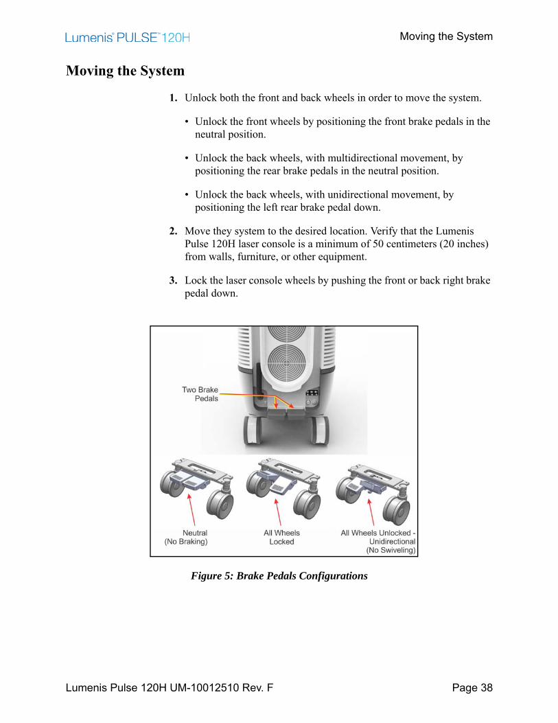
Moving the System
1. Unlock both the front and back wheels in order to move the system.
• Unlock the front wheels by positioning the front brake pedals in the neutral position.
• Unlock the back wheels, with multidirectional movement, by positioning the rear brake pedals in the neutral position.
• Unlock the back wheels, with unidirectional movement, by positioning the left rear brake pedal down.
2. Move they system to the desired location. Verify that the Lumenis Pulse 120H laser console is a minimum of 50 centimeters (20 inches) from walls, furniture, or other equipment.
3. Lock the laser console wheels by pushing the front or back right brake pedal down.
Figure 5: Brake Pedals Configurations
Adjusting the Fiber Support Arm
Lumenis Pulse 120H UM-10012510 Rev. F Page 39
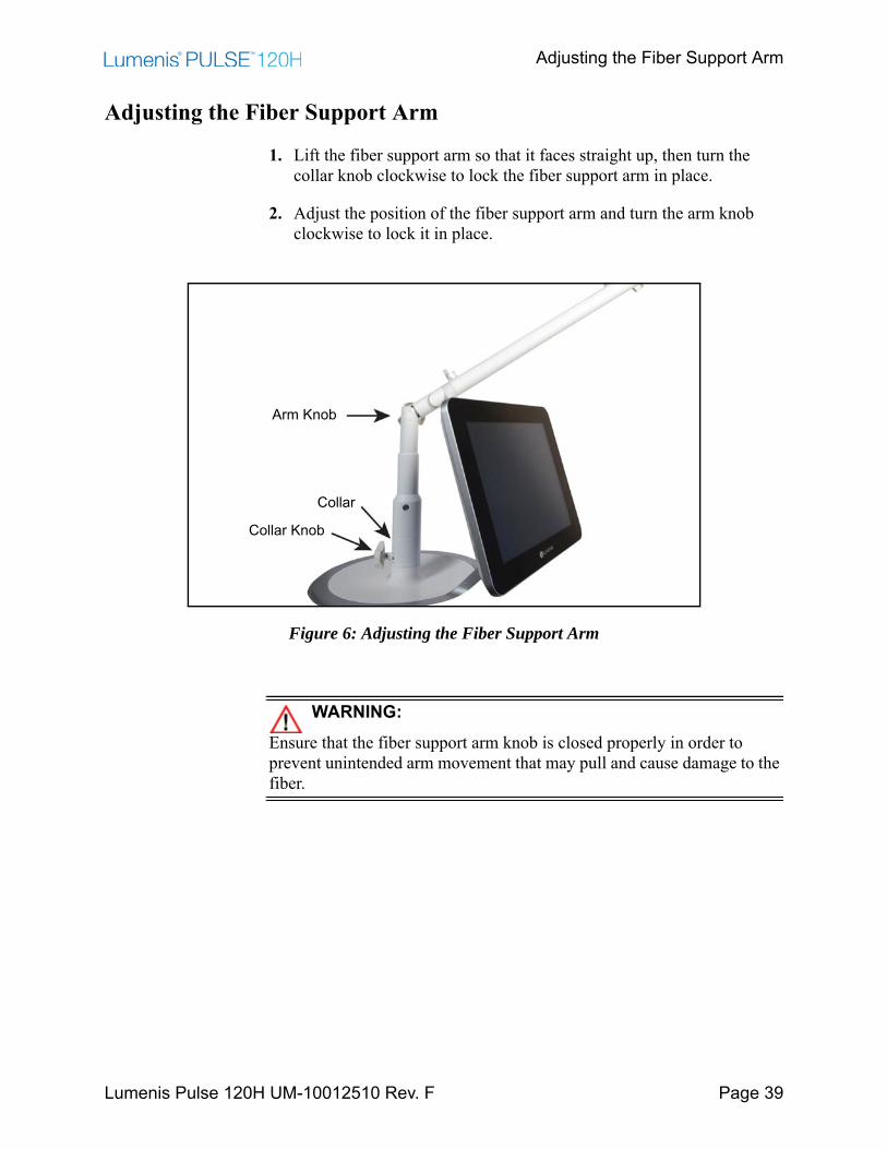
Adjusting the Fiber Support Arm
1. Lift the fiber support arm so that it faces straight up, then turn the collar knob clockwise to lock the fiber support arm in place.
2. Adjust the position of the fiber support arm and turn the arm knob clockwise to lock it in place.
Figure 6: Adjusting the Fiber Support Arm
WARNING:Ensure that the fiber support arm knob is closed properly in order to prevent unintended arm movement that may pull and cause damage to the fiber.
Arm Knob
Collar
Collar Knob
Adjusting the Screen
Lumenis Pulse 120H UM-10012510 Rev. F Page 40
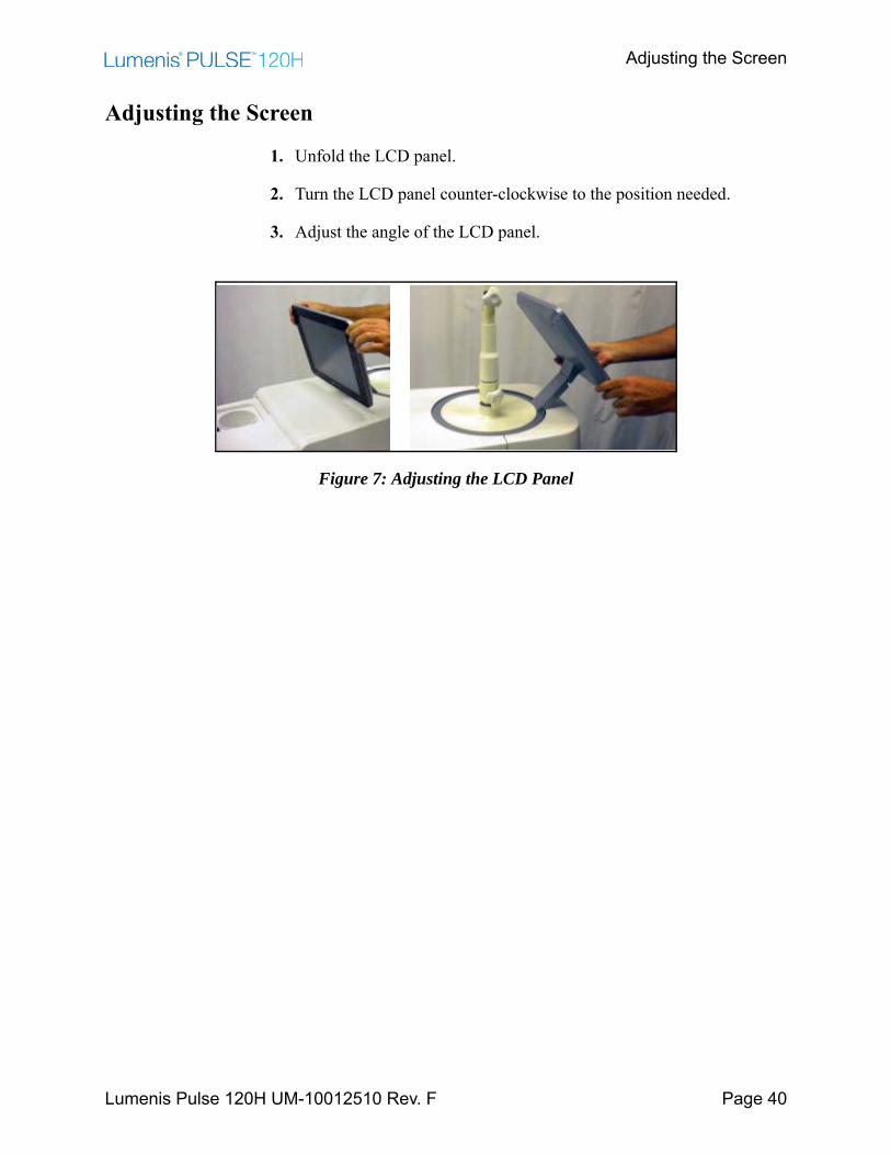
Adjusting the Screen
1. Unfold the LCD panel.
2. Turn the LCD panel counter-clockwise to the position needed.
3. Adjust the angle of the LCD panel.
Figure 7: Adjusting the LCD Panel
Connecting the Footswitch
Lumenis Pulse 120H UM-10012510 Rev. F Page 41
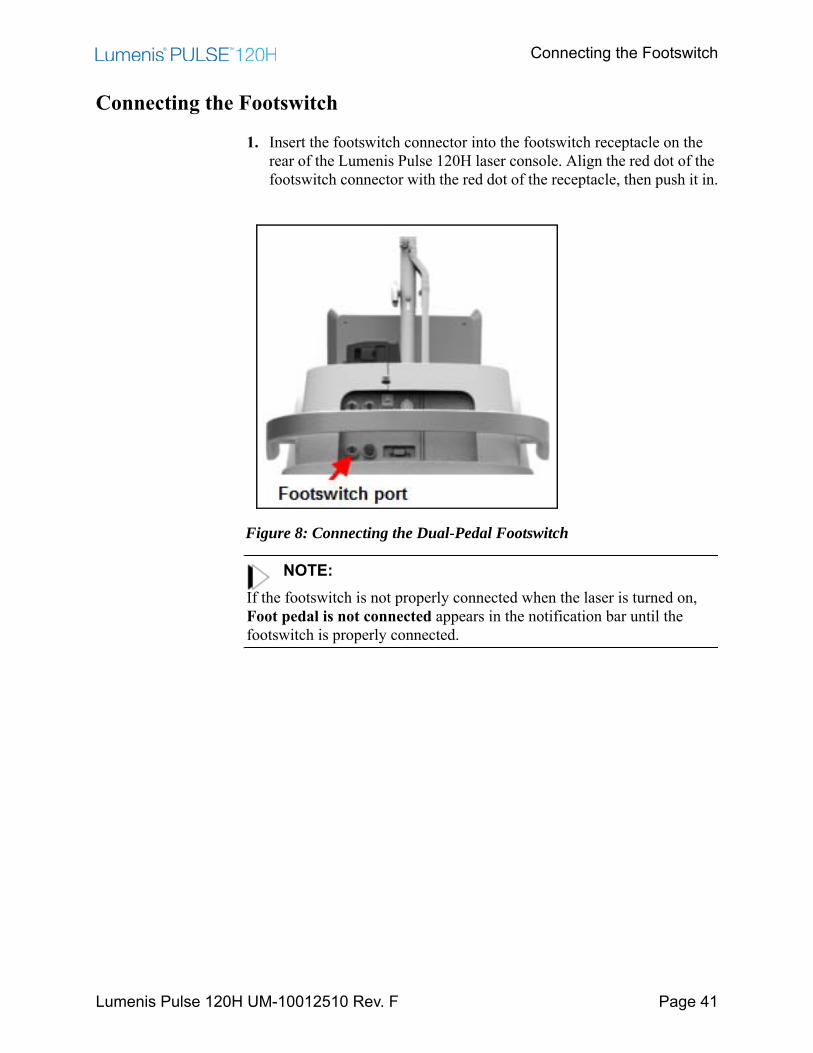
Connecting the Footswitch
1. Insert the footswitch connector into the footswitch receptacle on the rear of the Lumenis Pulse 120H laser console. Align the red dot of the footswitch connector with the red dot of the receptacle, then push it in.
Figure 8: Connecting the Dual-Pedal Footswitch
NOTE:If the footswitch is not properly connected when the laser is turned on, Foot pedal is not connected appears in the notification bar until the footswitch is properly connected.

Inserting the External Door Interlock Connector
Lumenis Pulse 120H UM-10012510 Rev. F Page 42
Inserting the External Door Interlock Connector
The external door interlock is a safety feature that disables the laser if the treatment room doors are opened or the external door interlock connector is removed while the laser is in ready mode.
The laser remains inoperative until the connector is inserted.
1. Align the pins of the external door interlock connector with the socket of the external interlock receptacle.
2. Insert the external interlock connector into the external interlock receptacle.
3. Turn the metal lock clockwise until it screws in.
4. If the treatment door is opened (when the external door interlock is used) or if the external door interlock connector is removed, the laser automatically disables and returns to STANDBY mode and a notification appears in the notification bar.
5. To resume treatment, close the treatment room door or reinsert the external door interlock connector, and press the READY button.
Figure 9: Reinsert the External Door Interlock
Plugging in the Main Power Cable
Lumenis Pulse 120H UM-10012510 Rev. F Page 43
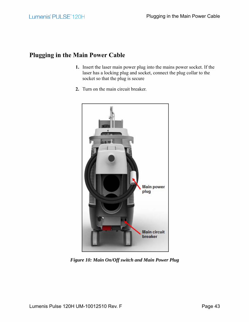
Plugging in the Main Power Cable
1. Insert the laser main power plug into the mains power socket. If the laser has a locking plug and socket, connect the plug collar to the socket so that the plug is secure
2. Turn on the main circuit breaker.
Figure 10: Main On/Off switch and Main Power Plug
Connecting the Delivery System
Lumenis Pulse 120H UM-10012510 Rev. F Page 44
Connecting the Delivery System
Before connecting the delivery system to the laser, refer to the appropriate delivery system instruction guide for specific instructions, such as delivery system inspection, sterilization, and assembly.
WARNING:• Carefully inspect the delivery system sterile packaging to ensure that
it has not been torn or punctured. If there is any damage to the sterile packaging, do not use the delivery system.
• When using a fiber optic delivery device, always inspect the fiber optic cable to ensure that it has not been kinked, punctured, fractured, or otherwise damaged. The fiber optic cable may be damaged if stepped on, pulled, left lying in a vulnerable position, kinked, or tightly coiled. Do not clamp the cable with a hemostat or other instruments. If sterile tape is used, always remove the tape before lifting the cable. A damaged fiber optic cable may cause accidental laser exposure or injury to the treatment room personnel or patient, and/or fire in the treatment room.
• To avoid possible damage to the optical system, use only qualified Lumenis delivery systems. Using other than Lumenis delivery systems may jeopardize safe operation or damage the laser and will void your Lumenis warranty or service contract.
• To prevent accidental laser discharge, always turn off the laser before connecting the delivery system.
NOTE:The SIS enabled Lumenis Pulse 120H system will only operate with Lumenis-qualified SIS (Secure Identification System) optical delivery fibers. Attaching any other type of fiber will generate an error message and laser emission will be disabled.
Connecting the Delivery System
Lumenis Pulse 120H UM-10012510 Rev. F Page 45
To ensure sterility of the delivery system, the following aseptic technique must be used when you connect the delivery system to the laser:
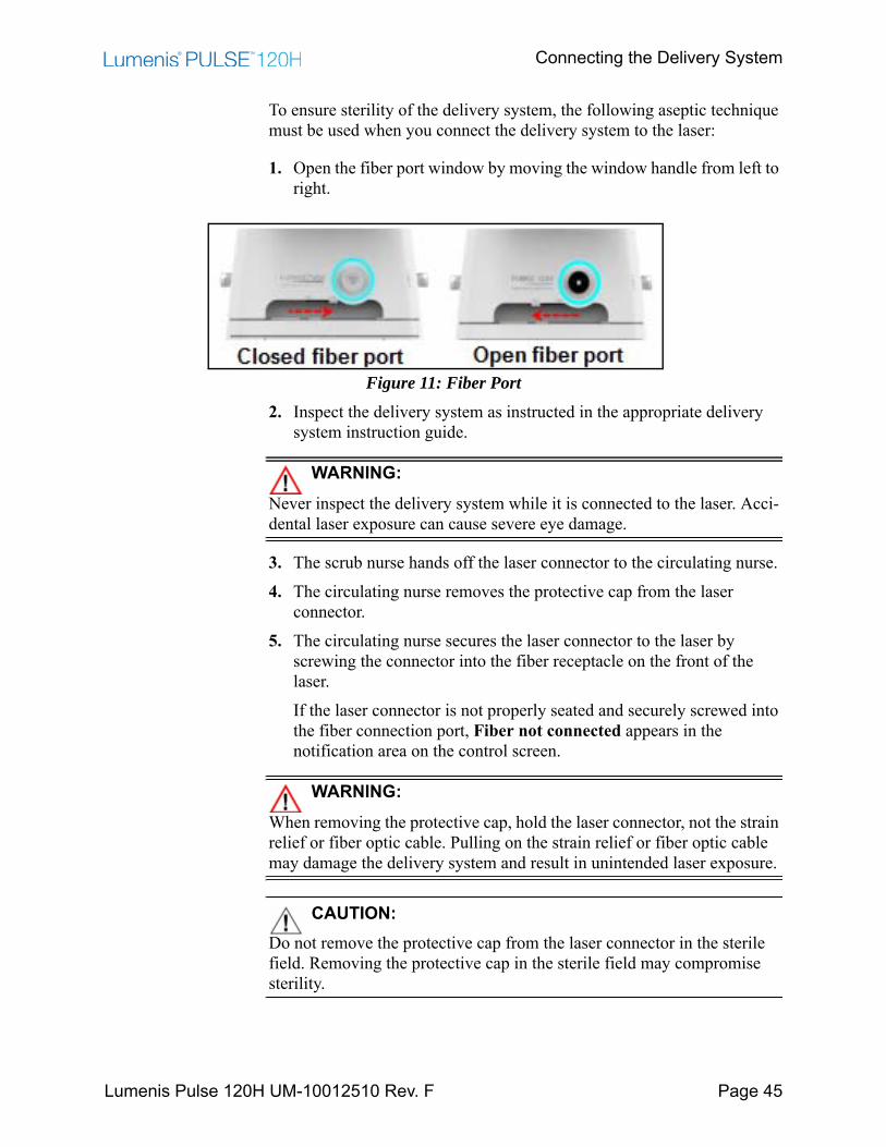
1. Open the fiber port window by moving the window handle from left to right.
Figure 11: Fiber Port2. Inspect the delivery system as instructed in the appropriate delivery
system instruction guide.
WARNING:Never inspect the delivery system while it is connected to the laser. Acci-dental laser exposure can cause severe eye damage.
3. The scrub nurse hands off the laser connector to the circulating nurse.4. The circulating nurse removes the protective cap from the laser
connector.5. The circulating nurse secures the laser connector to the laser by
screwing the connector into the fiber receptacle on the front of the laser.If the laser connector is not properly seated and securely screwed into the fiber connection port, Fiber not connected appears in the notification area on the control screen.
WARNING:When removing the protective cap, hold the laser connector, not the strain relief or fiber optic cable. Pulling on the strain relief or fiber optic cable may damage the delivery system and result in unintended laser exposure.
CAUTION:Do not remove the protective cap from the laser connector in the sterile field. Removing the protective cap in the sterile field may compromise sterility.

Connecting the Suction System
Lumenis Pulse 120H UM-10012510 Rev. F Page 46
Connecting the Suction System1
The surgeon may use Lumenis Pulse 120H laser's built-in suction system to remove tissue, liquids, stones or other debris into the collection container. The Lumenis-supplied disposables required for this are:
• Collection container kit
• Sterile aspiration tube
• Non-sterile drainage tube
CAUTION:Use only Lumenis-approved accessories. Third party accessories are not authorized for use.
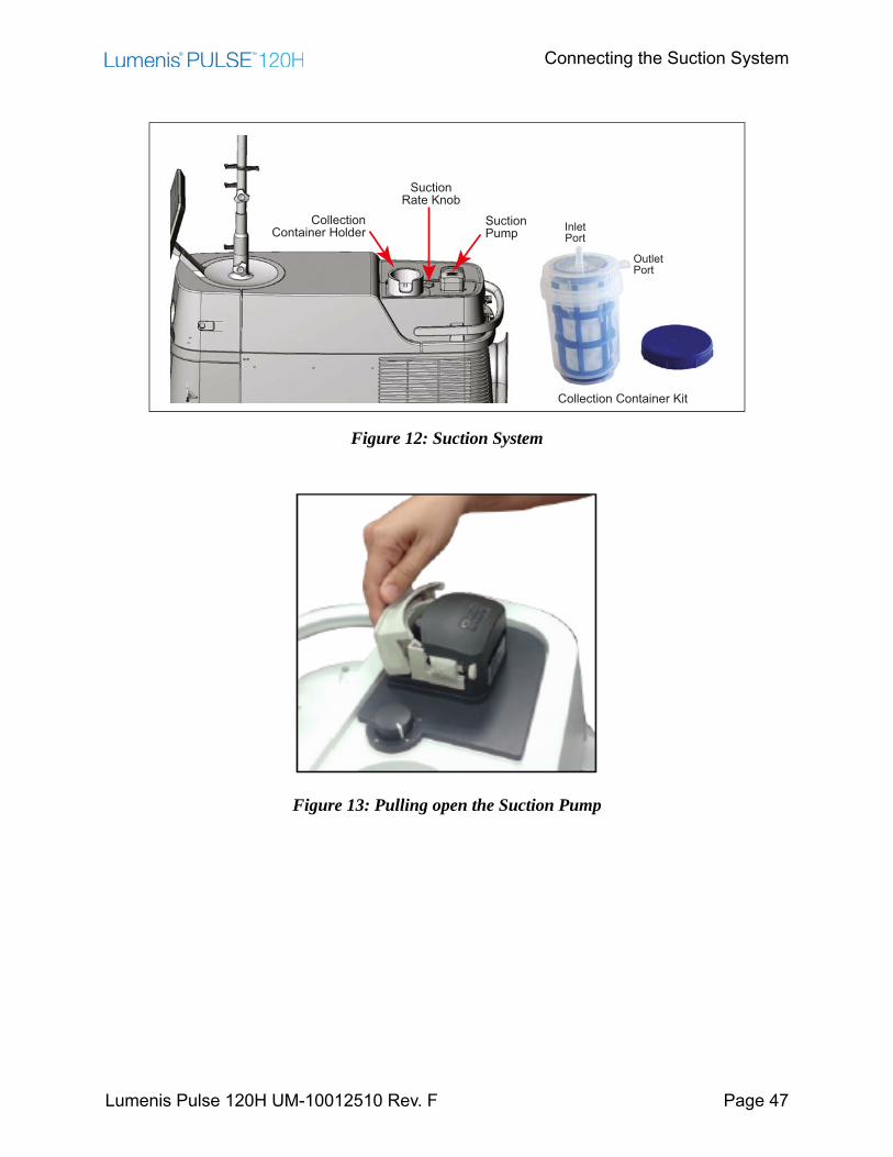
Refer to Figure 12
1. Insert a new collection container into the designed holder in the laser system.
2. The circulating nurse connects one side of a non-sterile drainage tube to the collection container's Outlet port. Connect the other side to the operating room's hazardous waste container.
WARNING:Ensure that the operating room's hazardous waste container (not supplied by Lumenis) is made of non-conductive material.
3. The scrub nurse connects one side of the sterile aspiration tube to the surgical accessory.
4. The scrub nurse hands off the other side of the sterile aspiration tube to circulating nurse. The circulating nurse connects this side of the tube to the collection container's Inlet port.
5. Pull open the suction pump (see Figure 13).
1. Optional purchase equipment
Connecting the Suction System
Lumenis Pulse 120H UM-10012510 Rev. F Page 47
Figure 12: Suction System
Figure 13: Pulling open the Suction Pump
CollectionContainer Holder
Collection Container Kit
SuctionPump
SuctionRate Knob
InletPort
OutletPort
Connecting the Suction System
Lumenis Pulse 120H UM-10012510 Rev. F Page 48
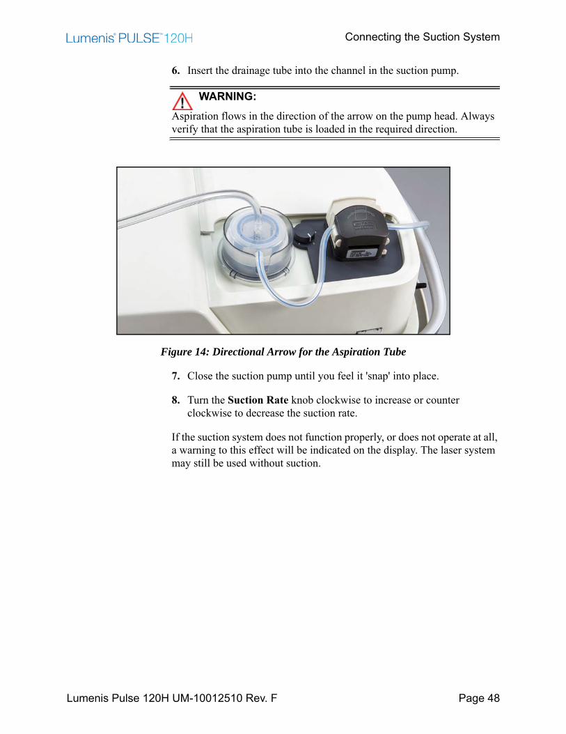
6. Insert the drainage tube into the channel in the suction pump.
WARNING:Aspiration flows in the direction of the arrow on the pump head. Always verify that the aspiration tube is loaded in the required direction.
Figure 14: Directional Arrow for the Aspiration Tube
7. Close the suction pump until you feel it 'snap' into place.
8. Turn the Suction Rate knob clockwise to increase or counter clockwise to decrease the suction rate.
If the suction system does not function properly, or does not operate at all, a warning to this effect will be indicated on the display. The laser system may still be used without suction.
Main System Screens
Lumenis Pulse 120H UM-10012510 Rev. F Page 49
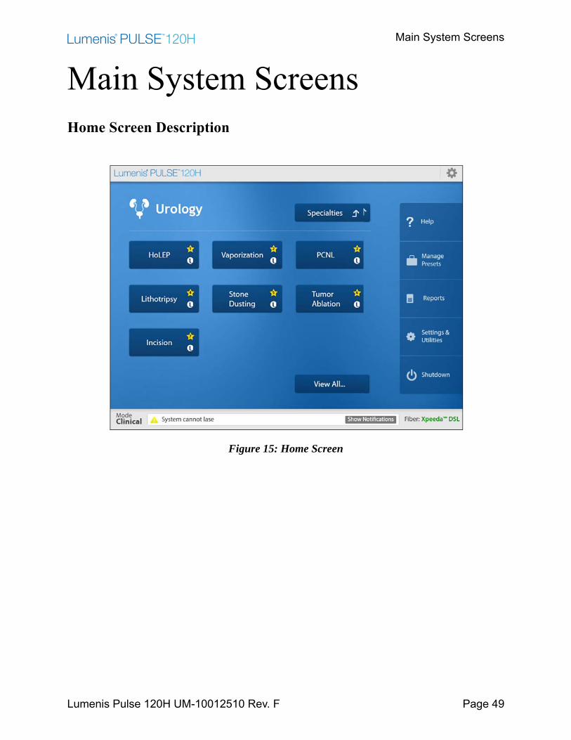
Main System ScreensHome Screen Description
Figure 15: Home Screen
Home Screen Description
Lumenis Pulse 120H UM-10012510 Rev. F Page 50
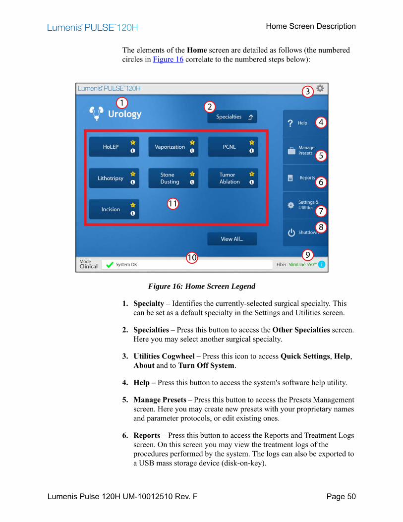
The elements of the Home screen are detailed as follows (the numbered circles in Figure 16 correlate to the numbered steps below):
Figure 16: Home Screen Legend
1. Specialty – Identifies the currently-selected surgical specialty. This can be set as a default specialty in the Settings and Utilities screen.
2. Specialties – Press this button to access the Other Specialties screen. Here you may select another surgical specialty.
3. Utilities Cogwheel – Press this icon to access Quick Settings, Help, About and to Turn Off System.
4. Help – Press this button to access the system's software help utility.
5. Manage Presets – Press this button to access the Presets Management screen. Here you may create new presets with your proprietary names and parameter protocols, or edit existing ones.
6. Reports – Press this button to access the Reports and Treatment Logs screen. On this screen you may view the treatment logs of the procedures performed by the system. The logs can also be exported to a USB mass storage device (disk-on-key).
4
11
213
9
8
7
6
5
10
Home Screen Description
Lumenis Pulse 120H UM-10012510 Rev. F Page 51
7. Settings & Utilities – Press this button to access the Settings and Utilities screen. Here you may configure or re- configure several of the system's functional utilities.
8. Shutdown – Press this button to perform an orderly shutdown of the system.
9. Fiber – Identifies the fiber connection status.
10. Notification Bar – Notifications and error messages will appear in this bar.
11. Presets – Lumenis Presets are hard-coded into the system software and are marked with the Lumenis logo. Hospital Presets are designed and entered to the system by the hospital's surgeons. Any settings entered or re-entered on the Main Treatment screen during a procedure, may be saved and named as a Hospital Preset.
The presets displayed on the Home screen are those defined as Favorites and are marked with a numbered star.
Press the View All… button to display all of the available presets, not only those defined as Favorites.
After you press the Preset button the system will transition to the Main Treatment screen.
Specialties Screen Description
Lumenis Pulse 120H UM-10012510 Rev. F Page 52
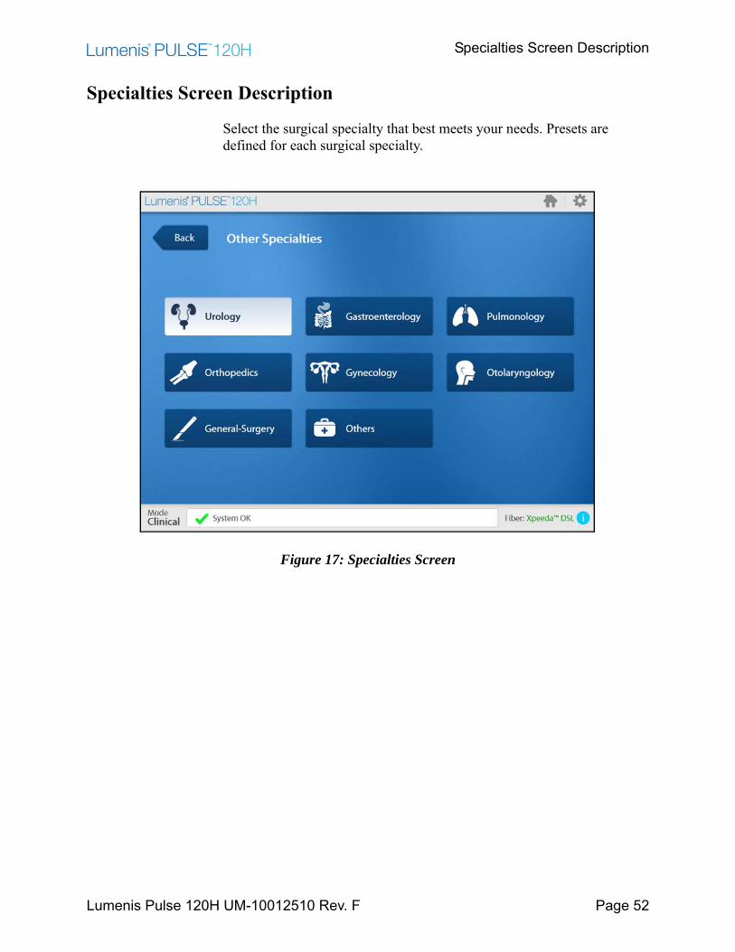
Specialties Screen Description
Select the surgical specialty that best meets your needs. Presets are defined for each surgical specialty.
Figure 17: Specialties Screen
Treatment Screen Description
Lumenis Pulse 120H UM-10012510 Rev. F Page 53
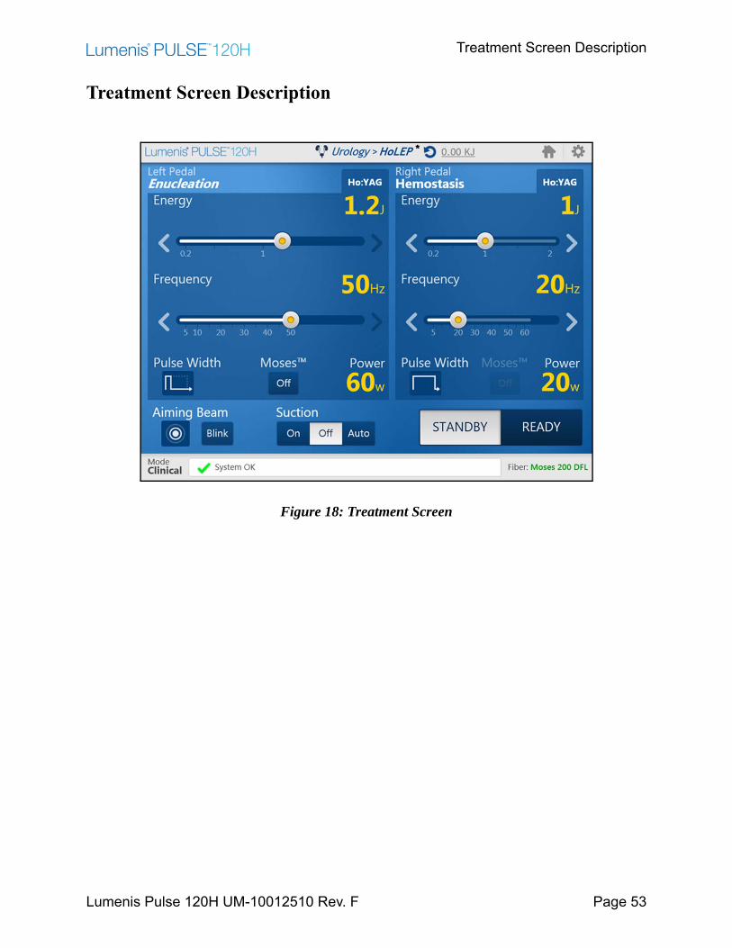
Treatment Screen Description
Figure 18: Treatment Screen
Treatment Screen Description
Lumenis Pulse 120H UM-10012510 Rev. F Page 54
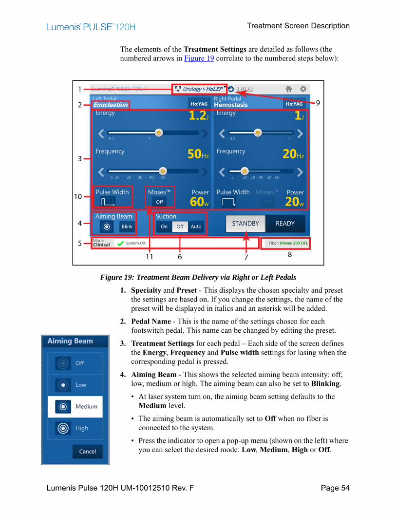
The elements of the Treatment Settings are detailed as follows (the numbered arrows in Figure 19 correlate to the numbered steps below):
Figure 19: Treatment Beam Delivery via Right or Left Pedals1. Specialty and Preset - This displays the chosen specialty and preset
the settings are based on. If you change the settings, the name of the preset will be displayed in italics and an asterisk will be added.
2. Pedal Name - This is the name of the settings chosen for each footswitch pedal. This name can be changed by editing the preset.
3. Treatment Settings for each pedal – Each side of the screen defines the Energy, Frequency and Pulse width settings for lasing when the corresponding pedal is pressed.
4. Aiming Beam - This shows the selected aiming beam intensity: off, low, medium or high. The aiming beam can also be set to Blinking.• At laser system turn on, the aiming beam setting defaults to the
Medium level.• The aiming beam is automatically set to Off when no fiber is
connected to the system.• Press the indicator to open a pop-up menu (shown on the left) where
you can select the desired mode: Low, Medium, High or Off.
4
2
1
3
87
5
9
10
11 6
Treatment Screen Description
Lumenis Pulse 120H UM-10012510 Rev. F Page 55
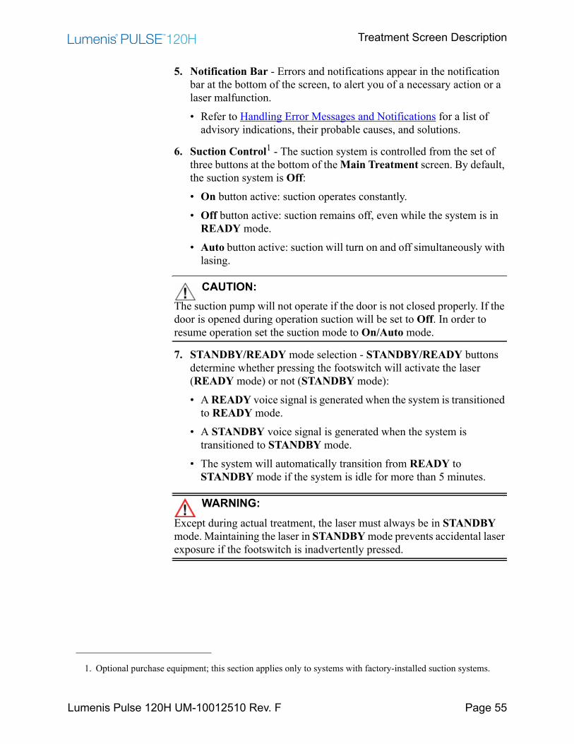
5. Notification Bar - Errors and notifications appear in the notification bar at the bottom of the screen, to alert you of a necessary action or a laser malfunction. • Refer to Handling Error Messages and Notifications for a list of
advisory indications, their probable causes, and solutions.
6. Suction Control1 - The suction system is controlled from the set of three buttons at the bottom of the Main Treatment screen. By default, the suction system is Off:• On button active: suction operates constantly.• Off button active: suction remains off, even while the system is in
READY mode.• Auto button active: suction will turn on and off simultaneously with
lasing.
CAUTION:The suction pump will not operate if the door is not closed properly. If the door is opened during operation suction will be set to Off. In order to resume operation set the suction mode to On/Auto mode.
7. STANDBY/READY mode selection - STANDBY/READY buttons determine whether pressing the footswitch will activate the laser (READY mode) or not (STANDBY mode):• A READY voice signal is generated when the system is transitioned
to READY mode.• A STANDBY voice signal is generated when the system is
transitioned to STANDBY mode.• The system will automatically transition from READY to
STANDBY mode if the system is idle for more than 5 minutes.
WARNING:Except during actual treatment, the laser must always be in STANDBY mode. Maintaining the laser in STANDBY mode prevents accidental laser exposure if the footswitch is inadvertently pressed.
1. Optional purchase equipment; this section applies only to systems with factory-installed suction systems.

Treatment Screen Description
Lumenis Pulse 120H UM-10012510 Rev. F Page 56
8. Fiber Status Area - Certain Lumenis SIS fiber delivery systems for the Lumenis Pulse 120H are designed to allow several surgical treatments, while others are limited to only one treatment. When a fiber is connected, the system immediately knows:• How many treatments have been performed with the fiber.• How many treatments are recommended before you replace the
fiber.• If all allocated treatments are exhausted and the fiber is expired.• If the delivery system has any power limitations.Every time the fiber is connected to the system, the fiber status area will indicate the fiber mode. There are four fiber modes, color-coded according to the status:• Normal mode (green) – The fiber is working within operational
limits.• Grace mode (orange) – You are advised to replace the fiber,
because it exceeded recommended usage. However, you can continue to work. The Fiber exceeded recommend # of uses. It is advised to replace the fiber error message will also appear inside the notification bar.
• Fiber expired (red) – You cannot work with this fiber. The Fiber expired recoverable error message will also appear inside the notification bar.
• Unrecognized Fiber (red) – You cannot work with this fiber. The Lumenis SIS fiber not detected recoverable error message will also appear inside the notification bar.
By pressing the icon in the Fiber Status Area, additional information regarding the number of sessions used and the number of recommended sessions for the fiber in use will be displayed.
NOTE:For detailed information on the number of treatments each Lumenis fiber is designed to perform, refer to the instruction guide delivered with the fiber.
Treatment Screen Description
Lumenis Pulse 120H UM-10012510 Rev. F Page 57
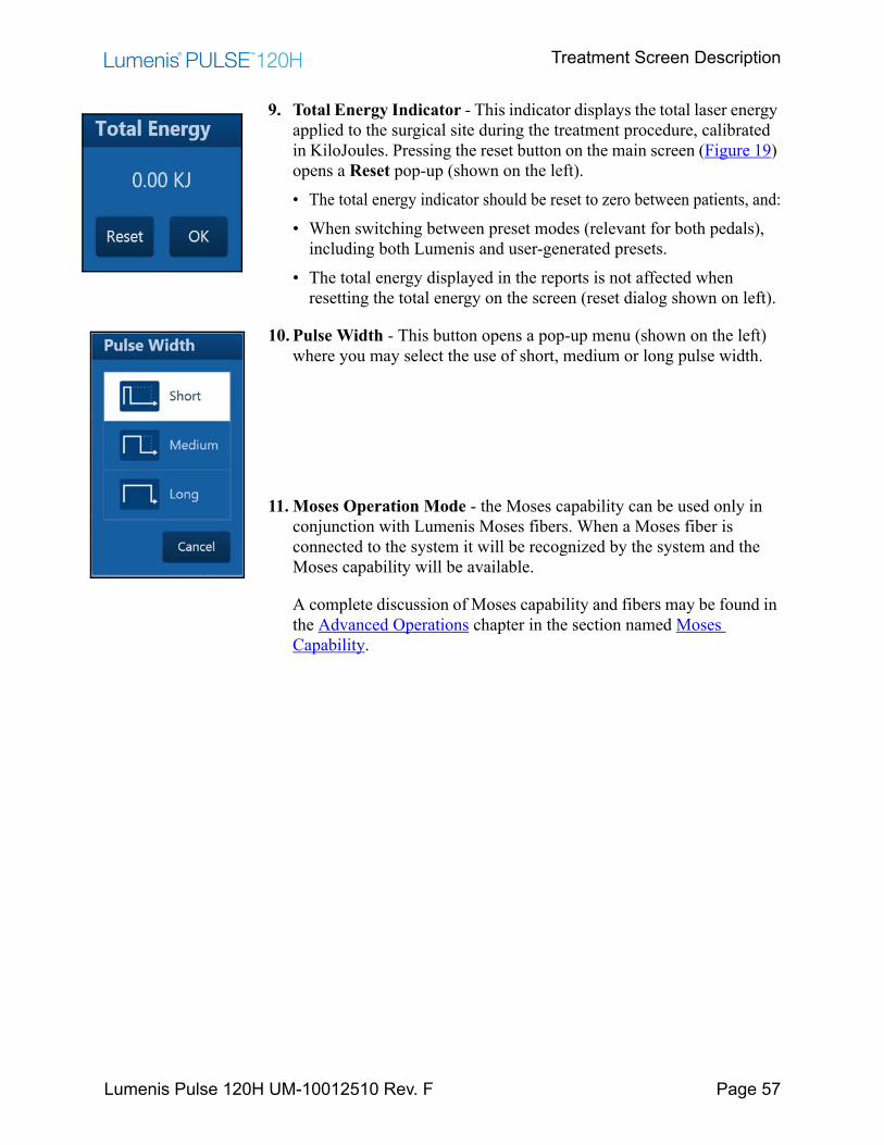
9. Total Energy Indicator - This indicator displays the total laser energy applied to the surgical site during the treatment procedure, calibrated in KiloJoules. Pressing the reset button on the main screen (Figure 19) opens a Reset pop-up (shown on the left).• The total energy indicator should be reset to zero between patients, and:• When switching between preset modes (relevant for both pedals),
including both Lumenis and user-generated presets.• The total energy displayed in the reports is not affected when
resetting the total energy on the screen (reset dialog shown on left).
10. Pulse Width - This button opens a pop-up menu (shown on the left) where you may select the use of short, medium or long pulse width.
11. Moses Operation Mode - the Moses capability can be used only in conjunction with Lumenis Moses fibers. When a Moses fiber is connected to the system it will be recognized by the system and the Moses capability will be available.
A complete discussion of Moses capability and fibers may be found in the Advanced Operations chapter in the section named Moses Capability.
Laser Emission Indication
Lumenis Pulse 120H UM-10012510 Rev. F Page 58
Laser Emission Indication
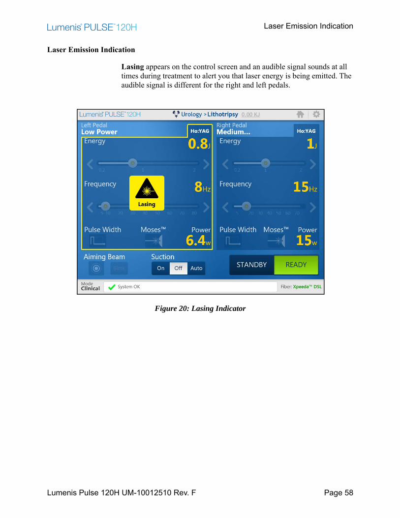
Lasing appears on the control screen and an audible signal sounds at all times during treatment to alert you that laser energy is being emitted. The audible signal is different for the right and left pedals.
Figure 20: Lasing Indicator

Normal Operation
Lumenis Pulse 120H UM-10012510 Rev. F Page 59
Normal OperationEmergency Stop Button
In an emergency, press the laser emergency stop button on the front of the laser to immediately disable emission of the laser energy.
Figure 21: Location of the Emergency Button
NOTE:When the main power cable is connected to the electrical source, some internal circuits remain energized. To de-energize all internal circuits, set the laser's main circuit breaker to the Off position, and turn off the main electrical service (wall circuit breaker).
Verification of Connections
1. Verify that the delivery system is properly connected to the laser.
WARNING:• When using a fiber optic delivery device, always inspect the fiber
optic cable to ensure that it has not been kinked, punctured, fractured, or otherwise damaged. The fiber optic cable may be damaged if stepped on, pulled, left lying in a vulnerable position, kinked, or tightly coiled.
• Do not clamp the cable with a hemostat or other instruments. • If sterile tape is used, always remove the tape before lifting the cable.
A damaged fiber optic cable may cause accidental laser exposure or injury to the treatment room personnel or patient, and/or fire in the treatment room.
2. If desired by the surgical team, connect the surgical accessory to the suction system.
Powering on the System
Lumenis Pulse 120H UM-10012510 Rev. F Page 60
3. Verify that the footswitch is properly connected.
4. Verify that all persons in the operating room have appropriate laser safety eyewear.
Powering on the System
1. Ensure that keyswitch is in the Open position.
2. Press the main On/Off button and hold it for one full second, then release.
• If the keyswitch is in the Closed position, the system will only allow you to access reports. To turn the laser on, you will need to restart while the keyswitch is in the Open position.
• The system self-test and warm-up procedure takes approximately one minute to complete. A progress bar appears on the control screen during the self-test and warm-up procedure.
NOTE:If any fault conditions are encountered during laser start-up and self-test, error messages can appear in pop-up windows or in the notification area on the control screen. Refer to “Handling Error Messages and Notifications”.
Selecting the Treatment
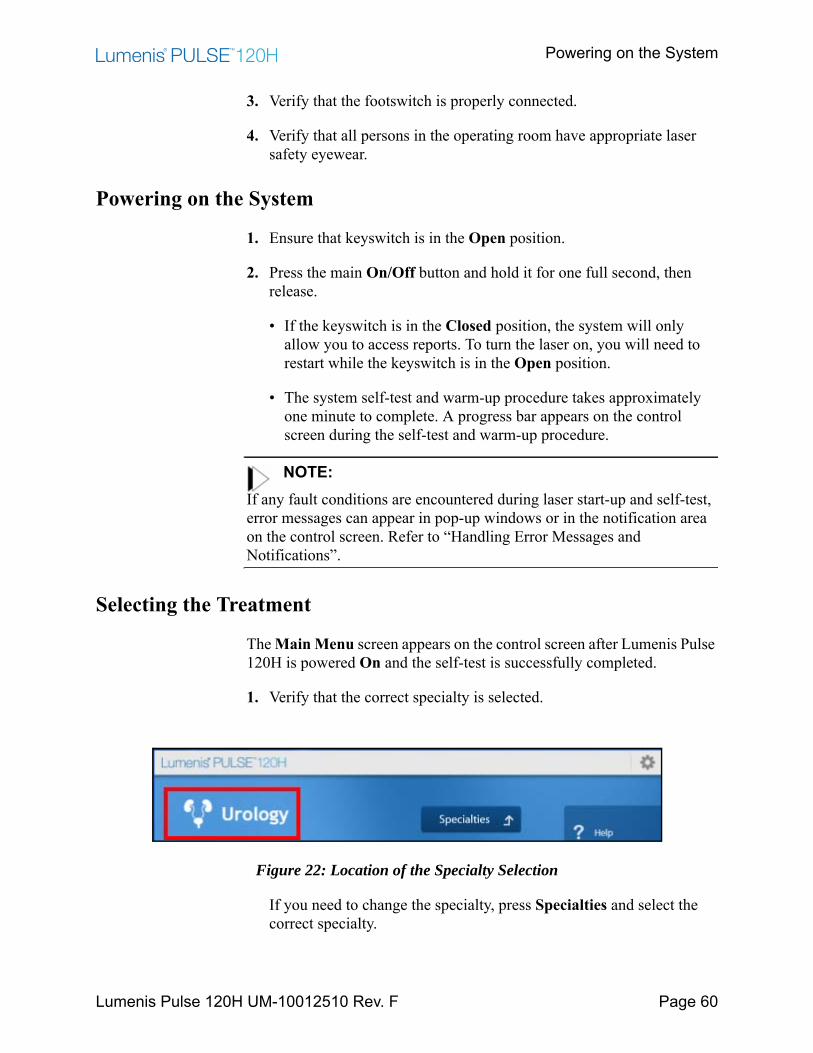
The Main Menu screen appears on the control screen after Lumenis Pulse 120H is powered On and the self-test is successfully completed.
1. Verify that the correct specialty is selected.
Figure 22: Location of the Specialty Selection
If you need to change the specialty, press Specialties and select the correct specialty.
Selecting the Treatment
Lumenis Pulse 120H UM-10012510 Rev. F Page 61
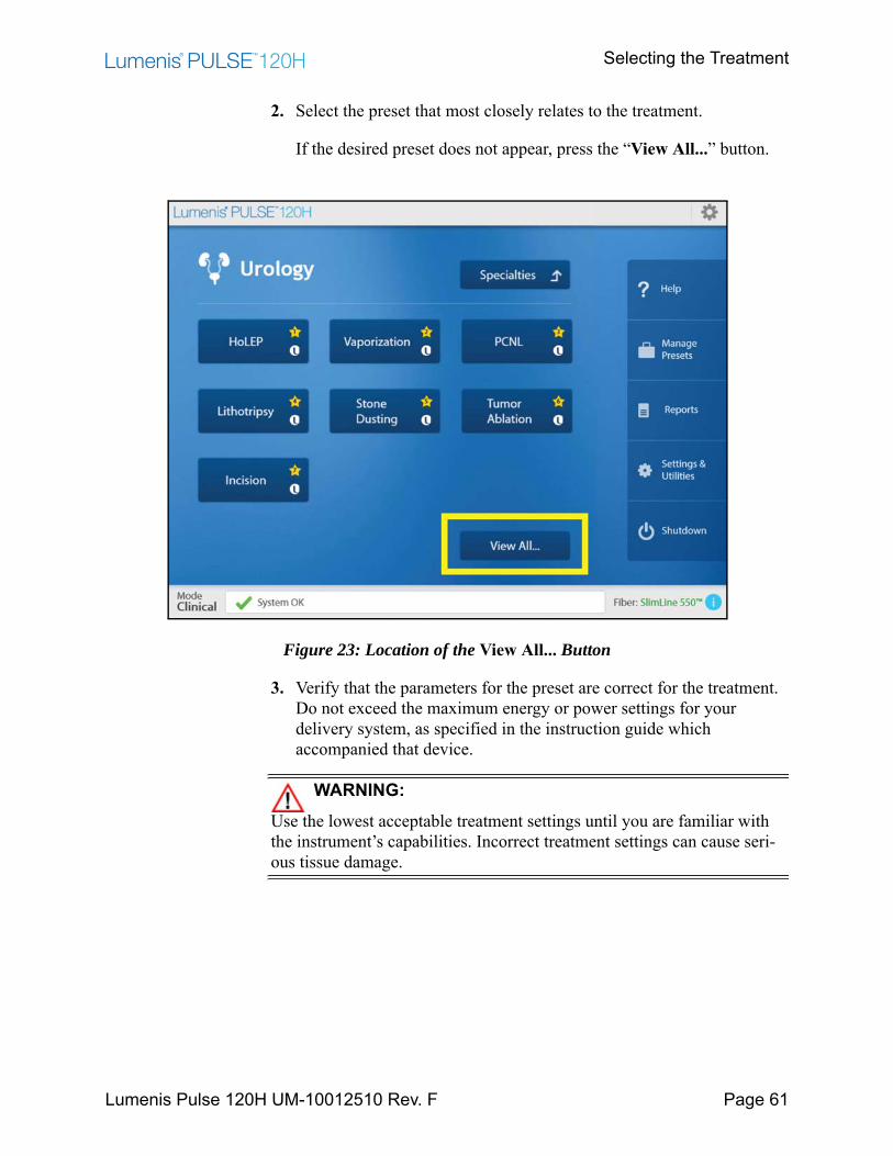
2. Select the preset that most closely relates to the treatment.
If the desired preset does not appear, press the “View All...” button.
Figure 23: Location of the View All... Button
3. Verify that the parameters for the preset are correct for the treatment. Do not exceed the maximum energy or power settings for your delivery system, as specified in the instruction guide which accompanied that device.
WARNING:Use the lowest acceptable treatment settings until you are familiar with the instrument’s capabilities. Incorrect treatment settings can cause seri-ous tissue damage.
Selecting the Treatment
Lumenis Pulse 120H UM-10012510 Rev. F Page 62
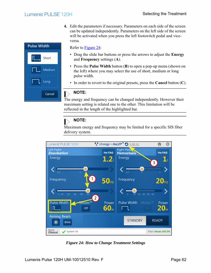
4. Edit the parameters if necessary. Parameters on each side of the screen can be updated independently. Parameters on the left side of the screen will be activated when you press the left footswitch pedal and vice-versa.Refer to Figure 24:• Drag the slide bar buttons or press the arrows to adjust the Energy
and Frequency settings (A).• Press the Pulse Width button (B) to open a pop-up menu (shown on
the left) where you may select the use of short, medium or long pulse width.
• In order to revert to the original presets, press the Cancel button (C).
NOTE:The energy and frequency can be changed independently. However their maximum setting is related one to the other. This limitation will be reflected in the length of the highlighted bar.
NOTE:Maximum energy and frequency may be limited for a specific SIS fiber delivery system.
Figure 24: How to Change Treatment Settings

Starting Laser Treatment
Lumenis Pulse 120H UM-10012510 Rev. F Page 63
Starting Laser Treatment
1. Turn on the aiming beam, and set it to high intensity.
2. Test the integrity of the aiming beam.
Hold a non-reflective surface, such as a tongue depressor, in front of the fiber tip. For side-emission delivery systems, hold the non-reflective surface in front of the side opening at the fiber tip.
A green spot, the aiming beam, should appear on the surface. If the aiming beam is weak, check that it is set to high intensity. If the aiming beam is still weak, verify that the laser debris shield and delivery system laser connector are not damaged. Refer to “Inspect / Replace the Debris Shield” and the section in the appropriate delivery system instruction guide (look under “Inspect the laser connector”).
WARNING:• Do not use the delivery system if the aiming beam is set to high
intensity and is still weak or not visible; the fiber optic cable may be damaged. A damaged cable may cause accidental laser exposure or injury to the treatment room personnel or patient, and/or fire in the treatment room.
• Do not use the laser or delivery system if the aiming beam has not been verified. Verifying the aiming beam integrity is extremely important for the safe operation of your laser equipment.
• Do not use the laser or delivery system if the aiming beam is not visible. Operating the laser without the aiming beam may result in laser exposure to non-target tissue and possible injury.
NOTE:When using the delivery system with an endoscopic camera, lower the intensity of the camera light if the aiming beam is weak or not visible. Doing so will not affect visibility at the treatment site, since the camera compensates for the lower level of light.
3. Position the aiming beam on the target tissue.
Starting Laser Treatment
Lumenis Pulse 120H UM-10012510 Rev. F Page 64
4. Press the Ready button to switch to Ready mode.
WARNING:Always verify your parameter settings on the screen before setting the system to Ready mode.
NOTE:A Ready voice signal is generated when the system is transitioned to Ready mode. A Standby voice signal is generated when the system is transitioned to Standby mode. The voice signals are generated in the language that was selected in the “Changing Language” section. The “Adjusting Volume and Sound” section describes how to adjust the volume or switch off the voice signals.
5. Verify that your foot is on the appropriate footswitch pedal for the left-side or right-side parameter settings on the screen.
6. Press the footswitch that corresponds to the desired set of parameters to deliver the treatment beam.
As the laser delivers the treatment beam, Lasing appears on the control screen and an audible signal sounds to alert you that laser energy is being emitted. The audible signal is different for the right and left pedals.
7. Use the footpedal Ready/Standby button (on the top of the footswitch) to switch between Ready and Standby modes.
8. If surgery is interrupted, set the laser to STANDBY mode to disable the footswitch.
WARNING:Always set the laser to Standby mode when it is not in use to avoid unin-tended laser emission.
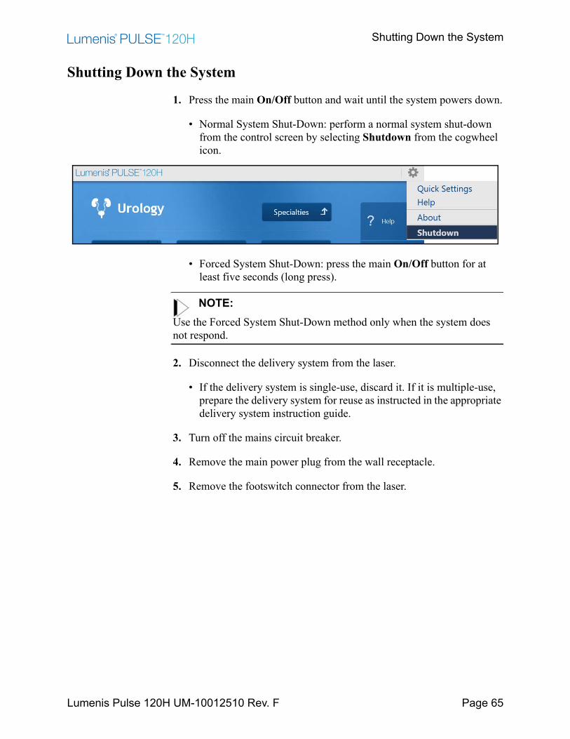
Shutting Down the System
Lumenis Pulse 120H UM-10012510 Rev. F Page 65
Shutting Down the System
1. Press the main On/Off button and wait until the system powers down.
• Normal System Shut-Down: perform a normal system shut-down from the control screen by selecting Shutdown from the cogwheel icon.
• Forced System Shut-Down: press the main On/Off button for at least five seconds (long press).
NOTE:Use the Forced System Shut-Down method only when the system does not respond.
2. Disconnect the delivery system from the laser.
• If the delivery system is single-use, discard it. If it is multiple-use, prepare the delivery system for reuse as instructed in the appropriate delivery system instruction guide.
3. Turn off the mains circuit breaker.
4. Remove the main power plug from the wall receptacle.
5. Remove the footswitch connector from the laser.
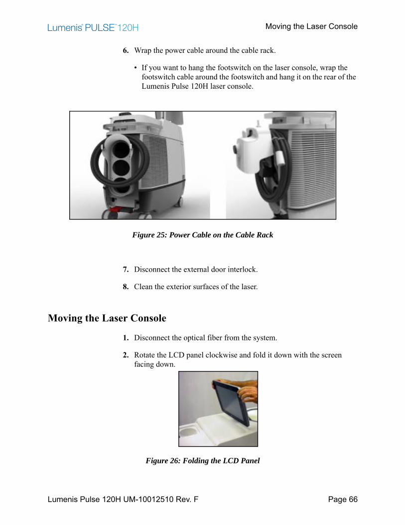
Moving the Laser Console
Lumenis Pulse 120H UM-10012510 Rev. F Page 66
6. Wrap the power cable around the cable rack.
• If you want to hang the footswitch on the laser console, wrap the footswitch cable around the footswitch and hang it on the rear of the Lumenis Pulse 120H laser console.
Figure 25: Power Cable on the Cable Rack
7. Disconnect the external door interlock.
8. Clean the exterior surfaces of the laser.
Moving the Laser Console
1. Disconnect the optical fiber from the system.
2. Rotate the LCD panel clockwise and fold it down with the screen facing down.
Figure 26: Folding the LCD Panel
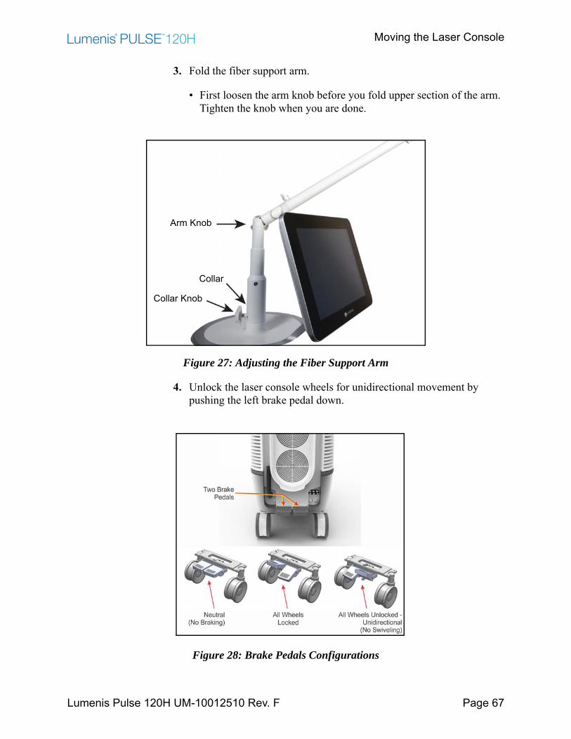
Moving the Laser Console
Lumenis Pulse 120H UM-10012510 Rev. F Page 67
3. Fold the fiber support arm.
• First loosen the arm knob before you fold upper section of the arm. Tighten the knob when you are done.
Figure 27: Adjusting the Fiber Support Arm
4. Unlock the laser console wheels for unidirectional movement by pushing the left brake pedal down.
Figure 28: Brake Pedals Configurations
Arm Knob
Collar
Collar Knob
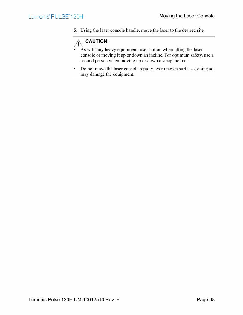
Moving the Laser Console
Lumenis Pulse 120H UM-10012510 Rev. F Page 68
5. Using the laser console handle, move the laser to the desired site.
CAUTION:• As with any heavy equipment, use caution when tilting the laser
console or moving it up or down an incline. For optimum safety, use a second person when moving up or down a steep incline.
• Do not move the laser console rapidly over uneven surfaces; doing so may damage the equipment.
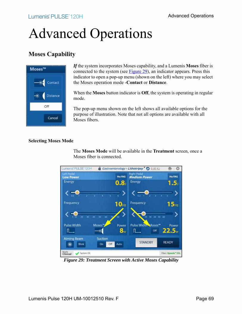
Advanced Operations
Lumenis Pulse 120H UM-10012510 Rev. F Page 69
Advanced OperationsMoses Capability
If the system incorporates Moses capability, and a Lumenis Moses fiber is connected to the system (see Figure 29), an indicator appears. Press this indicator to open a pop-up menu (shown on the left) where you may select the Moses operation mode -Contact or Distance.
When the Moses button indicator is Off, the system is operating in regular mode.
The pop-up menu shown on the left shows all available options for the purpose of illustration. Note that not all options are available with all Moses fibers.
Selecting Moses Mode
The Moses Mode will be available in the Treatment screen, once a Moses fiber is connected.
Figure 29: Treatment Screen with Active Moses Capability
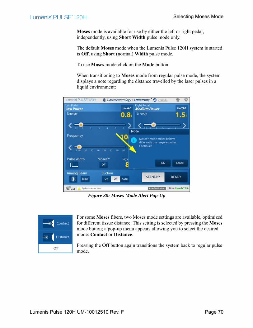
Selecting Moses Mode
Lumenis Pulse 120H UM-10012510 Rev. F Page 70
Moses mode is available for use by either the left or right pedal, independently, using Short Width pulse mode only.
The default Moses mode when the Lumenis Pulse 120H system is started is Off, using Short (normal) Width pulse mode.
To use Moses mode click on the Mode button.
When transitioning to Moses mode from regular pulse mode, the system displays a note regarding the distance travelled by the laser pulses in a liquid environment:
Figure 30: Moses Mode Alert Pop-Up
For some Moses fibers, two Moses mode settings are available, optimized for different tissue distance. This setting is selected by pressing the Moses mode button; a pop-up menu appears allowing you to select the desired mode: Contact or Distance.
Pressing the Off button again transitions the system back to regular pulse mode.
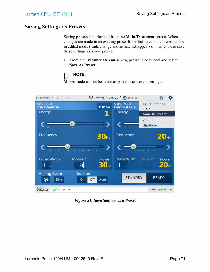
Saving Settings as Presets
Lumenis Pulse 120H UM-10012510 Rev. F Page 71
Saving Settings as Presets
Saving presets is performed from the Main Treatment screen. When changes are made to an existing preset from that screen, the preset will be in edited mode (fonts change and an asterisk appears). Then you can save these settings as a new preset.
1. From the Treatment Menu screen, press the cogwheel and select Save As Preset.
NOTE:Moses mode cannot be saved as part of the present settings.
Figure 31: Save Settings as a Preset
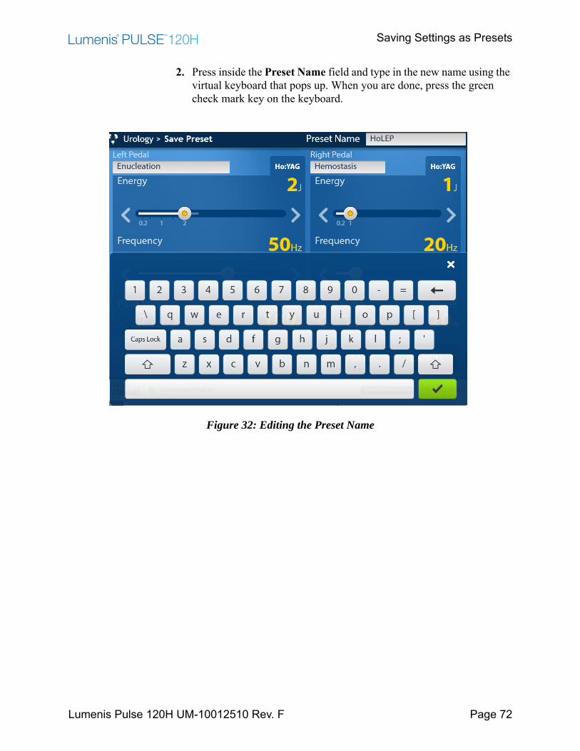
Saving Settings as Presets
Lumenis Pulse 120H UM-10012510 Rev. F Page 72
2. Press inside the Preset Name field and type in the new name using the virtual keyboard that pops up. When you are done, press the green check mark key on the keyboard.
Figure 32: Editing the Preset Name
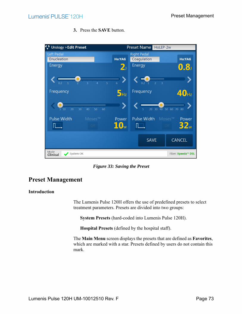
Preset Management
Lumenis Pulse 120H UM-10012510 Rev. F Page 73
3. Press the SAVE button.
Figure 33: Saving the Preset
Preset Management
Introduction
The Lumenis Pulse 120H offers the use of predefined presets to select treatment parameters. Presets are divided into two groups:
System Presets (hard-coded into Lumenis Pulse 120H).
Hospital Presets (defined by the hospital staff).
The Main Menu screen displays the presets that are defined as Favorites, which are marked with a star. Presets defined by users do not contain this mark.

Introduction
Lumenis Pulse 120H UM-10012510 Rev. F Page 74
You can save any settings defined on the Main Treatment screen during a procedure as a Hospital Preset.
Figure 34: Manage Presets Screen
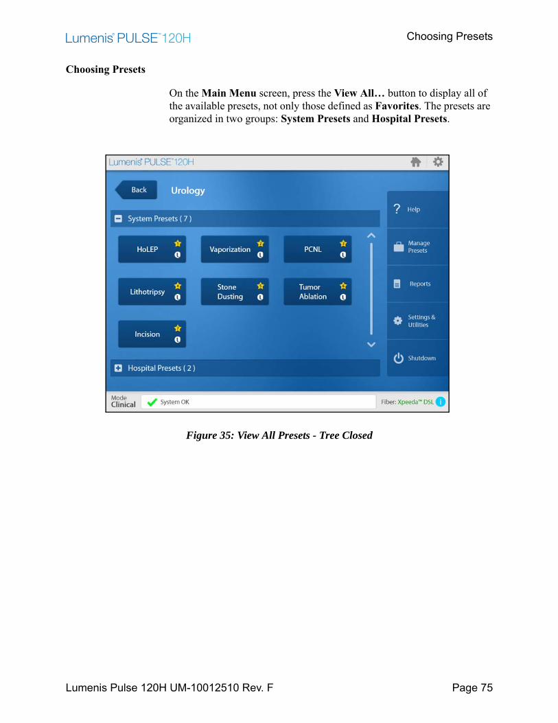
Choosing Presets
Lumenis Pulse 120H UM-10012510 Rev. F Page 75
Choosing Presets
On the Main Menu screen, press the View All… button to display all of the available presets, not only those defined as Favorites. The presets are organized in two groups: System Presets and Hospital Presets.
Figure 35: View All Presets - Tree Closed
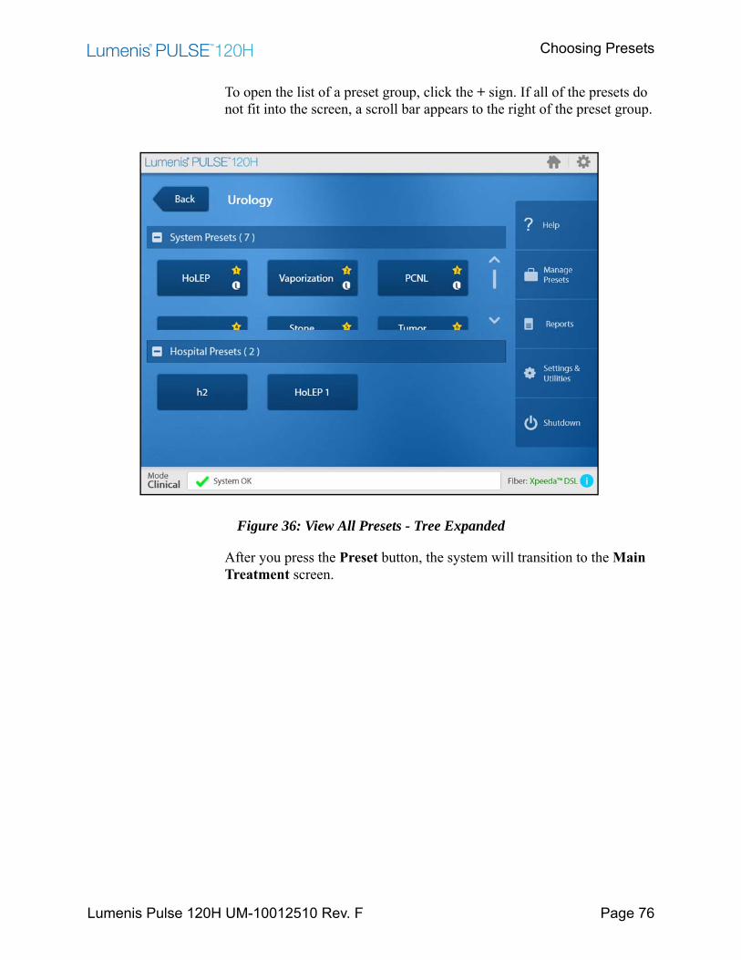
Choosing Presets
Lumenis Pulse 120H UM-10012510 Rev. F Page 76
To open the list of a preset group, click the + sign. If all of the presets do not fit into the screen, a scroll bar appears to the right of the preset group.
Figure 36: View All Presets - Tree Expanded
After you press the Preset button, the system will transition to the Main Treatment screen.
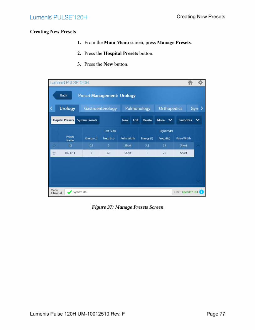
Creating New Presets
Lumenis Pulse 120H UM-10012510 Rev. F Page 77
Creating New Presets
1. From the Main Menu screen, press Manage Presets.
2. Press the Hospital Presets button.
3. Press the New button.
Figure 37: Manage Presets Screen
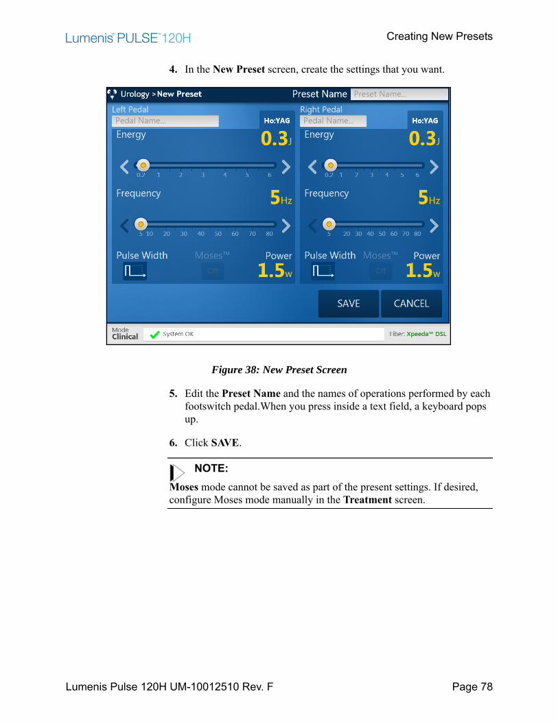
Creating New Presets
Lumenis Pulse 120H UM-10012510 Rev. F Page 78
4. In the New Preset screen, create the settings that you want.
Figure 38: New Preset Screen
5. Edit the Preset Name and the names of operations performed by each footswitch pedal.When you press inside a text field, a keyboard pops up.
6. Click SAVE.
NOTE:Moses mode cannot be saved as part of the present settings. If desired, configure Moses mode manually in the Treatment screen.
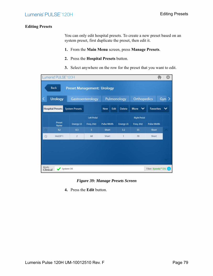
Editing Presets
Lumenis Pulse 120H UM-10012510 Rev. F Page 79
Editing Presets
You can only edit hospital presets. To create a new preset based on an system preset, first duplicate the preset, then edit it.
1. From the Main Menu screen, press Manage Presets.
2. Press the Hospital Presets button.
3. Select anywhere on the row for the preset that you want to edit.
Figure 39: Manage Presets Screen
4. Press the Edit button.
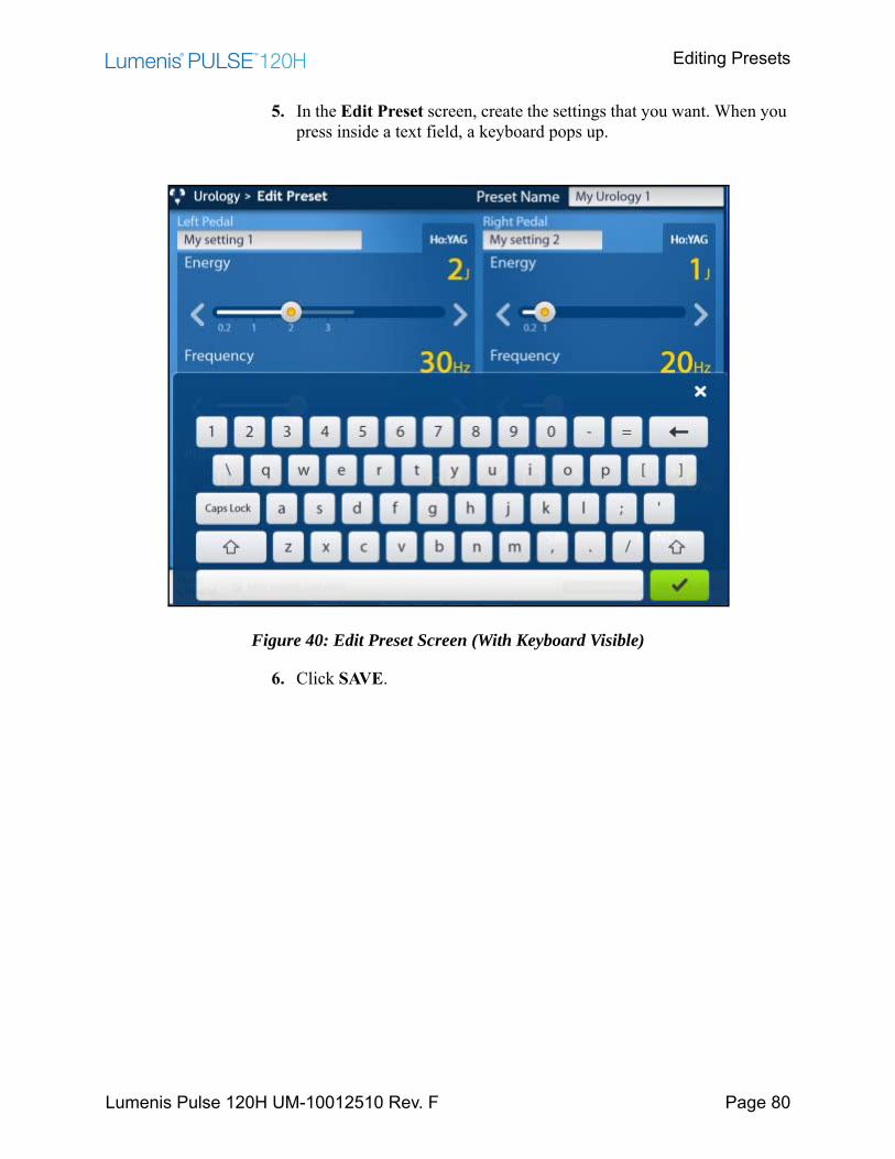
Editing Presets
Lumenis Pulse 120H UM-10012510 Rev. F Page 80
5. In the Edit Preset screen, create the settings that you want. When you press inside a text field, a keyboard pops up.
Figure 40: Edit Preset Screen (With Keyboard Visible)
6. Click SAVE.
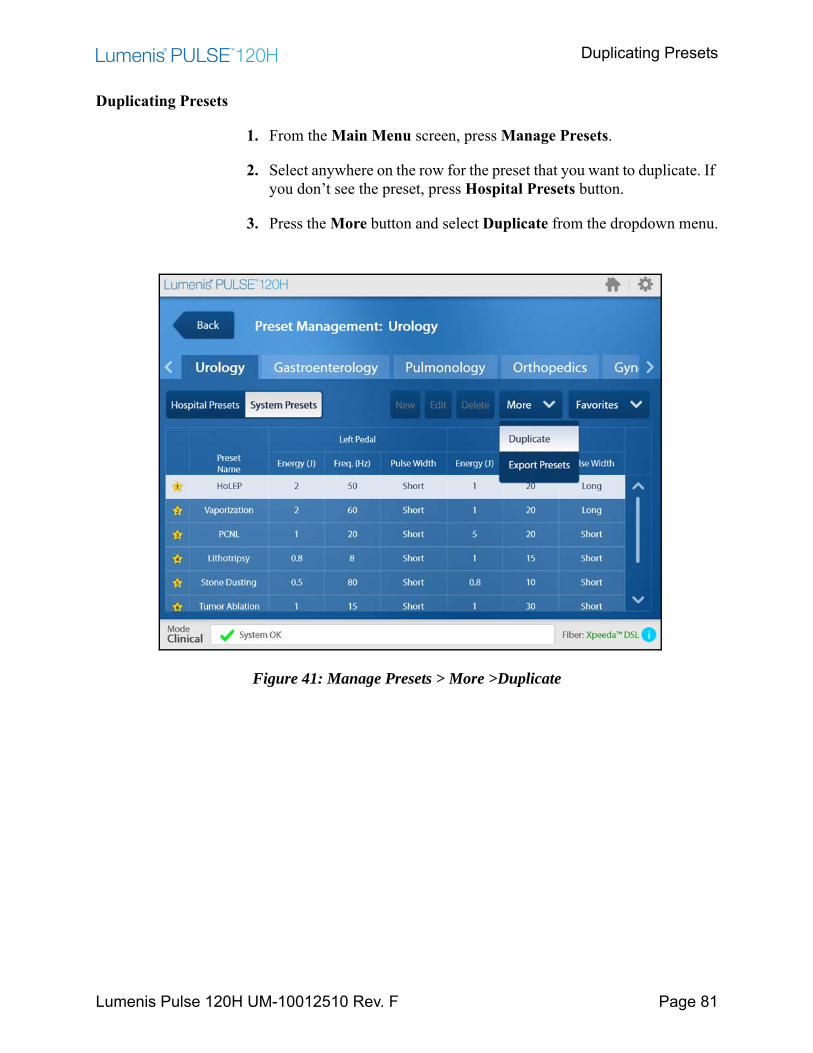
Duplicating Presets
Lumenis Pulse 120H UM-10012510 Rev. F Page 81
Duplicating Presets
1. From the Main Menu screen, press Manage Presets.
2. Select anywhere on the row for the preset that you want to duplicate. If you don’t see the preset, press Hospital Presets button.
3. Press the More button and select Duplicate from the dropdown menu.
Figure 41: Manage Presets > More >Duplicate
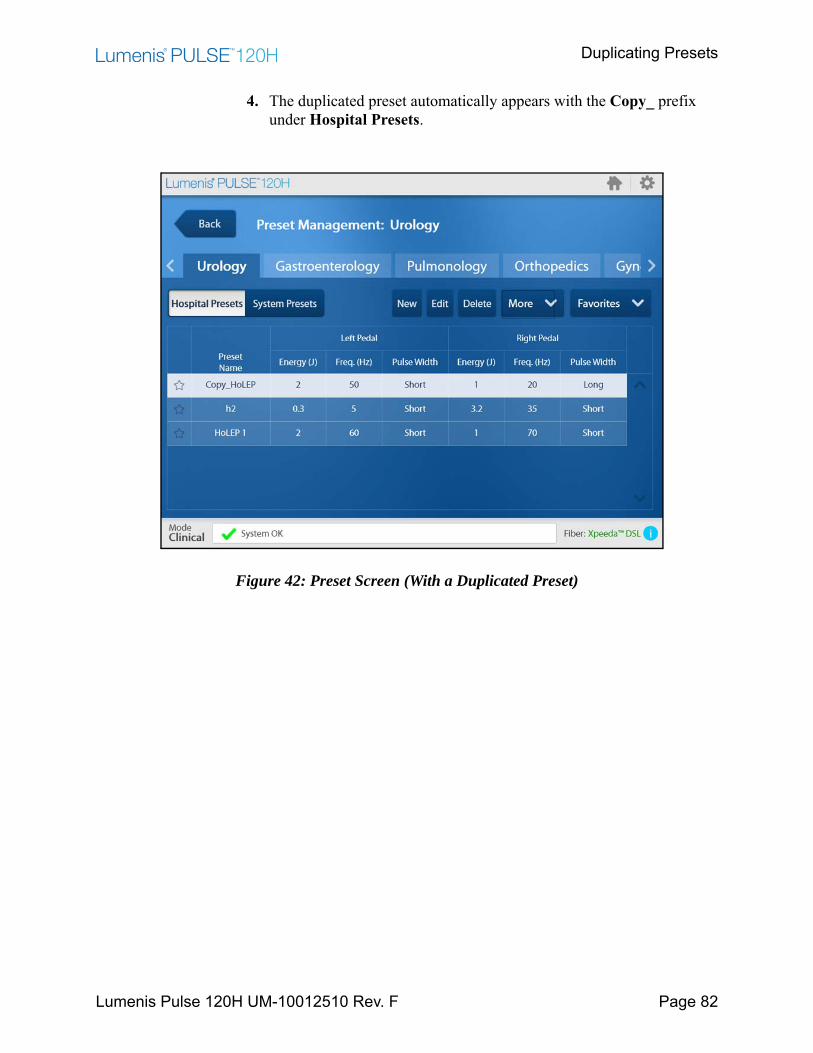
Duplicating Presets
Lumenis Pulse 120H UM-10012510 Rev. F Page 82
4. The duplicated preset automatically appears with the Copy_ prefix under Hospital Presets.
Figure 42: Preset Screen (With a Duplicated Preset)
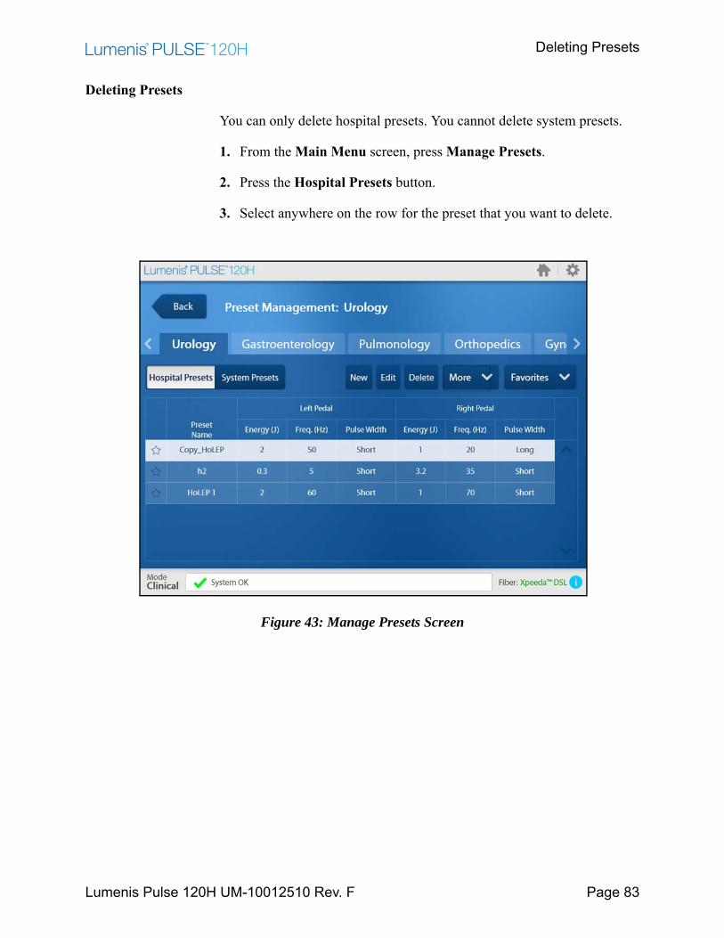
Deleting Presets
Lumenis Pulse 120H UM-10012510 Rev. F Page 83
Deleting Presets
You can only delete hospital presets. You cannot delete system presets.
1. From the Main Menu screen, press Manage Presets.
2. Press the Hospital Presets button.
3. Select anywhere on the row for the preset that you want to delete.
Figure 43: Manage Presets Screen
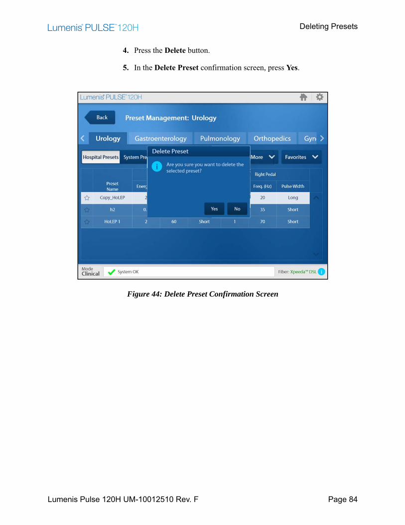
Deleting Presets
Lumenis Pulse 120H UM-10012510 Rev. F Page 84
4. Press the Delete button.
5. In the Delete Preset confirmation screen, press Yes.
Figure 44: Delete Preset Confirmation Screen
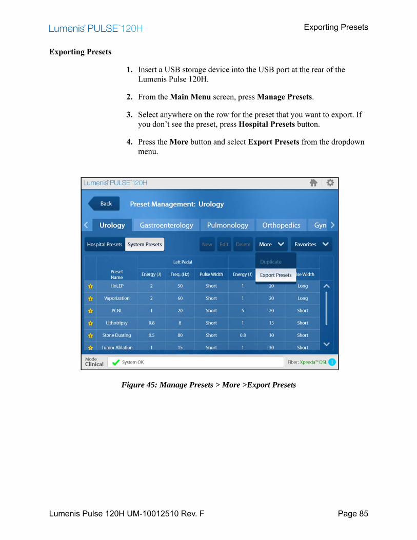
Exporting Presets
Lumenis Pulse 120H UM-10012510 Rev. F Page 85
Exporting Presets
1. Insert a USB storage device into the USB port at the rear of the Lumenis Pulse 120H.
2. From the Main Menu screen, press Manage Presets.
3. Select anywhere on the row for the preset that you want to export. If you don’t see the preset, press Hospital Presets button.
4. Press the More button and select Export Presets from the dropdown menu.
Figure 45: Manage Presets > More >Export Presets
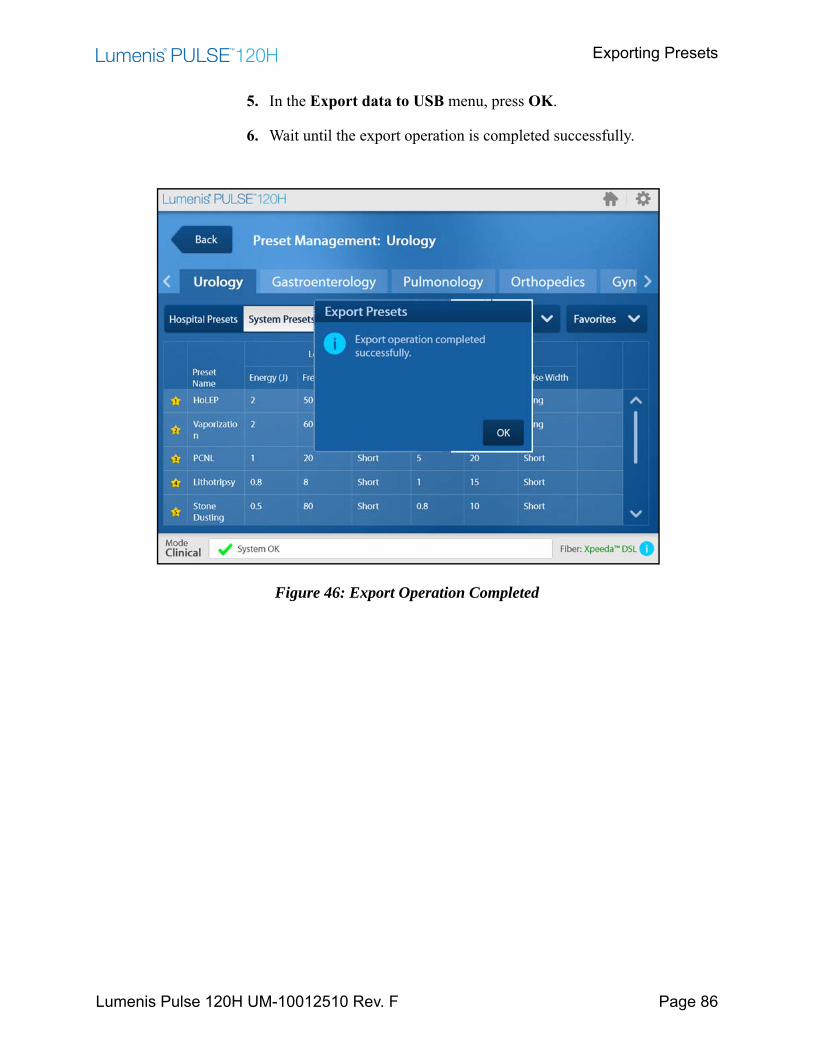
Exporting Presets
Lumenis Pulse 120H UM-10012510 Rev. F Page 86
5. In the Export data to USB menu, press OK.
6. Wait until the export operation is completed successfully.
Figure 46: Export Operation Completed
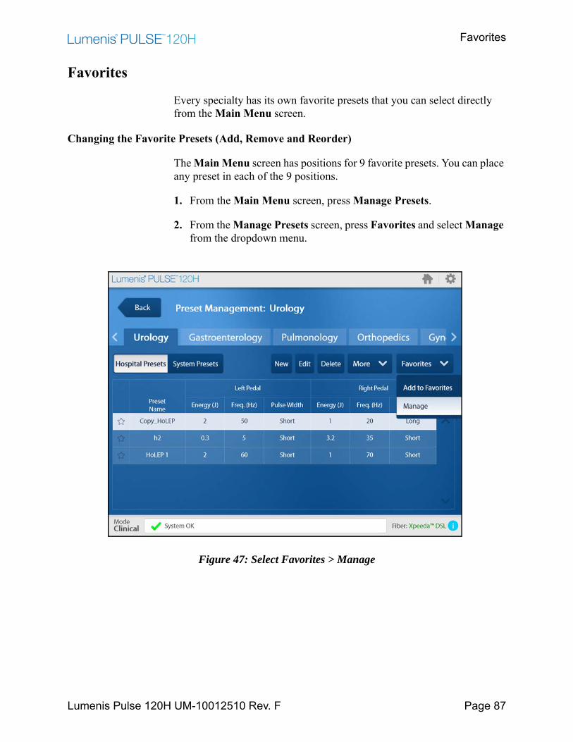
Favorites
Lumenis Pulse 120H UM-10012510 Rev. F Page 87
Favorites
Every specialty has its own favorite presets that you can select directly from the Main Menu screen.
Changing the Favorite Presets (Add, Remove and Reorder)
The Main Menu screen has positions for 9 favorite presets. You can place any preset in each of the 9 positions.
1. From the Main Menu screen, press Manage Presets.
2. From the Manage Presets screen, press Favorites and select Manage from the dropdown menu.
Figure 47: Select Favorites > Manage

Changing the Favorite Presets (Add, Remove and Reorder)
Lumenis Pulse 120H UM-10012510 Rev. F Page 88
3. To add an existing, non-favorite preset to your list of favorites, press the Add a favorite button.
Figure 48: Select Favorites > Manage
4. Press the non-favorite preset PCNL (for example) to select it. Press the Add button to add it to the favorites.
Figure 49: Add a Favorite Screen
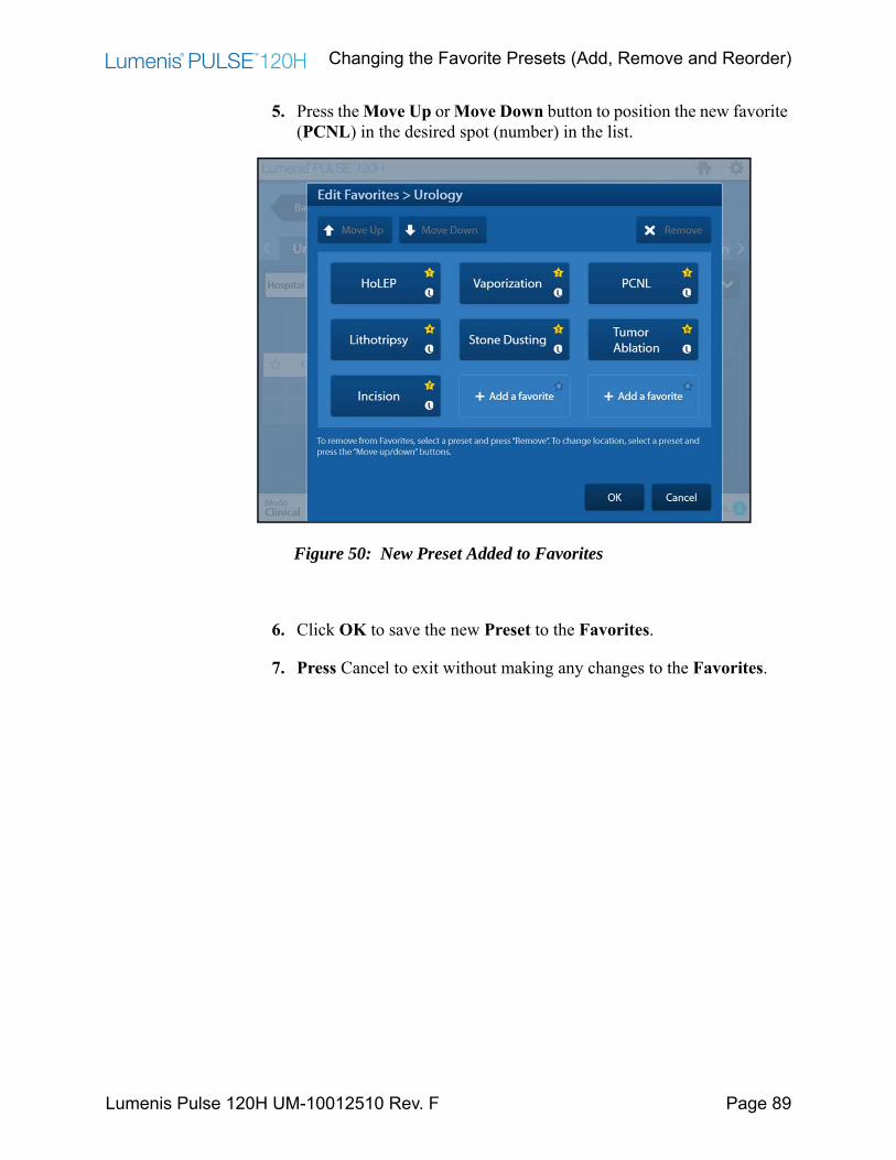
Changing the Favorite Presets (Add, Remove and Reorder)
Lumenis Pulse 120H UM-10012510 Rev. F Page 89
5. Press the Move Up or Move Down button to position the new favorite (PCNL) in the desired spot (number) in the list.
Figure 50: New Preset Added to Favorites
6. Click OK to save the new Preset to the Favorites.
7. Press Cancel to exit without making any changes to the Favorites.
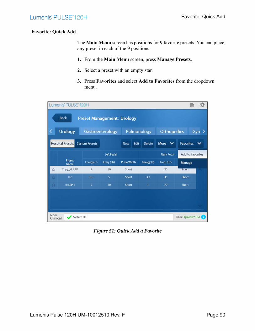
Favorite: Quick Add
Lumenis Pulse 120H UM-10012510 Rev. F Page 90
Favorite: Quick Add
The Main Menu screen has positions for 9 favorite presets. You can place any preset in each of the 9 positions.
1. From the Main Menu screen, press Manage Presets.
2. Select a preset with an empty star.
3. Press Favorites and select Add to Favorites from the dropdown menu.
Figure 51: Quick Add a Favorite
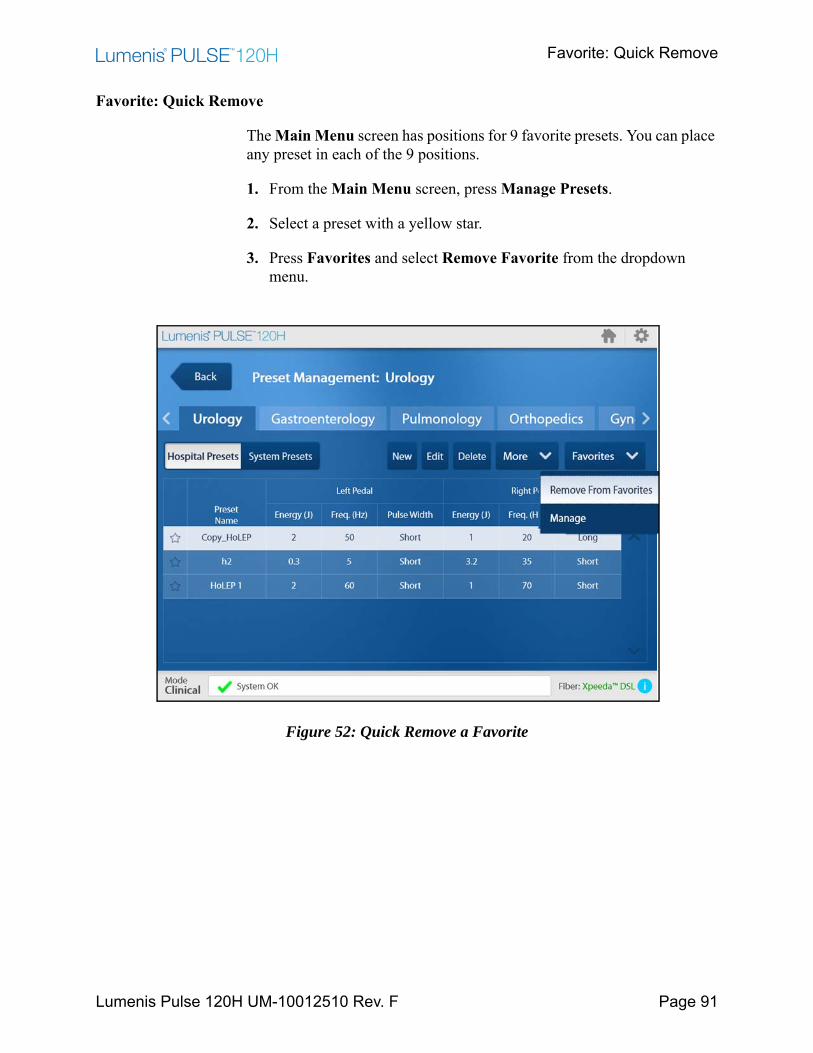
Favorite: Quick Remove
Lumenis Pulse 120H UM-10012510 Rev. F Page 91
Favorite: Quick Remove
The Main Menu screen has positions for 9 favorite presets. You can place any preset in each of the 9 positions.
1. From the Main Menu screen, press Manage Presets.
2. Select a preset with a yellow star.
3. Press Favorites and select Remove Favorite from the dropdown menu.
Figure 52: Quick Remove a Favorite

Reports
Lumenis Pulse 120H UM-10012510 Rev. F Page 92
Reports
Lumenis Pulse 120H automatically generates a report of each treatment.
1. To view a summary of the reports listed in chronological order with the most recent treatment on top, press the Reports button.
2. You can export the reports as log files, for more detailed analysis, to a USB storage device.
Figure 53: Reports Screen

Exporting the Reports
Lumenis Pulse 120H UM-10012510 Rev. F Page 93
Exporting the Reports
1. Insert a USB storage device into the USB port at the rear of the Lumenis Pulse 120H.
2. From the Home screen, press the Reports button.
3. Press the Export reports to USB button.
4. In the Export Reports confirmation screen, click OK.
Figure 54: Reports Export Confirmation Screen
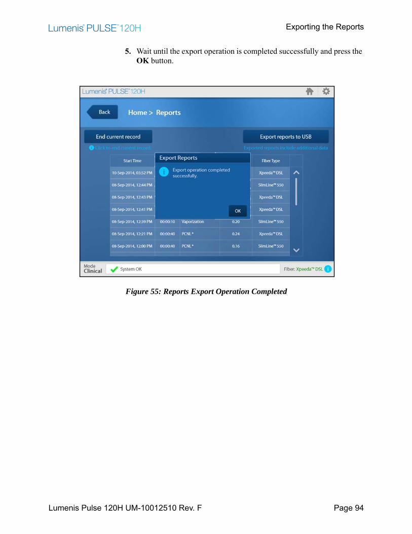
Exporting the Reports
Lumenis Pulse 120H UM-10012510 Rev. F Page 94
5. Wait until the export operation is completed successfully and press the OK button.
Figure 55: Reports Export Operation Completed

Changing the Default Specialty
Lumenis Pulse 120H UM-10012510 Rev. F Page 95
Changing the Default Specialty
When you start up Lumenis Pulse 120H, the Main Menu screen automatically displays the default specialty. You can change this in the Settings & Utilities screen.
1. From the Main Menu screen, press the Settings & Utilities button.
2. Press the Default Specialty button.
Figure 56: Default Specialty Button
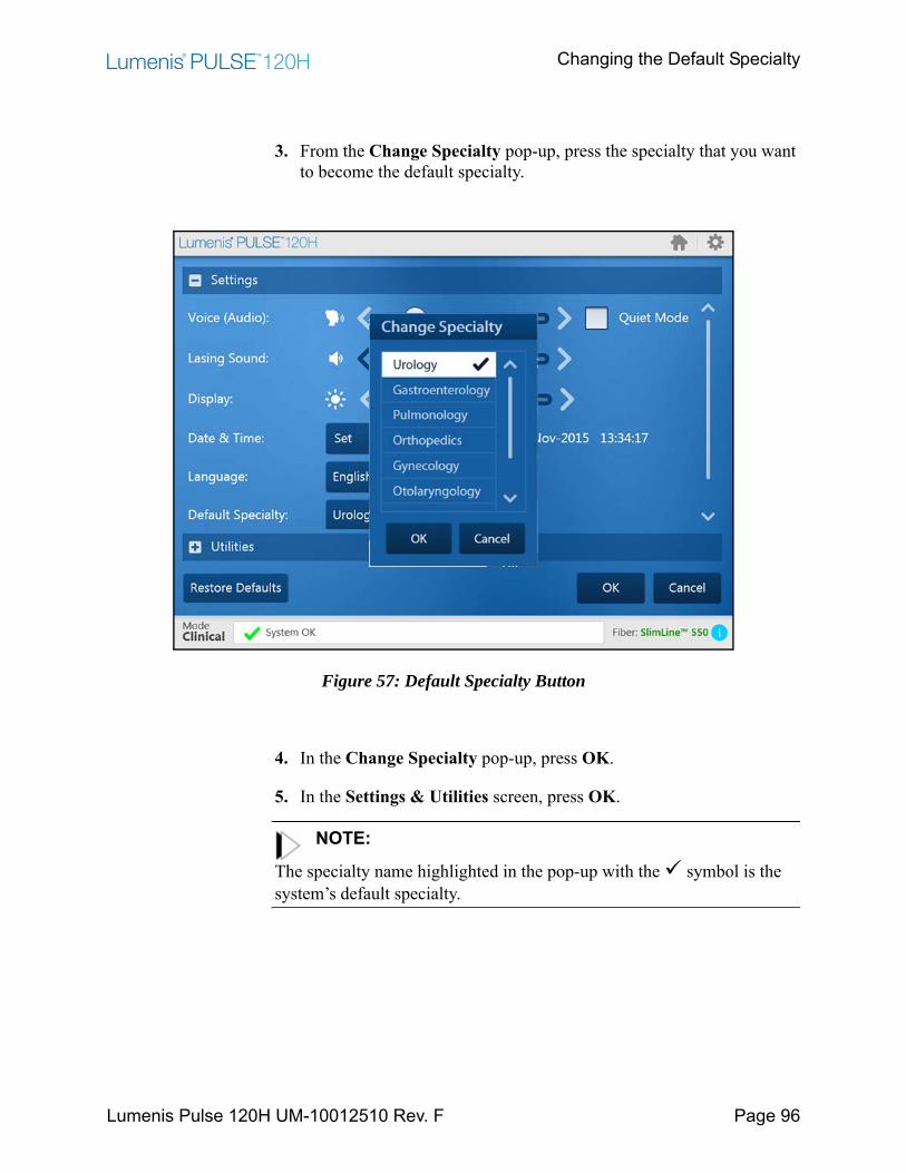
Changing the Default Specialty
Lumenis Pulse 120H UM-10012510 Rev. F Page 96
3. From the Change Specialty pop-up, press the specialty that you want to become the default specialty.
Figure 57: Default Specialty Button
4. In the Change Specialty pop-up, press OK.
5. In the Settings & Utilities screen, press OK.
NOTE:
The specialty name highlighted in the pop-up with the symbol is the system’s default specialty.
Other Operations
Lumenis Pulse 120H UM-10012510 Rev. F Page 97
Other Operations
Turning Off the Aiming Beam
Turn off the aiming beam by following the instructions on page 54 (Home Screen Description).
WARNING:Use extreme care if the aiming beam has been turned off. Operating the laser without the aiming beam may result in laser exposure to non-target tissue and possible injury.
CAUTION:• If the aiming beam has been turned off and you leave the treatment
screen, when you return to the Treatment screen the aiming beam will return to the default medium intensity.
• If the aiming beam has been turned off a pop-up message will appear requiring that you verify knowing that the aiming beam is turned off. Press the verification button in order to proceed with the surgical procedure.

Changing Screen Settings
Lumenis Pulse 120H UM-10012510 Rev. F Page 98
Changing Screen Settings
1. Press the cogwheel in the upper-right corner and select Quick Settings.
Figure 58: Select Quick Settings
2. In the Quick Settings screen that opens, slide the lower slider to the right to increase screen brightness or to the left to decrease screen brightness.
Figure 59: Quick Settings Pop-Up Screen
NOTE:Checking the Quiet Mode check box does not affect the signal that is emitted during lasing or any other sounds that are directly related to safety.
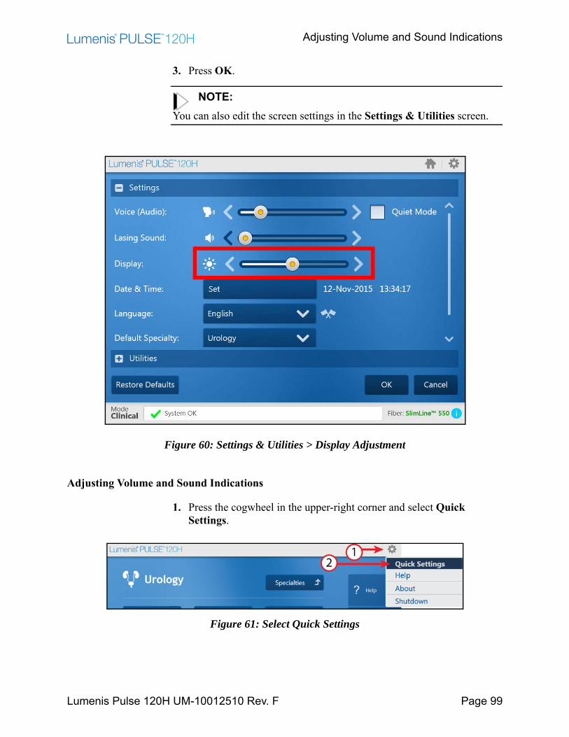
Adjusting Volume and Sound Indications
Lumenis Pulse 120H UM-10012510 Rev. F Page 99
3. Press OK.
NOTE:You can also edit the screen settings in the Settings & Utilities screen.
Figure 60: Settings & Utilities > Display Adjustment
Adjusting Volume and Sound Indications
1. Press the cogwheel in the upper-right corner and select Quick Settings.
Figure 61: Select Quick Settings
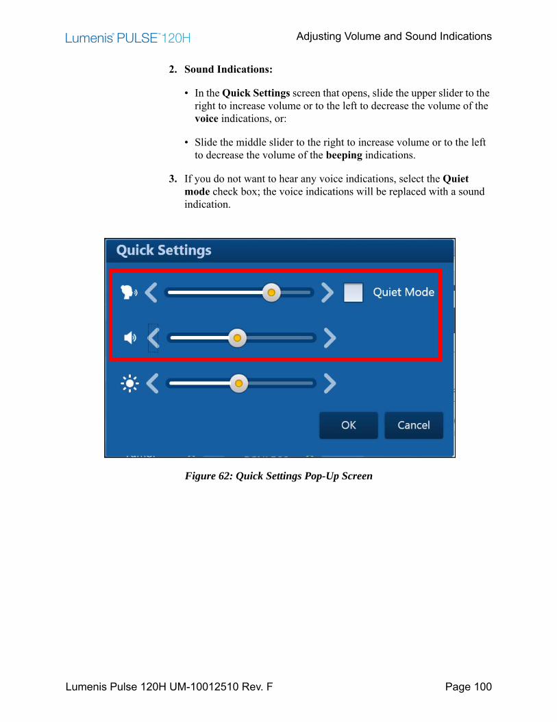
Adjusting Volume and Sound Indications
Lumenis Pulse 120H UM-10012510 Rev. F Page 100
2. Sound Indications:
• In the Quick Settings screen that opens, slide the upper slider to the right to increase volume or to the left to decrease the volume of the voice indications, or:
• Slide the middle slider to the right to increase volume or to the left to decrease the volume of the beeping indications.
3. If you do not want to hear any voice indications, select the Quiet mode check box; the voice indications will be replaced with a sound indication.
Figure 62: Quick Settings Pop-Up Screen

Adjusting Volume and Sound Indications
Lumenis Pulse 120H UM-10012510 Rev. F Page 101
4. Press OK.
NOTE:You can also edit the screen settings in the Settings & Utilities screen.
Figure 63: Settings & Utilities > Sound Indications Level Adjustments
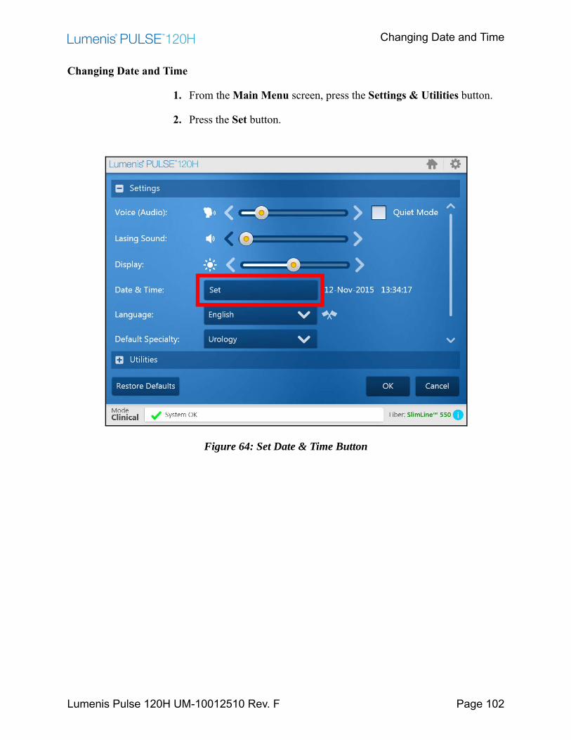
Changing Date and Time
Lumenis Pulse 120H UM-10012510 Rev. F Page 102
Changing Date and Time
1. From the Main Menu screen, press the Settings & Utilities button.
2. Press the Set button.
Figure 64: Set Date & Time Button
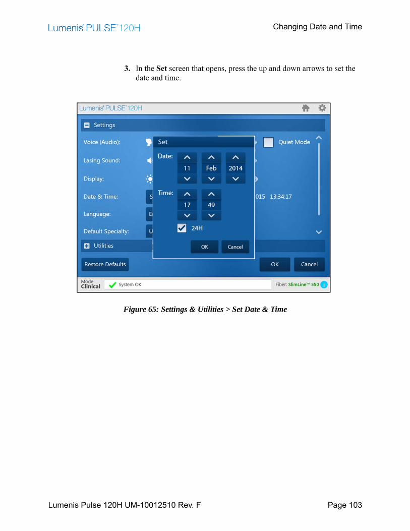
Changing Date and Time
Lumenis Pulse 120H UM-10012510 Rev. F Page 103
3. In the Set screen that opens, press the up and down arrows to set the date and time.
Figure 65: Settings & Utilities > Set Date & Time
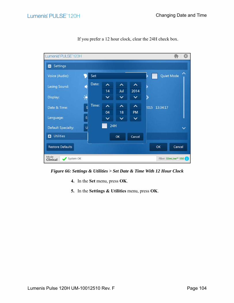
Changing Date and Time
Lumenis Pulse 120H UM-10012510 Rev. F Page 104
If you prefer a 12 hour clock, clear the 24H check box.
Figure 66: Settings & Utilities > Set Date & Time With 12 Hour Clock
4. In the Set menu, press OK.
5. In the Settings & Utilities menu, press OK.
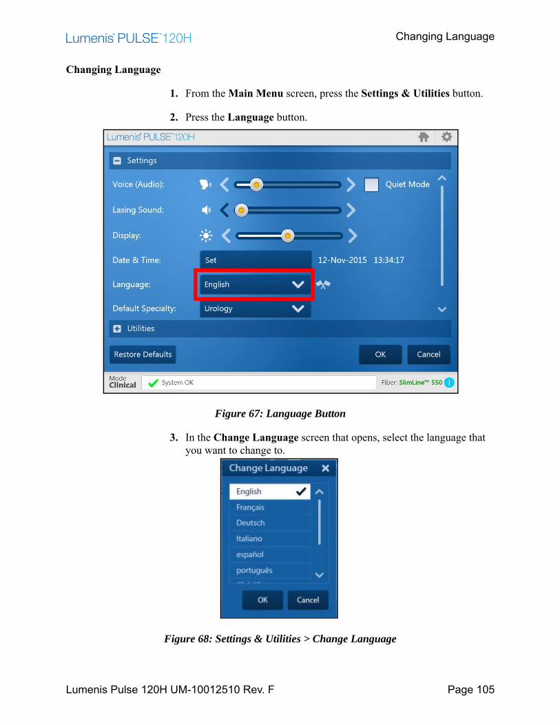
Changing Language
Lumenis Pulse 120H UM-10012510 Rev. F Page 105
Changing Language
1. From the Main Menu screen, press the Settings & Utilities button.
2. Press the Language button.
Figure 67: Language Button
3. In the Change Language screen that opens, select the language that you want to change to.
Figure 68: Settings & Utilities > Change Language
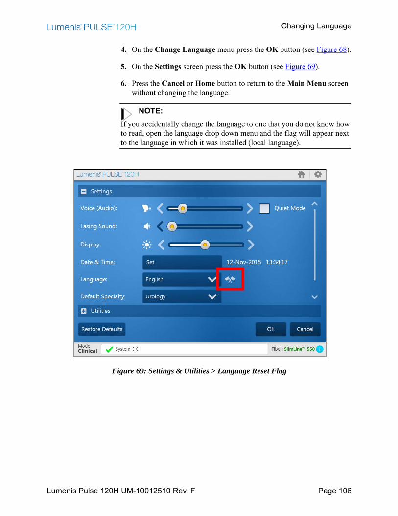
Changing Language
Lumenis Pulse 120H UM-10012510 Rev. F Page 106
4. On the Change Language menu press the OK button (see Figure 68).
5. On the Settings screen press the OK button (see Figure 69).
6. Press the Cancel or Home button to return to the Main Menu screen without changing the language.
NOTE:If you accidentally change the language to one that you do not know how to read, open the language drop down menu and the flag will appear next to the language in which it was installed (local language).
Figure 69: Settings & Utilities > Language Reset Flag
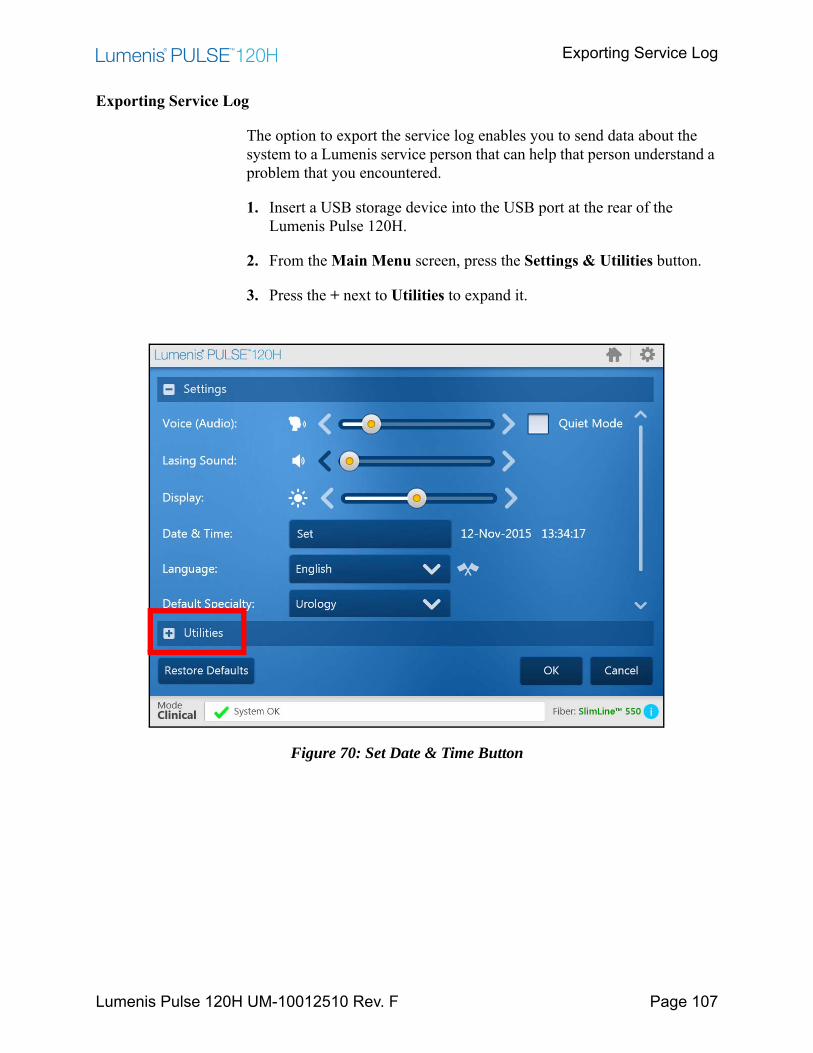
Exporting Service Log
Lumenis Pulse 120H UM-10012510 Rev. F Page 107
Exporting Service Log
The option to export the service log enables you to send data about the system to a Lumenis service person that can help that person understand a problem that you encountered.
1. Insert a USB storage device into the USB port at the rear of the Lumenis Pulse 120H.
2. From the Main Menu screen, press the Settings & Utilities button.
3. Press the + next to Utilities to expand it.
Figure 70: Set Date & Time Button

Exporting Service Log
Lumenis Pulse 120H UM-10012510 Rev. F Page 108
4. Insert a USB device.
5. Press the Export data to USB button.
Figure 71: Export Data to USB Button
6. In the Export data to USB pop-up menu press one of the following:• All• One Month• One Week• One Day
7. Press OK.
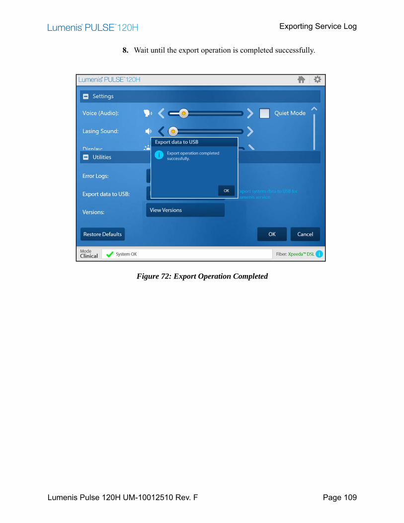
Exporting Service Log
Lumenis Pulse 120H UM-10012510 Rev. F Page 109
8. Wait until the export operation is completed successfully.
Figure 72: Export Operation Completed
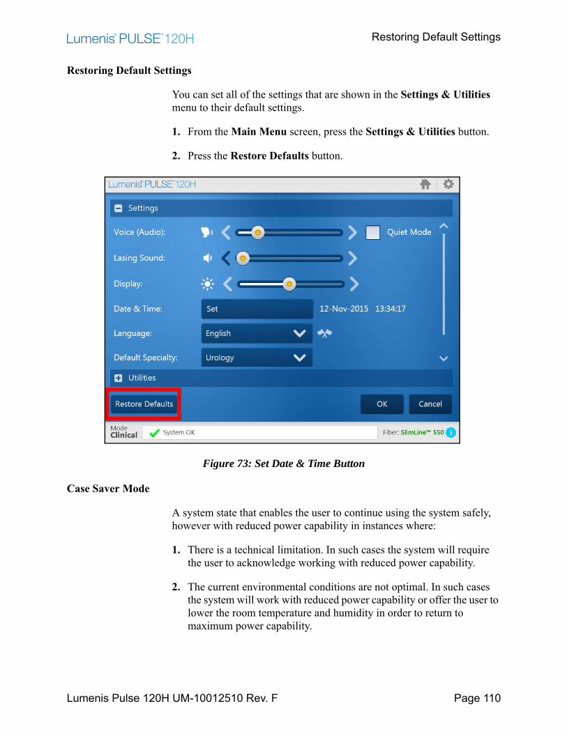
Restoring Default Settings
Lumenis Pulse 120H UM-10012510 Rev. F Page 110
Restoring Default Settings
You can set all of the settings that are shown in the Settings & Utilities menu to their default settings.
1. From the Main Menu screen, press the Settings & Utilities button.
2. Press the Restore Defaults button.
Figure 73: Set Date & Time Button
Case Saver Mode
A system state that enables the user to continue using the system safely, however with reduced power capability in instances where:
1. There is a technical limitation. In such cases the system will require the user to acknowledge working with reduced power capability.
2. The current environmental conditions are not optimal. In such cases the system will work with reduced power capability or offer the user to lower the room temperature and humidity in order to return to maximum power capability.
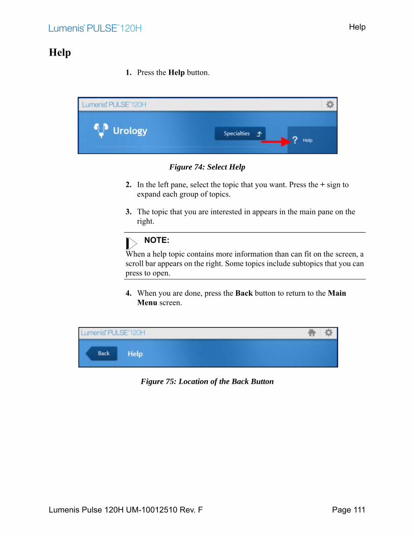
Help
Lumenis Pulse 120H UM-10012510 Rev. F Page 111
Help
1. Press the Help button.
Figure 74: Select Help
2. In the left pane, select the topic that you want. Press the + sign to expand each group of topics.
3. The topic that you are interested in appears in the main pane on the right.
NOTE:When a help topic contains more information than can fit on the screen, a scroll bar appears on the right. Some topics include subtopics that you can press to open.
4. When you are done, press the Back button to return to the Main Menu screen.
Figure 75: Location of the Back Button
Troubleshooting and Maintenance
Lumenis Pulse 120H UM-10012510 Rev. F Page 112
Troubleshooting and MaintenanceHandling Error Messages and Notifications
Notifications and error messages appear in the Notification bar at the bottom of the screen. If you press READY while there is an error, it opens the Notification screen. You can also open it from the notification bar as a pop-up by pressing the Show Notifications button. Refer to Figure 76.1. Follow the instructions for the error message or notification.2. For notifications, press the Acknowledge all button.
• A check mark will appear to show that you have acknowledged the message and the notification will fade.
• If the notification is ignored, it will remain in the list.• If it is an error message, depending on the severity of the error, the
system may require a restart or to be shut down and not operated until serviced professionally.
3. For errors, perform the required task as detailed in the error message. If the error is fixed, the message will fade and no longer appear in the notification bar.If the error is not corrected by a user action, the error will not fade and you will be prevented from lasing.
4. Repeat for each error message and notification.
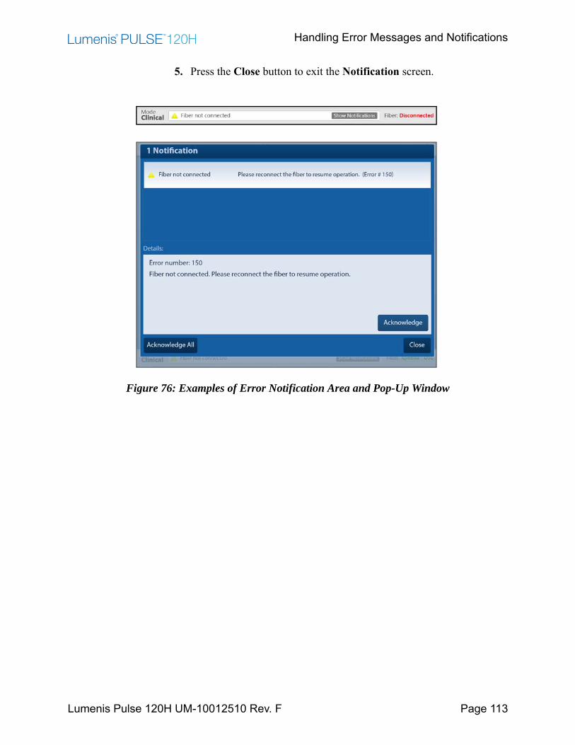
Handling Error Messages and Notifications
Lumenis Pulse 120H UM-10012510 Rev. F Page 113
5. Press the Close button to exit the Notification screen.
Figure 76: Examples of Error Notification Area and Pop-Up Window
Troubleshooting
Lumenis Pulse 120H UM-10012510 Rev. F Page 114
Troubleshooting
If the instrument fails to operate properly, this troubleshooting guide will help you to locate and correct the malfunction.
Initialization Problem Screen Pops Up
1. Write down the error number.
2. Press the Shutdown button.
3. If the problem re-occurs, contact Lumenis service.
4. Turn on the system with the keyswitch in the Off position.
5. Export logs and send them to Lumenis service.
System Does Not Turn On
The control screen does not illuminate. No blue light in the On/Off switch and around the delivery system port.
1. Plug in the laser.
2. Set the laser's main circuit breaker to the On (up) position.
3. Turn on the main electrical service power.
4. Use another outlet, or have the outlet professionally tested and repaired, if necessary.
Inadequate or No Aiming Beam
1. Adjust the aiming beam intensity.
2. Replace the delivery system.
3. Lower the intensity of the endoscopic camera light.
4. Inspect and, if necessary, replace the debris shield.
5. Contact your local Lumenis service representative.
No Laser Emission
Lumenis Pulse 120H UM-10012510 Rev. F Page 115
No Laser Emission
1. Replace the delivery system.
2. Inspect and, if necessary, replace the debris shield.
3. Contact your local Lumenis service representative.
A Notification Appears on the Control Screen
1. Clear the message by pressing the Acknowledge button and follow the suggested steps intended to clear the fault.
2. Resume normal operation; if the same notification appears again, turn off the laser system for one minute and restart it. Resume normal operation.
3. If the same notification appears again, record the error number and contact your local Lumenis service representative.
Cooling System Notification
The following notification appears on the control screen: System overheated.
1. Press the Show Notifications icon to open a pop-up window that displays the nature of the notification.
2. Clear the message by pressing the Acknowledge button and pause operation for one minute to allow the system to cool.
3. Resume normal operation; if the same notification appears again, turn off the laser system for five minutes and restart it. Resume normal operation.
4. If the same notification appears again, record the error number and contact your local Lumenis service representative.
Fiber Exceeded Recommend # of Uses. It is Advised to Replace the Fiber
1. Be aware that the fiber has exceeded the recommended number of uses.
2. Replace the optical fiber with a new one.

“Popping” or “Tapping” Coming Sound from the Fiber Port
Lumenis Pulse 120H UM-10012510 Rev. F Page 116
“Popping” or “Tapping” Coming Sound from the Fiber Port
This is probably due to a malfunction of the fiber connector.
1. Replace both the fiber and the debris shield.
Fiber Burn Back
Fiber burn back may occur during prolonged procedures, especially when using higher power.
1. Renew the fiber tip by stripping and cleaving the fiber.
Power Limited
A limitation may be the result of a specific fiber that is used.
1. Choose appropriate fiber type for increased power.
Fiber Expired
1. Replace the fiber with a new one and resume normal operation.
2. If problem persists, contact Lumenis Service.
Unrecognized Fiber
1. Replace the fiber with a Lumenis compatible one and resume normal operation.
2. If problem persists, contact Lumenis Service.
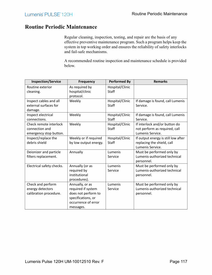
Routine Periodic Maintenance
Lumenis Pulse 120H UM-10012510 Rev. F Page 117
Routine Periodic Maintenance
Regular cleaning, inspection, testing, and repair are the basis of any effective preventive maintenance program. Such a program helps keep the system in top working order and ensures the reliability of safety interlocks and fail-safe mechanisms.
A recommended routine inspection and maintenance schedule is provided below.
Inspection/Service Frequency Performed By RemarksRoutine exterior cleaning.
As required by hospital/clinic protocol.
Hospital/Clinic Staff
Inspect cables and all external surfaces for damage.
Weekly Hospital/Clinic Staff
If damage is found, call Lumenis Service.
Inspect electrical connections.
Weekly Hospital/Clinic Staff
If damage is found, call Lumenis Service.
Check remote interlock connection and emergency stop button.
Weekly Hospital/Clinic Staff
If interlock and/or button do not perform as required, call Lumenis Service.
Inspect/replace the debris shield
Weekly or if required by low output energy.
Hospital/Clinic Staff
If output energy is still low after replacing the shield, call Lumenis Service.
Deionizer and particle filters replacement.
Annually Lumenis Service
Must be performed only by Lumenis-authorized technical personnel.
Electrical safety checks. Annually (or as required by institutional procedures).
Lumenis Service
Must be performed only by Lumenis-authorized technical personnel.
Check and perform energy detectors calibration procedure.
Annually, or as required if system does not perform to specifications, or occurrence of error messages.
Lumenis Service
Must be performed only by Lumenis-authorized technical personnel.

Hospital/Clinic Staff Maintenance
Lumenis Pulse 120H UM-10012510 Rev. F Page 118
Hospital/Clinic Staff Maintenance
Visual Inspection
The exterior of the system should be inspected once a week to ensure that there are no loose cable connections and that there is no damage to the system.
Routine Exterior Cleaning
The external surfaces of the system (console, LCD panel) and the footswitch should be cleaned when the system is received, and thereafter as required by clinic protocol.
The outer surfaces of the system may be wiped clean with a soft, lint-free cloth dipped in 70% isopropyl alcohol, or a hospital-grade disinfectant solution.
CAUTION:Do not spray or pour cleaning agents directly on the laser console or control screen. You may damage the console, screen, and laser system electronics.
Remote Interlock Check
Laser beam emission is disabled when the remote interlock plug is not connected or is improperly connected to the rear panel, even if it is not wired to an actual door interlock. To check this:
1. Set the system to Standby mode.
2. Unplug the remote interlock plug.
3. Try to select Ready mode. The system should display the following warning message in the notification bar: Verify door closed.
4. If the system does not display the warning message and remains in Ready mode, discontinue use and contact Lumenis Service.
Emergency Stop Button Check
Lumenis Pulse 120H UM-10012510 Rev. F Page 119
Emergency Stop Button Check
The Emergency Stop Button is designed to disable the laser when pressed. To check this interlock:
1. With the system On, press down on the emergency stop button; the system’s internal components will be powered down and laser emission will be disabled. This should be verified by trying to access Ready mode and noting that Ready mode is not available.
2. Turn the button clockwise to release it and restart the system.
3. Press the Ready button on the LCD to enable lasing.
If this is not the situation, discontinue use and contact Lumenis Service.
Inspect / Replace the Debris Shield
If you hear an abnormal popping sound while delivering the treatment beam, accompanied by a dramatic reduction in treatment effect, the debris shield and/or the optical fiber have probably failed; you should immediately stop treatment and inspect both the debris shield and the fiber.
NOTE:Refer to the delivery system's instruction guide for fiber inspection instructions.
The debris shield is a replaceable part that protects the laser system's optical components from damage by a failed delivery system. The debris shield is like a fuse: you only need to replace it if inspection reveals that it is damaged.
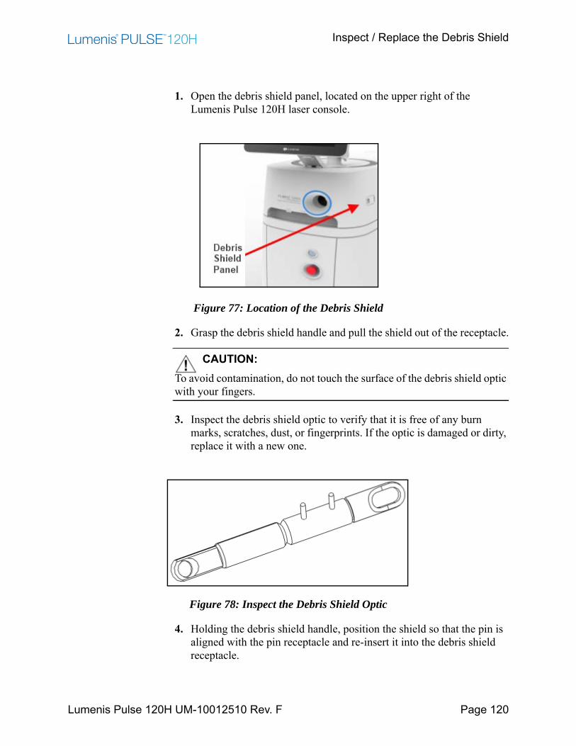
Inspect / Replace the Debris Shield
Lumenis Pulse 120H UM-10012510 Rev. F Page 120
1. Open the debris shield panel, located on the upper right of the Lumenis Pulse 120H laser console.
Figure 77: Location of the Debris Shield
2. Grasp the debris shield handle and pull the shield out of the receptacle.
CAUTION:To avoid contamination, do not touch the surface of the debris shield optic with your fingers.
3. Inspect the debris shield optic to verify that it is free of any burn marks, scratches, dust, or fingerprints. If the optic is damaged or dirty, replace it with a new one.
Figure 78: Inspect the Debris Shield Optic
4. Holding the debris shield handle, position the shield so that the pin is aligned with the pin receptacle and re-insert it into the debris shield receptacle.
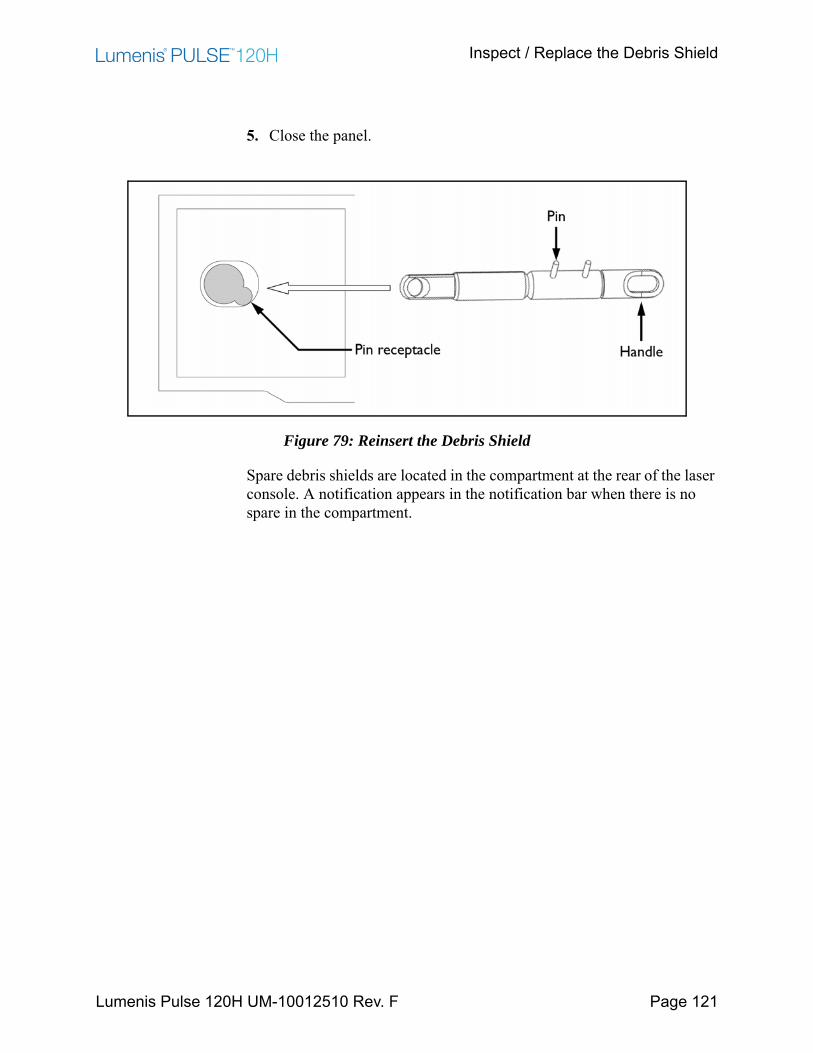
Inspect / Replace the Debris Shield
Lumenis Pulse 120H UM-10012510 Rev. F Page 121
5. Close the panel.
Figure 79: Reinsert the Debris Shield
Spare debris shields are located in the compartment at the rear of the laser console. A notification appears in the notification bar when there is no spare in the compartment.
Professional Maintenance
Lumenis Pulse 120H UM-10012510 Rev. F Page 122
Professional Maintenance
This section covers checks, calibrations and maintenance that require internal access to the Lumenis Pulse 120H console and special skills.
CAUTION:The Lumenis Pulse 120H laser system shall be serviced by Lumenis certified field service engineer using an approved service manual.
WARNING:These procedures assume specific knowledge, training and use of tools not available to repair personnel outside of Lumenis. Since performing these procedures may expose the user to potential electrical and laser energy hazards, Lumenis requires that these procedures only be performed by trained service personnel.
Energy Detectors Calibration
Energy detectors check and calibration must be performed by an engineer or technician qualified to work with laser equipment. Questions regarding this procedure should be referred to your local Lumenis representative.
DISCLAIMER:Calibration is a service procedure to be done only by Lumenis-certified service engineers or customers who have taken and passed a Lumenis Service Certification Training course. Adjustment by anyone other than a trained Lumenis service engineer or a certified customer voids any existing manufacturer’s warranty on the instrument. A service manual for the laser may be purchased from Lumenis. It is company policy not to distribute service tools outside of the Lumenis service organization. Possession of service instructions or tools does not authorize repair or modification of a Lumenis instrument by uncertified personnel.

Energy Detectors Calibration
Lumenis Pulse 120H UM-10012510 Rev. F Page 123
The Lumenis Pulse 120H system incorporates internal energy detectors which are used to control lasing energy. The energy detectors check compares the internal energy reading to the reading from an external power meter.
WARNING:All personnel in the immediate area must wear eye protection rated spe-cifically for the Holmium laser.
NOTE:Optical components must be clean before the energy detectors check is performed.
1. Verify that all personnel are wearing the appropriate laser safety eyewear.
2. Position a calibrated, external power meter 15 cm (6 inches) from the output end of the optical fiber.
3. Turn on the laser as instructed in the Normal Operation chapter of this manual.
4. Set the laser system to deliver 5 Watts of laser energy.
5. Target the aiming beam at the detector disc of the external power meter.
6. Set the laser system to READY mode.
7. Press the footswitch to deliver the laser energy into the detector disc of the external power meter. Maintain delivery of the laser energy for 20 seconds.
8. Release the footswitch and record the external power meter's reading.
9. If the external power meter reading falls above or below 20% of the requested energy on your laser, discontinue this procedure and contact your local Lumenis service representative.
System Requirements and General Information
Lumenis Pulse 120H UM-10012510 Rev. F Page 124
System Requirements and General InformationInstallation
The laser is shipped directly from the factory to your site. Your local Lumenis service representative initially uncrates, inspects, sets up, and installs the laser to ensure that it is working properly. In addition, Lumenis provides in-service training to ensure that your surgical staff is experienced with the performance and safety considerations of the laser.
Thereafter, you or the nursing staff at your facility will perform the daily maintenance routines associated with the laser and any delivery systems used during surgery.
If your scheduled surgical procedure requires disposable delivery devices or accessories, it is helpful to have extra items ready and available in the treatment room should they be needed to complete a procedure.
CAUTION:For Canada, the system must be installed and operated according to CAN/CSA-Z386-08: Laser safety in health care facilities.
Accessories
Lumenis Pulse 120H UM-10012510 Rev. F Page 125
Accessories
Delivery Devices and Accessories
• SlimLine / aa SlimLine SIS 200, 365, 550, 1000• SlimLine EZ / SlimLine EZ SIS 200, 365, 550• SlimLine GI SIS 365• Duotome• Xpeeda D/S/L• Slimline 200 D/F/L• Moses D/F/L 200, 365, 550• Sterile aspiration tubing• Non-sterile drainage tubing• Collection container• Suction handpiece
Additional Accessories
• Fiber cutting scissors• Optical fiber strippers• Cleaving tool• SlimLine steam sterilization tray• Safety eyewear
Electrical Requirements
Electrical Utilities
The Lumenis Pulse 120H holmium laser is available in two electrical configurations:
• Single-phase (200-240 VAC, <46A, 50 or 60 Hz)• Three-phase (380-415 VAC, <18A per phase, 50 Hz)
Electrical power should be setup according to the model ordered. The service technician will configure the system during installation for the site voltage and verify that the installed power plug is compatible with the receptacle provided by the hospital.
Removable or Lockable Wall Socket and Plug Configurations
Lumenis Pulse 120H UM-10012510 Rev. F Page 126
Removable or Lockable Wall Socket and Plug Configurations
If the laser is installed with a removable plug or wall socket and lockable plug combination prior to installation, the customer’s engineer or electrical contractor will be responsible for ensuring that the proper electrical requirements are available at the site.
When installed with a removable or lockable wall plug, the socket and wall plug connection must be rated for higher than the electrical requirements of the specific configuration. In most instances, customers must purchase a suitable electrical connection kit locally.
Compliance With International Standards
In accordance with regulations a recommended routine inspection and maintenance schedule is provided in the System Requirements and General Information section of this manual.
In compliance with these standards, the system is equipped with the following:
Emergency Stop Button
The laser has an emergency stop button knob that, when pushed, immediately disables the laser in emergency situations.
Keyswitch
Laser energy can be emitted only when the keyswitch is turned to the Open position. The key can only be removed in the off position, and the laser only operates with the key in place. When treatment is complete, always remove and secure the key to prevent unauthorized use of the laser.
WARNING:Unauthorized use of this system may expose the operator/patient to poten-tial electrical energy and laser radiation hazards.
Laser Emission Indicators
Lumenis Pulse 120H UM-10012510 Rev. F Page 127
Laser Emission Indicators
A laser emission icon appears on the control screen to alert you that laser energy is being emitted. During the treatment beam delivery, the laser emits an auditory signal correlating to the pedal used.
The system also verbalizes "READY" and "STANDBY" with a voice indicator when the system is transitioned from mode to mode.
External Door Interlock
An external door interlock outlet and plug are provided to disable the laser if the treatment room doors are opened while the laser is in READY mode.
Protective Housing
The laser has a protective housing that prevents unintended human access to laser radiation. No sections of the protective housing can be easily opened without special tools. This housing is to be opened only by a Lumenis-certified technician.
Safety Shutter
The laser features a safety shutter that prevents the treatment beam from exiting the laser. The safety shutter opens only when the laser is in ready mode and the footswitch is pressed.
Manual Reset
If laser emission is interrupted during treatment (e.g., main electrical power loss), the laser automatically turns Off. To resume treatment, you must manually restart the laser using the main On/Off button.
Electronic Fault Detection Circuitry
If any of the electronic system monitors detect a fault condition, laser exposure cannot occur. The high voltage power supply disables, the safety shutter closes, and the footswitch disables.
Safety Interlocks
The laser has a safety interlock on the fiber optic laser connector.

Precision of Displayed Values
Lumenis Pulse 120H UM-10012510 Rev. F Page 128
Precision of Displayed Values
The precision of the energy and rate values displayed on the control screen are factory preset to within ±5% of a calibrated standard. The energy of every pulse is monitored by two internal detectors to ensure that no safety hazard is caused by failure of a single component. If the delivered system energy deviates from the commanded parameters by more than 20%, you are notified and can continue lasing following acknowledgment. Following 5 such occurrences in a single session this becomes a fatal error and lasing cannot continue (laser shuts down).
Space Requirements
Position the laser console a minimum of 50 centimeters (20 inches) from walls, furniture, or other equipment.
Specifications
Specifications are subject to change without notice.
Treatment Beam
NOTE:When using a 32A configuration the average maximum power will be limited in order to meet the maximum current limits.
Laser Medium/Energy Source Holmium:YAG crystal rod
Wavelength 2.1 µm
Laser Mode Pulsed
Maximum Average Power 120 W
Pulse Energy 0.2 – 6 J
Pulse Frequency 5 - 80 Hz
Max Pulse Duration 1300 µs
US FDA CDRH laser classification: Class IV
European EN 60825 laser classification: Class 4
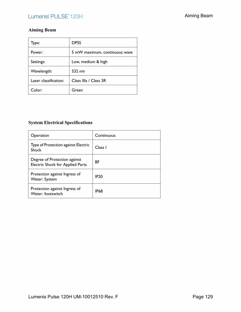
Aiming Beam
Lumenis Pulse 120H UM-10012510 Rev. F Page 129
Aiming Beam
System Electrical Specifications
Type: DPSS
Power: 5 mW maximum, continuous wave
Settings: Low, medium & high
Wavelength: 532 nm
Laser classification: Class IIIa / Class 3R
Color: Green
Operation Continuous
Type of Protection against Electric Shock
Class I
Degree of Protection against Electric Shock for Applied Parts
BF
Protection against Ingress of Water: System
IP20
Protection against Ingress of Water: footswitch
IP68
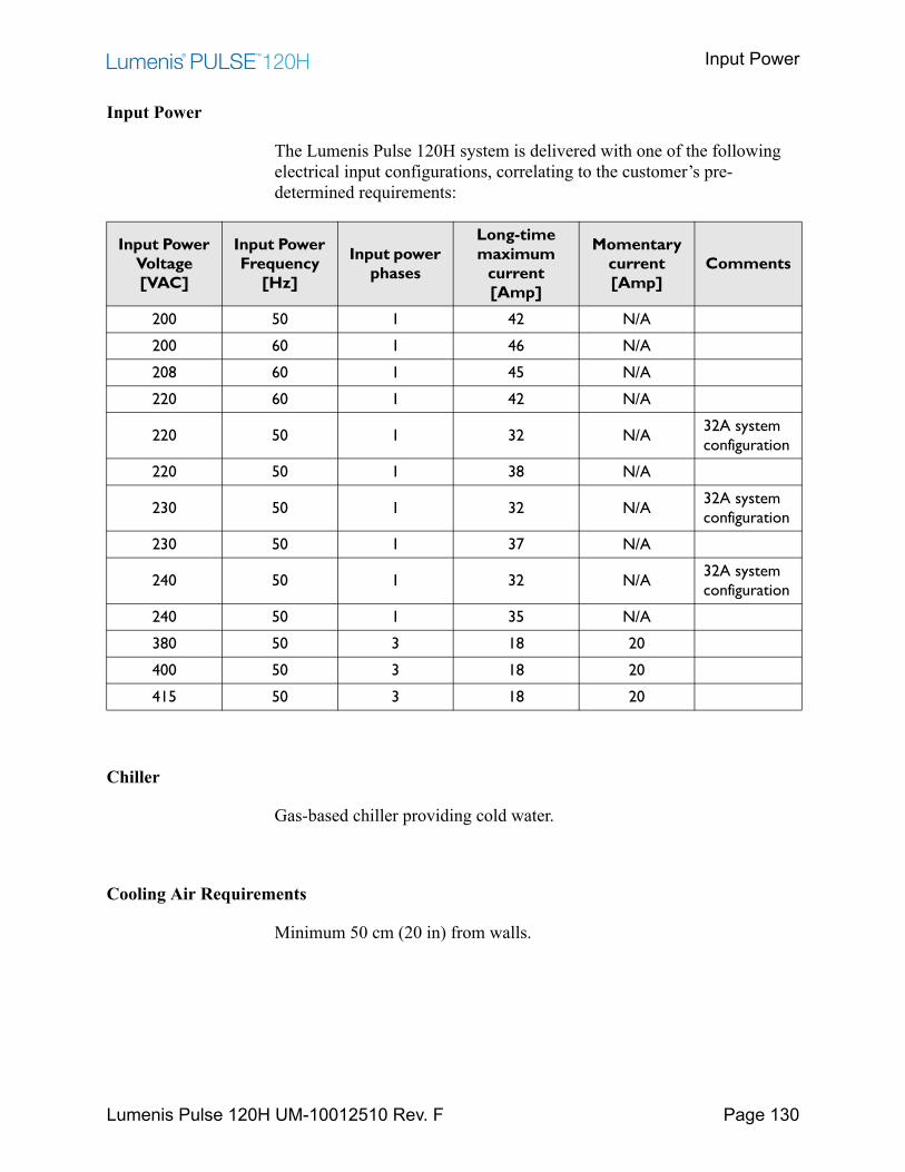
Input Power
Lumenis Pulse 120H UM-10012510 Rev. F Page 130
Input Power
The Lumenis Pulse 120H system is delivered with one of the following electrical input configurations, correlating to the customer’s pre-determined requirements:
Chiller
Gas-based chiller providing cold water.
Cooling Air Requirements
Minimum 50 cm (20 in) from walls.
Input Power Voltage [VAC]
Input Power Frequency
[Hz]
Input power phases
Long-time maximum
current [Amp]
Momentary current [Amp]
Comments
200 50 1 42 N/A
200 60 1 46 N/A
208 60 1 45 N/A
220 60 1 42 N/A
220 50 1 32 N/A32A system configuration
220 50 1 38 N/A
230 50 1 32 N/A32A system configuration
230 50 1 37 N/A
240 50 1 32 N/A32A system configuration
240 50 1 35 N/A
380 50 3 18 20
400 50 3 18 20
415 50 3 18 20
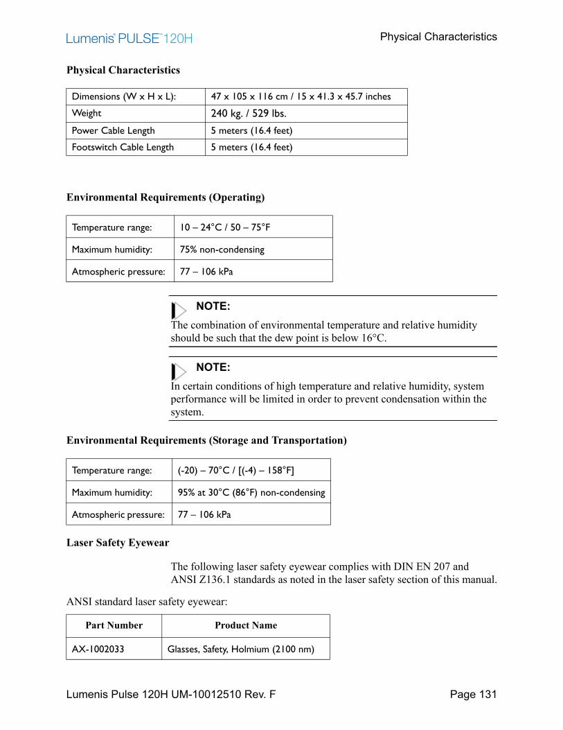
Physical Characteristics
Lumenis Pulse 120H UM-10012510 Rev. F Page 131
Physical Characteristics
Environmental Requirements (Operating)
NOTE:The combination of environmental temperature and relative humidity should be such that the dew point is below 16°C.
NOTE:In certain conditions of high temperature and relative humidity, system performance will be limited in order to prevent condensation within the system.
Environmental Requirements (Storage and Transportation)
Laser Safety Eyewear
The following laser safety eyewear complies with DIN EN 207 and ANSI Z136.1 standards as noted in the laser safety section of this manual.
Dimensions (W x H x L): 47 x 105 x 116 cm / 15 x 41.3 x 45.7 inches
Weight 240 kg. / 529 lbs.
Power Cable Length 5 meters (16.4 feet)
Footswitch Cable Length 5 meters (16.4 feet)
Temperature range: 10 – 24°C / 50 – 75°F
Maximum humidity: 75% non-condensing
Atmospheric pressure: 77 – 106 kPa
Temperature range: (-20) – 70°C / [(-4) – 158°F]
Maximum humidity: 95% at 30°C (86°F) non-condensing
Atmospheric pressure: 77 – 106 kPa
ANSI standard laser safety eyewear:
Part Number Product Name
AX-1002033 Glasses, Safety, Holmium (2100 nm)
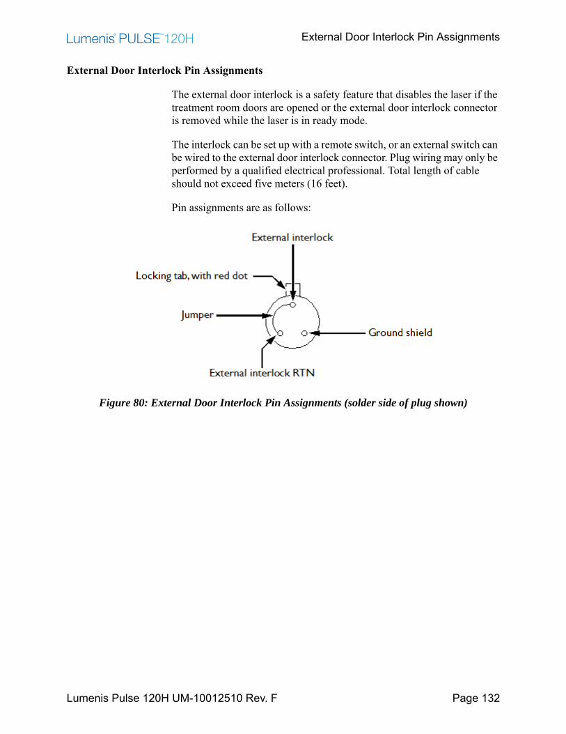
External Door Interlock Pin Assignments
Lumenis Pulse 120H UM-10012510 Rev. F Page 132
External Door Interlock Pin Assignments
The external door interlock is a safety feature that disables the laser if the treatment room doors are opened or the external door interlock connector is removed while the laser is in ready mode.
The interlock can be set up with a remote switch, or an external switch can be wired to the external door interlock connector. Plug wiring may only be performed by a qualified electrical professional. Total length of cable should not exceed five meters (16 feet).
Pin assignments are as follows:
Figure 80: External Door Interlock Pin Assignments (solder side of plug shown)
Customer Service
Lumenis Pulse 120H UM-10012510 Rev. F Page 133
Customer ServiceWarranty
Lumenis warrants the Lumenis Pulse 120H system and its accessories to be free from defects in materials and workmanship, and to perform in the manner and under the conditions specified in the operator’s manual. A defective device must be returned to Lumenis or an authorized Lumenis representative. Refer to the next section for information about returning equipment to Lumenis. For specific and detailed warranty information for this instrument, refer to the first page of your purchase “Agreement” and the last page of the “Terms and Conditions of Sale”.
Returning Equipment
Before sending equipment to Lumenis, call your local Lumenis representative or the closest Customer Service Center (http://www.Lumenis.com/contact1) to obtain a Return Material Authorization (RMA) tracking number.
To comply with postal and transportation laws, used equipment shipped to Lumenis or authorized representatives for return or repair must be properly decontaminated according to the cleaning and sterilization instructions. To document that all equipment has been properly decontaminated, a signed Certificate of Decontamination must be enclosed in the package. Failure to enclose the certificate will cause the supplier to assume that the product is contaminated and will assess the customer with cleaning costs. Any decontamination inquiries should be directed to your closest Lumenis Service Center.
Customer Feedback
Contact the closest Customer Service Center (http://www.Lumenis.com/contact1) with any feedback or to report any adverse events.

Appendix A: EMC Compliance
Lumenis Pulse 120H UM-10012510 Rev. F Page 134
Appendix A: EMC ComplianceElectromagnetic Emissions
Guidance and manufacturer’s declaration – electromagnetic emissions The Lumenis Pulse 120H is intended for use in the electromagnetic environment specified below. The customer or the user of the Lumenis Pulse 120H should assure that it is used in such an environment.
Emissions test Compliance Electromagnetic environment – guidance RF emissions CISPR 11 Group 1 The Lumenis Pulse 120H uses RF energy only for its
internal function. Therefore, its RF emissions are very low and are not likely to cause any interference in nearby electronic equipment.
RF emissionsCISPR 11
Class A The Lumenis Pulse 120H is suitable for use in all establishments other than domestic and those directly connected to the public low-voltage power supply network that supplies buildings used for domestic purposes.
Harmonic emissions IEC 61000-3-2
Not applicable The system consumes more than 16A momentary current per phase, and therefore is exempt from these requirements.
Voltage fluctuations/ flicker emissions IEC 61000-3-3
Not applicable The system consumes more than 16A momentary current per phase, and therefore is exempt from these requirements.
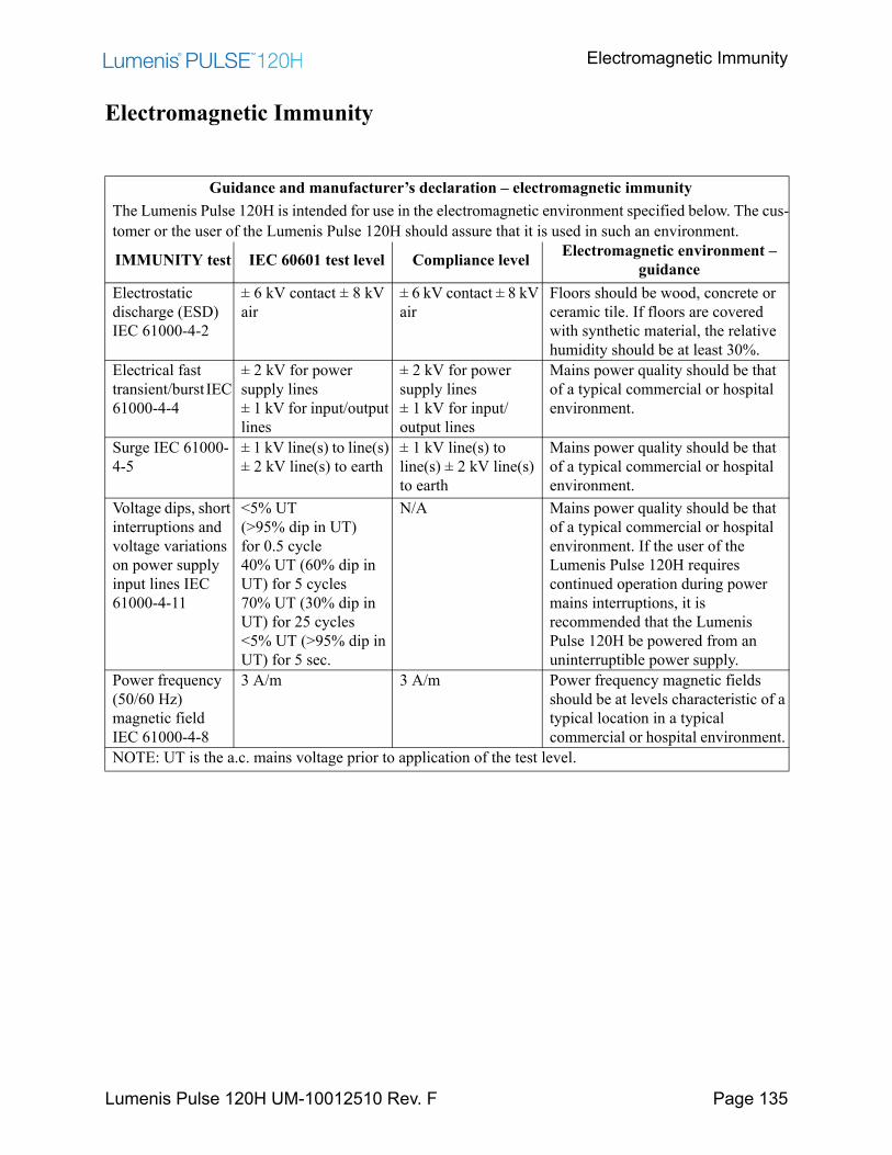
Electromagnetic Immunity
Lumenis Pulse 120H UM-10012510 Rev. F Page 135
Electromagnetic Immunity
Guidance and manufacturer’s declaration – electromagnetic immunity The Lumenis Pulse 120H is intended for use in the electromagnetic environment specified below. The cus-tomer or the user of the Lumenis Pulse 120H should assure that it is used in such an environment.
IMMUNITY test IEC 60601 test level Compliance level Electromagnetic environment – guidance
Electrostatic discharge (ESD) IEC 61000-4-2
± 6 kV contact ± 8 kV air
± 6 kV contact ± 8 kV air
Floors should be wood, concrete or ceramic tile. If floors are covered with synthetic material, the relative humidity should be at least 30%.
Electrical fast transient/burst IEC 61000-4-4
± 2 kV for power supply lines ± 1 kV for input/output lines
± 2 kV for power supply lines ± 1 kV for input/output lines
Mains power quality should be that of a typical commercial or hospital environment.
Surge IEC 61000-4-5
± 1 kV line(s) to line(s) ± 2 kV line(s) to earth
± 1 kV line(s) to line(s) ± 2 kV line(s) to earth
Mains power quality should be that of a typical commercial or hospital environment.
Voltage dips, short interruptions and voltage variations on power supply input lines IEC 61000-4-11
<5% UT(>95% dip in UT) for 0.5 cycle40% UT (60% dip in UT) for 5 cycles70% UT (30% dip in UT) for 25 cycles <5% UT (>95% dip in UT) for 5 sec.
N/A Mains power quality should be that of a typical commercial or hospital environment. If the user of the Lumenis Pulse 120H requires continued operation during power mains interruptions, it is recommended that the Lumenis Pulse 120H be powered from an uninterruptible power supply.
Power frequency (50/60 Hz) magnetic field IEC 61000-4-8
3 A/m 3 A/m Power frequency magnetic fields should be at levels characteristic of a typical location in a typical commercial or hospital environment.
NOTE: UT is the a.c. mains voltage prior to application of the test level.

Electromagnetic Immunity
Lumenis Pulse 120H UM-10012510 Rev. F Page 136
Guidance and manufacturer’s declaration – electromagnetic immunity The Lumenis Pulse 120H is intended for use in the electromagnetic environment specified below. The customer or the user of the Lumenis Pulse 120H should assure that it is used in such an environment.
IMMUNITY test
IEC 60601 TEST LEVEL
Compliance level Electromagnetic environment – guidance
Conducted RF IEC 61000-4-6
Radiated RF IEC 61000-4-3
3 Vrms 150 kHz to 80 MHz
3 V/m 80 MHz to 2.5 GHz
3 Vrms 150 kHz to 80 MHz
3 V/m 80 MHz to 2.5 GHz
Portable and mobile RF communications equipment should be used no closer to any part of the Lumenis Pulse 120H, including cables, than the recommended separation distance calculated from the equation applicable to the frequency of the transmitter.
Recommended separation distance
where P is the maximum output power rating of the transmitter in watts (W) according to the transmitter manufacturer and d is the recommended separation distance in metres (m).
Field strengths from fixed RF transmitters, as deter-mined by an electromagnetic site survey, should be less than the compliance level in each frequency range.
Interference may occur in the vicinity of equipment marked with the following symbol:
NOTE 1 At 80 MHz and 800 MHz, the higher frequency range applies. NOTE 2 These guidelines may not apply in all situations. Electromagnetic propagation is affected by absorption and reflection from structures, objects and people. a. Field strengths from fixed transmitters, such as base stations for radio (cellular/cordless) telephones and land mobile radios, amateur radio, AM and FM radio broadcast and TV broadcast cannot be predicted theoretically with accuracy. To assess the electromagnetic environment due to fixed RF transmitters, an electromagnetic site survey should be considered. If the measured field strength in the location in which the Lumenis Pulse 120H is used exceeds the applicable RF compliance level above, the Lumenis Pulse 120H should be observed to verify normal operation. If abnormal performance is observed, additional measures may be necessary, such as re-orienting or relocating the [Medical Equipment or Medical System]. b. Over the frequency range 150 kHz to 80 MHz, field strengths should be less than 3 V/m.
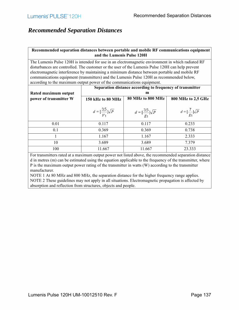
Recommended Separation Distances
Lumenis Pulse 120H UM-10012510 Rev. F Page 137
Recommended Separation Distances
Recommended separation distances between portable and mobile RF communications equipment and the Lumenis Pulse 120H
The Lumenis Pulse 120H is intended for use in an electromagnetic environment in which radiated RF disturbances are controlled. The customer or the user of the Lumenis Pulse 120H can help prevent electromagnetic interference by maintaining a minimum distance between portable and mobile RF communications equipment (transmitters) and the Lumenis Pulse 120H as recommended below, according to the maximum output power of the communications equipment.
Rated maximum output power of transmitter W
Separation distance according to frequency of transmitterm
150 kHz to 80 MHz 80 MHz to 800 MHz 800 MHz to 2,5 GHz
0.01 0.117 0.117 0.2330.1 0.369 0.369 0.7381 1.167 1.167 2.33310 3.689 3.689 7.379
100 11.667 11.667 23.333For transmitters rated at a maximum output power not listed above, the recommended separation distance d in metres (m) can be estimated using the equation applicable to the frequency of the transmitter, where P is the maximum output power rating of the transmitter in watts (W) according to the transmitter manufacturer. NOTE 1 At 80 MHz and 800 MHz, the separation distance for the higher frequency range applies. NOTE 2 These guidelines may not apply in all situations. Electromagnetic propagation is affected by absorption and reflection from structures, objects and people.