holography: the next disruptive technologyautostereoscopy, volumetric display, and holographic...
TRANSCRIPT
ARL-TR-8007 ● APR 2017
US Army Research Laboratory
Holography: The Next Disruptive Technology
by Tomoko Sano Approved for public release; distribution is unlimited.

ii
NOTICES
Disclaimers
The findings in this report are not to be construed as an official Department of the Army position unless so designated by other authorized documents. Citation of manufacturer’s or trade names does not constitute an official endorsement or approval of the use thereof. Destroy this report when it is no longer needed. Do not return it to the originator.

ARL-TR-8007 ● APR 2017
US Army Research Laboratory
Holography: The Next Disruptive Technology
by Tomoko Sano Weapons and Materials Research Directorate, ARL Approved for public release; distribution is unlimited.

ii
REPORT DOCUMENTATION PAGE Form Approved OMB No. 0704-0188
Public reporting burden for this collection of information is estimated to average 1 hour per response, including the time for reviewing instructions, searching existing data sources, gathering and maintaining the data needed, and completing and reviewing the collection information. Send comments regarding this burden estimate or any other aspect of this collection of information, including suggestions for reducing the burden, to Department of Defense, Washington Headquarters Services, Directorate for Information Operations and Reports (0704-0188), 1215 Jefferson Davis Highway, Suite 1204, Arlington, VA 22202-4302. Respondents should be aware that notwithstanding any other provision of law, no person shall be subject to any penalty for failing to comply with a collection of information if it does not display a currently valid OMB control number. PLEASE DO NOT RETURN YOUR FORM TO THE ABOVE ADDRESS.
1. REPORT DATE (DD-MM-YYYY)
April 2017 2. REPORT TYPE
Technical Report 3. DATES COVERED (From - To)
1–30 September 2016 4. TITLE AND SUBTITLE
Holography: The Next Disruptive Technology 5a. CONTRACT NUMBER
5b. GRANT NUMBER
5c. PROGRAM ELEMENT NUMBER
6. AUTHOR(S)
Tomoko Sano 5d. PROJECT NUMBER
5e. TASK NUMBER
5f. WORK UNIT NUMBER
7. PERFORMING ORGANIZATION NAME(S) AND ADDRESS(ES)
US Army Research Laboratory ATTN: RDRL-WMM-F Aberdeen Proving Ground, MD 21005-5069
8. PERFORMING ORGANIZATION REPORT NUMBER
ARL-TR-8007
9. SPONSORING/MONITORING AGENCY NAME(S) AND ADDRESS(ES)
10. SPONSOR/MONITOR'S ACRONYM(S)
11. SPONSOR/MONITOR'S REPORT NUMBER(S)
12. DISTRIBUTION/AVAILABILITY STATEMENT
Approved for public release; distribution is unlimited. 13. SUPPLEMENTARY NOTES
14. ABSTRACT
Camouflage has been used by the US Army for years for concealment and obscuring objects. Though effective, this is a relatively simple passive-defense tactic with limitations. Augmenting or manipulating reality to confuse and deceive the enemy would be the next innovative step forward. Is it possible in the future to create a deceptive holographic army or a holographic concealment in the battlefield? Using a 2-D screen and holograms for training purposes and for meeting face to face, as well as touchscreen haptic holographic displays, are already possible. The ability to project true holographic 3-D objects in air using femtosecond lasers that can be viewed from all 360° angles was just developed. What is the timeline and what are the technological gaps that must be solved before holographic innovations can revolutionize visual deception? And, how much shorter is the timeline for holography’s use for training and communication applications without using special headsets or glasses? What are the promising methods and extent of capabilities of the various holographic projections being developed today? The objective of this deep dive is to search, review, and assess the current and rapidly changing technological advances in holography and how it could transform the Army’s in-theater tactics as well as training and communication. 15. SUBJECT TERMS
holography, volumetric display, holographic display, 3-D projection, augmented reality, visual deception
16. SECURITY CLASSIFICATION OF: 17. LIMITATION OF ABSTRACT
UU
18. NUMBER OF PAGES
24
19a. NAME OF RESPONSIBLE PERSON
Tomoko Sano a. REPORT
Unclassified b. ABSTRACT
Unclassified c. THIS PAGE
Unclassified 19b. TELEPHONE NUMBER (Include area code)
410-306-0726 Standard Form 298 (Rev. 8/98)
Prescribed by ANSI Std. Z39.18

Approved for public release; distribution is unlimited. iii
Contents
List of Figures iv
List of Tables iv
1. Introduction 1
2. Part I: Materials 2
3. Part II: Volumetric and Holographic Displays 5
4. Applications 9
5. Conclusions 11
6. References 12
List of Symbols, Abbreviations, and Acronyms 16
Distribution List 17

Approved for public release; distribution is unlimited. iv
List of Figures
Fig. 1 Solid-state upconversion: (a) energy-level diagram of an activated ion and (b) 2 intersecting laser beams with different wavelengths are absorbed in ZBLAN ...............................................................................2
Fig. 2 Schematic of the optical-fiber-bundle-based static volumetric 3-D display ....................................................................................................3
Fig. 3 Volumetric display: (a) schematic, (b) cylindrical fog-screen apparatus, (c) CGH image, and (d) rendered holographic image ..........6
Fig. 4 (a) Drawing and photograph showing the femtosecond-laser-induced hologram setup where (1) is the femtosecond laser; (2) SLM; (3), (4), (6), and (7) lenses; (5) Galvano scanner, (8) mirror, and (9) the objective and the varifocal lens. (b) Photograph showing the projected voxels with illustrations showing the voxel area and the beam emitting the plasma. (c) Rendered heart that, once touched, splits into 2 ovals. .7
Fig. 5 (a) Light-field display and (b) resulting holograph of a pink doll next to a real panda figure..............................................................................8
Fig. 6 Example hologram rendered by Voxiebox ............................................9
Fig. 7 RealView’s interactive dragon ...............................................................9
List of Tables
Table 1 Digital hologram SLM types and mechanisms ......................................3
Table 2 Holographic recording materials and their properties ...........................5
Approved for public release; distribution is unlimited. 1
1. Introduction
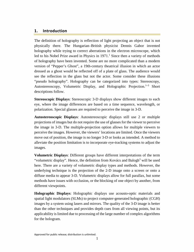
The definition of holography is reflection of light projecting an object that is not physically there. The Hungarian–British physicist Dennis Gabor invented holography while trying to correct aberrations in the electron microscope, which led to his Nobel Prize award in Physics in 1971.1 Since then a variety of methods of holography have been invented. Some are no more complicated than a modern version of “Pepper’s Ghost”, a 19th-century theatrical illusion in which an actor dressed as a ghost would be reflected off of a plate of glass. The audience would see the reflection in the glass but not the actor. Some consider these illusions “pseudo holography”. Holography can be categorized into types: Stereoscopy, Autostereoscopy, Volumetric Display, and Holographic Projection.1–3 Short descriptions follow.
Stereoscopic Displays: Stereoscopic 3-D displays show different images to each eye, where the image differences are based on a time sequence, wavelength, or polarization. Special glasses are required to perceive the image in 3-D.
Autostereoscopic Displays: Autostereoscopic displays still use 2 or multiple projections of images but do not require the use of glasses for the viewer to perceive the image in 3-D. The multiple-projection option allows for multiple viewers to perceive the images. However, the viewers’ locations are limited. Once the viewers move out of position, the image is no longer 3-D or looks as intended. A method to alleviate the position limitation is to incorporate eye-tracking systems to adjust the images.
Volumetric Displays: Different groups have different interpretations of the term “volumetric display”. Hence, the definition from Kovács and Balogh3 will be used here. There are a variety of volumetric display types and methods. However, the underlying technique is the projection of the 2-D image onto a screen or onto a diffuse media to appear 3-D. Volumetric displays allow for full parallax, but some methods have issues with occlusion, or the blocking of one object by another, from different viewpoints.
Holographic Displays: Holographic displays use acousto-optic materials and spatial light modulators (SLMs) to project computer-generated holographic (CGH) images by a system using lasers and mirrors. The quality of the 3-D image is better than the other techniques and provides depth cues from all viewing points, but its applicability is limited due to processing of the large number of complex algorithms for the hologram.
Approved for public release; distribution is unlimited. 2
Part I of this report will focus on materials and chemistries investigated for these displays, and in Part II the techniques of volumetric and holographic displays will be covered. More details of the other techniques can be found in Yang et al.1
2. Part I: Materials
The materials solutions for the holographic display technology are varied and dictated by the technology behind the holographic display. Some of the materials requirements and solutions for holographic display covered by Geng4 and others are described in the following.
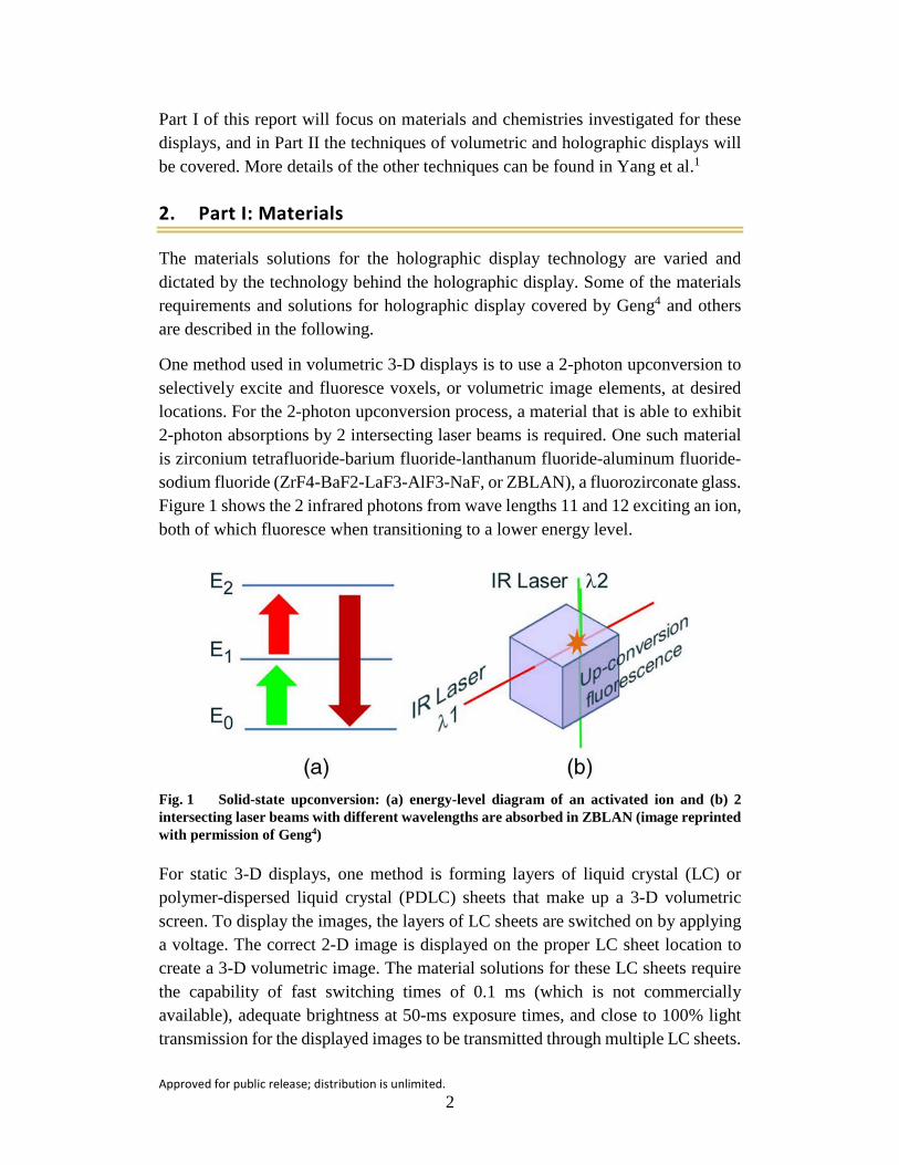
One method used in volumetric 3-D displays is to use a 2-photon upconversion to selectively excite and fluoresce voxels, or volumetric image elements, at desired locations. For the 2-photon upconversion process, a material that is able to exhibit 2-photon absorptions by 2 intersecting laser beams is required. One such material is zirconium tetrafluoride-barium fluoride-lanthanum fluoride-aluminum fluoride-sodium fluoride (ZrF4-BaF2-LaF3-AlF3-NaF, or ZBLAN), a fluorozirconate glass. Figure 1 shows the 2 infrared photons from wave lengths 11 and 12 exciting an ion, both of which fluoresce when transitioning to a lower energy level.
Fig. 1 Solid-state upconversion: (a) energy-level diagram of an activated ion and (b) 2 intersecting laser beams with different wavelengths are absorbed in ZBLAN (image reprinted with permission of Geng4)
For static 3-D displays, one method is forming layers of liquid crystal (LC) or polymer-dispersed liquid crystal (PDLC) sheets that make up a 3-D volumetric screen. To display the images, the layers of LC sheets are switched on by applying a voltage. The correct 2-D image is displayed on the proper LC sheet location to create a 3-D volumetric image. The material solutions for these LC sheets require the capability of fast switching times of 0.1 ms (which is not commercially available), adequate brightness at 50-ms exposure times, and close to 100% light transmission for the displayed images to be transmitted through multiple LC sheets.

Approved for public release; distribution is unlimited. 3
Another method for static 3-D displays is a 3-D glass cube embedded with optical fibers, as shown in Fig. 2. In this display, the germano-silicate optical fibers are used to control the 3-D voxel arrays, which are made from optical resin. The image signal is controlled by SLM, which also can have a variety of material solutions.
Fig. 2 Schematic of the optical-fiber-bundle-based static volumetric 3-D display (image reprinted with permission of Geng4)
The SLM spatially varies the light intensity and/or the phase and is the key component in displaying CGH. There are a variety of SLM mechanisms, as shown in Table 1.
Table 1 Digital hologram SLM types and mechanisms4
SLM type Modulation mechanism Digital light processing . . . Liquid crystal on silicon Electronically controlled Ferroelectric liquid crystal on silicon . . . Acousto-optic modulator Acoustically controlled Optically addressed spatial light modulator Optically controlled Magneto-optical spatial light modulator Magneto-optically controlled
Ferroelectric crystal on silicon substrate has been used for electrically addressed spatial light modulators, and optically addressed spatial light modulators use a chalcogenide glass family of materials such as amorphous arsenic trisulfide.5 However, hydrogenated amorphous silicon film, bismuth silicon oxide, crystalline silicon, arsenic-selenium, phthalocyanine, and zinc oxide nanoparticle suspensions on an indium tin oxide-coated glass substrate have also been used for the photosensors.6 For magneto-optic SLMs, layers of silicon nickel and amorphous terbium-iron thin films on silicon dioxide substrates7 and bismuth-substituted yttrium-iron-garnet thin films have been used.8

Approved for public release; distribution is unlimited. 4
A Massachusetts Institute of Technology (MIT) group developed a new SLM design with improvements in bandwidth, viewing angle, image quality, and color multiplexing. Their holographic scanner design, called the guided wave scanner (GWS), uses a proton-exchanged channel waveguide on a lithium niobate (LiNbO3) substrate with a transducer at one end. The GWS consists of 2 sets of acoustic transducers to create surface acoustic waves that deflect light horizontally and vertically.9 Other research groups10,11 have investigated the application of lithium tantalite (LiTaO3) or magnesium-oxide-doped LiTaO3 thin film single crystals for the wave guide.
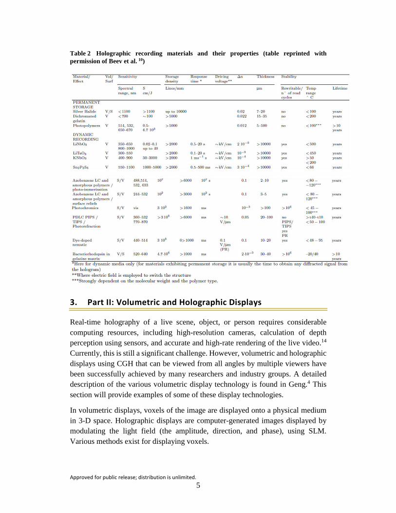
Other areas of materials development for holographic technology are for recording media applications. Beev et al.10 details the variety and requirements of photosensitive materials and recording media, but the following is a short synopsis. For a material to be a candidate for a holographic recording media, several factors need to be considered: spatial resolution, diffraction efficiency, modulation transfer function, exposure sensitivity, and noise in the diffracted or scattered wave. One of the best materials for holographic recording media is silver halide emulsions, though they are difficult to produce due to thermodynamic instability.12 Polymers have also been well-established as photosensitive materials, including photoresists, photochromic azopolymers, anthracene-containing polymers, and photopolymers. In the area of inorganic materials for holographic recordings, there are photorefractive crystals such as doped or undoped LiNbO3 (and other niobates13) and LiTaO3 (mentioned earlier), barium titanate, and other barium-based titanates. Various molecular weight and doped LC, as well as PDLC with different concentrations of LC or LC droplet morphologies, are also being investigated for holographic recording media applications. Table 2 lists the various materials and the properties of each.
Approved for public release; distribution is unlimited. 5
Table 2 Holographic recording materials and their properties (table reprinted with permission of Beev et al. 10)
3. Part II: Volumetric and Holographic Displays
Real-time holography of a live scene, object, or person requires considerable computing resources, including high-resolution cameras, calculation of depth perception using sensors, and accurate and high-rate rendering of the live video.14 Currently, this is still a significant challenge. However, volumetric and holographic displays using CGH that can be viewed from all angles by multiple viewers have been successfully achieved by many researchers and industry groups. A detailed description of the various volumetric display technology is found in Geng.4 This section will provide examples of some of these display technologies.
In volumetric displays, voxels of the image are displayed onto a physical medium in 3-D space. Holographic displays are computer-generated images displayed by modulating the light field (the amplitude, direction, and phase), using SLM. Various methods exist for displaying voxels.

Approved for public release; distribution is unlimited. 6
One example is drawing a voxel on microbubbles. Kumagai and Hayasaki use a femtosecond laser to excite a high-viscosity glycerin screen by multiphoton absorption. This causes microbubbles to form, and with 3-D laser beam scanning to vary the focal points the volume of voxels renders the high-resolution CGH image.15 Another technique is to use fog or water vapor as the medium to display the CGH image.16,17 The fog screen can be adjusted for density to control opacity. Some fog screens used for entertainment can be 2 m wide, and several screens can be “linked” together for a larger image. Some fog screens are essentially 2-D screens projecting a pseudo 3-D image, but others are true 3-D projections. The fog screen created by Zeng et al.17 is cylindrical, and several kinoforms of the sliced volumetric object are calculated by the slice-based fresnel diffraction algorithm. The 3-D image is reconstructed using an LCSLM and rendered onto the fog screen. Figure 3 shows the schematic of the technique and the cylindrical fog screen apparatus.
Fig. 3 Volumetric display: (a) schematic, (b) cylindrical fog-screen apparatus, (c) CGH image, and (d) rendered holographic image (images reprinted with permission of Zeng et al.17)
Instead of using fog as a screen, some researchers are demonstrating volumetric displays with plasma. Saito et al.18 and Ochiai et al.19 have rendered aerial 3-D displays using plasma generated by a femtosecond laser. In their system, Ochiai et al. use the laser-induced plasma for the light emission and SLM and scan the

Approved for public release; distribution is unlimited. 7
laser with a Galvano mirror to render the holographic images. The drawback is that currently the rendered volume is limited to 1 cm3. However, interaction with the hologram is possible and causes a plasma-generated haptic sensation. A diagram of Ochiai et al.’s setup as well as the rendered image is shown in Fig. 4.
Fig. 4 (a) Drawing and photograph showing the femtosecond-laser-induced hologram setup where (1) is the femtosecond laser; (2) SLM; (3), (4), (6), and (7) lenses; (5) Galvano scanner, (8) mirror, and (9) the objective and the varifocal lens. (b) Photograph showing the projected voxels with illustrations showing the voxel area and the beam emitting the plasma. (c) Rendered heart that, once touched, splits into 2 ovals. (Images reprinted with permission of Ochiai et al.19)
Another technique is projection of the holographic image in a light field.19–23 This can be accomplished by several methods. One method used by Miyazaki et al. and Maeda et al. is using a dihedral corner reflector array that converges light from a point light source to a location where the 3-D image is projected.21,22 Other methods use a screen and multiple projectors23 or a projector and a moving screen that diffuses the light, creating a light field.24 The schematic of the moving-screen light-field technique and the resulting holographic image is shown in Fig. 5.

Approved for public release; distribution is unlimited. 8
Fig. 5 (a) Light-field display and (b) resulting holograph of a pink doll next to a real panda figure (images reprinted with permission of Xia et al.23)
There are several commercially available volumetric and holographic displays. One is Voxon’s Voxiebox, which uses a laser with a moving screen similar to that of Xia et al.23 It can project over half a billion voxels of a “moving” image every second into the 18 × 18 × 8 (xyz in cm) volumetric display area. An example of a Voxiebox hologram is shown in Fig. 6. Another is RealView, having the benefit of being interactive, which uses digital holography for displaying full-color images. Figure 7 shows the hologram of a dragon that can flap its wings and be rotated by the viewer. There are many companies working on holographic or 3-D volumetric displays, including Google, Microsoft, Samsung, Intel, Apple, Sony, Qualcomm, Zebra, Leia Display Systems, SeeReal, Heloxica Inc., LightSpace Technologies Inc., and Actuality Systems Inc. Several US universities conduct significant efforts in this area as well, including the MIT Media Lab, the University of Southern California Institute for Creative Technology, and the University of Arizona.

Approved for public release; distribution is unlimited. 9
Fig. 6 Example hologram rendered by Voxiebox (image reprinted with permission of Voxiebox25)
Fig. 7 RealView’s interactive dragon (image reprinted with permission of RealView26)
4. Applications
The current major driver for the holographic and volumetric display technology is for entertainment applications, such as 3-D TV and movies, gaming, and mobile devices. However, development is also underway for applications in the medical industry, marketing and advertising, and training, especially when haptic feedback27,28 is incorporated into the interaction with the projected image. An area where a holographic technology has already been used, albeit in a pseudo-hologram projected onto a screen, is communication.
Approved for public release; distribution is unlimited. 10
However they are used in classrooms, holographic projections have some limitations. A recent, small study in South America evaluated the use of holographic projections in education.29 Although only 22 students participated in the study, their responses to the use of holographic technology were mixed: 81% stated that they “felt” the presence of the professor when corresponding with the holographic teacher, while 95% of the students accepted the temporary use of a holographic professor in a situation where the professor was not physically available, such as due to travel. However, 58% of the students who attended at least 5 classes stated that the novelty wore off and they began to lose interest. Only 42% of the students believed they achieved the same amount of learning from a holographic professor as from a physical professor.
When holography is applied as part of a learning or training tool, the benefits are clear. For example, in medical training, if students can interact with a realistic hologram of an organ or body, it would enhance their education. If medical students could perform surgery on a 3-D hologram without the risk of harming a real human, this technology would be a clear benefit to society. Similarly, holographic projections and 3-D displays could be used in military training applications. In fact, under the Urban Photonic Sandtable Display Program, the US Defense Advanced Research Projects Agency partnered with Zebra Imaging to produce a prototype of the ZScape Motion Display for a real-time streaming of 3-D holographic battle locations for better planning.30 Another benefit for military applications is using augmented virtual reality to reduce the cost of training, such as live-fire training, or to recreate difficult situational training scenarios. Recently, the Office of Naval Research’s Augmented Immersive Team Training project, started in fiscal year 2011, produced and transitioned the prototype of a more accurate virtual reality training simulation for the Marines to Program Manager for Training Systems. But this prototype still requires the use of a head-worn display. If this system could be created as an autostereoscopic holographic system, without the need for a cumbersome head-worn display, the training could be more effective.31
Other military applications include in-theater deceptive tactics. If the holographic technology advances to where holographic systems could be portable, the display large enough, and the resolution high enough, holograms could be used as camouflage or to augment reality for deception.
Approved for public release; distribution is unlimited. 11
5. Conclusions
There is significant growth in the research and development of holographic (and 3-D volumetric) display technology. In fact, a market research report published in 2015 by Markets and Markets on the holographic display market,32 estimates that the holographic technology market will grow to an estimated $3.57 billion by 2020 and grow at a compound annual growth rate of 30.23% from 2014 to 2020. This growth is expected to be led by holographic technology for medical applications and consumer electronics. Similarly, for the volumetric display market, it is expected to reach $348.2 million by 2020 at a compound annual growth rate of 33.28% from 2015 to 2020.33 That being said, the maturity of the holographic technology is still in its infancy. Although holographic projections for communications and entertainment have been achieved with a simplified projection onto a 2-D screen, this technology is just an improvement on Pepper’s Ghost. This may be sufficient for communication, but we are few years away from applying holography as an effective training tool. For holography to be applied for the military’s disruptive augmented-reality applications, more research and development are needed. The resolution of the projected image, the size capability of the projection, and computing power are still lacking. However, this technology is rapidly advancing, and in the not-too-distant future, an interactive holography could be part of in-theater deceptive and camouflaging techniques.
Approved for public release; distribution is unlimited. 12
6. References
1. Yang L, Dong H, Alelaiwi A, El Saddik A. See in 3D: state of the art of 3D display technologies. Multimed Tools Appl. 2016;75(24):17121–17155.
2. Luckhurst M, Morin E. Introduction: Theatre and Spectrality. In: Luckhurst M, Morin E, editors. Theatre and ghosts materiality, performance and modernity. London (England): Palgrave Macmillan UK; 2014. p. 19.
3. Kovács PT, Balogh T. 3D visual experience. In: Mrak M, Grgic M, Kunt M, editors. High-quality visual experience. Berlin (Germany): Springer-Verlag; 2010. p. 391–410.
4. Geng J. Three-dimensional display technologies. Advances in Optics and Photonics. 2013;5:456–535.
5. Kirzhner MG, Klebanov M, Lyubin V, Collings N, Abdulhalim I. Liquid crystal high-resolution optically addressed spatial light modulator using a nanodimensional chalcogenide photosensor. Optics Letters. 2014;39(7).
6. Shrestha PK, Chun YT, Chu D. A high-resolution optically addressed spatial light modulator based on ZnO nanoparticles. Light: Science & Applications. 2015;4:e259.
7. Takagi H, Nakamura K, Goto T, Lim PB, Inoue M. Magneto-optic spatial light modulator with submicron-size magnetic pixels for wide-viewing-angle holographic displays. Optics Letters. 2014;39(11):3344–3347.
8. Simon M. A MEMS Faraday rotator for MEMS polarization controllers, MEMS magneto-optic spatial light modulators and other enabled technologies [accessed 2007]. http://www.colorado.edu/MCEN/MEMSII/IndProj/MEMS %20Magneto_Simon.pdf.
9. Smalley DE. High-resolution spatial light modulation for holographic video [master’s thesis]. Cambridge (MA): Massachusetts Institute of Technology; 2008.
10. Beev KS, Beeva KN, Sainov SH. Materials for holographic 3DTV display applications. In: Ozaktas HM, Onural L, editors. Three-dimensional television capture, transmission, display. Berlin (Germany): Springer-Verlag; 2008. p. 557–597.

Approved for public release; distribution is unlimited. 13
11. Okazaki M, Yoshimoto S, Chichibu T, Suhara T. Electro-optic spatial light modulator using periodically poled MgO:s-LiTaO3 waveguide. IEEE Photon Tech Lett P. 2015;27(15):1646–1648.
12. Petrova T, Ivanov B, Zdravkov K, Nazarova D, Stoykova E, Minchev G, Sainov V. Basic holographic characteristics of a panchromatic light sensitive material for reflective autostereoscopic 3D display. EURASIP Journal on Advances in Signal Processing; 2009. Article ID 217341. doi:10.1155/2009/217341.
13. Sasaura M, Horikoshi T, Ono M, Imai T, Yagi S, Kubota E, Tate A, Kojima H, Sonehara N. Proposal and demonstration of cached holographic 3D display system using photorefractive crystals. Journal of Crystal Growth. 2001;229:199–204.
14. Kim S-Y, Koschan A, Abidi MA, Ho*Y-S. High quality visual experience. In: Mrak M, Grgic M, Kunt M, editors. High-quality visual experience: creation, processing and interactivity of high-resolution and high-dimensional video signals. New York (NY): Springer; 2010. p. 348–369.
15. Kumagai K, Hayasaki Y. Bubble display: volumetric graphics in high-viscosity liquid rendered by holographic femtosecond laser-induced bubbles. In: Imaging and applied optics. Lakeland (TN): Optical Society of America (OSA) Technical Digest; 2016. Paper No.: TW1A.2.
16. Rakkolainen I. Pseudo-volumetric 3D display solutions. In: Chen J, Cranton W, Fihn M, editors. Handbook of visual display technology. Berlin (Germany): Springer-Verlag; 2012. p. 1934–1941.
17. Zeng Z, Zheng H, Lu X, Gao H, Yu Y. Dynamic holographic three-dimensional projection based on liquid crystal spatial light modulator and cylindrical fog screen. Opt Rev. 2015;22:853–861.
18. Saito H, Kimura H, Shimada S, Naemura T, Kayahara J, Jarusirisawad S, Nozick V, Ishikawa H, Murakami T, Aoki J, et al. Laser-plasma scanning 3D display for putting digital contents in free space. In: Woods AJ, Holliman NS, Merritt JO, editors. Stereoscopic displays and applications XIX. Proceedings of SPIE-IS&T Electronic Imaging. 2008;6803.
19. Ochiai Y, Kumagai K, Hoshi T, Rekimoto J, Hasegawa S, Hayasaki Y. Fairy lights in femtoseconds: aerial and volumetric graphics rendered by focused femtosecond laser combined with computational holographic fields. ACM SIGGRAPH; 2015. Emerging Technologies Article 10. https://arxiv.org/ftp /arxiv/papers/1506/1506.06668.pdf.
Approved for public release; distribution is unlimited. 14
20. Yoshida S. fVisiOn: Glasses-free tabletop 3D display to provide virtual 3D media naturally alongside real media. In: Javidi B, Son J-Y, editors. Three-dimensional imaging, visualization, and display. Proceedings of SPIE. 2012;8384.
21. Miyazaki D, Maeda Y, Maekawa S. Floating three-dimensional image display using micro-mirror array imaging element. In: Javidi B, Son J-Y, editors. Three-dimensional imaging, visualization, and display. Proceedings of SPIE. 2015;9495.
22. Maeda Y, Miyazaki D, Maekawa S. Volumetric aerial three-dimensional display based on heterogeneous imaging and image plane scanning. Appl Optics. 2015;54(13):4109–4115.
23. Xia X, Liu X, Li H, Zheng Z, Wang H, Peng Y, Shen W. A 360-degree floating 3D display based on light field regeneration. Opt Express. 2013;21:9.
24. Lee S, Jang C, Moon S, Cho J, Lee B. Additive light field displays: realization of augmented reality with holographic optical elements. ACM Trans Graph. 2016;35:4.
25. What is Voxiebox? [accessed 2016 Aug]. www.voxiebox.com
26. Live holography [accessed 2016 Aug]. http://www.realviewimaging.com/.
27. Sinclair M, Pahud M, Benko H. TouchMover: actuated 3D touchscreen with haptic feedback. Proceedings of the ACM International Conference on Interactive Tabletops and Surfaces. New York (NY): ACM; 2013. p. 287–296.
28. Monnai Y, Hasegawa K, Fujiwara M, Yoshino K, Inoue S, Shinoda H. HaptoMime: mid-air haptic interaction with a floating virtual screen. Proceedings of ACM Conference on Interactive Tabletops and Surfaces. New York (NY): Association of Computing Machinery; 2014. p. 663–667.
29. Luévano E, López de Lara E, Castro JE. Use of telepresence and holographic projection mobile device for college degree level. Procedia Computer Science. 2015;75:339–347.
30. Lee H. 3D holographic technology and its educational potential. Tech Trends. 2013;57(4).
31. Judson J. Augmented virtual reality emerging as game changer for Marine Corps training. DefenseNews. 2015 Dec 10.

Approved for public release; distribution is unlimited. 15
32. Holographic market [accessed 2017 Mar 7]. http://www .marketsandmarkets.com/Market-Reports/holographic-market-144316799.html.
33. Volumetric display market [accessed 2017 Mar 7]. http://www .marketsandmarkets.com/Market-Reports/volumetric-display-market -248090250.html.

Approved for public release; distribution is unlimited. 16
List of Symbols, Abbreviations, and Acronyms
2-D 2-dimensional
3-D 3-dimensional
Ba barium
CGH computer-generated holographic
GWS guided wave scanner
La lanthanum
LC liquid crystal
LiNbO3 lithium niobate
LiTaO3 lithium tantalite
MIT Massachusetts Institute of Technology
Na sodium
PDLC polymer-dispersed liquid crystal
SLM spatial light modulator
ZBLAN ZrF4-BaF2-LaF3-AlF3-NaF
Zr zirconium

Approved for public release; distribution is unlimited. 17
1 DEFENSE TECHNICAL (PDF) INFORMATION CTR DTIC OCA 2 DIRECTOR (PDF) US ARMY RESEARCH LAB RDRL CIO L IMAL HRA MAIL & RECORDS MGMT 1 GOVT PRINTG OFC (PDF) A MALHOTRA 1 DIR USARL (PDF) RDRL WMM F T SANO

Approved for public release; distribution is unlimited. 18
INTENTIONALLY LEFT BLANK.