home system overview - vertivco.com · color: bright zinc plating (spec. m500-53) body, textured...
TRANSCRIPT
PD588705100, PD588705101, PD588705102, PD588705103, PD588705104 Power Data Sheet
Spec. No. 588705100 (Model PSS24/1000-23) Spec. No. 588705101 (Model PSS24/1000-23) Spec. No. 588705102 (Model PSS24/2000-23) Spec. No. 588705103 (Model PSS24/3000-23) Spec. No. 588705104 (Model PSS24/4000-23)
Issue AF, July 11, 2012
Page 1 of 32
This document is property of Emerson Network Power, Energy Systems, North America, Inc. and contains confidential and proprietary information owned by Emerson Network Power, Energy Systems, North America, Inc. Any copying, use, or disclosure of it without the written permission of Emerson Network Power, Energy Systems, North America, Inc. is strictly prohibited.
SYSTEM OVERVIEW
Preface: This document provides power data and system application information for the following Module Mounting Shelf Assemblies used in a NetSure™ Power System.
MODEL SPEC. NO. DESCRIPTION
PSS24/1000-23 588705100 8-Position Field-Expansion Module Mounting Shelf Assembly
PSS24/1000-23 588705101 8-Position Module Mounting Shelf Assembly
PSS24/2000-23 588705102 16-Position Module Mounting Shelf Assembly
PSS24/3000-23 588705103 24-Position Module Mounting Shelf Assembly
PSS24/4000-23 588705104 32-Position Module Mounting Shelf Assembly
For rectifier and converter modules, refer to their separate instruction document as indicated in the following table.
MODEL SPEC. NO. DESCRIPTION Document Number
R24-2500 1R242500 Rectifier Module (2500 watts) UM1R243000
R24-3000 1R243000 Rectifier Module (3000 watts)
C24/48-1500 1C24481500 DC-DC Converter Module UM1C24481500
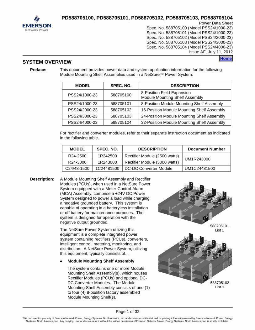
Description: A Module Mounting Shelf Assembly and Rectifier Modules (PCUs), when used in a NetSure Power System equipped with a Meter-Control-Alarm (MCA) Assembly, comprise a +24V DC Power System designed to power a load while charging a negative grounded battery. This system is capable of operating in a batteryless installation or off battery for maintenance purposes. The system is designed for operation with the negative output grounded.
The NetSure Power System utilizing this equipment is a complete integrated power system containing rectifiers (PCUs), converters, intelligent control, metering, monitoring, and distribution. A NetSure Power System, utilizing this equipment, typically consists of...
Module Mounting Shelf Assembly
The system contains one or more Module Mounting Shelf Assembly(s), which houses Rectifier Modules (PCUs) and optional DC-DC Converter Modules. The Module Mounting Shelf Assembly consists of one (1) to four (4) 8-position factory assembled Module Mounting Shelf(s).
Home
588705101 List 1
588705102 List 1
PD588705100 Power Data Sheet PD588705101 Spec. No. 588705100 (Model PSS24/1000-23) PD588705102 Spec. No. 588705101 (Model PSS24/1000-23) PD588705103 Spec. No. 588705102 (Model PSS24/2000-23) PD588705104 Spec. No. 588705103 (Model PSS24/3000-23) Issue AF, July 11, 2012 Spec. No. 588705104 (Model PSS24/4000-23)
Page 2 of 32
This document is property of Emerson Network Power, Energy Systems, North America, Inc. and contains confidential and proprietary information owned by Emerson Network Power, Energy Systems, North America, Inc. Any copying, use, or disclosure of it without the written permission of Emerson Network Power, Energy Systems, North America, Inc. is strictly prohibited.
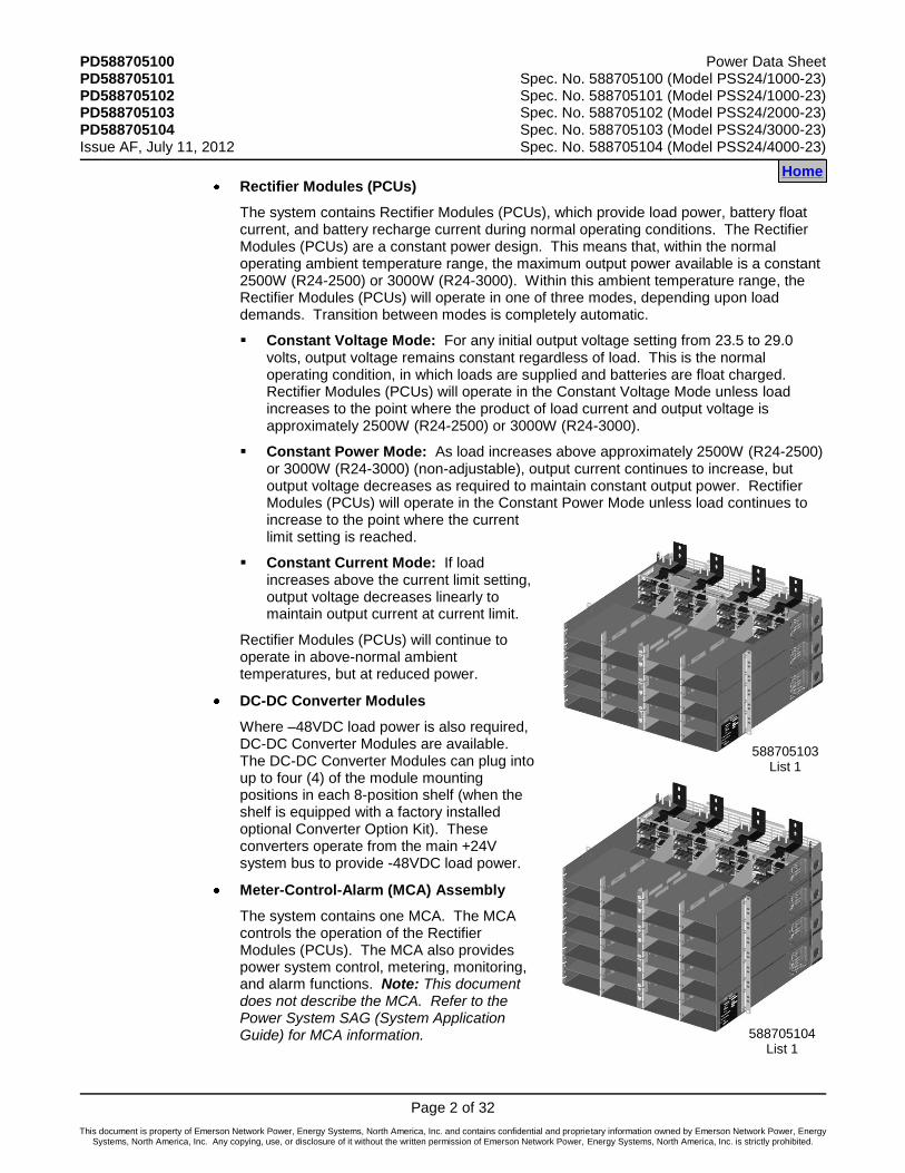
Rectifier Modules (PCUs)
The system contains Rectifier Modules (PCUs), which provide load power, battery float current, and battery recharge current during normal operating conditions. The Rectifier Modules (PCUs) are a constant power design. This means that, within the normal operating ambient temperature range, the maximum output power available is a constant 2500W (R24-2500) or 3000W (R24-3000). Within this ambient temperature range, the Rectifier Modules (PCUs) will operate in one of three modes, depending upon load demands. Transition between modes is completely automatic.
Constant Voltage Mode: For any initial output voltage setting from 23.5 to 29.0 volts, output voltage remains constant regardless of load. This is the normal operating condition, in which loads are supplied and batteries are float charged. Rectifier Modules (PCUs) will operate in the Constant Voltage Mode unless load increases to the point where the product of load current and output voltage is approximately 2500W (R24-2500) or 3000W (R24-3000).
Constant Power Mode: As load increases above approximately 2500W (R24-2500) or 3000W (R24-3000) (non-adjustable), output current continues to increase, but output voltage decreases as required to maintain constant output power. Rectifier Modules (PCUs) will operate in the Constant Power Mode unless load continues to increase to the point where the current limit setting is reached.
Constant Current Mode: If load increases above the current limit setting, output voltage decreases linearly to maintain output current at current limit.
Rectifier Modules (PCUs) will continue to operate in above-normal ambient temperatures, but at reduced power.
DC-DC Converter Modules
Where –48VDC load power is also required, DC-DC Converter Modules are available. The DC-DC Converter Modules can plug into up to four (4) of the module mounting positions in each 8-position shelf (when the shelf is equipped with a factory installed optional Converter Option Kit). These converters operate from the main +24V system bus to provide -48VDC load power.
Meter-Control-Alarm (MCA) Assembly
The system contains one MCA. The MCA controls the operation of the Rectifier Modules (PCUs). The MCA also provides power system control, metering, monitoring, and alarm functions. Note: This document does not describe the MCA. Refer to the Power System SAG (System Application Guide) for MCA information.
Home
588705103 List 1
588705104 List 1

Power Data Sheet PD588705100 Spec. No. 588705100 (Model PSS24/1000-23) PD588705101 Spec. No. 588705101 (Model PSS24/1000-23) PD588705102 Spec. No. 588705102 (Model PSS24/2000-23) PD588705103 Spec. No. 588705103 (Model PSS24/3000-23) PD588705104 Spec. No. 588705104 (Model PSS24/4000-23) Issue AF, July 11, 2012
Page 3 of 32
This document is property of Emerson Network Power, Energy Systems, North America, Inc. and contains confidential and proprietary information owned by Emerson Network Power, Energy Systems, North America, Inc. Any copying, use, or disclosure of it without the written permission of Emerson Network Power, Energy Systems, North America, Inc. is strictly prohibited.
NetSure™ Distribution
Provides DC distribution through fuses and/or circuit breakers. Note: This document does not describe NetSure Distribution. Refer to the Power System SAG (System Application Guide) for distribution information.
Family: NetSure™
Spec. Nos.: 588705100, 588705101, 588705102, 588705103, 588705104
Model: PSS24/1000-23, PSS24/2000-23, PSS24/3000-23, PSS24/4000-23
Rectifier Input Voltage Nominal 208-240 volts AC, single phase, 50/60 Hz, with an operating range of 180 to 264 volts. Acceptable input frequency range is 47 to 65 Hz.
Rectifier Output Voltage: +24 Volts DC
Converter Output Voltage: -48 Volts DC
Rectifier Output Capacity: Rectifier Module (PCU) (R24-2500): 87.7A @ +28.5VDC to 104.2A @ +24.0VDC, 2500 Watts Rectifier Module (PCU) (R24-3000): 105.3A @ +28.5VDC to 125.0A @ +24.0VDC, 3000 Watts Module Mounting Shelf Assembly: Varies - see individual List Descriptions
Optional DC-DC Converter Module Output Capacity:
DC-DC Converter Module: 31 Amperes (1500W) Module Mounting Shelf Assembly: Varies - see individual List Descriptions
Agency Approval: UL 60950 Recognized; CAN/CSA 22.2, No. 60950-00, NEBS
Framework Type: For Mounting in a 23-Inch Wide Relay Rack
Mounting Width: 23 Inch (Relay Rack Mounting)
Mounting Depth: 22.34 Inches
Front Projection: 6.23 Inches, fixed
Mounting Height: 588705100 and 588705101: 3-1/2 Inches (2RU) 588705102: 7 Inches (4RU) 588705103: 10-1/2 Inches (6RU) 588705104: 14 Inches (8RU)
Access: Front and Rear for Installation and Maintenance, Front for Operation
Control: Microprocessor
Color: Bright Zinc Plating (Spec. M500-53) Body, Textured Gray (Spec. M500-147) Faceplates
Environment: -40°C to +40°C (-40°F to +104°F)
Home

PD588705100 Power Data Sheet PD588705101 Spec. No. 588705100 (Model PSS24/1000-23) PD588705102 Spec. No. 588705101 (Model PSS24/1000-23) PD588705103 Spec. No. 588705102 (Model PSS24/2000-23) PD588705104 Spec. No. 588705103 (Model PSS24/3000-23) Issue AF, July 11, 2012 Spec. No. 588705104 (Model PSS24/4000-23)
Page 4 of 32
This document is property of Emerson Network Power, Energy Systems, North America, Inc. and contains confidential and proprietary information owned by Emerson Network Power, Energy Systems, North America, Inc. Any copying, use, or disclosure of it without the written permission of Emerson Network Power, Energy Systems, North America, Inc. is strictly prohibited.
588705100, 588705101, 588705102, 588705103, 588705104 Home
Module Mounting Shelf Assembly 588705100, List 1 (8-position, expansion) 588705101, List 1 (8-position, shown) 588705102, List 1 (16-position) 588705103, List 1 (24-position) 588705104, List 1 (32-position)
2500W Rectifier Module (PCU) 1R242500 OR 3000W Rectifier Module (PCU) 1R243000
Optional DC-DC Converter Module (requires Converter Option Kit) 1C24481500 OR 2500W Rectifier Module (PCU) 1R242500 OR 3000W Rectifier Module (PCU) 1R243000
See Also
System Overview
Table of Contents
List Descriptions
Accessory Descriptions
Specifications
Physical Size Information
Related Documentation

Power Data Sheet PD588705100 Spec. No. 588705100 (Model PSS24/1000-23) PD588705101 Spec. No. 588705101 (Model PSS24/1000-23) PD588705102 Spec. No. 588705102 (Model PSS24/2000-23) PD588705103 Spec. No. 588705103 (Model PSS24/3000-23) PD588705104 Spec. No. 588705104 (Model PSS24/4000-23) Issue AF, July 11, 2012
Page 5 of 32
This document is property of Emerson Network Power, Energy Systems, North America, Inc. and contains confidential and proprietary information owned by Emerson Network Power, Energy Systems, North America, Inc. Any copying, use, or disclosure of it without the written permission of Emerson Network Power, Energy Systems, North America, Inc. is strictly prohibited.
TABLE OF CONTENTS
System Overview
Picture List
Descriptions Accessory
Descriptions Specifications
Physical Size Information
Related Documentation
SYSTEM OVERVIEW................................................................................................................................................. 1
TABLE OF CONTENTS ............................................................................................................................................. 5
LIST DESCRIPTIONS ................................................................................................................................................ 7 List Numbers ........................................................................................................................................................ 7
588705100 List 1: Field Expansion Kit (8-Position Module Mounting Shelf Assembly) ................................. 7 588705101 List 1: 8-Position Module Mounting Shelf Assembly .................................................................... 8 588705102 List 1: 16-Position Module Mounting Shelf Assembly .................................................................. 9 588705103 List 1: 24-Position Module Mounting Shelf Assembly ................................................................ 10 588705104 List 1: 32-Position Module Mounting Shelf Assembly ................................................................ 12
ACCESSORY DESCRIPTIONS ............................................................................................................................... 14 Rectifier and Converter Modules ..................................................................................................................... 14
Part No. 1R242500: 2500W Rectifier Module ................................................................................................ 14 Part No. 1R243000: 3000W, Rectifier Module ............................................................................................... 14 Part No. 1C24481500: 1500W Converter Module ......................................................................................... 14
Module Mounting Position Blank Cover Panel (P/N 540959) ........................................................................ 15 DC-DC Converter Option Interface Component Kit (P/N 540806) ................................................................. 15 Battery Charge Temperature Compensation Probe for Single Probe Digital Compensation ................... 16 Battery Charge Temperature Compensation Probe Concentrator for Multiple Probe Use (TXM) ............ 17
Battery Temperature Probe Concentrator Kit (P/N 524570) .......................................................................... 17 Analog Battery Temperature Probe (P/N 521262) ......................................................................................... 17 TXM Extension Cable (P/N 514153) .............................................................................................................. 17
Replacement Cables ......................................................................................................................................... 18 Replacement Components ............................................................................................................................... 18 Wiring Notes ...................................................................................................................................................... 19
AC Input Branch Circuit Protection and Wire Size Selection ......................................................................... 19 Shelf Frame Ground Wire Size Selection ...................................................................................................... 20 DC Output Connections: +24VDC System Output ....................................................................................... 20 DC Output Connections: –48VDC Subsystem Output .................................................................................. 20 External Alarms Wire Size Selection.............................................................................................................. 20
Wiring Illustrations ............................................................................................................................................ 21 AC Input and Frame Ground (for each 8-Position Module Mounting Shelf in the Module Mounting Shelf Assembly) ............................................................................................................................................. 21 DC Output ...................................................................................................................................................... 22 Alarm/Control to MCA .................................................................................................................................... 22
SPECIFICATIONS .................................................................................................................................................... 23 1. Rectifier Specifications ................................................................................................................................ 23 2. DC-DC Converter Specifications ................................................................................................................. 23 3. Module Mounting Shelf Specifications ....................................................................................................... 23
3.1 Environmental Ratings ............................................................................................................................. 23 3.2 Compliance Information ........................................................................................................................... 24
PHYSICAL SIZE INFORMATION ............................................................................................................................ 25 Overall Dimensions ........................................................................................................................................... 25

PD588705100 Power Data Sheet PD588705101 Spec. No. 588705100 (Model PSS24/1000-23) PD588705102 Spec. No. 588705101 (Model PSS24/1000-23) PD588705103 Spec. No. 588705102 (Model PSS24/2000-23) PD588705104 Spec. No. 588705103 (Model PSS24/3000-23) Issue AF, July 11, 2012 Spec. No. 588705104 (Model PSS24/4000-23)
Page 6 of 32
This document is property of Emerson Network Power, Energy Systems, North America, Inc. and contains confidential and proprietary information owned by Emerson Network Power, Energy Systems, North America, Inc. Any copying, use, or disclosure of it without the written permission of Emerson Network Power, Energy Systems, North America, Inc. is strictly prohibited.
Module Mounting Shelf Assembly Spec. No. 588705100 .............................................................................. 25 Module Mounting Shelf Assembly Spec. No. 588705101 .............................................................................. 26 Module Mounting Shelf Assembly Spec. No. 588705102 .............................................................................. 27 Module Mounting Shelf Assembly Spec. No. 588705103 .............................................................................. 28 Module Mounting Shelf Assembly Spec. No. 588705104 .............................................................................. 29 Digital Battery Charge Temperature Compensation Probe (P/N 107021 and 106824) ................................. 30 Analog Battery Temperature Probe (P/N 521262) ......................................................................................... 30
RELATED DOCUMENTATION ................................................................................................................................ 31
REVISION RECORD ................................................................................................................................................ 32
Power Data Sheet PD588705100 Spec. No. 588705100 (Model PSS24/1000-23) PD588705101 Spec. No. 588705101 (Model PSS24/1000-23) PD588705102 Spec. No. 588705102 (Model PSS24/2000-23) PD588705103 Spec. No. 588705103 (Model PSS24/3000-23) PD588705104 Spec. No. 588705104 (Model PSS24/4000-23) Issue AF, July 11, 2012
Page 7 of 32
This document is property of Emerson Network Power, Energy Systems, North America, Inc. and contains confidential and proprietary information owned by Emerson Network Power, Energy Systems, North America, Inc. Any copying, use, or disclosure of it without the written permission of Emerson Network Power, Energy Systems, North America, Inc. is strictly prohibited.
LIST DESCRIPTIONS
List Numbers
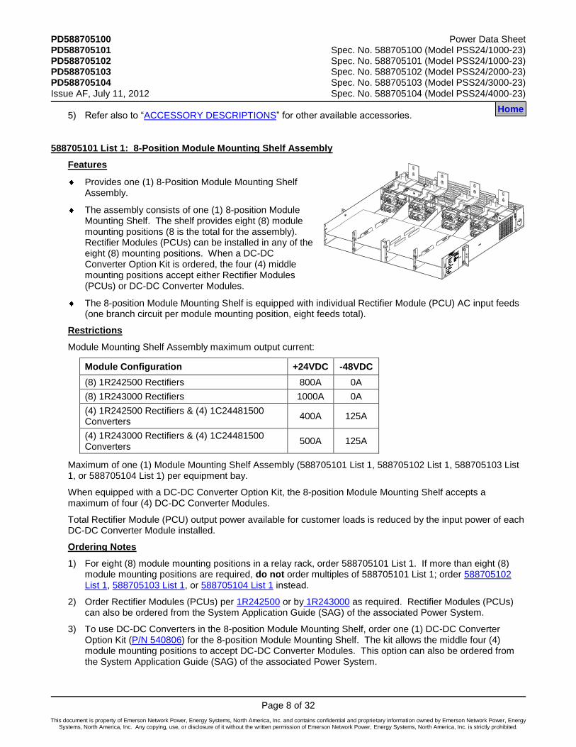
588705100 List 1: Field Expansion Kit (8-Position Module Mounting Shelf Assembly)
Features
Provides one (1) 8-Position Module Mounting Shelf Assembly, and components required for field installation in an existing NetSure Power System.
Expands capacity of a NetSure Power System equipped with a 588705101 List 1, 588705102 List 1, or 588705103 List 1.
The assembly consists of one (1) 8-position Module Mounting Shelf. The shelf provides eight (8) module mounting positions (8 is the total for the assembly). Rectifier Modules (PCUs) can be installed in any of the eight (8) mounting positions. Also provided is DC-DC Converter Option Kit (P/N 540806). This allows the four (4) middle mounting positions to accept either Rectifier Modules (PCUs) or DC-DC Converter Modules.
The 8-position Module Mounting Shelf is equipped with individual Rectifier Module (PCU) AC input feeds (one branch circuit per module mounting position, eight feeds total).
Restrictions
Module Mounting Shelf Assembly maximum output current:
Module Configuration +24VDC -48VDC
(8) 1R242500 Rectifiers 800A 0A
(8) 1R243000 Rectifiers 1000A 0A
(4) 1R242500 Rectifiers & (4) 1C24481500 Converters 400A 125A
(4) 1R243000 Rectifiers & (4) 1C24481500 Converters 500A 125A
For field installation only.
Cannot be used with a Spec No. 588705104 List 1 Assembly.
Maximum of one (1) Module Mounting Expansion Assembly (588705100 List 1) per equipment bay.
Total Rectifier Module (PCU) output power available for customer loads is reduced by the input power of each DC-DC Converter Module installed.
Ordering Notes
1) Order one (1) 588705100 List 1 per power system bay as required (see Restrictions above). Can also be ordered from the System Application Guide (SAG) of the associated Power System.
2) Order Rectifier Modules (PCUs) per 1R242500 or by 1R243000 as required. Rectifier Modules (PCUs) can also be ordered from the System Application Guide (SAG) of the associated Power System.
3) Order DC-DC Converter Modules per 1C24481500 as required. Converter Modules can also be ordered from the System Application Guide (SAG) of the associated Power System.
4) Order one (1) Module Mounting Position Blank Cover (P/N 540959) for each empty module mounting position in the assembly. Blank Covers can also be ordered from the System Application Guide (SAG) of the associated Power System.
Home
PD588705100 Power Data Sheet PD588705101 Spec. No. 588705100 (Model PSS24/1000-23) PD588705102 Spec. No. 588705101 (Model PSS24/1000-23) PD588705103 Spec. No. 588705102 (Model PSS24/2000-23) PD588705104 Spec. No. 588705103 (Model PSS24/3000-23) Issue AF, July 11, 2012 Spec. No. 588705104 (Model PSS24/4000-23)
Page 8 of 32
This document is property of Emerson Network Power, Energy Systems, North America, Inc. and contains confidential and proprietary information owned by Emerson Network Power, Energy Systems, North America, Inc. Any copying, use, or disclosure of it without the written permission of Emerson Network Power, Energy Systems, North America, Inc. is strictly prohibited.
5) Refer also to “ACCESSORY DESCRIPTIONS” for other available accessories.
588705101 List 1: 8-Position Module Mounting Shelf Assembly
Features
Provides one (1) 8-Position Module Mounting Shelf Assembly.
The assembly consists of one (1) 8-position Module Mounting Shelf. The shelf provides eight (8) module mounting positions (8 is the total for the assembly). Rectifier Modules (PCUs) can be installed in any of the eight (8) mounting positions. When a DC-DC Converter Option Kit is ordered, the four (4) middle mounting positions accept either Rectifier Modules (PCUs) or DC-DC Converter Modules.
The 8-position Module Mounting Shelf is equipped with individual Rectifier Module (PCU) AC input feeds (one branch circuit per module mounting position, eight feeds total).
Restrictions
Module Mounting Shelf Assembly maximum output current:
Module Configuration +24VDC -48VDC
(8) 1R242500 Rectifiers 800A 0A
(8) 1R243000 Rectifiers 1000A 0A
(4) 1R242500 Rectifiers & (4) 1C24481500 Converters
400A 125A
(4) 1R243000 Rectifiers & (4) 1C24481500 Converters
500A 125A
Maximum of one (1) Module Mounting Shelf Assembly (588705101 List 1, 588705102 List 1, 588705103 List 1, or 588705104 List 1) per equipment bay.
When equipped with a DC-DC Converter Option Kit, the 8-position Module Mounting Shelf accepts a maximum of four (4) DC-DC Converter Modules.
Total Rectifier Module (PCU) output power available for customer loads is reduced by the input power of each DC-DC Converter Module installed.
Ordering Notes
1) For eight (8) module mounting positions in a relay rack, order 588705101 List 1. If more than eight (8) module mounting positions are required, do not order multiples of 588705101 List 1; order 588705102 List 1, 588705103 List 1, or 588705104 List 1 instead.
2) Order Rectifier Modules (PCUs) per 1R242500 or by 1R243000 as required. Rectifier Modules (PCUs) can also be ordered from the System Application Guide (SAG) of the associated Power System.
3) To use DC-DC Converters in the 8-position Module Mounting Shelf, order one (1) DC-DC Converter Option Kit (P/N 540806) for the 8-position Module Mounting Shelf. The kit allows the middle four (4) module mounting positions to accept DC-DC Converter Modules. This option can also be ordered from the System Application Guide (SAG) of the associated Power System.
Home
Power Data Sheet PD588705100 Spec. No. 588705100 (Model PSS24/1000-23) PD588705101 Spec. No. 588705101 (Model PSS24/1000-23) PD588705102 Spec. No. 588705102 (Model PSS24/2000-23) PD588705103 Spec. No. 588705103 (Model PSS24/3000-23) PD588705104 Spec. No. 588705104 (Model PSS24/4000-23) Issue AF, July 11, 2012
Page 9 of 32
This document is property of Emerson Network Power, Energy Systems, North America, Inc. and contains confidential and proprietary information owned by Emerson Network Power, Energy Systems, North America, Inc. Any copying, use, or disclosure of it without the written permission of Emerson Network Power, Energy Systems, North America, Inc. is strictly prohibited.
4) Order DC-DC Converter Modules per 1C24481500 as required. Converter Modules can also be ordered from the System Application Guide (SAG) of the associated Power System.
5) Order one (1) Module Mounting Position Blank Cover (P/N 540959) for each empty module mounting position in the assembly. Blank Covers can also be ordered from the System Application Guide (SAG) of the associated Power System.
6) Refer also to “ACCESSORY DESCRIPTIONS” for other available accessories.
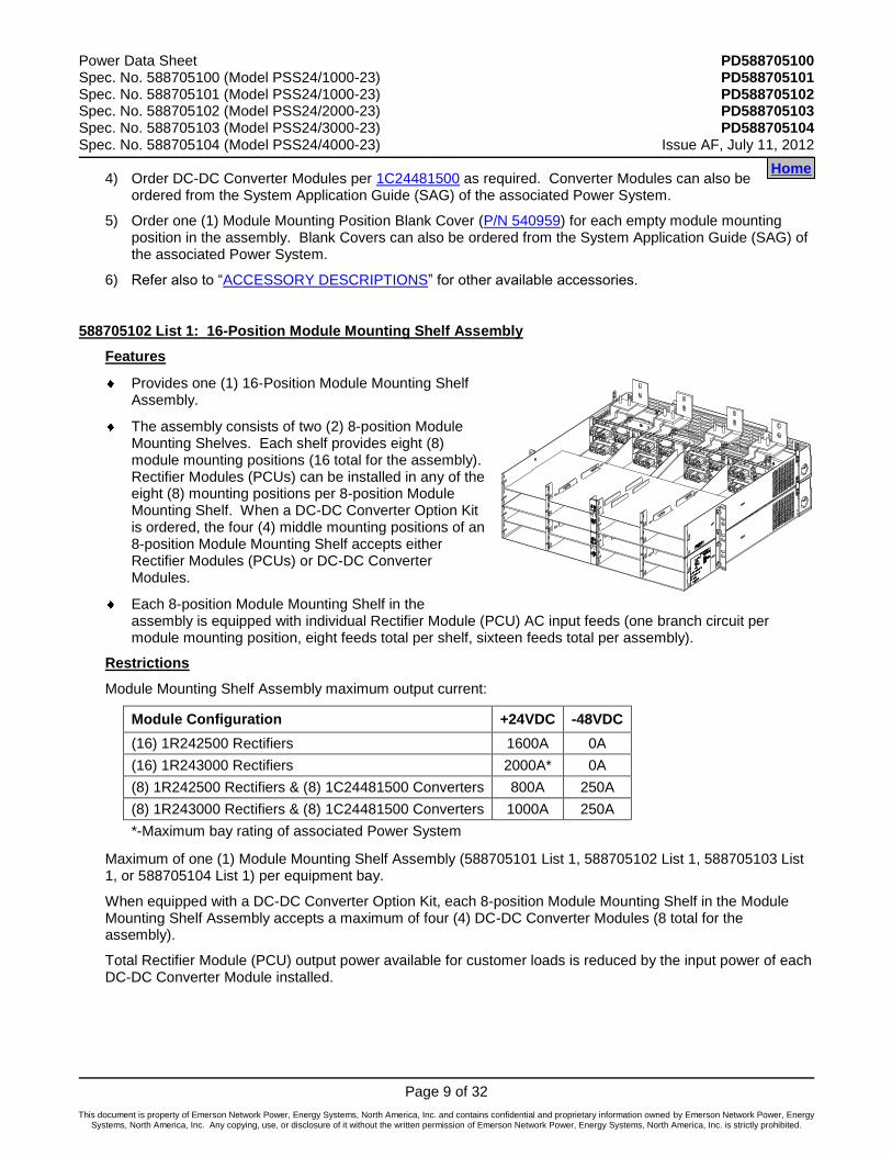
588705102 List 1: 16-Position Module Mounting Shelf Assembly
Features
Provides one (1) 16-Position Module Mounting Shelf Assembly.
The assembly consists of two (2) 8-position Module Mounting Shelves. Each shelf provides eight (8) module mounting positions (16 total for the assembly). Rectifier Modules (PCUs) can be installed in any of the eight (8) mounting positions per 8-position Module Mounting Shelf. When a DC-DC Converter Option Kit is ordered, the four (4) middle mounting positions of an 8-position Module Mounting Shelf accepts either Rectifier Modules (PCUs) or DC-DC Converter Modules.
Each 8-position Module Mounting Shelf in the assembly is equipped with individual Rectifier Module (PCU) AC input feeds (one branch circuit per module mounting position, eight feeds total per shelf, sixteen feeds total per assembly).
Restrictions
Module Mounting Shelf Assembly maximum output current:
Module Configuration +24VDC -48VDC
(16) 1R242500 Rectifiers 1600A 0A
(16) 1R243000 Rectifiers 2000A* 0A
(8) 1R242500 Rectifiers & (8) 1C24481500 Converters 800A 250A
(8) 1R243000 Rectifiers & (8) 1C24481500 Converters 1000A 250A
*-Maximum bay rating of associated Power System
Maximum of one (1) Module Mounting Shelf Assembly (588705101 List 1, 588705102 List 1, 588705103 List 1, or 588705104 List 1) per equipment bay.
When equipped with a DC-DC Converter Option Kit, each 8-position Module Mounting Shelf in the Module Mounting Shelf Assembly accepts a maximum of four (4) DC-DC Converter Modules (8 total for the assembly).
Total Rectifier Module (PCU) output power available for customer loads is reduced by the input power of each DC-DC Converter Module installed.
Home
PD588705100 Power Data Sheet PD588705101 Spec. No. 588705100 (Model PSS24/1000-23) PD588705102 Spec. No. 588705101 (Model PSS24/1000-23) PD588705103 Spec. No. 588705102 (Model PSS24/2000-23) PD588705104 Spec. No. 588705103 (Model PSS24/3000-23) Issue AF, July 11, 2012 Spec. No. 588705104 (Model PSS24/4000-23)
Page 10 of 32
This document is property of Emerson Network Power, Energy Systems, North America, Inc. and contains confidential and proprietary information owned by Emerson Network Power, Energy Systems, North America, Inc. Any copying, use, or disclosure of it without the written permission of Emerson Network Power, Energy Systems, North America, Inc. is strictly prohibited.
Ordering Notes
1) For sixteen (16) module mounting positions in a relay rack, order 588705102 List 1. If more than sixteen (16) module mounting positions are required, do not order multiples of 588705102 List 1; order 588705103 List 1 or 588705104 List 1 instead.
2) Order Rectifier Modules (PCUs) per 1R242500 or by 1R243000 as required. Rectifier Modules (PCUs) can also be ordered from the System Application Guide (SAG) of the associated Power System.
3) To use DC-DC Converters in any 8-position Module Mounting Shelf in this Module Mounting Shelf Assembly, order one (1) DC-DC Converter Option Kit (P/N 540806) for each 8-position Module Mounting Shelf in which Converters are required. Each kit allows the middle four (4) module mounting positions in one 8-position Module Mounting Shelf to accept DC-DC Converter Modules. When more than one kit is ordered, kits will be factory installed starting in the bottom 8-position Module Mounting Shelf in the Module Mounting Shelf Assembly and working up. This option can also be ordered from the System Application Guide (SAG) of the associated Power System.
4) Order DC-DC Converter Modules per 1C24481500 as required. Converter Modules can also be ordered from the System Application Guide (SAG) of the associated Power System.
5) Order one (1) Module Mounting Position Blank Cover (P/N 540959) for each empty module mounting position in the assembly. Blank Covers can also be ordered from the System Application Guide (SAG) of the associated Power System.
6) Refer also to “ACCESSORY DESCRIPTIONS” for other available accessories.
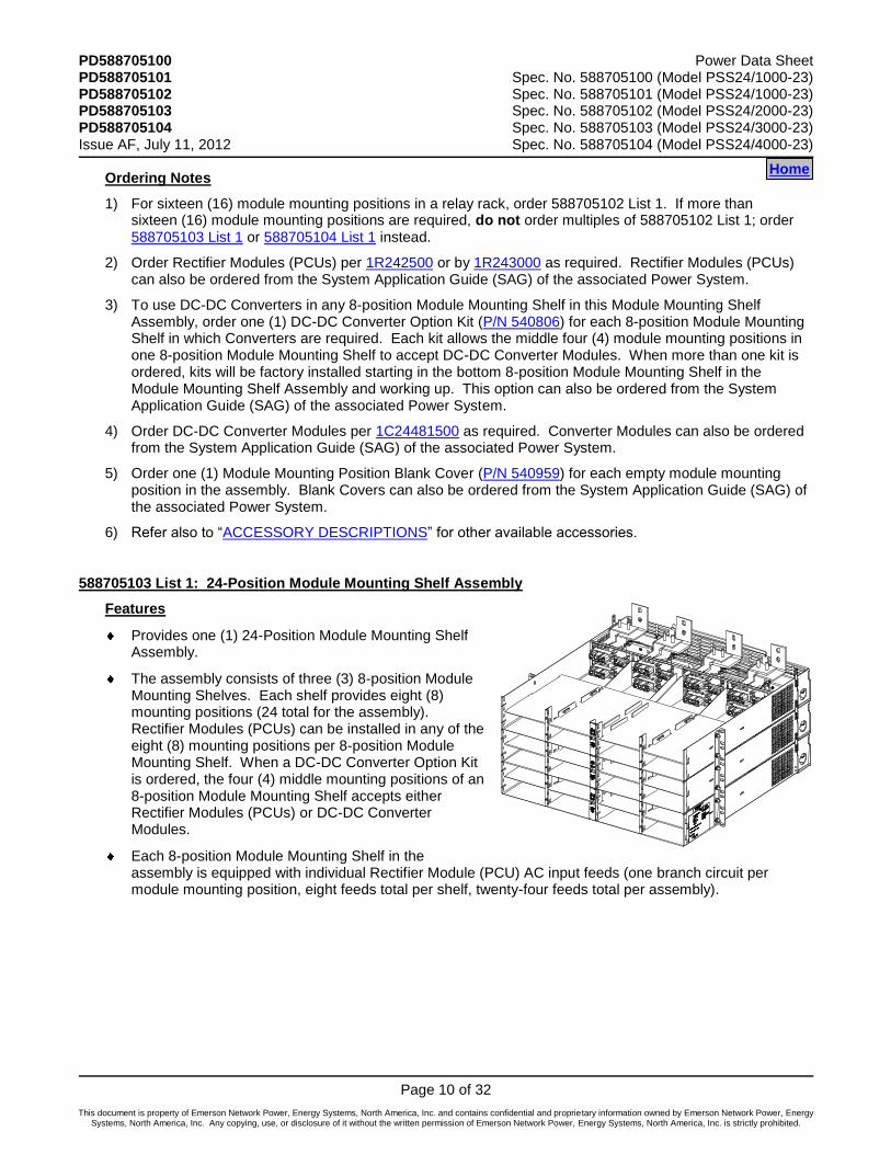
588705103 List 1: 24-Position Module Mounting Shelf Assembly
Features
Provides one (1) 24-Position Module Mounting Shelf Assembly.
The assembly consists of three (3) 8-position Module Mounting Shelves. Each shelf provides eight (8) mounting positions (24 total for the assembly). Rectifier Modules (PCUs) can be installed in any of the eight (8) mounting positions per 8-position Module Mounting Shelf. When a DC-DC Converter Option Kit is ordered, the four (4) middle mounting positions of an 8-position Module Mounting Shelf accepts either Rectifier Modules (PCUs) or DC-DC Converter Modules.
Each 8-position Module Mounting Shelf in the assembly is equipped with individual Rectifier Module (PCU) AC input feeds (one branch circuit per module mounting position, eight feeds total per shelf, twenty-four feeds total per assembly).
Home
Power Data Sheet PD588705100 Spec. No. 588705100 (Model PSS24/1000-23) PD588705101 Spec. No. 588705101 (Model PSS24/1000-23) PD588705102 Spec. No. 588705102 (Model PSS24/2000-23) PD588705103 Spec. No. 588705103 (Model PSS24/3000-23) PD588705104 Spec. No. 588705104 (Model PSS24/4000-23) Issue AF, July 11, 2012
Page 11 of 32
This document is property of Emerson Network Power, Energy Systems, North America, Inc. and contains confidential and proprietary information owned by Emerson Network Power, Energy Systems, North America, Inc. Any copying, use, or disclosure of it without the written permission of Emerson Network Power, Energy Systems, North America, Inc. is strictly prohibited.
Restrictions
Module Mounting Shelf Assembly maximum output current:
Module Configuration +24VDC -48VDC
(20) 1R242500 Rectifiers & (4) 1C24481500 Converters 2000A* 125A
(16) 1R243000 Rectifiers & (8) 1C24481500 Converters 2000A* 250A
(12) 1R242500 Rectifiers & (12) 1C24481500 Converters 1200A 375A
(12) 1R243000 Rectifiers & (12) 1C24481500 Converters 1500A 375A
* - Maximum bay rating of associated Power System
Maximum of one (1) Module Mounting Shelf Assembly (588705101 List 1, 588705102 List 1, 588705103 List 1, or 588705104 List 1) per equipment bay.
When equipped with a DC-DC Converter Option Kit, each 8-position Module Mounting Shelf in the Module Mounting Shelf Assembly accepts a maximum of four (4) DC-DC Converter Modules (12 total for the assembly).
Total Rectifier Module (PCU) output power available for customer loads is reduced by the input power of each DC-DC Converter Module installed.
Ordering Notes
1) For twenty-four (24) module mounting positions in a relay rack, order 588705103 List 1. If more than twenty-four (24) module mounting positions are required, do not order multiples of 588705103 List 1; order 588705104 List 1 instead.
2) Order Rectifier Modules (PCUs) per 1R242500 or by 1R243000 as required. Rectifier Modules (PCUs) can also be ordered from the System Application Guide (SAG) of the associated Power System.
3) To use DC-DC Converters in any 8-position Module Mounting Shelf in this Module Mounting Shelf Assembly, order one (1) DC-DC Converter Option Kit (P/N 540806) for each 8-position Module Mounting Shelf in which Converters are required. Each kit allows the middle four (4) module mounting positions in one 8-position Module Mounting Shelf to accept DC-DC Converter Modules. When more than one kit is ordered, kits will be factory installed starting in the bottom 8-position Module Mounting Shelf in the Module Mounting Shelf Assembly and working up. This option can also be ordered from the System Application Guide (SAG) of the associated Power System.
4) Order DC-DC Converter Modules per 1C24481500 as required. Converter Modules can also be ordered from the System Application Guide (SAG) of the associated Power System.
5) Order one (1) Module Mounting Position Blank Cover (P/N 540959) for each empty module mounting position in the assembly. Blank Covers can also be ordered from the System Application Guide (SAG) of the associated Power System.
6) Refer also to “ACCESSORY DESCRIPTIONS” for other available accessories.
Home
PD588705100 Power Data Sheet PD588705101 Spec. No. 588705100 (Model PSS24/1000-23) PD588705102 Spec. No. 588705101 (Model PSS24/1000-23) PD588705103 Spec. No. 588705102 (Model PSS24/2000-23) PD588705104 Spec. No. 588705103 (Model PSS24/3000-23) Issue AF, July 11, 2012 Spec. No. 588705104 (Model PSS24/4000-23)
Page 12 of 32
This document is property of Emerson Network Power, Energy Systems, North America, Inc. and contains confidential and proprietary information owned by Emerson Network Power, Energy Systems, North America, Inc. Any copying, use, or disclosure of it without the written permission of Emerson Network Power, Energy Systems, North America, Inc. is strictly prohibited.
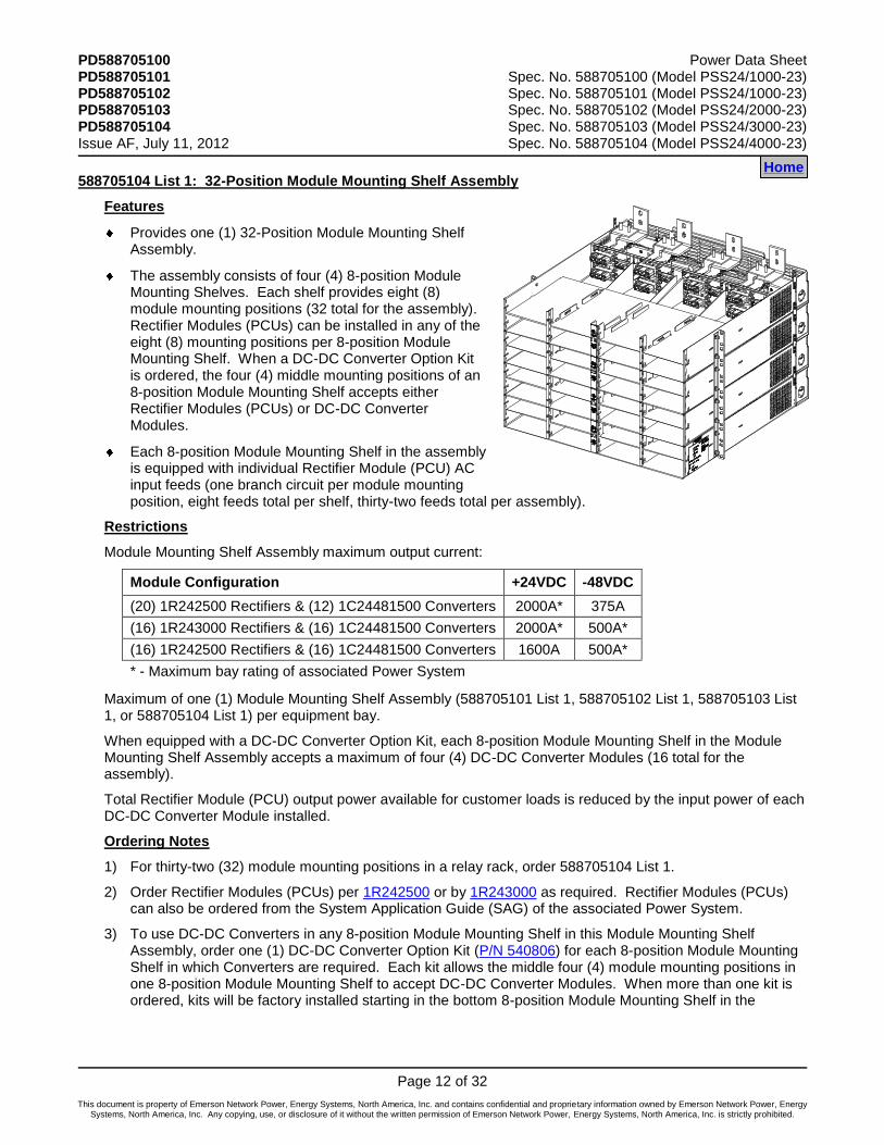
588705104 List 1: 32-Position Module Mounting Shelf Assembly
Features
Provides one (1) 32-Position Module Mounting Shelf Assembly.
The assembly consists of four (4) 8-position Module Mounting Shelves. Each shelf provides eight (8) module mounting positions (32 total for the assembly). Rectifier Modules (PCUs) can be installed in any of the eight (8) mounting positions per 8-position Module Mounting Shelf. When a DC-DC Converter Option Kit is ordered, the four (4) middle mounting positions of an 8-position Module Mounting Shelf accepts either Rectifier Modules (PCUs) or DC-DC Converter Modules.
Each 8-position Module Mounting Shelf in the assembly is equipped with individual Rectifier Module (PCU) AC input feeds (one branch circuit per module mounting position, eight feeds total per shelf, thirty-two feeds total per assembly).
Restrictions
Module Mounting Shelf Assembly maximum output current:
Module Configuration +24VDC -48VDC
(20) 1R242500 Rectifiers & (12) 1C24481500 Converters 2000A* 375A
(16) 1R243000 Rectifiers & (16) 1C24481500 Converters 2000A* 500A*
(16) 1R242500 Rectifiers & (16) 1C24481500 Converters 1600A 500A*
* - Maximum bay rating of associated Power System
Maximum of one (1) Module Mounting Shelf Assembly (588705101 List 1, 588705102 List 1, 588705103 List 1, or 588705104 List 1) per equipment bay.
When equipped with a DC-DC Converter Option Kit, each 8-position Module Mounting Shelf in the Module Mounting Shelf Assembly accepts a maximum of four (4) DC-DC Converter Modules (16 total for the assembly).
Total Rectifier Module (PCU) output power available for customer loads is reduced by the input power of each DC-DC Converter Module installed.
Ordering Notes
1) For thirty-two (32) module mounting positions in a relay rack, order 588705104 List 1.
2) Order Rectifier Modules (PCUs) per 1R242500 or by 1R243000 as required. Rectifier Modules (PCUs) can also be ordered from the System Application Guide (SAG) of the associated Power System.
3) To use DC-DC Converters in any 8-position Module Mounting Shelf in this Module Mounting Shelf Assembly, order one (1) DC-DC Converter Option Kit (P/N 540806) for each 8-position Module Mounting Shelf in which Converters are required. Each kit allows the middle four (4) module mounting positions in one 8-position Module Mounting Shelf to accept DC-DC Converter Modules. When more than one kit is ordered, kits will be factory installed starting in the bottom 8-position Module Mounting Shelf in the
Home Home

Power Data Sheet PD588705100 Spec. No. 588705100 (Model PSS24/1000-23) PD588705101 Spec. No. 588705101 (Model PSS24/1000-23) PD588705102 Spec. No. 588705102 (Model PSS24/2000-23) PD588705103 Spec. No. 588705103 (Model PSS24/3000-23) PD588705104 Spec. No. 588705104 (Model PSS24/4000-23) Issue AF, July 11, 2012
Page 13 of 32
This document is property of Emerson Network Power, Energy Systems, North America, Inc. and contains confidential and proprietary information owned by Emerson Network Power, Energy Systems, North America, Inc. Any copying, use, or disclosure of it without the written permission of Emerson Network Power, Energy Systems, North America, Inc. is strictly prohibited.
Module Mounting Shelf Assembly and working up. This option can also be ordered from the System Application Guide (SAG) of the associated Power System.
4) Order DC-DC Converter Modules per 1C24481500 as required. Converter Modules can also be ordered from the System Application Guide (SAG) of the associated Power System.
5) Order one (1) Module Mounting Position Blank Cover (P/N 540959) for each empty module mounting position in the assembly. Blank Covers can also be ordered from the System Application Guide (SAG) of the associated Power System.
6) Refer also to “ACCESSORY DESCRIPTIONS” for other available accessories.
Home
PD588705100 Power Data Sheet PD588705101 Spec. No. 588705100 (Model PSS24/1000-23) PD588705102 Spec. No. 588705101 (Model PSS24/1000-23) PD588705103 Spec. No. 588705102 (Model PSS24/2000-23) PD588705104 Spec. No. 588705103 (Model PSS24/3000-23) Issue AF, July 11, 2012 Spec. No. 588705104 (Model PSS24/4000-23)
Page 14 of 32
This document is property of Emerson Network Power, Energy Systems, North America, Inc. and contains confidential and proprietary information owned by Emerson Network Power, Energy Systems, North America, Inc. Any copying, use, or disclosure of it without the written permission of Emerson Network Power, Energy Systems, North America, Inc. is strictly prohibited.
ACCESSORY DESCRIPTIONS
Rectifier and Converter Modules
Part No. 1R242500: 2500W Rectifier Module
Features
Provides one (1) Model R24-2500 (+24V, 104.2A, 2500W), Rectifier Module (PCU).
Ordering Notes
1) Order as required.
Part No. 1R243000: 3000W, Rectifier Module
Features
Provides one (1) Model R24-3000, (+24V, 125.0A, 3000W). High Efficiency Rectifier Module.
Restrictions
Refer to the power systems SAG (System Application Guide) for any compatibility issues in using this rectifier in power systems manufactured before this rectifier was available.
Ordering Notes
1) Order as required for any List 1 Mounting Assembly in this document.
Part No. 1C24481500: 1500W Converter Module
Features
Provides one (1) Model C24/48-1500 (-48V, 31A, 1500W), DC-DC Converter Module.
Restrictions
Requires kit P/N 540806. Note that this kit is furnished in 588705100 List 1 and does not need to be ordered separately.
Ordering Notes
1) Order as required. Each 8-position Module Mounting Shelf in a Module Mounting Shelf Assembly holds up to four (4) DC-DC Converter Modules when equipped with a DC-DC Converter Option Kit.
Home Home Home

Power Data Sheet PD588705100 Spec. No. 588705100 (Model PSS24/1000-23) PD588705101 Spec. No. 588705101 (Model PSS24/1000-23) PD588705102 Spec. No. 588705102 (Model PSS24/2000-23) PD588705103 Spec. No. 588705103 (Model PSS24/3000-23) PD588705104 Spec. No. 588705104 (Model PSS24/4000-23) Issue AF, July 11, 2012
Page 15 of 32
This document is property of Emerson Network Power, Energy Systems, North America, Inc. and contains confidential and proprietary information owned by Emerson Network Power, Energy Systems, North America, Inc. Any copying, use, or disclosure of it without the written permission of Emerson Network Power, Energy Systems, North America, Inc. is strictly prohibited.
Module Mounting Position Blank Cover Panel (P/N 540959)
Features
Covers one (1) unused module mounting position.
Ordering Notes
1) Order one (1) blank cover panel, P/N 540959, for each empty module mounting position in the system. Blank Covers can also be ordered from the System Application Guide (SAG) of the associated Power System.
DC-DC Converter Option Interface Component Kit (P/N 540806)
Features
Provides components to add DC-DC Converter capability to one (1) 8-position Module Mounting Shelf. When installed, the four middle mounting positions in an 8-position Module Mounting Shelf accepts DC-DC Converters or Rectifier Modules (PCUs).
Includes cables for connection of converter output to a dual voltage bus distribution panel assembly in a Distribution Cabinet of an associated Power System.
Note that this option is furnished in 588705100 List 1.
Restrictions
MUST be factory installed only.
Total rectifier output power available for customer loads is reduced by the input power of each DC-DC Converter Module installed.
Ordering Notes
1) Order one (1) kit, P/N 540806, for each 8-position Module Mounting Shelf in which DC-DC Converters are required. Note that some Module Mounting Shelf Assemblies consist of multiple 8-position Module Mounting Shelves. The kit permits the middle four (4) positions in an 8-position Module Mounting Shelf to accept DC-DC Converter Modules or Rectifier Modules (PCUs). The kit is factory installed within the 8-position Module Mounting Shelf. Multiple kits will be installed starting with bottom 8-position Module Mounting Shelf in the Module Mounting Shelf Assembly and working up. Kit can also be ordered from the System Application Guide (SAG) of the associated Power System.
2) Order up to four (4) converter modules for each kit ordered.
Home

PD588705100 Power Data Sheet PD588705101 Spec. No. 588705100 (Model PSS24/1000-23) PD588705102 Spec. No. 588705101 (Model PSS24/1000-23) PD588705103 Spec. No. 588705102 (Model PSS24/2000-23) PD588705104 Spec. No. 588705103 (Model PSS24/3000-23) Issue AF, July 11, 2012 Spec. No. 588705104 (Model PSS24/4000-23)
Page 16 of 32
This document is property of Emerson Network Power, Energy Systems, North America, Inc. and contains confidential and proprietary information owned by Emerson Network Power, Energy Systems, North America, Inc. Any copying, use, or disclosure of it without the written permission of Emerson Network Power, Energy Systems, North America, Inc. is strictly prohibited.
Battery Charge Temperature Compensation Probe for Single Probe Digital Compensation
Features
This system can be used with a Battery Charge Temperature Compensation Probe. This probe must be mounted near the battery to sense battery ambient temperature. The probe connects to and allows the MCA of the associated Power System to automatically increase or decrease the output voltage of the system to maintain battery float current as battery ambient temperature decreases or increases, respectively. Battery life can be extended when an optimum charge voltage to the battery with respect to temperature is maintained. Two probes are available. Part No. 107021 has a 25-foot long cord. Part No. 106824 has a 100 foot-long cord. See Overall Dimensions, Digital Battery Charge Temperature Compensation Probe (P/N 107021 and 106824) under PHYSICAL SIZE INFORMATION for a dimensional drawing.
Allows Rectifier Module Battery Charge Temperature Compensation.
Temperature Curve: Refer to Figure 1.
Ordering Notes
1) Order one Battery Charge Temperature Compensation Probe per Power System, as required. Can also be ordered from the System Application Guide (SAG) of the associated Power System.
SLOPE
Adjustable from 0.0 V / °C
to 0.1 V / °C
MIN W/T
Adjustable from
Float to 23V
MAX W/T
Adjustable from
Float to 29.25V max.*
+25°C
(+77°F)
FLOAT
Determines Float Mode
Output Voltage at 25°C.
Adjustable from 23.5V
to 29.0V max.*
TemperatureIncreasingDecreasing
Volta
ge
Decre
asin
gIn
cre
asin
g
* Maximum setting is automatically
limited to 0.5 volt less than HVSD setting.
Figure 1 Typical Float Charge Thermal Characteristics
Using Optional Battery Charge Digital Temperature Compensation Probe (Indicated parameters are user-adjustable via the associated MCA.)
Home

Power Data Sheet PD588705100 Spec. No. 588705100 (Model PSS24/1000-23) PD588705101 Spec. No. 588705101 (Model PSS24/1000-23) PD588705102 Spec. No. 588705102 (Model PSS24/2000-23) PD588705103 Spec. No. 588705103 (Model PSS24/3000-23) PD588705104 Spec. No. 588705104 (Model PSS24/4000-23) Issue AF, July 11, 2012
Page 17 of 32
This document is property of Emerson Network Power, Energy Systems, North America, Inc. and contains confidential and proprietary information owned by Emerson Network Power, Energy Systems, North America, Inc. Any copying, use, or disclosure of it without the written permission of Emerson Network Power, Energy Systems, North America, Inc. is strictly prohibited.
521211
521228
Battery Charge Temperature Compensation Probe Concentrator for Multiple Probe Use (TXM)
Battery Temperature Probe Concentrator Kit (P/N 524570)
Features
The Battery Temperature Probe Concentrator (TXM) expands battery temperature monitoring capabilities by providing a means of monitoring up to eight (8) analog battery temperature probes. The TXM provides a digital output for connection to the associated Power System’s MCA’s battery temperature probe connector. The MCA can be programmed to compensate for the hottest probe reading, the average temperature of all connected probes, or the probe connected to the lowest numbered connector. The kit includes one TXM (P/N 521211) and one 25 ft. interface cable (P/N 521228) for connecting the TXM to the MCA.
Restrictions
Requires P/N 521262 analog probes. Cannot be used with digital probes (P/Ns 106824 and 107021).
Ordering Notes
1) Order one Battery Charge Temperature Compensation Probe Concentrator Kit (P/N 524570) per power system and up to eight (8) P/N 521262 probes, as required. Can also be ordered from the System Application Guide (SAG) of the associated Power System.
2) Order extension cable P/N 514153 as required. Can also be ordered from the System Application Guide (SAG) of the associated Power System.
Analog Battery Temperature Probe (P/N 521262)
Features
An analog probe designed to sense internal battery temperature. Mounts on the negative terminal of the battery; mounting hole clears 5/16” hardware. Includes 15 ft. cable with connector. See Overall Dimensions, Analog Battery Temperature Probe (P/N 521262) under PHYSICAL SIZE INFORMATION for a dimensional drawing.
Ordering Notes
1) See above Ordering Notes.
TXM Extension Cable (P/N 514153)
Features
25 ft. long cable. Can be used between a P/N 521262 Analog Battery Temperature Probe and the TXM; or to extend a P/N 521228 interface cable between the TXM and MCA.
Ordering Notes
1) See above Ordering Notes.
Home
514153
PD588705100 Power Data Sheet PD588705101 Spec. No. 588705100 (Model PSS24/1000-23) PD588705102 Spec. No. 588705101 (Model PSS24/1000-23) PD588705103 Spec. No. 588705102 (Model PSS24/2000-23) PD588705104 Spec. No. 588705103 (Model PSS24/3000-23) Issue AF, July 11, 2012 Spec. No. 588705104 (Model PSS24/4000-23)
Page 18 of 32
This document is property of Emerson Network Power, Energy Systems, North America, Inc. and contains confidential and proprietary information owned by Emerson Network Power, Energy Systems, North America, Inc. Any copying, use, or disclosure of it without the written permission of Emerson Network Power, Energy Systems, North America, Inc. is strictly prohibited.
Replacement Cables
Ordering Notes
1) Refer to the System Application Guide (SAG) of the associated Power System for part numbers.
Replacement Components
Ordering Notes
1) Rectifier Module (PCU): Order via 1R242500 (2500W), 1R243000 (3000W), or the Power System documentation.
2) Rectifier Module Fan: Part No. 32010156 (2 required per Rectifier Module).
3) DC-DC Converter Module: Order via 1C24481500 or the Power System documentation.
4) DC-DC Converter Module Fan: Part No. 534520 (2 required per Converter Module).
Home

Power Data Sheet PD588705100 Spec. No. 588705100 (Model PSS24/1000-23) PD588705101 Spec. No. 588705101 (Model PSS24/1000-23) PD588705102 Spec. No. 588705102 (Model PSS24/2000-23) PD588705103 Spec. No. 588705103 (Model PSS24/3000-23) PD588705104 Spec. No. 588705104 (Model PSS24/4000-23) Issue AF, July 11, 2012
Page 19 of 32
This document is property of Emerson Network Power, Energy Systems, North America, Inc. and contains confidential and proprietary information owned by Emerson Network Power, Energy Systems, North America, Inc. Any copying, use, or disclosure of it without the written permission of Emerson Network Power, Energy Systems, North America, Inc. is strictly prohibited.
Wiring Notes
Refer also to the next section, Wiring Illustrations.
AC Input Branch Circuit Protection and Wire Size Selection
Features
Each 8-position Module Mounting Shelf in a Module Mounting Shelf Assembly contains rear mounted AC input terminal blocks and provides individual feeds to each Rectifier Module mounting position.
Restrictions
AC input terminal blocks are “tubular contact - screw compression” type and accept a wire size in the range of 10 to 24 AWG.
Ordering Notes
1) Refer to the following table.
THWN - 90°C Wire - Individual Feed Four Rectifiers (8 Current and 1 Ground Wire) per Conduit
Input Voltage
Input Current
Overcurrent Protection
(1)
30°C and 40°C Ambient Temperatures
(2)
Wire AWG
(2) (3)
Conduit Size (in.)
208 14 20A 12 1/2
240 12 15A 14 1/2
1 The AC input branch circuit protective device should be of the time-delay or high inrush type.
2 Wire sizes based on recommendations of the American National Standards Institute (ANSI) approved National Fire Protection Association's (NFPA) National Electrical Code (NEC). Table 310-16 for copper wire at 90°C conductor temperature; operating in
ambients of 30 C and 40 C was used. For other operating ambient temperatures, refer to the National Electrical Code. For operation in countries where the NEC is not recognized, follow applicable codes.
3 Equipment grounding conductors must be provided with the AC
input conductors supplied to the shelf. Frame ground terminals must be connected to earth ground, not power system neutral. Equipment grounding conductor size based on recommendations of the NEC Table 250-122 for copper wire. If aluminum or copper clad aluminum grounding conductor is used, refer to Table 250-122 for increased conductor size. For operation in countries where the NEC is not recognized, follow applicable codes.
Home
PD588705100 Power Data Sheet PD588705101 Spec. No. 588705100 (Model PSS24/1000-23) PD588705102 Spec. No. 588705101 (Model PSS24/1000-23) PD588705103 Spec. No. 588705102 (Model PSS24/2000-23) PD588705104 Spec. No. 588705103 (Model PSS24/3000-23) Issue AF, July 11, 2012 Spec. No. 588705104 (Model PSS24/4000-23)
Page 20 of 32
This document is property of Emerson Network Power, Energy Systems, North America, Inc. and contains confidential and proprietary information owned by Emerson Network Power, Energy Systems, North America, Inc. Any copying, use, or disclosure of it without the written permission of Emerson Network Power, Energy Systems, North America, Inc. is strictly prohibited.
Shelf Frame Ground Wire Size Selection
Features
Two 10-32 X 3/4" frame ground studs with hardware are provided on the rear of each 8-position Module Mounting Shelf.
Restrictions
Recommended frame ground wire size is the same size as the AC input branch circuit wiring.
For relay rack grounding requirements, refer to the NEC, applicable local codes, and your specific site requirements.
DC Output Connections: +24VDC System Output
Features
Busbars are provided within each Module Mounting Shelf Assembly for factory connection into a NetSure Power System.
Ordering Notes
1) No wire size or lug recommendations are provided here. Shelf +24VDC output is connected via busbars to the distribution section of a NetSure Power System.
DC Output Connections: –48VDC Subsystem Output
Features
Busbars are provided within each Module Mounting Shelf Assembly for factory connection into a NetSure Power System.
Ordering Notes
1) No wire size or lug recommendations are provided here. Shelf –48VDC output is connected via factory-installed cabling to the distribution section of a NetSure Power System.
External Alarms Wire Size Selection
Ordering Notes
1) No wire size recommendations are provided here. Shelf external alarms are provided via the MCA of an associated NetSure Power System.
Home
Power Data Sheet PD588705100 Spec. No. 588705100 (Model PSS24/1000-23) PD588705101 Spec. No. 588705101 (Model PSS24/1000-23) PD588705102 Spec. No. 588705102 (Model PSS24/2000-23) PD588705103 Spec. No. 588705103 (Model PSS24/3000-23) PD588705104 Spec. No. 588705104 (Model PSS24/4000-23) Issue AF, July 11, 2012
Page 21 of 32
This document is property of Emerson Network Power, Energy Systems, North America, Inc. and contains confidential and proprietary information owned by Emerson Network Power, Energy Systems, North America, Inc. Any copying, use, or disclosure of it without the written permission of Emerson Network Power, Energy Systems, North America, Inc. is strictly prohibited.
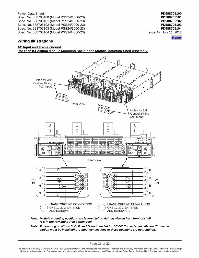
Wiring Illustrations
AC Input and Frame Ground (for each 8-Position Module Mounting Shelf in the Module Mounting Shelf Assembly)
Note: Module mounting positions are lettered left to right as viewed from front of shelf, A-D in top row and E-H in bottom row.
Rear View
Holes for 3/4"Conduit Fitting(AC Input)
Holes for 3/4"Conduit Fitting
(AC Input)
ONE 10-32 X 3/4" STUD AND HARDWARE
FRAME GROUND CONNECTION
ONE 10-32 X 3/4" STUD AND HARDWARE
1
2
1
2
ACIN
C1
2
D
H
1
2G
1
2
1
2
ACIN
B1
2
A
E
1
2F
FRAME GROUND CONNECTION
TB1TB2TB3TB4
Rear View
Note: If mounting positions B, C, F, and G are intended for DC-DC Converter installation (Converter Option must be installed), AC input connections to these positions are not required.
Home
PD588705100 Power Data Sheet PD588705101 Spec. No. 588705100 (Model PSS24/1000-23) PD588705102 Spec. No. 588705101 (Model PSS24/1000-23) PD588705103 Spec. No. 588705102 (Model PSS24/2000-23) PD588705104 Spec. No. 588705103 (Model PSS24/3000-23) Issue AF, July 11, 2012 Spec. No. 588705104 (Model PSS24/4000-23)
Page 22 of 32
This document is property of Emerson Network Power, Energy Systems, North America, Inc. and contains confidential and proprietary information owned by Emerson Network Power, Energy Systems, North America, Inc. Any copying, use, or disclosure of it without the written permission of Emerson Network Power, Energy Systems, North America, Inc. is strictly prohibited.
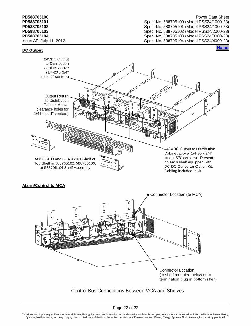
DC Output
588705100 and 588705101 Shelf orTop Shelf in 588705102, 588705103,
or 588705104 Shelf Assembly
Output Returnto Distribution
Cabinet Above(clearance holes for
1/4 bolts, 1" centers)
+24VDC Outputto Distribution
Cabinet Above(1/4-20 x 3/4"
studs, 1" centers)
–48VDC Output to DistributionCabinet above (1/4-20 x 3/4" studs, 5/8" centers). Present on each shelf equipped withDC-DC Converter Option Kit. Cabling included in kit.
Alarm/Control to MCA
Connector Location (to MCA)
Connector Location(to shelf mounted below or totermination plug in bottom shelf)
Control Bus Connections Between MCA and Shelves
Home
Power Data Sheet PD588705100 Spec. No. 588705100 (Model PSS24/1000-23) PD588705101 Spec. No. 588705101 (Model PSS24/1000-23) PD588705102 Spec. No. 588705102 (Model PSS24/2000-23) PD588705103 Spec. No. 588705103 (Model PSS24/3000-23) PD588705104 Spec. No. 588705104 (Model PSS24/4000-23) Issue AF, July 11, 2012
Page 23 of 32
This document is property of Emerson Network Power, Energy Systems, North America, Inc. and contains confidential and proprietary information owned by Emerson Network Power, Energy Systems, North America, Inc. Any copying, use, or disclosure of it without the written permission of Emerson Network Power, Energy Systems, North America, Inc. is strictly prohibited.
SPECIFICATIONS
Note: Refer to the separate System Application Guide (SAG) of the associated Power System for the following:
MCA specifications and factory default settings.
All external alarms.
All external controls.
Local status and alarm indicators other than those provided on the Rectifier Modules (PCUs) and DC-DC Converter Modules.
1. RECTIFIER SPECIFICATIONS
Refer to the separate Rectifier Instruction Document (UM1R243000).
2. DC-DC CONVERTER SPECIFICATIONS
Refer to the separate Converter Instruction Document (UM1C24481500).
3. MODULE MOUNTING SHELF SPECIFICATIONS
3.1 Environmental Ratings
3.1.1 Operating Ambient Temperature Range: -40°C to +40°C (-40°F to +104°F)
3.1.2 Storage Ambient Temperature Range: -40°C to +85°C (-40°F to +185°F).
3.1.3 Humidity: Capable of operating in an ambient relative humidity range of 0% to 95%, non-condensing.
3.1.4 Altitude: Capable of operating in an altitude range of -200 feet to 10,000 feet. The maximum operating ambient temperature should be de-rated by 3°C per 1000 feet above 5000 feet.
3.1.5 Ventilation Requirements:
(A) Ventilation: A Module Mounting Shelf must be mounted so ventilating openings are not blocked and temperature of the air entering the cabinet does not exceed the Operating Ambient Temperature Range stated above.
(B) Stacking Considerations: This system is designed for front to back ventilation to facilitate stacking of Module Mounting Shelves, one above the other, in a relay rack. There is no spacing requirement between stacked Module Mounting Shelves of a single system.
3.1.6 Audible Noise (System): The audible noise at any point two feet from any vertical surface of a Module Mounting Shelf (with Rectifier Modules installed and fans operating) does not exceed the following limits. The audible noise was measured with the fan control circuit enabled. A Sound Level Meter conforming to ANSI S1.4 was used.
(A) For One Rectifier Module:
(1) 50dB-A maximum at less than 32°C ambient, half load or less.
(2) 60dB-A maximum at less than 32°C ambient, full load.
(3) 70dB-A maximum at greater than 32°C ambient, full load.
(B) For Eight Rectifier Modules:
(1) 61dB-A maximum at less than 32°C ambient, half load or less.
(2) 71dB-A maximum at less than 32°C ambient, full load.
(3) 81dB-A maximum at greater than 32°C ambient, full load.
Home
PD588705100 Power Data Sheet PD588705101 Spec. No. 588705100 (Model PSS24/1000-23) PD588705102 Spec. No. 588705101 (Model PSS24/1000-23) PD588705103 Spec. No. 588705102 (Model PSS24/2000-23) PD588705104 Spec. No. 588705103 (Model PSS24/3000-23) Issue AF, July 11, 2012 Spec. No. 588705104 (Model PSS24/4000-23)
Page 24 of 32
This document is property of Emerson Network Power, Energy Systems, North America, Inc. and contains confidential and proprietary information owned by Emerson Network Power, Energy Systems, North America, Inc. Any copying, use, or disclosure of it without the written permission of Emerson Network Power, Energy Systems, North America, Inc. is strictly prohibited.
3.1.7 Mounting: The Module Mounting Shelf Assemblies are designed for mounting in a 23 inch wide relay rack with 1 inch or 1 3/4 inch multiple drilling.
3.2 Compliance Information
3.2.1 Safety Compliance: This unit meets the requirements of UL 60950-1, Standard for Information Technology Equipment, and is UL Recognized as a power supply for use in Telephone, Electronic Data Processing or Information Processing Equipment. This unit meets the requirements of CAN/CSA 22.2, No. 60950-00 and is tested and Certified by UL ("c UR") as a Component Type Power Supply.
3.2.2 NEBS Compliance: Compliance verified by a Nationally Recognized Testing Laboratory (NRTL) per GR-1089-CORE and GR-63-CORE. Contact Emerson Network Power for NEBS compliance reports.
In order to remain compliant during a fan failure condition, the backup battery connection must be utilized to provide sufficient power to the loads for up to eight (8) hours when the system is operated at greater than 50% output power. If no backup battery connection is used, the system must operate with a redundant module installed.
Home
Power Data Sheet PD588705100 Spec. No. 588705100 (Model PSS24/1000-23) PD588705101 Spec. No. 588705101 (Model PSS24/1000-23) PD588705102 Spec. No. 588705102 (Model PSS24/2000-23) PD588705103 Spec. No. 588705103 (Model PSS24/3000-23) PD588705104 Spec. No. 588705104 (Model PSS24/4000-23) Issue AF, July 11, 2012
Page 25 of 32
This document is property of Emerson Network Power, Energy Systems, North America, Inc. and contains confidential and proprietary information owned by Emerson Network Power, Energy Systems, North America, Inc. Any copying, use, or disclosure of it without the written permission of Emerson Network Power, Energy Systems, North America, Inc. is strictly prohibited.
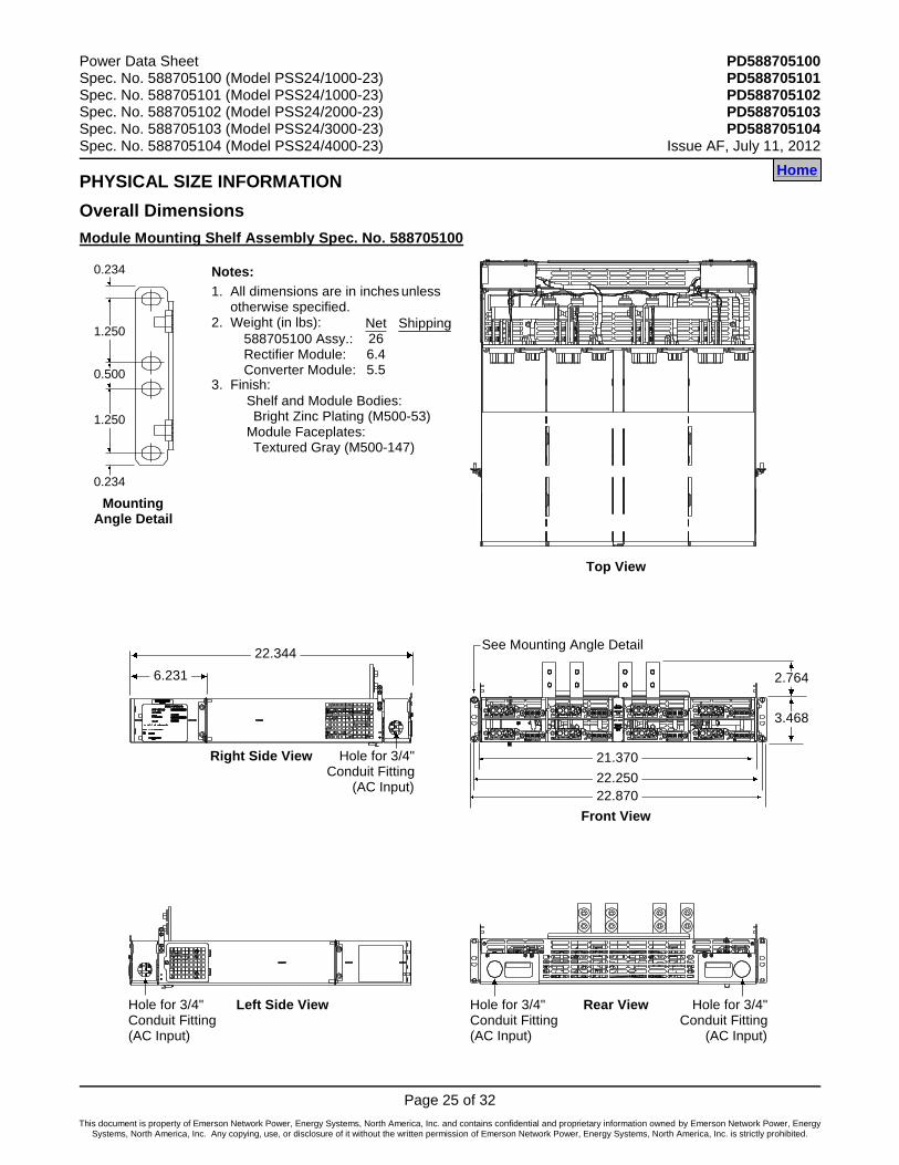
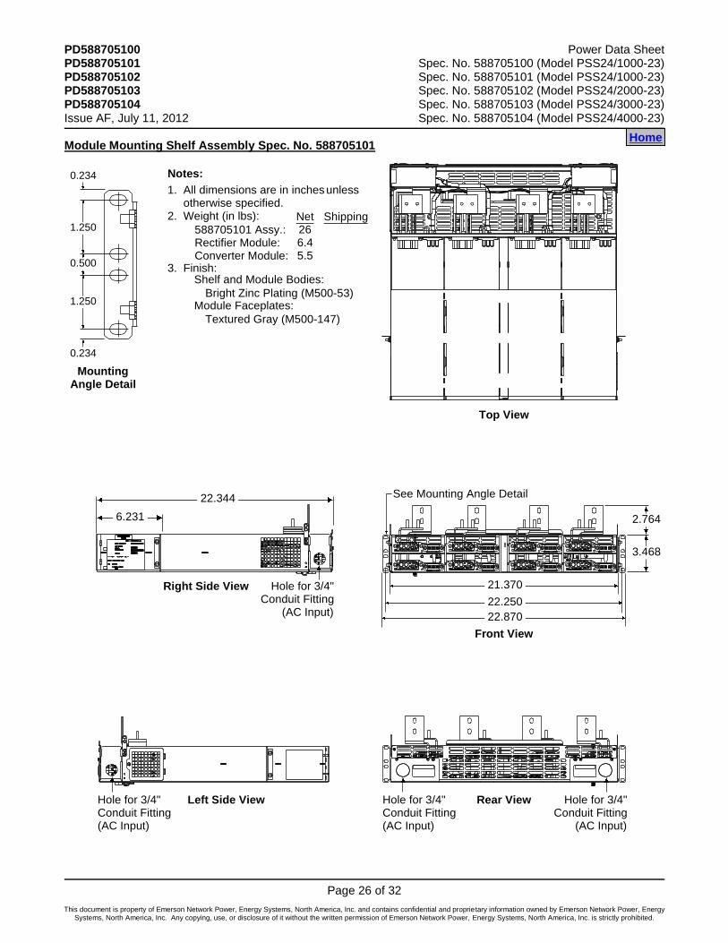
PHYSICAL SIZE INFORMATION
Overall Dimensions
Module Mounting Shelf Assembly Spec. No. 588705100
Front View
Right Side View
Left Side View
MountingAngle Detail
1.250
1.250
0.500
0.234
0.234
Rear View
All dimensions are in inches unless otherwise specified.Weight (in lbs):
Finish:
Notes:
Shelf and Module Bodies:
Module Faceplates:Bright Zinc Plating (M500-53)
Textured Gray (M500-147)
1.
2.
3.
See Mounting Angle Detail
22.870
21.370
22.250
3.468
2.764
588705100 Assy.:Rectifier Module:Converter Module:
Net266.45.5
Shipping
22.344
6.231
Hole for 3/4"Conduit Fitting
(AC Input)
Hole for 3/4"Conduit Fitting(AC Input)
Hole for 3/4"Conduit Fitting
(AC Input)
Hole for 3/4"Conduit Fitting(AC Input)
Top View
Home
PD588705100 Power Data Sheet PD588705101 Spec. No. 588705100 (Model PSS24/1000-23) PD588705102 Spec. No. 588705101 (Model PSS24/1000-23) PD588705103 Spec. No. 588705102 (Model PSS24/2000-23) PD588705104 Spec. No. 588705103 (Model PSS24/3000-23) Issue AF, July 11, 2012 Spec. No. 588705104 (Model PSS24/4000-23)
Page 26 of 32
This document is property of Emerson Network Power, Energy Systems, North America, Inc. and contains confidential and proprietary information owned by Emerson Network Power, Energy Systems, North America, Inc. Any copying, use, or disclosure of it without the written permission of Emerson Network Power, Energy Systems, North America, Inc. is strictly prohibited.
Module Mounting Shelf Assembly Spec. No. 588705101
Front View
Right Side View
Left Side View
MountingAngle Detail
1.250
1.250
0.500
0.234
0.234
Rear View
All dimensions are in inches unless otherwise specified.Weight (in lbs):
Finish:
Notes:
Shelf and Module Bodies:
Module Faceplates:Bright Zinc Plating (M500-53)
Textured Gray (M500-147)
1.
2.
3.
See Mounting Angle Detail
22.870
21.370
22.250
3.468
2.764
588705101 Assy.:Rectifier Module:Converter Module:
Net266.45.5
Shipping
Top View
22.344
6.231
Hole for 3/4"Conduit Fitting
(AC Input)
Hole for 3/4"Conduit Fitting(AC Input)
Hole for 3/4"Conduit Fitting
(AC Input)
Hole for 3/4"Conduit Fitting(AC Input)
Home
Power Data Sheet PD588705100 Spec. No. 588705100 (Model PSS24/1000-23) PD588705101 Spec. No. 588705101 (Model PSS24/1000-23) PD588705102 Spec. No. 588705102 (Model PSS24/2000-23) PD588705103 Spec. No. 588705103 (Model PSS24/3000-23) PD588705104 Spec. No. 588705104 (Model PSS24/4000-23) Issue AF, July 11, 2012
Page 27 of 32
This document is property of Emerson Network Power, Energy Systems, North America, Inc. and contains confidential and proprietary information owned by Emerson Network Power, Energy Systems, North America, Inc. Any copying, use, or disclosure of it without the written permission of Emerson Network Power, Energy Systems, North America, Inc. is strictly prohibited.
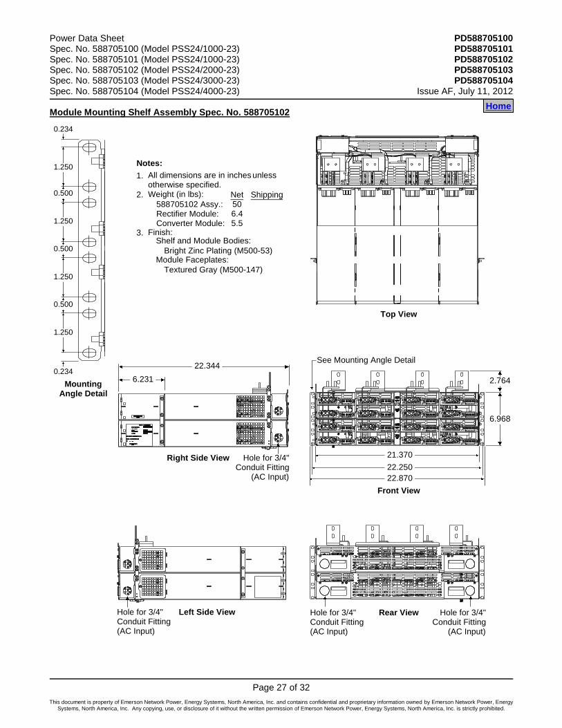
Module Mounting Shelf Assembly Spec. No. 588705102
Front View
Right Side View
Left Side View
MountingAngle Detail
Rear View
All dimensions are in inches unless otherwise specified.Weight (in lbs):
Finish:
Notes:
Shelf and Module Bodies:
Module Faceplates:Bright Zinc Plating (M500-53)
Textured Gray (M500-147)
1.
2.
3.
See Mounting Angle Detail
22.870
21.370
22.250
6.968
2.764
588705102 Assy.:Rectifier Module:Converter Module:
Net506.45.5
Shipping
Top View
22.344
6.231
Hole for 3/4"Conduit Fitting
(AC Input)
Hole for 3/4"Conduit Fitting(AC Input)
Hole for 3/4"Conduit Fitting
(AC Input)
Hole for 3/4"Conduit Fitting(AC Input)
1.250
1.250
0.500
0.234
0.234
1.250
0.500
1.250
0.500
Home
PD588705100 Power Data Sheet PD588705101 Spec. No. 588705100 (Model PSS24/1000-23) PD588705102 Spec. No. 588705101 (Model PSS24/1000-23) PD588705103 Spec. No. 588705102 (Model PSS24/2000-23) PD588705104 Spec. No. 588705103 (Model PSS24/3000-23) Issue AF, July 11, 2012 Spec. No. 588705104 (Model PSS24/4000-23)
Page 28 of 32
This document is property of Emerson Network Power, Energy Systems, North America, Inc. and contains confidential and proprietary information owned by Emerson Network Power, Energy Systems, North America, Inc. Any copying, use, or disclosure of it without the written permission of Emerson Network Power, Energy Systems, North America, Inc. is strictly prohibited.
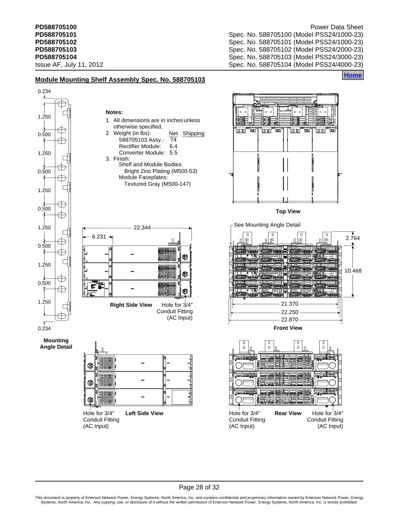
Module Mounting Shelf Assembly Spec. No. 588705103
Front View
Right Side View
Left Side View
MountingAngle Detail
Rear View
All dimensions are in inches unless otherwise specified.Weight (in lbs):
Finish:
Notes:
Shelf and Module Bodies:
Module Faceplates:Bright Zinc Plating (M500-53)
Textured Gray (M500-147)
1.
2.
3.
See Mounting Angle Detail
22.870
21.370
22.250
10.468
2.764
588705103 Assy.:Rectifier Module:Converter Module:
Net746.45.5
Shipping
Top View
22.344
6.231
Hole for 3/4"Conduit Fitting
(AC Input)
Hole for 3/4"Conduit Fitting(AC Input)
Hole for 3/4"Conduit Fitting
(AC Input)
Hole for 3/4"Conduit Fitting(AC Input)
1.250
1.250
0.500
0.234
0.234
1.250
0.500
1.250
0.500
1.250
0.500
1.250
0.500
Home

Power Data Sheet PD588705100 Spec. No. 588705100 (Model PSS24/1000-23) PD588705101 Spec. No. 588705101 (Model PSS24/1000-23) PD588705102 Spec. No. 588705102 (Model PSS24/2000-23) PD588705103 Spec. No. 588705103 (Model PSS24/3000-23) PD588705104 Spec. No. 588705104 (Model PSS24/4000-23) Issue AF, July 11, 2012
Page 29 of 32
This document is property of Emerson Network Power, Energy Systems, North America, Inc. and contains confidential and proprietary information owned by Emerson Network Power, Energy Systems, North America, Inc. Any copying, use, or disclosure of it without the written permission of Emerson Network Power, Energy Systems, North America, Inc. is strictly prohibited.
Module Mounting Shelf Assembly Spec. No. 588705104
Front View
Right Side View
Left Side View
MountingAngle Detail
Rear View
All dimensions are in inches unless otherwise specified.Weight (in lbs):
Finish:
Notes:
Shelf and Module Bodies:
Module Faceplates:Bright Zinc Plating (M500-53)
Textured Gray (M500-147)
1.
2.
3.
See Mounting Angle Detail
22.870
21.370
22.250
13.968
2.764
588705104 Assy.:Rectifier Module:Converter Module:
Net986.45.5
Shipping
Top View
22.344
6.231
Hole for 3/4"Conduit Fitting
(AC Input)
Hole for 3/4"Conduit Fitting(AC Input)
Hole for 3/4"Conduit Fitting
(AC Input)
Hole for 3/4"Conduit Fitting(AC Input)
1.250
1.250
0.500
0.234
0.234
1.250
0.500
1.250
0.500
1.250
0.500
1.250
0.500
1.250
0.500
1.250
0.500
Home
PD588705100 Power Data Sheet PD588705101 Spec. No. 588705100 (Model PSS24/1000-23) PD588705102 Spec. No. 588705101 (Model PSS24/1000-23) PD588705103 Spec. No. 588705102 (Model PSS24/2000-23) PD588705104 Spec. No. 588705103 (Model PSS24/3000-23) Issue AF, July 11, 2012 Spec. No. 588705104 (Model PSS24/4000-23)
Page 30 of 32
This document is property of Emerson Network Power, Energy Systems, North America, Inc. and contains confidential and proprietary information owned by Emerson Network Power, Energy Systems, North America, Inc. Any copying, use, or disclosure of it without the written permission of Emerson Network Power, Energy Systems, North America, Inc. is strictly prohibited.
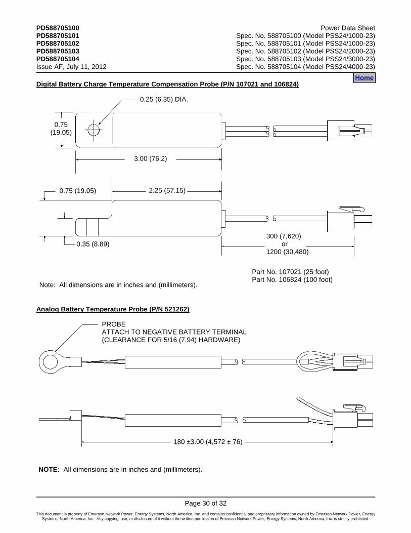
Digital Battery Charge Temperature Compensation Probe (P/N 107021 and 106824)
2.25 (57.15)0.75 (19.05)
0.35 (8.89)300 (7,620) or1200 (30,480)
0.75(19.05)
3.00 (76.2)
0.25 (6.35) DIA.
Note: All dimensions are in inches and (millimeters).
Part No. 107021 (25 foot)Part No. 106824 (100 foot)
Analog Battery Temperature Probe (P/N 521262)
NOTE: All dimensions are in inches and (millimeters).
180 ±3.00 (4,572 ± 76)
PROBEATTACH TO NEGATIVE BATTERY TERMINAL (CLEARANCE FOR 5/16 (7.94) HARDWARE)
Home Home

Power Data Sheet PD588705100 Spec. No. 588705100 (Model PSS24/1000-23) PD588705101 Spec. No. 588705101 (Model PSS24/1000-23) PD588705102 Spec. No. 588705102 (Model PSS24/2000-23) PD588705103 Spec. No. 588705103 (Model PSS24/3000-23) PD588705104 Spec. No. 588705104 (Model PSS24/4000-23) Issue AF, July 11, 2012
Page 31 of 32
This document is property of Emerson Network Power, Energy Systems, North America, Inc. and contains confidential and proprietary information owned by Emerson Network Power, Energy Systems, North America, Inc. Any copying, use, or disclosure of it without the written permission of Emerson Network Power, Energy Systems, North America, Inc. is strictly prohibited.
RELATED DOCUMENTATION
Spec. Nos. 588705100, 588705101, 588705102, 588705103, and 588705104 Module Mounting Shelf Assemblies
Schematic Diagram: SD588705100/SD588705101/SD588705102/SD588705103/SD588705104
Wiring Diagram: T588705100/T588705101/T588705102/T588705103/T588705104
Rectifiers (1R242500 and 1R243000)
Rectifier Instructions: UM1R243000
Converter (1C24481500)
Converter Instructions: UM1C24481500
Spec. No. 581126000 NetSure Power System
System Application Guide: SAG581126000
System Installation Instructions: Section 6012
System User Instructions: Section 6013
Color MCA Menu Tree: Section 6022
Home

PD588705100 Power Data Sheet PD588705101 Spec. No. 588705100 (Model PSS24/1000-23) PD588705102 Spec. No. 588705101 (Model PSS24/1000-23) PD588705103 Spec. No. 588705102 (Model PSS24/2000-23) PD588705104 Spec. No. 588705103 (Model PSS24/3000-23) Issue AF, July 11, 2012 Spec. No. 588705104 (Model PSS24/4000-23)
Page 32 of 32
This document is property of Emerson Network Power, Energy Systems, North America, Inc. and contains confidential and proprietary information owned by Emerson Network Power, Energy Systems, North America, Inc. Any copying, use, or disclosure of it without the written permission of Emerson Network Power, Energy Systems, North America, Inc. is strictly prohibited.
REVISION RECORD
Issue Change Number (ECO)
Description of Change Date Approved
AA LLP211093 New 06/30/08 John Jasko
AB LLP212232 Updated heat dissipation values in Paragraph 2.2.5.
04/22/09 John Jasko
AC LLP212882 Fan Failure statement added for NEBS. 09/28/09 John Jasko
AD LLP214892 Added 1R243000 rectifier to the existing power system of 581126000. Added and updated charts for rectifier specifications.
12/09/10 Khristebelle Ilagan
AE LLP215944
Adding compatibility information for 1R483500e rectifiers in systems with older software. Removing rectifier/converter module specs. from this document and referencing the separate rectifier/converter document.
08/11/11 John Jasko
AF LLP217111 DC-DC Converter Option Kit P/N 540806 is included with 588705100 List 1. Description revised.
07/11/12 John Jasko
Home
Emerson Network Power, Energy Systems, North America, Inc. 4350 Weaver Parkway, Warrenville, IL 60555 Toll Free: 800-800-1280 (USA and Canada) Telephone: 440-246-6999 Fax: 440-246-4876 Web: EmersonNetworkPower.com/EnergySystems
EnergyNet: Secure.EmersonNetworkPower.com
John JaskoJul 12, 2012Ray MannJul 12, 2012