homelite weed eater
DESCRIPTION
homelite weed eater user manualTRANSCRIPT

SAVE THIS MANUAL FOR FUTURE REFERENCE
Your new trimmer has been engineered and manufactured to Homelite’s high standard for dependability, ease of operation, andoperator safety. Properly cared for, it will give you years of rugged, trouble-free performance.
Thank you for buying a Homelite trimmer.
WARNING: To reduce the risk of injury, the user must read and understand the operator’s manual.
STOPOP
12
3
STSTOP
12
3
STSTOPOP
12
3
Easy Reach model UT20778
Trim ‘n Edge model UT20779
Trimlite model UT20763
OPERATOR'S MANUAL25cc String Trimmers

Page 2
■■■■■ Introduction ................................................................................................................................................................. 2
■■■■■ Important Safety Instructions ................................................................................................................................. 2 - 3
■■■■■ Symbols ...................................................................................................................................................................... 4
■■■■■ Specifications .............................................................................................................................................................. 5
■■■■■ Unpacking ................................................................................................................................................................... 5
■■■■■ Features ................................................................................................................................................................. 5 - 6
■■■■■ Assembly ............................................................................................................................................................... 7 - 8
■■■■■ Operation .............................................................................................................................................................. 9 - 12
■■■■■ Maintenance ....................................................................................................................................................... 13 - 15
■■■■■ Troubleshooting ................................................................................................................................................... 16 - 17
■■■■■ Warranty ............................................................................................................................................................. 18 - 20
■■■■■ Service Parts ............................................................................................................................................................. 21
■■■■■ Parts Ordering / Service ............................................................................................................................................ 22
WARNINGDo not attempt to operate this trimmer until you have read thoroughly and understand completely all instructions,safety rules, etc. contained in this manual. Failure to comply can result in accidents involving fire, electric shock,or serious personal injury. Save operator's manual and review frequently for continuing safe operation, andinstructing others who may use this tool.
Trimming weeds and grass is an easy task using this Homelite string trimmer. Safety, performance, and dependability havebeen given top priority in the design of this string trimmer making it easy to maintain and operate.
IMPORTANT SAFETY INSTRUCTIONS
INTRODUCTION
TABLE OF CONTENTS
READ ALL INSTRUCTIONSGENERAL SAFETY RULES■ For safe operation, read and understand all instructions
before using the trimmer. Follow all safety instructions.Failure to follow all safety instructions listed below, canresult in serious personal injury.
■ Do not allow children or untrained individuals to use thisunit.
■■■■■ Never start or run the engine in a closed or poorlyventilated area; breathing exhaust fumes can kill.
■■■■■ Clear the work area before each use. Remove all objectssuch as rocks, broken glass, nails, wire, or string whichcan be thrown or become entangled in the string head orblade.
■■■■■ Wear eye and hearing protection while operating thisunit.
■■■■■ Wear heavy long pants, boots, and gloves. Do not wearloose fitting clothing, short pants, jewelry of any kind, orgo barefoot.

Page 3
■■■■■ Product users on United States Forest Service land, andin some states, must comply with fire prevention regula-tions. This product is equipped with a spark arrestor;however, other user requirements may apply. Check withyour federal, state, or local authorities.
■■■■■ Wear eye protection which is marked to comply withANSI Z87.1 as well as hearing protection when operatingthis equipment.
■■■■■ Wear heavy long pants, shoes, and gloves.
■■■■■ Keep all bystanders, children, and pets at least 50 feet(15 m) away.
■■■■■ Do not wear loose clothing, or jewelry.
■■■■■ Secure long hair so it is above shoulder level to prevententanglement in any moving parts.
■■■■■ Do not operate this trimmer when you are tired, ill, orunder the influence of alcohol, drugs, or medication.
■■■■■ Do not operate in poor lighting.
■■■■■ Keep firm footing and balance. Do not overreach.Overreaching can result in loss of balance or exposureto hot surfaces.
■■■■■ Keep all parts of your body away from any moving part.
■■■■■ Do not touch area around the muffler or cylinder of thetrimmer, these parts get hot from operation.
■■■■■ Always stop the engine and remove the spark plug wirebefore making any adjustments or repairs except forcarburetor adjustments.
■■■■■ It has been reported that vibrations from hand-held toolsmay contribute to a condition called Raynaud’s Syn-drome in certain individuals. Symptoms may includetingling, numbness and blanching of the fingers, usuallyapparent upon exposure to cold. Hereditary factors,exposure to cold and dampness, diet, smoking and workpractices are all thought to contribute to the developmentof these symptoms. It is presently unknown what, if any,vibrations or extent of exposure may contribute to thecondition. There are measures that can be taken by theoperator to possibly reduce the effects of vibration:
a) Keep your body warm in cold weather. When operat-ing the unit wear gloves to keep the hands and wristswarm. It is reported that cold weather is a majorfactor contributing to Raynaud’s Syndrome.
IMPORTANT SAFETY INSTRUCTIONS
b) After each period of operation, exercise to increaseblood circulation.
c) Take frequent work breaks. Limit the amount ofexposure per day.
d) Keep the tool well maintained, fasteners tightenedand worn parts replaced.
If you experience any of the symptoms of this condition,immediately discontinue use and see your physicianabout these symptoms.
■■■■■ Mix and store fuel in a container approved for gasoline.
■■■■■ Mix fuel outdoors where there are no sparks or flames.Wipe up any fuel spillage. Move 30 ft. (9 m) away fromrefueling site before starting engine.
■■■■■ Stop the engine and allow to cool before refueling orstoring the unit.
■■■■■ Allow the engine to cool; empty the fuel tank and securethe unit from moving before transporting in a vehicle.
SPECIFIC SAFETY RULES FOR TRIMMER USE■■■■■ Replace string head if cracked, chipped, or damaged in
any way. Be sure the string head is properly installedand securely fastened. Failure to do so can causeserious injury.
■■■■■ Make sure all guards, straps, deflectors and handles areproperly and securely attached.
■■■■■ Use only the manufacturer's replacement string in thecutting head. Do not use any other cutting attachment.
■■■■■ Never operate unit without the grass deflector in placeand in good condition.
■■■■■ Maintain a firm grip on both handles while trimming. Keepstring head below waist level. Never cut with the stringhead located over 30 in. (76 cm) or more above theground.

Page 4
Important: Some of the following symbols may be used on your tool. Please study them and learn their meaning.Proper interpretation of these symbols will allow you to operate the tool better and safer.
SYMBOL NAME EXPLANATION
Safety Alert Symbol Indicates danger, warning or caution. It meansattention!!! Your safety is involved.
Read Your Operator’s Manual Your manual contains special messages tobring attention to potential safety concerns,machine damage as well as helpful operating andservicing information. Please read all theinformation carefully to avoid injury and machinedamage.
Wear eye and hearing protection. Wear eye protection which is marked to complywith ANSI Z87.1 as well as hearing protectionwhen operating this equipment.
Keep bystanders away. Keep all bystanders at least 50 ft. (15 m)away.
Ricochet. Danger of Ricochet.
No blade. Do not install any type of blade on this unit.
SYMBOLS
The purpose of safety symbols is to attract your attention to possible dangers. The safety symbols, and the explanationswith them, deserve your careful attention and understanding. The safety warnings do not by themselves eliminate anydanger. The instructions or warnings they give are not substitutes for proper accident prevention measures.
SYMBOL MEANING
DANGER: Indicates an imminently hazardous situation which, if not avoided, will result in death or
serious injury.
WARNING: Indicates a potentially hazardous situation which, if not avoided, could result in serious
injury.
CAUTION: Indicates a potentially hazardous situation which, if not avoided, may result in minor or
moderate injury. It may also be used to alert against unsafe practices that may cause property damage.
NOTE: Advises you of information or instructions vital to the operation or maintenance of the equipment.
SAVE THESE INSTRUCTIONS

Page 5
STSTOP
12
3
Weight - (without fuel) ............................................................................................................................ 9.1 lbs. (4.13 kg.)
Cutting swath ............................................................................................................................................ 17 in. (432 mm)
Engine displacement ................................................................................................................................................. 25cc
String diameter ....................................................................................................................................... .080 in. (2.0 mm)
FEATURES
SPECIFICATIONS
FEATURES
Fig. 1a
THROTTLE TRIGGER
STARTER GRIPCHOKE LEVER
REAR HANDLEFRONT HANDLE
DRIVE SHAFTHOUSING
STRING HEAD
GRASS DEFLECTOR
STOP BUTTON
PRIMER BULB
Trimlite modelUT20763
FEATURESUNPACKING
INSTRUCTIONS■■■■■ Carefully remove the product from the carton.
■■■■■ Inspect the product to make sure no breakage ordamage occurred during shipping.
■■■■■ Do not discard the packing material until you haveinspected and operated the product.
■■■■■ If any parts are damaged or missing, please call1-800-chainsaw (1-800-242-4672) for assistance.
PACKING LIST■■■■■ Trimmer Assembly
■■■■■ Owner’s Kit
■■■■■ Front handle
■■■■■ Grass deflector
■■■■■ Edger Guide for Trim ‘n Edge only
■■■■■ Hardware Bags (2)
■■■■■ Bottle of 2-Cycle Oil
■■■■■ Operator's manual

Page 6
STSTOPOP
12
3
STOPOP
12
3
FEATURES
Fig. 1b
Fig. 1c
EDGER ATTACHMENT(TRIM ‘N EDGE ONLY)
THROTTLE TRIGGER
STARTER GRIPCHOKE LEVER
REAR HANDLEFRONT HANDLE
DRIVE SHAFTHOUSING
STRING HEAD
GRASS DEFLECTOR
STOP BUTTON
PRIMER BULB
THROTTLE TRIGGER
STARTER GRIPCHOKE LEVER
REAR HANDLEFRONT HANDLE
DRIVE SHAFTHOUSING
STRING HEAD
GRASS DEFLECTOR
STOP BUTTON
PRIMER BULB
Trim ‘n Edge modelUT20779
Easy Reach modelsUT20778

Page 7
If your unit has been preassembled, check each step to makesure the unit has been properly assembled.
FRONT HANDLESee Figure 2.1. Remove the front handle, bolt, and wing nut from the
Owner’s Kit.
2. Install the front handle onto the top side of the driveshaft housing and move it to a comfortable position.
3. Place the bolt through the front handle as shown, theninstall the wing nut.
4. Tighten wing nut securely.
GRASS DEFLECTOR WITHOUT EDGERGUIDE - TRIMLITE AND TRIM ‘N EDGESee Figure 3.1. Remove wing nut, flat washer, lock washer, and bolt
from the Owner’s Kit.
2. Place grass deflector over shaft and bracket.
3. Install bolt through the slots in the tabs on grass deflec-tor and bracket on shaft housing.
4. Install flat washer, lock washer and wing nut.
5. Tighten Securely.
GRASS DEFLECTOR WITH EDGER GUIDE -TRIM ‘N EDGE ONLYEDGER GUIDE ASSEMBLYSee Figure 4.1. Assemble the two plastic pieces of the edger guide
together using the short bolt, flat washer, lock washerand wing nut.
2. Slide the edger guide to adjust it to the desired trimminglength.
3. Tighten the wing nut securely.
GRASSDEFLECTOR
BRACKET
BOLT
WING NUT Fig. 3
WING NUT
FRONT HANDLE
BOLT
Fig. 2
FLATWASHER
LOCK WASHER
ASSEMBLY
EDGER GUIDEPIECES
SHORT BOLT
FLAT WASHER
LOCKWASHER
WING NUT
Fig. 4

Page 8
ASSEMBLEDEDGER GUIDE
TABS
GRASS DEFLECTOR WITH EDGER GUIDE -TRIM ‘N EDGE ONLY (Continued)See Figures 5 and 6.1. Remove the wing nut, flat washer, lock washer, and bolt
from the Owner’s Kit.
2. Place the grass deflector over the shaft and bracket.
3. Slide the assembled edger guide over the tabs on thegrass deflector and bracket.
4. Place the bolt through the slots in the tabs on the grassdeflector and trimmer.
NOTE: Ensure the slots are aligned before installing thebolt.
5. Install the flat washer, lock washer and wing nut.
6. Tighten the wing nut securely.
GRASS DEFLECTOR - EASY REACHSee Figure 7.1. Remove the wing nut from the Owner's Kit.
2. Place slot in grass deflector over the square tab of themounting bracket.
3. Rotate the deflector around the drive shaft housing theninsert the screw on the grass deflector into the screwhole in the mounting bracket. The mounting surface ofthe grass deflector should fit flush on the mountingbracket.
4. Install the wing nut and tighten securely.
FLATWASHER
LOCKWASHER
WING NUT
LONG BOLT
Fig. 6
WING NUT
GRASSDEFLECTOR
SLOT
SCREW
SQUARE TAB
Fig. 7
Fig. 5
ASSEMBLY

Page 9
���������������������������������������������FUELING AND REFUELING THE TRIMMERFUEL MIXTUREThis product is powered by a 2-cycle engine and requirespre-mixing gasoline and 2-cycle oil. Pre-mix unleadedgasoline and 2-cycle engine oil in a clean 1 gallon containerapproved for gasoline.
Recommended fuel: This engine is certified to operate onunleaded gasoline intended for automotive use.
Mix Homelite Premium Exact Mix oil with gasoline accord-ing to the instructions on the package. If Premium ExactMix oil is not available, use a high quality 2-cycle engineoil, mixed at 2.6 oz. per gallon (US).
Do not use automotive oil or 2-cycle outboard oil.
NOTE: Premium Exact Mix fuel mix will stay fresh up to 30days.DO NOT mix quantities larger than usable in a 30 day period.
FUEL MIXTURE
WARNING:Always shut off engine before fueling. Never add fuelto a machine with a running or hot engine. Move atleast 30 ft. (9 m) from refueling site before startingengine. Do not smoke!
OPERATING THE TRIMMERSee Figure 8.Hold the trimmer with the right hand on the rear handle andthe left hand on the front handle. Keep a firm grip with bothhands while in operation. Trimmer should be held at acomfortable position with the rear handle about hip height.
Always operate trimmer at full throttle. Cut tall grass fromthe top down. This will prevent grass from wrapping aroundthe shaft housing and string head which may cause dam-age from overheating. If grass becomes wrapped aroundthe string head, STOP THE ENGINE, disconnect the sparkplug wire, and remove the grass. Prolonged cutting atpartial throttle will result in oil dripping from the muffler.
FILLING TANK1. Clean surface around fuel cap to prevent contamination.
2. Loosen fuel cap slowly. Rest the cap on a clean surface.
3. Carefully pour fuel into the tank. Avoid spillage.
4. Prior to replacing the fuel cap, clean and inspect thegasket.
5. Immediately replace fuel cap and hand tighten. Wipe upany fuel spillage.
NOTE: It is normal for smoke to be emitted from a newengine after first use.
PREMIUM EXACT MIX (50:1)GASOLINE OIL1 gallon (US) 2.6 oz.
1 Liter 20 cc (20 ml)
Fig. 8
OPERATION

Page 10
ADVANCING THE STRINGADVANCING STRING USING THE EZ LINE™ TAPADVANCE SYSTEMString advance is controlled by tapping string head on grasswhile running engine at full throttle.
1. Run engine at full throttle.
2. Tap string head on ground to advance string. Stringadvances each time the head is tapped.
3. Several taps may be required until string strikes the cutoff blade.
4. Resume trimming.
NOTE: If the string is worn too short you may not be able toadvance the string by tapping it on the ground. If so, STOPTHE ENGINE, and manually advance the string.
ADVANCING THE STRING MANUALLYPush the spool retainer down while pulling on string(s) tomanually advance the string.
CUT OFF BLADEThis trimmer is equipped with a cut-off blade on the grassdeflector. For best cutting, advance string until it is trimmedto length by the cut-off blade. Advance string whenever youhear the engine running faster than normal. This will main-tain best performance and keep string long enough toadvance properly.
CUTTING TIPSSee Figure 9.■ Keep the trimmer tilted toward the area being cut; this is
the best cutting area.
■ Do not cut in dangerous cutting area.
■ Use the tip of string to do the cutting; do not force stringhead into uncut grass.
■ Wire and picket fences cause extra string wear, evenbreakage. Stone and brick walls, curbs, and wood maywear string rapidly.
■ Avoid trees and shrubs. Tree bark, wood moldings,siding, and fence posts can easily be damaged by thestring.
DANGEROUSCUTTING AREA
Fig. 9BEST CUTTING AREA
OPERATION

Page 11
EDGER GUIDE OPERATION - TRIM ‘N EDGEONLYSee Figures 10 and 11.■ Loosen the wing nut and slide the edger guide to adjust it
to the desired trimming length then retighten the wing nutsecurely. Refer to “Edger Guide Assembly” earlier in thismanual for additional information.
■ The edger guide allows the trimmer to be used as anedger for cutting along sidewalks, driveways, flowerbeds, etc. The edger guide is convenient to use andsupports the trimmer as it is being used as an edger.
■ Be extremely careful when tilting the trimmer to use asan edger. The muffler, and the exhaust from the mufflerget very hot during operation. Keep the muffler awayfrom all body parts. See Figure 11.
Fig. 11
OPERATION
Fig. 10
WING NUT
EDGER GUIDE

Page 12
STOPOP
12
3
STARTING AND STOPPINGSee Figure 12 and 13.
TO START A COLD ENGINE:1. Lay the trimmer on a flat, bare surface.
2. Push the primer bulb 8 to 10 times.
3. Set the choke lever to the choke position .
4. Squeeze the throttle trigger to the full throttle position.
5. Pull the starter until the engine tries to run. No morethan 6 pulls.
6. Set the choke lever to the half choke position .
7. Hold the trigger and the pull starter rope until the engineruns.
8. Run the engine 30 to 45 seconds at full throttle (with thetrigger depressed fully) on half choke position towarm up the engine. Move the choke lever to the runposition .
TO START A WARM ENGINE:1. Move the choke lever to the run position .
2. Hold the trigger and pull the starter rope until the engineruns.
TO STOP THE ENGINE:To stop the engine, push and hold the STOP button until theengine stops.
HALFCHOKE
POSITION
PRIMER BULB
CHOKE LEVER
STOP BUTTON
CHOKEPOSITION
RUN POSITION
Fig. 13
Fig. 12
THROTTLETRIGGER
PRIMER BULB
OPERATION
Page 13
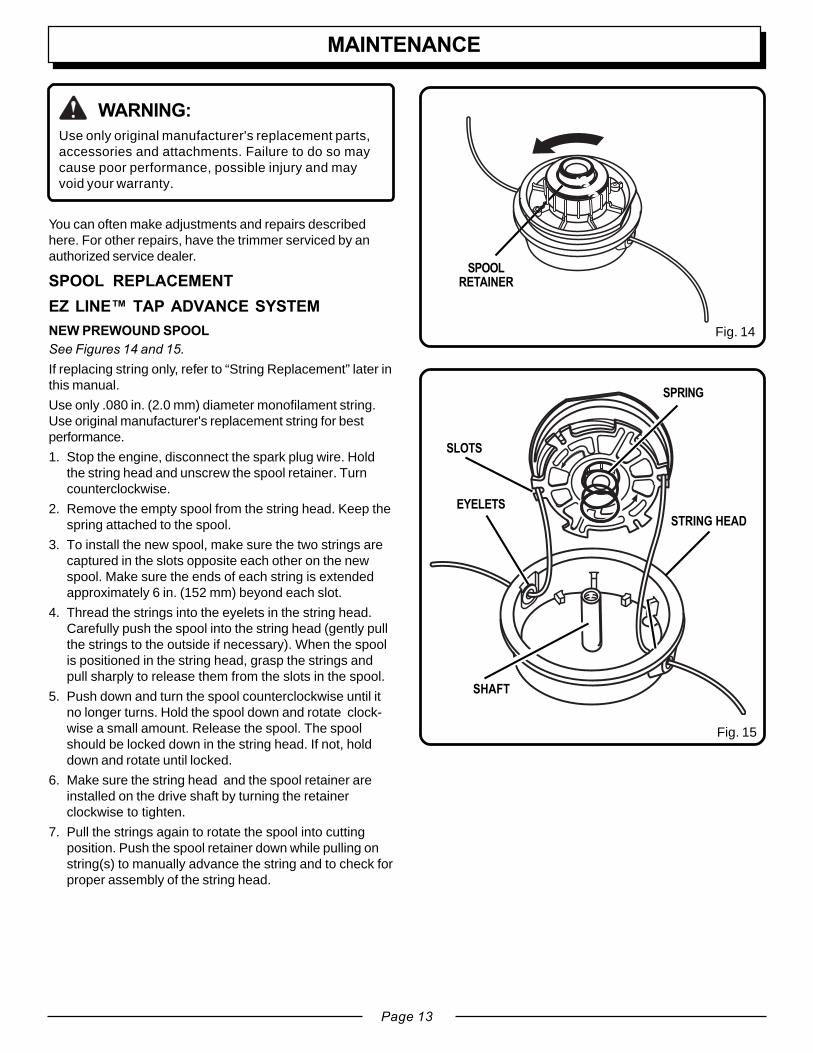
You can often make adjustments and repairs describedhere. For other repairs, have the trimmer serviced by anauthorized service dealer.
SPOOL REPLACEMENTEZ LINE™ TAP ADVANCE SYSTEMNEW PREWOUND SPOOLSee Figures 14 and 15.If replacing string only, refer to “String Replacement” later inthis manual.
Use only .080 in. (2.0 mm) diameter monofilament string.Use original manufacturer's replacement string for bestperformance.
1. Stop the engine, disconnect the spark plug wire. Holdthe string head and unscrew the spool retainer. Turncounterclockwise.
2. Remove the empty spool from the string head. Keep thespring attached to the spool.
3. To install the new spool, make sure the two strings arecaptured in the slots opposite each other on the newspool. Make sure the ends of each string is extendedapproximately 6 in. (152 mm) beyond each slot.
4. Thread the strings into the eyelets in the string head.Carefully push the spool into the string head (gently pullthe strings to the outside if necessary). When the spoolis positioned in the string head, grasp the strings andpull sharply to release them from the slots in the spool.
5. Push down and turn the spool counterclockwise until itno longer turns. Hold the spool down and rotate clock-wise a small amount. Release the spool. The spoolshould be locked down in the string head. If not, holddown and rotate until locked.
6. Make sure the string head and the spool retainer areinstalled on the drive shaft by turning the retainerclockwise to tighten.
7. Pull the strings again to rotate the spool into cuttingposition. Push the spool retainer down while pulling onstring(s) to manually advance the string and to check forproper assembly of the string head.
WARNING:Use only original manufacturer's replacement parts,accessories and attachments. Failure to do so maycause poor performance, possible injury and mayvoid your warranty.
Fig. 14
Fig. 15
SPOOLRETAINER
SPRING
SLOTS
STRING HEAD
EYELETS
SHAFT
MAINTENANCE

Page 14
MAINTENANCE
STRING REPLACEMENTSee Figures 16, 17, 18 and 19.1. Stop the engine, disconnect the spark plug wire. Hold
the string head and unscrew the spool retainer. Turncounterclockwise.
2. Remove the spool from the string head. NOTE: Keepthe spring attached to the spool. Remove any old stringremaining on the spool.
3. Cut two pieces of string, each being approximately 9 ft.(2.7 m) long. Use only .080 in. (2.0 mm) diametermonofilament string.
4. Insert the first string into the anchor hole in the upperpart of the spool. Wind the first string around the upperpart of the spool counterclockwise, as shown by thearrows on the spool. Place string in the slot on upperspool flange, leaving about 6 in. (152 mm) extendedbeyond the slot. Do not overfill. After winding the string,there should be at least 1/4 in. (6 mm) between thewound string and the outside edge of the spool.
5. Repeat above step with second string, using the bottompart of spool. Do not overfill.
6. Replace the spool and the spool retainer. Refer to "SpoolReplacement " earlier in this manual.
CLEANING THE EXHAUST PORT ANDMUFFLERNOTE: Depending on the type of fuel used, the type andamount of oil used, and/or your operating conditions, theexhaust port and muffler may become blocked with carbondeposits. If you notice a power loss with your gas poweredtool, you may need to remove these deposits to restoreperformance. We highly recommended that only qualifiedservice technicians perform this service.
SPARK ARRESTORThe spark arrestor must be cleaned or replaced every 25hours or yearly to ensure proper performance of yourproduct. Spark arrestors may be in different locationsdepending on the model purchased. Please contact yournearest service dealer for the location of the spark arrestorfor your model.
Cleaning Instructions:■■■■■ Remove the spark arrestor from the muffler.
■■■■■ If your spark arrestor is made of a fiberglass material,discard and replace.
■■■■■ If your spark arrestor is made of a metal material followthese cleaning instructions:
1. Spray the spark arrestor with a quality carboncleaner.
2. Gently clean using a wire brush.
3. Install the new or cleaned spark arrestor and reas-semble completely before use.
Fig. 18
Fig. 19
SPRING
Fig. 17
SLOT ARROWS ONSPOOL
SECONDSTRING
FIRST STRING Fig. 16
SPOOL
ANCHORHOLE
ARROWS ONSPOOL
FIRST STRING
SLOT

Page 15
STSTOPOP
12
3
21
3
STOP
The fuel cap contains a non-serviceable filter and a checkvalve. A clogged fuel filter will cause poor engine perfor-mance. If performance improves when the fuel cap isloosened, check valve may be faulty or filter clogged.Replace fuel cap if required.
SPARK PLUGThis engine uses a NSK # BPMR7A spark plug with.025 in. (0.63 mm) electrode gap. Use an exact replace-ment and replace annually, or more frequently if necessary.
STORING THE TRIMMER (1 MONTH ORLONGER)1. Drain all fuel from tank into a container approved for
gasoline. Run engine until it stops.
2. Clean all foreign material from the trimmer. Store it in awell-ventilated place that is inaccessible to children.Keep away from corrosive agents such as gardenchemicals and de-icing salts.
3. Abide by all Federal and local regulations for the safestorage and handling of gasoline. Excess fuel should beused up in other 2-cycle engine powered equipment.
REPLACING AND CLEANING AIR FILTERSee Figures 20 and 21.For proper performance and long life, keep air filter clean.
1. Remove the air filter cover by pushing down on the latchwith your thumb while gently pulling on the cover.
2. Remove the filter, clean it in warm soapy water. Rinseand let dry completely. For best performance, replaceannually.
3. Install the filter, align tabs, push in, and make sure thelatch snaps and latches into place.
FUEL CAP
WARNING:A leaking fuel cap is a fire hazard and must bereplaced immediately.
AIR FILTERCOVER
FILTER
Fig. 20
Fig. 21
MAINTENANCE
STSTOPOP
12
3
LATCH
PULL COVERTO OPEN

Page 16
PROBLEMPROBLEMPROBLEMPROBLEMPROBLEM POSPOSPOSPOSPOSSIBLE CASIBLE CASIBLE CASIBLE CASIBLE CAUSEUSEUSEUSEUSE SOLUTIONSOLUTIONSOLUTIONSOLUTIONSOLUTION
1. To check for spark: Disconnect the spark plugwire. Reattach the spark plug wire and lay sparkplug on metal cylinder. Pull the starter rope andwatch for spark at spark plug tip. If there is nospark, repeat test with a new spark plug.
2. Push primer bulb until bulb is full of fuel. Ifbulb does not fill, primary fuel delivery systemis blocked. Contact a service dealer. If primerbulb fills, engine may be flooded (see nextitem).
3. Remove spark plug, turn trimmer so spark plughole is aimed at the ground. Move choke leverto “RUN” and pull starter cord 10 to 15 times.This will clear excess fuel from engine. Cleanand reinstall spark plug. Pull starter threetimes with choke lever at “RUN”. If enginedoes not start, move choke lever to “CHOKE”and repeat normal starting procedure. If enginestill fails to start, repeat procedure with a newspark plug.
4. Contact a service dealer.
Contact a service dealer.
Turn mixture needle counterclockwise 1/16 turn.See Figure 22.
1. Use fresh fuel and the correct 2-cycle oil mix.2. Clean air filter. Refer to “Replacing and
Cleaning Air Filter” earlier in this manual.3. Turn mixture needle clockwise 1/16 turn. See
Figure 22.
Turn idle speed screw clockwise to increase idlespeed. See Figure 22.
1. Lubricate with silicone spray.2. Install more string. Refer to “String Replace-
ment” earlier in this manual.3. Pull strings while alternately pressing down on
and releasing spool retainer.4. Remove string from spool and rewind. Refer to
“String Replacement” earlier in this manual.5. Advance string at full throttle.
Engine will not start:
Engine starts but will notaccelerate:
Engine starts but will onlyrun at high speed at halfchoke:
Engine does not reach fullspeed and emits excessivesmoke:
Engine starts, runs, andaccelerates but will notidle:
String will not advance:
1. No spark.
2. No fuel.
3. Flooded engine.
4. Starter rope pulls harder now thanwhen new.
Carburetor requires adjustment.
Carburetor requires adjustment.
1. Check oil fuel mixture.2. Air filter dirty.
3. Carburetor requires adjustment.
Carburetor requires adjustment.
1. String welded to itself.2. Not enough string on spool.
3. String worn too short.
4. String tangled on spool.
5. Engine speed too slow.
TROUBLESHOOTING
Page 17
STOPOP
12
3
PROBLEMPROBLEMPROBLEMPROBLEMPROBLEM POSPOSPOSPOSPOSSIBLE CASIBLE CASIBLE CASIBLE CASIBLE CAUSEUSEUSEUSEUSE SOLUTIONSOLUTIONSOLUTIONSOLUTIONSOLUTION
Fig. 22
1. Cut tall grass from the top down.
2. Operate trimmer at full throttle.
Clean threads and lubricate with grease - if no improve-ment, replace spool retainer.
1. Operate trimmer at full throttle.
2. Use fresh fuel and the correct 2-cycle oil mix.3. Clean air filter. Refer to “Replacing and Cleaning Air
Filter” earlier in this manual.4. Turn mixture needle clockwise 1/16 turn. See Figure
22.
1. Cutting tall grass at groundlevel.
2. Operating trimmer at partthrottle.
Screw threads dirty or damaged.
1. Operating trimmer at partthrottle
2. Check oil/fuel mixture.3. Air filter dirty.
4. Carburetor requires adjust-ment.
Grass wraps aroundshaft housing andstringhead:
Spool retainer hard toturn:
Oil drips from muffler:
TROUBLESHOOTING
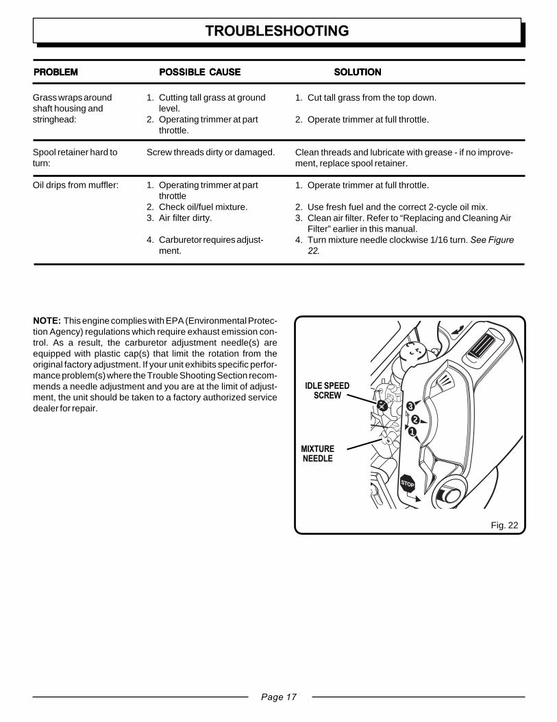
MIXTURENEEDLE
IDLE SPEEDSCREW
NOTE: This engine complies with EPA (Environmental Protec-tion Agency) regulations which require exhaust emission con-trol. As a result, the carburetor adjustment needle(s) areequipped with plastic cap(s) that limit the rotation from theoriginal factory adjustment. If your unit exhibits specific perfor-mance problem(s) where the Trouble Shooting Section recom-mends a needle adjustment and you are at the limit of adjust-ment, the unit should be taken to a factory authorized servicedealer for repair.

Page 18
WARRANTY
LIMITED WARRANTY STATEMENTHomelite Consumer Product, Inc. warrants to the original retailpurchaser that this HOMELITE product is free from defect inmaterial and workmanship and agrees to repair or replace, atHomelite Consumer Products, Inc.’s discretion, any defectiveproduct free of charge within these time periods from the date ofpurchase.■■■■■ One year for the following units: UT08110, UT20760, UT10901;■■■■■ Two years for all other Homelite products, if the product is used
for personal, family or household use;■■■■■ 90 days, if any of the above products are used for product used
for any other purpose, such as commercial or rental.This warranty extends to the original retail purchaser only andcommences on the date of the original retail purchase.Any part of the HOMELITE product manufactured or supplied byHOMELITE and found in the reasonable judgment of HOMELITE tobe defective in material or workmanship will be repaired or replacedby an authorized HOMELITE service dealer without charge forparts and labor.The HOMELITE product including any defective part must bereturned to an authorized service dealer within the warranty period.The expense of delivering the HOMELITE product to the dealer forwarranty work and the expense of returning it back to the ownerafter repair or replacement will be paid by the owner. HOMELITE’Sresponsibility in respect to claims is limited to making the requiredrepairs or replacements and no claim of breach of warranty shall because for cancellation or rescission of the contract of sale of anyHOMELITE product. Proof of purchase will be required by thedealer to substantiate any warranty claim. All warranty work mustbe performed by an authorized HOMELITE service dealer.This warranty is limited to ninety (90) days from the date of originalretail purchase for any HOMELITE product that is used for rental orcommercial purposes, or any other income-producing purpose.This warranty does not cover any HOMELITE product that hasbeen subject to misuse, neglect, negligence, or accident, or thathas been operated in any way contrary to the operating instructionsas specified in the HOMELITE operator’s manual. This warrantydoes not apply to any damage to the HOMELITE product that is theresult of improper maintenance or to any HOMELITE product thathas been altered or modified. The warranty does not extend torepairs made necessary by normal wear or by the use of parts oraccessories which are either INCOMPATIBLE WITH THEHOMELITE product or adversely affect its operation, performanceor durability.
In addition, this warranty does not cover:A. Tune-ups – Spark Plugs, Carburetor, Carburetor Adjustments,
Ignition, FiltersB. Wear items – Bump Knobs/Spool Retainers, Outer Spools, Cutting
Lines, Inner Reels, Starter Pulley, Starter Ropes, Drive BeltsHOMELITE reserves the right to change or improve the design ofany HOMELITE product without assuming any obligation to modifyany product previously manufactured.ALL IMPLIED WARRANTIES ARE LIMITED IN DURATION TOTHE STATED WARRANTY PERIOD. ACCORDINGLY, ANY SUCHIMPLIED WARRANTIES INCLUDING MERCHANTABILITY,FITNESS FOR A PARTICULAR PURPOSE, OR OTHERWISE,ARE DISCLAIMED IN THEIR ENTIRETY AFTER THEEXPIRATION OF THE APPROPRIATE TWO-YEAR, ONE-YEAR,OR NINETY DAY WARRANTY PERIOD. HOMELITE’SOBLIGATION UNDER THIS WARRANTY IS STRICTLY ANDEXCLUSIVELY LIMITED TO THE REPAIR OR REPLACEMENTOF DEFECTIVE PARTS AND HOMELITE DOES NOT ASSUMEOR AUTHORIZE ANYONE TO ASSUME FOR THEM ANY OTHEROBLIGATION. SOME STATES DO NOT ALLOW LIMITATIONSON HOW LONG AN IMPLIED WARRANTY LASTS, SO THEABOVE LIMITATION MAY NOT APPLY TO YOU. HOMELITEASSUMES NO RESPONSIBILITY FOR INCIDENTAL,CONSEQUENTIAL OR OTHER DAMAGES INCLUDING, BUT NOLIMITED TO EXPENSE OF RETURNING THE HOMELITEPRODUCT TO AN AUTHORIZED SERVICE DEALER ANDEXPENSE OF DELIVERING IT BACK TO THE OWNER,MECHANIC’S TRAVEL TIME, TELEPHONE OR TELEGRAMCHARGES, RENTAL OF A LIKE PRODUCT DURING THE TIMEWARRANTY SERVICE IS BEING PERFORMED, TRAVEL, LOSSOR DAMAGE TO PERSONAL PROPERLY, LOSS OF REVENUE,LOSS OF USE OF THE PRODUCT, LOSS OF TIME, ORINCONVENIENCE, SOME STATES DO NOT ALLOW THEEXCLUSION OR LIMITATION OF INCIDENTAL ORCONSEQUENTIAL DAMAGES, SO THE ABOVE LIMITATION OREXCLUSION MAY NOT APPLY TO YOU.This warranty gives you specific legal rights, any you may alsohave other rights which vary from state to state.This warranty applies to all HOMELITE products manufactured byHOMELITE and sold in the United States and Canada.To locate your nearest service dealer, dial 1-800-242-4672 or logon to our website at www.homelite.com.

Page 19
WARRANTY
LIMITED WARRANTY FEDERAL EMISSION CONTROL SYSTEMS - NON-ROAD ANDSMALL OFF-ROAD ENGINESThe U.S. Environmental Protection Agency (EPA) and Homelite Consumer Products, Inc. are pleased to explain the Emission Control SystemWarranty on your nonroad or small off-road engine. 1997 and later model year nonroad engines must be designed, built and equipped, at thetime of sale, to meet the U.S. EPA regulations for small nonroad engines. The nonroad engine must be free from defects in materials andworkmanship which cause it to fail to conform with U.S. EPA standards for the first two years of engine use from the date of sale to theultimate purchaser. Homelite Consumer Products, Inc. must warrant the emission control system on your nonroad or small off-road engine forthe period of time listed above provided there has been no abuse, neglect, or improper maintenance of your nonroad or small off-road engine.Your emission control system may include parts such as the carburetor or fuel injection system, the ignition system, the catalytic converter.Also included may be hoses, belts, and connectors and other emission related assemblies.Where a warrantable condition exists, HomeliteConsumer Products, Inc. will repair your nonroad or small off-road engine at no cost to you, including diagnosis (if the diagnostic work isperformed at an authorized dealer), parts, and labor.MANUFACTURER'S WARRANTY COVERAGE:1997 and later model year nonroad engines are warranted for two years. If any emission-related part on your engine is defective, the part will berepaired or replaced by Homelite Consumer Products, Inc. free of charge.OWNER'S WARRANTY RESPONSIBILITIES(a) As the nonroad or small off-road engine owner, you are responsible for the performance of required maintenance listed in your owner's
manual. Homelite Consumer Products, Inc. recommends that you retain all receipts covering maintenance on your nonroad or small off-road engine, but Homelite Consumer Products, Inc., cannot deny warranty solely for the lack of receipts or for your failure to ensure theperformance of all scheduled maintenance. Any replacement part or service that is equivalent in performance and durability may be usedin non-warranty maintenance or repairs, and shall not reduce the warranty obligations of the engine manufacturer.
(b) As the nonroad or small off-road engine owner, you should be aware, however, that Homelite Consumer Products, Inc., may deny youwarranty coverage if your nonroad or small off-road engine or a part has failed due to abuse, neglect, improper maintenance or unap-proved modifications.
(c) You are responsible for presenting your nonroad or small off-road engine to a Homelite Consumer Products, Inc., service dealer as soonas a problem exists. The warranty repairs should be completed in a reasonable amount of time, not to exceed 30 days.
If you have any questions regarding your warranty rights and responsibilities, you should contact a Homelite Consumer Products, Inc., CustomerRepresentative at 1-800-chainsaw (1-800-242-4672).COVERAGE:Homelite Consumer Products, Inc. warrants to the ultimate purchaser and each subsequent purchaser that your nonroad or small off-roadengine will be designed, built and equipped, at the time of sale, to meet all applicable regulations. Homelite Consumer Products, Inc. also warrantsto the initial purchaser and each subsequent purchaser that your nonroad or small off-road engine is free from defects in materials andworkmanship which cause the engine to fail to conform with applicable regulations for a period of two years. 1997 and later model years, EPArequires manufacturers to warrant non-road engines for two years. These warranty periods will begin on the date the nonroad or small off-roadengine is purchased by the initial purchaser. If any emission-related part on your engine is defective, the part will be replaced by HomeliteConsumer Products, Inc. at no cost to the owner.Homelite Consumer Products, Inc. shall remedy warranty defects at any authorized Homelite Consumer Products, Inc. engine dealer or warrantystation. Any authorized work done at an authorized dealer or warranty station shall be free of charge to the owner if such work determines thata warranted part is defective. Any manufacturer-approved or equivalent replacement part may be used for any warranty maintenance or repairson emission-related parts, and must be provided free of charge to the owner if the part is still under warranty. Homelite Consumer Products, Inc.is liable for damages to other engine components caused by the failure of a warranted part still under warranty.EPA considers emission-related warranted parts to include all the parts listed below.) These warranted parts are: Carburetor, Spark Plug, Ignition,Air Filter and Fuel Filter.MAINTENANCE REQUIREMENTSThe owner is responsible for the performance of the required maintenance as defined by Homelite Consumer Products, Inc. in the operator'smanual.LIMITATIONSThe Emission Control Systems Warranty shall not cover any of the following:(a) repair of replacement required because of misuse or neglect, lack of required maintenance, repairs improperly performed or replace-
ments not conforming to Homelite Consumer Products, Inc. specifications that adversely affect performance and/or durability, andalterations or modifications not recommended or approved in writing by Homelite Consumer Products, Inc., and
(b) replacement of parts and other services and adjustments necessary for required maintenance at and after the first scheduled replace-ment point.
The Emissions Compliance Period referred to on the Emissions Compliance label indicates the number of operating hours for which the enginehas been shown to meet Federal emission requirements. Category C=50 hours, B=125 hours, and A=300 hours.

Page 20
WARRANTY
EMISSIONS MAINTENANCE SCHEDULE AND WARRANTED PARTS LISTEmissions Parts Inspect Before Clean Every Replace Every Clean Every
Each Use 5 Hours 25 Hours or Yearly 25 Hours or Yearly
AIR FILTER ASSYINCLUDES:FILTER .............................................................................. X........................................... X
SPARK SCREEN ............................................................................................................................................................... XCARBURETOR ASSY
INCLUDES:HEAT DAMGASKETS
FUEL TANK ASSYINCLUDES:FUEL LINES ............................ XFUEL CAP ............................... XFUEL FILTER
IGNITION ASSYINCLUDES:SPARK PLUG ................................................................................................................... X
ALL EMISSIONS - RELATED PARTS ARE WARRANTED FOR TWO YEARS OR FOR THE PERIOD OF TIMEPRIOR TO THE PARTS FIRST SCHEDULED REPLACEMENT WHICH EVER COMES FIRST.

Page 21
P/N DESCRIPTIONA. UP04634 Muffler Assembly w/Gasket
Includes:UP04629 Screen-Spark Arrestor
B. UP08713 Carburetor AssemblyC. UP03858 Ignition Assembly
Includes:UP05875 Spark Plug
D. UP04741 Air Filter AssemblyIncludes:
UP04270 FilterE. UP08714 Starter AssemblyF. UP00020 Fuel Tank Assembly
Includes:UP04708 Fuel Cap
G. UP03025 Rear HousingH. UP03091 Control HandleI. UP04557 Cable-ThrottleJ. UP03010 HandleK. UP00710 Curved Shaft Assembly (Trimlite & Trim ‘n
Edge Models)UP04891 Straight Shaft Assembly (Easy Reach
Models)L. UP06710 Deflector (Trimlite & Trim ‘n Edge Models)
UP04888 Deflector (Easy Reach Models)
P/N DESCRIPTIONM. DA03001A String head - Complete (.080 in. [2.0 mm])
Includes:UP06567 Housing & EyeletB06713 Spring-CompressionUP00145 Spool & String (.080 in. [2.0 mm])DA98866A Retainer-Spool (R.H. Thread, Black)
N. UP06970 Gear Head Assembly (Easy ReachModel)
O. UP04099 Muffler Guard Kit (Optional)P. UP00008 Edger Guide (Trim ‘n Edge Model)Q. UP03116 Engine Assembly
For product information, technical help,dealer locations or parts ordering informationvisit our website at: www.homelite.com orcall 1-800-chainsaw (1-800-242-4672).
SERVICE PARTS
OPTIONAL MUFFLER GUARD
G
C
A
E
HJ
K
M
L
IF
Q
B
D
P
EASY REACH
K
L
N
O

983000-1182-03
HOMELITE CONSUMER PRODUCTS, INC.1428 Pearman Dairy Road Anderson, SC 29625
Post Office Box 1207, Anderson, SC 29622Phone 1-800-chainsaw (1-800-242-4672)
www.homelite.com
OPERATOR'S MANUAL25cc String TrimmersTrimlite Model No. UT20763Trim ‘n Edge Model No. UT20779Easy Reach Model No. UT20778
WARNING:The engine exhaust from this product contains chemicals known to the State of California tocause cancer, birth defects or other reproductive harmCALIFORNIA PROPOSITION 65
SERVICEFor parts or service, contact your nearest Homelite authorized service dealer. Be sure toprovide all relevant information when you call or visit. For the location of the authorized servicedealer nearest you, please call 1-800-chainsaw (1-800-242 4672) or visit us online atwww.homelite.com.
REPAIR PARTSThe model number of this tool is found on a plate or label attached to the housing. Pleaserecord the serial number in the space provided below.
MODEL NUMBER ____________________
SERIAL NUMBER ____________________