homemade antennas implementat ion: a comparative analysis ... · homemade antennas implementat ion:...
TRANSCRIPT

Homemade Antennas Implementation: A Comparative Analysis of the Quality of Service
Josué Tec, Cinhtia González, Michel García , Lizzie Narváez and Maximiliano Canché
Faculty of Mathematics, Autonomous University of Yucatan, Tizimín, Yucatán 97700, México
Abstract The wireless antennas have become essential to our life as can be seen at our homes, workplaces, schools, and some other common places. This paper describes the construction of three homemade wireless antennas operating in the frequency band of 2.4 Ghz and replicating the signal to increase the covering area of the network up to 10 meters without loss of the signal quality. Also, a comparative study against a commercial antenna is described, regarding the effectiveness and the efficiency, in order to determine the benefits of the proposed implementation. Keywords: Homemade antenna, wireless network, performance, quality signal.
1. Introduction
Wireless networks have become hugely important for the development of new forms of communication, especially when the number and type of devices belonging to each person has increased with the proliferation of personal devices such as smartphones, tablets, PDA´s, and personal computers [1]. Wi-Fi technology offers us the possibility of fast connections via radio signals and consequently it is one of the most prevalent wireless communication technologies currently used in institutions. However, a Wi-Fi network can be very unstable and the quality of the connection may be variable in speed and quality of data transfer. Among the suggestions made regarding the service provided by these networks are the following: reducing the service cost, providing transparent functionality, more stability in service quality and more access points [1]. Although the quality of data transmission can be produced by variable factors, 67% of the problems with Wi-Fi at home are caused by interference with other devices such as microwave ovens or the infrared signals of remote control devices, etc. Interference is caused when an electrical circuit is affected by electromagnetic induction or radio signals emitted by a nearby electronic device [2].
To improve the quality of data reception, one option is to replicate the signal at certain points in order to obtain better quality in terms of data transfer rates. In the telecommunications world there are a variety of antennas. Some of them may be manufactured using traditional methods, which drastically reduces the cost. The features and quality level vary according to size and materials used. This paper analyzes the effectiveness and efficiency of three antennas constructed with homemade materials, which were tested in different climatic environments and in different positions in order to compare the quality and intensity of the signal, also describing the advantages and disadvantages of these antennas with compared with one of the leading commercial antenna brands on the market. There are some reports describing the creation of antennas made with diverse materials. In [3] an overview of techniques for broadcasting via mobile ad-hoc networks is presented. There, the results are compared and recommendations to improve the efficiency of broadcasting techniques are presented. Al-Saji [4] describes the study and analysis of a rectangular single slot patch antenna with a probe feed. The analysis method is employed in the frequency band of 1 GHz - 3 GHz. Al-Shaheen [5] describes a patch antenna which operates in the frequency band at 2.45 GHz. This antenna is checked with diverse numerical techniques such as the Finite Element Method (FEM) and the Method of Moment (MoM). The observed results when a human body approaches the antenna indicate that both the antenna performance and the bandwidth are affected. These results demonstrate that the new antenna has a negligible effect in comparison with that of the rectangular patch antenna.
2. Development
In a transmitter or receiver device, the antenna is the part designed specifically for sending or receiving electromagnetic waves, which use air as its propagation medium [6]. In some cases, these antennas are constructed manually, which involves accurate measurement of the
IJCSI International Journal of Computer Science Issues, Vol. 9, Issue 6, No 2, November 2012 ISSN (Online): 1694-0814 www.IJCSI.org 62
Copyright (c) 2012 International Journal of Computer Science Issues. All Rights Reserved.
component pieces that provide greater performance in the signal reception.
In constructing an antenna, it should be considered that each of the components must have certain specific measurements, amplitudes and phases to facilitate the reception of radio signals [7]. The following section describes the process of constructing homemade antennas on which this work is based, too considering some suggestions in [8] and [9].
2.1 Materials and physical dimensions of antennas
Next, the specific measurements and materials used in each of the three antennas are described, considering the materials that are in the medium. The first antenna, called a double biquad antenna, consists of two main elements: the signal reflector and signal receiver called "double biquad receiver", which gets its name because its design resembles four squares. The materials used for the construction of this antenna are: 2.5mm copper wire, aluminum plate, N female chassis connector, screws and nuts that fit the holes to secure the connector N female to the reflector, and solder. The wavelength (LO) of both the double biquad feeder and reflector, calculated considering a frequency (F) of 2.437GHz and the speed of light (C) is:
LO = C /F = 123 mm (3.1)
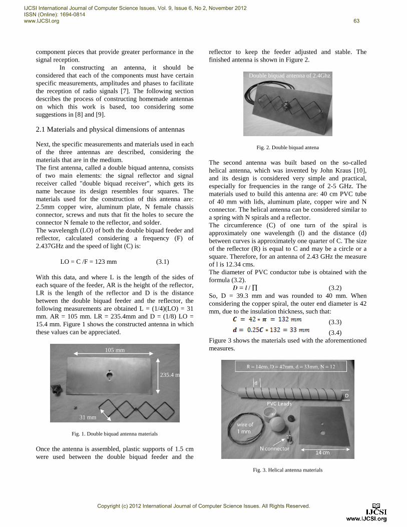
With this data, and where L is the length of the sides of each square of the feeder, AR is the height of the reflector, LR is the length of the reflector and D is the distance between the double biquad feeder and the reflector, the following measurements are obtained L = (1/4)(LO) = 31 mm. AR = 105 mm. LR = 235.4mm and D = (1/8) LO = 15.4 mm. Figure 1 shows the constructed antenna in which these values can be appreciated.
Fig. 1. Double biquad antenna materials
Once the antenna is assembled, plastic supports of 1.5 cm were used between the double biquad feeder and the
reflector to keep the feeder adjusted and stable. The finished antenna is shown in Figure 2.
Fig. 2. Double biquad antena
The second antenna was built based on the so-called helical antenna, which was invented by John Kraus [10], and its design is considered very simple and practical, especially for frequencies in the range of 2-5 GHz. The materials used to build this antenna are: 40 cm PVC tube of 40 mm with lids, aluminum plate, copper wire and N connector. The helical antenna can be considered similar to a spring with N spirals and a reflector. The circumference (C) of one turn of the spiral is approximately one wavelength (l) and the distance (d) between curves is approximately one quarter of C. The size of the reflector (R) is equal to C and may be a circle or a square. Therefore, for an antenna of 2.43 GHz the measure of l is 12.34 cms. The diameter of PVC conductor tube is obtained with the formula (3.2).
D = l / ∏ (3.2) So, D = 39.3 mm and was rounded to 40 mm. When considering the copper spiral, the outer end diameter is 42 mm, due to the insulation thickness, such that:
(3.3)
(3.4) Figure 3 shows the materials used with the aforementioned measures.
Fig. 3. Helical antenna materials
105 mm
235.4 mm
31 mm
Double biquad antenna of 2.4Ghz
IJCSI International Journal of Computer Science Issues, Vol. 9, Issue 6, No 2, November 2012 ISSN (Online): 1694-0814 www.IJCSI.org 63
Copyright (c) 2012 International Journal of Computer Science Issues. All Rights Reserved.
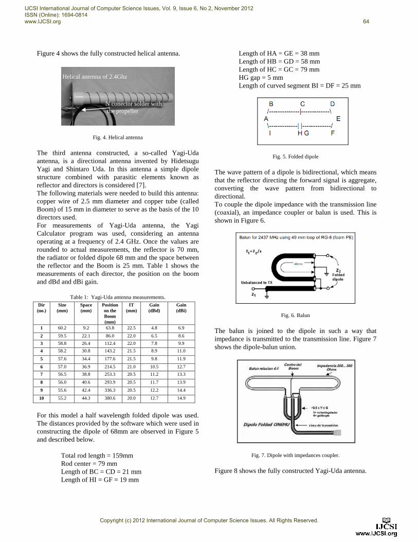
Figure 4 shows the fully constructed helical antenna.
Fig. 4. Helical antenna
The third antenna constructed, a so-called Yagi-Uda antenna, is a directional antenna invented by Hidetsugu Yagi and Shintaro Uda. In this antenna a simple dipole structure combined with parasitic elements known as reflector and directors is considered [7]. The following materials were needed to build this antenna: copper wire of 2.5 mm diameter and copper tube (called Boom) of 15 mm in diameter to serve as the basis of the 10 directors used. For measurements of Yagi-Uda antenna, the Yagi Calculator program was used, considering an antenna operating at a frequency of 2.4 GHz. Once the values are rounded to actual measurements, the reflector is 70 mm, the radiator or folded dipole 68 mm and the space between the reflector and the Boom is 25 mm. Table 1 shows the measurements of each director, the position on the boom and dBd and dBi gain.
Table 1: Yagi-Uda antenna measurements.
For this model a half wavelength folded dipole was used. The distances provided by the software which were used in constructing the dipole of 68mm are observed in Figure 5 and described below.
Total rod length = 159mm Rod center = 79 mm Length of BC = CD = 21 mm Length of HI = GF = 19 mm
Length of HA = GE = 38 mm Length of HB = GD = 58 mm Length of HC = GC = 79 mm HG gap = 5 mm Length of curved segment BI = DF = 25 mm
Fig. 5. Folded dipole
The wave pattern of a dipole is bidirectional, which means that the reflector directing the forward signal is aggregate, converting the wave pattern from bidirectional to directional. To couple the dipole impedance with the transmission line (coaxial), an impedance coupler or balun is used. This is shown in Figure 6.
Fig. 6. Balun
The balun is joined to the dipole in such a way that impedance is transmitted to the transmission line. Figure 7 shows the dipole-balun union.
Fig. 7. Dipole with impedances coupler.
Figure 8 shows the fully constructed Yagi-Uda antenna.
Dir (no.)
Size (mm)
Space (mm)
Position on the Boom (mm)
IT (mm)
Gain (dBd)
Gain (dBi)
1 60.2 9.2 63.8 22.5 4.8 6.9
2 59.5 22.1 86.0 22.0 6.5 8.6
3 58.8 26.4 112.4 22.0 7.8 9.9
4 58.2 30.8 143.2 21.5 8.9 11.0
5 57.6 34.4 177.6 21.5 9.8 11.9
6 57.0 36.9 214.5 21.0 10.5 12.7
7 56.5 38.8 253.3 20.5 11.2 13.3
8 56.0 40.6 293.9 20.5 11.7 13.9
9 55.6 42.4 336.3 20.5 12.2 14.4
10 55.2 44.3 380.6 20.0 12.7 14.9
N conector solder with the propeller
Helical antenna of 2.4Ghz
IJCSI International Journal of Computer Science Issues, Vol. 9, Issue 6, No 2, November 2012 ISSN (Online): 1694-0814 www.IJCSI.org 64
Copyright (c) 2012 International Journal of Computer Science Issues. All Rights Reserved.
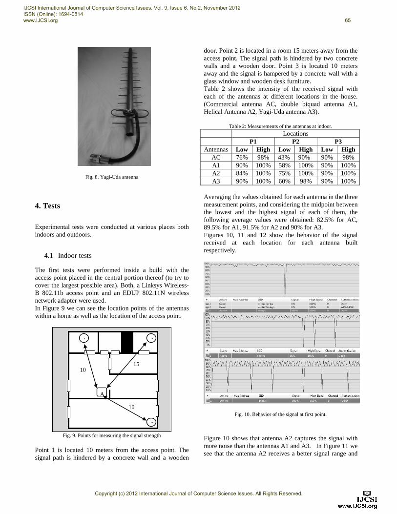
Fig. 8. Yagi-Uda antenna
4. Tests
Experimental tests were conducted at various places both indoors and outdoors.
4.1 Indoor tests
The first tests were performed inside a build with the access point placed in the central portion thereof (to try to cover the largest possible area). Both, a Linksys Wireless-B 802.11b access point and an EDUP 802.11N wireless network adapter were used. In Figure 9 we can see the location points of the antennas within a home as well as the location of the access point.
Fig. 9. Points for measuring the signal strength
Point 1 is located 10 meters from the access point. The signal path is hindered by a concrete wall and a wooden
door. Point 2 is located in a room 15 meters away from the access point. The signal path is hindered by two concrete walls and a wooden door. Point 3 is located 10 meters away and the signal is hampered by a concrete wall with a glass window and wooden desk furniture. Table 2 shows the intensity of the received signal with each of the antennas at different locations in the house. (Commercial antenna AC, double biquad antenna A1, Helical Antenna A2, Yagi-Uda antenna A3).
Table 2: Measurements of the antennas at indoor.
Locations P1 P2 P3
Antennas Low High Low High Low High AC 76% 98% 43% 90% 90% 98% A1 90% 100% 58% 100% 90% 100% A2 84% 100% 75% 100% 90% 100% A3 90% 100% 60% 98% 90% 100%
Averaging the values obtained for each antenna in the three measurement points, and considering the midpoint between the lowest and the highest signal of each of them, the following average values were obtained: 82.5% for AC, 89.5% for A1, 91.5% for A2 and 90% for A3. Figures 10, 11 and 12 show the behavior of the signal received at each location for each antenna built respectively.
Fig. 10. Behavior of the signal at first point.
Figure 10 shows that antenna A2 captures the signal with more noise than the antennas A1 and A3. In Figure 11 we see that the antenna A2 receives a better signal range and
1 2
3
10
15
10
A
IJCSI International Journal of Computer Science Issues, Vol. 9, Issue 6, No 2, November 2012 ISSN (Online): 1694-0814 www.IJCSI.org 65
Copyright (c) 2012 International Journal of Computer Science Issues. All Rights Reserved.
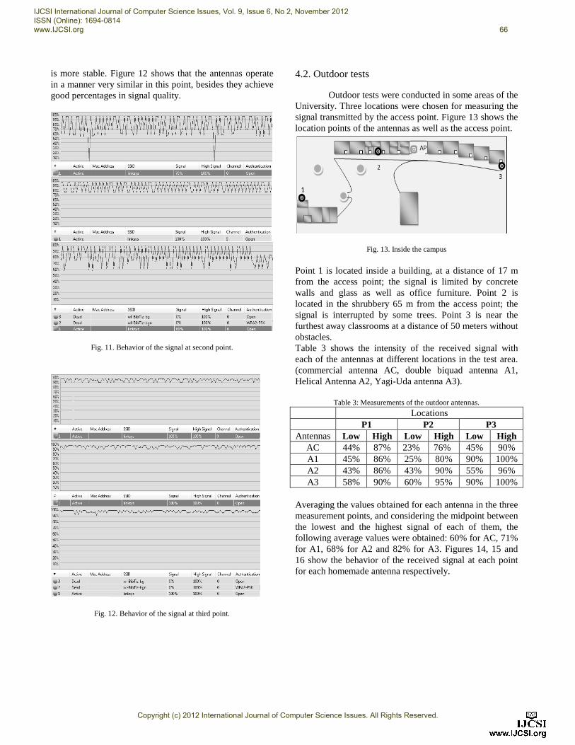
is more stable. Figure 12 shows that the antennas operate in a manner very similar in this point, besides they achieve good percentages in signal quality.
Fig. 11. Behavior of the signal at second point.
Fig. 12. Behavior of the signal at third point.
4.2. Outdoor tests
Outdoor tests were conducted in some areas of the University. Three locations were chosen for measuring the signal transmitted by the access point. Figure 13 shows the location points of the antennas as well as the access point.
Fig. 13. Inside the campus
Point 1 is located inside a building, at a distance of 17 m from the access point; the signal is limited by concrete walls and glass as well as office furniture. Point 2 is located in the shrubbery 65 m from the access point; the signal is interrupted by some trees. Point 3 is near the furthest away classrooms at a distance of 50 meters without obstacles. Table 3 shows the intensity of the received signal with each of the antennas at different locations in the test area. (commercial antenna AC, double biquad antenna A1, Helical Antenna A2, Yagi-Uda antenna A3).
Table 3: Measurements of the outdoor antennas.
Locations P1 P2 P3
Antennas Low High Low High Low High AC 44% 87% 23% 76% 45% 90% A1 45% 86% 25% 80% 90% 100% A2 43% 86% 43% 90% 55% 96% A3 58% 90% 60% 95% 90% 100%
Averaging the values obtained for each antenna in the three measurement points, and considering the midpoint between the lowest and the highest signal of each of them, the following average values were obtained: 60% for AC, 71% for A1, 68% for A2 and 82% for A3. Figures 14, 15 and 16 show the behavior of the received signal at each point for each homemade antenna respectively.
IJCSI International Journal of Computer Science Issues, Vol. 9, Issue 6, No 2, November 2012 ISSN (Online): 1694-0814 www.IJCSI.org 66
Copyright (c) 2012 International Journal of Computer Science Issues. All Rights Reserved.
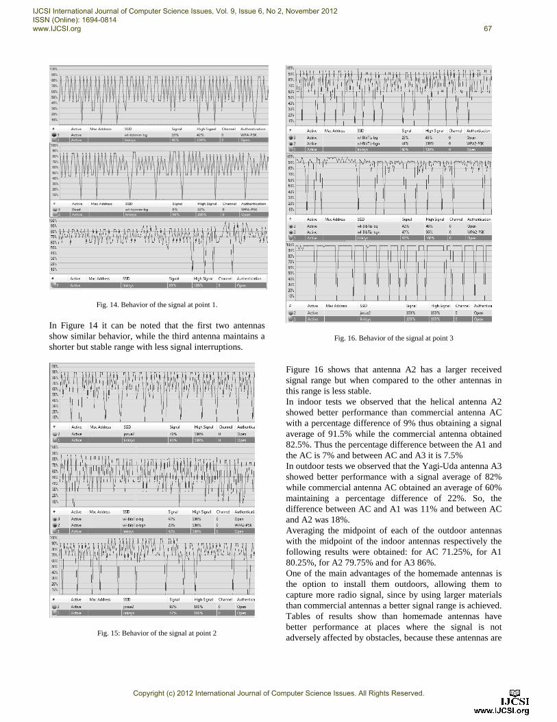
Fig. 14. Behavior of the signal at point 1.
In Figure 14 it can be noted that the first two antennas show similar behavior, while the third antenna maintains a shorter but stable range with less signal interruptions.
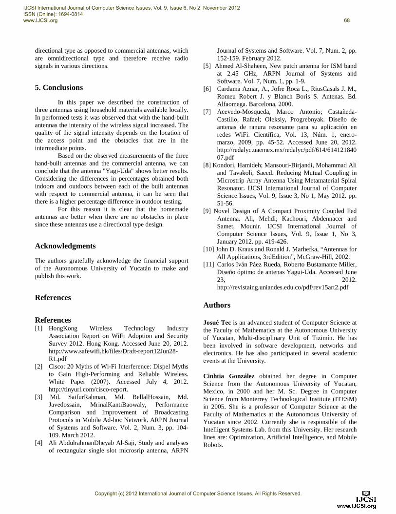
Fig. 15: Behavior of the signal at point 2
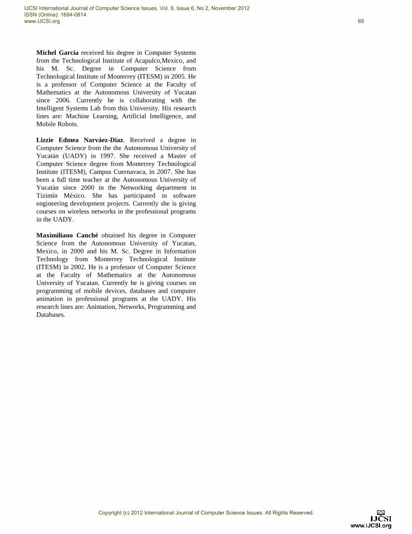
Fig. 16. Behavior of the signal at point 3
Figure 16 shows that antenna A2 has a larger received signal range but when compared to the other antennas in this range is less stable. In indoor tests we observed that the helical antenna A2 showed better performance than commercial antenna AC with a percentage difference of 9% thus obtaining a signal average of 91.5% while the commercial antenna obtained 82.5%. Thus the percentage difference between the A1 and the AC is 7% and between AC and A3 it is 7.5% In outdoor tests we observed that the Yagi-Uda antenna A3 showed better performance with a signal average of 82% while commercial antenna AC obtained an average of 60% maintaining a percentage difference of 22%. So, the difference between AC and A1 was 11% and between AC and A2 was 18%. Averaging the midpoint of each of the outdoor antennas with the midpoint of the indoor antennas respectively the following results were obtained: for AC 71.25%, for A1 80.25%, for A2 79.75% and for A3 86%. One of the main advantages of the homemade antennas is the option to install them outdoors, allowing them to capture more radio signal, since by using larger materials than commercial antennas a better signal range is achieved. Tables of results show than homemade antennas have better performance at places where the signal is not adversely affected by obstacles, because these antennas are
IJCSI International Journal of Computer Science Issues, Vol. 9, Issue 6, No 2, November 2012 ISSN (Online): 1694-0814 www.IJCSI.org 67
Copyright (c) 2012 International Journal of Computer Science Issues. All Rights Reserved.
directional type as opposed to commercial antennas, which are omnidirectional type and therefore receive radio signals in various directions.
5. Conclusions
In this paper we described the construction of three antennas using household materials available locally. In performed tests it was observed that with the hand-built antennas the intensity of the wireless signal increased. The quality of the signal intensity depends on the location of the access point and the obstacles that are in the intermediate points.
Based on the observed measurements of the three hand-built antennas and the commercial antenna, we can conclude that the antenna "Yagi-Uda" shows better results. Considering the differences in percentages obtained both indoors and outdoors between each of the built antennas with respect to commercial antenna, it can be seen that there is a higher percentage difference in outdoor testing.
For this reason it is clear that the homemade antennas are better when there are no obstacles in place since these antennas use a directional type design.
Acknowledgments
The authors gratefully acknowledge the financial support of the Autonomous University of Yucatán to make and publish this work.
References
References [1] HongKong Wireless Technology Industry
Association Report on WiFi Adoption and Security Survey 2012. Hong Kong. Accessed June 20, 2012. http://www.safewifi.hk/files/Draft-report12Jun28-R1.pdf
[2] Cisco: 20 Myths of Wi-Fi Interference: Dispel Myths to Gain High-Performing and Reliable Wireless. White Paper (2007). Accessed July 4, 2012. http://tinyurl.com/cisco-report.
[3] Md. SaifurRahman, Md. BellalHossain, Md. Javedossain, MrinalKantiBaowaly, Performance Comparison and Improvement of Broadcasting Protocols in Mobile Ad-hoc Network. ARPN Journal of Systems and Software. Vol. 2, Num. 3, pp. 104-109. March 2012.
[4] Ali AbdulrahmanDheyab Al-Saji, Study and analyses of rectangular single slot microsrip antenna, ARPN
Journal of Systems and Software. Vol. 7, Num. 2, pp. 152-159. February 2012.
[5] Ahmed Al-Shaheen, New patch antenna for ISM band at 2.45 GHz, ARPN Journal of Systems and Software. Vol. 7, Num. 1, pp. 1-9.
[6] Cardama Aznar, A., Jofre Roca L., RiusCasals J. M., Romeu Robert J. y Blanch Boris S. Antenas. Ed. Alfaomega. Barcelona, 2000.
[7] Acevedo-Mosqueda, Marco Antonio; Castañeda-Castillo, Rafael; Oleksiy, Progrebnyak. Diseño de antenas de ranura resonante para su aplicación en redes WiFi. Científica, Vol. 13, Núm. 1, enero-marzo, 2009, pp. 45-52. Accessed June 20, 2012. http://redalyc.uaemex.mx/redalyc/pdf/614/61412184007.pdf
[8] Kondori, Hamideh; Mansouri-Birjandi, Mohammad Ali and Tavakoli, Saeed. Reducing Mutual Coupling in Microstrip Array Antenna Using Metamaterial Spiral Resonator. IJCSI International Journal of Computer Science Issues, Vol. 9, Issue 3, No 1, May 2012. pp. 51-56.
[9] Novel Design of A Compact Proximity Coupled Fed Antenna. Ali, Mehdi; Kachouri, Abdennacer and Samet, Mounir. IJCSI International Journal of Computer Science Issues, Vol. 9, Issue 1, No 3, January 2012. pp. 419-426.
[10] John D. Kraus and Ronald J. Marhefka, “Antennas for All Applications, 3rdEdition”, McGraw-Hill, 2002.
[11] Carlos Iván Páez Rueda, Roberto Bustamante Miller, Diseño óptimo de antenas Yagui-Uda. Accessed June 23, 2012. http://revistaing.uniandes.edu.co/pdf/rev15art2.pdf
Authors Josué Tec is an advanced student of Computer Science at the Faculty of Mathematics at the Autonomous University of Yucatan, Multi-disciplinary Unit of Tizimín. He has been involved in software development, networks and electronics. He has also participated in several academic events at the University. Cinhtia González obtained her degree in Computer Science from the Autonomous University of Yucatan, Mexico, in 2000 and her M. Sc. Degree in Computer Science from Monterrey Technological Institute (ITESM) in 2005. She is a professor of Computer Science at the Faculty of Mathematics at the Autonomous University of Yucatan since 2002. Currently she is responsible of the Intelligent Systems Lab. from this University. Her research lines are: Optimization, Artificial Intelligence, and Mobile Robots.
IJCSI International Journal of Computer Science Issues, Vol. 9, Issue 6, No 2, November 2012 ISSN (Online): 1694-0814 www.IJCSI.org 68
Copyright (c) 2012 International Journal of Computer Science Issues. All Rights Reserved.
Michel García received his degree in Computer Systems from the Technological Institute of Acapulco,Mexico, and his M. Sc. Degree in Computer Science from Technological Institute of Monterrey (ITESM) in 2005. He is a professor of Computer Science at the Faculty of Mathematics at the Autonomous University of Yucatan since 2006. Currently he is collaborating with the Intelligent Systems Lab from this University. His research lines are: Machine Learning, Artificial Intelligence, and Mobile Robots. Lizzie Edmea Narváez-Díaz. Received a degree in Computer Science from the the Autonomous University of Yucatán (UADY) in 1997. She received a Master of Computer Science degree from Monterrey Technological Institute (ITESM), Campus Cuernavaca, in 2007. She has been a full time teacher at the Autonomous University of Yucatán since 2000 in the Networking department in Tizimín México. She has participated in software engineering development projects. Currently she is giving courses on wireless networks in the professional programs in the UADY. Maximiliano Canché obtained his degree in Computer Science from the Autonomous University of Yucatan, Mexico, in 2000 and his M. Sc. Degree in Information Technology from Monterrey Technological Institute (ITESM) in 2002. He is a professor of Computer Science at the Faculty of Mathematics at the Autonomous University of Yucatan. Currently he is giving courses on programming of mobile devices, databases and computer animation in professional programs at the UADY. His research lines are: Animation, Networks, Programming and Databases.
IJCSI International Journal of Computer Science Issues, Vol. 9, Issue 6, No 2, November 2012 ISSN (Online): 1694-0814 www.IJCSI.org 69
Copyright (c) 2012 International Journal of Computer Science Issues. All Rights Reserved.