hope creek, response to nrc request for …loi 3.d letter of intent loop 1 .a loss of offsite power...
TRANSCRIPT
PSEG Nuclear LLCP.O. Box 236, Hancocks Bridge, NJ 08038
0 PSEGNuclear LLC
10 CFR 50
JUN 0 1 201 10 CFR 5110 CFR 54
LR-N10-0181
U.S. Nuclear Regulatory CommissionATTN: Document Control DeskWashington, DC 20555
Hope Creek Generating StationFacility Operating License No. NPF-57NRC Docket No. 50-354
Subject: Response to NRC Request for Additional Information datedApril 20, 2010, related to the Severe Accident Mitigation Alternatives(SAMA) review associated with the Hope Creek Generating StationLicense Renewal Application
References: 1. Letter from Mr. Charles Eccleston (USNRC) to Mr. Thomas Joyce(PSEG Nuclear, LLC) "REQUEST FOR ADDITIONAL INFORMATIONREGARDING SEVERE ACCIDENT MITIGATION ALTERNATIVES FORHOPE CREEK GENERATING STATION", dated April 20, 2010
2. Letter from Mr. Charles Eccleston (USNRC) to Mr. Thomas Joyce(PSEG Nuclear, LLC) "REVISED REQUEST FOR ADDITIONALINFORMATION REGARDING SEVERE ACCIDENT MITIGATIONALTERNATIVES FOR HOPE CREEK GENERATING STATION", datedMay 20, 2010
In the Reference 1 letter, the staff requested additional information related to the SevereAccident Mitigation Alternatives (SAMA) analysis contained in the Hope CreekGenerating Station License Renewal Application (LRA). Reference 2 corrected someminor items related to the initial request. Enclosed are the responses to this request foradditional information.
This letter and its enclosure contain no commitments.
If you have any questions, please contact Ed Keating, Senior Environmental Advisor,PSEG Nuclear at 856-339-7902.

Document Control DeskLR-N10-0164 JUN 012010Page 2
I declare under penalty of perjury that the foregoing is true and correct.
Executed on: o I I '
Sincerely,
Paul J. DavisonVice President, Operations SupportPSEG Nuclear LLCEnclosure : Response to Request for Additional Information
cc: S. Collins, Regional Administrator - USNRC Region I (w/o enclosure)C. Eccleston, Environmental Project Manager, License Renewal - USNRC (w/enclosure)R. Ennis, Project Manager - USNRC (w/o enclosure)NRC Senior Resident Inspector - Salem (w/o enclosure)P. Mulligan, Manager IV, NJBNE (w/ enclosure)L. Marabella, Corporate Commitment Tracking Coordinator (w/o enclosure)Howard Berrick, Salem Commitment Tracking Coordinator (w/ enclosure)T. Devik, Hope Creek Commitment Tracking Coordinator (w/o enclosure)

EnclosureLR-N10-0181Page 1 of 144
ACRONYMS AND ABREVIATIONS
ACRONYM or RAI# DEFINITIONABREVIATION (1st use)
ABWR 5.n Advanced Boiling Water Reactor
AC 1 .b alternating current
ACP 1.d, Table ld-1 AC power
ACRS 1 .d, Table ld-1 Advisory Committee on Reactor Safeguards
ADHR 5.b alternate decay heat removal
ADS 5.a automatic depressurization system
AOV 5.i air operated valve
ASME 1 .b American Society of Mechanical Engineers
AST 4.d Alternate Source Term
ATWS 1 .b anticipated transient without scram
BE 1.d, Table ld-1 basic event
BOC 1 .b break outside containment
BWR 1.d, Table Id-1 boiling water reactor
BWROG 1 .d Boiling Water Reactor Owners' Group
CC 1 .d, Table ld-1 capability category.
CCDP 3.a conditional core damage probability
CCF 1 .b common cause failure
CDC 3.d certain dangerous cargo
CDF 1.a core damage frequency
CET 2.a containment event tree
CFR 3.d Code of Federal Regulations
CHR 5.b, Table 5b-1 containment heat removal
COTP 3.d Captain of the Port
CRD 1.d, Table 1d'1 control rod drive
CS 1 .d, Table ld-1 containment spray
CSC 1 .b containment spray cooling
CSS 5.b core spray system
CV 1 .d, Table 1 d-1 control valve
DAEC 5.r Duane Arnold Energy Center
I

EnclosureLR-N10-0181Page 2 of 144
ACRONYMS AND ABREVIATIONS
ACRONYM or RAI# DEFINITIONABREVIATION (1st use)
DC 1 .b direct current
DE 4.a Delaware
DG 3.a diesel generator (same as DGN)
E 4.a east
EAL 2.a emergency action level
ECCS 6.i emergency core cooling system
EDG 1 .b emergency diesel generator
EIA 5.a emergency instrument air
ENE 4.a east-north-east
EOP 1 .d, Table id-1 emergency operating procedure
EPRI 1.b Electric Power Research Institute
ER 5.j [license renewal] environmental report
ESE 4.a east-south-east
ESF 1 .d, Table id-1 engineered safety features
F&Os 1 .d facts and observations
FERC 3.d Federal Energy Regulatory Commission
FPIE 1 .f full power, internal events
FPS 1 .d, Table id-1 fire protection system
F-V 1.e Fussell-Vesely
FW 1 .d, Table ild-1 feed water
GE 1 .d General Electric Company
GTG 6.c gas turbine generator
HCGS 1.a Hope Creek Generating Station
HCLPF 5.j High Confidence, Low Probability of Failure
HCTL 6.i heat capacity temperature limit
HEP 1 .b human error probability
HFE 1 .d, Table id-1 human failure event
HPCI 1 .b high pressure coolant injection
HRA 1 .b human reliability analysis
I

EnclosureLR-N10-0181Page 3 of 144
ACRONYMS AND ABREVIATIONS
ACRONYM or RAI # DEFINITIONABREVIATION (11t use)
HRS 5.p, Table 5.p-1 hours
HVAC 1 .d, Table id-1 heating, ventilation and air conditioning
HX 1 .b heat exchanger
IE 1.d, Table ld-1 initiating event
IMO 3.d International Maritime Organization
IPE 1 .a individual plant examination
IPEEE 3.a individual plant examination of external events
K 6.b thousand
kV 1 .d, Table ld-1 kilovolts
LERF 1 .d, Table id-1 large, early release fraction [or frequency]
LLC 3.d Limited Liability Company
LLNL 3.c Lawrence Livermore National Laboratory
LNG 3.d liquefied natural gas
LOCA 1 .d, Table ld-1 loss of coolant accident
LOI 3.d Letter of Intent
LOOP 1 .a loss of offsite power
LOR 3.d Letter of Recommendation
LPCI 2.b low pressure coolant injection
LRA 6.a License Renewal Application
M 6.b million
m3 3.d cubic meters
MAAP 1 .d, Table ld-1 Modular Accident Analysis Program
MELCOR Accident Consequence Code System for the CalculationMACCS2 2.b of the Health and Economic Consequences of Accidental
Atmospheric Radiological Releases
MACR 5.j maximum averted cost risk
MCCs 1 .d, Table 1 d-1 motor control centers
MCR 5.1 main control room
MD 4.a Maryland
MOV i .d, Table id-1 motor operated valve

EnclosureLR-N10-0181Page 4 of 144
ACRONYMS AND ABREVIATIONS
ACRONYM or RAI# DEFINITIONABREVIATION (1 st use)
MSIV 5.j main steam isolation valve
MSPI 1 .d, Table id-1 mitigating systems performance index
N 4.a north
NE 4.a north-east
NEI 1 .d Nuclear Energy Institute
NEMA 5.g National Electrical Manufacturers Association
NJ 3.d New Jersey
NNE 4.a north-north-east
NNW 4.a north-north-west
NW 4.a north-west
OECR 4.a offsite economic cost risk
PA 4.a Pennsylvania
PACR 5.j partial averted cost risk
PCIG 1 .d, Table ld-1 primary containment instrument gas
PCS 5.p, Table 5.p-1 primary cooling system
PDR 4.a population dose risk
PHC 8 Plant Health Committee
PRA 1 .a probabalistic risk assessment
PSA 1 .d, Table id-1 probabilistic safety assessment
PSF 1.d, Table ld-1 performance shaping factor
QU 1 .d, Table 1 d-1 quantification
RACS 1 .d, Table 1 d-1 reactor auxiliaries cooling system
RAI 2.a . request for additional information
RAW 1 .d, Table ld-1 risk achievement worth
RCIC 1 .b reactor core isolation cooling
RCS 5.p, Table 5.p-1 reactor coolant system
RHR 1 .b residual heat removal
RM 1 .f risk management

EnclosureLR-N1 0-0181Page 5 of 144
ACRONYMS AND ABREVIATIONS
ACRONYM or RAI# DEFINITIONABREVIATION (1 st use)
RPS 5.p, Table 5.p-1 reactor protection system
RPV 1 .b reactor pressure vessel
RRW 5.j risk reduction worth
RX 6.i reactor
S 4.a south
SACS 1.a safety auxiliaries cooling system
SAG 2.a severe accident guideline
SAMA 1.a severe accident mitigation alternative
SAMG 5.d Severe Accident Management Guidance
SBO 1 .b station blackout
SDC 1 .b shutdown cooling
SE 4.a south-east
SI 1.d, Table ld-1 special initiator
SLC 5.r standby liquid control
SOLAS 3.d International Convention for the Safety of Life at Sea
SOV 5.o solenoid-operated valve
SPC 1 .b suppression pool cooling
SRs 1 .d supporting requirements
SRV 2.b safety relief valve
SSC 1 .d, Table ld-1 structures, systems, and components
SSE 4.a south-south-east
SSW 1 .d, Table ld-1 standby service water
SSW 4.a south-south-west
SSWS 1.a station service water system
SW 5.o service water
SW 4.a south-west
SWGR 5. a switchgear
TAF 5.a top of active fuel
TDP 5.p, Table 5.p-1 turbine-driven pump
TM 5.p, Table 5.p-1 test and maintenance
TMI 5.i Three Mile Island Generating StationI

EnclosureLR-N10-0181Page 6 of 144
ACRONYMS AND ABREVIATIONS
ACRONYM or RAI# DEFINITIONABREVIATION (1 st use)
TSC 1 .b technical support center
URE 1.e updates requirement evaluation
V AC 1 .b volts alternating current
VDC 1 .d, Table ld-1 volts direct current
W 4.a west
W/IN 5.p, Table 5.p-1 within
WNW 4.a west-north-west
WSW 4.a west-south-west

EnclosureLR-N10-0181Page 7 of 144
RESPONSES TO REQUESTS FOR ADDITIONAL INFORMATION (RAIs)
Provide the following information regarding the Probabilistic Risk Assessment (PRA)used for the Severe Accident Mitigation Alternative (SAMA) analysis:
1.a Provide a brief summary of the most significant changes made to the individualplant examination (IPE) to obtain PRA Model 0.
PSEG Response:
Based on the changes incorporated into the IPE to create PRA Model 0, the CDFdecreased from 4.59E-5/yr to 1.29E-5/yr. The significant model changesincorporated into the IPE to create PRA Model 0 included the following:
* Credit is taken for Beyond Design Basis Safety Auxiliaries Cooling System(SACS) and Station Service Water System (SSWS) Success Criteria. Whenthe HCGS IPE was assembled, there had been no analysis that would allowtaking credit for the operation of the SACS and SSWS systems beyond theirdesign basis (i.e., success criteria of two out of two pumps per loop).However, as new calculations were performed, it was found that each SSWSloop could perform its function with one out of two pumps operating. It wasalso found that each SACS loop could perform its function with one pump outof two operating, on the conditions that at least one pump be operating in theopposite SACS loop and that reactor operators are successful in manipulatingSACS loads to allow the operation.
* The total CDF decreased from 4.59E-5/yr in the IPE to 1.29E-5/yr in PRAModel 0. The most significant impact the SACS/SSWS success criteria hadwas on the LOOP initiated core damage sequences. The CDF contribution ofLOOP sequences decreased from 3.38E-5/yr to 2.33E-6/yr when credit wasgiven to full capacity operation of the SACS and SSWS. The CDF contributionof loss of decay heat removal sequences was also significantly reduced,decreasing from 5.45E-7/yr to 7.28E-8/yr. However, this represented a verysmall change in total CDF.
* The SACS and SSWS success criteria assumptions were the major significantchanges to the PRA models after the completion of the HCGS IPE to obtainPRA Model 0. Other minor model changes had a negligible impact on CDF.

EnclosureLR-N10-0181Page 8 of 144
1 .b Sections E.2.1.3, E.2.1.4, E.2.1.5, E.2.1.9 and E.2.1.10 provide very detaileddescriptions of the changes made to the various Hope Creek Generating Station(HCGS) revisions. Since Models 1.1, 1.2 and 1.3 were described as minorrevisions, identify which of the model changes listed in Sections E.2.1.3 throughE.2.1.5 most impacted the change in core damage frequency (CDF) from Model1.0 to Model 1.3. For Models 108A and 108B, identify the model changes listedin Sections E.2.1.9 and E.2.1.10 that most impacted the change in CDF.
PSEG Response:
Based on the modifications incorporated into PRA Model 1.0 to create PRAModel 1.1, the CDF decreased from 1.80E-5/yr to 1.05E-5/yr. Based on thelisting in Section E.2.1.3, the changes with the most impact on CDF included thefollowing:
NR-SACS-SHED-01 (Failure to Operate with one SACS Pump) - Human errorrecovery event NR-SACS-SHED-01 is requantified. This operator actioninvolved failure to shed SACS system heat loads in order to reduce thenumber of SACS pumps and heat exchangers required for successful accidentmitigation. Reducing the number of SACS pumps and heat exchangersrequired for success increases the availability of front line systems (e.g., EDGroom cooling and RHR HX cooling).
" NR-RHR-INIT (Failure to Initiate RHR for Suppression Pool Cooling) - Humanerror recovery event NR-RHR-INIT is requantified. Manual initiation of RHR inthe SPC mode is a primary mitigation system for containment heat removal.Operator action NR-RHR-INIT was initially assigned a human error probabilityof 2.OE-04. The post-accident human error NR-RHR-INIT is also modeled tofail RHR in the Shutdown Cooling mode (SDC) and the Containment Spraymode (CSC). For each of these independent actions (SDC and CSC) thevalue of 0.1 from the NUREG/CR-1278 Chapter 20 is assigned for each action.This results in a total HEP of 2.OE-04 *0.1 *0.1 = 2.OE-06 to fail all modes ofRHR for decay heat removal. To account for potential dependent operatoractions for other means of containment heat, operator action NR-RHR-INITwas used to replace operator action NR-VENT-5 (Failure to Vent Containment)in the Containment Venting fault tree logic.
* The Disallow maintenance fault tree was revised to include mutually exclusiveevents such as two SACS pumps in maintenance or two SSWS pumps inmaintenance. Cutsets with multiple trains in maintenance overestimated theCDF because this maintenance combination does not reflect the normalmaintenance practices of the plant,. Maintenance configuration is controlledby plant procedures and Technical Specifications.
Based on the changes incorporated to create PRA Model 1.2, the CDFdecreased from 1.05E-5/yr to 8.70E-6/yr. Based on the listing in Section E.2.1.4,the changes with the most impact on CDF included the following:
* Enhanced common cause failure (CCF) analysis to include the following:

EnclosureLR-N10-0181Page 9 of 144
o Added basic events for CCF to Start and CCF to Run for combinations ofthree of four SACS pumps.
o Added separate CCF events for CCF of the HPCI and RCIC suctionstrainers and CCF of the RHR and Core Spray suction strainers.
o Updated various other CCF probabilities due to changes in theirindependent failure probabilities or due to changes in their associatedCCF grouping sizes.
* Eliminated the dependency of Core Spray room cooling on SACS coolingbased on a review of room heat up calculations. This model modificationdecreased CDF because loss of SACS alone does not lead to loss of all RPVmakeup.
* Added initiating events, event trees, and system mitigation logic associatedwith Steam/Water line Break Outside Containment (BOC) and ManualShutdown events.
" Significantly updated the ATWS sequence and system mitigation logic.
Based on the changes incorporated to create PRA Model 1.3, the CDFdecreased from 8.70E-6/yr to 8.66E-6/yr. Based on the listing in Section E.2.1.5,the changes with the most impact on CDF included the following:
" Enhanced SACS success criteria. Specifically, the SACS success criteria wasmodified to include the following:
o Failure of one SACS pump and one heat exchanger in one loop, withanother SACS pump failure in another loop, with operator failure to re-align the valves.
o Failure of one SACS pump and one heat exchanger in one loop, with oneheat exchanger failure in another loop.
" The SACS initiating event fault tree was modified to be failure of three out offour SACS trains. Similar changes were incorporated for the SACS systemmitigation fault tree.
Based on the changes incorporated to create PRA Model 108A, the CDFdecreased from 9.76E-6/yr to 7.60E-6/yr. Based on the listing in Section E.2.1.9,the changes with the most impact on CDF included the following:
* Included SACS and SSWS seasonal success criteria. The relaxedrequirements for SACS and SSWS cooling to support accident mitigation (e.g.,EDG room cooling and RHR HX cooling) during the colder months reduced theCDF.
* Included updated internal flooding model scenarios and flooding initiatingevent frequencies. The internal flooding PRA was updated and quantified tobe consistent with the ASME PRA Standard requirements. The internalflooding initiating event frequencies were developed using the latest EPRI

EnclosureLR-N10-0181
Page 10 of 144
guidance based on industry operating experience. The updated internalflooding model increased the CDF.
* Included portable battery charger to extend DC power supply during StationBlackout scenarios. The HC108A model credited the Technical SupportCenter (TSC) procedure for aligning the portable battery charger during SBOscenarios. Extending the DC power supply for accident mitigation increasedthe probability for offsite AC power recovery and reduced the CDF.
* Reassessed the independent human error probabilities (HEPs) using the latestoperating crew interviews and the EPRI HRA Calculator. Some HEPsincreased and others decreased. The overall impact of the updatedindependent HEPs reduced the CDF.
* Updated quantitative evaluation of dependent operator actions. Includingadditional dependent operator action basic events and updating existing jointhuman error probabilities in the model increased the CDF.
Based on the changes incorporated to create PRA Model 108B, the CDFdecreased from 7.60E-6/yr to 5.11E-6/yr. Based on the listing in SectionE.2.1.10, the changes with the most impact on CDF included the following:
" Credited procedure change to allow local manipulation of SSWS to SACS heatexchanger valves under LOOP conditions. The ability to locally open theSSWS to SACS heat exchanger valves credits additional success paths foraccident mitigation (e.g., EDG room cooling and RHR HX cooling). Thisprocedure change reduced the CDF.
* Updated modeling of 120 VAC inverter room cooling logic to support HPCI andRCIC operation. Updated logic removed conservatism in the model andreduced the CDF.
• Updated the SACS pump Fail to Start and Fail to Run probabilities in the PRAbasic event database to be consistent with the Bayesian update values in thePRA documentation. The updated SACS pump data reduced the CDF.
1 .c Provide the contribution to the internal event CDF due to anticipated transients
without scram (ATWS) and due to station blackout (SBO).
PSEG Response:
For the Hope Creek HC108B model, the ATWS contribution to Level 1 CDF isapproximately 1.6E-7/yr, or approximately 3% of the total Level 1 CDF of.5.11E-6/yr (when using a truncation level of 1E-12/yr). The SBO contribution toLevel 1 CDF is approximately 6.OE-7/yr, or approximately 12% of the total Level1 CDF of 5.11 E-6/yr.

EnclosureLR-N10-0181
Page 11 of 144
1 .d Provide additional information on the 2008 peer review including the compositionof the review team, and the status and impact on the SAMA analysis of thesupporting requirements that only met Capability Category I. Describe any otherinternal and external reviews of the Level 1 (including internal flooding) and Level2 PRA model, significant review comments and their resolution, and the impact ofunresolved comments on the results of the SAMA analysis.
PSEG Response:
The Hope Creek 2008 PRA Peer Review was conducted in accordance with NEI05-04, "Process for Performing Follow-on PRA Peer Reviews Using the ASMEPRA Standard, Nuclear Energy Institute". This document defines the reviewprocess used in the BWROG industry peer previews. Consistent with NEI 05-04guidance, the PRA Peer Review team consisted of six (6) members withappropriate and diverse nuclear and PRA experience. The team consisted ofone (1) contractor consultant, one (1) GE representative, and four (4) utility PRArepresentatives. Section 6 of the ASME PRA Standard also provides guidanceregarding review team member independence with respect to the PRA underreview. The Hope Creek peer review team satisfied the requirements of theASME PRA Standard and did not include any members who were involved in theperformance or preparation of the Hope Creek PRA.
Table ld-1 provides the following information relative to the Hope Creek 2008PRA Peer Review:
* A summary of the ASME PRA Standard Supporting Requirements (SRs) thatdid not meet Capability Category II based on a review of the HC108A PRAmodel.
* A summary of the PRA Peer Review Finding-level Facts and Observations(F&Os).
" The current status of the identified SRs and Findings relative to the updatedHC1 08B PRA model used as input to the SAMA evaluation.
* The impact of unresolved gaps to the ASME PRA Standard or Findings on theresults of the SAMA analysis.

EnclosureLR-N10-0181
Page 12 of 144
Table ld-1
OPEN GAPS AND FINDINGS FROM HCGS OCTOBER 2008 PEER REVIEW (HC108A PRA MODEL)
Supporting Peer Review ApplicableSuprting Capability Findings & Basis for Assessment Status and Impact on SAMA EvaluationRequirement Assessment Suggestions
System matrix used to perform IE Finding resolved as part of HC108B PRA Update.assessment. System-by-system review was Capability Category re-assessed as SR MET: (CCperformed and documented in Section 2.4.12 II). Therefore, this issue does not impact the abilityof the IE notebook (HC PSA-001, Rev 1) for to perform the SAMA evaluation.evaluation of potential special initiators (Sis) The HCGS PRA explicitly models the initiatorsthat result in trip or shutdown and degrade a associated with the following:mitigating or support system. Each plantsystem is listed on a system level basis in Loss of SSW %IE-SWSTable 2.4-0, but no qualitative review or Loss of SACS %IE-SACSstructured evaluation of impacts is provided Loss of PCIG %IE-IASas to why a system was or was not screenedas a SI. Subsequent evaluation of those The loss of HVAC is explicitly screened out usingsystems designated as SI considers the the screening criterion IE-C4(c). The basis for this
SR MET: IE-A4-01 systems on a train basis. For some systems is the room heat up calculations provided in theIE-A4 (CC 1) (Finding) (SSW, SACS, PCIG, some HVAC, etc.) loss Dependency Notebook which show the times to
of the system or a single loop or train is heat up critical areas is tens of hours andscreened out per criterion (c) in SR IE-C4 proceduralized guidance is available for alternatealthough no supporting calculations are cooling.referenced showing there is sufficient time todetect and correct the IE conditions before Therefore, the IE-C4(c) screening criteria is met fornormal plant operation is curtailed. FINDING: the HVAC initiator and the other cited initiators areNo structured evaluation of impacts from not screened out.individual system or train failures to assess For lower voltage buses, MCCs, or panels, thesethe possibility for an IE. Do not consider failures are subsumed into the higher voltage or thebuses other than 4kV and 125VDC. No bus with higher impacts.supporting calculations (per IE-C4) to show The special initiator list has been compared withthere is sufficient time to detect and correct other comparable BWRs, and there is no evidencepotential IE conditions before normal plant that any Special Initiators (SI) were missed.operation must be curtailed.

EnclosureLR-N10-0181
Page 13 of 144
Table id-1
OPEN GAPS AND FINDINGS FROM HCGS OCTOBER 2008 PEER REVIEW (HC108A PRA MODEL)S Ing Peer Review Applicable
Supporting Capability Findings & Basis for Assessment Status and Impact on SAMA EvaluationRequirement Assessment Suggestions
IE-A6 SR MET:(CC1)
IE-A6-01(Finding)
Section 2.1 of the IE notebook (HC PSA-001,Rev 1) notes that interviews were conductedwith operations and engineering personnel forprecursors, possible plant-unique lEs, andconfirmation of the lEs derived from themaster logic diagram. However, there is nodocumentation or detailed reference in the IEnotebook on these interviews (personsinvolved, dates, specific topics discussed,insights, etc.) Appendix I is referencedregarding the precursors, but there are nodetails on interviews within that appendix.The HRA notebook is also referenced,although Section 2.6 and Appendix Fdescribe only interviews regarding the EOPs,PSFs, training, response time, etc.; where itwas noted that the loss of a single 7.2kV busdoes not cause a Reactor Scram based onoperations interviews (February 2003).Finally, the system notebooks are alsomentioned, but a review of the interviewdocumentation in the AC and SSW notebooksshows essentially a duplication of the IEassessment included in the IE notebook.There is no indication of any insights,clarifications, or confirmations provided by thesystem manager. FINDING: No details areprovided regarding interviews conducted withoperations and engineering personnel toidentify precursors, possible plant-unique lEs,and confirmation of the lEs derived from themaster logic diagram.
Finding resolved as part of HC108B PRA Update.Capability Category re-assessed as SR MET: (CCII). Therefore, this issue does not impact the abilityto perform the SAMA evaluation.
The Initiating Event Notebook includes the resultsof the systematic process for determining initiatingevents including the results of both interviewprocesses.
Subsequent to the Peer Review in October 2008,the System Managers that were interviewedconfirmed the interview results.
EnclosureLR-N10-0181
Page 14 of 144
Table ld-1
OPEN GAPS AND FINDINGS FROM HCGS OCTOBER 2008 PEER REVIEW (HC108A PRA MODEL)
Supporting Peer Review ApplicableSuprting Capability Findings & Basis for Assessment Status and Impact on SAMA EvaluationRASuirementAssessment Suggestions
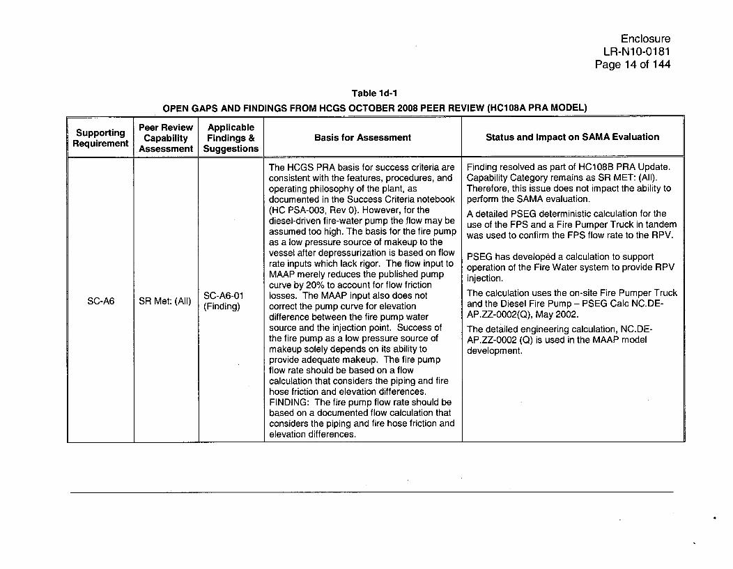
SC-A6 SR Met: (All)SC-A6-01(Finding)
The HCGS PRA basis for success criteria areconsistent with the features, procedures, andoperating philosophy of the plant, asdocumented in the Success Criteria notebook(HC PSA-003, Rev 0). However, for thediesel-driven fire-water pump the flow may beassumed too high. The basis for the fire pumpas a low pressure source of makeup to thevessel after depressurization is based on flowrate inputs which lack rigor. The flow input toMAAP merely reduces the published pumpcurve by 20% to account for flow frictionlosses. The MAAP input also does notcorrect the pump curve for elevationdifference between the fire pump watersource and the injection point. Success ofthe fire pump as a low pressure source ofmakeup solely depends on its ability toprovide adequate makeup. The fire pumpflow rate should be based on a flowcalculation that considers the piping and firehose friction and elevation differences.FINDING: The fire pump flow rate should bebased on a documented flow calculation thatconsiders the piping and fire hose friction andelevation differences.
Finding resolved as part of HC108B PRA Update.Capability Category remains as SR MET: (All).Therefore, this issue does not impact the ability toperform the SAMA evaluation.
A detailed PSEG deterministic calculation for theuse of the FPS and a Fire Pumper Truck in tandemwas used to confirm the FPS flow rate to the RPV.
PSEG has developed a calculation to supportoperation of the Fire Water system to provide RPVinjection.
The calculation uses the on-site Fire Pumper Truckand the Diesel Fire Pump - PSEG Calc NC.DE-AP.ZZ-0002(Q), May 2002.
The detailed engineering calculation, NC.DE-AP.ZZ-0002 (Q) is used in the MAAP modeldevelopment.

EnclosureLR-N10-0181
Page 15 of 144
Table ld-1
OPEN GAPS AND FINDINGS FROM HCGS OCTOBER 2008 PEER REVIEW (HC108A PRA MODEL)
Supporting Peer Review ApplicableSuprting Capability Findings & Basis for Assessment Status and Impact on SAMA EvaluationRequirement Assessment Suggestions
The interview seems to be a replication of the Suggestion resolved as part of HC108B PRAprevious text of the system notebook. There Update. Capability Category re-assessed as SRis no evidence of feedback from the MET: (CC Il/111). Therefore, this issue does notinterviewee. The walkdowns are to confirm impact the ability to perform the SAMA evaluation.that the systems analysis is correct. Theresults of the system walkdowns are merely Subsequent to the Peer Review, the System
SY-A2 SR Not Met (Suggestion) summed up as being captured in the system Managers that were interviewed confirmed theevaluation models. This does not meet the finterview results.intent of the walkdowns.
The Internal Flood Walkdown Notebook is the mostrecent documented PRA walkdown and itaddresses the spatial influences that may affectsystems (primarily flood related).
System components and boundaries are The Finding remains OPEN. This gap remains astypically not defined in the system notebooks SR Not Met.but referred to the Component Data As noted in the finding, the component informationNotebook. This is acceptable for components is present in the documentation of the Componentbut the system boundaries should be defined Data Notebook. In addition, the system boundaryin the system notebook. has been drafted for each system notebook but not
sY-A6 SR Not Met SY-A3-01 FINDING - The information provided is yet included in the published system notebooks. A(Finding) incomplete such that the SR is not met. review of these system boundaries reveals no
impact on the conclusions of the SAMA riskassessment.
Therefore, this is a documentation issue notaffecting the ability to perform the SAMA riskevaluation.

EnclosureLR-N10-0181
Page 16 of 144
Table id-1
OPEN GAPS AND FINDINGS FROM HCGS OCTOBER 2008 PEER REVIEW (HC108A PRA MODEL)
Supporting Peer Review ApplicableR Capability Findings & Basis for Assessment Status and Impact on SAMA EvaluationRASuirementAssessment Suggestions
The standard requires that failure of commonpiping be modeled if the failure affects morethan one system. The common piping failurebetween HPCI/FW/CS and RCIC/FW havenot been modeled.
SY-B14 SR Not MetSY-B1i4-01(Finding)
Finding resolved as part of HC108B PRA Update.Capability Category re-assessed as SR MET: (All).Therefore, this issue does not impact the ability toperform the SAMA evaluation.
The treatment of the common pipe between thefollowing could influence PRA modeling:
- RCIC and FW- HPCI and FW- HPCI and CS
For HPCI evaluations, because of the multiplepaths into the RPV from HPCI, breaks in the FW orCS pipe do not compromise the ability for HPCI toprovide adequate makeup to meet the PRAsuccess criteria. All common valve failures (e.g.,MOVs and CVs) between HPCI/CS A andHPCI/FW A are explicitly modeled to fail thecommon systems.
Unisolable breaks outside containment are treatedto fail all RPV injection sources in the ReactorBuilding. Therefore, no additional dependencytreatment is needed for those cases.
This represents a single example of possiblecommon pipe rupture effects. It does not represent"a systematic failure to address the requirement".
This model modification has been evaluated andassessed as a negligible impact on the PRA riskmetrics. No other instances of screening common

EnclosureLR-N10-0181
Page 17 of 144
Table id-1
OPEN GAPS AND FINDINGS FROM HCGS OCTOBER 2008 PEER REVIEW (HC108A PRA MODEL)
Supporting Peer Review Applicableuppomng Capability Findings & Basis for Assessment Status and Impact on SAMA Evaluation
Requirement Assessment Suggestions
_ I _ I components for multiple systems are identified.
SY-C2 SR Met: (All)SY-C2-01(Finding)
The documentation present in the systemnotebooks largely addresses the suggestedtopics from this SR. However, there areseveral recommendations for improving thedocumentation:1. Section 4.4, Dependency Matrix, shouldhave a legend detailing what A and Brepresent, this was seen in the CRD notebook
2. Section 2.10 has generic spatialdependencies for CRD. For CS it states "Nospatial dependencies other than thoseimposed by room cooling, internal flooding,and LOCA harsh environment." No details areprovided. No details are provided on roomlocation for the CRD and CS notebooks.3. System walkdown checklists should beused to address the topics in SY-C2. Thereare system walkdown checklists for theflooding but the questions and focus are notthe same as required in SY-C2.4. If only going to list the basic events in theQuantification Notebook there should be ties ineach System notebook going to the respectivesystems.
FINDING -The information provided isincomplete such that the SR is not fully met;the information provided must be more readily
This Finding remains OPEN. Capability Categoryremains as SR MET: (All). The SupportingRequirement SY-C2 was assessed as SR Met (All)in the peer review assessment, however, a findingwas identified.
This is a documentation finding not affecting theability to perform the SAMA risk assessment. Eachspecific item in the finding was reviewed and wouldnot impact the conclusions of the SAMA riskassessment.

EnclosureLR-N10-0181
Page 18 of 144
Table id-1
OPEN GAPS AND FINDINGS FROM HCGS OCTOBER 2008 PEER REVIEW (HC108A PRA MODEL)
Supporting Peer Review Applicable
Requirement Capability Findings & Basis for Assessment Status and Impact on SAMA EvaluationR Assessment Suggestions
defensible & traceable.
Tables 4.3-4 and 4.3-5 of the HRA Notebook Finding resolved as part of HC108B PRA Update.(HC PSA-004, Rev. 0) present the defined Capability Category re-assessed as SR MET: (CCrestoration and miscalibration Type A HFEs. Il/111). Therefore, this issue does not impact theThe restoration errors include failure to ability to perform the SAMA evaluation.restore a system, train or component to The requested peer review actions were screenedoperable status. The calibration errors include from consideration using HR-B1, and therefore, aremiscalibration for signals for equipment not applicable for HR-C2.realignment or startup (undervoltage, dieselfuel refill, ESF actuation, SACS/RACStemperature control, ventilation control).Additional information provided by PSEG
SR MET: HR-C2-01 regarding additional errors (e.g., restoration of(CC I) (Finding) power supply) referred only to the ACP
events in Tables 4.3-4 and 4.3-5. However,these pertain only to bus voltage sensors forundervoltage transfers and restoration of thegas turbine. FINDING: In addition torestoration errors for bus voltage sensors forundervoltage transfers and restoration of thegas turbine, also consider errors forrestoration of power supply to specificcomponents and other failure modesidentified during the steps described in SRsHR-A1/A2.

EnclosureLR-N1\0-0181
Page 19 of 144
Table ild-1
OPEN GAPS AND FINDINGS FROM HCGS OCTOBER 2008 PEER REVIEW (HC108A PRA MODEL)
Supporting Peer Review ApplicableRuirement Capability Findings & Basis for Assessment Status and Impact on SAMA Evaluation____n Assessment Suggestions
Other than a general statement regarding the Finding resolved as part of HC108B PRA Update.high quality of procedures at HCGS, no Capability Category re-assessed as SR MET: (CCevidence was seen that the quality of Il/111). Therefore, this issue does not impact theprocedures, administrative controls or human- ability to perform the SAMA evaluation.machine interface were evaluated for the pre- The quality of the Hope Creek procedures and theinitiator HEPs. human-machine interface were both evaluated as
HR-D3 SR MET: HR-D3-01 FINDING: Need discussion showing part of the pre-initiator HEP assessment. Both of(CC I) (Finding) consideration of the quality of written these aspects were found by the HRA analysts to
procedures, administrative controls, and the be above the quality level typically found for BWRs.human-machine interface, and the impact of Sections 3.0.4 and 3.0.13 of the HRA Notebookthat quality when evaluating pre-initiator explicitly address this issue and are used toHEPs. establish and document the basis for assessing the
quality of the PSEG and HCGS proceduralguidance.
The HCGS Component Data Book, Appendix This Finding remains OPEN. Capability CategoryC (HC PSA-010, Rev. 1), documents the remains as SR MET: (CC I).plant-specific unavailability/failure probability The majority of the high importance systems wereassessment. A Bayesian update was updated with recent plant specific data (e.g., EDGs,performed using MSPI data. Generic data HPCI, RCIC, RHR, SACS). A review of Hope
were used for SSCs not included in MSPI, Creek recent experience indicates no anomalous
which constitute the majority of SSCs. To behavior relative to the data used to characterize
DA-Di SR MET: DA-D1 -01 meet CC II, additional plant specific data for the other systems. In addition, based on a review
(CC I) (Finding) significant basic events need to be assessed. of the HC108B Level 1 and Level 2 cutsets and
importance measures, minor changes to thecomponent unavailability and unreliability valueswould not change the conclusions of the SAMA riskevaluation. Additional plant specific data will beincorporated as part of the next HCGS PRAupdate.

EnclosureLR-N10-0181
Page 20 of 144
Table ild-1
OPEN GAPS AND FINDINGS FROM HCGS OCTOBER 2008 PEER REVIEW (HC108A PRA MODEL)
Supporting Peer Review Applicable
Requirement Capability Findings & Basis for Assessment Status and Impact on SAMA EvaluationRequiremn Assessment Suggestions
The Service Water failure frequencies should Finding resolved as part of HC108B PRA Update.match the EPRI failure guideline but they Capability Category remains as SR MET: (All).don't. The frequency used is less Therefore, this issue does not impact the ability toconservative than that provided in the EPRI perform the SAMA evaluation.guidance. Table G-1 needs to be updated to The PRA Peer Review finding for the pipe rupturereflect the correct Service Water (river) frequency was incorporated into the HC108B PRArupture frequencies. Note an incorrect model. The small change in pipe rupture frequencyrupture frequency was used for the Service resulted in a very small change in the CDF and
SR MET: IF-D5-01 Water (river) calculations. This will require LERF risk metrics. This finding has now beenIF-D5 (All) (Finding) the calculations for those sections to be re- resolved and incorporated in the documentation
performed using the correct EPRI failure and the updated PRA.frequency.FINDING - This is designated a finding as the This represents a single example of possible slightwrong frequencies were used for SW failures, deviation from the most current generic data. Itwhich will require correction and update of the does not represent "a systematic failure to address
calculations. the requirement" as noted in the R.G. 1.200guidance on the treatment of omissions oroversight. No other deviations were found after asystematic review of the database entries.

EnclosureLR-N10-0181
Page 21 of 144
Table ld-1
OPEN GAPS AND FINDINGS FROM HCGS OCTOBER 2008 PEER REVIEW (HC108A PRA MODEL)
Supporting Peer Review Applicable
AsnCapability Findings & Basis for Assessment Status and Impact on SAMA EvaluationRequirement Assessment Suggestions
QU-D5a SR MET:(CC I)
QU-D5a-01(Finding)
Section 6.0 of the HCGS Quantificationnotebook (HC PSA-014, Rev. 1) and Section3 of the PRA Summary notebook (HC PSA-013, Rev. 0) present some of the significantcontributors, including initiating events(Tables 6.2-4 and 3.2-4) and accidentsequence subclass (Tables 6.2-5 and 3.2-5).Appendix F of the Quantification notebookalso provides overall event importancemeasures. Although they are not categorizedby initiating event, equipment failures,common cause failures or operator errors,they do appear to include all significantevents. (Per the ASME standard, significantevents are those that have a F-V importancegreater than 0.005 or RAW importancegreater than 2.) Similar information isprovided for LERF. Section 4.2 of theSummary notebook provides risk rankings forsystem trains based on RAW, and Section4.3 provides the risk important operatoractions based on F-V. FINDING: Theidentification of significant contributors doesnot include SSCs and operator actions thatcontribute to initiating event frequenciesalthough those that contribute to eventmitigation have been. Also ensure Summarynotebook discussion matches results fromQU notebook (e.g., risk important operatoractions).
Finding resolved as part of HC108B PRA Update.Capability Category re-assessed as SR MET: (CCIl/111). Therefore, this is a documentation issue thatdoes not change the conclusions of the SAMAevaluation.
SSCs and operator actions involved in eventmitigation are included in the importance rankingsprovided in the appendices. This satisfies the needto identify "significant" events.
The Standard allows point estimates for IE values.The support system initiators are evaluated as partof the importance assessment. Based on thisimportance evaluation, the operator actionscontained in these IE can be assessed if needed.

EnclosureLR-N10-0181
Page 22 of 144
Table ld-1
OPEN GAPS AND FINDINGS FROM HCGS OCTOBER 2008 PEER REVIEW (HC108A PRA MODEL)
Supporting Peer Review ApplicableSuprting Capability Findings & Basis for Assessment Status and Impact on SAMA Evaluation
Requirement Assessment Suggestions
QU-E4SR MET:(All)
QU-E4-01(Finding)
Section 3.4 and Appendix B and C of thePRA Summary notebook (HC PSA-013)provide an evaluation of the important modeluncertainties and Section 4.5 and Appendix Eprovide a set of structured sensitivityevaluations based on these uncertainties.Sensitivity calculations were run, with sevencases being identified as important to modeluncertainty. Table 4.5-1 of the PSA-01 3contains a summary of sensitivity cases toidentify risk metric changes associated withcandidate modeling uncertainties. Theuncertainties are identified based on genericsources of uncertainty provided in EPRI TR-10009652. However, no additional plant-specific sources of uncertainty are addressed.Initial clarification on sources of uncertaintywas provided in a July 27, 2007 NRCmemorandum, which specified that at aminimum for a base PRA the analyst must"identify the assumptions related to PRAscope and level of detail, and characterize thesources of model uncertainty and relatedassumptions, i.e., identify what in the PRAmodel could be impacted and how". Inaddition, "While an evaluation of any sourceof model uncertainty or related assumption isnot needed for the base PRA, the varioussources of model uncertainty and relatedassumptions do need to be characterized sothat they can be addressed in the context ofan application.
This Finding remains OPEN. Capability Categoryremains as SR MET: (All).
The resolution of the treatment of modelinguncertainties in the PRA base model and inapplications has NOT yet been resolved. NUREG-1855 has not been issued and the ACRS has not-yet agreed with an approach.
Plant unique features of Hope Creek that affectedthe more general uncertainty categories wereexplicitly captured in the sensitivity evaluationsusing the Hope Creek model.
Additional areas of the Hope Creek PRA wereinvestigated for this potential impact on riskmetrics, however, no additional areas rose to thelevel that they would be considered candidates formodeling uncertainty.
The draft EPRI document referred to was notissued during the development of the HCGS PRAand is not considered to apply to the base PRAmodel and its documentation. In addition, NUREG-1855 requires the requested recommendations forapplications, but not as part of the base PRA modeland its documentation. The ASME PRA Standarddoes not require the recommended evaluation forthe Base PRA.
Therefore, the identification and documentation ofmodeling uncertainties does not impact theconclusions of the SAMA evaluation.

EnclosureLR-N1 0-0181
Page 23 of 144
Table ld-1
OPEN GAPS AND FINDINGS FROM HCGS OCTOBER 2008 PEER REVIEW (HC108A PRA MODEL)
Supporting Peer Review ApplicableCapability Findings & Basis for Assessment Status and Impact on SAMA EvaluationRequirement Assessment Suggestions
Therefore, the search for candidates needs to NUREG-1855 publication has resolved the need forbe fairly complete (regardless of capability additional model uncertainty effort.category), because it is not known, a priori, The HCGS model uncertainty is considered towhich of the sources of model uncertainty or meet the published NUREG-1 855.related assumptions could affect anapplication." So excluding plant-specific
QU-E4 sources of uncertainty from characterization(cont'd) because they did not "rise to the level that
they would be considered candidates formodeling uncertainty" is not appropriate.FINDING - The information provided isincomplete; the most recent industryguidance to address modeling uncertainty inorder to meet Cat II for these SRs is not met.

EnclosureLR-N10-0181
Page 24 of 144
Table Id-1
OPEN GAPS AND FINDINGS FROM HCGS OCTOBER 2008 PEER REVIEW (HC108A PRA MODEL)
Supporting Peer Review Applicable
Requirement Capability Findings & Basis for Assessment Status and Impact on SAMA EvaluationAssessment Suggestions
QU-F3 SR MET:(CC 1)
QU-F3-01,QUDla-1(Finding)
Section 6.0 of the HCGS Quantificationnotebook (HC PSA-014, Rev. 1) and Section3 of the PRA Summary notebook (HC PSA-013, Rev. 0) present some of the significantcontributors, including initiating events(Tables 6.2-4 and 3.2-4) and accidentsequence subclass (Tables 6.2-5 and 3.2-5).Appendix F of the Quantification notebookalso provides overall event importancemeasures, for what appears to include allsignificant events. Section 6.3 discusses thetop 10 accident sequences (68% of the totalCDF and at least 2.5% individually) Per theASME standard, significant accidentsequences are those that combine torepresent 95% of the CDF or individuallyrepresent 1% of the overall CDF. However,there is not a detailed discussion of thesignificant accident sequences, and thesummary table of Accident Classes does notprovide a detailed description of significantfunctional failure groups and does not providea full, clear picture of the combinations ofsystem or functional failures to which theplant is vulnerable and why they aresignif icant; which is required to distinguish CCII from CCI. FINDING: Provide a detaileddiscussion of the significant (top 95%)accident sequences or functional failures.
Finding resolved as part of HC108B PRA Update.Capability Category re-assessed as SR MET: (CCIl/111). Therefore, this is a documentation issue thatdoes not change the conclusions of the SAMAevaluation.
The ASME PRA Standard directions for CapabilityCategory II state:
"DOCUMENT the significant contributors ('suchas' (1) initiating events, accident sequences, basicevents) to CDF in the PRA results summary.PROVIDE a detailed description of significantaccident sequences or functional failure groups."
The significant contributors listed are examples.The contributing basic events including initiators,HEPs, common cause, and equipment failures aredocumented in the importance listing of the basicevents.
The second sentence from this SR requires adetailed description of the significant accidentsequences or functional failure groups. The choicefor the HCGS PRA is to describe the functionalfailure groups, i.e., the accident classes. Theseaccident classes (functional failure groups) aredescribed and graphically displayed in theQuantification Notebook and the PRA SummaryNotebook.
EnclosureLR-N10-0181
Page 25 of 144
Table ld-1
OPEN GAPS AND FINDINGS FROM HCGS OCTOBER 2008 PEER REVIEW (HC108A PRA MODEL)
Supporting Peer Review ApplicableSuprt Capability Findings & Basis for Assessment Status and Impact on SAMA Evaluation
Requirement Assessment Suggestions
Therefore, the requirements for CC Il/111 are met.The insight to expand the discussion of accidentsequences to include more sequences is a good
QU-F3 one and will be pursued as part of a future PRA(cont'd) update. However, this is not considered a failure to
meet an ASME Requirement.
(1) "such as" means "for example".
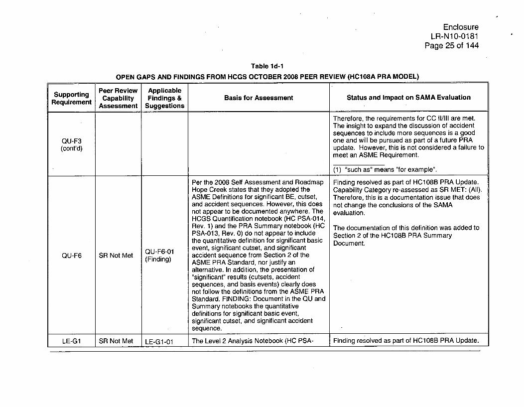
Per the 2008 Self Assessment and Roadmap Finding resolved as part of HC108B PRA Update.Hope Creek states that they adopted the Capability Category re-assessed as SR MET: (All).ASME Definitions for significant BE, cutset, Therefore, this is a documentation issue that doesand accident sequences. However, this does not change the conclusions of the SAMAnot appear to be documented anywhere. The evaluation.HCGS Quantification notebook (HC PSA-014,Rev. 1) and the PRA Summary notebook (HC The documentation of this definition was added toPSA-013, Rev. 0) do not appear to include Section 2 of the HC108B PRA Summarythe quantitative definition for significant basic Document.
QU-F6-01 event, significant cutset, and significantQU-F6 SR Not Met (Finding) accident sequence from Section 2 of the
ASME PRA Standard, nor justify an
alternative. In addition, the presentation of"significant" results (cutsets, accidentsequences, and basis events) clearly doesnot follow the definitions from the ASME PRAStandard. FINDING: Document in the QU andSummary notebooks the quantitativedefinitions for significant basic event,significant cutset, and significant accidentsequence.
LE-G1 SR Not Met LE-G1 -01 The Level 2 Analysis Notebook (HC PSA- Finding resolved as part of HC108B PRA Update.

EnclosureLR-N10-0181
Page 26 of 144
Table ild-1
OPEN GAPS AND FINDINGS FROM HCGS OCTOBER 2008 PEER REVIEW (HC108A PRA MODEL)
Supporting Peer Review Applicable
Requirement Capability Findings & Basis for Assessment Status and Impact on SAMA EvaluationAssessment Suggestions
(Finding) 015, Rev. 0) was very detailed, but was not Capability Category re-assessed as SR MET: (All).written in a manner conducive to This is a documentation issue that does not changedemonstrating the requirements of the the conclusions of the SAMA evaluation.standard were met. The documentation Additional specificity was added to the Roadmaproadmap (HC PSA-00, Rev. 0) for the Document following the Peer Review to furtherSupporting Requirements for LERF was not enhance the traceability between the ASME PRAhelpful in locating information within the Level Standard SRs and the documentation.2 notebook and in some cases incorrect.FINDING: Organize the Level 2 notebook in amanner conducive to demonstrating therequirements of the standard were met, andconsider including references to the PRAstandard in the Level 2 Analysis Notebook.For future reviews it would also be helpful(but not required for Capability Category II)provide specific references for the supportingrequirements in the PRA documentationroadmap.
The HCGS Quantification notebook (HC PSA- Finding resolved as part of HC108B PRA Update.014, Rev. 1) and the PRA Summary notebook Capability Category re-assessed as SR MET: (All).(HC PSA-01 3, Rev. 0) do not appear to Therefore, this is a documentation issue that does
QU-F6-01 document the quantitative definition for not change the conclusions of the SAMALE-G6 SR Not Met (Finding) significant accident. This finding is similar to evaluation.
that identified under QU-F6-01. The documentation of this definition was added to
Section 2 of the HC108B PRA SummaryDocument.

EnclosureLR-N1 0-0181
Page 27 of 144
1.e Confirm that any plant modifications or operating changes made since the freezedate for the Model 108B PRA do not have any effect on the conclusions of theSAMA assessment.
PSEG Response:
Hope Creek plant modifications and procedure changes since the freeze date ofthe HC108B model have been reviewed by Hope Creek Risk Managementpersonnel.
Hope Creek procedures require Risk Management personnel to review plantdesign changes and procedure changes on a quarterly basis, at a minimum. If adesign change or procedure change is judged to impact the PRA model ordocumentation, then a PRA Updates Requirement Evaluation (URE) isdeveloped by Risk Management personnel.
The plant modifications and procedure changes were reviewed and assessed asto their potential to impact the PRA. No changes were identified that requiredmodel updates.
Therefore, the plant modifications and procedure changes do not affect theconclusions of the SAMA assessment.
1 .f Briefly describe the overall quality assurance program applicable to the HCGS
Level 1 and 2 PRA and its updates.
PSEG Response:
Consistent with most industry PRA programs, the HCGS PRA program is notgoverned by the Quality Assurance guidelines per 10CFR50, Appendix B. TheHCGS Level 1 and 2 PRA quality assurance is dictated by the PSEG Trainingand Reference Material (T&RM) procedures. The HCGS PRA program isgoverned by a number of T&RMs to assure quality in the PRA process for thedevelopment, documentation, and maintenance of the PRA models. Somesignificant T&RMs include the following:
* T&RM ER-AA-600 "Risk Management'. This procedure specifies therequirements and responsibilities of the Risk Management (RM) Program atPSEG Nuclear facilities. This procedure defines technical activities necessaryto comply with governing regulatory requirements as they apply to the PSEGRM Program. This procedure identifies interfaces between the RM Programand other PSEG programs and functions.
* T&RM ER-AA-600-1011 "Risk Management Program". This T&RM providesguidelines for administrative activities of the PSEG Risk Management (RM)Program including the program's mission, values, strategy, success indicators,business practices, staffing, tools, methods and applications, in-houseawareness, industry involvement, deliverables, and organization; the division

EnclosureLR-N1O-0181
Page 28 of 144
of roles and responsibilities among the non-site, and site RM personnel;training and qualification of RM personnel; interfaces with regulatory agencies;and interfaces with other PSEG functions and programs.
* T&RM ER-AA-600-1012 "Risk Management Documentation". This T&RMprovides guidance for the documentation of RM products, tools, and basesdocuments. The PSEG quality process includes quality requirements for sign-offs of each product by 1) the preparer, 2) the reviewer, and 3) the approver,as required. Depending on the category of the RM documentation (e.g.,supports a License Amendment Request), an independent review may berequired for quality assurance.
" T&RM ER-AA-600-1014 "Risk Management Configuration Control". ThisT&RM provides an acceptable approach for controlling electronic storage ofRM products including PRA update information, PRA models and PRAapplications.
" T&RM ER-AA-600-1015 "FPIE PRA Model Update". This T&RM establishesresponsibilities and general guidelines for updating the full power, internalevents (FPIE) Probabilistic Risk Analysis (PRA) Models. This T&RM providesthe guidelines for the following:
o Maintenance of the PRA model and documentation
o Performing periodic and unscheduled PRA updates
o Roles and responsibilities during a PRA model update
o Reviewing the updated PRA model results
o Implementing the new model for PRA applications after a PRA modelupdate (e.g., high level guidelines to support online maintenanceactivities).

EnclosureLR-N10-0181
Page 29 of 144
2. Provide the following information relative to the Level 2 analysis:
2.a Provide a brief history of the development of the current HCGS Level 2 PRA,including for example, its relationship to the IPE level 2 model and the modelstatus relative to the various peer reviews.
PSEG Response:
The HCGS Level 2 IPE analysis was a full Level 2 model with a spectrum ofradionuclide release end states (including the Large, Early Release end state).The Level 2 IPE containment analysis model and documentation were sufficientlydetailed to address the issues required to meet the intent of the IPE. The Level 2IPE was developed and quantified using the EVNTRE software code.
For the HC108A PRA update, the Level 2 PRA model and documentation werecompletely upgraded to use the CAFTA suite of codes and allow dependenciesto be transferred from Level 1 to Level 2 using the Boolean Logic models. Someof the Level 2 PRA model attributes include the following:
* The Level 2 Containment Event Tree (CET) sequences and system fault treeswere completely revised to be consistent with the state of the technology andto address the requirements of the ASME PRA Standard.
* The Level 2 thermal hydraulic analysis was completely updated using plantspecific MAAP runs to support the accident progression and radionucliderelease characterization.
0 The HC108A Level 2 PRA was a full Level 2 model with a spectrum ofradionuclide release end states (e.g., High, Moderate, Low, or Low-Lowrelease magnitudes and Early, Intermediate, or Late release timings). Incomparison to the IPE, the HC108A Level 2 model included similarradionuclide release magnitude categories. However, the HC108A Level 2model included Early, Intermediate, and Late release timings, while the IPEonly included Early and Late release timings.
* The Level 2 PRA incorporated the latest EOPs, SAGs, and EALs in support ofthe Level 2 accident analysis and radionuclide release characterization.
* The Level 2 PRA accounts for the severe accident phenomenological impactson the plant mitigation capability.
• The Level 1 and Level 2 PRA models were converted to the CAFTA softwareenvironment as part of the earlier Model 2003A PRA update.
The HC108A Level 2 PRA model was reviewed as part of the Hope Creek 2008PRA Peer Review, conducted in accordance with NEI 05-04. The PRA PeerReview identified two (2) supporting requirements (SRs) that were "Not Met" forthe HC108A Level 2 PRA. SRs LE-G1 and LE-G6 were documentation issuesthat were both resolved as part of the subsequent HC108B PRA update used as

EnclosureLR-N10-0181
Page 30 of 144
input for the Hope Creek SAMA analysis. Refer to the response to RAI 1d foradditional details regarding the resolution of SR LE-G1 and LE-G6.
The HC108A PRA was updated after completion of the PRA peer review. Thechanges incorporated as part of the HC108B Level 2 PRA model included thefollowing:
0 Updated Level 2 containment isolation fault tree to reduce probability of basicevent CIS-LKG-PREXIST (PRE-EXISTING CONT. ISOL. FAILURES) from 5E-3 to 2.7E-3 to be more realistic based on BWR operating experience.
* Updated Level 2 containment isolation fault tree to include logic for failure ofthe Main Steam Lines or Main Steam Line Drains to isolate.
* Updated Level 2 containment isolation fault tree to include dependence ofReactor Building to torus vacuum breakers to fail open on loss of instrumentair.
Decreasing the probability of basic event CIS-LKG-PREXIST decreased theLarge Early Release Frequency (LERF) by approximately 1% for the HC108BPRA model. No other Level 2 model changes had a significant impact on theHC108B LERF.
2.b Section E.3.5 states that "representative [Modular Accident Analysis Program(MAAP)] cases for each of the release categories were chosen based on areview of the Level 2 model cutsets and the dominant types of scenarios thatcontribute to the results." Describe in more detail the process and criteria usedto assign the containment event tree end states to release categories and toselect the MAAP case to represent each release category.
PSEG Response:
It is noted that the references to tables included in this response use the tablenumbers as included in the SAMA submittal. The process for characterization ofrelease categories used in the MACCS2 offsite consequence calculations can besummarized as follows:

EnclosureLR-N10-0181
Page 31 of 144
1. Each of the CET end states is characterized with a radionuclide releasemagnitude and accident sequence timing. These end states arecharacterized using the following criteria:
Table E.2-3RELEASE SEVERITY AND TIMING CLASSIFICATION SCHEME"1 '
RELEASE SEVERITY RELEASE TIMING
CLASSIFICATION CESIUM IODIDE CLASSIFICATION TIME OF INITIAL RELEASE(2)
CATEGORY % IN CATEGORY RELATIVE TO TIME FORRELEASE GENERAL EMERGENCY
I_ DECLARATION
High (H) Greater than 10 Late (L) Greater than 24 hours
Medium or Moderate (M) 1 to 10 Intermediate (I) 4 to 24 hours
Low (L) 0.1 to 1 Early (E) Less than 4 hours
Low-low (LL) Less than 0.1
No iodine (OK) 0
(1) The combinations of severity and timing classification results in one OK release category and 12 other
release categories of varying times and magnitudes.(2) The cue for the General Emergency declaration is taken to be the time when EALs are exceeded. The
declaration of the General Emergency initiates the evacuation process.
These radionuclide release end states are summarized in Table E.2-4. Theyare shown to vary in frequency over a large range, from negligiblefrequencies to frequencies in the 1 E-6/yr range.

EnclosureLR-N10-0181
Page 32 of 144
Table E.2-4SUMMARY OF CONTAINMENT EVALUATION
INPUT OUTPUT
LEVEL 1 PRA CET EVALUATION
RELEASECORE DAMAGE CHARACTERIZE RELEASE BIN"1 ) FREQUENCYFREQUENCY RELEASE (PER YEAR)(4)
Little or No Release OK 2.12E-06
LL and Late 3.90E-08
LL and I 2.87E-07
Low Public LL and E 9.30E-08
Risk Impact L and Late(2) 2.88E-07
L and I 7.71 E-09
Land E 5.95E-10
Moderate Public Risk M and Late") O.OOE+00Impact
M and I 3.17E-07
M and E 3.57E-07
High Release H and Late(2) 1.26E-07
H and I 1.15E-06
H and E 4.72E-07131
(1) See Table E.2-3 for nomenclature on the release bins.k4) One of the areas in which PRA tools are somewhat limited is the estimation of recovery or repair
during extended times such as 24 hours. Some estimates would indicate that response over suchan extended time could be very extensive and highly successful. Therefore, it can be argued thatvirtually no accidents that take beyond 24 hours to release should be considered to be a significantpotential contributor to public risk.
(3) The accident class LERF total of 4.72E-7/yr is slightly lower than the base Level 2 LERF total of4.76E-7/yr from the single top model. This may be due to the assumption that all Class IV endstates were decreased proportionally due to the success branch probability issue. The Level 2LERF total of 4.76E-7/yr from the single top model is judged to be the appropriate LERF result.
(4) Release frequencies were calculated at a truncation limit of 1 E-1 2/yr.
2. Each CET sequence has an end state. The CET end state assignments aremade based upon a MAAP calculation for the accident sequence (or asimilar MAAP calculated sequence). Therefore, every CET end state isassigned a radionuclide release category based on the MAAP sequencecalculation and the criteria in Table E.2-3. From these Level 2 end states,

EnclosureLR-N1 0-0181
Page 33 of 144
additional decisions are made regarding how to incorporate these into theMACCS2 consequence calculation.
3. Given the 13 end states noted in Table E.2-4, there is some additionalrefinement and source consolidation of the end states recognizing that: (1)the consequence calculations from MACCS2 are somewhat insensitive tominor shifts in the lower consequence categories; (2) some releasecategories (e.g., M/L, L/, LIE) have very low frequencies and consequencesthat are also lower than the more dominant release categories; and, (3) thehigh consequence categories may be subdivided to refine their riskcalculation in MACCS2.
For example, it is noted that the High/Early release category is expected tobe a significant contributor to offsite dose and economic effects. Therefore,it was divided into three separate MACCS2 Source Terms so that thesefrequencies could be appropriately represented.
In addition, a simple comparison among the eleven Source Term groupschosen for MACCS2 analysis (see Table E.3-7) show'that those for ST1through ST8 have offsite consequence costs that are all within a factor ofapproximately 2.5. This is judged not to be a large spread to be representedby eight (8) groups. The remaining three (3) groups have very low offsiteeconomic consequences compared with ST1 through ST8. These also havean OECR that are negligible compared with ST1 through ST8.
4. The criteria for the selection of MAAP cases to be used in thecharacterization of offsite consequences are as follows:
o Establish the dominant contributors to each radionuclide release category
o Find a MAAP case that models the accident progression events, timing,and radionuclide release magnitude for the dominant contributors
o Use the representative MAAP case for these dominant contributors.
5. The sequences were rank ordered by release category and then the highestfrequency sequences and their cutsets were examined to find arepresentative MAAP sequence that models the core melt progressionpathway and timing.
6. The accident sequences for each radionuclide release category are thenreviewed to identify the types of sequences that comprise the bin. Based onthe sequences and cutsets that appear in the release bin, a MAAP calculationfor the most representative set of cutsets and sequences was selected. Thisis generally the highest consequence MAAP sequence.

EnclosureLR-N10-0181
Page 34 of 144
7. The results of this assessment are shown in Table E.3-5 which includes theSource Term designation for the MACCS2 input, the associated Level 2release category, and the selected MAAP case used to characterize therelease.
Table E.3-5REPRESENTATIVE MAAP LEVEL 2 CASE DESCRIPTIONS AND
KEY EVENT TIMINGS
SOURCE RELEASE MAAP CASE REPRESENTATIVE Csl Tcd TVF Tcf TendTERM CATEGORY CASE DEFINITION RF(1) (HRS)(2) (HRS)(3) (HRS)(4 ) (HRS)(5 )
ST1 H/E-HP HC070500 Loss of makeup at high 0.57 0.60 3.0 3.2 38pressure. No
IA-L2-NSPR containment sprays.
ST2 H/E-LP HC070504 Loss of makeup at low 0.15 0.47 4.7 4.8 38pressure. No
ID-L2-NSPR containment sprays.
ST3 H/E-BOC HC070524 Main steam line break 0.69 0.13 6.8 6.9 38outside containment.
V-L2-17 No injection. Releaseto environment begins
at core damage.
ST4 H/I HC070509 Loss of containment 0.30 29.1 38.6 29.8 72heat removal and
IIT-L2-WWW subsequent wetwellfailure. RCIC and corespray provide injection.
SRVs reclose at 50psid. No containment
sprays.
ST5 H/L HC070515 Loss of containment 0.36 35.4 46.4 34.4 84heat removal and
IIA-L2-WWW subsequent wetwellfailure. CRD, RCIC and
core spray provideinjection. SRVs reclose
at 50 psid. Nocontainment sprays.
ST6 M/E HC070519 ATWS event with SLC 0.070 0.77 5.4 0.58 38failure and emergency
IVA-L2-ED- depressurization. FW,WWA HPCI, and LPCI provide
injection untilcontainment failure.

EnclosureLR-N1 0-0181
Page 35 of 144
Table E.3-5REPRESENTATIVE MAAP LEVEL 2 CASE DESCRIPTIONS AND
KEY EVENT TIMINGS
SOURCE RELEASE MAAP CASE REPRESENTATIVE CsI Tcd TVF Tcf TendTERM CATEGORY CASE DEFINITION RF(1) (HRS)(2 ) (HRS)(3) (HRS)(4 ) (HRS)(5)
ST7 M/I HC070516 Loss of containment 0.057 35.4 46.5 34.4 84heat removal and
IIA-L2-DW subsequent drywellfailure. CRD, RCIC, and
core spray provideinjection. SRVs reclose
at 50 psid. Nocontainment sprays.
ST8 M/L HC070502 Loss of makeup at high 0.040 0.58 3.0 21.8 38pressure.
IA-L2-SPRY-AContainment sprays failat containment failure.
ST9 L/ E, LL / E, HC070503 Loss of makeup at high 2.3E-6 0.58 3.0 21.8 38L / I, LLII pressure. Containment
IA-L2-SPRY-B sprays operate pastcontainment failure.
ST1 0 L / L, LL / L HC070505 Loss of makeup at low 9.8E-5 0.47 4.8 32.2 38pressure. Containment
ID-L2-SPRY sprays fail atcontainment failure.
ST1 1 Intact HC070525A Loss of makeup at high 1.7E-6 0.58 3.1 NA 38pressure. Containment
OK-L2-A sprays and suppressionpool cooling operate.
Intact containment withtechnical specification
leakage.
(1)
(2)
(3)
(4)
(5)
Csl RF - Cesium Iodide release fraction to the environment
Tcd - Time of core damage (maximum core temperature >18000 F)
TVF - Time of vessel breach
Tcf - Time of containment failure
Tend - Time at end of run

EnclosureLR-N1 0-0181
Page 36 of 144
Table E.3-7
MACCS2 BASE CASE MEAN RESULTS
SOURCE RELEASE DOSE OFFSITE FREQ. DOSE RISK OECRTERM CATEGORY (P-REM) ECONOMIC (/YR)(1) (P-REM/YR) ($IYR)
COST ($)
ST1 H/E-HP 1.82E+07 1.15E+11 1.830E-07 3.33E+00 2.1OE+04
ST2 H / E - LP 1.38E+07 9.63E+10 7.152E-08 9.87E-01 6.89E+03
ST3 H / E - BOC 2.34E+07 1.15E+11 1.302E-07 3.05E+00 1.50E+04
ST4 H /I 8.75E+06 6.41 E+10 9.697E-07 8.49E+00 6.22E+04
ST5 H / L 1.10E+07 9.23E+10 8.336E-08 9.17E-01 7.69E+03
ST6 M / E 1.31 E+07 9.17E+10 3.477E-07 4.55E+00 3.19E+04
ST7 M/ I 6.34E+06 4.73E+10 2.164E-07 1.37E+00 1.02E+04
ST8 M/ L 6.38E+06 5.35E+10 0.OOOE+00 0.OOE+00 O.OOE+00
ST9 L/E, LI, LL/E, 6.44E+03 2.54E+05 2.677E-07 1.72E-03 6.80E-02LIJI
ST10 LUL, LLIL 6.87E+05 7.41 E+08 2.392E-07 1.64E-01 1.77E+02
ST1 1 INTACT 1.01 E+03 3.63E+04 1.933E-06 1.95E-03 7.02E-02
FREQUENCY WEIGHTED 4.44E-06 2.29E+01 1.55E+05TOTALS
(1) Release frequencies were calculated at a truncation limit of 5E-1 1/yr.

EnclosureLR-N1 0-0181
Page 37 of 144
2.c Table E.3-5 indicates that for ST5 (loss of containment heat removal withsubsequent wetwell failure) the cesium iodine release fraction is 0.36 while forST7 (loss of containment heat removal with subsequent drywell failure) therelease fraction is only 0.057. This appears counterintuitive. In addition, the starttime of Plume 1 in Table E.3-6 for ST5 (H/L) and ST7 (M/1) appear to be roundeddifferently (i.e., 36 h versus 35 h, respectively but should be the same per TableE.3-5). Describe the assumptions and/or phenomena that lead to these results.
PSEG Response:
The representative sequence for ST5 involves an overpressure failure ofcontainment occurring in the wetwell region below the normal water level. Theelevation of the break results in a reduction in fission product scrubbing (via theSRV discharge) after the overpressure failure occurs at 34.4 hrs. For the ST7category, the initial overpressure failure of the drywell does not impact thesuccessful scrubbing of fission products via the SRV discharge path. In bothcases, the drywell shell is assumed to fail after vessel breach and provides adirect path for radionuclide transport into the reactor building. A detailed reviewof the results shows that about 30% of the total Csl inventory is trapped in thesuppression pool for ST5 compared to 60% for the ST7 case. Any airbornefission products remaining after drywell shell failure can contribute to the totalrelease.
Differences in the fission product release pathway and scrubbing effectivenessserve to explain the impact on the total release. The sequence of events startswith overpressure of the containment, followed by loss of injection, and eventualcore heatup and radionuclide release. The crucial difference between ST5 andST7 is that suppression pool scrubbing is completely unavailable in ST5 prior toany radionuclide release from the RPV. While ST7 has the benefit of poolscrubbing for the entire duration of the in-vessel core melt progression.
The timing of the initial plume release occurs prior to vessel breach and isimpacted by the fission product release pathways described above. Thesepathways are different and can result in slightly different times for the onset of therelease.

EnclosureLR-N1 0-0181
Page 38 of 144
3. Provide the following information with regard to the treatment and inclusion of externalevents in the SAMA analysis:
3.a For both the internal fire and seismic assessments, it is indicated that the 2003update used the conditional core damage probabilities (CCDPs) based on the2003 internal event PRA revision. However, on page E-87 it is stated that "theunderlying system and plant response models that these analyses rely uponhave not been updated since the completion of the [individual plant examinationof external events (IPEEE)] in 1997." Clarify the meaning of the latter statement.It would appear that using CCDPs from the 2003 PRA is using updated systemmodels.
PSEG Response:
The CCDPs were based on the 2003A PRA model (August 2003). For the set offailures identified for a given fire or seismic scenario, the 2003A PRA model wasquantified to calculate the resulting CCDP that was used to obtain the CDFs forthe fire and seismic models.
The statement on page E-87 is also correct and was intended to communicatethat the failures caused by a fire or seismic event are still based on the analysisthat was performed as part of the IPEEE. For the set of fire and seismic eventsthat were analyzed, the IPEEE contains information about the consequences tothe plant systems for those events (e.g., what equipment is failed by a fire in DGRoom "C" for a specific fire scenario). This information was retained and used todefine the boundary conditions used in the CCDP quantifications.
3.b Describe the meaning of the column headings in Table E.5.4. Clarify whether thevalues in the column titled "HCGS Seismic IPEEE HEP" are those used in theoriginal seismic IPEEE or the 2003 update. If from the IPEEE, then themodifications described in the final column appear to represent no change fromthe IPEEE, rather then eliminating "the non-conservative nature of the originalseismic analysis" as stated on page E-98.
PSEG Response:
The second bullet on page E-98 is incorrect. As written, it indicates that theoriginal seismic analysis was non-conservative because it had not accounted forthe impact of seismic events on the HEPs. However, seismic specific HEPswere developed and incorporated into the IPEEE. This bullet should haveindicated that the HEPs in the 2003A PRA model were modified to reflect theseismic HRA that was performed to support the IPEEE.
The modified version of the 2003A PRA model was then used to develop theconditional core damage probabilities (CCDPs). These CCDPs were used inconjunction with the EPRI seismic hazard curves to calculate the seismic coredamage frequencies that were used in the HCGS SAMA analysis.
EnclosureLR-N10-0181
Page 39 of 144
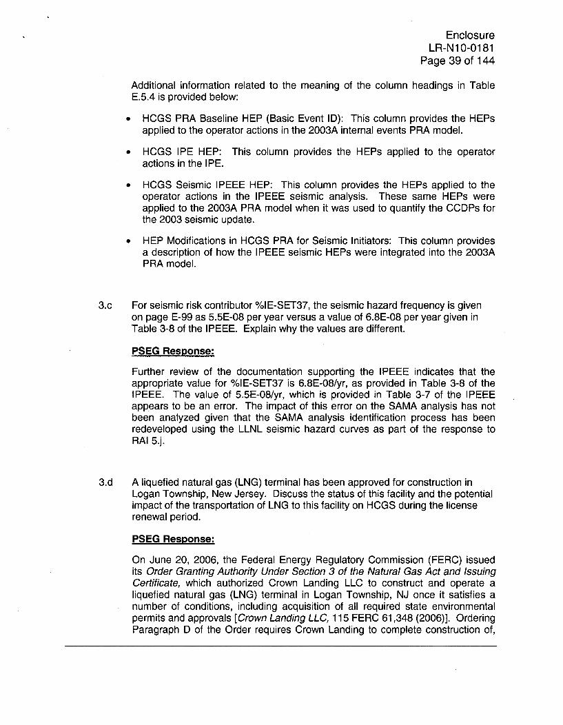
Additional information related to the meaning of the column headings in TableE.5.4 is provided below:
* HCGS PRA Baseline HEP (Basic Event ID): This column provides the HEPsapplied to the operator actions in the 2003A internal events PRA model.
• HCGS IPE HEP: This column provides the HEPs applied to the operatoractions in the IPE.
* HCGS Seismic IPEEE HEP: This column provides the HEPs applied to theoperator actions in the IPEEE seismic analysis. These same HEPs wereapplied to the 2003A PRA model when it was used to quantify the CCDPs forthe 2003 seismic update.
* HEP Modifications in HCGS PRA for Seismic Initiators: This column providesa description of how the IPEEE seismic HEPs were integrated into the 2003APRA model.
3.c For seismic risk contributor %IE-SET37, the seismic hazard frequency is givenon page E-99 as 5.5E-08 per year versus a value of 6.8E-08 per year given inTable 3-8 of the IPEEE. Explain why the values are different.
PSEG Response:
Further review of the documentation supporting the IPEEE indicates that theappropriate value for %IE-SET37 is 6.8E-08/yr, as provided in Table 3-8 of theIPEEE. The value of 5.5E-08/yr, which is provided in Table 3-7 of the IPEEEappears to be an error. The impact of this error on the SAMA analysis has notbeen analyzed given that the SAMA analysis identification process has beenredeveloped using the LLNL seismic hazard curves as part of the response toRAI 5.j.
3.d A liquefied natural gas (LNG) terminal has been approved for construction inLogan Township, New Jersey. Discuss the status of this facility and the potentialimpact of the transportation of LNG to this facility on HCGS during the licenserenewal period.
PSEG Response:
On June 20, 2006, the Federal Energy Regulatory Commission (FERC) issuedits Order Granting Authority Under Section 3 of the Natural Gas Act and IssuingCertificate, which authorized Crown Landing LLC to construct and operate aliquefied natural gas (LNG) terminal in Logan Township, NJ once it satisfies anumber of conditions, including acquisition of all required state environmentalpermits and approvals [Crown Landing LLC, 115 FERC 61,348 (2006)]. OrderingParagraph D of the Order requires Crown Landing to complete construction of,

EnclosureLR-N10-0181
Page 40 of 144
and make available for service, the authorized facilities within three years of thedate of the Order - by June 20, 2009. In a letter dated April 17, 2009, the FERCextended the deadline for completing construction and puffing the LNG terminalinto service until June 20, 2010. In a letter dated March 15, 2010, BP, the ownerof Crown Landing LLC, notified the FERC that 100 percent ownership of CrownLanding LLC was transferred to Hess LNG Crown Landing LLC, a Hess LNGaffiliate, effective October 28, 2009.
PSEG Nuclear has determined that construction of the Crown Landing LNGterminal had not yet commenced as of March 31, 2010. Furthermore, theDelaware Department of Natural Resources and Environmental Control hasdenied applications for several required environmental permits and approvals.Hence, although the Crown Landing LNG terminal may ultimately be constructedand placed into service, details concerning LNG deliveries to the terminal areuncertain at this time. Accordingly, any assessment of specific severe accidentimpacts on Hope Creek during the license renewal period from transportation ofLNG to the Crown Landing LNG terminal would be purely speculative. Even so,considering the regulatory process and controls for assuring safety and securitythat apply to LNG marine traffic and tankers and the safety record of LNG ships,all of which are summarized in the following paragraphs, PSEG believes analysisfor Hope Creek of severe accident mitigation alternatives associated with apossible future LNG terminal in Logan Township, NJ, is not currently warranted.
Regulation of LNG Marine Traffic
While the FERC is the federal agency responsible for authorizing constructionand operation of onshore LNG facilities, the U.S. Coast Guard (Coast Guard) isthe federal agency responsible for issuing Letters of Recommendation (LORs)pursuant to 33 CFR 127.009 regarding the suitability for LNG marine traffic of thewaterways on which such facilities will be located. The Coast Guard is alsoresponsible for matters related to navigation safety, vessel engineering andsafety standards, and all matters pertaining to the safety of facilities or equipmentlocated in or adjacent to navigable waters up to the last valve immediately beforethe receiving tanks.
The Coast Guard bases its LOR for a waterway on the following:
* Information in a letter of intent submitted by the owner or operator of theproposed LNG facility, which must provide:
o The physical location of the facility
o A description of the facility
o The LNG vessels' characteristics and the frequency of LNG shipments toor from the facility
o Charts showing waterway channels and identifying commercial, industrial,environmentally sensitive, and residential areas in and adjacent to thewaterway used by the LNG vessels en route to the facility, within 25kilometers (15.5 miles) of the facility.

EnclosureLR-N1 0-0181
Page 41 of 144
* Density and character of marine traffic in the waterway
* Locks, bridges, or other manmade obstructions in the waterway
* The nature of the following factors adjacent to the facility:
o Depths of the watero Tidal rangeo Protection from high seaso Natural hazards, including reefs, rocks, and sandbarso Underwater pipelines and cableso Distance of berthed vessel from the channel and the width of the channel
The process of preparing the LOR begins when an applicant submits a Letter ofIntent (LOI) to the appropriate Captain of the Port (COTP) in accordance with33 CFR 127.007. If the Coast Guard were to issue a LOR that found theDelaware Bay/River waterway suitable for LNG marine traffic, the arrival, transit,cargo transfer, and departure of LNG ships in the Delaware River would berequired to adhere to the procedures of a LNG Vessel Transit Management Plan,which would be developed by the Coast Guard Sector Delaware Bay. Inaddition, the LNG terminal itself would develop Operations and EmergencyManuals in consultation with the Coast Guard. These procedures would bedeveloped to ensure the safety and security of all operations associated withLNG ship transit and unloading. The LNG Vessel Transit Management Planwould contain specific requirements for LNG ships, pre-arrival notification, transitthrough the Delaware Bay and River, the waterfront facility, cargo transferoperations, Coast Guard inspection and monitoring activities, and emergencyoperations. The Coast Guard Sector Delaware Bay would monitor each LNG shipin accordance with the LNG Vessel Transit Management Plan. Some of theanticipated key provisions of an LNG Vessel Transit Management Plan areestablishment of a moving safety and/or security zone for all inbound andmoored LNG ships, use of tugs to assist in the Delaware River and to maneuverthe ship into the berth, and requirement that tug(s) remain with the LNG shipwhile it is moored at the berth.
If the Coast Guard issues a LOR finding the waterway suitable for LNG marinetraffic the Coast Guard would promulgate a moving safety zone which wouldaffect other vessels. Pursuant to such a regulation, no vessel would be allowedto enter the safety zone without first obtaining permission from the Coast GuardCOTP. The COTP currently places similar restrictions on all vessels transitingthe Delaware River and Bay carrying certain dangerous cargoes (CDC) byregulation in 33 CFR 165.510. Presently, the moving safety zone around LNGships is 1,000 yards ahead and behind, and 500 yards on either side of thevessel. Minimum visibility conditions would have to be satisfied before the LNGship would be allowed to proceed inbound from the ocean, ensuring that theCoast Guard could adequately monitor the safety zone. Currently there is a 100

EnclosureLR-N10-0181
Page 42 of 144
yard security zone for moored or anchored vessels carrying dangerous cargo.The regulation provides the Coast Guard and local law enforcement personnelwith the authority to implement additional control measures within the zone, suchas check points, should such action be warranted based on a specific threat orcredible intelligence. Additionally, it is important to note that the requirements of33 CFR 165.150 were designed to apply to any CDC vessel transiting theDelaware Bay and River, and does give consideration to security measures thatmay be applied to mitigate risk.
Regulation of Ship Design and Construction
Besides complying with the Coast Guard's controls on LNG marine traffic, LNGships used to import LNG to the United States would be constructed andoperated in accordance with the International Maritime Organization (IMO) Codefor the Construction and Equipments of Ships Carrying Liquefied Gases in Bulk,the International Convention for the Safety of Life at Sea (SOLAS), and 46 CFRPart 154, which contain the U.S. safety standards for vessels carrying bulkliquefied natural gas. Foreign flag LNG ships are required to possess a validIMO Certificate of Fitness and a Coast Guard Certificate of Compliance. In 1993,amendments to the IMO's Code for the Construction and Equipments of ShipsCarrying Dangerous Chemicals in Bulk required all tankers to have monitoringequipment with an alarm facility which is activated by detection of over-pressureor under-pressure conditions within a cargo tank. In addition, the cargo tanks areheavily instrumented, with gas detection equipment in the hold and inter-barrierspaces, temperature sensors, and pressure gauges. Fire protection must includethe following systems:
* A water spray (deluge) system that covers the accommodation house controlroom and all main cargo valves;
* A traditional firewater system that provides water to fire monitors on deck andto fire stations found throughout the ship;
" A dry chemical fire extinguishing system for hydrocarbon fires; and
* A carbon dioxide system for protecting machinery, including the ballast pumproom, emergency generators, and compressors.
As a result of the terrorist acts that occurred on September 11, 2001, the IMOagreed to new amendments to the 1974 SOLAS addressing port facility and shipsecurity. As a result, the International Ship and Port Facility Security Code wasadopted in 2003 by the IMO. This code requires both ships and ports to conductvulnerability assessments and to develop security plans. The purpose of thecode is to prevent and suppress terrorism against ships, improve security aboardships and ashore, and reduce the risk to passengers, crew, and port personnelon board ships and in port areas, for vessels and cargoes. All LNG ships, as wellas other cargo vessels 300 gross tons and larger and ports servicing thoseregulated vessels, must adhere to these IMO and SOLAS standards. Some ofthe IMO requirements are as follows:

EnclosureLR-N10-0181
Page 43 of 144
* Ships must develop security plans and have a Ship Security Officer
Ships must be provided with a ship security alert system. These alarmstransmit ship-to-shore security alerts to a competent authority designated bythe Administration, which may include the company, identifying the ship, itslocation and indicating that the security of the ship is under threat or it hasbeen compromised
* Ships must have a comprehensive security plan for international port facilities,focusing on areas having direct contact with ships
* Ships may have certain equipment onboard to help maintain or enhance the
physical security of the ship.
LNG Ship Safety
Since 1959, LNG has been transported by ship without a major release of cargoor a major accident involving an LNG ship. Starting in 1971, LNG began arrivingat the Distrigas facility in Everett, Massachusetts. As of early 2006, more than680 cargoes, with volumes ranging from 60,000 to 125,000 M3, have beendelivered into the Port of Boston without incident. During 2005, an estimatedtotal of 631 billion cubic feet (241 cargoes) of LNG was imported into the UnitedStates. For 35 years, LNG shipping operations have been safely conducted inthe United States. [Federal Energy Regulatory Commission, 2006. FinalEnvironmental Impact Statement, Crown Landing LNG and Logan LateralProjects. Docket Nos. CP04-411-000 and CP04-416-000. FERC/ElS - 0179.April.]
The world's LNG ship fleet currently exceeds 173 carriers. Over the last 45years, LNG ships have made over 44,000 voyages. Currently, all of the ships inthe LNG fleet operate under a foreign flag with foreign crews. A foreign flag shipmust have a Certificate of Compliance inspection by the Coast Guard to ensurecompliance with international safety standards. [Federal Energy RegulatoryCommission, 2006. Final Environmental Impact Statement, Crown Landing LNGand Logan Lateral Projects. Docket Nos. CP04-411-000 and CP04-416-000.FERC/EIS - 0179. April.]
Conclusion
Based on (1) the regulatory process and controls for assuring the safety andsecurity of LNG ships, (2) the safety record of LNG ships, and (3) the uncertaintyof the Crown Landing LNG terminal project, PSEG submits that analysis for HopeCreek of severe accident mitigation alternatives associated with a possible futureLNG terminal in Logan Township, NJ, is not currently warranted.

EnclosureLR-N10-0181
Page 44 of 144
4. Provide the following information concerning the MACCS2 analysis:
4.a Section E.3.2 states that SECPOP2000 census data from 1990 to 2000 wereused to determine the population growth factor, and that the population growthwas averaged over each ring and applied uniformly to all sectors within eachring. Using an average growth over a ring mixes growth rates from significantlydifferent regions. For example; portions of Kent County, Delaware; ChesterCounty, Pennsylvania; and Cumberland County, New Jersey will lie on similarrings. Between years 2000 and 2003, they had population growths of 6.1percent, 5.5 percent and 2.0 percent, respectively(http://www.epodunk.com/topl 0/countyPop/coPop8.html,http://www.epodunk.com/topl0/countyPop/coPop39.html, andhttp://www.epodunk.com/topl0/countyPop/coPop3l.html). Provide anassessment of the potential impact on population dose risk (PDR) and offsiteeconomic cost risk (OECR) if a wind-direction-weighted growth estimate for eachsector were used.
PSEG Response:
Population projection necessitates a range of approximations. In general,population growth rates are found to differ substantially based on radial distancefrom the site and it is desirous to include these radial variations. Angularvariations in growth rates are generally viewed as being of secondary importancedue to lateral plume dispersion as a function of distance and the use of meanvalues in the SAMA analysis; however, it can be envisioned that angularpopulation growth rate variations could become important if combined with strongwind direction variations.
Significant radial growth rate differences for the 1990 to 2000 period are evidentin the Hope Creek radial growth rates for each ring around the site, varying from38% per ten years for the 4-to-5 mile ring to 1% per ten years at the 30-to-40mile ring. 'Whole County" based population growth rates do not addresspopulation growth rate differences within a county and often do not capture theradial variation in relationship to the site (dependent upon the size andorientation of the county relative to the site). For example, Cumberland County,NJ situated due east of the site begins approximately 7 miles from the site andextends to approximately 35 miles from the site. Growth rate variations used inthe SAMA analysis varied between 17% (5-to-10 mile ring) and 1% (30-to-40mile ring) for this county. Use of a single county growth rate value forCumberland County would not capture this radial variation. Similarly, for KentCounty, DE, located approximately due south of the site (extending from anapproximate radial distance of 8 miles to 45 miles) the SAMA analysis growthrates varied from 1% to 17%. For Chester County, PA, (which extendsapproximately 23 miles from the site to outside the 50-mile region), the SAMAanalysis growth rates varied from 1% to 9% dependent upon the distance fromthe site.
As part of the MACCS2 processing of meteorological data, wind direction istabulated and binned for the 8760 hours of annual data according to 16

EnclosureLR-N1O1-01 81
Page 45 of 144
directional sectors. For the Hope Creek SAMA base case year of meteorology(2004), the wind direction frequency is found to be relatively even for the 16sectors, as shown in the following table:
WindWind Bin Direction Frequency Downwind Counties(Sector) (Blowing (Iyr)
Towards)________________________1 N 0.056 NJ - Salem, Gloucester
PA - Delaware, Chester, Philadelphia, MontgomeryDE - New Castle
2 NNE 0.059 NJ - Salem, Gloucester, Camden, BurlingtonPA - Philadelphia, Montgomery
3 NE 0.062 NJ - Salem, Cumberland, Gloucester, Camden, Atlantic,Burlington
4 ENE 0.057 NJ - Salem, Cumberland, Gloucester, Atlantic, Burlington5 E 0.058 NJ - Salem, Cumberland, Atlantic, Cape May6 ESE 0.067 NJ - Salem, Cumberland, Cape May7 SE 0.101 Primarily Delaware Bay
NJ - Salem, Cape May_________DE - Kent, Sussex
8 SSE 0.069 NJ - SalemDE - New Castle, Kent, Sussex
9 5 0.066 NJ - SalemDE - New Castle, Kent, SussexMD - Caroline, Talbot
10 SSW 0.069 NJ - Salem.DE - New Castle, KentMD - Kent, Queen Anne's, Caroline, Talbot
11 SW 0.067 NJ - SalemDE - New Castle
_________MD - Kent, Cecil, Queen Anne's, Baltimore12 WSW 0.046 NJ - Salem
DE - New CastleMD - Kent, Cecil, Hartford, Baltimore
13 W 0.027 NJ -SalemDE - New CastleMD - Cecil, Hartford
___________________PA - York, Lancaster14 WNW 0.028 NJ -Salem
DE - New CastleMD - Cecil
________ ___________PA - Chester, Lancaster, York15 NW 0.099 NJ - Salem
DE - New CastlePA - Chester, Lancaster
16 NNW 0.067 NJ -SalemDE - New CastlePA - Chester, Delaware, Montgomery
Total -- 1.00 -
.Average -- 0.063 -
Per the table above, the highest wind frequency (0.101, Southeast) is primarilyassociated with the Delaware Bay. This sector has negligible population. Thesecond highest wind frequency (0.099) is in the opposite direction (i.e.,
EnclosureLR-N10-0181
Page 46 of 144
Northwest) and includes a significant portion of Chester County, PA. One of thelowest frequencies (i.e., 0.028, WNW) is adjacent and contains portions ofsouthern Chester County. The other adjacent sector (NNW) also containssignificant portions of Chester County and has a frequency (0.067) close to theaverage (0.063). It is noted that for Chester County which is situated more than20 miles from the site, a postulated release is expected to have dispersedlaterally across several sectors by the time such a radial distance is achieved. Ifthe frequencies of the three primary sectors for Chester County (i.e., WNW, NW,and NNW) are averaged, a frequency of 0.065 is determined((0.028+0.099+0.067)/3=0.0647), which is very close to the average sector valueof 0.063.
Based on the relatively even wind direction profile surrounding the site, thepropensity for lateral release dispersion into adjacent sectors as a function ofradial distance, and the use of mean values in the SAMA analysis, it is judgedthat the impacts associated angular growth rates are minimal and bounded bythe 30% population increase sensitivity case that was performed as part of theSAMA analysis.
4.b Section E.3.2 does not discuss transient population. Clarify whether transientpopulation was considered in the analysis. If a transient population was notconsidered, provide a justification/rationale for not including it.
PSEG Response:
Transient population was included for the 10-mile region around the site basedon data in the site evacuation time estimate study (Reference KLD 2004 inAppendix E of the Environmental Report). Transient population data wasincluded prior to population projection. This is consistent with the guidance inNEI 05-01. Transient data are most applicable to evacuation-related modeling.
4.c Section E.7.3.4 describes a population sensitivity case in which the 2040population was uniformly increased by 30 percent in all sectors of the 5-mileradius. Section E.3.2 states that SECPOP2000 census data from 1990 to 2000were used to determine the 10 year population growth factor. It is unclear if the30 percent sensitivity case bounds the population growth rate if updatedpopulation growth estimates are used (see request for additional information(RAI) 4a). Provide an assessment of the impact on PDR and OECR usingcurrently available population growth estimates for the surrounding counties andstates.
PSEG Response:
As indicated in the response to RAI 4.a, the use of "whole county" growthestimates is not generally preferred since the resolution of such data is less thanthat available using the data contained in the SECPOP2000 census data.
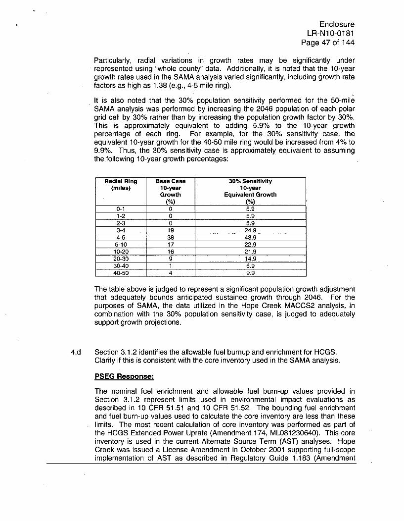
EnclosureLR-N10-0181
Page 47 of 144
Particularly, radial variations in growth rates may be significantly underrepresented using "whole county" data. Additionally, it is noted that the 10-yeargrowth rates used in the SAMA analysis varied significantly, including growth ratefactors as high as 1.38 (e.g., 4-5 mile ring).
It is also noted that the 30% population sensitivity performed for the 50-mileSAMA analysis was performed by increasing the 2046 population of each polargrid cell by 30% rather than by increasing the population growth factor by 30%.This is approximately equivalent to adding 5.9% to the 10-year growthpercentage of each ring. For example, for the 30% sensitivity case, theequivalent 10-year growth for the 40-50 mile ring would be increased from 4% to9.9%. Thus, the 30% sensitivity case is approximately equivalent to assumingthe following 10-year growth percentages:
Radial Ring Base Case 30% Sensitivity(miles) 10-year 10-year
Growth Equivalent Growth(%) (%)
0-1 0 5.91-2 0 5.92-3 0 5.93-4 19 24.94-5 38 43.9
5-10 17 22.910-20 16 21.920-30 9 14.930-40 1 6.940-50 4 9.9
The table above is judged to represent a significant population growth adjustmentthat adequately bounds anticipated sustained growth through 2046. For thepurposes of SAMA, the data utilized in the Hope Creek MACCS2 analysis, incombination with the 30% population sensitivity case, is judged to adequatelysupport growth projections.
4.d Section 3.1.2 identifies the allowable fuel burnup and enrichment for HCGS.
Clarify if this is consistent with the core inventory used in the SAMA analysis.
PSEG Response:
The nominal fuel enrichment and allowable fuel burn-up values provided inSection 3.1.2 represent limits used in environmental impact evaluations asdescribed in 10 CFR 51.51 and 10 CFR 51.52. The bounding fuel enrichmentand fuel burn-up values used to calculate the core inventory are less than theselimits. The most recent calculation of core inventory was performed as part ofthe HCGS Extended Power Uprate (Amendment 174, ML081230640). This coreinventory is used in the current Alternate Source Term (AST) analyses. HopeCreek was issued a License Amendment in October 2001 supporting full-scopeimplementation of AST as described in Regulatory Guide 1.183 (Amendment

EnclosureLR-N10-0181
Page 48 of 144
134, ML012600176). The SAMA MACCS2 analysis was based on the coreinventory used in the current AST analyses and thus is consistent with thecurrent design and licensing bases.

EnclosureLR-N10-0181
Page 49 of 144
5. Provide the following with regard to the SAMA identification and screening process:
5.a For most Table E.5-1 initiating events (e.g., %IE-SWS, %IE-TE, %IE-MS, %IE-TT, %IE-S2-WA) it is stated that "this initiator event is a compilation of industryand plant specific data (No specific SAMA identified.)." Provide assurance thatfor each of these initiating events there is not a dominant contributor for which apotential SAMA to reduce the initiating event frequency or mitigate the impact ofthe initiator would not be viable. For example, while the above statement ismade for initiator %IE-SWS, potential SAMAs were in fact identified for eventNR-IE-SWS, Non-recovery of the loss of SWS initiator.
PSEG Response:
Typically, the importance list review process includes not only the considerationof the event itself, but the series of events that lead up to, and follow, the event ofimportance. SAMAs are derived not only to bypass or improve the reliability ofthe components or actions represented by the event, but to also find ways toreduce challenges to the action/component or to mitigate the failure of theaction/component.
For any given initiating event on the importance list, the events important to theinitiator are generally also represented on the importance list. Given that this istrue, the approach taken in the HCGS importance list review was to treat theinitiators separately to clarify the nature of how the initiating event values werederived.
For documentation purposes, the contributors to each of the important initiatingevents have been identified and correlated to the importance list review that wasprovided in the ER:
* %IE-SWS (LOSS OF SERVICE WATER INITIATING EVENT): 100 percent ofthe cutsets including this initiating event include the event NR-IE-SWS, whichis addressed in the importance list review (refer to the response to RAI 5b foradditional information about the disposition of this initiating event). Therefore,the important sequences including %IE-SWS have been considered.
* %IE-TE (LOSS OF OFFSITE POWER INITIATING EVENT): Loss of offsitepower events are well represented in the importance list review. For example,the following events, which are important to the scenarios which involve the%IE-TE initiator, are all addressed by the importance list review: LOOP-IE-SW, NR-XTIE-EDG, OSPR20HR-SW, DCP-XHE-PORTA, RX-FWR-POR,DGS-DGN-FS-BG400, DGS-DGN-FS-DG400, HPI-TDP-FS-OP204, andOSPR7HR-SW. The SAMAs that were identified to mitigate these scenariosinclude:
o SAMA 1: Remove ADS inhibit from non-ATWS emergency operatingprocedures (reduces high pressure core melts in LOOP scenarios)
o SAMA 5: Restore AC power with onsite gas turbine (provides an alternateAC power source for LOOP events)

EnclosureLR-N10-0181
Page 50 of 144
o SAMA 10: Provide procedural guidance to use B.5.b low pressure pumpfor non-security events (mitigates long term SBO scenarios)
%IE-MS (MANUAL SHUTDOWN INITIATING EVENT): Manual shutdownscenarios are well represented in the importance list review. For example, thefollowing events, which are important to the scenarios which involve the %IE-MS initiator, are all addressed by the importance list review: RHS-REPAIR-TR, ADS-XHE-OK-INHIB, NR-UlX-DEP-SRV, ACP-BAC-HV-RMCLG, VIS-FAN-FS-DF01, and VIS-FAN-FS-DF12. The SAMAs that were identified tomitigate these scenarios include:
o SAMA 1: Remove ADS inhibit from non-ATWS emergency operatingprocedures (reduces high pressure core melts in LOOP scenarios)
o SAMA 4: Provide procedural guidance to cross-tie RHR trains (mitigatespower and equipment failures in the heat removal and low pressureinjection trains)
o SAMA 16: Use of different designs for switchgear room cooling fans(mitigates loss of SWGR room cooling events)
o SAMA 17: Replace a supply fan with a different design in Service Waterpump room
o SAMA 18: Replace a return fan with a different design in Service Waterpump room
%IE-TT (TURBINE TRIP WITH BYPASS): There are a diverse set ofcontributors for this initiating event. About 60 percent of the risk can beattributed to the failure to depressurize after high pressure injection failure,pneumatic supply failures for certain valves, and to a lesser extent, failures ofService Water room cooling fans. These failures are addressed by SAMAs 1,17, and 18. Further review of the relevant basic events indicates that the"pneumatic supply failure" description may be misleading. Because thepneumatic supply path is modeled separately, the actual basic event morelikely represents a failure of the valve to stroke. The PRA modelconservatively does not credit local action as a means of operating the ventvalve when this type of failure occurs. However, whether the valve failures aredue to a pneumatic supply failure or a general failure to stroke, the localventing action, which is proceduralized and credited for other failures, shouldbe credited to mitigate these failures. When local venting is credited tomitigate the relevant remote valve operation failures, these scenarios are nolonger important contributors.
%IE-S2-WA (SMALL LOCA - WATER (BELOW TAF): The Small LOCAcontribution is dominated by a single cutset (about 70% of the small LOCAfrequency) that involves successful ADS inhibit followed by failure todepressurize without high pressure injection. As a result, SAMA 1 wasidentified as the primary means of addressing small LOCAs.

EnclosureLR-N1 0-0181
Page 51 of 144
%IE-S2-ST (SMALL LOCA - STEAM (ABOVE TAF)): The situation for thisinitiating event is the same as for %IE-S2-WA, but even more heavily weightedtoward successful ADS inhibit and subsequent failure to depressurize.
* %IE-TC (LOSS OF CONDENSER VACUUM): There are a diverse set ofcontributors for this initiating event. About 50 percent of the risk can beattributed to the failure to depressurize after high pressure injection failure,pneumatic supply failures for certain valves, and divisional failures of RHR.These failures are addressed by SAMAs 1 and 4. The pneumatic supplyfailures are not valid contributors, as described for %IE-TT above.
* %FL-FPS-5302 (INTERNAL FLOOD OUTSIDE LOWER RELAY ROOM): Thisevent is completely tied to the event "LCER-PHE-DOOR", which is addressedin the importance list review (SAMA 8 is the mitigating plant enhancement).
* %IE-TM (MSIV CLOSURE): There are a diverse set of contributors for thisinitiating event; however, over 50 percent of the risk can be attributed to thefailure to depressurize after high pressure injection failure. This is addressedby SAMA 1.
* %FLSWAB-RACS-U (FREQ OF COMMON HEADER TO RACS RUPTURE(UNISOLABLE)): This event is completely tied to the event "SWS-XHE-RACS-UNI", which is addressed in the importance list review (SAMA 7 is themitigating plant enhancement).
* %IE-SACS (LOSS OF SACS INITIATING EVENT): There are a diverse set ofcontributors for this initiating event; however, about 50 percent of the risk canbe attributed to the failure to depressurize after high pressure injection failure.This is addressed by SAMA 1. An additional 8 percent of the contributorsinclude event IAS-MDC-FR-K100 (failures of the EIA compressor), which isalso addressed on the importance list (linked to SAMA 3).
* %IE-TF (LOSS OF FEEDWATER): There are a diverse set of contributors forthis initiating event; however, over 50 percent of the risk can be attributed tothe failure to depressurize after high pressure injection failure. This isaddressed by SAMA 1.
* %FLSWA-RACS-U (FREQ. OF UNISOLABLE SW A PIPE RUPT IN RACSROOM): This event is completely tied to the event "SWS-XHE-RACS-UNI",which is addressed in the importance list review (SAMA 7 is the mitigatingplant enhancement).
" %FLSWB-RACS-U (FREQ. OF UNISOLABLE SW B PIPE RUPT. IN RACSROOM): This event is completely tied to the event "SWS-XHE-RACS-UNI",which is addressed in the importance list review (SAMA 7 is the mitigatingplant enhancement).
" %FLTORUS (TORUS RUPTURE IN TORUS ROOM): The importance of thisinitiating event is driven by failure of the feedwater heater bypass valves andthe feedwater pump bypass valve. Failure of these valves to open is

EnclosureLR-N10-0181
Page 52 of 144
conservatively modeled as failing the Condensate/Feedwater pathway;however, the normal path through the feedwater heaters and the feedwaterpumps would be available as an injection path. If the bypass valve failures aretreated as an alternate feed path rather than the only feed path, thesecontributors would no longer be meaningful contributors for the %FLTORUSinitiating event. When these valves are treated as an alternate feed path, theresidual contribution to CDF from the events related to %FLTORUS is only6.95E-09/yr. Of this residual contribution, a portion is related to the failure todepressurize after high pressure injection failure as well as failures of the plantair compressors. These failures are addressed by SAMAs 1 and 3,respectively. The component of risk that is not addressed by any SAMAcorresponds to a CDF (and LERF) value of 4.66E-09/yr. If all of thesecontributors were eliminated by a SAMA, the averted cost risk would be about$72,000 (assuming all LERF is binned to ST3). These "untreated" scenariosare dominated (65%) by a joint human error probability related to the failure touse Condensate for injection and to initiate RHR for heat removal(JHEP=1.2E-03). The use of the Condensate and RHR systems is wellunderstood and practiced; training is provided in the simulator, the systems areused as part of normal operations, and the procedures are continuouslyreviewed and updated by the plant training group. Any potential changes thatcould impact the reliability of these actions are considered to have beenaddressed by this normal plant process. In summary, the small contributionsfrom the %FLTORUS initiating event are considered to be either addressed byexisting SAMAs (1 and 3) or addressed by an existing plant process(procedure review and update by training group). No additional SAMAs aresuggested.
5.b For Table E.5-1 event NR-IE-SWS, Non-recovery of the loss of SWS initiator, twopotential SAMAs were identified. Since the loss of service water system (SWS)initiating event frequency is input as a basic event rather than derived from amodel of the HCGS SWS system, it is not clear that the SAMAs identified (a backup air compressor or cross-tieing the residual heat removal (RHR) pumps) wouldlead to recovery. Discuss these identified SAMAs and the potential for othermitigation strategies.
PSEG Response:
The event "RHS-REPAIR-TR" (REPAIR/RECOVERY OF RHR FOR LOSS OFDHR EVENTS (TRANSIENT EVENTS)) is a significant contributor to loss ofservice water scenarios. The general nature of the restoration failure isconsidered to include not only RHR components themselves, but also somesupport systems. In this case, the Service Water recovery event is set to 1.0, sorepair credit for the overall DHR function would not be double-counted. Withrespect to how SAMA 4 relates to the restoration failure, the restoration failuremay include scenarios in which the "A" and "B" RHR pump trains cannot berestored when the "C" and "D" trains are restored. In these cases, RHR pumpingcapacity would be available, but heat removal capability would not be available.
EnclosureLR-N1 0-0181
Page 53 of 144
The ability to use the existing RHR inter-train cross-tie (i.e., the "C" ("D") RHRpump can be aligned for alternate decay heat removal (ADHR) utilizing the "A"("B") RHR HX) would address these scenarios. The ADHR alignment is notcredited in the HC108B PRA model.
SAMA 3 was developed to address failures that the PRA identifies as "pneumaticsupply failures" for the containment vent valves. These failures are prominent inthe loss of Service Water scenarios because failure of the containment vent patheliminates the alternate means of containment heat removal. Further review ofthe relevant basic events indicates that the "pneumatic supply failure" descriptionmay be misleading. Because the pneumatic supply path is modeled separately,the actual basic event more likely represents a failure of the valve to stroke. ThePRA model conservatively does not credit local action as a means of operatingthe vent valve when this type of failure occurs. However, whether the valvefailures are due to a pneumatic supply failure or a general failure to stroke, thelocal venting action, which is proceduralized and credited for other failures,should be credited to mitigate these failures. When local venting is credited tomitigate the relevant remote valve operation failures, these scenarios are nolonger important contributors.
An additional SAMA that is applicable to the loss of Service Water scenarios isSAMA 15, "Alternate design of CSS suction strainer to mitigate plugging".Strainer plugging is important for loss of Service Water scenarios given that CoreSpray could be used to prevent core damage when containment venting is usedfor heat removal.
As with most transient scenarios, SAMA 1 is also applicable to the high pressureinjection failure scenarios.
In summary, SAMAs 4, 15, 1, and credit for the existing local venting actionaddress over 82% of the risk associates with NR-IE-SWS. No additional SAMAsare required.
5.c For Table E.5-1 event SAC-XHE-MC-DF01, Dependent failure of miscalibrationof temperature controller HV-2457S, it is indicated that because of the lowprobability of this event and the existing procedural guidance for calibration thereis limited opportunity for improvement. Assess whether a redundant controllerusing diverse components and calibration techniques would reduce theimportance of this event.
PSEG Response:
It may be possible to reduce the risk associated with miscalibrations oftemperature controller HV-2457S by installing a redundant controller, but thereare at least two factors that preclude the need for any changes:
* Plant instrumentation, alarms, and procedures already exist that would identifyfailure of the temperature controllers and provide guidance to locally close the

EnclosureLR-N130-0181
Page 54 of 144
Safety Auxiliaries Cooling System (SACS) Heat Exchanger bypass valves(HV-2457A/B), as required.
The SACS is normally in operation and any gross temperature controllermiscalibrations would be revealed through normal system operation.
On high system temperature (above 88 degrees F), an alarm is tripped which islinked to an overhead alarm procedure that directs the operators to confirmproper operation of HV-2457A/B.
The SACS abnormal operating procedure, which is also linked to the SACS hightemperature alarm, directs the operators to ensure the HV-2457A/B are closed.Operator training supports local operation of valves when they do not operateremotely. Valves HV-2457A/B are equipped with manual operators that can beused to close the valves.
Without considering the fact that temperature controller miscalibrations would bediscovered during normal plant operations, crediting the local action to manuallyclose the HV-2457A/B valves with a 0.1 failure probability would reduce the riskreduction worth value for SAC-XHE-MC-DF01 to 1.005, which is at the bottom ofthe review threshold even when the LLNL seismic hazard curves are considered(refer to the response to RAI 5.j).
Given that procedures are available to direct local operation of the HV-2457A/Bon temperature controller failure and that the failures are related to long term lossof decay heat removal scenarios, installation of a diverse temperature controllerwould not be warranted.
5.d For Table E.5-1 events CAC-AOV-CC-1 1541, Pneumatic supply to HV-1 1541fails; CAC-AOV-CC-4964, Pneumatic supply to HV-4964 fails; CAC-XHE-FO-LVENT, Local venting through 12" line fails; NR-VENT-5-03, Failure to initiatecontainment vent given SPC hardware failure; and NR-RHRVENT-INIT, Failureto initiate vent given failure to initiate RHR in SPC, assess whether a modificationto change the venting system to a passive design (e.g., through use of a rupturedisk) would be a feasible alternative.
PSEG Response:
As described in the response to RAI 5.a, the PRA model conservatively does notcredit the proceduralized local containment venting action to mitigate the"pneumatic supply failure" event (e.g., CAC-AOV-CC-1 1541). If credit is takenfor the local containment venting action, these events are no longer importantcontributors.
With regard to mitigating scenarios in which the operators fail to initiatecontainment venting, a passive venting design would provide a physicalmechanism for containment venting, but it would limit the functionality of the hardpipe vent and reduce the control operators have over the containment.

EnclosureLR-N1 0-0181
Page 55 of 144
Specifically, the use of a rupture disk in the hard pipe vent path restricts theusefulness of the vent pathway. The hard pipe vent exhibits a significant benefitin the following sequences:
* Combustible gas venting
* SAMG directed venting to enhance RPV or containment injection
By placing a rupture disk in the line, the hard pipe vent cannot be used untilcontainment pressure exceeds the vent pressure.
It is judged that the loss in flexibility of the hard pipe vent imposes competingrisks that have not been evaluated but are believed to be comparable to anybenefit associated with the implementation of the rupture disk.
In addition, the premature opening of the rupture disk (e.g., given a LOCA or anATWS with clad perforations) could result in the release of fission products (i.e.,noble gases) from containment, thereby compromising the containment function.
For these reasons, a modification to change the venting system to a passive ventdesign is not considered to be a feasible alternative.
5.e For Table E.5-1 event %FL-FPS-5302, Internal flood outside lower relay room,
assess whether flood barriers are a potential SAMA to mitigate this event.
PSEG Response:
Table E.5-1 incorrectly states that no specific SAMA was identified for this event.This event is addressed by SAMA 8, which was determined to be cost beneficial.The %FL-FPS-5302 event is the initiator for the FPS pipe rupture in the corridoroutside the Lower Relay Room (also called the Lower Control Equipment Room,or Room 5302). SAMA 8 proposes the conversion of this wet pipe system to adry pipe system. The conversion to a dry pipe system was judged preferable todeveloping flood barriers for the multiple doors that exist in this corridor.

EnclosureLR-N1 0-0181
Page 56 of 144
5.f For a significant number of Table E.5-1 events, such as DCP-BDC-ST-DF01,CSS-MDP-TM-PAC, and %IE-SACS, no SAMAs were identified based on lowcontribution to Level 1 and Level 2, and engineering judgment that theanticipated implementation costs of hardware modifications associated withmitigating the event would likely exceed the expected cost-risk benefit. Thiscriterion for identifying potential SAMAs is not in accordance with the statedcriteria for selection and screening and does not account for the potential forprocedural changes or the impact of uncertainty. Provide assurance for each ofthe events for which no SAMAs were identified on the above, or similar, basisthat no SAMAs are feasible that merit further consideration. This assessmentshould also account for the impact of uncertainty.
PSEG Response:
As identified in this RAI, multiple events in Table E.5-1 of the ER indicate that aSAMA was not identified based on the event's low risk reduction worth value andthe high cost of potentially applicable hardware modifications. Table 5.f-1provides a revised assessment of each of these events.

EnclosureLR-N10-0181
Page 57 of 144
Table 5.f-1
UPDATED DISPOSITION OF LOW IMPORTANCE EVENTS ASSOCIATED WITHPOTENTIALLY HIGH COST SAMAS (LEVEL 1)
Level 1Risk Comments or PotentialEvent Name Probability Reduction Description SAMAs
Worth
DCP-BDC-ST-DF01 3.87E-08 1.021 CCF FAILURE HCGS has procedures to125VDC BUSES operate RCIC without AC or
10D410 - 20 - 30 - & 40 DC power that are not credited.While failure of the DC panelsin the earliest time frames of anaccident may preclude fullimplementation of theprocedure, it is expected thatmany of the scenarios could bemitigated with local RCICoperation. No additionalSAMAs required.
CSS-MDP-TM-PAC 1.36E-02 1.018 CSS PUMP TRAINS A Over 80% of the contributorsAND C IN TEST AND including this event alsoMAINT include CSS suction strainer
clogging events. SAMA 15would mitigate these scenarios.No additional SAMAs required.
CSS-MDP-TM-PBD 1.36E-02 1.018 CSS PUMP TRAINS B Over 80% of the contributorsAND D IN TEST AND including this event alsoMAINT include CSS suction strainer
clogging events. SAMA 15would mitigate these scenarios.No additional SAMAs required.
%IE-SACS 1.16E-04 1.017 LOSS OF SACS Refer to the response to RAIINITIATING EVENT 5.a for additional information
pertaining to the disposition ofthis event. No additionalSAMAs required.
%FLSWAB-RACS-U 7.60E-08 1.017 FREQ OF COMMON These flooding scenarios canHEADER TO RACS be addressed by SAMA 7. No
RUPTURE additional SAMAs required.(UNISOLABLE)
SAC-AOV-OO-DF01 2.26E-05 1.015 CCF FAILURE OF HV- HCGS has procedure that2457A AND B VALVES would direct local operation of
these valves, but the PRAconservatively does not creditthe action. If credit is taken,they are no longer significantcontributors. No additionalSAMAs required.

EnclosureLR-N10-0181
Page 58 of 144
Table 5.f-1UPDATED DISPOSITION OF LOW IMPORTANCE EVENTS ASSOCIATED WITH
POTENTIALLY HIGH COST SAMAS (LEVEL 1)
Level 1Risk Comments or PotentialEvent Name Probability Reduction Description SAMAs
Worth
RHS-STR-PL-PB 4.21 E-03 1.014 RHR SUCTION About 60% of the scenariosSTRAINER B including this event are relatedPLUGGED IN to fire protection system floods.STANDBY SAMA 8 addresses these
contributors. An additional15% of the contributors includethe failure to manuallydepressurize the reactor, whichare addressed by SAMA 1. Noadditional SAMAs required.
RPT-PIP-RP-SEALS 9.50E-01 1.014 COND. PROB. OF Over 30% of the contributorsSMALL RECIRC SEAL including this event are related
LOCA GIVEN SBO to failure of the SACS HxBypass valves or thetemperature controller for thevalves (leads to SBO in aLOOP). If credit is taken forexisting procedures andtraining, these contributorswould effectively be eliminated.The remaining contributors areaddressed by SAMA 5. Noadditional SAMAs required.
%FLSWA-RACS-U 5.70E-08 1.013 FREQ. OF These flooding scenarios canUNISOLABLE SW A be addressed by SAMA 7. NoPIPE RUPT IN RACS additional SAMAs required.ROOM
%FLSWB-RACS-U 5.70E-08 1.013 FREQ. OF These flooding scenarios canUNISOLABLE SW B be addressed by SAMA 7. NoPIPE RUPT. IN RACS additional SAMAs required.ROOM
HPI-TDP-FS-DFP01 3.17E-04 1.013 CCF FAILURE OF Almost 90% of the contributorsHPCI AND RCIC TDP including this event alsoTO START include manual
depressurization failure. SAMA1 addresses these scenarios.No additional SAMAs required.

EnclosureLR-N110-0181
Page 59 of 144
Table 5.f-1
UPDATED DISPOSITION OF LOW IMPORTANCE EVENTS ASSOCIATED WITHPOTENTIALLY HIGH COST SAMAS (LEVEL 1)
Level 1Event Name Probabilit Risk Description Comments or PotentialE Reduction SAMAs
Worth
SRV-TNK-LK-TRANS 1.OOE-04 1.011 FAILURE OF 13/14 Almost all of the contributingACCUMULATORS scenarios include HPCI/RCIC(LEAKAGE) (NON- success. Credit is
SBO) conservatively not taken for thegradual cooldown that wouldoccur and the ability to,transition to RHR for levelcontrol and heat removal. Ifthis controlled transition wascredited, these contributorswould be eliminated. Noadditional SAMAs required.
CSS-MDP-TM-PA 7.51 E-03 1.010 CSS PUMP TRAIN A Almost 85% of the contributorsIN TEST AND MAINT including this event also
include CSS suction strainerclogging events. SAMA 15addresses these scenarios. Noadditional SAMAs required.
CSS-MDP-TM-PC 7.51 E-03 1.010 CSS PUMP TRAIN C Almost 85% of the contributorsIN TEST AND MAINT including this event also
include CSS suction strainerclogging events. SAMA 15addresses these scenarios. Noadditional SAMAs required.
LPI-XHE-AT-LVL 4.00E-02 1.006 FAILURE TO About 60% of thecontributorsCONTROL LP ECCS including this event include
TO PREVENT failure to bypass the low levelOVERFILL MSIV isolation logic. This is
addressed the response to RAI5.j by SAMA RAI5j-IE1. Noadditional SAMAs required.
NR-U1X-DEP-10M 3.20E-02 1.006 FAILURE TO Manual depressurizationMANUALLY failures are addressed byDEPRESSURIZE THE SAMA 1. No additional SAMAsRPV WITHIN 10 MIN. required.
SWS-MOV-VF-SPRAY 1.OOE-01 1.006 Flood - SPRAY Refer to the response to RAICAUSES MOV 5.g.FAILURE IN RACSCOMPARTMENT

EnclosureLR-N10-0181
Page 60 of 144
5.g For Table E.5-1 event SWS-MOV-VF-SPRA, Flood-spray causes MOV failure inRACs compartment, it is stated that there is no feasible SAMA to mitigate thepotential for MOV failure due to spray damage. Discuss the feasibility ofinstalling a spray shield to address this failure.
PSEG Response:
Based on a review of the design requirements of the isolation valves, it wasdetermined that they are NEMA Type 4 enclosures and are qualified to withstandspray events (NEMA 2008). The current PRA model conservatively assumes a0.1 failure probability for a spray event, but no equipment enhancements arerequired to ensure that these valves are available in the relevant flooding events.In addition, the PRA conservatively assumes that all of the postulated floodingevents would result in spray impingement on the isolation valves. Even if it isassumed that 1 in 10 events result in a direct spray impact, these events wouldno longer remain above the importance review threshold. As a result, noadditional SAMAs are required.
REFERENCES
NEMA 2008 NEMA Standards Publication 250-2008, "Enclosures for ElectricalEquipment (1000 Volts Maximum)", National ElectricalManufacturers Association, Rosslyn, VA, 2008.
5.h For Table E.5-2 event CNT-DWV-FF-MLTFL, Drywell (DW) shell melt-throughfailure due to containment failure, assess whether a barrier or curb to protect theDW shell would be a feasible alternative to reduce the probability of early failuredue to DW shell melt-through.
PSEG Response:
The event "CNT-DWV-FF-MLTFL" is a flag event used in the HCGS model forClass II, IIID, and IV scenarios given that these accident sequences defineconditions for which drywell shell melt-through is assumed to occur because thePRA model does not credit any water injection during the Level 2 accidentprogression. For these sequences, the addition of a barrier or curb in the drywellwould not have a meaningful impact on the results given the following:
" Injection is not available: Without injection to the RPV/containment, the barrieralone would not prevent drywell shell melt-through given that water is requiredto provide debris cooling. Without cooling, the core debris would degrade thebarrier to the point of failure.
* Pre-existing containment failures already provide an early release pathway(e.g., long term containment overpressure failure in Class II scenarios). For
EnclosureLR-N10-0181
Page 61 of 144
cases in which a drywell break or a suppression pool water space break hasoccurred during the Level 1 accident progression, preventing drywell shellmelt-through would have little or no impact on the magnitude of a releasegiven that an unscrubbed release pathway would already exist. For breaks inthe wetwell airspace, scrubbing of the release would otherwise be availableand preventing the drywell shell melt-through would theoretically provide somebenefit. As noted above, however, injection is failed for the scenarios relatedto "CNT-DWV-FF-MLTFL".
It should be noted that the HCGS model includes an event representing thefailure of a barrier such as the one described in this RAI question; however, it isset to 1.0 given that the barrier does not exist at HCGS. The barrier failure eventis included in sequences for which water would potentially be available to coolthe core debris, but the risk reduction worth is a 1.0 (making the barrier 100%effective does not change the "high" or "moderate" release category results).
5.i For Table E.5-2 events CIS-DRAN-L2-OPEN, Valves open automatically fordrainage normally open, and CIS-XHE-FO-DRN-E, Operator fails to locally closeequipment drain and floor drain MOV in RB-early, replacing the MOVs with failclosed AOVs is identified as a more costly alternative to SAMA 5, Restoring ACpower with onsite gas turbine generator. While the alternative may be morecostly, it also might be more effective and have a larger cost-risk reduction.Provide a further evaluation of the costs and benefits for this alternative.
PSEG Response:
Changing a valve to a "fail closed" design is a potential means of increasing theprobability that a valve is closed in a loss of power scenario. However, while thescope of addressing event "CIS-DRAN-L2-OPEN" may appear to be limited, thisevent represents more than one valve. At least one MOV in each of two drainpathways would have to be replaced in order to ensure closure of the pathwaysin loss of power scenarios:
* HBV-045 OR HBV-046 (drywell equipment drain line),
AND
* HBV-005 OR HBV-006 (drywell floor drain line).
The release frequency associated with event CIS-DRAN-L2-OPEN for the "high"and "moderate" release categories is 9.12E-8/yr. About 25 percent of thecontributors are from sequences in which long term venting is not credited (e.g.,LOOP without AC power recovery) to prevent containment failure andsubsequent core damage. If credit is taken for the existing local ventingprocedures (event CAC-XHE-FO-LVEN, HEP equal to 6.2E-02), this portion ofthe contribution is essentially eliminated. In addition, failures of the SACS heatexchanger bypass valves (event SAC-AOV-OO-DF01) or the temperaturecontroller (event SAC-XHE-MC-DF01) are addressed by existing procedures, but

EnclosureLR-N10-0181
Page 62 of 144
the model conservatively does not credit local action to mitigate the failures. If afailure probability of 0.1 is assumed for a local recovery action, the contributionsare significantly decreased.
After crediting the existing plant procedures, the residual release frequency isestimated to be 5.62E-08/yr, which is primarily distributed among the ST1, ST2,and ST4 release categories. If all of these scenarios are assumed to beassociated with the ST2 release category (representative of the contributors), theaverted cost-risk of a SAMA that eliminates all of the releases would be $712,103(using the external events multiplier of 6.8 from the response to RAI 5.j). Table5.i-1 summarizes the changes that were made to the release categoryfrequencies (note that while 5.62E-08 was subtracted from ST2, it was added toST1 1 since this SAMA would not reduce the CDF).
With regard to the cost of implementation, TMI SAMA 31 (Exelon 2008) proposeda highly similar enhancement in which two MOVs in cooling water systems wereto be exchanged with "fail closed" solenoid operated AOVs. The cost of TMISAMA 31 was estimated to be $4,100,000. Given that the sizes of the HCGSdrain line valves are smaller and that the functions of the drain line pathways areless complicated than those in the cooling water systems, it is assumed that thecost of implementation for HCGS is 1/2 of the TMI SAMA 31 cost, or about$2,050,000.
The net value of the change proposed in this RAI is the difference between theaverted cost-risk and the cost of implementation:
Net Value = $712,103 - $2,050,000 = -$1,337,897
The large, negative net value indicates that this SAMA is not cost beneficial.Even if the 9 5 t percentile PRA results are used in conjunction with an externalevents multiplier of 6.8, the net value is still negative:
Net Valueg5th percentile PRA Results= ($712,103 * 2.84) - $2,050,000 = -$27,628
REFERENCES
Exelon 2008 Exelon Generation Company, LLC (Exelon). 2008. Applicant'sEnvironmental Report; Operating License Renewal Stage; ThreeMile Island Unit 1. Appendix E - Severe Accident MitigationAlternatives Analysis. January.
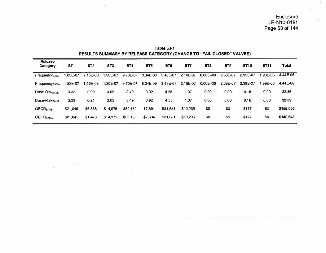
EnclosureLR-N10-0181
Page 63 of 144
Table 5.i-1
RESULTS SUMMARY BY RELEASE CATEGORY (CHANGE TO "FAIL CLOSED" VALVES)
ReleaseCategory ST1 ST2 ST3 ST4 ST5 ST6 ST7 ST8 ST9 ST1 0 ST1 1 Total
FrequencyBASE 1.83E-07 7.15E-08 1.30E-07 9.70E-07 8.34E-08 3.48E-07 2.16E-07 0.OOE+00 2.68E-07 2.39E-07 1.93E-06 4.44E-06
FrequencysAA 1.83E-07 1.53E-08 1.30E-07 9.70E-07 8.34E-08 3.48E-07 2.16E-07 0.OOE+00 2.68E-07 2.39E-07 1.99E-06 4.44E-06
Dose-RiskBAsE 3.33 0.99 3.05 8.49 0.92 4.55 1.37 0.00 0.00 0.16 0.00 22.86
Dose-RisksAMA 3.33 0.21 3.05 8.49 0.92 4.55 1.37 0.00 0.00 0.16 0.00 22.09
OECRBASE $21,045 $6,888 $14,975 $62,159 $7,694 $31,881 $10,235 $0 $0 $177 $0 $155,055
OECRSAMA $21,045 $1,476 $14,975 $62,159 $7,694 $31,881 $10,235 $0 $0 $177 $0 $149,643

EnclosureLR-N1 0-0181
Page 64 of 144
5.j The external events multiplier and review of potential seismic-related SAMAswere based on use of the Electric Power Research Institute (EPRI) seismichazard curve for HCGS (in contrast to the Lawrence Livermore NationalLaboratory (LLNL) seismic hazard curve used for Salem Generating StationSAMA analysis). It appears that use of the LLNL seismic hazard curve or U.S.Geological Survey 2008 seismic hazard data would result in larger estimatedbenefits for SAMAs, and possibly additional, potentially cost-beneficial SAMAsfor HCGS. Provide an assessment of the impact on the SAMA identification andscreening process if the seismic CDF and external event multiplier were basedon use of the LLNL seismic hazard curve rather than the EPRI curve.
PSEG Response:
Use of the LLNL seismic hazard curves in place of the EPRI curves will impactthe external events multiplier, the maximum averted cost-risk (MACR) for thesite, the depth of the internal events importance review, and potentially thenumber of fire and seismic contributors requiring review in the SAMAidentification process. Each of these issues must be re-assessed in order todetermine how the use of the LLNL seismic hazard curve impacts the HCGSSAMA identification process. The steps required to complete this task are asfollows:
0 Recalculate the seismic CDF.
* Recalculate the external events multiplier.
* Recalculate the MACR.
* Update the fire and seismic potential averted cost-risk (PACR) calculations.
* Identify the fire areas and seismic scenarios with PACR values greater than$100,000.
* Review any areas/scenarios that were not reviewed as part of the ER.
* Establish the new internal events importance list RRW review threshold basedon the updated MACR.
* Review any new events that fall above the RRW review threshold and identify
the SAMAs required to mitigate the risk associated with those events.
Recalculation of the Seismic CDF
The HCGS seismic CDF can be updated to reflect the LLNL seismic hazardcurves using the conditional core damage probability (CCDP) informationprovided in Section E.5.1.7.2 of the HCGS Environmental Report (ER) and theLLNL seismic hazard curve data provided in Table 3-7 of the HCGS IPEEE(PSEG 1997). Table 5j-1 summarizes the updated CDF values for each seismic-induced equipment damage states.

EnclosureLR-N1 0-0181
Page 65 of 144
Table 5j-1UPDATED HCGS SEISMIC RESULTS BASED ON THE LLNL SEISMIC HAZARD CURVES
BASIC SeismicHazard Seismic CDF % of SeismicEVENT DESCRIPTION F CCDPIDFrequency i(lyr) CDF
ID (/yr) (LLNL)
%IE- Seismic-Induced Equipment 2.50E-06 1.00E+00 2.50E-06 69.8%SET36 Damage State SET-36
(Impacts - 120V PNL481)%IE- Seismic-Induced Equipment 6.30E-05 5.20E-03 3.28E-07 9.1%
SET18 Damage State SET-18(Impacts - LOOP)
%IE- Seismic-Induced Equipment 4.40E-07 1.OOE+00 4.40E-07 12.3%SET37 Damage State SET-37
(Impacts - 125V)%IE- Seismic-Induced Equipment 1.60E-07 1.00E+00 1.60E-07 4.5%
SET35 Damage State SET-35(Impacts - 120V PNL482,RSP)
%IE- Seismic-Induced Equipment 5.40E-08 1.OOE+00 5.40E-08 1.5%SET38 Damage State SET-38
(Impacts - 1 E Panel RoomVentil.)
%IE- Seismic-Induced Equipment 3.80E-06 9.04E-03 3.44E-08 1.0%SET26 Damage State SET-26
(Impacts - LOOP, 250V)
%IE- Seismic-Induced Equipment 8.1 OE-07 1.04E-02 8.42E-09 0.2%SET09 Damage State SET-09
(Impacts - 250V)
%IE- Seismic-Induced Equipment 4.60E-08 1.00E+00 4.60E-08 1.3%SET34 Damage State SET-34
(Impacts - CR, RSP)
%IE- Seismic-Induced Equipment 6.70E-07 6.OOE-03 4.02E-09 0.1%SET28 Damage State SET-28
(Impacts - LOOP, 250V, CV)'%IE- Seismic-Induced Equipment 8.10E-07 6.00E-03 4.86E-09 0.1%
SET30 Damage State SET-30(Impacts - LOOP, 250V, CST)
%IE- Seismic-Induced Equipment 2.40E-07 1.00E-02 2.40E-09 0.1%SET27 Damage State SET-27
(Impacts - S2, LOOP, 250V)
%IE- Seismic-Induced Equipment 6.1OE-08 1.OOE-02 6.10E-10 0.0%SET13 Damage State SET-13
(Impacts - 250V, CST)
%IE- Seismic-Induced Equipment 6.00E-07 5.OOE-04 3.OOE-10 0.0%SET03 Damage State SET-03
(Impacts - CV)%IE- Seismic-Induced Equipment 5.80E-08 1.OOE-02 5.80E-10 0.0%
SET1 1 Damage State SET-i 1(Impacts - 250V, CV)
%IE- Seismic-Induced Equipment 1.60E-06 2.50E-04 4.OOE-10 0.0%SET20 Damage State SET-20
(Impacts - LOOP, CV)
II-Total= 3.58E-06
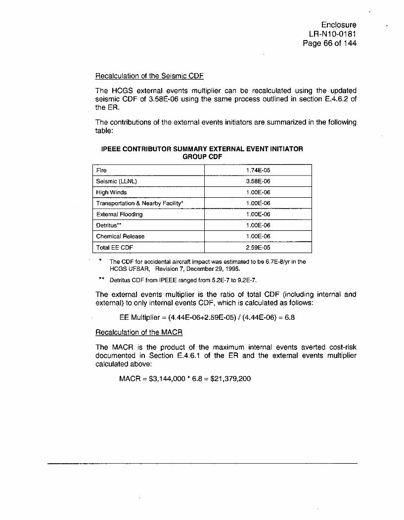
EnclosureLR-N1 0-0181
Page 66 of 144
Recalculation of the Seismic CDF
The HCGS external events multiplier can be recalculated using the updatedseismic CDF of 3.58E-06 using the same process outlined in section E.4.6.2 ofthe ER.
The contributions of the external events initiators are summarized in the followingtable:
IPEEE CONTRIBUTOR SUMMARY EXTERNAL EVENT INITIATOR
GROUP CDF
Fire 1.74E-05
Seismic (LLNL) 3.58E-06
High Winds 1.OOE-06
Transportation & Nearby Facility* 1.OOE-06
External Flooding 1.OOE-06
Detritus** 1.OOE-06
Chemical Release 1.OOE-06
Total EE CDF 2.59E-05
* The CDF for accidental aircraft impact was estimated to be 6.7E-8/yr in the
HCGS UFSAR, Revision 7, December 29, 1995.
** Detritus CDF from IPEEE ranged from 5.2E-7 to 9.2E-7.
The external events multiplier is the ratio of total CDF (including internal andexternal) to only internal events CDF, which is calculated as follows:
EE Multiplier = (4.44E-06+2.59E-05) / (4.44E-06) = 6.8
Recalculation of the MACR
The MACR is the product of the maximum internal events averted cost-riskdocumented in Section E.4.6.1 of the ER and the external events multipliercalculated above:
MACR = $3,144,000 * 6.8 = $21,379,200

EnclosureLR-N1 0-0181
Page 67 of 144
Update Fire and Seismic PACRs
The PACR values for each of the fire areas has been estimated by multiplyingthe MACR by the ratio of the CDF for the fire area to the total site CDF(4.44E-06 + 2.59E-05 = 3.03E-05/yr). As documented in Table 5j-2, no new fireareas require evaluation based on the use of the LLNL seismic hazard curves.All areas with PACRs greater than $100,000 were reviewed as part of the ERsubmittal.
Table 5j-2UPDATED FIRE CONTRIBUTOR SUMMARY
BASIC DESCRIPTION Freq. (/yr) CCDP IE CDF % of CompartmentEVENT ID (/yr) Fire Fire MACR
N DCDF%IE-FIRE03 Control Room Fire Scenario 2.94E-04 1.80E-02 5.292E-06 30.5% $3,733,951
Small Cab_3 (Loss of Emer.Bat.)
%IE-FIRE02 Control Room Fire Scenario 2.45E-04 1.80E-02 4.410E-06 25.4% $3,111,626Small Cab_2 (Loss ofSSWS)
%IE-FIRE01 Control Room Fire Scenario 2.10E-04 1.80E-02 3.780E-06 21.8% $2,667,108Small Cab 1 (Loss ofSACS)
%IE-FIRE28 Cmprtmnt 5339 Fire 1.25E-05 6.00E-02 7.500E-07 4.3% $529,188Scenario 5339 2
%IE-FIRE37 DG Room (D) Fire Scenario 1.00E-04 6.98E-03 6.980E-07 4.0% $492,4985304_2
%IE-FIRE20 DG Room (C) Fire Scenario 1.OOE-04 6.67E-03 6.670E-07 3.8% $470,6255306_2
%IE-FIRE38 Cmprtmnt 3425/5401 Fire 3.40E-05 1.72E-02 5.848E-07 3.4% $412,626Scenario 5401 1
%IE-FIRE06 Control Room Fire Scenario 2.55E-05 6.OOE-02 5.100E-07 2.9% $359,848Large Cab-l (MSIVClosure)
%IE-FIRE21 DG Room (B) Fire Scenario 4.00E-03 2.09E-05 8.360E-08 0.5% $58,9875305_1
%IE-FIRE24 Cmprtmnt 5501 Fire 4.20E-04 1.90E-04 7.980E-08 0.5% $56,306Scenario 5501 1

EnclosureLR-N1 0-0181
Page 68 of 144
For the seismic events, use of the LLNL seismic hazard curves resulted in theidentification of two additional scenarios with PACRs greater than $100,000. ThePACR for the next largest contributor is less than $60,000, as documented inTable 5j-3:
Table 5j-3UPDATED SEISMIC CONTRIBUTOR SUMMARY
BASIC DESCRIPTION Seismic CCDP Seismic % of CompartmentEVENT ID Hazard CDF (/yr) Seismic Seismic PACR
Frequency CDF(/yr) (LLNL)
%IE-SET36 Seismic-Induced 2.50E-06 1.00E+00 2.50E-06 69.8% $1,763,960Equipment Damage StateSET-36 (Impacts - 120VPNL481)
%IE-SET37 Seismic-Induced 4.40E-07 1.00E+00 4.40E-07 12.3% $310,457Equipment Damage StateSET-37 (Impacts - 125V)
%IE-SET18 Seismic-Induced 6.30E-05 5.20E-03 3.28E-07 9.1% $231,149Equipment Damage StateSET-18 (Impacts - LOOP)
%IE-SET35 Seismic-Induced 1.60E-07 1.00E+00 1.60E-07 4.5% $112,893Equipment Damage StateSET-35 (Impacts - 120VPNL482, RSP)
%IE-SET38 Seismic-Induced 5.40E-08 1.00E+00 5.40E-08 1.5% $38,102Equipment Damage StateSET-38 (Impacts - 1 EPanel Room Ventil.)
%IE-SET34 Seismic-Induced 4.60E-08 1.OOE+00 4.60E-08 1.3% $32,457Equipment Damage StateSET-34 (Impacts - CR,RSP)
%IE-SET26 Seismic-Induced 3.80E-06 9.04E-03 3.44E-08 1.0% $24,238Equipment Damage StateSET-26 (Impacts - LOOP,250V)
%IE-SET09 Seismic-Induced 8.1OE-07 1.04E-02 8.42E-09 0.2% $5,944Equipment Damage StateSET-09 (Impacts - 250V)
%IE-SET30 Seismic-Induced 8.10E-07 6.OOE-03 4.86E-09 0.1% $3,429Equipment Damage StateSET-30 (Impacts - LOOP,250V, CST)
%IE-SET28 Seismic-Induced 6.70E-07 6.OOE-03 4.02E-09 0.1% $2,836Equipment Damage StateSET-28 (Impacts - LOOP,250V, CV)

EnclosureLR-N10-0181
Page 69 of 144
Review/Evaluation of New Seismic Scenarios
%IE-SET37 - Seismic-Induced Equipment Damage State SET-37 (Impacts -125V): This scenario represents seismic-induced failure of 1 E power to all four125V DC distribution panels (1A/B/C/D-D-417). The IPEEE assumes aconditional core damage probability of 1.0 for these scenarios.
The seismic model does not credit local operation of the systems impacted bythis failure (e.g., Feedwater, RHR, CS, HPCI, RCIC, ADS). HCGS does have aprocedure to operate RCIC without AC or DC power; however, long term roomcooling issues (for local operator actions) and the limited time that is available toestablish local RCIC control preclude crediting the existing procedure for seismicevents.
A potential means of addressing the %IE-SET37 risk would be to reinforce the125V DC panel anchorages, but even if 125V DC panel failures could beeliminated, other equipment failures would limit the benefit of this enhancement.For example, the HCLPF value listed for these panels in Table 3-5 of the HCGSIPEEE is 0.57g, which is substantially greater than the 0.33g value of the 120VAC panels that are addressed as part of SAMA 37. The implication is that even ifthe 125V DC panels were enhanced, the operators would be required to operatethe plant without 120V AC power. The IPEEE does not credit operation of theplant without 120V AC power; however, for this evaluation, it is assumed that theoperators would be successful 50 percent of the time. It follows that the plantcould be controlled for half of the cases in which failure of the 125V DC panels isprevented through anchorage enhancement. Based on this assumption, thePACR for %IE-SET37 would be 50 percent of its original value assuming that the125V DC panel enhancements always preclude seismically induced failure($310,457 * 0.5 = $155,229). Using the 9 5 th percentile PRA results, this PACRcould be increased by a factor of 2.84 to $440,850.
Given the relatively high HCLPF value for the 125V DC panels, designing andimplementing a means of reinforcing them so that they are significantly morerobust would likely cost more than the changes proposed for the 1A/B/C/DJ481panels in SAMA 37; however, the $500,000 implementation cost is assumed tobe applicable for this evaluation. Even when this potentially low cost ofimplementation is used with the 9 5 th percentile PRA results, reinforcing the1A/B/C/D-D-417 125V DC panels would not be cost effective, as shown below:
Net Value = $440,850 - $500,000 = -$59,150
%IE-SET35 - Seismic-Induced Equipment Damage State SET-35 (Impacts -120V PNL482, RSP): This scenario represents a seismic-induced failure of allfour divisions of 1 E 120V AC instrumentation distribution panels (1A/B/C/DJ482panels) and subsequent failure to control the plant manually (without automatedactuation from the associated logic circuits).

EnclosureLR-N1 0-0181
Page 70 of 144
If all four of the 120V AC J482 panels fail, operator action can still prevent coredamage. The 1 A/B/C/DJ482 panels distribute 120V 1 E AC power to various 1 Elogic cabinets. The failure of these logic cabinets causes a substantial loss ofautomatic actuation of 1 E equipment, including diesel generator load sequencingand automatic Primary Containment Isolation System signals. However, manualoperation of this equipment and manual diesel generator loading is still possible(e.g., at the Remote Shutdown Panel), and procedural guidance is available.
Enhancements could be made to align alternate power sources directly to logicloads using portable generators; however, human dependence issues would limitthe credit of any SAMA requiring operator action. In these scenarios, theoperators have procedures to manually operate equipment in the main controlroom to address the loss of 120V AC power; if they fail to perform these relativelysimple actions, it would be difficult to justify credit for additional actions tomitigate the same scenario.
A potential means of mitigating these scenarios is to reinforce the distributionpanels, as proposed in SAMA 37 for panels 1A/B/C/DJ481. Given that the ERlists cost of implementation as $500,000, this SAMA would not be cost effectiveeven if it were capable of eliminating all risk associated with %IE-SET35, asshown below:
Net Value = $112,893 - $500,000 = -$387,107
For the 9 5 th percentile PRA sensitivity, the PACR is increased by a factor of 2.84to $320,616, which is still less than the cost of implementation.
Establish the New Internal Events Importance List RRW Review Threshold:
Because the MACR has increased, the depth of the importance list review mustalso be increased given that lower contributors to risk correlate to higher potentialaverted cost-risk values. Based on the new MACR of $21,379,200, the RRWthreshold value is reduced from 1.006 to 1.005, which correlates to a cost ofabout $106,000.
Review of New Internal Events Contributors
Table 5j-4 provides a review of the Level 1 events with RRW values of 1.005,which resulted in the identification of only one additional SAMA:
* SAMA RAI5j-IE1: Install a keylock switch for bypass of MSIV low levelisolation logic
For ATWS events, level/power control guidance may require the operators toreduce level below -129", which normally results in closure of the MSIVs. Inorder to maintain the condenser as a heat sink, it is necessary to bypass theisolation logic. Given the complexity of the bypass action and the limited timethat is available to perform the bypass, the reliability of the action is currently low.If the bypass action were simplified to the degree where it could be performed bymanipulation of a keylock switch, the action's reliability could be improved andthe ATWS contribution would be reduced.

EnclosureLR-N10-0181
Page 71 of 144
Installation of a similar logic bypass scheme was proposed as SAMA 40 at a costof $620,000. This implementation cost is considered to be a reasonablerepresentation of the control change proposed for SAMA RAI5j-IE1.
Given that HCGS events at the 1.005 RRW level correlate to only $301,040 withthe 95th percentile results, this type of SAMA would not be cost effective.
The Level 2 review is provided in the response to RAI 5.p.
REFERENCES
PSEG 1997 PSEG (Public Service Electric and Gas Company). 1997. HopeCreek Generating Station Individual Plant Examination ofExternal Events. July.
5.k Table E.5-3 includes 23 Phase 1 SAMAs numbered from 1 through 40. Themissing numbers were presumably identified early in the process and discardedfor some reason. Provide further information on the development of the Phase 1SAMA list, the numbering of the SAMA candidates, and any candidates screenedout prior to this list.
PSEG Response:
An importance list was initially reviewed for identification of SAMAs using theHC108A model, but after the development of the HC108B PRA model, a newimportance list was reviewed and certain SAMAs that were previously identifiedusing the HC108A model were found to either no longer be applicable or weresubsumed into other existing SAMAs. However, the SAMAs were notrenumbered so as to avoid any configuration errors with other documentationand supplemental files, such as those used for calculating the SAMAimplementation costs and averted cost-risks. SAMAs that were identified as aresult of the external events review were given a starting number of 30 so as toavoid any possible overlap with the numbers used for SAMAs identified duringthe internal events review.

EnclosureLR-N10-0181
Page 72 of 144
5.1 It appears that the SAMA identification process eliminated many potentialSAMAs by not explicitly considering the generic list of SAMAs included in NEI 05-01 and by using the excessive implementation cost criteria in screening the PRAimportance lists (see RAI 5.f). Justify that the Phase 1 SAMA identification andscreening process has produced a comprehensive and sufficiently complete setof SAMAs for consideration, given that 13 of the 23 Phase 1 SAMAs wereultimately determined to be potentially cost-beneficial.
PSEG Response:
One of the reasons that the NEI 05-01 guidance was developed was to move theindustry toward a SAMA identification process that was based on plant-specificrisks. The development of the guidance was initiated after the NRC review of theH.B. Robinson SAMA analysis. During this review, the NRC explicitly stated thata review of a generic SAMA list was of limited benefit; the generic SAMAs hadbeen analyzed by multiple plants and were consistently found not to be costbeneficial. The real benefit was considered to be in the development of SAMAsgenerated from plant-specific risk insights. The Hope Creek SAMA identificationprocess is consistent with this philosophy given that it is based on plant-specificrisk insights from the PRA models.
In addition, the generic SAMA list provided in NEI 05-01 has no intrinsic value.The list was derived from the body of SAMAs identified from previous SAMAsubmittals and other industry guidance (with duplicates deleted). There is noguarantee that the list of SAMAs is in any way comprehensive or that it is evenrelevant to any given plant beyond the fact that it includes potential plantenhancements that may have been derived from similar plants.
If the generic NEI 05-01 SAMA list were to be explicitly evaluated in a usefulmanner, each of the proposed SAMAs would have to be reviewed and thenmodified/extrapolated to match the systems or functions of the plant underconsideration; otherwise, a large majority of the SAMAs would be screened asnot being relevant to the plant. Even after modifying the SAMA so that it isrelevant to the plant's systems/functions, further changes would be required toensure that the SAMA would address the spectrum of risk relevant to the plantrather than just a portion of the risk. For example, SAMA 136 from Table 13 ofNEI 05-01 is a SAMA to "Enhance procedures to use alternate shutdownmethods if the control room becomes uninhabitable," which are already in placeat Hope Creek. If effort is not expended to consider the SAMA in the context ofthe plant, it would be screened as "already implemented". In order to make thisSAMA relevant to Hope Creek, it would have to be modified to suggestdeveloping procedures to address scenarios in which fires in other plant areasdamage critical controls in the MCR. For these cases, procedure enhancementsto allow the partial transfer of control to the alternate shutdown panel would behelpful. Obviously, SAMA 136 from Table 13 of NEI 05-01 would serve only asan idea source in a process to develop a SAMA that is relevant to the HopeCreek design, operation, and plant-specific risk factors.
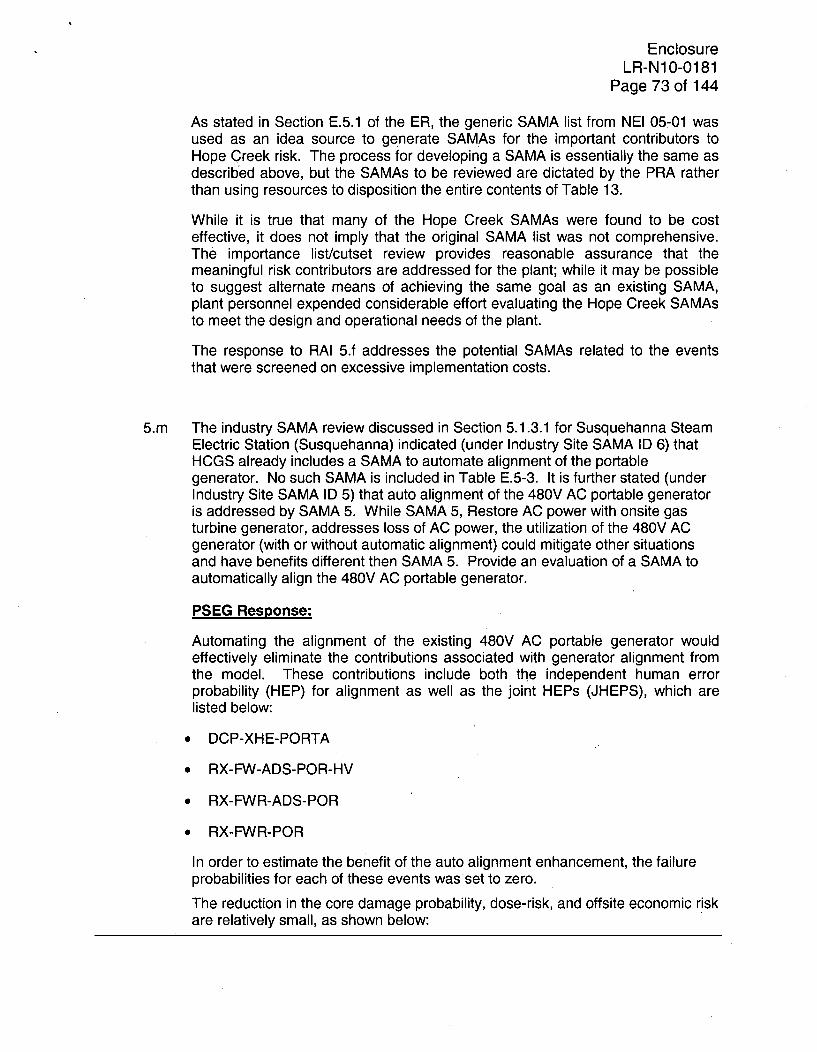
EnclosureLR-N1O-0181
Page 73 of 144
As stated in Section E.5.1 of the ER, the generic SAMA list from NEI 05-01 wasused as an idea source to generate SAMAs for the important contributors toHope Creek risk. The process for developing a SAMA is essentially the same asdescribed above, but the SAMAs to be reviewed are dictated by the PRA ratherthan using resources to disposition the entire contents of Table 13.
While it is true that many of the Hope Creek SAMAs were found to be costeffective, it does not imply that the original SAMA list was not comprehensive.The importance list/cutset review provides reasonable assurance that themeaningful risk contributors are addressed for the plant; while it may be possibleto suggest alternate means of achieving the same goal as an existing SAMA,plant personnel expended considerable effort evaluating the Hope Creek SAMAsto meet the design and operational needs of the plant.
The response to RAI 5.f addresses the potential SAMAs related to the eventsthat were screened on excessive implementation costs.
5.m The industry SAMA review discussed in Section 5.1.3.1 for Susquehanna SteamElectric Station (Susquehanna) indicated (under Industry Site SAMA ID 6) thatHCGS already includes a SAMA to automate alignment of the portablegenerator. No such SAMA is included in Table E.5-3. It is further stated (underIndustry Site SAMA ID 5) that auto alignment of the 480V AC portable generatoris addressed by SAMA 5. While SAMA 5, Restore AC power with onsite gasturbine generator, addresses loss of AC power, the utilization of the 480V ACgenerator (with or without automatic alignment) could mitigate other situationsand have benefits different then SAMA 5. Provide an evaluation of a SAMA toautomatically align the 480V AC portable generator.
PSEG Response:
Automating the alignment of the existing 480V AC portable generator wouldeffectively eliminate the contributions associated with generator alignment fromthe model. These contributions include both the independent human errorprobability (HEP) for alignment as well as the joint HEPs (JHEPS), which arelisted below:
* DCP-XHE-PORTA
* RX-FW-ADS-POR-HV
* RX-FWR-ADS-POR
0 RX-FWR-POR
In order to estimate the benefit of the auto alignment enhancement, the failureprobabilities for each of these events was set to zero.
The reduction in the core damage probability, dose-risk, and offsite economic riskare relatively small, as shown below:

EnclosureLR-N10-0181
Page 74 of 144
PRA RESULTS SUMMARY FOR AUTOMATING PORTABLEGENERATOR ALIGNMENT
CDF Dose-Risk OECR
Base Value 4.44E-06 22.86 $155,055
SAMA Value 4.17E-06 22.69 $153,810Percent Change 6.1% 0.7% 0.8%
A further breakdown of the dose-risk and OECR information is provided in theTable 5.m-1 according to release category.
The PRA results were used as input to the cost benefit calculation using themethodology documented in Section E.4 of the HCGS Environmental Report andthe revised external events multiplier of 6.8 that was derived in the response toRAI 5.j. The results of this calculation are provided in the following table:
AVERTED COST-RISK FOR AUTOMATING PORTABLEGENERATOR ALIGNMENT
Base Case Revised AvertedCost-Risk Cost-Risk Cost-Risk
Hope Creek $21,379,200 $21,166,231 $212,969
Using the 9 5 th percentile PRA results, the averted cost-risk would be $604,832.
The cost of automating the alignment of the 480V AC generator is estimatedbased on other industry enhancements for similar changes. TMI SAMA 1(Exelon 2008) estimated the cost of automating the start and load of an existing,permanently installed 4KV AC generator to be $3,125,000. For HCGS, theportable generator would have to be permanently installed/housed in addition toadding the logic to perform the auto start and load function.
SAMA 1 from the Shearon Harris License Renewal Environmental Report(Progress Energy 2006) does not address auto start and load of a portable 480VAC generator, but it does include permanently mounting a 480V AC generatorand the plant's hydrostatic test pump so that they could be rapidly aligned tosupport reactor coolant pump seal injection. The cost of implementation forShearon Harris SAMA 1 was estimated to be $1 million.
Neither of the SAMAs identified above are exact matches for the enhancementproposed in this RAI, but they demonstrate that automating alignment of a powersource and permanently mounting a 480V AC generator for rapid responserepresent significant monetary investments.

EnclosureLR-N10-0181
Page 75 of 144
Assuming that automating the HCGS 480V AC generator could be performed forthe lesser of these two costs, this enhancement would not be cost beneficialeven when the 9 5 th percentile PRA results are applied:
Net Valueg5 th Percentile PRA Results = $604,832 - $1,000,000 = -$395,168
REFERENCES
Exelon 2008 Exelon Generation Company, LLC (Exelon). 2008. Applicant'sEnvironmental Report; Operating License Renewal Stage;Three Mile Island Unit 1. Appendix E - Severe AccidentMitigation Alternatives Analysis. January.
Progress Energy 2006 Progress Energy. 2006. Applicant's Environmental Report;Operating License Renewal Stage; Shearon Harris NuclearPlant. Appendix E - Severe Accident Mitigation AlternativesAnalysis. November.
5.n Table E.5-3 indicates that SAMA 38, Enhance FWS and ADS for long-terminjection, was screened out on the basis that a procedure has been implementedto address the actions associated with this SAMA. However, as discussed inSection E.5.1.7.2.2, this SAMA requires enhancement to the feedwater system(FWS), including strengthening the fire water tanks. It is not clear whether/howenhancements to the FWS have been addressed as part of the implementationof the current procedure. Provide additional discussion regarding this SAMA.
PSEG Response:
HCGS procedure HC.OP-AM.TSC-0024 does provide guidance for using the firewater system and the portable generator for long term RPV injection, asindicated in Table E.5-3 of the ER; however, the physical enhancementsassociated with SAMA 38 were not performed. Specifically, Section E.5.1.7.2.2indicates that the fire water tanks may have to be reinforced to ensure that theywould be available. Other enhancements might also include:
* Providing a seismically qualified storage area for the portable generator, and
* Providing a seismically qualified 24-hour fuel source (gasoline) for the portablegenerator.
SAMA 38 was developed based on a review of Seismic Induced EquipmentDamage State SET 18 (%IE-SET18), which represents a seismically inducedLOOP without any additional seismically induced equipment failures. Theimplication is that the fire water tanks would remain intact and that no changes tothe system would be required to address %IE-SET18 (procedure HC.OP-

EnclosureLR-N1 0-0181
Page 76 of 144
AM.TSC-0024 is adequate alone). Given that the high confidence, lowprobability of failure (HCLPF) value of the offsite power system is relatively low(0.1g PGA) compared with that of the firewater tanks (0.26g PGA), this is notunreasonable.
For the remaining scenarios, other seismically induced failures have occurred inaddition to loss of offsite power. These scenarios generally represent moresevere seismic events and it is assumed that the physical enhancementsidentified above would be required to help ensure the fire water system andportable generator would be available. For the scenarios including loss of the120V AC distribution equipment, which the response to RAI 5.j indicates are thelargest seismic contributors, SAMAs 36 and 37 are considered to be moreappropriate and cost effective enhancements. This is based on the GE ABWRTechnical Support Document that estimated the cost of a seismically qualifiedCST to be $1,000,000 (GE 1994). This estimate does not account for any costsassociated with providing a seismically qualified storage area or 24-hour fuelsource.
The other major contributors include failure of the 125V and 250V DC systems.HCGS currently has procedures to operate RCIC without AC or DC power, whichwas not credited in the seismic analysis.
In summary, the design of SAMA 38 included potential enhancements to the FireWater System that were subsequently determined not to be required. Thescenarioon which SAMA 38 is based is a low magnitude seismic event that wouldnot challenge the fire water tanks such that the existing HCGS guidance issufficient to mitigate the event. Enhancing the Fire Water system and theportable generator would allow them to be used to mitigate some of the moresevere seismic events, but these scenarios are considered to be betteraddressed by other SAMAs or can be addressed by existing HCGS proceduresthat are currently not credited in the seismic model.
REFERENCES
GE 1994 GE Nuclear Energy (GE). 1994. Technical Support Document forthe ABWR. 25A5680 Rev. 1. November.
5.o Table E.5-3 indicates that SAMA 14, Alternate room cooling for SW rooms,originated from the HCGS Level 1 importance list. Identify the basic event(s) thatis the source for this SAMA. Based on the description of this SAMA - to providealternate means of opening Torus Vent Valves - it is not clear how the SAMArelates to providing alternate room cooling for SW rooms. Explain thisdiscrepancy. Also, this SAMA was subsumed into SAMA 4 and subsequently notretained for the Phase 2 evaluation. Clarify the logic for subsuming this SAMAinto SAMA 4.

EnclosureLR-N1 0-0181
Page 77 of 144
The events that were originally associated with SAMA 14 are related tocontainment venting failure (CAC-SOV-CC-1 1541 and CAC-SOV-CC-4964).The HCGS PRA model conservatively does not credit the local venting action forthese types of failures; however, the action is applicable. If credit is taken for thelocal venting action, the cutsets including CAC-SOV-CC-1 1541 and CAC-SOV-CC-4964 are essentially eliminated and no SAMAs are required.
The disposition of events CAC-SOV-CC-1 1541 and CAC-SOV-CC-4964 evolvedduring the development of the SAMA analysis to address the differentcontributors that are linked with the CAC-SOV-CC-1 1541 and CAC-SOV-CC-4964 events. The approaches to dispositioning these contributors included:
* Providing an alternate room cooling strategy to address failure of the ServiceWater Pump Room fans (these HVAC failures result in loss of containmentheat removal and ultimately require containment venting).
* Directly addressing remote vent valve failures by "proceduralizing" localoperator actions.
" Mitigating the RHR failures that lead to the need to perform containmentventing (loss of RHR requires containment venting as an alternate heatremoval strategy). These RHR failures are linked to event RHS-REPAIR-TR,which is included in all cutsets containing events CAC-SOV-CC-1 1541 andCAC-SOV-CC-4964. SAMA 4 was developed to address event RHS-REPAIR-TR.
The title of SAMA 14, as documented in Table E.5-3 of the ER, is "Alternate roomcooling for SW Rooms". This title was based on the strategy to address theService Water Pump Room HVAC fan failures. The approach was to useportable fans to provide alternate room cooling.
The description of SAMA 14, which was not updated to match the title in TableE.5-3 of the ER, is "Provide an alternate means of opening the Torus vent valveswhen remote operation fails. Adequate time is available given this is a long termsequence." This description was based on the strategy to address the vent valvefailures with procedures for the local venting action.
As the SAMA analysis progressed, it was decided that SAMA 4 was the mostappropriate means of addressing the scenarios including events CAC-SOV-CC-11541 and CAC-SOV-CC-4964. Table E.5-1 was updated to reflect this, butSAMA 14 was retained in Table E.5-3 with a comment that it had beensubsumed by SAMA 4.
There are other contributors to Service Water Pump Room HVAC failures,however, that could be addressed by an alternate room cooling strategy. SAMAs17 and 18 represent potential enhancements to mitigate these contributors thatwere determined to be cost effective, but implementation of an alternate roomcooling strategy similar to what is in place for the Switchgear Rooms may be amore practical and cost effective solution. This is addressed in the response toRAI 7.a.
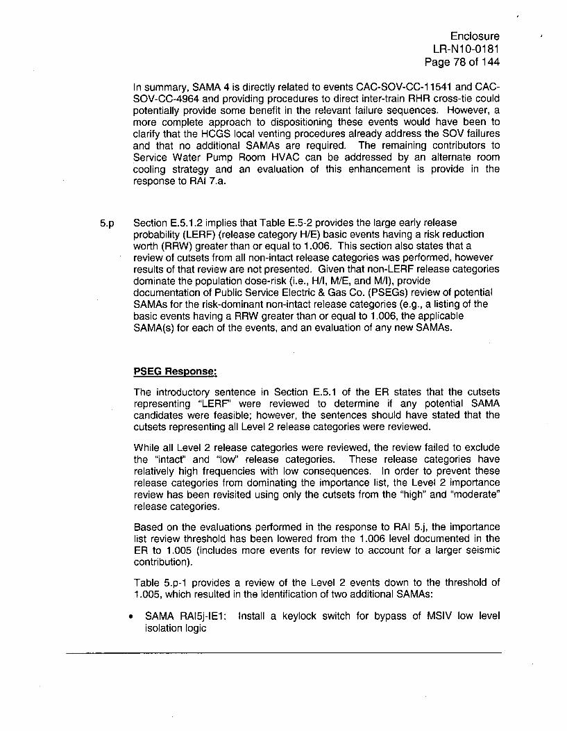
EnclosureLR-N10-0181
Page 78 of 144
In summary, SAMA 4 is directly related to events CAC-SOV-CC-1 1541 and CAC-SOV-CC-4964 and providing procedures to direct inter-train RHR cross-tie couldpotentially provide some benefit in the relevant failure sequences. However, amore complete approach to dispositioning these events would have been toclarify that the HCGS local venting procedures already address the SOV failuresand that no additional SAMAs are required. The remaining contributors toService Water Pump Room HVAC can be addressed by an alternate roomcooling strategy and an evaluation of this enhancement is provide in theresponse to RAI 7.a.
5.p Section E.5.1.2 implies that Table E.5-2 provides the large early releaseprobability (LERF) (release category H/E) basic events having a risk reductionworth (RRW) greater than or equal to 1.006. This section also states that areview of cutsets from all non-intact release categories was performed, howeverresults of that review are not presented. Given that non-LERF release categoriesdominate the population dose-risk (i.e., H/I, M/E, and M/1), providedocumentation of Public Service Electric & Gas Co. (PSEGs) review of potentialSAMAs for the risk-dominant non-intact release categories (e.g., a listing of thebasic events having a RRW greater than or equal to 1.006, the applicableSAMA(s) for each of the events, and an evaluation of any new SAMAs.
PSEG Response:
The introductory sentence in Section E.5.1 of the ER states that the cutsetsrepresenting "LERF" were reviewed to determine if any potential SAMAcandidates were feasible; however, the sentences should have stated that thecutsets representing all Level 2 release categories were reviewed.
While all Level 2 release categories were reviewed, the review failed to excludethe "intact' and "low" release categories. These release categories haverelatively high frequencies with low consequences. In order to prevent theserelease categories from dominating the importance list, the Level 2 importancereview has been revisited using only the cutsets from the "high" and "moderate"release categories.
Based on the evaluations performed in the response to RAI 5.j, the importancelist review threshold has been lowered from the 1.006 level documented in theER to 1.005 (includes more events for review to account for a larger seismiccontribution).
Table 5.p-1 provides a review of the Level 2 events down to the threshold of1.005, which resulted in the identification of two additional SAMAs:
* SAMA RAI5j-IE1: Install a keylock switch for bypass of MSIV low levelisolation logic
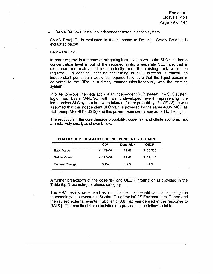
EnclosureLR-N10-0181
Page 79 of 144
SAMA RAI5p-1: Install an independent boron injection system
SAMA RAI5j-IE1 is evaluated in the response to RAI 5.j. SAMA RAI5p-1 isevaluated below.
SAMA RAI5p-1
In order to provide a means of mitigating instances in which the SLC tank boronconcentration level is out of the required limits, a separate SLC tank that ismonitored and maintained independently from the existing tank would berequired. In addition, because the timing of SLC injection is critical, anindependent pump train would be required to ensure that the liquid poison isdelivered to the RPV in a timely manner (simultaneously with the existingsystem).
In order to model the installation of an independent SLC system, the SLC systemlogic has been "AND"ed with an undeveloped event representing theindependent SLC system hardware failures (failure probability of 1.0E-03). It wasassumed that the independent SLC train is powered by the same 480V MCC asSLC pump AP208 (110B212) and this power dependency was added to the logic.
The reduction in the core damage probability, dose-risk, and offsite economic riskare relatively small, as shown below:
PRA RESULTS SUMMARY FOR INDEPENDENT SLC TRAINCDF Dose-Risk OECR
Base Value 4.44E-06 22.86 $155,055
SAMA Value 4.41 E-06 22.42 $152,144
Percent Change 0.7% 1.9% 1.9%
A further breakdown of the dose-risk and OECR information is provided in theTable 5.p-2 according to release category.
The PRA results were used as input to the cost benefit calculation using themethodology documented in Section E.4 of the HCGS Environmental Report andthe revised external events multiplier of 6.8 that was derived in the response toRAI 5.j. The results of this calculation are provided in the following table:

EnclosureLR-N10-0181
Page 80 of 144
AVERTED COST-RISK FOR INDEPENDENT SLC TRAIN
Base Case Revised AvertedCost-Risk Cost-Risk Cost-Risk
Hope Creek $21,379,200 $20,984,616 $394,584
With regard to the cost of implementation, Browns Ferry estimated the cost ofinstalling a redundant train of SLC to be $1,000,000 (TVA 2003). In order toaccount for the requirement to install an additional SLC tank and to maintain it amanner that is independent of the existing tank, the cost of implementation hasbeen increased by 50 percent to $1.5 million.
The net value of the change proposed in this RAI is the difference between theaverted cost-risk and the cost of implementation:
Net Value = $394,584 - $1,500,000 = -$1,105,416
The large, negative net value indicates that this SAMA is not cost beneficial.Even if the 9 5 th percentile PRA results are used in conjunction with an externalevents multiplier of 6.8, the net value is still negative:
Net Value95 th percentile PRA Results " ($394,584 * 2.84) - $1,500,000 = -$379,381
REFERENCES
TVA 2003 Tennessee Valley Authority (TVA). 2003. Applicant'sEnvironmental Report; Operating License Renewal Stage; BrownsFerry Nuclear Power Plant, Units 1, 2, and 3. Attachment E-4,Severe Accident Mitigation Alternatives at the Browns FerryNuclear Plant, Volume I of Ill. Application for Renewed OperatingLicenses. December.

EnclosureLR-N1 0-0181
Page 81 of 144
Table 5.p-1DISPOSITION OF RISK DOMINANT LEVEL 2 CONTRIBUTORS
Event Name Probability Risk Description Addressed Comments or Potential SAMAsReduction in ER Table
Worth E.5-2?CGS-PHE-FF-INERT 9.90E-01 6.244 CONTAINMENT INERTED; VENTING NOT Y
REQUIREDRX-NOCREDIT 1.OOE+00 3.513 FAILURE OF IN-VESSEL RECOVERY YCNT-MDL-FF-SCTRM 1.OOE+00 2.755 REACTOR BUILDING INEFFECTIVE IN Y
REDUCING SOURCE TERMCNT-MDL-FF-LVL1F 1.OOE+00 2.153 LG CONT. FAILURE GIVEN CONT. FAILED IN Y
LEVEL 1 (CLASS II, IID, IV)CNT-DWV-FF-MLTFL 1.OOE+00 2.124 DW SHELL MELT-THROUGH FAILURE DUE Y
TO CONT. FAILUREDIA 9.78E-01 1.746 DRYWELL FAILURE (CLASS IIA) YOP6-IIA-NOT 8.80E-01 1.6 RPV DEPRESSURIZATION SUCCESSFUL Y
(IIA)RHS-REPAIR-TR 3.50E-01 1.592 REPAIR/RECOVERY OF RHR FOR LOSS OF N Not addressed in Table E.5-2 of the
DHR EVENTS (TRANSIENT EVENTS) ER, but it was addressed in TableE.5-1. No additional SAMAs required.
ADS-XHE-OK-INHIB 1.OOE+00 1.285 OPERATOR SUCCESSFULLY INHIBITS ADS N Not addressed in Table E.5-2 of theWITH NO HP INJECTION (NON-ATWS) ER, but it was addressed in Table
E.5-1. No additional SAMAs required.%IE-SWS 1.79E-04 1.27 LOSS OF SERVICE WATER INITIATING N Not explicitly addressed in the Tables
EVENT E.5-1 or E.5-2 of the ER, but thisinitiating event it is tied directly toevent NR-IE-SWS, which wasaddressed in Table E.5-1 of the ER.The response to RAI 5b discusses thedisposition of NR-IE-SWS withSAMAs 1, 4, 15, and credit for localvalve operation.
NR-IE-SWS 1.OOE+00 1.27 NONRECOVERY OF %IE-SWS N This event was addressed in TableE.5-1 of the ER. The response to RAI5b discusses the disposition of NR-IE-SWS with SAMAs 1,4,15, and creditfor local valve operation.
EnclosureLR-N10-0181
Page 82 of 144
Table 5.p-1DISPOSITION OF RISK DOMINANT LEVEL 2 CONTRIBUTORS
Event Name Probability Risk Description Addressed Comments or Potential SAMAsReduction in ER Table
Worth E.5-2?%IE-TE 2.37E-02 1.221 LOSS OF OFFSITE POWER INITIATING N Not addressed in Table E.5-2 of the
EVENT ER, but it was addressed in TableE.5-1. No additional SAMAs required.
LOOP-IE-SW 2.10E-01 1.189 COND. PROBABILITY DUE TO WEATHER N Not addressed in Table E.5-2 of theRELATED LOOP EVENT ER, but it was addressed in Table
E.5-1. No additional SAMAs required.FC5-3B-NOT 5.90E-01 1.161 CONTAINMENT FLOODING INITIATED (IIIB) N The event was included, but no SAMA
was identified. Over 80% of thecontribution is driven by failure todepressurize, which is addressed bySAMA 1. No additional SAMAsrequired.
NR-U1X-DEP-SRV 3.OOE-04 1.139 FAILURE TO DEPRESSURIZE WITH SRV W/O N Not addressed in Table E.5-2 of theHIGH PRES. INJ. ER, but it was addressed in Table
E.5-1. No additional SAMAs required.OSPR20HR-SW 1.33E-01 1.128 FAILURE TO RECOVER OSP WITHIN 20 HRS N Not addressed in Table E.5-2 of the
(SW RELATED LOOP EVENT) ER, but it was addressed in TableE.5-1. No additional SAMAs required.
1RXRX-ONEACL-F-- 1.OOE+00 1.123 ONSITE EMERGENCY AC POWER NOT YRECOVERED
OP5-NOT 8.80E-01 1.12 RPV DEPRESSURIZATION SUCCESSFUL N The event was included, but no SAMAwas identified. Over 99.9% of thescenarios including this event includefailure to restore onsite AC power.SAMA 5 would address most of thesecases.
1 RXRX-OFFACL-F-- 6.OOE-01 1.12 OFFSITE AC POWER NOT RECOVERED Y%IE-MS 1.46E+00 1.12 MANUAL SHUTDOWN INITIATING EVENT N The event was included in Table E.5-
1, but no SAMA was identified. Theresponse to RAI 5a identifies that this
* initiating event includes a diverse setof contributors that are addressed byseveral SAMAs, including ( 1, 4, 16,17, and 18). No additional SAMAsrequired.

EnclosureLR-N10-0181
Page 83 of 144
Table 5.p-1DISPOSITION OF RISK DOMINANT LEVEL 2 CONTRIBUTORS
Event Name Probability Risk Description Addressed Comments or Potential SAMAsReduction in ER Table
Worth E.5-2?%IE-TT 7.03E-01 1.111 TURBINE TRIP WITH BYPASS N Not addressed in Table E.5-2 of the
ER, and no specific SAMA wasidentified for the event in Table E.5-1.The response to RAI 5a identifies thatthis initiating event includes a diverseset of contributors that are addressedby several SAMAs, including ( 1, 17,and 18). No additional SAMAsrequired.
%IE-S2-WA 6.20E-04 1.108 SMALL LOCA - WATER (BELOW TAF) N Not addressed in Table E.5-2 of theER, and no specific SAMA wasidentified for the event in Table E.5-1.The response to RAI 5a identifies thatthe contributors including this initiatingevent are addressed by SAMA 1. Noadditional SAMAs required.
NR-S1X-DEP-SRV 3.20E-02 1.104 FAILURE TO MAN. DEPRESS. FOR A MED. N Not addressed in Table E.5-2 of theLOCA W/NO HI PRESS. INJ. ER, and no specific SAMA was
identified for the event in Table E.5-1.The contributors including this eventare addressed by SAMA 1. Noadditional SAMAs required.

EnclosureLR-N10-0181
Page 84 of 144
Table 5.p-1DISPOSITION OF RISK DOMINANT LEVEL 2 CONTRIBUTORS
Event Name Probability Risk Description Addressed Comments or Potential SAMAsReduction in ER Table
Worth E.5-2?1OPPH-PRESBK-F-- 8.OOE-01 1.098 PRESSURE TRANSIENT DOES NOT FAIL N The event was included in Table E.5-
MECHANICAL SYSTEMS 2, but no SAMA was identified. About32% of the contribution is related toremote failures of valves HV-4964 orHV-1 1541. The PRA modelconservatively does not credit thelocal venting action to bypass thesefailures, but the action is applicable.An additional 23% of the contributorsconservatively do not credit localcontainment vent in long term SBOscenarios with portable generator anddiesel fire injection success, butagain, local venting is applicable.About 10% of the remaining diverseset of contributors can be addressedby simplifying the alignment of the gasturbine (SAMA 5). No additionalSAMAs required.

EnclosureLR-N1O-0181
Page 85 of 144
Table 5.p-1DISPOSITION OF RISK DOMINANT LEVEL 2 CONTRIBUTORS
Event Name Probability Risk Description Addressed Comments or Potential SAMAsReduction in ER Table
Worth E.5-2?1OPPH-SORV---F-- 5.50E-01 1.098 SRVs DO NOT FAIL OPEN DURING CORE N The event was included in Table E.5-
MELT PROGRESSION 2, but no SAMA was identified. About32% of the contribution is related toremote failures of valves HV-4964 orHV-1 1541. The PRA modelconservatively does not credit thelocal venting action to bypass thesefailures, but the action is applicable.An additional 23% of the contributorsconservatively do not credit localcontainment vent in long term SBOscenarios with portable generator anddiesel fire injection success, butagain, local venting is applicable.About 10% of the remaining diverseset of contributors can be addressedby simplifying the alignment of the gasturbine (SAMA 5). No additionalSAMAs required.

EnclosureLR-N10-0181
Page 86 of 144
Table 5.p-1DISPOSITION OF RISK DOMINANT LEVEL 2 CONTRIBUTORS
Event Name Probability Risk Description Addressed Comments or Potential SAMAsReduction in ER Table
Worth E.5-2?1OPPH-TEMPBK-F-- 7.OOE-01 1.098 HIGH PRIM SYS TEMP DOES NOT CAUSE N The event was included in Table E.5-
FAIL OF RCS PRESS. BOUND 2, but no SAMA was identified. About32% of the contribution is related toremote failures of valves HV-4964 orHV-11541. The PRA modelconservatively does not credit thelocal venting action to bypass thesefailures, but the action is applicable.An additional 23% of the contributorsconservatively do not credit localcontainment vent in long term SBOscenarios with portable generator anddiesel fire injection success, butagain, local venting is applicable.About 10% of the remaining diverseset of contributors can be addressedby simplifying the alignment of the gasturbine (SAMA 5). No additionalSAMAs required.
OP--XHE-ALT-DEP 1.00E+00 1.098 ALTERNATE DEPRESS. METHODS NOT Y The event was included in Table E.5-CREDITED 2, and SAMA 4 was suggested. The
recovery of heat removal is a largecontributor for these cases andproviding RHR X-tie guidance couldpotentially address these scenarios.However, this event is included in thesame scenarios as events 1 OPPH-TEMPBK-F--, 1OPPH-PRESBK-F--,and 1OPPH-SORV---F-- and thesame insights are applicable. Noadditional SAMAs required.

EnclosureLR-N1 0-0181
Page 87 of 144
Table 5.p-1DISPOSITION OF RISK DOMINANT LEVEL 2 CONTRIBUTORS
Event Name Probability Risk Description Addressed Comments or Potential SAMAsReduction in ER Table
Worth E.5-2?DW-SHELL-RUPT 4.50E-01 1.097 DRYWELL SHELL RUPTURE DISRUPTS N The event was included in Table E.5-
INJECTION LINES AND FAILS RB SYS 1, but no SAMA was identified. Over30% of the contributors include failureof the SACS HX bypass valves or thetemperature controllers that governthe valves. An additional 8.5% of thecontributors containing the event areremote vent failures that are binned tocore damage without crediting localcontainment venting. If the PRAmodel included credit for the existingprocedures and training addressthese failures, they would no longerbe significant contributors. Most ofthe remaining contribution comes fromscenarios in which the plant hardwareoperates adequately and the operatoraction failures are very low.Enhancements that require additionaloperator action would have verylimited benefit due to dependenceissues and limitations on operatorcredit in a single scenario. A passivecontainment vent is a potential option,but as described in the response toRAI 5.d, it is undesirable from anoperations perspective and mayprovide no net risk reduction. Noadditional SAMAs suggested.

EnclosureLR-N1 0-0181
Page 88 of 144
Table 5.p-1DISPOSITION OF RISK DOMINANT LEVEL 2 CONTRIBUTORS
Event Name Probability Risk Description Addressed Comments or Potential SAMAsReduction in ER Table
Worth E.5-2?SAC-XHE-MC-DF01 8.00E-05 1.092 DEPENDENT FAILURE OF MISCAL. OF TEMP N The event was included in Table E.5-
CONTROLLER HV-2457S 1, but no SAMA was identified.About 40% of the contributorscontaining the event are binned tocore damage without crediting localcontainment venting. If this action iscredited, these scenarios are nolonger important contributors. Ifexisting procedures are credited toaddress failures of the HV-2457Stemperature controller, the remainingcontributors would also be eliminated.No additional SAMAs required.
%IE-S2-ST 6.20E-04 1.08 SMALL LOCA - STEAM (ABOVE TAF) N The event was included in Table E.5-1, but no SAMA was identified. 80%of the contribution is addressed bySAMA 1. No additional SAMAsrequired.
DIATWS-NOT 9.90E-01 1.079 DW INTACT ATWS N The event was included in Table E.5-2, but no SAMA was identified.About 30% of the contributors includefailure to bypass the low level MSIVisolation logic. This SAMA isidentified and evaluated in theresponse to RAI 5j (SAMA RAI5j-IE1).Over 50% of the contribution is relatedto failure to control level early. Giventhe availability of auto-SLC and thatthe operators are well trained onATWS scenarios, no furtherenhancements had been identified toaddress these ATWS events.

EnclosureLR-N10-0181
Page 89 of 144
Table 5.p-1DISPOSITION OF RISK DOMINANT LEVEL 2 CONTRIBUTORS
Event Name Probability Risk Description 1Addressed Comments or Potential SAMAsReduction in ER Table
Worth E.5-2?
RPCDRPS-MECHFCC 2.1OE-06 1.074 MECHANICAL SCRAM FAILURE N The event was included in Table E.5-2, but no SAMA was identified.About 30% of the contributors includefailure to bypass the low level MSIVisolation logic. This SAMA isidentified and evaluated in theresponse to RAI 5j (SAMA RAI5j-IE1).Over 50% of the contribution is relatedto failure to control level early. Giventhe availability of auto-SLC and thatthe operators are well trained onATWS scenarios, no furtherenhancements had been identified toaddress these ATWS events.
RHS-REPAIR-L 4.30E-01 1.074 REPAIR/RECOVERY OF RHR FOR LOSS OF N Not addressed in Table E.5-2 of theDHR EVENTS (LOCA EVENTS) ER, but it was addressed in Table
E.5-1. SAMA 4 was proposed as ameans of improving the heat removalrecovery process by proceduralizingthe cross-tie between RHR trains.Separately, about 37% of thecontributors are related to ECCSsuction strainer clogging, which couldbe mitigated with SAMA 15. Noadditional SAMAs required.
EnclosureLR-N1 0-0181
Page 90 of 144
Table 5.p-1DISPOSITION OF RISK DOMINANT LEVEL 2 CONTRIBUTORS
Event Name Probability Risk Description Addressed Comments or Potential SAMAsReduction in ER Table
Worth E.5-2?OP6-NOT 9.OOE-01 1.07 RPV DEPRESSURIZATION SUCCESSFUL N The event was included in Table E.5-
2, but no SAMA was identified.About 30% of the contributors includefailure to bypass the low level MSIVisolation logic. This SAMA isidentified and evaluated in theresponse to RAI 5.j (SAMA RAI5j-IE1). An additional 37% of thecontribution is related to failure tocontrol level early. Given theavailability of auto-SLC and that theoperators are well trained on ATWSscenarios, no further enhancementshad been identified to address theseATWS events.
CND-SYS-FF-LERF 1.OOE+00 1.07 CONDITIONAL PROBABILITY OF CLASS V N The event was included in Table E.5-SEQUENCE RESULTING IN LERF 2, but no SAMA was identified. 85%
of the contribution is addressed bySAMA 1. No additional SAMAsrequired.
CAC-AOV-CC-1 1541 1.11 E-03 1.066 PNUEMATIC SUPPLY TO HV-1 1541 FAILS N This event was addressed in TableE.5-1, but SAMA 4 was identified as ameans of mitigating the contributorsincluding this event. Given that theexisting local containment ventingprocedures address this failure, noSAMAs are required.
CAC-AOV-CC-4964 1.11 E-03 1.066 PNEUMATIC SUPPLY TO HV-4964 FAILS N This event was addressed in TableE.5-1, but SAMA 4 was identified as ameans of mitigating the contributorsincluding this event. Given that theexisting local containment ventingprocedures address this failure, noSAMAs are required.

EnclosureLR-N10-0181
Page 91 of 144
Table 5.p-1
DISPOSITION OF RISK DOMINANT LEVEL 2 CONTRIBUTORS
Event Name Probability Risk Description 1Addressed Comments or Potential SAMAsReduction in ER Table
Worth E.5-2?
1 OPPH-CNTFAD-F-- 4.50E-01 1.065 STRUCTURAL BREACH IN CONT. CUASES N The event was included in Table E.5-FAILURE OF ADS 2, but no SAMA was identified.
About 50% of the contribution couldbe mitigated if existing local ventingprocedures are credited. Anadditional 25% may be addressed byimproving the RHR cross-tiecapabilities (SAMA 4). No additionalSAMAs required.
QUVISL 1.00E+00 1.061 ALTERNATE MAKEUP SOURCES N The event was appropriatelyINADEQUATE (ISLOCA) addressed in Table E.5-1. No
additional SAMAs required.CAC-XHE-FO-LVENT 6.20E-02 1.061 LOCAL VENTING THRU 12" LINE FAILS N The event was included in Table E.5-1
and addressed by SAMA 4. Noadditional SAMAs required.
VISL 1.00E+00 1.061 LOW PRESSURE MAKEUP UNAVAILABLE N The event was included in Table E.5-1(ISLOCA) and addressed by SAMA 1. No
additional SAMAs required.UISLOCA 1.00E+00 1.059 HPCI/RCIC UNAVAILABLE FOR ISLOCA N The event was included in Table E.5-1
(LARGE RUPTURE OR NO EARLY and addressed by SAMA 1. NoISOLATION) additional SAMAs required.
%IE-ISLOCAD 1.63E-05 1.059 ISLOCA INITIATOR FOR ECCS DISCHARGE N The event was included in Table E.5-PATHS 1, but no SAMA was identified. Over
98% of the contributors include failureto depressurize the RPV, which wouldbe mitigated by SAMA 1. Noadditional SAMAs required.
ISI L 4.20E-01 1.058 SYSTEM ISOLATION FAILS GIVEN LEAKAGE N The event was included in Table E.5-1, but no SAMA was identified. Over99% of the contributors include failureto depressurize the RPV, which wouldbe mitigated by SAMA 1. Noadditional SAMAs required.

EnclosureLR-N10-0181
Page 92 of 144
Table 5.p-1DISPOSITION OF RISK DOMINANT LEVEL 2 CONTRIBUTORS
Event Name Probability Risk Description Addressed Comments or Potential SAMAsReduction in ER Table
Worth E.5-2?LEAKD 5.00E-01 1.058 PIPE LEAKAGE GIVEN N The event was included in Table E.5-
OVERPRESSURIZATION IN SDC DISCHARGE 1, but no SAMA was identified. OverLINES 99% of the contributors include failure
to depressurize the RPV, which wouldbe mitigated by SAMA 1. Noadditional SAMAs required.
1 RXPH-CRDINJ-F-- 1.OOE+00 1.057 CRD INJECTION INADEQUATE Y The event was included anddispositioned with SAMA 1 in TableE.5-2, but other SAMAs areconsidered to be more applicable.About 30% of the contributors arerelated to Fire Protection systemfloods that could be addressed bySAMA 8. An additional 25% may beaddressed by SAMA 7 and another35% may be addressed by SAMA 4.No additional SAMAs required.
1RXPH-HPCIRVLF-- 1.00E+00 1.057 HPCI UNAVAILABLE Y The event was included anddispositioned with SAMA 1 in TableE.5-2, but other SAMAs areconsidered to be more applicable.About 30% of the contributors arerelated to Fire Protection systemfloods that could be addressed bySAMA 8. An additional 25% may beaddressed by SAMA 7 and another35% may be addressed by SAMA 4.No additional SAMAs required.
EnclosureLR-N10-0181
Page 93 of 144
Table 5.p-1DISPOSITION OF RISK DOMINANT LEVEL 2 CONTRIBUTORS
Event Name Probability Risk Description Addressed Comments or Potential SAMAsReduction in ER Table
Worth E.5-2?1 RXPH-MNFDWTRF-- 1.OOE+00 1.057 MAIN FEEDWATER SYSTEM UNAVAILABLE Y The event was included and
dispositioned with SAMA 1 in TableE.5-2, but other SAMAs areconsidered to be more applicable.About 30% of the contributors arerelated to Fire Protection systemfloods that could be addressed bySAMA 8. An additional 25% may beaddressed by SAMA 7 and another35% may be addressed by SAMA 4.No additional SAMAs required.
1 RXPH-RCICINAF-- 1.00E+00 1.057 RCIC SYSTEM INADEQUATE Y The event was included anddispositioned with SAMA 1 in TableE.5-2, but other SAMAs areconsidered to be more applicable.About 30% of the contributors arerelated to Fire Protection systemfloods that could be addressed bySAMA 8. An additional 25% may beaddressed by SAMA 7 and another35% may be addressed by SAMA 4.No additional SAMAs required.
VF--XHE-L2-INREC 9.00E-01 1.057 OPERATOR FAILTO RECOVER INJECTION Y The event was included andBEFORE RPV BREACH dispositioned with SAMA 1 in Table
E.5-2 and is addressed by SAMAs 7and 8. SAMA 4 may also providesome benefit.
CAC-SOV-CC-1 1541 9.54E-04 1.055 SOLENOID VALVE SV-1 1541 FAILS TO OPEN. N This event was addressed in TableE.5-1, but SAMA 4 was identified as ameans of mitigating the contributorsincluding this event. Given that theexisting local containment ventingprocedures address this failure, noSAMAs are required.

EnclosureLR-N10-0181
Page 94 of 144
Table 5.p-1DISPOSITION OF RISK DOMINANT LEVEL 2 CONTRIBUTORS
Event Name Probability Risk Description Addressed Comments or Potential SAMAsReduction in ER Table
Worth E.5-2?CAC-SOV-CC-4964 9.54E-04 1.055 SOLENOID VALVE 4964 FAILS TO OPEN. N This event was addressed in Table
E.5-1, but SAMA 4 was identified as ameans of mitigating the contributorsincluding this event. Given that theexisting local containment ventingprocedures address this failure, noSAMAs are required.
L2-OSP-24H-SW 8.57E-01 1.055 COND PROB OF FAILURE TO RESTORE AC YIN L2 W/IN 24 HRS. NODE SI
ISI -IA-NOT 8.OOE-01 1.052 CONTAINMENT ISOLATION SUCCESSFUL N The event was included in Table E.5-(IA) 2, but no SAMA was identified.
About 60% of the contributors areaddressed by SAMAs 7 and 8. Anadditional 30% may be addressed byimproving the RHR cross-tiecapabilities (SAMA 4). No additionalSAMAs required.
RHR-MCU-FF-MSIVS 1.00E+00 1.048 PCS UNAVAILABLE AS HEAT SINK Y In addition to SAMA 4, about 50% ofthe contributors could be addressedby SAMAs 7 and 8. No additionalSAMAs required.
RHR-MDL-FF-EOPCM 1.OOE+00 1.048 CONTINGENCY METHODS INADEQUATE Y In addition to SAMA 4, about 50% of(NOT CREDITED) the contributors could be addressed
by SAMAs 7 and 8. No additionalSAMAs required.
CIS-DRAN-L2-OPEN 1.00E+00 1.048 VALVES OPEN AUTOMATICALLY FOR Y Also, refer to the response to RAI 5.iDRAINAGE NORMALLY OPEN for additional information pertaining to
the disposition of this event. Noadditional SAMAs required.
OSPR7HR-SW 2.80E-01 1.044 FAILURE TO RECOVER OSP WITHIN 7 HRS N This event was addressed in Table(SW RELATED LOOP EVENT) E.5-1 with SAMA 10. SAMA 5 is also
applicable. No additional SAMAsrequired.

EnclosureLR-N10-0181
Page 95 of 144
Table 5.p-1DISPOSITION OF RISK DOMINANT LEVEL 2 CONTRIBUTORS
Event Name Probability Risk Description Addressed Comments or Potential SAMAsReduction in ER Table
Worth E.5-2?PCS-SYS-RP-DWFAIL 4.30E-01 1.043 LARGE DW CONTAINMENT FAILURE N The event was included in Table E.5-
CAUSES LOSS OF INJECTION 2, but no SAMA was identified.About 50% of the contributors arerelated to FPS and RACS roomflooding events and they areaddressed by SAMAs 7 and 8. Mostof the remaining contributors includeCore Spray suction strainer clogging,which is addressed by SAMA 15. Noadditional SAMAs required.
CNT-MDL-SC-MDTMP 1.00E+00 1.043 SM CONT. FAILURE AT INTER DW TEMP. N The event was included in Table E.5-(CLASS 1, 111 WITH RPV BREACH) 2, but no SAMA was identified.
About 50% of the contributors arerelated to FPS and RACS roomflooding events and they areaddressed by SAMAs 7 and 8. Mostof the remaining contributors includeCore Spray suction strainer clogging,which is addressed by SAMA 15. Noadditional SAMAs required.
NR-VENT-5-03 4.1OE-04 1.04 FAILURE TO INITIATE CONT. VENT. GIVEN N This event was addressed in TableSPC HARDWARE FAILURE E.5-1 with SAMA 4; however, about
25% of the contributors are related tofailure of temp controller HV-2457S orAOV 2457A. These failures areaddressed by existing procedures, butthe local operation of the valve is notcredited. An additional 20% of thecontribution is related to SW pumproom HVAC failures, which areaddressed by SAMAs 17 and 18. Noadditional SAMAs required.

EnclosureLR-N1 0-0181
Page 96 of 144
Table 5.p-1DISPOSITION OF RISK DOMINANT LEVEL 2 CONTRIBUTORS
Event Name Probability Risk Description Addressed Comments or Potential SAMAsReduction in ER Table
Worth E.5-2?SLC-XHE-E-LVL 4.60E-01 1.039 FAIL TO CONTROL LEVEL EARLY DURING N The event was included in Table E.5-
ATWS SEQUENCE 1, but no SAMA was identified.About 30% of the contributors includefailure to bypass the low level MSIVisolation logic. This SAMA isidentified and evaluated in theresponse to RAI 5.j (SAMA RAI5j-IE1). Given the availability of auto-SLC and that the operators are welltrained on ATWS scenarios, no furtherenhancements had been identified toaddress these ATWS events.
WWATWS 5.00E-01 1.038 WW FAILURE ATWS N The event was included in Table E.5-2, but no SAMA was identified.About 30% of the contributors includefailure to bypass the low level MSIVisolation logic. This SAMA isidentified and evaluated in theresponse to RAI 5.j (SAMA RAI5j-IE1). Given the availability of auto-SLC and that the operators are welltrained on ATWS scenarios, no furtherenhancements had been identified toaddress these ATWS events.
WWATWS-NOT 5.OOE-01 1.038 WW FAILURE ATWS N The event was included in Table E.5-2, but no SAMA was identified.About 30% of the contributors includefailure to bypass the low level MSIVisolation logic. This SAMA isidentified and evaluated in theresponse to RAI 5.j (SAMA RAI5j-IE1). Given the availability of auto-SLC and that the operators are welltrained on ATWS scenarios, no furtherenhancements had been identified toaddress these ATWS events.

EnclosureLR-N10-0181
Page 97 of 144
Table 5.p-1DISPOSITION OF RISK DOMINANT LEVEL 2 CONTRIBUTORS
Event Name Probability Risk Description Addressed Comments or Potential SAMAsReduction in ER Table
Worth E.5-2?NR-RHR-INIT-L 2.10E-06 1.037 FAILURE TO INITIATE RHR FOR DECAY N The event was included in Table E.5-
HEAT REMOVAL WITHIN 20 HRS 1, but no SAMA was identified.Most of the contribution comes fromscenarios in which the plant hardwareoperates adequately and the operatoractions failures are very low.Enhancements that require additionaloperator action would have verylimited benefit due to dependenceissues and limitations on operatorcredit in a single scenario. A passivecontainment vent is a potential option,but as described in the response toRAI 5.d, it is undesirable from anoperations perspective and mayprovide no net risk reduction. NoSAMAs suggested.
NR-RHRVENT-INIT 2.40E-01 1.037 FAIL TO INITIATE VENT GIVEN FAILURE TO N The event was included in Table E.5-INITIATE RHR IN SPC 1, but no SAMA was identified.
Most of the contribution comes fromscenarios in which the plant hardwareoperates adequately and the operatoractions failures are very low.Enhancements that require additionaloperator action would have verylimited benefit due to dependenceissues and limitations on operatorcredit in a single scenario. A passivecontainment vent is a potential option,but as described in the response toRAI 5.d, it is undesirable from anoperations perspective and mayprovide no net risk reduction. NoSAMAs suggested.

EnclosureLR-N1 0-0181
Page 98 of 144
Table 5.p-1DISPOSITION OF RISK DOMINANT LEVEL 2 CONTRIBUTORS
Event Name Probability Risk Description Addressed Comments or Potential SAMAsReduction in ER Table
Worth E.5-2?OSPR4HR-SW 3.61 E-01 1.036 FAILURE TO RECOVER OFFSITE POWER N This event was addressed in Table
WITHIN 4.5 HRS (SW RELATED EVENT) E.5-1 with SAMA 5. No additionalSAMAs required.
NR-XTIE-EDG 1.OOE+00 1.034 FAILURE TO CROSS-TIE DIESEL N This event was addressed in TableGENERATOR E.5-1 with SAMA 5. No additional
SAMAs required.VIS-FAN-FS-DF01 1.08E-05 1.033 CCF FAILURE FANS A THRU DV503 FAIL TO N This event was addressed in Table
START E.5-1 with SAMA 17. Also, refer tothe response to RAI 7.a.
VIS-FAN-FS-DF12 1.08E-05 1.033 CCF FAILURE FANS A THRU DV504 FAIL TO N This event was addressed in TableSTART E.5-1 with SAMA 18. Also, refer to
the response to RAI 7.a.L2-OSP-1 1 H-SW 7.46E-01 1.031 COND. PROB. OF FAILURE TO RESTORE AC Y
IN L2 W/IN 11 HRS IN NODE SIRPT-PIP-RP-SEALS 9.50E-01 1.03 COND. PROB. OF SMALL RECIRC SEAL N This event was included in Table E.5-
LOCA GIVEN SBO 1, but not linked with any SAMA.Over 50% of the contributors includingthis event are related to failure of theSACS Hx Bypass valves or thetemperature controller for the valves(leads to SBO in a LOOP). If credit istaken for existing procedures andtraining, these contributors wouldeffectively be eliminated. Theremaining contributors are addressedby SAMA 5. No additional SAMAsrequired.
VIS-FAN-FR-DF01 9.90E-06 1.03 CCF FAILURE FANS A THRU DV503 FAIL TO N This event was addressed in TableRUN E.5-1 with SAMA 17. Also, refer to
the response to RAI 7.a.VlS-FAN-FR-DF12 9.90E-06 1.03 CCF FAILURE FANS A THRU DV504 FAIL TO N This event was addressed in Table
RUN E.5-1 with SAMA 18. Also, refer tothe response to RAI 7.a.

EnclosureLR-N10-0181
Page 99 of 144
Table 5.p-1DISPOSITION OF RISK DOMINANT LEVEL 2 CONTRIBUTORS
Event Name Probability Risk Description Addressed Comments or Potential SAMAsReduction in ER Table
Worth E.5-2?%IE-TC 9.33E-02 1.029 LOSS OF CONDENSER VACUUM N The event was included in Table E.5-
1, but no SAMA was identified.Most of the contribution comes fromloss of CHR scenarios in which theplant hardware operates adequatelyand the HEPs are very low. For theATWS level control failures, the HEPsare not as low, but the operators arewell trained and SLC functionsproperly. For loss of CHR,enhancements that require additionaloperator action would have verylimited benefit due to dependenceissues and limitations on operatorcredit in a single scenario. A passivecontainment vent is a potential option,but as described in the response toRAI 5.d, it is undesirable from anoperations perspective and mayprovide no net risk reduction. NoSAMAs suggested.
CGS-PHE-FF-STMIN 9.90E-01 1.028 COMBUSTIBILE GAS VENTING NOT N The event was included in Table E.5-REQUIRED (STEAM INERTED - CLASS IIID) 2, but no SAMA was identified.. Over
88% of the contributors include failureto depressurize, which are addressedby SAMA 1. No additional SAMAsrequired.
DIT 1.OOE+00 1.028 DRYWELL FAILURE (CLASS lIT AND IIID) N The event was included in Table E.5-2, but no SAMA was identified. Over88% of the contributors include failureto depressurize, which are addressedby SAMA 1. No additional SAMAsrequired.
L2-OSP-8H-SW 6.75E-01 1.028 COND. PROB. OF FAILURE TO RESTORE AC YIN L2 WIN 8 HRS IN NODE SI

EnclosureLR-N10-0181
Page 100 of 144
Table 5.p-1
DISPOSITION OF RISK DOMINANT LEVEL 2 CONTRIBUTORS
Event Name Probability Risk Description Addressed Comments or Potential SAMAsReduction in ER Table
Worth E.5-2?
CGS-XHE-L2-VENT 2.51 E-01 1.027 OPERATOR FAILS TO VENT (HC.OP.EO- YZZ.0318)
ACP-XHE-L2-OP 5.OOE-01 1.027 OPERATOR FAILS TO RESTORE AC POWER YDURING BOIL-OFF
CIS-XHE-FO-DRN-E 1.00E+00 1.026 OP FAILS TO LOCALLY CLOSE EQ. DRN AND Y Also, refer to the response to RAI 5.JFLR DRN MOV IN RB-EARLY for additional information pertaining to
the disposition of this event. Noadditional SAMAs required.
1 RXRX-OFFACE-F-- 6.30E-01 1.025 OFFSITE AC POWER NOT RECOVERED Y1 RXRX-ONEACE-F-- 1.00E+00 1.025 ONSITE EMERGENCY AC POWER NOT Y
RECOVEREDNR-CSC-VSS-INIT 3.90E-02 1.025 OPERATOR FAILS TO INITIATE DRYWELL Y
SPRAYSUV1 -XHE-ALDHR-RX 1.OOE+00 1.024 Op. Fails to Align Alternate Inj. Flow Paths to Y
Recover In-Vessel Core DamageCAC-LOG-NO-AC652 3.33E-03 1.024 LOGIC CIRCUIT AT AC652 FAILS. Y This event was addressed by SAMA 4
in Table E.5-2. It should be noted,however, that the PRA modelconservatively does not credit thelocal venting action to bypass CAC-LOG-NO-AC652. If credit is taken,this event would no longer be asignificant contributor. No additionalSAMAs required.
CAC-LOG-NO-DC652 3.33E-03 1.024 LOGIC CIRCUIT TO HV-4978 FAILS. Y This event was addressed by SAMA 4in Table E.5-2. It should be noted,however, that the PRA modelconservatively does not credit thelocal venting action to bypass CAC-LOG-NO-DC652. If credit is taken,this event would no longer be asignificant contributor. No additionalSAMAs required.

EnclosureLR-N1 0-0181
Page 101 of 144
Table 5.p-1
DISPOSITION OF RISK DOMINANT LEVEL 2 CONTRIBUTORS
Event Name Probability Risk Description Addressed Comments or Potential SAMAsReduction in ER Table
Worth E.5-2?
CIS-XHE-FO-DRN-L 1.30E-01 1.022 OP FAILS TO LOCALLY CLOSE EQ. DRN AND Y Also, refer to the response to RAI 5.iFLR DRN MOV IN RB-LATE for additional information pertaining to
the disposition of this event. Noadditional SAMAs required.
SAC-AOV-OO-DF01 2.26E-05 1.022 CCF FAILURE OF HV-2457A AND B VALVES N This event was included in Table E.5-1, but no SAMA was identified.HCGS has procedure that woulddirect local operation of these valves,but the PRA conservatively does notcredit the action. If credit is taken,they are no longer significantcontributors. No additional SAMAsrequired.
MSOP-LVL1 --H-- 5.OOE-01 1.022 RPV WATER LEVEL REQUIRED TO BE N This event was included in Table E.5-LOWERED BELOW LEVEL 1 1, but no SAMA was identified.
MSOP-LVL1 --H-- is completely tied toMSOPMSIVINLKH--, which could bemitigated by installing a keylockswitch to bypass the low level MSIVisolation logic (refer to the response toRAI 5.j for the evaluation of thisSAMA).
MSOPMSIVINLKH-- 9.20E-01 1.022 FAIL TO BYPASS THE LOW LEVEL N This event was included in Table E.5-INTERLOCK AT LVL 1 (-129") 1, but no SAMA was identified.
MSOPMSIVINLKH-- could bemitigated by installing a keylockswitch to bypass the low level MSIVisolation logic (refer to the response toRAI 5.j for the evaluation of this
________PMP-HD ______1.021_SWHEADINADEQUATESAMA).SWS-PHE-PMP-HD 9.00E-01 1.021 SW HEAD INADEQUATE Y______________

EnclosureLR-N10-0181
Page 102 of 144
Table 5.p-1DISPOSITION OF RISK DOMINANT LEVEL 2 CONTRIBUTORS
Event Name Probability Risk Description Addressed Comments or Potential SAMAsReduction in ER Table
Worth E.5-2?SLC-XHE-L-LVLCND 3.91 E-02 1.02 LATE RPV WATER LEVEL CONTROL N The event was included in Table E.5-
(CONDITIONAL) 2, but no SAMA was identified. Thescenarios including this event areprimarily ATWS scenarios in whichSLC has been successfully initiatedand no other hardware failures occurapart from the initial failure to scram.In these cases, operator action isrequired to adequately control level,which is a well trained scenario. As areliable automated ATWS level controlsystem has not been identified, noSAMAs are suggested.
L2-OSP-10H-SW 7.26E-01 1.019 COND PROB OF FAILURE TO RESTORE AC YIN L2 W/IN 10 HRS IN NODE SI
OSP65HR-SW 3.07E-01 1.019 FAILURE TO RECOVER OSP WITHIN 6 YHOURS (SEVERE WEATHER LOOP EVENT)
%IE-SACS 1 .16E-04 1.018 LOSS OF SACS INITIATING EVENT N This event was included in Table E.5-1, but no SAMA was identified. Referto the response to RAI 5.a foradditional information pertaining to thedisposition of this event. Noadditional SAMAs required.
NR-%IE-SACS 1.00E+00 1.018 NONRECOVERY OF %IE-SACS N This event was addressed by SAMA 4Table E.5-1. and SAMA wasidentified. Refer to the response toRAI 5.a for additional informationpertaining to the disposition of thisevent. No additional SAMAs required.
CAC-AOV-CC-DF01 2.OOE-04 1.018 COMMON CAUSE FAILURE OF AIR N This event is completely tied to eventOPERATED BUTTERFLY VALVES TO OPEN NR-%IE-SACS, which is addressed
above.

EnclosureLR-N1 0-0181
Page 103 of 144
Table 5.p-1DISPOSITION OF RISK DOMINANT LEVEL 2 CONTRIBUTORS
Event Name 1 Probability Risk Description Addressed Comments or Potential SAMAsReduction in ER Table
Worth E.5-2?1RX-PHE-SUBSUME 1.00E+00 1.017 ACCIDENT TIME DOES NOT EXCEED 4 HRS N The event was included in Table E.5-
TO CORE DAMAGE 2, but no SAMA was identified. 50%of the contributors are Fire Protectionor RACS room flooding events thatare addressed by SAMAs 7 and 8. Anadditional 46% are strainer pluggingevents that are addressed by SAMA15. No additional SAMAs required.
DCP-EDG-PORTGEN 2.50E-02 1.017 PORTABLE GENERATOR FAILS YHPI-TDP-FS-OP204 1.39E-02 1.017 HPCI TDP FAILS TO START N This event was addressed by SAMA 1
Table E.5-1. No additional SAMAsrequired.
RHR-XHE-RHR-INJ 1.00E-01 1.016 FAILURE TO ALIGN RHR MOV 17B LOCALLY Y SAMA 10 was originally proposed toFOR INJECTION address the scenarios including this
failure; however, limited credit may beavailable for aligning an additionalalternate injection system. Almost70% of the contributors including thisevent are LOOP scenarios with failureto recover offsite power. SAMA 5could effectively address thesescenarios and the dependence issuesbetween power recovery and injectionwith Fire Protection would be muchless significant.
PCV-XHE-L2-VENT 1.30E-01 1.016 OPERATOR FAILS TO VENT (HC.OP-EO- Y SAMA 4 was originally proposed toZZ.0318) address the scenarios including this
failure; however, alternative SAMAsinclude 7 and 8, which address about50% of the contribution and SAMA 15,which addressed about 25% of therisk.

EnclosureLR-N10-0181
Page 104 of 144
Table 5.p-1DISPOSITION OF RISK DOMINANT LEVEL 2 CONTRIBUTORS
Event Name Probability Risk Description Addressed Comments or Potential SAMAsReduction in ER Table
Worth E.5-2?
SAC-MDP-TM-SSWA 2.30E-05 1.016 SAC-B IN MAINT. COINCIDENT WITH SSW A N The event was included in Table E.5-2, but no SAMA was identified. About60% of the contributors including thisevent are conservatively binned tocore damage if offsite power is notrestored by 20 hours. In these cases,injection is available and local ventingcan be used for heat removal. If localventing were credited, thesescenarios would essentially beeliminated. Many of the scenarioscould also be are addressed by SAMA5 given that the gas turbines do notshare the cooling water dependencieswith the EDGs. No additional SAMAsrequired.It should also be noted that this eventis not based on plant data or historicalevents and is not an expectedmaintenance configuration for theplant. The event has been included inthe model to address a supportingrequirement of the ASME PRAStandard.

EnclosureLR-N10-0181
Page 105 of 144
Table 5.p-1DISPOSITION OF RISK DOMINANT LEVEL 2 CONTRIBUTORS
Event Name Probability Risk Description Addressed Comments or Potential SAMAsReduction in ER Table
Worth E.5-2?
DGS-DGN-TM-ABCD 2.30E-05 1.015 COINCIDENT MAINTENANCE N The event was included in Table E.5-UNAVAILABILITY OF DG A, DG B, DG C, AND 2, but no SAMA was identified. AboutDG D 60% of the contributors including this
event are conservatively binned tocore damage if offsite power is notrestored by 20 hours. In these cases,injection is available and local ventingcan be used for heat removal. If localventing were credited, thesescenarios would essentially beeliminated. Many of the scenarioscould also be are addressed by SAMA5. No additional SAMAs required.It should also be noted that this eventis not based on plant data or historicalevents and is not an expectedmaintenance configuration for theplant. The event has been included inthe model to address a supportingrequirement of the ASME PRAStandard.
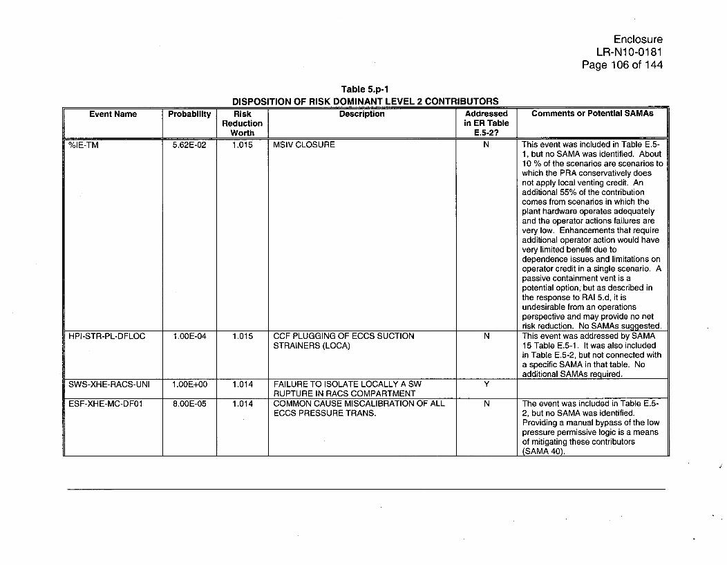
EnclosureLR-N10-0181
Page 106 of 144
Table 5.p-1DISPOSITION OF RISK DOMINANT LEVEL 2 CONTRIBUTORS
Event Name Probability Risk Description Addressed Comments or Potential SAMAsReduction in ER Table
Worth E.5-2?%IE-TM 5.62E-02 1.015 MSIV CLOSURE N This event was included in Table E.5-
1, but no SAMA was identified. About10 % of the scenarios are scenarios towhich the PRA conservatively doesnot apply local venting credit. Anadditional 55% of the contributioncomes from scenarios in which theplant hardware operates adequatelyand the operator actions failures arevery low. Enhancements that requireadditional operator action would havevery limited benefit due todependence issues and limitations onoperator credit in a single scenario. Apassive containment vent is apotential option, but as described inthe response to RAI 5.d, it isundesirable from an operationsperspective and may provide no netrisk reduction. No SAMAs suggested.
HPI-STR-PL-DFLOC 1.OOE-04 1.015 CCF PLUGGING OF ECCS SUCTION N This event was addressed by SAMASTRAINERS (LOCA) 15 Table E.5-1. It was also included
in Table E.5-2, but not connected witha specific SAMA in that table. Noadditional SAMAs required.
SWS-XHE-RACS-UNI 1.00E+00 1.014 FAILURE TO ISOLATE LOCALLY A SW YRUPTURE IN RACS COMPARTMENT
ESF-XHE-MC-DF01 8.OOE-05 1.014 COMMON CAUSE MISCALIBRATION OF ALL N The event was included in Table E.5-ECCS PRESSURE TRANS. 2, but no SAMA was identified.
Providing a manual bypass of the lowpressure permissive logic is a meansof mitigating these contributors(SAMA 40).

EnclosureLR-N10-0181
Page 107 of 144
Table 5.p-1
DISPOSITION OF RISK DOMINANT LEVEL 2 CONTRIBUTORS
Event Name Probability Risk Description Addressed Comments or Potential SAMAsReduction in ER Table
Worth E.5-2?
XHOS-RIVER-LT70 6.90E-01 1.013 RIVER TEMPERATURE IS LESS THAN 70 F N This event was included in Table E.5-1, but no SAMA was identified. Over40% of the scenarios conservativelydo not credit local venting for longheat removal. If this proceduralizedaction is credited, these cases are nolonger significant contributors. About12% are directly addressed by SAMA4. An additional 13% are LOOPevents addressed by SAMA 5. Noadditional SAMAs suggested.
%FLFPS-CR 1.10E-05 1.013 FPS RUPTURE OUTSIDE CONTROL ROOM YFPS-XHE-CRISOL 1.00E+00 1.013 Operator fails to secure FPS given CR area Y
ruptureMCR-PHE-DOOR 5.OOE-01 1.013 MCR DOOR FAILS DUE TO WATER Y
PRESSURERHS-MDP-TM-PB 1.58E-02 1.013 RHS PUMP TRAIN B IN TEST AND MAINT YLPI-XHE-AT-LVL 4.00E-02 1.013 FAILURE TO CONTROL LP ECCS TO N The event was included in Table E.5-
PREVENT OVERFILL 2, but no SAMA was identified. About60% of the contributors including thisevent include failure to bypass the lowlevel MSIV isolation logic. This isaddressed the response to RAI 5.j bySAMA RAI5j-IE1. No additionalSAMAs required.

EnclosureLR-N10-0181
Page 108 of 144
Table 5.p-1DISPOSITION OF RISK DOMINANT LEVEL 2 CONTRIBUTORS
Event Name Probability Risk Description Addressed Comments or Potential SAMAsReduction in ER Table
__Worth E.5-2?
DCP-XHE-PORTA 6.20E-02 1.013 FAILURE TO CROSS TIE BUS TO BATTERY N This event was addressed by SAMA 5CHARGER PORTABLE SUPPLY in Table E.5-1, which could have
some impact, but would be limited bydependence issues. Over 40% of thecontributors include failure of theSACS HX bypass valves or thetemperature controllers that governthe valves. If the PRA model includedcredit for the existing procedures andtraining address these failures, theywould no longer be significantcontributors. An additional 15% of thecontribution is addressed by SAMAs17 and 18 (or in the response to RAI7.a). No additional SAMAs required.
XHOS-STBY-DP502LT 5.00E-01 1.012 PUMP SSW DP502 IN STANDBY WITH 2 N The event was included in Table E.5-PUMPS OPERATING 2, but no SAMA was identified.
Almost 60% of the scenariosconservatively do not credit localventing for long heat removal. If thisproceduralized action is credited,these cases are no longer significantcontributors. An additional 20% arerelated to combinations of power andcooling water failures that could bemitigated by SAMA 4. No additionalSAMAs required.
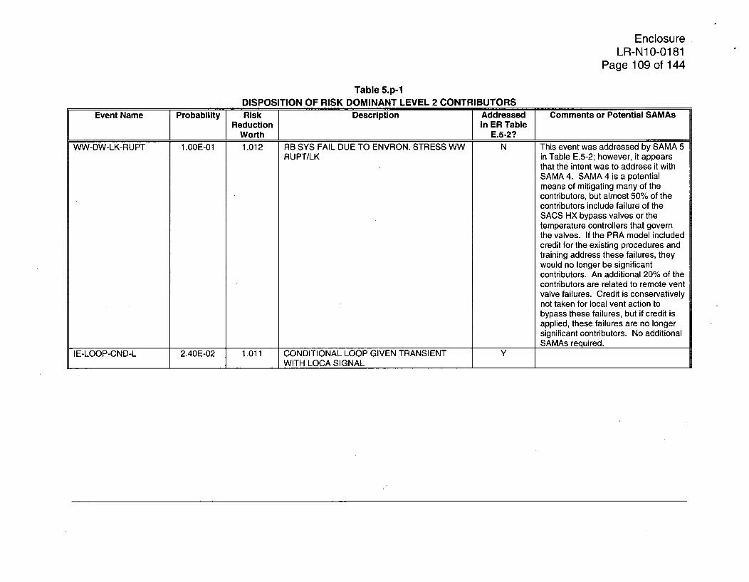
EnclosureLR-N1 0-0181
Page 109 of 144
Table 5.p-1DISPOSITION OF RISK DOMINANT LEVEL 2 CONTRIBUTORS
Event Name Probability Risk Description Addressed Comments or Potential SAMAsReduction in ER Table
Worth E.5-2?
WW-DW-LK-RUPT 1.OOE-01 1.012 RB SYS FAIL DUE TO ENVRON. STRESS WW N This event was addressed by SAMA 5RUPT/LK in Table E.5-2; however, it appears
that the intent was to address it withSAMA 4. SAMA 4 is a potentialmeans of mitigating many of thecontributors, but almost 50% of thecontributors include failure of theSACS HX bypass valves or thetemperature controllers that governthe valves. If the PRA model includedcredit for the existing procedures andtraining address these failures, theywould no longer be significantcontributors. An additional 20% of thecontributors are related to remote ventvalve failures. Credit is conservativelynot taken for local vent action tobypass these failures, but if credit isapplied, these failures are no longersignificant contributors. No additionalSAMAs required.
IE-LOOP-CND-L 2.40E-02 1.011 CONDITIONAL LOOP GIVEN TRANSIENT YWITH LOCA SIGNAL
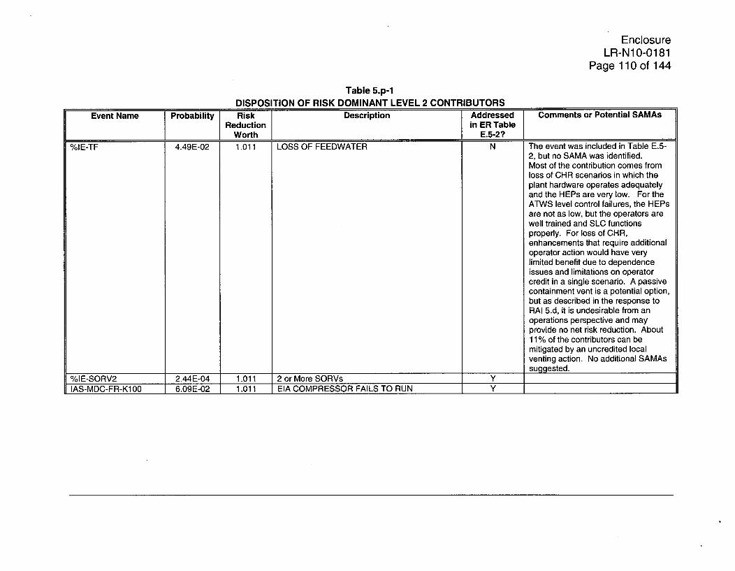
EnclosureLR-N10-0181
Page 110 of 144
Table 5.p-1DISPOSITION OF RISK DOMINANT LEVEL 2 CONTRIBUTORS
Event Name Probability Risk Description Addressed Comments or Potential SAMAsReduction in ER Table
Worth E.5-2?
%IE-TF 4.49E-02 1.011 LOSS OF FEEDWATER N The event was included in Table E.5-2, but no SAMA was identified.Most of the contribution comes fromloss of CHR scenarios in which theplant hardware operates adequatelyand the HEPs are very low. For theATWS level control failures, the HEPsare not as low, but the operators arewell trained and SLC functionsproperly. For loss of CHR,enhancements that require additionaloperator action would have verylimited benefit due to dependenceissues and limitations on operatorcredit in a single scenario. A passivecontainment vent is a potential option,but as described in the response toRAI 5.d, it is undesirable from anoperations perspective and mayprovide no net risk reduction. About11% of the contributors can bemitigated by an uncredited localventing action. No additional SAMAs
_________________ _________ _________ suggested.%IE-SORV2 2.44E-04 1.011 2 or More SORVs Y
IAS-MDC-FR-K100 6.09E-02 1.011 EIA COMPRESSOR FAILS TO RUN Y
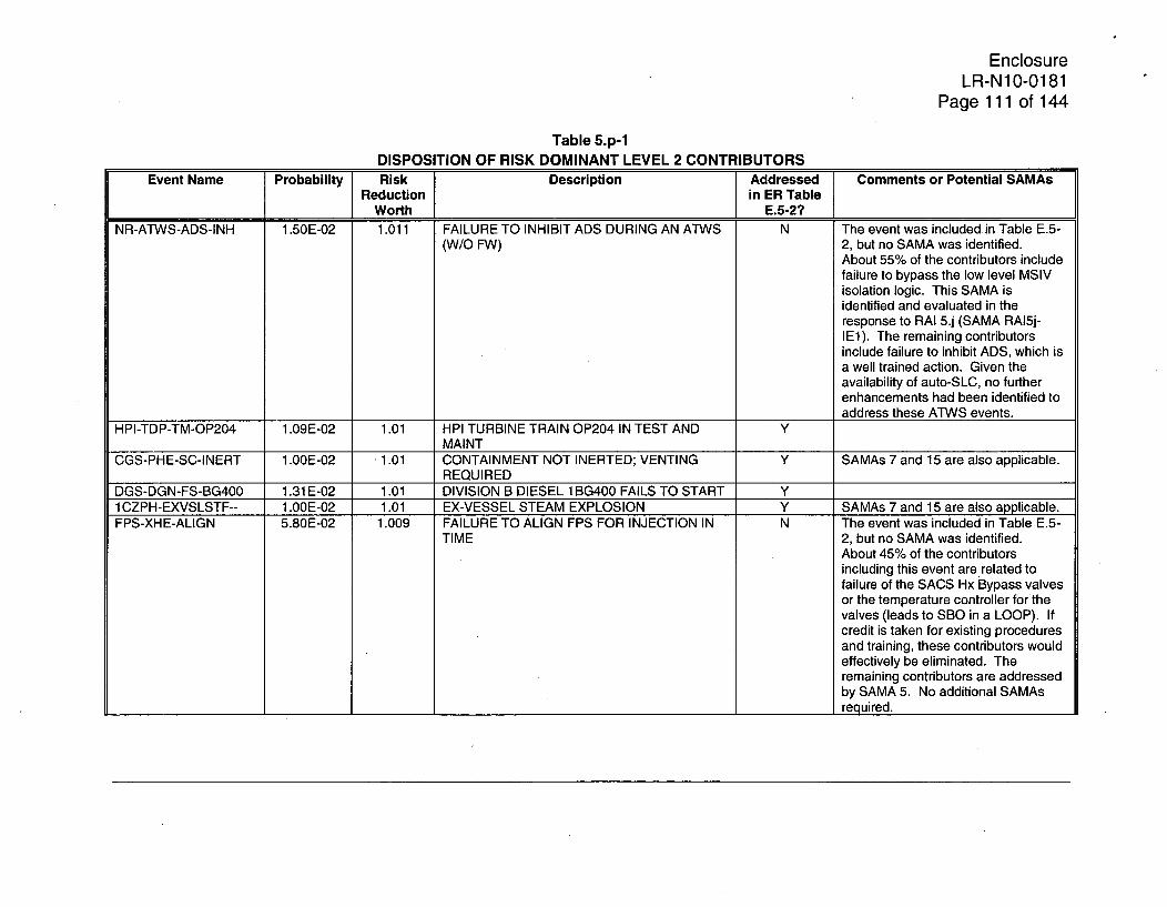
EnclosureLR-N1 0-0181
Page 111 of 144
Table 5.p-1DISPOSITION OF RISK DOMINANT LEVEL 2 CONTRIBUTORS
Event Name Probability Risk Description Addressed Comments or Potential SAMAsReduction in ER Table
Worth E.5-2?NR-ATWS-ADS-INH 1.50E-02 1.011 FAILURE TO INHIBIT ADS DURING AN ATWS N The event was included in Table E.5-
(W/O FW) 2, but no SAMA was identified.About 55% of the contributors includefailure to bypass the low level MSIVisolation logic. This SAMA isidentified and evaluated in theresponse to RAI 5.j (SAMA RAI5j-IE1). The remaining contributorsinclude failure to inhibit ADS, which isa well trained action. Given theavailability of auto-SLC, no furtherenhancements had been identified toaddress these ATWS events.
HPI-TDP-TM-OP204 1.09E-02 1.01 HPI TURBINE TRAIN OP204 IN TEST AND YMAINT
CGS-PHE-SC-INERT 1.00E-02 1.01 CONTAINMENT NOT INERTED; VENTING Y SAMAs 7 and 15 are also applicable.REQUIRED
DGS-DGN-FS-BG400 1.31 E-02 1.01 DIVISION B DIESEL 1BG400 FAILS TO START Y1 CZPH-EXVSLSTF-- 1.OOE-02 1.01 EX-VESSEL STEAM EXPLOSION Y SAMAs 7 and 15 are also applicable.FPS-XHE-ALIGN 5.80E-02 1.009 FAILURE TO ALIGN FPS FOR INJECTION IN N The event was included in Table E.5-
TIME 2, but no SAMA was identified.About 45% of the contributorsincluding this event are related tofailure of the SACS Hx Bypass valvesor the temperature controller for thevalves (leads to SBO in a LOOP). Ifcredit is taken for existing proceduresand training, these contributors wouldeffectively be eliminated. Theremaining contributors are addressedby SAMA 5. No additional SAMAsrequired.

EnclosureLR-N10-0181
Page 112 of 144
Table 5.p-1DISPOSITION'OF RISK DOMINANT LEVEL 2 CONTRIBUTORS
Event Name Probability Risk Description Addressed Comments or Potential SAMAsReduction in ER Table
Worth E.5-2?
LPI-XHE-AT-LVLF 1.OOE-01 1.009 FAILURE TO CNTRL LP ECCS TO PRVNT N The event was included in Table E.5-OVERFILL GIVEN HPI FAILS 2, but no SAMA was identified. Over
60% of the contributors include failureto bypass the low level MSIV isolationlogic. This SAMA is identified andevaluated in the response to RAI 5.j(SAMA RAI5j-IE1). The remainingcontributors include early level controlfailure, which is a well trained action.Given the availability of auto-SLC, nofurther enhancements had beenidentified to address these ATWSevents.
NRHVCSWGR24-01 4.10E-03 1.009 Fail to restore SWGR room cooling YSLC-TNK-LO-10204 7.55E-03 1.008 SLC STORAGE TANK CONCENTRATION OUT N The event was included in Table E.5-
OF SPEC. 2, but no SAMA was identified. Anindependent liquid boron injectionsystem that is tested and maintainedseparately could be installed toaddress these types of failures (SAMARAI5p-1).
%FLTORUS 2.80E-06 1.008 TORUS RUPTURE IN TORUS ROOM N The event was included in Table E.5-2and SAMA 1 was identified as apotentially relevant enhancement;however, SAMA 1 would have only asmall impact on .these contributors.Refer to the response to RAI 5.a for adisposition of this event.
DGS-DGN-FS-AG400 1.31 E-02 1.008 DIVISION A DIESEL 1AG400 FAILS TO START YOSPR30MIN-GR 8.25E-01 1.008 FAILURE TO RECOVER GRID LOOP W/IN 30 Y
MIN.RCI-MOV-LK-ROOM 1.OOE-01 1.008 PROBABILITY OF STEAM LEAK INTO RCI
ROOM

EnclosureLR-N10-0181
Page 113 of 144
Table 5.p-1DISPOSITION OF RISK DOMINANT LEVEL 2 CONTRIBUTORS
Event Name Probability Risk Description Addressed Comments or Potential SAMAsReduction in ER Table
Worth E.5-2?SWS-STR-FR-DF01 2.78E-06 1.007 CCF FAILURE TO RUN ALL SWS STRNR Y The event was included in Table E.5-2
MOTORS and addressed with SAMA 5, whichcould provide some benefit. However,63% of the contribution is related toremote failures of valves HV-4964 orHV-11541. The PRA modelconservatively does not credit thelocal venting action to bypass thesefailures, but the action is applicable.An additional 15% of the contributorsconservatively do not credit localcontainment vent in long term SBOscenarios with portable generator anddiesel fire injection success, butagain, local venting is applicable. Noadditional SAMAs required.
HPI-XHE-AT-CS 1.10E-01 1.007 CREW BLOWS DOWN BEFORE LVL IS N The event was included in Table E.5-CONTROLLED BY HPCI (3600 GPM) 2, but no SAMA was identified.
About 60% of the contributors includefailure to bypass the low level MSIVisolation logic. This SAMA isidentified and evaluated in theresponse to RAI 5.j (SAMA RAI5j-
DGS-DGN-FS-DG400_ _ _ _ 1.31__ E_02_1.007_DIVISIONDDIESEL_1_DG400_FAILSTOSTART_ _jIE1). No additional SAMAs required.DGS-DGN-FS-DG400 1.31 E-02 1.007 DIVISION D DIESEL 1 DG400 FAILS TO START Y______________
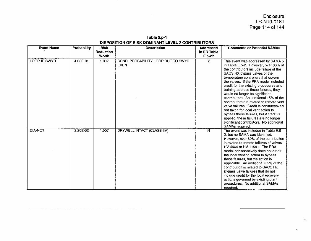
EnclosureLR-N10-0181
Page 114 of 144
Table 5.p-1DISPOSITION OF RISK DOMINANT LEVEL 2 CONTRIBUTORS
Event Name Probability Risk Description Addressed Comments or Potential SAMAsReduction in ER Table
Worth E.5-2?LOOP-IE-SWYD 4.03E-01 1.007 COND. PROBABILITY LOOP DUE TO SWYD Y This event was addressed by SAMA 5
EVENT in Table E.5-2. However, over 60% ofthe contributors include failure of theSACS HX bypass valves or thetemperature controllers that governthe valves. If the PRA model includedcredit for the existing procedures andtraining address these failures, theywould no longer be significantcontributors. An additional 15% of thecontributors are related to remote ventvalve failures. Credit is conservativelynot taken for local vent action tobypass these failures, but if credit isapplied, these failures are no longersignificant contributors. No additionalSAMAs required.
DIA-NOT 2.20E-02 1.007 DRYWELL INTACT (CLASS IIA) N The event was included in Table E.5-2, but no SAMA was identified.However, over 60% of the contributionis related to remote failures of valvesHV-4964 or HV-1 1541. The PRAmodel conservatively does not creditthe local venting action to bypassthese failures, but the action isapplicable. An additional 3.5% of thecontribution is related to SACC HxBypass valve failures that do notinclude credit for the local recoveryactions governed by existing plantprocedures. No additional SAMAsrequired.

EnclosureLR-N10-0181
Page 115 of 144
Table 5.p-1DISPOSITION OF RISK DOMINANT LEVEL 2 CONTRIBUTORS
Event Name Probability Risk Description Addressed Comments or Potential SAMAsReduction in ER Table
Worth E.5-2?WWA 1.OOE+00 1.007 WETWELL AIRSPACE FAILURES (CLASS IIA) N The event was included in Table E.5-2
and addressed by SAMA 4. SAMA 4may provide some benefit; however,over 60% of the contribution is relatedto remote failures of valves HV-4964or HV-1 1541. The PRA modelconservatively does not credit thelocal venting action to bypass thesefailures, but the action is applicable.An additional 3.5% of the contributionis related to SACC Hx Bypass valvefailures that do not include credit forthe local recovery actions governedby existing plant procedures. Noadditional SAMAs required.
SAC-MDP-TM-SSWB 2.30E-05 1.006 SAC A IN MAINT. COINCIDENT WITH SSW B N The event was included in Table E.5-2, but it is addressed with SAMA 3,which does not mitigate the high-moderate contributors. About 65% ofthe contributors containing the eventare binned to core damage withoutcrediting local containment venting. Ifthis action is credited, these scenariosare no longer important contributors.Given that the gas turbine does notshare the SACS cooling waterdependencies with the EDG, SAMA 5would address many of the remainingscenarios. No additional SAMAsrequired.

EnclosureLR-N10-0181
Page 116 of 144
Table 5.p-1DISPOSITION OF RISK DOMINANT LEVEL 2 CONTRIBUTORS
Event Name Probability Risk Description Addressed Comments or Potential SAMAsReduction in ER Table
Worth E.5-2?NR-UV-WTLVL-20M 2.1OE-02 1.006 FAILURE TO CONTROL RPV WATER LVL Y The event was included in Table E.5-
W/HIGH PRESS. INJ. SYS. 2, but it is addressed with SAMA 1 viaTable E.5-1. Given that 100% of thecontributors include portablegenerator hardware failure, it isassumed that SAMA 5 was intendedto address this event. No additionalSAMAs required.
%IE-MLRHR 1.44E-05 1.006 Medium LOCA - RHR N Over 75% of the contributors includefailure to manually depressurize theRPV. SAMA 1 is applicable.
DGS-DGN-FS-DF01 1.03E-05 1.006 CCF FAILURE TO START OF SDG'S A -B -C - N Over 65% of the contributorsAND D containing this event are binned to
core damage without crediting localcontainment venting. If this action iscredited, these scenarios are nolonger important contributors. Anadditional 15% include successfuloperator alignment of the portablegenerator with generator hardwarefailure or injection alignment failures,which could be addressed by SAMA5. No additional SAMAs required.
CAC-AOV-VF-1 1541 1.20E-04 1.006 HV-1 1541 FAILS DUE TO HARSH N About 30% of the contributors includeENVIRONMENT Service Water Pump Room cooling
failures. These can be addressed bySAMAs 17 and 18. Also,proceduralizing the use of alternateroom cooling is a potential solution(refer to the response to RAI 7.a foradditional information).

EnclosureLR-N10-0181
Page 117 of 144
Table 5.p-1DISPOSITION OF RISK DOMINANT LEVEL 2 CONTRIBUTORS
Event Name Probability Risk Description Addressed Comments or Potential SAMAsReduction in ER Table
I Worth E.5-2?CAC-AOV-VF-4964 1.20E704 - 1.006 HV-4964 FAILS-DUE TO HARSH N About 30% of thecontributors include
ENVIRONMENT Service Water Pump Room coolingfailures. These can be addressed bySAMAs 17 and 18. Also,proceduralizing the use of alternateroom cooling is a potential solution(refer to the response to RAI 7.a foradditional information).
%FLSWAB-RACS-U 7.60E-08 1.006 FREQ OF COMMON HEADER TO RACS N The event was included in Table E.5-RUPTURE (UNISOLABLE) 2, but no SAMA was identified.
These flooding scenarios can beaddressed by SAMA 7. No additionalSAMAs required.
DGS-DGN-TM-BG400 1.30E-02 1.006 DGS TRAIN BG400 IN TEST AND MAINT YNR-SOX-DEP-SRV 1.60E-03 1.005 FAILURE TO MAN. DEPRESS. FOR AN SORV N The scenarios including this failure
W/NO HIGH PRESS. INJ. can be mitigated by SAMA 1.TAF-S 9.13E-01 1.005 BREAK ABOVE TAF (BOC) N About 50% of the contribution
includes breaks in the steam tunnel.For these breaks, the reactor buildingis not significantly degraded and theECCS systems are potentiallyavailable, but have otherwise failed.Alternate injection is a viable meansof preventing core damage, but thePRA conservatively does not creditservice water injection through RHR.If SW injection were credited, thesescenarios would no longer besignificant contributors. No additionalSAMAs required.

EnclosureLR-N10-0181
Page 118 of 144
Table 5.p-1DISPOSITION OF RISK DOMINANT LEVEL 2 CONTRIBUTORS
Event Name Probability Risk Description Addressed Comments or Potential SAMAsReduction in ER Table
Worth E.5-2?SRV-TNK-LK-TRANS 1.00E-04 1.005 FAILURE OF 13/14 ACCUMULATORS N The event was included in Tables E.5-
(LEAKAGE) (NON-SBO) 1 and E.5-2, but no SAMA wasidentified. Almost all of thecontributing scenarios includeHPCI/RCIC success. Credit isconservatively no taken for thegradual cooldown that would occurand the ability to transition to RHR forlevel control and heat removal. If thiscontrol transition was credited, thesecontributors would be eliminated. Noadditional SAMAs required.
CAC-DSK-RUPTURE 1.OOE-04 1.005 RUPTURE DISK FAILS TO RUPTURE N About 30% of the contributors includeService Water Pump Room coolingfailures. These can be addressed bySAMAs 17 and 18. Also,proceduralizing the use of alternateroom cooling is a potential solution(refer to the response to RAI 7.a foradditional information).
CNT-SPE-LV-GT180 1.00E-04 1.005 TORUS WATER LEVEL GT 180 IN. N High water level in the Torus preventstorus venting while loss of SW fails airto the 6" hard pipe vent for heatremoval (65% of the contributors).These scenarios could be addressedby SAMA 3, but steps would likely betaken to address torus water level ifthe torus vent was needed. NoSAMAs required.
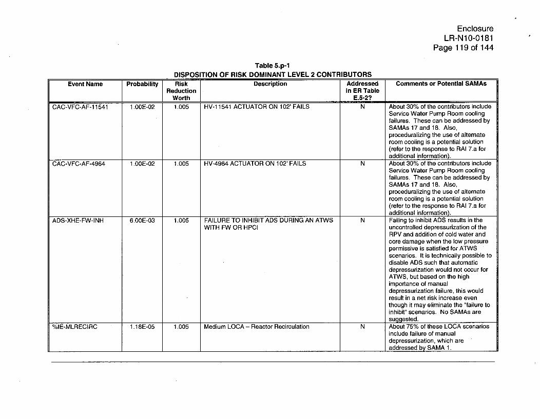
EnclosureLR-N10-0181
Page 119 of 144
Table 5.p-1DISPOSITION OF RISK DOMINANT LEVEL 2 CONTRIBUTORS
Event Name Probability Risk Description Addressed Comments or Potential SAMAsReduction in ER Table
Worth E.5-2?CAC-VFC-AF-1 1541 1.00E-02 1.005 HV-1 1541 ACTUATOR ON 102' FAILS N About 30% of the contributors include
Service Water Pump Room coolingfailures. These can be addressed bySAMAs 17 and 18. Also,proceduralizing the use of alternateroom cooling is a potential solution(refer to the response to RAI 7.a foradditional information).
CAC-VFC-AF-4964 1.00E-02 1.005 HV-4964 ACTUATOR ON 102' FAILS N About 30% of the contributors includeService Water Pump Room coolingfailures. These can be addressed bySAMAs 17 and 18. Also,proceduralizing the use of alternateroom cooling is a potential solution(refer to the response to RAI 7.a foradditional information).
ADS-XHE-FW-INH 6.OOE-03 1.005 FAILURE TO INHIBIT ADS DURING AN ATWS N Failing to inhibit ADS results in theWITH FW OR HPCI uncontrolled depressurization of the
RPV and addition of cold water andcore damage when the low pressurepermissive is satisfied for ATWSscenarios. It is technically possible todisable ADS such that automaticdepressurization would not occur forATWS, but based on the highimportance of manualdepressurization failure, this wouldresult in a net risk increase eventhough it may eliminate the "failure toinhibit" scenarios. No SAMAs aresuggested.
%IE-MLRECIRC 1.18E-05 1.005 Medium LOCA - Reactor Recirculation N About 75% of these LOCA scenariosinclude failure of manualdepressurization, which areaddressed by SAMA 1.

EnclosureLR-N1 0-0181
Page 120 of 144
Table 5.p-1DISPOSITION OF RISK DOMINANT LEVEL 2 CONTRIBUTORS
Event Name Probability Risk Description Addressed Comments or Potential SAMAsReduction in ER Table
Worth E.5-2?DCP-BDC-ST-DF01 3.87E-08 1.005 CCF FAILURE 125VDC BUSES 10D410 - 20 - N The event was included in Table E.5-
30 - & 40 2, but no SAMA was identified.HCGS has procedures to operateRCIC without AC or-DC power thatare not credited. While failure of theDC panels in the earliest time framesof an accident may preclude fullimplementation of the procedure, it isexpected that many of the scenarioscould be mitigated with local RCICoperation. No additional SAMAsrequired.
CRH-SPE-ARI-FAIL 5.00E-02 1.005 FAILURE OF THE AUTO ARI N About 30% of the contributors includefailure to bypass the low level MSIVisolation logic. This SAMA isidentified and evaluated in theresponse to RAI 5.j (SAMA RAI5j-IE1). About 50% of the contribution isrelated to failure to control level early.Given the availability of auto-SLC andthat the operators are well trained onATWS scenarios, no furtherenhancements had been identified toaddress these ATWS events.
RPPARPS-ELECFCC 3.70E-06 1.005 RPS ELECTRICAL FAILURE N About 30% of the contributors includefailure to bypass the low level MSIVisolation logic. This SAMA isidentified and evaluated in theresponse to RAI 5.j (SAMA RAI5j-IE1). About 50% of the contribution isrelated to failure to control level early.Given the availability of auto-SLC andthat the operators are well trained onATWS scenarios, no furtherenhancements had been identified toaddress these ATWS events.

EnclosureLR-N1 0-0181
Page 121 of 144
Table 5.p-1DISPOSITION OF RISK DOMINANT LEVEL 2 CONTRIBUTORS
Event Name Probability Risk Description Addressed Comments or Potential SAMAsReduction in ER Table
Worth E.5-2?VSW-FAN-FR-DF12 9.90E-06 1.005 CCF FAILURE FANS A THRU DVH401 FAIL TO Y
RUNCSS-STR-PL-A 8.36E-03 1.005 CSS PUMP A SUCTION STRAINERS Y
PLUGGED IN STANDBYCSS-STR-PL-B 8.36E-03 1.005 CSS PUMP B SUCTION STRAINERS Y
PLUGGED IN STANDBYCSS-STR-PL-C 8.36E-03 1.005 CSS PUMP C SUCTION STRAINERS Y
PLUGGED IN STANDBYCSS-STR-PL-D 8.36E-03 1.005 CSS PUMP D SUCTION STRAINERS Y
PLUGGED IN STANDBYIGS-XHE-FO-V5125 1.20E-01 1.005 OPERATOR FAILS TO OPEN XCONNECT N Almost all of the contributing
VALVE scenarios include HPCI/RCICsuccess. Credit is conservatively notaken for the gradual cooldown thatwould occur and the ability totransition to RHR for level control andheat removal. If this control transitionwas credited, these contributors wouldbe eliminated. No additional SAMAsrequired.
ACP-BAC-HV-RMCLG 9.OOE-01 1.005 FAILURE OF EQUIPMENT GIVEN NO SWG YROOM COOLING
OPI -IA-NOT 8.40E-01 1.005 RPV DEPRESSURIZATION SUCCESSFUL (IA) N The event was included in Table E.5-2, but no SAMA was identified.About 20% of the contributors arefloods initiated in the fire protectionsystem which can be addressed withSAMA 8. Over 70% of thecontributors include loss of all DCpower. HCGS has procedures tooperate RCIC without AC or DCpower, but they are not credited. Noadditional SAMAs are required.

EnclosureLR-N1 0-0181
Page 122 of 144
Table 5.p-1DISPOSITION OF RISK DOMINANT LEVEL 2 CONTRIBUTORS
Event Name Probability Risk Description Addressed Comments or Potential SAMAsReduction in ER Table
Worth E.5-2?IGS-LOCASIG 1.OOE+00 1.005 LOCA SIGNAL PRESENT WHEN PCIGS N Almost all of the contributing
NEEDED scenarios include HPCI/RCICsuccess. Credit is conservatively notaken for the gradual cooldown thatwould occur and the ability totransition to RHR for level control andheat removal. If this control transitionwas credited, these contributors wouldbe eliminated. No additional SAMAsrequired.

EnclosureLR-N1 0-0181
Page 123 of 144
Table 5.p-2RESULTS BY RELEASE CATEGORY
Release Category ST1 ST2 ST3 ST4 ST5 ST6 ST7 ST8 ST9 ST1 0 ST1 1 TotalFrequencyBASE 1.83E-07 7.15E-08 1.30E-07 9.70E-07 8.34E-08 3.48E-07 2.16E-07 0.OOE+00 2.68E-07 2.39E-07 1.93E-06 4.44E-06FrequencysAMA 1.68E-07 7.15E-08 1.30E-07 9.70E-07 8.34E-08 3.35E-07 2.16E-07 0.OOE+00 2.68E-07 2.39E-07 1.93E-06 4.41E-06Dose-RiSkBASE 3.33 0.99 3.05 8.49 0.92 4.55 1.37 0.00 0.00 0.16 0.00 22.86Dose-RiSkSAMA 3.06 0.99 3.04 8.49 0.92 4.39 1.37 0.00 0.00 0.16 0.00 22.42OECRBASE $21,045 $6,888 $14,975 $62,159 $7,694 $31,881 $10,235 $0 $0 $177 $0 $155,055OECRSAMA $19,320 $6,885 $14,950 $62,177 $7,698 $30,720 $10,217 $0 $0 $177 $0 $152,144

EnclosureLR-N10-0181
Page 124 of 144
5.q Section E.5.1.3.7 identifies SAMA 11 as having been identified from the review ofselected industry analyses. However this SAMA is not included in the list ofPhase 1 SAMAs (Table E.5-3) and it was not evaluated in the environmentalreport (ER). Furthermore, the disposition of James A. Fitzpatrick Nuclear PowerPlant SAMA 62 in Section E.5.1.3.3 states that a SAMA to develop a procedureto open the door of [emergency diesel generator (EDG)] buildings upon hightemperature alarm (i.e., HCGS SAMA 11) was not included due to the smallcontribution to HCGS risk. Clarify this discrepancy and provide an evaluation ofSAMA 11, if applicable.
PSEG Response:
EDG room cooling is not a significant contributor to the HCGS risk profile, asidentified in the disposition of James A. Fitzpatrick Nuclear Power Plant SAMA62 in Section E.5.1.3.3 of the HCGS ER.
For HCGS, each EDG is supported by redundant room cooling trains; scenariosincluding fan or flow-path failures of both trains fall below the truncation limits forthe Level 1 and Level 2 PRA models. Further, the Safety Auxiliaries CoolingSystem (SACS) supports EDG Building room cooling and EDG jacket watercooling. Consequently, a loss of SACS cannot be mitigated by opening the EDGBuilding doors because the EDGs would still fail due to lack of jacket watercooling. For these reasons, a procedure change to direct the operators to openthe EDG Building doors on loss of room cooling is not required for HCGS.
HCGS SAMA "11" (Industry 1) should not be included in summary sectionE.5.1.3.7 of the ER. Section E.5.1.3 was developed in stages, including one thatimplemented a preliminary SAMA numbering format. While the preliminary draftof Section E.5.1.3.7 originally identified SAMA I1 as a potential SAMA forinclusion on the HCGS list, it was ruled out after a review of the HCGSconfiguration and PRA results.
5.r PSEG's review of the Duane Arnold Energy Center (Duane Arnold) SAMAs inSection E.5.1.3.5 did not address Duane Arnold SAMA 117, "increase boronconcentration or enrichment in the standby liquid control SLC system," which wasdetermined to be potentially cost-beneficial in the uncertainty analysis. Reviewthis SAMA for applicability to HCGS and provide an evaluation of this SAMA, ifapplicable.
PSEG Response:
Increasing the boron concentration of the SLC system, as proposed in DAECSAMA 117, is intended to increase the length of time that is available for theoperator to initiate SLC injection in an ATWS scenario. The SLC system atHCGS is automatically initiated and the proposed SAMA would have a negligiblebenefit for the plant. Scenarios including the manual SLC initiation action fallbelow the truncation limit for both the Level 1 and Level 2 HCGS PRA models.

EnclosureLR-N1 0-0181
Page 125 of 144
6. Provide the following with regard to the Phase 2 cost-benefit evaluations:
6.a Section E.6 states that plant personnel developed HCGS-specific implementationcost estimates for each of the SAMAs. Provide a description of: the processPSEG used to develop the SAMA implementation costs, the level of detail usedto develop the cost estimates (e.g., general cost categories such as hardwaredesign, procurement, installation, and testing, procedure development, qualityassurance and licensing support, etc.), and how the calculations aredocumented. Specifically discuss whether the cost estimates includereplacement power costs during outages required to implement themodifications, contingency costs for unforeseen difficulties, and inflation.
PSEG Response:
Following initial development of the SAMAs, a series of meetings were heldbetween the personnel responsible for the SAMA development and the twoPSEG License Renewal Site Leads. The Site Leads are Engineering Managersand each have over 25 years of plant experience including over 10 years withPSEG Nuclear. This experience includes project management, operations, plantengineering, design engineering, procedure support, simulators, and training.The purpose of the meetings was to validate each SAMA against plantconfiguration and to develop an estimate of its implementation cost. In someinstances, the Site Leads provided information that was used to refine the SAMAor to develop an alternate approach to reach the same objective at a lowerimplementation cost. At the conclusion of the series of meetings, the SAMAswere provided to the Design Engineering Manager for review and comment fromboth technical and cost perspectives. The SAMA information in the LRA reflectsthe final product of this process.
As shown in the following table, there are seven general cost categories. Costsare budgetary estimates, not detailed estimates. The cost estimates do notinclude contingencies or inflation. In addition to the cost information, the tableprovides a summary of the SAMA changes. This table was prepared for eachSAMA during the previously described series of meetings.
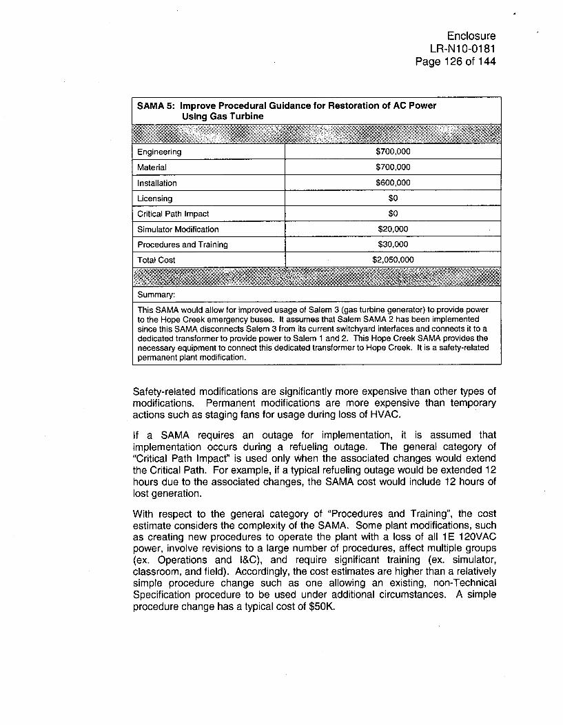
EnclosureLR-N1 0-0181
Page 126 of 144
SAMA 5: Improve Procedural Guidance for Restoration of AC PowerUsing Gas Turbine
Engineering $7,000
Material $7,000
Installation $600,000
Licensing $0
Critical Path Impact $0
Simulator Modification $20,000
Procedures and Training $30,000
Total Cost $2,050,000
Summary:
This SAMA would allow for improved usage of Salem 3 (gas turbine generator) to provide powerto the Hope Creek emergency buses. It assumes that Salem SAMA 2 has been implementedsince this SAMA disconnects Salem 3 from its current switchyard interfaces and connects it to adedicated transformer to provide power to Salem 1 and 2. This Hope Creek SAMA provides thenecessary equipment to connect this dedicated transformer to Hope Creek. It is a safety-relatedpermanent plant modification.
Safety-related modifications are significantly more expensive than other types ofmodifications. Permanent modifications are more expensive than temporaryactions such as staging fans for usage during loss of HVAC.
If a SAMA requires an outage for implementation, it is assumed thatimplementation occurs during a refueling outage. The general category of"Critical Path Impact' is used only when the associated changes would extendthe Critical Path. For example, if a typical refueling outage would be extended 12hours due to the associated changes, the SAMA cost would include 12 hours oflost generation.
With respect to the general category of "Procedures and Training", the costestimate considers the complexity of the SAMA. Some plant modifications, suchas creating new procedures to operate the plant with a loss of all 1 E 120VACpower, involve revisions to a large number of procedures, affect multiple groups(ex. Operations and I&C), and require significant training (ex. simulator,classroom, and field). Accordingly, the cost estimates are higher than a relativelysimple procedure change such as one allowing an existing, non-TechnicalSpecification procedure to be used under additional circumstances. A simpleprocedure change has a typical cost of $50K.
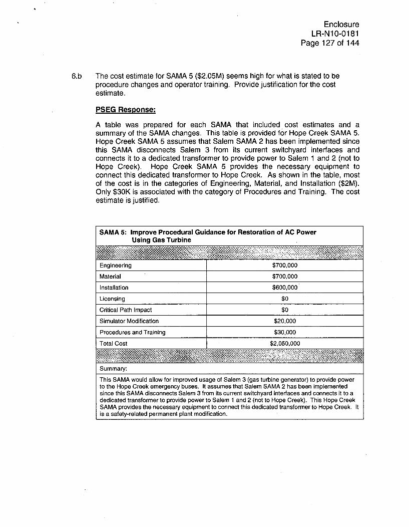
EnclosureLR-N10-0181
Page 127 of 144
6.b The cost estimate for SAMA 5 ($2.05M) seems high for what is stated to beprocedure changes and operator training. Provide justification for the costestimate.
PSEG Response:
A table was prepared for each SAMA that included cost estimates and asummary of the SAMA changes. This table is provided for Hope Creek SAMA 5.Hope Creek SAMA 5 assumes that Salem SAMA 2 has been implemented sincethis SAMA disconnects Salem 3 from its current switchyard interfaces andconnects it to a dedicated transformer to provide power to Salem 1 and 2 (not toHope Creek). Hope Creek SAMA 5 provides the necessary equipment toconnect this dedicated transformer to Hope Creek. As shown in the table, mostof the cost is in the categories of Engineering, Material, and Installation ($2M).Only $30K is associated with the category of Procedures and Training. The costestimate is justified.
SAMA 5: Improve Procedural Guidance for Restoration of AC PowerUsing Gas Turbine
Engineering $700,000
Material $700,000
Installation $600,000
Licensing $0
Critical Path Impact $0
Simulator Modification $20,000
Procedures and Training $30,000
Total Cost $2,050,000
Summary:
This SAMA would allow for improved usage of Salem 3 (gas turbine generator) to provide powerto the Hope Creek emergency buses. It assumes that Salem SAMA 2 has been implementedsince this SAMA disconnects Salem 3 from its current switchyard interfaces and connects it to adedicated transformer to provide power to Salem 1 and 2 (not to Hope Creek). This Hope CreekSAMA provides the necessary equipment to connect this dedicated transformer to Hope Creek. Itis a safety-related permanent plant modification.

EnclosureLR-N10-0181
Page 128 of 144
6.c In Section E.6.4, the benefit of utilizing the gas-turbine generator (SAMA 5) wasassessed by reducing the probability of failure to cross-tie the HCGS EDGS.This assumption does not provide credit for the gas turbine in the situation whereall the emergency generators are unavailable. Discuss the impact of thisomission.
PSEG Response:
Per Section E.6.4, reducing the operator action for cross tie of the EDGs from0.99 to 0.1 reduces the Level 1 CDF from 4.44E-6/yr to 4.10E-6/yr (i.e., a 7.7%decrease). It is understood that modeling cross tie of the HCGS EDGs as asurrogate for utilizing the Salem gas turbine generator (GTG) to supply HCGSdoes not credit the GTG in situations where all of the EDGs are unavailable.However, using the EDG cross tie as a surrogate overestimates the benefit of theGTG for the following reasons:
* Cross tie of the EDGs is credited for all types of LOOP scenarios (i.e., plantcentered, switchyard related, grid related, and weather related). In addition,for the purposes of SAMA 5, the EDG crosstie is assumed to be aligned andcredited at time=0.
* In the HC108B PRA, the GTG is only credited under certain types of LOOPscenarios. For example, the GTG is only credited for the portion of LOOPevents that are grid related. The GTG is not credited for weather relatedLOOP events because the weather is assumed to preclude the ability tosuccessfully perform cross tie operator actions in the switchyard. The GTG isalso not credited for plant centered and switchyard related LOOP eventsbecause the GTG needs to be aligned through the HCGS switchyard to theHCGS AC distribution system.
* Based on the HCGS Human Reliability Analysis (HRA), the GTG can bealigned within approximately 2 hours. Therefore, the GTG is not credited forLOOP scenarios with core damage in less than 2 hours. In the HC108B PRA,the GTG is only credited for LOOP scenarios where core damage is greaterthan 4 hours (i.e., non-LERF scenarios).
A sensitivity study was performed using the HC108B model to assume that theGTG was always available and reliable (i.e., failure probability, maintenanceunavailability, and human error probability set to 0.0). Given the constraints forcrediting the GTG as identified above, the sensitivity study showed that the Level1 CDF decreased from 4.44E-6/yr to 4.41 E-6/yr (i.e., <1% decrease).
Using the EDG crosstie as a surrogate evaluation for the GTG wouldoverestimate the benefit of the GTG. Not crediting the GTG in situations whereall of the EDGs are unavailable does not change the conclusions of SAMA 5.

EnclosureLR-N1 0-0181
Page 129 of 144
6.d The implementation cost for SAMA 10 ($1 00K) was based on the estimated costof a procedure change. However, the plant modification for SAMA 10 isdescribed as including the addition of a new pump. Provide justification for thecost estimate.
PSEG Response:
The particular wording used in Section E.6.7 of the SAMA report, "adding a newpump," was misinterpreted as the purchase of a pump that does not currentlyexist. However, use of the existing B.5.b security pump, which is included in thetitle description for this SAMA, should be interpreted as making an existing pumpavailable for use that was not previously credited by procedures such that theability to use a pump not previously available to the operator was considered a"new" pump. Therefore, the cost of this SAMA is based on upon procedurerevisions and operator training; purchase of new hardware or equipment was notconsidered necessary.
6.e SAMA 16, which involves replacing one of the four Switchgear Room coolingfans with a fan having a different design, was estimated to cost $400K. Providejustification for the cost estimate. In addition, the description of this SAMA notesthat an alternate means of cooling could involve use of multiple portable fans.Clarify whether this is a potentially lower cost alternative to SAMA 16 and, if so,provide an evaluation of a SAMA using multiple portable fans.
PSEG Response:
A table was prepared for each SAMA that included cost estimates and asummary of the SAMA changes. The following table provides the costbreakdown for SAMA 16.
SAMA 16: Use of Different Designs for Switchgear Room Cooling Fans
Engineering $150,000
Material $100,000Installation $100,000
Licensing $0Critical Path Impact $0
Simulator Modification $0Procedures and Training $50,000
Total Cost $400,000
Summary:
This SAMA considers replacing one of the switchgear room cooling fans with a different design soas to eliminate common cause failure of all fans.

EnclosureLR-N10-0181
Page 130 of 144
The use of portable fans and recovery of switchgear room cooling is alreadycredited within the PRA model via the HEP event NRHVCSWGR24-01. Thisevent appears in Table E.5-1 of the ER and was considered to be addressed bySAMA 16. That is, the failure of operators to stage portable fans is alreadyidentified in those same cutsets that involve common-cause failure of allswitchgear room cooling fans. Hence, the installation of a fan of a differentdesign was considered as one means of avoiding common-cause failure of allfans.
6.f SAMA 31 is similar to Salem SAMAs 21 and 22 in that each involves installing firebarriers to prevent the propagation of a fire between cabinets. HCGS SAMA 31has an estimated cost of $1.2M (one cabinet) compared to $3.23M (48 cabinets)and $1.6M (three cabinets) for Salem SAMAs 21 and 22, respectively. Clarifywhy the cost of installing fire barriers in one cabinet (HCGS SAMA 31) is only 25percent less than the cost for three cabinets (Salem SAMA 22) and only half thecost of 48 cabinets (Salem SAMA 21).
PSEG Response:
A table was prepared for each SAMA that included cost estimates and asummary of the SAMA changes. This table is provided for Hope Creek SAMA31. Although Salem SAMA 21 involves more cabinets, it is significantly simplerthan Salem SAMA 22 due to the location and structure of the cabinets in theRelay Room. Similar to Salem SAMA 22, Hope Creek SAMA 31 is morecomplicated than Salem SAMA 21 because it involves the Control Roomconsoles. Engineering costs are the same for Hope Creek SAMA 31 and SalemSAMA 22 ($800K). The material and installation costs per console are also thesame ($200K). The difference in total cost is due to the fact that the Engineeringcost at Salem is shared between two units and that there are three affectedconsoles in each Salem unit and only one affected console at Hope Creek. Thedifferences in the cost estimates are justified.

EnclosureLR-N110-0181
Page 131 of 144
SAMA 31: Improve Fire Barrier Protecting Control Console with MSIV Controls
Engineering $800,000
Material $200,000
Installation $200,000
Licensing $0
Critical Path Impact $0
Simulator Modification $0
Procedures and Training '$0
Total Cost $1,200,000
Summary:
This SAMA involves improving the capability of the MSIV console in the Control Room to containa fire (i.e. fire barrier) and thus stop propagation of the fire to adjacent consoles. This console hastight internal clearances and many openings for instrumentation. In addition to adding fire barriermaterials, the console has significant heat loads so ventilation modifications will be needed. TheEngineering costs include $100K for a feasibility study. This SAMA involves permanent plantmodifications.
6.g In Section E.6.17, it is stated that SAMA 35 was conservatively assumed toeliminate 99 percent of the risk associated with basic event %IE-FIRE38.However, the estimated total averted cost-risk is calculated using a reduction ofonly 90 percent. Clarify this discrepancy.
PSEG Response:
The method used to-calculate the averted cost-risk of SAMA 35 in the ER wastied to changes in the HCGS CDF rather than through a direct calculation usingthe fire scenario potential averted cost-risk values (PACR). A more accuratemethod of calculating the averted cost-risk is to multiply the %IE-FIRE38 PACRby 0.99 to obtain the averted cost-risk. Based on the PACRs provided in the ER,this would be $410,746:
Averted Cost-Risk = $414,895 * 0.99 = $410,746
If the averted cost-risk is recalculated using the fire PACRs from the response toRAI 5.j, the result is similar:
Averted Cost-Risk = $412,626 * 0.99 = $408,500
The conclusion that SAMA 35 is cost beneficial is not impacted as both of theabove averted cost-risk values are larger than the $370,000 estimate that wasused in the ER.

EnclosureLR-N10-0181
.Page 132 of 144
6.h The cost estimate for SAMA 36 ($270K) seems high for what appears to be a
procedure change. Provide justification for the cost estimate.
PSEG Response:
A table was prepared for each SAMA that included cost estimates and asummary of the SAMA changes. This table is provided for SAMA 36. ThisSAMA involves the creation of a group of procedures; not the revision of existingprocedures or creation of a single procedure. Currently, procedures identify themajor equipment that is impacted on the loss of individual buses but there is nointegrated procedural guidance for loss of all buses. It would be a significanteffort to determine a success path, to update the Simulator to include allnecessary components to implement the success path, to test the success path,and then to implement the new procedures. It is possible that the preferredsuccess path could involve permanent plant modifications. For the currentestimate, it is assumed that there are no permanent plant modifications. Thecost estimate is justified.
SAMA 36: Provide Procedural Guidance for Loss of All 1 E 120VAC Power
Engineering $0
Material $0
Installation $0
Licensing $0
Critical Path Impact $0
Simulator Modification $70,000
Procedures and Training $200,000
Total Cost $270,000
Summary:
This SAMA involves the development of procedures to operate the plant after a loss of all class1 E 120VAC power. It involves the creation of a group of procedures; not the revision of existingprocedures or creation of a single procedure. Currently, procedures identify the major equipmentthat is impacted on the loss of individual buses but there is no integrated procedural guidance forloss of all buses. It would be a significant effort to determine a success path, to update theSimulator to include all necessary components to implement the success path, to test the successpath, and then to implement the new procedures. It is possible that the preferred success pathcould involve permanent plant modifications. For the current estimate, it is assumed that thereare no permanent plant modifications.

EnclosureLR-N10-0181
Page 133 of 1446.i Provide the assumptions and PRA modeling changes used to model SAMAs 39
and 40 in Sections E.6.20 and E.6-21.
PSEG Response:
SAMA 39: Defeat HPCI/RCIC Torus Back Pressure Trip
During certain postulated plant scenarios where HPCI or RCIC are the onlymeans of RPV injection and the main condenser and Torus Cooling areunavailable. Loss of suppression pool cooling would eventually lead to loss ofHPCI/RCIC due to a turbine back pressure trip (e.g., RCIC @ 25 psig, HPCI @140 psig, or pool temperature above HCTL). For these types of scenarios, itdesirable to defeat the trip to allow continued HPCI/RCIC injection into the RPV.
This SAMA involves adding an operator action to defeat the HPCI/RCIC backpressure trip. This involves changing procedures and providing a means fordefeating the trip (e.g., jumpers or keylocks).
Assumptions:
1. For the purposes of this SAMA, it is assumed that the procedures andtraining would change to allow use of this defeat.
2. The HPCI turbine back pressure trip is currently 140 psig. Bypass of theHPCI back pressure trip would not be required for any PRA modeledscenarios. This SAMA should only apply to bypass of the RCIC turbine backpressure trip.
3. HPCI and RCIC with suction from the Torus can run for 24 hours withoutTorus Cooling. The containment conditions would likely reach the HCTLwithin 24 hours, require RPV depressurization, and preclude continued HPCIand RCIC operation. For the purposes of this SAMA, HPCI and RCIC areassumed to continue operating for 24 hours.
4. This SAMA is credited for transient scenarios with loss of the maincondenser, loss of Torus Cooling, loss of CRD, and failure to depressurizethe RPV. This SAMA is not credited for LOCA scenarios because the RPVwould eventually depressurize and preclude HPCI/RCIC operation. ThisSAMA is not credited for SBO scenarios because HPCI/RCIC operationwould be limited by DC battery life.
5. A human error probability (HEP) of 1 E-1 was selected as a screening value to
model this SAMA.
PRA Model Changes to Model SAMA 39:
The operator action to defeat the HPCI/RCIC back pressure permissive (HPI-XHE-FO-DFT-BP =1.OE-2) was added under the AND gate GTR-026_F. Thisgate models the following scenario for the loss of RPV makeup at high RPVpressure:

EnclosureLR-N10-0181
Page 134 of 144
* General Transient Initiating Events
" Feedwater or Power Conversion Systems Fail
" RHR In SPC Mode Fails Early
" HPCI or RCIC are initially available for high pressure injection, but areassumed unavailable long term (e.g., to support the 24 hour mission time)due to reaching the HCTL or the HPCI/RCIC turbine back pressure trip
* Enhanced CRD Unavailable
" Rx Depress Fails When Needed (Gen Trans)
The model was requantified with this change. The change to this specificaccident sequence represents the full impact of the addition of this recoveryaction. No other basic events or fault tree structures were affected.
As identified in Section E.6.20 of the HCGS Environmental Report, the modelchange resulted in decreasing the CDF from the base value of 4.44E-6/yr to4.01 E-6/yr (i.e., a decrease of 9.8%).
SAMA 40: Defeat RPV Low Pressure Permissive
This SAMA increases the reliability of the low pressure ECCS RPV low pressurepermissive circuitry. Given hardware failure or miscalibration of the low pressurepermissive circuitry, this SAMA evaluates the benefit of installing a manualbypass of the low pressure permissive logic. I
The ability of LPCI/CS to inject requires that the RPV be at low pressure. TheLow Pressure Permissive instrumentation is utilized to sense the pressure atwhich these low pressure systems may inject into the RPV. The malfunction ofthis instrumentation could prevent injection even when RPV pressure is at theallowed set point. The PRA includes the possibility of the common causemiscalibration of multiple low RPV pressure instruments (ESF-XHE-MC-DF01).
This SAMA involves installing a manual bypass of the low pressure permissivelogic. This will allow low pressure systems to inject when the failure is due to afalse pressure instrumentation or logic (ESF-XHE-MC-DF01). This changerequires procedure and operator training to realize the benefit of this SAMA.
Assumptions:
1. For the purposes of this SAMA, it was assumed that this system would requiremanual operation from the control room.
2. Failure of the both LPCI and CSS is due to common cause failure ormiscalibration of the RPV Low Pressure Permissive instrumentation.

EnclosureLR-N10-0181
Page 135 of 144
3. A HRA failure probability of 1 E-1 was selected as a screening value
PRA Model Changes to Model SAMA 40:
The probability for representative event "Common cause miscalibration of allECCS pressure transmitters" (ESF-XHE-MC-DF01) was changed from 8.OOE-05to 8.OOE-06. This change would simulate the common cause failure combinedwith the failure of the operator to bypass the permissive. No other basic eventsor fault tree structures were affected.
As identified in Section E.6.21 of the HCGS Environmental Report, the modelchange resulted in decreasing the CDF from the base value of 4.44E-6/yr to4.38E-6/yr (i.e., a decrease of 1.4%).

EnclosureLR-N1 0-0181
Page 136 of 144
6.j SAMA 40, which involves providing procedural guidance to bypass the reactorcore isolation cooling (RCIC) turbine exhaust pressure trip, was estimated to cost$620K. This cost is appreciably higher than the cost estimate of $250K forDuane Arnold SAMA 166. The Duane Arnold SAMA is also similar to, and thesource of the HCGS SAMA 40. Provide justification for the implementation costestimate for SAMA 40.
PSEG Response:
A table was prepared for each SAMA that included cost estimates and asummary of the SAMA changes. This table is provided for SAMA 40. ThisSAMA involves the installation of six key-lock switches to bypass various lowpressure permissives. Since it involves multiple permissives, the benefit can notbe obtained without installing key-lock switches due to the time required to installsix jumpers when compared to the time to operate six key-lock switches. Thecost estimate is justified.
SAMA 40: Install Manual Bypass of ECCS Low Pressure Permissive
Engineering $400,000
Material $50,000
Installation $100,000
Licensing $0
Critical Path Impact $0
Simulator Modification $20,000
Procedures and Training $50,000
Total Cost $620,000
Summary:
This SAMA involves the installation of six key-lock switches to bypass various low pressurepermissives. Since it involves multiple permissives, the benefit can not be obtained withoutinstalling key-lock switches due to the time required to install six jumpers when compared to thetime to operate six key-lock switches. This SAMA involves safety-related permanent plantmodifications.

0
EnclosureLR-N10-0181
Page 137 of 144
6.k SAMAs 33 and 34, which involve cross-tieing the 480V AC buses at HCGS, areeach estimated to cost $1.32M to. Wolf Creek SAMA 3 and Susquehanna SAMA2a, which also involve cross-tieing 4kV AC buses, are estimated to cost $328Kand $656K, respectively. Provide a more detailed description of both themodification and the implementation cost estimate for HCGS SAMAs 33 and 34.
PSEG Response:
A table was prepared for each SAMA that included cost estimates and asummary of the SAMA changes. These tables are provided for SAMAs 33 and34. Both SAMAs install new tie-breakers and cables for the associated 480VACbus cross-ties. Most of the cost for each SAMA is related to Engineering. TheEngineering costs are significant due to the electrical load analysis required tosupport the cross-ties. It may be possible to share some of the Engineeringcosts between SAMAs 33 and 34. The cost estimates are justified.
SAMA 33: Install Cross-Ties Between Division II 480VAC Buses
Engineering $800,000
Material $200,000
Installation $200,000
Licensing $50,000
Critical Path Impact $0
Simulator Modification $20,000
Procedures and Training $50,000
Total Cost $1,320,000
Summary:
This SAMA installs new tie-breakers and cables for the 480VAC bus cross-ties. The Engineeringcosts are significant due to the electrical load analysis required to support the cross-ties. It maybe possible to share some of the Engineering costs with SAMA 34. This SAMA involvespermanent safety-related plant modifications.

EnclosureLR-NO10-0181
Page 138 of 144
SAMA 34: Install Cross-Ties Between Division 1 480VAC Buses
Engineering $800,000
Material $200,000
Installation $200,000
Licensing $50,000
Critical Path Impact $0
Simulator Modification $20,000
Procedures and Training $50,000
Total Cost $1,320,000
Summary:
This SAMA installs new tie-breakers and cables for the 480VAC bus cross-ties. The Engineeringcosts are significant due to the electrical load analysis required to support the cross-ties. It maybe possible to share some of the Engineering costs with SAMA 33. This SAMA involvespermanent safety-related plant modifications.

EnclosureLR-N10-0181
Page 139 of 144
7. For certain SAMAs considered in the ER, there may be lower-cost alternatives that couldachieve much of the risk reduction at a lower cost. In this regard, provide an evaluationof the following SAMAs:
7.a Establishing procedures for opening doors and/or using portable fans for
sequences involving room cooling failures (SAMAs 14, 16, 17, and 18).
PSEG Response:
As described in the response to RAI 6.e, HCGS already has procedures to alignportable fans on loss of normal Switchgear Room HVAC. This event is includedand credited in the PRA model and no additional evaluation is required beyondwhat was provided for SAMA 16 in the ER.
SAMAs 14, 17, and 18 are all related to mitigating failures of Service WaterPump Room HVAC. While the ER demonstrated that SAMAs 17 and 18 arepotentially cost effective enhancements, implementing an alternate room coolingstrategy is considered to be a more practical and cost effective change. Thisproposed SAMA, designated as SAMA RAI 7.A-1, will be evaluated in parallelwith cost effective SAMAs 17 and 18, since there may be some benefitassociated with a permanent hardware modification.
The following table provides a cost estimate for developing an alternate roomcooling strategy for the Service Water Pump Room:
SAMA RAI 7.a-1: Enhance Procedures and Provide Additional Equipment toRespond to Loss of All Service Water Pump Room Supply orReturn Fans
Engineering $50,000
Material $50,000
Installation $25,000
Licensing $0
Critical Path Impact $0
Simulator Modification $0
Procedures and Training $25,000
Total Cost $150.000
Summary:
A common cause failure could cause loss of all Service Water Pump Room supply or return fanssince the supply fans have the same design and the return fans also have the same design. ThisSAMA mitigates such a failure by opening doors and installing fans to establish an alternate airflow. The Engineering work includes the determination of the air flow path from the Service WaterPump Rooms to the external environment, the requirements for portable fans and ducting, andpotential impact to other requirements such as Fire Protection. Installation includes a dry-run toensure functionality. This SAMA does not involve permanent plant modifications.

EnclosureLR-N10-0181
Page 140 of 144
Sections E.6.10 and E.6.11 provide estimates of the benefits associated witheliminating the Service Water Pump Room HVAC failures. Section E.6.10addresses the mitigation of supply path failures (SAMA 17) and section E.6.11addresses the mitigation of the return path failures (SAMA 18). Because SAMARAI 7.a-1 would mitigate both the supply and return failures, the averted cost-riskfor this SAMA is the sum of the averted cost-risks calculated for SAMAs 17 and18:
Averted Cost-RiskER baseline = $963,446 + $963,446 = $1,926,892
In order to account for the increase in the External Events multiplier that wouldresult from the use of the LLNL seismic hazard curves in place of the EPRIcurves, this value is multiplied by the ratio of the External Events multiplierdeveloped in the response to RAI 5.j to the multiplier originally developed in theER:
Averted Cost-RiSkLLNL baseline = $1,926,892 * 6.8/6.3 = $2,079,820
If the 9 5th percentile PRA results are considered, the averted cost risk isincreased to $5,906,689. The net value for SAMA RAI 7.a-1 is positive by alarge margin, which implies that this proposed SAMA is cost beneficial:
Net Value = $5,906,689 - $150,000 = $5,756,689
7.b Extending the procedure for using the B.5.b low pressure pump for non-securityevents to include all applicable scenarios, not just SBOs. Clarify if this is theintent for SAMA 10 or not.
PSEG Response:
The scope of SAMA 10 includes using the B.5.b low pressure pump to mitigateany applicable non-security scenario, which is consistent with the SAMA 10quantification performed in the HCGS ER. No additional quantification isrequired.

V1
EnclosureLR-N10-0181
Page 141 of 144
7.c Utilizing a portable independently powered pump to inject into containment.
PSEG Response:
The HCGS PRA already credits injection to the RPV and containment using thediesel fire pump (with a fire pumper truck for pressure boosting). For cases inwhich an injection pathway to the RPV/containment is available (e.g., earlycontainment failure has not failed the injection lines), the failure of injection withthe fire protection system is dominated by the operator alignment error. Additionof another independently powered injection source would have limited impact onthe reliability of containment injection.
Further, SAMA 10, which is evaluated in the ER, could be used for this function.No additional evaluation of independently powered containment injection pumpsis required.

91ý
EnclosureLR-N10-0181
Page 142 of 144
8. PSEG's cost-benefit analysis showed that nine of the SAMA candidates (SAMAs 1, 3, 4,10, 17, 18, 30, 35, and 39) were potentially cost-beneficial in the baseline analysis andthat an additional four SAMAs (SAMAs 8, 32, 36, and 37) were potentially cost-beneficialbased on the results of the sensitivity analysis. In view of the significant number ofpotentially cost-beneficial SAMAs, it is likely that several of these SAMAs address thesame risk contributors. As such, implementation of an optimal subset of these SAMAscould achieve a large portion of the total risk reduction at a fraction of the cost, andrender the remaining SAMAs no longer cost-beneficial. In this regard: identify thoseSAMAs that PSEG considers highest priority for implementation, provide a revised cost-benefit analysis assuming these high priority SAMAs are implemented, and identifythose SAMAs that would no longer be cost-beneficial given implementation of the high-priority SAMAs. Also, provide any specific plans/commitments regarding implementationof the high priority SAMAs.
PSEG Response:
The response consists of two parts. The first part describes the processes usedto evaluate potentially cost-beneficial SAMAs. The second part details the SAMAimplementation strategy.
Evaluation of Potentially Cost-Beneficial SAMAs
The following processes are used in the review of potentially cost-beneficialSAMAs.
* Plant Health Committee Process - Used to structure the review of thepotentially cost-beneficial SAMAs.
* Issue Identification and Screening Process - Used for action tracking ofprocedure revision requests, design change requests, and engineering workrequests.
0 Processing of Procedures - Used for implementing procedure revisions.
* Configuration Control Process - Used for implementing design changes.
Each of the potentially cost-beneficial SAMAs will be presented to the PlantHealth Committee (PHC). This committee is chaired by the Plant Manager.Members include the Plant Engineering Manager, Director - Operations, Director- Engineering, Director - Maintenance, and Director - Work Management. ThePHC is chartered to review issues that require special plant managementattention to ensure effective resolution. With respect to potentially cost-beneficialSAMAs, the committee will decide on one of the following six actions for eachSAMA.
Approved for Implementation
1. The SAMA consists entirely of a procedure revision for which the technicalbasis exists. A procedure revision request will be initiated to implementthe SAMA via the normal procedure revision process.
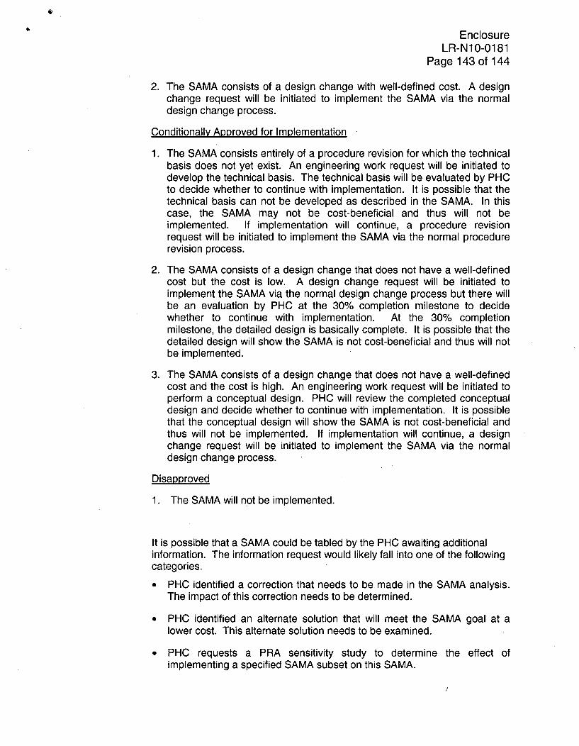
4)
EnclosureLR-N10-0181
Page 143 of 144
2. The SAMA consists of a design change with well-defined cost. A designchange request will be initiated to implement the SAMA via the normaldesign change process.
Conditionally Approved for Implementation
1. The SAMA consists entirely of a procedure revision for which the technicalbasis does not yet exist. An engineering work request will be initiated todevelop the technical basis. The technical basis will be evaluated by PHCto decide whether to continue with implementation. It is possible that thetechnical basis can not be developed as described in the SAMA. In thiscase, the SAMA may not be cost-beneficial and thus will not beimplemented. If implementation will continue, a procedure revisionrequest will be initiated to implement the SAMA via the normal procedurerevision process.
2. The SAMA consists of a design change that does not have a well-definedcost but the cost is low. A design change request will be initiated toimplement the SAMA via the normal design change process but there willbe an evaluation by PHC at the 30% completion milestone to decidewhether to continue with implementation. At the 30% completionmilestone, the detailed design is basically complete. It is possible that thedetailed design will show the SAMA is not cost-beneficial and thus will notbe implemented.
3. The SAMA consists of a design change that does not have a well-definedcost and the cost is high. An engineering work request will be initiated toperform a conceptual design. PHC will review the completed conceptualdesign and decide whether to continue with implementation. It is possiblethat the conceptual design will show the SAMA is not cost-beneficial andthus will not be implemented. If implementation will continue, a designchange request will be initiated to implement the SAMA via the normaldesign change process.
Disapproved
1. The SAMA will not be implemented.
It is possible that a SAMA could be tabled by the PHC awaiting additionalinformation. The information request would likely fall into one of the followingcategories.
* PHC identified a correction that needs to be made in the SAMA analysis.The impact of this correction needs to be determined.
* PHC identified an alternate solution that will meet the SAMA goal at alower cost. This alternate solution needs to be examined.
* PHC requests a PRA sensitivity study to determine the effect ofimplementing a specified SAMA subset on this SAMA.

EnclosureLR-N10-0181
Page 144 of 144
* PHC requests a PRA sensitivity study to determine the effect of alreadyapproved SAMAs on this SAMA.
* PHC requests a PRA sensitivity study to determine the effect of alreadyapproved non-SAMA design changes on this SAMA.
* PHC requests coordination of this SAMA with related Mitigating SystemPerformance Index (MSPI) margin recovery activities. The details of thiscoordination need to be presented to PHC.
A tabled SAMA will be re-presented to the PHC when the requestedinformation has been assembled. At the completion of the PHC review, therewill be no tabled SAMAs.
Each PHC decision and its rationale will be documented in the minutes of theassociated PHC Meeting.
Implementation of Potentially Cost-Beneficial SAMAs
PRA sensitivity studies to find the optimal subset of potentially cost-beneficialSAMAs were not performed due to the large number of possible combinations.One of the purposes of the review of the potentially cost-beneficial SAMAs by thePlant Health Committee (PHC) is to identify potential synergies between SAMAsusing the wide breadth of plant knowledge available on the PHC. The PHC canrequest targeted sensitivity studies to better understand these synergies.
The SAMAs that are "Approved for Implementation" or "Conditionally Approvedfor Implementation" will be ranked with respect to priority and assigned targetyears for implementation. They will be scheduled consistent with this prioritystructure and in accordance with the normal budgetary and work managementprocesses. The implementation schedule may include "hold points" for PRAmodel updates and determination of the effect on the remaining SAMAs. Thus,the PRA model evolves with the plant and the impact on risk for SAMAsconsidered for potential implementation are evaluated based on the latestavailable PRA model of record.
14