horizon install rev b not released - grtavionics.com
TRANSCRIPT

GGRRTT HHOORRIIZZOONN
Models HX, HS & WS
Installation Manual
Rev. A
February 2009
Grand Rapids Technologies, Inc. 3133 Madison Avenue SE
Wyoming MI 49548 616-245-7700
www.grtavionics.com

GRT Horizon Install Manual pg. ii Rev A
INTENTIONALLY BLANK

GRT Horizon Install Manual pg. iii Rev A
FORWARD Welcome to Grand Rapids Technologies’ GRT Horizon! We are pleased that you have chosen our product to meet your flying needs. Visit the Grand Rapids Technologies (GRT) website ( www.grtavionics.com ) for the latest updates and supplemental information concerning the operation of this and other GRT products. This manual describes the installation of GRT Horizon EFIS using the software version shown in the Record of Revisions. Some differences may be observed when comparing the information in this manual to other software versions. Every effort has been made to ensure that the information in this manual is accurate and complete. GRT is not responsible for unintentional errors or omissions in the manual or their consequences. Copyright © 2001 – 2009 Grand Rapids Technologies or its subsidiaries. All rights reserved. Information in the document is subject to change without notice. Grand Rapids Technologies reserves the right to change or improve their products and to make changes in the content of this material without obligation to notify any person or organization of such changes or improvements.

GRT Horizon Install Manual pg. iv Rev A
RECORD OF REVISIONS Rev Date SW Rev Change(s)
A
Feb 2009
32a
Initial Release
LIST OF EFFECTIVE PAGES Page Rev Page Rev Page Rev Page Rev Page Rev Page Rev Page Rev Page Rev ii…….A iii…… A iv…….A v…….A Vi ….A 1-1….A 2-1….A 2-2…...A 3-1….A 3-2…. .A 3-3…. A 4-1….A 5-1….A 6-1….A 6-2……A 6-3…. A 7-1….A 8-1….A 8-2…...A 9-1….A 9-2… A 9-3… A 9-4……A 9-5…... A 9-6…....A 9-7…... A 9-8…... A 9-9….A 9-10….A 9-11….A 9-12….A 9-13.….A 9-14…..A 9-15.….A 9-16.….A 9-17.….A 9-18.….A 9-19.….A 9-20.….A 9-21.….A 9-22.….A 9-23.….A 9-24.….A 9-25.….A 9-26.….A 9-27.….A 9-28.….A 9-29.….A 9-30.….A 10-1….A 11-1….A 12-1….A 13-1….A

GRT Horizon Install Manual pg. v Rev A
Contents CHAPTER 1 GENERAL DESCRIPTION...........................................................1-1
1.1 INTRODUCTION............................................................................................1-1 1.2 DESCRIPTION..............................................................................................1-1 1.3 CERTIFICATION ...........................................................................................1-1
CHAPTER 2 ACCESSORIES AND PACKING LIST.........................................2-1
2.1 TWO DISPLAY PACKAGE ..............................................................................2-1 2.2 3 OR 4 DISPLAY PACKAGES.........................................................................2-2 2.3 SINGLE DISPLAY PACKAGE ..........................................................................2-2
CHAPTER 3 MECHANICAL INSTALLATION ..................................................3-1
3.1 DISPLAY UNIT INSTALLATION........................................................................3-1 3.2 AHRS INSTALLATION ..................................................................................3-1 3.3 MAGNETOMETER INSTALLATION ...................................................................3-1
CHAPTER 4 COOLING CONSIDERATIONS ...................................................4-1
CHAPTER 5 PITOT STATIC CONNECTIONS..................................................5-1
CHAPTER 6 WIRING CONSIDERATIONS.......................................................6-1
6.1 GENERAL ...................................................................................................6-1 6.2 POWER CONNECTIONS ................................................................................6-1 6.3 GROUND CONNECTIONS ..............................................................................6-2 6.4 AHRS, MAGNETOMETER & OAT WIRING......................................................6-2 6.5 OTHER WIRING CONSIDERATIONS ................................................................6-3
6.5.1 Switches ............................................................................................6-3 6.5.2 Warning Light Output .........................................................................6-3 6.5.3 Clock Power.......................................................................................6-3 6.5.4 Audio Output......................................................................................6-3
CHAPTER 7 CHECK OUT ................................................................................7-1
7.1 DISPLAY UNIT CHECK OUT ..........................................................................7-1 7.2 AHRS/AIR DATA COMPUTER AND MAGNETOMETER CHECKOUT PROCEDURE ..7-1
CHAPTER 8 MAGNETOMETER LOCATION VALIDATION ............................8-1
CHAPTER 9 EQUIPMENT INTERCONNECT DETAILS...................................9-1
9.1 SERIAL PORTS............................................................................................9-1 9.1.1 Number ..............................................................................................9-1 9.1.2 Configuring ........................................................................................9-1 9.1.3 Inter-Display Link ...............................................................................9-1 9.1.4 Internal & External ARINC & GPS Modules.......................................9-1 9.1.5 XM Weather.......................................................................................9-2

GRT Horizon Install Manual pg. vi Rev A
9.1.6 AHRS to DU.......................................................................................9-2 9.1.7 Engine Monitoring (EIS).....................................................................9-2 9.1.8 EFIS GPS General Information..........................................................9-2 9.1.9 HX Serial Port / Inter-Display Link / ARINC / Weather .......................9-3
9.2 ANALOG INPUTS..........................................................................................9-4 9.3 USB PORT.................................................................................................9-4 9.4 ARINC INTERFACE .....................................................................................9-4
9.4.1 General ..............................................................................................9-4 9.4.2 ARINC Check Out..............................................................................9-5
9.5 HX WIRING ................................................................................................9-6 9.6 COMMONLY CONNECTED EQUIPMENT...........................................................9-6
9.6.1 Localizer/Glideslope ..........................................................................9-6 9.6.2 Garmin GNS430 / GNS530 / GNS430W / GNS530W........................9-7 9.6 3 Garmin GNS480 ..............................................................................9-12 9.6.4 GPS 155XL / GNC 300XL................................................................9-17 9.6.5 Altitude Encoder ..............................................................................9-21 9.6.6 GTX327 Transponder ......................................................................9-21 9.6.7 GTX 330 Transponder .....................................................................9-22 9.6.8 Other GPS (GPSMAP496, Lowrance etc) .......................................9-23 9.6.9 SL30/SL40 Nav/Com or Com ..........................................................9-24 9.6.10 Autopilot.........................................................................................9-25 9.6.11 Zaon Traffic....................................................................................9-29 9.6.12 CO Guardian..................................................................................9-29
CHAPTER 10 : MOUNTING DIAGRAMS .......................................................10-1
CHAPTER 11 CONNECTOR DESCRIPTIONS...............................................11-1
CHAPTER 12 INTERCONNECT DIAGRAMS.................................................12-1
CHAPTER 13 MAGNETOMETER INSTALLATION........................................13-1

GRT Horizon Install Manual pg. 1-1 Rev A
Chapter 1 GENERAL DESCRIPTION 1.1 Introduction This document provides the physical, mechanical and electrical characteristics and installation requirements for the GRT Horizon EFIS. This document, the Horizon Set Up Guide, the Horizon Users Guide, the Horizon Cable Description, the Horizon Interface Diagram, and the Horizon Connector Definitions document, make up the set of installation documents. Be sure to get the latest versions of these documents from www.grtavionics.com. They are located in Support, Documents. 1.2 Description The GRT Horizon EFIS consists of panel mounted Display Unit(s), separately mounted AHRS and a separately mounted magnetometer. There are several Display Unit options: Standard Resolution Display (MFD-WS) High Resolution Display (MFD-HS) High Resolution 8.7” W x 6.47” H Display (HS-8.4) High Resolution, Accelerated Processor with Synthetic Vision (MFD-HX) Panel Mount Width (7.1”), Radio Rack Width (6.25”) or 8.4 Display (8.7”) Two AHRS packages are available Single AHRS (AHRS-1) Dual AHRS (AHRS-2) (standard with dual display systems) Please consult www.grtavionics.com Support, Documents for the latest dimensions. The display faces are coated with a special coating which is very sensitive to skin oils, waxes and abrasive cleaners. It is very import to clean the display with an eyeglass lens cleaner and a clean lint free cloth. 1.3 Certification The GRT Horizon EFIS is not certified for installation in FAA Type Certificated Aircraft. It is designed and intended for installation in aircraft licensed as Experimental.

GRT Horizon Install Manual pg. 2-1 Rev A
Chapter 2 ACCESSORIES AND PACKING LIST Your EFIS has been carefully inspected and packaged and includes the Display Unit (DU) and associated accessories. Before installing and getting started with your new system, please use the packing list that accompanied the DU and the following paragraphs to ensure that no items are missing and that there is no visible damage. If any parts are missing or damaged, please contact GRT, Inc. or your GRT, Inc. dealer immediately. 2.1 Two Display Package The GRT Horizon two- display package includes two DU’s identified by the rear panel label, Aircraft Multifunction Display, Part Number MFD-HS, MFD-HX, MFD-WS or MFD-HS-8.4. Packaged with the two DUs are:
Two Aircraft Magnetometers One Dual Attitude-Heading Reference System (AHRS-2) OAT probe Wiring Harness, DU to DU, Two DU to AHRS / Magnetometer USB Memory Stick User’s Guide and Reference Manual Installation Manual Set Up Manual
Optionally, DUs may be equipped with: GPS, internal (WS, HS) or external (WS, HS, HX) RAIM GPS, internal (WS, HS) or external (HX) Engine Monitor / EIS XM weather module ARINC 429 interface module (standard in HX) Packaged with GPS DUs is a GPS antenna. Packaged with Engine Monitor DUs are: Engine Information System (EIS-4000 or EIS-6000) Computer Four (4) or Six (6) Exhaust Gas Temperature (EGT) Probes Four (4) or Six (6) Cylinder Head Temperature (CHT) Probes Oil Temperature Sensor Oil Pressure Sensor Manifold Pressure Sensor Fuel Pressure Sensor Fuel Flow Sensor Current Sensor Wiring Harness
GRT Horizon Install Manual pg. 2-2 Rev A
Packaged with XM weather DUs is an GRT XM weather processor and WX Worx weather receiver and antenna. HX Horizon perform weather processing internally so only WX Worx receiver and antenna are supplied. 2.2 3 or 4 Display Packages 3 or 4 display packages will contain the same accessories as a Dual Display package and may be equipped with similar options. DU to DU wiring harness supplied will accommodate the number of DUs supplied. 2.3 Single Display Package The GRT Horizon single display package includes a DU identified by the rear panel label, Aircraft Multifunction Display, Part Number MFD-HS, MFD-HX, MFD-WS or MFD-HS-8.4. Packaged with the DU is:
One Aircraft Magnetometer One Single Attitude-Heading Reference System (AHRS-1) OAT probe Wiring Harness, DU to AHRS,/ Magnetometer USB Memory Stick User’s Guide and Reference Manual Installation Manual Set Up Manual
The same options are available for a single display package as a dual display package, GPS, internal or external, (with or without RAIM) Engine Monitor / EIS XM weather module ARINC 429 interface module (standard in HX) NOTE: The current software version comes installed from GRT, Inc. Any product or software updates can be found on the Grand Rapids Technologies, Inc. website at www.grtavionics.com. Be sure you have the current software installed.

GRT Horizon Install Manual pg. 3-1 Rev A
Chapter 3 MECHANICAL INSTALLATION 3.1 Display Unit Installation Mount the display unit(s) in the desired location in the instrument panel. The main consideration in choosing a location is simply the ability to view the display unit. Since the display is fully sunlight-readable, no consideration for shielding the display unit from sunlight is required.
1. For panel mount style display units, the use of nut plates behind the instrument panel greatly simplifies the task of installing and removing the 4 screws used to retain the display unit in the panel. #6 socket cap stainless steel screws are recommended.
2. For radio rack style display units, the #6 screws on the side of the unit (2 per side) should be used to attach the display unit to the radio rack.
These two FAA Advisory Circulars provide suggestions for positioning display units with respect to visual field and control location: While they are intended for Part 23 (Certified) Airplanes, the information is useful and applicable to Experimental Airplanes also:
• AC23.1311-1B Installation of Electronic Display in Part 23 Airplanes • AC 20-138A Airworthiness Approval of Global Navigation Satellite System
Equipment 3.2 AHRS Installation The AHRS is not affected by wiring, magnetic, heat, temperature or vibration influences. However, good practices suggest that it should be located where these influences are minimized. The pitot and static connections are made to the AHRS, so its location should consider this. It is important that the AHRS is mounted so that the roll, pitch and yaw axes of the AHRS are parallel to the roll, pitch and yaw axes of the aircraft. The precision that this is achieved influences the final performance of the EFIS. There is no requirement that the AHRS roll, pitch or yaw axes be parallel to those of its associated display unit. Be sure to mount the AHRS with the connector toward the rear of the airplane. Observe the label on the AHRS to insure it is oriented correctly. 3.3 Magnetometer Installation Determining the location of the magnetometer requires considerable care because of the magnetometer's sensitivity to magnetic disturbances generated
GRT Horizon Install Manual pg. 3-2 Rev A
by the airplane. No periodic maintenance is required for the magnetometer, although it is desirable to mount it in a location that allows access to it if necessary. The most important consideration when mounting the magnetometer is choosing a location in the airplane that is away from magnetic disturbances. It is quite amazing how sensitive the magnetometer is to these disturbances, and how much error this can cause in the magnetic heading reported by the AHRS. Keep the magnetometer at least 12 inches away from any current carrying wires (such as navigation or landing light wires), and more than 18 inches from ferrous metal, such as the steel mass balance tube that is typically used in the leading edge of ailerons. Use non ferrous hardware (or even double sticky tape) for mounting the magnetometer. Keep the magnetometer as far as possible from transmitting antennas (transponder and especially comm. radio) and their coaxial cables. You can test your proposed magnetometer location prior to mounting the magnetometer itself by placing an ordinary compass at the spot. Then,
1. Turn on and off any electrical equipment whose wiring passes within 2 feet of the magnetometer.
2. Move the flight controls from limit to limit. 3. If the magnetometer is located within 2 feet of retractable landing gear,
operate the landing gear. 4. Operate the comm. radio (transmit) and transponder (IDENT).
Observe the compass while doing each of the above. The goal is no movement, or compass movement of less than 5 degrees. If you observe greater movement, try another location. After the installation and wiring of the magnetometer and display unit(s) is complete, a more sensitive check for magnetic disturbances will be conducted. Each magnetometer and its associated AHRS work together. For this reason, they must be oriented in the same directions, that is, the pitch, roll and yaw axes of the magnetometer and the AHRS need to be parallel. A standard level can be used to orient the magnetometer and AHRS such that they are equal in roll, and in pitch. For yaw, the orientation of these devices should be parallel to the fuselage centerline. In cases where the magnetometer is mounted in the wing, it may be possible to orient the magnetometer parallel to a wing rib, if these ribs are oriented in the wing such that they are parallel to the fuselage centerline. This is quite practical in airplanes such as Van’s RV’s. The following sketch shows this.

GRT Horizon Install Manual pg. 3-3 Rev A
NOTE: Magnetometer and AHRS must be mounted in same attitude relative to each other.
Side View – Correct Front View – Correct Top View - Correct
Side View – Incorrect Front View – Incorrect Top View - Incorrect There is no requirement that the Magnetometer roll, pitch or yaw axes be parallel to those of its associated display unit. Be sure to mount the magnetometer with the connector toward the rear of the airplane. Observe the label on the magnetometer to insure it is oriented correctly. Please refer to www.grtavionics.com Support, Documents for the latest Magnetometer Installation information.

GRT Horizon Install Manual pg. 4-1 Rev A
Chapter 4 COOLING CONSIDERATIONS The GRT Horizon EFIS does not require external cooling. However, as with all electronic equipment, lower operating temperatures extend equipment life. Units in an avionics stack heat each other through radiation, convection and sometimes by direct conduction. Even a stand- alone unit operates at a higher temperature in still air than in moving air. Fans or some other means of moving air around electronic equipment are usually worthwhile. Be certain that cooling air does not contain water – a problem often encountered when using external forced air cooling air. The Horizon HX contains in internal cooling fan. Be sure that there is adequate air available so that it can cool the display unit.

GRT Horizon Install Manual pg. 5-1 Rev A
Chapter 5 PITOT STATIC CONNECTIONS The AHRS contains the Air Data Computer. The ADC requires connection to the aircraft pitot static system. Connections on the display unit take a 1/8 – 27 NPT male fitting. To facilitate installation and removal of the display unit, quick disconnect fittings may be helpful. Connections and the entire pitot static system must be leak tight. Refer to AC 43.13.1B for approved methods to achieve this.

GRT Horizon Install Manual pg. 6-1 Rev A
Chapter 6 WIRING CONSIDERATIONS 6.1 General The cable assemblies supplied with the EFIS includes wires that are certain to be used pre-installed in the connectors. Other connections to the EFIS, which may or may not be used, are not installed in the d-sub connectors. Colored tefzel wires with d-sub connector contacts pre-installed are included for these connections. The cable description diagrams include recommended wire colors for each connection to the EFIS components. When routing the wiring, the following guidelines should be considered.
• Good practices for physical installation of the wiring should be followed, such as grommets where wires pass through sheet metal, considering for chaffing and interference with moving mechanisms. Please refer to FAA AC 43-13-1B, Acceptable Methods, Techniques, and Practices - Aircraft Inspection and Repair.
• Cable lengths should include enough extra length to allow for servicing the equipment. For example, the cables which plug into the display unit should be long enough to allow them to be connected to display unit with the display unit not installed in the instrument panel.
• In general, routing of the wiring is not critical, as the EFIS is designed to be tolerant of the electrical noise and other emissions typically found in aircraft. Some consideration should be given to avoid routing wires near antennas, or other locations that could impart high levels of electromagnetic signals on the wiring. This is especially true in composite airframes since, unlike aluminum airframes, composites offer no shielding of electromagnetic energy.
• The checkout procedures should be completed to verify the EFIS is not affected by radio transmissions on any frequency.
6.2 Power Connections The display units each include 3 isolated power input connections. This allows redundant power sources, such as a main and secondary bus. The display units consume less than 2 amps each, making even a small 3 Amp-Hour gel cell a suitable emergency source. The majority of the current flow into the display unit will occur on the bus with the highest voltage. So if the voltage of the main bus or power source falls below that of the secondary bus or power supply, the secondary bus will power the display units and operation will not be interrupted. Since it is desirable to not have the display units and AHRS connected to the power supply supplying power to the engine starter during the engine start (to maximize the current available for the starter, and possibly extend the life of the CCFL backlight in the display unit),

GRT Horizon Install Manual pg. 6-2 Rev A
this feature allows the fitting of a small (3-5AH) auxiliary battery to one of the power input connections provide power to the EFIS during engine start. If an auxiliary battery is fitted, provisions should be made to keep it charged. The configuration of the power supplied to the display unit(s) is left to the installer. Considerations such as the number of power buses, the desire or not to supply one piece of equipment with power from redundant buses (which in theory allows the possibility of that device being unaffected by failure of a bus), the configuration of the electrical system with respect to backup equipment, and so on, may dictate the best configuration for a particular airplane. No provision is included within the display units for a power switch. If a power switch is desired for the EFIS, the +12V power should be controlled with the switch (not ground). The display units include internal thermally-activated fuses. This protects the equipment from internal electrical faults. Power supplied to the EFIS must pass through an external fuse or circuit breaker. It should be sized to allow at least 2 amps per display unit, with a maximum rating of 5 amps. The AHRS and display units monitor all of their power inputs, and alarms are available to annunciate the loss of any power source that was provided and is expected to be working according to the “General Setup” menu. 6.3 Ground Connections The cable assembly provided includes 20 or 22 gauge wire for the ground return of the display units. This will result in a voltage drop of about 0.015 V/foot, which is acceptable for wire lengths up to 10 feet. 6.4 AHRS, Magnetometer & OAT Wiring Typically, the AHRS & magnetometer cable supplied with the EFIS will not have a d-sub connector installed on DU or magnetometer cable end. This makes it easier to route this cable through the airplane. After the cable has been routed, the wires can be cut to length if desired, although new d-sub pins would need to be installed. If the wires are not cut, inspect the d-sub connector pins to verify they have not been damaged. Insert the indicated wire color into the appropriate d-sub connector housing hole according to the cable description diagram. If desired, the crimp-type d-sub connector can be replaced with a solder-type connector. All magnetometer connections are made directly to the mating AHRS. This wiring includes the power connections necessary for the magnetometer to operate. Each AHRS and magnetometer pair is calibrated together for optimal accuracy, and thus this paring should be maintained.

GRT Horizon Install Manual pg. 6-3 Rev A
An OAT sensor may be connected to the AHRS package to provide OAT for true airspeed calculations. More commonly, the OAT is connected to EIS. 6.5 Other Wiring Considerations 6.5.1 Switches Depending on the other equipment installed in the airplane, switches may be necessary or desirable for the following functions: One may wish to install a switch to allow the autopilot to be controlled by either the EFIS, or directly from the GPS. The benefit of this switch is to allow the GPS to control the autopilot in the event the display unit which normally commands the autopilot is not functioning. 6.5.2 Warning Light Output A warning output is provided to drive an external warning light. This output provides a path to ground when active, thus the indicator should be wired with one of its terminals to aircraft power, and the other to this output. The maximum current that can be controlled by this output is 0.2 amps. 6.5.3 Clock Power Horizon installations require the clock to be powered at all times. 6.5.4 Audio Output An audio output is provided. Future growth is planned to allow this output to provide a warning tone, or possibly other type of audio output. This output may be connected to a spare input on the aircraft’s intercom system. Volume level will be controlled by menu settings within the display unit.

GRT Horizon Install Manual pg. 7-1 Rev A
Chapter 7 CHECK OUT 7.1 Display Unit Check Out
1. Apply Power to the display unit. The LCD may flicker, and within 10 seconds, the display should show the first page.
2. If multiple power buses connect to the display unit, turn off the display unit, and apply power from each bus individually.
3. For dual or multiple display systems, repeat the above steps for the other display unit(s).
7.2 AHRS/Air Data Computer and Magnetometer Checkout Procedure
1. Apply power to the display unit. 2. Proper operation of the AHRS and magnetometer is indicated as follows:
a. The display unit shows altitude and airspeed tapes. b. Attitude and heading data appears on the screen at the completion
of the alignment period (typically less than 2 minutes). c. No "ATTITUDE FAIL" message is shown on the PFD screen. d. No failure messages are listed in the status page (accessible from
the "Status" softkey on the PFD screen). 3. Select the “Set Menu” from the softkeys, and select the “AHRS
Maintenance” page. 4. Verify AHRS communications status is valid, and AHRS status is OK.
Verify the AHRS is receiving serial communications from the display unit by observing that no data fields are grayed out.
5. Scroll down this screen to the “Magnetic Heading” field. This is the raw magnetic heading sensed by the magnetometer.
6. To verify the magnetic heading is reasonable, the following conditions must be met.
a. The roll and pitch attitude data must be accurate. b. The magnetometer must be in the same attitude as the AHRS. c. The magnetometer must have been electrically connected to the
AHRS when the Display Unit was turned on. d. The magnetic heading should be accurate within 30 degrees for
any direction in which the airplane is pointed. This can be verified by observing the “Magnetic Heading” data while positioning the airplane in different directions. If this accuracy is not achieved, it is likely due to a wiring error of the magnetometer connector, or magnetic disturbances in the vicinity of the magnetometer.
7. The magnetometer location validation should be performed. Complete calibration must also be performed prior to flight. Refer to the GRT Horizon Users Guide for complete magnetometer calibration instructions
8. For dual or multiple display systems, repeat the above steps for the other Display Unit/AHRS pairs.
GRT Horizon Install Manual pg. 8-1 Rev A
Chapter 8 Magnetometer Location Validation Select “Set Menu”, “AHRS Maintenance”, and locate the Magnetic Heading field on this screen. This shows the magnetic heading data provided by the magnetometer. (The heading data shown on the normal display screens is the gyro slaved heading, which responds slowly to magnetic heading changes.) Observe this reading and verify it does not change by more than +/- 2 degrees while doing the following:
• Turn on and off any equipment whose wiring passes within 2 feet of the
magnetometer. • Move the flight controls. • If the magnetometer is located near retractable landing gear, operate the
landing gear. • Operate the comm. radio (transmit) and transponder (IDENT).
Before performing the magnetometer calibration procedure, the approximate accuracy of the uncorrected magnetic heading data must be checked. While the calibration procedure can remove errors as large as 125 degrees, accuracy is improved if the location chosen for the magnetometer requires corrections of less than 30 degrees. To check the accuracy of the uncorrected magnetic heading, select the magnetometer calibration page from the AHRS maintenance page by changing the selection next to "Magnetometer Calibration". While on this page, rotate the airplane 360 degrees. A red graph will appear on this page showing the errors showing the calculated errors. If errors of greater than 30 degrees are observed, they may be caused by magnetic disturbances near the magnetometer, such a ferrous metal, magnetic fields from electric motors, radiation from transmitting antennas or the magnetometer orientation is not the same as the AHRS. (For every 1 degree of misalignment between the magnetometer and the AHRS, approximately 3 degrees of heading error can be expected.) Location Problems The most common cause is simply magnetic disturbances near the magnetometer. This can be caused by ferrous metal (any metal that a magnet will stick to), control cables, or cable carrying electrical currents, such as navigation or landing lights, or transmitting antennas (comm., transponder) being too close to the magnetometer. If there is any doubt about a location, try moving the magnetometer to another location. Use tape or other temporary means to hold it in place, roughly aligned with the orientation of the AHRS, and repeat the test. Wiring Problems

GRT Horizon Install Manual pg. 8-2 Rev A
1. Some wiring problems will be detected by the AHRS built-in-test functions. The will result in an AHRS Attitude Fail Message, and an "AHRS: Magnetometer X, Y or Z-Axis Failed" message on the status page that is accessed by the STATUS button from any page. If this message is present, the wiring to the magnetometer should be checked. 2. It is also possible that no built-in-test failure is reported, but the wiring is still incorrect. This can occur if the magnetometer X, Y, Z inputs are swapped. To check for this, point the airplane at various directions listed in the table below, with the magnetometer in an approximately level position (it may need to be removed from the airplane and held by hand). Use the AHRS Maintenance page to observe the "Magnetometer X, Y, Z Raw Data". The following should be observed. Direction X Raw Data* Y Raw Data* Z Raw Data* Magnetic North Positive Value
above 1000 Between -500 and +500
Greater than positive 1500**
Magnetic East Between -500 and +500
Positive Value above 1000
Greater than positive 1500**
Magnetic South Negative Value less than -1000
Between -500 and +500
Greater than positive 1500**
Magnetic West Between -500 and +500
Negative Value less than -1000
Greater than positive 1500**
* The raw data readings will appear to shift left and right on the screen once per second, as the sign change for a brief moment. This is normal, and the brief sign changes should be ignored when using this table of the expected readings. ** The Z Raw data will be greatly influenced by where on the earth the test is performed. Positive values will be observed in the northern hemisphere and negative values in the southern hemisphere.

GRT Horizon Install Manual pg. 9-1 Rev A
Chapter 9 EQUIPMENT INTERCONNECT DETAILS 9.1 Serial Ports 9.1.1 Number The GRT Horizon HS & WS have 6 serial ports. Serial Port 1 and Serial Port 2 are High Speed. The GRT Horizon HX has 8 high speed serial ports. The current pin outs are available in the Support, Documents section of www.grtavionics.com. 9.1.2 Configuring Each Serial Port is configurable (Settings Menu, General Setup) as to assignment and baud rate, so the EFIS may be configured to the equipment attached to it. Detailed instructions for configuring Serial Ports are in the Horizon SetUp Guide. 9.1.3 Inter-Display Link Display units communicate between themselves so that most entries made during flight can be made from any display unit, and will be applied to all. The data that is transmitted on the Inter-Display Unit Link is user defined (Settings Menu, General Setup). In general one should try to have data from connected equipment sent directly to each DU so that data is available in case a DU fails. However since a limited number of Serial ports are available, inevitably some data must be shared via the Inter-Display Unit Link. If possible, the GPS data from an installed panel mount GPS is connected to each DU. XM weather cannot be shared over the link. The Inter-Display Unit Communication is accomplished by connecting a serial output port to a serial input port on each display unit (WS and HS Models). Horizon HX use Ethernet rather than Serial ports for Inter Display Unit communications. If more than two HX are connected, it is necessary to use an Ethernet Hub. An HX will share all inputs with another HX over the Ethernet link, including Weather. 9.1.4 Internal & External ARINC & GPS Modules Each HS or WS Horizon DU can have at most one internal module installed, ARINC or GPS. The internal module is connected to Serial Port 1. If the internal module is ARINC, the ARINC module will communicate with the Horizon and also provide a Serial port for other uses. This serial port will be degraded to low speed. If the internal module is a GPS, Serial Port 1 is not available for other use.

GRT Horizon Install Manual pg. 9-2 Rev A
In a dual DU system, it is common for the PFD DU to have an internal ARINC and the MFD DU to have a GPS. One might consider a second ARINC module in the MFD DU if two GNS430/530/480 receivers are installed. All Horizon HX have a built in ARINC module whose connection is independent of the eight serial ports and does not affect the operation of Serial port 1 Horizon WS & HS DUs may be equipped with internal or external GPS or RAIM GPS modules. The Horizon HX may be equipped with an external GPS or RAIM GPS module. In all cases, the GPS module will use one serial port (In & Out). Please note that even with RAIM GPS, the GRT Horizon EFIS does not meet the certification requirements for stand alone use for IFR flight. 9.1.5 XM Weather In HS or WS Horizon DUs, the GRT XM Weather Processor must be connected to a high speed serial port (1 or 2). If a DU has no internal module installed, either serial port may be used. If an internal module is installed, the GRT XM Weather Processor must be connected to Serial Port 2. In a dual display system, if you desire to display weather on both DUs, the output from the XM Weather Module must be connected to a high speed serial port IN on both displays since weather data cannot be transmitted on the Inter-Display Link. A high speed Serial port OUT from only one display is connected to the XM Weather Module and is used to control the XM weather processor. 9.1.6 AHRS to DU Multiple display systems are supplied with one dual AHRS package. Each AHRS in the dual AHRS package has four Serial Outputs and one Serial Input. Each DU receives data from each AHRS, using two of the DUs Serial Inputs. A DU can control only one AHRS. So a Serial Output from one DU controls one AHRS and a Serial Output from the other DU controls the other AHRS. AHRS control is used to command magnetometer calibration, to enter altimeter corrections, or update AHRS software. Multiple display (3 or more) systems have two displays wired to a dual AHRS as described above. The other DU’s are supplied a Serial In from each AHRS. 9.1.7 Engine Monitoring (EIS) Engine monitoring (EIS) systems use one serial port IN. However, if possible, provide a serial port OUT connection for future considerations. 9.1.8 EFIS GPS General Information

GRT Horizon Install Manual pg. 9-3 Rev A
Many panel mount GPS receivers require altitude and air data information. This is the same information used by transponders. It is usually Fuel/Air Data Z Format and supplied by a Serial Out port on the EFIS. It is common to provide the EFIS with GPS data from the GPS receiver. The data may be used for GPS position (removes need for GRT GPS module) and to transmit Flight Plans from the GPS receiver to the EFIS. Panel mount GPS (GNS430 etc) are usually in GPS Aviation format while hand held GPS (GPSMAP 396 etc) are in NEMA format. The data is sent to a serial port IN. 9.1.9 HX Serial Port / Inter-Display Link / ARINC / Weather All Horizon HX serial ports are high speed and all serial inputs, including weather are shared over the Ethernet link. All Horizon HX have a built in ARINC module whose connection is independent of the eight serial ports and does not affect the operation of Serial port 1. The Horizon HX processes XM weather data internally; it does not use the GRT XM Weather processor. The Horizon HX connects to the WX Works receiver by USB interface and cable, rather than one of the eight serial ports. The connector diagrams on the website provide general suggestions for serial port assignment. You may use any serial port with baud rates compatible with the equipment connected to it. Note that the baud rate for a port is the rate for both input and output. A port configured for 9600 baud will receive data at 9600 baud only and will send data only at 9600 baud. Here is a table of common baud rates for commonly connected equipment.
Serial
Unit Baud Rate Display Unit Format(Notes) Unit Settings
AHRS 19200
Inter-Display Link 19200
GRT GPS 4800 NMEA
GRT Weather 115200 Port 2 Horizon, Port 4 Sport
EIS 9600
SL30 9600
SL40 9600
GNS430 9600 Aviation/MapCom Shadin FADC
GNS530 9600 Aviation/MapCom Shadin FADC
GNS480 9600 Aviation/MapCom Shadin FADC
GTX327 9600 FAD (Z Format) Shadin FADC w/ ALT

GRT Horizon Install Manual pg. 9-4 Rev A
GTX330 9600 FAD (Z Format) Shadin FADC w/ ALT
GNC300 9600 Aviation/MapCom Shadin FADC
GNC250 9600 Aviation/MapCom Shadin FADC
TruTrak 4800 or 9600 A/P NMEA or A/PAviation
GPSMap196 Configure? NMEA
GPSMap296 Configure? NMEA
GPSMap396 Configure? NMEA
MX20 Configure?
Autopilot Configure NMEA
Zaon 57600
Zaon 9600
CO Guardian 9600 9.2 Analog Inputs The GRT Horizon has 8 user configurable analog inputs. Similar to the Serial Ports, the Analog Inputs may be configured to fit the attached equipment. Common uses include such items as Flap Position, Trim Position etc, although any 0-12 volt signal may be displayed. See www.grtavionics.com Support, Documents for more details. 9.3 USB Port Each HS & WS display unit has a USB port on the rear. It is used to record flight data to a memory stick (also called a USB drive) and to load software updates from a memory stick. USB extension cables are available so that a receptacle for a USB memory stick can be located at a convenient place in the cockpit. The GRT Horizon HX has two USB ports. Both are master ports. One may be used to interface to the XM weather receiver (GRT XM Weather processor not used) while the other is used to record flight data or to load software. 9.4 ARINC Interface 9.4.1 General The optional (Horizon HS & WS) ARINC interface provides additional features to interface with GPS receivers and autopilots. The GRT Horizon HX comes standard with the ARINC interface. The connections are made via 9 pin D Sub connector. Please refer to www.grtavionics.com for up to date details.
GRT Horizon Install Manual pg. 9-5 Rev A
The ARINC 429 adapter provides 2 serial inputs and 1 serial output that conform to the ARINC 429 serial communication standard. The inputs may be configured for various uses according to the other equipment installed in the airplane as described below. Each input may be configured for any of the possible functions. The ARINC 429 output is used by the EFIS to generate data usable by a variety of equipment, such as autopilots and GPS receivers. The ARINC 429 output can be connected to as many ARINC 429 inputs (receivers) as desired, GNS430 and Autopilot for example. GRT Horizon uses of ARINC include control of an autopilot using GPSS/GPSV mode, to accept TIS information from a GTX 330 transponder, and exchange of information with GPS and Nav receivers. 9.4.2 ARINC Check Out If the ARINC 429 input and/or outputs are wired, these interfaces must be verified. ARINC 429 Inputs 1. Select the "SET MENU", "Display Unit Maintenance" menu. Scroll down near the end of this menu to locate the "ARINC Status" setting. Select the ARINC Status menu by selecting the "Change to activate menu", and pushing the knob. This menu will show if data is being received, and if it is valid. If the ARINC Counter is changing for each input that has been wired to equipment in the airplane, and this equipment is transmitting ARINC data, the counter will be increasing. The counter can increase even if the input is wired backwards, so the data must also be verified. Verifying Valid Data The status menu will show labels for data it expects to receive. For each device that sends ARINC data to the EFIS, if any data can be confirmed, the interface can be assumed 100% functional. For example, if a Garmin 430 is wired to the EFIS, it will send the VOR/ILS frequency tuned on the radio. If the ARINC status page shows the same frequency displayed on the G430, the interface is functional. Troubleshooting If the counter is not changing, the device that transmits the data is not sending data, or the electrical connection is open circuit for one of both of the 429 electrical connections.

GRT Horizon Install Manual pg. 9-6 Rev A
If the counter is counting, but no valid data is observed, the two 429 electrical connections are reversed, or are not from the same ARINC output. 9.5 HX Wiring The HX Horizon has the same 25 pin d sub connectors as do the HS & WS Horizons and all the pin connections are identical. So if HS or WS displays are being replaced by HX displays, merely copy the configuration data to a memory stick (Settings Menu, Display Unit Maintenance), change the displays and copy the old configuration to the HX displays. If HX DUs are being installed in a new install, to take full advantage of the current and planned features of the HX Horizon,
1. Use the provided Ethernet ports for Inter-Display Link. 2. Connect Wx Worx XM Weather receiver (no GRT Processor) to one of the
USB ports. Connect peripheral equipment to Serial Ports and Analog Inputs in accordance with documentation. 9.6 Commonly Connected Equipment Here is connection information for commonly connected equipment. 9.6.1 Localizer/Glideslope The localizer/glideslope deviation indicators (scales or needles) provided on the EFIS can be driven from any Garmin ILS/GS receiver or combination Nav/GPS receivers (GNS430/530,480, etc). ARINC interface is not required. Specific wiring recommendations are provided for GNS430/530/480 systems below. When Nav receivers are connected to the EFIS, the localizer and glideslope deviation and flag connections are made to the EFIS localizer/glideslope deviation and flag inputs. If the Nav receiver includes an “ILS Tuned” output, indicating an ILS frequency is selected on the Nav radio, connect this to an Analog input on the Display unit (Analog 1 recommended) as shown in the following tables. These inputs require practically no power from the Nav receiver’s outputs, allowing the Nav receiver to be wired to as many display units as desired. Nav heads may also be wired to these connections. For redundancy purposes, it is desirable to connect these signals to all display units.

GRT Horizon Install Manual pg. 9-7 Rev A
Note that the operation of the HSI for VOR and GPS indications is performed within the Horizon, independent of the Nav receiver. Display Unit Connector A Connections Mating Connector: 25-pin Female D-sub (Instrument has 25-pin male D-sub) EFIS Display Unit Pin
Function
Notes
A-6 Localizer Deviation + Left Input A-7 Localizer Deviation + Right Input A-8 Glideslope Deviation + Down A-9 Glideslope Deviation + Up A-10 Localizer Valid – Input A-11 Localizer Valid + Input A-12 Glideslope Valid – Input A-13 Glideslope Valid + Input Display Unit Connector B Connections Mating Connector: 25-pin Male D-sub (Instrument has 25-pin Female D-sub) EFIS Display Unit Pin
Function
Notes
B-21 Analog Input 1 – ILS Tuned Input Pull-Up Required** ** Pull-Up required indicates a pull-up resistor is required. If this input is also connected to another system, such as a Nav head, the pull-up resistor is not required as long as this other system is installed. If this signal is not shared with other systems, a 10k ohm resistor, connected with one lead to aircraft 12V power, and the other lead “tee-d” into this connection is required. 9.6.2 Garmin GNS430 / GNS530 / GNS430W / GNS530W Note: In this Chapter (9.6.2), wherever Garmin GNS430 is used, it applies to any of the four receivers, GNS430, GNS430W, GNS530 or GNS530W. The following guidelines are provided for reference purposes only. They provide suggested methods for connecting this GPS to the EFIS display unit to allow optimal performance of both units. The interface between this GPS and the EFIS allows for:
• GPS position, groundspeed and ground track to be provided to the EFIS. • GPS flight plan data to the EFIS (although curved paths such as DME
arcs, procedure turns and holding patterns are not displayed)
GRT Horizon Install Manual pg. 9-8 Rev A
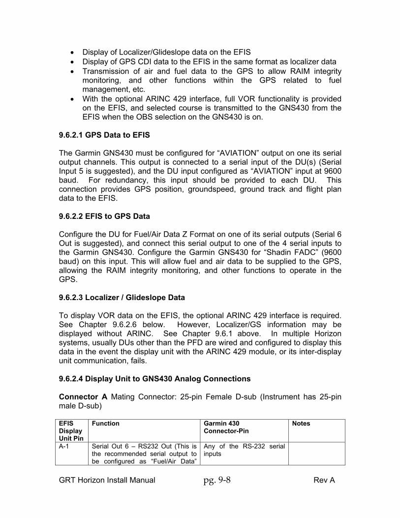
• Display of Localizer/Glideslope data on the EFIS • Display of GPS CDI data to the EFIS in the same format as localizer data • Transmission of air and fuel data to the GPS to allow RAIM integrity
monitoring, and other functions within the GPS related to fuel management, etc.
• With the optional ARINC 429 interface, full VOR functionality is provided on the EFIS, and selected course is transmitted to the GNS430 from the EFIS when the OBS selection on the GNS430 is on.
9.6.2.1 GPS Data to EFIS The Garmin GNS430 must be configured for “AVIATION” output on one its serial output channels. This output is connected to a serial input of the DU(s) (Serial Input 5 is suggested), and the DU input configured as “AVIATION” input at 9600 baud. For redundancy, this input should be provided to each DU. This connection provides GPS position, groundspeed, ground track and flight plan data to the EFIS. 9.6.2.2 EFIS to GPS Data Configure the DU for Fuel/Air Data Z Format on one of its serial outputs (Serial 6 Out is suggested), and connect this serial output to one of the 4 serial inputs to the Garmin GNS430. Configure the Garmin GNS430 for “Shadin FADC” (9600 baud) on this input. This will allow fuel and air data to be supplied to the GPS, allowing the RAIM integrity monitoring, and other functions to operate in the GPS. 9.6.2.3 Localizer / Glideslope Data To display VOR data on the EFIS, the optional ARINC 429 interface is required. See Chapter 9.6.2.6 below. However, Localizer/GS information may be displayed without ARINC. See Chapter 9.6.1 above. In multiple Horizon systems, usually DUs other than the PFD are wired and configured to display this data in the event the display unit with the ARINC 429 module, or its inter-display unit communication, fails. 9.6.2.4 Display Unit to GNS430 Analog Connections Connector A Mating Connector: 25-pin Female D-sub (Instrument has 25-pin male D-sub) EFIS Display Unit Pin
Function Garmin 430 Connector-Pin
Notes
A-1 Serial Out 6 – RS232 Out (This is the recommended serial output to be configured as “Fuel/Air Data”
Any of the RS-232 serial inputs

GRT Horizon Install Manual pg. 9-9 Rev A
output to the GNS-430.) A-6 Localizer Deviation + Left Input P4001-21* A-7 Localizer Deviation + Right Input P4001-22* A-8 Glideslope Deviation + Down P4001-28* A-9 Glideslope Deviation + Up P4001-27* A-10 Localizer Valid – Input P4001-24* A-11 Localizer Valid + Input P4001-23* A-12 Glideslope Valid – Input P4001-30* A-13 Glideslope Valid + Input P4001-29* A-22 Serial Input 5 – RS232 GPS Data In
(Aviation Format) (Suggested Port) Any one of the RS-232 serial outputs
*These connections are not required on a DU with an ARINC 429 Module installed and the GNS430 VOR/ILS/GS ARINC output connected to the ARINC 429 Module. These connections should be made to all display units which do not include the ARINC 429 Module so that this data is provided to the display unit in the event the display unit with the ARINC429 module, or its inter-display unit communication, fails. Connector B Mating Connector: 25-pin Male D-sub (Instrument has 25-pin Female D-sub) EFIS Display Unit Pin
Function Garmin 430 Connector-Pin
Notes
B-21 Analog Input 1– Reserved for future growth/ILS Tuned Input
P4006-29* Pull-Up Required**
B-20 Analog Input 2 – GPS Deviations Active (true when low)
P4001-2* Pull-Up Required**
B-19 Analog Input 3 – VOR/ILS Deviations Active (true when low)
P4001-1* Pull-Up Required**
B-18 Analog Input 4 - OBS Select (this connection may not be required)
P4001-7* Pull-Up Required**
*These connections are not required on a DU with an ARINC 429 Module installed and the GNS430 VOR/ILS/GS ARINC output connected to the ARINC 429 Module. These connections should be made to all display units which do not include the ARINC 429 Module so that this data is provided to the display unit in the event the display unit with the ARINC429 module, or its inter-display unit communication, fails. ** Pull-Up required indicates a pull-up resistor is required. If this input is also connected to another system, such as a Nav head, the pull-up resistor is not required as long as this other system is installed. If this signal is not shared with other systems, a 10k ohm resistor, connected with one lead to aircraft 12V power, and the other lead “tee-d” into this connection is required.

GRT Horizon Install Manual pg. 9-10 Rev A
9.6.2.5 Configuring the Display Unit for GNS430 Analog Inputs The display unit must be configured according to the following table to enable it to read the above analog signals. Set Menu Page Setting Value General Setup Analog 1 Function ILS Tuned General Setup Discrete 1 Active Voltage Low General Setup Analog 2 Function GPS Deviation Active General Setup Discrete 2 Active Voltage Low General Setup Analog 3 Function VOR/ILS Deviations Active General Setup Discrete 3 Active Voltage Low General Setup
Analog VOR/ILS Inputs Nav1 (or Nav2 if this display unit is wired to Nav receiver 2.)
General Setup Serial Port 6 Out (Suggested Port)
Fuel/Air Data Z Format
General Setup Serial Port 6 Rate 9600 General Setup Serial Port 5 In
(Suggested Port) GPS Aviation
General Setup Serial Port 5 Rate 9600 9.6.2.6 Display Unit to GNS430 ARINC 429 Connections for VOR/ILS/GS The following connections to the GNS430 allow the EFIS to receive VOR/ILS/GS navigation information from the GNS430 via ARINC. The data transmitted to the EFIS also includes ILS data, making it unnecessary to connect the analog localizer and glideslope deviation and validity signals (connections shown in tables above except for Serial 6 Out, Fuel/Air Data and Serial 5 In, GPS Aviation). ARINC 429 Adapter Pin
Function GNS430 Pin GNS430 Function
C-3 (or C-1)* VOR/ILS Input J4006-24 ARINC 429 A - VOR/ILS Output
C-4 (or C-2)* VOR/ILS Input J4006-23 ARINC 429 B - VOR/ILS Output
C-5 EFIS Output May also connect to other devices, such as an autopilot
J4001-48** ARINC IN 1A (J4001-50 ARINC IN 2A)
ARINC 429 A Channel 1 EFIS Input.
C-9 EFIS Output May also connect to other devices, such as an autopilot
J4001-49** ARINC IN 1B (J4001-51 ARINC IN 2B)
ARINC 429 B - Channel 1EFIS Input.
* C-3, C-4 must be used as a pair, or C-1,C-2 must be used as a pair. ** If this input to the G430 is used by other equipment, the other ARINC 429 input may be used.

GRT Horizon Install Manual pg. 9-11 Rev A
If desired, the ARINC output wires from the EFIS may connect to a switch for the autopilot data source as mentioned in Chapter 6.5.1. See Chapter 9.6.10 for more detail. 9.6.2.7 Configuring the Display Unit for ARINC Data Input (VOR/ILS/GS) The display unit must be configured according to the following table to enable it to read the above ARINC signals: Set Menu Page Setting Value General Setup ARINC Module Connected* Yes General Setup ARINC Receive Rate* Low (A/P Dependent) General Setup ARINC Transmit Rate Low General Setup ARINC VOR/ILS Inputs* Nav1 (or Nav 2 if this display
unit is connected to number 2 GNS430/530)
9.6.2.8 Configuring the GNS430 Refer to the GNS430 installation manual, and configure the serial input used to receive fuel / air data for FADC w/ALT format, and the serial output used to send GPS data for “Aviation” format. Setting Value RS232 Input - Channel used for fuel/air data input from display unit.
Shadin-FADC
RS232 Output - Channel Used for GPS Output to display unit.
Aviation
VOR/LOC/GS ARINC 429 - TX Low (Autopilot Requirement) VOR/LOC/GS ARINC 429 - RX Low (Autopilot Requirement) ARINC429 Input - Channel 1 (or the channel connected to ARINC429 Module Output)
Speed Low Speed Data EFIS/Airdata (Provides selected course and air data.)
9.6.2.9 Display Unit to GNS430 ARINC 429 for GPS Since the Horizon database does not contain approach information, the Horizon cannot provide lateral steering for procedure turns, DME arcs, holding patterns etc. However, the GNS430 can provide GPS position, flight plan data, lateral deviation, vertical deviation, roll commands and mode selection to the Horizon over an additional ARINC connection (ARINC GPS), just like the VOR/ILS/GS ARINC connection. This information allows the EFIS to provide VNAV functions for an approach and follow roll commands from the GNS430 while still controlling pitch commands. This eliminates the need for analog inputs for deviation and requires less switching of the autopilot output between the EFIS and the GNS430. With this feature, the external switch (see Chapter 6.5.1) can be left in the EFIS position unless there is an EFIS failure. See the Horizon Users Manual, Chapter 5.3.1, GNAV for how to use these features.

GRT Horizon Install Manual pg. 9-12 Rev A
9.6.2.10 Display Unit to GNS430 ARINC 429 Connections for GPS ARINC 429 Adapter Pin
Function GNS430 Pin GNS430 Function
C-1 GPS Input J4001-46 ARINC 429 A - GPS Output May also connect to other devices, such as an autopilot
C-2 GPS Input J4001-47 ARINC 429 B – GPS Output May also connect to other devices, such as an autopilot
If desired, the ARINC output wires from the GNS430 may connect to a switch for the autopilot data source as mentioned in Chapter 6.5.1. See Chapter 9.6.10 for more detail. 9.6.2.11 Configuring the Display Unit for ARINC Data Input (GPS) The display unit must be configured according to the following table to enable it to read the above ARINC signals: Set Menu Page Setting Value General Setup ARINC Receive Rate* To match GNS430 rate General Setup ARINC GPS Inputs* GPS1 (or GPS 2 if this display
unit is connected to number 2 GNS430/530)
9.6.2.12 Configuring the GNS430 for ARINC (GPS) Refer to the GNS430 installation manual, and configure the serial input used to receive fuel / air data for FADC w/ALT format, and the serial output used to send GPS data for “Aviation” format. Setting Value RS232 Input - Channel used for fuel/air data input from display unit.
Shadin-Fadc
RS232 Output - Channel Used for GPS Output to display unit.
Aviation
ARINC CONFG OUT DATA GAMA 429 ARINC CONFG SPEED Match VOR/LOC/GS output ARINC CONFG VNAV Enable labels ARINC CONFG SDI LNAV 1 9.6 3 Garmin GNS480 The following guidelines are provided for reference purposes only. They provide
GRT Horizon Install Manual pg. 9-13 Rev A
suggested methods for connecting this GPS to the EFIS display unit to allow optimal performance of both units. The interface between this GPS and the EFIS allows for:
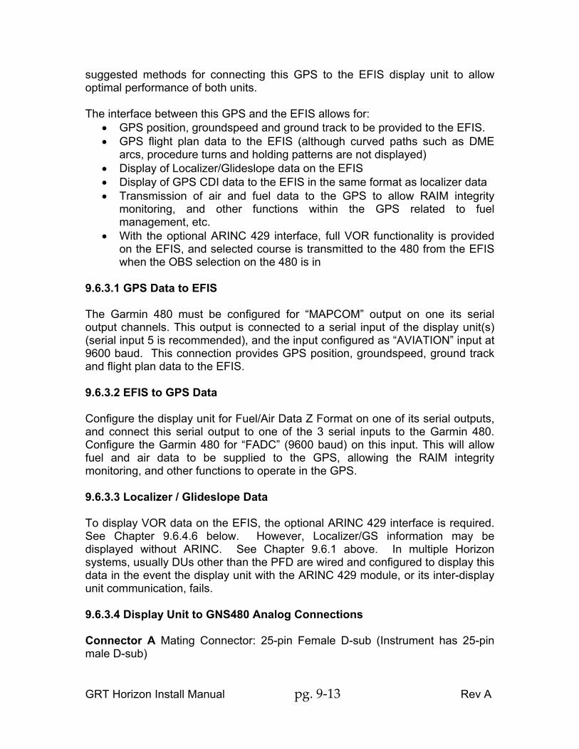
• GPS position, groundspeed and ground track to be provided to the EFIS. • GPS flight plan data to the EFIS (although curved paths such as DME
arcs, procedure turns and holding patterns are not displayed) • Display of Localizer/Glideslope data on the EFIS • Display of GPS CDI data to the EFIS in the same format as localizer data • Transmission of air and fuel data to the GPS to allow RAIM integrity
monitoring, and other functions within the GPS related to fuel management, etc.
• With the optional ARINC 429 interface, full VOR functionality is provided on the EFIS, and selected course is transmitted to the 480 from the EFIS when the OBS selection on the 480 is in
9.6.3.1 GPS Data to EFIS The Garmin 480 must be configured for “MAPCOM” output on one its serial output channels. This output is connected to a serial input of the display unit(s) (serial input 5 is recommended), and the input configured as “AVIATION” input at 9600 baud. This connection provides GPS position, groundspeed, ground track and flight plan data to the EFIS. 9.6.3.2 EFIS to GPS Data Configure the display unit for Fuel/Air Data Z Format on one of its serial outputs, and connect this serial output to one of the 3 serial inputs to the Garmin 480. Configure the Garmin 480 for “FADC” (9600 baud) on this input. This will allow fuel and air data to be supplied to the GPS, allowing the RAIM integrity monitoring, and other functions to operate in the GPS. 9.6.3.3 Localizer / Glideslope Data To display VOR data on the EFIS, the optional ARINC 429 interface is required. See Chapter 9.6.4.6 below. However, Localizer/GS information may be displayed without ARINC. See Chapter 9.6.1 above. In multiple Horizon systems, usually DUs other than the PFD are wired and configured to display this data in the event the display unit with the ARINC 429 module, or its inter-display unit communication, fails. 9.6.3.4 Display Unit to GNS480 Analog Connections Connector A Mating Connector: 25-pin Female D-sub (Instrument has 25-pin male D-sub)

GRT Horizon Install Manual pg. 9-14 Rev A
EFIS Display Unit Pin
Function Garmin 480 Connector-Pin
Notes
A-1 Serial Out 6 – RS232 Out (This is the recommended serial output to be configured as “Fuel/Air Data” output to the GNS-480.)
Any of the RS-232 serial inputs
A-6 Localizer Deviation + Left Input P7-14* A-7 Localizer Deviation + Right Input P7-13* A-8 Glideslope Deviation + Down P7-31* A-9 Glideslope Deviation + Up P7-30* A-10 Localizer Valid – Input P7-29* A-11 Localizer Valid + Input P7-10* A-12 Glideslope Valid – Input P7-32* A-13 Glideslope Valid + Input P7-13* A-22 Serial Input 5 – RS232 GPS Data In
(Aviation Format) (Suggested Port) Any one of the RS-232 serial outputs
*These connections are not required on a DU with an ARINC 429 Module installed and the GNS480 VOR/ILS/GS ARINC output connected to the ARINC 429 Module. These connections should be made to all display units which do not include the ARINC 429 Module so that this data is provided to the display unit in the event the display unit with the ARINC429 module, or its inter-display unit communication, fails. Connector B Mating Connector: 25-pin Male D-sub (Instrument has 25-pin Female D-sub) EFIS Display Unit Pin
Function Garmin 430 Connector-Pin
Notes
B-21 Analog Input 1– Reserved for future growth/ILS Tuned Input
P5-68* Pull-Up Required**
B-20 Analog Input 2 – GPS Deviations Active (true when low)
P7-17* Pull-Up Required**
B-19 Analog Input 3 – VOR/ILS Deviations Active (true when low)
P7-18* Pull-Up Required**
*These connections are not required on a DU with an ARINC 429 Module installed and the GNS480 VOR/ILS/GS ARINC output connected to the ARINC 429 Module. These connections should be made to all display units which do not include the ARINC 429 Module so that this data is provided to the display unit in the event the display unit with the ARINC429 module, or its inter-display unit communication, fails. **Pull-Up required indicates a pull-up resistor is required. If this input is also connected to another system, such as a Nav head, the pull-up resistor is not required as long as this other system is installed. If this signal is not shared with

GRT Horizon Install Manual pg. 9-15 Rev A
other systems, a 10k ohm resistor, connected with one lead to aircraft 12V power, and the other lead “tee-d” into this connection is required. 9.6.3.5 Configuring the Display Unit for GNS480 Analog Inputs The display unit must be configured according to the following table to enable it to read the above analog signals. Set Menu Page Setting Value General Setup Analog 1 Function ILS Tuned General Setup Discrete 1 Active Voltage Low General Setup Analog 2 Function GPS Deviation Active General Setup Discrete 2 Active Voltage Low General Setup Analog 3 Function VOR/ILS Deviations Active General Setup Discrete 3 Active Voltage Low General Setup Analog VOR/ILS Inputs Nav1 (or Nav2 if this display
unit is wired to Nav receiver 2.)
General Setup Serial Port 6 Out (Suggested Port)
Fuel/Air Data Z Format
General Setup Serial Port 6 Rate 9600 General Setup Serial Port 5 In (Suggested
Port) GPS Aviation
General Setup Serial Port 5 Rate 9600 9.6.3.6 Display Unit to GNS480 ARINC 429 Connections for VOR/ILS/GS The following connections to the GNS480 allow the EFIS to receive VOR/ILS/GS navigation information from the GNS480 via ARINC. The data transmitted to the EFIS also includes ILS data, making it unnecessary to connect the analog localizer and glideslope deviation and validity signals. ARINC 429 Adapter Pin
Function GNS480 Pin GNS480 Function
C-3 (or C-1)* VOR/ILS Input P5-4 ARINC 429 A - VOR/ILS Output
C-4 (or C-2)* VOR/ILS Input P5-24 ARINC 429 B - VOR/ILS Output
C-5 EFIS Output May also connect to other devices, such as an autopilot
P5-7 ARINC 429 A EFIS Input.
C-9 EFIS Output May also connect to other devices, such as an autopilot
P5-27 ARINC 429 B – EFIS Input.
* C-3, C-4 must be used as a pair, or C-1,C-2 must be used as a pair. If desired, the ARINC output wires from the EFIS may connect to a switch for the autopilot data source as mentioned in Chapter 6.5.1. See Chapter 9.6.10 for

GRT Horizon Install Manual pg. 9-16 Rev A
more detail. 9.6.3.7 Configuring the Display Unit for ARINC Data Input (VOR/ILS/GS) The display unit must be configured according to the following table to enable it to read the above ARINC signals: Set Menu Page Setting Value General Setup ARINC Module Connected* Yes General Setup ARINC Receive Rate* Low (A/P Dependent) General Setup ARINC VOR/ILS Inputs* Nav1 (or Nav 2 if this display
unit is connected to number 2 GNS480)
9.6.3.8 Configuring the GNS480 Refer to the GNS480 installation manual, and configure serial input for data from EFIS for the FADC w/ALT format, and serial output for data to EFIS for “GPS Aviation” format. Setting Value RS232 Input - Channel used for fuel/air data input from display unit.
Fadc
RS232 Output - Channel Used for GPS Output to display unit.
MapCom
VOR/LOC/GS ARINC 429 - TX Low (A/P Dependent) VOR/LOC/GS ARINC 429 - RX Low (A/P Dependent) ARINC429 Input Speed Low Speed
Data EFIS/Airdata (Provides selected course and air data.)
9.6.3.9 Display Unit to GNS480 ARINC 429 for GPS Since the Horizon database does not contain approach information, the Horizon cannot provide lateral steering for procedure turns, DME arcs, holding patterns etc. However, the GNS480 can provide GPS position, flight plan data, lateral deviation, vertical deviation, roll commands and mode selection to the Horizon over an additional ARINC connection (ARINC GPS), just like the VOR/ILS/GS ARINC connection. This information allows the EFIS to provide VNAV functions for an approach and follow roll commands from the GNS480 while still controlling pitch commands. This eliminates the need for analog inputs for deviation and requires less switching of the autopilot output between the EFIS and the GNS480. With this feature, the external switch (see Chapter 6.5.1) can be left in the EFIS position unless there is an EFIS failure. See the Horizon Users Manual, Chapter 5.3.1, GNAV for how to use these features. 9.6.3.10 Display Unit to GNS480 ARINC 429 Connections for GPS ARINC 429 Adapter Function GNS480 Pin GNS480 Function

GRT Horizon Install Manual pg. 9-17 Rev A
Pin C-1 GPS Input P5-5 ARINC 429 A - GPS
Output May also connect to other devices, such as an autopilot
C-2 GPS Input P5-25 ARINC 429 B – GPS Output May also connect to other devices, such as an autopilot
If desired, the ARINC output wires from the GNS480 may connect to a switch for the autopilot data source as mentioned in Chapter 6.5.1. See Chapter 9.6.10 for more detail. 9.6.3.11 Configuring the Display Unit for ARINC Data Input (GPS) The display unit must be configured according to the following table to enable it to read the above ARINC signals: Set Menu Page Setting Value General Setup ARINC Receive Rate* To match GNS480 rate General Setup ARINC GPS Inputs* GPS1 (or GPS 2 if this display
unit is connected to number 2 GNS480)
9.6.3.12 Configuring the GNS480 Refer to the GNS480 installation manual, and configure serial input 1 for the FADC w/ALT format, and serial output 2 for “GPS” format. Setting Value RS232 Input - Channel used for fuel/air data input from display unit.
Fadc
RS232 Output - Channel Used for GPS Output to display unit.
MapCom
ARINC CONFG OUT DATA GAMA 429 ARINC CONFG SPEED Match VOR/LOC/GS output ARINC CONFG VNAV Enable labels ARINC CONFG SDI LNAV 1 9.6.4 GPS 155XL / GNC 300XL The following guidelines are provided for reference purposes only. They provide suggested methods for connecting this GPS to the EFIS display unit to allow optimal performance of both units. The interface between this GPS and the EFIS allows for:
• GPS position, groundspeed and ground track to be provided to the EFIS.

GRT Horizon Install Manual pg. 9-18 Rev A
• GPS flight plan data to the EFIS, although curved paths (such as DME arcs, procedure turns, holding patterns) are not displayed at this time.
• Display of GPS lateral (cross-track or CDI) deviation data. • Ability to set course in to a GPS waypoint • Transmission of air and fuel data to the GPS to allow RAIM integrity
monitoring, sequencing of altitude dependent type waypoints, and other functions within the GPS related to fuel management, etc.
• For EFIS installations that include the ARINC 429 interface, selected course and magnetic heading data is sent to the GPS and CDI scaling can be read from the GPS.
Use of GPS 155XL / GNC 300XL with Horizon EFIS will require use of an external annunciator panel such as Garmin / Mid Continent MD41 to indicate GPS mode. 9.6.4.1 GPS Data to EFIS The Garmin GPS155XL / GNC300XL must be configured for “AVIATION” output on one its serial output channels. This output is connected to a serial input of the DU(s) (serial input 5 is recommended), and the DU input configured as “AVIATION” input at 9600 baud. For redundancy, this input should be provided to each DU. This connection provides GPS position, groundspeed, ground track and flight plan data to the EFIS. 9.6.4.2 EFIS to GPS Data Configure the display unit for Fuel/Air Data Z Format on one of its serial outputs, and connect this serial output to one of the to the GPS155XL / GNC300XL serial inputs Configure the GPS for “Shadin Fuel” (9600 baud) on this input. This will allow fuel and air data to be supplied to the GPS, allowing the RAIM integrity monitoring, and other functions to operate in the GPS. Alternative EFIS to GPS Data Connections Alternatively, RS232 serial altitude encoder data that is transmitted to the transponder can also be wired to the GPS instead of the fuel/aid data output. This may limit the amount of data is provided to the GPS to accommodate the needs of the transponder (resulting in less functionality in the GPS), this does allow the possibility of using 1 less serial output from the display unit. Although not conforming to the RS-232 specification, it is usually acceptable to connect this output to both the GPS, and a transponder. 9.6.4.3 No ARINC Operation
GRT Horizon Install Manual pg. 9-19 Rev A
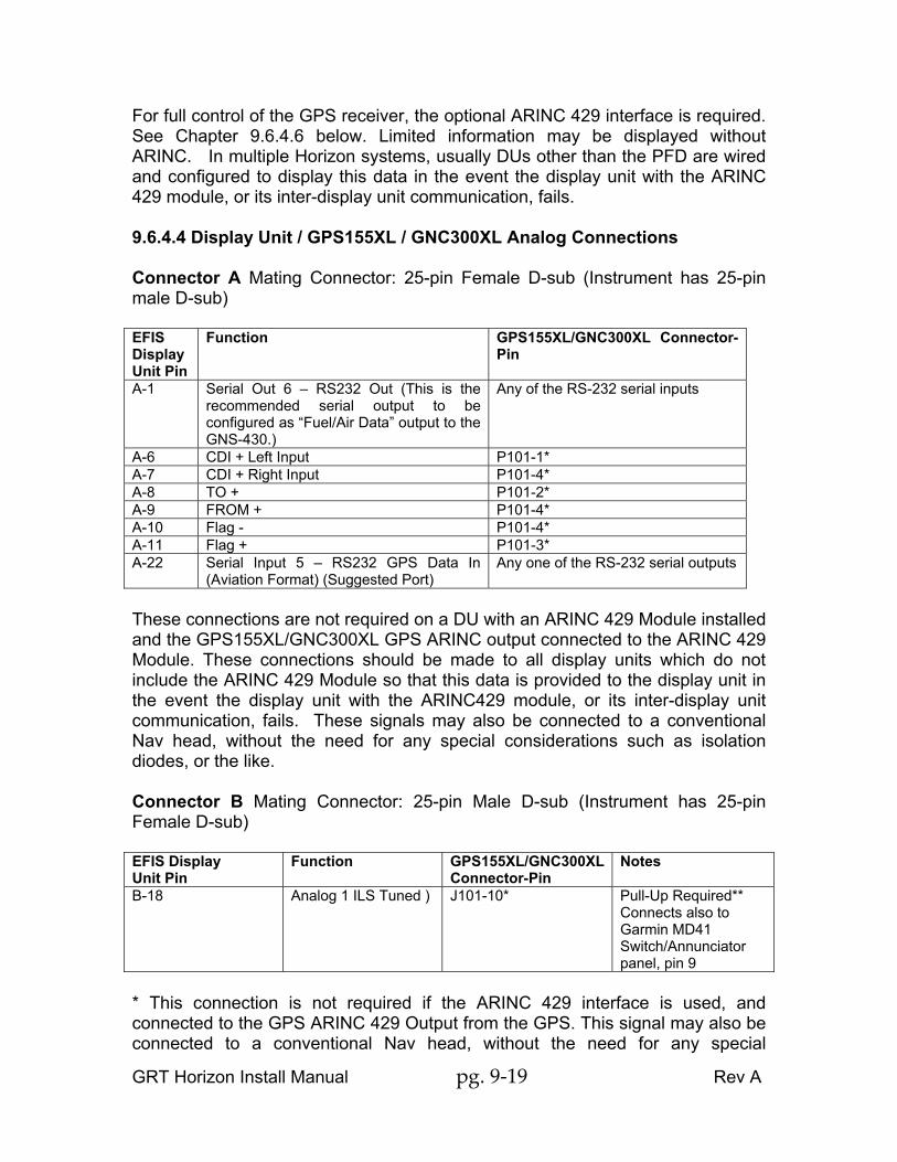
For full control of the GPS receiver, the optional ARINC 429 interface is required. See Chapter 9.6.4.6 below. Limited information may be displayed without ARINC. In multiple Horizon systems, usually DUs other than the PFD are wired and configured to display this data in the event the display unit with the ARINC 429 module, or its inter-display unit communication, fails. 9.6.4.4 Display Unit / GPS155XL / GNC300XL Analog Connections Connector A Mating Connector: 25-pin Female D-sub (Instrument has 25-pin male D-sub) EFIS Display Unit Pin
Function GPS155XL/GNC300XL Connector-Pin
A-1 Serial Out 6 – RS232 Out (This is the recommended serial output to be configured as “Fuel/Air Data” output to the GNS-430.)
Any of the RS-232 serial inputs
A-6 CDI + Left Input P101-1* A-7 CDI + Right Input P101-4* A-8 TO + P101-2* A-9 FROM + P101-4* A-10 Flag - P101-4* A-11 Flag + P101-3* A-22 Serial Input 5 – RS232 GPS Data In
(Aviation Format) (Suggested Port) Any one of the RS-232 serial outputs
These connections are not required on a DU with an ARINC 429 Module installed and the GPS155XL/GNC300XL GPS ARINC output connected to the ARINC 429 Module. These connections should be made to all display units which do not include the ARINC 429 Module so that this data is provided to the display unit in the event the display unit with the ARINC429 module, or its inter-display unit communication, fails. These signals may also be connected to a conventional Nav head, without the need for any special considerations such as isolation diodes, or the like. Connector B Mating Connector: 25-pin Male D-sub (Instrument has 25-pin Female D-sub) EFIS Display Unit Pin
Function GPS155XL/GNC300XL Connector-Pin
Notes
B-18 Analog 1 ILS Tuned ) J101-10* Pull-Up Required** Connects also to Garmin MD41 Switch/Annunciator panel, pin 9
* This connection is not required if the ARINC 429 interface is used, and connected to the GPS ARINC 429 Output from the GPS. This signal may also be connected to a conventional Nav head, without the need for any special

GRT Horizon Install Manual pg. 9-20 Rev A
considerations such as isolation diodes, or the like. ** Pull-Up required indicates a pull-up resistor is required. If this input is also connected to another system, such as a Nav head, the pull-up resistor is not required as long as this other system is installed. If this signal is not shared with other systems, a 10k ohm resistor, connected with one lead to aircraft 12V power, and the other lead “tee-d” into this connection is required. 9.6.4.5 Configuring the Display Unit for GPS155XL/GNC300XL Analog Input The display unit must be configured according to the following table to enable it to read the above analog signal. Set Menu Page Setting Value General Setup Analog 1 Function ILS Tuned General Setup Discrete 1 Active Voltage Low 9.6.4.6 Display Unit to GPS155XL/GNC300XL ARINC 429 Connections (GPS) At the time of this writing it is believed that ARINC 429 connections to the GPS are required or GNC300XL will error out. The benefits of using the ARINC 429 interface are as follows:
• CDI scaling information is provided directly by the GPS. Without this scaling information, the EFIS attempts to duplicate the scaling based flight plan data.
• Selected Course Data is provided to the GPS from the EFIS. This allows the CDI analog output of the GPS to operate correctly when waypoint sequencing is in the "HOLD" state.
• Magnetic Heading information is provided to the GPS. The following connections allow the EFIS and GPS155XL/GNC300XL to share information via the ARINC interface. ARINC 429 Adapter Pin
Function GPS155XL/GNC300XL Pin
GPS155XL/GNC300XL Function
C-3 (or C-1)* GPS Input J101-16 ARINC 429 A - GPS Output
C-4 (or C-2)* GPS Input J101-15 ARINC 429 B - GPS Output
C-5 EFIS Output May also connect to other devices, such as an autopilot
J101-32 ARINC 429 A Channel 1 EFIS Input.
C-9 EFIS Output May also connect to other devices, such as an autopilot
J101-33 ARINC 429 B - Channel 1 EFIS Input.

GRT Horizon Install Manual pg. 9-21 Rev A
* C-3, C-4 must be used as a pair, or C-1,C-2 must be used as a pair. 9.6.4.7 Configuring the Display Unit for ARINC Data Input Set Menu Page Setting Value General Setup ARINC Module Connected Yes General Setup ARINC Receive Rate* Low General Setup ARINC GPS Inputs* GPS1 (or GPS 2 if this display
unit is connected to number 2 GPS155XL/GNC300XL)
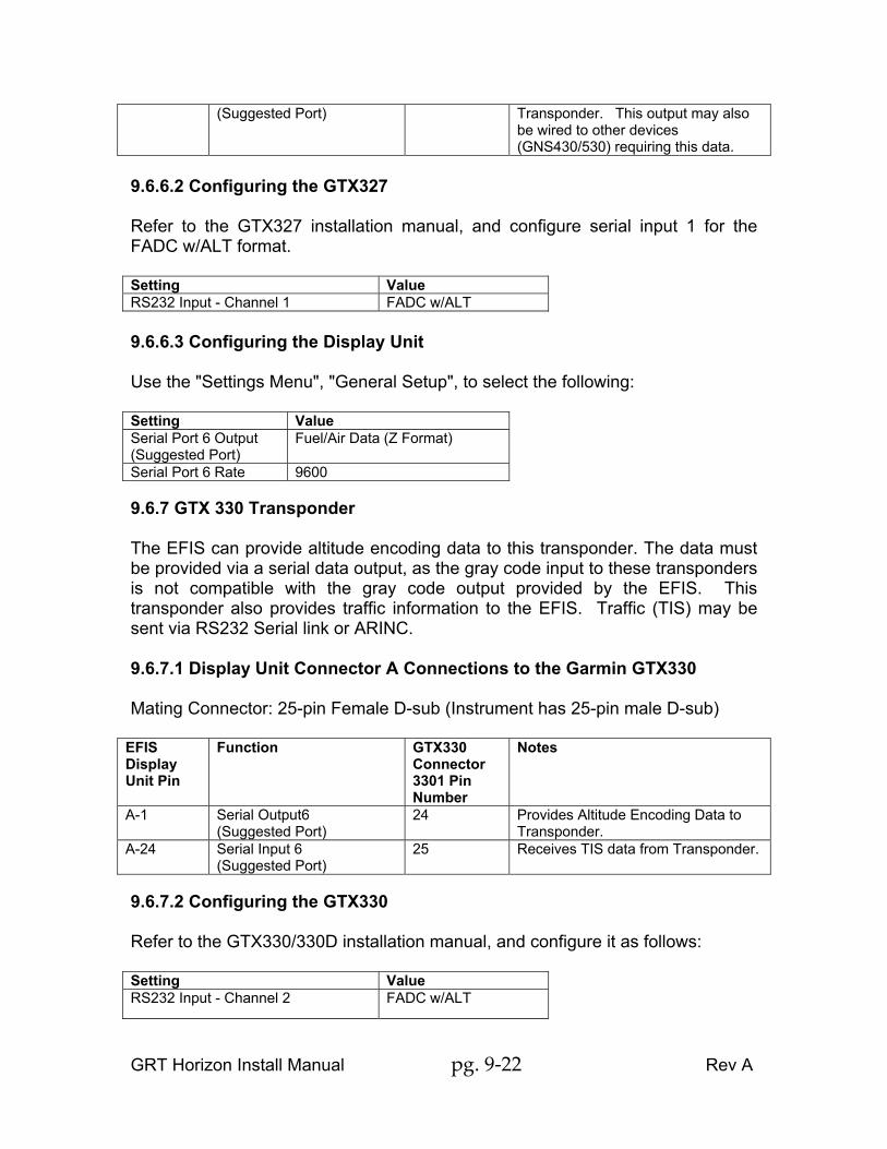
The display unit must be configured for "LOW" speed ARINC data. Note that since both ARINC input channels must be configured for the same rate, and since traffic data provided by the GNX330 is high speed, it is not possible to connect this GPS and the GTX330 transponder into the same ARINC 429 interface. 9.6.4.8 Configuring the GPS155XL/GNC300XL The GPS must be configured with its ARINC 429 output as "Collins PL2 EFS" or "King EFS 40/50". 9.6.5 Altitude Encoder Horizon WS & HS DUs have Gray code encoding outputs for transponders that require this format. These outputs are provided on connector B. Each output (such as A1, A2, A4, etc.) from the display unit connects to the corresponding input (A1, A2, A4, etc.) of the transponder. Gray code outputs are not available on Horizon HX. Encoding data must be sent using RS232 encoding information as described in the next paragraph. Most transponders accept RS232 serial data as described next. 9.6.6 GTX327 Transponder The EFIS can provide altitude encoding data to this transponder. The data must be provided via a serial data output, as the gray code input to these transponders is not compatible with the gray code output provided by the EFIS. 9.6.6.1 Display Unit Connector A Connections to the Garmin GTX327 Mating Connector: 25-pin Female D-sub (Instrument has 25-pin male D-sub)
EFIS Display Unit Pin
Function GTX327 Connector 3271 Pin Number
Notes
A-1 Serial Output 6 19 Provides Altitude Encoding Data to
GRT Horizon Install Manual pg. 9-22 Rev A
(Suggested Port) Transponder. This output may also be wired to other devices (GNS430/530) requiring this data.
9.6.6.2 Configuring the GTX327 Refer to the GTX327 installation manual, and configure serial input 1 for the FADC w/ALT format. Setting Value RS232 Input - Channel 1 FADC w/ALT 9.6.6.3 Configuring the Display Unit Use the "Settings Menu", "General Setup", to select the following: Setting Value Serial Port 6 Output (Suggested Port)
Fuel/Air Data (Z Format)
Serial Port 6 Rate 9600 9.6.7 GTX 330 Transponder The EFIS can provide altitude encoding data to this transponder. The data must be provided via a serial data output, as the gray code input to these transponders is not compatible with the gray code output provided by the EFIS. This transponder also provides traffic information to the EFIS. Traffic (TIS) may be sent via RS232 Serial link or ARINC. 9.6.7.1 Display Unit Connector A Connections to the Garmin GTX330 Mating Connector: 25-pin Female D-sub (Instrument has 25-pin male D-sub)
EFIS Display Unit Pin
Function GTX330 Connector 3301 Pin Number
Notes
A-1 Serial Output6 (Suggested Port)
24 Provides Altitude Encoding Data to Transponder.
A-24 Serial Input 6 (Suggested Port)
25 Receives TIS data from Transponder.
9.6.7.2 Configuring the GTX330 Refer to the GTX330/330D installation manual, and configure it as follows: Setting Value RS232 Input - Channel 2 FADC w/ALT

GRT Horizon Install Manual pg. 9-23 Rev A
RS232 Output - Channel 2 Remote + TIS
9.6.7.3 Configuring the Display Unit Use the "Settings Menu", "General Setup", to select the following: Setting Value Serial Port 6 In (Suggested Port)
Garmin TIS
Serial Port 6 Output (Suggested Port)
Fuel/Air Data (Z Format)
Serial Port 6 Rate 9600 9.6.7.4 ARINC Alternatively, TIS information may be transmitted via ARINC interface. 9.6.7.4.1 Connections with ARINC GTX330 Connector P3301 Pin Number
Function EFIS Pin Notes
30 Traffic Out ARINC C1 or (C3)*
ARINC Traffic
28 Traffic Out ARINC C2 or (C4)*
ARINC Traffic
24 Fuel/Air Data In A1 EFIS Serial 6 Out (Suggested Port) 25** Traffic Out A24 EFIS Serial 6 In (Suggested Port) * C-3, C-4 must be used as a pair, or C-1, C-2 must be used as a pair ** If no ARINC input available on EFIS, use Serial connection. 9.6.7.4.2 Configuring the Display Unit Use the "Settings Menu", "General Setup", to select the following: Setting Value Serial Port 6 In**(Suggested Port) Garmin TIS Serial Port 6 Output (Suggested Port)
Fuel/Air Data (Z Format)
Serial Port 6 Rate 9600 ARINC Module Connected Yes ARINC Receive Rate High ARINC In 1 Function GTX330 Traffic ** If no ARINC input available on EFIS, use Serial connection. 9.6.8 Other GPS (GPSMAP496, Lowrance etc)

GRT Horizon Install Manual pg. 9-24 Rev A
The EFIS can accept and display GPS data including flight plans. Most panel mount GPS supply data in GPS Aviation / MapCom format. Most hand held GPS (GPSMAP496 etc) supply data in NMEA 0183 format. 9.6.8.1 Display Unit Connector A Connections to other GPS EFIS Display Unit Pin
Function Other GPS Connection
Notes
A-22 Serial Port 5 IN (Suggested Port)
Varies RS232 Serial Data OUT
Use RS232 Serial Out from Other GPS
9.6.8.2 Configuring Other GPS Configure Other GPS for data out in either Aviation Format or NMEA 0183 format. 9.6.8.3 Configuring the Display Unit Use the "Settings Menu", "General Setup", to select the following: Setting Value Serial Port 5 Input (Suggested Port)
GPS1 Aviation /MapCom or NMEA 0183
Serial Port 5 Rate 9600 GPS1 Flight Plan Source
External
9.6.9 SL30/SL40 Nav/Com or Com 9.6.9.1 Display of Navigation Data from the SL30 The EFIS provides an HSI and other functions that display and use the VOR bearing data provided by the SL30 Nav/Com radio. Localizer and glide slope deviation data is also displayed on the EFIS from this radio. This data is transmitted to the EFIS display unit via an RS-232 output from the Nav radio. While the RS-232 connection is the preferred method for communicating this data to the EFIS, the SL30’s analog outputs for glideslope and localizer may also be connected to the EFIS. If both the RS-232 serial data connection and analog connections are made, the EFIS will use the RS-232 data. 9.6.9.2 Radio Tuning and Loading of Pre-Sets in the SL30/SL40 The EFIS has the ability to load the SL30 and SL40 with frequency pre-sets to allow convenient selection of these frequencies from the front panel controls of

GRT Horizon Install Manual pg. 9-25 Rev A
the radio. For the SL30, the EFIS can also tune the navigation radio. This data is transmitted to the radio via an RS-232 output from the EFIS display unit. 9.6.9.3 Multi-Display Unit Considerations Although the data from the SL30 may be communicated to other display units via the inter-display unit serial data connections, allowing this data to appear on all display units, it is preferable to connect the serial data output from the SL30 to each display unit. Connecting the serial output from the SL30 to each display unit in multiple display unit systems, allows the SL30 data to be displayed in the event one display unit is not functional. The serial ports within the display unit provide minimal loading of the serial data signals, allowing the one serial data output from the SL30 to be connected to multiple display units. Only one serial data output to the SL30/SL40 may be provided. If the display unit which provides this (tuning) data to the SL30/SL40 was not operational, the SL30/SL40 would be tuned by its front panel controls. 9.6.9.4 Display Unit Connector A Connections Mating Connector: 25-pin Female D-sub (Instrument has 25-pin male D-sub)
EFIS Display Unit Pin
Function SL30/SL40 Notes
A-2 Serial Output 1 from Display Unit to SL30/SL40 (Suggested Port)
Pin 4 of 37-pin connector-SL30 Pin 10 of 15-pin connector-SL40
Only 1 display unit may provide this connection.
A-20 Serial Input 1 from SL30 (Suggested Port)
Pin 5 of 37-pin connector
This output from the SL30 may be connected to multiple display units.
9.6.9.5 Configuring the Display Unit Using the general setup menu, set the display unit to which the above connections are made to 9600 baud. For the serial data output, select “SL30/SL40 Output”. For the serial input, select “SL30/SL40 Input”. 9.6.10 Autopilot The Horizon may send steering commands to an autopilot via RS232 Serial communications. These steering commands are GPS Nav format and provide Lateral steering only. Some advanced autopilots can accept GPSS and GPSV

GRT Horizon Install Manual pg. 9-26 Rev A
steering commands from the Horizon via ARINC and may provide both Lateral and Vertical steering. 9.6.10.1 Serial Interface Display Unit Connector A Connections
EFIS Display Unit Pin
Function Autopilot Connection
Notes
A-5 Serial Output 4 - Autopilot NEMA or Aviation (Suggested Port)
GPS Serial Data Input
Output from the EFIS emulates Aviation or NMEA 0813 format data to control the autopilot.
Optional Dual Serial Inputs to the Autopilot To allow coupling the autopilot to the GPS in the event the display unit that normally controls the autopilot is not functional, a switch may be installed. This switch is wired so that it selects either the EFIS autopilot output, or the GPS serial data output. This switch should remain in the "EFIS" position, unless the display unit that provides the autopilot output is not functional. When the switch is in the "GPS" position, the autopilot will follow the GPS flight plan only, and will not respond to EFIS autopilots mode selections, such as HDG or others. The switch needs to be a single pole, two position device. The common pin will be wired to the autopilot serial input and the other switch connections are one to the EFIS serial out port and one to the GPS receiver serial out port. Configuring the Autopilot Make the following setting on the autopilot. Refer to the autopilot installation manual for additional information. Setting Value RS232 Serial Input Baud Rate 4800 or as necessary to match
EFIS autopilot serial port baud rate.
9.6.10.2 ARINC Interface ARINC Connections For autopilots that accept ARINC 429 inputs for GPS steering, both the serial port autopilot connection (above), and the ARINC 429 connection are required.
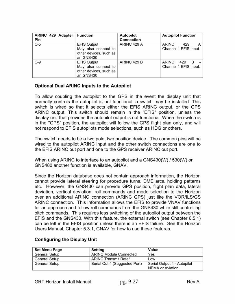
GRT Horizon Install Manual pg. 9-27 Rev A
ARINC 429 Adapter Pin
Function Autopilot Connection
Autopilot Function
C-5 EFIS Output May also connect to other devices, such as an GNS430
ARINC 429 A ARINC 429 A Channel 1 EFIS Input.
C-9 EFIS Output May also connect to other devices, such as an GNS430
ARINC 429 B ARINC 429 B - Channel 1 EFIS Input.
Optional Dual ARINC Inputs to the Autopilot To allow coupling the autopilot to the GPS in the event the display unit that normally controls the autopilot is not functional, a switch may be installed. This switch is wired so that it selects either the EFIS ARINC output, or the GPS ARINC output. This switch should remain in the "EFIS" position, unless the display unit that provides the autopilot output is not functional. When the switch is in the "GPS" position, the autopilot will follow the GPS flight plan only, and will not respond to EFIS autopilots mode selections, such as HDG or others. The switch needs to be a two pole, two position device. The common pins will be wired to the autopilot ARINC input and the other switch connections are one to the EFIS ARINC out port and one to the GPS receiver ARINC out port. When using ARINC to interface to an autopilot and a GNS430(W) / 530(W) or GNS480 another function is available, GNAV. Since the Horizon database does not contain approach information, the Horizon cannot provide lateral steering for procedure turns, DME arcs, holding patterns etc. However, the GNS430 can provide GPS position, flight plan data, lateral deviation, vertical deviation, roll commands and mode selection to the Horizon over an additional ARINC connection (ARINC GPS) just like the VOR/ILS/GS ARINC connection. This information allows the EFIS to provide VNAV functions for an approach and follow roll commands from the GNS430 while still controlling pitch commands. This requires less switching of the autopilot output between the EFIS and the GNS430. With this feature, the external switch (see Chapter 6.5.1) can be left in the EFIS position unless there is an EFIS failure. See the Horizon Users Manual, Chapter 5.3.1, GNAV for how to use these features. Configuring the Display Unit Set Menu Page Setting Value General Setup ARINC Module Connected Yes General Setup ARINC Transmit Rate* Low General Setup Serial Out 4 (Suggested Port) Serial Output 4 - Autopilot
NEMA or Aviation

GRT Horizon Install Manual pg. 9-28 Rev A
Configuring the Autopilot Setting Setting ARINC 439 A In Autopilot ARINC 429 B In Autopilot RS232 Baud Rate To match Horizon Output GNAV ARINC Connections ARINC 429 Adapter Pin
Function GNS430 Pin GNS430 Function
C-1 GPS Input J4001-46 ARINC 429 A - GPS Output May also connect to other devices, such as an autopilot
C-2 GPS Input J4001-47 ARINC 429 B – GPS Output May also connect to other devices, such as an autopilot
C-5 EFIS Output May also connect to other devices, such as an autopilot
J4001-48** ARINC IN 1A (J4001-50 ARINC IN 2A)
ARINC 429 A Channel 1 EFIS Input..
C-9 EFIS Output May also connect to other devices, such as an autopilot
J4001-49** ARINC IN 1B (J4001-51 ARINC IN 2B)
ARINC 429 B - Channel 1EFIS Input..
Configuring the Display Unit for GNAV ARINC Data In The display unit must be configured according to the following table to enable it to read the above ARINC signals: Set Menu Page Setting Value General Setup ARINC Receive Rate* To match GNS430 rate General Setup ARINC GPS Inputs* GPS1 (or GPS 2 if this display
unit is connected to number 2 GNS430/530)
Configuring the GNS430(W) / GNS530(W) or GNS480 for GNAV Refer to the GNS430 installation manual, and configure serial input 1 for the FADC w/ALT format, and serial output 2 for “GPS” format. Setting Value RS232 Input - Channel used for fuel/air data input from display unit.
Shadin-Fadc (Fadc only for GNS480)
RS232 Output - Channel Used for GPS Output Aviation

GRT Horizon Install Manual pg. 9-29 Rev A
to display unit. ARINC CONFG OUT DATA GAMA 429 ARINC CONFG SPEED Match VOR/LOC/GS output ARINC CONFG VNAV Enable labels 9.6.11 Zaon Traffic Zaon Collision Avoidance System requires only a Serial Port In connection to GRT Horizon. The data may either be Zaon format at 57600 baud or TIS Traffic format at 9600 baud. The later may be preferable since it does not tie up an entire Serial Port. The higher baud rate may deliver better performance since the data transmission rate is higher. High Speed Connection (57600 baud) EFIS Display EFIS Pin Zaon Pin Function Serial Port In Available Serial Port See Manual Profile 2 Configuration EFIS Display Function Zaon Function Serial Port In Zaon Traffic Serial Out Profile 2 Traffic Serial Port Rate 57600 Low Speed Connection (9600 baud) EFIS Display EFIS Pin Zaon Pin Function Serial Port In Available Serial Port See Manual Garmin Configuration EFIS Display Function Zaon Function Serial Port In Garmin GTX330 Serial Out Garmin Serial Port Rate 9600 9.6.12 CO Guardian Certain CO Guardian CO detectors have provisions for connection to MFD via RS232 Serial communication. Both a Serial Port In and a Serial Port Out connection to GRT Horizon is required since acknowledging the alarm sends a reset message to the detector. Connection EFIS Display EFIS Pin CO Guardian Pin Function Serial Port In Available Serial Port See Manual Serial Port Out Available Serial Port See Manual Configuration EFIS Display Function CO Guardian Function

GRT Horizon Install Manual pg. 9-30 Rev A
Serial Port In Co Guardian Serial Out CO Alarm Serial Port Rate 9600

GRT Horizon Install Manual pg. 10-1 Rev A
Chapter 10 : MOUNTING DIAGRAMS Please refer to www.grtavionics.com Support, Documents for up to date mounting information.

GRT Horizon Install Manual pg. 11-1 Rev A
Chapter 11 CONNECTOR DESCRIPTIONS Please refer to www.grtavionics.com Support, Documents for up to date connector descriptions.

GRT Horizon Install Manual pg. 12-1 Rev A
Chapter 12 INTERCONNECT DIAGRAMS Please refer to www.grtavionics.com, Support, Documents for up to date interconnect diagrams. Many find it useful to use the Interconnect Diagrams, the Cable Descriptions and Connector Definitions from the website and the information in this document to construct a spreadsheet defining all the interconnections for their particular aircraft and installed equipment. A sample spreadsheet is:
Unit Pin No
Name Use Format Baud TO/FROM Pin No Name
MFD 1
A-22 Serial 5 In
GPS Data
GPS Aviation
9600 GNS430 P4001-56
Serial 1 Out
Group each the Serial Port together, ie
Unit Pin No
Name Use Format Baud TO/FROM Pin No Name
Serial 1 In
Serial 1 Out
Serial 2 In
Etc Serial
6 Out
Then you can easily assign Serial ports keeping in mind that baud rate must the same for In and Out on each port. Note that Serial Port assignments shown in GRT documents are suggested only. Any Serial Port may be assigned any function with exceptions only being those connected to internal ARINC or GPS and the requirement of high speed ports for XM Weather. Use a similar spreadsheet to assign Analog inputs. Note that Analog Input assignments shown in GRT documents are suggested only. Add other connections to the spreadsheet such as power, OAT etc so that you end up with a comprehensive document that fully describes your aircraft.

GRT Horizon Install Manual pg. 13-1 Rev A
Chapter 13 MAGNETOMETER INSTALLATION Please refer to www.grtavionics.com Support, Documents for up to date magnetometer installation information.