horizon series basic transport stretcher model 402emb
TRANSCRIPT

Operating Manual
HauSteD® patient HanDling SySteMS, llC
Hausted® Horizon SeriesBasic transport Stretcher Model: 402eMBV1 01.11 076514

WARNING - COPYING PROHIBITEDthis manual is protected by Federal Copyright law, which provides for damages of up to uSD $20000, as well as criminal fines and imprisonment, for unauthorized copying.

i 076514
this manual contains important information on proper use and maintenance of the Hausted® Basic trans-port Stretcher. all personnel involved in the use and maintenance of this equipment must carefully review and comply with the warnings, cautions and instruc-tions contained in this manual. these instructions are important to protect the health and safety of person-nel operating a Hausted Basic transport Stretcher and should be retained in a conveniently accessible area for quick reference.
instructions for uncrating and connecting utilities, as well as equipment drawings, have been furnished. if missing, contact Hausted for replacement copies, giving the serial number and model numbers of the unit.
Hausted carries a complete line of accessories for use with this stretcher. a Hausted representative will gladly review these with you.
indications for use
the Hausted Basic transport Stretcher is intended for use in patient treatment, transport and recovery.
Service information
a thorough preventive maintenance program is essential to safe and proper unit operation. this manual contains maintenance schedules and procedures which should be followed for satisfactory equipment performance.
you are encouraged to contact Hausted concerning our comprehensive annual Maintenance agreements. under the terms of these agreements, preventive maintenance, adjustments, and replacement of worn parts are done
on a scheduled basis to assure equipment performance at peak capability and to help avoid untimely or costly interruptions. Hausted maintains a global staff of well equipped, factory-trained technicians to provide this service, as well as expert repair services. please contact your Hausted representative for details.
advisory
a listing of the safety precautions to be observed when operating and servicing this equipment can be found in Section 1 of this manual. Do not operate or service the equipment until you have become familiar with this information.
any alteration of this equipment not authorized or performed by Hausted engineering Service which could affect its operation, will void the warranty, could violate national, state, and local regulations, and could jeopardize your insurance coverage.
a wOrD FrOM HauSteD
©2011 Hausted® patient Handling Systems llC. all rights reserved printed in u.S.a.

ii 076514
EC Authorized RepresentativeCepartner4u BV eSDOOrnlaan 13 3951DB Maarn the netherlands +31(0)6 516 536 26
Manufactured by: Hausted® patient Handling Systems, llC 2511 Midpark road Montgomery, al 36109
334.215.5151 Main 877.706.5151 toll Free 334.215.5150 Fax
www.Hausted.com
equipment not suitable for use in the presence of a flammable anesthetic mixture with air or oxygen or nitrous oxide.
the base language of this document is engliSH. any translations must be made
from the base language document.

iii 076514
1 listing of warnings and Cautions ................................................................................................................1-12 uncrating instructions ..........................................................................................................................................2-13 Operating instructions ..........................................................................................................................................3-1 3.1 Stretcher Specifications .............................................................................................................................................3-1
3.2 Stretcher Features, warnings – Cautions and proper Operation .................................................................3-2
3.3 Braking and Steering Operation .............................................................................................................................3-4
3.3.1 applying the Brakes ................................................................................................................................................3-4
3.3.2 releasing the Brakes ...............................................................................................................................................3-4
3.3.3 applying the Steering lock/Fifth wheel ...........................................................................................................3-4
3.3.4 releasing the Steering lock/Fifth wheel .........................................................................................................3-4
3.4 Fowler Backrest Operation .......................................................................................................................................3-5
3.4.1 raising the Backrest ................................................................................................................................................3-5
3.4.2 lowering the Backrest ............................................................................................................................................3-5
3.5 retracto rail Operation ..............................................................................................................................................3-6
3.5.1 raising the rail .........................................................................................................................................................3-6
3.5.2 placing the rail at Half Height ............................................................................................................................3-6
3.5.3 lowering the rail ......................................................................................................................................................3-6
3.6 permanently Mounted iV rod Operation .............................................................................................................3-7
3.6.1 putting i.V. rod in up position ..............................................................................................................................3-7
3.6.2 extending i.V. rod ....................................................................................................................................................3-7
3.6.3 retracting i.V. rod .....................................................................................................................................................3-7
4 troubleshooting guide .........................................................................................................................................4-1 4.1 theory of Operation ....................................................................................................................................................4-1
4.1.1 Caster Braking System ............................................................................................................................................4-1
4.1.2 Center track Steering (if equipped) ...................................................................................................................4-1
4.1.3 retracto rail ..............................................................................................................................................................4-1
4.1.4 pneumatic Fowler Backrest ..................................................................................................................................4-1
4.2 Operator trouble Shooting guide .........................................................................................................................4-2
4.3 Service troubleshooting (For Service technicians) .........................................................................................4-3
5 recommended preventive Maintenance ................................................................................................5-1 5.1 recommended Cleaning instructions ...................................................................................................................5-1
5.2 Service technicians reference Chart .....................................................................................................................5-3
5.3 Caster Braking System Maintenance .....................................................................................................................5-4
taBle OF COntentS
iv 076514
5.3.1 adjusting the Caster Brakes .................................................................................................................................5-4
5.3.2 adjusting the Caster Steer-lock ..........................................................................................................................5-4
5.3.3 removing/replacing Casters ................................................................................................................................5-4
5.4 Fowler Backrest and retracto rail Maintenance ..............................................................................................5-5
5.4.1 adjusting the gas Spring .......................................................................................................................................5-5
5.4.2 removing/replacing the gas Spring ...............................................................................................................5-5
5.4.3 removing/replacing the rail ..............................................................................................................................5-6
5.4.4 removing/replacing the rail latch .................................................................................................................5-6
6 recommended Optional accessories ........................................................................................................6-17 recommended replacement parts ............................................................................................................. 7-18 warranty ...........................................................................................................................................................................8-1
taBle OF COntentS


1-1 076514
liSting OF warningS anD CautiOnS 1
the following is a listing of the safety precautions which must be observed when operating and servicing this equipment.
warningS indicate the potential for danger to personnel, and CautiOnS indicate the potential for damage to equipment. these precautions are repeated (in whole or in part), where applicable, throughout the manual.
warning–laCeratiOn HaZarD:
l when cutting bands, always use a tool specifically designed for that purpose. this will help to avoid personal injuries frequently incurred when bands are cut and tension released.
warningS – perSOnal inJury:
l Do not sit on end – tipping may occur.
l Be sure i.V. rod is inserted completely into socket up to the arrow before applying any load.
See Section 3 for the following warnings:
warningS – CautiOnS anD prOper OperatiOn:
l the stretchers have a warning label located near the head end stating: Maximum patient weight 226 Kilograms (500 lbs).
l patient entry, egress and transfer should always be done with the caster braking system locked.
l the caster braking system should always be locked when patient is not in transport.
l the caster braking system should always be locked and patient side rails up when patient is left unattended.
l always ensure that the side rail is locked before leaving patient unattended.


2-1 076514
unCrating inStruCtiOnS 2
l iMpOrtant - repOrt any SHipping DaMage iMMeDiately: inform shipper of any damages - leave carton intact. leave the equipment in the receiving area until inspection is complete.
l CautiOn - pOSSiBle eQuipMent DaMage: this crate contains fragile expensive medical equipment. uncrate and handle carefully.
if after uncrating the equipment you find any damage (no matter how slight), show it to your supervisor.
l warning - perSOnal inJury HaZarD: when cutting bands, always use tool specifically designed for that purpose. this will help avoid personal injuries frequently incurred when bands are cut and tension is released.
iMpOrtant: Follow each step in the order shown in these instructions.
unpaCKing inStruCtiOnS:
your Hausted equipment has been carefully packed at our manufacturing plant to ensure safe shipment to your medical facility. there are several procedures you must follow to put your new equipment in service. these procedures only take a few minutes to complete and are required to ensure proper operation of the equipment.
1. Cut the two bands around the shipping carton.
2. remove the top half of the carton and cut one side of the bottom half.
3. remove the equipment from the carton.
4. Check to see if all features of the equipment work properly. if all the features work, advance to step 5. if any of the features of the equipment do not work properly, call Hausted for service at: 877.706.5151.
5. Clean the equipment using mild detergent to remove any dirt accumulated during shipment, and place the equipment into service.


3-1 076514
Operating inStruCtiOnS 33.1 StretCHer SpeCiFiCatiOnS
l warning–perSOnal inJury: Maximum patient weight 226 Kilograms (500 lbs)
nOte: all dimensions are specified in inches. all dimension are ±.375 inches.
Hausted reserves the right to change specifications without notice.
3-2 076514
Operating inStruCtiOnS 33.2 FeatureS, warningS anD prOper OperatiOn
l warningS–CautiOnS anD prOper OperatiOn: Do not sit on end – tipping may occur.
a. the stretchers have a warning label located at the foot end stating: Maximum patient weight 226 kilograms (500 lbs).
B. patient entry, egress and transfer should always be done with the breaks locked.
C. the caster braking system should always be locked when patient is not in transport.
D. the caster braking system should always be locked and patient side rails up when patient is left unattended.
e. always ensure that the side rail is locked before leaving patient unattended.

3-3 076514
Operating inStruCtiOnS 33.2 FeatureS, warningS anD prOper OperatiOn
3 pOSitiOn SiDe railS See warnings D and e
See warnings B, C and D
See warnings D and e
3-4 076514
Operating inStruCtiOnS 33.3 BreaKing anD Steering OperatiOn
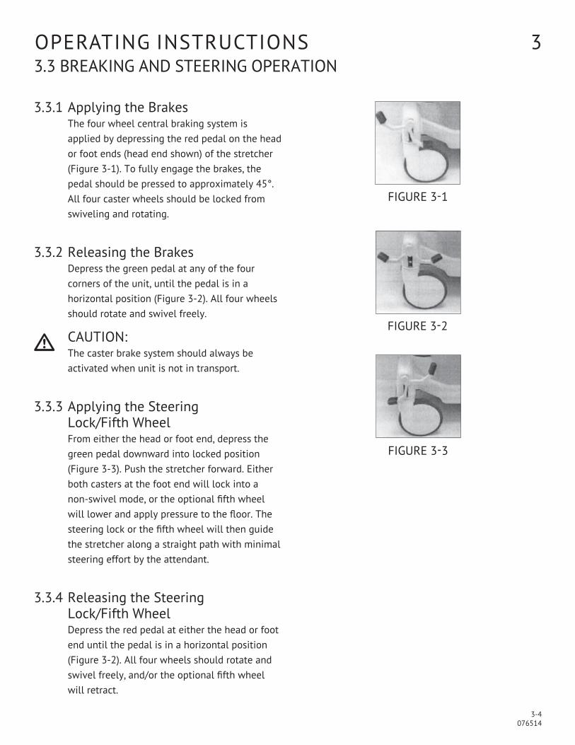
3.3.1 applying the Brakes the four wheel central braking system is applied by depressing the red pedal on the head or foot ends (head end shown) of the stretcher (Figure 3-1). to fully engage the brakes, the pedal should be pressed to approximately 45°. all four caster wheels should be locked from swiveling and rotating.
3.3.2 releasing the BrakesDepress the green pedal at any of the four corners of the unit, until the pedal is in a horizontal position (Figure 3-2). all four wheels should rotate and swivel freely.
l CautiOn: the caster brake system should always be activated when unit is not in transport.
3.3.3 applying the Steering
lock/Fifth wheelFrom either the head or foot end, depress the green pedal downward into locked position (Figure 3-3). push the stretcher forward. either both casters at the foot end will lock into a non-swivel mode, or the optional fifth wheel will lower and apply pressure to the floor. the steering lock or the fifth wheel will then guide the stretcher along a straight path with minimal steering effort by the attendant.
3.3.4 releasing the Steering
lock/Fifth wheelDepress the red pedal at either the head or foot end until the pedal is in a horizontal position (Figure 3-2). all four wheels should rotate and swivel freely, and/or the optional fifth wheel will retract.
Figure 3-1
Figure 3-2
Figure 3-3
3-5 076514
Operating inStruCtiOnS 33.4 FOwler BaCKreSt OperatiOn
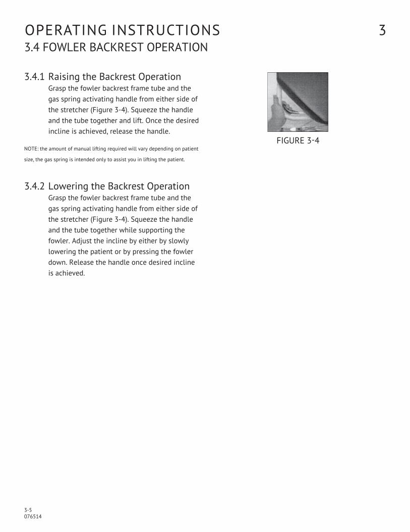
3.4.1 raising the Backrest Operation grasp the fowler backrest frame tube and the gas spring activating handle from either side of the stretcher (Figure 3-4). Squeeze the handle and the tube together and lift. Once the desired incline is achieved, release the handle.
nOte: the amount of manual lifting required will vary depending on patient
size, the gas spring is intended only to assist you in lifting the patient.
3.4.2 lowering the Backrest Operationgrasp the fowler backrest frame tube and the gas spring activating handle from either side of the stretcher (Figure 3-4). Squeeze the handle and the tube together while supporting the fowler. adjust the incline by either by slowly lowering the patient or by pressing the fowler down. release the handle once desired incline is achieved.
Figure 3-4

3-6 076514
Operating inStruCtiOnS 33.5 retraCtO rail OperatiOn
l CautiOn: always be sure rail is locked in the full and upright position before leaving the patient unattended.
3.5.1 raising the railgrasp the rail top cap in the middle of the rail (Figure 3-5) and lift.
3.5.2 placing the rail at Half Height
grasp the rail, lift up on the red trigger under the litter top (Figure 3-6) while lowering the rail. when rail starts to move down release trigger. lower rail until it locks into half height position.
3.5.3 lowering the rail
grasp the rail. lift up on the red trigger under the top (Figure 3-6), while lowering the rail. Hold up on the rail trigger until the rail is all the way down.
Figure 3-5
Figure 3-6

3-7 076514
Operating inStruCtiOnS 33.6 perManently MOunteD iV rOD OperatiOn
l warning – perSOnal inJury HaZarD: the caster brake system should always be activated when unit is not in transport.
3.6.1 putting i.V. rod in up position grasp i.V. rod and rotate upward until it stops (Figure 3-7). push down on i.V. rod until it slides firmly into the socket.
3.6.2 extending i.V. rodlift up on top of i.V. rod (Figure 3-8) until desired height is achieved.
3.6.3 applying the Steering
lock/Fifth wheelpress button located in the plastic housing (Figure 3-9) and lower i.V. rod until desired height is achieved. release button to hold desired position. repeat process with second housing as required.
Figure 3-7
Figure 3-8
Figure 3-9


4-1 076514
trOuBleSHOOting guiDe 44.1 tHeOry OF OperatiOn
4.1.1 Caster Braking System the Hausted caster system utilizes a system known as “the Four wheel Brake and Steer System.” Four casters are used, two each Brake and Swivel and two each Brake and Steer. the Brake and Steer caster’s are located at the patients foot unless otherwise special ordered by the customer. the caster system can also be ordered with an optional Center Steering Caster (Center track Steering/ Fifth wheel - see below. the system was designed for ease of use and patient safety. a series of levers are positioned at the both ends of the base to activate. One step on the green pedal cap engages steering. the system is designed to initially start pushing the unit from the head end and on your next step, all in one motion, push down the steer side of the shift lever. this locks the steer caster(s) in the “trailing position.” if the unit is not initially pushed from the head end, it is possible for the steer caster(s) to lock 180 degrees opposite, causing a wobble. the red side of the lever engages the brake. push down on the red pedal pad and all four brakes are engaged. if the brakes are adjusted properly, with force you will be able to pull the tire past the brake shoe. if the brake is not adjusted to this specification, the unit will not stay in position, or the brake shoe will indent the tire causing a flat spot on the tire. when all the levers are level, the caster system is in neutral. all casters are in the swivel mode. this position is used to push the unit from the side position to another unit for patient transfer.
4.1.2 Center track Steering (if equipped)the Center track Steering (fifth wheel) System used on the Horizon, utilizes a center wheel that contacts the floor when the steering lock (green) pedal is activated. the wheel is mounted to a fork under the unit, that is spring loaded and held above the floor while in either the brake or in neutral positions. when the steer lock (green) pedal is pressed, arms that are connected to the hex rods, rotate a cam positioned above the fifth wheel fork. the cam is rotated, forcing the center wheel to apply pressure to the floor.
4.1.3 retracto rail
the rail is designed to have a down position where the legs cradle over each other within the bumper channel and main frame of the top. the half position may be used for patient treatment while still allowing some patient protection, and full upright position for patient transport mode and while patient is unattended.
4.1.4 pneumatic Fowler Backrest
the backrest uses a charged gas spring (pneumatic cylinder). Handles are located in the backrest that activate the cylinder. this cylinder assists the attending personnel for patient positioning.

4-2 076514
trOuBleSHOOting guiDe 44.2 OperatOr trOuBleSHOOting guiDe
Symptoms Cause resolutionCasters: • unit will not track straight down
hallway• unit slides when going around
corners• unit moves during treatment
• unit is not locked into the Steer/lock position or casters are dirty
• Steer lock caster(s) or fifth wheel are dirty
• unit is not locked into the Brake position or casters are dirty
• push green side of shift lever down. Clean debris from casters
• Clean steer caster tire or fifth wheel tire (if equipped)
• push red side of shift lever down. Clear debris from casters
Backrest:• Backrest raises on its own
without a patient or descends with a patient
• Backrest will not raise
• activation handle is stuck in the activated position
• activation handle is stuck in the released position
• Check for obstruction (pad, sheet) that would prevent handle from returning to the released position
• Check for obstruction that would prevent handle from activating
rails:• rail will not stay up• rail will not release
• rail latch is not locking properly• rail latch stuck and will not
release rail
• Check for obstruction at latch (pad, sheet)
• lift slightly on rail to prevent bind
nOte: Stretchers are to be serviced by qualified personnel only. if the resolutions listed above do not resolve the problem
Or if the problem you are experiencing is not listed above, contact Hausted for service.
For Hausted Service, please contact:Hausted patient Handling Systems at877.706.5151(please be sure to have stretcher model and serial number available.)
4-3 076514
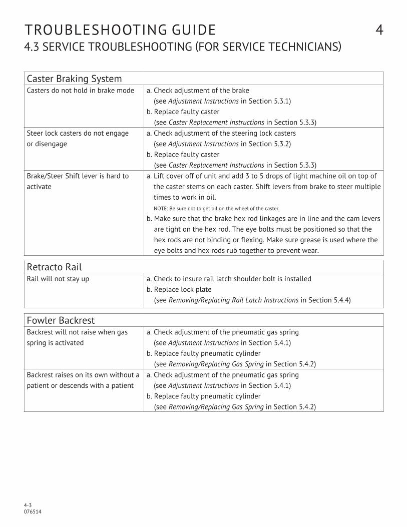
trOuBleSHOOting guiDe 44.3 SerViCe trOuBleSHOOting (FOr SerViCe teCHniCianS)
Caster Braking SystemCasters do not hold in brake mode a. Check adjustment of the brake
(see Adjustment Instructions in Section 5.3.1)b. replace faulty caster
(see Caster Replacement Instructions in Section 5.3.3)Steer lock casters do not engage or disengage
a. Check adjustment of the steering lock casters (see Adjustment Instructions in Section 5.3.2)
b. replace faulty caster (see Caster Replacement Instructions in Section 5.3.3)
Brake/Steer Shift lever is hard to activate
a. lift cover off of unit and add 3 to 5 drops of light machine oil on top of the caster stems on each caster. Shift levers from brake to steer multiple times to work in oil. nOte: Be sure not to get oil on the wheel of the caster.
b. Make sure that the brake hex rod linkages are in line and the cam levers are tight on the hex rod. the eye bolts must be positioned so that the hex rods are not binding or flexing. Make sure grease is used where the eye bolts and hex rods rub together to prevent wear.
retracto railrail will not stay up a. Check to insure rail latch shoulder bolt is installed
b. replace lock plate (see Removing/Replacing Rail Latch Instructions in Section 5.4.4)
Fowler BackrestBackrest will not raise when gas spring is activated
a. Check adjustment of the pneumatic gas spring (see Adjustment Instructions in Section 5.4.1)
b. replace faulty pneumatic cylinder (see Removing/Replacing Gas Spring in Section 5.4.2)
Backrest raises on its own without a patient or descends with a patient
a. Check adjustment of the pneumatic gas spring (see Adjustment Instructions in Section 5.4.1)
b. replace faulty pneumatic cylinder (see Removing/Replacing Gas Spring in Section 5.4.2)


5-1 076514
reCOMMenDeD preVentiVe MaintenanCe 5
procedure Schedule Materiallubricate all moving and sliding parts and hinge points
3 Months lubricating oil, light-duty grease, wax stick lubricant or graphite lubricant.
l neVer luBriCate gaS Spring, SHaFtS linspect all fasteners to ensure proper fit, position and tightness (including nuts, bolts, etc.).
3 Months proper size wrench and screwdriver.
inspect all surfaces and remove any user developed sharp or burred areas. apply touch-up where required.
3 Months Metal File, proper color paint (specify color when ordering).

5-2 076514
For more detailed information, please contact:Hausted patient Handling Systems at877.706.5151
reCOMMenDeD preVentiVe MaintenanCe 55.1 reCOMMenDeD Cleaning inStruCtiOnS
Component Cleaning procedure Schedule Cleaning agent Special notespads wipe with damp cloth
to remove any foreign materials
after each use routine Hospital grade Disinfectants, Soap and water
• use only medium strength cleaners
• Do not steam clean or pressure wash
Stretcher wipe with damp cloth to remove any foreign materials
after each use routine hospital grade disinfectants, soap and water
lubricate pivot points after cleaning
accessories wipe with damp cloth to remove any foreign materials
after each use routine hospital grade disinfectants, soap and water
lubricate pivot points after cleaning
nOte: Steam cleaning and pressure washing of stretcher is not recommended and can void warranty.
l CautiOn – pOSSiBle eQuipMent DaMage HaZarD Steam cleaning and pressure washing of stretcher is not recommended and can void warranty.

5-3 076514
reCOMMenDeD preVentiVe MaintenanCe 5 5.2 SerViCe teCHniCianS reFerenCe CHart
1.0 preparation For preventive Maintenance 1.1 Discuss equipment with Operators ........................................................................................................each2.0 general inspection 2.1 Verify that all Fasteners are Secure. each
2.2 Check weld integrity - Frame, Columns, top assembly, accessories. ............................................each
2.3 Check For Scratches Or peeling On painted Surfaces. .....................................................................each
2.4 Check tabletop For any excessive Horizontal Or Vertical play. ....................................................each
3.0 Casters, Steering and Braking System 3.1 Check / Clean Caster wheels. ....................................................................................................................each
3.2 lubricate Caster Stems, eye Bolts, linkages, using 3-5 Drops Of Oil.
note: Be Sure not to get Oil On the wheel Of the Caster. ...........................................................a/r
3.3 replace Brake (red) and Steer (green) pedal pads. ..........................................................................a/r
3.4 Verify Operation Of Steer, neutral and Brake Functions. ................................................................each
3.5 Fifth wheel (if equipped) - Verify proper Operation in Brake (wheel Off Floor),
neutral (wheel Off Floor) and Steer (wheel On Floor) positions, .................................................each
4.0 patient Side rails 4.1 Check rail Fasteners. ...................................................................................................................................each
4.2 Verify that the rail locks in the upright and Half Height positions. .......................................each
5.0 Fowler Backrest 5.1 Check Fowler pivot pins. .............................................................................................................................each
5.2 Verify that pneumatic Fowlers Stay when Handles are released
and that Fowler is not Spongy. ...............................................................................................................each
6.0 accessories 6.1 Verify that all accessories are not Broken Or Damaged and Can Be Securely attached. ..each
7.0 Final testing 7.1 Secure all Covers and Shrouds. ................................................................................................................each
7.2 reinstall any pads and accessories that were removed. inspect pads For rips, tears, etc each
7.3 Check area to insure removal Of all Materials used During inspection. .................................each
7.4 notify Customer that pM inspection is Complete. ............................................................................each
Description Frequency

5-4 076514
reCOMMenDeD preVentatiVe MaintenanCe 55.3 CaSter BraKing SySteM MaintenanCe
5.3.1 adjusting the Caster BrakesSee Base assembly parts list in Section 7. tools required: Small straight bladed screwdriver
1. using the screwdriver, knock out the small plastic plug on the back of the caster (items 2 and/or 3). 2. place the braking system in the neutral position. 3. insert the screwdriver into the hole in the back of the caster created in step 1 and rotate the adjustment
screw clockwise to increase the brake tension and counter clockwise to decrease brake pressure. 4. with the brake properly adjusted, the brake should allow the tire to rotate with force. if the brake is over
adjusted, it will release with very little effort (Bumped under normal operating conditions). nOte: preventive maintenance – apply 3-5 drops of oil in top of stem.
nOte: Be sure not to get oil on the wheel of the caster.
5.3.2 adjusting the Caster Steer-lockSee Base assembly parts list in Section 7.
1. the steer lock casters on the 402 are not adjustable, if the steer lock function is not working properly, replace the faulty caster.
5.3.3 removing/replacing Casters
See Base assembly parts list in Section 7. 1. raise the plastic base cover (item 27) and tie to top with bungy cord. 2. place the braking system in brake mode. 3. remove either the starlock cap (item 17) or the brake pedal assembly (item 12 or 13) next to
the caster being removed. 4. loosen the lock collar (item 15) on the hex rod, opposite the caster being removed, and loosen brake
rod cam (item 10) set screw. 5. with a blunt end punch and hammer, knock the hex rod (item 11) out of the
top of the caster being removed. 6. using a screwdriver, bend the tabs away from the caster bolt lock plates (item 4)
then remove the two caster bolts (item 5). 7. Drop caster from frame (item 1). 8. locate the new caster (red top brake, green top steer). with the 7/16” hex allen wrench, lock new caster
in brake mode, taking note of the position for the hex relative to the hex rod. 9. reinstall caster by reversing steps 1-6. 10. using instant adhesive, glue rubber grommet (item 22) on top of new caster.
5-5 076514
reCOMMenDeD preVentatiVe MaintenanCe 55.4 FOwler BaCKreSt anD retraCtO rail MaintenanCe
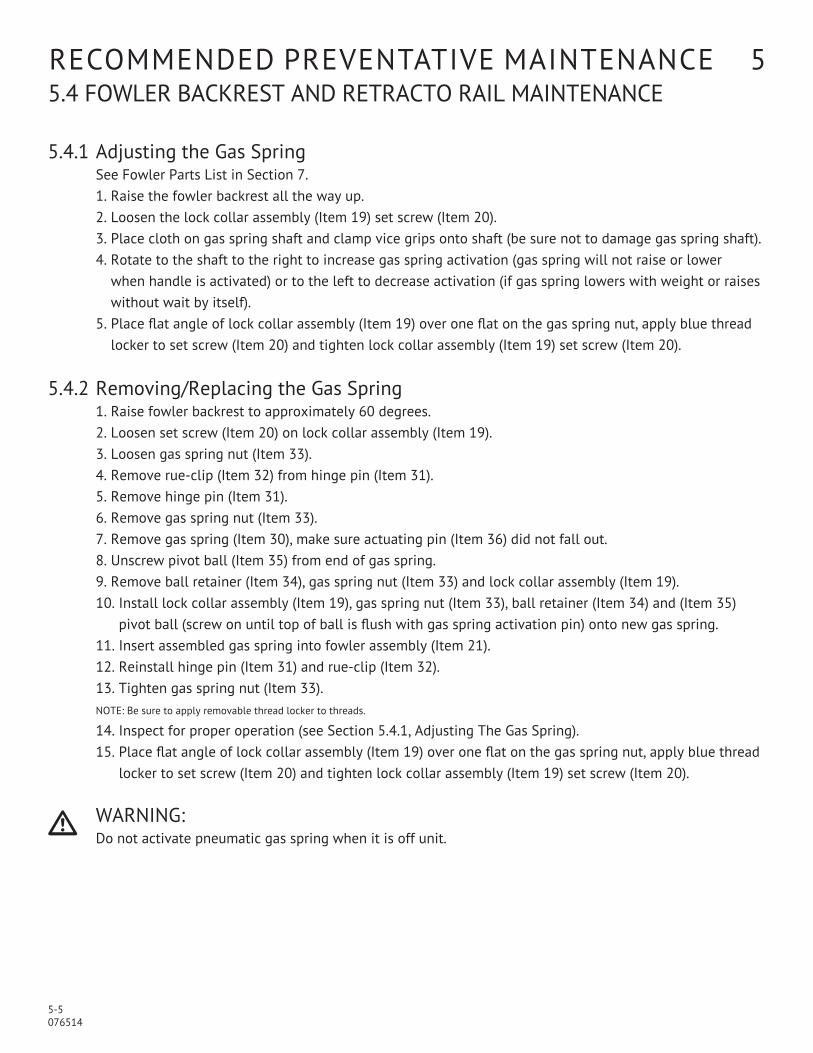
5.4.1 adjusting the gas SpringSee Fowler parts list in Section 7.
1. raise the fowler backrest all the way up. 2. loosen the lock collar assembly (item 19) set screw (item 20). 3. place cloth on gas spring shaft and clamp vice grips onto shaft (be sure not to damage gas spring shaft). 4. rotate to the shaft to the right to increase gas spring activation (gas spring will not raise or lower
when handle is activated) or to the left to decrease activation (if gas spring lowers with weight or raises without wait by itself).
5. place flat angle of lock collar assembly (item 19) over one flat on the gas spring nut, apply blue thread locker to set screw (item 20) and tighten lock collar assembly (item 19) set screw (item 20).
5.4.2 removing/replacing the gas Spring 1. raise fowler backrest to approximately 60 degrees. 2. loosen set screw (item 20) on lock collar assembly (item 19). 3. loosen gas spring nut (item 33). 4. remove rue-clip (item 32) from hinge pin (item 31). 5. remove hinge pin (item 31). 6. remove gas spring nut (item 33). 7. remove gas spring (item 30), make sure actuating pin (item 36) did not fall out. 8. unscrew pivot ball (item 35) from end of gas spring. 9. remove ball retainer (item 34), gas spring nut (item 33) and lock collar assembly (item 19). 10. install lock collar assembly (item 19), gas spring nut (item 33), ball retainer (item 34) and (item 35)
pivot ball (screw on until top of ball is flush with gas spring activation pin) onto new gas spring. 11. insert assembled gas spring into fowler assembly (item 21). 12. reinstall hinge pin (item 31) and rue-clip (item 32). 13. tighten gas spring nut (item 33). nOte: Be sure to apply removable thread locker to threads.
14. inspect for proper operation (see Section 5.4.1, adjusting the gas Spring). 15. place flat angle of lock collar assembly (item 19) over one flat on the gas spring nut, apply blue thread
locker to set screw (item 20) and tighten lock collar assembly (item 19) set screw (item 20).
l warning: Do not activate pneumatic gas spring when it is off unit.
5-6 076514
reCOMMenDeD preVentatiVe MaintenanCe 55.4 FOwler BaCKreSt anD retraCtO rail MaintenanCe
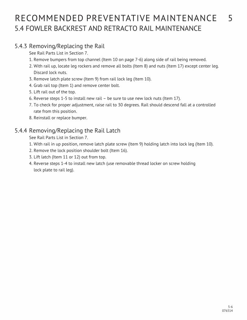
5.4.3 removing/replacing the railSee rail parts list in Section 7.
1. remove bumpers from top channel (item 10 on page 7-6) along side of rail being removed. 2. with rail up, locate leg rockers and remove all bolts (item 8) and nuts (item 17) except center leg.
Discard lock nuts. 3. remove latch plate screw (item 9) from rail lock leg (item 10). 4. grab rail top (item 1) and remove center bolt. 5. lift rail out of the top. 6. reverse steps 1-5 to install new rail – be sure to use new lock nuts (item 17). 7. to check for proper adjustment, raise rail to 30 degrees. rail should descend fall at a controlled
rate from this position. 8. reinstall or replace bumper. 5.4.4 removing/replacing the rail latch
See rail parts list in Section 7. 1. with rail in up position, remove latch plate screw (item 9) holding latch into lock leg (item 10). 2. remove the lock position shoulder bolt (item 16). 3. lift latch (item 11 or 12) out from top. 4. reverse steps 1-4 to install new latch (use removable thread locker on screw holding
lock plate to rail leg).

6-1 076514
reCOMMenDeD OptiOnal aCCeSSOrieS 6
pads and Mattressesnumber Description031654-60 Mattress, 2" (50.8 mm) x 24.5" (622.3 mm) x 76" (1930.4 mm) conductive foam
031655-60 Mattress, 3" (76.2 mm) x 24.5" (622.3 mm) x 76" (1930.4 mm) conductive foam
061893-60 pressurCare Mattress, 4" (101.6 mm) x 24.5" (622.3 mm) x 76" (1930.4 mm) conductive foam
068921-60 enhanced pressurCare Mattress, 5" (127 mm) x 24.5" (622.3 mm) x 76" (1930.4 mm) covered with Fusion ii material, hunter green
069200-00 “Slick” patient transfer system, 4" (101.6 mm) x 24.5" (622.3 mm) x 76" (1930.4 mm) 2 parts, 1 transfer mattress and 3" base mattress
patient restnumber Description000012-00 restraint strap with buckle (Qty. 1)
000014-00 restraint strap with Velcro (Qty. 1)
Head and Foot Boardsnumber Description00006B-00 Head and foot board - stationary
00Cr6B-00 Head and foot board - stationary with chart rack
00007B-00 extension head and foot board
00Cr7B-00 extension head and foot board - with chart rack
Monitor Shelvesnumber Description00n4500-00 Monitor shelf, removable, folding
065765-00 Head/foot board monitor shelf w/chart rack
068836-00 extension footboard/monitor shelf w/chart rack
133170-00 under fowler utility tray (stainless steel)
i.V. poles and i.V. accessoriesnumber Description000018-00 telescoping iV pole, 3 section, removable, stainless steel –
27" (685.8 mm) to 54" (1371.6 mm)
128770-00 telescoping iV pole, 3 section, removable, stainless steel – 27" (685.8 mm) to 54" (1371.6 mm) permanently attached with cable
000e17-00 Fixed iV pole, removable, stainless steel – 42" (61066.8 mm)
066rr0-00 telescoping iV pole, 3 section, permanently attached at head end – 21" (533.4 mm) to 45" (1143 mm) – 1" (25.4 mm) dia. lower tube
133380-00 telescoping iV pole, 3 section, permanently attached at foot end – 21" (533.4 mm) to 45" (1143 mm) – 1" (25.4 mm) dia. lower tube
065897-00 Mobile i.V. stand attachment

6-2 076514
l it is recommended that only Hausted approved accessories be used with this device. to order accessories, or for more detailed information on accessories, please contact Hausted at: 1.877.706.5151
Miscellaneousnumber Description076334-00 armboard w/2" (50.8 mm) pad and surgical mounting adapter
065366-00 universal patient tray
075656-00 Self storing push handles
076533-00 Center track steering system (Fifth wheel)
069257-00 paper roll holder
128450-00 Vertical 02 tank holder
128840-00 Drainage bag hooks (pair)
131934-00 Burgundy color bumpers and pin striping
131935-00 teal color bumpers and pin striping
131936-00 plum color bumpers and pin striping
reCOMMenDeD OptiOnal aCCeSSOrieS 6
7-1 076514
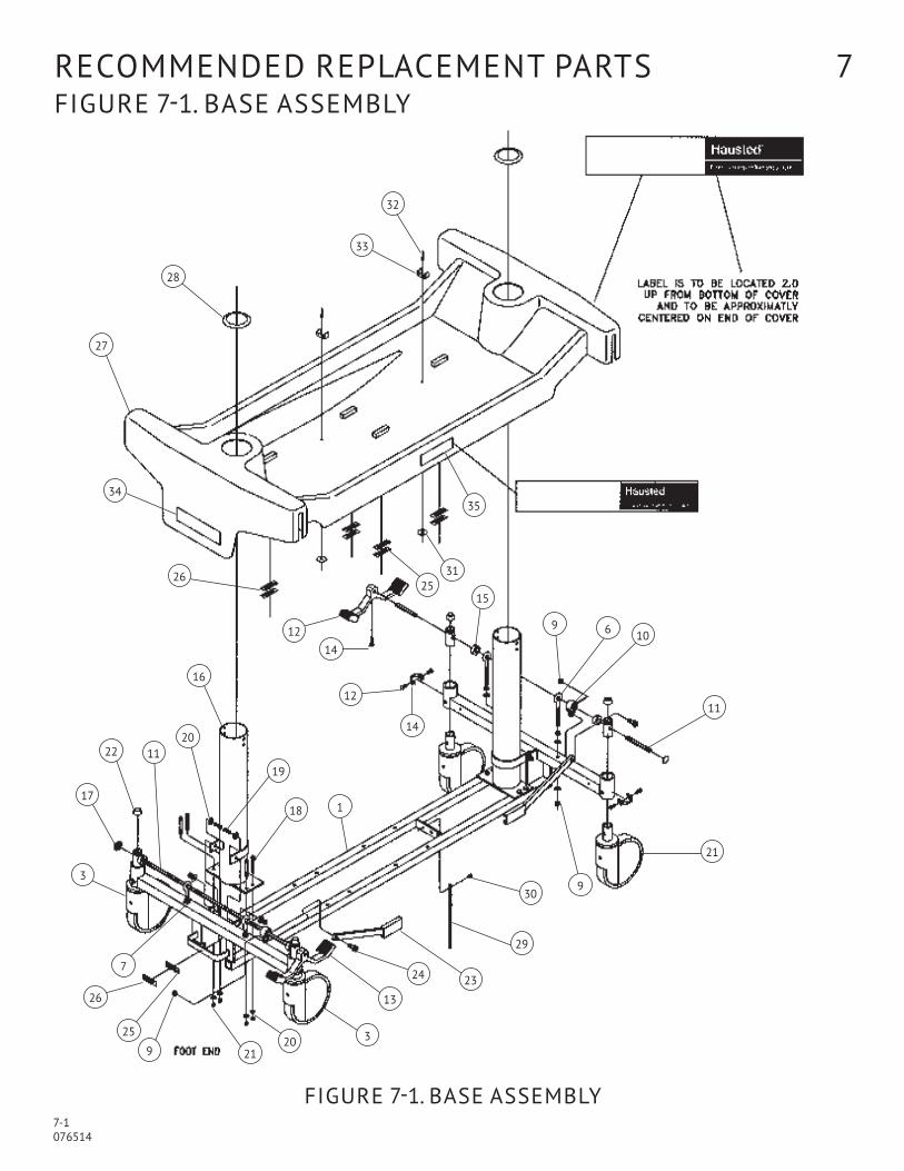
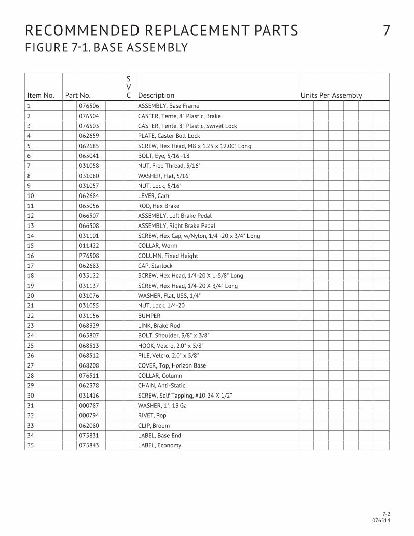
reCOMMenDeD replaCeMent partS 7 Figure 7-1. BaSe aSSeMBly
Figure 7-1. BaSe aSSeMBly
32
33
35
28
27
3125
15
26
34
12
14
12
14
9 6 10
11
9
21
30
29
1
2324
13
32021
18
9
25
26
7
3
17
22 1120
19
16
7-2 076514
reCOMMenDeD replaCeMent partS 7 Figure 7-1. BaSe aSSeMBly
item no. part no.
S V C Description units per assembly
1 076506 aSSeMBly, Base Frame
2 076504 CaSter, tente, 8" plastic, Brake
3 076503 CaSter, tente, 8" plastic, Swivel lock
4 062659 plate, Caster Bolt lock
5 062685 SCrew, Hex Head, M8 x 1.25 x 12.00" long
6 065041 BOlt, eye, 5/16 -18
7 031058 nut, Free thread, 5/16"
8 031080 waSHer, Flat, 5/16"
9 031057 nut, lock, 5/16"
10 062684 leVer, Cam
11 065056 rOD, Hex Brake
12 066507 aSSeMBly, left Brake pedal
13 066508 aSSeMBly, right Brake pedal
14 031101 SCrew, Hex Cap, w/nylon, 1/4 -20 x 3/4" long
15 011422 COllar, worm
16 p76508 COluMn, Fixed Height
17 062683 Cap, Starlock
18 035122 SCrew, Hex Head, 1/4-20 X 1-5/8" long
19 031137 SCrew, Hex Head, 1/4-20 X 3/4" long
20 031076 waSHer, Flat, uSS, 1/4"
21 031055 nut, lock, 1/4-20
22 031156 BuMper
23 068329 linK, Brake rod
24 065807 BOlt, Shoulder, 3/8" x 3/8"
25 068513 HOOK, Velcro, 2.0" x 5/8"
26 068512 pile, Velcro, 2.0" x 5/8"
27 068208 COVer, top, Horizon Base
28 076511 COllar, Column
29 062378 CHain, anti-Static
30 031416 SCrew, Self tapping, #10-24 X 1/2”
31 000787 waSHer, 1", 13 ga
32 000794 riVet, pop
33 062080 Clip, Broom
34 075831 laBel, Base end
35 075843 laBel, economy

7-3 076514
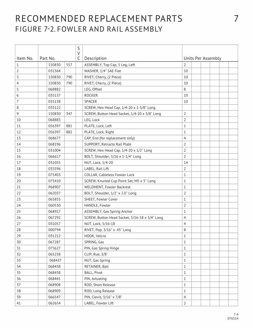
reCOMMenDeD replaCeMent partS 7 Figure 7-2. FOwler anD rail aSSeMBly
Figure 7-2. FOwler anD rail aSSeMBly
14
2
1517
12
2632
1
31
25
27
18
5
7
8
20
18
303 1
4
9
24
40
39
40
22
23
38
2136
35
3433
19
37
13
10
13
graSp HanDle tO Operate BaCKreSt
Both Sides
7-4 076514
reCOMMenDeD replaCeMent partS 7 Figure 7-2. FOwler anD rail aSSeMBly
item no. part no.
S V C Description units per assembly
1 150830 557 aSSeMBly, top Cap, 5 leg, left 2
2 031364 waSHer, 1/4" Sae Flat 10
3 150830 790 riVet, Cherry, (2 piece) 10
4 150830 790 riVet, Cherry, (2 piece) 10
5 068882 leg, Offset 8
6 035137 rOCKer 10
7 035138 SpaCer 10
8 035122 SCrew, Hex Head Cap, 1/4-20 x 1-5/8" long
9 150830 347 SCrew, Button Head Socket, 1/4-20 x 3/8" long 2
10 068883 leg, lock 2
11 056397 881 plate, lock, left 1
12 056397 882 plate, lock, right 1
13 068677 Cap, end (for replacement only) 4
14 068196 SuppOrt, retracto rail plate 2
15 031004 SCrew, Hex Head Cap, 1/4-20 x 1/2" long 2
16 066617 BOlt, Shoulder, 5/16 x 1-1/4" long 2
17 031055 nut, lock, 1/4-20 14
18 035596 laBel, rail lift 2
19 075403 COllar, Cableless Fowler lock 1
20 075410 SCrew, Knurled Cup point Set, M5 x 5" long 1
21 p68907 welDMent, Fowler Backrest 1
22 062037 BOlt, Shoulder, 1/2" x 2.0" long 2
23 065855 SHeet, Fowler Cover 1
24 060530 HanDle, Fowler 2
25 068917 aSSeMBly, gas Spring anchor 1
26 067292 SCrew, Button Head Socket, 5/16-18 x 3/4" long 4
27 031057 nut, lock, 5/16-18 4
28 000794 riVet, pop, 3/16" x .45" long 8
29 031212 HOOK, Velcro 1
30 067287 Spring, gas 1
31 075627 pin, gas Spring Hinge 1
32 065258 Clip, rue, 3/8" 1
33 068437 nut, gas Spring 1
34 068438 retainer, Ball 1
35 068438 Ball, pivot 1
36 068441 pin, artuating 1
37 068908 rOD, Short release 1
38 068909 rOD, long release 1
39 066547 pin, Clevis, 3/16" x 7/8" 4
41 062654 laBel, Fowler lift 2

7-5 076514
reCOMMenDeD replaCeMent partS 7 Figure 7-3. tOp aSSeMBly
Figure 7-3. tOp aSSeMBly
14
2
18
19
13
15
17
7
10
??
9
6
8
3
4
1
5
20
11
16
12
7
For Service Call 877.706.5151
L warning: MaXiMuM patient weigHt 227 KilOgraMS (500 lBS)L attentiOn: pOiDS MaXiMuM Du patient 227 KilOgraMMeS (500 liVreS)L aDVertenCia: peSO MÁXiMO Del paCiente 227 KilOgraMOS (500 liBraS)

7-6 076514
reCOMMenDeD replaCeMent partS 7 Figure 7-3. tOp aSSeMBly
item no. part no.
S V C Description units per assembly
1 075399 welDMent, top 1
2 065509 MOunting, Bracket Crosstube 4
3 075229 Clip, arrow nylon, 1/8" 4
4 031057 nut, lock, 5/16-18 8
5 075226 Cap, i.V. well top 4
6 067958 BuMper, Corner 4
7 061195 SCrew, Button Head Socket, 1/4-20 x 5/8" long 8
8 031455 nut, Channel 8
9 068154 eXtruSiOn, end Bumper, gray 2
13193M eXtruSiOn, end Bumper, Burgundy 2
13193n eXtruSiOn, end Bumper, teal 2
13193p eXtruSiOn, end Bumper, purple 2
10 067959 eXtruSiOn, Side Bumper, gray 2
067960 eXtruSiOn, Side Bumper, Burgundy 2
067961 eXtruSiOn, Side Bumper, teal 2
067964 eXtruSiOn, Side Bumper, purple 2
11 065057 pan, top Sheet 2
12 055213 riVet, 1/4" x 1/2" long 12
13 076505 CrOSStuBe, Fixed Height 2
14 031101 SCrew, Hex Head w/patch, 1/4-20 x 3/4" long 8
15 062073 plug, Crosstube 4
16 031312 HOOK, Velcro 1
17 031118 pin, Spring, 3/6" x 1.0" long 8
18 031457 laBel, Serial number 1
19 063022 laBel, Service 1
20 075490 laBel, Maximum patient weight 1
21 031655 60 paD, 3" (not Shown) 1
7-7 076514
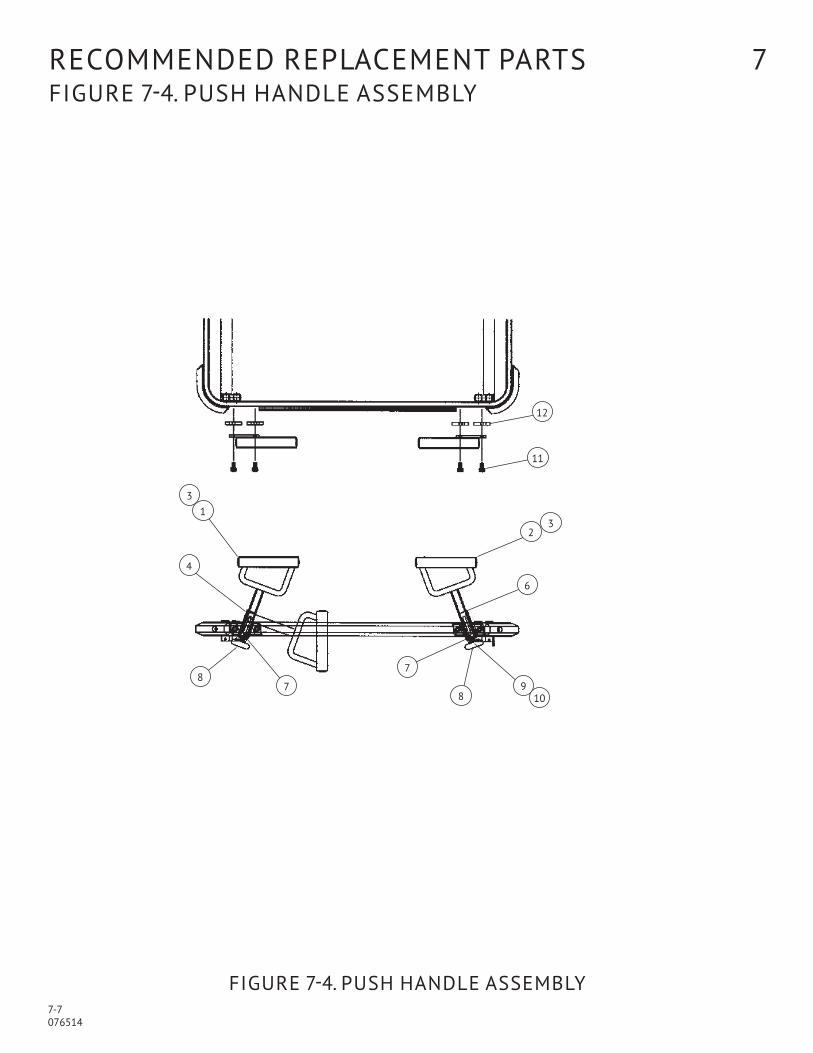
reCOMMenDeD replaCeMent partS 7 Figure 7-4. puSH HanDle aSSeMBly
Figure 7-4. puSH HanDle aSSeMBly
12
11
13
4
23
87
7
6
89
10

7-8 076514
reCOMMenDeD replaCeMent partS 7 Figure 7-4. puSH HanDle aSSeMBly
item no. part no.
S V C Description units per assembly
1 075631 aSSeMBly, push Handle “a” 1
2 075642 aSSeMBly, push Handle “B” 1
3 075637 welDMent, push Handle 1
4 075633 BraCKet, Hinge “a” 1
5 075634 BraCKet, Hinge “B” 1
6 031118 pin, Spring, 3/16" x 1" 1
7 075643 BuMper, 1-3/4" Dia. 1
8 031364 waSHer, Flat, 1/4" 2
9 031055 nut, lock, 1/4-20 1
10 075657 SCrew, Socket Head Cap, 5/16-18 x 1/2" long 4
11 066018 nut, Channel, 5/16-18 4
7-9 076514
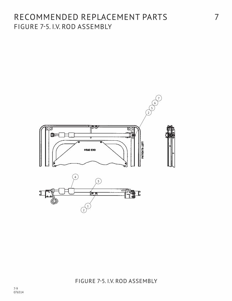
reCOMMenDeD replaCeMent partS 7 Figure 7-5. i.V. rOD aSSeMBly
Figure 7-5. i.V. rOD aSSeMBly
25
6
7
43
12

7-10 076514
reCOMMenDeD replaCeMent partS 7 Figure 7-5. i.V. rOD aSSeMBly
item no. part no.
S V C Description units per assembly
1 062038 SCrew, Button Head Cap, 1/4-20 x 5/8" long 2
2 031055 nut, lock, 1/4-20 7
3 075568 SuppOrt, Bracket i.V. rod 1
4 075545 aSSeMBly, trigger Style i.V. rod 1
5 031137 SCrew, Hex Head Cap, 1/4-20 x 3/4" long 2
6 031364 waSHer, Flat, 1/4" 2
7 030923 waSHer, lock, 3/8" 2
7-11 076514
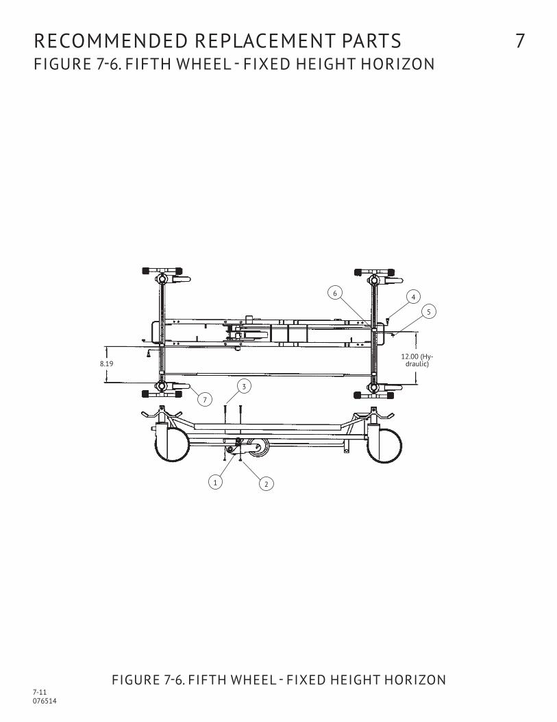
reCOMMenDeD replaCeMent partS 7 Figure 7-6. FiFtH wHeel - FiXeD HeigHt HOriZOn
Figure 7-6. FiFtH wHeel - FiXeD HeigHt HOriZOn
6 4
7
3
1 2
5
12.00 (Hy-draulic)8.19

7-12 076514
reCOMMenDeD replaCeMent partS 7 Figure 7-6. FiFtH wHeel - FiXeD HeigHt HOriZOn
item no. part no.
S V C Description units per assembly
1 075796 SuBaSSeMBly 1
2 031055 nut, lock, 1/4-20 4
3 031006 SCrew, Hex Head Cap, 1/42- x 1-1/2" long 4
4 065807 BOlt, Shoulder, 3/8" x 3/8" long 2
5 031057 nut, lock, 5/16" 2
6 062684 CaM 2
7 062672 CaSter, tente, Brake 1

7-13 076514
reCOMMenDeD replaCeMent partS 7 Figure 7-6. FiFtH wHeel – FiXeD HeigHt HOriZOn
Figure 7-6. FiFtH wHeel - FiXeD HeigHt HOriZOn
5
2319
17
20
4
14
1311
15
161
22
7
212
58
9
18
103
12
21
Spring & wheel Bracket Sub-assembly
Foot end
Section a-a
Section B-B
Set Screw location for item 12
Set Screw location for item 12
Set Screw location for item 13
Set Screw location for item 12
Set Screw location for item 13
a a
Flush
7-14 076514
reCOMMenDeD replaCeMent partS 7 Figure 7-6. FiFtH wHeel – FiXeD HeigHt HOriZOn
item no. part no.
S V C Description units per assembly
1 075775 welDMent, Mounting Bracket, left Hand 1
2 075771 Spring, torsion 1
3 011422 COllar 1
4 075776 welDMent, Mounting Bracket, right Hand 1
5 075780 rOD, pivot 1
6 075778 welDMent, upper Bracket 1
7 075793 Spring, urethane 1
8 075779 Spring, retainer 1
9 075772 BraCKet, wheel 1
10 069154 nut, Spoke 1
11 075781 rOD, Hex 1
12 062684 CaM 2
13 075782 CaM, auto track 1
14 067861 SCrew, Socket Set, 1/4-20 x 1/4" long 1
15 075794 BOlt, Shoulder, 1/4" x 3/8" long 1
16 075792 Bearing 1
17 075783 linK, long 1
18 075784 linK, Short 1
19 075785 wHeel, 5" 1
20 031334 SCrew, Hex Head Cap 1
21 031057 nut, lock, 5/16-18 3
22 065807 BOlt, shoulder, 3/8" x 3/8" long 2
23 035119 waSHer, nylon 1
7-15 076514
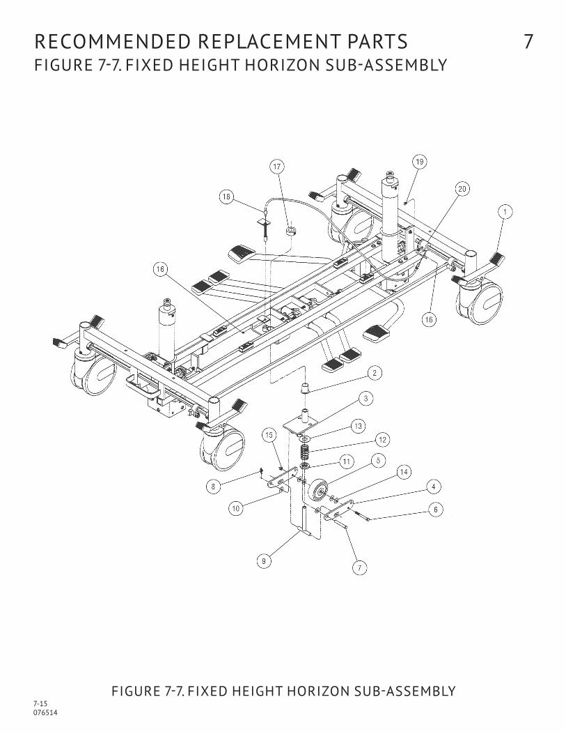
reCOMMenDeD replaCeMent partS 7 Figure 7-7. FiXeD HeigHt HOriZOn SuB-aSSeMBly
Figure 7-7. FiXeD HeigHt HOriZOn SuB-aSSeMBly

7-16 076514
reCOMMenDeD replaCeMent partS 7 Figure 7-7. FiXeD HeigHt HOriZOn SuB-aSSeMBly
item no. part no.
S V C Description units per assembly
069060 4160 FIFTH WHEEL CENTER TRACK ASSEMBLY, 3” X
068516 4160 FIFTH WHEEL CENTER TRACK ASSEMBLY, 4” X
1 p 150830 734 aSSeMBly, Horizon Base 1 1
2 051308 nyliner, Flange, 3/4” x 1-1/8” 1 1
3 068360 aSSeMBly, Swivel Bracket 1 1
4 068429 plate, 5th wheel Hinge plate 2 2
5 069061 wHeel, 3” 1 –
068415 wHeel, 4” – 1
6 069062 SCrew, Hex Head Cap, M6 x 60 mm long 1 1
7 058419 pin, Clevis, 5/16” x 2.0” long 1 1
8 068417 Clip, rue, 5/16 1 1
9 068540 aSSeMBly, Spring Stop 1 1
10 065688 waSHer, nylon, 5/16” 2 2
11 068416 SpaCer 1 1
12 068173 Spring, 5th wheel 1 1
13 031077 waSHer, Flat, 1/2” i.D. x 1.063” O.D. 1 1
14 031364 waSHer, 1/4” 4 4
15 069063 nut, lock, M6 1 1
16 062640 ring, retaining 2 2
17 068464 COllar, 3/4 1 1
18 p 056397 843 aSSeMBly, 5th wheel Cable 1 1
19 068544 SCrew, Button Head Socket, 1/4-20 x 3/8” long 1 1
20 069007 tuBe, large Cam 1 1

8-1 076514
warranty 8
we reserve the right to make changes at anytime in prices, materials, equipment, specifications, accessories and models, or to discontinue items at anytime consistent with the latest design trends or factors beyond our control.
liMiteD warranty
we warrant that our patient-handling and optional accessories equipment, with the exception of casters, pneumatic springs, pads, mat-
tresses and weighing systems and electric components, will be free from defects in workmanship, material and operation for a period of
five years from the date of delivery to the purchaser — provided such equipment has been properly installed and maintained and has not
been misused and abused. the determination of proper installation, maintenance and use shall rest solely with Hausted. exempt five year
warranty items include:
Casters 1 year warranty
pneumatic gas springs 1 year warranty
pads and mattresses 1 year warranty
patient weighing systems 1 year warranty
Optional accessories 1 year warranty
all electrical components 1 year warranty
if you claim that any defect has developed in the workmanship, material or operation of any equipment within the stated warranty periods,
and we confirm the existence of such defect resulting from other than normal wear and tear, we shall fulfill the warranty obligation by provid-
ing the necessary part(s) and labor during the first year of the warranty, for the repair or defect. the balance of the warranty period is limited
to replacement parts only. Such correction will be the sole remedy for the defect.
this statement constitutes our entire warranty with respect to the aforesaid equipment. we MaKe nO OtHer warranty Or repreSentatiOn, eitHer eXpreSSeD Or iMplieD, eXCept aS Set FOrtH Herein. tHere iS nO warranty OF MerCHantaBility anD tHere are nO warrantieS OF FitneSS FOr any partiCular purpOSe. in nO eVent SHall we Be liaBle HereunDer FOr inCiDental Or COnSeQuential DaMageS ariSing FrOM Or in any Manner relateD tO SaleS Or uSe OF any SuCH eQuipMent.
DaMageD MerCHanDiSe
iCC regulations require that claims for damaged merchandise must be made with the carrier within 15 days of receipt of merchandise. DaMageD CartOnS are tO Be put On HOlD until DOCuMentatiOn Can Be MaDe By a SurVey. nOtiFiCatiOn OF releaSe will Be Sent wHen SurVey iS COMplete. DO nOt aCCept DaMageD SHipMentS unleSS SuCH DaMage iS nOteD On tHe Bill OF laDing Or DeliV-ery DOCuMentS at tHe tiMe OF reCeipt. upon prompt notification, Hausted will file freight claim with the appropriate carrier for damage incurred. Claims will be limited in amount to actual replacement cost. in the event that information is not received by Hausted within the 15 day period following
delivery of merchandise, or the damage was not noted on the bill of lading or delivery documents at the time of receipt, the cus-tomer will be responsible for payment of the original invoice in full.
replacement parts will be shipped when acknowledgment of a filed freight claim is given to Hausted by the carrier.
Claims for any short shipment must be made within 30 days of invoice.
return autHOriZatiOn
Merchandise cannot be returned without specific written approval from the Hausted Customer Service Department (call 877.706.5151).
all telephone calls regarding merchandise returned must be made to Hausted within 7 calendar days of receipt of the merchandise.
an authorization number will be provided to you to return the merchandise. transporta-tion expense, plus a 15 percent restocking charge will be paid by the customer.
SpeCial, MODiFieD Or DiSCOntinueD iteMS are nOt SuBJeCt tO return.
©Copyright august 2010 by Hausted patient Handling Systems, llC
2511 Midpark road, Montgomery, al 36109
all rights reserved. printed in u.S.a.


2511 MiDparK rOaDMOntgOMery, al 36109
334.215.5151 MAIN877.706.5151 TOLL FREE334.215.5150 FAX
WWW.HAuSTED.COM
prOteCt yOur HauSteD eQuipMent witH COSt-eFFeCtiVe eXtenDeD SerViCe agreeMentS
the best way to prevent costly downtime due to equipment malfunction is with regularly scheduled maintenance performed by qualified technicians trained in the latest technology. Hausted offers annual maintenance agreements to give your capital equipment planned maintenance agreements that will help correct little problems before they become big ones. Hausted engineering Service combines the precise maintenance program and factory-trained technicians to assure you of maximum productivity.
Our Hausted service technicians thoroughly inspect, clean, adjust and provide all necessary maintenance to keep your equipment performing according to factory specifications, all at an established economical rate that you can plan for.