horizontal press manual - cleveland steel tool · pdf filehorizontal press manual 800-446-4402...
TRANSCRIPT

Horizontal PressManual
800-446-4402www.clevelandsteeltool.com
474 E. 105th St. • Cleveland, OH 44108
Serial #__________________________
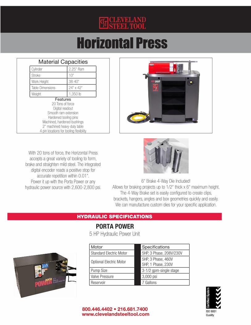
Horizontal Press
Features20 Tons of forceDigital readout
Smooth ram extensionHardened tooling pins
Machined, hardened bushings2" machined heavy-duty table
4 pin locations for tooling flexibility
Cylinder 2.25" Ram
Stroke 10"
Work Height 38-40"
Table Dimensions 24" x 42"
Weight 1,350 lb
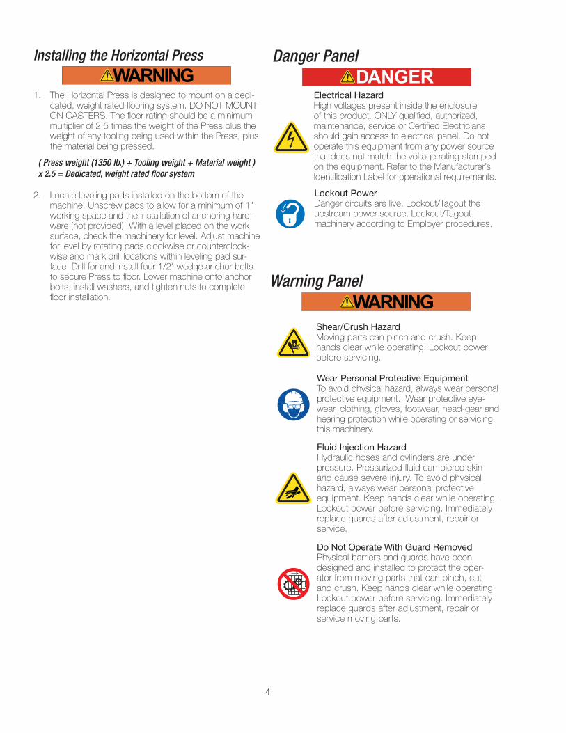
Motor SpecificationsStandard Electric Motor 5HP, 3 Phase, 208V/230V
Optional Electric Motor5HP, 3 Phase, 460V5HP, 1 Phase, 230V
Pump Size 3-1/2 gpm-single stageValve Pressure 3,000 psiReservoir 7 Gallons
5 HP Hydraulic Power Unit
With 20 tons of force, the Horizontal Press accepts a great variety of tooling to form,
brake and straighten mild steel. The integrated digital encoder reads a positive stop for
accurate repetition within 0.01". Power it up with the Porta Power or any
hydraulic power source with 2,600-2,800 psi.
HYDRAULIC SPECIFICATIONS
PORTA POWER
800.446.4402 • 216.681.7400 www.clevelandsteeltool.com
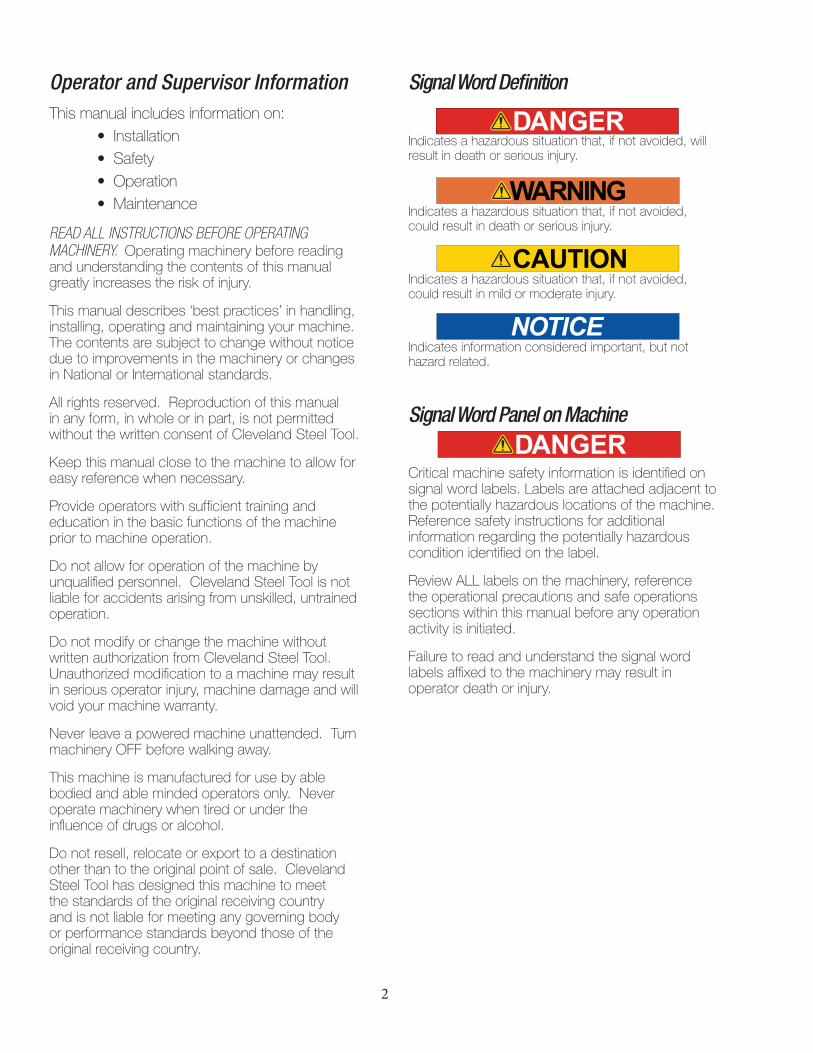
6" Brake 4-Way Die Included!Allows for braking projects up to 1/2" thick x 6" maximum height.
The 4-Way Brake set is easily configured to create clips,brackets, hangers, angles and box geometries quickly and easily. We can manufacture custom dies for your specific application.
Material Capacities

Table of Contents1 Company Profile, Warranty2 Operator and Supervisor Information, Signal Definitions3 Receiving/Unpacking/Moving3 Environmental Requirements4 Installation 4-5 Danger/Warning Panel, Maintenance6 Signal DiagramHYDRAULIC POWER SOURCES7 Hydraulic Accessory Tool, Porta PowerOPERATION8 Operations9 Operations Diagram10 Set Up11 Press OperationsTROUBLESHOOTING12 Horizontal Press Inoperable12 Rough Cylinder Operation


1
Company ProfileThe Cleveland Steel Tool Company offers a full line of high quality, low maintenance hydraulic ironworking machines, associated tooling and accessories that are used in the steel fabrication industry. With proper operation, care, and maintenance, your Cleveland Steel Tool Horizontal Press will provide years of safe, trouble-free service. Please take time to study this manual carefully to fully understand Horizontal Press safety procedures, set-up, operation, care, maintenance, troubleshooting and warranty coverage prior to putting the machine into production. Any questions not answered within this manual can be directed to The Cleveland Steel Tool Company.
474 E. 105th St.Cleveland, OH 44108800-446-4402 ph216-681-7009 [email protected]
Machine IdentificationYour Cleveland Steel Tool Horizontal Press has been serialized for quality control, product traceability and warranty enforcement. Please refer to the aluminum identification tag with the engraved serial number and electrical and power specifications when ordering parts or filing a warranty claim.
WarrantyThe Cleveland Steel Tool Company will, within one (1) year of date of purchase, replace F.O.B. the factory, any goods, excluding punches, dies, and/or blades, which are defective in materials and workmanship provided that the buyer returns the defective goods, freight prepaid, to the seller, which shall be the buyer’s sole and exclusive remedy for the defective goods. Hydraulic and electrical components are subject to their respective manufacturer’s warranties.
The Cleveland Steel Tool Company will, within thirty (30) days of date of purchase, replace F.O.B. the factory any punches, dies, and/or blades that prove to be defective in material and workmanship.
(Proof of purchase date required)
This warranty does not apply to machines and/or components which have been altered, changed or modified in any way, or subjected to abusive and abnormal use, inadequate maintenance and lubrication, or subjected to use beyond seller recommended capacities and specifications. THIS WARRANTY IS VOID IF YOU ATTEMPT REPAIRS YOURSELF. In no event shall seller be liable for labor costs expended on such goods or consequential damages. Seller shall not be liable to the purchaser or any other person for loss, downtime, or damage directly or indirectly arising from the use of the goods or from any other cause. No officer, employee, or agent of seller is authorized to make any oral representations or warranty of fitness or to waive any of the foregoing terms of sale and none shall be binding on seller.
2
Operator and Supervisor InformationThis manual includes information on: • Installation • Safety • Operation • Maintenance
READ ALL INSTRUCTIONS BEFORE OPERATING MACHINERY. Operating machinery before reading and understanding the contents of this manual greatly increases the risk of injury.
This manual describes ‘best practices’ in handling, installing, operating and maintaining your machine. The contents are subject to change without notice due to improvements in the machinery or changes in National or International standards.
All rights reserved. Reproduction of this manual in any form, in whole or in part, is not permitted without the written consent of Cleveland Steel Tool.
Keep this manual close to the machine to allow for easy reference when necessary.
Provide operators with sufficient training and education in the basic functions of the machine prior to machine operation.
Do not allow for operation of the machine by unqualified personnel. Cleveland Steel Tool is not liable for accidents arising from unskilled, untrained operation.
Do not modify or change the machine without written authorization from Cleveland Steel Tool. Unauthorized modification to a machine may result in serious operator injury, machine damage and will void your machine warranty.
Never leave a powered machine unattended. Turn machinery OFF before walking away.
This machine is manufactured for use by able bodied and able minded operators only. Never operate machinery when tired or under the influence of drugs or alcohol.
Do not resell, relocate or export to a destination other than to the original point of sale. Cleveland Steel Tool has designed this machine to meet the standards of the original receiving country and is not liable for meeting any governing body or performance standards beyond those of the original receiving country.
Signal Word Definition
Indicates a hazardous situation that, if not avoided, will result in death or serious injury.
Indicates a hazardous situation that, if not avoided, could result in death or serious injury.
Indicates a hazardous situation that, if not avoided, could result in mild or moderate injury.
Indicates information considered important, but not hazard related.
Signal Word Panel on Machine
Critical machine safety information is identified on signal word labels. Labels are attached adjacent to the potentially hazardous locations of the machine. Reference safety instructions for additional information regarding the potentially hazardous condition identified on the label.
Review ALL labels on the machinery, reference the operational precautions and safe operations sections within this manual before any operation activity is initiated.
Failure to read and understand the signal word labels affixed to the machinery may result in operator death or injury.

3
Receiving Horizontal PressThis manual provides installation requirements for the Cleveland Steel Tool Horizontal Press.
All Cleveland Steel Tool hydraulic accessory tools are powered by a Cleveland Steel Tool Ironworker or a Cleveland Steel Tool Porta Power, portable hydraulic power unit.
Refer to the manual for the Cleveland Steel Tool Porta Power to operate your Cleveland Steel Tool hydraulic accessory tool. Provide operators with sufficient training and education in the basic functions of the machine prior to machine operation.
Environmental Requirements at Work Station
The work station environment for your Cleveland Steel Tool Horizontal Press must meet the following minimum requirements:
• Ambient temperature: 45°F - 110°F
• Relative humidity: No greater than 90% relative humidity.
• Floor area: Assure that the machinery work area provides for a stable, adequately sized and load rated floor area for material movement to and from the machinery work stations.
• Shelter: Protect your Ironworking machinery from water, salts and corrosive elements.
• Lighting: 60 Watts (500LUX or 50 footcandles) minimum.
Cleveland Steel Tool Hydraulic Accessory Tools are fully assembled and are shipped either by palletized custom wooden crate or by shrink-wrapped wooden pallet for ease of transport and receiving. Inspect the packaging for damage and follow ship-ping/receiving instructions as listed on the packag-ing prior to receiving the tool into your facility.When receiving your Hydraulic Accessory Tool, be prepared to safely move your machinery with a fork-lift rated for the following equipment weights:
Minimum Machinery WeightsHorizontal Press 1,350 lbs/612.34 kg
Your Cleveland Steel Tool Horizontal Press includes surface and remotely mounted electrical cabling and hydraulic lines. Exercise caution when removing the factory supplied packaging. Do not cut electrical wires or hydraulic hoses.
1. Carefully remove packaging.
2. Carefully remove the lagbolts and washers attaching the Horizontal Press to the shipping pallet.
3. Locate the fork-lift areas directly under the Horizontal Press base assembly.
4. Carefully insert forks under the roller base assembly. Do not allow forks to hit roller assembly. Confirm that forks are in contact with both front and rear frame surfaces. Install clamps (not included) to forks so that the Horizontal Press is stable while moving and lift the Horizontal Press from the pallet.
5. Locate your Horizontal Press directly adjacent to the Cleveland Steel Tool Ironworker or Porta Power. Ensure that power controls of the Ironworker or Porta Power are within arms-reach of the Horizontal Press tool.
Forklift This machine is equipped with rated forklift movement points. Do not attempt to lift the machinery by any other means. Inappropriate movement of the machinery may result in serious operator injury, machine damage and will void machine warranty. Provide rated forklift and certified forklift operator to move machinery to appropriate location.
Handle material as close to the drive surface as possible with the widest spread and deepest penetration of forks effective to service the pallet. Forks should be adjusted and locked into the safety detent closest to the maximum available fork spread.
Unpacking/Moving the Horizontal Press
4
Installing the Horizontal Press
1. The Horizontal Press is designed to mount on a dedi-cated, weight rated flooring system. DO NOT MOUNT ON CASTERS. The floor rating should be a minimum multiplier of 2.5 times the weight of the Press plus the weight of any tooling being used within the Press, plus the material being pressed.
2. Locate leveling pads installed on the bottom of the machine. Unscrew pads to allow for a minimum of 1" working space and the installation of anchoring hard-ware (not provided). With a level placed on the work surface, check the machinery for level. Adjust machine for level by rotating pads clockwise or counterclock-wise and mark drill locations within leveling pad sur-face. Drill for and install four 1/2" wedge anchor bolts to secure Press to floor. Lower machine onto anchor bolts, install washers, and tighten nuts to complete floor installation.
Danger Panel
Electrical Hazard High voltages present inside the enclosure of this product. ONLY qualified, authorized, maintenance, service or Certified Electricians should gain access to electrical panel. Do not operate this equipment from any power source that does not match the voltage rating stamped on the equipment. Refer to the Manufacturer’s Identification Label for operational requirements.
Lockout Power Danger circuits are live. Lockout/Tagout the upstream power source. Lockout/Tagout machinery according to Employer procedures.
Warning Panel
Shear/Crush Hazard Moving parts can pinch and crush. Keep hands clear while operating. Lockout power before servicing.
Wear Personal Protective Equipment To avoid physical hazard, always wear personal protective equipment. Wear protective eye-wear, clothing, gloves, footwear, head-gear and hearing protection while operating or servicing this machinery.
Fluid Injection Hazard Hydraulic hoses and cylinders are under pressure. Pressurized fluid can pierce skin and cause severe injury. To avoid physical hazard, always wear personal protective equipment. Keep hands clear while operating. Lockout power before servicing. Immediately replace guards after adjustment, repair or service.
Do Not Operate With Guard Removed Physical barriers and guards have been designed and installed to protect the oper-ator from moving parts that can pinch, cut and crush. Keep hands clear while operating. Lockout power before servicing. Immediately replace guards after adjustment, repair or service moving parts.
( Press weight (1350 lb.) + Tooling weight + Material weight ) x 2.5 = Dedicated, weight rated floor system
Daily Maintenance
Disconnect unit from power source.Check wiring harness for loose connections or damaged control wiring.
Replace damaged control wiring as necessary. Order replacement control wiring assembly from Cleveland Steel Tool.
Check hydraulic fittings and hoses for wear or damage. Replace damaged or worn hydraulic hoses and fittings as necessary. Order replacement hydraulic components from Cleveland Steel Tool.
Check bolted connections and secure as necessary.
Check welded connections.
Check bearing surface quality.
Visually inspect die surfaces for chips or galling in the bearing surface.
Verify tooling is secure. Cleveland Steel Tool tooling is manufactured from billet steel for enhanced strength and durability. These are wearing parts that will fail over time and will require replacement. Order additional tooling through Cleveland Steel Tool. Install replacement parts according to this manual.
Clean your Horizontal Press daily. Disconnect the unit from its power source first. Do not use liquid cleaners, aerosols, abrasive pads, scouring powders or solvents such as benzene or alcohol. Clean your machine with a compressed air nozzle and soft cloth lightly moistened with a mild, water-based detergent solution. Remove filings, dirt, dust and grime from working surfaces. Ensure the surfaces are fully dry before reconnecting power.
Maintenance Schedule
Your CST Horizontal Press will benefit from reasonable care and periodic maintenance. Reasonable care includes daily visual observation, as well as general maintenance procedures at daily intervals by operator/maintenance personnel. Perform inspections and maintenance of the electrical, hydraulic, and mechanical systems of the Cleveland Steel Tool hydraulic accessory connected to the Ironworker or Porta Power as follows:
Daily/Shift Change Visual Observation Electrical SystemVisually inspect controls and power cording to the Ironworker or Porta Power for signs of damage. Cut, abraded or crushed electrical cords may present an electrical hazard to the Operator and/or damage the machinery.
Hydraulic SystemVisually inspect exposed or surface mounted hydraulic hoses and fittings for signs of damage. Cut, abraded or crushed hydraulic hoses or leaking fittings may present a hydraulic fluid hazard to the Operator and/or damage the machinery.
Mechanical SystemVisually inspect moving parts. Guards and material hold-downs must remain on the machine for safe operation. Clear any material obstructions at the work station prior to visually inspecting moving parts of the machine. Cycle the machine. Machine should operate smoothly in hydraulic extend and retract mode.Grease identified locations daily.
Failure of any element of the daily/shift change visual observation will require maintenance of the affected accessory componentry. Please follow the maintenance procedures.
5
Notice Panel
Safety, Installation, Operations and Maintenance This manual contains critical instructions regarding proper procedures for your machinery. Understand the contents of all parts thoroughly. Failure to follow proper procedures may result in serious operator injury, machine damage and will void your machine warranty. Keep the manual close to the machine for easy reference.
Caution Panel
Hand Crank Hand Crank activates measuring system and tooling lock.

6
Horizontal Press • Signal Diagram
Hydraulic accessory controls
powered by Ironworker/Porta Power
Lockout power at Ironworker/Porta Power
before servicing
Read, understand, and follow all
labels shown on the machine and described in this
manual.
Keep the manual close by for easy
reference.
Trained and authorized
personnel are to install, operate and service this
machinery. Do not allow for operations
of the machine by unqualified
personnel.
Personal protective equipment must be
worn at all times
Keep Guards in place
Shear/CrushHazard
Moving parts can cut and
crush
Fluid Injection Hazard
Hydraulic fluid is under pressure. Hydraulic fluid powers moving
parts.
Your Cleveland Steel Tool Horizontal Press is factory assembled and tested for optimum performance when powered by a Cleveland Steel Tool rated hydraulic power supply.
The Horizontal Press is powered by either a Cleveland Steel Tool Ironworker factory installed Hydraulic Accessory Control Package or a Cleveland Steel Tool Porta Power, 5hp, 3000psi, portable power unit.
Alternate power sources are not recommended and may compromise machine operation, machine hydraulic warranty and operator safety.
Follow electrical connection installation instructions for power supply as set forth within this manual.
Powering with a Cleveland Steel Tool Ironworker
Power selection controls are located adjacent to the starter box on the feed side of the machine. Hydraulic quick connections and accessory controls are located on the drop-off side or end cap of the machine.
With the Ironworker power off, install Horizontal Press hoses, power and control. Assure your M12 connections are seated properly. Align M12 male and female fittings so that keyed surfaces align. Misalignment of surfaces will prohibit cor-rect operation.
• Install the Horizontal Press male and female accesso-ry hydraulic hoses to the ironworker male and female quick-connect hydraulic fittings. Both fittings have a detent ball setting that must be aligned to couple and uncouple hoses.
• Remove the safety cap at the push button port. Attach the Horizontal Press hand control male mil. spec. con-trol cable to the female mil. spec. accessory control port at your Ironworkers Hydraulic Accessory pack-age. Attach the yellow limit switch cable to the limit switch port of the ironworker. Attach the yellow Auxil-iary cable to the Aux Light port on the ironworker.
Factory Installed Ironworker Hydraulic Accessory Pack
With all Ironworker and Press stations clear of hands, tools, tool-ing, material or debris, power up the Ironworker by depressing the green button on the starter box.
With the power on, your Ironworker machine will return to a neutral position.
Turn the 3-position switch on the front of the machine case to the Accessory position. This operation disables the Ironworker and switches control to the accessory hand control. Test the Horizontal Press operation by depressing the OUT control button. Once de-pressed, the cylinder will extend. Releasing pressure on the OUT control button will stop the cylinder. Test the Horizontal Press op-eration by depressing the IN control button. Once depressed, the cylinder will be retracted back into the cylinder enclosure. Releas-ing pressure on the IN control button will stop the cylinder.
Test the digital encoder and limit switches by rotating the scale hand crank. start button at the Ironworker.
When disconnecting your Horizontal press, simply reverse proce-dure. Replace the safety cap at the push button port to restore power to your Ironworker.
Depress the red e-stop button to kill power at the Ironworker. To reset power, twist the e-stop button and push depressing the IN button.
Porta Power
Power up the Porta Power by depressing the green button on the starter box.
With all Horizontal Press stations clear of hands, tools, tooling, material or debris, test the accessory operation by depressing the OUT control button. Once depressed, the hydraulic cylinder of the Horizontal Press will extend to operate the accessory. Releasing pressure on the OUT control button will stop the machine mid-operation. Return the Horizontal Press to its starting position by depressing the IN button.
If the machine fails to cycle, power down the Porta Power by depressing the red button on the starterbox, and consult the trouble shooting section. 7
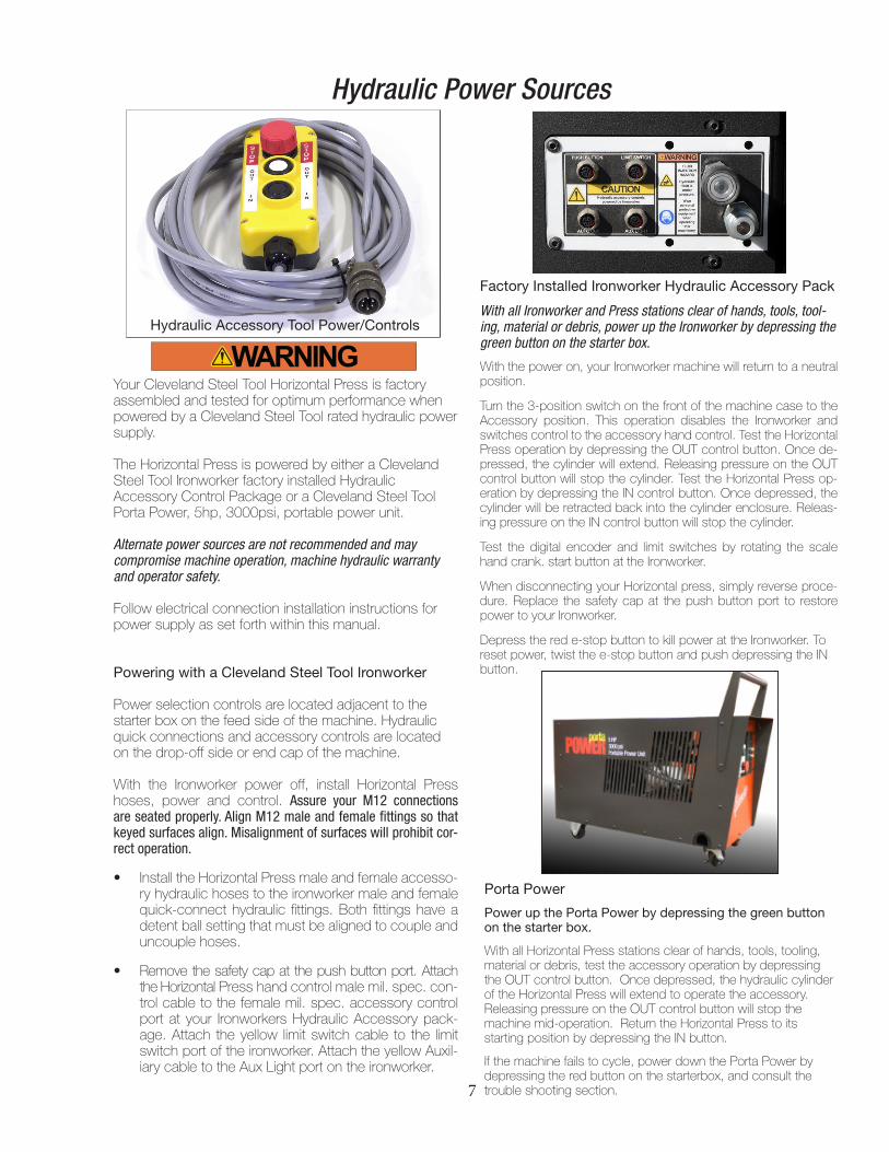
Hydraulic Power Sources
Hydraulic Accessory Tool Power/Controls

8
Machine Operations
Safe Operation
Observe the following guidelines when performing Press operations.
• Operator safety / Safe work zone Applying pressure to parts or assemblies can fail the part being worked, fail a part adjacent to the work or fail the pressing tool. Failed parts can become airborne projectiles with deadly force. Protect yourself with appropriate per-sonal protective equipment when operating the press. Protect others by defining a safe work zone for press use and limiting access to the press operator.
• Press Inspection Press operations may generate con-cussive failure to mechanical parts. Although Cleve-land Steel Tool press machinery is fabricated with both bolted and welded construction, concussive failure is a possibility over time or with extreme use. Prior to any press operation, visually check all bolted and welded connections for failure. All bolts must be tight and welds intact. Failure to verify the structural integrity of the machinery may result in workpiece shift, part ejection, operator injury or machinery damage.
The Cleveland Steel Tool Horizontal Press is capable of many cold forming or pressing functions. This manual outlines the basic functions associated with typical Horizontal Press operations and is neither intended to create a comprehensive list of, nor describe every oper-ation possible with this versatile tool. Horizontal Press operations are dangerous and require extreme care and caution in the preparation of the material being worked, the press set-up and the pressing operation. Please refer to the following setup, safe operation and press operation sections for an understanding of the potential hazards present in any horizontal pressing operation.
With 20 Tons of force, the Cleveland Steel Tool Horizontal Press features robust engineering and construction and is designed for years of heavy duty service when powered by a Cleveland Steel Tool Ironworker or Porta Power por-table hydraulic unit. Please refer to Cleveland Steel Tool power source manual prior to operation of machinery.
• Workpiece Inspection Workpiece failure is the most common source of injury during press operations. Take time to thoroughly understand the workpiece. Never apply pressure to unstable material, objects, round shapes, balls, springs or any item with elastic, spring-back tendencies. Confirm the material proper-ties of the workpiece will withstand the pressure to be exerted by the press. Confirm that workpiece items are stripped down to their simplest form. Many com-ponents contain unseen items that could fail during the press operation. Remove all sub components known to the workpiece prior to a pressing operation. Workpiece must be clean and free of substances at the pressing surface that would allow the pressing surfaces to slip under load.
• Workpiece Support Workpiece failure may be a result of improper or inadequate workpiece support. Ad-equate support for the workpiece must be present through the entirety of the press operation. Under-stand your workpiece and confirm that the workpiece support system you employ will withstand the pres-sure being exerted through the press operation.
• Safe use of tooling Cleveland Steel Tool provides standard tooling supplied with the HP20T. This tooling is designed to be safely used with the arbor support. Custom tooling is available for special applications. Care must be taken when selecting press tooling. Se-lect tooling that is designed and rated for the specific application. Press with the shortest, most compact, tool length available. Confirm that press tooling and workpiece are aligned and follows a direct press path. Misaligned loads may fail the press tooling or work-piece and cause operator injury or damage to the machinery.
• Special Fits Not all parts were designed and en-gineered to be removed or applied with a press. When inspecting your workpiece, confirm any press tolerances, environmental, heating, cooling or fixative requirements that require special care prior to initiating the press operation. Do not proceed with a press op-eration without acknowledgement that the workpiece is pressable.
• Do not force press Consider the rating of the press and the work at hand. Gradually build pressure being applied to the workpiece. Carefully observe the workpiece to avoid tooling misalignment or workpiece failure. Observe the press as it reacts under load. Do not overload the press. Take care to avoid parts falling from the workpiece.

9
Operations Diagram
Arbor Support
Digital Readout Tooling Arbor
UniversalTooling Block
Scale with Pointer
Scale Crank
Table Extension Bulk Head
Hydraulic Hoses
Table
Arbor Crank
Base Cabinet
Leveling Feet

Base Cabinet
Your HP20T has been factory tested and setup to imme-diately “plug and play” with your Cleveland Steel Tool Iron-worker Hydraulic Accessory Pack or Porta Power, portable hydraulic unit.
The Press is constructed of six basic assemblies: the base cabinet, the table, the hydraulic cylinder enclosure, mea-suring system, tooling block and arbor support.
Beyond providing tooling storage, the base cabinet of the HP20T accommodates leveling and height adjustment of up to 2". Adjust for additional table height by rotating the leveling feet clockwise or counterclockwise and follow-ing instructions for hard-mounting the machinery to the floor. The base cabinet also houses the digital encoder / auto-stop adjustment, tool squaring function and extension table bulkheads.
Table
The HP20T working surface is a solid plate of machined A36 steel. The surface is ground and machined to allow for the installation of the 20 ton hydraulic ram, measuring hardware, hardened bushings and the tooling steel wear plate. The wear plate is S7 tool steel and has been ground flush with the prime table surface. Both the prime table and wear plate are protected with a surface applied rust inhibitor which will require maintenance over time to prevent rust and corrosion. The 24" x 42" table may be enlarged by adding table extensions to the table bulkheads located in the base cabinet.
10
SetupHydraulic Cylinder
The HP20T is powered by either your Cleveland Steel Tool Ironworker or Cleveland Steel Tool Porta Power, 3000psi portable hydraulic power source. The 20’ umbilical hosing and quick connect hardware supply hydraulic power to the hydraulic cylinder within the HP20T. The HP20T cylinder features a 2.25" ram for tooling stability, 20 tons of pres-sure and a 10" maximum stroke. Cylinder stroke is manip-ulated with a simple hand-wheel and measured with a roller encoder and digital readout at the table surface accurate to 0.01".
Measuring System
The HP20T features a roller encoder driven measuring sys-tem. Hand crank activated, the measuring system moves a proximity switch and marker along a graduated scale. The proximity switch controls cylinder stroke and can be located anywhere along the graduated scale allowing for up to 10" of stroke travel. The digital readout provides for fine adjustment to 0.01".
When the machine is first received the limit scale will be set to 0, this will stop the ram from extending. To extend the cylinder rotate the scale hand crank. The cylinder will extend as far as the pointer and scale indicate. The digital readout can help with seeing precise measurements, and can also be reset with a face button.

• For Operator safety, wear personal protective equip-ment, clear the work zone of any tooling or debris prior to powering the machinery on.
• Perform press inspection.• Perform workpiece inspection.• Turn power source on. • Retract ram, install press tooling.• Adjust tooling as necessary to achieve the shortest
ram travel. • Safely load, position and support workpiece.• Align and secure tooling to the tooling block.• Carefully, slowly, extend ram and tooling to meet press
site. Preload the workpiece and observe workpiece support and tooling alignment. Observe the preloaded condition from multiple angles to assure that the press tooling is in alignment with the ram and workpiece. If unstable, reverse ram, reset workpiece and re-align press tooling.
• Gradually build pressure to complete the press oper-ation.
• Retract the ram to relieve hydraulic pressure following the press operation.
11
Press Operations
Arbor Support
The arbor support is a hinged steel bar that, when attached to the tooling arbor, rigidly supports the arbor and eliminates a potential cantilever tooling failure. THE ARBOR SUPPORT STRUCTURE IS REQUIRED TO BE ENGAGED IN ALL STANDARD PRESSING OPERATIONS.
Tooling Block
The tooling block of the HP20T is fixed to the ram of the cylinder. The machined surface features horizontal T-slots for custom tooling applications and a vertical slot for stan-dard 6" brake tooling. Tooling fixes to the vertical slot with 4 set-screws. The tooling block slides on two, adjustable gib-pins recessed into the machined surface. The gib-pins provide leveling and bearing surfaces that will wear over time. Periodically adjust the gib-pins to ensure the ram is parallel to the table surface.

12
Quality parts are dependent upon conscientious setup, operation and maintenance of your Horizontal Press. Physically review your Horizontal Press prior to any operation. Confirm all static components are tight in the assembly. Confirm all moving components are free of obstruction. Confirm all tooling and assemblies are properly seated within the assembly.
Troubleshooting
Problem Solution
Horizontal Press Inoperable Check accessory control switch Check shop press male 4-pin power cable is connected to female limit switch port. Check hand control Mil Spec male power cable is connected to female Mil Spec control port Note: Auto Cut port will NOT power the Horizontal Press accessory.
Rough Cylinder Operation Check Hydraulic fluid level at power source. Check hoses for correct installation.

www.clevelandsteeltool.com474 E. 105th St. • Cleveland, OH 44108
800-446-4402