horizontal remediation well technology: access the

1
Background: An active chemical manufacturer in New South Wales, Australia needed a way to target a source area beneath the site that had both above ground and underground storage tanks. The main source area of the plume was centered directly under the processing area in the facility and three USTs. Horizontal wells were selected as the best choice to target the source, which allowed for direct contact of the injection well screen within the source area. Approach and Activities: Directional Technologies, Inc. installed three (3) horizontal injection wells beneath surface obstructions while avoiding subsurface utilities and the underground storage tanks. The HRWs were installed via blind method, meaning exit locations for the wells were not required. Blind horizontal wells further minimized disturbance to facility operations. The starting angles of the well paths were adjusted in the field resulting in fan shaped horizontal well pattern allowing for better coverage of the plume. The horizontal well screens were designed for site specific remedial goals and engineered to ensure even flow distribution of stabilized hydrogen peroxide and chelated ferrous sulphate solution. Case Study #4: Horizontal Injection Beneath Chemical Manufacturing Facility - Australia Case Study #1: Horizontal AS/SVE Under Intersection Florida Background: Petroleum contamination from above ground storage tanks at a bulk fuel storage terminal in central Florida required onsite and offsite in-situ remediation of three target areas. Approach and Activities: Twenty-one horizontal biosparge wells, totaling 13,000+ linear feet, were installed to remediate three areas. On-site HRWs remediated underneath driveways, fueling racks, and ASTs. Off-site HRWs extended across busy 4-lane roads, under an operating gasoline station, and a warehouse building. 1-877-788-4HRW www.directionaltech.com Horizontal Remediation Well Technology: Access the Inaccessible to Expedite AST and UST Site Cleanup Kyle Carlton P.G., Directional Technologies, Senior Geologist Results: The remediation system consists of two progressive cavity pumps connected to 34,000 liter (9,000 gallon) tanks capable of injecting tens of thousands of liters of reagent into the subsurface over relatively short periods of time. Initial injection successfully influenced the groundwater by creating groundwater mounding of 40 centimeters (16 inches) and temperature increases observed at nearby groundwater monitoring wells. Case Study #2: Horizontal Biosparge Wells at Bulk Petroleum Terminal - Florida Results:. The Horizontal SVE system provided 4-inches of mercury vacuum and 1,100 actual cubic feet per minute (acfm) of influent airflow. The Horizontal air-sparge compressor operated at 12 pounds per square inch (psi) with a measured airflow of 100 scfm. During the first month of system operation the estimated rate of mass removal was 12.21 pounds of hydrocarbons per day. The radius of influence of the horizontal AS/SVE wells extended over the entire area of the intersection. After only 6 months of operation, an estimated 36% of the mass in the target zone has been remediated. INTRODUCTION: Horizontal remediation well (HRW) technology continues to make major strides for the environmental industry by enabling in- situ remediation of AST and UST sites previously considered unfeasible. Installation of HRWs with horizontal directional drilling (HDD) accesses contaminated areas beyond the reach of vertical drilling techniques, significantly diminishing overall remedial duration and long-term costs. Whether target remediation zones are beneath storage tanks, buildings, roadways, waterways, and other areas difficult to access, HRW/HDD technology facilitates remediation using a wide range of in-situ methods including: Soil Vapor Extraction Air Sparging Vapor Intrusion Mitigation Bioamendment Injection Groundwater Control/Dewatering Ozone Sparge Dual Phase Extraction Chemical Oxidation/ISCO Injection Electrical Resistive Heating Case Study #3: Horizontal Soil Vapor Extraction (HSVE), Former Petroleum Storage Facility New York Remedial Design: 21 Horizontal Biosparge Wells, installed blind method, constructed of 3-inch HDPE, screen at 35 feet BGS. Approach and Activities: After mobilization and upon set-up, it was discovered that the foundation wall was deeper than the plans had specified. With this new information, the Directional Technologies' team quickly collaborated with the consultant for a new design and solution which kept the project moving forward. The HSVE screens ranged from 120 feet to 220 feet in length with each placed at a depth of four to five feet below the slab to avoid utilities and to stay above the groundwater table. Horizontal Sub-Slab SVE well layout Background: As part of the Corrective Action Plan submitted to NYSDEC, the consultant selected Horizontal SVE to expand the on-site vapor extraction system. Directional Technologies worked with the consultant on the horizontal well screen design and well layout of the HSVE wells, spaced 50-feet apart, and constructed with 4-inch Schedule 80 PVC materials. Directional Technologies, Inc. brings 25 years of horizontal remediation well design and installation experience and expertise to your project. Background: Located near downtown Tallahassee, Florida, the site is the former Gary Johnson Tire facility which operated as an automobile service facility and gasoline station for several decades. Over the decades, groundwater flow toward the south transferred contamination diagonally across the intersection, making it virtually impossible to gain access to the plume through vertical wells. Approach and Activities: The remediation approach selected was the installation of four pairs of horizontal AS/SVE wells. Four total horizontal AS wells were installed beneath the intersection at target depths of 33 feet bls within the saturated zone, approximately 7 feet below the average groundwater table. Each AS well was coupled with a horizontal SVE well installed directly above the AS well at depths of approximately 20 feet BLS within the vadose zone. The horizontal AS/SVE wells were constructed of 4-inch HDPE with software engineered well screen for desired airflow rates. Horizontal AS/SVE well layout Analytical Results after 1 Year of Operation Horizontal Injection well layouts HIW profiles Drill bit tracking beneath ASTs

Upload: others

Post on 27-Feb-2022

2 views

Category:

Documents


0 download

TRANSCRIPT

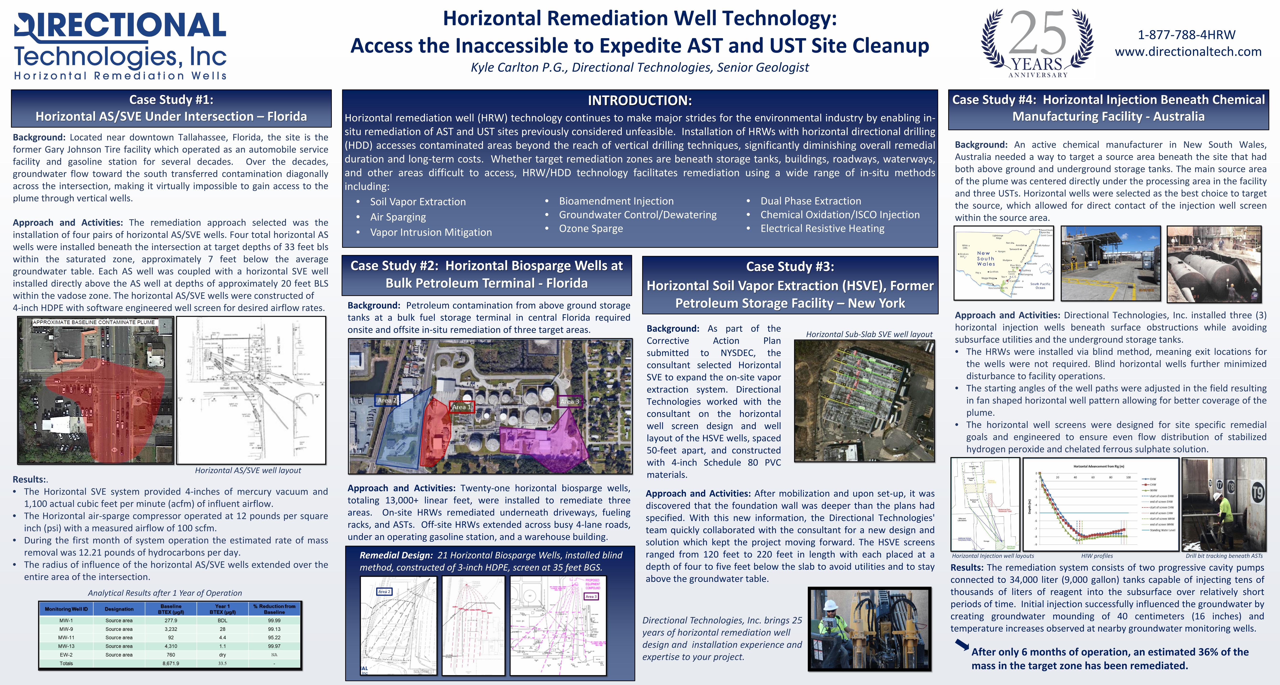
Background: An active chemical manufacturer in New South Wales,Australia needed a way to target a source area beneath the site that hadboth above ground and underground storage tanks. The main source areaof the plume was centered directly under the processing area in the facilityand three USTs. Horizontal wells were selected as the best choice to targetthe source, which allowed for direct contact of the injection well screenwithin the source area.

Approach and Activities: Directional Technologies, Inc. installed three (3)horizontal injection wells beneath surface obstructions while avoidingsubsurface utilities and the underground storage tanks.• The HRWs were installed via blind method, meaning exit locations for

the wells were not required. Blind horizontal wells further minimizeddisturbance to facility operations.

• The starting angles of the well paths were adjusted in the field resultingin fan shaped horizontal well pattern allowing for better coverage of theplume.

• The horizontal well screens were designed for site specific remedialgoals and engineered to ensure even flow distribution of stabilizedhydrogen peroxide and chelated ferrous sulphate solution.

Case Study #4: Horizontal Injection Beneath Chemical Manufacturing Facility - Australia

Case Study #1:Horizontal AS/SVE Under Intersection – Florida

Background: Petroleum contamination from above ground storagetanks at a bulk fuel storage terminal in central Florida requiredonsite and offsite in-situ remediation of three target areas.

Approach and Activities: Twenty-one horizontal biosparge wells,totaling 13,000+ linear feet, were installed to remediate threeareas. On-site HRWs remediated underneath driveways, fuelingracks, and ASTs. Off-site HRWs extended across busy 4-lane roads,under an operating gasoline station, and a warehouse building.

1-877-788-4HRW www.directionaltech.com

Horizontal Remediation Well Technology:Access the Inaccessible to Expedite AST and UST Site Cleanup

Kyle Carlton P.G., Directional Technologies, Senior Geologist

Results: The remediation system consists of two progressive cavity pumpsconnected to 34,000 liter (9,000 gallon) tanks capable of injecting tens ofthousands of liters of reagent into the subsurface over relatively shortperiods of time. Initial injection successfully influenced the groundwater bycreating groundwater mounding of 40 centimeters (16 inches) andtemperature increases observed at nearby groundwater monitoring wells.

Case Study #2: Horizontal Biosparge Wells at Bulk Petroleum Terminal - Florida

Results:.• The Horizontal SVE system provided 4-inches of mercury vacuum and

1,100 actual cubic feet per minute (acfm) of influent airflow.• The Horizontal air-sparge compressor operated at 12 pounds per square

inch (psi) with a measured airflow of 100 scfm.• During the first month of system operation the estimated rate of mass

removal was 12.21 pounds of hydrocarbons per day.• The radius of influence of the horizontal AS/SVE wells extended over the

entire area of the intersection.

After only 6 months of operation, an estimated 36% of the mass in the target zone has been remediated.

INTRODUCTION:Horizontal remediation well (HRW) technology continues to make major strides for the environmental industry by enabling in-situ remediation of AST and UST sites previously considered unfeasible. Installation of HRWs with horizontal directional drilling(HDD) accesses contaminated areas beyond the reach of vertical drilling techniques, significantly diminishing overall remedialduration and long-term costs. Whether target remediation zones are beneath storage tanks, buildings, roadways, waterways,and other areas difficult to access, HRW/HDD technology facilitates remediation using a wide range of in-situ methodsincluding:

• Soil Vapor Extraction• Air Sparging• Vapor Intrusion Mitigation

• Bioamendment Injection• Groundwater Control/Dewatering• Ozone Sparge

• Dual Phase Extraction• Chemical Oxidation/ISCO Injection• Electrical Resistive Heating

Case Study #3:Horizontal Soil Vapor Extraction (HSVE), Former

Petroleum Storage Facility – New York

Remedial Design: 21 Horizontal Biosparge Wells, installed blind method, constructed of 3-inch HDPE, screen at 35 feet BGS.

Approach and Activities: After mobilization and upon set-up, it wasdiscovered that the foundation wall was deeper than the plans hadspecified. With this new information, the Directional Technologies'team quickly collaborated with the consultant for a new design andsolution which kept the project moving forward. The HSVE screensranged from 120 feet to 220 feet in length with each placed at adepth of four to five feet below the slab to avoid utilities and to stayabove the groundwater table.

Horizontal Sub-Slab SVE well layoutBackground: As part of theCorrective Action Plansubmitted to NYSDEC, theconsultant selected HorizontalSVE to expand the on-site vaporextraction system. DirectionalTechnologies worked with theconsultant on the horizontalwell screen design and welllayout of the HSVE wells, spaced50-feet apart, and constructedwith 4-inch Schedule 80 PVCmaterials.

Directional Technologies, Inc. brings 25 years of horizontal remediation well design and installation experience and expertise to your project.

Background: Located near downtown Tallahassee, Florida, the site is theformer Gary Johnson Tire facility which operated as an automobile servicefacility and gasoline station for several decades. Over the decades,groundwater flow toward the south transferred contamination diagonallyacross the intersection, making it virtually impossible to gain access to theplume through vertical wells.

Approach and Activities: The remediation approach selected was theinstallation of four pairs of horizontal AS/SVE wells. Four total horizontal ASwells were installed beneath the intersection at target depths of 33 feet blswithin the saturated zone, approximately 7 feet below the averagegroundwater table. Each AS well was coupled with a horizontal SVE wellinstalled directly above the AS well at depths of approximately 20 feet BLSwithin the vadose zone. The horizontal AS/SVE wells were constructed of4-inch HDPE with software engineered well screen for desired airflow rates.

Horizontal AS/SVE well layout

Analytical Results after 1 Year of Operation

Horizontal Injection well layouts HIW profiles Drill bit tracking beneath ASTs