hose and connector installation guide
TRANSCRIPT

Hose and Connector Installation Guide 1
Hose and Connector Installation Guide
1
st Edition
Created: October 2012

Hose and Connector Installation Guide 2
Installation Assembly Criteria – Introduction While the success of a hydraulic fluid conveyance system weighs heavily on its design, the assembly of the fluid lines is just as important to the longevity and success of the system. Fluid Lines Designers are provided with various design analysis tools such as the Fluid Lines Design Software (FLD) to design a successful lines system. But unless the Lines Assembler effectively executes routing this design, the efforts put into designing the intelligent system are wasted, resulting in leaks, warranty claims, and customer dissatisfaction.

Hose and Connector Installation Guide 3
Table of Contents Hose and Assembly Identification...................................................... 4
Cat Hose Identification ................................................................ 4
Hose Assembly Identification ...................................................... 5
Types of Couplings ..................................................................... 5
Installation Process ........................................................................... 8
Contamination Controls............................................................... 8
Step-by-Step Installation Process ............................................... 9
Four-Bolt Flanges...................................................................... 13
Hose Twist ...................................................................................... 15
Assembly for a Twist-free Installation ........................................ 16
Consequential Failure Story Board............................................ 16
Path of Hose ................................................................................... 18
Assembly for optimal Hose Path Installation.............................. 19
Consequential Failure Story Board............................................ 22
Abrasion and Contact...................................................................... 23
Types of Abrasion ..................................................................... 24
How to Avoid Abrasion.............................................................. 26
Consequential Failure Story Board............................................ 27
Clips and Clamps ............................................................................ 29
Types of Clamps ....................................................................... 30
Guidelines for Correct Clamping ............................................... 31
Routing Taped Hose Assemblies .............................................. 33
Seals and Lubricant......................................................................... 35
Hose and Connector Installation Guide 4
Installation Assembly Criteria – Hose and Assembly Identification
Cat Hose Identification
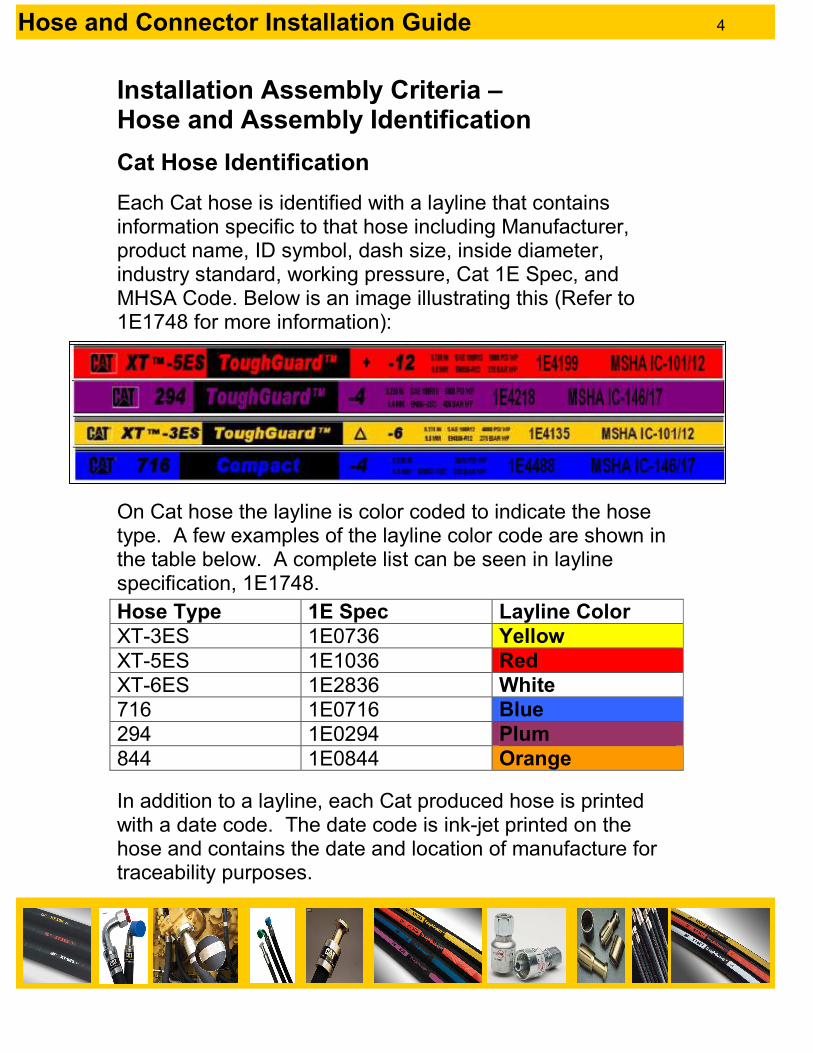
Each Cat hose is identified with a layline that contains information specific to that hose including Manufacturer, product name, ID symbol, dash size, inside diameter, industry standard, working pressure, Cat 1E Spec, and MHSA Code. Below is an image illustrating this (Refer to 1E1748 for more information):
On Cat hose the layline is color coded to indicate the hose type. A few examples of the layline color code are shown in the table below. A complete list can be seen in layline specification, 1E1748.
In addition to a layline, each Cat produced hose is printed with a date code. The date code is ink-jet printed on the hose and contains the date and location of manufacture for traceability purposes.
Hose Type 1E Spec Layline Color
XT-3ES 1E0736 Yellow
XT-5ES 1E1036 Red
XT-6ES 1E2836 White
716 1E0716 Blue
294 1E0294 Plum
844 1E0844 Orange
Hose and Connector Installation Guide 5
Hose Assembly Identification
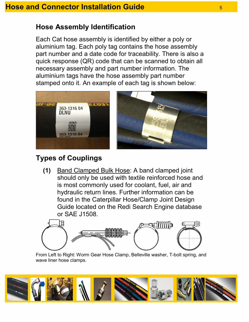
Each Cat hose assembly is identified by either a poly or aluminium tag. Each poly tag contains the hose assembly part number and a date code for traceability. There is also a quick response (QR) code that can be scanned to obtain all necessary assembly and part number information. The aluminium tags have the hose assembly part number stamped onto it. An example of each tag is shown below:
Types of Couplings
(1) Band Clamped Bulk Hose: A band clamped joint should only be used with textile reinforced hose and is most commonly used for coolant, fuel, air and hydraulic return lines. Further information can be found in the Caterpillar Hose/Clamp Joint Design Guide located on the Redi Search Engine database or SAE J1508.
From Left to Right: Worm Gear Hose Clamp, Belleville washer, T-bolt spring, and wave liner hose clamps.

Hose and Connector Installation Guide 6
(2) Permanent Crimped Hose Assembly: The permanent coupling (1E2115) consists of a head, stem, and shell, shown below. a. Threaded Coupling b. Snap to Connect Coupling c. Flange Coupling.
i. Code 61: Pressure rating of 3,000-5,000 PS depending on size and angle of the coupling.
ii. Code 62: Pressure rating of 3,000-6,000 PSI depending on size and angle of the coupling.
Head
Stem Swivel
Nut Shell
ORFS (O Ring Face Seal)
Shell Head Stem
Split Flange (Code 61)

Hose and Connector Installation Guide 7
(3) Reusable Hose Assembly a. Collet-Type Coupling: The collet-type coupling
(1E2189) is used on high pressure XT hose assemblies. This type of coupling requires special equipment to assemble and disassemble the coupling on the hose assembly.
b. Screw-Type Coupling: The screw-type coupling (1E2436) is used on low pressure applications such as fuel lines. This type of coupling can be assembled with hand tools alone.
1. Reusable Hose Assembly
XT Reusable Coupling Assembly Sequence Refer to NEHS0746-02 for additional information on the tooling and assembly sequence for XT Reusable Couplings.
Resources that exist within Cat for coupling identification are the Coupling Identification Wall Chart (PEWP4128) and the Caterpillar Coupling Identification Guide (PECP2007).

Hose and Connector Installation Guide 8
Hose Installation Assembly Criteria – Installation Process
Key Point Contamination Controls
The importance of contamination controls cannot be stressed enough when it comes to hydraulic fluid lines. An entire fluid system can be compromised by pre-installation contamination. Do NOT remove the contamination caps or plugs from the hose assembly until just before installing the assembly. This will insure the best case scenario for fluid lines to be protected from contaminants.
Also note: � Floors should not be used as
storage surfaces for hose assemblies.
� Dedicated racks, metal skids, pallets or tubs must be used and protected with lids or protective coverings.
� Hoses should be stored on racks where the ends are covered and do not touch the ground.

Hose and Connector Installation Guide 9
Step-by-Step Installation Process
(1) Remove contamination controls from hose ends and examine the hose assembly prior to machine installation for the following (SAE J1273): a. Verify the hose part number, hose length, and
routing for compliance with the original design/drawing or with the provided schematic.
b. Assemblies for nonconformities such as faulty or incomplete crimp, abrasion, or cut(s) on the hose.
c. Fitting sealing surfaces for burrs, nicks, or other damage.
d. *Note: Handle the hose with care during installation. Kinking or bending the hose beyond the minimum bend radius can reduce hose life.
e. *Note: When replacing hose assemblies in existing systems, verify that the replacement is of equal specification to the original assembly.
(2) Assemble the first coupling onto its designated port
adapter. Do NOT tighten the coupling to torque specification yet, finger tight will suffice temporarily. a. When assembling a hose with an angled coupling
and a straight coupling, ALWAYS assemble the end with the angled coupling first. This will allow for easier installation of the second coupling and overall hose assembly.
b. On hose assemblies with two straight couplings, locate the end with the label in the most visible location for later service.

Hose and Connector Installation Guide 10
(3) Route the hose assembly to its second port connection and assemble the coupling onto the adapter. Refer to the outlined sections of this document, most notably “Path of Hose,” to ensure correct and optimal routing (i.e. Hose Twisting, Abrasion, Correct Clamping, etc).
(4) Once both hose ends are connected and the hose
routing is finalized, tighten each coupling to its respective torque specification. Mark each coupling to signify that it has been tightened to torque spec. Process is as follows (3 steps):
1. Rotate the coupling to the proper angle for the hose routing and hand tighten. Mark the connection with a marker.
� Mark a continuous line across the joint. � Mark only the connection that is being
torqued. � Mark ONLY after hand tightening.
*Note that an adapter, NOT hose coupling is being pictured. The process is the same for both.

Hose and Connector Installation Guide 11
2. Tighten fitting to specified torque using only certified torque wrenches.
a. The use of a back-up wrench is required when
possible. One is used for the tightening of the coupling nut onto the adapter while the second wrench is used to keep the crimp shell from rotating and this twisting the hose. A hose twist can result from not using a back-up wrench.
b. When tightening, make the best effort to keep the wrench at a 90° angle to the coupling for the most consistent and accurate torque application. *Refer to Caterpillar specification 1E0279 for further and more detailed instructions.
Fig 1. Torque applied at 90º, 166 Nm achieved.

Hose and Connector Installation Guide 12
Fig 2. Torque applied at approx. 30º, 132 Nm achieved.
Notice that incorrect application of the wrench results in 34Nm reduction in assembly torque. This could result in loosening of the joint and leakage during service as well as more energy required by the assembler to achieve the torque spec.
3. Inspect to confirm that the lines between the two mating hydraulic components are no longer aligned.

Hose and Connector Installation Guide 13
Four-Bolt Flanges
1. Position the flanges so that the bottom surface of the
flange is parallel to the port. 2. Evenly install bolts hand-tight, keeping the gap between
flanges at a minimum. The maximum gap permitted after final tightening is 4 mm for the summed total of both sides. For example, a flange could have 2 mm on both sides, or zero on one side while having 4 mm on the other.
3. If the bolt torque is not specified on the drawing, tighten bolts with 1E0279A or 1E0279B.
4. Use one of the following torque methods from the illustration on the next page:

Hose and Connector Installation Guide 14

Hose and Connector Installation Guide 15
Hose Installation Assembly Criteria –
Hose Twist
Key Point
Since hose is flexible it is possible to twist it along its own axis, either during installation or during its operational movement. Avoiding twist during installation depends largely upon good assembly practice by the mechanic. It is also important to understand the hose movement during machine operation to be able to predict and eliminate potential twist in the hose due to movement. Twisting a hose can cause a major reduction in hose life. Twisting a high-pressure hose only 5° can reduce service life by 70%, and 7° of twist can reduce service life up to 90%.
Correct Incorrect

Hose and Connector Installation Guide 16
Assembly for a Twist-free Installation
(1) Assemble angled couplings first. This will allow for easier installation of the second coupling and overall hose assembly.
(2) Use two wrenches when tightening the hose ends, one on the swivel nut and one on the back-up hex of the coupling to avoid twisting the hose while tightening.
(3) Make sure the sealing face of the coupling meets flat with the sealing surface of the adapter to ensure a leak-free and straight connection between the ports.
(4) Ensure the hose is untwisted and routed correctly in a relaxed position before tightening to torque specification.
Consequential Failure Story Board Because of the flexible nature of hose it is tempting to allow it to twist during installation or even do so deliberately to force the hose away from an obstruction. It is also easy to forget that when a hose moves in more than one plane a resultant twist occurs.
Hose and Connector Installation Guide 17
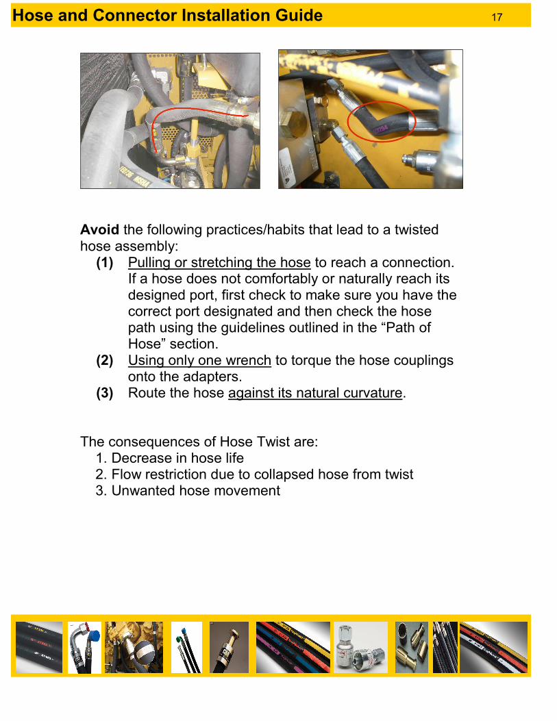
Avoid the following practices/habits that lead to a twisted hose assembly:
(1) Pulling or stretching the hose to reach a connection. If a hose does not comfortably or naturally reach its designed port, first check to make sure you have the correct port designated and then check the hose path using the guidelines outlined in the “Path of Hose” section.
(2) Using only one wrench to torque the hose couplings onto the adapters.
(3) Route the hose against its natural curvature. The consequences of Hose Twist are:
1. Decrease in hose life 2. Flow restriction due to collapsed hose from twist 3. Unwanted hose movement

Hose and Connector Installation Guide 18
Hose Installation Assembly Criteria – Path of Hose
Key Point
The ‘natural curvature’ of the hose should follow the installed hose shape, if possible. On hose with straight couplings this can be achieved with careful assembly, but this can be more difficult with angled couplings. When assembling a hose with angled couplings, always assemble the hose end with the angled coupling first. This will allow for easier installation of the second coupling and overall hose assembly.
Natural Curvature The term ‘natural curvature’ refers to the tendency of a hose to curve with no external force applied. Hose built on a flexible mandrel is cured while coiled on a reel and will take the curvature of the reel. Hose will also take the shape of the reels used for packaging if left on the reel for any period of time. This effect usually has minimal impact on service life but it can have a significant effect on the installation of larger, stiffer hoses.

Hose and Connector Installation Guide 19
Assembly for optimal Hose Path Installation
Below is a list of guidelines for hose assembly on machines. While it is initially the designer’s responsibility to ensure the route of each hose is “clean” and effective, the assembler is just as important to ensure the hoses are routed well (SAE J1273).
(1) Hoses should run parallel to each other and avoid crossing.
(2) Hoses should bend only in one plane. Even in a static installation contraction due to the pressurisation of the hose will induce a torsional twisintg load in the hose.
(3) Prevent the hose from contacting and rubbing on sharp edges, surfaces, electrical cables and harnesses, and hot or moving objects.

Hose and Connector Installation Guide 20
(4) Large hose loops should be aligned with the natural curvature of the hose. This will ensure the path of a moving hose loop remains in the intended plane of motion throughout the full range of movement and avoids kicking out to the side.
(5) Do not exceed the minimum bend radius of the hose being installed. As the hose exits the coupling the hose should remain straight out of the coupling for at least one hose diameter before bending. Hoses bent immediately at the coupling will have a reduced life. L=one hose diameter in the image below.
Hose and Connector Installation Guide 21
(6) Hoses should not be routed in such a way to be easily used as a step or grab handle.
(7) Be sure to not allow fluid to flow or drip on critical or hot components if disconnecting a hose for replacement or service.
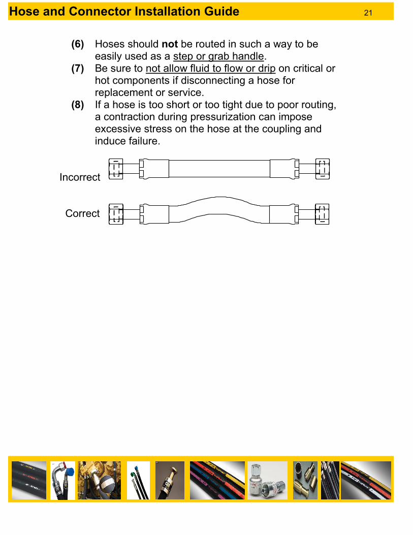
(8) If a hose is too short or too tight due to poor routing, a contraction during pressurization can impose excessive stress on the hose at the coupling and induce failure.
Incorrect Correct

Hose and Connector Installation Guide 22
Consequential Failure Story Board
Because of the flexible nature of hose it is tempting to route hoses in multiple directions while disregarding the designed route. These photos are visual examples of what can occur due to the assembly of a poor hose path.
Figure 2: Hose bent at coupling.
Figure 3: Hose exceeds bend radius (yellow hose).
The consequences of poor routing are:
1. Decrease in hose life 2. Flow restriction due to exceeded bend radius 3. Abrasion 4. Hose failure
Figure 1: Hose too short.

Hose and Connector Installation Guide 23
Hose Installation Assembly Criteria – Abrasion and Contact
Key Point Be Aware of Interference at:
The hose – Although the resilient rubber surface might appear to withstand impact, the damage to the wire reinforcement below can significantly weaken the hose and reduce its life. The coupling – Bending and distortion of the couplings can effect:
• Life of the hose assembly
• The performance due to restriction in the flow area
• The sealing performance of the joint
• Assembly and service

Hose and Connector Installation Guide 24
Types of Abrasion
(1) Sharp Edge/Corner Abrasion: Heavy consideration and primarily avoidance should be given to hose clearance due to assembly and operational conditions. Can the sharp edge be smoothed off, edges bent over, round bar welded to contact point, a clamp be added, or a hose sleeve/guard installed.
(2) Hose to Hose
Abrasion: Consider the relative orientation of the 2 hoses – generally parallel contact will be less damaging than hoses crossing at 45 to 90 degrees. Hoses in close proximity may contact in certain operational modes, all should be considered and checked.
(3) Flat Surface Contact: No surface is truly smooth. In
a working environment abrasive materials can get caught in-between the hose and the surface. The hardness of a contacted surface relative to the hose cover is also a consideration when assessing the risk of wear to both. This is a minor risk.

Hose and Connector Installation Guide 25
(4) Moving Part Contact: Consideration should be given to the clearance due to assembly and operational conditions. 50 mm clearance is recommended.
(5) Small Radius
Corner: Like sharp edge abrasion, small radius corners can wear the hose cover down and cause abrasion leading to hose failure and/or decreased hose life.
Thermal Threats All of the heat sources below should be considered for suitability of the hose selected, risk of contact, and potential for oil spray to contact the heat source in the event of a hose or joint failure. Ensure at least 3” of clearance between hose and heat source.
- Extreme ambient temperatures - Point sources of radiant heat
such as exhausts and turbos - Flame

Hose and Connector Installation Guide 26
Electrical Threats All hoses having steel reinforcement have the potential to carry electric current. If the hose is in contact with an electrical harness or battery cable and the covers of both wear through, the hose will carry the current to ground.
How to Avoid Abrasion
In order to avoid abrasion/wear issues the strategy should be to:
Then, if necessary
Then, if necessary
1. Avoid Contact Use clamping and restraint techniques if required.
2. Modify Surfaces Ensure hose and contacted surface are suitably abrasion resistant (i.e. Tough Guard hose). Ensure abrasion resistance of installation is suitably validated.
3. Add guarding solutions Add the necessary guarding to hose and/or contacted surface.

Hose and Connector Installation Guide 27
Supporting Information and Training Opportunities Design Guides Caterpillar Safety Design Guide Hose Rub Reference Guide – HCMD Hydraulics Team, Decatur Caterpillar Standards J12.1 SAE Standards SAE J517
Consequential Failure Story Board
Contact with hose has worn through electrical harness.
Hose cover is worn to the reinforcement from 45º contact with another hose.

Hose and Connector Installation Guide 28
Hose cover is cut by edge of clip after 180 hours. The clip was too loose and reciprocating motion wore plastic from clip. The removal of the plastic exposed a sharp steel edge which cut cover.
Despite edge protection the hose cover has worn through to the reinforcement on this rig test after 104 K cycles.

Hose and Connector Installation Guide 29
Hose Installation Assembly Criteria – Clips and Clamps
Key Point
The type and positioning of hose retention or clamping hardware plays an important part in controlling the path of hose. This will apply to nominally static lines as well as lines designed to move in conjunction with other machine functions. Awareness and use of the natural curvature of the hose can help reduce the amount of clamping required. In reality, no line is truly static and although the hose may not be designed for movement it will still experience dynamic shock and vibration loadings from the machine as well as internally induced loadings from pressurization.
In both static and dynamic applications, the function of the clamping mechanism is to:
� Prevent the hose from contacting and rubbing on sharp edges, surfaces, electrical cables and harnesses, and hot or moving objects.
� Position the hose at the correct connection location for another fluid line or component.
*Safety Warning: Use caution when reaching around certain clips or clamps or while installing them. Some contain sharp edges that can easily cause a deep laceration.

Hose and Connector Installation Guide 30
Types of Clamps
*Note: Also, always make sure you are using the correct torque or tightening tool for the given clips/clamp. Using the incorrect tooling can compromise the effectiveness of the clip/clamp and decrease the life of the hose.
(1) P-Clips
(2) 2-Piece Clips
(3) Vibration Dampening

Hose and Connector Installation Guide 31
(4) Saddle Clips
(5) Tie Mounts & Straps
Guidelines for Correct Clamping
Make sure the clamp being used is sized correctly and not too large or too tight for the hose. A loose clamp will allow too much room for the hose to move and result in abrasion.

Hose and Connector Installation Guide 32
Do not clamp high and low pressure lines together as they will flex differently. Also, do not bundle a group of hoses together with a tie wrap. Hoses will still be able to move around within the bundle and create a non-parallel routing, which results in an abrasion risk.
Tie wraps should only be used for the retention of light, low pressure hose. Tie wraps will not prevent relative movement if used to strap high pressure hoses together and will result in hose wear and tie wrap failure.
Do NOT route a hose bend too tight through a clamp or clip. Hose should pass through the clamp with at least 1xOD of straight length on either side.

Hose and Connector Installation Guide 33
Routing Taped Hose Assemblies When routing taped assemblies, ideally, hose should be clamped on the tape marks. However, with all hose assemblies and taping there are tolerances. Hose assembly tolerances depend on the hose assembly length. The tolerances for hose assemblies are as follows (from J12.1):
Length (mm) Tolerance (mm)
< 300 ± 3
300 - 450 ± 5
450 - 900 ± 7
> 900 ± 1%
When hose assemblies differ from the nominal length there may be times that, although the hose is clamped on the tape marks, interference with other hoses or components occur. In situations where fouling occurs it is recommended that the clamping location be moved off the tape marks, as necessary, to prevent the interference. Since each machine will be different there will be some level of personal judgment required in each routing. An example of hose assembly tolerance affecting routing is shown below. The images below show the changes in hose assembly length that can occur when a hose assembly is built at nominal length called out on the print, image #1, versus the top of the tolerances, image #2. The images are slightly exaggerated to show potential issues.

Hose and Connector Installation Guide 34
When installing a hose assembly at the top of tolerance, like image #2, all the excess hose will be forced between the last tape mark and the coupling, as seen in image #3. To alleviate the issues created by the excess hose the clamps should be moved off the tape marks and the hose distributed as necessary to eliminate issues, as seen in image #4.
Forcing all the excess hose between the last tape mark and the coupling can cause routing issues like rubs between hoses, rubs between hose and machine components, and hose undesirably bending at coupling. Moving clamps off tape marks and spreading the excess hose over the length of the assembly helps to reduce the issues caused when all the excess hose is forced into one section of the assembly. Each installation will be different and discretion will have to be used when moving clamps off tape marks. When installing hose assemblies at the top of tolerance on some machines it will be best to spread the excess hose over the length of the assembly, while on other machines it will be best to move the excess hose between two different clamps to prevent hose rubs or fouling.
Image #1: Hose assembly built at nominal length called out on print.
Image #2: Hose assembly built at the top of tolerances called out on print.
Image #4: Hose assembly built at the top of tolerances and not clamped on tape marks,
the excess hose is spread over the length of the routing.
Image #3: Hose assembly built at the top of tolerances and clamped on tape marks.

Hose and Connector Installation Guide 35
Installation Assembly Criteria – Seals and Lubricant
Key Points
(1) Retention compounds and lubricants shall not be used on STOR/ORFS. (MJ1000-68)
Applications where a retention compound is approved and shall be used can be seen in Figures 1-2, “D”/Rectangular O-ring applications in ends of hose couplings. (1E4247)
(2) O-rings may be installed into a fitting/adapter without the use of a tool. However, installing a seal without the use of a tool places the seal at extreme risk of damage to the o-ring caused by the threads, and of o-ring spiraling. Therefore, it is recommended that appropriate tooling be used for the installation of O-rings. Refer to MJ1000-68 for further information on tooling selection and application.