hoses and accessories bellows contents - home | … design the correct fitting situation one must...
TRANSCRIPT

Hoses and AccessoriesBellows
1
All the information in this documentation has been compiled with the greatest of care.
Despite this we can bear no responsibility whatsoever for any errors present in the documentation. The recommendations are intended as guidelines.
www.eriks.info
1
All the information in this documentation has been compiled with the greatest of care.
Despite this we can bear no responsibility whatsoever for any errors present in the documentation. The recommendations are intended as guidelines.
www.eriks.info
Introduction ..................................................... 2Basic concepts bellows .................................... 3Rubber bellows ................................................ 16
RX® 49 series (fitting length: 100 mm) ............ 19® 49 blue ................................................. 21® 49 yellow ................................................ 22® 49 green ................................................. 23® 49 red ................................................. 24® 49 white ................................................. 25® 49 black ................................................. 27
RX® 50 series (fitting length: 130mm) ............ 28 ® 50 yellow nylon ....................................... 29® 50 yellow TW ....................................... 31® 50 yellow steel ....................................... 32® 50 green ............................................... 33® 50 orange ............................................... 34® 50 red aramide ...................................... 35® 50 red DW ............................................. 36® 50 red nylon ........................................... 37® 50 red PTFE .......................................... 38® 50 white ................................................ 39® 50 black/CR .......................................... 41
RX® 51 series .................................................. 42® 51 lilac .................................................. 44
RX® 55 series .................................................. 45® 55 yellow ................................................ 47® 55 green ................................................ 48® 55 red aramide ....................................... 49® 55 red nylon ........................................... 50® 55 white ................................................. 51
RX® 46 series ................................................... 52® 46 blue .................................................. 53® 46 yellow ................................................ 55® 46 grey .................................................. 56® 46 red nylon ........................................... 57® 46 red steel ........................................... 58
RX® 48 series .................................................. 59® 48 red ................................................... 61
RX® 61 series ................................................... 62® 61 yellow ................................................ 63® 61 red nylon ........................................... 64® protective cover ...................................... 65® liner ........................................................ 66
Contents
Various types of rubber bellows .......................... 67Question list for rubber bellows .......................... 68
RX® Stainless steel bellows ............................... 71 ® KS SS/ST PN16 ....................................... 71® KS SS PN16 ......................................... 72® KSi SS/ST PN16 ...................................... 73® KSi SS PN16 ......................................... 74® KBF SS/ST PN16 ................................... 75® KBF SS/SS PN16 ................................... 76® KBFi SS/ST PN16 ................................... 77® KBFi SS PN16 ......................................... 78® KBFL PN16 ............................................. 79® KST PN16 ............................................. 80® KFFT PN16 ............................................. 81® KS2T PN16 ............................................. 82® KFF2T PN16 ........................................... 83® KSG PN16 ............................................. 84® KFFG PN16 ............................................. 86® KSC PN16 ............................................. 88® KFFC PN16 ............................................. 90® KS-HP PN40 ........................................... 92® KS-HP PN64 ........................................... 93® KS-HP PN100 ......................................... 94® KS-HP PN160 ......................................... 95® KS-HP PN250 ......................................... 96® KSU PN2.5 .............................................. 97
Question list for metal bellows ............................. 98
RX® PTFE bellows .............................................. 100® 1002 white .............................................. 100® 1002 black .............................................. 101® 1003 white .............................................. 102® 1003 black .............................................. 103® 80 R-HD 106 ......................................... 104® 902 .......................................................... 105® 903 .......................................................... 106® 905 .......................................................... 107® 954 .......................................................... 108® 958 .......................................................... 109® 959 .......................................................... 110
FRENZELIT fabric bellows ................................ 111Designs .............................................................. 117Important tips for transport, storage and assembly 122Assembly of non-endless bellows ........................ 123Question list for fabric bellows ............................. 124
Notes .................................................................. 126

Hoses and Accessories
2
All the information in this documentation has been compiled with the greatest of care.
Despite this we can bear no responsibility whatsoever for any errors present in the documentation. The recommendations are intended as guidelines.
www.eriks.info
Basic concepts of bellows
Introduction
All installations may be subjected to movements. These movements can vary from very slow (thermal expansion or shrinking movements) to very fast (vibrations).Thermal expansion can result in adverse material stresses in piping. Fitting bellows can prevent these undesired material stresses.
Vibrations can also cause stresses, as well as unpleasant noise in the work and living environment. Fitting bellows can counteract this.
® bellows.The faultless functioning of bellows requires fitting to take place particularly carefully according to the instructions, and the pressure and temperature limits concerned may not be exceeded.
Our knowledge and supply capabilities in this field offer you the opportunity to choose the bellow to optimally meet your requirements.
Compensators
3
All the information in this documentation has been compiled with the greatest of care.
Despite this we can bear no responsibility whatsoever for any errors present in the documentation. The recommendations are intended as guidelines.
www.eriks.info
Basic concepts of bellows
Basic concepts of bellows
Use of bellows
To be able to choose the correct bellow account must be taken of the following parameters:
1. Bellow material: metal, rubber, PTFE or fabric.
2. Bellow type: axial, lateral, angular
3. The piping system
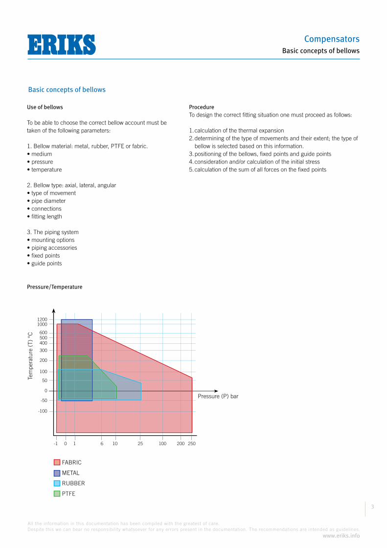
Pressure/Temperature
ProcedureTo design the correct fitting situation one must proceed as follows:
1. calculation of the thermal expansion2. determining of the type of movements and their extent; the type of
bellow is selected based on this information.3. positioning of the bellows, fixed points and guide points4. consideration and/or calculation of the initial stress5. calculation of the sum of all forces on the fixed points
12001000
300
200
100
50
0
-50
-100
600500400
-1 0 1 6 10 25 100 200 250
Pressure (P) bar
Tem
pera
ture
(T)
°C
FABRIC
METAL
RUBBER
PTFE
Hoses and Accessories
4
All the information in this documentation has been compiled with the greatest of care.
Despite this we can bear no responsibility whatsoever for any errors present in the documentation. The recommendations are intended as guidelines.
www.eriks.info
Basic concepts of bellows
Basic concepts of bellows
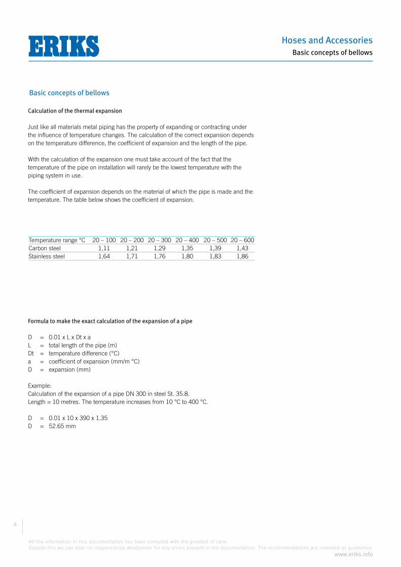
Calculation of the thermal expansion
Just like all materials metal piping has the property of expanding or contracting under the influence of temperature changes. The calculation of the correct expansion depends on the temperature difference, the coefficient of expansion and the length of the pipe.
With the calculation of the expansion one must take account of the fact that the temperature of the pipe on installation will rarely be the lowest temperature with the piping system in use.
The coefficient of expansion depends on the material of which the pipe is made and the temperature. The table below shows the coefficient of expansion.
Formula to make the exact calculation of the expansion of a pipe
D = 0.01 x L x Dt x aL = total length of the pipe (m)Dt = temperature difference (°C)a = coefficient of expansion (mm/m °C) D = expansion (mm)
Example:Calculation of the expansion of a pipe DN 300 in steel St. 35.8.Length = 10 metres. The temperature increases from 10 °C to 400 °C.
D = 0.01 x 10 x 390 x 1.35D = 52.65 mm
Temperature range °C 20 – 100 20 – 200 20 – 300 20 – 400 20 – 500 20 – 600Carbon steel 1,11 1,21 1,29 1,35 1,39 1,43Stainless steel 1,64 1,71 1,76 1,80 1,83 1,86
Compensators
5
All the information in this documentation has been compiled with the greatest of care.
Despite this we can bear no responsibility whatsoever for any errors present in the documentation. The recommendations are intended as guidelines.
www.eriks.info
Basic concepts of bellows
Basic concepts of bellows
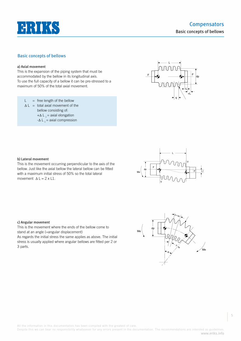
a) Axial movementThis is the expansion of the piping system that must be accommodated by the bellow in its longitudinal axis.To use the full capacity of a bellow it can be pre-stressed to a maximum of 50% of the total axial movement.
b) Lateral movementThis is the movement occurring perpendicular to the axis of the bellow. Just like the axial bellow the lateral bellow can be fitted with a maximum initial stress of 50% so the total lateral movement L = 2 x L1.
c) Angular movementThis is the movement where the ends of the bellow come to stand at an angle (=angular displacement)As regards the initial stress the same applies as above. The initial stress is usually applied where angular bellows are fitted per 2 or 3 parts.
L
Fdp
+L
-L
q
F
dpMe
F
F
L
L1
V
V
dpMe
Me
q + eø
e
q - eø
L = free length of the bellow L = total axial movement of the
bellow consisting of: + L 1 = axial elongation - L 1 = axial compression

Hoses and Accessories
6
All the information in this documentation has been compiled with the greatest of care.
Despite this we can bear no responsibility whatsoever for any errors present in the documentation. The recommendations are intended as guidelines.
www.eriks.info
Basic concepts of bellows
Basic concepts of bellows
Positioning of the bellows, fixed points and guide pointsThe piping system in which bellows are fitted must be ended by fixed points. These fixed points must be firm enough to accommodate the reactive forces of the bellow and the frictional resistance of the guide points. The fixed points and guide points must be such that the bellow does not have to bear the weight of the piping.
Positioning of the bellow
For small diameters For larger diameters
Fixed pointsFixed points must be provided:
accommodated by a number of bellows
Examples:
Distance L: depending on pressure, temperature and diameter approx. 75 to 100 times the NW.
as small as possible
fixed point fixed point 1st guide point 2nd guide point next guide points
4 x NW 14 x NW L L
NW

Compensators
7
All the information in this documentation has been compiled with the greatest of care.
Despite this we can bear no responsibility whatsoever for any errors present in the documentation. The recommendations are intended as guidelines.
www.eriks.info
Basic concepts of bellows
Basic concepts of bellows
Guide pointsGuide points are applied to ensure the correct alignment of the piping.
Examples:
Consideration and/or calculation of the initial stressIn many applications the fitting of bellows with a certain initial stress is appropriate. Besides a possible longer working life or lower reactive force, the movement reach of the bellow increases.
The assembly of a bellow with initial stress entails the bellow being fitted in such a way that the position in cold state is opposite to the expected expansion. In use the bellow returns to the neutral position and can then possibly be further compressed.
The maximum initial stress is irrespective of the type of bellow based on 50%of the total movement absorption. With the calculation of the initial stress it is important to besides the difference between installation and operating temperature also take account of the difference between the installation and minimum temperature.For example if the pipe is to be used in freezing weather outside.
Band guide points with or without rollers
T-guides
Tubular guides
Hoses and Accessories
8
All the information in this documentation has been compiled with the greatest of care.
Despite this we can bear no responsibility whatsoever for any errors present in the documentation. The recommendations are intended as guidelines.
www.eriks.info
Basic concepts of bellows
Basic concepts of bellows
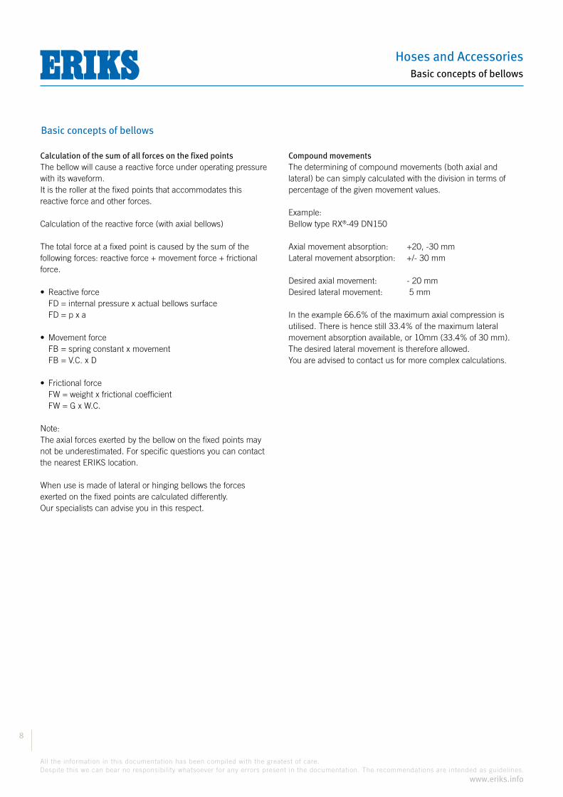
Calculation of the sum of all forces on the fixed pointsThe bellow will cause a reactive force under operating pressure with its waveform.It is the roller at the fixed points that accommodates this reactive force and other forces.
Calculation of the reactive force (with axial bellows)
The total force at a fixed point is caused by the sum of the following forces: reactive force + movement force + frictional force.
FD = internal pressure x actual bellows surface FD = p x a
FB = spring constant x movement FB = V.C. x D
FW = weight x frictional coefficient FW = G x W.C.
Note:The axial forces exerted by the bellow on the fixed points may not be underestimated. For specific questions you can contact the nearest ERIKS location.
When use is made of lateral or hinging bellows the forces exerted on the fixed points are calculated differently. Our specialists can advise you in this respect.
Compound movementsThe determining of compound movements (both axial and lateral) be can simply calculated with the division in terms of percentage of the given movement values.
Example:®-49 DN150
Axial movement absorption: +20, -30 mmLateral movement absorption: +/- 30 mm
Desired axial movement: - 20 mmDesired lateral movement: 5 mm
In the example 66.6% of the maximum axial compression is utilised. There is hence still 33.4% of the maximum lateral movement absorption available, or 10mm (33.4% of 30 mm). The desired lateral movement is therefore allowed.You are advised to contact us for more complex calculations.

Compensators
9
All the information in this documentation has been compiled with the greatest of care.
Despite this we can bear no responsibility whatsoever for any errors present in the documentation. The recommendations are intended as guidelines.
www.eriks.info
Basic concepts of bellows
Basic concepts of bellows
Working life of bellowsFor rubber, PTFE, and fabric bellows it is not possible to stipulate an exact working life because there are too many external and mechanical factors that can influence the working life and aging.
For metal bellows it is possible to calculate a working life.The working life of metal bellows is expressed in cycles.The working life of a metal bellow is accordingly equal to the total number of times the bellow makes a movement.
The figure depends on the actually used movement capacity with respect to the maximum permitted movement capacity as indicated in the table below.
Table: working life of bellows
Total number Effectively used % Working life desired cycles of the maximum factor N1 movement capacity 500 120 1,2 1000 100 1,0 2000 85 0,85 3000 77 0,77 5000 68 0,68 8000 61 0,61 10000 58 0,58 30000 44 0,44 50000 39 0,39 100000 33 0,33 200000 28 0,28 1000000 19 0,19
® metal bellows have a standard working life of 1,000 cycles.

Hoses and Accessories
10
All the information in this documentation has been compiled with the greatest of care.
Despite this we can bear no responsibility whatsoever for any errors present in the documentation. The recommendations are intended as guidelines.
www.eriks.info
Basic concepts of bellows
Basic concepts of bellows - application examples
Application of single bellows
Fig. 1Setup for small axial movements.
Fig. 2Setup to absorb an axial piping expansion. Pay attention to the applicationof the ‘intermediate’ fixed point (IA) in combination with the 2 fixed points (MA).As a result the pipe is divided into 2 separate expanding sections so there is each time 1 bellow between 2 fixed points.
Fig. 3Setup of bellows and guide points to accommodate axial length changes in a pipe with a branch.
Fig. 4Setup of bellows to accommodate axial length changes in a pipe with a larger diameter changing to a smaller diameter. Because of the difference in bellow diameter the difference in reactive force as a result of the process pressure must be accommodated with a fixed point between the bellows.
Fig. 5Shows a typical application of a single bellow to accommodate a combination of axial movements and lateral movements. In the pipe the one bend piece is anchored fixed (mA) while the other bend piece (DMA) can slide in one direction. The most important task of the bellow when fitted in the long piece of piping is the accommodation of axial movement.
MA
MAG1 G2 G G
MA
MAG G G2 G1 G2G1 G GIA
MAG G G G
MAMA
G1G2
G2 G1 G2G1
MAG G
MA
MA
G GG1 G2G1G2
DMA
MA
GGG2G1
IA
Fig. 1
Fig. 2
Fig. 3
Fig. 4
Fig. 5
Compensators
11
All the information in this documentation has been compiled with the greatest of care.
Despite this we can bear no responsibility whatsoever for any errors present in the documentation. The recommendations are intended as guidelines.
www.eriks.info
Basic concepts of bellows
Basic concepts of bellows - application examples
Application of single bellows
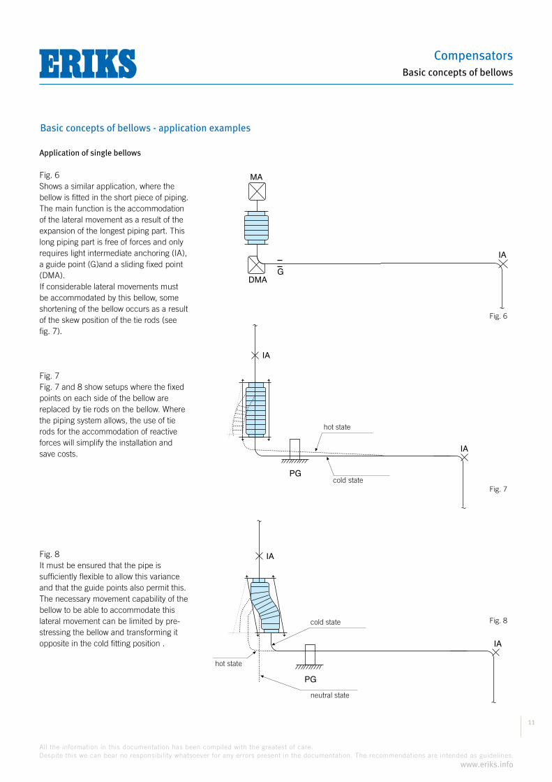
Fig. 6Shows a similar application, where the bellow is fitted in the short piece of piping. The main function is the accommodation of the lateral movement as a result of the expansion of the longest piping part. This long piping part is free of forces and only requires light intermediate anchoring (IA), a guide point (G)and a sliding fixed point (DMA).If considerable lateral movements must be accommodated by this bellow, some shortening of the bellow occurs as a result of the skew position of the tie rods (see fig. 7).
Fig. 7Fig. 7 and 8 show setups where the fixed points on each side of the bellow are replaced by tie rods on the bellow. Where the piping system allows, the use of tie rods for the accommodation of reactive forces will simplify the installation and save costs.
Fig. 8It must be ensured that the pipe is sufficiently flexible to allow this variance and that the guide points also permit this. The necessary movement capability of the bellow to be able to accommodate this lateral movement can be limited by pre-stressing the bellow and transforming it opposite in the cold fitting position .
DMAG
IA
MA
Fig. 6
Fig. 7
hot state
cold state
Fig. 8
hot state
cold state
neutral state

Hoses and Accessories
12
All the information in this documentation has been compiled with the greatest of care.
Despite this we can bear no responsibility whatsoever for any errors present in the documentation. The recommendations are intended as guidelines.
www.eriks.info
Basic concepts of bellows
Basic concepts of bellows - application examples
Application of lateral bellows
The bellow consists of two single bellows connected to each other with a piece of piping.
Fig. 9A customary application of the lateral bellow is fitting in a 90° bend arrangement. The tie rods accommodate the reactive force as a result of the process pressure. Even better is the setup in fig. 14 with hinging bellows to also accommodate the bending movement in the pipe.
Fig. 10In cases where a lateral bellow must compensate an axial movement other than its own thermal expansion, this can function as an axially limited bellow providing it is used in combination with 2 main anchors to accommodate reactive forces.
Fig. 11In cases where the bellow is very long with respect to its diameter, where a large number of waves is used on each end of the bellow or when the bellow is exposed to external loads such as wind forces, vibrations, etc., it can be necessary for limiting to be built into the bellow. This is to limit excessive movement of the bellows and the relatively freely suspended piece of piping in between. Fig. 11 A and B show two examples of the movement limiting of tie rods.
IA
IA
PG
PG Fig. 9
A B Fig. 11
procesvat
procesvat
Fig. 10
processvessel
processvessel

Compensators
13
All the information in this documentation has been compiled with the greatest of care.
Despite this we can bear no responsibility whatsoever for any errors present in the documentation. The recommendations are intended as guidelines.
www.eriks.info
Basic concepts of bellows
Basic concepts of bellows - application examples
Hinging bellows
Hinging bellows are usually used in sets of 2 or 3 at the same time to accommodate lateral movements in the same plane. With a hinging bellow the reactive force is accommodated by the hinge construction so only the necessary bending force is absorbed by the piping system.
Fig. 12Shows the use of a 2-hinge system to accommodate the thermal expansion in a flat Z-bend.
Fig. 13Shows a 2-hinge system with approximately the same effect as with the balanced bellow. In this case the bellow only accommodates the difference in length expansion between the pipe and the upper part of the process vessel.
Fig. 14Shows the application of 3-hinge bellows in one plane where the pipe is not flexible enough to accommodate the sagging of the pipe as occurs with a 2-hinge system, or where the transverse forces occurring with such sagging are too great for the connections to the equipment.The extra hinging bellow compensates the bending movement.The thermal pipe expansion is compensated by bellows A and B.
Fig. 15Shows the principle where hinging bellows are used in other than 90° bends.
IA
IA
PG
PG
Fig. 12
IA
IA
PG
PG
G
CB
A
Fig. 14
IA
IA G PG
Fig. 15
IA
PGproces
vat
Fig. 13
processvessel
Hoses and Accessories
14
All the information in this documentation has been compiled with the greatest of care.
Despite this we can bear no responsibility whatsoever for any errors present in the documentation. The recommendations are intended as guidelines.
www.eriks.info
Basic concepts of bellows
Basic concepts of bellows - application examples
Application of universal bellows
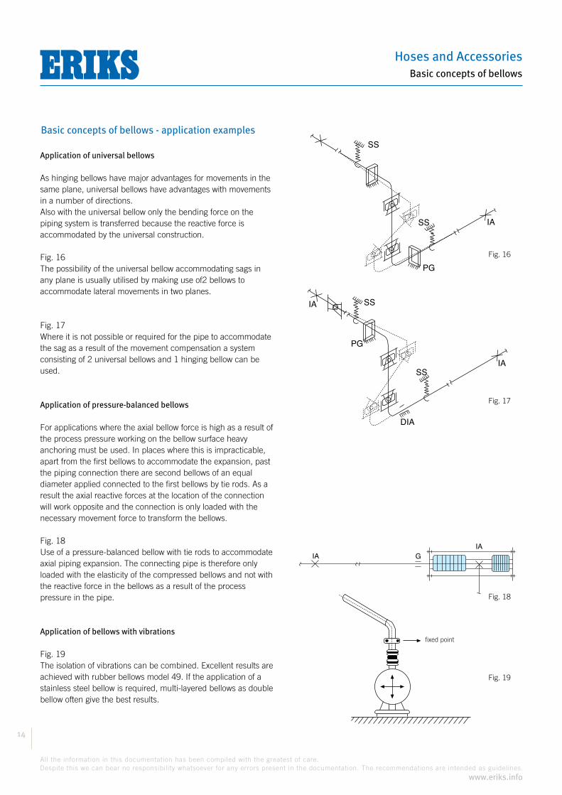
As hinging bellows have major advantages for movements in the same plane, universal bellows have advantages with movements in a number of directions.Also with the universal bellow only the bending force on the piping system is transferred because the reactive force is accommodated by the universal construction.
Fig. 16The possibility of the universal bellow accommodating sags in any plane is usually utilised by making use of2 bellows to accommodate lateral movements in two planes.
Fig. 17Where it is not possible or required for the pipe to accommodate the sag as a result of the movement compensation a system consisting of 2 universal bellows and 1 hinging bellow can be used.
Application of pressure-balanced bellows
For applications where the axial bellow force is high as a result of the process pressure working on the bellow surface heavy anchoring must be used. In places where this is impracticable, apart from the first bellows to accommodate the expansion, past the piping connection there are second bellows of an equal diameter applied connected to the first bellows by tie rods. As a result the axial reactive forces at the location of the connection will work opposite and the connection is only loaded with the necessary movement force to transform the bellows.
Fig. 18Use of a pressure-balanced bellow with tie rods to accommodate axial piping expansion. The connecting pipe is therefore only loaded with the elasticity of the compressed bellows and not with the reactive force in the bellows as a result of the process pressure in the pipe.
Application of bellows with vibrations
Fig. 19The isolation of vibrations can be combined. Excellent results are achieved with rubber bellows model 49. If the application of a stainless steel bellow is required, multi-layered bellows as double bellow often give the best results.
SS
SS
PG
IA
Fig. 16
SS
SS
DIA
IA
PG
IA
Fig. 17
GIAIA
Fig. 18
vast punt
Fig. 19
fixed point
Compensators
15
All the information in this documentation has been compiled with the greatest of care.
Despite this we can bear no responsibility whatsoever for any errors present in the documentation. The recommendations are intended as guidelines.
www.eriks.info
Basic concepts of bellows
Basic concepts of bellows - application examples
Important points when installing bellows
1. Fit axial bellows preferably as close as possible to a main anchor point on the pipe.
2. Maximum distance between the guide points of the pipe may not exceed the table values.
3. Assembly of the bellows with correct initial stress must be insured.
4. Accurate alignment of flanges with respect to each other or the piping ends.
5. There may be no torsion forces on the bellows.
6. Parts of bellows such as hinges or tie rods are not fixed points or anchors but do impede movements if the anchoring fails.
7. Liners applied inside assist an even flow and reduce flow wear.
8. Exterior protective covers prevent the outside of the bellow from damage and can be used to support insulating material (only with metal bellows).
Hoses and Accessories
16
All the information in this documentation has been compiled with the greatest of care.
Despite this we can bear no responsibility whatsoever for any errors present in the documentation. The recommendations are intended as guidelines.
www.eriks.info
Rubber bellows
Rubber bellows - assembly instructions
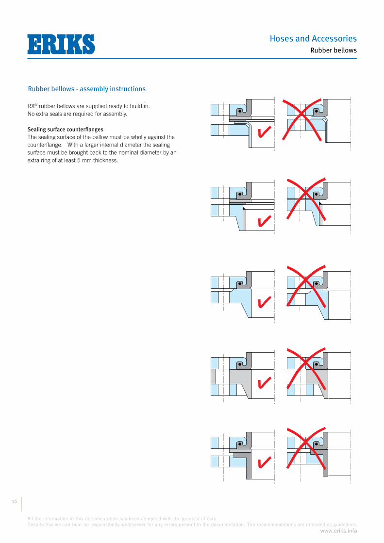
® rubber bellows are supplied ready to build in. No extra seals are required for assembly.
Sealing surface counterflangesThe sealing surface of the bellow must be wholly against the counterflange. With a larger internal diameter the sealing surface must be brought back to the nominal diameter by an extra ring of at least 5 mm thickness.

Compensators
17
All the information in this documentation has been compiled with the greatest of care.
Despite this we can bear no responsibility whatsoever for any errors present in the documentation. The recommendations are intended as guidelines.
www.eriks.info
Rubber bellows
Rubber bellows - assembly instructions
Fitting the bolts
Type RX® 48, RX® 50, RX® 51 and RX® 55The bolt head must be inserted on the bellows side through the bolt holes.
Type RX® 49The bolt head must be inserted on the counterflange side in the bolt holes. Protruding bolts (too long) must be avoided. These can damage the bellows.
Torques of boltsBolts must be tightened in 3 stages.
Step 1:Evenly tighten all bolts by hand. Ensure the parallelism of the sealing surface.
Step 2:Tighten the bolts crosswise as in the adjacent table. With a working pressure of
® 49) these values must be increased by 30%.
Step 3:After waiting 30 minutes tighten the bolts as in the adjacent table.Further tightening of the bolts is not recommended. This can cause damage to the rubber sealing surface.
Table: Torques of bolts
DN Step 2 Step 3 20-80 50 Nm 80 Nm 100-300 50 Nm 100 Nm 350-500 50 Nm 130 Nm 600 100 Nm 210 Nm 700 100 Nm 250 Nm 750 100 Nm 280 Nm 800 100 Nm 300 Nm 900 100 Nm 310 Nm 1000 100 Nm 340 Nm

Hoses and Accessories
18
All the information in this documentation has been compiled with the greatest of care.
Despite this we can bear no responsibility whatsoever for any errors present in the documentation. The recommendations are intended as guidelines.
www.eriks.info
Rubber bellows
Rubber bellows - assembly instructions
Assembly instructions for rubber bellows type RX® 46® 46 have thread connections.
The thread connection must always be tightened with two spanners to avoid twisting the rubber bellows.
Important:
rubber bellows with fast aging as a consequence.
assembly the bellow is preferably fitted with an initial stress.
limiters.
Advantages of RX® rubber bellows:
For bellows DN20 and DN25The front insert part is held with the spanner and the union nut turned on the bellow.
For bellows DN32 and DN50The rear insert part is held with the spanner and the union nut tightened on the bellow.
Compensators
19
All the information in this documentation has been compiled with the greatest of care.
Despite this we can bear no responsibility whatsoever for any errors present in the documentation. The recommendations are intended as guidelines.
www.eriks.info
Rubber bellows
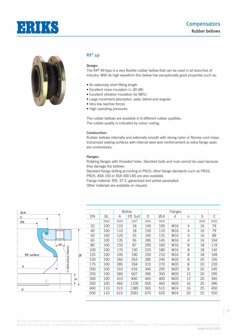
RX® 49
Bellow Flanges DN BL A Eff. Surf. D ØLK d n S C mm mm cm2 mm mm mm mm 32 100 110 18 140 100 M16 4 16 79 40 100 110 18 150 110 M16 4 16 79 50 100 120 35 165 125 M16 4 16 89 65 100 135 56 185 145 M16 4 16 104 80 100 150 87 200 160 M16 8 18 119 100 100 170 130 220 180 M16 8 18 142 125 100 195 190 250 210 M16 8 18 169 150 100 260 263 285 240 M20 8 20 195 175 100 285 334 315 270 M20 8 20 220 200 100 310 416 340 295 M20 8 20 245 250 100 360 607 395 350 M20 12 20 295 300 100 410 830 445 400 M20 12 20 345 350 100 460 1100 505 460 M20 16 20 396 400 110 515 1385 565 515 M24 16 25 450 500 110 615 2091 670 620 M24 20 25 550
Eff. surface
number of bolt holes
n
S
BL
ød
A
D
DN
C
ØLK
Design:® 49 type is a very flexible rubber bellow that can be used in all branches of
industry. With its high waveform this bellow has exceptionally good properties such as:
The rubber bellows are available in 6 different rubber qualities.The rubber quality is indicated by colour coding.
Construction:Rubber bellows internally and externally smooth with strong nylon or Nomex cord inlays.Vulcanised sealing surfaces with internal steel wire reinforcement so extra flange seals are unnecessary.
Flanges:Rotating flanges with threaded holes. Standard bolts and nuts cannot be used because they damage the bellows.Standard flange drilling according to PN10, other flange standards such as PN16, PN25, ASA 150 or ASA 300 LBS are also available.Flange material: RSt. 37-2, galvanised and yellow passivated.Other materials are available on request.

Hoses and Accessories
20
All the information in this documentation has been compiled with the greatest of care.
Despite this we can bear no responsibility whatsoever for any errors present in the documentation. The recommendations are intended as guidelines.
www.eriks.info
Rubber bellows
RX® 49
Vacuum support rings:® 49 are suitable for applications underpressure. However, to prevent the
bellows from being drawn in, from 20% vacuum the fitting of a vacuum support ring is required.Material types: Stainless steel (standard), Inconel, Hastelloy, etc.
Movement limiters/tie rods:A bellow is a flexible element that under pressure will try to push the pipe away in an axial direction. This is called the reactive force. One must therefore take account of this with the construction of the piping, and provide the piping with the necessary guide points and fixed points. If a bellow is fitted with the intention of insulating vibrations, the reactive force can be accommodated by tie rods in rubber bushes.There are two designs of movement limiters available as standard:
BL BL
Design B Design C

Compensators
21
All the information in this documentation has been compiled with the greatest of care.
Despite this we can bear no responsibility whatsoever for any errors present in the documentation. The recommendations are intended as guidelines.
www.eriks.info
Rubber bellows
RX® 49 blue
Application:
(also drinking water)
and ketones
Interior material bellows: IIR, black
Material inlays: nylon
Exterior material bellows:EPDM, black with blue rubber label marking
Temperature and pressure resistance:
Design with round flanges
Movement absorption
mm + mm - mm +/- mm +/- °10040089 32 100 20 30 30 710040090 40 100 20 30 30 710040091 50 100 20 30 30 710040092 65 100 20 30 30 710040093 80 100 20 30 30 710040094 100 100 20 30 30 710040095 125 100 20 30 30 710040096 150 100 20 30 30 710040097 175 100 20 30 30 710040098 200 100 20 30 30 710040099 250 100 20 30 30 710040100 300 100 20 30 30 710040101 350 100 20 30 30 710040102 400 110 20 30 30 710040103 500 110 20 30 30 7
Design with movement limiters - design C
Movement absorption
mm + mm - mm +/- mm +/- °10040104 32 100 20 30 30 710040105 40 100 20 30 30 710040106 50 100 20 30 30 710040107 65 100 20 30 30 710040108 80 100 20 30 30 710040109 100 100 20 30 30 710040110 125 100 20 30 30 710040111 150 100 20 30 30 710040112 175 100 20 30 30 710040113 200 100 20 30 30 710040114 250 100 20 30 30 710040115 300 100 20 30 30 710040116 350 100 20 30 30 710040117 400 110 20 30 30 710040118 500 110 20 30 30 7
The permissible movement capacity isdependent on the medium temperature: Temperature: Movement capacity:
up to 50 °C 100% up to 70 °C 80% up to 90 °C 70%
Hoses and Accessories
22
All the information in this documentation has been compiled with the greatest of care.
Despite this we can bear no responsibility whatsoever for any errors present in the documentation. The recommendations are intended as guidelines.
www.eriks.info
Rubber bellows
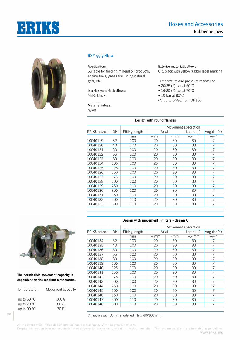
RX® 49 yellow
The permissible movement capacity isdependent on the medium temperature: Temperature: Movement capacity:
up to 50 °C 100% up to 70 °C 80% up to 90 °C 70%
Application:Suitable for feeding mineral oil products, engine fuels, gases (including natural gas), etc.
Interior material bellows:NBR, black
Material inlays:nylon
Exterior material bellows:CR, black with yellow rubber label marking
Temperature and pressure resistance:
Design with round flanges
Movement absorption
mm + mm - mm +/- mm +/- °10040119 32 100 20 30 30 710040120 40 100 20 30 30 710040121 50 100 20 30 30 710040122 65 100 20 30 30 710040123 80 100 20 30 30 710040124 100 100 20 30 30 710040125 125 100 20 30 30 710040126 150 100 20 30 30 710040127 175 100 20 30 30 710040128 200 100 20 30 30 710040129 250 100 20 30 30 710040130 300 100 20 30 30 710040131 350 100 20 30 30 710040132 400 110 20 30 30 710040133 500 110 20 30 30 7
Design with movement limiters - design C
Movement absorption
mm + mm - mm +/- mm +/- °10040134 32 100 20 30 30 710040135 40 100 20 30 30 710040136 50 100 20 30 30 710040137 65 100 20 30 30 710040138 80 100 20 30 30 710040139 100 100 20 30 30 710040140 125 100 20 30 30 710040141 150 100 20 30 30 710040142 175 100 20 30 30 710040143 200 100 20 30 30 710040144 250 100 20 30 30 710040145 300 100 20 30 30 710040146 350 100 20 30 30 710040147 400 110 20 30 30 710040148 500 110 20 30 30 7

Compensators
23
All the information in this documentation has been compiled with the greatest of care.
Despite this we can bear no responsibility whatsoever for any errors present in the documentation. The recommendations are intended as guidelines.
www.eriks.info
Rubber bellows
RX® 49 green
The permissible movement capacity isdependent on the medium temperature: Temperature: Movement capacity:
up to 50 °C 100% up to 70 °C 80% up to 90 °C 70%
Design with round flanges
Movement absorption
mm + mm - mm +/- mm +/- °10040149 32 100 20 30 30 710040150 40 100 20 30 30 710040151 50 100 20 30 30 710040152 65 100 20 30 30 710040153 80 100 20 30 30 710040154 100 100 20 30 30 710040155 125 100 20 30 30 710040156 150 100 20 30 30 710040157 175 100 20 30 30 710040158 200 100 20 30 30 710040159 250 100 20 30 30 710040160 300 100 20 30 30 710040161 350 100 20 30 30 710040162 400 110 20 30 30 710040163 500 110 20 30 30 7
Design with movement limiters - design C
Movement absorption
mm + mm - mm +/- mm +/- °10040164 32 100 20 30 30 710040165 40 100 20 30 30 710040166 50 100 20 30 30 710040167 65 100 20 30 30 710040168 80 100 20 30 30 710040169 100 100 20 30 30 710040170 125 100 20 30 30 710040171 150 100 20 30 30 710040172 175 100 20 30 30 710040173 200 100 20 30 30 710040174 250 100 20 30 30 710040175 300 100 20 30 30 710040176 350 100 20 30 30 710040177 400 110 20 30 30 710040178 500 110 20 30 30 7
Application:
ERIKS for advice
on the medium
Interior material bellows: CSM, black
Material inlays: nylon
Exterior material bellows:CSM, black with green rubber label marking
Temperature and pressure resistance:
Hoses and Accessories
24
All the information in this documentation has been compiled with the greatest of care.
Despite this we can bear no responsibility whatsoever for any errors present in the documentation. The recommendations are intended as guidelines.
www.eriks.info
Rubber bellows
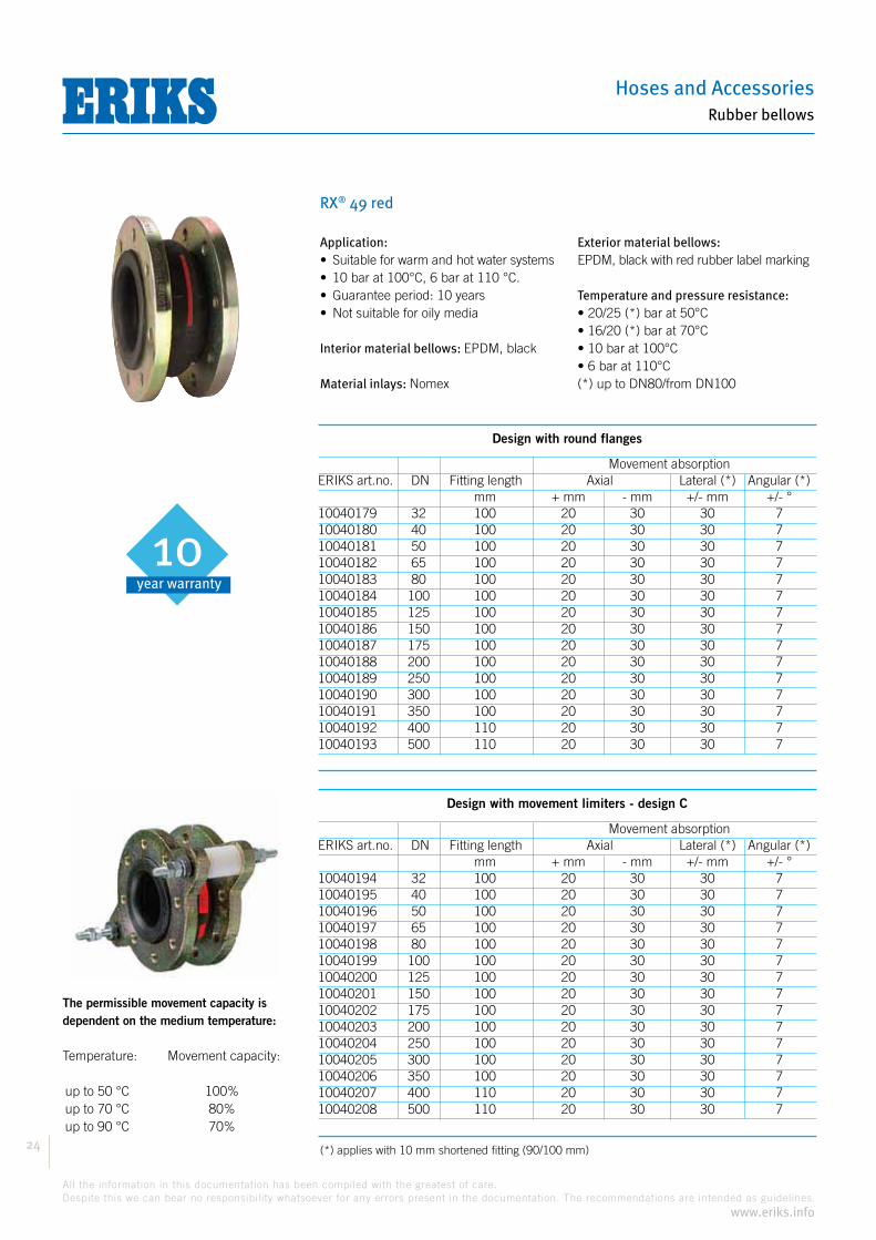
RX® 49 red
The permissible movement capacity isdependent on the medium temperature: Temperature: Movement capacity:
up to 50 °C 100% up to 70 °C 80% up to 90 °C 70%
Design with round flanges
Movement absorption
mm + mm - mm +/- mm +/- °10040179 32 100 20 30 30 710040180 40 100 20 30 30 710040181 50 100 20 30 30 710040182 65 100 20 30 30 710040183 80 100 20 30 30 710040184 100 100 20 30 30 710040185 125 100 20 30 30 710040186 150 100 20 30 30 710040187 175 100 20 30 30 710040188 200 100 20 30 30 710040189 250 100 20 30 30 710040190 300 100 20 30 30 710040191 350 100 20 30 30 710040192 400 110 20 30 30 710040193 500 110 20 30 30 7
Design with movement limiters - design C
Movement absorption
mm + mm - mm +/- mm +/- °10040194 32 100 20 30 30 710040195 40 100 20 30 30 710040196 50 100 20 30 30 710040197 65 100 20 30 30 710040198 80 100 20 30 30 710040199 100 100 20 30 30 710040200 125 100 20 30 30 710040201 150 100 20 30 30 710040202 175 100 20 30 30 710040203 200 100 20 30 30 710040204 250 100 20 30 30 710040205 300 100 20 30 30 710040206 350 100 20 30 30 710040207 400 110 20 30 30 710040208 500 110 20 30 30 7
Application:
Interior material bellows: EPDM, black
Material inlays: Nomex
Exterior material bellows:EPDM, black with red rubber label marking
Temperature and pressure resistance:
year warranty
10

Compensators
25
All the information in this documentation has been compiled with the greatest of care.
Despite this we can bear no responsibility whatsoever for any errors present in the documentation. The recommendations are intended as guidelines.
www.eriks.info
Rubber bellows
RX® 49 white
The permissible movement capacity isdependent on the medium temperature: Temperature: Movement capacity:
up to 50 °C 100% up to 70 °C 80% up to 90 °C 70%
Design with round flanges
Movement absorption
mm + mm - mm +/- mm +/- °10040209 32 100 20 30 30 710040210 40 100 20 30 30 710040211 50 100 20 30 30 710040212 65 100 20 30 30 710040213 80 100 20 30 30 710040214 100 100 20 30 30 710040215 125 100 20 30 30 710040216 150 100 20 30 30 710040217 175 100 20 30 30 710040218 200 100 20 30 30 710040219 250 100 20 30 30 710040220 300 100 20 30 30 710040221 350 100 20 30 30 710040222 400 110 20 30 30 710040223 500 110 20 30 30 7
Design with movement limiters - design C
Movement absorption
mm + mm - mm +/- mm +/- °10040224 32 100 20 30 30 710040225 40 100 20 30 30 710040226 50 100 20 30 30 710040227 65 100 20 30 30 710040228 80 100 20 30 30 710040229 100 100 20 30 30 710040230 125 100 20 30 30 710040231 150 100 20 30 30 710040232 175 100 20 30 30 710040233 200 100 20 30 30 710040234 250 100 20 30 30 710040235 300 100 20 30 30 710040236 350 100 20 30 30 710040237 400 110 20 30 30 710040238 500 110 20 30 30 7
Application:
oils and fats fruit juices, soft drinks, etc.
RAL-C53
Interior material bellows: NBR, white
Material inlays: nylon
Exterior material bellows:CR, black with white rubber label marking
Temperature and pressure resistance:
Hoses and Accessories
26
All the information in this documentation has been compiled with the greatest of care.
Despite this we can bear no responsibility whatsoever for any errors present in the documentation. The recommendations are intended as guidelines.
www.eriks.info
Rubber bellows
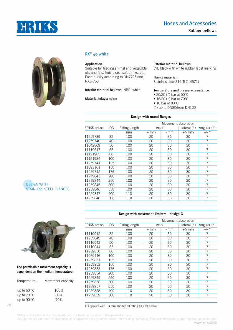
RX® 49 white
The permissible movement capacity isdependent on the medium temperature: Temperature: Movement capacity:
up to 50 °C 100% up to 70 °C 80% up to 90 °C 70%
Design with round flanges
Movement absorption
mm + mm - mm +/- mm +/- °11259739 32 100 20 30 30 711259740 40 100 20 30 30 711042809 50 100 20 30 30 711119647 65 100 20 30 30 711121985 80 100 20 30 30 711121984 100 100 20 30 30 711259741 125 100 20 30 30 711093101 150 100 20 30 30 711259742 175 100 20 30 30 711259843 200 100 20 30 30 711259844 250 100 20 30 30 711259845 300 100 20 30 30 711259846 350 100 20 30 30 711259847 400 110 20 30 30 711259848 500 110 20 30 30 7
Design with movement limiters - design C
Movement absorption
mm + mm - mm +/- mm +/- °11110012 32 100 20 30 30 711259849 40 100 20 30 30 711110043 50 100 20 30 30 711110044 65 100 20 30 30 711259850 80 100 20 30 30 711079446 100 100 20 30 30 711259851 125 100 20 30 30 711259852 150 100 20 30 30 711259853 175 100 20 30 30 711259854 200 100 20 30 30 711259855 250 100 20 30 30 711259856 300 100 20 30 30 711259857 350 100 20 30 30 711259858 400 110 20 30 30 711259859 500 110 20 30 30 7
Application:Suitable for feeding animal and vegetable oils and fats, fruit juices, soft drinks, etc.Food quality according to DN7725 and RAL-C53
Interior material bellows: NBR, white
Material inlays: nylon
Exterior material bellows:CR, black with white rubber label marking
Flange material:Stainless steel 316 Ti (1.4571)
Temperature and pressure resistance:
DESIGN WITHSTAINLESS STEEL FLANGES

Compensators
27
All the information in this documentation has been compiled with the greatest of care.
Despite this we can bear no responsibility whatsoever for any errors present in the documentation. The recommendations are intended as guidelines.
www.eriks.info
Rubber bellows
RX® 49 black
The permissible movement capacity isdependent on the medium temperature: Temperature: Movement capacity:
up to 50 °C 100% up to 70 °C 80% up to 90 °C 70%
Design with round flanges
Movement absorption
mm + mm - mm +/- mm +/- °10040239 32 100 20 30 30 710040240 40 100 20 30 30 710040241 50 100 20 30 30 710040242 65 100 20 30 30 710040243 80 100 20 30 30 710040244 100 100 20 30 30 710040245 125 100 20 30 30 710040246 150 100 20 30 30 710040247 200 100 20 30 30 7
Design with movement limiters - design C
Movement absorption
mm + mm - mm +/- mm +/- °10040248 32 100 20 30 30 710040249 40 100 20 30 30 710040250 50 100 20 30 30 710040251 65 100 20 30 30 710040252 80 100 20 30 30 710040253 100 100 20 30 30 710040254 125 100 20 30 30 710040255 150 100 20 30 30 710040256 200 100 20 30 30 7
Application:
high pressures and temperatures than ® 49 blue.
Interior material bellows:IIR, black
Material inlays:nylon
Exterior material bellows:EPDM black
Temperature and pressure resistance:
Hoses and Accessories
28
All the information in this documentation has been compiled with the greatest of care.
Despite this we can bear no responsibility whatsoever for any errors present in the documentation. The recommendations are intended as guidelines.
www.eriks.info
Rubber bellows
RX® 50
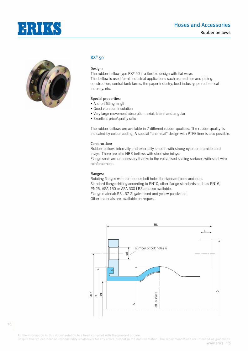
Design:® 50 is a flexible design with flat wave.
This bellow is used for all industrial applications such as machine and piping construction, central tank farms, the paper industry, food industry, petrochemical industry, etc.
Special properties:
The rubber bellows are available in 7 different rubber qualities. The rubber quality is indicated by colour coding. A special “chemical” design with PTFE liner is also possible.
Construction:Rubber bellows internally and externally smooth with strong nylon or aramide cord inlays. There are also NBR bellows with steel wire inlays.Flange seals are unnecessary thanks to the vulcanised sealing surfaces with steel wire reinforcement.
Flanges:Rotating flanges with continuous bolt holes for standard bolts and nuts.Standard flange drilling according to PN10, other flange standards such as PN16, PN25, ASA 150 or ASA 300 LBS are also available.Flange material: RSt. 37-2, galvanised and yellow passivated. Other materials are available on request.
Eff. opp.
aantal boutgaten n
S
BL
ød
A
D
DN
CØLK
eff.
surf
ace
number of bolt holes n

Compensators
29
All the information in this documentation has been compiled with the greatest of care.
Despite this we can bear no responsibility whatsoever for any errors present in the documentation. The recommendations are intended as guidelines.
www.eriks.info
Rubber bellows
RX® 50
Design B Design C
Data Table
Bellows Flanges DN BL A Eff. Surf. D ØLK d n S C mm mm cm2 mm mm mm mm 20 130 81 17 105 75 12 4 16 65 25 130 81 17 115 85 14 4 16 65 32 130 81 17 140 100 18 4 16 65 40 130 86 18 150 110 18 4 16 74 50 130 96 32 165 125 18 4 16 86 65 130 111 53 185 145 18 4 16 105 80 130 122 85 200 160 18 8 18 118 100 130 142 128 220 180 18 8 18 137 125 130 168 187 250 210 18 8 18 166 150 130 192 259 285 240 23 8 20 192 200 130 252 410 340 295 23 8 20 252 250 130 302 596 395 350 23 12 20 304 300 130 354 822 445 400 23 12 20 354 350 130 420 907 505 460 22 16 20 412 400 200 480 1018 565 515 26 16 25 470 500 200 580 1692 670 620 26 20 30 570 600 200 680 3078 780 725 30 20 30 675 700 250 800 4019 895 840 30 24 35 780 800 250 880 5436 1015 950 33 24 40 887 900 300 1038 6706 1115 1050 33 28 40 985 1000 300 1138 8231 1230 1160 36 28 40 1085
Vacuum support rings® 50 are suitable for applications underpressure. However, to prevent the
bellows from being drawn in, from 20% vacuum the fitting of a vacuum support ring is required. Material types: Stainless steel (standard), Inconel, Hastelloy, etc.
Movement limiters/tie rodsA bellow is a flexible element that under pressure will try to push the pipe away in an axial direction. This is called the reactive force. One must therefore take account of this with the construction of the piping, and provide the piping with the necessary guide points and fixed points. If a bellow is fitted with the intention of insulating vibrations, the reactive force can be accommodated by tie rods in rubber bushes.There are two designs of movement limiters available as standard:
BL BL
Hoses and Accessories
30
All the information in this documentation has been compiled with the greatest of care.
Despite this we can bear no responsibility whatsoever for any errors present in the documentation. The recommendations are intended as guidelines.
www.eriks.info
Rubber bellows
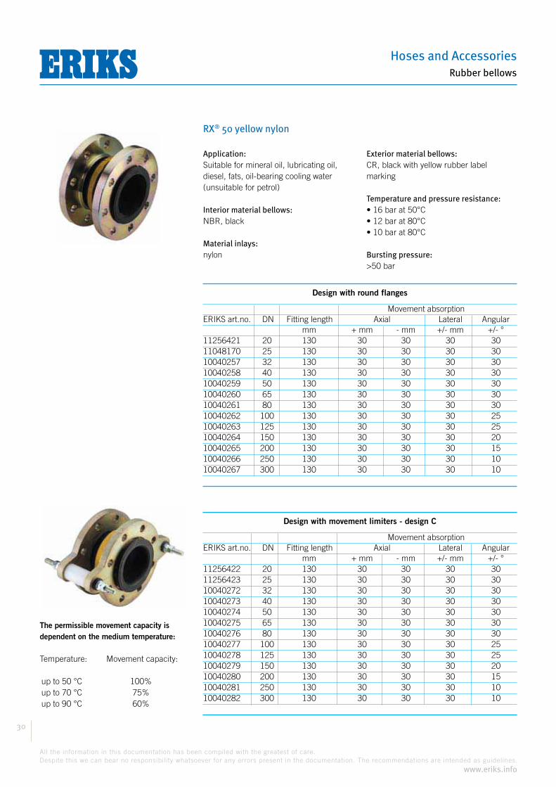
RX® 50 yellow nylon
The permissible movement capacity isdependent on the medium temperature: Temperature: Movement capacity:
up to 50 °C 100% up to 70 °C 75% up to 90 °C 60%
Application:Suitable for mineral oil, lubricating oil, diesel, fats, oil-bearing cooling water (unsuitable for petrol)
Interior material bellows:NBR, black
Material inlays:nylon
Exterior material bellows:CR, black with yellow rubber label marking
Temperature and pressure resistance:
Bursting pressure:
Design with round flanges
Movement absorptionERIKS art.no. DN Fitting length Axial Lateral Angular mm + mm - mm +/- mm +/- °11256421 20 130 30 30 30 3011048170 25 130 30 30 30 3010040257 32 130 30 30 30 3010040258 40 130 30 30 30 3010040259 50 130 30 30 30 3010040260 65 130 30 30 30 3010040261 80 130 30 30 30 3010040262 100 130 30 30 30 2510040263 125 130 30 30 30 2510040264 150 130 30 30 30 2010040265 200 130 30 30 30 1510040266 250 130 30 30 30 1010040267 300 130 30 30 30 10
Design with movement limiters - design C
Movement absorptionERIKS art.no. DN Fitting length Axial Lateral Angular mm + mm - mm +/- mm +/- °11256422 20 130 30 30 30 3011256423 25 130 30 30 30 3010040272 32 130 30 30 30 3010040273 40 130 30 30 30 3010040274 50 130 30 30 30 3010040275 65 130 30 30 30 3010040276 80 130 30 30 30 3010040277 100 130 30 30 30 2510040278 125 130 30 30 30 2510040279 150 130 30 30 30 2010040280 200 130 30 30 30 1510040281 250 130 30 30 30 1010040282 300 130 30 30 30 10

Compensators
31
All the information in this documentation has been compiled with the greatest of care.
Despite this we can bear no responsibility whatsoever for any errors present in the documentation. The recommendations are intended as guidelines.
www.eriks.info
Rubber bellows
RX® 50 yellow TW
The permissible movement capacity isdependent on the medium temperature: Temperature: Movement capacity:
up to 50 °C 100% up to 70 °C 75% up to 90 °C 60%
Note: this bellow is also available with alu-minium
Application:Suitable for petrol, diesel, heating oil, oil, lubricating oil and natural gas
Interior material bellows: NBR, black
Material inlays: nylon
Exterior material bellows:CR, black with yellow rubber label marking
Bursting pressure:
Design with round flanges
Movement absorptionERIKS art.no. DN Fitting length Axial Lateral Angular mm + mm - mm +/- mm +/- °11256446 20 130 30 30 30 3011256447 25 130 30 30 30 3011256448 32 130 30 30 30 3011256449 40 130 30 30 30 3011256450 50 130 30 30 30 3011256451 65 130 30 30 30 3011256452 80 130 30 30 30 3011256453 100 130 30 30 30 2511256454 125 130 30 30 30 2511256455 150 130 30 30 30 2011256456 200 130 30 30 30 1511256457 250 130 30 30 30 1011256458 300 130 30 30 30 1011051922 350 200 30 50 30 610040268 400 200 30 50 30 810040269 500 200 30 50 30 610040270 600 200 30 50 30 611256459 700 250 30 50 30 610040271 800 250 30 50 30 511256460 900 300 30 50 30 411256461 1000 300 30 50 30 4
Design with movement limiters - design C
Movement absorptionERIKS art.no. DN Fitting length Axial Lateral Angular mm + mm - mm +/- mm +/- °11256462 20 130 30 30 30 3011256463 25 130 30 30 30 3011256464 32 130 30 30 30 3011256465 40 130 30 30 30 3011256466 50 130 30 30 30 3011256467 65 130 30 30 30 3011256468 80 130 30 30 30 3011256469 100 130 30 30 30 2511256470 125 130 30 30 30 2511256471 150 130 30 30 30 2011256472 200 130 30 30 30 1511256473 250 130 30 30 30 1011256474 300 130 30 30 30 1011256475 350 200 30 50 30 610040283 400 200 30 50 30 810040284 500 200 30 50 30 611256476 600 200 30 50 30 611256477 700 250 30 50 30 611256478 800 250 30 50 30 511256479 900 300 30 50 30 411256480 1000 300 30 50 30 4
Temperature and pressure resistance:
DN20 up to and including DN400:
DN500 up to and including DN1000:
Hoses and Accessories
32
All the information in this documentation has been compiled with the greatest of care.
Despite this we can bear no responsibility whatsoever for any errors present in the documentation. The recommendations are intended as guidelines.
www.eriks.info
Rubber bellows
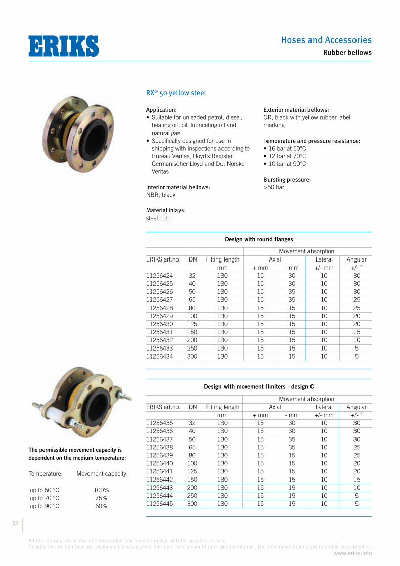
RX® 50 yellow steel
The permissible movement capacity isdependent on the medium temperature: Temperature: Movement capacity:
up to 50 °C 100% up to 70 °C 75% up to 90 °C 60%
Application:
heating oil, oil, lubricating oil and natural gas
shipping with inspections according to Bureau Veritas, Lloyd’s Register, Germanischer Lloyd and Det Norske Veritas
Interior material bellows:NBR, black
Material inlays:steel cord
Exterior material bellows:CR, black with yellow rubber label marking
Temperature and pressure resistance:
Bursting pressure:
Design with round flanges
Movement absorptionERIKS art.no. DN Fitting length Axial Lateral Angular mm + mm - mm +/- mm +/- °11256424 32 130 15 30 10 3011256425 40 130 15 30 10 3011256426 50 130 15 35 10 3011256427 65 130 15 35 10 2511256428 80 130 15 15 10 2511256429 100 130 15 15 10 2011256430 125 130 15 15 10 2011256431 150 130 15 15 10 1511256432 200 130 15 15 10 1011256433 250 130 15 15 10 511256434 300 130 15 15 10 5
Design with movement limiters - design C
Movement absorptionERIKS art.no. DN Fitting length Axial Lateral Angular mm + mm - mm +/- mm +/- °11256435 32 130 15 30 10 3011256436 40 130 15 30 10 3011256437 50 130 15 35 10 3011256438 65 130 15 35 10 2511256439 80 130 15 15 10 2511256440 100 130 15 15 10 2011256441 125 130 15 15 10 2011256442 150 130 15 15 10 1511256443 200 130 15 15 10 1011256444 250 130 15 15 10 511256445 300 130 15 15 10 5
Compensators
33
All the information in this documentation has been compiled with the greatest of care.
Despite this we can bear no responsibility whatsoever for any errors present in the documentation. The recommendations are intended as guidelines.
www.eriks.info
Rubber bellows
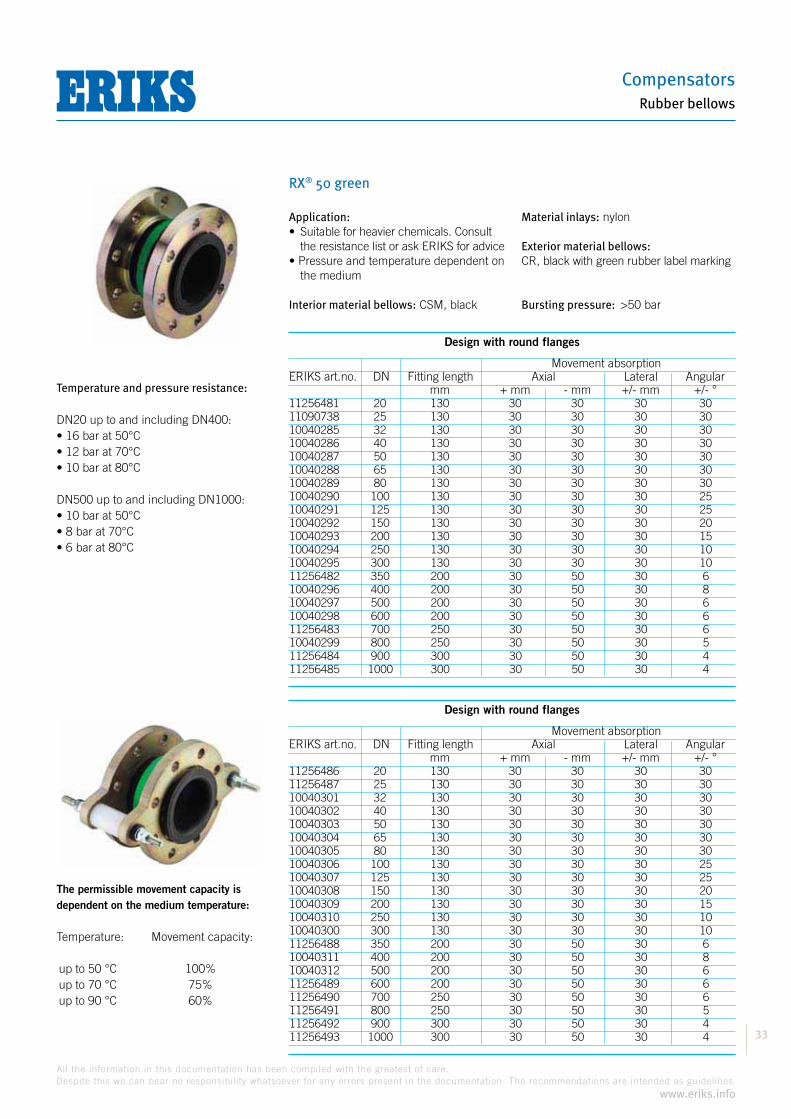
RX® 50 green
The permissible movement capacity isdependent on the medium temperature: Temperature: Movement capacity:
up to 50 °C 100% up to 70 °C 75% up to 90 °C 60%
Application:
the resistance list or ask ERIKS for advice
the medium
Interior material bellows: CSM, black
Material inlays: nylon
Exterior material bellows:CR, black with green rubber label marking
Bursting pressure:
Design with round flanges
Movement absorptionERIKS art.no. DN Fitting length Axial Lateral Angular mm + mm - mm +/- mm +/- °11256481 20 130 30 30 30 3011090738 25 130 30 30 30 3010040285 32 130 30 30 30 3010040286 40 130 30 30 30 3010040287 50 130 30 30 30 3010040288 65 130 30 30 30 3010040289 80 130 30 30 30 3010040290 100 130 30 30 30 2510040291 125 130 30 30 30 2510040292 150 130 30 30 30 2010040293 200 130 30 30 30 1510040294 250 130 30 30 30 1010040295 300 130 30 30 30 1011256482 350 200 30 50 30 610040296 400 200 30 50 30 810040297 500 200 30 50 30 610040298 600 200 30 50 30 611256483 700 250 30 50 30 610040299 800 250 30 50 30 511256484 900 300 30 50 30 411256485 1000 300 30 50 30 4
Design with round flanges
Movement absorptionERIKS art.no. DN Fitting length Axial Lateral Angular mm + mm - mm +/- mm +/- °11256486 20 130 30 30 30 3011256487 25 130 30 30 30 3010040301 32 130 30 30 30 3010040302 40 130 30 30 30 3010040303 50 130 30 30 30 3010040304 65 130 30 30 30 3010040305 80 130 30 30 30 3010040306 100 130 30 30 30 2510040307 125 130 30 30 30 2510040308 150 130 30 30 30 2010040309 200 130 30 30 30 1510040310 250 130 30 30 30 1010040300 300 130 30 30 30 1011256488 350 200 30 50 30 610040311 400 200 30 50 30 810040312 500 200 30 50 30 611256489 600 200 30 50 30 611256490 700 250 30 50 30 611256491 800 250 30 50 30 511256492 900 300 30 50 30 411256493 1000 300 30 50 30 4
Temperature and pressure resistance:
DN20 up to and including DN400:
DN500 up to and including DN1000:

Hoses and Accessories
34
All the information in this documentation has been compiled with the greatest of care.
Despite this we can bear no responsibility whatsoever for any errors present in the documentation. The recommendations are intended as guidelines.
www.eriks.info
Rubber bellows
RX® 50 orange
The permissible movement capacity isdependent on the medium temperature: Temperature: Movement capacity:
up to 50 °C 100% up to 70 °C 75% up to 90 °C 60%
Application:
gas according to DIN 51622 (LPG)
oil, oil, lubricating oil and natural gas
Interior material bellows:NBR, black
Material inlays:special pull-resistant nylon cord
Exterior material bellows:CR, black with orange rubber label marking
Temperature and pressure resistance:
Bursting pressure:
Design with round flanges
Movement absorptionERIKS art.no. DN Fitting length Axial Lateral Angular mm + mm - mm +/- mm +/- °11256401 20 130 30 30 30 3011256402 25 130 30 30 30 3011256403 32 130 30 30 30 3011256404 40 130 30 30 30 3011256405 50 130 30 30 30 3011256406 65 130 30 30 30 3011256407 80 130 30 30 30 3011256408 100 130 30 30 30 2511256409 125 130 30 30 30 2511256410 150 130 30 30 30 20
Design with movement limiters - design C
Movement absorptionERIKS art.no. DN Fitting length Axial Lateral Angular mm + mm - mm +/- mm +/- °11256411 20 130 30 30 30 3011256412 25 130 30 30 30 3011256413 32 130 30 30 30 3011256414 40 130 30 30 30 3011256415 50 130 30 30 30 3011256416 65 130 30 30 30 3011256417 80 130 30 30 30 3011256418 100 130 30 30 30 2511256419 125 130 30 30 30 2511256420 150 130 15 15 10 15

Compensators
35
All the information in this documentation has been compiled with the greatest of care.
Despite this we can bear no responsibility whatsoever for any errors present in the documentation. The recommendations are intended as guidelines.
www.eriks.info
Rubber bellows
RX® 50 red aramide
The permissible movement capacity isdependent on the medium temperature: Temperature: Movement capacity:
up to 50 °C 100% up to 70 °C 75% up to 90 °C 60%
Application:
installations
Interior material bellows: EPDM, black
Material inlays: aramide
Exterior material bellows:EPDM, black with 2 red rubber label markings
Bursting pressure:
Design with round flanges
Movement absorptionERIKS art.no. DN Fitting length Axial Lateral Angular mm + mm - mm +/- mm +/- °11256494 20 130 30 30 30 3510077976 25 130 30 30 30 3510040341 32 130 30 30 30 3510040342 40 130 30 30 30 3510040343 50 130 30 30 30 3510040344 65 130 30 30 30 3010040345 80 130 30 30 30 3010040346 100 130 30 30 30 2510040347 125 130 30 30 30 2510040348 150 130 30 30 30 2010040349 200 130 30 30 30 1510040350 250 130 30 30 30 1010040351 300 130 30 30 30 1011256495 350 200 30 50 30 610040352 400 200 30 50 30 810040353 500 200 30 50 30 610040354 600 200 30 50 30 611256496 700 250 30 50 30 611256497 800 250 30 50 30 511256498 900 300 30 50 30 411256499 1000 300 30 50 30 4
Design with round flanges
Movement absorptionERIKS art.no. DN Fitting length Axial Lateral Angular mm + mm - mm +/- mm +/- °11256500 20 130 30 30 30 3511001541 25 130 30 30 30 3510040355 32 130 30 30 30 3510040356 40 130 30 30 30 3510040357 50 130 30 30 30 3510040358 65 130 30 30 30 3010040359 80 130 30 30 30 3010040360 100 130 30 30 30 2510040361 125 130 30 30 30 2510040362 150 130 30 30 30 2010040363 200 130 30 30 30 1510040364 250 130 30 30 30 1010040365 300 130 30 30 30 1011256501 350 200 30 50 30 610040366 400 200 30 50 30 810040367 500 200 30 50 30 611256502 600 200 30 50 30 611256503 700 250 30 50 30 611256504 800 250 30 50 30 511256505 900 300 30 50 30 411256506 1000 300 30 50 30 4
Temperature and pressure resistance:
DN20 up to and including DN400:
DN500 up to and including DN1000:
year warranty
10

Hoses and Accessories
36
All the information in this documentation has been compiled with the greatest of care.
Despite this we can bear no responsibility whatsoever for any errors present in the documentation. The recommendations are intended as guidelines.
www.eriks.info
Rubber bellows
RX® 50 red DW
The permissible movement capacity isdependent on the medium temperature: Temperature: Movement capacity:
up to 50 °C 100% up to 70 °C 75% up to 90 °C 60%
Application:
to KTW!
Interior material bellows: IIR, black
Material inlays: nylon
Exterior material bellows:EPDM, black with red rubber label marking
Bursting pressure:
Design with round flanges
Movement absorptionERIKS art.no. DN Fitting length Axial Lateral Angular mm + mm - mm +/- mm +/- °11256507 20 130 30 30 30 3511256508 25 130 30 30 30 3511256509 32 130 30 30 30 3511256510 40 130 30 30 30 3511256511 50 130 30 30 30 3511256512 65 130 30 30 30 3011256513 80 130 30 30 30 3011256514 100 130 30 30 30 2511256515 125 130 30 30 30 2511256516 150 130 30 30 30 2011256517 200 130 30 30 30 1511256518 250 130 30 30 30 1011256519 300 130 30 30 30 1011070458 350 200 30 50 30 610040324 400 200 30 50 30 810040325 500 200 30 50 30 610040326 600 200 30 50 30 611050128 700 250 30 50 30 610040327 800 250 30 50 30 511256520 900 300 30 50 30 411256521 1000 300 30 50 30 4
Design with round flanges
Movement absorptionERIKS art.no. DN Fitting length Axial Lateral Angular mm + mm - mm +/- mm +/- °11256522 20 130 30 30 30 3511256523 25 130 30 30 30 3511256524 32 130 30 30 30 3511256525 40 130 30 30 30 3511256526 50 130 30 30 30 3511256527 65 130 30 30 30 3011256528 80 130 30 30 30 3011256529 100 130 30 30 30 2511256530 125 130 30 30 30 2511256531 150 130 30 30 30 2011256532 200 130 30 30 30 1511256533 250 130 30 30 30 1011256534 300 130 30 30 30 1011256535 350 200 30 50 30 610040339 400 200 30 50 30 810040340 500 200 30 50 30 611018346 600 200 30 50 30 611256536 700 250 30 50 30 611256537 800 250 30 50 30 511256538 900 300 30 50 30 411256539 1000 300 30 50 30 4
Temperature and pressure resistance:
DN20 up to and including DN400:
DN500 up to and including DN1000:

Compensators
37
All the information in this documentation has been compiled with the greatest of care.
Despite this we can bear no responsibility whatsoever for any errors present in the documentation. The recommendations are intended as guidelines.
www.eriks.info
Rubber bellows
RX® 50 red nylon
The permissible movement capacity isdependent on the medium temperature: Temperature: Movement capacity:
up to 50 °C 100% up to 70 °C 75% up to 90 °C 60%
Application:
ketones
Interior material bellows:EPDM, black
Material inlays:nylon
Exterior material bellows:EPDM, black with red rubber label marking
Temperature and pressure resistance:
Bursting pressure:
Design with round flanges
Movement absorptionERIKS art.no. DN Fitting length Axial Lateral Angular mm + mm - mm +/- mm +/- °11256399 20 130 30 30 30 3011067681 25 130 30 30 30 3010040313 32 130 30 30 30 3010040314 40 130 30 30 30 3010040315 50 130 30 30 30 3010040316 65 130 30 30 30 3010040317 80 130 30 30 30 3010040318 100 130 30 30 30 2510040319 125 130 30 30 30 2510040320 150 130 30 30 30 2010040321 200 130 30 30 30 1510040322 250 130 30 30 30 1010040323 300 130 30 30 30 10
Design with movement limiters - design C
Movement absorptionERIKS art.no. DN Fitting length Axial Lateral Angular mm + mm - mm +/- mm +/- °11256400 20 130 30 30 30 3011109431 25 130 30 30 30 3010040328 32 130 30 30 30 3010040329 40 130 30 30 30 3010040330 50 130 30 30 30 3010040331 65 130 30 30 30 3010040332 80 130 30 30 30 3010040333 100 130 30 30 30 2510040334 125 130 30 30 30 2510040335 150 130 30 30 30 2010040336 200 130 30 30 30 1510040337 250 130 30 30 30 1010040338 300 130 30 30 30 10
Hoses and Accessories
38
All the information in this documentation has been compiled with the greatest of care.
Despite this we can bear no responsibility whatsoever for any errors present in the documentation. The recommendations are intended as guidelines.
www.eriks.info
Rubber bellows
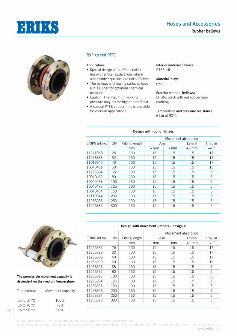
RX® 50 red PTFE
The permissible movement capacity isdependent on the medium temperature: Temperature: Movement capacity:
up to 50 °C 100% up to 70 °C 75% up to 90 °C 60%
Application:
heavy chemical applications where other rubber qualities are not sufficient
a PTFE liner for optimum chemical resistance
pressure may not be higher than 6 bar!
for vacuum applications.
Interior material bellows:PTFE foil
Material inlays:nylon
Exterior material bellows:EPDM, black with red rubber label marking
Temperature and pressure resistance:6 bar at 90°C
Design with round flanges
Movement absorptionERIKS art.no. DN Fitting length Axial Lateral Angular mm + mm - mm +/- mm +/- °11241048 25 130 15 15 15 1711256383 32 130 15 15 15 1711019940 40 130 15 15 15 1710040461 50 130 15 15 15 1511256384 65 130 15 15 15 510040462 80 130 15 15 15 510040463 100 130 15 15 15 510040473 125 130 15 15 15 510040464 150 130 15 15 15 511119944 200 130 15 15 15 511256385 250 130 15 15 15 511256386 300 130 15 15 15 5
Design with movement limiters - design C
Movement absorptionERIKS art.no. DN Fitting length Axial Lateral Angular mm + mm - mm +/- mm +/- °11256387 25 130 15 15 15 1711256388 32 130 15 15 15 1711256389 40 130 15 15 15 1711256390 50 130 15 15 15 1511256391 65 130 15 15 15 511256392 80 130 15 15 15 511256393 100 130 15 15 15 511256394 125 130 15 15 15 511256395 150 130 15 15 15 511256396 200 130 15 15 15 511256397 250 130 15 15 15 511256398 300 130 15 15 15 5
Compensators
39
All the information in this documentation has been compiled with the greatest of care.
Despite this we can bear no responsibility whatsoever for any errors present in the documentation. The recommendations are intended as guidelines.
www.eriks.info
Rubber bellows
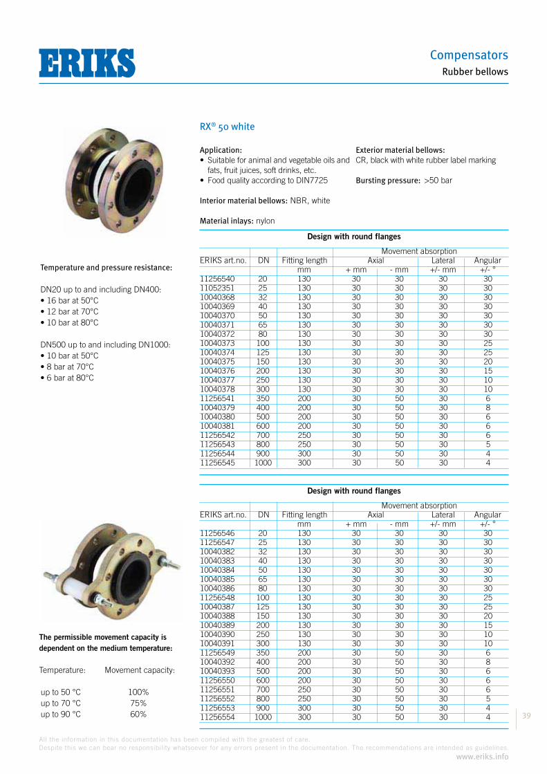
RX® 50 white
The permissible movement capacity isdependent on the medium temperature: Temperature: Movement capacity:
up to 50 °C 100% up to 70 °C 75% up to 90 °C 60%
Application:
fats, fruit juices, soft drinks, etc.
Interior material bellows: NBR, white
Material inlays: nylon
Exterior material bellows:CR, black with white rubber label marking
Bursting pressure:
Design with round flanges
Movement absorptionERIKS art.no. DN Fitting length Axial Lateral Angular mm + mm - mm +/- mm +/- °11256540 20 130 30 30 30 3011052351 25 130 30 30 30 3010040368 32 130 30 30 30 3010040369 40 130 30 30 30 3010040370 50 130 30 30 30 3010040371 65 130 30 30 30 3010040372 80 130 30 30 30 3010040373 100 130 30 30 30 2510040374 125 130 30 30 30 2510040375 150 130 30 30 30 2010040376 200 130 30 30 30 1510040377 250 130 30 30 30 1010040378 300 130 30 30 30 1011256541 350 200 30 50 30 610040379 400 200 30 50 30 810040380 500 200 30 50 30 610040381 600 200 30 50 30 611256542 700 250 30 50 30 611256543 800 250 30 50 30 511256544 900 300 30 50 30 411256545 1000 300 30 50 30 4
Design with round flanges
Movement absorptionERIKS art.no. DN Fitting length Axial Lateral Angular mm + mm - mm +/- mm +/- °11256546 20 130 30 30 30 3011256547 25 130 30 30 30 3010040382 32 130 30 30 30 3010040383 40 130 30 30 30 3010040384 50 130 30 30 30 3010040385 65 130 30 30 30 3010040386 80 130 30 30 30 3011256548 100 130 30 30 30 2510040387 125 130 30 30 30 2510040388 150 130 30 30 30 2010040389 200 130 30 30 30 1510040390 250 130 30 30 30 1010040391 300 130 30 30 30 1011256549 350 200 30 50 30 610040392 400 200 30 50 30 810040393 500 200 30 50 30 611256550 600 200 30 50 30 611256551 700 250 30 50 30 611256552 800 250 30 50 30 511256553 900 300 30 50 30 411256554 1000 300 30 50 30 4
Temperature and pressure resistance:
DN20 up to and including DN400:
DN500 up to and including DN1000:

Hoses and Accessories
40
All the information in this documentation has been compiled with the greatest of care.
Despite this we can bear no responsibility whatsoever for any errors present in the documentation. The recommendations are intended as guidelines.
www.eriks.info
Rubber bellows
RX® 50 white
The permissible movement capacity isdependent on the medium temperature: Temperature: Movement capacity:
up to 50 °C 100% up to 70 °C 75% up to 90 °C 60%
Application:
and fats, fruit juices, soft drinks, etc.
Interior material bellows: NBR, white
Material inlays: nylon
Exterior material bellows:CR, black with white rubber label marking
Flange material:Stainless steel 316 Ti (1.4571)
Bursting pressure:
Design with round flanges
Movement absorptionERIKS art.no. DN Fitting length Axial Lateral Angular mm + mm - mm +/- mm +/- °11259860 20 130 30 30 30 3011259861 25 130 30 30 30 3011259862 32 130 30 30 30 3011246423 40 130 30 30 30 3011042850 50 130 30 30 30 3011034523 65 130 30 30 30 3011033217 80 130 30 30 30 3011033218 100 130 30 30 30 2511259863 125 130 30 30 30 2511110712 150 130 30 30 30 2011110710 200 130 30 30 30 1511259864 250 130 30 30 30 1011259865 300 130 30 30 30 1011259866 350 200 30 50 30 611259867 400 200 30 50 30 811259868 500 200 30 50 30 6
Design with movement limiters - design C
Movement absorptionERIKS art.no. DN Fitting length Axial Lateral Angular mm + mm - mm +/- mm +/- °11259874 20 130 30 30 30 3011259875 25 130 30 30 30 3011259876 32 130 30 30 30 3011259877 40 130 30 30 30 3011259878 50 130 30 30 30 3011259879 65 130 30 30 30 3011259880 80 130 30 30 30 3011097704 100 130 30 30 30 2511259881 125 130 30 30 30 2511259882 150 130 30 30 30 2011259883 200 130 30 30 30 1511259884 250 130 30 30 30 1011259885 300 130 30 30 30 1011259886 350 200 30 50 30 611259887 400 200 30 50 30 811259888 500 200 30 50 30 6
Temperature and pressure resistance:
DN20 up to and including DN400:
DN500 up to and including DN1000:
DESIGN WITHSTAINLESS STEEL FLANGES

Compensators
41
All the information in this documentation has been compiled with the greatest of care.
Despite this we can bear no responsibility whatsoever for any errors present in the documentation. The recommendations are intended as guidelines.
www.eriks.info
Rubber bellows
RX® 50 black/CR
The permissible movement capacity isdependent on the medium temperature: Temperature: Movement capacity:
up to 50 °C 100% up to 70 °C 75% up to 90 °C 60%
Application:suitable for cold and hot water
Interior material bellows:CR, black
Material inlays:nylon
Exterior material bellows:EPDM, black with grey rubber label marking
Temperature and pressure resistance:
Design with round flanges
Movement absorptionERIKS art.no. DN Fitting length Axial Lateral Angular mm + mm - mm +/- mm +/- °11256379 20 130 30 30 30 3011256380 25 130 30 30 30 3010040394 32 130 30 30 30 3010040395 40 130 30 30 30 3010040396 50 130 30 30 30 3010040397 65 130 30 30 30 3010040398 80 130 30 30 30 3010040399 100 130 30 30 30 2510040400 125 130 30 30 30 2510040401 150 130 30 30 30 2010040402 200 130 30 30 30 1510040403 250 130 30 30 30 1010040404 300 130 30 30 30 10
Design with movement limiters - design C
Movement absorptionERIKS art.no. DN Fitting length Axial Lateral Angular mm + mm - mm +/- mm +/- °11256381 20 130 30 30 30 3011256382 25 130 30 30 30 3010040405 32 130 30 30 30 3010040406 40 130 30 30 30 3010040407 50 130 30 30 30 3010040408 65 130 30 30 30 3010040409 80 130 30 30 30 3010040410 100 130 30 30 30 2510040411 125 130 30 30 30 2510040412 150 130 30 30 30 2010040413 200 130 30 30 30 1510040414 250 130 30 30 30 1010040415 300 130 30 30 30 10
Hoses and Accessories
42
All the information in this documentation has been compiled with the greatest of care.
Despite this we can bear no responsibility whatsoever for any errors present in the documentation. The recommendations are intended as guidelines.
www.eriks.info
Rubber bellows
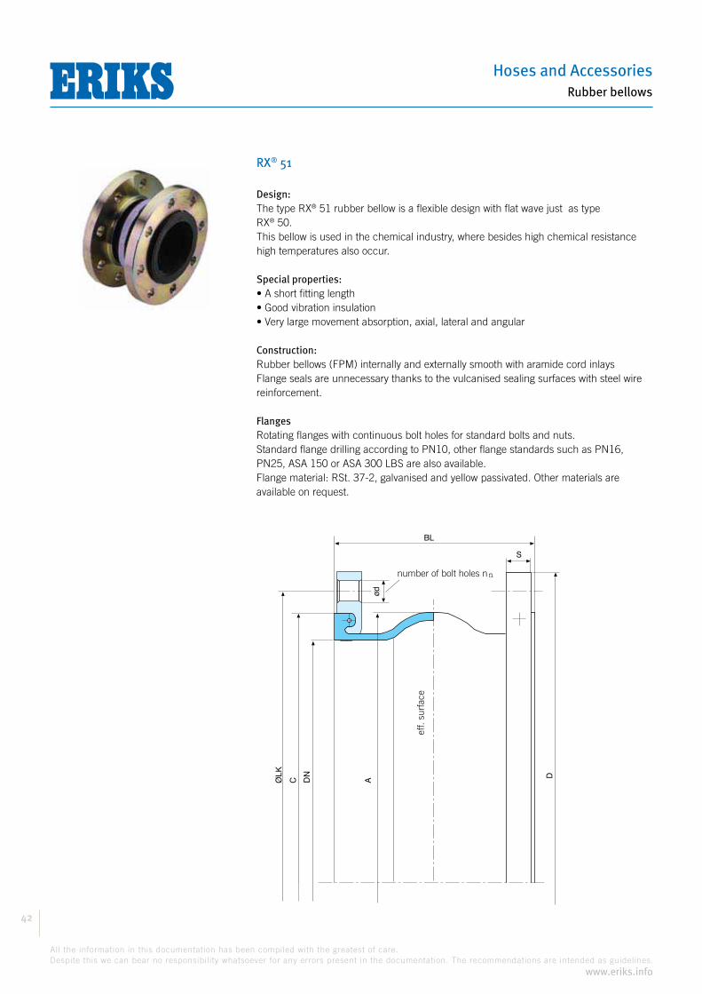
RX® 51
Design:® 51 rubber bellow is a flexible design with flat wave just as type
® 50.This bellow is used in the chemical industry, where besides high chemical resistance high temperatures also occur.
Special properties:
Construction:Rubber bellows (FPM) internally and externally smooth with aramide cord inlaysFlange seals are unnecessary thanks to the vulcanised sealing surfaces with steel wire reinforcement.
FlangesRotating flanges with continuous bolt holes for standard bolts and nuts.Standard flange drilling according to PN10, other flange standards such as PN16, PN25, ASA 150 or ASA 300 LBS are also available.Flange material: RSt. 37-2, galvanised and yellow passivated. Other materials are available on request.
Eff. opp.
aantal boutgaten n
S
BL
ød
A DDN
CØLK
eff.
surf
ace
number of bolt holes n
Compensators
43
All the information in this documentation has been compiled with the greatest of care.
Despite this we can bear no responsibility whatsoever for any errors present in the documentation. The recommendations are intended as guidelines.
www.eriks.info
Rubber bellows
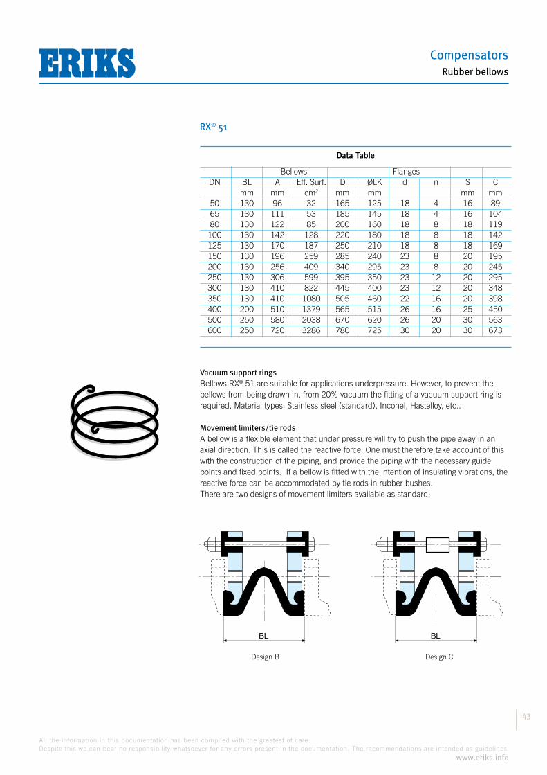
RX® 51
Design B Design C
Data Table
Bellows Flanges DN BL A Eff. Surf. D ØLK d n S C mm mm cm2 mm mm mm mm 50 130 96 32 165 125 18 4 16 89 65 130 111 53 185 145 18 4 16 104 80 130 122 85 200 160 18 8 18 119 100 130 142 128 220 180 18 8 18 142 125 130 170 187 250 210 18 8 18 169 150 130 196 259 285 240 23 8 20 195 200 130 256 409 340 295 23 8 20 245 250 130 306 599 395 350 23 12 20 295 300 130 410 822 445 400 23 12 20 348 350 130 410 1080 505 460 22 16 20 398 400 200 510 1379 565 515 26 16 25 450 500 250 580 2038 670 620 26 20 30 563 600 250 720 3286 780 725 30 20 30 673
Vacuum support rings® 51 are suitable for applications underpressure. However, to prevent the
bellows from being drawn in, from 20% vacuum the fitting of a vacuum support ring is required. Material types: Stainless steel (standard), Inconel, Hastelloy, etc..
Movement limiters/tie rodsA bellow is a flexible element that under pressure will try to push the pipe away in an axial direction. This is called the reactive force. One must therefore take account of this with the construction of the piping, and provide the piping with the necessary guide points and fixed points. If a bellow is fitted with the intention of insulating vibrations, the reactive force can be accommodated by tie rods in rubber bushes.There are two designs of movement limiters available as standard:
BL BL

Hoses and Accessories
44
All the information in this documentation has been compiled with the greatest of care.
Despite this we can bear no responsibility whatsoever for any errors present in the documentation. The recommendations are intended as guidelines.
www.eriks.info
Rubber bellows
RX® 51 lilac
The permissible movement capacity isdependent on the medium temperature: Temperature: Movement capacity:
up to 50 °C 100% up to 70 °C 75% up to 90 °C 60%
Application:Suitable for heavy chemicals,also for higher temperatures
Interior material bellows:FPM
Material inlays:aramide
Exterior material bellows:EPDM, black with lilac rubber label marking
Temperature and pressure resistance:
Bursting pressure:
Design with round flanges
Movement absorptionERIKS art.no. DN Fitting length Axial Lateral Angular mm + mm - mm +/- mm +/- °10040416 40 130 20 10 15 2010040417 50 130 20 10 15 2010040418 65 130 20 10 15 2010040419 80 130 20 15 15 2010040420 100 130 20 15 15 2010040421 125 130 20 15 15 2010040422 150 130 20 15 15 2010040423 200 130 20 15 15 1510040424 250 130 20 15 15 1010040425 300 130 20 15 15 1011256733 350 130 20 15 15 1010040426 400 200 25 20 20 810040427 500 250 25 20 20 610040428 600 250 25 20 20 6
Design with movement limiters - design C
Movement absorptionERIKS art.no. DN Fitting length Axial Lateral Angular mm + mm - mm +/- mm +/- °10040429 40 130 20 10 15 2010040430 50 130 20 10 15 2010040431 65 130 20 10 15 2010040432 80 130 20 15 15 2010040433 100 130 20 15 15 2010040434 125 130 20 15 15 2010040435 150 130 20 15 15 2010040436 200 130 20 15 15 1510040437 250 130 20 15 15 1010040438 300 130 20 15 15 1011256734 350 130 20 15 15 1010040439 400 200 25 20 20 810040440 500 250 25 20 20 611256735 600 250 25 20 20 6

Compensators
45
All the information in this documentation has been compiled with the greatest of care.
Despite this we can bear no responsibility whatsoever for any errors present in the documentation. The recommendations are intended as guidelines.
www.eriks.info
Rubber bellows
RX® 55
Design:® 55 is a flexible design with flat wave.
This bellow is used for all industrial applications such as machine and piping construction, central tank farms, the paper industry, food industry, petrochemical industry, etc.
Special properties:
sizing is not sufficient
The rubber bellows are available in 5 different rubber qualities.The rubber quality is indicated by colour coding.
Construction:Rubber bellows internally and externally smooth with strong nylon or aramide cord inlays. Flange seals are unnecessary thanks to the vulcanised sealing surfaces with steel wire reinforcement.
Flanges:Rotating flanges with continuous bolt holes for standard bolts and nuts.Standard flange drilling according to PN10, other flange standards such as PN16, PN25, ASA 150 or ASA 300 LBS are also available.Flange material: RSt. 37-2, galvanised and yellow passivated.Other materials are available on request.
Eff. opp.
aantal boutgaten n
S
BL
ød
A DDN
CØLK
eff.
surf
ace
number of bolt holes n
Bellows Flanges DN BL A Eff. Surf. D ØLK d n S C mm mm cm2 mm mm mm mm 32 125 81 17 140 100 18 4 16 65 40 125 86 18 150 110 18 4 16 74 50 125 96 32 165 125 18 4 16 86 65 125 110 53 185 145 18 4 16 105 80 150 122 85 200 160 18 8 18 118 100 150 142 128 220 180 18 8 18 137 125 150 170 187 250 210 18 8 18 166 150 150 196 259 285 240 23 8 20 192 200 175 256 409 340 295 23 8 20 245 250 175 306 599 395 350 23 12 20 295 300 200 410 822 445 400 23 12 20 354 350 200 470 1080 505 460 22 16 20 398 400 200 480 1379 565 515 26 16 25 470 450 250 530 1801 615 565 26 20 25 490 500 250 580 2038 670 620 26 20 30 563 600 250 720 3310 780 725 30 20 30 673 700 275 800 4019 895 840 30 24 35 778 800 250 880 5436 1015 950 33 24 40 878 900 300 981 6706 1115 1050 33 28 40 978 1000 300 1086 8231 1230 1160 36 28 40 1078

Hoses and Accessories
46
All the information in this documentation has been compiled with the greatest of care.
Despite this we can bear no responsibility whatsoever for any errors present in the documentation. The recommendations are intended as guidelines.
www.eriks.info
Rubber bellows
RX® 55
Vacuum support rings:® 55 are suitable for applicationsunderpressure. However, to prevent the
bellows from being drawn in, from 20% vacuum the fitting of a vacuum support ring is required. Material types: Stainless steel (standard), Inconel, Hastelloy, etc.
Movement limiters/tie rods:A bellow is a flexible element that under pressure will try to push the pipe away in an axial direction. This is called the reactive force. One must therefore take account of this with the construction of the piping, and provide the piping with the necessary guide points and fixed points. If a bellow is fitted with the intention of insulating vibrations, the reactive force can be accommodated by tie rods in rubber bushes.There are two designs of movement limiters available as standard:
Design B Design C
BL BL

Compensators
47
All the information in this documentation has been compiled with the greatest of care.
Despite this we can bear no responsibility whatsoever for any errors present in the documentation. The recommendations are intended as guidelines.
www.eriks.info
Rubber bellows
RX® 55 yellow
The permissible movement capacity isdependent on the medium temperature: Temperature: Movement capacity:
up to 50 °C 100% up to 70 °C 75% up to 90 °C 60%
Application:Suitable for petrol, diesel, heating oil, oil, lubricating oil and natural gas
Interior material bellows: NBR, black
Material inlays: nylon
Exterior material bellows:CR, black with yellow rubber label marking
Bursting pressure:
Design with round flanges
Movement absorptionERIKS art.no. DN Fitting length Axial Lateral Angular mm + mm - mm +/- mm +/- °11256704 32 125 30 30 30 3511163678 40 125 30 30 30 3511256705 50 125 30 30 30 3011163675 65 125 30 30 30 1011256706 80 150 30 30 30 1011207806 100 150 30 30 30 1011048446 125 150 30 30 30 1011163680 150 150 30 30 30 1011112335 200 175 15 40 20 1011115254 250 175 15 40 20 1011256707 300 200 30 40 30 1011256708 350 200 15 40 20 1011256709 400 200 30 50 30 811256710 450 250 20 40 30 611256711 500 250 20 40 30 611256712 600 250 20 40 30 611256713 700 275 30 50 50 611256714 800 250 30 50 30 511256715 900 300 20 30 30 411256716 1000 300 20 30 30 4
Design with round flanges
Movement absorptionERIKS art.no. DN Fitting length Axial Lateral Angular mm + mm - mm +/- mm +/- °11256717 32 125 30 30 30 3511101558 40 125 30 30 30 3511107307 50 125 30 30 30 3011101557 65 125 30 30 30 1011256718 80 150 30 30 30 1011030170 100 150 30 30 30 1011256719 125 150 30 30 30 1011256720 150 150 30 30 30 1011256721 200 175 15 40 20 1011256722 250 175 15 40 20 1011256723 300 200 30 40 30 1011256724 350 200 15 40 20 1011256725 400 200 30 50 30 811256726 450 250 20 40 30 611256727 500 250 20 40 30 611256728 600 250 20 40 30 611256729 700 275 30 50 50 611256730 800 250 30 50 30 511256731 900 300 20 30 30 411256732 1000 300 20 30 30 4
Temperature and pressure resistance:

Hoses and Accessories
48
All the information in this documentation has been compiled with the greatest of care.
Despite this we can bear no responsibility whatsoever for any errors present in the documentation. The recommendations are intended as guidelines.
www.eriks.info
Rubber bellows
RX® 55 green
The permissible movement capacity isdependent on the medium temperature: Temperature: Movement capacity:
up to 50 °C 100% up to 70 °C 75% up to 90 °C 60%
Application:
Consult the resistance list or ask ERIKS for advice
the medium
Interior material bellows: CSM, black
Material inlays: nylon
Exterior material bellows:CSM, black with green rubber label marking
Bursting pressure:
Design with round flanges
Movement absorptionERIKS art.no. DN Fitting length Axial Lateral Angular mm + mm - mm +/- mm +/- °11256665 32 125 30 30 30 3511256666 40 125 30 30 30 3511256667 50 125 30 30 30 3011256668 65 125 30 30 30 1011256669 80 150 30 30 30 1011256670 100 150 30 30 30 1011256671 125 150 30 30 30 1011256672 150 150 30 30 30 1011256673 200 175 15 40 20 1011256674 250 175 15 40 20 1011256675 300 200 30 40 30 1011256676 350 200 15 40 20 1011119496 400 200 30 50 30 811256677 450 250 20 40 30 611256678 500 250 20 40 30 611256679 600 250 20 40 30 611256680 700 275 30 50 50 611256681 800 250 30 50 30 511256682 900 300 20 30 30 411256683 1000 300 20 30 30 4
Design with round flanges
Movement absorptionERIKS art.no. DN Fitting length Axial Lateral Angular mm + mm - mm +/- mm +/- °11256684 32 125 30 30 30 3511256685 40 125 30 30 30 3511256686 50 125 30 30 30 3011256687 65 125 30 30 30 1011256688 80 150 30 30 30 1011256689 100 150 30 30 30 1011256690 125 150 30 30 30 1011256691 150 150 30 30 30 1011256692 200 175 15 40 20 1011256693 250 175 15 40 20 1011256694 300 200 30 40 30 1011256695 350 200 15 40 20 1011256696 400 200 30 50 30 811256697 450 250 20 40 30 611256698 500 250 20 40 30 611256699 600 250 20 40 30 611256700 700 275 30 50 50 611256701 800 250 30 50 30 511256702 900 300 20 30 30 411256703 1000 300 20 30 30 4
Temperature and pressure resistance:

Compensators
49
All the information in this documentation has been compiled with the greatest of care.
Despite this we can bear no responsibility whatsoever for any errors present in the documentation. The recommendations are intended as guidelines.
www.eriks.info
Rubber bellows
RX® 55 red aramide
The permissible movement capacity isdependent on the medium temperature: Temperature: Movement capacity:
up to 50 °C 100% up to 70 °C 75% up to 90 °C 60%
Application:
installations
Interior material bellows: EPDM, black
Material inlays: aramide
Exterior material bellows:EPDM, black with green rubber label marking
Bursting pressure:
Design with round flanges
Movement absorptionERIKS art.no. DN Fitting length Axial Lateral Angular mm + mm - mm +/- mm +/- °11092856 32 125 30 30 30 3511092859 40 125 30 30 30 3511256637 50 125 30 30 30 3011101246 65 125 30 30 30 1011101247 80 150 30 30 30 1011101248 100 150 30 30 30 1011101249 125 150 30 30 30 1011092858 150 150 30 30 30 1011050401 200 175 15 40 20 1011256638 250 175 15 40 20 1011066135 300 200 30 40 30 1011256639 350 200 15 40 20 1011256640 400 200 30 50 30 811256641 450 250 20 40 30 611055064 500 250 20 40 30 611055063 600 250 20 40 30 611256642 700 275 30 50 50 611256643 800 250 30 50 30 511256644 900 300 20 30 30 411256645 1000 300 20 30 30 4
Design with round flanges
Movement absorptionERIKS art.no. DN Fitting length Axial Lateral Angular mm + mm - mm +/- mm +/- °11256646 32 125 30 30 30 3511256647 40 125 30 30 30 3511256648 50 125 30 30 30 3011022997 65 125 30 30 30 1011256649 80 150 30 30 30 1011256650 100 150 30 30 30 1011256651 125 150 30 30 30 1011256652 150 150 30 30 30 1011256653 200 175 15 40 20 1011256654 250 175 15 40 20 1011256655 300 200 30 40 30 1011256656 350 200 15 40 20 1011256657 400 200 30 50 30 811256658 450 250 20 40 30 611256659 500 250 20 40 30 611256660 600 250 20 40 30 611256661 700 275 30 50 50 611256662 800 250 30 50 30 511256663 900 300 20 30 30 411256664 1000 300 20 30 30 4
Temperature and pressure resistance:
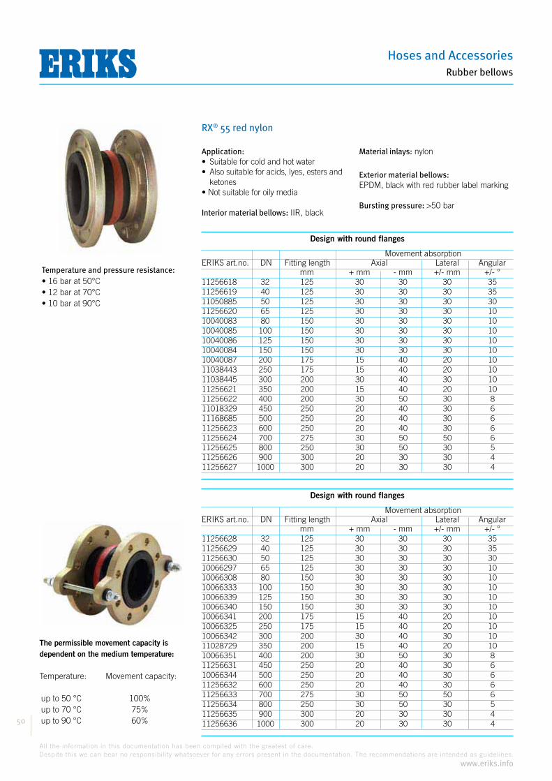
Hoses and Accessories
50
All the information in this documentation has been compiled with the greatest of care.
Despite this we can bear no responsibility whatsoever for any errors present in the documentation. The recommendations are intended as guidelines.
www.eriks.info
Rubber bellows
RX® 55 red nylon
The permissible movement capacity isdependent on the medium temperature: Temperature: Movement capacity:
up to 50 °C 100% up to 70 °C 75% up to 90 °C 60%
Application:
ketones
Interior material bellows: IIR, black
Material inlays: nylon
Exterior material bellows:EPDM, black with red rubber label marking
Bursting pressure:
Design with round flanges
Movement absorptionERIKS art.no. DN Fitting length Axial Lateral Angular mm + mm - mm +/- mm +/- °11256618 32 125 30 30 30 3511256619 40 125 30 30 30 3511050885 50 125 30 30 30 3011256620 65 125 30 30 30 1010040083 80 150 30 30 30 1010040085 100 150 30 30 30 1010040086 125 150 30 30 30 1010040084 150 150 30 30 30 1010040087 200 175 15 40 20 1011038443 250 175 15 40 20 1011038445 300 200 30 40 30 1011256621 350 200 15 40 20 1011256622 400 200 30 50 30 811018329 450 250 20 40 30 611168685 500 250 20 40 30 611256623 600 250 20 40 30 611256624 700 275 30 50 50 611256625 800 250 30 50 30 511256626 900 300 20 30 30 411256627 1000 300 20 30 30 4
Design with round flanges
Movement absorptionERIKS art.no. DN Fitting length Axial Lateral Angular mm + mm - mm +/- mm +/- °11256628 32 125 30 30 30 3511256629 40 125 30 30 30 3511256630 50 125 30 30 30 3010066297 65 125 30 30 30 1010066308 80 150 30 30 30 1010066333 100 150 30 30 30 1010066339 125 150 30 30 30 1010066340 150 150 30 30 30 1010066341 200 175 15 40 20 1010066325 250 175 15 40 20 1010066342 300 200 30 40 30 1011028729 350 200 15 40 20 1010066351 400 200 30 50 30 811256631 450 250 20 40 30 610066344 500 250 20 40 30 611256632 600 250 20 40 30 611256633 700 275 30 50 50 611256634 800 250 30 50 30 511256635 900 300 20 30 30 411256636 1000 300 20 30 30 4
Temperature and pressure resistance:

Compensators
51
All the information in this documentation has been compiled with the greatest of care.
Despite this we can bear no responsibility whatsoever for any errors present in the documentation. The recommendations are intended as guidelines.
www.eriks.info
Rubber bellows
RX® 55 white
The permissible movement capacity isdependent on the medium temperature: Temperature: Movement capacity:
up to 50 °C 100% up to 70 °C 75% up to 90 °C 60%
Application:
fats, fruit juices, soft drinks, etc.
Interior material bellows: NBR, white
Material inlays: nylon
Exterior material bellows:CR, black with white rubber label marking
Bursting pressure:
Design with round flanges
Movement absorptionERIKS art.no. DN Fitting length Axial Lateral Angular mm + mm - mm +/- mm +/- °11256581 32 125 30 30 30 3511256582 40 125 30 30 30 3511256583 50 125 30 30 30 3011256584 65 125 30 30 30 1011256585 80 150 30 30 30 1011256586 100 150 30 30 30 1011256587 125 150 30 30 30 1011256588 150 150 30 30 30 1011105910 200 175 15 40 20 1011105909 250 175 15 40 20 1011104922 300 200 30 40 30 1011256589 350 200 15 40 20 1011256590 400 200 30 50 30 811256591 450 250 20 40 30 611256592 500 250 20 40 30 611256593 600 250 20 40 30 611256594 700 275 30 50 50 611256595 800 250 30 50 30 511256596 900 300 20 30 30 411256597 1000 300 20 30 30 4
Design with round flanges
Movement absorptionERIKS art.no. DN Fitting length Axial Lateral Angular mm + mm - mm +/- mm +/- °11256598 32 125 30 30 30 3511256599 40 125 30 30 30 3511256600 50 125 30 30 30 3011256601 65 125 30 30 30 1011256602 80 150 30 30 30 1011256603 100 150 30 30 30 1011256604 125 150 30 30 30 1011256605 150 150 30 30 30 1011256606 200 175 15 40 20 1011256607 250 175 15 40 20 1011256608 300 200 30 40 30 1011256609 350 200 15 40 20 1011256610 400 200 30 50 30 811256611 450 250 20 40 30 611256612 500 250 20 40 30 611256613 600 250 20 40 30 611256614 700 275 30 50 50 611256615 800 250 30 50 30 511256616 900 300 20 30 30 411256617 1000 300 20 30 30 4
Temperature and pressure resistance:
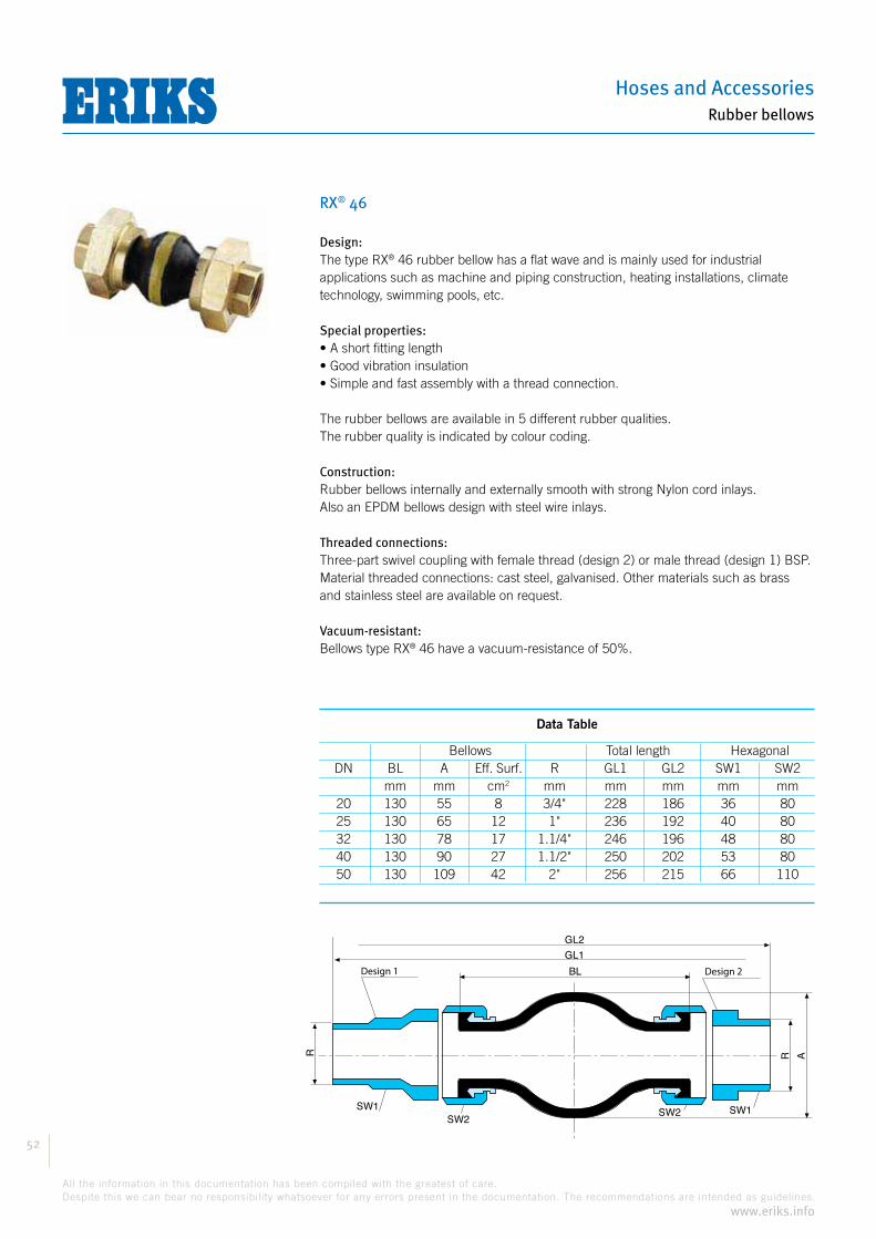
Hoses and Accessories
52
All the information in this documentation has been compiled with the greatest of care.
Despite this we can bear no responsibility whatsoever for any errors present in the documentation. The recommendations are intended as guidelines.
www.eriks.info
Rubber bellows
RX® 46
Design:® 46 rubber bellow has a flat wave and is mainly used for industrial
applications such as machine and piping construction, heating installations, climate technology, swimming pools, etc.
Special properties:
The rubber bellows are available in 5 different rubber qualities.The rubber quality is indicated by colour coding.
Construction:Rubber bellows internally and externally smooth with strong Nylon cord inlays.Also an EPDM bellows design with steel wire inlays.
Threaded connections:Three-part swivel coupling with female thread (design 2) or male thread (design 1) BSP.Material threaded connections: cast steel, galvanised. Other materials such as brass and stainless steel are available on request.
Vacuum-resistant:® 46 have a vacuum-resistance of 50%.
Data Table
Bellows Total length Hexagonal DN BL A Eff. Surf. R GL1 GL2 SW1 SW2 mm mm cm2 mm mm mm mm mm 20 130 55 8 3/4" 228 186 36 80 25 130 65 12 1" 236 192 40 80 32 130 78 17 1.1/4" 246 196 48 80 40 130 90 27 1.1/2" 250 202 53 80 50 130 109 42 2" 256 215 66 110
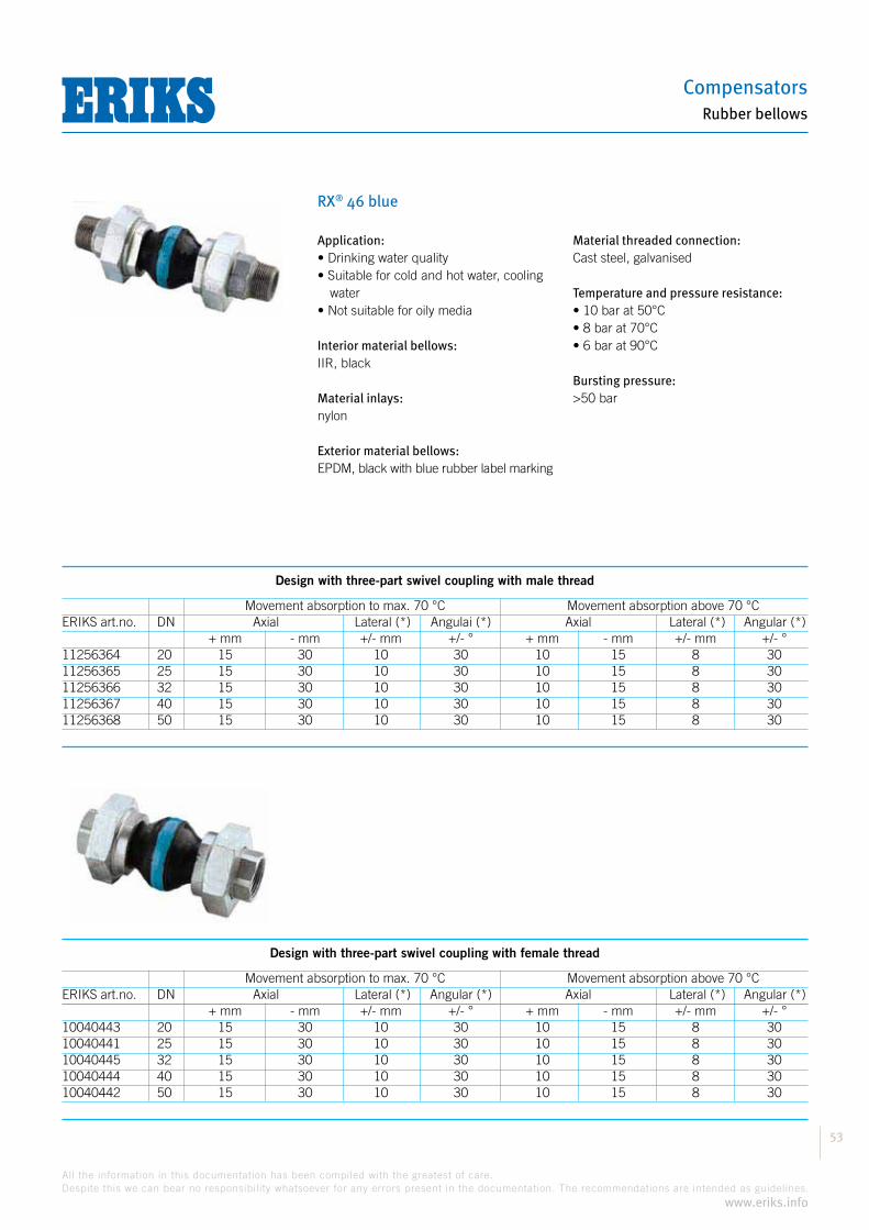
Compensators
53
All the information in this documentation has been compiled with the greatest of care.
Despite this we can bear no responsibility whatsoever for any errors present in the documentation. The recommendations are intended as guidelines.
www.eriks.info
Rubber bellows
RX® 46 blue
Design with three-part swivel coupling with male thread
Movement absorption to max. 70 °C Movement absorption above 70 °C
+ mm - mm +/- mm +/- ° + mm - mm +/- mm +/- °11256364 20 15 30 10 30 10 15 8 3011256365 25 15 30 10 30 10 15 8 3011256366 32 15 30 10 30 10 15 8 3011256367 40 15 30 10 30 10 15 8 3011256368 50 15 30 10 30 10 15 8 30
Design with three-part swivel coupling with female thread
Movement absorption to max. 70 °C Movement absorption above 70 °C
+ mm - mm +/- mm +/- ° + mm - mm +/- mm +/- °10040443 20 15 30 10 30 10 15 8 3010040441 25 15 30 10 30 10 15 8 3010040445 32 15 30 10 30 10 15 8 3010040444 40 15 30 10 30 10 15 8 3010040442 50 15 30 10 30 10 15 8 30
Application:
water
Interior material bellows:IIR, black
Material inlays:nylon
Exterior material bellows:EPDM, black with blue rubber label marking
Material threaded connection:Cast steel, galvanised
Temperature and pressure resistance:
Bursting pressure:
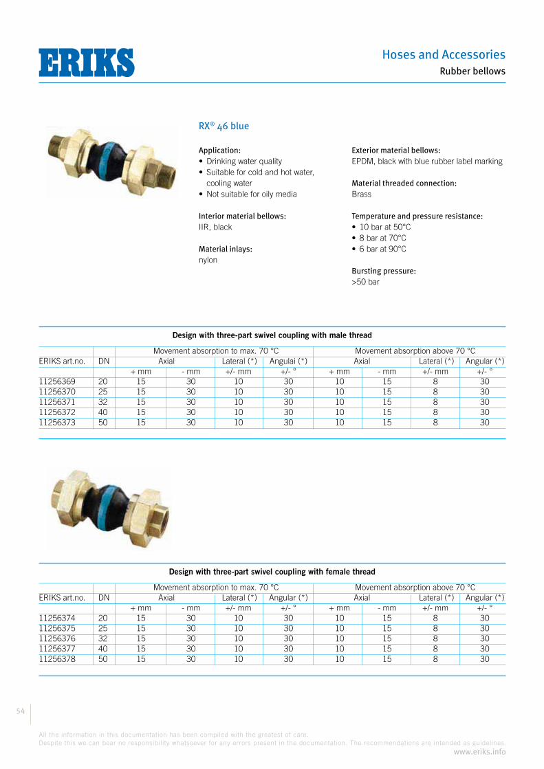
Hoses and Accessories
54
All the information in this documentation has been compiled with the greatest of care.
Despite this we can bear no responsibility whatsoever for any errors present in the documentation. The recommendations are intended as guidelines.
www.eriks.info
Rubber bellows
RX® 46 blue
Design with three-part swivel coupling with male thread
Movement absorption to max. 70 °C Movement absorption above 70 °C
+ mm - mm +/- mm +/- ° + mm - mm +/- mm +/- °11256369 20 15 30 10 30 10 15 8 3011256370 25 15 30 10 30 10 15 8 3011256371 32 15 30 10 30 10 15 8 3011256372 40 15 30 10 30 10 15 8 3011256373 50 15 30 10 30 10 15 8 30
Design with three-part swivel coupling with female thread
Movement absorption to max. 70 °C Movement absorption above 70 °C
+ mm - mm +/- mm +/- ° + mm - mm +/- mm +/- °11256374 20 15 30 10 30 10 15 8 3011256375 25 15 30 10 30 10 15 8 3011256376 32 15 30 10 30 10 15 8 3011256377 40 15 30 10 30 10 15 8 3011256378 50 15 30 10 30 10 15 8 30
Application:
cooling water
Interior material bellows:IIR, black
Material inlays:nylon
Exterior material bellows:EPDM, black with blue rubber label marking
Material threaded connection:Brass
Temperature and pressure resistance:
Bursting pressure:

Compensators
55
All the information in this documentation has been compiled with the greatest of care.
Despite this we can bear no responsibility whatsoever for any errors present in the documentation. The recommendations are intended as guidelines.
www.eriks.info
Rubber bellows
RX® 46 yellow
Design with three-part swivel coupling with male thread
Movement absorption to max. 70 °C Movement absorption above 70 °C
+ mm - mm +/- mm +/- ° + mm - mm +/- mm +/- °11256339 20 15 30 10 30 10 15 8 3011256362 25 15 30 10 30 10 15 8 3011256363 32 15 30 10 30 10 15 8 3010040521 40 15 30 10 30 10 15 8 3010040522 50 15 30 10 30 10 15 8 30
Design with three-part swivel coupling with female thread
Movement absorption to max. 70 °C Movement absorption above 70 °C
+ mm - mm +/- mm +/- ° + mm - mm +/- mm +/- °10040448 20 15 30 10 30 10 15 8 3010040446 25 15 30 10 30 10 15 8 3010040450 32 15 30 10 30 10 15 8 3010040449 40 15 30 10 30 10 15 8 3010040447 50 15 30 10 30 10 15 8 30
Application:Suitable for mineral oil products, engine fuels and gases
Interior material bellows:NBR, black
Material inlays:nylon
Exterior material bellows:CR, black with yellow rubber label marking
Material threaded connection:Cast steel, galvanised
Temperature and pressure resistance:
Bursting pressure:

Hoses and Accessories
56
All the information in this documentation has been compiled with the greatest of care.
Despite this we can bear no responsibility whatsoever for any errors present in the documentation. The recommendations are intended as guidelines.
www.eriks.info
Rubber bellows
RX® 46 grey
Design with three-part swivel coupling with male thread
Movement absorption to max. 70 °C Movement absorption above 70 °C
+ mm - mm +/- mm +/- ° + mm - mm +/- mm +/- °11256352 20 15 30 10 30 15 10 8 3011256353 25 15 30 10 30 15 10 8 3011256354 32 15 30 10 30 15 10 8 3011256355 40 15 30 10 30 15 10 8 3011256356 50 15 30 10 30 15 10 8 30
Design with three-part swivel coupling with female thread
Movement absorption to max. 70 °C Movement absorption above 70 °C
+ mm - mm +/- mm +/- ° + mm - mm +/- mm +/- °11256357 20 15 30 10 30 15 10 8 3011256358 25 15 30 10 30 15 10 8 3011256359 32 15 30 10 30 15 10 8 3011256360 40 15 30 10 30 15 10 8 3011256361 50 15 30 10 30 15 10 8 30
Application:Suitable for cold and hot water, seawater, pool water and waste water(also oil-bearing)
Interior material bellows:CR, black
Material inlays:nylon
Exterior material bellows:CR, black with grey rubber label marking
Material threaded connection:Cast steel, galvanised
Temperature and pressure resistance:16 bar at 70°C
Bursting pressure:

Compensators
57
All the information in this documentation has been compiled with the greatest of care.
Despite this we can bear no responsibility whatsoever for any errors present in the documentation. The recommendations are intended as guidelines.
www.eriks.info
Rubber bellows
RX® 46 red nylon
Design with three-part swivel coupling with male thread
Movement absorption to max. 70 °C Movement absorption above 70 °C
+ mm - mm +/- mm +/- ° + mm - mm +/- mm +/- °11256267 20 15 30 10 30 10 15 8 3011256268 25 15 30 10 30 10 15 8 3011256269 32 15 30 10 30 10 15 8 3011256270 40 15 30 10 30 10 15 8 3011256271 50 15 30 10 30 10 15 8 30
Design with three-part swivel coupling with female thread
Movement absorption to max. 70 °C Movement absorption above 70 °C
+ mm - mm +/- mm +/- ° + mm - mm +/- mm +/- °11256272 20 15 30 10 30 10 15 8 3011256343 25 15 30 10 30 10 15 8 3011256344 32 15 30 10 30 10 15 8 3011256345 40 15 30 10 30 10 15 8 3011256346 50 15 30 10 30 10 15 8 30
Application:
and ketones
Interior material bellows:EPDM, black
Material inlays:nylon
Exterior material bellows:EPDM, black with red rubber label marking
Material threaded connection:Cast steel, galvanised
Temperature and pressure resistance:
Bursting pressure:

Hoses and Accessories
58
All the information in this documentation has been compiled with the greatest of care.
Despite this we can bear no responsibility whatsoever for any errors present in the documentation. The recommendations are intended as guidelines.
www.eriks.info
Rubber bellows
RX® 46 red steel
Design with three-part swivel coupling with male thread
Movement absorption to max. 70 °C Movement absorption above 70 °C
+ mm - mm +/- mm +/- ° + mm - mm +/- mm +/- °11256347 20 15 30 10 30 10 15 8 3011256348 25 15 30 10 30 10 15 8 3011256349 32 15 30 10 30 10 15 8 3011256350 40 15 30 10 30 10 15 8 3011256351 50 15 30 10 30 10 15 8 30
Design with three-part swivel coupling with female thread
Movement absorption to max. 70 °C Movement absorption above 70 °C
+ mm - mm +/- mm +/- ° + mm - mm +/- mm +/- °10040453 20 15 30 10 30 10 15 8 3010040451 25 15 30 10 30 10 15 8 3010040455 32 15 30 10 30 10 15 8 3010040454 40 15 30 10 30 10 15 8 3010040452 50 15 30 10 30 10 15 8 30
Application:
installations
Interior material bellows:EPDM, black
Material inlays:steel cord
Exterior material bellows:EPDM, black with red rubber label marking
Material threaded connection:Cast steel, galvanised
Temperature and pressure resistance:
Bursting pressure:

Compensators
59
All the information in this documentation has been compiled with the greatest of care.
Despite this we can bear no responsibility whatsoever for any errors present in the documentation. The recommendations are intended as guidelines.
www.eriks.info
Rubber bellows
RX® 48
Design:® 48 is a very flexible design with high wave.
This bellow is mainly used in the steel industry.
Special properties:
Construction:Rubber bellows internally and externally smooth with strong Nylon cord inlays.Flange seals are unnecessary thanks to the vulcanised sealing surfaces with steel wire reinforcement.
Flanges:Rotating flanges with continuous bolt holes for standard bolts and nuts. Standard flange drilling according to PN10, other flange standards such as PN16, PN25, ASA150 or ASA 300 LBS are also available.Flange material: RSt. 37-2, galvanised and yellow passivated.Other materials are available on request.
Bellows Flanges DN BL A Eff. Surf. D ØLK d n S C mm mm cm2 mm mm mm mm 50 150 135 32 165 125 18 4 15 96 65 150 150 53 185 145 18 4 15 116 80 150 170 85 200 160 18 8 15 133 100 155 200 128 220 180 18 8 15 153 125 155 225 187 250 210 18 8 20 178 150 155 250 259 285 240 23 8 20 203 200 160 295 410 340 295 23 8 20 261 250 170 345 596 395 350 23 12 20 311
S
BL
ØD
ØLk
/ n
x Ø
d ØA
ØC
DN

Hoses and Accessories
60
All the information in this documentation has been compiled with the greatest of care.
Despite this we can bear no responsibility whatsoever for any errors present in the documentation. The recommendations are intended as guidelines.
www.eriks.info
Rubber bellows
RX® 48
Vacuum support rings:® 48 are suitable for applications underpressure. However, to prevent the
bellows from being drawn in, from 20% vacuum the fitting of a vacuum support ring is required. Material types: Stainless steel (standard), Inconel, Hastelloy, etc.
Movement limiters/tie rods:A bellow is a flexible element that under pressure will try to push the pipe away in an axial direction. This is called the reactive force. One must therefore take account of this with the construction of the piping, and provide the piping with the necessary guide points and fixed points. If a bellow is fitted with the intention of insulating vibrations, the reactive force can be accommodated by tie rods in rubber bushes.There are two designs of movement limiters available as standard:
Design B Design C
BL BL

Compensators
61
All the information in this documentation has been compiled with the greatest of care.
Despite this we can bear no responsibility whatsoever for any errors present in the documentation. The recommendations are intended as guidelines.
www.eriks.info
Rubber bellows
RX® 48 red
The permissible movement capacity isdependent on the medium temperature: Temperature: Movement capacity:
up to 50 °C 100% up to 70 °C 75% up to 90 °C 60%
Application:
ketones
Interior material bellows:EPDM, black
Material inlays:nylon
Exterior material bellows:EPDM, black with red rubber label marking
Temperature and pressure resistance:
Bursting pressure:
Design with round flanges
Movement absorptionERIKS art.no. DN Fitting length Axial Lateral Angular mm + mm - mm +/- mm +/- °11260239 50 150 25 25 20 3011260240 65 150 25 25 20 3011260241 80 150 25 25 20 3011260242 100 155 30 40 25 3011260313 125 155 30 45 25 2511260314 150 155 35 45 25 2011089186 200 160 35 45 25 2011260315 250 170 35 45 25 20

Hoses and Accessories
62
All the information in this documentation has been compiled with the greatest of care.
Despite this we can bear no responsibility whatsoever for any errors present in the documentation. The recommendations are intended as guidelines.
www.eriks.info
Rubber bellows
RX® 61
Design:® 61 is a flat-waved bellow with cylindrical connections.
Assembly of the bellow is quick and simple using hose clips.This bellow is used for applications such as: engine cooling systems, discharge pipes, aeration installations, etc.
Special properties:
fitted on a pipe
The rubber bellows are available as standard in 2 different rubber qualities, EPDM and NBR. The rubber quality is indicated by colour coding.Other rubber qualities are available on request.
Construction:Rubber bellows internally and externally smooth with strong Nylon cord inlays.
Cylindrical ends:To guarantee an optimum connection the external pipe diameter must match the inside diameter of the cylindrical connections of the bellow. The external surface of the pipe must be smooth and clean. Grind welded joints as necessary. We advise using wide clamps(at least 20 mm width) for assembly. One clamp is sufficient up to a working pressure of 2 bar, above 2 bar 2 clamps per connection must be used.
Vacuum support rings® 61 are vacuum-tight. However, to prevent the bellows from being drawn in,
from 20% vacuum the fitting of a vacuum support ring is required.Material types: Stainless steel (standard), Inconel, Hastelloy, etc.
Bellow DN Di BL A S H B mm mm cm2 mm 50 60,3 250 120 5 97 55 65 76,1 250 135 6 97 55 80 88,9 250 158 6 85 80 100 114,3 250 183 6 85 80 125 139,7 250 208 6 85 80 150 168,3 250 254 7 65 120 175 193,7 250 278 7 65 120 200 219,1 250 304 7 65 120 225 227 250 311 7 65 120 250 273 250 359 7 65 120 300 323,9 250 408 7 65 120 350 355,6 250 439 7 65 120 400 406,4 250 491 8 60 130 500 508 250 594 8 60 130 600 610 250 696 8 60 130
S
BL
A
BH
DI

Compensators
63
All the information in this documentation has been compiled with the greatest of care.
Despite this we can bear no responsibility whatsoever for any errors present in the documentation. The recommendations are intended as guidelines.
www.eriks.info
Rubber bellows
RX® 61 yellow
The permissible movement capacity isdependent on the medium temperature: Temperature: Movement capacity:
up to 50 °C 100% up to 70 °C 75% up to 90 °C 60%
Application:Suitable for mineral oil, lubricating oil, fats, oil-bearing cooling water
Interior material bellows:NBR, black
Material inlays:nylon
Exterior material bellows:NBR, black with yellow rubber label marking
Temperature and pressure resistance:
Bursting pressure:
Design for band clamp assembly
Movement absorptionERIKS art.no. DN Int. Ø Fitting length Axial Lateral Angular mm mm + mm - mm +/- mm +/- °11100667 50 60,3 250 20 25 15 2011256568 65 76,1 250 20 25 15 2011054894 80 88,9 250 20 25 15 2011256569 100 114,3 250 20 25 15 2011256570 125 139,7 250 20 25 15 2011256571 150 168,3 250 20 25 15 1511256572 175 193,7 250 20 25 15 1511256573 200 219,1 250 20 25 15 1011256574 225 227 250 20 25 15 1011256575 250 273 250 20 25 15 1011256576 300 323,9 250 20 25 15 811256577 350 355,6 250 20 25 15 811256578 400 406,4 250 20 25 15 811256579 500 508 250 20 25 15 611256580 600 610 250 20 25 15 6

Hoses and Accessories
64
All the information in this documentation has been compiled with the greatest of care.
Despite this we can bear no responsibility whatsoever for any errors present in the documentation. The recommendations are intended as guidelines.
www.eriks.info
Rubber bellows
RX® 61 red nylon
The permissible movement capacity isdependent on the medium temperature: Temperature: Movement capacity:
up to 50 °C 100% up to 70 °C 75% up to 90 °C 60%
Application:
and ketones
Interior material bellows:EPDM, black
Material inlays:nylon
Exterior material bellows:EPDM, black with red rubber label marking
Temperature and pressure resistance:
Bursting pressure:
Note:Clamping strips available in galvanised steel or stainless steel
Design for band clamp assembly
Movement absorptionERIKS art.no. DN Int. Ø Fitting length Axial Lateral Angular mm mm + mm - mm +/- mm +/- °11256555 50 60,3 250 20 25 15 2011061288 65 76,1 250 20 25 15 2011256556 80 88,9 250 20 25 15 2011256557 100 114,3 250 20 25 15 2011256558 125 139,7 250 20 25 15 2011256559 150 168,3 250 20 25 15 1511256560 175 193,7 250 20 25 15 1511256561 200 219,1 250 20 25 15 1011256562 225 227 250 20 25 15 1011105555 250 273 250 20 25 15 1011256563 300 323,9 250 20 25 15 811256564 350 355,6 250 20 25 15 811256565 400 406,4 250 20 25 15 811256566 500 508 250 20 25 15 611256567 600 610 250 20 25 15 6
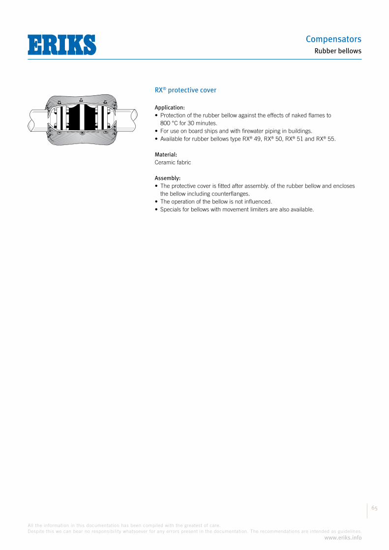
Compensators
65
All the information in this documentation has been compiled with the greatest of care.
Despite this we can bear no responsibility whatsoever for any errors present in the documentation. The recommendations are intended as guidelines.
www.eriks.info
Rubber bellows
RX® protective cover
Application:
800 °C for 30 minutes.
® ® ® ® 55.
Material:Ceramic fabric
Assembly:
the bellow including counterflanges.

Hoses and Accessories
66
All the information in this documentation has been compiled with the greatest of care.
Despite this we can bear no responsibility whatsoever for any errors present in the documentation. The recommendations are intended as guidelines.
www.eriks.info
Rubber bellows
RX® liner
RX® earth-retaining covers
Application:
Material:Stainless steel 1.4301 (AISI 304)
Design:
be accommodated
Application:The earth-retaining cover consists of two parts specially designed for rubber bellows fitted in buried piping.The construction is such that there is no influence on the movement capabilities of the bellow.
Design:Two-part cover of St. 37.2 or stainless steel. For bellows without limitersthe cover is assembled on the counterflange.For bellows with limiters the cover is welded on the piping system. With plastic or cast-iron piping systems the cover is fixed to the piping using clamps.Available for all types with or without limiters.
Uitvoering 1
Uitvoering 2
B A
View A View B
for bellows without limiters for bellows with limiters
Design 1
Design 2
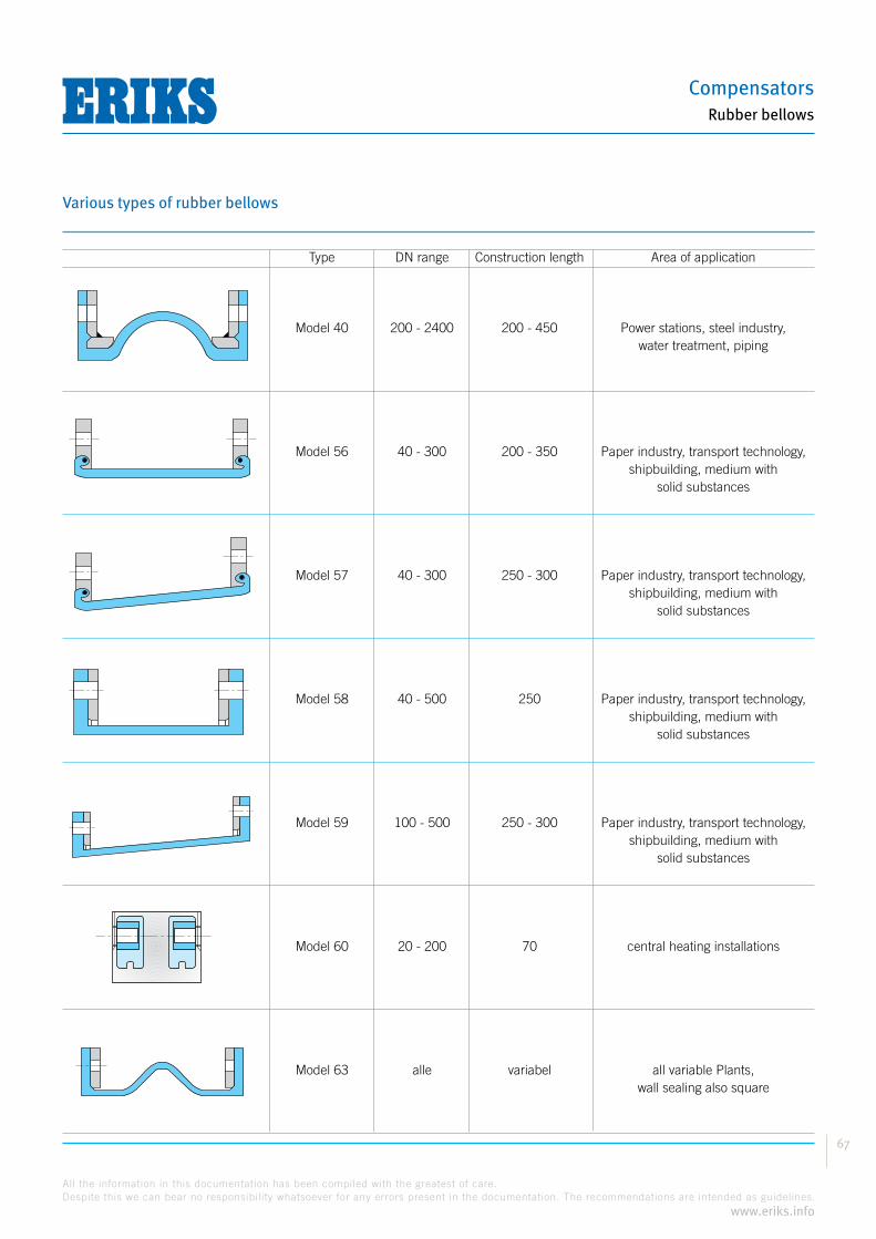
Compensators
67
All the information in this documentation has been compiled with the greatest of care.
Despite this we can bear no responsibility whatsoever for any errors present in the documentation. The recommendations are intended as guidelines.
www.eriks.info
Rubber bellows
Various types of rubber bellows
Type DN range Construction length Area of application Model 40 200 - 2400 200 - 450 Power stations, steel industry, water treatment, piping
Model 56 40 - 300 200 - 350 Paper industry, transport technology, shipbuilding, medium with solid substances
Model 57 40 - 300 250 - 300 Paper industry, transport technology, shipbuilding, medium with solid substances
Model 58 40 - 500 250 Paper industry, transport technology, shipbuilding, medium with solid substances
Model 59 100 - 500 250 - 300 Paper industry, transport technology, shipbuilding, medium with solid substances
Model 60 20 - 200 70 central heating installations
Model 63 alle variabel all variable Plants, wall sealing also square

Hoses and Accessories
68
All the information in this documentation has been compiled with the greatest of care.
Despite this we can bear no responsibility whatsoever for any errors present in the documentation. The recommendations are intended as guidelines.
www.eriks.info
Rubber bellows
Question list for rubber bellows
When choosing rubber bellows it is important to know the operating conditions. A question list is included below to facilitate analysing the most important information.If you submit a completed copy of this list with your enquiry or order this will help in arriving at the right choice.
Company: ................................................................................ Contact person: ...............................................................................
Address: ................................................................................ ................................................................................ ............................
Telephone: ..................................................... Enquiry/projects: ................................................. Date: ...............................................
Required number of bellows: .......................................................................................................................................................
Operating conditionsMedium: Movement:
Composition and nature: ......................................................... Axial compression: ........................................................
Temperature of medium: ......................................................... Axial elongation: ........................................................
Pressure of the medium: ........................................................ Lateral plus: ........................................................
Pressure changes: ........................................................ Lateral min: ........................................................
Temperature of environment: ........................................................ Angular movement: ........................................................
Flow speed: ........................................................ Frequency: ........................................................
Size:
Nominal passage: ............................................................................
Nominal length: ............................................................................
connections: ............................................................................
Is the pipe insulated? ............................................................................ yes/no
Remarks:...................................................................................................................................................................................................................................................................................................................................................................................................................................................................................................................................................................................................................................................................................................................................................................................................................................................................................................................................................................................................................................................................................................................................................................................................................................................................................................................................................................................................................................................................................................................................................................................................................................................................................................................................................................................................................................................................................................

Compensators
69
All the information in this documentation has been compiled with the greatest of care.
Despite this we can bear no responsibility whatsoever for any errors present in the documentation. The recommendations are intended as guidelines.
www.eriks.info
Stainless steel bellows
Metal bellows or stainless steel bellows
IntroductionThe correct application of metal bellows often involves custom work. Besidesthe standard range we therefore supply bellows designed for your application such as exhaust gas bellows to a DN6000, high pressure bellows with 20 layers and 250 bar working pressure, etc.
Standard materials such as stainless steel or carbon steel are not always sufficient. For highly aggressive substances it may be necessary to make use of nickel alloys such as monel, incoloy, inconel or Halstelloy-C.
The standard range includes different kinds of metal bellows depending on their movement absorption. There are axial, lateral and hinging bellows, with or without tie rods, hinge or universal constructions.Our technical specialists are always ready to advise you.
Pressure/temperature correction factor according to DIN 17440, table 6All metal bellows are classified in different pressure classes.For example: PN2.5, PN10, PN16, PN25This design pressure is based on a temperature of 120 °C and bellows material stainless steel AISI 321 (1.4541).For other temperatures the allowed maximum working pressure can be calculated using the table below. The correction factor must be multiplied by the design pressure of the bellow.
Temp. (°C) Correction factor 20 1,183 50 1,095 100 1,026 120 1,000 150 0,962 200 0,912 250 0,863 300 0,823 350 0,794 400 0,769 450 0,750 500 0,735 550 0,725

Hoses and Accessories
70
All the information in this documentation has been compiled with the greatest of care.
Despite this we can bear no responsibility whatsoever for any errors present in the documentation. The recommendations are intended as guidelines.
www.eriks.info
Stainless steel bellows
Metal bellows or stainless steel bellows
Material/pressure correction factorThe choice of material influences the maximum working pressure.In the table below you can find the correction factor that must be multiplied by the maximum working pressure.
LinerA liner is recommended when the following problems can originate:
convolutions of the bellows and impede the free movement of the bellow
medium
ensuring of a smooth flow
to the EJMA recommendations a liner must be provided with the adjacent medium speeds:
Gases:
Material Correction factor AISI 304 (1.4301) 0,958 AISI 304L (1.4306) 0,896 AISI 321 (1.4541) 1 AISI 316 (1.4401) 1 AISI 316L (1.4404) 0,938 AISI 316Ti (1.4571) 1,042
8,07,57,06,56,05,55,04,54,03,53,02,52,01,51,00,50,0
m/s
DN25DN50
DN80
DN100
DN125
DN150
DN200
DN250
DN300
DN350
DN400
DN450
DN500
Liquids:
3,5
3
2,5
2
1,5
1
0,5
0
m/s
DN25DN50
DN80
DN100
DN125
DN150
DN200
DN250
DN300
DN350
DN400
DN450
DN500

Compensators
71
All the information in this documentation has been compiled with the greatest of care.
Despite this we can bear no responsibility whatsoever for any errors present in the documentation. The recommendations are intended as guidelines.
www.eriks.info
Stainless steel bellows
RX® KS SS/ST PN16
Application:High temperatures possibly combined with high pressures, such as steam, thermal oil, hot water, chemicals, etc.
Design:Single stainless steel bellow with socket or butt welds
Material bellows:Stainless steel AISI 316Ti (1.4571)
Pressure class:PN16
Material socket or butt welds:Carbon steel St. 35.8
Note:Also available with bellows in stainless steel AISI 321 (1.4541) and stainless steel socket or butt welds. Other materials on request
Type RX® KS SS/ST PN16
ERIKS Fitting length Movement Spring constant Socket Bellows art. no. (BL) absorption Axial or butt welds DN (+/-3%) Axial (+/-30%) D S Di Do Eff.Surf. Weight mm ±mm N/mm mm mm mm mm cm2 kg10040030 15 148 9 29 21,3 2 16 26 3 0,1310040031 20 151 11 28 26,9 2,3 20 31 5 0,1810040032 25 152 13 24 33,7 2,6 25 39 8 0,2510040033 32 186 13 36 42,4 2,6 32 48 12 0,4010040034 40 202 18 76 48,3 2,6 41 59 19 0,6710040035 50 224 23 70 60,3 2,9 50 70 28 0,9710040036 65 235 23 66 76,1 2,9 65 88 46 1,2710040037 80 205 20 73 88,9 3,2 79 104 66 1,2110040038 100 205 20 77 114,3 3,6 99 127 100 1,6210040039 125 210 25 121 139,7 4 124 155 153 2,3710040040 150 256 25 118 168,3 4,5 150 184 218 3,7610040041 200 276 25 133 219,1 5,6 200 235 371 5,9111296203 250 313 20 398 273,0 6,3 250 285 560 10,8010040043 300 338 25 376 323,9 7,1 300 337 795 14,35
Please take account of the pressure and temperature correction factors. See page 71.Other fitting lengths and movement absorption available on request.
BL
S
Do
D
Di
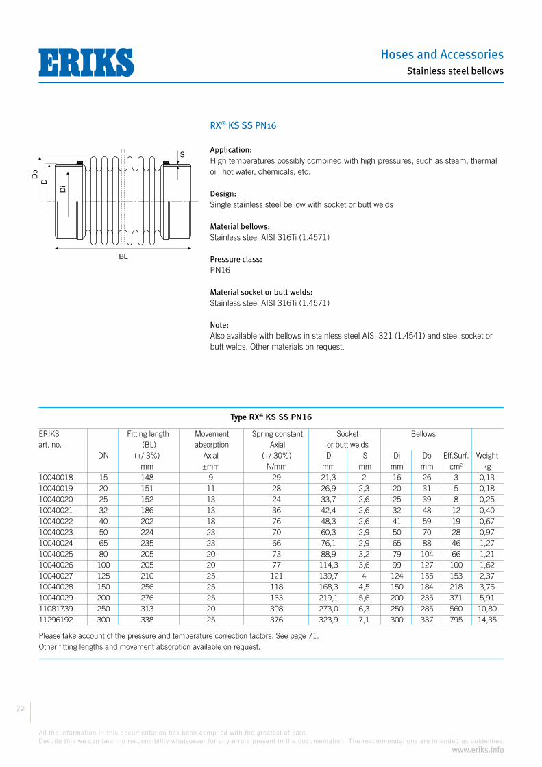
Hoses and Accessories
72
All the information in this documentation has been compiled with the greatest of care.
Despite this we can bear no responsibility whatsoever for any errors present in the documentation. The recommendations are intended as guidelines.
www.eriks.info
Stainless steel bellows
RX® KS SS PN16
Application:High temperatures possibly combined with high pressures, such as steam, thermal oil, hot water, chemicals, etc.
Design:Single stainless steel bellow with socket or butt welds
Material bellows:Stainless steel AISI 316Ti (1.4571)
Pressure class:PN16
Material socket or butt welds:Stainless steel AISI 316Ti (1.4571)
Note:Also available with bellows in stainless steel AISI 321 (1.4541) and steel socket or butt welds. Other materials on request.
Type RX® KS SS PN16
ERIKS Fitting length Movement Spring constant Socket Bellows art. no. (BL) absorption Axial or butt welds DN (+/-3%) Axial (+/-30%) D S Di Do Eff.Surf. Weight mm ±mm N/mm mm mm mm mm cm2 kg10040018 15 148 9 29 21,3 2 16 26 3 0,1310040019 20 151 11 28 26,9 2,3 20 31 5 0,1810040020 25 152 13 24 33,7 2,6 25 39 8 0,2510040021 32 186 13 36 42,4 2,6 32 48 12 0,4010040022 40 202 18 76 48,3 2,6 41 59 19 0,6710040023 50 224 23 70 60,3 2,9 50 70 28 0,9710040024 65 235 23 66 76,1 2,9 65 88 46 1,2710040025 80 205 20 73 88,9 3,2 79 104 66 1,2110040026 100 205 20 77 114,3 3,6 99 127 100 1,6210040027 125 210 25 121 139,7 4 124 155 153 2,3710040028 150 256 25 118 168,3 4,5 150 184 218 3,7610040029 200 276 25 133 219,1 5,6 200 235 371 5,9111081739 250 313 20 398 273,0 6,3 250 285 560 10,8011296192 300 338 25 376 323,9 7,1 300 337 795 14,35
Please take account of the pressure and temperature correction factors. See page 71.Other fitting lengths and movement absorption available on request.
BL
S
Do
D
Di

Compensators
73
All the information in this documentation has been compiled with the greatest of care.
Despite this we can bear no responsibility whatsoever for any errors present in the documentation. The recommendations are intended as guidelines.
www.eriks.info
Stainless steel bellows
RX® KSi SS/ST PN16 - with liner
Application:High temperatures possibly combined with high pressures, such as steam, thermal oil, hot water, chemicals, etc.
Design:Single stainless steel bellow with liner and socket or butt welds
Material bellows:Stainless steel AISI 316Ti (1.4571)
Pressure class:PN16
Material liner:Stainless steel AISI 316Ti (1.4571)
Material socket or butt welds:Carbon steel St. 35.8
Note:Also available with bellows and liner in stainless steel AISI 321 (1.4541) and stainless steel socket or butt welds. Other materials on request.
Type RX® KSi SS/ST PN16
ERIKS Fitting length Movement Spring constant Socket Bellows art. no. (BL) absorption Axial or butt welds DN (+/-3%) Axial (+/-30%) D S Di Do Eff.Surf. Weight mm ±mm N/mm mm mm mm mm cm2 kg11296204 15 148 9 29 21,3 2 16 26 3 0,1311296205 20 151 11 28 26,9 2,3 20 31 5 0,1811296206 25 152 13 24 33,7 2,6 25 39 8 0,2511296207 32 186 13 36 42,4 2,6 32 48 12 0,4011296208 40 202 18 76 48,3 2,6 41 59 19 0,6711090337 50 224 23 70 60,3 2,9 50 70 28 0,9711069806 65 235 23 66 76,1 2,9 65 88 46 1,2711296209 80 205 20 73 88,9 3,2 79 104 66 1,2111296210 100 205 20 77 114,3 3,6 99 127 100 1,6211296211 125 210 25 121 139,7 4 124 155 153 2,3711296212 150 256 25 118 168,3 4,5 150 184 218 3,7611296213 200 276 25 133 219,1 5,6 200 235 371 5,9111296214 250 313 20 398 273,0 6,3 250 285 560 10,8011296215 300 338 25 376 323,9 7,1 300 337 795 14,35
Please take account of the pressure and temperature correction factors. See page 71.Other fitting lengths and movement absorption available on request.
BL
S
Do
D
Di

Hoses and Accessories
74
All the information in this documentation has been compiled with the greatest of care.
Despite this we can bear no responsibility whatsoever for any errors present in the documentation. The recommendations are intended as guidelines.
www.eriks.info
Stainless steel bellows
RX® KSi SS PN16 - with liner
Application:High temperatures possibly combined with high pressures, such as steam, thermal oil, hot water, chemicals, etc.
Design:Single stainless steel bellow with liner and socket or butt welds
Material bellows:Stainless steel AISI 316Ti (1.4571)
Pressure class:PN16
Material liner:Stainless steel AISI 316Ti (1.4571)
Material socket or butt welds:Stainless steel AISI 316Ti (1.4571)
Note:Also available with bellows and liner in stainless steel AISI 321 (1.4541) and steel socket or butt welds. Other materials on request.
Type RX® KSi SS PN16
ERIKS Fitting length Movement Spring constant Socket Bellows art. no. (BL) absorption Axial or butt welds DN (+/-3%) Axial (+/-30%) D S Di Do Eff.Surf. Weight mm ±mm N/mm mm mm mm mm cm2 kg11296216 15 148 9 29 21,3 2 16 26 3 0,1311296217 20 151 11 28 26,9 2,3 20 31 5 0,1811296218 25 152 13 24 33,7 2,6 25 39 8 0,2511296219 32 186 13 36 42,4 2,6 32 48 12 0,4011296220 40 202 18 76 48,3 2,6 41 59 19 0,6711296221 50 224 23 70 60,3 2,9 50 70 28 0,9711296222 65 235 23 66 76,1 2,9 65 88 46 1,2711296223 80 205 20 73 88,9 3,2 79 104 66 1,2111296224 100 205 20 77 114,3 3,6 99 127 100 1,6211296225 125 210 25 121 139,7 4 124 155 153 2,3711296226 150 256 25 118 168,3 4,5 150 184 218 3,7611296227 200 276 25 133 219,1 5,6 200 235 371 5,9111296228 250 313 20 398 273,0 6,3 250 285 560 10,8011296229 300 338 25 376 323,9 7,1 300 337 795 14,35
Please take account of the pressure and temperature correction factors. See page 71.Other fitting lengths and movement absorption available on request.
BL
S
Do
D
Di

Compensators
75
All the information in this documentation has been compiled with the greatest of care.
Despite this we can bear no responsibility whatsoever for any errors present in the documentation. The recommendations are intended as guidelines.
www.eriks.info
Stainless steel bellows
RX® KBF SS/ST PN16
Application:High temperatures possibly combined with high pressures, such as steam, thermal oil, hot water, chemicals, etc.
Design:Single stainless steel bellow with separate flanges
Material bellows:Stainless steel AISI 316Ti (1.4571)
Pressure class:PN16
Material welded collar:Stainless steel AISI 316Ti (1.4571)
Flange material:RSt. 37.2
Note:Also available with bellows in stainless steel AISI 321 (1.4541) and stainless steel flanges. Other flange standards on request.
Type RX® KBF SS/ST PN16
ERIKS Fitting Movement Spring Flanges Bellows art. no. length absorption constant (BL) Axial Axial DN (+/-3%) (+/-30%) D b k N d2 Db Di Do Eff.Surf. Weight mm ±mm N/mm mm mm mm mm mm mm mm mm cm2 kg10039994 15 63 9 29 95 14 65 4 14 45 16 26 3 1,3010039995 20 72 11 28 105 16 75 4 14 58 20 31 5 1,5910039996 25 79 13 24 115 16 85 4 14 68 25 39 8 2,0810039997 32 112 13 36 140 16 100 4 18 78 32 48 12 3,6110039998 40 132 18 76 150 16 110 4 18 88 41 59 19 3,8410039999 50 146 23 70 165 18 125 4 18 102 50 70 28 5,0310040000 65 157 23 66 185 18 145 4 18 122 65 88 46 5,9210040001 80 127 20 73 200 20 160 8 18 138 79 104 66 6,7010040002 100 137 20 77 220 20 180 8 18 158 99 127 100 7,6010040003 125 146 25 121 250 22 210 8 18 188 124 155 153 9,4010040004 150 152 25 118 285 22 240 8 22 212 150 184 218 11,6010040005 200 172 25 133 340 26 295 12 22 268 200 235 371 16,4011038369 250 169 20 398 405 32 355 12 26 320 250 285 560 26,5011296230 300 204 25 376 460 32 410 12 26 370 300 337 795 34,50
Please take account of the pressure and temperature correction factors. See page 71.Other fitting lengths and movement absorption available on request.
BL
N x d2b
k
Di
Do
Db
D
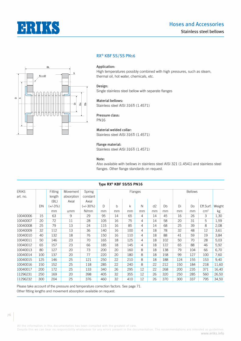
Hoses and Accessories
76
All the information in this documentation has been compiled with the greatest of care.
Despite this we can bear no responsibility whatsoever for any errors present in the documentation. The recommendations are intended as guidelines.
www.eriks.info
Stainless steel bellows
RX® KBF SS/SS PN16
Application:High temperatures possibly combined with high pressures, such as steam, thermal oil, hot water, chemicals, etc.
Design:Single stainless steel bellow with separate flanges
Material bellows:Stainless steel AISI 316Ti (1.4571)
Pressure class:PN16
Material welded collar:Stainless steel AISI 316Ti (1.4571)
Flange material:Stainless steel AISI 316Ti (1.4571)
Note:Also available with bellows in stainless steel AISI 321 (1.4541) and stainless steel flanges. Other flange standards on request.
Type RX® KBF SS/SS PN16
ERIKS Fitting Movement Spring Flanges Bellows art. no. length absorption constant (BL) Axial Axial DN (+/-3%) (+/-30%) D b k N d2 Db Di Do Eff.Surf. Weight mm ±mm N/mm mm mm mm mm mm mm mm mm cm2 kg10040006 15 63 9 29 95 14 65 4 14 45 16 26 3 1,3010040007 20 72 11 28 105 16 75 4 14 58 20 31 5 1,5910040008 25 79 13 24 115 16 85 4 14 68 25 39 8 2,0810040009 32 112 13 36 140 16 100 4 18 78 32 48 12 3,6110040010 40 132 18 76 150 16 110 4 18 88 41 59 19 3,8410040011 50 146 23 70 165 18 125 4 18 102 50 70 28 5,0310040012 65 157 23 66 185 18 145 4 18 122 65 88 46 5,9210040013 80 127 20 73 200 20 160 8 18 138 79 104 66 6,7010040014 100 137 20 77 220 20 180 8 18 158 99 127 100 7,6010040015 125 146 25 121 250 22 210 8 18 188 124 155 153 9,4010040016 150 152 25 118 285 22 240 8 22 212 150 184 218 11,6010040017 200 172 25 133 340 26 295 12 22 268 200 235 371 16,4011296231 250 169 20 398 405 32 355 12 26 320 250 285 560 26,5011296232 300 204 25 376 460 32 410 12 26 370 300 337 795 34,50
Please take account of the pressure and temperature correction factors. See page 71.Other fitting lengths and movement absorption available on request.
BL
N x d2b
k
Di
Do
Db
D

Compensators
77
All the information in this documentation has been compiled with the greatest of care.
Despite this we can bear no responsibility whatsoever for any errors present in the documentation. The recommendations are intended as guidelines.
www.eriks.info
Stainless steel bellows
RX® KBFi SS/ST PN16 - with liner
Application:High temperatures possibly combined with high pressures, such as steam, thermal oil, hot water, chemicals, etc.
Design:Single stainless steel bellow with separate flanges
Material bellows:Stainless steel AISI 316Ti (1.4571)
Pressure class:PN16
Material liner:Stainless steel AISI 316Ti (1.4571)
Flange material:RSt. 37.2
Note:Also available with bellows in stainless steel AISI 321 (1.4541) and stainless steel flanges. Other flange standards on request.
Type RX® KBFi SS/ST PN16
ERIKS Fitting Movement Spring Flanges Bellows art. no. length absorption constant (BL) Axial Axial DN (+/-3%) (+/-30%) D b k N d2 Db Di Do Eff.Surf. Weight mm ±mm N/mm mm mm mm mm mm mm mm mm cm2 kg11296233 15 63 9 29 95 14 65 4 14 45 12 26 3 1,3011296234 20 72 11 28 105 16 75 4 14 58 14 31 5 1,5911034047 25 79 13 24 115 16 85 4 14 68 20 39 8 2,0811031566 32 112 13 36 140 16 100 4 18 78 27 48 12 3,6111031568 40 132 18 76 150 16 110 4 18 88 35 59 19 3,8411031569 50 146 23 70 165 18 125 4 18 102 45 70 28 5,0311031978 65 157 23 66 185 18 145 4 18 122 60 88 46 5,9211031979 80 127 20 73 200 20 160 8 18 138 75 104 66 6,7011032030 100 137 20 77 220 20 180 8 18 158 95 127 100 7,6011032031 125 146 25 121 250 22 210 8 18 188 120 155 153 9,4011032032 150 152 25 118 285 22 240 8 22 212 146 184 218 11,6011038615 200 172 25 133 340 26 295 12 22 268 196 235 371 16,4011296235 250 169 20 398 405 32 355 12 26 320 246 285 560 26,5011296236 300 204 25 376 460 32 410 12 26 370 296 337 795 34,50
Please take account of the pressure and temperature correction factors. See page 71.Other fitting lengths and movement absorption available on request.
BL
N x d2b
k
Di
Do
Db
D

Hoses and Accessories
78
All the information in this documentation has been compiled with the greatest of care.
Despite this we can bear no responsibility whatsoever for any errors present in the documentation. The recommendations are intended as guidelines.
www.eriks.info
Stainless steel bellows
RX® KBFi SS PN16 - with liner
Application:High temperatures possibly combined with high pressures, such as steam, thermal oil, hot water, chemicals, etc.
Design:Single stainless steel bellow with separate flanges
Material bellows:Stainless steel AISI 316Ti (1.4571)
Pressure class:PN16
Material liner:Stainless steel AISI 316Ti (1.4571)
Flange material:Stainless steel AISI 316Ti (1.4571)
Note:Also available with bellows in stainless steel AISI 321 (1.4541) and stainless steel flanges. Other flange standards on request.
Type RX® KBFi SS PN16
ERIKS Fitting Movement Spring Flanges Bellows art. no. length absorption constant (BL) Axial Axial DN (+/-3%) (+/-30%) D b k N d2 Db Di Do Eff.Surf. Weight mm ±mm N/mm mm mm mm mm mm mm mm mm cm2 kg11296237 15 63 9 29 95 14 65 4 14 45 12 26 3 1,3011296238 20 72 11 28 105 16 75 4 14 58 14 31 5 1,5911142687 25 79 13 24 115 16 85 4 14 68 20 39 8 2,0811296239 32 112 13 36 140 16 100 4 18 78 27 48 12 3,6111296240 40 132 18 76 150 16 110 4 18 88 35 59 19 3,8411296241 50 146 23 70 165 18 125 4 18 102 45 70 28 5,0311296242 65 157 23 66 185 18 145 4 18 122 60 88 46 5,9211296243 80 127 20 73 200 20 160 8 18 138 75 104 66 6,7011296244 100 137 20 77 220 20 180 8 18 158 95 127 100 7,6011296245 125 146 25 121 250 22 210 8 18 188 120 155 153 9,4011296246 150 152 25 118 285 22 240 8 22 212 146 184 218 11,6011296247 200 172 25 133 340 26 295 12 22 268 196 235 371 16,4011296248 250 169 20 398 405 32 355 12 26 320 246 285 560 26,5011296249 300 204 25 376 460 32 410 12 26 370 296 337 795 34,50
Please take account of the pressure and temperature correction factors. See page 71.Other fitting lengths and movement absorption available on request.
BL
N x d2b
k
Di
Do
Db
D
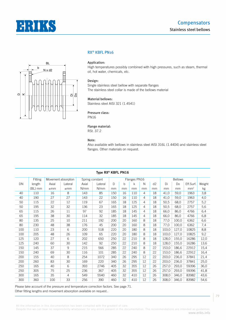
Compensators
79
All the information in this documentation has been compiled with the greatest of care.
Despite this we can bear no responsibility whatsoever for any errors present in the documentation. The recommendations are intended as guidelines.
www.eriks.info
Stainless steel bellows
RX® KBFL PN16
Application:High temperatures possibly combined with high pressures, such as steam, thermal oil, hot water, chemicals, etc.
Design:Single stainless steel bellow with separate flangesThe stainless steel collar is made of the bellows material
Material bellows:Stainless steel AISI 321 (1.4541)
Pressure class:PN16
Flange material:RSt. 37.2
Note:Also available with bellows in stainless steel AISI 316L (1.4404) and stainless steel flanges. Other materials on request.
Type RX® KBFL PN16
Fitting Movement absorption Spring constant Flanges PN16 Bellows DN length Axial Lateral Axial Lateral D b k N d2 Di Do Eff.Surf. Weight (BL) mm ±mm ±mm N/mm N/mm mm mm mm mm mm mm mm mm2 kg 40 110 16 8 143 85 150 16 110 4 18 41,0 59,0 1963 3,8 40 190 27 27 143 22 150 16 110 4 18 41,0 59,0 1963 4,0 50 115 22 12 119 67 165 18 125 4 18 50,5 68,0 2757 5,2 50 195 32 32 136 23 165 18 125 4 18 50,5 68,0 2757 5,6 65 115 26 11 97 92 185 18 145 4 18 66,0 86,0 4766 6,4 65 195 38 30 114 32 185 18 145 4 18 66,0 86,0 4766 6,8 80 135 25 10 211 192 200 20 160 8 18 77,0 100,0 6362 6,6 80 230 48 38 176 45 200 20 160 8 18 77,0 100,0 6362 7,4 100 110 23 6 200 518 220 20 180 8 18 103,0 127,0 10825 8,8 100 205 48 26 109 65 220 20 180 8 18 103,0 127,0 10825 9,2 125 120 27 6 202 650 250 22 210 8 18 128,0 155,0 16286 12,0 125 240 60 30 142 92 250 22 210 8 18 128,0 155,0 16286 13,6 150 145 37 9 215 566 285 22 240 8 22 153,0 186,6 22912 15,4 150 240 69 30 116 101 285 22 240 8 22 153,0 186,6 22912 16,4 200 155 40 8 254 1072 340 26 295 12 22 203,0 236,0 37841 21,4 200 260 83 30 169 220 340 26 295 12 22 203,0 236,0 37841 25,0 250 165 40 6 393 2746 405 32 355 12 26 257,0 293,0 59396 36,0 250 305 75 25 236 367 405 32 355 12 26 257,0 293,0 59396 41,8 300 165 35 4 549 5540 460 32 410 12 26 308,0 346,0 83982 43,6 300 360 100 33 256 390 460 32 410 12 26 308,0 346,0 83982 54,6
Please take account of the pressure and temperature correction factors. See page 71.Other fitting lengths and movement absorption available on request..
BL
D
N x d2b
K Di
Do
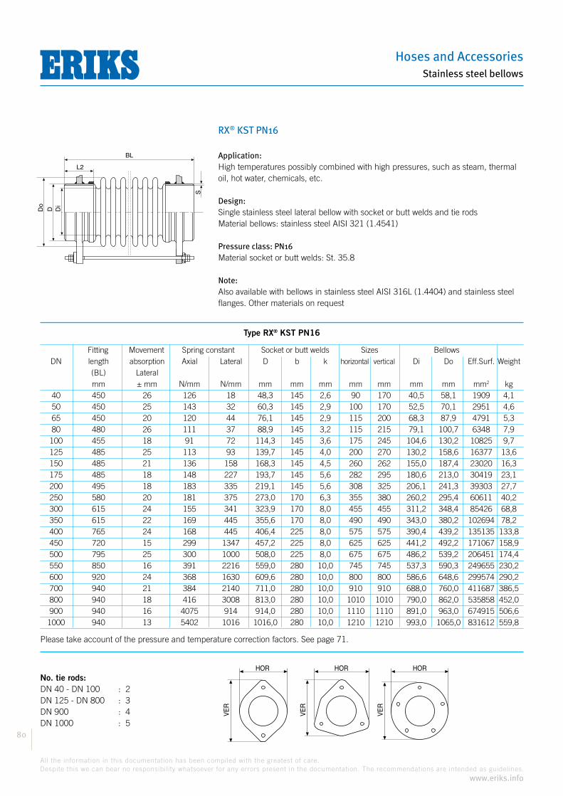
Hoses and Accessories
80
All the information in this documentation has been compiled with the greatest of care.
Despite this we can bear no responsibility whatsoever for any errors present in the documentation. The recommendations are intended as guidelines.
www.eriks.info
Stainless steel bellows
RX® KST PN16
Application:High temperatures possibly combined with high pressures, such as steam, thermal oil, hot water, chemicals, etc.
Design:Single stainless steel lateral bellow with socket or butt welds and tie rodsMaterial bellows: stainless steel AISI 321 (1.4541)
Pressure class: PN16Material socket or butt welds: St. 35.8
Note:Also available with bellows in stainless steel AISI 316L (1.4404) and stainless steel flanges. Other materials on request
Type RX® KST PN16
Fitting Movement Spring constant Socket or butt welds Sizes Bellows DN length absorption Axial Lateral D b k horizontal vertical Di Do Eff.Surf. Weight (BL) Lateral mm ± mm N/mm N/mm mm mm mm mm mm mm mm mm2 kg 40 450 26 126 18 48,3 145 2,6 90 170 40,5 58,1 1909 4,1 50 450 25 143 32 60,3 145 2,9 100 170 52,5 70,1 2951 4,6 65 450 20 120 44 76,1 145 2,9 115 200 68,3 87,9 4791 5,3 80 480 26 111 37 88,9 145 3,2 115 215 79,1 100,7 6348 7,9 100 455 18 91 72 114,3 145 3,6 175 245 104,6 130,2 10825 9,7 125 485 25 113 93 139,7 145 4,0 200 270 130,2 158,6 16377 13,6 150 485 21 136 158 168,3 145 4,5 260 262 155,0 187,4 23020 16,3 175 485 18 148 227 193,7 145 5,6 282 295 180,6 213,0 30419 23,1 200 495 18 183 335 219,1 145 5,6 308 325 206,1 241,3 39303 27,7 250 580 20 181 375 273,0 170 6,3 355 380 260,2 295,4 60611 40,2 300 615 24 155 341 323,9 170 8,0 455 455 311,2 348,4 85426 68,8 350 615 22 169 445 355,6 170 8,0 490 490 343,0 380,2 102694 78,2 400 765 24 168 445 406,4 225 8,0 575 575 390,4 439,2 135135 133,8 450 720 15 299 1347 457,2 225 8,0 625 625 441,2 492,2 171067 158,9 500 795 25 300 1000 508,0 225 8,0 675 675 486,2 539,2 206451 174,4 550 850 16 391 2216 559,0 280 10,0 745 745 537,3 590,3 249655 230,2 600 920 24 368 1630 609,6 280 10,0 800 800 586,6 648,6 299574 290,2 700 940 21 384 2140 711,0 280 10,0 910 910 688,0 760,0 411687 386,5 800 940 18 416 3008 813,0 280 10,0 1010 1010 790,0 862,0 535858 452,0 900 940 16 4075 914 914,0 280 10,0 1110 1110 891,0 963,0 674915 506,6 1000 940 13 5402 1016 1016,0 280 10,0 1210 1210 993,0 1065,0 831612 559,8
Please take account of the pressure and temperature correction factors. See page 71.
HOR
VE
R
HOR
VE
R
HOR
VE
R
No. tie rods:DN 40 - DN 100 : 2 DN 125 - DN 800 : 3DN 900 : 4DN 1000 : 5
BL
S
Do
D Di
L2
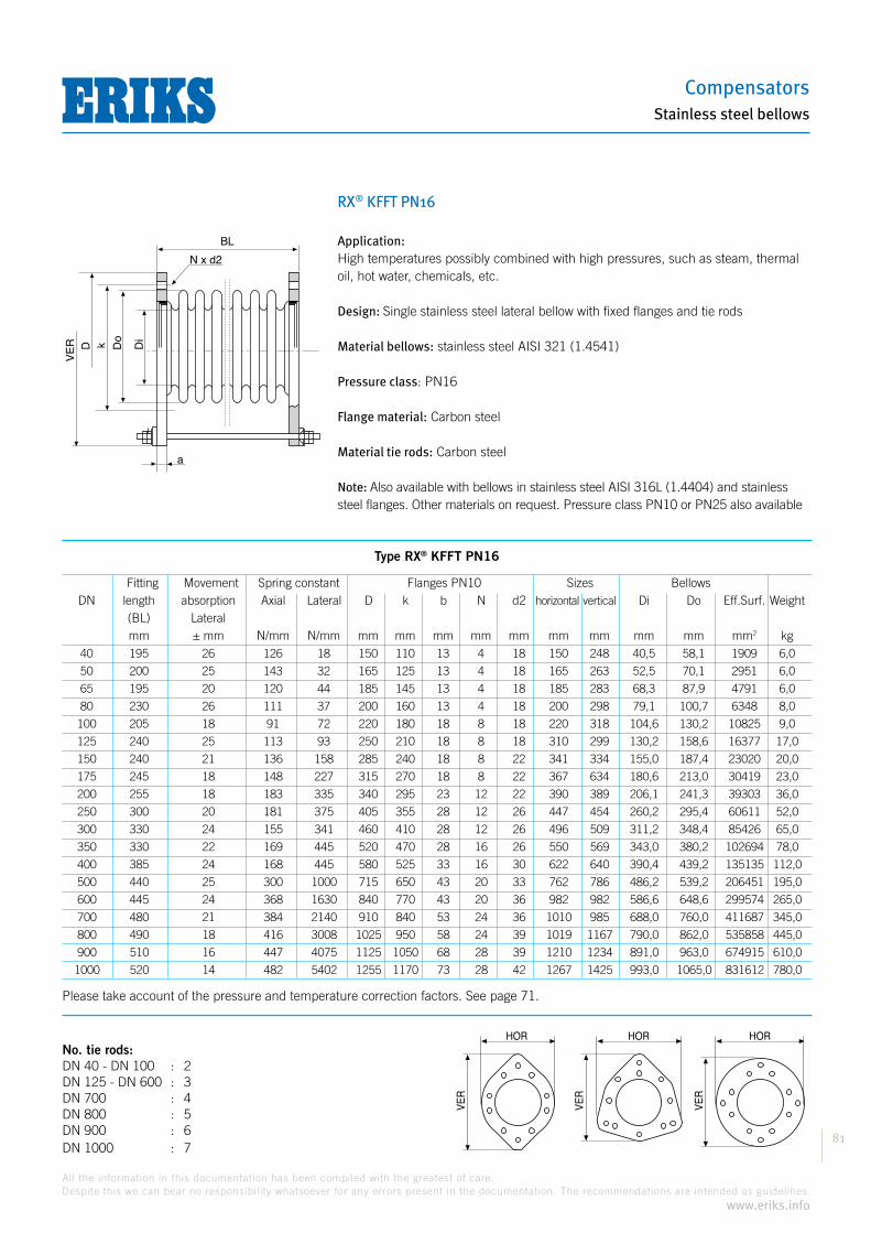
Compensators
81
All the information in this documentation has been compiled with the greatest of care.
Despite this we can bear no responsibility whatsoever for any errors present in the documentation. The recommendations are intended as guidelines.
www.eriks.info
Stainless steel bellows
RX® KFFT PN16
Application:High temperatures possibly combined with high pressures, such as steam, thermal oil, hot water, chemicals, etc.
Design: Single stainless steel lateral bellow with fixed flanges and tie rods
Material bellows: stainless steel AISI 321 (1.4541)
Pressure class: PN16
Flange material: Carbon steel
Material tie rods: Carbon steel
Note: Also available with bellows in stainless steel AISI 316L (1.4404) and stainless steel flanges. Other materials on request. Pressure class PN10 or PN25 also available
HOR
VE
R
HOR
VE
R
HOR
VE
R
No. tie rods:DN 40 - DN 100 : 2 DN 125 - DN 600 : 3DN 700 : 4DN 800 : 5DN 900 : 6 DN 1000 : 7
BL
Dok Di
DV
ER
N x d2
a
Type RX® KFFT PN16
Fitting Movement Spring constant Flanges PN10 Sizes Bellows DN length absorption Axial Lateral D k b N d2 horizontal vertical Di Do Eff.Surf. Weight (BL) Lateral mm ± mm N/mm N/mm mm mm mm mm mm mm mm mm mm mm2 kg 40 195 26 126 18 150 110 13 4 18 150 248 40,5 58,1 1909 6,0
50 200 25 143 32 165 125 13 4 18 165 263 52,5 70,1 2951 6,0
65 195 20 120 44 185 145 13 4 18 185 283 68,3 87,9 4791 6,0
80 230 26 111 37 200 160 13 4 18 200 298 79,1 100,7 6348 8,0
100 205 18 91 72 220 180 18 8 18 220 318 104,6 130,2 10825 9,0
125 240 25 113 93 250 210 18 8 18 310 299 130,2 158,6 16377 17,0
150 240 21 136 158 285 240 18 8 22 341 334 155,0 187,4 23020 20,0
175 245 18 148 227 315 270 18 8 22 367 634 180,6 213,0 30419 23,0
200 255 18 183 335 340 295 23 12 22 390 389 206,1 241,3 39303 36,0
250 300 20 181 375 405 355 28 12 26 447 454 260,2 295,4 60611 52,0
300 330 24 155 341 460 410 28 12 26 496 509 311,2 348,4 85426 65,0
350 330 22 169 445 520 470 28 16 26 550 569 343,0 380,2 102694 78,0
400 385 24 168 445 580 525 33 16 30 622 640 390,4 439,2 135135 112,0
500 440 25 300 1000 715 650 43 20 33 762 786 486,2 539,2 206451 195,0
600 445 24 368 1630 840 770 43 20 36 982 982 586,6 648,6 299574 265,0
700 480 21 384 2140 910 840 53 24 36 1010 985 688,0 760,0 411687 345,0
800 490 18 416 3008 1025 950 58 24 39 1019 1167 790,0 862,0 535858 445,0
900 510 16 447 4075 1125 1050 68 28 39 1210 1234 891,0 963,0 674915 610,0
1000 520 14 482 5402 1255 1170 73 28 42 1267 1425 993,0 1065,0 831612 780,0
Please take account of the pressure and temperature correction factors. See page 71.

Hoses and Accessories
82
All the information in this documentation has been compiled with the greatest of care.
Despite this we can bear no responsibility whatsoever for any errors present in the documentation. The recommendations are intended as guidelines.
www.eriks.info
Stainless steel bellows
RX® KS2T PN16
Application:High temperatures possibly combined with high pressures, such as steam, thermal oil, hot water, chemicals, etc.
Design: Double stainless steel lateral bellow with socket or butt welds and tie rods
Material bellows: stainless steel AISI 321 (1.4541)
Pressure class: PN16
Material socket or butt welds: St 35.8
Material tie rods: Carbon steel
Note: Also available with bellows in stainless steel AISI 316L (1.4404) and stainless steel flanges. Other materials on request.
Type RX® KS2T PN16
Fitting Movement Spring constant Socket or butt welds Sizes Bellows DN length absorption Axial Lateral D b k horizontal vertical Di Do Eff.Surf. Weight (BL) Lateral mm ± mm N/mm N/mm mm mm mm mm mm mm mm mm2 kg 40 670 75 135 2 48,3 145 2,6 90 170 40,5 58,1 1909 5,7
50 690 75 153 3 60,3 145 2,9 100 170 52,5 70,1 2951 6,9
65 695 75 130 4 76,1 145 2,9 115 200 68,3 87,9 4791 7,8
80 670 75 118 6 88,9 145 3,2 115 215 79,1 100,7 6348 11,1
100 740 75 119 6 114,3 145 3,6 175 245 104,6 130,2 10825 15,3
125 740 75 171 13 139,7 145 4,0 200 270 130,2 158,6 16377 20,0
150 705 75 149 22 168,3 145 4,5 260 262 155,0 187,4 23020 22,7
175 745 75 163 25 193,7 145 5,6 282 295 180,6 213,0 30419 32,4
200 745 75 202 42 219,1 145 5,6 308 325 206,1 241,3 39303 36,5
250 745 55 236 102 273,0 170 6,3 355 380 260,2 295,4 60611 49,2
300 780 55 233 113 323,9 170 8,0 455 455 311,2 348,4 85426 81,5
350 815 55 253 121 355,6 170 8,0 490 490 343,0 380,2 102694 96,9
400 865 55 218 246 406,4 225 8,0 575 575 390,4 439,2 135135 145,2
450 905 55 328 360 457,2 225 8,0 625 625 441,2 492,2 171067 174,3
500 935 55 330 456 508,0 225 8,0 675 675 486,2 539,2 206451 189,3
550 1055 55 351 551 559,0 280 10,0 745 745 537,3 590,3 249655 263,7
600 1110 55 552 647 609,6 280 10,0 800 800 586,6 648,6 299574 328,1
700 1185 55 576 683 711,0 280 10,0 910 910 688,0 760,0 411687 443,3
800 1255 55 623 728 813,0 280 10,0 1010 1010 790,0 862,0 535858 542,4
900 1325 55 671 774 914,0 280 10,0 1110 1110 891,0 963,0 674915 628,5
1000 1390 55 722 839 1016,0 280 10,0 1210 1210 993,0 1065,0 831612 716,5
Please take account of the pressure and temperature correction factors. See page 71.
No. tie rods: DN 40 - DN 100 : 2 DN 125 - DN 600 : 3DN 700 : 4DN 800 : 5DN 900 : 6 DN 1000 : 7
HOR
VE
R
HOR
VE
R
HOR
VE
R
BL
S
L2
S
DiDD
o
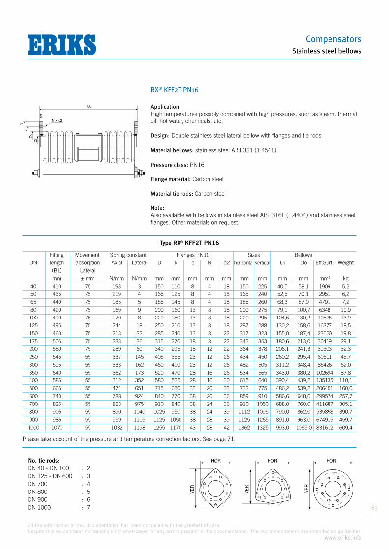
Compensators
83
All the information in this documentation has been compiled with the greatest of care.
Despite this we can bear no responsibility whatsoever for any errors present in the documentation. The recommendations are intended as guidelines.
www.eriks.info
Stainless steel bellows
RX® KFF2T PN16
Application:High temperatures possibly combined with high pressures, such as steam, thermal oil, hot water, chemicals, etc.
Design: Double stainless steel lateral bellow with flanges and tie rods
Material bellows: stainless steel AISI 321 (1.4541)
Pressure class: PN16
Flange material: Carbon steel
Material tie rods: Carbon steel
Note: Also available with bellows in stainless steel AISI 316L (1.4404) and stainless steel flanges. Other materials on request.
HOR
VE
R
HOR
VE
R
HOR
VE
R
No. tie rods:DN 40 - DN 100 : 2 DN 125 - DN 600 : 3DN 700 : 4DN 800 : 5DN 900 : 6 DN 1000 : 7
BL
Do
Di
D
N x d2
k
b
Type RX® KFF2T PN16
Fitting Movement Spring constant Flanges PN10 Sizes Bellows DN length absorption Axial Lateral D k b N d2 horizontal vertical Di Do Eff.Surf. Weight (BL) Lateral mm ± mm N/mm N/mm mm mm mm mm mm mm mm mm mm mm2 kg 40 410 75 193 3 150 110 8 4 18 150 225 40,5 58,1 1909 5,2
50 435 75 219 4 165 125 8 4 18 165 240 52,5 70,1 2951 6,2
65 440 75 185 5 185 145 8 4 18 185 260 68,3 87,9 4791 7,2
80 420 75 169 9 200 160 13 8 18 200 275 79,1 100,7 6348 10,9
100 490 75 170 8 220 180 13 8 18 220 295 104,6 130,2 10825 13,9
125 495 75 244 18 250 210 13 8 18 287 288 130,2 158,6 16377 18,5
150 460 75 213 32 285 240 13 8 22 317 323 155,0 187,4 23020 19,8
175 505 75 233 36 315 270 18 8 22 343 353 180,6 213,0 30419 29,1
200 580 75 289 60 340 295 18 12 22 364 378 206,1 241,3 39303 32,3
250 545 55 337 145 405 355 23 12 26 434 450 260,2 295,4 60611 45,7
300 595 55 333 162 460 410 23 12 26 482 505 311,2 348,4 85426 62,0
350 640 55 362 173 520 470 28 16 26 534 565 343,0 380,2 102694 87,8
400 585 55 312 352 580 525 28 16 30 615 640 390,4 439,2 135135 110,1
500 665 55 471 651 715 650 33 20 33 732 775 486,2 539,2 206451 160,6
600 740 55 788 924 840 770 38 20 36 859 910 586,6 648,6 299574 257,7
700 825 55 823 975 910 840 38 24 36 910 1050 688,0 760,0 411687 305,1
800 905 55 890 1040 1025 950 38 24 39 1112 1095 790,0 862,0 535858 390,7
900 985 55 959 1105 1125 1050 38 28 39 1125 1265 891,0 963,0 674915 459,7
1000 1070 55 1032 1198 1255 1170 43 28 42 1362 1325 993,0 1065,0 831612 609,4
Please take account of the pressure and temperature correction factors. See page 71.

Hoses and Accessories
84
All the information in this documentation has been compiled with the greatest of care.
Despite this we can bear no responsibility whatsoever for any errors present in the documentation. The recommendations are intended as guidelines.
www.eriks.info
Stainless steel bellows
RX® KSG PN16
Application:High temperatures possibly combined with high pressures, such as steam, thermal oil, hot water, chemicals, etc.
Design:Single stainless steel hinging bellow with socket or butt welds and hinges
Material bellows:Stainless steel AISI 321 (1.4541)
Pressure class:PN16
Material socket or butt welds:St. 35.8
Material tie rods:Carbon steel
Note:Also available with bellows in stainless steel AISI 316L (1.4404) and stainless steel flanges. Other materials on request.
Type RX® KSG PN16
Fitting Movement Spring Socket or butt welds Sizes Bellows DN length absorption constant D L2 S horizontal vertical Di Do Eff.Surf. Weight (BL) Angular Angular mm +/-° Nmm/° mm mm mm mm mm mm mm mm2 kg 40 300 15 2112 48,3 110 2,6 90 140 40,5 58,1 1909 3,0 40 380 20 986 48,3 110 2,6 90 140 40,5 58,1 1909 3,5 50 300 15 3682 60,3 110 2,9 100 150 52,5 70,1 2951 2,9 50 380 20 1718 60,3 110 2,9 100 150 52,5 70,1 2951 4,0 65 300 15 5012 76,1 110 2,9 115 170 68,3 87,9 4791 3,6 65 380 20 2339 76,1 110 2,9 115 170 68,3 87,9 4791 4,9 80 315 15 6078 88,9 110 3,2 130 180 79,1 100,7 6348 4,2 80 410 20 2837 88,9 110 3,2 130 180 79,1 100,7 6348 5,7 100 290 15 10339 114,3 110 3,6 175 260 104,6 130,2 10825 9,9 100 385 20 3977 114,3 110 3,6 175 260 104,6 130,2 10825 15,0 125 295 15 22540 139,7 110 4,0 200 290 130,2 158,6 16377 12,0 125 415 20 7513 139,7 110 4,0 200 290 130,2 158,6 16377 18,4 150 320 15 27634 168,3 110 4,5 230 315 155,0 187,4 23020 14,4 150 415 20 12561 168,3 110 4,5 230 315 155,0 187,4 23020 20,4 175 340 14 19846 193,7 120 5,6 275 365 180,6 213,0 30419 23,7 175 435 20 18112 193,7 120 5,6 275 365 180,6 213,0 30419 30,1
Please take account of the pressure and temperature correction factors. See page 71.
BL
Do
D Di
L2
VE
R
S

Compensators
85
All the information in this documentation has been compiled with the greatest of care.
Despite this we can bear no responsibility whatsoever for any errors present in the documentation. The recommendations are intended as guidelines.
www.eriks.info
Stainless steel bellows
RX® KSG PN16 (cont.)
Type RX® KSG PN16
Fitting Movement Spring Socket or butt welds Sizes Bellows DN length absorption constant D L2 S horizontal vertical Di Do Eff.Surf. Weight (BL) Angular Angular mm +/-° Nmm/° mm mm mm mm mm mm mm mm2 kg 200 345 14 63942 219,1 120 5,6 300 400 206,1 241,3 39303 27,2
200 445 20 29073 219,1 120 5,6 300 400 206,1 241,3 39303 34,5
250 345 11 114879 273,0 120 6,3 375 505 260,2 295,4 60611 51,6
250 480 20 44184 273,0 120 6,3 375 505 260,2 295,4 60611 72,0
300 345 10 159735 323,9 120 8,0 425 560 311,2 348,4 85426 66,8
300 515 20 53245 323,9 120 8,0 425 560 311,2 348,4 85426 94,7
350 375 9 208525 355,6 135 8,0 475 600 343,0 380,2 102694 82,4
350 545 20 69508 355,6 135 8,0 475 600 343,0 380,2 102694 111,8
400 405 10 236227 406,4 135 8,0 525 660 389,9 438,7 134809 106,6
400 585 20 91162 406,4 135 8,0 525 660 389,9 438,7 134809 142,9
450 405 9 450750 457,2 135 8,0 595 720 441,2 492,2 171067 126,6
450 540 19 204886 457,2 135 8,0 595 720 441,2 492,2 171067 163,2
500 445 11 545966 508,0 135 8,0 650 770 486,2 539,2 206451 153,3
500 615 20 248167 508,0 135 8,0 650 770 486,2 539,2 206451 193,2
550 445 10 702611 559,0 135 10,0 720 870 537,3 590,3 249655 197,1
550 560 19 390339 559,0 135 10,0 720 870 537,3 590,3 249655 222,7
600 445 7 1323663 609,6 150 10,0 790 940 586,6 648,6 299574 254,4
600 660 20 440328 609,6 150 10,0 790 940 586,6 648,6 299574 323,2
700 450 6 1904169 711,0 150 10,0 910 1060 688,0 760,0 411687 345,8
700 680 19 634723 711,0 150 10,0 910 1060 688,0 760,0 411687 461,7
800 450 5 2676643 813,0 150 10,0 1015 1160 790,0 862,0 535858 426,1
800 680 16 892214 813,0 150 10,0 1015 1160 790,0 862,0 535858 530,8
900 450 5 3625749 914,0 150 10,0 1135 1275 891,0 963,0 674915 563,4
900 680 15 1208583 914,0 150 10,0 1135 1275 891,0 963,0 674915 640,6
1000 450 4 4806809 1016,0 150 10,0 1235 1385 993,0 1065,0 831612 626,5
1000 680 13 1602270 1016,0 150 10,0 1235 1385 993,0 1065,0 831612 751,1
Please take account of the pressure and temperature correction factors. See page 71.
BL
Do
D Di
L2
VE
R
S
HOR
VE
R
HORV
ER

Hoses and Accessories
86
All the information in this documentation has been compiled with the greatest of care.
Despite this we can bear no responsibility whatsoever for any errors present in the documentation. The recommendations are intended as guidelines.
www.eriks.info
Stainless steel bellows
RX® KFFG PN16
Application:High temperatures possibly combined with high pressures, such as steam, thermal oil, hot water, chemicals, etc.
Design:Single stainless steel hinging bellow with fixed flanges and hinges
Material bellows:Stainless steel AISI 321 (1.4541)
Pressure class:PN16
Flange material:Carbon steel
Material tie rods:Carbon steel
Note:Also available with bellows in stainless steel AISI 316L (1.4404) and stainless steel flanges. Other materials and pressure classes on request.
BL
Do Di
VE
R
k
N x d2
b
Type RX® KFFG PN16
Fitting Movement Spring Flanges PN10 Sizes Bellows DN length absorption constant D k N d2 horizontal vertical Di Do Eff.Surf. Weight (BL) Angular Angular mm +/-° Nmm/° mm mm mm mm mm mm mm mm mm2 kg 40 115 15 0,8 13 110 4 18 150 267 40,5 58,1 1909 9
40 175 20 0,4 13 110 4 18 150 267 40,5 58,1 1909 9
50 115 15 1,2 13 125 4 18 165 282 52,5 70,1 2951 9
50 175 20 0,7 13 125 4 18 165 282 52,5 70,1 2951 10
65 115 15 1,6 13 145 4 18 185 302 68,3 87,9 4791 11
65 175 20 1,8 13 145 4 18 185 302 68,3 87,9 4791 12
80 115 15 4,9 13 160 8 18 200 317 79,1 100,7 6348 12
80 205 20 2,3 13 160 8 18 200 317 79,1 100,7 6348 12
100 130 15 6,4 18 180 8 18 220 342 104,6 130,2 10825 18
100 190 20 3,7 18 180 8 18 220 342 104,6 130,2 10825 19
125 140 15 7,8 18 210 8 18 250 372 130,2 158,6 16377 20
125 220 20 7,2 18 210 8 18 250 372 130,2 158,6 16377 21
150 150 15 18,9 23 240 8 22 285 412 155,0 187,4 23020 29
150 230 20 9,4 23 240 8 22 285 412 155,0 187,4 23020 30
175 165 14 19,1 23 270 8 22 315 442 180,6 213,0 30419 35
175 230 20 11,5 23 270 8 22 315 442 180,6 213,0 30419 36
Please take account of the pressure and temperature correction factors. See page 71.

Compensators
87
All the information in this documentation has been compiled with the greatest of care.
Despite this we can bear no responsibility whatsoever for any errors present in the documentation. The recommendations are intended as guidelines.
www.eriks.info
Stainless steel bellows
RX® KFFG PN16 (cont.)
BL
Do Di
VE
R
k
N x d2
b
Type RX® KFFG PN16
Fitting Movement Spring Flanges PN10 Sizes Bellows DN length absorption constant D k N d2 horizontal vertical Di Do Eff.Surf. Weight (BL) Angular Angular mm +/-° Nmm/° mm mm mm mm mm mm mm mm mm2 kg 200 165 14 36,1 28 295 12 22 340 472 206,1 241,3 39303 45
200 240 20 21,7 28 295 12 22 340 472 206,1 241,3 39303 47
250 190 11 47,8 33 355 12 26 405 582 260,2 295,4 60611 73
250 285 20 30,4 33 355 12 26 405 582 260,2 295,4 60611 78
300 210 10 78,2 38 410 12 26 460 642 311,2 348,4 85426 95
300 330 20 52,3 38 410 12 26 460 642 311,2 348,4 85426 112
350 250 9 85,5 38 470 16 26 520 702 343,0 380,2 102694 135
350 330 20 59,2 38 470 16 26 520 702 343,0 380,2 102694 142
400 275 10 106,4 43 525 16 30 580 768 389,9 438,7 134809 168
400 330 20 125,6 43 526 16 30 580 768 389,9 438,7 134809 175
500 360 11 260 53 650 20 33 715 952 486,2 539,2 206451 300
500 460 20 170 53 650 20 33 715 952 486,2 539,2 206451 32
600 400 7 660 58 770 20 36 840 1082 586,6 648,6 299574 465
600 460 20 295 58 770 20 36 840 1082 586,6 648,6 299574 475
700 430 6 952 78 840 24 36 910 1172 688,0 760,0 411687 590
700 480 19 438 78 840 24 36 910 1172 688,0 760,0 411687 615
800 580 5 1340 98 950 24 39 1025 1348 790,0 862,0 535858 1145
800 650 16 595 98 950 24 39 1025 1348 790,0 862,0 535858 1170
900 600 5 1810 108 1050 28 39 1125 1458 891,0 963,0 674915 1330
900 670 15 810 108 1050 28 39 1125 1458 891,0 963,0 674915 1350
1000 630 4 2405 118 1170 28 42 1255 1598 993,0 1065,0 831612 1620
1000 700 13 1105 118 1170 28 42 1255 1598 993,0 1065,0 831612 1650
Please take account of the pressure and temperature correction factors. See page 71.
HOR
VE
R
HOR
VE
R
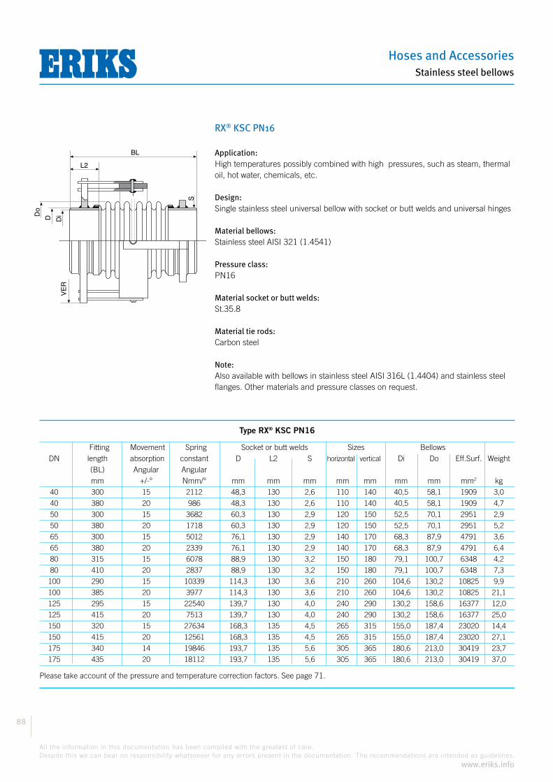
Hoses and Accessories
88
All the information in this documentation has been compiled with the greatest of care.
Despite this we can bear no responsibility whatsoever for any errors present in the documentation. The recommendations are intended as guidelines.
www.eriks.info
Stainless steel bellows
RX® KSC PN16
Application:High temperatures possibly combined with high pressures, such as steam, thermal oil, hot water, chemicals, etc.
Design:Single stainless steel universal bellow with socket or butt welds and universal hinges
Material bellows:Stainless steel AISI 321 (1.4541)
Pressure class:PN16
Material socket or butt welds:St.35.8
Material tie rods:Carbon steel
Note:Also available with bellows in stainless steel AISI 316L (1.4404) and stainless steel flanges. Other materials and pressure classes on request.
BL
Do
D Di
L2
VE
R
S
Type RX® KSC PN16
Fitting Movement Spring Socket or butt welds Sizes Bellows DN length absorption constant D L2 S horizontal vertical Di Do Eff.Surf. Weight (BL) Angular Angular mm +/-° Nmm/° mm mm mm mm mm mm mm mm2 kg 40 300 15 2112 48,3 130 2,6 110 140 40,5 58,1 1909 3,0
40 380 20 986 48,3 130 2,6 110 140 40,5 58,1 1909 4,7
50 300 15 3682 60,3 130 2,9 120 150 52,5 70,1 2951 2,9
50 380 20 1718 60,3 130 2,9 120 150 52,5 70,1 2951 5,2
65 300 15 5012 76,1 130 2,9 140 170 68,3 87,9 4791 3,6
65 380 20 2339 76,1 130 2,9 140 170 68,3 87,9 4791 6,4
80 315 15 6078 88,9 130 3,2 150 180 79,1 100,7 6348 4,2
80 410 20 2837 88,9 130 3,2 150 180 79,1 100,7 6348 7,3
100 290 15 10339 114,3 130 3,6 210 260 104,6 130,2 10825 9,9
100 385 20 3977 114,3 130 3,6 210 260 104,6 130,2 10825 21,1
125 295 15 22540 139,7 130 4,0 240 290 130,2 158,6 16377 12,0
125 415 20 7513 139,7 130 4,0 240 290 130,2 158,6 16377 25,0
150 320 15 27634 168,3 135 4,5 265 315 155,0 187,4 23020 14,4
150 415 20 12561 168,3 135 4,5 265 315 155,0 187,4 23020 27,1
175 340 14 19846 193,7 135 5,6 305 365 180,6 213,0 30419 23,7
175 435 20 18112 193,7 135 5,6 305 365 180,6 213,0 30419 37,0
Please take account of the pressure and temperature correction factors. See page 71.

Compensators
89
All the information in this documentation has been compiled with the greatest of care.
Despite this we can bear no responsibility whatsoever for any errors present in the documentation. The recommendations are intended as guidelines.
www.eriks.info
Stainless steel bellows
RX® KSC PN16 (cont.)
BL
Do
D Di
L2
VE
R
S
Type RX® KSC PN16
Fitting Movement Spring Socket or butt welds Sizes Bellows DN length absorption constant D L2 S horizontal vertical Di Do Eff.Surf. Weight (BL) Angular Angular mm +/-° Nmm/° mm mm mm mm mm mm mm mm2 kg 200 345 14 63942 219,1 135 5,6 340 400 206,1 241,3 39303 27,2
200 445 20 29073 219,1 135 5,6 340 400 206,1 241,3 39303 41,7
250 345 11 114879 273,0 140 6,3 425 505 260,2 295,4 60611 51,6
250 480 20 44184 273,0 140 6,3 425 505 260,2 295,4 60611 95,0
300 345 10 159735 323,9 160 8,0 480 560 311,2 348,4 85426 59,6
300 515 20 53245 323,9 160 8,0 480 560 311,2 348,4 85426 112,0
350 375 9 208525 355,6 160 8,0 510 600 343,0 380,2 102694 82,4
350 545 20 69508 355,6 160 8,0 510 600 343,0 380,2 102694 138,0
400 405 10 236227 406,4 175 8,0 570 660 389,9 438,7 134809 96,8
400 585 20 91162 406,4 175 8,0 570 660 389,9 438,7 134809 161,1
450 405 9 450750 457,2 180 8,0 620 720 441,2 492,2 171067 126,6
450 540 19 204886 457,2 180 8,0 620 720 441,2 492,2 171067 189,3
500 445 11 545966 508,0 220 8,0 670 770 486,2 539,2 206451 140,2
500 615 20 248167 508,0 220 8,0 670 770 486,2 539,2 206451 209,9
550 445 10 702611 559,0 220 10,0 750 870 537,3 590,3 249655 182,1
550 560 19 390339 559,0 220 10,0 750 870 537,3 590,3 249655 269,7
600 445 7 1323663 609,6 220 10,0 810 940 586,6 648,6 299574 254,4
600 660 20 440328 609,6 220 10,0 810 940 586,6 648,6 299574 378,8
700 450 6 1904169 711,0 225 10,0 920 1060 688,0 760,0 411687 345,8
700 680 19 634723 711,0 225 10,0 920 1060 688,0 760,0 411687 502,7
800 450 5 2676643 813,0 225 10,0 1020 1160 790,0 862,0 535858 397,8
800 680 16 892214 813,0 225 10,0 1020 1160 790,0 862,0 535858 579,9
900 450 5 3625749 914,0 225 10,0 1125 1275 891,0 963,0 674915 496,4
900 680 15 1208583 914,0 225 10,0 1125 1275 891,0 963,0 674915 685,0
1000 450 4 4806809 1016,0 225 10,0 1125 1385 993,0 1065,0 831612 589,3
1000 680 13 1602270 1016,0 225 10,0 1125 1385 993,0 1065,0 831612 803,8
Please take account of the pressure and temperature correction factors. See page 71.
HOR
VE
R
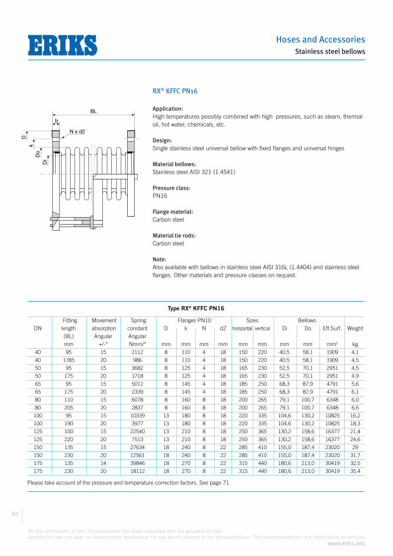
Hoses and Accessories
90
All the information in this documentation has been compiled with the greatest of care.
Despite this we can bear no responsibility whatsoever for any errors present in the documentation. The recommendations are intended as guidelines.
www.eriks.info
Stainless steel bellows
RX® KFFC PN16
Application:High temperatures possibly combined with high pressures, such as steam, thermal oil, hot water, chemicals, etc.
Design:Single stainless steel universal bellow with fixed flanges and universal hinges
Material bellows:Stainless steel AISI 321 (1.4541)
Pressure class:PN16
Flange material:Carbon steel
Material tie rods:Carbon steel
Note:Also available with bellows in stainless steel AISI 316L (1.4404) and stainless steel flanges. Other materials and pressure classes on request.
BL
Do
Di
k
N x d2
b
D
Type RX® KFFC PN16
Fitting Movement Spring Flanges PN10 Sizes Bellows DN length absorption constant D k N d2 horizontal vertical Di Do Eff.Surf. Weight (BL) Angular Angular mm +/-° Nmm/° mm mm mm mm mm mm mm mm mm2 kg 40 95 15 2112 8 110 4 18 150 220 40,5 58,1 1909 4,1
40 1785 20 986 8 110 4 18 150 220 40,5 58,1 1909 4,5
50 95 15 3682 8 125 4 18 165 230 52,5 70,1 2951 4,5
50 175 20 1718 8 125 4 18 165 230 52,5 70,1 2951 4,9
65 95 15 5012 8 145 4 18 185 250 68,3 87,9 4791 5,6
65 175 20 2339 8 145 4 18 185 250 68,3 87,9 4791 6,1
80 110 15 6078 8 160 8 18 200 265 79,1 100,7 6348 6,0
80 205 20 2837 8 160 8 18 200 265 79,1 100,7 6348 6,6
100 95 15 10339 13 180 8 18 220 335 104,6 130,2 10825 16,2
100 190 20 3977 13 180 8 18 220 335 104,6 130,2 10825 18,3
125 100 15 22540 13 210 8 18 250 365 130,2 158,6 16377 21,4
125 220 20 7513 13 210 8 18 250 365 130,2 158,6 16377 24,6
150 135 15 27634 18 240 8 22 285 410 155,0 187,4 23020 29
150 230 20 12561 18 240 8 22 285 410 155,0 187,4 23020 31,7
175 135 14 39846 18 270 8 22 315 440 180,6 213,0 30419 32,5
175 230 20 18112 18 270 8 22 315 440 180,6 213,0 30419 35,4
Please take account of the pressure and temperature correction factors. See page 71.
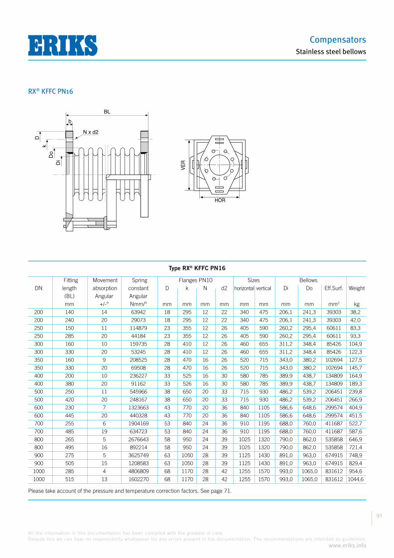
Compensators
91
All the information in this documentation has been compiled with the greatest of care.
Despite this we can bear no responsibility whatsoever for any errors present in the documentation. The recommendations are intended as guidelines.
www.eriks.info
Stainless steel bellows
RX® KFFC PN16
BL
Do
Di
k
N x d2
b
D
Type RX® KFFC PN16
Fitting Movement Spring Flanges PN10 Sizes Bellows DN length absorption constant D k N d2 horizontal vertical Di Do Eff.Surf. Weight (BL) Angular Angular mm +/-° Nmm/° mm mm mm mm mm mm mm mm mm2 kg 200 140 14 63942 18 295 12 22 340 475 206,1 241,3 39303 38,2
200 240 20 29073 18 295 12 22 340 475 206,1 241,3 39303 42,0
250 150 11 114879 23 355 12 26 405 590 260,2 295,4 60611 83,3
250 285 20 44184 23 355 12 26 405 590 260,2 295,4 60611 93,3
300 160 10 159735 28 410 12 26 460 655 311,2 348,4 85426 104,9
300 330 20 53245 28 410 12 26 460 655 311,2 348,4 85426 122,3
350 160 9 208525 28 470 16 26 520 715 343,0 380,2 102694 127,5
350 330 20 69508 28 470 16 26 520 715 343,0 380,2 102694 145,7
400 200 10 236227 33 525 16 30 580 785 389,9 438,7 134809 164,9
400 380 20 91162 33 526 16 30 580 785 389,9 438,7 134809 189,3
500 250 11 545966 38 650 20 33 715 930 486,2 539,2 206451 239,8
500 420 20 248167 38 650 20 33 715 930 486,2 539,2 206451 266,9
600 230 7 1323663 43 770 20 36 840 1105 586,6 648,6 299574 404,9
600 445 20 440328 43 770 20 36 840 1105 586,6 648,6 299574 451,5
700 255 6 1904169 53 840 24 36 910 1195 688,0 760,0 411687 522,7
700 485 19 634723 53 840 24 36 910 1195 688,0 760,0 411687 587,6
800 265 5 2676643 58 950 24 39 1025 1320 790,0 862,0 535858 646,9
800 495 16 892214 58 950 24 39 1025 1320 790,0 862,0 535858 721,4
900 275 5 3625749 63 1050 28 39 1125 1430 891,0 963,0 674915 748,9
900 505 15 1208583 63 1050 28 39 1125 1430 891,0 963,0 674915 829,4
1000 285 4 4806809 68 1170 28 42 1255 1570 993,0 1065,0 831612 954,6
1000 515 13 1602270 68 1170 28 42 1255 1570 993,0 1065,0 831612 1044,6
Please take account of the pressure and temperature correction factors. See page 71.
HOR
VE
R
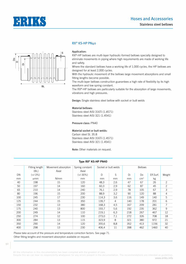
Hoses and Accessories
92
All the information in this documentation has been compiled with the greatest of care.
Despite this we can bear no responsibility whatsoever for any errors present in the documentation. The recommendations are intended as guidelines.
www.eriks.info
Stainless steel bellows
RX® KS-HP PN40
Application:®-HP bellows are multi-layer hydraulic-formed bellows specially designed to
eliminate movements in piping where high requirements are made of working life and safety. Where the standard bellows have a working life of 1,000 cycles, the HP bellows are designed for at least 2,000 cycles.With the hydraulic movement of the bellows large movement absorptions and small fitting lengths become possible.The multi-layer bellows construction guarantees a high rate of flexibility by its high waveform and low spring constant.
®-HP bellows are particularly suitable for the absorption of large movements, vibrations and high pressures.
Design: Single stainless steel bellow with socket or butt welds
Material bellows: Stainless steel AISI 316Ti (1.4571)Stainless steel AISI 321 (1.4541)
Pressure class: PN40
Material socket or butt welds:Carbon steel St. 35.8Stainless steel AISI 316Ti (1.4571)Stainless steel AISI 321 (1.4541)
Note: Other materials on request.
BL
S
Do
D
Di
Type RX® KS-HP PN40
Fitting length Movement absorption Spring constant Socket or butt welds Bellows (BL) Axial Axial DN (+/-3%) (+/-30%) D S Di Do Eff.Surf. Weight mm ±mm N/mm mm mm mm mm cm2 kg 40 198 15 120 48,3 2,6 47 67 26 2 50 197 14 160 60,3 2,9 62 87 45 2 65 210 14 240 76,1 2,9 78 105 67 3 80 196 15 200 88,9 3,2 90 120 88 4 100 245 17 230 114,3 3,6 116 149 140 5 125 244 15 350 139,7 4 140 178 201 6 150 232 13 380 168,3 4,5 167 209 281 7 175 240 13 800 193,7 5,6 192 235 362 9 200 249 14 110 219,1 6,3 218 267 467 12 250 274 12 100 273,0 7,1 272 326 708 18 300 284 13 115 323,9 8 321 380 972 21 350 290 14 120 355,6 8,8 352 413 1156 32 400 298 13 230 406,4 11 398 462 1460 40
Please take account of the pressure and temperature correction factors. See page 71.Other fitting lengths and movement absorption available on request.

Compensators
93
All the information in this documentation has been compiled with the greatest of care.
Despite this we can bear no responsibility whatsoever for any errors present in the documentation. The recommendations are intended as guidelines.
www.eriks.info
Stainless steel bellows
RX® KS-HP PN64
Application:®-HP bellows are multi-layer hydraulic-formed bellows specially designed to
eliminate movements in piping where high requirements are made of working life and safety.Where the standard bellows have a working life of 1000 cycles, the HP bellows are designed for at least 2000 cycles.With the hydraulic movement of the bellows large movement absorptions and small fitting lengths become possible.The multi-layer bellows construction guarantees a high rate of flexibility by its high waveform and low spring constant.
®-HP bellows are particularly suitable for the absorption of large movements, vibrations and high pressures.
Design: Single stainless steel bellow with socket or butt welds
Material bellows: Stainless steel AISI 316Ti (1.4571)Stainless steel AISI 321 (1.4541)
Pressure class: PN64
Material socket or butt welds:Carbon steel St. 35.8Stainless steel AISI 316Ti (1.4571)Stainless steel AISI 321 (1.4541)
Note: Other materials on request.
Type RX® KS-HP PN64
Fitting length Movement absorption Spring constant Socket or butt welds Bellows (BL) Axial Axial DN (+/-3%) (+/-30%) D S Di Do Eff.Surf. Weight mm ±mm N/mm mm mm mm mm cm2 kg 40 208 11 210 48,3 2,9 51 73 31 2 50 204 11 310 60,3 2,9 62 87 45 2 65 203 11 310 76,1 3,2 77 105 67 3 80 206 13 340 88,9 3,6 89 121 89 4 100 244 13 400 114,3 4 117 163 146 5,5 125 251 14 640 139,7 4,5 141 178 202 6 150 242 11 1300 168,3 5,6 167 209 281 7 175 250 12 1250 193,7 6,3 191 235 360 12 200 254 13 1160 219,1 7,1 216 263 455 14 250 283 12 1400 273,0 8,8 272 326 708 23 300 292 12 1550 323,9 11 321 380 972 32 350 297 13 1750 355,6 12,5 352 417 1169 53 400 346 15 2500 406,4 14,2 398 462 1460 60
Please take account of the pressure and temperature correction factors. See page 71.Other fitting lengths and movement absorption available on request.
BL
S
Do
D
Di
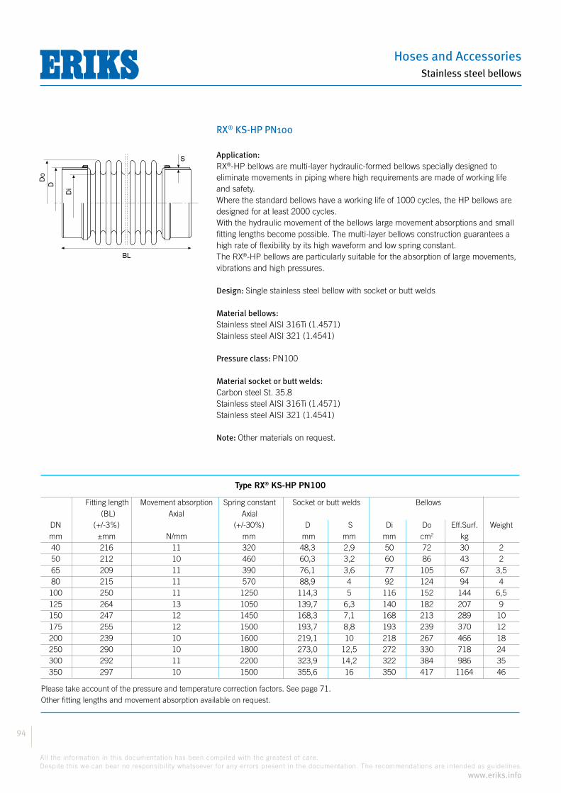
Hoses and Accessories
94
All the information in this documentation has been compiled with the greatest of care.
Despite this we can bear no responsibility whatsoever for any errors present in the documentation. The recommendations are intended as guidelines.
www.eriks.info
Stainless steel bellows
RX® KS-HP PN100
Application:®-HP bellows are multi-layer hydraulic-formed bellows specially designed to
eliminate movements in piping where high requirements are made of working life and safety.Where the standard bellows have a working life of 1000 cycles, the HP bellows are designed for at least 2000 cycles.With the hydraulic movement of the bellows large movement absorptions and small fitting lengths become possible. The multi-layer bellows construction guarantees a high rate of flexibility by its high waveform and low spring constant.
®-HP bellows are particularly suitable for the absorption of large movements, vibrations and high pressures.
Design: Single stainless steel bellow with socket or butt welds
Material bellows: Stainless steel AISI 316Ti (1.4571)Stainless steel AISI 321 (1.4541)
Pressure class: PN100
Material socket or butt welds:Carbon steel St. 35.8Stainless steel AISI 316Ti (1.4571)Stainless steel AISI 321 (1.4541)
Note: Other materials on request.
Type RX® KS-HP PN100
Fitting length Movement absorption Spring constant Socket or butt welds Bellows (BL) Axial Axial DN (+/-3%) (+/-30%) D S Di Do Eff.Surf. Weight mm ±mm N/mm mm mm mm mm cm2 kg 40 216 11 320 48,3 2,9 50 72 30 2 50 212 10 460 60,3 3,2 60 86 43 2 65 209 11 390 76,1 3,6 77 105 67 3,5 80 215 11 570 88,9 4 92 124 94 4 100 250 11 1250 114,3 5 116 152 144 6,5 125 264 13 1050 139,7 6,3 140 182 207 9 150 247 12 1450 168,3 7,1 168 213 289 10 175 255 12 1500 193,7 8,8 193 239 370 12 200 239 10 1600 219,1 10 218 267 466 18 250 290 10 1800 273,0 12,5 272 330 718 24 300 292 11 2200 323,9 14,2 322 384 986 35 350 297 10 1500 355,6 16 350 417 1164 46
Please take account of the pressure and temperature correction factors. See page 71.Other fitting lengths and movement absorption available on request.
BL
S
Do
D
Di
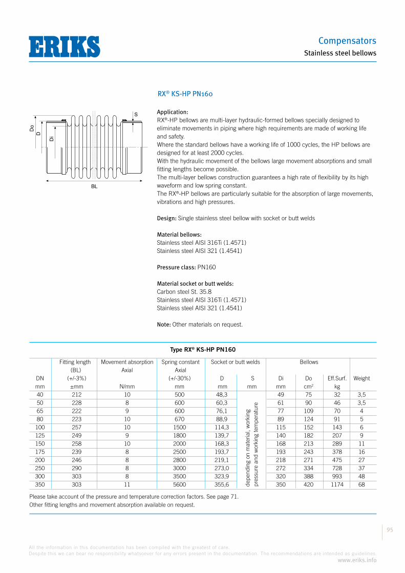
Compensators
95
All the information in this documentation has been compiled with the greatest of care.
Despite this we can bear no responsibility whatsoever for any errors present in the documentation. The recommendations are intended as guidelines.
www.eriks.info
Stainless steel bellows
RX® KS-HP PN160
Application:®-HP bellows are multi-layer hydraulic-formed bellows specially designed to
eliminate movements in piping where high requirements are made of working life and safety.Where the standard bellows have a working life of 1000 cycles, the HP bellows are designed for at least 2000 cycles.With the hydraulic movement of the bellows large movement absorptions and small fitting lengths become possible.The multi-layer bellows construction guarantees a high rate of flexibility by its high waveform and low spring constant.
®-HP bellows are particularly suitable for the absorption of large movements, vibrations and high pressures.
Design: Single stainless steel bellow with socket or butt welds
Material bellows: Stainless steel AISI 316Ti (1.4571)Stainless steel AISI 321 (1.4541)
Pressure class: PN160
Material socket or butt welds:Carbon steel St. 35.8Stainless steel AISI 316Ti (1.4571)Stainless steel AISI 321 (1.4541)
Note: Other materials on request.
BL
S
Do
D
Di
Type RX® KS-HP PN160
Fitting length Movement absorption Spring constant Socket or butt welds Bellows (BL) Axial Axial DN (+/-3%) (+/-30%) D S Di Do Eff.Surf. Weight mm ±mm N/mm mm mm mm mm cm2 kg 40 212 10 500 48,3 49 75 32 3,5 50 228 8 600 60,3 61 90 46 3,5 65 222 9 600 76,1 77 109 70 4 80 223 10 670 88,9 89 124 91 5 100 257 10 1500 114,3 115 152 143 6 125 249 9 1800 139,7 140 182 207 9 150 258 10 2000 168,3 168 213 289 11 175 239 8 2500 193,7 193 243 378 16 200 246 8 2800 219,1 218 271 475 27 250 290 8 3000 273,0 272 334 728 37 300 303 8 3500 323,9 320 388 993 48 350 303 11 5600 355,6 350 420 1174 68
Please take account of the pressure and temperature correction factors. See page 71.Other fitting lengths and movement absorption available on request.
depe
ndin
g on
mat
eria
l, w
orki
ng
pres
sure
and
wor
king
tem
pera
ture

Hoses and Accessories
96
All the information in this documentation has been compiled with the greatest of care.
Despite this we can bear no responsibility whatsoever for any errors present in the documentation. The recommendations are intended as guidelines.
www.eriks.info
Stainless steel bellows
RX® KS-HP PN250
Application:®-HP bellows are multi-layer hydraulic-formed bellows specially designed to
eliminate movements in piping where high requirements are made of working life and safety. Where the standard bellows have a working life of 1000 cycles, the HP bellows are designed for at least 2000 cycles.With the hydraulic movement of the bellows large movement absorptions and small fitting lengths become possible.The multi-layer bellows construction guarantees a high rate of flexibility by its high waveform and low spring constant.
®-HP bellows are particularly suitable for the absorption of large movements, vibrations and high pressures.
Design: Single stainless steel bellow with socket or butt welds
Material bellows: Stainless steel AISI 316Ti (1.4571)Stainless steel AISI 321 (1.4541)
Pressure class: PN250
Material socket or butt welds:Carbon steel St. 35.8Stainless steel AISI 316Ti (1.4571)Stainless steel AISI 321 (1.4541)
Note: Other materials on request.
Type RX® KS-HP PN160
Fitting length Movement absorption Spring constant Socket or butt welds Bellows (BL) Axial Axial DN (+/-3%) (+/-30%) D S Di Do Eff.Surf. Weight mm ±mm N/mm mm mm mm mm cm2 kg 40 212 10 500 48,3 49 75 32 3,5 50 228 8 600 60,3 61 90 46 3,5 65 222 9 600 76,1 77 109 70 4 80 223 10 670 88,9 89 124 91 5 100 257 10 1500 114,3 115 152 143 6 125 249 9 1800 139,7 140 182 207 9 150 258 10 2000 168,3 168 213 289 11 175 239 8 2500 193,7 193 243 378 16 200 246 8 2800 219,1 218 271 475 27 250 290 8 3000 273,0 272 334 728 37 300 303 8 3500 323,9 320 388 993 48 350 303 11 5600 355,6 350 420 1174 68
Please take account of the pressure and temperature correction factors. See page 71.Other fitting lengths and movement absorption available on request.
depe
ndin
g on
mat
eria
l, w
orki
ng
pres
sure
and
wor
king
tem
pera
ture
BL
S
Do
D
Di
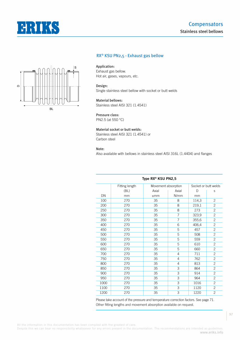
Compensators
97
All the information in this documentation has been compiled with the greatest of care.
Despite this we can bear no responsibility whatsoever for any errors present in the documentation. The recommendations are intended as guidelines.
www.eriks.info
Stainless steel bellows
RX® KSU PN2,5 - Exhaust gas bellow
Application:Exhaust gas bellow.Hot air, gases, vapours, etc.
Design:Single stainless steel bellow with socket or butt welds
Material bellows:Stainless steel AISI 321 (1.4541)
Pressure class:PN2.5 (at 550 °C)
Material socket or butt welds:Stainless steel AISI 321 (1.4541) orCarbon steel
Note:Also available with bellows in stainless steel AISI 316L (1.4404) and flanges
BL
S
D
Type RX® KSU PN2,5
Fitting length Movement absorption Socket or butt welds (BL) Axial Axial D s DN mm ±mm N/mm mm 100 270 35 8 114,3 2 200 270 35 8 219,1 2 250 270 35 8 273 2 300 270 35 7 323,9 2 350 270 35 7 355,6 2 400 270 35 6 406,4 2 450 270 35 5 457 2 500 270 35 5 508 2 550 270 35 5 559 2 600 270 35 5 610 2 650 270 35 5 660 2 700 270 35 4 711 2 750 270 35 4 762 2 800 270 35 4 813 2 850 270 35 3 864 2 900 270 35 3 914 2 950 270 35 3 964 2 1000 270 35 3 1016 2 1100 270 35 3 1120 2 1200 270 35 3 1220 2
Please take account of the pressure and temperature correction factors. See page 71.Other fitting lengths and movement absorption available on request.

Hoses and Accessories
98
All the information in this documentation has been compiled with the greatest of care.
Despite this we can bear no responsibility whatsoever for any errors present in the documentation. The recommendations are intended as guidelines.
www.eriks.info
Stainless steel bellows
Question list for metal bellows
When choosing metal bellows it is important to know the operating conditions. A question list is included below to facilitate analysing the most important information.If you submit a completed copy of this list with your enquiry or order this will help in arriving at the right choice.
Company: ................................................................................ Contact person: ...............................................................................
Address: ................................................................................ ................................................................................ ............................
Telephone: ..................................................... Enquiry/projects: ................................................. Date: ...............................................
Required number of bellows: .......................................................................................................................................................
Operating conditionsMedium: Movement:
Composition and nature: ......................................................... Axial compression: ........................................................
Temperature of medium: ......................................................... Axial elongation: ........................................................
Pressure of the medium: ........................................................ Lateral plus: ........................................................
Pressure changes: ........................................................ Lateral min: ........................................................
Temperature of environment: ........................................................ Angular movement: ........................................................
Flow speed: ........................................................ Frequency: ........................................................
Size:
Nominal passage: ............................................................................
Nominal length: ............................................................................
connections: ............................................................................
Is the pipe insulated? ............................................................................ yes/no
Material: .............................................................................
Bellows: .............................................................................
connections: .............................................................................
Remarks:........................................................................................................................................................................................................................................................................................................................................................................................................................................................................................................................................................................................................................................................................................................................................................................................................................................................................................................................................................................................................................................................................................................................................................................................................................................................................................................................................................................................................................................................................................................................................................................................................................................................................................
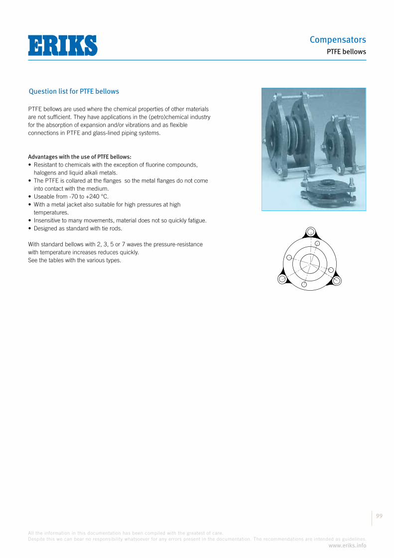
Compensators
99
All the information in this documentation has been compiled with the greatest of care.
Despite this we can bear no responsibility whatsoever for any errors present in the documentation. The recommendations are intended as guidelines.
www.eriks.info
PTFE bellows
Question list for PTFE bellows
PTFE bellows are used where the chemical properties of other materials are not sufficient. They have applications in the (petro)chemical industry for the absorption of expansion and/or vibrations and as flexible connections in PTFE and glass-lined piping systems.
Advantages with the use of PTFE bellows:
halogens and liquid alkali metals.
into contact with the medium.
temperatures.
With standard bellows with 2, 3, 5 or 7 waves the pressure-resistance with temperature increases reduces quickly. See the tables with the various types.
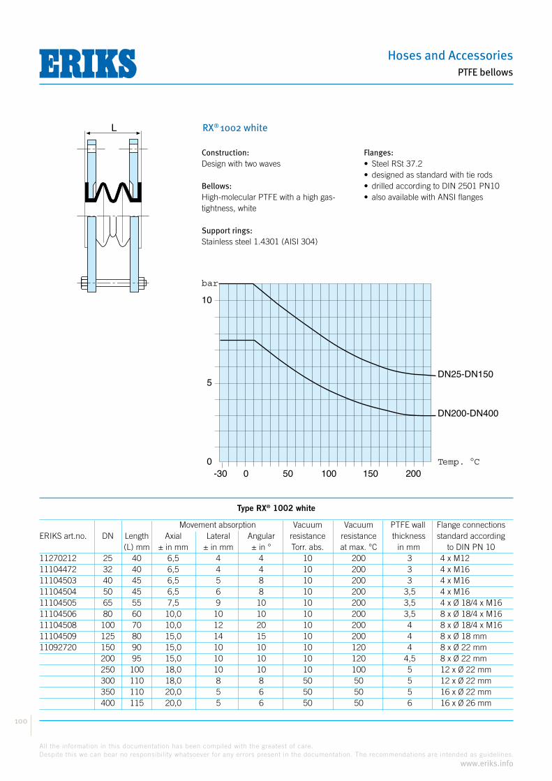
Hoses and Accessories
100
All the information in this documentation has been compiled with the greatest of care.
Despite this we can bear no responsibility whatsoever for any errors present in the documentation. The recommendations are intended as guidelines.
www.eriks.info
PTFE bellows
RX® 1002 white
Construction:Design with two waves
Bellows:High-molecular PTFE with a high gas-tightness, white
Support rings:Stainless steel 1.4301 (AISI 304)
Flanges:
Type RX® 1002 white
Movement absorption Vacuum Vacuum PTFE wall Flange connectionsERIKS art.no. DN Length Axial Lateral Angular resistance resistance thickness standard according (L) mm ± in mm ± in mm ± in ° Torr. abs. at max. °C in mm to DIN PN 1011270212 25 40 6,5 4 4 10 200 3 4 x M1211104472 32 40 6,5 4 4 10 200 3 4 x M1611104503 40 45 6,5 5 8 10 200 3 4 x M1611104504 50 45 6,5 6 8 10 200 3,5 4 x M1611104505 65 55 7,5 9 10 10 200 3,5 4 x Ø 18/4 x M1611104506 80 60 10,0 10 10 10 200 3,5 8 x Ø 18/4 x M1611104508 100 70 10,0 12 20 10 200 4 8 x Ø 18/4 x M1611104509 125 80 15,0 14 15 10 200 4 8 x Ø 18 mm11092720 150 90 15,0 10 10 10 120 4 8 x Ø 22 mm 200 95 15,0 10 10 10 120 4,5 8 x Ø 22 mm 250 100 18,0 10 10 10 100 5 12 x Ø 22 mm 300 110 18,0 8 8 50 50 5 12 x Ø 22 mm 350 110 20,0 5 6 50 50 5 16 x Ø 22 mm 400 115 20,0 5 6 50 50 6 16 x Ø 26 mm
bar
10
5
00 50 100 150 200-30
DN25-DN150
DN200-DN400
Temp. C
L

Compensators
101
All the information in this documentation has been compiled with the greatest of care.
Despite this we can bear no responsibility whatsoever for any errors present in the documentation. The recommendations are intended as guidelines.
www.eriks.info
PTFE bellows
RX® 1002 black
Construction:Design with two waves
Bellows:High-molecular PTFE with a high gas-tightness, white
Support rings:Stainless steel 1.4301 (AISI 304)
Flanges:
Type RX® 1002 black
Movement absorption Vacuum Vacuum PTFE wall Flange connectionsERIKS art.no. DN Length Axial Lateral Angular resistance resistance thickness standard according (L) mm ± in mm ± in mm ± in ° Torr. abs. at max. °C in mm to DIN PN 10 25 40 6,5 4 4 10 200 3 4 x M12 32 40 6,5 4 4 10 200 3 4 x M16 40 45 6,5 5 8 10 200 3 4 x M16 50 45 6,5 6 8 10 200 3,5 4 x M16 65 55 7,5 9 10 10 200 3,5 4 x Ø 18/4 x M16 80 60 10,0 10 10 10 200 3,5 8 x Ø 18/4 x M16 100 70 10,0 12 20 10 200 4 8 x Ø 18/4 x M16 125 80 15,0 14 15 10 200 4 8 x Ø 18 mm11069439 150 90 15,0 10 10 10 120 4 8 x Ø 22 mm 200 95 15,0 10 10 10 120 4,5 8 x Ø 22 mm 250 100 18,0 10 10 10 100 5 12 x Ø 22 mm 300 110 18,0 8 8 50 50 5 12 x Ø 22 mm11068924 350 110 20,0 5 6 50 50 5 16 x Ø 22 mm 400 115 20,0 5 6 50 50 6 16 x Ø 26 mm
bar
10
5
00 50 100 150 200-30
DN25-DN150
DN200-DN400
Temp. C
L
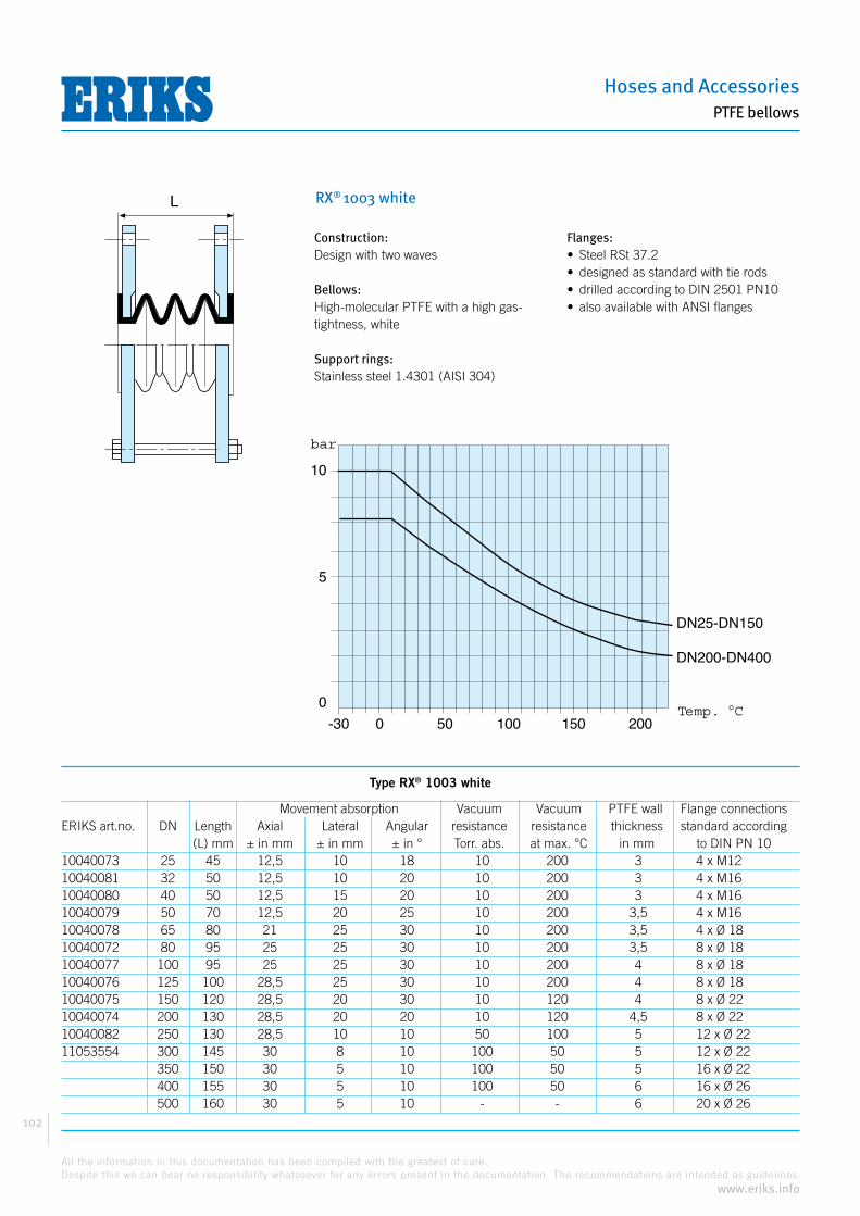
Hoses and Accessories
102
All the information in this documentation has been compiled with the greatest of care.
Despite this we can bear no responsibility whatsoever for any errors present in the documentation. The recommendations are intended as guidelines.
www.eriks.info
PTFE bellows
RX® 1003 white
Construction:Design with two waves
Bellows:High-molecular PTFE with a high gas-tightness, white
Support rings:Stainless steel 1.4301 (AISI 304)
Flanges:
Type RX® 1003 white
Movement absorption Vacuum Vacuum PTFE wall Flange connectionsERIKS art.no. DN Length Axial Lateral Angular resistance resistance thickness standard according (L) mm ± in mm ± in mm ± in ° Torr. abs. at max. °C in mm to DIN PN 1010040073 25 45 12,5 10 18 10 200 3 4 x M1210040081 32 50 12,5 10 20 10 200 3 4 x M1610040080 40 50 12,5 15 20 10 200 3 4 x M1610040079 50 70 12,5 20 25 10 200 3,5 4 x M1610040078 65 80 21 25 30 10 200 3,5 4 x Ø 1810040072 80 95 25 25 30 10 200 3,5 8 x Ø 1810040077 100 95 25 25 30 10 200 4 8 x Ø 1810040076 125 100 28,5 25 30 10 200 4 8 x Ø 18 10040075 150 120 28,5 20 30 10 120 4 8 x Ø 22 10040074 200 130 28,5 20 20 10 120 4,5 8 x Ø 2210040082 250 130 28,5 10 10 50 100 5 12 x Ø 22 11053554 300 145 30 8 10 100 50 5 12 x Ø 22 350 150 30 5 10 100 50 5 16 x Ø 22 400 155 30 5 10 100 50 6 16 x Ø 26 500 160 30 5 10 - - 6 20 x Ø 26
bar
10
5
0
0 50 100 150 200-30
DN25-DN150
DN200-DN400
Temp. C
L
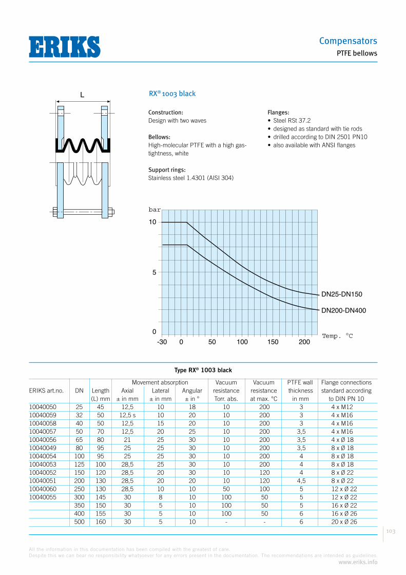
Compensators
103
All the information in this documentation has been compiled with the greatest of care.
Despite this we can bear no responsibility whatsoever for any errors present in the documentation. The recommendations are intended as guidelines.
www.eriks.info
PTFE bellows
RX® 1003 black
Construction:Design with two waves
Bellows:High-molecular PTFE with a high gas-tightness, white
Support rings:Stainless steel 1.4301 (AISI 304)
Flanges:
Type RX® 1003 black
Movement absorption Vacuum Vacuum PTFE wall Flange connectionsERIKS art.no. DN Length Axial Lateral Angular resistance resistance thickness standard according (L) mm ± in mm ± in mm ± in ° Torr. abs. at max. °C in mm to DIN PN 1010040050 25 45 12,5 10 18 10 200 3 4 x M1210040059 32 50 12,5 s 10 20 10 200 3 4 x M1610040058 40 50 12,5 15 20 10 200 3 4 x M1610040057 50 70 12,5 20 25 10 200 3,5 4 x M1610040056 65 80 21 25 30 10 200 3,5 4 x Ø 1810040049 80 95 25 25 30 10 200 3,5 8 x Ø 1810040054 100 95 25 25 30 10 200 4 8 x Ø 1810040053 125 100 28,5 25 30 10 200 4 8 x Ø 18 10040052 150 120 28,5 20 30 10 120 4 8 x Ø 22 10040051 200 130 28,5 20 20 10 120 4,5 8 x Ø 2210040060 250 130 28,5 10 10 50 100 5 12 x Ø 22 10040055 300 145 30 8 10 100 50 5 12 x Ø 22 350 150 30 5 10 100 50 5 16 x Ø 22 400 155 30 5 10 100 50 6 16 x Ø 26 500 160 30 5 10 - - 6 20 x Ø 26
bar
10
5
0
0 50 100 150 200-30
DN25-DN150
DN200-DN400
Temp. C
L
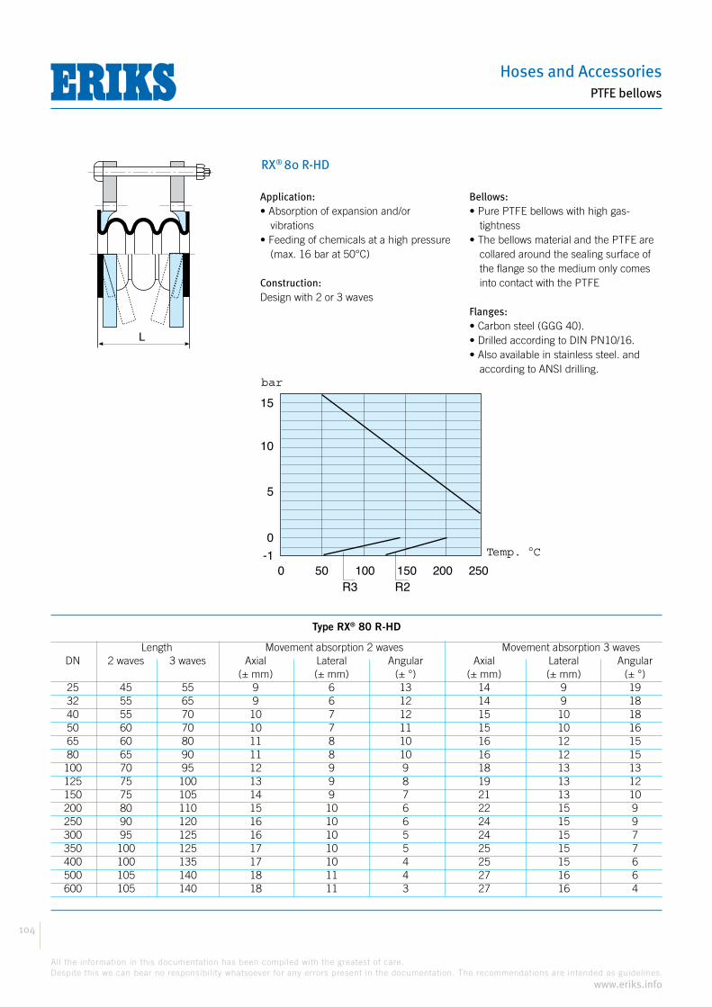
Hoses and Accessories
104
All the information in this documentation has been compiled with the greatest of care.
Despite this we can bear no responsibility whatsoever for any errors present in the documentation. The recommendations are intended as guidelines.
www.eriks.info
PTFE bellows
RX® 80 R-HD
Application:
vibrations
(max. 16 bar at 50°C)
Construction:Design with 2 or 3 waves
Bellows:
tightness
collared around the sealing surface of the flange so the medium only comes into contact with the PTFE
Flanges:
according to ANSI drilling.
Temp. C
0 50 100 150
0
5
10
15
200 250
bar
-1
R3 R2
L
Type RX® 80 R-HD
Length Movement absorption 2 waves Movement absorption 3 waves DN 2 waves 3 waves Axial Lateral Angular Axial Lateral Angular (± mm) (± mm) (± °) (± mm) (± mm) (± °) 25 45 55 9 6 13 14 9 19 32 55 65 9 6 12 14 9 18 40 55 70 10 7 12 15 10 18 50 60 70 10 7 11 15 10 16 65 60 80 11 8 10 16 12 15 80 65 90 11 8 10 16 12 15 100 70 95 12 9 9 18 13 13 125 75 100 13 9 8 19 13 12 150 75 105 14 9 7 21 13 10 200 80 110 15 10 6 22 15 9 250 90 120 16 10 6 24 15 9 300 95 125 16 10 5 24 15 7 350 100 125 17 10 5 25 15 7 400 100 135 17 10 4 25 15 6 500 105 140 18 11 4 27 16 6 600 105 140 18 11 3 27 16 4

Compensators
105
All the information in this documentation has been compiled with the greatest of care.
Despite this we can bear no responsibility whatsoever for any errors present in the documentation. The recommendations are intended as guidelines.
www.eriks.info
PTFE bellows
RX® 902
Application:Design with two waves
Bellows:White PTFE bellows of high-molecular PTFE with high gas-tightness
Support rings:Stainless steel 1.4301 (AISI 304)
Flanges:
flanges or ANSI flanges.
-30
DN 15-100
Temp. C
0 50 100 150 200
105Pa
DN 125-150
DN200-250
DN300-600
0
2
4
6
8
10
12
14
L
Type RX® 902
Movement absorption Vacuum-resistant at DN Length Axial Lateral Angular 104 Pa max. °C 104 Pa max. °C (L) mm ± in mm ± in mm ± in ° 15 28 4 2 7 0,1 200 20 28 4 2 7 0,1 200 25 35 6 3 7 0,1 200 32 35 6 3 7 0,1 200 40 35 6 3 7 0,1 200 50 40 6 3 7 0,1 200 65 57 9 5 7 0,1 200 80 57 9 5 7 0,1 200 100 67 13 6 7 0,1 200 125 83 13 6 7 0,1 150 150 75 13 6 7 0,1 150 200 102 13 6 7 0,1 50 2,0 150 250 140 15 6 7 0,7 45 3,4 100 300 150 20 10 7 1,5 45 6,7 100 350 160 20 10 7 1,5 45 6,7 100 400 178 25 10 7 1,5 45 6,7 100 450 185 25 10 7 3,4 45 7,0 100 500 230 25 10 7 8,0 100 8,7 100
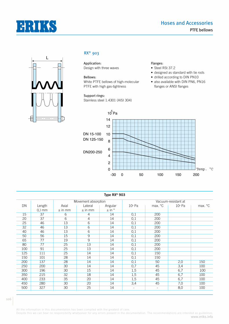
Hoses and Accessories
106
All the information in this documentation has been compiled with the greatest of care.
Despite this we can bear no responsibility whatsoever for any errors present in the documentation. The recommendations are intended as guidelines.
www.eriks.info
PTFE bellows
RX® 903
Application:Design with three waves
Bellows:White PTFE bellows of high-molecular PTFE with high gas-tightness
Support rings:Stainless steel 1.4301 (AISI 304)
Flanges:
flanges or ANSI flanges
-30
DN 15-100
Temp. C
0 50 100 150 200
105Pa
DN 125-150
DN200-250
0
2
4
6
8
10
12
14
L
Type RX® 903
Movement absorption Vacuum-resistant at DN Length Axial Lateral Angular 104 Pa max. °C 104 Pa max. °C (L) mm ± in mm ± in mm ± in ° 15 37 6 4 14 0,1 200 20 37 6 4 14 0,1 200 25 46 13 6 14 0,1 200 32 46 13 6 14 0,1 200 40 46 13 6 14 0,1 200 50 56 15 9 14 0,1 200 65 77 19 9 14 0,1 200 80 77 25 13 14 0,1 200 100 91 25 13 14 0,1 200 125 111 25 14 14 0,1 150 150 101 28 14 14 0,1 150 200 137 28 14 14 0,1 50 2,0 150 250 200 30 14 14 0,7 45 3,4 100 300 196 30 15 14 1,5 45 6,7 100 350 215 32 18 14 1,5 45 6,7 100 400 233 35 20 14 1,5 45 6,7 100 450 280 30 20 14 3,4 45 7,0 100 500 327 30 25 14 - - 8,0 100

Compensators
107
All the information in this documentation has been compiled with the greatest of care.
Despite this we can bear no responsibility whatsoever for any errors present in the documentation. The recommendations are intended as guidelines.
www.eriks.info
PTFE bellows
RX® 905
Application:Design with five waves
Bellows:White PTFE bellows of high-molecular PTFE with high gas-tightness
Support rings:Stainless steel 1.4301 (AISI 304)
Flanges:
flanges or ANSI flanges
Type RX® 905
Movement absorption Vacuum-resistant DN Length Axial Lateral Angular (L) mm ± in mm ± in mm ± in ° 15 55 8 5 20 20 55 8 5 20 25 68 8 12 20 32 68 8 12 20 40 80 13 12 20 50 88 19 12 20 65 113 25 13 20 80 113 25 16 20 Not recommended 100 139 25 16 20 125 167 32 16 20 150 153 32 16 20 200 207 32 16 20 250 300 32 16 20 300 288 35 18 20 350 325 35 18 20 400 343 40 25 20 450 470 40 25 20 500 520 40 25 20
-30
DN 15-100
Temp. C
0 50 100 150 200
105Pa
DN 125-150
DN200-250
0
2
4
6
8
10
12
14
L

Hoses and Accessories
108
All the information in this documentation has been compiled with the greatest of care.
Despite this we can bear no responsibility whatsoever for any errors present in the documentation. The recommendations are intended as guidelines.
www.eriks.info
PTFE bellows
RX® 954 PN16
Application:
pressure is combined with a high temperature or optimal safety provisions are required
use in constructions as lateral or hinging bellow
Construction:Metal bellow interior PTFE lining
Bellows:
PTFE, with rotating flanges
collared around the sealing surface of the flange so the medium only comes into contact with the PTFE
available
Flanges:
BL
b
Db
Di
Da
meerlagige balg
PTFE-bekleding
Type RX® 954 PN16
Movement absorption Spring Flanges PN16 Bellows DN Axial Length constant Standard Db b Di Da Eff. Surf. ± in mm (L) mm N/mm mm mm mm mm cm2 40 10 130 40 74 19 48 72 28 40 14 220 80 74 19 48 72 28 50 10 130 90 92 21 63 90 48 50 15 210 80 92 21 63 90 48 65 10 125 90 112 21 78 109 71 65 18 205 70 112 21 78 109 71 80 10 115 100 126 23 93 125 94 80 17 200 70 126 23 93 125 94 100 10 125 130 155 23 115 152 143 100 19 195 70 155 23 115 152 143 125 11 145 120 184 26 140 182 207 125 17 210 100 184 26 140 182 207 150 11 200 140 215 27 167 213 287 150 16 275 120 215 27 167 213 287 200 12 225 160 273 30 218 271 475 200 17 320 170 273 30 218 271 475 250 11 215 290 332 32 271 330 716 250 19 300 170 332 32 271 330 716
PN
16 o
r ac
cord
ing
to s
peci
ficat
ions
multi-layered bellow
PTFE lining

Compensators
109
All the information in this documentation has been compiled with the greatest of care.
Despite this we can bear no responsibility whatsoever for any errors present in the documentation. The recommendations are intended as guidelines.
www.eriks.info
PTFE bellows
RX® 958 PN25
Application:
pressure is combined with a high temperature or optimal safety provisions are required
use in constructions as lateral or hinging bellow
Construction:Metal bellow interior PTFE lining
Bellows:
PTFE, with rotating flanges
collared around the sealing surface of the flange so the medium only comes into contact with the PTFE
available
Flanges:
Type RX® 958 PN25
Movement absorption Spring Flanges PN16 Bellows DN Axial Length constant Standard Db b Di Da Eff. Surf. ± in mm (L) mm N/mm mm mm mm mm cm2 40 8 140 85 74 21 47 72 26 40 14 225 75 74 21 47 72 26 50 9 140 140 92 23 62 90 47 50 15 210 80 92 23 62 90 47 65 9 135 140 112 25 78 109 71 65 15 220 100 112 25 78 109 71 80 10 145 120 126 27 92 124 92 80 16 215 110 126 27 92 124 92 100 9 145 180 155 28 115 152 143 100 15 225 130 155 28 115 152 143 125 10 165 200 184 31 139 182 206 125 16 255 140 184 31 139 182 206 150 9 185 230 215 34 166 213 286 150 15 270 200 215 34 166 213 286 200 10 210 270 273 37 217 271 473 200 14 305 230 273 37 217 271 473 250 9 235 400 332 40 270 330 715 250 15 335 290 332 40 270 330 715
PN
16 o
r ac
cord
ing
to s
peci
ficat
ions
BL
b
Db
Di
Da
meerlagige balg
PTFE-bekleding
multi-layered bellow
PTFE lining

Hoses and Accessories
110
All the information in this documentation has been compiled with the greatest of care.
Despite this we can bear no responsibility whatsoever for any errors present in the documentation. The recommendations are intended as guidelines.
www.eriks.info
PTFE bellows
RX® 959
Construction:Two-part bellow, specifically for vacuum applications
Bellows:White PTFE bellows of high-molecular PTFE with high gas-tightness
Flanges:
Type RX® 959
DN Length Movement absorption D (L) mm axial in ± mm mm 100 95 10 285 150 100 15 350 200 105 15 410 250 110 18 465 300 115 18 520 350 120 18 590 400 135 20 670 450 150 20 695 500 150 20 770 600 165 12 890
L
D DN DN

Compensators
111
All the information in this documentation has been compiled with the greatest of care.
Despite this we can bear no responsibility whatsoever for any errors present in the documentation. The recommendations are intended as guidelines.
www.eriks.info
Fabric bellows
The safe connection: fabric bellows from Frenzelit
ExperienceThe Frenzelit factories were established more than 100 years ago, then already specialised in the manufacture of technical raw materials for sealing and insulation.There are now three factories with a total of 600 employees. The first bellows were constructed by Frenzelit in the fifties, then supplying a solution for complicated and unsafe connections.Now fifty years of experience guarantees exceptional quality and safety for constructions, materials and the manufacture and assembly of fabric bellows. The wide development activities at the Frenzelit factories have resulted in major advances in materials technology for the manufacture of fabric bellows, with their own high quality fabrics of glass, ceramic or aramide fibres meeting the requirements of today’s market.
Quality assuredFor each installed bellow we also share responsibility for the operational safety of your installation: this is why materials and processing are separately and continuously controlled.Each finished bellow is verified for correct sizing.Manufacturer’s certificates according to DIN 50049 are also supplied on request.
GuaranteeThe Frenzelit factories offer guarantees for each fabric bellow supplied.The guarantee supplied depends on the selected materials and the design of the bellow.A guarantee request must be mentioned with the enquiry. The guarantee does require that your information corresponds with the actual operating conditions and the assembly and manufacturer’s instructions are respected.

Hoses and Accessories
112
All the information in this documentation has been compiled with the greatest of care.
Despite this we can bear no responsibility whatsoever for any errors present in the documentation. The recommendations are intended as guidelines.
www.eriks.info
Fabric bellows
The safe connection: fabric bellows from Frenzelit
Fabric bellowsFabric bellows are used across all industry, mainly for the transport of cold and hot air or gases.Application with flue gas installations; in aeration and de-aeration, piping for air and spent gases from boilers and turbines, dryers, exhausts, ventilators and other equipment.
The advantages are:
CharacteristicsFabric bellows must be able to withstand the operating conditions to which the installation part or the pipe itself is exposed with the retention of operating reliability. The movements and vibrations occurring, both axial and lateral, must be absorbed.With their construction of various fabric layers, fabric bellows have the greatest possible flexibility to 90% axially and 35% laterally from the fitted height.The advantage here is that with long piping fewer bellows are required than with axial bellows of e.g. metal or rubber.Fabric bellows also have the advantage of a thermally insulating effect, so the deterioration of flanges and piping parts as a result of the formation of condensation can be prevented. These bellows also have a noise-insulating effect.The low bellow weight, the low resistance to axial and lateral distortion and application with low piping pressures mean piping supports, fixed points, foundations, etc. can be made relatively light. The low weight also considerably eases assembly.
DesignsThe sizes and operating conditions for fabric bellows are so application-specific that no standard designs exist. There are many construction options as regards shape, connection ends and choice of fabric and foil materials.Fabric bellows are manufactured individually for each application in any required model (round, square, rectangular, oval, conical, from. round to square, etc.) and in any size.One of the most important conditions for the optimal design of fabric bellows is correct and complete details from the user concerning the overall sizes, the pressures and temperatures occurring, the nature of the transported medium and the movements occurring during operation.Hence, at the end of this section there is a comprehensive question list that can serve as an excellent guide for the choice of bellow. With difficult or complex applications, despite the information in this manual you may still have insufficient information for choosing the right design. Our technicians will then be prepared to study the possibilities with you on-site to determine your optimum solution.
ReliabilityThe life and the operating reliability of fabric bellows are largely determined by construction and material choice. This is why materials used and manufacturing processes are regularly controlled.The manufactured bellows are also meticulously checked for final dimensions before they leave the plant.Specifications for test procedures have been drawn up in close cooperation with TÜV. Using special equipment the temperature, pressure and movement of the bellow can be simulated in changing conditions.This advanced test method applied as standard with bellows for nuclear power stations demonstrates the high quality level of the manufacturing process.
Compensators
113
All the information in this documentation has been compiled with the greatest of care.
Despite this we can bear no responsibility whatsoever for any errors present in the documentation. The recommendations are intended as guidelines.
www.eriks.info
Fabric bellows
The safe connection: fabric bellows from Frenzelit
Design choiceThe existing construction of the installation and the required technical capabilities of the bellow largely determine the type to choose. A summary of the most used types is provided on page 120.
FasteningRound and oval bellows without flanges are fixed with large hose clips. These clips can be supplied in different sizes depending on the pressure, temperature and diameter. Round and rectangular bellows with fabric flanges are fixed using separate steel flanges.Rectangular models without flanges are assembled with steel strips.The width and thickness of the steel flanges and strips must be adapted to the sizes of the fabric flanges. To prevent damage to the bellow the steel flanges and fixing attachments must be well rounded.The bolt heads must always face the bellow side. Bolts with countersunk heads are recommended for bellows subjected to large movements or that are quite round. The centre-to-centre distance between the bolts depends on the operating pressure, the flange thickness of the bellow and the sizes of the steel assembly flanges or clamping strips.Guidelines are given in the table below:
The tightening of the fastening bolts
Pressure differencesFabric bellows are constructed for both overpressure and underpressure applications. The manufacture of fabric bellows that can be kept under pressure for a long period has become possible by using modern fabric materials. The operating temperature influences the extent of pressure-resistance.
AccessoriesBesides the fabric bellow itself supplementary materials can also be supplied. This can include insulating material in the form of mineral wool, ceramic wool or silicate wool and associated reinforcement in stainless steel, clamping strips, adhesives for hypalon, neoprene and silicon rubber.Steel work can also be supplied.
Available in steel or stainless steel(304, 316L, etc.)
Gas flow guidesGas flow guides are used for the protection of the bellow against wear and against direct contact of the fabric with hot gases.Gas flow guides are also often used for technical flow reasons. With inner insulation the gas flow guides also keep the insulating material enclosed.If the piping cannot be constructed with axial movement it is advised to fit the gas flow guide with a flange. If this is not possible and the gas flow guide is not fitted removable in the pipe, the fabric bellow must not be supplied endless. This must then be made endless during assembly. Then, after assembly layer after layer of the fabric is enclosed by special attachment techniques.In this case the bellow is supplied with pre-processed layer ends.
Flange width 30 40 50 60 70 80 90
Flange thickness 6 8 8 10 12 12 12
Bolt hole dist. 60 80 100 100 120 120 120
Bolts M. 8 10 10 12 12 16 16
Operating temperatureThe operating temperature largely determines the choice of the materials to be used.Fabric bellows can be used for temperatures of -60 °C to +1,200 °C.Brief, slightly higher peak temperatures can also be withstood.The higher temperature resistance of the bellow requires more expensive material. When making an enquiry therefore mention the actually occurring temperatures.At temperatures above 500 °C internal insulation is required for the protection of the bellow.

Hoses and Accessories
114
All the information in this documentation has been compiled with the greatest of care.
Despite this we can bear no responsibility whatsoever for any errors present in the documentation. The recommendations are intended as guidelines.
www.eriks.info
Fabric bellows
The safe connection: fabric bellows from Frenzelit
Movements
Axial movementThe maximum axial movement for a fabric bellow depends on a number of factors:
circumstances require this)
Lateral movementBesides length changes fabric bellows can also simultaneously accommodate lateral/radial or angular movements.This movement capability depends on the free space between the piping or the presence of a gas flow guide or interior insulation.
Fixed pointsThe extent of the movements a fabric bellow can absorb depends on the distance and location of the fixed points with respect to the bellow.Depending on the type of fabric, bellows can compensate larger axial and lateral movements. With fabric bellows the spring constant (resistance to compression) does not have to be taken into account.Supporting and guide points allow a controlled movement of the pipe ends. Because fabric bellows by the nature of their construction are not supporting parts, mechanical stress must be avoided.
Inbouwhoogte
+
- a
Axial movement Lateral movement Angular movementTorsion
Fitted height

Compensators
115
All the information in this documentation has been compiled with the greatest of care.
Despite this we can bear no responsibility whatsoever for any errors present in the documentation. The recommendations are intended as guidelines.
www.eriks.info
Fabric bellows
The safe connection: fabric bellows from Frenzelit
MaterialsFabric bellows are made up of a number of fabric layers with impregnation. The special combination of the different material properties enables the construction of a both technically and economically optimal fabric bellow. Very high quality, expensive materials are only then used if special precautionary measures so require. Ordinarily the combination possibilities are determined by the resistance of the selected materials to operating and peak temperatures and chemical and mechanical strength.
resistance to max. 450 °C
temperature resistance to max. 1000 °C, increased tensile strength with core fibres of chrome steel
particularly high tensile strength, good chemical resistance, particularly resistant to wear and cracking, temperature resistance to max. 300 °C
max. 1000 °C, excellent chemical resistance
temperature resistance to max. 800 °C
temperature resistance to max. 1000 °C
Layer structure
of the bellows
These fabric materials are used as standard in bellows.
In fabric bellows the fabric layers alternate with layers of sealed foil. These foil layers give the fabric bellow its gas-tightness. The foil materials must obviously also be resistant to the medium and operating temperature. Foil materials can consist of rubber, plastic, PTFE and many other materials to even inconel foil.
The fabric layers on the interior of the foil have the purpose of protecting the foil against the worst heat of the medium.At underpressure these fabric layers must obviously have a certain strength against being compressed to be able to support the foil layers.
The outer fabric layer has the main purpose of resisting the internal medium pressure. This fabric layer is protected by impregnation against mechanical damage and unfavourable ambient influences.The outer fabric layer normally has no sealing purposes.
With fabric bellows the component fabric and foil layers are only adhered in the flange ends by gluing - this to allow free movement of the layers with respect to each other and guarantee a large degree of flexibility.
In exceptional cases however complete gluing of the layers can be required.
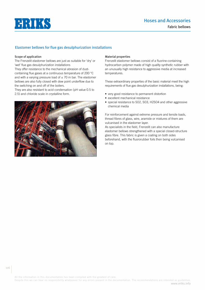
Hoses and Accessories
116
All the information in this documentation has been compiled with the greatest of care.
Despite this we can bear no responsibility whatsoever for any errors present in the documentation. The recommendations are intended as guidelines.
www.eriks.info
Fabric bellows
Elastomer bellows for flue gas desulphurization installations
Scope of applicationThe Frenzelit elastomer bellows are just as suitable for ‘dry’ or ‘wet’ flue gas desulphurization installationsThey offer resistance to the mechanical abrasion of dust-containing flue gases at a continuous temperature of 200 °C and with a varying pressure load of ± 70 m bar. The elastomer bellows are also fully closed with dew point underflow due to the switching on and off of the boilers.They are also resistant to acid condensation (pH value 0.5 to 2.5) and chloride scale in crystalline form.
Material propertiesFrenzelit elastomer bellows consist of a fluorine-containing hydrocarbon polymer made of high quality synthetic rubber with an unusually high resistance to aggressive media at increased temperatures.
These extraordinary properties of the basic material meet the high requirements of flue gas desulphurization installations, being:
chemical media
For reinforcement against extreme pressure and tensile loads, thread fibres of glass, wire, aramide or mixtures of them are vulcanised in the elastomer layer.As specialists in the field, Frenzelit can also manufacture elastomer bellows strengthened with a special closed-structure glass fibre. This fabric is given a coating on both sides beforehand, with the fluororubber foils then being vulcanised on top.

Compensators
117
All the information in this documentation has been compiled with the greatest of care.
Despite this we can bear no responsibility whatsoever for any errors present in the documentation. The recommendations are intended as guidelines.
www.eriks.info
Fabric bellows
Designs
The following summary shows the many designs. That facilitates choosing a bellow type for a particular application. The most important type characteristics are:
Type codingThe different bellow constructions are marked with type numbers.Each figure is a code for the construction characteristics.
1st figureThe first figure indicates if this involves one single bellow or a number of bellows of the same type fitted behind each other.1 = 1 bellow2 = 2 bellows behind each other3 = 3 bellows behind each other, etc.
2nd figureThis indicates the flange construction.0 = straight clamping ends1 = 1 outward facing flange2 = 2 outward facing flanges3 = 2 inward facing flanges4 = 1 flange facing inwards and 1 flange outwards5 = 1 inward facing flange
3rd figureFor the construction of the middle part eight different variations are possible.0 = straight middle part1 = middle part arched outwards2 = conical middle part3 = a fold in the middle part (for a number of folds see below)4 = middle part arched inward5 = balloon-shaped (to outside or inside)6 = ring-shaped7 = membrane
4th figureThe different passages are marked as follows:1 = same passage2 = passages of different size3 = from round passage to rectangular or square passage4 = without passage
5th figureThe fifth letter or the fifth figure after the slash indicates special details such as e.g.:/IS = insulation/3 = middle part of 3 folds/D = double bellows above each other/A = adjusted axis
Example:Bellow type 1.132/4The indications mean: a single (1) bellow with one outward facing flange (1) with fold in the middle part (3) and connections with different passages (2). The addition after the slash (4) means the bellow has 4 folds (see drawing).

Hoses and Accessories
118
All the information in this documentation has been compiled with the greatest of care.
Despite this we can bear no responsibility whatsoever for any errors present in the documentation. The recommendations are intended as guidelines.
www.eriks.info
Fabric bellows
DesignsThe different bellow types can be used in different operating conditions because of different material construction combinations but with equal movement compensation.
with band clamp connection
Type 1.001 Axial +/- 25% 180 °C +1 bar Lateral +/- 10% 500 °C +/- 100m bar
Type 1.011 Axial +/- 35% 180 °C +1 bar Lateral +/- 15% 500 °C +/- 100m bar
Type 1.001 + 1.001/IS Axial +/- 25% 180 °C +1 bar Lateral +/- 10% 1000 °C +/- 100m bar
Type 1.011/IS Axial +/- 35% 180 °C +1 bar Lateral +/- 15% 1000 °C +/- 100m bar
Type 1.041 + 1.041/IS Axial +/- 35% 180 °C +1 bar Lateral +/- 15% 1000 °C +/- 100m bar
Movement capability of the distance between the piping ends in terms of percentage
Temperature range Pressure range
Installatielengte
FF
Installatielengte
FF
Installatielengte
FF
Installatielengte
FF
Installatielengte
FF
Installation length
Installation length
Installation length
Installation length
Installation length
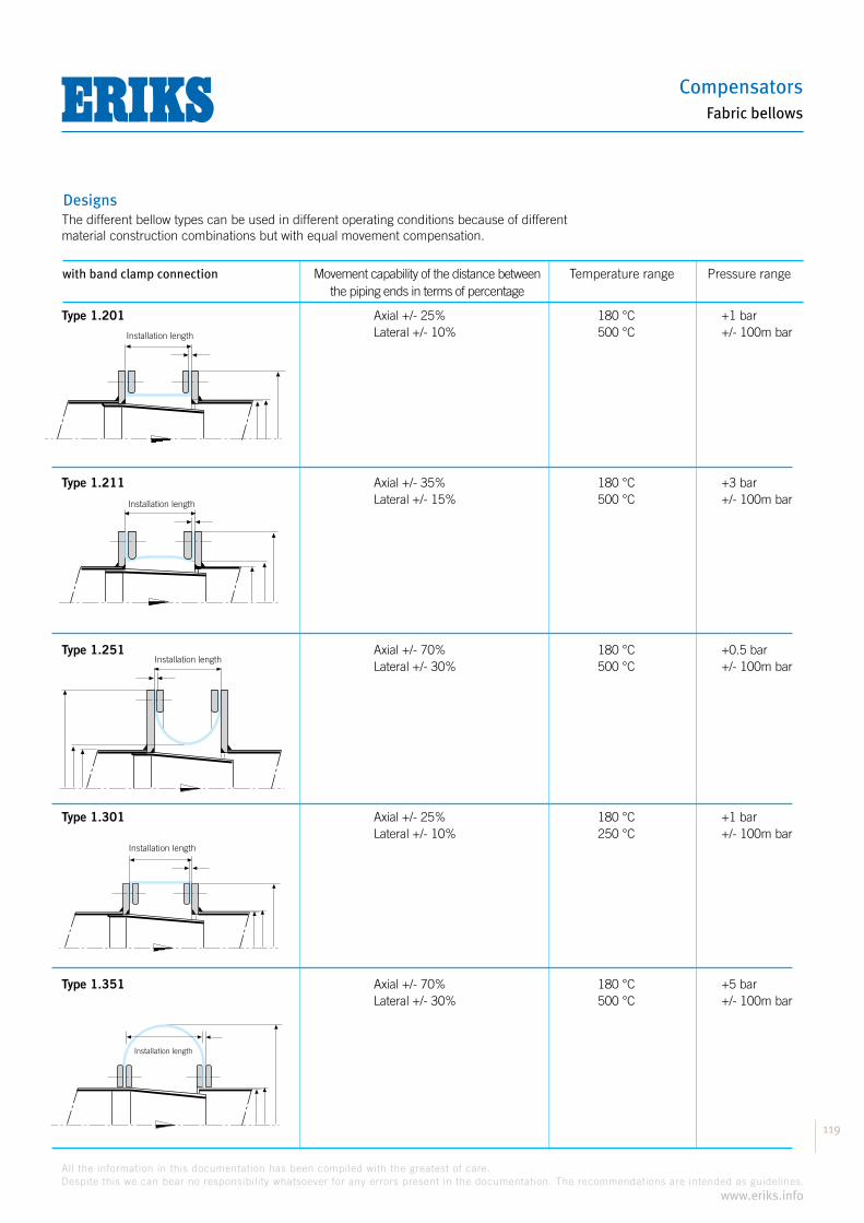
Compensators
119
All the information in this documentation has been compiled with the greatest of care.
Despite this we can bear no responsibility whatsoever for any errors present in the documentation. The recommendations are intended as guidelines.
www.eriks.info
Fabric bellows
DesignsThe different bellow types can be used in different operating conditions because of different material construction combinations but with equal movement compensation.
with band clamp connection Movement capability of the distance between the piping ends in terms of percentage
Temperature range Pressure range
Type 1.201 Axial +/- 25% 180 °C +1 bar Lateral +/- 10% 500 °C +/- 100m bar
Type 1.211 Axial +/- 35% 180 °C +3 bar Lateral +/- 15% 500 °C +/- 100m bar
Type 1.251 Axial +/- 70% 180 °C +0.5 bar Lateral +/- 30% 500 °C +/- 100m bar
Type 1.301 Axial +/- 25% 180 °C +1 bar Lateral +/- 10% 250 °C +/- 100m bar
Type 1.351 Axial +/- 70% 180 °C +5 bar Lateral +/- 30% 500 °C +/- 100m bar
Installatielengte
Installatielengte
Installatielengte
Installatielengte
Installatielengte
Installation length
Installation length
Installation length
Installation length
Installation length

Hoses and Accessories
120
All the information in this documentation has been compiled with the greatest of care.
Despite this we can bear no responsibility whatsoever for any errors present in the documentation. The recommendations are intended as guidelines.
www.eriks.info
Fabric bellows
DesignsThe different bellow types can be used in different operating conditions because of different material construction combinations but with equal movement compensation.
with band clamp connection Movement capability of the distance between the piping ends in terms of percentage
Temperature range Pressure range
Type 1.031/2 Axial +/- 70% 180 °C +1 bar Lateral +/- 30% 400 °C +/- 200m bar
Type 1.231/3 Axial +/- 60% 180 °C +1 bar Lateral +/- 30% 400 °C +/- 200m bar
Type 3.251 Axial +/- 70% 180 °C +0.5 bar Lateral +/- 20% 500 °C +/- 100m bar
Type 1.422 Axial +/- 100% 180 °C +3 bar Lateral +/- 10% 500 °C +/- 100m bar
Type 2.422 Axial +/- 70% 180 °C +3 bar Lateral +/- 10% 500 °C +/- 100m bar
Installatielengte
FF
Installatielengte
Installatielengte
Installatielengte
Installation length
Installation length
Installation length
Installation length

Compensators
121
All the information in this documentation has been compiled with the greatest of care.
Despite this we can bear no responsibility whatsoever for any errors present in the documentation. The recommendations are intended as guidelines.
www.eriks.info
Fabric bellows
DesignsThe different bellow types can be used in different operating conditions because of different material construction combinations but with equal movement compensation.
with band clamp connection Movement capability of the distance between the piping ends in terms of percentage
Temperature range Pressure range
Type 1.012 Axial +/- 80% 180 °C +1 bar Lateral +/- 20% 500 °C +/- 100m bar
Type 1.022 Axial +/- 50% 180 °C +1 bar Lateral +/- 20% 500 °C +/- 100m bar
Type 1.421 Axial +/- 30% 180 °C +1 bar Lateral +/- 10% 250 °C +/- 200m bar
Type 1.101 Axial +/- 25% 180 °C +1 bar Lateral +/- 10% 500 °C +/- 100m bar
Type 1.072 Axial +/- 80% 180 °C +0.5 bar Lateral +/- 20% 500 °C +/- 100m bar
Installatielengte
Installatielengte
FF
Installatielengte
Installatielengte
Installatielengte
Installation length
Installation length
Installation length
Installation length
Installation length
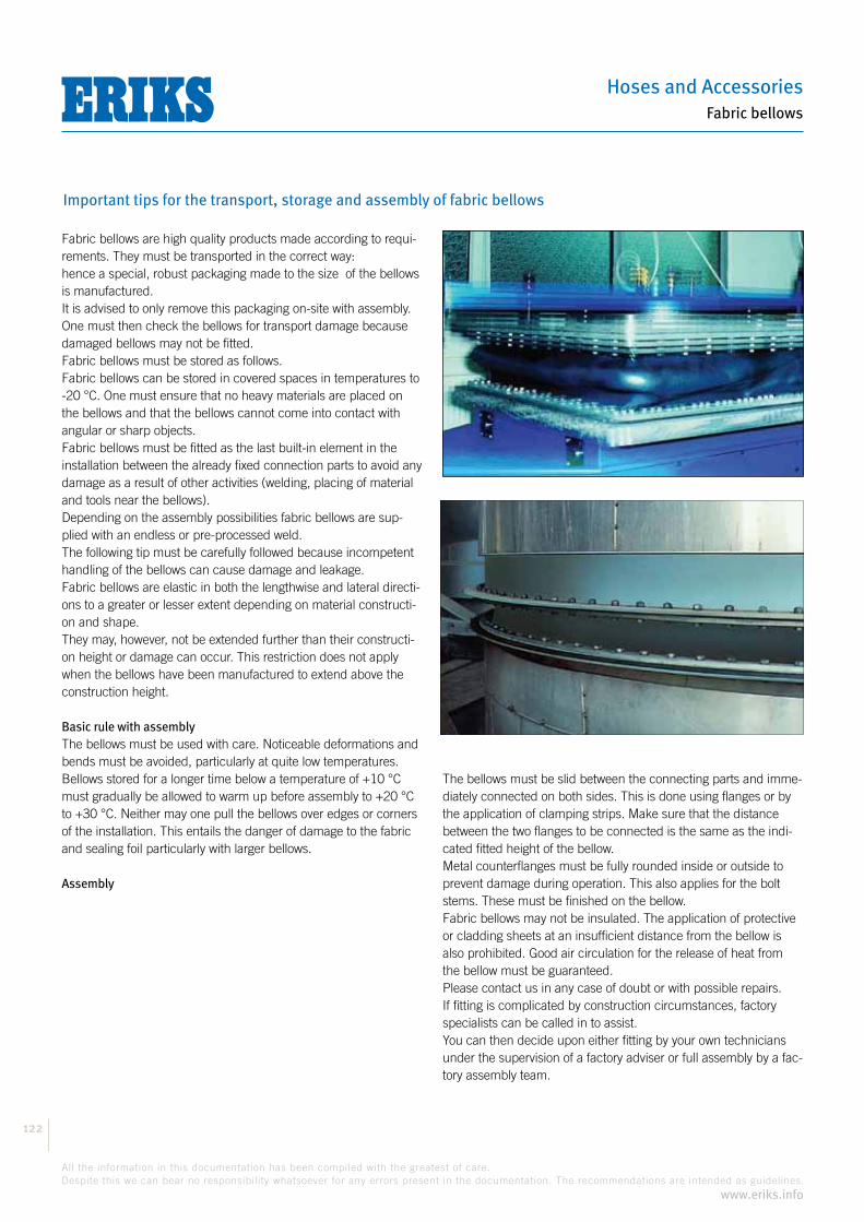
Hoses and Accessories
122
All the information in this documentation has been compiled with the greatest of care.
Despite this we can bear no responsibility whatsoever for any errors present in the documentation. The recommendations are intended as guidelines.
www.eriks.info
Fabric bellows
Important tips for the transport, storage and assembly of fabric bellows
Fabric bellows are high quality products made according to requi-rements. They must be transported in the correct way:hence a special, robust packaging made to the size of the bellows is manufactured.It is advised to only remove this packaging on-site with assembly.One must then check the bellows for transport damage because damaged bellows may not be fitted.Fabric bellows must be stored as follows.Fabric bellows can be stored in covered spaces in temperatures to -20 °C. One must ensure that no heavy materials are placed on the bellows and that the bellows cannot come into contact with angular or sharp objects.Fabric bellows must be fitted as the last built-in element in the installation between the already fixed connection parts to avoid any damage as a result of other activities (welding, placing of material and tools near the bellows).Depending on the assembly possibilities fabric bellows are sup-plied with an endless or pre-processed weld.The following tip must be carefully followed because incompetent handling of the bellows can cause damage and leakage.Fabric bellows are elastic in both the lengthwise and lateral directi-ons to a greater or lesser extent depending on material constructi-on and shape.They may, however, not be extended further than their constructi-on height or damage can occur. This restriction does not apply when the bellows have been manufactured to extend above the construction height.
Basic rule with assemblyThe bellows must be used with care. Noticeable deformations and bends must be avoided, particularly at quite low temperatures.Bellows stored for a longer time below a temperature of +10 °C must gradually be allowed to warm up before assembly to +20 °C to +30 °C. Neither may one pull the bellows over edges or corners of the installation. This entails the danger of damage to the fabric and sealing foil particularly with larger bellows.
Assembly
The bellows must be slid between the connecting parts and imme-diately connected on both sides. This is done using flanges or by the application of clamping strips. Make sure that the distance between the two flanges to be connected is the same as the indi-cated fitted height of the bellow.Metal counterflanges must be fully rounded inside or outside to prevent damage during operation. This also applies for the bolt stems. These must be finished on the bellow.Fabric bellows may not be insulated. The application of protective or cladding sheets at an insufficient distance from the bellow is also prohibited. Good air circulation for the release of heat from the bellow must be guaranteed.Please contact us in any case of doubt or with possible repairs.If fitting is complicated by construction circumstances, factory specialists can be called in to assist.You can then decide upon either fitting by your own technicians under the supervision of a factory adviser or full assembly by a fac-tory assembly team.

Compensators
123
All the information in this documentation has been compiled with the greatest of care.
Despite this we can bear no responsibility whatsoever for any errors present in the documentation. The recommendations are intended as guidelines.
www.eriks.info
Fabric bellows
Assembly of non-endless bellows
In many cases such as with bellows with insulation and gas flow guides or with spe-cial fitting situations, the bellow is supplied open or not-endless and the ends are only closed on assembly. The ends of the mate-rial layers have already been pre-pro-cessed for this.In these cases a good manual is supplied with which this can be simply made endless by your own technicians. In brief this comes down to the following:
Making an open bellow endless starts in the middle between 2 pre-processed ends. With assembly in horizontal piping one must make sure that the component seam is on top.
The joining of the layers commences by placing the innermost layers through the ends over each other and by gluing to each other. One can use adhesive with operating temperatures of 250 °C.At higher operating temperatures the innermost layers must be sewn to each other.
Special heat resistant thread is supplied for this. Only the last outer layer is then again glued.Suitable glue must be used depending on the impregnation of the outer layer.
Obviously the necessary care must be devoted to the fastening of the sealed bel-low to the pipe ends or flanges.
The closing of the seam starts with the innermost fabric layer.
The fabric is overlapped and glued.At temperatures above 250 °C this inner-most layer is sewn tight.
The second fabric layer is butt sealed.
The last fabric layer for the sealed foil is again overlapped and glued.
The closing of the sealed foil requires spe-cial care. Both ends are folded as close as possible to each other.
The long foil end is folded over the shorter end. Everything is then wound tight toge-ther and made flat.
Depending on the construction, after the sealing foil 1 or 2 layers of fabric material follow that are finally overlapped and glued.The assembled seam is glued and smeared on the outside with the same material as the material for outer impreg-nation (e.g. silicon rubber compound).

Hoses and Accessories
124
All the information in this documentation has been compiled with the greatest of care.
Despite this we can bear no responsibility whatsoever for any errors present in the documentation. The recommendations are intended as guidelines.
www.eriks.info
Fabric bellows
Question list for fabric bellows
When choosing fabric bellows it is important to know the operating conditions.A question list is included below to facilitate analysing the most important information.If you submit a completed copy of this list with your enquiry or order this will help in arriving at the right choice.
Company: ................................................................................ Contact person: ...............................................................................
Address: ................................................................................ ................................................................................ ............................
Telephone: ..................................................... Enquiry/projects: ................................................. Date: ...............................................
Required number of bellows: .......................................................................................................................................................
Operating conditions Normal Maximum
1. Temperature: Temperature of the medium ...........°C ...........°C Temperature in the bellow ...........°C ...........°C Temperature changes of ...........°C ...........°C Ambient temperature ...........°C ...........°C
2. Pressure: Overpressure during operation plus ............... mm Wk ........... mm Wk Underpressure during operation min ............... mm Wk ........... mm Wk Pressure changes from ....... to .......... mm Wk pulsed yes / no
3. Medium: Clean air yes / no moist ja / neen Dusty yes / no ........... g/m3
Grains coarse/fine ........... micron Solvent-containing yes / no Flue gases, sulphur-containing yes / no moist yes / no Soot content yes / no ........... g/m3
Chemical medium formula .......................................................................................................... Concentration in vol. % ..........................................................................................................
4. Humidity: Dew point underflow yes / no ........... times a day/month/year Spent gases acid yes / no Outside atmosphere dry/moist/tropical/chemical Setup inside building yes / no outside yes / no
5. Dimensions: Passage of the bellow ........... mm ...........°C Passage with built-on flange ........... mm ...........°C (mention accurate sizes of point 5 overleaf)
6. Design: With pre-processed shaft yes / no endless yes / no 7. Movements: Compression axial min ........... mm measured Elongation axial plus ........... mm from fitting Lateral movements ........... mm in assembly Angular movements ........... degrees state No. movements ........... times a day/month/year Vibrations yes / no frequency ........... Hz amplitude ........... mm
8. Insulation: Between bellow and guide yes / no ................ mm
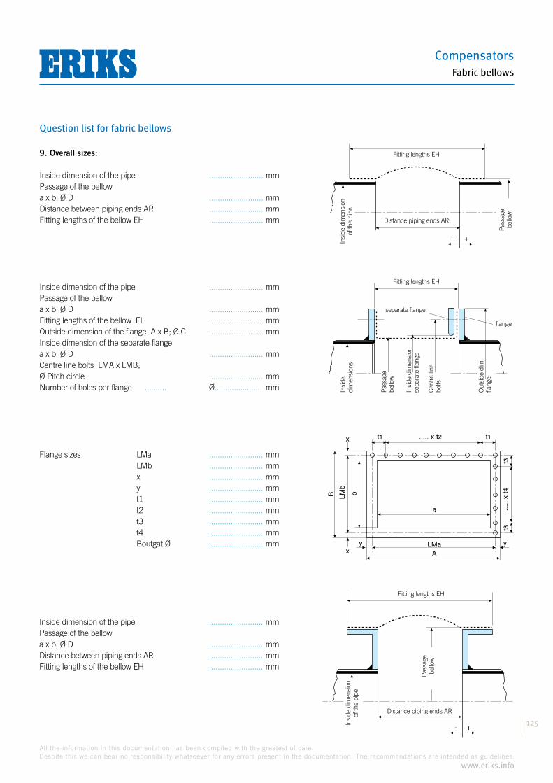
Compensators
125
All the information in this documentation has been compiled with the greatest of care.
Despite this we can bear no responsibility whatsoever for any errors present in the documentation. The recommendations are intended as guidelines.
www.eriks.info
Fabric bellows
Question list for fabric bellows
9. Overall sizes:
Inside dimension of the pipe ......................... mmPassage of the bellowa x b; Ø D ......................... mmDistance between piping ends AR ......................... mmFitting lengths of the bellow EH ......................... mm
Inside dimension of the pipe ......................... mmPassage of the bellowa x b; Ø D ......................... mmFitting lengths of the bellow EH ......................... mmOutside dimension of the flange A x B; Ø C ......................... mmInside dimension of the separate flangea x b; Ø D ......................... mmCentre line bolts LMA x LMB;Ø Pitch circle ......................... mmNumber of holes per flange .......... Ø...................... mm
Flange sizes LMa ......................... mm LMb ......................... mm x ......................... mm y ......................... mm t1 ......................... mm t2 ......................... mm t3 ......................... mm t4 ......................... mm Boutgat Ø ......................... mm
Inside dimension of the pipe ......................... mmPassage of the bellowa x b; Ø D ......................... mmDistance between piping ends AR ......................... mmFitting lengths of the bellow EH ......................... mm
leid
ing
binn
enm
aat
inbouwlengte EH
afstand
leidingeinden AR - + com
pens
ator
door
laat
leid
ing
binn
enm
aat
inbouwlengte EH
flens
buite
nmaa
t
losse flens
flens
com
pens
ator
door
laat
binn
enm
aat
loss
e fle
ns
hart
lijn
bout
en
a
t1t1 ..... x t2
t3t3
LMaA
bLMb
B
x
xy y
.....
x t4
leid
ing
binn
enm
aat
inbouwlengte EH
afstand
leidingeinden AR - +
com
pens
ator
door
laat
Fitting lengths EH
Fitting lengths EH
Fitting lengths EH
separate flange
flange
Distance piping ends AR
Insi
de d
imen
sion
of
the
pipe
Pas
sage
be
llow
Insi
de
dim
ensi
ons
Pas
sage
bello
w
Insi
de d
imen
sion
se
para
te fl
ange
Cen
tre li
ne
bolts
Out
side
dim
.fla
nge
Distance piping ends AR
Pas
sage
be
llow
Insi
de d
imen
sion
of
the
pipe

Hoses and AccessoriesBellows
126
All the information in this documentation has been compiled with the greatest of care.
Despite this we can bear no responsibility whatsoever for any errors present in the documentation. The recommendations are intended as guidelines.
www.eriks.info
NOTES

127
All the information in this documentation has been compiled with the greatest of care.
Despite this we can bear no responsibility whatsoever for any errors present in the documentation. The recommendations are intended as guidelines.
www.eriks.info
Hoses and AccessoriesBellows
NOTES

All the information in this documentation has been compiled with the greatest of care.
Despite this we can bear no responsibility whatsoever for any errors present in the documentation. The recommendations are intended as guidelines.
www.eriks.info
Hoses and AccessoriesBellows
128
NOTES