host adapter and software installation and user's...
TRANSCRIPT
60-0055-01 May 1998
8x4 Intelligent Multiport Host Adapter and
Software
Installation and User’s Guide

This equipment has been tested and found to comply with the limits for a Class A digital device, pursuant to Part 15 of the FCC Rules. These limits are designed to provide reasonable protection against harmful interference when the equipment is operated in a commercial environment. This equipment generates, uses, and can radiate radio frequency energy and, if not installed and used in accordance with the instruction manual, may cause harmful interference to radio communications. Operation of this equipment in a residential area is likely to cause interference in which case users will be required to correct the interference at their own expense.
Changes or modifications to this unit not expressly approved by Central Data could void the user’s authority to operate the equipment.
This digital apparatus does not exceed the Class A limits for radio noise emissions as set out by the ICES-003 standard, of the Canadian Department of Communications.
Cet apparell numérique n'émet pas de bruits radioélectriques depassant les limites de Classe A prescrites dans la norme NMB-003 édictée par le ministre des Communications du Canada.UNIX is a registered trademark of The Open Group in the USA and other countries. XENIX is a registered trademark of Microsoft Corporation in the United States and/or other countries. SCO is a trademark of The Santa Cruz Operation, Inc. in the USA and other countries. All other trademarks are the property of their respective owners.
ii
Copyright © 1987-1998 Central Data Corporation, All rights reserved.

Contents
How to Use This Manual..........................................1
1. Introduction...........................................................38x4 Intelligent Multiport Host Adapters...................................3Contacting Central Data...........................................................4Before Returning Your Product to Us......................................4
2. System Requirements..........................................5Supported Hardware.................................................................5Supported Operating System Variants......................................5Installation Overview................................................................6
3. Hardware Installation...........................................9Central Data Host Adapters......................................................9Central Data 8x4GT................................................................11EISA Configuration................................................................13
4. Software Installation for XENIX.........................15Installation Steps for XENIX..................................................15XENIX Terminal Naming Conventions.................................17Enabling Terminals Under XENIX........................................19Removing Software Under XENIX........................................19Known Problems....................................................................20
5. Software Installation for SVR3..........................21Installation Steps for UNIX SVR3.........................................21SVR3 Terminal Naming Conventions....................................23Enabling Terminals Under UNIX SVR3................................25Removing Software Under UNIX SVR3...............................25Alternate SVR3 Installation and Removal.............................25Known Problems....................................................................26
6. Software Installation for SVR4..........................27Installation Steps for SVR4....................................................27SVR4 Terminal Naming Conventions....................................29Enabling Terminals Under UNIX SVR4................................32
iii
Removing Software Under UNIX SVR4...............................32Known Problems....................................................................33
7. Configuring Serial Printers................................35
8. Configuring Transparent Printers.....................37Configuring Transparent Print Using the /etc/ttyprinter File. 37Configuring Transparent Print Using sprinter........................40
9. Configuring Multi-Screen...................................43Configuring Multi-Screen Using the /etc/ttyprinter File........43Configuring Multi-screen Using sprinter................................46
10. Support Software..............................................47mxd diagnostic........................................................................47sprinter....................................................................................47mxstty.....................................................................................47mxl..........................................................................................51mxrc........................................................................................52mxkern....................................................................................53mxcfg......................................................................................53Uninterruptable Power Supplies.............................................54
11. Hardware Specifications..................................55
12. Diagnostics.......................................................57Syntax.....................................................................................57Options....................................................................................57Test Descriptions....................................................................58Tech Test Commands.............................................................61
13. Troubleshooting...............................................63What to Check........................................................................63Error Messages.......................................................................65The “Host” Light Flashes Continuously.................................66A Terminal Is Not Working....................................................67Garbage Characters on the Screen..........................................67The Concentrator Does Not Stay On-line...............................67A Serial Printer Gives No Output...........................................68Serial Printer Prints Garbage Characters................................68Technical Support...................................................................69
iv
Appendix A. Demonstration Software..................71TTY Output Speed Benchmark..............................................71Recommended Procedure.......................................................72
Appendix B. File List..............................................73SVR3 & XENIX:....................................................................73UNIX SVR4:..........................................................................73
Index........................................................................75
v

How to Use This Manual
This manual details the installation and operation of the Central Data 8x4AT, 8x4GT, and 8x2AT host adapters and their associated device drivers and utility software.
The installation and operation of the 8-channel terminal concentrators (8/tcII or 8/tcfmII) is described in the 8/tcII and 8/tcfmII Terminal Concentrator Installation and User's Guide that comes with the concentrators (order number 60-0056-01).
Below is a description of the chapters of this manual.
1. Introduction – Overview of the product, plus information on how to contact us and what to do if you need to return the product to us for any reason.
2. System Requirements – Supported system hardware and operating systems, along with an overview of the installation process.
3. Hardware Installation – Installation of the host adapters in a system and details on switch settings.
4. Software Installation for XENIX® – Software installation details for XENIX operating system users.
5. Software Installation for SVR3 – Software installation details for UNIX SVR3 operating system users.
6. Software Installation for SVR4 – Software installation details for UNIX SVR4 operating system users.
7. Configuring Serial Printers – Using directly connected printers.
8. Configuring Transparent Printers – Configuring transparent printers attached to the auxiliary port of terminals.
9. Configuring Multi-Screen – Configuring secondary screens on terminals.
10. Support Software – Utility programs for the Central Data host adapters.
11. Hardware Specification – General hardware specifications for the host adapters.
12. Diagnostics – Descriptions of all diagnostic tests and their functions.
1

13. Troubleshooting – A brief guide to isolating problems.
A. Demonstration Software – How to run the demo programs.
B. File List – A list files included on the software distribution diskettes.
HighlightingThis manual uses the following highlighting conventions:
Bold Identifies commands, keywords, and file names.
Italics Identifies parameters whose actual value you supply.
2
1. Introduction
Central Data offers a full line of serial connectivity products for connecting terminals, printers, modems and other serial devices to a variety systems. This manual describes the Central Data 8x4 Intelligent Multiport host adapters.
The Central Data 8x4 Intelligent Multiport family includes a variety of mix-and-match intelligent host adapters and 8-port terminal concentrators (the 8/tcII and 8/tcfmII), which are the building blocks of Central Data's terminal concentrator architecture. The 8x4AT, 8x2AT, and 8x4GT are the current host adapter options. The most popular host adapter type is the 8x4AT, which will connect up to four terminal concentrators to a UNIX® system.
The Central Data 8x2AT host adapter is identical to the 8x4AT except that it can only connect to two terminal concentrators, and thus supports a maximum of 16 RS-232 devices. The Central Data 8x4GT is functionally very similar to the 8x4AT, but offers higher performance.
Throughout this manual, the term “8x4” refers to any of the three host adapters. Specific host adapters are referenced when needed.
8x4 Intelligent Multiport Host AdaptersUp to four 8x4 Intelligent Host Adapters can be installed within a host system. 8x4 host adapters connect to Central Data terminal concentrators, which offer a multiple-processor distributed architecture. This places intelligence both on the 8x4 host adapter and each remote 8-channel terminal concentrator unit. Different host adapter types can be intermixed within a host system, and the host adapters support intermixed terminal concentrator types.
Connections between the 8x4 host adapters and terminal concentrators are made through high speed RS-422 links. These host-to-concentrator connection cables can be as long as 1,000 feet (300 meters).
The 8x4AT and 8x2AT host adapters are half-length (the 8x4GT host adapter is full-length), and require a single slot in an ISA or EISA PC. The 8x2AT and 8x4AT host adapters feature 64K of dual-ported memory for data buffering and communication with the host processor (there is 128K on the 8x4GT), and they have an 80188 (80286 for the 8x4GT) processor. The host adapters send and receive data packets
Chapter 1: Introduction 3
between the on-board processor and the attached terminal concentrators. This off-loads some of the character processing overhead from the host processor. Each terminal concentrator has a Z80-type processor and 40K of memory to handle the lower level processing of terminal I/O. In a full 32-port host adapter/terminal concentrator configuration, five microprocessors share the serial I/O workload.
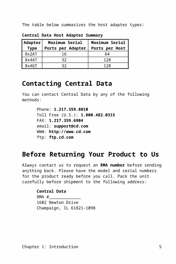
The table below summarizes the host adapter types:
Central Data Host Adapter SummaryAdapter
TypeMaximum Serial Ports
per AdapterMaximum Serial Ports per Host
8x2AT 16 648x4AT 32 1288x4GT 32 128
Contacting Central DataYou can contact Central Data by any of the following methods:
Phone: 1.217.359.8010Toll Free (U.S.): 1.800.482.0315FAX: 1.217.359.6904email: [email protected]: http://www.cd.comftp: ftp.cd.com
Before Returning Your Product to UsAlways contact us to request an RMA number before sending anything back. Please have the model and serial numbers for the product ready before you call. Pack the unit carefully before shipment to the following address:
Central DataRMA #_____________1602 Newton DriveChampaign, IL 61821-1098
4 Chapter 1: Introduction

2. System Requirements
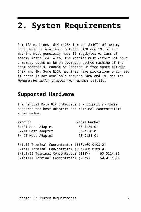
For ISA machines, 64K (128K for the 8x4GT) of memory space must be available between 640K and 1M, or the machine must generally have 15 megabytes or less of memory installed. Also, the machine must either not have a memory cache or be an approved cached machine if the host adapter(s) cannot be located in free space between 640K and 1M. Some EISA machines have provisions which aid if space is not available between 640K and 1M; see the Hardware Installation chapter for further details.
Supported HardwareThe Central Data 8x4 Intelligent Multiport software supports the host adapters and terminal concentrators shown below:
Product Model Number8x4AT Host Adapter 60-0125-018x2AT Host Adapter 60-0126-018x4GT Host Adapter 60-0124-01
8/tcII Terminal Concentrator (115V) 60-0108-018/tcII Terminal Concentrator (230V) 60-0109-018/tcfmII Terminal Concentrator (115V) 60-0114-018/tcfmII Terminal Concentrator (230V) 60-0115-01
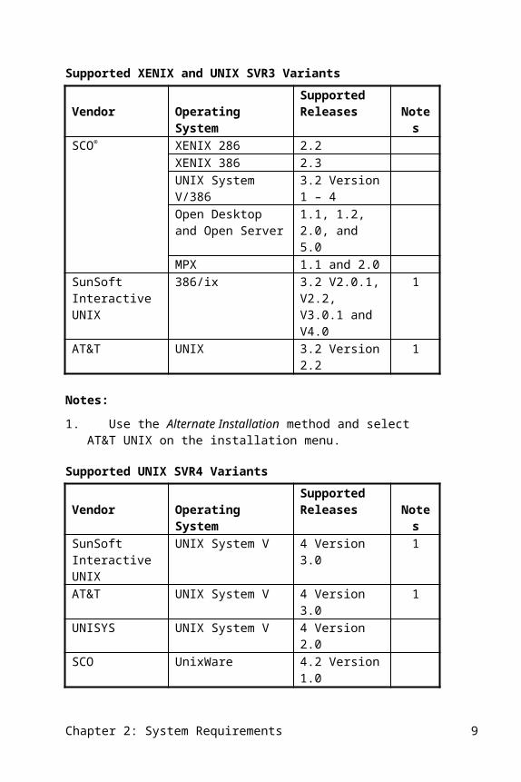
Supported Operating System VariantsCentral Data 8x4 multiport products are designed for use with the UNIX operating system which comes in several varieties. The next two tables show the UNIX variants by vendor and the associated release levels that Central Data supports based on your host UNIX environment (XENIX, UNIX SVR3, or UNIX SVR4). Note that Central Data products may operate in additional varieties that are compatible with one of those in the table but these are the variants that have been tested.
Chapter 2: System Requirements 5
Supported XENIX and UNIX SVR3 Variants
Vendor Operating SystemSupported Releases Notes
SCO® XENIX 286 2.2XENIX 386 2.3UNIX System V/386 3.2 Version 1 – 4Open Desktop and Open Server
1.1, 1.2, 2.0, and 5.0
MPX 1.1 and 2.0SunSoft Interactive UNIX
386/ix 3.2 V2.0.1, V2.2, V3.0.1 and V4.0
1
AT&T UNIX 3.2 Version 2.2 1
Notes:
1. Use the Alternate Installation method and select AT&T UNIX on the installation menu.
Supported UNIX SVR4 Variants
Vendor Operating SystemSupported Releases Notes
SunSoftInteractive UNIX
UNIX System V 4 Version 3.0 1
AT&T UNIX System V 4 Version 3.0 1UNISYS UNIX System V 4 Version 2.0SCO UnixWare 4.2 Version 1.0
Notes:
1. Select AT&T option when installing in this UNIX environment.
2. It has been Central Data's experience that all varieties of UNIX System V Release 4.0 Version 3.0 for the i386 have been very similar and will work by selecting the AT&T option during the installation.
Installation OverviewGenerally, other third party drivers can be installed either before or after the Central Data 8x4 Intelligent Multiport software is installed. However, some third party drivers may specify that they must be installed first or last. In that case, since Central Data’s software can be installed at any time, follow the directions of any such driver.
6 Chapter 2: System Requirements
The Central Data 8x4 Intelligent Multiport device driver is fully compatible with all UNIX commands, applications, and third party device drivers. Compatibility with add-in hardware is maximized since no hardware I/O address space is used.The following is an outline of the installation procedure. For actual step-by-step procedures, follow detailed instructions in the next four chapters.
There are two 3.5" floppy diskettes shipped with each host adapter. One is for the UNIX SVR3 (System V Release 3) and XENIX environments. The other is for UNIX SVR4 (System V Release 4, STREAMS). You will only use one of these, based on your host operating system environment.
1. Install the operating system, along with any required options as specified in the appropriate Software Installation chapter.
3. Install third-party I/O device drivers. (Third party drivers can be installed before or after the 8x4 Intelligent Multiport software installation.)
4. Install Central Data 8x4 Intelligent Multiport hardware. (Follow the directions in Hardware Installation chapter in this manual.)
5. Install Central Data 8x4 Intelligent Multiport software. (Follow the directions in the appropriate Software Installation chapter in this manual.)
6. Re-boot and run the system.
7. Enable ttys for login. Refer to the Terminal Naming Conventions section within the appropriate Software Installation chapter of this manual to understand which ttys to enable.
There are several chapters that detail software installation. The chapters differ based on your host operating system (XENIX, UNIX SVR3, or UNIX SVR4). Please refer to the chapter that applies to your host operating system environment.
Manual Configuration During Software InstallationDo not use the manual configuration during software installation for the 8x4GT board – this is known not to work properly.
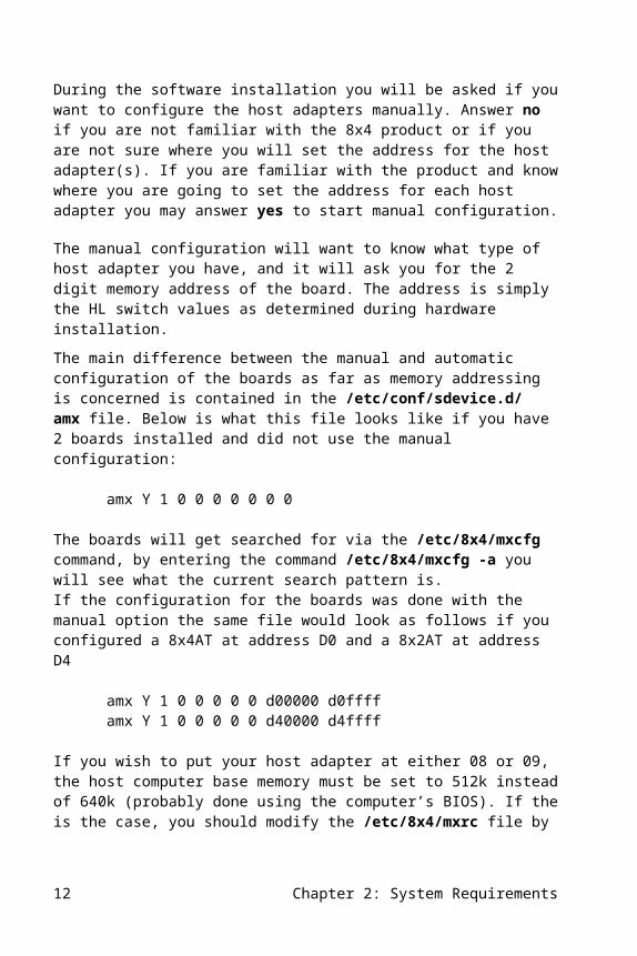
During the software installation you will be asked if you want to configure the host adapters manually. Answer no if you are not familiar with the 8x4 product or if you are not sure where you will set the address for the host adapter(s). If you are familiar with the product and know where you are going to set the address for each host adapter you may answer yes to start manual configuration.
Chapter 2: System Requirements 7
The manual configuration will want to know what type of host adapter you have, and it will ask you for the 2 digit memory address of the board. The address is simply the HL switch values as determined during hardware installation.
The main difference between the manual and automatic configuration of the boards as far as memory addressing is concerned is contained in the /etc/conf/sdevice.d/amx file. Below is what this file looks like if you have 2 boards installed and did not use the manual configuration:
amx Y 1 0 0 0 0 0 0 0
The boards will get searched for via the /etc/8x4/mxcfg command, by entering the command /etc/8x4/mxcfg -a you will see what the current search pattern is.If the configuration for the boards was done with the manual option the same file would look as follows if you configured a 8x4AT at address D0 and a 8x2AT at address D4
amx Y 1 0 0 0 0 0 d00000 d0ffffamx Y 1 0 0 0 0 0 d40000 d4ffff
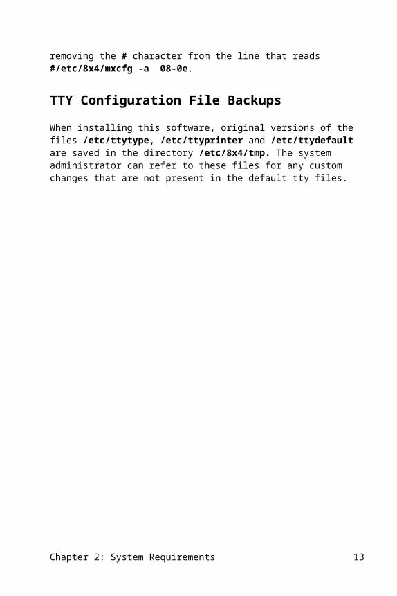
If you wish to put your host adapter at either 08 or 09, the host computer base memory must be set to 512k instead of 640k (probably done using the computer’s BIOS). If the is the case, you should modify the /etc/8x4/mxrc file by removing the # character from the line that reads #/etc/8x4/mxcfg -a 08-0e.
TTY Configuration File Backups When installing this software, original versions of the files /etc/ttytype, /etc/ttyprinter and /etc/ttydefault are saved in the directory /etc/8x4/tmp. The system administrator can refer to these files for any custom changes that are not present in the default tty files.
8 Chapter 2: System Requirements
3. Hardware Installation
The Central Data 8x4 Intelligent Multiport host adapters can be installed in any unused 16-bit (two connector) ISA or EISA slot on the motherboard.
Central Data Host AdaptersIf the system is operating, be sure to become the super user and give the haltsys or shutdown command (depending upon the operating system) before powering down the system.
WARNING: UNPLUG THE COMPUTER FROM THE AC POWER SOURCE BEFORE REMOVING THE COVER. FOLLOW THE COMPUTER MANUFACTURER’S INSTRUCTIONS CAREFULLY.
With the system powered down, remove the cover according to the manufacturer’s instructions for the computer. Then carefully plug one or more host adapters into 16-bit slots, and replace the system’s cover.
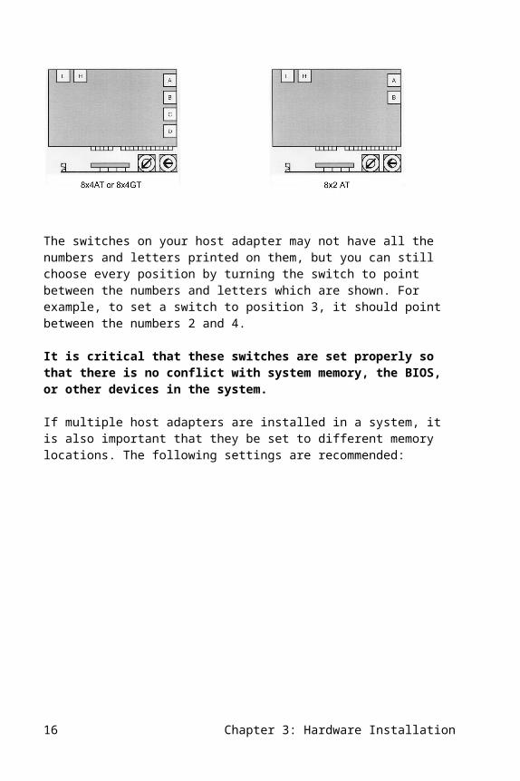
The 8x4AT and 8x4GT have four terminal concentrator channels, named A, B, C, and D. The 8x2AT has only two channels to terminal concentrators, named A and B.
There are two rotary switches on the host adapter labeled H and L. These switches define which AT bus memory addresses are used by the host adapter.
The switches on your host adapter may not have all the numbers and letters printed on them, but you can still choose every position by turning the switch to point
Chapter 3: Hardware Installation 9
between the numbers and letters which are shown. For example, to set a switch to position 3, it should point between the numbers 2 and 4.
It is critical that these switches are set properly so that there is no conflict with system memory, the BIOS, or other devices in the system.
If multiple host adapters are installed in a system, it is also important that they be set to different memory locations. The following settings are recommended:
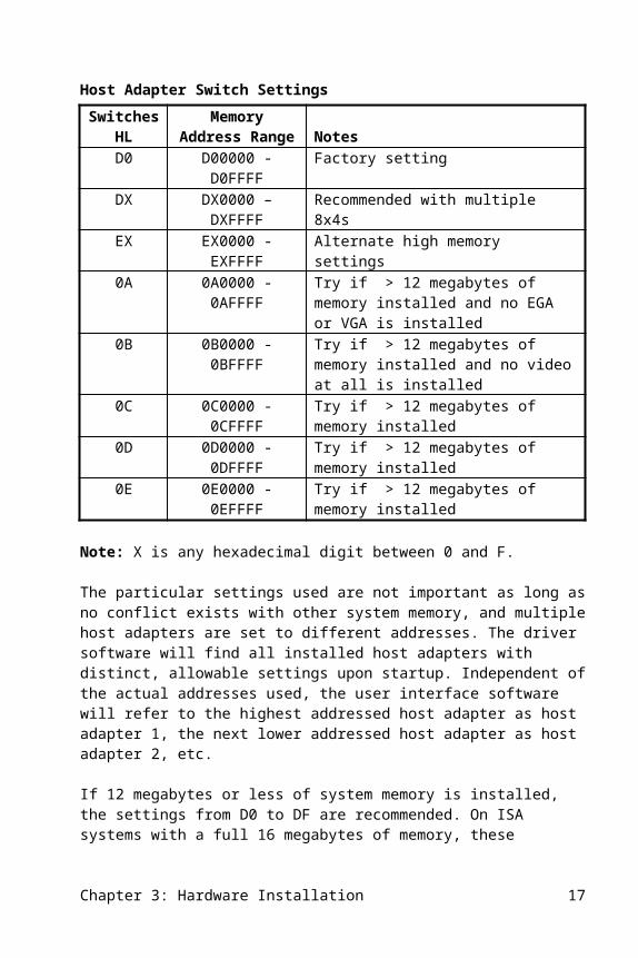
Host Adapter Switch SettingsSwitches
HLMemory Address
Range NotesD0 D00000 - D0FFFF Factory settingDX DX0000 – DXFFFF Recommended with multiple 8x4sEX EX0000 - EXFFFF Alternate high memory settings0A 0A0000 - 0AFFFF Try if > 12 megabytes of memory installed
and no EGA or VGA is installed0B 0B0000 - 0BFFFF Try if > 12 megabytes of memory installed
and no video at all is installed0C 0C0000 - 0CFFFF Try if > 12 megabytes of memory installed0D 0D0000 - 0DFFFF Try if > 12 megabytes of memory installed0E 0E0000 - 0EFFFF Try if > 12 megabytes of memory installed
Note: X is any hexadecimal digit between 0 and F.
The particular settings used are not important as long as no conflict exists with other system memory, and multiple host adapters are set to different addresses. The driver software will find all installed host adapters with distinct, allowable settings upon startup. Independent of the actual addresses used, the user interface software will refer to the highest addressed host adapter as host adapter 1, the next lower addressed host adapter as host adapter 2, etc.
If 12 megabytes or less of system memory is installed, the settings from D0 to DF are recommended. On ISA systems with a full 16 megabytes of memory, these addresses will be in conflict with RAM and therefore will not work properly. In that case, the area between 640K and 1M must be used instead. The settings 0A, 0B, 0C, 0D, and 0E are in that range. EISA systems can usually be configured with a memory "hole" using the EISA configuration utility, as described later in this chapter.
The “safest” setting among these is 0D, however the particular computer and the specific add-in cards installed will determine the potential conflicts for your system.
10 Chapter 3: Hardware Installation

Central Data 8x4GTDo not use the manual configuration during software installation for the 8x4GT board–this is known not to work properly.
The 8x4GT has 128K bytes of RAM whereas the 8x4AT and 8x2AT have only 64K. This larger RAM capability affects where the 8x4GT can be installed in the memory space of the host machine.
When installed above 1M (H switch not set to 0), the adapter will use 16-bit data transfers and will decode a 128K block of the address space. To install above 1M, that the H switch must not be set to 0 and that the L switch must be set to an even number. If the L switch is set to an odd number in this case, the host adapter will round down to the next lower number.
The 8x4GT can be installed below 1M in the host address space by setting the H switch to 0. In this case, the adapter will use 8-bit transfers and decode only 64K bytes of address space. The remaining 64K bytes are not accessible to the host but will be used by the 8x4GT. This will result in a slight performance degradation but will not otherwise affect the host adapter. When the H switch is 0, then all positions on the L switch are decoded, allowing the host adapter to be installed on a 64K boundary.
Systems With Over 16 MegabytesEven if your system has 16 or more megabytes of memory installed you may still be able to use these upper addresses for your host adapter. When your system has 16 or more megabytes of memory, there are two methods available to install the 8x4 in high memory:
1. If you are running an EISA system, you may be able to use the EISA configuration utility to force a gap in memory where the 8x4 may be installed. See EISA Configuration later in this chapter for a detailed explanation.
2. You may be able use a hardware feature called A31 cache control that is available on many motherboards, which permits an ISA card to share address space with motherboard memory. This method is available to SCO UNIX systems at release 3.2.4 or later only. The use of this feature is described below.
The A31 cache control mechanism is a hardware feature of the core logic on the motherboard that forces any processor memory reference with the A31 address bit set to the ISA bus such that the lower address bits map onto normal ISA bus
Chapter 3: Hardware Installation 11
addresses. Caching is disabled on these references to permit shared-memory adapters like the 8x4 family boards to operate properly.
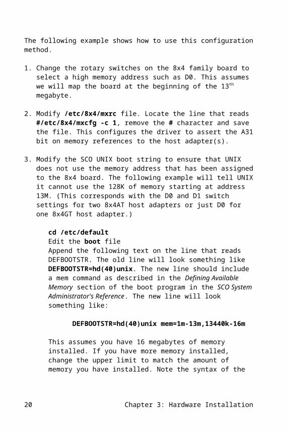
You can configure your 8x4 drivers to assert the A31 address bit on all memory references to the 8x4 board. The following example shows how to use this configuration method.
1. Change the rotary switches on the 8x4 family board to select a high memory address such as D0. This assumes we will map the board at the beginning of the 13th megabyte.
2. Modify /etc/8x4/mxrc file. Locate the line that reads #/etc/8x4/mxcfg -c 1, remove the # character and save the file. This configures the driver to assert the A31 bit on memory references to the host adapter(s).
3. Modify the SCO UNIX boot string to ensure that UNIX does not use the memory address that has been assigned to the 8x4 board. The following example will tell UNIX it cannot use the 128K of memory starting at address 13M. (This corresponds with the D0 and D1 switch settings for two 8x4AT host adapters or just D0 for one 8x4GT host adapter.)
cd /etc/defaultEdit the boot fileAppend the following text on the line that reads DEFBOOTSTR. The old line will look something like DEFBOOTSTR=hd(40)unix. The new line should include a mem command as described in the Defining Available Memory section of the boot program in the SCO System Administrator's Reference. The new line will look something like:
DEFBOOTSTR=hd(40)unix mem=1m-13m,13440k-16m
This assumes you have 16 megabytes of memory installed. If you have more memory installed, change the upper limit to match the amount of memory you have installed. Note the syntax of the mem command: no spaces are used anywhere, and commas are used to separate arguments.
The number 13440k is the next available address after the 128K gap reserved for the host adapter(s). (13440 = 1024 * 13 + 128)
CAUTION: Syntax problems in the boot file may prevent your system from booting properly (or at all), which would require you to boot from CD-ROM in order to recover your system. Be very careful when editing this file.
12 Chapter 3: Hardware Installation
4. Save the /etc/default/boot file and reboot the machine, the host adapter(s) should now be found upon startup and any terminal concentrators should come on-line.
5. If the board is still not found then the machine does not support the A31 feature. The 8x4 host adapter must then be installed in the low memory address range (between 640K - 1M).
EISA ConfigurationThe Central Data 8x4 Intelligent Multiport host adapter drivers include a copy of the !ISAC002.CFG file for configuring them into an EISA system. Fully compliant EISA systems include the ability to re-map memory, which permits the host adapter(s) to be installed in memory above 1 megabyte even when there are no gaps in physical memory. To use this feature, you will need to use this file in conjunction with the EISA Configuration utility.
For HP systems, use the file supplied by HP. If this is not available or does not work properly, use the file supplied with this software.
To add a Central Data host adapter to an EISA system, use the following steps:
1. Use doscp to copy the file /etc/8x4/!ISAC002.CFG onto the EISA Configuration Utility disk.
2. Boot DOS and run the EISA configuration utility.
3. Select Configure Computer from the list of options.
4. Choose the Advanced Method from the list of options from the configure window. The utility will now display a pictogram of the system bus.
5. Select the Edit option from the menu bar.
6. Choose the Add... option from the pop up window.
7. At this point the utility will present a list of all the .CFG files in the root directory of the installation drive. Select !ISAC002.CFG.
8. The utility will now prompt for the system bus slot to be used. Select an appropriate slot.
9. The Central Data host adapter will now appear in the system bus pictogram for the chosen slot and the highlight bar will be shown on the chosen slot also. Press Enter.
Chapter 3: Hardware Installation 13
10. The System Configuration Detail View screen will appear with the highlight bar on the Shared memory option for the Central Data host adapter. Press Enter.
11. The Change Function window will now appear with instructions for selecting a memory address for the particular Central Data host adapter. Select an appropriate memory address.
Note: This address and the address indicated on the host adapter's rotary switches must be identical.
At this point you may wish to select the View option from the menu bar, choose the Switch & Jumper Settings... option from the pop-up window, then select Show Settings for Current Host Adapter to verify the address selection.
12. Select the System option from the menu bar and choose the Exit option, when all the configuration information appears to be satisfactory.
13. Choose the Save Configuration and Exit option from the Exit window.
The utility will display a reminder to check the jumper settings and address selections and then to reboot the machine. This completes the installation of the Central Data host adapter in an EISA system.
Note: Not all EISA systems support this procedure. Systems from the following vendors are known to work: Compaq, HP, Digital, and Corollary.
14 Chapter 3: Hardware Installation
4. Software Installation for XENIX
This chapter provides step-by-step instructions for installing the Central Data 8x4 Intelligent Multiport software in systems running the XENIX operating system. Installation and removal of this software is facilitated by the custom program. If you are installing to systems running UNIX SVR3 or SVR4, please refer to the appropriate software installation chapter found later in this manual.
Installation Steps for XENIXTo install the Central Data 8x4 Intelligent Multiport software, perform the following steps:
1. Install the XENIX operating system following the directions given in the XENIX installation guide. The Run Time System (RTS) and the Basic Extended Utility Set (BASE) are required as a minimum.
2. Install the Link Kit (LINK) if it is not already installed.
3. Install any third party or other optional device drivers. Generally, other third party drivers can be installed either before or after the Central Data software is installed, but some may require that they be installed first or last.
4. If the system is in System Maintenance Mode, proceed with normal startup (press Control-D).
5. Log in as root or use the su command to become root.
6. Install the 8x4 Intelligent Multiport software with the custom command, which allows customized installation and removal of software packages.
The custom program is menu driven, and after appropriate user selections, builds and installs a new XENIX kernel, installs all support software, and creates required device nodes.
Chapter 4: Software Installation for XENIX 15
If this is the first time this product has been installed on the system, or if a previous installation has been completely removed, select Add a Supported Product at the first menu. Then the following message will be displayed: Insert distribution volume 1 and press <Return> or enter q to quit. Insert the Central Data UNIX SVR3 & XENIX software diskette and press Enter.
When the custom menu is displayed, select Install one or more Packages and you will see a menu which lists the installable Central Data software packages:
ALL Installs the drivers and the demo programs.
DRV Installs the 8x4 Intelligent Multiport driver and creates appropriate device nodes.
DEMO Installs a subdirectory called /mxdemo containing demo programs.
Normally ALL is selected, which loads all of the Central Data packages. The system will respond with Insert Central Data 8x4 Intelligent Multiport Software volume 1 and press <Return> or enter q to return to the menu. Press Enter. You will now be prompted for the following information:
Enter maximum number of 8x4 host adapters to be supported [1-4]:
Enter the appropriate number depending upon the number of host adapters you intend to use. Entering a number that is larger than you need will cause kernel data space to be used up unnecessarily, but will cause no problems. If needed, you can add more host adapters later and re-run custom to indicate the new number of host adapters you will be using. Next it will ask:
Do you wish to configure each host adapter manually [y/n]:
Do not use the manual configuration during software installation for the 8x4GT board – this is known not to work properly. If you answer n to this question the software will automatically establish tty naming conventions for the appropriate number of ports in your system based on the number of installed host adapters. Please note that this will create possible gaps in the tty names (see the next section entitled XENIX Terminal Naming Conventions for details). If you answer y to this question the software will eliminate the gaps in the naming conventions but you will be prompted for the following:
Host adapter x: Enter host adapter type [8x4gt 8x4 8x2 8x1]:Host adapter x: Enter host adapter 2 digit switch setting [00 - ff]:
Where x is the host adapter number associated with the host adapter you are configuring (from 1 to 4).
16 Chapter 4: Software Installation for XENIX
If you are installing the software on a XENIX 286 system you will be prompted for the following information since it only supports one host adapter:
Enter maximum number of channels to be supported [1-4]:
Each terminal concentrator provides eight tty ports. Enter the number of terminal concentrators you intend to use. Entering a number that is larger than you need will cause kernel data space to be used up unnecessarily but will not cause any problems. If you later add more terminal concentrators, you can re-run custom, and indicate the number of terminal concentrators you will be using.
Regardless of the type of system, the following information will be requested:
Beginning 8/tc letter [a-w, default a]:
The serial ports are referenced by a letter that corresponds to a terminal concentrator on a host adapter, and a number that identifies the port on the terminal concentrator (as described below). The initial terminal concentrator letter defaults to “a”. For each successive terminal concentrator, the system will automatically assign the next corresponding letter in the alphabet. The terminal concentrator’s ports are numbered from 1 to 8. For example, port 3 on the second terminal concentrator is normally known as /dev/ttyb3. This scheme may generate a name which conflicts with another device on the system. To avoid such a conflict, you may need to select a beginning letter other than “a”. Enter the lower case letter with which to begin; otherwise, press Enter. Refer to the next section and associated tables for terminal naming conventions for further information.
Depending upon the version of XENIX you are using, you will be asked a form of this question Do you wish to create a new kernel now? Press y. Next you will be asked Do you want this kernel to boot by default? Press y. This will copy the new kernel to /xenix. Finally, you will be asked Do you want to rebuild the kernel environment? Press y. When the installation is complete, give the haltsys command and reboot the default system. When the system boots, press Control-D to bring the system up in normal multi-user mode.
XENIX Terminal Naming ConventionsThe 8x4 Intelligent Multiport software for XENIX supports the following terminal naming convention:
/dev/ttyXY
Chapter 4: Software Installation for XENIX 17

where X specifies the terminal concentrator letter and Y specifies the port number on the host adapter. The valid XY options depend upon which host adapter is selected (i.e. 8x2 or 8x4) and the order in which the adapters are installed within the host system.
If you chose not to perform the manual host adapter configuration in the installation steps described in the previous section, the default values for the /dev/tty names are shown in the table below.
Default /dev/tty names for XENIXHost
Adapter ChannelNon-Modem Control
Modem Control
Transparent Print or Multi-Screen 8x2 8x4
1 A /dev/ttya[1-8] /dev/ttyA[1-8] /dev/ttya[1-8]p X XB /dev/ttyb[1-8] /dev/ttyB[1-8] /dev/ttyb[1-8]p X XC /dev/ttyc[1-8] /dev/ttyC[1-8] /dev/ttyc[1-8]p XD /dev/ttyd[1-8] /dev/ttyD[1-8] /dev/ttyd[1-8]p X
2 A /dev/ttye[1-8] /dev/ttyE[1-8] /dev/ttye[1-8]p X XB /dev/ttyf[1-8] /dev/ttyF[1-8] /dev/ttyf[1-8]p X XC /dev/ttyg[1-8] /dev/ttyG[1-8] /dev/ttyg[1-8]p XD /dev/ttyh[1-8] /dev/ttyH[1-8] /dev/ttyh[1-8]p X
3 A /dev/ttyi[1-8] /dev/ttyI[1-8] /dev/ttyi[1-8]p X XB /dev/ttyj[1-8] /dev/ttyJ[1-8] /dev/ttyj[1-8]p X XC /dev/ttyk[1-8] /dev/ttyK[1-8] /dev/ttyk[1-8]p XD /dev/ttyl[1-8] /dev/ttyL[1-8] /dev/ttyl[1-8]p X
4 A /dev/ttym[1-8] /dev/ttyM[1-8] /dev/ttym[1-8]p X XB /dev/ttyn[1-8] /dev/ttyN[1-8] /dev/ttyn[1-8]p X XC /dev/ttyo[1-8] /dev/ttyO[1-8] /dev/ttyo[1-8]p XD /dev/ttyq[1-8] /dev/ttyQ[1-8] /dev/ttyq[1-8]p X
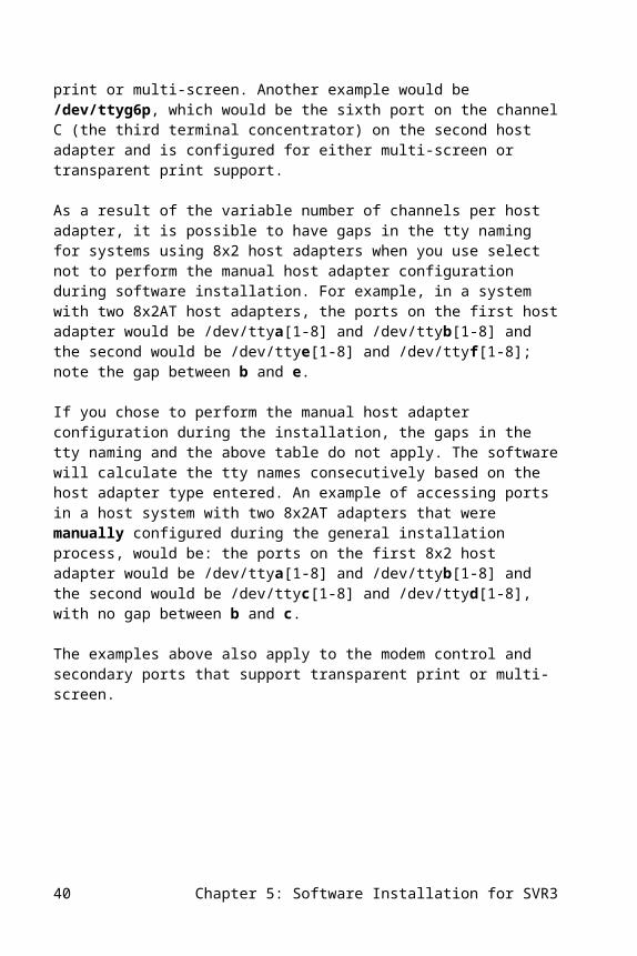
For example, /dev/ttym5 would access the fifth port on channel A (the first terminal concentrator) of the fourth host adapter and would be configured as a non-modem control port and without support for transparent print or multi-screen. Another example would be /dev/ttyg6p, which would be the sixth port on channel C (the third terminal concentrator) on the second host adapter, and is configured for either multi-screen or transparent print support.
As a result of the variable number of channels per host adapter, it is possible to have gaps in the tty naming for systems using 8x2 host adapters when you select not to perform the manual host adapter configuration during the software installation. For example, in a system with two 8x2AT host adapters, the ports on the first host adapter would be /dev/ttya[1-8] and /dev/ttyb[1-8] and the second would be /dev/ttye[1-8] and /dev/ttyf[1-8]; note the gap between b and e.
If you chose to perform the manual host adapter configuration during installation, the gaps in the tty naming and the above table do not apply. The software will calculate the tty names consecutively based on the host adapter type entered. An example of accessing ports in a host system with two 8x2 host adapters that were manually
18 Chapter 4: Software Installation for XENIX
configured during the software installation process, would be: the ports on the first 8x2 host adapter would be /dev/ttya[1-8] and /dev/ttyb[1-8] and the second would be /dev/ttyc[1-8] and /dev/ttyd[1-8], with no gap between b and c.
The examples above also apply to the modem control and the secondary ports that support transparent print or multi-screen.
Enabling Terminals Under XENIXTerminals can be activated for login by using the enable command. Terminals need to be enabled only once. Once a terminal is enabled, it will automatically get a login each time the system is re-booted.
Before enabling the terminal, change the gettydef reference in the /etc/ttys file to indicate the correct speed of the terminal. The name “0m” should be changed to “0n” for 19,200 baud terminals or “0o” for 38,400 baud terminals. To set baud rates higher than 38,400 bps, please refer to the mxstty command in the Support Software chapter of this manual.
When all ttys requiring logins are enabled, the installation of the software is complete and the system is ready for use. Access to the serial ports on the terminal concentrators is through devices in the /dev directory. Appendix A contains instructions on using the demo software that comes with the host adapters.
Removing Software Under XENIXTo remove all or part of the Central Data software, use the custom command. Select Central Data 8x4 Intelligent Multiport Software and then select Remove one or more packages.
Select ALL to remove all Central Data software, DEMO to remove the /mxdemo programs, or DRV to remove device nodes of all terminal concentrator related ttys.Even with ALL selected, custom will still list Central Data 8x4 Intelligent Multiport Software in its top-level menu. To remove Central Data software completely remove the /etc/perms/8x4 file. This will remove Central Data from the custom top level menu.
Chapter 4: Software Installation for XENIX 19
Known ProblemsIn addition to the following problem, refer to the Known Problems section of the Software Installation for SVR3 chapter for details on other possible issues with the XENIX driver.
CPR 1944 - 8x2 panics in XENIX systemProblem: A panic occurs on a 368 with 4 megabytes of memory under XENIX. The 8x2 card will sometimes panic. An 8x4 card installed in the same system works. This might be related to the small amount of ram installed in the 386.Workaround: None at this time.
20 Chapter 4: Software Installation for XENIX

5. Software Installation for SVR3
This chapter provides step-by-step instructions for installing the Central Data 8x4 Intelligent Multiport software on systems running the UNIX SVR3 operating system (such as SCO Open Desktop or Open Server). The custom program facilitates installation and removal of this software. If you are running the UNIX SVR4 or XENIX operating systems, please refer to the appropriate chapter in this manual for software installation.
Installation Steps for UNIX SVR3To install the Central Data 8x4 Intelligent Multiport software, perform the following steps:
1. Install a supported version of UNIX SVR3 following the directions given in your operating system installation guide. In addition to the Core System, the Kernel Configuration is a prerequisite.
2. Install any third party or other optional device drivers. Generally, other third party drivers can be installed either before or after the Central Data software is installed, but some may require that they be installed first or last.
3. If the system is in single user mode, proceed with normal startup (give the init 2 command).
4. Log in as root or use the su command to become root.
5. Central Data’s software is installed with the custom command, which allows easy installation and removal of software packages.
The custom program is menu driven, and after appropriate user selections, builds and installs a new SVR3 kernel, installs all support software, and creates required device nodes.
If this is the first time this product has been installed on the system, or if a previous installation has been completely removed, select Add a Supported Product at the first menu. Then the following message will be displayed: Insert distribution volume 1 and press <Return> or enter q to quit. Insert the Central Data UNIX
Chapter 5: Software Installation for SVR3 21
SVR3 & XENIX software diskette and press Enter. When the custom menu is displayed, select Install one or more Packages and you will see a menu which lists the installable Central Data software packages:
ALL Installs the drivers and the demo programs.
DRV Installs the 8x4 Intelligent Multiport driver and creates appropriate device nodes.
DEMO Installs a subdirectory called /mxdemo containing demo programs.
Normally ALL is selected, which loads all the Central Data packages. The system will respond Insert Central Data 8x4 Intelligent Multiport Software volume 1 and press <Return> or enter q to return to the menu. Press Enter. You will then be prompted for the following information:
Enter maximum number of 8x4 host adapters to be supported [1-4]:
Enter the appropriate number depending upon the number of host adapters you intend to use. Entering a number that is larger than you need will cause kernel data space to be used up unnecessarily, but will cause no problems. If you later add more host adapters, re-run custom and indicate the new number of host adapters you will be using. Next it will ask:
Do you wish to configure each host adapter manually [y/n]:
Do not use the manual configuration during software installation for the 8x4GT board – this is known not to work properly. If you answer n to this question the software will automatically establish tty naming conventions for the appropriate number of ports in your system based on the number of installed host adapters. Please note that this will create possible gaps in the naming conventions (see the next section entitled SVR3 Terminal Naming Conventions for details). If you answer y to this question the software will eliminate the gaps in the naming conventions but you will be prompted for the following:
Host adapter x: Enter host adapter type [8x4gt 8x4 8x2 8x1]:Host adapter x: Enter host adapter 2 digit switch setting [00 - ff]:
Where x is the host adapter number associated with the host adapter you are configuring (from 1 to 4). Next, the following information will be requested:
Beginning 8/tc letter [a-w, default a]:
The serial ports are referenced by a letter that corresponds to a terminal concentrator on the 8x4 and a number that identifies the port on the terminal concentrator (as described below). The initial terminal concentrator letter defaults to “a”. For each
22 Chapter 5: Software Installation for SVR3
additional terminal concentrator, the system will automatically assign the next corresponding letter in the alphabet. The terminal concentrator’s ports are numbered from 1 to 8. For example, port 3 on the second terminal concentrator is normally known as /dev/ttyb3. This scheme may generate a name that conflicts with another device. To avoid such a conflict, you may need to select a beginning letter other than “a”. Enter the lowercase letter with which to begin; otherwise, press Enter. Refer to the next section and associated tables for tty naming conventions for further information.
You will next be asked a form of this question: Do you wish to create a new kernel now? Press y. You will now be asked: Do you want to rebuild the kernel environment? Press y. When the installation is complete give the shutdown command and reboot the default system. When the system boots, use the init 2 command to bring the system up in multi-user mode.
SVR3 Terminal Naming ConventionsThe 8x4 Intelligent Multiport software for SVR3 uses the following tty naming convention:
/dev/ttyXY
where X specifies the terminal concentrator letter and Y specifies the port number on the terminal concentrator. The valid XY options depend upon which host adapter is selected (i.e. 8x2 or 8x4) and the order in which the host adapters are installed within the host system.
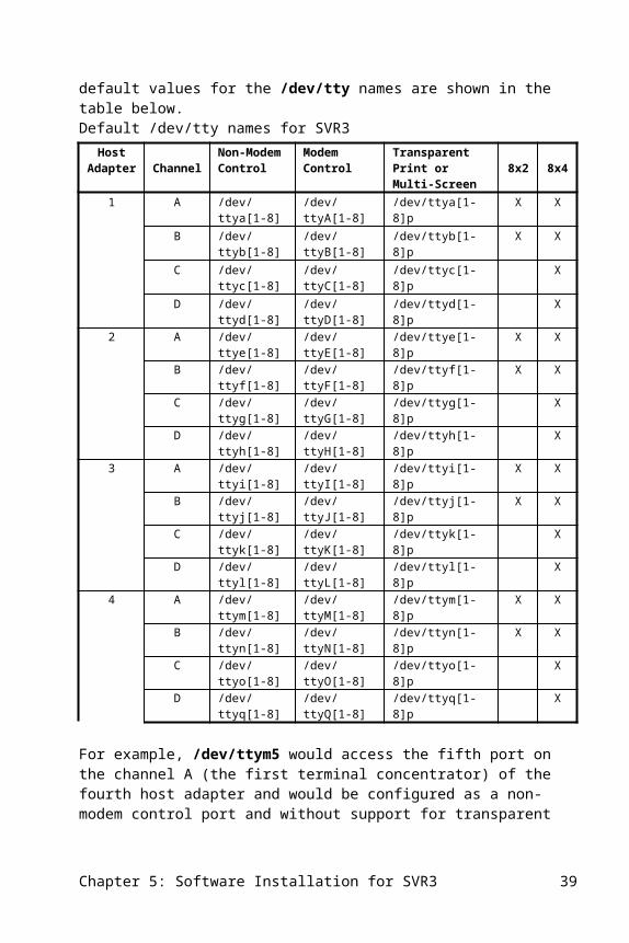
If you chose not to perform the manual host adapter configuration in the installation described earlier, the default values for the /dev/tty names are shown in the table below.
Chapter 5: Software Installation for SVR3 23

Default /dev/tty names for SVR3 Host
Adapter ChannelNon-Modem Control
Modem Control
Transparent Print or Multi-Screen 8x2 8x4
1 A /dev/ttya[1-8] /dev/ttyA[1-8] /dev/ttya[1-8]p X XB /dev/ttyb[1-8] /dev/ttyB[1-8] /dev/ttyb[1-8]p X XC /dev/ttyc[1-8] /dev/ttyC[1-8] /dev/ttyc[1-8]p XD /dev/ttyd[1-8] /dev/ttyD[1-8] /dev/ttyd[1-8]p X
2 A /dev/ttye[1-8] /dev/ttyE[1-8] /dev/ttye[1-8]p X XB /dev/ttyf[1-8] /dev/ttyF[1-8] /dev/ttyf[1-8]p X XC /dev/ttyg[1-8] /dev/ttyG[1-8] /dev/ttyg[1-8]p XD /dev/ttyh[1-8] /dev/ttyH[1-8] /dev/ttyh[1-8]p X
3 A /dev/ttyi[1-8] /dev/ttyI[1-8] /dev/ttyi[1-8]p X XB /dev/ttyj[1-8] /dev/ttyJ[1-8] /dev/ttyj[1-8]p X XC /dev/ttyk[1-8] /dev/ttyK[1-8] /dev/ttyk[1-8]p XD /dev/ttyl[1-8] /dev/ttyL[1-8] /dev/ttyl[1-8]p X
4 A /dev/ttym[1-8] /dev/ttyM[1-8] /dev/ttym[1-8]p X XB /dev/ttyn[1-8] /dev/ttyN[1-8] /dev/ttyn[1-8]p X XC /dev/ttyo[1-8] /dev/ttyO[1-8] /dev/ttyo[1-8]p XD /dev/ttyq[1-8] /dev/ttyQ[1-8] /dev/ttyq[1-8]p X
For example, /dev/ttym5 would access the fifth port on the channel A (the first terminal concentrator) of the fourth host adapter and would be configured as a non-modem control port and without support for transparent print or multi-screen. Another example would be /dev/ttyg6p, which would be the sixth port on the channel C (the third terminal concentrator) on the second host adapter and is configured for either multi-screen or transparent print support.
As a result of the variable number of channels per host adapter, it is possible to have gaps in the tty naming for systems using 8x2 host adapters when you use select not to perform the manual host adapter configuration during software installation. For example, in a system with two 8x2AT host adapters, the ports on the first host adapter would be /dev/ttya[1-8] and /dev/ttyb[1-8] and the second would be /dev/ttye[1-8] and /dev/ttyf[1-8]; note the gap between b and e.
If you chose to perform the manual host adapter configuration during the installation, the gaps in the tty naming and the above table do not apply. The software will calculate the tty names consecutively based on the host adapter type entered. An example of accessing ports in a host system with two 8x2AT adapters that were manually configured during the general installation process, would be: the ports on the first 8x2 host adapter would be /dev/ttya[1-8] and /dev/ttyb[1-8] and the second would be /dev/ttyc[1-8] and /dev/ttyd[1-8], with no gap between b and c.
The examples above also apply to the modem control and secondary ports that support transparent print or multi-screen.
24 Chapter 5: Software Installation for SVR3
Enabling Terminals Under UNIX SVR3Terminals can be activated for login using the system administration commands. Consult your operating system documentation for instructions on the use of the sysadm program. When all ttys requiring logins are enabled, the installation of the software is complete and the system is ready for use. Access to the serial ports on the terminal concentrators is through devices in the /dev directory. Appendix A contains instructions on using the demo software that comes with the host adapters.
Removing Software Under UNIX SVR3To remove all or part of the Central Data software, use the custom command. Select Central Data 8x4 Intelligent Multiport Software and then select Remove one or more packages.
Select ALL to remove all Central Data software, DEMO to remove the /mxdemo programs, or DRV to remove device nodes of all terminal concentrator related ttys.
Alternate SVR3 Installation and Removal The following steps are used as an alternative to using the custom program. This alternate installation can only be used on UNIX SVR3 systems. If the software is installed using this procedure, you must also remove it using this procedure; it will not appear in the custom menu for removal. Its absence from the custom menu should not cause alarm – the software will have been installed correctly if you follow this procedure.
cd /tar xvf /dev/diskette/etc/8x4/install
where diskette is the name of the device used to read high density diskettes. The sequence of commands is essentially the same as custom but has an additional menu to select operating system type.
Both the install and the remove command (below) should be run from single user mode as the root user.
Chapter 5: Software Installation for SVR3 25
To remove the Central Data software you can simply run the following commands:
cd //etc/8x4/remove
This will remove all Central Data 8x4 Intelligent Multiport software from the system. You will need to rebuild the kernel and reboot when prompted to eliminate the Intelligent Multiport driver from the kernel and finish the remove.
Known ProblemsCPR 1516 - 8x4GT not working after soft rebootProblem: After a soft boot the 8x4GT host adapter is not found or diagnostics fails on the board.Workaround: This problem has not been found to be very reproducible. If it happens, power off the host or press reset upon boot up.
CPR 2005 - Driver removal does not remove port entries from /etc/inittab in SCO 3.2v5.0.0Problem: After removing the product and rebuilding the kernel, the /etc/inittab file has the 8x4 port entries still defined. Workaround: After you remove the driver using custom, exit the custom utility and as root do the following:
rm /etc/inittabln -s var/opt/K/SCO/Unix/5.0.0Cl/etc/inittab /etc/inittab
If you have a problem you can always recover by rebuilding the kernel (/etc/conf/bin/link_unix) as this will re-create the /etc/inittab.
26 Chapter 5: Software Installation for SVR3
6. Software Installation for SVR4
This chapter provides step-by-step instructions for installing the Central Data 8x4 Intelligent Multiport software in systems running UNIX SVR4 operating systems. The pkgadd program is used for software installation. If you are running the UNIX SVR3 or XENIX operating systems, please refer to the appropriate chapter earlier in this manual for software installation.
Installation Steps for SVR4To install the Central Data 8x4 Intelligent Multiport software please perform the following steps:
1. Install a supported version of UNIX SVR4 following the directions given in your operating system installation guide. In addition to the Core System, the Kernel Configuration is a prerequisite.
2. Install any third party or other optional device drivers. Generally, other third party drivers can be installed either before or after the Central Data software is installed, but some may require that they be installed first or last.
3. If the system is in single user mode, proceed with normal startup (give the init 2 command).
4. Log in as root or use the su command to become root.
5. Central Data’s software is installed with the pkgadd -d diskette1 mxc command, which allows easy installation and removal of software packages.
This will load the software from the diskette and then ask a series of questions. For non-Unisys versions, you will be asked to reboot your system at the end of the installation. You should execute your normal shutdown and proceed with the reboot. The 8x4 Intelligent Multiport system will not begin operating until you reach multi-user mode after the reboot. The Unisys version is ready to use as soon as the installation completes.
During installation, you will be prompted for the following information:
Chapter 6: Software Installation for SVR4 27

Enter maximum number of 8x4 host adapters to be supported [1-4]:
Enter the appropriate number depending upon the number of host adapters you intend to use. Entering a number that is larger than you need will cause kernel data space to be used up unnecessarily, but will cause no problems. If you later add more host adapters, re-run pkgadd and indicate the new number of 8x4 host adapters you will be using. Next it will ask:
Do you wish to configure each host adapter manually [y/n]:
Do not use the manual configuration during software installation for the 8x4GT board – this is known not to work properly. If you answer n to this question the software will automatically establish tty naming conventions for the appropriate number of ports in your system based on the number of installed host adapters. Please note that this will create possible gaps in the naming conventions (see the next section entitled SVR4 Terminal Naming Conventions for details). If you answer y to this question the software will eliminate the gaps in the naming conventions but you will be prompted for the following:
Host adapter x: Enter host adapter type [8x4gt 8x4 8x2 8x1]:Host adapter x: Enter host adapter 2 digit switch setting [00 - ff]:
Where x is the host adapter number associated with the host adapter you are configuring (from 1 to 4).
Next, the following information will be requested:
Beginning 8/tc letter [a-w, default a]:
The serial ports are referenced by a letter that corresponds to a high-speed terminal concentrator channel on the 8x4 Intelligent Multiport adapter and a number that identifies the port on the terminal concentrator (as described below). Letters used for the serial port reference four consecutive letters. The initial letter defaults to the letter “a”. For each high-speed terminal concentrator channel, the system will automatically assign the next corresponding letter in the alphabet. The terminal concentrator’s ports are numbered from 1 to 8. For example, port 3 on the second terminal concentrator is normally known as /dev/ttyb3. This scheme may generate a name that conflicts with another device. To avoid such a conflict, you may need to select a beginning letter other than “a”. Enter the lowercase letter with which to begin; otherwise, press Enter. Please refer to the next section and associated tables for tty naming conventions.
You will be asked a form of the following question: Do you wish to create a new kernel now? Press y. You will then be asked: Do you want this kernel to boot by
28 Chapter 6: Software Installation for SVR4
default? Press y. This will copy the new kernel to /unix. Next you will be asked: Do you want to rebuild the kernel environment? Press y. When the installation is complete give the haltsys or shutdown command and reboot the default system. When the system boots, give the init 2 command to bring the system up in normal multi-user mode.
SVR4 Terminal Naming ConventionsThe 8x4 Intelligent Multiport software for SVR4 UNIX standard tty naming convention is as follows:
/dev/ttyXY
where X specifies the terminal concentrator letter and Y specifies the port number on the terminal concentrator. The valid XY options depend upon which host adapter is selected (i.e. 8x2 or 8x4) and the order in which the host adapters are installed within the system.
If you chose not to perform the manual host adapter configuration in the installation process described in the previous section, the default values for the /dev/tty names are shown in the table below.
Default /dev/tty names for SVR4Host
adapter ChannelNon-Modem Control
Modem Control
Transparent Print or Multi-Screen 8x2 8x4
1 A /dev/ttya[1-8] /dev/ttyA[1-8] /dev/ttya[1-8]p X XB /dev/ttyb[1-8] /dev/ttyB[1-8] /dev/ttyb[1-8]p X XC /dev/ttyc[1-8] /dev/ttyC[1-8] /dev/ttyc[1-8]p XD /dev/ttyd[1-8] /dev/ttyD[1-8] /dev/ttyd[1-8]p X
2 A /dev/ttye[1-8] /dev/ttyE[1-8] /dev/ttye[1-8]p X XB /dev/ttyf[1-8] /dev/ttyF[1-8] /dev/ttyf[1-8]p X XC /dev/ttyg[1-8] /dev/ttyG[1-8] /dev/ttyg[1-8]p XD /dev/ttyh[1-8] /dev/ttyH[1-8] /dev/ttyh[1-8]p X
3 A /dev/ttyi[1-8] /dev/ttyI[1-8] /dev/ttyi[1-8]p X XB /dev/ttyj[1-8] /dev/ttyJ[1-8] /dev/ttyj[1-8]p X XC /dev/ttyk[1-8] /dev/ttyK[1-8] /dev/ttyk[1-8]p XD /dev/ttyl[1-8] /dev/ttyL[1-8] /dev/ttyl[1-8]p X
4 A /dev/ttym[1-8] /dev/ttyM[1-8] /dev/ttym[1-8]p X XB /dev/ttyn[1-8] /dev/ttyN[1-8] /dev/ttyn[1-8]p X XC /dev/ttyo[1-8] /dev/ttyO[1-8] /dev/ttyo[1-8]p XD /dev/ttyq[1-8] /dev/ttyQ[1-8] /dev/ttyq[1-8]p X
In the table above, for example, /dev/ttym5 would access the fifth port on channel A (the first terminal concentrator) of the fourth host adapter and would be configured as a non-modem control port and without support for transparent print or multi-screen. Another example would be /dev/ttyg6p, which would be the sixth port on
Chapter 6: Software Installation for SVR4 29

channel C (the third terminal concentrator) on the second host adapter and is configured for either multi-screen or transparent printer support.
As a result of the variable number of channels per host adapter, it is possible to have gaps in the tty naming for systems using the host adapters when you use select not to perform the manual host adapter configuration during the installation process described in the previous section. For example, in a system with two 8x2AT host adapters the ports on the first host adapter would be /dev/ttya[1-8] and /dev/ttyb[1-8] and the second would be /dev/ttye[1-8] and /dev/ttyf[1-8]; note the gap between b and e.
If you chose to perform the manual host adapter configuration during the installation in the previous section, the gaps in the tty naming and the above table do not apply. The software will calculate the tty names consecutively based on the host adapter type entered. An example of accessing ports in a host system with two 8x2 Intelligent Multiport adapters that were manually configured during the general installation process, would be: the ports on the first 8x2 host adapter would be /dev/ttya[1-8] and /dev/ttyb[1-8] and the second would be /dev/ttyc[1-8] and /dev/ttyd[1-8], with no gap between b and c.
The examples above also apply to the modem control and secondary ports that support transparent print or multi-screen.
SVR4 Alternate Terminal Naming ConventionsAn alternate device naming style that applies only to the SVR4 environment is as follows:
/dev/term/XY
where the X specifies the terminal concentrator number and Y specifies the port number on the terminal concentrator. All other comments regarding terminal naming from above continue to apply.
30 Chapter 6: Software Installation for SVR4

Alternate /dev/term names for SVR4H.A. Chan.
Non-Modem Control
Modem Control Transparent Print or Multi-Screen 8x2 8x4
1 A /dev/term/2[0-7]n /dev/term/2[0-7] /dev/term/2[0-7]p X XB /dev/term/3[0-7]n /dev/term/3[0-7] /dev/term/3[0-7]p X XC /dev/term/4[0-7]n /dev/term/4[0-7] /dev/term/4[0-7]p XD /dev/term/5[0-7]n /dev/term/5[0-7] /dev/term/5[0-7]p X
2 A /dev/term/6[0-7]n /dev/term/6[0-7] /dev/term/6[0-7]p X XB /dev/term/7[0-7]n /dev/term/7[0-7] /dev/term/7[0-7]p X XC /dev/term/8[0-7]n /dev/term/8[0-7] /dev/term/8[0-7]p XD /dev/term/9[0-7]n /dev/term/9[0-7] /dev/term/9[0-7]p X
3 A /dev/term/10[1-8]n /dev/term/10[1-8] /dev/term/10[1-8]p X XB /dev/term/11[0-7]n /dev/term/11[0-7] /dev/term/11[0-7]p X XC /dev/term/12[0-7]n /dev/term/12[0-7] /dev/term/12[0-7]p XD /dev/term/13[0-7]n /dev/term/13[0-7] /dev/term/13[0-7]p X
4 A /dev/term/14[0-7]n /dev/term/14[0-7] /dev/term/14[0-7]p X XB /dev/term/15[0-7]n /dev/term/15[0-7] /dev/term/15[0-7]p X XC /dev/term/16[0-7]n /dev/term/16[0-7] /dev/term/16[0-7]p XD /dev/term/17[0-7]n /dev/term/17[0-7] /dev/term/17[0-7]p X
In the table above, for example, /dev/term/145 would access the sixth port on channel A (the first terminal concentrator) of the fourth host adapter and would be configured as a modem control port and without support for transparent print or multi-screen. Another example would be /dev/term/85p, which would be the sixth port on channel C (the third terminal concentrator) on the second host adapter and is configured for either multi-screen or transparent printer support or multi-screen.
As a result of the variable number of channels per host adapter, it is possible to have gaps in the tty naming for systems using the host adapters when you use select not to perform the manual host adapter configuration during the installation process described in the previous section. For example, in a system with two 8x2 host adapters the ports on the first host adapter would be /dev/term/2[0-7] and /dev/term/3[0-7] and the second would be /dev/term6[0-7] and /dev/term7[0-7]; note the gap between 3 and 6.
If you chose to perform the manual host adapter configuration during installation, the gaps in the tty naming and the above table do not apply. The software will calculate the tty names consecutively based on the host adapter type entered. An example of accessing ports in a host system with two 8x2 Intelligent Multiport adapters that were manually configured during the general installation process, the ports on the first 8x2 host adapter would be /dev/term/2[0-7] and /dev/term/3[0-7] and the second would be /dev/term4[0-7] and /dev/term5[0-7], with no gap between 3 and 4.
The example above also applies to the modem control and secondary ports that support transparent print or multi-screen.
Chapter 6: Software Installation for SVR4 31
Enabling Terminals Under UNIX SVR4Terminals can be activated for login using the mxenable command. The easiest way to enable a port is to use the Central Data supplied command mxenable. You should type mxenable ttyname speed where ttyname is the name of one of the tty devices you created during the installation. If you use the default, this will probably be something like /dev/ttya1. You can type the full path name or just the last portion as in "ttya1".
The parameter speed is the data rate you plan to use such as 38400. This parameter is optional. If you do not supply this parameter, mxenable will assume the value 9600. Note that this parameter actually selects one of the labels in the file /etc/ttydefs.
Note: Some /etc/ttydefs entries select both CS8 (8 bit data) and PARENB (parity enable). This combination is undefined and will not work with some terminal types. The entry should be either CS8 without PARENB or CS7 with PARENB.To disable a tty you can type mxdisable ttyname where ttyname is the name of a device you enabled with mxenable. Typing the mxenable command will create a tty port monitor with the name ttymonmx if it did not already exist.
Typing the mxdisable command will delete this tty port monitor when no more devices use it.
When all ttys requiring logins are enabled, the installation of the software for the concentrators is complete and the system is ready for use. Access to the serial ports on the terminal concentrators is through devices in the /dev directory. Appendix A contains instructions on using the demo software that comes with the host adapters.
Removing Software Under UNIX SVR4To remove all or part of the Central Data software, do the following:
Run mxdisable on all active ttys by typing the following:
mxdisable ttyxx
where xx is the tty number associated with the active ports on your system. Remove the 8x4 Intelligent Multiport software by typing:
pkgrm mxc
32 Chapter 6: Software Installation for SVR4
At this point all files associated with the 8x4 Intelligent Multiport software should be removed from your host system. Please note that your system will not recognize the removal of the 8x4 Intelligent Multiport software until you reboot your system.
Known ProblemsCPR 2006 - mxstty will not work with "trusted path"Problem: The mxstty command will not work in environments where a "trusted path" is used for tty devices.Workaround: The mxstty command can not be run before the "trusted path" is set up.
CPR 2007 - VPIX and DOS Merge Not SupportedProblem: Use of the DOS Merge package is not supported on 8x4 ports in this release. The 8x4 package will not interfere with its use on other ports in the system.Workaround: None at this time.
CPR 2008 - termiox Not SupportedProblem: Options to stty and IOCTLs associated with the termiox package are not supported in this release.Workaround: None at this time.
Chapter 6: Software Installation for SVR4 33

7. Configuring Serial Printers
Printers, terminals, and other RS-232 serial devices can be connected to the eight ports on the concentrator. If a printer is connected directly to a terminal concentrator, there are a few things to be noted.
For the 8/tcII, flow control is generally done using XON/XOFF protocol (software flow control). Most serial printers have the option of being placed in this mode. Hardware flow control can be used with the 8/tcII, if the port has been configured using the mxstty dcdflow command. In this case, the DCD input signal tells the 8/tcII when the printer is ready for data. The 8/tcfmII supports hardware flow control (using CTS/RTS) as well as XON/XOFF.
The SCO lpinit program provides a very easy way to configure a printer into your system. When prompted for the device name, give the device a name such as ttya1. This example uses the lower case “a” to cause the driver software to ignore the DCD signal for that port. This is important because most printers will drop CTS or DTR when taken off-line, when out of paper, etc. If the driver does not ignore DCD, it will abort the line printer spooler when DCD is no longer asserted.
The print spooler makes use of interface scripts that drive the output to printers. There are some things to note about the standard printer interface scripts provided with UNIX.
In order to prevent the end of print jobs from getting garbled characters, you should modify all printer interface scripts to include the line:
stty ixon 0<&1
just before the line that reads exit 0. This forces all pending output to be flushed to the printer before returning control to the printer spooler. If you are running an SCO operating system, you should use the command
/usr/spool/lp/bin/drain.output
instead of the stty ixon 0<&1 command if that command is available on your computer.
You should use the “serial device requiring <nl> to <cr><lf> mapping” interface for most “dumb” printers. If you are using SCO XENIX version 2.3, note that there is an
Chapter 7: Configuring Serial Printers 35
oversight in that interface script. After configuring a serial device with that interface, edit the interface file (/usr/spool/lp/interface/<printer name>) and change the line:
stty onlcr 0<&1
to:
stty ixon onlcr 0<&1
This will turn on XON/XOFF handshaking to the device (the default script leaves it off). The HP LaserJet interface script does not have this problem.
See your operating system documentation for more information regarding the setup of system printers and the spooling program provided with your operating system.
36 Chapter 7: Configuring Serial Printers
8. Configuring Transparent Printers
Printers can be attached to the auxiliary ports of terminals and then be used as general purpose system printers, independent of work being done on the associated terminal. Central Data has implemented this capability in a manner that is easy to use and offers improved reliability over alternate approaches used by some other serial port products.
There are two ways to configure transparent printing on a terminal's auxiliary port:
1. Make an entry in the /etc/ttyprinter file. This will enable transparent printing each time your system is rebooted, on the ports designated with transparent printer support.
2. Use the sprinter command on the terminal where you want transparent printer support. This will enable transparent printing until your system is rebooted, at which time your terminal will be reset to the default parameters.
Refer to the appropriate transparent printing section below for more details.
Configuring Transparent Print Using the /etc/ttyprinter FileThe /etc/ttyprinter file controls the operation of transparent printing. It is used to switch the character stream to a printer or to the terminal, indicate the average printing rate supported, and can also specify the terminal type.
The device name for the auxiliary port is the name of the non-modem version of the port (lowercase letter) with the letter “p” appended, an example is a printer attached to a terminal on port 2 of the terminal concentrator connected to the first channel (A) of the first host adapter has the name /dev/ttya2p.
The terminal type field provides information needed to avoid sending characters to the printer port in the middle of multi-character control sequences being sent to the terminal. A typical entry in this file might be:
Chapter 8: Configuring Transparent Printers 37
ttya2 escdef wy60 rate 120 enter ^X exit ^T
Where:
ttya2 The primary tty to which the transparent printer is connected. To access the transparent printer, use /dev/ttya2p, which is port of the terminal on port 2 of the first terminal concentrator.
escdef The terminal type. Supported terminal types include none, dumb, wy60 qvt101, and ansi. See the /etc/ttyprinter file for other currently supported terminal types. If no escape definition is specified, printing will still operate but certain terminal operations may inadvertently cause printer data to appear on the screen. More escdef information directly follows this table.
rate The number of characters per second that will be sent to the printer, not the baud rate to the printer. If the rate is set higher than the actual average number of characters per second throughput of the printer, the printer may send an XOFF command to the terminal, stopping the terminal’s use until the printer can accept more characters.
enter/exit The character string to be sent to the terminal that causes the terminal to enter or exit its “transparent copy” mode, respectively. Refer to the manual for the specific terminal to determine the correct sequence to enter and exit pass-through printing mode. Specifying a terminal type with the escdef parameter does not specify an enter or exit string. They must be specified with the enter and exit parameters.
Special characters may be specified in the enter and exit strings as follows:
\e Escape\n Newline\r Carriage return\\ Backslash\nnn Octal representation of character is the three-digit number nnn.^letter (caret symbol followed by a letter) is a control character.-f With the -f option, a file is used to set the parameters for one or more
terminals. If no file is provided, /etc/ttyprinter is used.
The terminal type is called escdef, which stands for escape definition. This feature is used to guarantee that no characters intended for the printer end up on the terminal’s screen inadvertently. By specifying an appropriate escdef for your terminal, the Central Data driver software will correctly determine the allowable times to switch between the terminal data traffic and the printer data traffic. This Central Data feature prevents multi-character cursor positioning or other control sequences from
38 Chapter 8: Configuring Transparent Printers
being interrupted by a command to switch output to the printer port. The escdef is used to determine when it is permissible to switch to the auxiliary port.
Escape sequences for some terminals are subsets of those of more powerful terminals; in this case, the escdef setting for the more powerful terminal can be used for both terminals. For example, the “wy60” escdef handles both the Wyse 60 and Wyse 50 terminals.
The escape definition “dumb” is correct for a wide range of ASCII terminals based on the ADM-3 escape sequences. If your terminal is not specifically supported at this time, use dumb (for most ASCII terminals) or ANSI (for ANSI or VT100 type terminals).
ansi A generic definition for terminals whose control sequences are of the form specified in ANSI 3.64, including the DEC VT100 and VT220, the Wyse 75, and many others. Due to the consistent form of ANSI 3.64 control sequences, this escape definition should be “complete” (that is, recognize all possible control sequences) for ANSI style terminals. One way to determine if a terminal is ansi is to check the escape sequence for cursor movement: ansi terminals will use an escape sequence of the form “<ESC>[<row>;<col>H”.
dumb A generic definition for most other ASCII terminals whose control sequences are similar to the ADM-3 or “dumb” terminal. Due to the wide variance in extensions made to the original “dumb” sequences, this is not a very complete definition, but it is complete enough that this definition should work fine for applications that use termcap. Applications “tuned” for a particular terminal that don’t use termcap may require a more specific terminal definition such as the ones below. The cursor movement escape sequence used by “dumb” terminals is either “<ESC>=<r><c>” or “<ESC>Y<r><c>” where <r> and <c> are single characters that denote the destination row and column.
wy60 Complete definition of escape sequences for the Wyse 60 terminal. Use this escdef for Wyse 50 terminals as well: the Wyse 50 escape sequences are a subset of the Wyse 60.
qvt101 Complete definition of escape sequences for the ITT/Qume model 101 terminal.
See the /etc/ttyprinter file for the currently supported terminals.
If your terminal does not appear on this list, it is probably supported by either the ansi or “dumb” escape definition; use the “transparent copy” or “transparent print” on and off sequences from the terminal’s user’s guide for the “enter” and “exit” parameters, respectively. In the table below, the escape character is shown as “^[“.
Chapter 8: Configuring Transparent Printers 39
Typical /etc/ttyprinter Entries for Transparent PrintTerminal escdef enter exit NotesVT100, VT200, VT220, VT300 ansi \e[5i \e[4iWyse 30 wy60 \030^X \024^TWyse 50 wy60 ^[d# ^T 1Wyse 60 wy60 ^[d# ^T 1Qume/ITT 101 qvt101 ^R ^T^[ATelevideo (TV910, 920, 924, 925, 950) dumb ^[‘ ^[a 2
Note 1: There are two ways to enter transparent print or multi-screen mode on Wyse terminals: either a single “^X” or the sequence “^[d#”. The first can be used only if the terminal is not in “Enhance” mode; the second is recommended. Please note that the pound sign character ‘#’ is used to set off comments in the /etc/ttyprinter file and therefore it must be escaped with a backslash. For example, an appropriate entry for a Wyse 50 or 60 terminal could be:
ttya1 escdef wy60 rate 120 enter \ed\# exit ^T Note 2: Note that the enter sequence is “escape back-quote” and not “escape single-quote” or “escape backslash”.
Configuring Transparent Print Using sprinterIf you do not want the auxiliary port on your terminal to be configured for transparent printer support each time you reboot your host system, then you should use the sprinter utility. The sprinter utility reconfigures the port on which you execute it until you reboot your system or reset the port, again using sprinter.For example:
sprinter escdef wy60 rate 120 enter ^X exit ^T
This sets the transparent print parameters for the terminal that this command is typed on: the escape definition is set to wy60, printing rate to 120 cps, the enter string set to Control-X, and the exit string set to Control-T. Although these enter and exit strings are single characters, multiple-character strings are also supported.
As another example:
sprinter rate 50
40 Chapter 8: Configuring Transparent Printers

would change the character/second rate on the auxiliary port of the terminal it was executed on to 50 cps. This changes only the printing rate; other parameters are unchanged.
The command:
sprinter
would cause the escdef, enter, exit, and rate parameter values for the printer port located on the terminal executing the command to be printed.
The best method of changing the characteristics of the printer ports for several terminals is to edit the /etc/ttyprinter file. It will be re-evaluated on the next system boot, or by using the command:
sprinter –f
to have that file re-evaluated while the system is still up.
Chapter 8: Configuring Transparent Printers 41
9. Configuring Multi-Screen
Terminals connected to a host system using Central Data's 8x4 Intelligent Multiport products can be configured to support multiple screens using the multi-screen feature. This allows a user to toggle between two screens on a single terminal with a single key stroke.
Like transparent printing, multi-screen uses the secondary virtual tty associated with a device, for example: /dev/ttya2p. The device name for the secondary virtual tty is the name of the primary device with the letter 'p' appended to the end. In addition, a terminal connected to a multi-screen device must support switching between multiple pages of memory for the screen to refresh properly.
There are two ways to configure multi-screen on a port:
1. Make an entry in the /etc/ttyprinter file. This will enable multi-screen each time your system is rebooted on the ports designated with multi-screen.
2. Use the sprinter command on the terminal you want multi-screen. This will enable multi-screen until your system is rebooted, at which time it will be reset to a standard port.
Please refer to the appropriate multi-screen section below for more details.
Configuring Multi-Screen Using the /etc/ttyprinter FileUsing a text editor, make the following entry in your /etc/ttyprinter file:
ttya1 escdef string screen1 string screen2 string hotkey1 string hotkey2 string
Where:
Chapter 9: Configuring Multi-Screen 43
ttya1 The primary tty which is to run multi-screen. To access the secondary screen, use /dev/ttya1p.
escdef The terminal type. Supported terminal types include none, dumb, wy60, qvt101, and ansi. See the /etc/ttyprinter file for other currently supported terminal types. More escdef information directly follows this table.
screen1/2 The control sequence that is used to make the terminal switch to a particular display page.
hotkey1/2 The control sequence that the user types to indicate that they desire to switch to a particular display page. This is typically the escape sequence generated by a function key. Please refer to the table later in this chapter for examples.
The above strings are best determined from the terminal manufacturer’s documentation.
The terminal type is called escdef, which stands for escape definition. This feature is used to guarantee that no characters intended for the secondary screen (multi-screen) end up on the primary terminal’s screen incorrectly. By specifying an appropriate escdef for your terminal, the Central Data driver software will correctly determine the allowable times to switch between the primary terminal data traffic and the secondary terminal's data traffic. This Central Data feature prevents multi-character cursor positioning or other control sequences from being interrupted by a command to switch output to the secondary screen. The escdef is used to determine when it is permissible to switch to the that screen.
If the terminal does not support multiple screen pages you can still use the multi-screen function, except that the screen will not refresh when you switch screens. To avoid confusion, use the terminal's clears screen escape sequence in place of the screen1 and screen2 strings.
Escape sequences for some terminals are subsets of those of more powerful terminals; in this case, the escdef setting for the more powerful terminal can be used for both terminals. For example, the “wy60” escdef handles both the Wyse 60 and Wyse 50 terminals.
The escape definition “dumb” is correct for a wide range of ASCII terminals based on the ADM-3 escape sequences. If your terminal is not specifically supported at this time, use dumb (for most ASCII terminals) or ANSI (for ANSI or VT100 type terminals).
An example for enabling multi-screen on a Wyse 60 terminal would be:
44 Chapter 9: Configuring Multi-Screen

ttya1 escdef wy60 screen1 \ew0 screen2 \ew1 hotkey1 ^A'\r hotkey2 ^Aa\r
Chapter 9: Configuring Multi-Screen 45
More information regarding escdef for the Wyse 60 (and other terminals) can be found below:
ansi A generic definition for terminals whose control sequences are of the form specified in ANSI 3.64, including the DEC VT100 and VT220, the Wyse 75, and many others. Due to the consistent form of ANSI 3.64 control sequences, this escape definition should be “complete” (that is, recognize all possible control sequences) for ANSI style terminals. One way to determine if a terminal is ansi is to check the escape sequence for cursor movement: ansi terminals will use an escape sequence of the form “<ESC>[<row>;<col>H”.
dumb A generic definition for most other ASCII terminals whose control sequences are similar to the ADM-3 or “dumb” terminal. Due to the wide variance in extensions made to the original “dumb” sequences, this is not a very complete definition, but it is complete enough that this definition should work fine for applications that use termcap. Applications “tuned” for a particular terminal that don’t use termcap may require a more specific terminal definition such as the ones below. The cursor movement escape sequence used by “dumb” terminals is either “<ESC>=<r><c>” or “<ESC>Y<r><c>” where <r> and <c> are single characters that denote the destination row and column.
wy60 Complete definition of escape sequences for the Wyse 60 terminal. Use this escdef for Wyse 50 terminals as well: the Wyse 50 escape sequences are a subset of the Wyse 60.
qvt101 Complete definition of escape sequences for the ITT/Qume model 101 terminal.
See the /etc/ttyprinter file for the currently supported terminals.
If your terminal does not appear on this list, it is probably supported by the “dumb” escape definition. In the table below, the escape character is shown as “^[“.Typical /etc/ttyprinter Entries for Multi-ScreenTerminal escdef screen1 screen2 hotkey1 hotkey2Wyse 30 wy60 ^[+ ^[+ ^A'\r ^Aa\rWyse 50 wy60 ^[w0 ^[w1 ^A'\r ^Aa\rWyse 60 wy60 ^[w0 ^[w1 ^A'\r ^Aa\rQume/ITT 101 qvt101 ^[J ^[K ^A@\r ^AA\rTelevideo (TV910, 920, 924, 925, 950)
dumb ^[J ^[K ^A@\r ^AA\r
46 Chapter 9: Configuring Multi-Screen
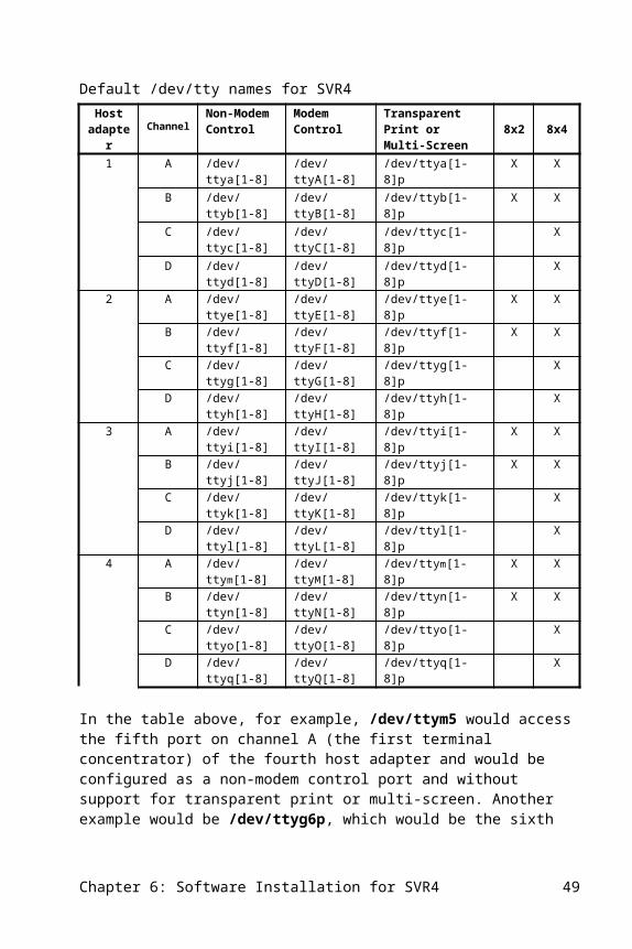
Note: hotkey1 is F1 and hotkey2 is F2 on the keyboards listed above.
Configuring Multi-screen Using sprinterIf you do not want your terminal to be configured for multi-screen each time the host system is booted, the sprinter command should be used. It reconfigures the port on which you perform the sprinter command for multi-screen until you reboot your system or use sprinter to remove support for multi-screen.
Usage:
sprinter escdef string screen1 string screen2 string hotkey1 string hotkey2 string
Where escdef, screen1, screen2, hotkey1 and hotkey2 are as described in the tables above associated with configuring multi-screen using the /etc/ttyprinter file. An example for configuring a Wyse 60 for multi-screen directly on your terminal type:
sprinter escdef wy60 screen1 \ew0 screen2 \ew1 hotkey1 ^A'\r hotkey2 ^Aa\r
The best method of changing the characteristics for multi-screen on several terminals is to edit the /etc/ttyprinter file. This file is re-evaluated on the next system boot, or you can give the following command to have that file re-evaluated while the system is still up:
sprinter -f
Chapter 9: Configuring Multi-Screen 47
10. Support Software
Central Data supplies utility programs to control the 8x4 Intelligent Multiport host adapters. They are described in this chapter.
mxd diagnosticThe 8x4 mxd program is a modular diagnostic consisting of over 50 tests and is executed as a utility program. See the Diagnostics chapter in this manual for details on the use of the diagnostic software.
sprinterThe sprinter program can be used much like the standard stty program. It is used to set the parameters for reliable transparent printing through the auxiliary port of a terminal or to configure multi-screen for a terminal. Refer to the Configuring Transparent Printers or Configuring Multi-Screen chapters within this manual for further details.
mxsttyThe mxstty program provides mechanisms for overriding some of the standard UNIX default processing for serial ports and their associated transparent print devices. This is sometimes useful with third-party software packages or add-on devices. Note that these features are only available with ports on Central Data terminal concentrators: mxstty does not work with other serial ports in your system. msxtty is used to enhance the default line conditioning at the time the port is opened.
One use of mxstty is to make XON/XOFF handshaking permanently enabled, regardless of the state of the “ixon” tty control bit. This is may be needed when using a device that requires XON/XOFF handshaking with an application that never sets the IXON bit or that changes the “ixon” bit during operation (such as FoxBase). Note that with XON/XOFF locked on, the XON (^Q) and XOFF (^S) characters will be intercepted by the driver and will never be passed to the application being used.Another use of mxstty is to change the parameters that are given to a port when it is first opened. This is needed when using an application that opens a port directly
Chapter 10: Support Software 49
(such as for printing) and does not set the port parameters. Finally, mxstty can be used to report information about a port.
The mxstty command is invoked in one of the following ways:
mxstty
This reports the mxstty settings for the terminal on which the command is run. To get the status of a another port, redirect standard input:
mxstty </dev/ttya1
to find out what the mxstty settings are for /dev/ttya1.
The following keywords are displayed to indicate the state of the tty port. Each may be preceeded by a "-" to indicate the state does not exist. The port state and defaults are displayed when mxstty is executed with no parameters or "-a" only.
modem This tty will generate SIGHUP on carrier loss (for the upper-case-letter tty name).
printer This is a pass-through print tty device.
mscreen This is a multi-screen device.
lockixon Lock the state of ixon to the enabled state so it cannot be disabled by stty or programs. After mxstty lockixon is executed, XON/XOFF flow control on output will always be in effect; after mxstty -lockixon, XON/XOFF flow control is determined by the “ixon” stty mode. The lockixon and -lockixon parameters can be mixed with the stty parameters above.
rtsflow Enable RTS for use as receive flow control. The RTS signal will drop when input buffers are full and be asserted when input can be received again. (rtsflow with ctsflow is the same as crtsfl under stty for SCO).
ctsflow Enable CTS for use as transmit flow control. (Same as ctsflow under stty for SCO UNIX/XENIX).
dcdflow Enable DCD for use as transmit flow control. (8/tcII only)
dcdtmo Enable DCD timer. If DCD is not asserted within 30 seconds from the time DSR is asserted, DTR will be dropped for 2 seconds.
lockioctl Lock the state of iflags and cflags so it cannot be disabled by stty or programs. After mxstty lockioctl is executed, the current values of iflag and cflag will always be in effect; after mxstty -lockioctl, users can change iflag and cflag values using mxstty.
50 Chapter 10: Support Software
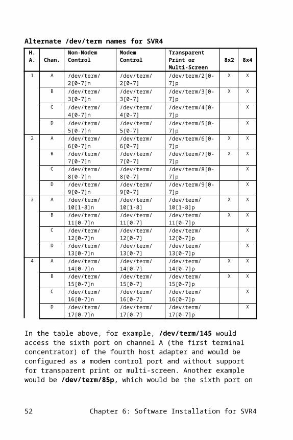
hibaud Enable a port to run baud rates above 38400. When the hibaud flag is set, the following baud rates will be mapped to support a higher throughput: The baud rate 2400 will yield 57600 when hibaud is set. The baud rate 4800 will yield 76800 when hibaud is set. The baud rate 19200 will yield 115200 when hibaud is set.
The following are stty port states. Adding a "-" prefix will disable the state.
ttstop The tty output has been stopped by software flow control.
ttblock The tty input has been stopped by software flow control.
rtsblock The tty input has been stopped by hardware flow control.
dcd The current state of the DCD modem control signal.
dsr The current state of the DSR modem control signal.
Other mxstty commands:
-a Show all stty modes when displaying default modes.
reset Disable default override. The stty modes on open will be determined by the operating system.
dtr Activate the DTR modem control signal (MXCIOCDTR ioctl). Deactivate DTR with -dtr.
rts Activate the RTS modem control signal (MXCIOCRTS ioctl). Deactivate RTS with -rts.
flush Flush tty input and output data buffers (TCFLSH ioctl).
break Generate a break condition on transmit (TSBRK ioctl).
hangup Drop DTR for 2 seconds.
resume Restart output if blocked by software flow control.
suspend Stop output until resumed by software flow control (same as -resume).
block Cause an XOFF character to be transmitted.
unblock Cause an XON character to be transmitted (same as -block).
-f This command causes the /etc/ttydefault file to be read to set the mxstty parameters for a number of ports. This command is automatically invoked when the system goes to multi-user mode, so that making an entry in /etc/ttydefault is a convenient way of causing a port’s settings to be changed whenever the system is booted.
Chapter 10: Support Software 51
Each entry in /etc/ttydefault consists of a single port containing the simple tty name of the port to be set (such as “ttya4”) followed by the default port parameters desired (“lockixon” and/or any stty modes). Lines starting with a ‘#’ in /etc/ttydefault are comments. See the /etc/ttydefault file for further examples.
mxstty <stty-parameters>
This sets the parameters used when the port associated with “standard input” is opened. As above, standard input can be redirected to any concentrator port. <stty-parameters> can be any parameters that can be set with the stty command (see the UNIX manual page for information). For example,
mxstty 19200 ixon onlcr < /dev/ttya2
sets up /dev/ttya2 so that when it is opened, it will be set to 19200 baud with XON/XOFF control enabled and with newlines on output converted to CR/LF sequences. Note that these parameters are in effect only when the port being opened was completely closed (that is, not opened by any other process on the system). Changing the defaults will not change the tty modes when the port is reopened by forking another process.
The 8/tcII and 8/tcfmII terminal concentrators can support baud rates up to 115.2K baud. To achieve the higher baud rates, the standard Central Data 8x4 Intelligent Multiport driver software needed a new mechanism for 57600 baud, 76800 baud, and 115200 baud settings. The mechanism is the mxstty command using the hibaud setting. By setting the hibaud flag, the 8x4 Intelligent Multiport driver software will make the following baud rate translations:
Configured Rate Actual Rate Using hibaud Flag2400 baud 57600 baud4800 baud 76800 baud19200 baud 115200 baud
Note: the setting and clearing of hibaud can be done dynamically, just like any other mxstty command.
Note that mxstty can be used with transparent print or multi-screen terminals (such as /dev/ttya1p) to set default parameters as well. However, because the interface parameters such as speed and flow control are controlled by the terminal to which a secondary device is attached, setting the baud and flow control parameters for such a device will have no effect: you must use the terminal’s setup mode to set these interface parameters. You can, however, change the default UNIX output processing parameters for a pass-through print device (such as “onlcr” to do newline to CR/LF processing or tab3 to expand tabs).
52 Chapter 10: Support Software

Note that mxstty can turn on and off transparent printing and multi-screen options. For transparent printing and multi-screen, mxstty must be run on the primary device. Note also that specifying “lockixon” for a pass-through print device has no effect (since the flow control is done by the terminal to which the printer is attached). If characters are being lost on a pass-through print device because the pass-through “rate” is greater than the device can handle, then specifying “lockixon” for the terminal to which the printer is attached may help. In general, though, it is best to set the pass-through rate to what the printer can normally sustain without needing flow control.
8/tcfmII Flow Control using mxsttyUnder SCO UNIX or XENIX, the 8/tcfmII will respond to the flow control set by the stty command. Under other SVR3 UNIX systems or SVR4 UNIX, you must use the mxstty program. There are four options that can be used to control the devices attached to the 8/tcfmII:
ctsflow The terminal concentrator only sends characters to the device when the device has asserted the CTS signal.
-ctsflow The terminal concentrator sends characters to the device regardless of the status of the CTS signal (default).
rtsflow The terminal concentrator asserts the RTS signal when the port is open and the character buffer is not full.
-rtsflow The terminal concentrator asserts the RTS signal any time the port is open (default).
mxlThe mxl program is the 8x4 Intelligent Multiport firmware loader. This program is automatically executed at system startup and is not generally invoked by users. You must be logged on as root to execute this utility. Please note that there are different mxkern download options based on the 8x4 Intelligent Multiport host adapter type – refer to the mxkern section of this chapter.
The usage is as follows:
/etc/8x4/mxl [ -b n ] [ -e ] [mxkernel] /etc/8x4/mxl [ -b n ] [ -d ]
Chapter 10: Support Software 53
/etc/8x4/mxl -a/etc/8x4/mxl -C mxkernel
Where the mxl options are as follows:
-b n Specify 8x4 host adapter number n (default is 1 if -b is not used).
-e Enable this 8x4 and terminal concentrators attached for use.
-d Disable this 8x4 and terminal concentrators attached (if connected). Signal SIGHUP (hang-up) is sent to any processes associated with a tty port on an attached terminal concentrator.
mxkernel The name of the 8x4 Intelligent Multiport firmware file to load.
-a Loads the firmware for all host adapters. This is more convenient than having to use the -b argument for each host adapter.
-C Compares firmware code segment only, does not load (used by technical support).
For example, to enable host adapter number 2:
mxl -b 2 –e
To load and enable the kernel for all 8x4 Intelligent Multiport host adapters installed:
mxl -ale
mxrc/etc/8x4/mxrc is a shell script executed by /etc/rc. This is automatically executed at system startup and is not generally invoked by users. This script loads all 8x4 Intelligent Multiport host adapters with executives and enables them. It is automatically invoked upon boot up of the system into multi-user mode, and is not normally invoked otherwise.
You can use mxrc to restart the 8x4 Intelligent Multiport host adapters without rebooting. Note, however, that this will automatically disconnect all users who are connected through 8x4 Intelligent Multiport host adapters.
54 Chapter 10: Support Software
mxkernThese are firmware load files for the 8x4AT, 8x4GT, and 8x2AT host adapters. They are automatically loaded on each host adapter by the mxl program during system boot and startup. They are not UNIX executable files. The table below summarizes which mxkern download file is associated with the selected host adapter:
Host Adapter Download Image8x2AT mxkern28x4AT mxkern48x4GT mxkerngt
mxcfgThe mxcfg program is used to configure and report on all 8x4 Intelligent Multiport host adapter. Its syntax is:
/etc/8x4/mxcfg [-n] [-i] [-I] [-a path] [-c n]
Where you can use the following options:
-n Display the number of host adapters installed.
-i Display the ID numbers of each 8x4 Intelligent Multiport host adapter installed; also displays the total number of host adapters installed.
-I Display the ID numbers, addresses, the IRQ used, and whether A31 cache control is being used; also displays the total number of host adapters installed.
-a Display the search path used to determine where the 8x4 Intelligent Multiport host adapters are in your system.
-a path Set the search path used to determine where the 8x4 Intelligent Multiport host adapters are in your system.
-c n Override the 8x4 Intelligent Multiport cache defaults. -c 0 always turns A31 caching off and -c 1 always turns A31 caching on.
-M hhff Sets the debug message level. hh is the hex message level for the host driver, and ff is the message level for the firmware (used by technical support).
-D n Arms a post-mortem dump if n=0, otherwise dumps the current state of the specified host adapter n (used by technical support).
Chapter 10: Support Software 55
The -a path argument is used to control the memory locations searched when scanning your system for any type of host adapter. These memory locations are described in the Hardware Installation chapter. The default path is EFFFFF-E00000, DFFFFF-D00000, 0A0000-0EFFFF, and FC0000-FDFFFF. To specify a path, enter the first two hexadecimal letters of the beginning of the desired path, a hyphen, and the first two letters of the end of the desired path.
For example, to set the search path to only look at C00000-C3FFFF and B00000-B2FFFF, use the command:
/etc/8x4/mxcfg -a c0-c3 b0-b2
The -c 1 argument is used when your machine supports A31 cache control and the host adapter is not set to 0A, 0B, 0C, 0D, or 0E.
Uninterruptable Power SuppliesMany uninterruptable power supplies have the capability of alerting the computer if there has been a power failure and there is only a limited amount of power left. This gives the operating system time to shut itself down safely. Most of these supplies alert the system by signaling the control signals on a serial port. The terminal concentrators can detect these signals; you can write software that takes preventative measures when these signals are detected. A sample program for this type of detection is included with the demo software in the /mxdemo/modem.c file.
56 Chapter 10: Support Software
11. Hardware Specifications
The next table summarizes the specifications of the 8x2 and 8x4 Intelligent Multiport host adapters.
8x4AT and 8x2AT Hardware SpecificationsProcessor Type 10 MHz 80188 Memory 64K, dual-ported RAMTerminal Concentrator Channels Interface RS-422 Connector type 8-pin mini-DIN Protocol Polled master/slave Data rate 230.4K baud PC Hardware Interface Data bus size 8 bits Memory address Any address in the 16 megabyte address space on a
64K boundary I/O address Does not use I/O space Interrupt lines Not used Power +5 VDC, 1A max.
The specifications for the 8x4GT are the same as the 8x4AT except for the items listed in the next table.
8x4GT Specifications (deviations from the 8x4AT)Processor Type 25 MHz 80286 Memory Size 128K, dual-ported RAMPC/AT Hardware Interface Data bus size 16 bits Memory address Software selectable to any address in the 16
megabyte address space on a 128K boundaryPhysical Size 13.25 x 3.875 in.
Chapter 11: Hardware Specifications 57
12. Diagnostics
The 8x4 host adapter mxd program is a modular diagnostic consisting of 35 tests, and is executed as a utility. Normally, the diagnostic should be run while in system maintenance mode. Please note that there are a small number of tests that either take a substantial amount of time to run or require hardware (such as loopback connectors); these tests are not part of the default diagnostic tests and can be run at the discretion of the administrator.
Since the diagnostic uses the 8x4 device driver, the driver must be installed for the diagnostic to function. Please note that diagnostic software will automatically identify the host adapter type and will run the tests that are applicable to that host adapter, even though the user types in /etc/8x4/mxd as shown below. To run all standard tests on host adapter #1, give the command:
/etc/8x4/mxd
To run the diagnostic on host adapter #2, give the command:
/etc/8x4/mxd -b 2
SyntaxThe command line syntax for mxd is:
/etc/8x4/mxd -b n/etc/8x4/mxd -T/etc/8x4/mxd [-b n] [-QqLl] [-a x-y] /etc/8x4/mxd [-b n] [-QqLl] [-a x-y] test .../etc/8x4/mxd [-b n] [-QqLl] [-a x-y] test-test...
OptionsThe options for mxd are listed below:
-T Display table of tests and usage. Overrides all other options and does not run any tests.
Chapter 12: Troubleshooting 59

-b n Specify host adapter number n (1-4). The default is 1 if -b is not specified.
-Q Run tests very quietly. The diagnostic will not generate any status or error messages.
-q Run tests quietly. The diagnostic will generate only error messages.
-L Infinite loop on test. The diagnostic automatically repeats the sequence of tests specified. This is the preferred loop mode for normal use.
-l Infinite loop on tests. A “technician” loop which repeats the inner loop of a single test.
-a x-y Specify address range limits for tests which test memory (Tests 5 through 8). Limits are specified in hexadecimal. The lower memory limit is x and the upper memory limit is y. The default is all 64K if the -a option is not specified.
test List of individual test numbers to run. If no test numbers are specified, then all standard tests are run. Standard tests are those listed with “std” in the right column when a test table (-T) is run.
test-test Range or ranges of test numbers to run.
-B tss Force host adapter type to be t and switch setting to be ss. Used by technicians to run diagnostics on host adapters which are not functional enough to be found or are the wrong type. Type 1 is 8x4AT, 3 is 8x2AT, and 4 is 8x4GT.
For example:
/etc/8x4/mxd -b 2 -a 0-ff 1-4 7
This example selects host adapter #2 for the tests, sets the address range of any memory test to 0-ff, runs test 1, 2, 3, 4, and 7 and then stops. Tests 1 through 4 were run to initialize the host adapter.
Test DescriptionsThe following list contains a basic description of each of the mxd tests. Some of these tests are relevant to only one or a set of adapter and will be run only on those host adapters. The table below shows which tests are pertinent to the adapter type (the columns marked 8x4 and 8x2). The last column in the table below identifies which tests are part of the default diagnostics; the other tests can be run manually.
60 Chapter 12: Troubleshooting
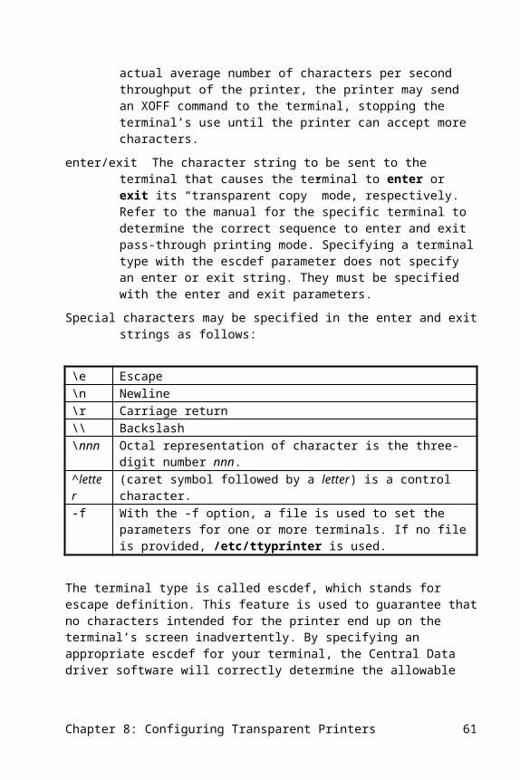
mxd tests # Name Description 8x2 8x4 Default0 tech tests The diagnostic enters a mode which accepts
interactive commands to peek and poke into 8x4 I/O and memory address space. A detailed description of the tech test commands follows this table.
X X
1 host adapter reset
Reset CPU, 8530s, 8237 and all host adapter functions.
X X X
2 blink LED Blink green led for 1 to 2 seconds. X X X3 DMA reg I/O Test 8237 register access from base CPU using
rotating ones and rotating zeros patterns.X X X
4 DMA reset Reset 8237. X X5 memory fill
onesFill specified memory addresses (-a option) with all ones and verify.
X X X
6 memory fill zeros
Fill specified memory addresses (-a option) with all zeros and verify.
X X X
7 memory address fill
Test memory over the specified range (-a option) using a unique address pattern.
X X X
8 memory walking ones/zeros
Test memory over the specified range (-a option) using a walking ones and zeros pattern. Note: this test will take a long time to run if the address range is large.
X X
9 SCC A reg I/O
Test 8530 register access from base CPU using rotating ones and rotating zeros patterns.
X X
10 SCC B reg I/O
Test 8530 register access from base CPU using rotating ones and rotating zeros patterns.
X X
11 SCC C reg I/O
Test 8530 register access from base CPU using rotating ones and rotating zeros patterns.
X X X
12 SCC D reg I/O
Test 8530 register access from base CPU using rotating ones and rotating zeros patterns.
X X X
13 async internal loop back A
Test async serial data transfer on 8530 channel A using programmed I/O and internal loop back modes.
X X
14 async internal loop back B
Test async serial data transfer on 8530 channel B using programmed I/O and internal loop back modes.
X X
15 async internal loop back C
Test async serial data transfer on 8530 channel C using programmed I/O and internal loop back modes.
X X X
16 async internal loopback D
Test async serial data transfer on 8530 channel D using programmed I/O and internal loopback modes.
X X X
17 DMA async internal loopback A
Test async serial data transfer on 8530 channel A using DMA I/O and internal loopback modes.
X X
18 DMA async internal loopback B
Test async serial data transfer on 8530 channel B using DMA I/O and internal loopback modes.
X X
19 DMA async internal loopback C
Test async serial data transfer on 8530 channel C using DMA I/O and internal loopback modes.
X X X
20 DMA async internal
Test async serial data transfer on 8530 channel D using DMA I/O and internal loopback
X X X
Chapter 12: Troubleshooting 61
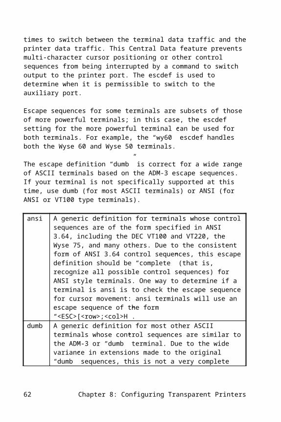
loopback D modes.21 DMA async
output AGenerate async data output on 8530 channel A using DMA I/O.
X X
22 DMA async output B
Generate async data output on 8530 channel B using DMA I/O.
X X
23 DMA async output C
Generate async data output on 8530 channel C using DMA I/O.
X X X
24 DMA async output D
Generate sync data output on 8530 channel D using DMA I/O.
X X X
25 external loopback A <-> C
Sends characters between channel A and C, using DMA I/O and async mode at 19.2K baud. Note: This test requires a standard host cable be installed connecting channel A and channel C. This test also requires running test 4 prior to executing this test.
X
26 external loopback B<-> D
Sends characters between channels B and D, using DMA I/O and async mode at 19.2K baud. Note: This test requires a standard host cable be installed connecting channel B and channel D. This test also requires running test 4 prior to executing this test.
X
27 external loopback C<->D
Sends characters between channels C and D, using DMA I/O and async mode at 19.2K baud. Note: This test requires a standard host cable be installed connecting channel C and channel D. This test also requires running test 4 prior to executing this test.
X
28 host interrupt self
This tests the ability of the 8x4 host adapter to interrupt the base CPU.
X X X
29 start loop Start execution of the CPU in a very small loop at the startup vector.
X X X
30 nop loop Start execution of the CPU in a nop loop. X X X31 read/write
loopStart execution of the CPU in a memory read/write loop. The base CPU verifies the operation.
X X X
32 DMA io loop Start execution of the CPU in an I/O loop referencing the 8237. The base CPU verifies the operation.
X X
33 SCC io loop Start execution of the CPU in an I/O loop referencing the 8530. The base CPU verifies the operation.
X X X
34 interrupt Test the ability of the base to interrupt the 8x4 CPU.
X X X
35 bus lock Verify the proper operation of test and set memory operations.
X X X
62 Chapter 12: Troubleshooting
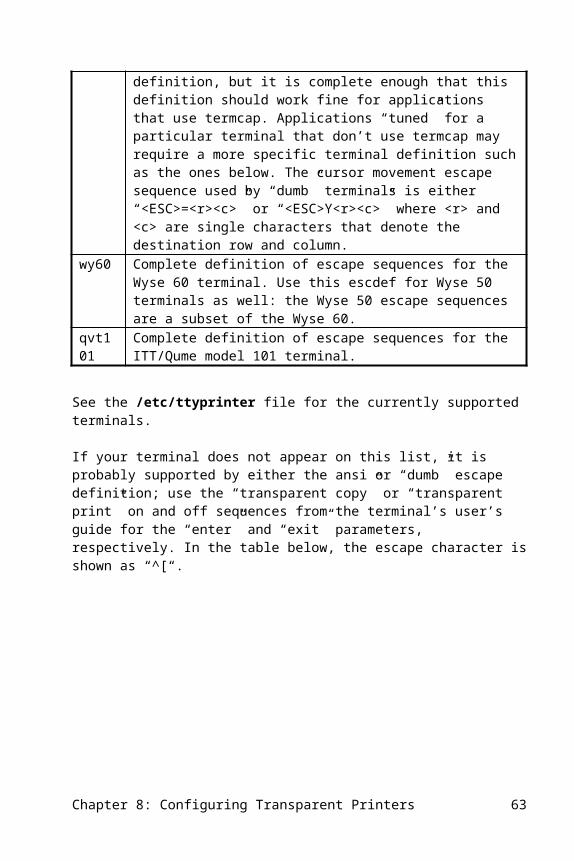
Tech Test CommandsDiagnostic test 0 enters a mode which provides interactive commands that allow “peeking and poking” into 8x2 and 8x4 I/O and memory address space:
/etc/8x4/mxd -b n 0
n is host adapter number 1 through 4.
An “*” prompt is output indicating tech test mode. All addresses specified are in hexadecimal and are relative to the particular host adapter indicated. The following commands are supported:
Command Argument Resultib ioaddr Input byte from ioaddr and printob ioaddr byte Output byte to ioaddrrb maddr Read byte from maddr and printwb maddr byte Write byte to maddrrw maddr Read word (16 bits) from maddr and
printww maddr byte Write word (16 bits) to maddrd maddr1 and maddr2 Display (print) from maddr1 to
maddr2f maddr1 and maddr2 byte Fill from maddr1 to maddr2 with byteq Quit the tech test modeL Loop on the next tech test command
Where:
ioaddr is a host adapter logical I/O address [0 through 1F]maddr is an host adapter memory address [0 through FFFF]byte is an 8-bit byte [two hex characters]word is 16 bits of data [four hex characters]
For example, to output the byte “A” to the an 8x2 or 8x4 Intelligent host adapter Control Register 1 (I/O location 15) on host adapter #3, first give the command:
/etc/8x4/mxd -b 3 0
You will see the tech. test prompt:
Chapter 12: Troubleshooting 63
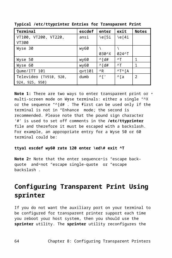
*
Now type:
ob 10 0
As an example of looping, to continually read the byte of data from memory address A5:
* L* rb a5*
To exit this loop mode, type the “interrupt“ character , usually Delete key or Control-C.
64 Chapter 12: Troubleshooting
13. Troubleshooting
Troubleshooting any sophisticated system involves breaking down the problem to isolate the problematic component. The components of the 8x4 Intelligent Multiport host adapter/terminal concentrator architecture are:
· Central Data 8x4 Intelligent Multiport software
· 8x4AT, 8x4GT, or 8x2AT host adapter
· Host adapter to terminal concentrator cable
· 8/tcII or 8/tcfmII terminal concentrator and its power source
· RS-232 cable from terminal concentrator to a terminal
· RS-232 cable from terminal concentrator to a modem (8/tcfmII only)
Other components are: the computer being used, the version of UNIX or XENIX installed on it, and the device being connected (i.e. terminal or modem).
What to CheckThe following lists the components you should check if your system is not working properly.
ComputerIs the computer supported by your operating system vendor? Did it operate reliably without Central Data products installed? What other host adapters are installed and might there be a conflict with the interrupt line selected for the 8x4 host adapter when the Central Data driver was installed?
Software (Other Than Central Data Software)Are gettys (logins) enabled on ports as desired? Without this, no login message will appear on a terminal. Are the baud rates set the same as the terminal’s? Note: UNIX requires ports to be “conditioned”. That is, if data is simply sent to a port by the cat command, there is no specification of the baud rate or other port attributes. The most
Chapter 12: Troubleshooting 65
common ways these attributes are set up is by the getty program which puts up the login message, or by a print spooler.
DriverDoes a Central Data copyright notice appear when the machine is first booted? If not, the driver may not be installed in the kernel. Do the names of the Central Data tty ports appear in the /dev or /dev/term directory? If not, a proper installation has not been completed.
8x2 and 8x4 Intelligent Multiport Host adaptersAlthough the 8x2AT and 8x4AT host adapters are half-length, they must be installed in a 16-bit ISA or EISA slot. Upon taking the system multi-user after booting, a message should appear on the console indicating that each installed host adapter is responding.
If the host adapter’s presence is not recognized, it may be due to problems with rotary switch settings or the computer’s cache as mentioned in the Hardware Installation chapter.
If a defective host adapter is suspected, run the mxd diagnostic, described in the previous chapter.
Host-to-Concentrator CableLittle is likely to go wrong with the supplied 10 foot cable used to connect the host adapter to a terminal concentrator. One way to isolate problems with a remote concentrator is to try the same unit locally connected. If it operates with the standard ten foot cable, but remotely only has a blinking HOST LED, the remote data connection is probably not correct. The host LED will stay on continuously when data packets are being received by the concentrator (the host adapters, once initialized by the host software, continually poll the concentrator even if no actual data is being transferred).
Terminal ConcentratorIs the concentrator receiving power? If so, the host LED should be either flashing or on steadily. On power-up, the concentrator goes through a self-test. All LEDs go on, then all the green LEDs go off, then the orange LEDs from 1 to 8 go off, all LEDs flash on, all go off, then they illuminate as normal. This leaves the host light flashing if no polling packets are being received from the host adapter or on steadily if polling packets are being received from the host adapter.
66 Chapter 12: Troubleshooting
If a problem is suspected with a particular port, try connecting the same device (and the same cable) to an alternate port. Of course, the software must also be changed to use the alternate port.
Cable to DeviceThe cable provided with the 8/tcII is designed to connect to a terminal. Two cables are provided with the 8/tcfmII that are designed to connect to a modem and a terminal (be sure that the correct one is used). Although the concentrator uses RS-232 which is an EIA standard, connecting one RS-232 device to another can often be more complicated and time consuming than originally imagined. When connecting a new RS-232 device, it is recommend that the manual for that device be consulted and a “breakout box” or other RS-232 hardware diagnostic tool be at hand.
Error MessagesBelow is a list of error messages that may occur when you are booting and the probable causes for the messages.
8x4 Intelligent Multiport: no host adapters foundThis message applies for all host adapters; these are four of the most likely reasons for this message:
· There is an address conflict between the 8x4 Intelligent Multiport host adapters and RAM or between the 8x4 Intelligent Multiport host adapters and each other. See the Hardware Installation chapter for more information on setting memory addresses. If your system has 12 or more megabytes of RAM, you must use the low memory addresses listed in the table (the “H” switch is set to 0). Be sure that each 8x4 host adapter has a different setting.
· Your system has cache which the 8x4 installation software is not aware of. Add the following as the first line of the /etc/8x4/mxrc file:
/etc/8x4/mxcfg -c 1
Alternately, try switching the rotary memory settings to 0A, 0B, 0C, 0D, or 0E.
· The bus speed of your computer must be 10 MHz or less. A very small number of clones run at faster speeds. There is no solution for this problem.
Chapter 12: Troubleshooting 67

· The 8x4 host adapter is bad. If you have another 8x4 host adapter available, configure it exactly like the one that seems to be bad and install it in your system.
8x2 n, or 8x4 n: diagnostic failedThe diagnostic that runs on the host adapter as it is booting up has failed. It applies to all host adapters. This may be because there is a partial memory address conflict. If so, try other memory switch settings. If that does not fix the problem, then the host adapter is bad. Please contact Central Data or your distributor for a replacement.
8x2 n, or 8x4 n: firmware not responding or firmware panicThe firmware failed to run or died. The most likely cause of this is a system address conflict or a bad host adapter. Try using a different switch setting. This diagnostic applies to all host adapters.
The “Host” Light Flashes ContinuouslyThis indicates that the 8x2 or 8x4 host adapter is unable to communicate with the terminal concentrator. Before trying any of the following remedies, unplug any terminals from the jacks on the terminal concentrator.
The most common reason for this problem is that the 8x4 Intelligent Multiport firmware failed to load and run. Make sure that your system is multi-user, that the green LED on the 8x4 Intelligent Multiport host adapter is flickering or dim, and that the following system message appeared on the screen.
8x4 Intelligent Multiport: n host adapters found
If this message has not appeared on the screen then see previous troubleshooting sections. Otherwise, the following problems might be indicated:
· A bad host cable. Use the host cable that came with your 8x2 or 8x4 host adapters.
· If you are sure the cable is all right, try connecting the terminal concentrator to another channel on the host adapter.
· If you have more than one host adapter in your system, try connecting the terminal concentrator to another host adapter and see if it corrects the problem.
68 Chapter 12: Troubleshooting
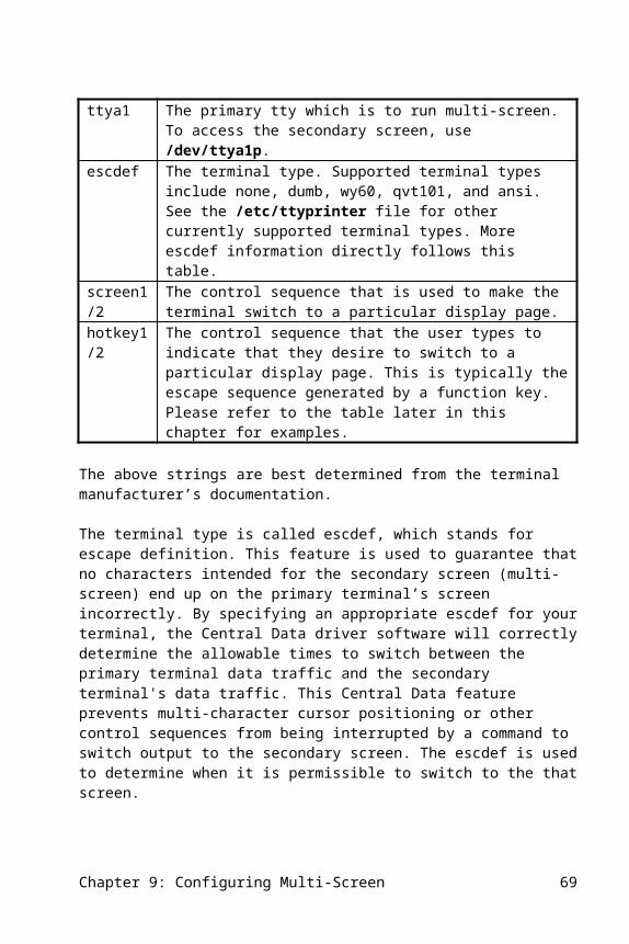
A Terminal Is Not WorkingIf the boot process completes, the HOST LED is on, but a terminal is not working, be sure that the terminal concentrator is connected to the correct channel on the 8x2 or 8x4 host adapter. Reminder: the connector closest to the green LED is A; the farthest is D.
· Try attaching the terminal with the RS-232 cable that came with the 8x2 or 8x4 adapter. If the terminal concentrator is an 8/tcfmII, be sure that you are using a terminal cable (not a modem cable) with the terminal.
· The green light should be solid. If it is blinking, the operating system has not opened that port. Make sure that the terminal is enabled.
· The yellow light should blink when any key on the terminal is pressed. Try pressing Enter a few times while watching the yellow light.
· If you are using your own cable, it is possible that you reversed some of the leads in the cable. Check the pinout specification in the terminal concentrator manual carefully. Note that the pinouts for the 8/tcII and 8/tcfmII are different.
Garbage Characters on the ScreenCheck the length of your RS-232 cable from the terminal concentrator: it should be no longer than 50 feet. Be sure that the ground pins are connected. Try lowering the baud rate. If the problem goes away, then it is a cable type or length problem. Also, try a low-capacitance cable.
Some terminals, like the Wyse 60, require flow control which may not be working or is not set up correctly. Make sure that the terminal is using software flow control in the setup (such as if XON/XOFF is activated).
Chapter 12: Troubleshooting 69

The Concentrator Does Not Stay On-lineThe most common cause of this problem is that there is a ground loop problem in your electrical system. An easy way to determine if this is the situation is to disconnect the terminals one by one from the terminal concentrator and see if the problem goes away. You can alleviate this problem by plugging the terminals into the same circuit as the computer system.
The problem can also occur if you have some equipment which has high power requirements (such as a copier) connected to the same circuit as your terminal or optional power supply. When the copier becomes active, a ground shift is created. To remedy, connect this power-intensive device to a different electrical circuit.
This problem can also surface if you are using your own extender cable to attach the terminal concentrator to the 8x2 or 8x4 host adapter. If this is the case, be sure that the extender cable uses a twisted pair and is fully shielded: telephone wire will not work reliably.
A Serial Printer Gives No OutputPrinters have many more things that can go wrong than do terminals. The first step in checking this problem is to disconnect the printer and attach a terminal to the same port. If the terminal displays text on the screen, the problem is in your printer or in the printer’s internal setup program. Since printers often require different cables than terminals, try using the Central Data terminal cable with the printer. If the printer’s manual indicates that it requires hardware flow control (not simply XON/XOFF), then you need to attach it to an 8/tcfmII terminal concentrator or use the DCD signal of the tcII terminal concentrator with the mxstty dcdflow command.
Serial Printer Prints Garbage CharactersThis is most likely due to flow control problems. Be sure that the printer’s flow control matches the flow control you set with the stty program. If the printer uses software flow control, use the mxstty program instead of the UNIX stty program. The printer may not be sending any flow control characters. While the printer is printing, watch the yellow LED on the terminal concentrator. Blinking indicates the printer sent a character. Not blinking indicates the printer did not send a flow control character. Check the physical printer set up.
70 Chapter 12: Troubleshooting

The printer may be sending the wrong flow control characters. Check the character length and the parity of the printer. Make sure that it matches the system by issuing an stty command while printing or refer to the spooler interface file.
If you are not using the print spooler, hold the printer open by removing the comment field and modifying the commands in the mxrc file that comes with the 8x4 software. If your printer has hardware flow control, be sure the line that the printer uses to do the hardware handshaking is connected to the CTS input on the terminal concentrator.
Technical SupportWhen calling for technical assistance, please have the following information available:
· Revision of Central Data driver software (printed on diskette),
· Status of indicator LEDs on 8x4 and terminal concentrators,
· Whether any diagnostics have been run and what the results were,
· Name of the operating system and its version number.
Chapter 12: Troubleshooting 71
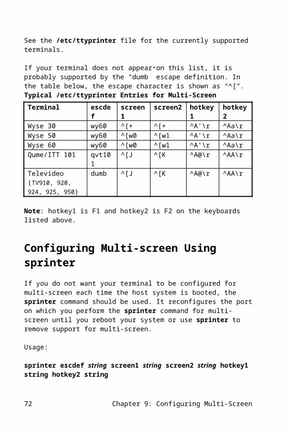
Appendix A. Demonstration Software
This appendix describes the demonstration software provided with the Central Data 8x4 software.
If DEMO or ALL were selected at installation time, the Central Data demonstration software was loaded in a directory called /mxdemo. If disk space is needed, the entire contents of this directory may be deleted using custom to remove the Central Data package called “DEMO”.
The demo software should not be run while logged in as root. Add an account called “guest” to the system using mkuser, log in as “guest”, and change to the /mxdemo directory.
If you are logged on as root, you must use the full path name of these utility programs to execute them. For example:
./starttys
or you will get a message like:
starttys: not found
even though it is there.
TTY Output Speed BenchmarkThese scripts will show the performance of the character I/O system.
Several terminals are required to run this demo. The more terminals the better.Any terminals that do not have a login enabled should be set to 9600 baud, 8-bit, no parity.
If a different baud rate test is desired, that can be indicated on the command line. For example:
Appendix A: Demonstration Software 73
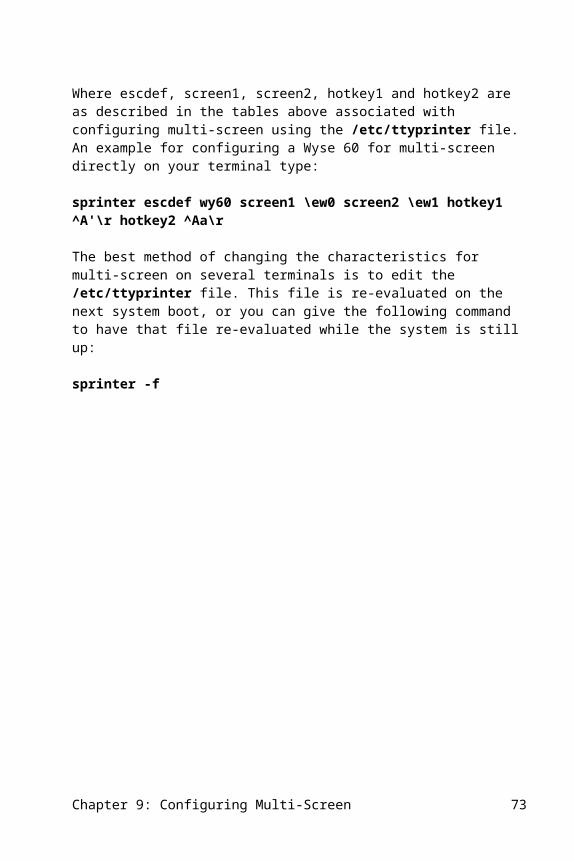
starttys -1200 a1 -19200 a2
will use 1200 baud for ttya1 and 19.2K baud for output to ttya2.
The starttys shell script starts background processes that continuously output to each terminal. A special program is used to generate infinite output while timing and counting output characters.
The stopttys shell script will stop all output and print a summary of the output performance.
Log in the console as “guest” and change to the /mxdemo directory.
Recommended ProcedureGive the command:
starttys l1 l2 l3 ... ln
where ln is a terminal number. For example, if there are terminals connected to port 1, port 2, port 3, and port 4 of the terminal concentrator connected to channel A of 8x4 host adapter 1, then the ttys are ttya1, ttya2, ttya3, ttya4. Give the command:
starttys a1 a2 a3 a4
The terminals listed should start displaying text as the test program is running.Allow the terminals to run for a while (at least 30 seconds). The longer the terminals run, the more accurate the results. Note that all terminals should output at full speed, concurrently, and with no hesitation.
After at least 30 seconds, give the command:
stopttys
After several seconds, the program will stop sending data to the terminals, and a summary of the results will be displayed. The number of characters per second should be nearly the maximum possible for the baud rate of the terminal. For example, a terminal at 9600 baud should be able to output 960 characters/second.
This test may be run without terminals by using the lowercase letter versions of the tty names. With the lowercase versions, no actual terminals need be connected. These scripts can be used to test any serial port, not just terminal concentrator ports.
74 Appendix A: Demonstration Software
Appendix B. File List
This appendix lists the files included with the 8x4 software. Please note that this list may be somewhat out of date based on recent releases of the software, but should provide a general idea of the files that are on the distribution media and the directories they will be copied to upon installation.
SVR3 & XENIX:rw-r--r-- 0/0 1421 Mar 19 09:00 1996 ./tmp/perms/8x4rwxr-xr-x 0/0 330 Mar 19 09:00 1996 ./tmp/init.8x4rw-r--r-- 0/0 0 Mar 19 09:00 1996 ./tmp/_lbl/prd=8x4/typ=all86/rel=1.5.7/vol=01rw-r--r-- 0/0 23888 Mar 19 09:00 1996 ./etc/8x4/mxkern4rw-r--r-- 0/0 23132 Mar 19 09:00 1996 ./etc/8x4/mxkern2rw-r--r-- 0/0 23194 Mar 19 09:00 1996 ./etc/8x4/mxkern1rw-r--r-- 0/0 23380 Mar 19 09:00 1996 ./etc/8x4/mxkerngtrw-r--r-- 0/0 24232 Mar 19 09:00 1996 ./etc/8x4/mxkernelr--r--r-- 0/0 4793 Mar 19 09:00 1996 ./etc/8x4/READMErwxr-xr-x 0/0 1394 Mar 19 09:00 1996 ./etc/8x4/installr--r--r-- 0/0 9202 Mar 19 09:00 1996 ./etc/8x4/install.shr--r--r-- 0/0 3760 Mar 19 09:00 1996 ./etc/8x4/remove.shrwxr-xr-x 0/0 1389 Mar 19 09:00 1996 ./etc/8x4/mxrcrw-r--r-- 0/0 351 Mar 19 09:00 1996 ./etc/8x4/profile.shrw-r--r-- 0/0 930836 Mar 19 10:05 1996 ./etc/8x4/tar.file.zrw-r--r-- 0/0 1072 Mar 19 09:00 1996 ./etc/escdefrw-r--r-- 0/0 2708 Mar 19 09:00 1996 ./usr/include/amxioctl.hrwxr-xr-x 0/0 93 Mar 19 09:00 1996 ./usr/lib/custom/8x4.rmvr--r--r-- 0/0 4720 Mar 19 09:00 1996 ./mxdemo/data1r--r--r-- 0/0 6179 Mar 19 09:00 1996 ./mxdemo/data2r--r--r-- 0/0 1886 Mar 19 09:00 1996 ./mxdemo/data3r--r--r-- 0/0 4279 Mar 19 09:00 1996 ./mxdemo/data4rw-r--r-- 0/0 2430 Mar 19 09:00 1996 ./mxdemo/modem.cr--r--r-- 0/0 600 Mar 19 09:00 1996 ./mxdemo/starttysr--r--r-- 0/0 161 Mar 19 09:00 1996 ./mxdemo/stopttysr--r--r-- 0/0 249 Mar 19 09:00 1996 ./mxdemo/sum.awkrwxr-xr-x 0/0 17156 Mar 19 09:00 1996 ./mxdemo/ttrw-rw-rw- 0/0 0 Mar 19 09:00 1996 ./mxdemo/PIDSrw-rw-rw- 0/0 0 Mar 19 09:00 1996 ./mxdemo/TOTALS
UNIX SVR4:-rw-r--r-- 11912 Dec 15 09:09 ./etc/8x4/amx.d/amx.e-rw-r--r-- 12136 Dec 15 09:10 ./etc/8x4/amx.d/amx.v-rw-r--r-- 12044 Dec 15 09:09 ./etc/8x4/amx.d/amx.p-rw-r--r-- 11332 Dec 15 09:09 ./etc/8x4/amx.d/amx.b-rw-r--r-- 10688 Dec 15 09:09 ./etc/8x4/amx.d/amxmc.e-rw-r--r-- 10908 Dec 15 09:09 ./etc/8x4/amx.d/amxmc.v-rw-r--r-- 10816 Dec 15 09:09 ./etc/8x4/amx.d/amxmc.p-rw-rw-r-- 32 Dec 15 09:09 ./etc/8x4/amx.d/Master-rw-rw-r-- 34 Dec 15 09:09 ./etc/8x4/amx.d/Master.b-rw-rw-r-- 23 Dec 15 09:09 ./etc/8x4/amx.d/System-rw-rw-r-- 29 Dec 15 09:09 ./etc/8x4/amx.d/Rc-rw-rw-r-- 295 Dec 15 09:09 ./etc/8x4/amx.d/Rc.b-rw-rw-r-- 369 Dec 15 09:09 ./etc/8x4/amx.d/Shutdown-rw-rw-r-- 417 Dec 15 09:09 ./etc/8x4/amx.d/Shutdown.b-rw-r--r-- 26160 Dec 15 09:09 ./etc/8x4/mxc.d/mxcs.e-rw-r--r-- 27136 Dec 15 09:09 ./etc/8x4/mxc.d/mxcs.v
Appendix B: File List 75

-rw-r--r-- 26552 Dec 15 09:09 ./etc/8x4/mxc.d/mxcs.p-rw-r--r-- 26868 Dec 15 09:09 ./etc/8x4/mxc.d/mxcs.b-rw-rw-r-- 32 Dec 15 09:10 ./etc/8x4/mxc.d/Master-rw-rw-r-- 34 Dec 15 09:09 ./etc/8x4/mxc.d/Master.b-rw-rw-r-- 24 Dec 15 09:09 ./etc/8x4/mxc.d/System-rw-r--r-- 747 Dec 15 09:09 ./etc/8x4/mxc.d/space.e-rw-r--r-- 747 Dec 15 09:10 ./etc/8x4/mxc.d/space.v-rw-r--r-- 747 Dec 15 09:10 ./etc/8x4/mxc.d/space.p-rw-r--r-- 665 Dec 15 09:10 ./etc/8x4/mxc.d/space.b-rw-r--r-- 2200 Dec 15 09:10 ./etc/8x4/mxp.d/mxcsp.e-rw-r--r-- 2308 Dec 15 09:10 ./etc/8x4/mxp.d/mxcsp.v-rw-r--r-- 2308 Dec 15 09:10 ./etc/8x4/mxp.d/mxcsp.p-rw-r--r-- 2592 Dec 15 09:10 ./etc/8x4/mxp.d/mxcsp.b-rw-rw-r-- 32 Dec 15 09:10 ./etc/8x4/mxp.d/Master-rw-rw-r-- 34 Dec 15 09:10 ./etc/8x4/mxp.d/Master.b-rw-rw-r-- 24 Dec 15 09:10 ./etc/8x4/mxp.d/System-rw-r--r-- 23880 Dec 15 09:10 ./etc/8x4/mxkern4-rw-r--r-- 23116 Dec 15 09:10 ./etc/8x4/mxkern2-rw-r--r-- 22778 Dec 15 09:10 ./etc/8x4/mxkern1-rw-r--r-- 23372 Dec 15 09:10 ./etc/8x4/mxkerngt-rw-r--r-- 24216 Dec 15 09:10 ./etc/8x4/mxkernel-rwxr-xr-x 43796 Dec 15 09:10 ./etc/8x4/mxd-rwxr-xr-x 43508 Dec 15 09:10 ./etc/8x4/mxl-rwxr-xr-x 37748 Dec 15 09:10 ./etc/8x4/mxdmp.v-rwxr-xr-x 37672 Dec 15 09:10 ./etc/8x4/mxdmp.p-rw-rw-rw- 2328 Dec 15 09:10 ./etc/8x4/mxenable.v-rw-rw-rw- 2096 Dec 15 09:10 ./etc/8x4/mxdisable.v-rw-rw-rw- 2272 Dec 15 09:10 ./etc/8x4/mxenable.4-rw-rw-rw- 2111 Dec 15 09:10 ./etc/8x4/mxdisable.4-rwxr-xr-x 7088 Dec 15 09:10 ./etc/8x4/ttyadd.4-rw-rw-rw- 4116 Dec 15 09:10 ./etc/8x4/install.e-rw-rw-rw- 4124 Dec 15 09:10 ./etc/8x4/install.v-rw-rw-rw- 4756 Dec 15 09:10 ./etc/8x4/install.b-rw-rw-rw- 4121 Dec 15 09:10 ./etc/8x4/install.p-rwxr-xr-x 41704 Dec 15 09:10 ./etc/8x4/mxcfg-rw-rw-rw- 1671 Dec 15 09:10 ./etc/8x4/README-rw-rw-rw- 1415 Dec 15 09:10 ./etc/8x4/ttyd.hdr-rw-rw-rw- 2459 Dec 15 09:10 ./etc/8x4/ttyp.hdr-rw-rw-rw- 1389 Dec 15 09:10 ./etc/8x4/mxrc-rw-rw-rw- 569 Dec 15 09:10 ./etc/8x4/autop-rw-rw-rw- 19395 Dec 15 09:10 ./etc/8x4/@707D.ADF-rw-rw-rw- 9013 Dec 15 09:10 ./etc/8x4/!ISAC002.CFG-rw-rw-rw- 1398 Dec 15 09:10 ./etc/8x4/mxcrestore-rwxr-xr-x 37672 Dec 15 09:10 ./etc/8x4/mxdmp.e-rwxr-xr-x 38060 Dec 15 09:10 ./etc/8x4/mxdmp.b-rw-r--r-- 1072 Dec 15 09:10 ./etc/escdef-rw-rw-r-- 2708 Dec 15 09:09 ./usr/include/amxioctl.h-rwxr-xr-x 10892 Dec 15 09:10 ./usr/bin/mxstty-rwxr-xr-x 10060 Dec 15 09:10 ./usr/bin/sprinter-rw-r--r-- 133 Dec 15 09:10 ./pkginfo-rw-r--r-- 17736 Dec 15 09:10 ./request-rw-r--r-- 13250 Dec 15 09:11 ./postinstall-rw-r--r-- 5611 Dec 15 09:10 ./preremove-rw-r--r-- 4476 Dec 15 09:10 ./postremove-rw-rw-rw- 51 Dec 15 09:10 ./space-rw-rw-rw- 4117 Dec 15 09:10 ./prototype
76 Appendix B: File List

Index/dev directory, 19, 25, 32/etc/8x4/mxrc, 52/etc/rc, 52/etc/ttydefault file, 49/etc/ttyprinter file, 37/etc/ttys file, 19/mxdemo directory, 71/mxdemo/modem.c, 548/tcfmII
flow control, 5180188 processor, 380286 processor, 38x1DC
troubleshooting, 648x2
introduction, 3specifications, 55troubleshooting, 64
8x4description, 3specifications, 55troubleshooting, 64
8x4GTintroduction, 3specifications, 55
ansi, 39, 45cables
troubleshooting, 65cache, 5concentrator-to-host cable, 64CTS/RTS, 35ctsflow, 51dcdflow, 48demonstration software, 71device driver, 7, 64diagnostic, 57
interactive, 61diagnostic failed message, 66dumb, 39, 45enable command
XENIX, 19error messages, 65escdef, 38, 44firmware loader, 51
firmware not responding message, 66flow control, 35garbage characters, 67, 68gettydef, 19haltsys command, 17hardware handshake, 35hardware installation, 9hibaud, 49, 50host-to-concentrator cable, 64init 2 command, 21, 23, 27, 29installation
beginning letter, 17, 28number of concentrators, 17overview, 7software, 27
SVR3, 21XENIX, 15
installpkg program, 21ixon, 47Link Kit, 15lockioctl, 48lpinit program, 35memory cache, 5memory requirements, 5mini-DIN, 64model numbers, 73multi-screen, 43, 47mxcfg program, 53mxd program, 47, 57mxkern1, 53mxkern2, 53mxkern4, 53mxkernel, 53mxkerngt, 53mxl program, 51mxstty program, 47, 51, 68no boards found message, 65onlcr, 35output speed, 71part numbers, 73peek, 61pkgadd program, 27poke, 61printers, 35
spooling, 35transparent, 37, 40troubleshooting, 68
qvt101, 39, 45RS-422, 3rtsflow, 51
Index 77

serial printers, 35shutdown command, 23, 29software
demostration, 71diagnostic, 57utility, 47
software installation, 27SVR3, 21XENIX, 15
spooling programs, 35sprinter, 47
multi-screen, 46transparent printer, 40
sprinter program, 46starttys, 72stopttys, 72stty program, 47, 51, 68su command, 15, 21, 27sysadm program, 25System requirements, 5technical support, 69terminal concentrator
troubleshooting, 64terminal naming conventions
multi-screen, 18, 24, 29, 31transparent print, 18, 24, 29, 31
terminalsactivating, 19troubleshooting, 67
transparent printing, 37, 40troubleshooting, 63uninterruptable power supplies, 54utility software, 47wy60, 39, 45XON/XOFF, 35, 47Z80-type processor, 4
78 Index