hot water generator model wcc12 - trevor …trevormartin.com/documents/hwg_man_wcc12.pdf · if...
TRANSCRIPT

INSTALLATION INSTRUCTIONS
FOR
HOT WATER GENERATOR
MODEL WCC12

Table of Contents 1. Introduction
2. Specifications
3. Locating the Unit
4. Installation
a. Before Starting
b. Plumbing Connections
c. Electrical Connections
d. Air Side Connections
5. System Startup
6. Diagrams and Figures
a. Figure 1 - Heat Pump Dimensions and Connections
b. Figure 2 - Plumbing Schematic
c. Figure 3 -- Electrical Connections
d. Figure 4 - Wiring Schematic
7. Warranty Information
Revised 03/22/2005
(1)
1. Introduction The Hot Water Generator is a high efficiency appliance that heats domestic hot water by removing heat from the surrounding air. Unlike other water heaters, the unit is designed to be able to deliver cool, dehumidified air to the living space whenever there is a call for water heating. Based an average water usage of 64 gallons per day, the Hot Water Generator can provide up to 30,000 BTUs of free cooling. The Hot Water Generator uses a conventional electric water heater as a storage tank. The unit uses the thermostats and limits in the electric water heater to simplify the installation. If the air temperature entering the unit goes below 50º F, the unit will automatically switch to conventional electric resistance water heating. The Hot Water Generator has specific installation instructions that must be followed. Before beginning the installation, read the entire instructions on both the Hot Water Generator and the electric water heater, and follow all local building, electrical and plumbing codes. The unit must be installed by qualified professionals only.
(2)

2. Specifications 12,000 BTU/HR Water Heating Capacity 28 gal. / HR @ 70º to 120º F rise* Max. Tank Temp. - 130º F COP - 3.0 Energy Factor - 2.6 9,000 BTU/HR Air Cooling Capacity 2.2 Pints/HR Dehumidification Capacity Air Flow- 1/18th HP blower 350 CFM @ 0 in. external static on low speed 350 CFM @ 0.3 in. external static on high speed Minimum air inlet temperature - 50º F Return air duct connection - 12" X 14" Supply air duct connection - 6" X 8" 208 / 230 Volt AC, 1 Phase, 60 Hz. 6 Amps Full Load Max. water side working pressure - 150 psi Weight: 90 lbs.
• Performance based on 80º dry bulb / 67º wet bulb inlet air temperature
(3)
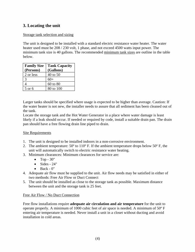
3. Locating the unit Storage tank selection and sizing The unit is designed to be installed with a standard electric resistance water heater. The water heater used must be 208 / 230 volt, 1 phase, and not exceed 4500 watts input power. The minimum tank size is 40 gallons. The recommended minimum tank sizes are outline in the table below. Family Size (Persons)
Tank Capacity (Gallons)
2 or less 40 to 50 3 60+ 4 60 to 80 5 or 6 80 to 100
Larger tanks should be specified where usage is expected to be higher than average. Caution: If the water heater is not new, the installer needs to assure that all sediment has been cleaned out of the tank. Locate the storage tank and the Hot Water Generator in a place where water damage is least likely if a leak should occur. If needed or required by code, install a suitable drain pan. The drain pan should have a free flowing drain line piped to drain. Site Requirements 1. The unit is designed to be installed indoors in a non-corrosive environment. 2. The ambient temperature: 50º to 110º F. If the ambient temperature drops below 50º F, the
unit will automatically switch to electric resistance water heating. 3. Minimum clearances: Minimum clearances for service are:
• Top - 30" • Sides - 24" • Back - 0"
4. Adequate air flow must he supplied to the unit. Air flow needs may be satisfied in either of two methods: Free Air Flow or Duct Connect
5. The unit should be installed as close to the storage tank as possible. Maximum distance between the unit and the storage tank is 25 feet.
Free Air Flow / No Duct Connection Free flow installations require adequate air circulation and air temperature for the unit to operate properly. A minimum of 1000 cubic feet of air space is needed. A minimum of 50º F entering air temperature is needed. Never install a unit in a closet without ducting and avoid installation in cold areas.
(4)

Duct Connection Applications When connecting the air inlet and outlet to a ducting system, design for 350 CFM at 0.3 inches of water maximum external static pressure, and wire the blower for high speed. The unit comes shipped for an unducted, free air flow application and with the blower wired for low speed. Condensate drain The unit can remove 3 or 4 pints of water per hour in high humidity sites. Condensate must be drained. If a gravity drain is not available, install a condensate pump. 4. Installation
WARNING
TO GUARD AGAINST SEVERE BURNS OR POSSIBLE FATAL ELECTRICAL SHOCK, BE SURE TO TURN OFF ELECTRICAL POWER TO THE WATER HEATER BEFORE REMOVING ANY PANELS. Before Starting The Hot Water Generator has specific installation instructions that must be followed. Before beginning the installation, read the entire installation instructions on both the Hot Water Generator and the electric resistance water heater, and follow all local building, electrical and plumbing codes. The installation should only be done by qualified professionals with the appropriate training and experience. Plumbing Connections The Hot Water Generator can be operated with most conventional residential electric water heaters used as a storage tank. Best performance will be achieved by installing a new tank with the unit. The electric water heater selected must be 4500 watts or less. Note: Turn off the electrical power and the water supply, and drain the tank if you are planning to retrofit the unit to an existing water heater. Inspect the tank. If there is any sediment collected on the bottom of the tank, it is the responsibility of the installer to assure that it has been completely flushed out.
(5)

WARNING
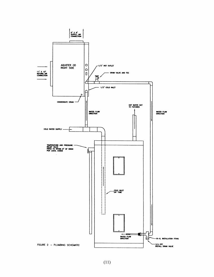
WATER FROM THE DRAIN HOSE MAY BE VERY HOT. BE SURE NO ONE IS NEAR THE DRAIN HOSE OR THEY COULD GET BURNED SEVERELY. WATER FROM THE RELIEF VALVE DRAIN PIPE MAY BE VERY HOT. MAKE SURE NO ONE IS NEAR THE PIPE OR THEY COULD GET BURNED SEVERELY. A typical plumbing schematic is shown in Figure 2. The Hot Water Generator is designed to pump cold water out of the storage tank, and return warm water back to the tank. The unit is piped in parallel with the cold and hot water piping. The following guidelines must be followed: 1. The distance between the unit and the tank cannot exceed 25 feet. Minimize the distance and
elbows. 2. The cold inlet and hot outlet connections on the unit are 1/2" NPT nominal pipe can be used
between the unit and the storage tank. 3. Piping between the unit and the tank must be free of any restrictions of any kind. No shutoff
valves can be installed between the unit and the tank. As shown in figure 2, the Hot Water Generator is piped in parallel with the tank. Be sure to install a drain coupling, Nibco #701 -D or equivalent on the Hot Water Generator hot water outlet pipe. This will save you a lot of time at startup.
4. Install a new temperature and pressure relief valve on all retrofit installations. 5. Follow all installation and safety instructions provided with the electric water heater.
WARNING If the temperature and pressure relief valve needs replacing, use only a valve specified by local codes, but not less than the combination temperature and pressure relief valve certified by a nationally recognized testing laboratory that maintains periodic inspection of production of listed equipment or materials meeting the requirements for Relief Valves and Automatic Gas Shutoff Devices for Hot Water Supply Systems, as specified in the latest edition of ANSI Z21.11. The replacement valve must be marked with a maximum set pressure not to exceed the maximum working pressure of the water heater as indicated on the rating plate. Install the replacement valve into the opening provided and marked for this purpose on -the water heater. Do not place any valve between the temperature and pressure relief valve and the tank. Orient it or provide tubing so that any discharge from the valve will exit only within 6 inches above a suitable drain. The discharge opening must not be blocked or reduced in size under any circumstances. 6. Insulate all piping between the unit and the tank.
(6)

Electrical Connections The Hot Water Generator control system uses the thermostats provided with the electric water heater to control the water temperature. The unit will automatically switch to electric water heating if the air temperature to the unit drops below 50º F. Because the unit is controlling the electric water heater and its elements, the wiring to the Hot Water Generator must be sized to handle the electric water heater input power.
WARNING IF YOU ARE NOT FAMILIAR WITH WIRING AND YOU HAVE ANY DOUBTS, YOU SHOULD GET HELP FROM A LICENSED ELECTRICIAN. IF YOU DO SOMETHING WRONG, SEVERE BURN OR SHOCK HAZARDS CAN RESULT. BE SURE TO FOLLOW LOCAL AND NATIONAL CODES AND ELECTRIC UTILITY REQUIREMENTS WHEN MAKING CONNECTIONS. CAUTION: BE SURE TO PROPERLY GROUND THE ELECTRIC WATER HEATER AND THE HOT WATER GENERATOR UNIT. Note: Turn off the power. Follow all local electrical codes and requirements. See Figure 3, Electrical Connections, and Figure 4, Wiring Schematic. 1. Check the specifications on the electric water heater. The unit must be 208 / 230 volt, 1
phase, 60 Hz., with an input power of 4500 watts on less. 2. Remove the service panel on the right side of the unit. Locate the control panel. Wires L1,
L2, T1, and T2 are below the control panel. Power to the Hot Water Generator CAUTION: If you are using wiring from the old water heater, and it is aluminum, replace it with copper wiring. Line voltage is connected to the two black wires marked L1 and L2 below the control panel. Use a 2 - wire conductor and a ground from a properly sized breaker.
(7)

Power to the Electric Water Heater Power to the electric water heater is connected to the two blue wires marked T1 and T2 below the control panel. Use a 2 - wire conductor and a ground. Connect the other end to the input power connections on the electric water heater. Assure that the unit is properly grounded and all wiring conforms to local electrical codes. Do not turn power on until the tank is full of water and the unit has been purged of air. Damage will result almost immediately. Air Side Connections Adequate airflow must be supplied to the unit. The supply air connection is located at the top of the unit. Return air enters from the front of the unit. Refer to the requirements outlined in Section 3, Locating the unit, Site Requirements. 5. System Fill and Startup After completing all plumbing, electrical, and duct connections, the unit and the storage tank are ready to be filled with water. 1. Be sure the drain valve on the storage tank and the drain coupling on the outlet pipe of the
Hot Water Generator are closed. 2. Open a hot water faucet to allow air to vented from the system. 3. Open the cold water supply, and the unit and the storage tank will begin to fill with water. 4. When the water flow from the faucet is smooth and free of bubbles, close the faucet. 5. Check all connections for leaks. 6. Open the bleed on the drain coupling that you installed on the hot water outlet of the Hot
Water Generator, and bleed out any air in the unit. 7. Be sure the electrical power is off. Check the set points of the thermostats on the electric water heater. These thermostats control the water temperature in both the heat pump mode and the electric water heating mode.
(8)

WARNING
WATER TEMPERATURE OVER 125º FAHREHEIT CAN CAUSE BURNS OR DEATH FROM SCALDS. CHILDREN, DISABLED AND ELDERLY ARE AT HIGHER RISK OF BEING SCALDED. ALWAYS FEEL WATER TEMPERATURE BEFORE BATHING OR SHOWERING. TEMPERATURE LIMITING VALVES WITH INSTRUCTIONS ARE AVAILABLE FROM PLUMBING SUPPLY AND HARDWARE STORES.
To comply with most safety regulations, set thermostats no higher than 120º F. A setting of 120º F will satisfy most households. 8. The electric / heat pump switch is located on the right side of the unit. Switch the unit to the
"Heat Pump" position. Assure that all electrical connections are done and the unit is properly grounded. Turn the power on at the breaker. The unit should start immediately. When the unit is running, the compressor, blower and circulator pump will start.
9. While the unit is running, open the bleed on the drain coupling that you installed on the hot
water outlet of the Hot Water Generator, and bleed any remaining air out of the unit. 10. Check the unit for normal operation. Normal operating parameters are:
Water temperature rise: 15º to 20º F Air temperature drop: 10º to 15º F - No duct connect installations
15º to 20º F - Duct connect installations Electrical: Current in the 4.0 to 5.5 Amps @ 230 Volts
11. Switch the electric/heat pump switch to the "electric" position. Refer to the specifications and
instructions on the electric water heater and check for normal operation. 12. Switch the electric/heat pump switch to the "heat pump" position. The unit should remain in
the electric mode until the thermostat is satisfied. On the next call for heat, the unit will start in the heat pump mode.
(9)

(10)
(11)

1. Remove right side panel 2. Connect power from breaker to L1, L2 and Ground 3. Connect power to electric water heater to T1, T2 and Ground
FIGURE 3 – ELECTRICAL CONNECTIONS SHOWING RIGHT SIDE
WITH PANEL REMOVED
(12)

FIGURE 4 – WIRING SCHEMATIC
(13)

LIMITED WARRANTY:
ALL products are warranted against defects in workmanship and materials for 12 months
from date of installation. In the absence of suitable proof of date of installation (Bill of Sale), the
specified warranty period will commence 30 days after the date of manufacture. This constitutes
the only warranty in connection with this sale, and is in lieu of all other warranties, expressed or
implied, written, or oral. THERE ARE NO IMPLIED WARRANTIES OF
MERCHANTABILITY OR FITNESS FOR A PARTICULAR PURPOSE THAT APPLY TO
THIS SALE. The pump cartridge has a three-year limited warranty. The Trevor-Martin
Corporation heat exchanger has a five-year limited warranty.
No employee, agent, dealer or other person is authorized to give any warranties on behalf
of Trevor-Martin Corporation, nor to assume for Trevor-Martin Corporation any other liability in
connection with any of their products, except as authorized by an officer of Trevor-Martin
Corporation, in a signed written document. Units not protected against freezing are not
warranted.
LIMITATION OF REMEDY:
Trevor-Martin Corporation will replace or repair, at Trevor-Martin Corporations option,
F.O.B. Factory, freight prepaid, any product, defective in workmanship or material if such
product is returned to our plant, freight prepaid, within 12 months of date of installation. It is
agreed that such replacement or repair is the exclusive remedy available from Trevor-Martin
Corporation should any of our products prove to be defective. Trevor-Martin Corporation is not
liable for labor charges or damage of any sort whatsoever, including incidental and consequential
damages. Product returns, under the terms of this warranty, must be approved by Trevor-Martin
Corporation. Products or parts thereof replaced or repaired under the conditions of this warranty
will be returned, transportation charges prepaid within the United States by best and most
economical means.
Trevor-Martin Corporation 4151 112th Terrace North • Clearwater, FL 33762
(14)