hot water on demand installation and operation...
TRANSCRIPT

www.atmor.net
Hot Water on Demand
Installation and Operation Guide900 Series InLine
3kW-13kW

OVERVIEWThis manual must be read carefully before attempting to install the water heater. If you do not follow the safety rules or the instructions outlined in this manual, the unit may not operate properly and it could cause property damage, serious bodily injury or death.
Atmor will not be liable for any damages because of failure to comply with the installation and operating instructions outlined in this manual or because of improper use. Improper use includes the use of this appliance to heat any liquid other than water. Failure to comply with the installation and operating instructions or improper use voids the warranty. Never remove the unit’s cover unless the electricity is turned off.
Safety Instructions
1
01
04
07
03
06
09
02
05
08
The water heater must be installed by a licensed electrician and in compliance with all local electrical and building regulations.
The heater must be installed according to the installation instructions (see figures).
The plumbing installation requires metal or reinforced pipes that can withstand a minimum pressure of 8 bar. (Other types of pipes will cause damage.)
Caution: The appliance must be grounded.
The plumbing installation must be completed before the electrical installation.
Do not install the heater where it may be subjected to direct sunlight, rain and/or a constant spray of water.
A dedicated circuit breaker must be installed on the power distribution panel.
The heater operates at a minimum water flow rate of 0.5 gallon/minute.
Always contact your local authorized licensed proffessional for service.
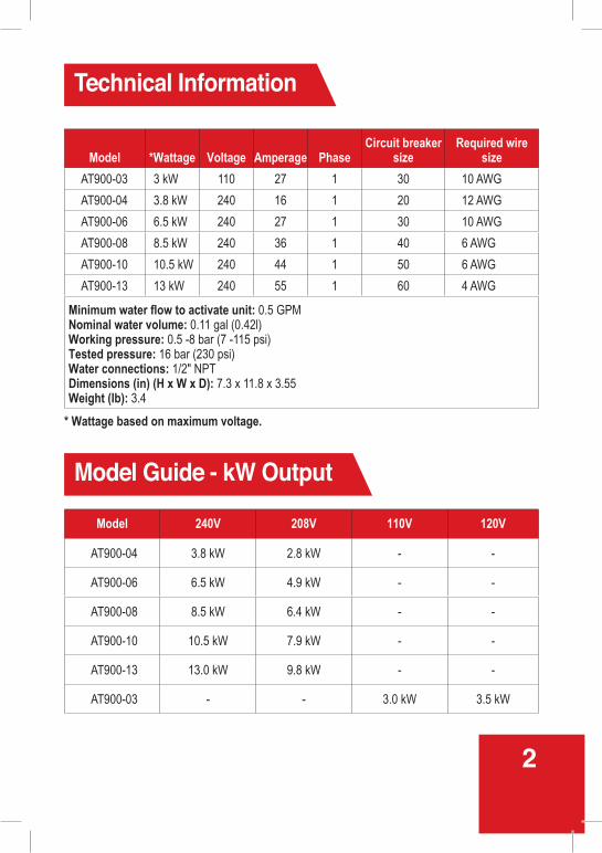
Technical Information
Model Guide - kW Output
2
Model *Wattage Voltage Amperage PhaseCircuit breaker
sizeRequired wire
size
AT900-03 3 kW 110 27 1 30 10 AWG
AT900-04 3.8 kW 240 16 1 20 12 AWG
AT900-06 6.5 kW 240 27 1 30 10 AWG
AT900-08 8.5 kW 240 36 1 40 6 AWG
AT900-10 10.5 kW 240 44 1 50 6 AWG
AT900-13 13 kW 240 55 1 60 4 AWG
Minimum water flow to activate unit: 0.5 GPMNominal water volume: 0.11 gal (0.42l) Working pressure: 0.5 -8 bar (7 -115 psi)Tested pressure: 16 bar (230 psi)Water connections: 1/2" NPTDimensions (in) (H x W x D): 7.3 x 11.8 x 3.55Weight (Ib): 3.4
Model 240V 208V 110V 120V
AT900-04 3.8 kW 2.8 kW - -
AT900-06 6.5 kW 4.9 kW - -
AT900-08 8.5 kW 6.4 kW - -
AT900-10 10.5 kW 7.9 kW - -
AT900-13 13.0 kW 9.8 kW - -
AT900-03 - - 3.0 kW 3.5 kW
* Wattage based on maximum voltage.

01
05
06
02
04
03Remove the appliance covers (Figure 2).
Connect the Pressure Relief Device (PRD) to the unit (Fig1)Note: IMPORTANT – do not discard this step. A PRD must be installed.
Connect the water inlet hose to the entry point of the heater (left side inlet), and connect the outlet hose to the water outlet. Use a hose that can withstand a minimum pressure of 4 bars. Using any other type of hose will cause damage (Figure 5).
Residential plumbing systems with unstable pressure or pressure above 5 bar require the application of a pressure stabilizer valve, set to 4 – 5 bars.
Do not install the appliance with water inlets and outlets at the top (Figure 6)
Mount unit to wall with 4 screws at the marked points (Figure 4)
The appliance must be mounted horizontally, with water inlets and outlets at the bottom (Figure 5)
1. Mount ground plate to wall.
2. Pull wires through.3. Cut out hole in back
of unit (Right/Left back) and pass wires through
(Figure 3)
Assembly Instructions
3

4
2
3 4
65
G = Green or YellowN = WhiteL1/L2 = Black
1 Rubber
Cold Hot
PRD
*
L1 L2 N **
*3a)3kW
*3b)3.5-8.5kW
*3c)8.6-13kW
Note: Neutral (N) does not need to be connected.
L1
L1
L2N
(L2)
L1G
G
N
N L1
L1G
GN L1
L2

5
07
1009
13
08
It is recommended that the appliance electrical connections be tested once a year by a qualified technician.
Run the water flow for one minute to check for leakage before connecting to power.
Reattach the front cover of the heater and secure it with 4 screws and then slide the bottom gray cover
Connect the power cable to the terminal block.Caution: The heater must be grounded.Reference figure *3 on page 4 and Electrical diagram on page 6
When installed outdoors, the heater must be placed in sealed waterproof electrical box.
Make sure that the appliance is filled with water before connecting power. (Repeat step 7)
11 12 Do not install the heater where it may be subject to direct sunlight.

6
Electrical Diagram
1. Terminal block 2. Thermal cut-out with reset3. Thermal cut-out 4. Relay5. Light6. Switch 0- Off (Option) 1- Low7. Heating element8. Read sensor
1. Terminal block 2. Thermal cut-out with reset3. Thermal Cut out4. Relay5. Switch 0- Off 1- Low 2- Medium 3- High6. Heating element7. Read sensor8. EARTH(G) Connection in
the heating canister
411 53 6
78
L1
L2(*N)
E(G)
L
N
E(G)
11
L
E(G)
N
L1
E(G)
L2(*N)
1. Terminal block 2. Thermostat with reset3. Thermostat4. Switches with lights5. Relay6. Heating elements7. Read sensor8. EARTH(G) Connection in
the heating canister
L1
L2(*N)
E(G)
5 641 2 7
3
L
N
E (G)
81
8.6kW-10.5kW (240V)
10.6kW-13kW (240V)
1. 3-3.4kW (110V) - Install Line 1 (L1), E(G)-Ground, N (Neutral)2. 3.5-8.5kW (240V) - Install Line 1 (L1), E(G)-Ground, Line 2 (L2)
L1/L2 = Line1/Line2 (Black or Red)E(G) = Ground (Green/Yellow)*N = Neutral (White or Silver)*Neutral acts as Line 2 (L2) for 220V/240V*Neutral does not have to be connected for 3.5kW-13kW

Operation Guide
Troubleshooting
7
MODEL kW kW kW
AT900-03 1 2 3
AT900-04 1.6 2.2 3.8
AT900-06 3 3.5 6.5
AT900-08 3.8 4.7 8.5
AT900-10 5.25 5.25 10.5
AT900-13 4.5 8.5 13
PROBLEM ISSUE POSSIBLE CAUSE SOLUTION
Water not hot enough.
Too much water flowing through the heater.
Reduction in the ambient temperature.
Water Pressure below of 0.5 bar (7 psi).
Electrical Malfunction.
Reduce the flow rate of the water via the outlet tap.
Switch to higher temperature setting.
Check if the main water line stop valve is fully open and that there are no other restrictions in the water supply line.
Have the Heater unit check by a qualified eIectrician or contact your local authorized distributor.
Low Medium High

Troubleshooting
8
PROBLEM ISSUE POSSIBLE CAUSE SOLUTION
Water too hot. Not enough water flowing through the heater.
Increase in the ambient temperature.
Increase the flow rate via the outlet tap.
Switch to lower temperature setting.
Heater shut off during use.
Interruption of main electrical supply.
Check incoming power supply, MCB, switches and supply cabling.
If problem persists, call your local authorized distributor for assistance.
Water ceases to flow.
Blockage of your hand held shower head.
No water supply.
Clean or replace your hand held shower head. Check to see that your shower head hose is not twisted or blocked. It is necessary for the hose to have a free passage of water.
Check if the main water line stop valve is fully open and that there are no other restrictions in the water supply line.
Water temperature varies from hot to cold during use.
Water pressure has dropped below min. level.
Increase hot water supply.
No hot water/Unit is not working.
No electrical power.
Low flow rate 0.5 bar (7 psi).
Check the circuit breaker and check voltage at the wiring block.
Clean filter screen:1. Turn circuit breaker off.2. Open the valve to release pressure
from the unit.3. Turn circuit breaker on.
If you have an issue and need further assistance,please call: 1-888-783-6082

3. Cold water inlet
2. PRD
5. Hot water outlet (to be connected to the main hot water pipe)
1. Switches
9
Parts

10

LIMITED WARRANTYAtmor warrants to the original owner that our instant water heaters will be free from defects
in workmanship and material for a period of TWO YEARS from the date of purchase, and
free from leakage for a period of SEVEN YEARS from the date of purchase. Should any
part(s) prove to be defective during this period, Atmor will be responsible for replacement
of the defective part(s) only. Atmor is not responsible for labor charges or any incidental or
consequential expenses.
Should the owner wish to return the water heater for repair, the owner must first secure a
written authorization from Atmor. The owner shall be required to show proof of purchase date
and to pay all transportation costs to return the defective part(s) or water heater for repair or
replacement. Warranty is void if: (i) water heater has been installed or used improperly; (ii)
design has been altered in any way; (iii) water heater has been installed and/or serviced by
someone other than a licensed electrician ; (iv) or if the water heater has been installed or used
in contradiction to installation instructions, applicable laws and/or ordinances.
Distributed by:
PARAGON GROUP USA LLC15 Engle Street, 3rd Floor
Englewood, NJ 07631
1-888-783-6082
P.N
. 115
045C