hotwire dsl routers - dzs
TRANSCRIPT
Hotwire® DSL Routers
Models 6301, 6302, 6341, 6342,6351, and 6371
User’s GuideDocument No. 6300-A2-GB20-10
November 2003
A November 2003 6300-A2-GB20-10
Copyright © 2003 Paradyne Corporation.All rights reserved.Printed in U.S.A.
Notice
This publication is protected by federal copyright law. No part of this publication may be copied or distributed, transmitted, transcribed, stored in a retrieval system, or translated into any human or computer language in any form or by any means, electronic, mechanical, magnetic, manual or otherwise, or disclosed to third parties without the express written permission of Paradyne Corporation, 8545 126th Ave. N., Largo, FL 33773.
Paradyne Corporation makes no representation or warranties with respect to the contents hereof and specifically disclaims any implied warranties of merchantability or fitness for a particular purpose. Further, Paradyne Corporation reserves the right to revise this publication and to make changes from time to time in the contents hereof without obligation of Paradyne Corporation to notify any person of such revision or changes.
Changes and enhancements to the product and to the information herein will be documented and issued as a new release to this manual.
Warranty, Sales, Service, and Training Information
Contact your local sales representative, service representative, or distributor directly for any help needed. For additional information concerning warranty, sales, service, repair, installation, documentation, training, distributor locations, or Paradyne worldwide office locations, use one of the following methods:
� Internet: Visit the Paradyne World Wide Web site at www.paradyne.com. (Be sure to register your warranty at www.paradyne.com/warranty.)
� Telephone: Call our automated system to receive current information by fax or to speak with a company representative.
— Within the U.S.A., call 1-800-870-2221
— Outside the U.S.A., call 1-727-530-2340
Document Feedback
We welcome your comments and suggestions about this document. Please mail them to Technical Publications, Paradyne Corporation, 8545 126th Ave. N., Largo, FL 33773, or send e-mail to [email protected]. Include the number and title of this document in your correspondence. Please include your name and phone number if you are willing to provide additional clarification.
Trademarks
ACCULINK, COMSPHERE, ETC, EtherLoop, FrameSaver, GranDSLAM, Hotwire, the Hotwire logo, Jetstream, MVL, NextEDGE, OpenLane, Paradyne, the Paradyne logo, Paradyne Credit Corp., the Paradyne Credit Corp. logo, Performance Wizard, StormPort, and TruePut are all registered trademarks of Paradyne Corporation. ADSL/R, BitStorm, Connect to Success, GrandVIEW, Hotwire Connected, iMarc, JetFusion, JetVision, MicroBurst, PacketSurfer, ReachDSL, Spectrum Manager, StormTracker, and TriplePlay are trademarks of Paradyne Corporation. All other products and services mentioned herein are the trademarks, service marks, registered trademarks, or registered service marks of their respective owners.
6300-A2-GB20-10 November 2003 i
Contents
About This Guide
� Document Purpose and Intended Audience . . . . . . . . . . . . . . . . . . . . vii
� New Features for this Release. . . . . . . . . . . . . . . . . . . . . . . . . . . . . . . viii
� Document Summary . . . . . . . . . . . . . . . . . . . . . . . . . . . . . . . . . . . . . . ix
� Product-Related Documents . . . . . . . . . . . . . . . . . . . . . . . . . . . . . . . . x
� Document Conventions . . . . . . . . . . . . . . . . . . . . . . . . . . . . . . . . . . . . xi
1 Introduction to Hotwire DSL Routers
� What is a Hotwire DSL Router? . . . . . . . . . . . . . . . . . . . . . . . . . . . . . . 1-1
DSL Technologies Supported . . . . . . . . . . . . . . . . . . . . . . . . . . . . 1-1
� Typical DSL Router System . . . . . . . . . . . . . . . . . . . . . . . . . . . . . . . . . 1-2
� Hotwire DSL Router Features . . . . . . . . . . . . . . . . . . . . . . . . . . . . . . . 1-3
� Service Subscriber . . . . . . . . . . . . . . . . . . . . . . . . . . . . . . . . . . . . . . . . 1-4
2 Accessing the DSL Router
� Access Control to the DSL Router . . . . . . . . . . . . . . . . . . . . . . . . . . . . 2-1
Levels of Access . . . . . . . . . . . . . . . . . . . . . . . . . . . . . . . . . . . . . . 2-1
� Local Console Access . . . . . . . . . . . . . . . . . . . . . . . . . . . . . . . . . . . . . 2-2
Changing Access Session Levels . . . . . . . . . . . . . . . . . . . . . . . . . 2-2
Setting Up the New User’s Login . . . . . . . . . . . . . . . . . . . . . . . . . . 2-3
� Telnet Access. . . . . . . . . . . . . . . . . . . . . . . . . . . . . . . . . . . . . . . . . . . . 2-4
� Determining the Current Access Level. . . . . . . . . . . . . . . . . . . . . . . . . 2-5
Determining the Available Commands . . . . . . . . . . . . . . . . . . . . . 2-5
� Using the List Command . . . . . . . . . . . . . . . . . . . . . . . . . . . . . . . . . . . 2-6
� Changing the System Identity . . . . . . . . . . . . . . . . . . . . . . . . . . . . . . . 2-6
� Exiting from the System . . . . . . . . . . . . . . . . . . . . . . . . . . . . . . . . . . . . 2-7
Manually Logging Out . . . . . . . . . . . . . . . . . . . . . . . . . . . . . . . . . . 2-7
Automatically Logging Out. . . . . . . . . . . . . . . . . . . . . . . . . . . . . . . 2-8
3 Configuring the DSL Router� DSL Router Configuration Overview . . . . . . . . . . . . . . . . . . . . . . . . . . 3-1
� The DSL Router’s Interfaces . . . . . . . . . . . . . . . . . . . . . . . . . . . . . . . . 3-1
Interface Identifiers . . . . . . . . . . . . . . . . . . . . . . . . . . . . . . . . . . . . 3-2
Contents
ii November 2003 6300-A2-GB20-10
� Service Domain IP Address Assignments. . . . . . . . . . . . . . . . . . . . . . 3-2
Numbered DSL or Ethernet Interface . . . . . . . . . . . . . . . . . . . . . . 3-3
Unnumbered DSL Interface . . . . . . . . . . . . . . . . . . . . . . . . . . . . . . 3-3
� IP Routing . . . . . . . . . . . . . . . . . . . . . . . . . . . . . . . . . . . . . . . . . . . . . . 3-4
� IP Options Processing . . . . . . . . . . . . . . . . . . . . . . . . . . . . . . . . . . . . . 3-4
� Network Considerations . . . . . . . . . . . . . . . . . . . . . . . . . . . . . . . . . . . . 3-5
� Address Resolution Protocol (ARP) . . . . . . . . . . . . . . . . . . . . . . . . . . . 3-5
� Proxy ARP . . . . . . . . . . . . . . . . . . . . . . . . . . . . . . . . . . . . . . . . . . . . . . 3-6
� Network Address Translation (NAT) . . . . . . . . . . . . . . . . . . . . . . . . . . 3-7
Basic NAT . . . . . . . . . . . . . . . . . . . . . . . . . . . . . . . . . . . . . . . . . . . 3-7
Network Address Port Translation (NAPT/PAT) . . . . . . . . . . . . . . 3-7
Simultaneous Basic NAT and NAPT . . . . . . . . . . . . . . . . . . . . . . . 3-8
Applications Supported by NAT. . . . . . . . . . . . . . . . . . . . . . . . . . . 3-8
� Dynamic Host Configuration Protocol (DHCP) Server . . . . . . . . . . . . . 3-9
� DHCP Relay Agent . . . . . . . . . . . . . . . . . . . . . . . . . . . . . . . . . . . . . . . 3-10
� Security . . . . . . . . . . . . . . . . . . . . . . . . . . . . . . . . . . . . . . . . . . . . . . . . 3-11
IP Protocol Type Filtering . . . . . . . . . . . . . . . . . . . . . . . . . . . . . . . 3-11
Ethernet Type Filtering . . . . . . . . . . . . . . . . . . . . . . . . . . . . . . . . . 3-12
Land Bug/Smurf Attack Prevention . . . . . . . . . . . . . . . . . . . . . . . . 3-12
� Routed vs. Bridged PDUs . . . . . . . . . . . . . . . . . . . . . . . . . . . . . . . . . . 3-13
� PPPoE Client Support . . . . . . . . . . . . . . . . . . . . . . . . . . . . . . . . . . . . . 3-14
4 DSL Router Configuration Examples
� Configuration Examples . . . . . . . . . . . . . . . . . . . . . . . . . . . . . . . . . . . . 4-1
Basic Bridging Configuration Example . . . . . . . . . . . . . . . . . . . . . 4-2
Basic Routing Configuration Example . . . . . . . . . . . . . . . . . . . . . . 4-3
Basic NAT Configuration Example . . . . . . . . . . . . . . . . . . . . . . . . 4-4
NAPT Configuration Example . . . . . . . . . . . . . . . . . . . . . . . . . . . . 4-6
Simultaneous Basic NAT and NAPT Configuration Example . . . . 4-8
Unnumbered DSL Interface with Proxy ARP Configuration Example 4-10
DHCP Relay with Proxy ARP Configuration Example . . . . . . . . . . 4-11
DHCP Server with Basic NAT Configuration Example . . . . . . . . . 4-12
PPPoE Client with NAPT and DHCP Server Configuration Example 4-13
Downstream Router Configuration Example . . . . . . . . . . . . . . . . . 4-14
IP Passthrough Configuration Example. . . . . . . . . . . . . . . . . . . . . 4-15
5 Monitoring the DSL Router
� Monitoring the Router. . . . . . . . . . . . . . . . . . . . . . . . . . . . . . . . . . . . . . 5-1
Contents
6300-A2-GB20-10 November 2003 iii
� LED Status . . . . . . . . . . . . . . . . . . . . . . . . . . . . . . . . . . . . . . . . . . . . . . 5-2
� Interface Status . . . . . . . . . . . . . . . . . . . . . . . . . . . . . . . . . . . . . . . . . . 5-3
� Performance Statistics . . . . . . . . . . . . . . . . . . . . . . . . . . . . . . . . . . . . . 5-3
Clearing Statistics . . . . . . . . . . . . . . . . . . . . . . . . . . . . . . . . . . . . . 5-3
Reasons for Discarded Data . . . . . . . . . . . . . . . . . . . . . . . . . . . . . 5-4
6 Diagnostics and Troubleshooting
� Diagnostics and Troubleshooting Overview. . . . . . . . . . . . . . . . . . . . . 6-1
� Device Restart . . . . . . . . . . . . . . . . . . . . . . . . . . . . . . . . . . . . . . . . . . . 6-1
� Alarms Inquiry . . . . . . . . . . . . . . . . . . . . . . . . . . . . . . . . . . . . . . . . . . . 6-1
� System Log . . . . . . . . . . . . . . . . . . . . . . . . . . . . . . . . . . . . . . . . . . . . . 6-2
SYSLOG Events . . . . . . . . . . . . . . . . . . . . . . . . . . . . . . . . . . . . . . 6-4
SYSLOG Message Display . . . . . . . . . . . . . . . . . . . . . . . . . . . . . . 6-5
� Ping . . . . . . . . . . . . . . . . . . . . . . . . . . . . . . . . . . . . . . . . . . . . . . . . . . . 6-5
Ping Test Results. . . . . . . . . . . . . . . . . . . . . . . . . . . . . . . . . . . . . . 6-6
� TraceRoute . . . . . . . . . . . . . . . . . . . . . . . . . . . . . . . . . . . . . . . . . . . . . 6-7
TraceRoute Test Results . . . . . . . . . . . . . . . . . . . . . . . . . . . . . . . . 6-8
A Command Line Interface
� Command Line Interface Capability . . . . . . . . . . . . . . . . . . . . . . . . . . . A-1
Navigating the Router’s CLI. . . . . . . . . . . . . . . . . . . . . . . . . . . . . . A-2
Command Recall . . . . . . . . . . . . . . . . . . . . . . . . . . . . . . . . . . . . . . A-2
Syntax Conventions. . . . . . . . . . . . . . . . . . . . . . . . . . . . . . . . . . . . A-2
� CLI Commands . . . . . . . . . . . . . . . . . . . . . . . . . . . . . . . . . . . . . . . . . . A-3
Configuration Commands . . . . . . . . . . . . . . . . . . . . . . . . . . . . . . . A-4
RFC 1483 Encapsulation Command . . . . . . . . . . . . . . . . . . . . . . . A-5
Ethernet Frame Format Command . . . . . . . . . . . . . . . . . . . . . . . . A-5
Interface and Service Domain IP Address Commands . . . . . . . . . A-6
IP Routing Commands. . . . . . . . . . . . . . . . . . . . . . . . . . . . . . . . . . A-7
Bridge Commands . . . . . . . . . . . . . . . . . . . . . . . . . . . . . . . . . . . . . A-8
ARP Commands . . . . . . . . . . . . . . . . . . . . . . . . . . . . . . . . . . . . . . A-9
Proxy ARP Command . . . . . . . . . . . . . . . . . . . . . . . . . . . . . . . . . . A-10
NAT Commands . . . . . . . . . . . . . . . . . . . . . . . . . . . . . . . . . . . . . . A-11
DHCP Server Commands . . . . . . . . . . . . . . . . . . . . . . . . . . . . . . . A-14
DHCP Relay Agent Commands. . . . . . . . . . . . . . . . . . . . . . . . . . . A-16
IP Packet Processing Commands . . . . . . . . . . . . . . . . . . . . . . . . . A-17
PPPoE Client Commands . . . . . . . . . . . . . . . . . . . . . . . . . . . . . . . A-18
Telnet Commands . . . . . . . . . . . . . . . . . . . . . . . . . . . . . . . . . . . . . A-21
Traps Command . . . . . . . . . . . . . . . . . . . . . . . . . . . . . . . . . . . . . . A-23
Clearing Statistics Command . . . . . . . . . . . . . . . . . . . . . . . . . . . . A-23
Contents
iv November 2003 6300-A2-GB20-10
Show Commands . . . . . . . . . . . . . . . . . . . . . . . . . . . . . . . . . . . . . A-24
B Configuration Defaults and Command Line Shortcuts� Configuration Default Settings . . . . . . . . . . . . . . . . . . . . . . . . . . . . . . . B-1
� Command Line Shortcuts. . . . . . . . . . . . . . . . . . . . . . . . . . . . . . . . . . . B-3
C Traps and MIBs
� SNMP Overview. . . . . . . . . . . . . . . . . . . . . . . . . . . . . . . . . . . . . . . . . . C-1
� Traps Overview . . . . . . . . . . . . . . . . . . . . . . . . . . . . . . . . . . . . . . . . . . C-1
DSL Router Traps . . . . . . . . . . . . . . . . . . . . . . . . . . . . . . . . . . . . . C-2
� MIBs Overview . . . . . . . . . . . . . . . . . . . . . . . . . . . . . . . . . . . . . . . . . . . C-3
� Standard MIBs . . . . . . . . . . . . . . . . . . . . . . . . . . . . . . . . . . . . . . . . . . . C-3
MIB II (RFC 1213) . . . . . . . . . . . . . . . . . . . . . . . . . . . . . . . . . . . . . C-3
System Group . . . . . . . . . . . . . . . . . . . . . . . . . . . . . . . . . . . . . . . . C-4
Interfaces Group (RFC 1573) . . . . . . . . . . . . . . . . . . . . . . . . . . . . C-5
Extension to Interfaces Table (RFC 1573) . . . . . . . . . . . . . . . . . . C-7
IP Group (RFC 1213). . . . . . . . . . . . . . . . . . . . . . . . . . . . . . . . . . . C-8
IP CIDR Route Group (RFC 2096) . . . . . . . . . . . . . . . . . . . . . . . . C-9
Transmission Group . . . . . . . . . . . . . . . . . . . . . . . . . . . . . . . . . . . C-10
SNMP Group . . . . . . . . . . . . . . . . . . . . . . . . . . . . . . . . . . . . . . . . . C-10
Ethernet-Like MIB (RFC 2665) . . . . . . . . . . . . . . . . . . . . . . . . . . . C-11
� Paradyne Enterprise MIBs . . . . . . . . . . . . . . . . . . . . . . . . . . . . . . . . . . C-11
Device Control MIB . . . . . . . . . . . . . . . . . . . . . . . . . . . . . . . . . . . . C-12
Device Diagnostics MIB. . . . . . . . . . . . . . . . . . . . . . . . . . . . . . . . . C-13
Health and Status MIB. . . . . . . . . . . . . . . . . . . . . . . . . . . . . . . . . . C-16
Configuration MIB . . . . . . . . . . . . . . . . . . . . . . . . . . . . . . . . . . . . . C-17
Interface Configuration MIB . . . . . . . . . . . . . . . . . . . . . . . . . . . . . . C-18
ARP MIB . . . . . . . . . . . . . . . . . . . . . . . . . . . . . . . . . . . . . . . . . . . . C-18
NAT MIB . . . . . . . . . . . . . . . . . . . . . . . . . . . . . . . . . . . . . . . . . . . . C-18
DHCP MIB . . . . . . . . . . . . . . . . . . . . . . . . . . . . . . . . . . . . . . . . . . . C-19
DSL Endpoint MIB . . . . . . . . . . . . . . . . . . . . . . . . . . . . . . . . . . . . . C-20
SYSLOG MIB. . . . . . . . . . . . . . . . . . . . . . . . . . . . . . . . . . . . . . . . . C-20
Interface Configuration MIB . . . . . . . . . . . . . . . . . . . . . . . . . . . . . . C-20
D DSL Router Terminal Emulation� DSL Router Terminal Emulation . . . . . . . . . . . . . . . . . . . . . . . . . . . . . D-1
Accessing the List Command Output . . . . . . . . . . . . . . . . . . . . . . D-1
Terminal Emulation Programs . . . . . . . . . . . . . . . . . . . . . . . . . . . . D-2

Contents
6300-A2-GB20-10 November 2003 v
E Firmware Upgrade
� Overview . . . . . . . . . . . . . . . . . . . . . . . . . . . . . . . . . . . . . . . . . . . . . . . E-1
� Firmware Upgrade Commands . . . . . . . . . . . . . . . . . . . . . . . . . . . . . . E-1
� Firmware Upgrade Procedures . . . . . . . . . . . . . . . . . . . . . . . . . . . . . . E-2
Index

Contents
vi November 2003 6300-A2-GB20-10
6300-A2-GB20-10 November 2003 vii
About This Guide
Document Purpose and Intended Audience
This guide describes how to configure and operate Hotwire DSL routers. It addresses the following models:
� Hotwire 6301/6302 IDSL Router
� Hotwire 6341/6342 Symmetric DSL Router
� Hotwire 6351 ReachDSL Router
� Hotwire 6371 RADSL Router
This document is intended for administrators and operators who maintain the endpoints at customer premises. A basic understanding of internetworking protocols and their features is assumed. Specifically, you should have familiarity with the following internetworking concepts:
� TCP/IP applications
� IP and subnet addressing
� IP routing
� Bridging
It is also assumed that you have already installed a Hotwire DSL Router. If not, refer to Product-Related Documents for installation documents.
About This Guide
viii November 2003 6300-A2-GB20-10
New Features for this Release
This version of the Hotwire DSL Routers User’s Guide documents firmware release 4.4, which adds the following new features for the Hotwire 6351 ReachDSL Router:
� IP passthrough. This feature allows the router to pass through or share its public IP address with a single LAN device. The DSL router establishes a PPPoE and PPP session with the Network Access Server (NAS). The public IP address is negotiated via IPCP, installed on the router’s DSL interface, and served to the passthrough device via DHCP.
� Automatic configuration of options provided by the DHCP server to its clients. This feature is available when PPPoE is enabled and is the default unless explicitly refused by the user. This allows the DHCP Server option configuration items to be set automatically with values negotiated during the network layer protocol phase of PPP (IPCP).
� Secondary DNS server. The DHCP server can specify a secondary DNS server in its offer to a client.
� No router option required. Configuration of the DHCP Server feature no longer requires that a value for the Router option be specified.
About This Guide
6300-A2-GB20-10 November 2003 ix
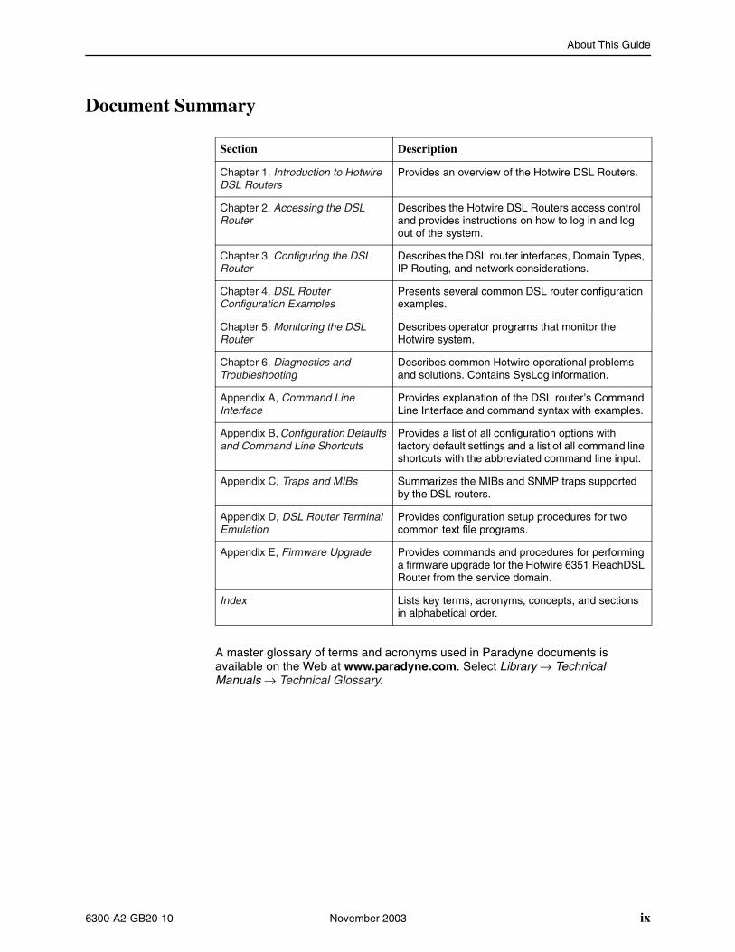
Document Summary
A master glossary of terms and acronyms used in Paradyne documents is available on the Web at www.paradyne.com. Select Library → Technical Manuals → Technical Glossary.
Section Description
Chapter 1, Introduction to Hotwire DSL Routers
Provides an overview of the Hotwire DSL Routers.
Chapter 2, Accessing the DSL Router
Describes the Hotwire DSL Routers access control and provides instructions on how to log in and log out of the system.
Chapter 3, Configuring the DSL Router
Describes the DSL router interfaces, Domain Types, IP Routing, and network considerations.
Chapter 4, DSL Router Configuration Examples
Presents several common DSL router configuration examples.
Chapter 5, Monitoring the DSL Router
Describes operator programs that monitor the Hotwire system.
Chapter 6, Diagnostics and Troubleshooting
Describes common Hotwire operational problems and solutions. Contains SysLog information.
Appendix A, Command Line Interface
Provides explanation of the DSL router’s Command Line Interface and command syntax with examples.
Appendix B, Configuration Defaults and Command Line Shortcuts
Provides a list of all configuration options with factory default settings and a list of all command line shortcuts with the abbreviated command line input.
Appendix C, Traps and MIBs Summarizes the MIBs and SNMP traps supported by the DSL routers.
Appendix D, DSL Router Terminal Emulation
Provides configuration setup procedures for two common text file programs.
Appendix E, Firmware Upgrade Provides commands and procedures for performing a firmware upgrade for the Hotwire 6351 ReachDSL Router from the service domain.
Index Lists key terms, acronyms, concepts, and sections in alphabetical order.
About This Guide
x November 2003 6300-A2-GB20-10
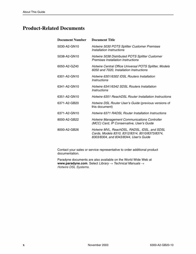
Product-Related Documents
Contact your sales or service representative to order additional product documentation.
Paradyne documents are also available on the World Wide Web at www.paradyne.com. Select Library → Technical Manuals → Hotwire DSL Systems.
Document Number Document Title
5030-A2-GN10 Hotwire 5030 POTS Splitter Customer Premises Installation Instructions
5038-A2-GN10 Hotwire 5038 Distributed POTS Splitter Customer Premises Installation Instructions
6050-A2-GZ40 Hotwire Central Office Universal POTS Splitter, Models 6050 and 7020, Installation Instructions
6301-A2-GN10 Hotwire 6301/6302 IDSL Routers Installation Instructions
6341-A2-GN10 Hotwire 6341/6342 SDSL Routers Installation Instructions
6351-A2-GN10 Hotwire 6351 ReachDSL Router Installation Instructions
6371-A2-GB20 Hotwire DSL Router User’s Guide (previous versions of this document)
6371-A2-GN10 Hotwire 6371 RADSL Router Installation Instructions
8000-A2-GB22 Hotwire Management Communications Controller (MCC) Card, IP Conservative, User's Guide
8000-A2-GB26 Hotwire MVL, ReachDSL, RADSL, IDSL, and SDSL Cards, Models 8310, 8312/8314, 8510/8373/8374, 8303/8304, and 8343/8344, User's Guide
About This Guide
6300-A2-GB20-10 November 2003 xi
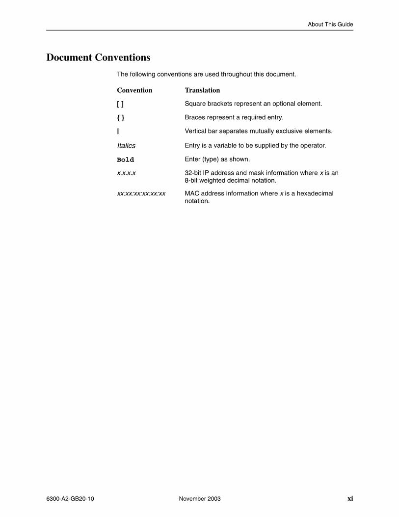
Document Conventions
The following conventions are used throughout this document.
Convention Translation
[ ] Square brackets represent an optional element.
{ } Braces represent a required entry.
| Vertical bar separates mutually exclusive elements.
Italics Entry is a variable to be supplied by the operator.
Bold Enter (type) as shown.
x.x.x.x 32-bit IP address and mask information where x is an 8-bit weighted decimal notation.
xx:xx:xx:xx:xx:xx MAC address information where x is a hexadecimal notation.

About This Guide
xii November 2003 6300-A2-GB20-10
6300-A2-GB20-10 November 2003 1-1
1Introduction to Hotwire DSL Routers
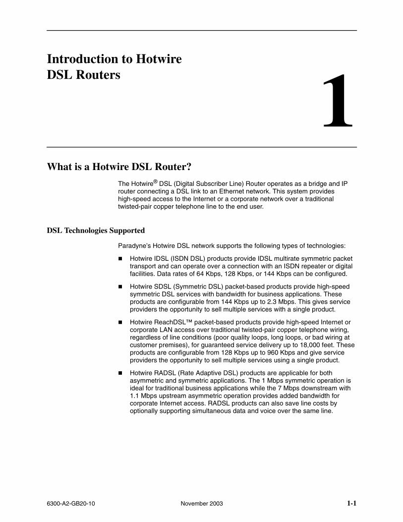
What is a Hotwire DSL Router?
The Hotwire® DSL (Digital Subscriber Line) Router operates as a bridge and IP router connecting a DSL link to an Ethernet network. This system provides high-speed access to the Internet or a corporate network over a traditional twisted-pair copper telephone line to the end user.
DSL Technologies Supported
Paradyne’s Hotwire DSL network supports the following types of technologies:
� Hotwire IDSL (ISDN DSL) products provide IDSL multirate symmetric packet transport and can operate over a connection with an ISDN repeater or digital facilities. Data rates of 64 Kbps, 128 Kbps, or 144 Kbps can be configured.
� Hotwire SDSL (Symmetric DSL) packet-based products provide high-speed symmetric DSL services with bandwidth for business applications. These products are configurable from 144 Kbps up to 2.3 Mbps. This gives service providers the opportunity to sell multiple services with a single product.
� Hotwire ReachDSL™ packet-based products provide high-speed Internet or corporate LAN access over traditional twisted-pair copper telephone wiring, regardless of line conditions (poor quality loops, long loops, or bad wiring at customer premises), for guaranteed service delivery up to 18,000 feet. These products are configurable from 128 Kbps up to 960 Kbps and give service providers the opportunity to sell multiple services using a single product.
� Hotwire RADSL (Rate Adaptive DSL) products are applicable for both asymmetric and symmetric applications. The 1 Mbps symmetric operation is ideal for traditional business applications while the 7 Mbps downstream with 1.1 Mbps upstream asymmetric operation provides added bandwidth for corporate Internet access. RADSL products can also save line costs by optionally supporting simultaneous data and voice over the same line.
1. Introduction to Hotwire DSL Routers
1-2 November 2003 6300-A2-GB20-10
Typical DSL Router System
DSL is a local loop technology that uses standard twisted-pair copper wire to support high-speed access over a single pair of twisted copper wires. DSL applications are point-to-point, requiring DSL devices at central and end-user sites.
Hotwire DSL routers interoperate with the following types of Hotwire DSL line cards, at the DSLAM (Digital Subscriber Line Access Multiplexer) or GranDSLAM chassis, to deliver applications at high speeds, supporting packet services over a DSL link:
� Hotwire 8303 or 8304 IDSL Cards interoperate with two Hotwire IDSL Routers:
— Hotwire 6301 IDSL Router with one Ethernet port
— Hotwire 6302 IDSL Router with a 4-port Ethernet hub
� Hotwire 8343 or 8344 SDSL Cards interoperate with two Hotwire Symmetric DSL Routers:
— Hotwire 6341 SDSL Router with one Ethernet port
— Hotwire 6342 SDSL Router with a 4-port Ethernet hub
� Hotwire 8312 or 8314 ReachDSL Cards interoperate with the Hotwire 6351 ReachDSL Router with one Ethernet port
� Hotwire 8510, 8373, and 8374 RADSL Cards interoperate with the Hotwire 6371 RADSL Router with one Ethernet port
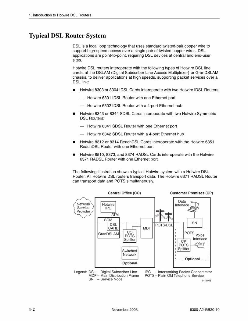
The following illustration shows a typical Hotwire system with a Hotwire DSL Router. All Hotwire DSL routers transport data. The Hotwire 6371 RADSL Router can transport data and POTS simultaneously.
Legend: DSL – Digital Subscriber Line IPC – Interworking Packet ConcentratorMDF – Main Distribution Frame POTS – Plain Old Telephone ServiceSN – Service Node
GranDSLAM
Central Office (CO)
01-16968
Customer Premises (CP)
ATM
SN
CPPOTSSplitter
COPOTSSplitter
MDFPOTS/DSL
HotwireIPC
VoiceInterface
DataInterface
POTS
NetworkServiceProvider
OptionalOptional
SwitchedNetwork
DSLCARD
SCM
1. Introduction to Hotwire DSL Routers
6300-A2-GB20-10 November 2003 1-3
Hotwire DSL Router Features
Hotwire DSL routers contain the following features.
� IP routing with:
— NAT (Network Address Translation)
— NAPT (Network Address Port Translation), also called PAT (Port Address Translation)
— Simultaneous Basic NAT (for several fixed servers) and NAPT (on the rest of the PCs on the LAN)
— DHCP Server (Dynamic Host Configuration Protocol) and DHCP Relay Agent
— A full set of IP filters, two per DSL card (one for upstream and one for downstream traffic), with up to 33 rules per filter
— SNMP Set/Get capability
� Three Configurable Modes of Operation. Supports the following modes of operation:
— IP routing only
— IP routing, and bridging of all other protocols (using VNET mode)
— Bridging all protocols (using VNET mode)
� Protocol Filters. Provides the ability to:
— Filter MAC frames when bridging
— Configure two Ethertype filters via the Hotwire DSL card, one for upstream and one for downstream traffic, with up to 16 filter rules per filter
— Compare the Ethertype in frames to a particular value, or configured set of values, to perform filtering
— Support ICMP (Internet Control Management Protocol) filters for firewalls via the Hotwire DSL card, based on the ICMP message type, to selectively discard some ICMP message types while forwarding others
� High-speed Internet or intranet access.
� Diagnostics. Provides the capability to diagnose device and network problems and perform tests.
� Device and Test Monitoring. Provides the capability of tracking and evaluating the unit’s operation.
� Remote Firmware Download. Provides easy setup and activation of firmware upgrades from a remote location.
� Security. Provides multiple levels of security, which prevents unauthorized access to the DSL router.
1. Introduction to Hotwire DSL Routers
1-4 November 2003 6300-A2-GB20-10
� Console Terminal Interface. Provides an interface for:
— Configuring and managing the DSL router
— Local console access
� Management from an NMS using SNMP.
In addition, the following features are provided for the Hotwire 6351 ReachDSL Router:
� Telnet access to the Command Line Interface (CLI) in the service domain for Network Service Provider (NSP) use.
� TFTP client support for NSP service domain software downloads.
� SYSLOG availability in the service domain.
� Point-to-Point Protocol over Ethernet (PPPoE) client provided as defined in RFC 2516.
� Asymmetric maximum upstream/downstream setting.
Service Subscriber
The Service Subscriber is the user (or set of users) that has contracted to receive networking services (e.g., Internet access, remote LAN access) for the end-user system from an NSP (Network Service Provider). Service subscribers may be:
� Residential users connected to public network services (e.g., the Internet)
� Work-at-home users connected to their corporate intranet LAN
� Commercial users at corporate locations (e.g., branch offices) connected to other corporate locations or connected to public network services
A Hotwire DSL Router must be installed at the customer premises to provide the end user with access to any of the above services.
NOTE:
If you would like more information on DSL-based services, applications, and network deployment, refer to Paradyne’s The DSL Sourcebook. The book may be downloaded or ordered through Paradyne’s World Wide Web site at www.paradyne.com/library.
6300-A2-GB20-10 November 2003 2-1
2Accessing the DSL Router
Access Control to the DSL Router
The Hotwire DSL Router can be managed from an NMS using SNMP or from the Command Line Interface (CLI). There are several methods available for accessing the command line interface:
� Local access at the DSL router through the Console port.
� Access by a Telnet session (controlled through the management interface at the Hotwire chassis).
� For the Hotwire 6351 ReachDSL Router, access by a Telnet session from the service domain.
The Hotwire DSL Router accepts only one login session at a time.
Levels of Access
There are two levels of privileges on the Hotwire DSL system:
� Administrator. The Administrator has two levels of access to the DSL router.
— Administrator, non-configuration mode: Provides read-only capabilities. This is the same level of access as Operator.
— Administrator, configuration mode: Provides complete write access to the DSL router.
� Operator. The Operator has read-only access to display device information with no modification permission and no access to management functions.
Refer to Appendix A, Command Line Interface, for access level details for each command line entry.
For local console access, the Operator and Administrator have the same Login ID, but with different passwords for their access level. For Telnet access through the service domain for the ReachDSL Router, up to four login/password/access level combinations can be configured.
2. Accessing the DSL Router
2-2 November 2003 6300-A2-GB20-10
Local Console Access
Your user account can be configured with one user login name and different passwords for accessing a CLI session. The DSL router ships with the local console enabled. After login, the local console can be disabled.
� To disable with the local console, type:
console disablesaveexit
Press Enter after each command that you type.
Entering console disable results in NO local access to the DSL router. If you attempt to log in, you will receive an error message.
After saving this change and ending the session, there is no local access through the console port. Any access must be through a Telnet session or the NMS.
� To determine via a Telnet session whether a console is enabled, enter:
show console
One of the following messages is returned:
— console enabled – Command line management is available at the console.
— console disabled – No command line management is available at the console.
Changing Access Session Levels
� To change the Administrator access level, enter:
admin enable
This command provides Administrator access privileges. The router responds with a prompt to enter the password for Administrator access.
� To end the Administrator access level, enter:
admin disable
This command ends the Administrator session. No password is needed.
Entering exit has the same result. Refer to Exiting from the System on page 2-7 for further details on ending a session.
� To determine the access level for a session, refer to Determining the Current Access Level on page 2-5.
2. Accessing the DSL Router
6300-A2-GB20-10 November 2003 2-3
Setting Up the New User’s Login
A login prompt appears when the local console connection is first established. When the login prompt appears, a locally connected console defaults to Console Enabled, with Operator access.
Procedure
To access the router’s CLI for the first-time:
1. At the initial Login> prompt, type the default login ID paradyne and press Enter.
2. At the Password> prompt (for Operator), type the default password abc123 and press Enter. The login ID and password are validated together when a login is entered.
3. At the system identity of CUSTOMER> prompt, type admin enable and press Enter.
4. At the Password> prompt (for Administrator), type the default password abc123 and press Enter.
System identity changes to the Administrator display mode of CUSTOMER#>.
5. Type configure terminal and press Enter.
System identity changes to the Administrator configuration mode of CUSTOMER - CONFIG#>.
6. To change or add a new login ID, enter text to replace the default of paradyne:
name your new login ID
NOTE:
Login ID and password are NOT case-sensitive.
7. Enter a new password and specify the level:
password level password
Example: Type password operator 238clrd3 and press Enter.
Both the login ID and password are 1–31 printable alphanumeric ASCII characters, in the ASCII hex range of 0x21–0x7E. No spaces are allowed.
The following table lists invalid characters.
Invalid Characters Value ASCII Hex Translation
# Number sign 0x23
$ Dollar sign 0x24
% Percentage 0x25
& Ampersand 0x26
2. Accessing the DSL Router
2-4 November 2003 6300-A2-GB20-10
8. At the prompt, enter the new Administrator-level password to replace abc123:
password admin new passwordsave
NOTE:
Any input during an Administrator configuration session must be saved while still in configuration mode.
If denied access during a Telnet session, the session stops and an error is logged.
If accessing the router locally and a Telnet session is active, you receive a Local console disabled by conflict message.
Telnet Access
Telnet access through the management interface in the DSLAM is always enabled and defaults to Administrator level. For information on accessing the router through the MCC card in the DSLAM, see the Hotwire Management Communications Controller (MCC) Card, IP Conservative, User’s Guide.
For the Hotwire 6351 ReachDSL Router, Telnet access from the service domain is allowed. Telnet Login and a user name and password should be configured if Telnet access is enabled on the router (the factory default is disable). Up to four access level/login/password combinations can be configured for the service domain from which the ReachDSL Router will accept Telnet connections when the Telnet login feature is enabled.
NOTE:
For network security, Telnet access in the service domain should be disabled after the the initial remote configuration unless a firewall or some other security mechanism is used at the subscriber management system. This ensures that Telnet access to the endpoint is limited to the service provider.
Procedure
To set up Telnet access from the service domain:
1. Type configure terminal and press Enter.
System identity changes to the Administrator configuration mode of CUSTOMER - CONFIG#>.
2. Enable Telnet access form the service domain. Enter:
telnet enable save
2. Accessing the DSL Router
6300-A2-GB20-10 November 2003 2-5
3. To create a login ID and password for a specified access level, enter:
telnet name create level login ID password
Example: Type telnet name create operator 238clrd3 1234 and press Enter.
NOTE:
Login ID and password are NOT case-sensitive. See Step 7 on page 2-3 for list of invalid characters.
4. Enable Telnet login so that the ReachDSL Router will perform login and password validation for the Telnet session connection. Enter:
telnet login enable save
NOTE:
Any input during an Administrator configuration session must be saved while still in configuration mode.
Determining the Current Access Level
The command line prompt displays the access level. The factory default for System identity is CUSTOMER>. You can set your own system identity name to replace CUSTOMER. See the examples below.
Determining the Available Commands
To determine the commands available at the current login access level, enter any of the following:
� help
� ? (question mark)
� the command, without any parameters
If the prompt format appears as . . .
Or, if a System identity of PARADYNE is entered, the prompt displays . . .
Then the DSL router access level is . . .
CUSTOMER> PARADYNE> Operator, display mode
CUSTOMER #> PARADYNE #> Administrator, display mode
CUSTOMER – CONFIG#> PARADYNE – CONFIG#> Administrator, configuration mode
2. Accessing the DSL Router
2-6 November 2003 6300-A2-GB20-10
Using the List Command
The list command displays a sequence of commands in the form of ASCII strings that would have the effect of setting all configuration settings to the current values. Secure information such as passwords and login IDs are not displayed.
To determine the commands available, enter Administrator configuration mode and type either:
� list
Displays the output in on-screen page mode. In on-screen page mode, the user interface displays 23 lines of information. When the 24th line is reached, More... appears. Pressing any key displays the next page.
� list config
Displays the output in scroll mode as a text file. Scroll mode captures and displays all command strings in a text file for use with a terminal emulation program. Refer to Appendix D, DSL Router Terminal Emulation.
Changing the System Identity
The System identity is the same as the MIB entry of sysName. The sysContact and sysLocation MIB entries are not displayed.
Procedure
To change System identity from the factory default of CUSTOMER>:
1. Log in and enter ADMIN-configuration mode.
2. At the CUSTOMER-CONFIG#> prompt, type the new System identity (no spaces allowed) and press Enter. Then type save and press Enter.
system identity new system identity
For example:
system identity PARADYNEsave
In this example, after saving the entry and ending configuration mode, the System identity will display:
PARADYNE#>
Refer to Exiting from the System on page 2-7 to end configuration mode.
2. Accessing the DSL Router
6300-A2-GB20-10 November 2003 2-7
Exiting from the System
You can manually log out of the system, or let the system automatically log you out. The DSL router will log you out immediately if you disconnect the Console cable. Any unsaved configuration input will be lost.
Manually Logging Out
To log out, there are two commands: logout and exit.
Procedure
To log out of a CLI session:
1. At the > prompt, type logout and press Enter.
2. The system ends the session immediately. Any configuration updates must be saved before exiting or the updates will be lost.
Procedure
To exit the DSL router’s current access level:
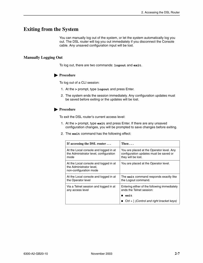
1. At the > prompt, type exit and press Enter. If there are any unsaved configuration changes, you will be prompted to save changes before exiting.
2. The exit command has the following effect:
If accessing the DSL router . . . Then . . .
At the Local console and logged in at the Administrator level, configuration mode
You are placed at the Operator level. Any configuration updates must be saved or they will be lost.
At the Local console and logged in at the Administrator level, non-configuration mode
You are placed at the Operator level.
At the Local console and logged in at the Operator level
The exit command responds exactly like the Logout command.
Via a Telnet session and logged in at any access level
Entering either of the following immediately ends the Telnet session:
� exit
� Ctrl + ] (Control and right bracket keys)
2. Accessing the DSL Router
2-8 November 2003 6300-A2-GB20-10
Automatically Logging Out
The DSL router has an automatic timeout feature that logs you out of the system after five minutes of inactivity. Unsaved configuration input is lost. The default for the autologout command is enable.
When autologout is:
� Enabled, the system inactivity timer is enabled.
� Disabled, the system inactivity timer is disabled.
To log back in, press Enter at the console to display the Login> prompt.
For Telnet access through the service domain for the ReachDSL Router, the Telnet session is automatically closed after a user-configurable number of minutes. The default for the telnet timeout command is 5 (minutes). The telnet timeout command overrides the 5-minute limit enabled by the autologout command. Also, the telnet keep-alive command can be enabled which allows the ReachDSL Router to close the Telnet session if it detects that the service domain Telnet client has crashed and is down or has rebooted.
6300-A2-GB20-10 November 2003 3-1
3Configuring the DSL Router
DSL Router Configuration Overview
Hotwire DSL Routers support various customer premises distribution networks that contain IP forwarding devices or routers, as well as locally attached hosts or subnets. The Hotwire DSL Router’s IP Routing Table contains IP address and subnet mask information.
The DSL router supports Internet Protocol, as specified in RFC 791, and Internet Control Message Protocol (ICMP), as specified in RFCs 792 and 950. It acts as a router (or gateway), as defined in RFC 791. It also acts as a bridge, bridging all traffic in the service domain, or routing IP traffic and bridging all other traffic in the service domain, without affecting traffic in the management domain.
For more information on supported RFCs, refer to Appendix C, Traps and MIBs.
The DSL Router’s Interfaces
Hotwire DSL Routers have two interfaces: the DSL interface and the Ethernet interface.
� DSL Interface
The router’s interface type is determined by its model number:
— Models 6301 and 6302 are Hotwire IDSL Routers.
— Models 6341 and 6342 are Hotwire SDSL Routers.
— Model 6351 is the Hotwire ReachDSL Router.
— Model 6371 is the Hotwire RADSL Router.
The DSL interface has a unique MAC address, assigned before the router is shipped.
3. Configuring the DSL Router
3-2 November 2003 6300-A2-GB20-10
� Ethernet Interface
— The Ethernet interface is a 10/100BaseT interface that automatically negotiates the rate to be used, 10 Mb or 100 Mb. If all Ethernet-attached devices are capable of operating at 100 Mb, the router defaults to 100 Mb. Otherwise, it operates at 10 Mb.
— The interface can be configured for either DIX or IEEE 802.3 frame format. When configured to use IEEE 802.3 format, SNAP encapsulation is used, as specified in RFC 1042.
— The interface has a unique MAC address, assigned before the router is shipped.
— Hotwire 6302 IDSL and 6342 SDSL Routers have a hub configuration (separate pins for input and output) with four Ethernet connectors. The hub acts as a bit-level repeater, with the four Ethernet interfaces logically appearing as one Ethernet communications interface with a single collision domain.
— In router mode, the router only accepts transmissions on the Ethernet interface with the interface’s MAC address, or a broadcast or multicast MAC address.
— In bridge mode, the router accepts all transmissions. This is the default setting.
Interface Identifiers
The following conventions are used for naming router interfaces:
� dsl1 (or d0) – Identifier for the DSL interface.
� eth1 (or e0) – Identifier for the Ethernet interface.
With exception to primary status, an interface cannot be deleted or changed as long as there is a declared route that uses the interface.
Service Domain IP Address Assignments
Hotwire DSL Routers support multiple service domains.
� Service domains are defined by the configured network addresses and subnet masks using the CLI.
� Up to four service domain IP addresses and subnet masks can be assigned to each DSL (dsl1) or Ethernet (eth1) interface.
When a numbered interface is designated as the primary interface, that interface’s IP address is used as the Router ID. If no interface is designated as the primary interface, the last numbered interface that was created becomes the Router ID.
3. Configuring the DSL Router
6300-A2-GB20-10 November 2003 3-3
Numbered DSL or Ethernet Interface
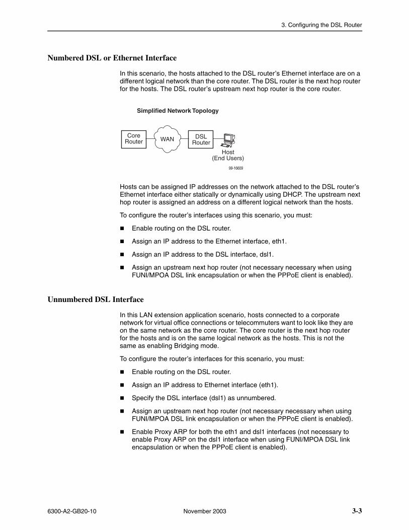
In this scenario, the hosts attached to the DSL router’s Ethernet interface are on a different logical network than the core router. The DSL router is the next hop router for the hosts. The DSL router’s upstream next hop router is the core router.
Hosts can be assigned IP addresses on the network attached to the DSL router’s Ethernet interface either statically or dynamically using DHCP. The upstream next hop router is assigned an address on a different logical network than the hosts.
To configure the router’s interfaces using this scenario, you must:
� Enable routing on the DSL router.
� Assign an IP address to the Ethernet interface, eth1.
� Assign an IP address to the DSL interface, dsl1.
� Assign an upstream next hop router (not necessary necessary when using FUNI/MPOA DSL link encapsulation or when the PPPoE client is enabled).
Unnumbered DSL Interface
In this LAN extension application scenario, hosts connected to a corporate network for virtual office connections or telecommuters want to look like they are on the same network as the core router. The core router is the next hop router for the hosts and is on the same logical network as the hosts. This is not the same as enabling Bridging mode.
To configure the router’s interfaces for this scenario, you must:
� Enable routing on the DSL router.
� Assign an IP address to Ethernet interface (eth1).
� Specify the DSL interface (dsl1) as unnumbered.
� Assign an upstream next hop router (not necessary necessary when using FUNI/MPOA DSL link encapsulation or when the PPPoE client is enabled).
� Enable Proxy ARP for both the eth1 and dsl1 interfaces (not necessary to enable Proxy ARP on the dsl1 interface when using FUNI/MPOA DSL link encapsulation or when the PPPoE client is enabled).
99-16609
DSLRouterWAN
CoreRouter
Host(End Users)
Simplified Network Topology
3. Configuring the DSL Router
3-4 November 2003 6300-A2-GB20-10
IP Routing
Hotwire DSL Routers use destination-based routing for downstream traffic. An IP Routing Table is maintained to specify how IP datagrams are forwarded downstream. The DSL Router is capable of supporting static routes configured by the user. This table can be viewed by both Operator and Administrator access levels.
The DSL router uses source-based forwarding for upstream traffic to ensure that packets are forwarded to the upstream router specified for the configured service domain.
Refer to Chapter 4, DSL Router Configuration Examples, for further details.
IP Options Processing
The DSL router handles and processes IP datagrams with options set as described below. No command is available to set IP options.
The router does not process (and drops) any IP datagrams with the following IP options:
� Loose source and record route (type 131)
� Strict source and record route (type 133)
� Security (type 130)
� Stream ID (type 136)
The router does process IP datagrams with the following IP options, but does not provide its IP address or timestamp information in the response message:
� Record route (type 7)
� Timestamp (type 68)
3. Configuring the DSL Router
6300-A2-GB20-10 November 2003 3-5
Network Considerations
The routers can be configured to function in a variety of network environments. The following sections provide descriptions of some of the router’s features:
� Address Resolution Protocol (ARP) on page 3-5
� Proxy ARP on page 3-6
� Network Address Translation (NAT) on page 3-7
— Basic NAT
— Network Address Port Translation (NAPT/PAT)
— Simultaneous Basic NAT and NAPT
� Dynamic Host Configuration Protocol (DHCP) Server on page 3-9
� DHCP Relay Agent on page 3-10
� Security on page 3-11
— IP Protocol Type Filtering
— Ethernet Type Filtering
— Land Bug/Smurf Attack Prevention
� Routed vs. Bridged PDUs on page 3-13
� PPPoE Client Support on page 3-14
Address Resolution Protocol (ARP)
Address Resolution Protocol, as specified in RFC 826, is supported in the router. Up to 265 ARP Table entries are supported, and a timeout period for complete and incomplete ARP Table entries can be configured.
NOTE:
ARP is not available on the DSL interface when PPPoE is enabled for the ReachDSL Router.
ARP requests and responses are not processed on the DSL interface when the interface is configured to support RFC 1483 PDU routing (Standard mode). Refer to Routed vs. Bridged PDUs on page 3-13 for more information.
3. Configuring the DSL Router
3-6 November 2003 6300-A2-GB20-10
Operating mode (Standard or VNET) can be changed without reconfiguration of the router. Static ARP entries can be configured, regardless of the current operating mode. If static ARP entries are configured, they remain in the database and can be displayed using the show arp CLI command.
Using CLI commands, you can:
� Create up to 64 static ARP Table entries.
� Display the ARP Table.
� Delete ARP Table entries.
� Display and delete automatically added ARP Table entries made by the DHCP server and relay functions. Refer to Dynamic Host Configuration Protocol (DHCP) Server on page 3-9.
Proxy ARP
The DSL router supports Proxy ARP. Proxy ARP responses are based on the contents of the IP Routing Table for service domain traffic. The table must have entry information that indicates what hosts can be reached on the Ethernet interface, including hosts for which the router will not forward packets because of IP filters. For additional information on filtering, see IP Protocol Type Filtering on page 3-11.
Proxy ARP is not available on the DSL interface when the router is configured to support RFC 1483 PDU routing. See Routed vs. Bridged PDUs on page 3-13 for more information.
If an ARP request is received on one interface, and the requested IP address can be reached on the other interface, the router responds with its own MAC address.
Using CLI commands, you can enable and disable Proxy ARP for each interface.
NOTES:
— When Basic NAT is enabled, the DSL interface (dsl1) must have Proxy ARP enabled when the dsl1 interface address is part of the Basic NAT global IP network address.
— Proxy ARP is not available on the DSL interface when PPPoE is enabled for the ReachDSL Router.
— When IP Passthrough is enabled, the Ethernet interface (eth1) must have Proxy ARP enabled.
3. Configuring the DSL Router
6300-A2-GB20-10 November 2003 3-7
Network Address Translation (NAT)
The DSL router provides NAT, as described in RFC 1631, IP Network Address Translator (NAT). NAT allows hosts in a private (local) network to transparently access the external (public or global) network using either a block of public IP addresses (Basic NAT) or a single IP address (NAPT). Static mapping enables access to selected local hosts from outside using these external IP addresses.
NAT is used when a private network’s internal IP addresses cannot be used outside the private network. IP addresses may be restricted for privacy reasons, or they may not be valid public IP addresses.
Simultaneous Basic NAT and Network Address Port Translation (NAPT) is supported. Refer to Simultaneous Basic NAT and NAPT on page 3-8 for additional information.
Basic NAT
Basic NAT allows hosts in a private network to transparently access the external network by using a block of public addresses. Static mapping enables access to selected local hosts from the outside. Basic NAT is often used in a large organization with a large network that is set up for internal use, with the need for occasional external access.
Basic NAT provides a one-to-one mapping by translating a range of assigned public IP addresses to a similar-sized pool of private addresses (typically from the 10.x.x.x address space). Each local host currently communicating with a external host appears to have an unique IP address.
� IP addresses
A total of 256 IP addresses can be allocated for use with Basic NAT. Two IP addresses are reserved, and 254 IP addresses are available for use. Up to 64 static mappings can be configured.
Network Address Port Translation (NAPT/PAT)
NAPT allows multiple clients in a local network to simultaneously access remote networks using a single IP address. This benefits telecommuters and SOHO (Small Office/Home Office) users that have multiple clients in an office running TCP/UDP applications. NAPT is sometimes referred to as PAT (Port Address Translation).
NAPT provides a many-to-one mapping and uses one public address to interface numerous private users to an external network. All hosts on the global side view all hosts on the local side as one Internet host. The local hosts continue to use their corporate or private addresses. When the hosts are communicating with each other, the translation is based on the IP address and the protocol port numbers used by TCP/IP applications.
3. Configuring the DSL Router
3-8 November 2003 6300-A2-GB20-10
Simultaneous Basic NAT and NAPT
Simultaneous Basic NAT and NAPT (or PAT) is supported. In this mode, the servers (private IP addresses) using Basic NAT are configured and the devices (private IP addresses) using NAPT are optionally configured (static mappings). If not configured, the remaining private IP addresses default to NAPT.
Enabling Basic NAT does not disable NAPT. When both Basic NAT and NAPT are enabled, Proxy ARP can also be enabled, although it is only used for Basic NAT.
Applications Supported by NAT
The DSL routers support the following applications and protocols:
� FTP
� HTTP
� Ping
� RealPlayer
� Telnet
� TFTP
3. Configuring the DSL Router
6300-A2-GB20-10 November 2003 3-9
Dynamic Host Configuration Protocol (DHCP) Server
The router provides a DHCP Server feature, as specified in RFC 2131, Dynamic Host Configuration Protocol, and RFC 2132, DHCP Option and BOOTP Vendor Extensions. DHCP is the protocol used for automatic IP address assignment.
DHCP setup considerations:
� The range of IP addresses to be used by the DHCP server must be configured. The maximum number of clients is 256.
� The DHCP server is not activated until one IP address and subnet mask are assigned to the Ethernet interface and routing is enabled.
� The DHCP server must be enabled, and the DHCP server and DHCP relay functions cannot be enabled at the same time.
� When the DHCP IP address range is changed, all binding entries, automatically added routes, and ARP Table entries for the clients configured with the old address range are removed.
� When the DHCP Server is enabled, there can be only one IP address configured for the service domain (Ethernet interface).
� The IP address for the next hop router provided to the hosts in the DHCP reply must be configured.
� The subnet mask can be configured along with the IP address range (optional).
� The DHCP server domain name can be configured (optional).
� The Domain Name Server (DNS) IP address can be configured (optional).
� A minimum and maximum lease time setting can be configured.
For additional information, refer to Chapter 4, DSL Router Configuration Examples.
3. Configuring the DSL Router
3-10 November 2003 6300-A2-GB20-10
DHCP Relay Agent
The router provides the capability of serving as a DHCP Relay Agent, as specified in RFC 2131, Dynamic Host Configuration Protocol. The router provides the capability to enable and disable the DHCP Relay Agent and to configure the IP address of the DHCP server to which the DHCP requests are to be forwarded.
The DHCP server assigns an IP address to the end-user system. When DHCP Relay is enabled, it is possible to limit the number of DHCP clients. The IP Routing Table and ARP Table are automatically updated. The DHCP relay agent in the router should be used when there is a DHCP server upstream in the service domain.
DHCP relay agent setup considerations include the following:
� DHCP server IP address must be configured.
� DHCP relay and routing must be enabled; that is, both the server address and the interface closest to the server are configured.
� The number of DHCP clients can be limited to 1–256.
� DHCP server and DHCP relay functions cannot be enabled at the same time.
� NAT and DHCP relay cannot be enabled at the same time.
3. Configuring the DSL Router
6300-A2-GB20-10 November 2003 3-11
Security
The router offers security via the following:
� Filtering. A filter consists of a set of rules applied to a specific interface to indicate whether a packet received or sent on that interface is forwarded or discarded. Filters are applied to traffic in either the inbound (from the Ethernet port) or outbound (from the DSL port) direction on that interface:
— IP Protocol Type: TCP, UDP, or ICMP
— ICMP Message Type, Code
— TCP/UDP Ports
— Source/Destination IP Address
— Ethernet Type
� Always enabled:
— Land Bug Prevention
— Smurf Attack Prevention
NOTE:
All Hotwire DSL Router filters are configured on the Hotwire DSL card. Some routing parameters that affect filtering, such as enabling bridging or routing, can only be configured on the DSL router.
IP Protocol Type Filtering
By default, IP Protocol Type (IP) filtering is disabled on the Hotwire DSL card for the DSL router. If enabled, filtering provides security advantages on LANs by restricting traffic on the network and hosts based on the source and/or destination IP addresses.
There is one filter per direction, with a maximum of 33 rules per filter. For IP filters, all filter access rules with a source host IP address are applied first, with all rules with a destination host IP address applied next. The remaining filters are applied in the order in which they were configured.
For additional information about IP filtering, refer to the Hotwire MVL, ReachDSL, RADSL, IDSL, and SDSL Cards, Models 8310, 8312/8314, 8510/8373/8374, 8303/8304, and 8343/8344, User’s Guide.
3. Configuring the DSL Router
3-12 November 2003 6300-A2-GB20-10
Ethernet Type Filtering
Ethernet Type filtering (Ethertype) does not apply when the DSL router is in router-only mode. By default, Ethertype filtering is disabled on the Hotwire DSL card for the DSL router. If enabled, separate Ethertype filters are applied to the Ethernet and/or DSL interface with one filter per interface direction. There is a maximum of 16 rules per list. Each rule access list allows filtering of a single Ethertype or a range of Ethertypes.
MAC frames can be filtered based on the:
� SNAP Ethernet field in the 802.3 header.
� Protocol type field in the DIX Ethernet header.
For Ethertype filters, the rules are applied in the order in which they were configured. For additional information about Ethertype filters, refer to the Hotwire MVL, ReachDSL, RADSL, IDSL, and SDSL Cards, Models 8310, 8312/8314, 8510/8373/8374, 8303/8304, and 8343/8344, User’s Guide.
Land Bug/Smurf Attack Prevention
Land Bug and Smurf Attack prevention are enhanced firewall features provided by the router.
� Land Bug – The router drops all packets received on its DSL or Ethernet interface when the source IP address is the same as the destination IP address. This prevents the device from being kept busy by constantly responding to itself.
� Smurf Attack – The router does not forward directed broadcasts on its DSL and Ethernet interfaces, or send an ICMP echo reply to the broadcast address. This ensures that a legitimate user will be able to use the network connection even if ICMP echo/reply (smurf) packets are sent to the broadcast address.
3. Configuring the DSL Router
6300-A2-GB20-10 November 2003 3-13
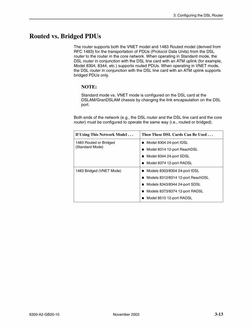
Routed vs. Bridged PDUs
The router supports both the VNET model and 1483 Routed model (derived from RFC 1483) for the transportation of PDUs (Protocol Data Units) from the DSL router to the router in the core network. When operating in Standard mode, the DSL router in conjunction with the DSL line card with an ATM uplink (for example, Model 8304, 8344, etc.) supports routed PDUs. When operating in VNET mode, the DSL router in conjunction with the DSL line card with an ATM uplink supports bridged PDUs only.
NOTE:
Standard mode vs. VNET mode is configured on the DSL card at the DSLAM/GranDSLAM chassis by changing the link encapsulation on the DSL port.
Both ends of the network (e.g., the DSL router and the DSL line card and the core router) must be configured to operate the same way (i.e., routed or bridged).
If Using This Network Model . . . Then These DSL Cards Can Be Used . . .
1483 Routed or Bridged (Standard Mode)
� Model 8304 24-port IDSL
� Model 8314 12-port ReachDSL
� Model 8344 24-port SDSL
� Model 8374 12-port RADSL
1483 Bridged (VNET Mode) � Models 8303/8304 24-port IDSL
� Models 8312/8314 12-port ReachDSL
� Models 8343/8344 24-port SDSL
� Models 8373/8374 12-port RADSL
� Model 8510 12-port RADSL
3. Configuring the DSL Router
3-14 November 2003 6300-A2-GB20-10
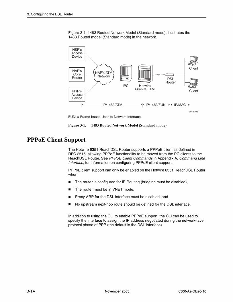
Figure 3-1, 1483 Routed Network Model (Standard mode), illustrates the 1483 Routed model (Standard mode) in the network.
FUNI = Frame-based User-to-Network Interface
Figure 3-1. 1483 Routed Network Model (Standard mode)
PPPoE Client Support
The Hotwire 6351 ReachDSL Router supports a PPPoE client as defined in RFC 2516, allowing PPPoE functionality to be moved from the PC clients to the ReachDSL Router. See PPPoE Client Commands in Appendix A, Command Line Interface, for information on configuring PPPoE client support.
PPPoE client support can only be enabled on the Hotwire 6351 ReachDSL Router when:
� The router is configured for IP Routing (bridging must be disabled),
� The router must be in VNET mode,
� Proxy ARP for the DSL interface must be disabled, and
� No upstream next-hop route should be defined for the DSL interface.
In addition to using the CLI to enable PPPoE support, the CLI can be used to specify the interface to assign the IP address negotiated during the network-layer protocol phase of PPP (the default is the DSL interface).
O I
ALARMS
Major MinorFanBA
POWER
IPC HotwireGranDSLAM
DSLRouter
Client
NSP'sAccessDevice
NAP'sCore
RouterNAP's ATM
Network
Client
IP/MACIP/1483/FUNIIP/1483/ATM
00-16802
NSP'sAccessDevice
3. Configuring the DSL Router
6300-A2-GB20-10 November 2003 3-15
Once the PPP-negotiated IP address is assigned, the ReachDSL Router’s configuration database will automatically be converted to a new configuration determined by this IP address and the interface to which it is assigned. However, any changes made to the interface assignment for the PPP-negotiated IP address do not take effect until the next time the PPP link is established. This new configuration will result in the following:
� The DSL and/or Ethernet interface(s) are reconfigured.
� Routes associated with any interfaces that have been removed are deleted. An exception to this is when the negotiated IP address is assigned to the Ethernet interface and the subnet defined by the interface’s IP address is the same as the one defined by the negotiated IP address.
� All dynamic ARP entries are removed. All static ARP entries associated with the DSL interface and any removed interfaces are deleted. Static ARP entries for the Ethernet interface are retained if the negotiated IP address is assigned to the Ethernet interface and the subnet defined by the interface’s IP address is the same as the one defined by the negotiated IP address.
� The negotiated IP address automatically becomes the primary IP address and the NAPT public IP address.
� An active service domain Telnet session is terminated if the interface associated with the session is removed or the IP address of the interface is changing.
� All DHCP bindings and BOOTP Relay Agent snoop information are removed if the subnet defined by the Ethernet IP address changes. If the new Ethernet IP address is still in the same subnet, then only the binding and snoop information that conflicts with this IP address is removed.
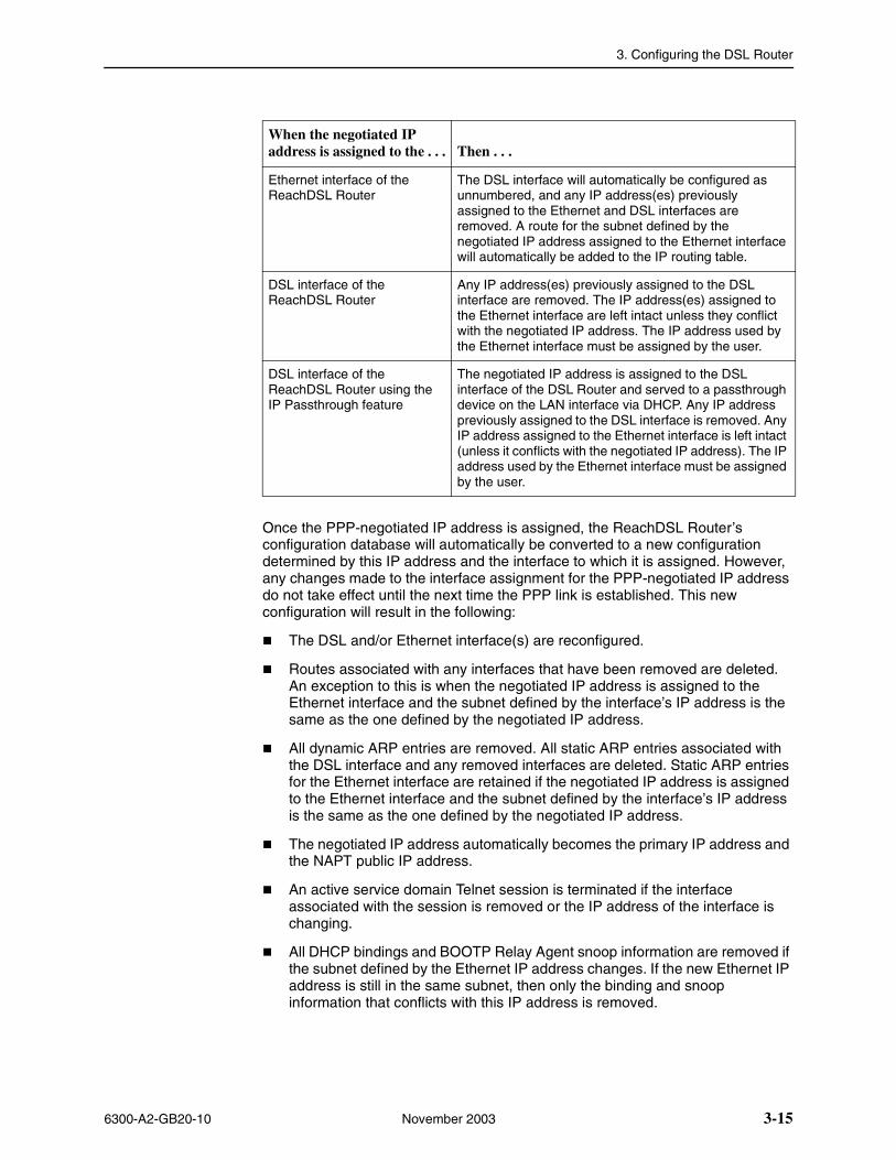
When the negotiated IP address is assigned to the . . . Then . . .
Ethernet interface of the ReachDSL Router
The DSL interface will automatically be configured as unnumbered, and any IP address(es) previously assigned to the Ethernet and DSL interfaces are removed. A route for the subnet defined by the negotiated IP address assigned to the Ethernet interface will automatically be added to the IP routing table.
DSL interface of the ReachDSL Router
Any IP address(es) previously assigned to the DSL interface are removed. The IP address(es) assigned to the Ethernet interface are left intact unless they conflict with the negotiated IP address. The IP address used by the Ethernet interface must be assigned by the user.
DSL interface of the ReachDSL Router using the IP Passthrough feature
The negotiated IP address is assigned to the DSL interface of the DSL Router and served to a passthrough device on the LAN interface via DHCP. Any IP address previously assigned to the DSL interface is removed. Any IP address assigned to the Ethernet interface is left intact (unless it conflicts with the negotiated IP address). The IP address used by the Ethernet interface must be assigned by the user.

3. Configuring the DSL Router
3-16 November 2003 6300-A2-GB20-10
� If the DSL interface IP address changes, the Basic NAT static mapping that conflicts with the new DSL IP interface address and all Basic NAT dynamic mappings are removed.
� If the IP Passthrough feature is used, the DHCP Server feature is automatically enabled and the negotiated IP address is the only IP address served. In addition, the derived subnet mask, discovered peer IP address, and negotiated DNS server addresses (unless explicitly directed not to use the DNS addresses) are configured as the DHCP options provided to the client.
6300-A2-GB20-10 November 2003 4-1
4DSL Router Configuration Examples
Configuration Examples
The Hotwire DSL Router configuration examples in this chapter include only a few of the possible scenarios. This chapter covers some of the common configurations. The command syntax will vary based on your network setup.
Configuration commands require the access level of Administrator-Config and changes need to be saved while in configuration mode to take effect. Refer to Chapter 2, Accessing the DSL Router.
The Hotwire DSL Router configuration examples include:
� Basic Bridging Configuration Example
� Basic Routing Configuration Example
� Basic NAT Configuration Example
� NAPT Configuration Example
� Simultaneous Basic NAT and NAPT Configuration Example
� Unnumbered DSL Interface with Proxy ARP Configuration Example
� DHCP Relay with Proxy ARP Configuration Example
� DHCP Server with Basic NAT Configuration Example
� PPPoE Client with NAPT and DHCP Server Configuration Example
� Downstream Router Configuration Example
� IP Passthrough Configuration Example
Refer to Appendix A, Command Line Interface, for specific commands and their syntax. Refer to Appendix B, Configuration Defaults and Command Line Shortcuts, for specific command default settings and abbreviated command line syntax.
4. DSL Router Configuration Examples
4-2 November 2003 6300-A2-GB20-10
NOTES:
— Configuration examples included in this chapter cover some common configurations, providing only a few of the possible scenarios.
— IP addresses used in the examples are for illustrative purposes only; they are not intended to be used when configuring your local network.
— Adding static routes to the core router is typically necessary when routing is enabled.
— Bridging-only mode is the default configuration.
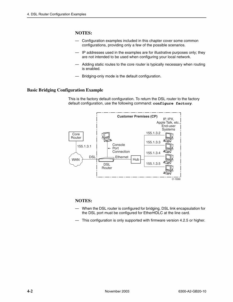
Basic Bridging Configuration Example
This is the factory default configuration. To return the DSL router to the factory default configuration, use the following command: configure factory.
NOTES:
— When the DSL router is configured for bridging, DSL link encapsulation for the DSL port must be configured for EtherHDLC at the line card.
— This configuration is only supported with firmware version 4.2.5 or higher.
01-16966
Customer Premises (CP)
DSLRouter
Hub
155.1.3.2
155.1.3.3
155.1.3.4
IP, IPX,Apple Talk, etc.,
End-userSystems
ConsolePortConnection
EthernetDSL
CoreRouter
WAN
155.1.3.1
155.1.3.5
4. DSL Router Configuration Examples
6300-A2-GB20-10 November 2003 4-3
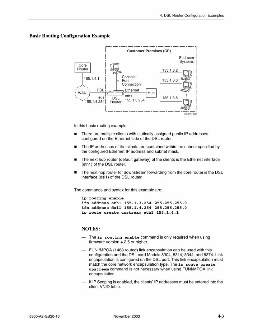
Basic Routing Configuration Example
In this basic routing example:
� There are multiple clients with statically assigned public IP addresses configured on the Ethernet side of the DSL router.
� The IP addresses of the clients are contained within the subnet specified by the configured Ethernet IP address and subnet mask.
� The next hop router (default gateway) of the clients is the Ethernet interface (eth1) of the DSL router.
� The next hop router for downstream forwarding from the core router is the DSL interface (dsl1) of the DSL router.
The commands and syntax for this example are:
ip routing enableifn address eth1 155.1.3.254 255.255.255.0ifn address dsl1 155.1.4.254 255.255.255.0ip route create upstream eth1 155.1.4.1
NOTES:
— The ip routing enable command is only required when using firmware version 4.2.5 or higher.
— FUNI/MPOA (1483 routed) link encapsulation can be used with this configuration and the DSL card Models 8304, 8314, 8344, and 8374. Link encapsulation is configured on the DSL port. This link encapsulation must match the core network encapsulation type. The ip route create upstream command is not necessary when using FUNI/MPOA link encapsulation.
— If IP Scoping is enabled, the clients’ IP addresses must be entered into the client VNID table.
01-16613-02
Customer Premises (CP)
DSLRouter
Hub
155.1.3.2
155.1.3.3
155.1.3.8
End-userSystems
ConsolePortConnection
Ethernet
eth1155.1.3.254
DSL
CoreRouter
dsl1155.1.4.254
WAN
155.1.4.1
4. DSL Router Configuration Examples
4-4 November 2003 6300-A2-GB20-10
To enable Telnet through the service domain via the DSL router Ethernet (eth1) port, use the following commands:
telnet enabletelnet login enabletelnet name create admin paradyne abc123
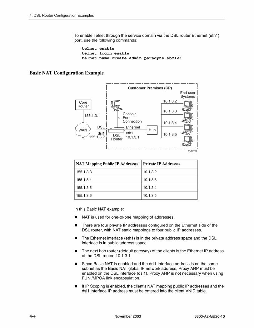
Basic NAT Configuration Example
In this Basic NAT example:
� NAT is used for one-to-one mapping of addresses.
� There are four private IP addresses configured on the Ethernet side of the DSL router, with NAT static mappings to four public IP addresses.
� The Ethernet interface (eth1) is in the private address space and the DSL interface is in public address space.
� The next hop router (default gateway) of the clients is the Ethernet IP address of the DSL router, 10.1.3.1.
� Since Basic NAT is enabled and the dsl1 interface address is on the same subnet as the Basic NAT global IP network address, Proxy ARP must be enabled on the DSL interface (dsl1). Proxy ARP is not necessary when using FUNI/MPOA link encapsulation.
� If IP Scoping is enabled, the client’s NAT mapping public IP addresses and the dsl1 interface IP address must be entered into the client VNID table.
NAT Mapping Public IP Addresses Private IP Addresses
155.1.3.3 10.1.3.2
155.1.3.4 10.1.3.3
155.1.3.5 10.1.3.4
155.1.3.6 10.1.3.5
00-16767
Customer Premises (CP)
DSLRouter
Hub
10.1.3.2
10.1.3.3
10.1.3.4
End-userSystems
ConsolePortConnection
Ethernet
eth110.1.3.1
DSL
CoreRouter
dsl1155.1.3.2
WAN
155.1.3.1
10.1.3.5
4. DSL Router Configuration Examples
6300-A2-GB20-10 November 2003 4-5
The commands and syntax for this example are:
ip routing enableifn address eth1:1 10.1.3.1 255.255.255.0ifn address dsl1 155.1.3.2 255.255.255.0ip route create upstream eth1 155.1.3.1nat basic address 155.1.3.0nat basic map 155.1.3.3 10.1.3.2 10.1.3.5nat basic enableproxy arp dsl1 enable
NOTES:
— The IP address assigned for the DSL interface and the IP address in NAT static mappings can be in the same subnet, but cannot be the same IP address.
— When IP Scoping is enabled, Basic NAT is enabled and the dsl1 interface is NOT part of the Basic NAT global IP network, only the dsl1 interface’s IP address must be entered into the client VNID table.
— The ip routing enable command is only required when using firmware version 4.2.5 or higher.
— FUNI/MPOA (1483 routed) link encapsulation can be used with this configuration and the DSL card Models 8304, 8314, 8344, and 8374. Link encapsulation is configured on the DSL port. This link encapsulation must match the core network encapsulation type. The ip route create upstream and proxy arp dsl1 enable commands are not necessary when using FUNI/MPOA link encapsulation.
4. DSL Router Configuration Examples
4-6 November 2003 6300-A2-GB20-10
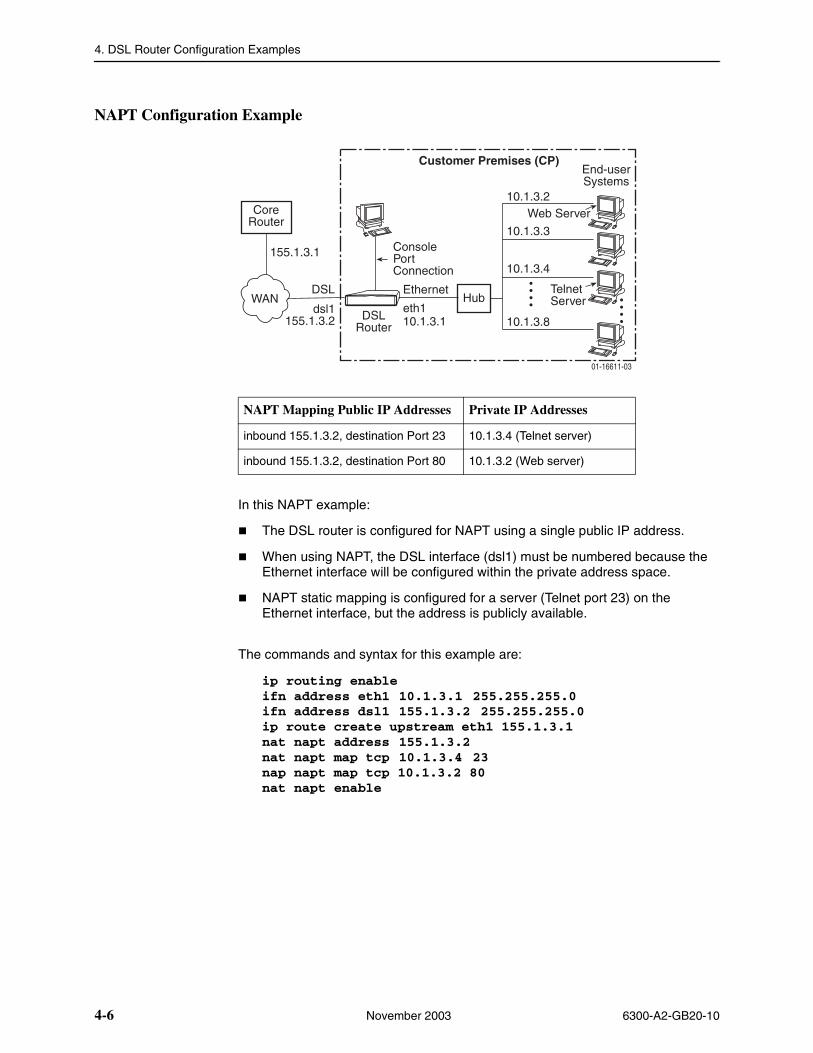
NAPT Configuration Example
In this NAPT example:
� The DSL router is configured for NAPT using a single public IP address.
� When using NAPT, the DSL interface (dsl1) must be numbered because the Ethernet interface will be configured within the private address space.
� NAPT static mapping is configured for a server (Telnet port 23) on the Ethernet interface, but the address is publicly available.
The commands and syntax for this example are:
ip routing enableifn address eth1 10.1.3.1 255.255.255.0ifn address dsl1 155.1.3.2 255.255.255.0ip route create upstream eth1 155.1.3.1nat napt address 155.1.3.2nat napt map tcp 10.1.3.4 23nap napt map tcp 10.1.3.2 80nat napt enable
NAPT Mapping Public IP Addresses Private IP Addresses
inbound 155.1.3.2, destination Port 23 10.1.3.4 (Telnet server)
inbound 155.1.3.2, destination Port 80 10.1.3.2 (Web server)
01-16611-03
Customer Premises (CP)
DSLRouter
Hub
10.1.3.2
10.1.3.3
10.1.3.4
End-userSystems
ConsolePortConnection
Ethernet
eth110.1.3.1
DSL
CoreRouter
dsl1155.1.3.2
WAN
155.1.3.1
10.1.3.8
TelnetServer
Web Server
4. DSL Router Configuration Examples
6300-A2-GB20-10 November 2003 4-7
NOTES:
— The ip routing enable command is only required when using firmware version 4.2.5 or higher.
— FUNI/MPOA (1483 routed) link encapsulation can be used with this configuration and the DSL card Models 8304, 8314, 8344, and 8374. Link encapsulation is configured on the DSL port. This link encapsulation must match the core network encapsulation type. The ip route create upstream command is not necessary when using FUNI/MPOA link encapsulation.
— NAPT is limited to one subnet.
4. DSL Router Configuration Examples
4-8 November 2003 6300-A2-GB20-10
Simultaneous Basic NAT and NAPT Configuration Example
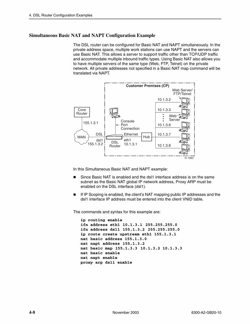
The DSL router can be configured for Basic NAT and NAPT simultaneously. In the private address space, multiple work stations can use NAPT and the servers can use Basic NAT. This allows a server to support traffic other than TCP/UDP traffic and accommodate multiple inbound traffic types. Using Basic NAT also allows you to have multiple servers of the same type (Web, FTP, Telnet) on the private network. All private addresses not specified in a Basic NAT map command will be translated via NAPT.
In this Simultaneous Basic NAT and NAPT example:
� Since Basic NAT is enabled and the dsl1 interface address is on the same subnet as the Basic NAT global IP network address, Proxy ARP must be enabled on the DSL interface (dsl1).
� If IP Scoping is enabled, the client’s NAT mapping public IP addresses and the dsl1 interface IP address must be entered into the client VNID table.
The commands and syntax for this example are:
ip routing enableifn address eth1 10.1.3.1 255.255.255.0ifn address dsl1 155.1.3.2 255.255.255.0ip route create upstream eth1 155.1.3.1nat basic address 155.1.3.0nat napt address 155.1.3.2nat basic map 155.1.3.3 10.1.3.2 10.1.3.3nat basic enablenat napt enableproxy arp dsl1 enable
01-16967
Customer Premises (CP)
DSLRouter
Hub
10.1.3.3
10.1.3.6
10.1.3.7
Web Server/FTP/Telnet
ConsolePortConnection
Ethernet
eth110.1.3.1
DSL
CoreRouter
dsl1155.1.3.2
WAN
155.1.3.1
10.1.3.8
10.1.3.2
WebServer
4. DSL Router Configuration Examples
6300-A2-GB20-10 November 2003 4-9
NOTES:
— When IP Scoping is enabled, Basic NAT is enabled and the dsl1 interface is NOT part of the Basic NAT global IP network, only the dsl1 interface’s IP address must be entered into the client VNID table.
— This configuration is only supported with firmware version 4.2.5 or higher.
— FUNI/MPOA (1483 routed) link encapsulation can be used with this configuration and the DSL card Models 8304, 8314, 8344, and 8374. Link encapsulation is configured on the DSL port. This link encapsulation must match the core network encapsulation type. The ip route create upstream and proxy arp dsl1 enable commands are not necessary when using FUNI/MPOA link encapsulation.
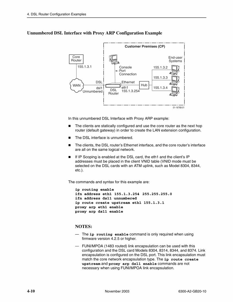
4. DSL Router Configuration Examples
4-10 November 2003 6300-A2-GB20-10
Unnumbered DSL Interface with Proxy ARP Configuration Example
In this unnumbered DSL Interface with Proxy ARP example:
� The clients are statically configured and use the core router as the next hop router (default gateway) in order to create the LAN extension configuration.
� The DSL interface is unnumbered.
� The clients, the DSL router’s Ethernet interface, and the core router’s interface are all on the same logical network.
� If IP Scoping is enabled at the DSL card, the eth1 and the client’s IP addresses must be placed in the client VNID table (VNID mode must be selected on the DSL cards with an ATM uplink, such as Model 8304, 8344, etc.).
The commands and syntax for this example are:
ip routing enableifn address eth1 155.1.3.254 255.255.255.0ifn address dsl1 unnumberedip route create upstream eth1 155.1.3.1proxy arp eth1 enableproxy arp dsl1 enable
NOTES:
— The ip routing enable command is only required when using firmware version 4.2.5 or higher.
— FUNI/MPOA (1483 routed) link encapsulation can be used with this configuration and the DSL card Models 8304, 8314, 8344, and 8374. Link encapsulation is configured on the DSL port. This link encapsulation must match the core network encapsulation type. The ip route create upstream and proxy arp dsl1 enable commands are not necessary when using FUNI/MPOA link encapsulation.
01-16768-01
Customer Premises (CP)
End-userSystems
155.1.3.2
155.1.3.3
155.1.3.4DSL
Router
Hub
ConsolePortConnection
DSL
CoreRouter
dsl1Unnumbered
WAN
155.1.3.1
eth1155.1.3.254
Ethernet
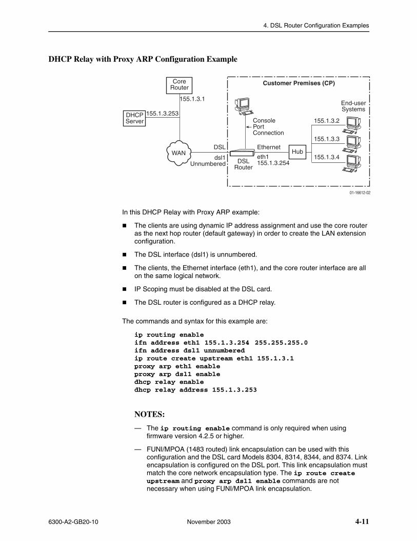
4. DSL Router Configuration Examples
6300-A2-GB20-10 November 2003 4-11
DHCP Relay with Proxy ARP Configuration Example
In this DHCP Relay with Proxy ARP example:
� The clients are using dynamic IP address assignment and use the core router as the next hop router (default gateway) in order to create the LAN extension configuration.
� The DSL interface (dsl1) is unnumbered.
� The clients, the Ethernet interface (eth1), and the core router interface are all on the same logical network.
� IP Scoping must be disabled at the DSL card.
� The DSL router is configured as a DHCP relay.
The commands and syntax for this example are:
ip routing enableifn address eth1 155.1.3.254 255.255.255.0ifn address dsl1 unnumberedip route create upstream eth1 155.1.3.1proxy arp eth1 enableproxy arp dsl1 enabledhcp relay enabledhcp relay address 155.1.3.253
NOTES:
— The ip routing enable command is only required when using firmware version 4.2.5 or higher.
— FUNI/MPOA (1483 routed) link encapsulation can be used with this configuration and the DSL card Models 8304, 8314, 8344, and 8374. Link encapsulation is configured on the DSL port. This link encapsulation must match the core network encapsulation type. The ip route create upstream and proxy arp dsl1 enable commands are not necessary when using FUNI/MPOA link encapsulation.
01-16612-02
Customer Premises (CP)
End-userSystems
155.1.3.2
155.1.3.3
155.1.3.4DSL
Router
Hub
ConsolePortConnection
DSL
CoreRouter
dsl1Unnumbered
WAN
155.1.3.1
eth1155.1.3.254
Ethernet
DHCPServer
155.1.3.253
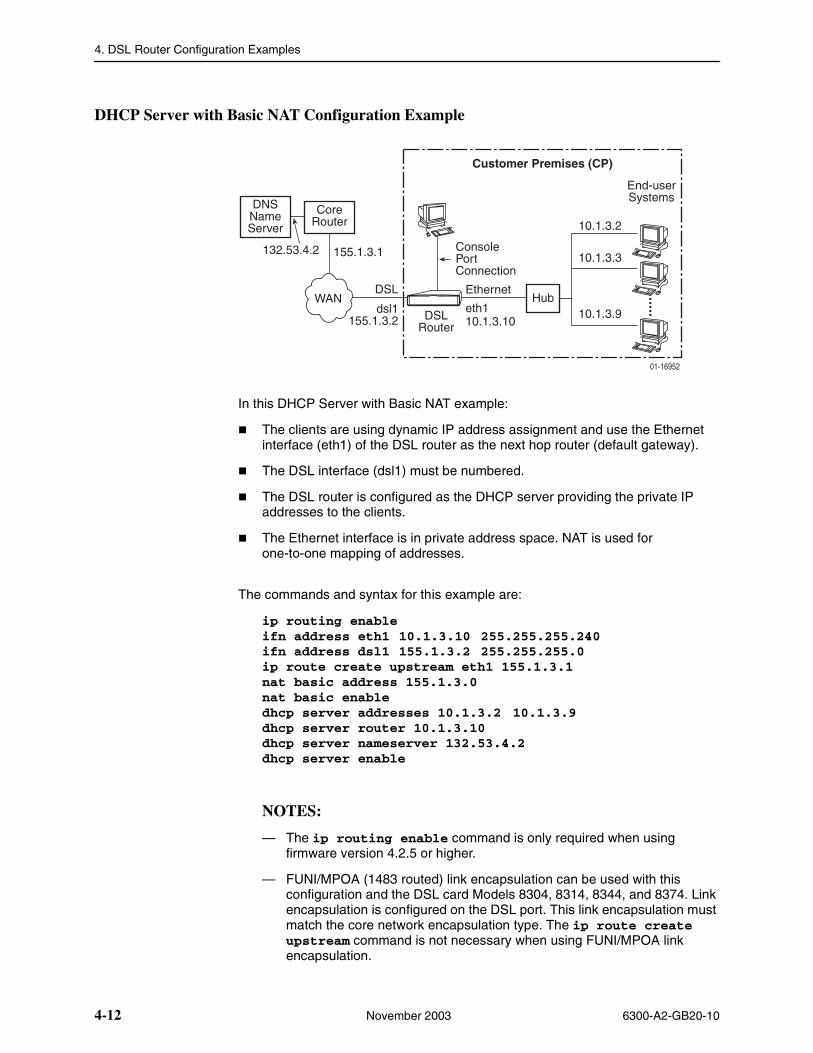
4. DSL Router Configuration Examples
4-12 November 2003 6300-A2-GB20-10
DHCP Server with Basic NAT Configuration Example
In this DHCP Server with Basic NAT example:
� The clients are using dynamic IP address assignment and use the Ethernet interface (eth1) of the DSL router as the next hop router (default gateway).
� The DSL interface (dsl1) must be numbered.
� The DSL router is configured as the DHCP server providing the private IP addresses to the clients.
� The Ethernet interface is in private address space. NAT is used for one-to-one mapping of addresses.
The commands and syntax for this example are:
ip routing enableifn address eth1 10.1.3.10 255.255.255.240ifn address dsl1 155.1.3.2 255.255.255.0ip route create upstream eth1 155.1.3.1nat basic address 155.1.3.0nat basic enabledhcp server addresses 10.1.3.2 10.1.3.9dhcp server router 10.1.3.10dhcp server nameserver 132.53.4.2dhcp server enable
NOTES:
— The ip routing enable command is only required when using firmware version 4.2.5 or higher.
— FUNI/MPOA (1483 routed) link encapsulation can be used with this configuration and the DSL card Models 8304, 8314, 8344, and 8374. Link encapsulation is configured on the DSL port. This link encapsulation must match the core network encapsulation type. The ip route create upstream command is not necessary when using FUNI/MPOA link encapsulation.
01-16952
Customer Premises (CP)
DSLRouter
Hub
10.1.3.2
10.1.3.3
10.1.3.9
End-userSystems
ConsolePortConnection
Ethernet
eth110.1.3.10
DSL
CoreRouter
dsl1155.1.3.2
WAN
155.1.3.1
DNSNameServer
132.53.4.2
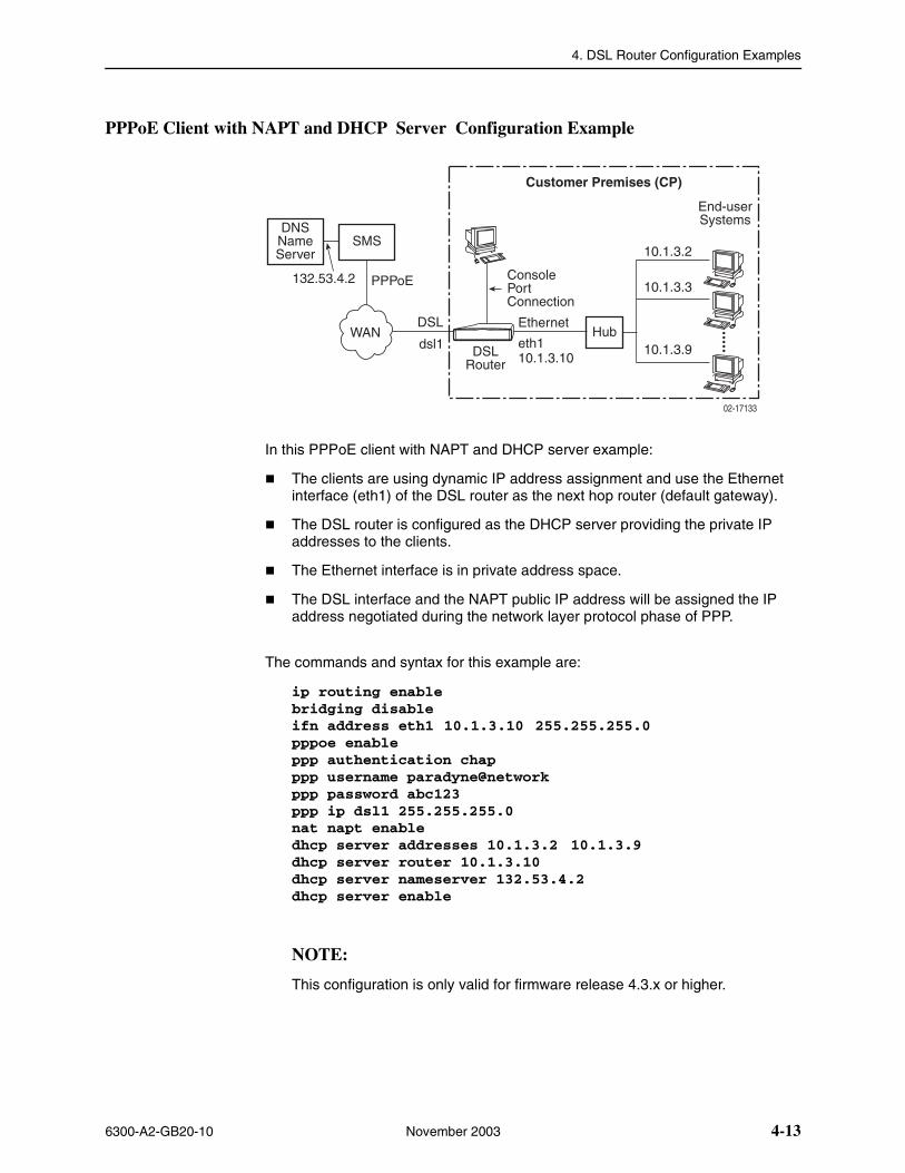
4. DSL Router Configuration Examples
6300-A2-GB20-10 November 2003 4-13
PPPoE Client with NAPT and DHCP Server Configuration Example
In this PPPoE client with NAPT and DHCP server example:
� The clients are using dynamic IP address assignment and use the Ethernet interface (eth1) of the DSL router as the next hop router (default gateway).
� The DSL router is configured as the DHCP server providing the private IP addresses to the clients.
� The Ethernet interface is in private address space.
� The DSL interface and the NAPT public IP address will be assigned the IP address negotiated during the network layer protocol phase of PPP.
The commands and syntax for this example are:
ip routing enablebridging disableifn address eth1 10.1.3.10 255.255.255.0pppoe enableppp authentication chapppp username paradyne@networkppp password abc123ppp ip dsl1 255.255.255.0nat napt enabledhcp server addresses 10.1.3.2 10.1.3.9dhcp server router 10.1.3.10dhcp server nameserver 132.53.4.2dhcp server enable
NOTE:
This configuration is only valid for firmware release 4.3.x or higher.
02-17133
Customer Premises (CP)
DSLRouter
Hub
10.1.3.2
10.1.3.3
10.1.3.9
End-userSystems
ConsolePortConnection
Ethernet
eth110.1.3.10
DSL
SMS
dsl1WAN
PPPoE
DNSNameServer
132.53.4.2
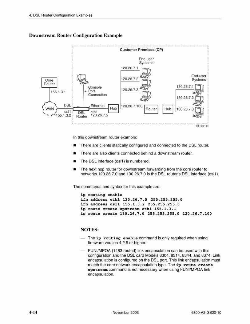
4. DSL Router Configuration Examples
4-14 November 2003 6300-A2-GB20-10
Downstream Router Configuration Example
In this downstream router example:
� There are clients statically configured and connected to the DSL router.
� There are also clients connected behind a downstream router.
� The DSL interface (dsl1) is numbered.
� The next hop router for downstream forwarding from the core router to networks 120.26.7.0 and 130.26.7.0 is the DSL router’s DSL interface (dsl1).
The commands and syntax for this example are:
ip routing enableifn address eth1 120.26.7.5 255.255.255.0ifn address dsl1 155.1.3.2 255.255.255.0ip route create upstream eth1 155.1.3.1ip route create 130.26.7.0 255.255.255.0 120.26.7.100
NOTES:
— The ip routing enable command is only required when using firmware version 4.2.5 or higher.
— FUNI/MPOA (1483 routed) link encapsulation can be used with this configuration and the DSL card Models 8304, 8314, 8344, and 8374. Link encapsulation is configured on the DSL port. This link encapsulation must match the core network encapsulation type. The ip route create upstream command is not necessary when using FUNI/MPOA link encapsulation.
00-16591-01
Customer Premises (CP)
End-userSystems
Router Hub
End-userSystems
120.26.7.1
120.26.7.2
120.26.7.3
120.26.7.100
130.26.7.1
130.26.7.2
130.26.7.3DSL
Router
Hub
ConsolePortConnection
DSL
CoreRouter
dsl1155.1.3.2
WAN
155.1.3.1
eth1120.26.7.5
Ethernet
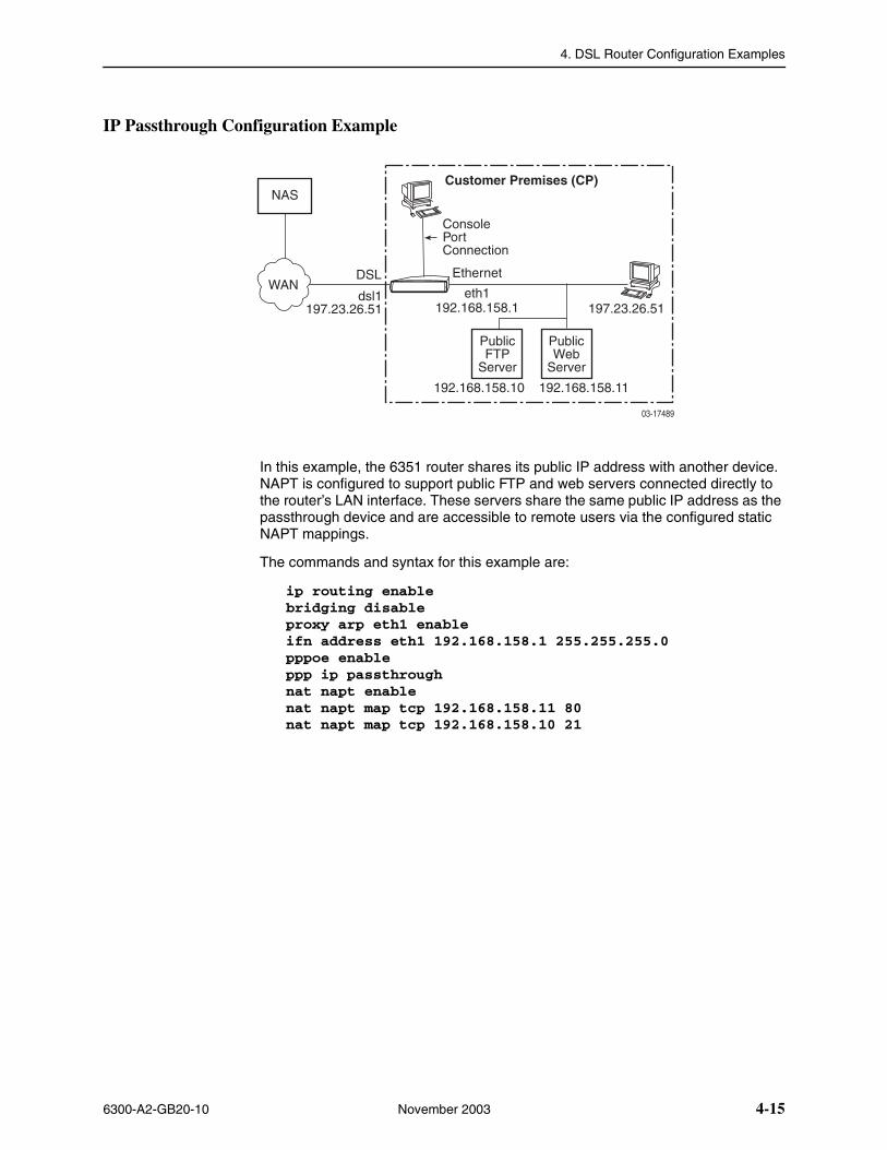
4. DSL Router Configuration Examples
6300-A2-GB20-10 November 2003 4-15
IP Passthrough Configuration Example
In this example, the 6351 router shares its public IP address with another device. NAPT is configured to support public FTP and web servers connected directly to the router’s LAN interface. These servers share the same public IP address as the passthrough device and are accessible to remote users via the configured static NAPT mappings.
The commands and syntax for this example are:
ip routing enablebridging disable proxy arp eth1 enable ifn address eth1 192.168.158.1 255.255.255.0 pppoe enable ppp ip passthrough nat napt enable nat napt map tcp 192.168.158.11 80 nat napt map tcp 192.168.158.10 21
��������
�����������������
������������
�� �����������
��������
�����������������
���
���
�� �������������
���
��� �� !����"��
��� ��������"��
�������������# ��������������

4. DSL Router Configuration Examples
4-16 November 2003 6300-A2-GB20-10
6300-A2-GB20-10 November 2003 5-1
5Monitoring the DSL Router
Monitoring the Router
The DSL router detects and reports problem conditions that you can monitor. The following indicators can alert you to possible problems:
� LEDs
On the DSL router’s front panel. Refer to LED Status on page 5-2.
� Status Messages
For the Ethernet and DSL interface links. Refer to Interface Status on page 5-3.
� Performance Statistics
For service and management domains, Ethernet and DSL interface and links, IP processing, and bridge operation. Refer to Performance Statistics on page 5-3.
� SNMP Traps
For the current status of the router’s SNMP traps, if enabled. Refer to Appendix C, Traps and MIBs.
When a problem is detected, refer to Chapter 6, Diagnostics and Troubleshooting, for information regarding diagnostic tests, System Log messages, and troubleshooting.
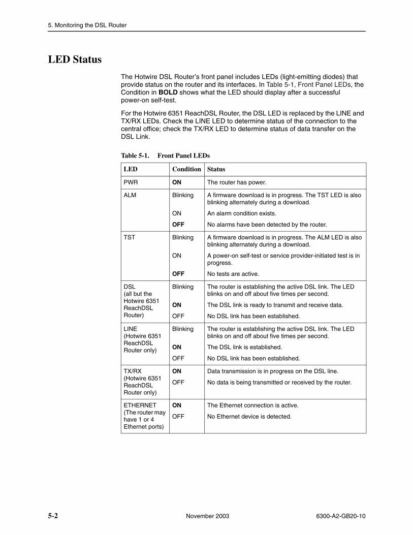
5. Monitoring the DSL Router
5-2 November 2003 6300-A2-GB20-10
LED Status
The Hotwire DSL Router’s front panel includes LEDs (light-emitting diodes) that provide status on the router and its interfaces. In Table 5-1, Front Panel LEDs, the Condition in BOLD shows what the LED should display after a successful power-on self-test.
For the Hotwire 6351 ReachDSL Router, the DSL LED is replaced by the LINE and TX/RX LEDs. Check the LINE LED to determine status of the connection to the central office; check the TX/RX LED to determine status of data transfer on the DSL Link.
Table 5-1. Front Panel LEDs
LED Condition Status
PWR ON The router has power.
ALM Blinking
ON
OFF
A firmware download is in progress. The TST LED is also blinking alternately during a download.
An alarm condition exists.
No alarms have been detected by the router.
TST Blinking
ON
OFF
A firmware download is in progress. The ALM LED is also blinking alternately during a download.
A power-on self-test or service provider-initiated test is in progress.
No tests are active.
DSL (all but the Hotwire 6351ReachDSL Router)
Blinking
ON
OFF
The router is establishing the active DSL link. The LED blinks on and off about five times per second.
The DSL link is ready to transmit and receive data.
No DSL link has been established.
LINE (Hotwire 6351ReachDSL Router only)
Blinking
ON
OFF
The router is establishing the active DSL link. The LED blinks on and off about five times per second.
The DSL link is established.
No DSL link has been established.
TX/RX (Hotwire 6351ReachDSL Router only)
ON
OFF
Data transmission is in progress on the DSL line.
No data is being transmitted or received by the router.
ETHERNET (The router may have 1 or 4 Ethernet ports)
ON
OFF
The Ethernet connection is active.
No Ethernet device is detected.
5. Monitoring the DSL Router
6300-A2-GB20-10 November 2003 5-3
Interface Status
Current status of the Ethernet (eth1) or DSL (dsl1) interface can be accessed using the show interface CLI command.
Information provided about each interface includes the direction of the link, the MAC address, Proxy ARP setting, the numbered interfaces, their IP addresses and subnet masks.
See show interface {eth1 | dsl1} on page A-27 in Appendix A, Command Line Interface, for information about the command and what is displayed when the command is entered.
NOTE:
The Primary designation of a numbered interface (e.g., eth1:1) marks that interface as the one that uses its IP address as a Router ID. If no interface is defined as Primary, the last numbered interface that was created becomes the Primary IP Address.
Performance Statistics
Performance statistics are available for the DSL and Ethernet interfaces, for IP processing, and for the bridge using the show statistics CLI command. These statistics are above and beyond what is collected and reported at the DSLAM.
See show statistics [eth1 | dsl1 | ip | bridge| pppoe | tftp] on page A-30 in Appendix A, Command Line Interface, for information about the command and what is displayed when the command is entered.
Clearing Statistics
The CLI allows you to clear a set of statistics, resetting the counts to zero. Refer to Clearing Statistics Command in Appendix A, Command Line Interface, for additional information.
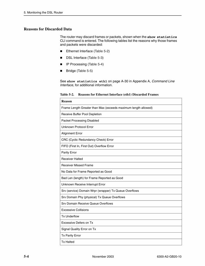
5. Monitoring the DSL Router
5-4 November 2003 6300-A2-GB20-10
Reasons for Discarded Data
The router may discard frames or packets, shown when the show statistics CLI command is entered. The following tables list the reasons why those frames and packets were discarded:
� Ethernet Interface (Table 5-2)
� DSL Interface (Table 5-3)
� IP Processing (Table 5-4)
� Bridge (Table 5-5)
See show statistics eth1 on page A-30 in Appendix A, Command Line Interface, for additional information.
Table 5-2. Reasons for Ethernet Interface (eth1) Discarded Frames
Reason
Frame Length Greater than Max (exceeds maximum length allowed)
Receive Buffer Pool Depletion
Packet Processing Disabled
Unknown Protocol Error
Alignment Error
CRC (Cyclic Redundancy Check) Error
FIFO (First In, First Out) Overflow Error
Parity Error
Receiver Halted
Receiver Missed Frame
No Data for Frame Reported as Good
Bad Len (length) for Frame Reported as Good
Unknown Receive Interrupt Error
Srv (service) Domain Wrpr (wrapper) Tx Queue Overflows
Srv Domain Phy (physical) Tx Queue Overflows
Srv Domain Receive Queue Overflows
Excessive Collisions
Tx Underflow
Excessive Defers on Tx
Signal Quality Error on Tx
Tx Parity Error
Tx Halted
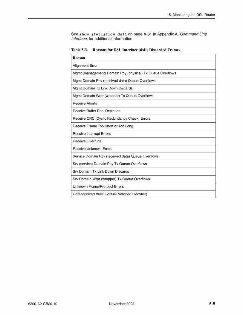
5. Monitoring the DSL Router
6300-A2-GB20-10 November 2003 5-5
See show statistics dsl1 on page A-31 in Appendix A, Command Line Interface, for additional information.
Table 5-3. Reasons for DSL Interface (dsl1) Discarded Frames
Reason
Alignment Error
Mgmt (management) Domain Phy (physical) Tx Queue Overflows
Mgmt Domain Rcv (received data) Queue Overflows
Mgmt Domain Tx Link Down Discards
Mgmt Domain Wrpr (wrapper) Tx Queue Overflows
Receive Aborts
Receive Buffer Pool Depletion
Receive CRC (Cyclic Redundancy Check) Errors
Receive Frame Too Short or Too Long
Receive Interrupt Errors
Receive Overruns
Receive Unknown Errors
Service Domain Rcv (received data) Queue Overflows
Srv (service) Domain Phy Tx Queue Overflows
Srv Domain Tx Link Down Discards
Srv Domain Wrpr (wrapper) Tx Queue Overflows
Unknown Frame/Protocol Errors
Unrecognized VNID (Virtual Network IDentifier)
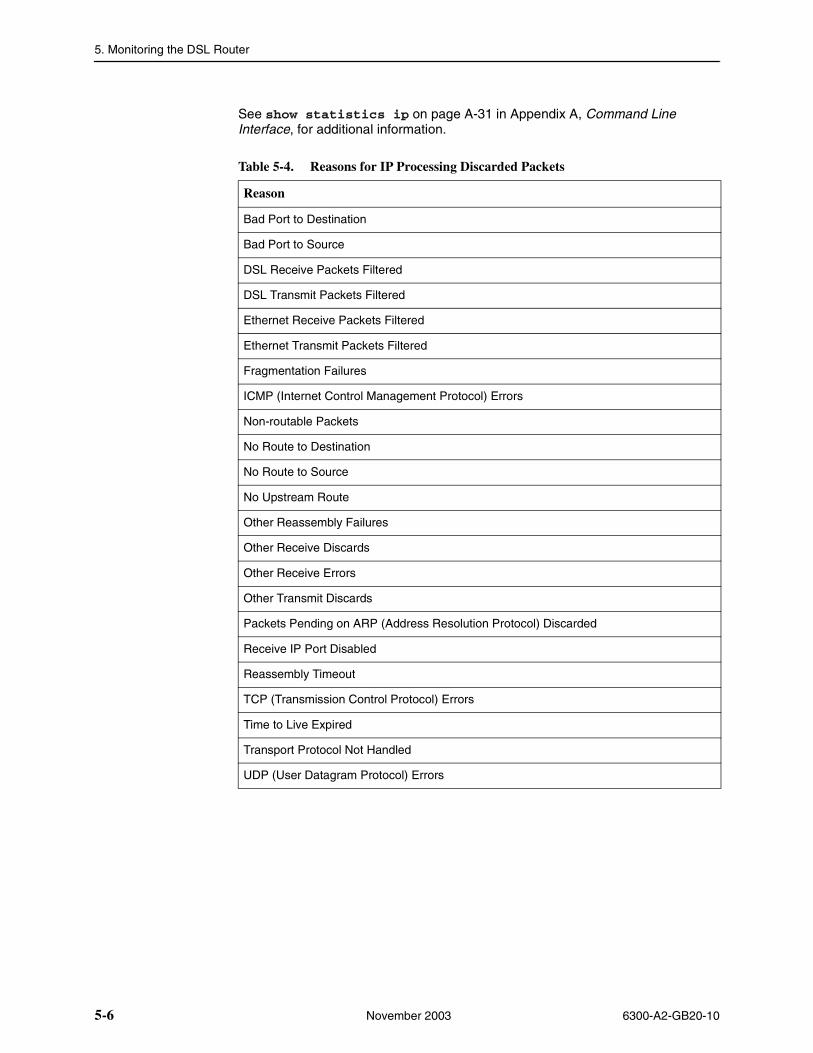
5. Monitoring the DSL Router
5-6 November 2003 6300-A2-GB20-10
See show statistics ip on page A-31 in Appendix A, Command Line Interface, for additional information.
Table 5-4. Reasons for IP Processing Discarded Packets
Reason
Bad Port to Destination
Bad Port to Source
DSL Receive Packets Filtered
DSL Transmit Packets Filtered
Ethernet Receive Packets Filtered
Ethernet Transmit Packets Filtered
Fragmentation Failures
ICMP (Internet Control Management Protocol) Errors
Non-routable Packets
No Route to Destination
No Route to Source
No Upstream Route
Other Reassembly Failures
Other Receive Discards
Other Receive Errors
Other Transmit Discards
Packets Pending on ARP (Address Resolution Protocol) Discarded
Receive IP Port Disabled
Reassembly Timeout
TCP (Transmission Control Protocol) Errors
Time to Live Expired
Transport Protocol Not Handled
UDP (User Datagram Protocol) Errors
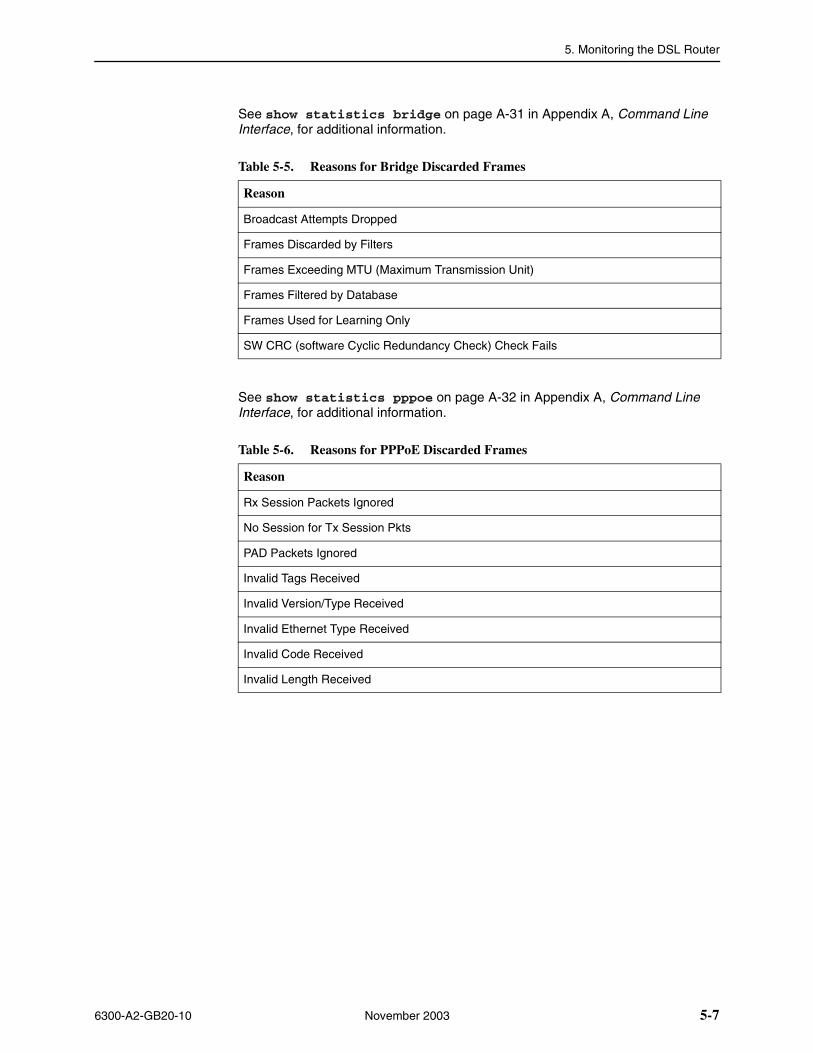
5. Monitoring the DSL Router
6300-A2-GB20-10 November 2003 5-7
See show statistics bridge on page A-31 in Appendix A, Command Line Interface, for additional information.
See show statistics pppoe on page A-32 in Appendix A, Command Line Interface, for additional information.
Table 5-5. Reasons for Bridge Discarded Frames
Reason
Broadcast Attempts Dropped
Frames Discarded by Filters
Frames Exceeding MTU (Maximum Transmission Unit)
Frames Filtered by Database
Frames Used for Learning Only
SW CRC (software Cyclic Redundancy Check) Check Fails
Table 5-6. Reasons for PPPoE Discarded Frames
Reason
Rx Session Packets Ignored
No Session for Tx Session Pkts
PAD Packets Ignored
Invalid Tags Received
Invalid Version/Type Received
Invalid Ethernet Type Received
Invalid Code Received
Invalid Length Received
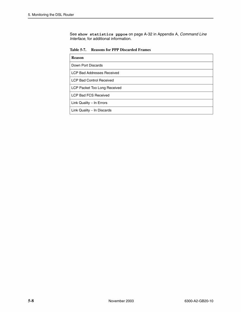
5. Monitoring the DSL Router
5-8 November 2003 6300-A2-GB20-10
See show statistics pppoe on page A-32 in Appendix A, Command Line Interface, for additional information.
Table 5-7. Reasons for PPP Discarded Frames
Reason
Down Port Discards
LCP Bad Addresses Received
LCP Bad Control Received
LCP Packet Too Long Received
LCP Bad FCS Received
Link Quality − In Errors
Link Quality − In Discards
6300-A2-GB20-10 November 2003 6-1
6Diagnostics and Troubleshooting
Diagnostics and Troubleshooting Overview
Several features are available to assist you in evaluating the Hotwire DSL Router. The following sections are covered in this chapter:
� Device Restart
� Alarms Inquiry
� System Log on page 6-2
� Ping on page 6-5
� TraceRoute on page 6-7
Device RestartThe DSL router can be restarted locally or remotely. From the CLI, type Restart and press Enter.
The router reinitializes itself, performing a power-on self-test and resetting the local System Log (SYSLOG).
Alarms Inquiry
The DSL router’s front panel includes an Alarm (ALM) LED to alert you to alarm conditions. The alarm(s) detected can be viewed using the show alarms CLI command.
See show alarms on page A-24 in Appendix A, Command Line Interface, for information about the command and what is displayed when the command is entered.
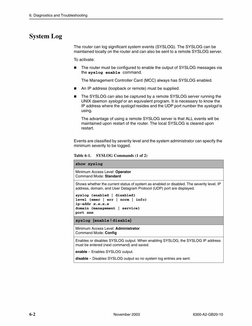
6. Diagnostics and Troubleshooting
6-2 November 2003 6300-A2-GB20-10
System Log
The router can log significant system events (SYSLOG). The SYSLOG can be maintained locally on the router and can also be sent to a remote SYSLOG server.
To activate:
� The router must be configured to enable the output of SYSLOG messages via the syslog enable command.
The Management Controller Card (MCC) always has SYSLOG enabled.
� An IP address (loopback or remote) must be supplied.
� The SYSLOG can also be captured by a remote SYSLOG server running the UNIX daemon syslogd or an equivalent program. It is necessary to know the IP address where the syslogd resides and the UDP port number the syslogd is using.
The advantage of using a remote SYSLOG server is that ALL events will be maintained upon restart of the router. The local SYSLOG is cleared upon restart.
Events are classified by severity level and the system administrator can specify the minimum severity to be logged.
Table 6-1. SYSLOG Commands (1 of 2)
show syslog
Minimum Access Level: OperatorCommand Mode: Standard
Shows whether the current status of system as enabled or disabled. The severity level, IP address, domain, and User Datagram Protocol (UDP) port are displayed.
syslog {enabled | disabled}level {emer | err | norm | info}ip-addr x.x.x.xdomain {management | service}port nnn
syslog {enable | disable}
Minimum Access Level: AdministratorCommand Mode: Config
Enables or disables SYSLOG output. When enabling SYSLOG, the SYSLOG IP address must be entered (next command) and saved.
enable – Enables SYSLOG output.
disable – Disables SYSLOG output so no system log entries are sent.
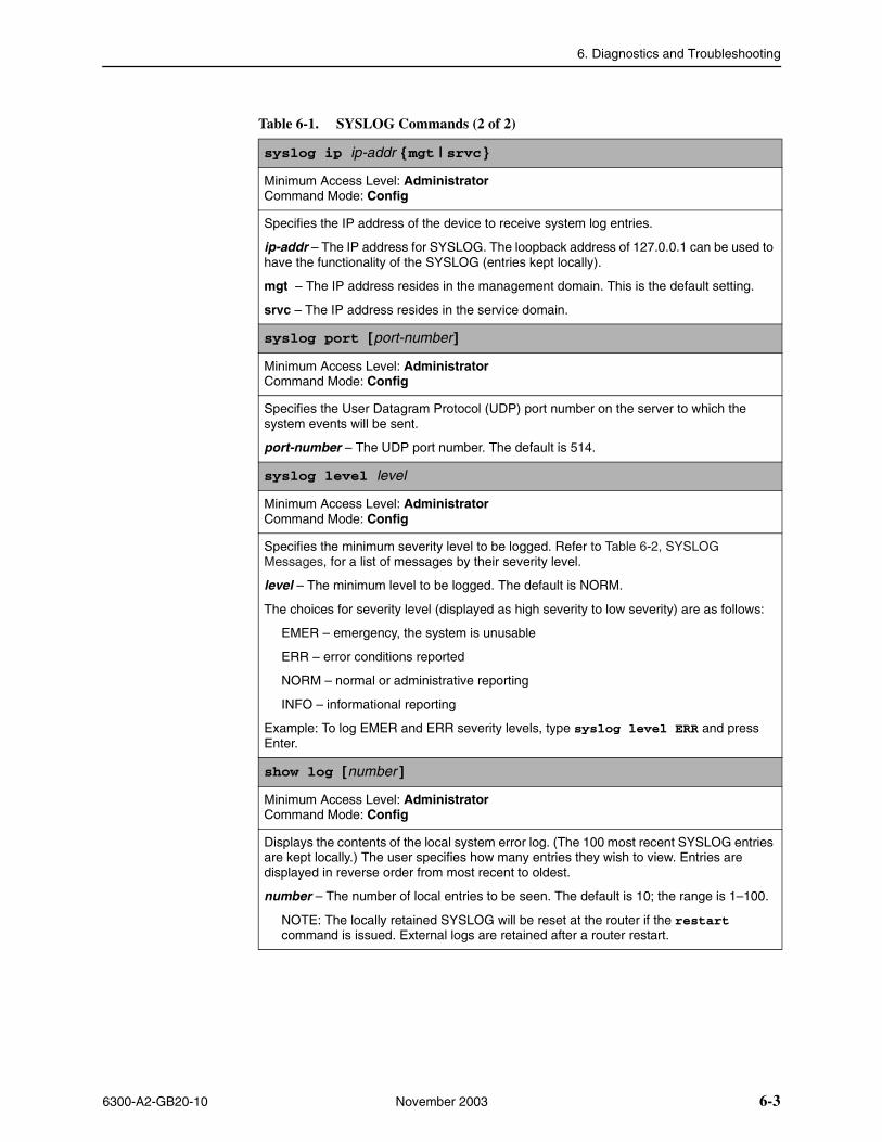
6. Diagnostics and Troubleshooting
6300-A2-GB20-10 November 2003 6-3
syslog ip ip-addr {mgt | srvc }
Minimum Access Level: AdministratorCommand Mode: Config
Specifies the IP address of the device to receive system log entries.
ip-addr – The IP address for SYSLOG. The loopback address of 127.0.0.1 can be used to have the functionality of the SYSLOG (entries kept locally).
mgt – The IP address resides in the management domain. This is the default setting.
srvc – The IP address resides in the service domain.
syslog port [port-number]
Minimum Access Level: AdministratorCommand Mode: Config
Specifies the User Datagram Protocol (UDP) port number on the server to which the system events will be sent.
port-number – The UDP port number. The default is 514.
syslog level level
Minimum Access Level: AdministratorCommand Mode: Config
Specifies the minimum severity level to be logged. Refer to Table 6-2, SYSLOG Messages, for a list of messages by their severity level.
level – The minimum level to be logged. The default is NORM.
The choices for severity level (displayed as high severity to low severity) are as follows:
EMER – emergency, the system is unusable
ERR – error conditions reported
NORM – normal or administrative reporting
INFO – informational reporting
Example: To log EMER and ERR severity levels, type syslog level ERR and press Enter.
show log [number ]
Minimum Access Level: AdministratorCommand Mode: Config
Displays the contents of the local system error log. (The 100 most recent SYSLOG entries are kept locally.) The user specifies how many entries they wish to view. Entries are displayed in reverse order from most recent to oldest.
number – The number of local entries to be seen. The default is 10; the range is 1–100.
NOTE: The locally retained SYSLOG will be reset at the router if the restart command is issued. External logs are retained after a router restart.
Table 6-1. SYSLOG Commands (2 of 2)
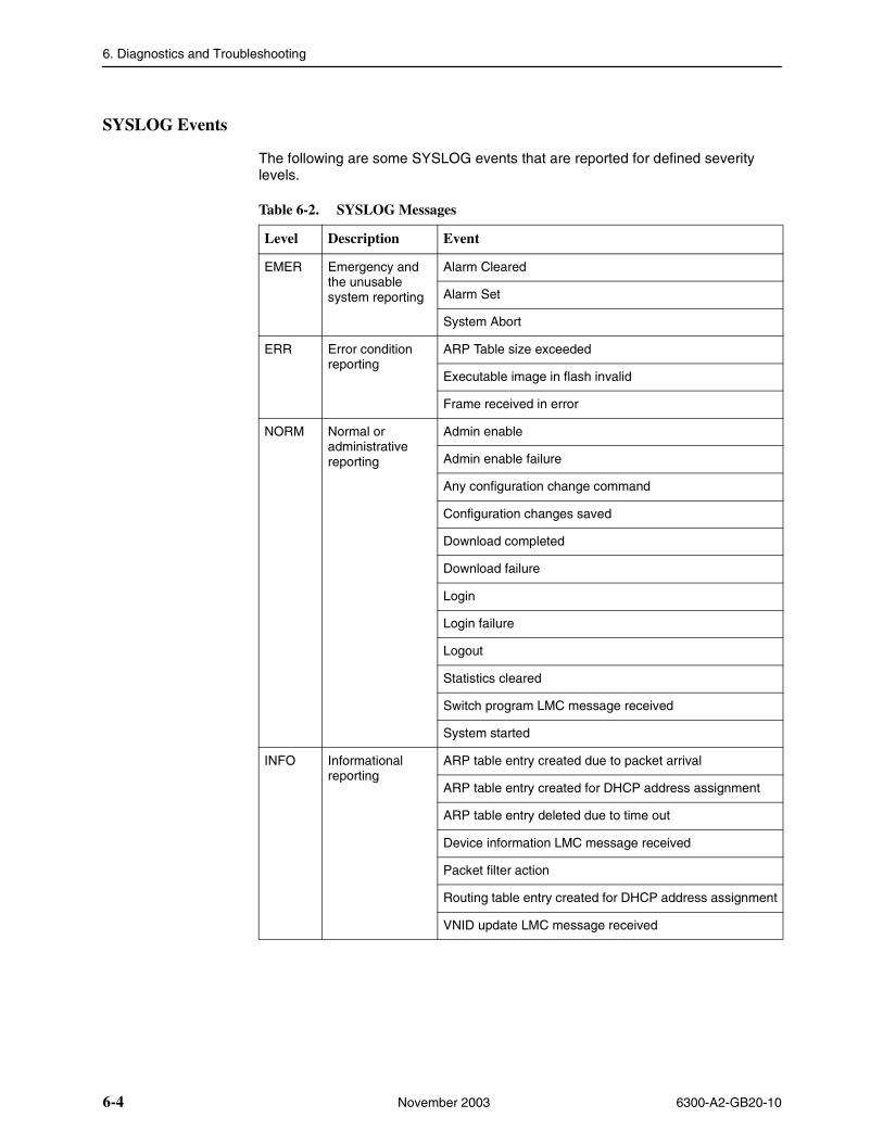
6. Diagnostics and Troubleshooting
6-4 November 2003 6300-A2-GB20-10
SYSLOG Events
The following are some SYSLOG events that are reported for defined severity levels.
Table 6-2. SYSLOG Messages
Level Description Event
EMER Emergency and the unusable system reporting
Alarm Cleared
Alarm Set
System Abort
ERR Error condition reporting
ARP Table size exceeded
Executable image in flash invalid
Frame received in error
NORM Normal or administrative reporting
Admin enable
Admin enable failure
Any configuration change command
Configuration changes saved
Download completed
Download failure
Login
Login failure
Logout
Statistics cleared
Switch program LMC message received
System started
INFO Informational reporting
ARP table entry created due to packet arrival
ARP table entry created for DHCP address assignment
ARP table entry deleted due to time out
Device information LMC message received
Packet filter action
Routing table entry created for DHCP address assignment
VNID update LMC message received
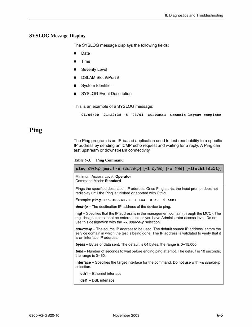
6. Diagnostics and Troubleshooting
6300-A2-GB20-10 November 2003 6-5
SYSLOG Message Display
The SYSLOG message displays the following fields:
� Date
� Time
� Severity Level
� DSLAM Slot #/Port #
� System Identifier
� SYSLOG Event Description
This is an example of a SYSLOG message:
01/06/00 21:22:38 5 03/01 CUSTOMER Console logout complete
Ping
The Ping program is an IP-based application used to test reachability to a specific IP address by sending an ICMP echo request and waiting for a reply. A Ping can test upstream or downstream connectivity.
Table 6-3. Ping Command
ping dest-ip [mgt | -x source-ip] [-l bytes] [-w time] [-i{eth1 | dsl1}]
Minimum Access Level: OperatorCommand Mode: Standard
Pings the specified destination IP address. Once Ping starts, the input prompt does not redisplay until the Ping is finished or aborted with Ctrl-c.
Example: ping 135.300.41.8 –l 144 –w 30 -i eth1
dest-ip – The destination IP address of the device to ping.
mgt – Specifies that the IP address is in the management domain (through the MCC). The mgt designation cannot be entered unless you have Administrator access level. Do not use this designation with the –x source-ip selection.
source-ip – The source IP address to be used. The default source IP address is from the service domain in which the test is being done. The IP address is validated to verify that it is an interface IP address.
bytes – Bytes of data sent. The default is 64 bytes; the range is 0–15,000.
time – Number of seconds to wait before ending ping attempt. The default is 10 seconds; the range is 0–60.
interface – Specifies the target interface for the command. Do not use with –x source-ip selection.
eth1 – Ethernet interface
dsl1 – DSL interface
6. Diagnostics and Troubleshooting
6-6 November 2003 6300-A2-GB20-10
Ping Test Results
Ping test results display in the following formats.
� For a successful Ping:
Ping reply from [x.x.x.x]: bytes of data=nn
Where nn is the number of bytes of data.
� For a timeout:
Ping reply from [x.x.x.x]: REQUEST TIMED OUT
� For an ICMP echo response of an unreachable destination:
Ping reply from [x.x.x.x]: DESTINATION UNREACHABLE

6. Diagnostics and Troubleshooting
6300-A2-GB20-10 November 2003 6-7
TraceRoute
The TraceRoute program is an IP diagnostic tool that allows you to learn the path a packet takes from the service domain local host to its remote host.
If you are unable to ping a device in a Hotwire network configuration, you may want to run a TraceRoute to identify the link (destinations up to 64 hops) between the router and the device that is not forwarding the Ping message.
Table 6-4. TraceRoute Command
traceroute dest-ip [-x source-ip] [-l bytes] [-w time] [-h hops] [-i { eth1 ����dsl1 } ]
Minimum Access Level: OperatorCommand Mode: Standard
Performs TraceRoute to the specified destination IP address. Once TraceRoute starts, the input prompt will not redisplay until TraceRoute finishes or is aborted with Ctrl-c.
Example: traceroute 135.300.41.8 –w 60 -i eth1
dest-ip – The destination IP address for TraceRoute.
source-ip – The source IP address used. The default source address is from the service domain in which the test is being done. The IP address is validated to verify that it is an interface IP address.
bytes – Bytes of data (l = length). The default is 64 bytes; the range is 0–15,000.
time – Time (in seconds) before the TraceRoute is abandoned. The default is 10 seconds; the range is 0–60.
hops – Decimal number that specifies the maximum number of hops to be tested. The default is 8; the range is 0–128.
interface – Specifies the target interface for the command. Do not use with the –x source-ip selection.
eth1 – Ethernet interface
dsl1 – DSL interface
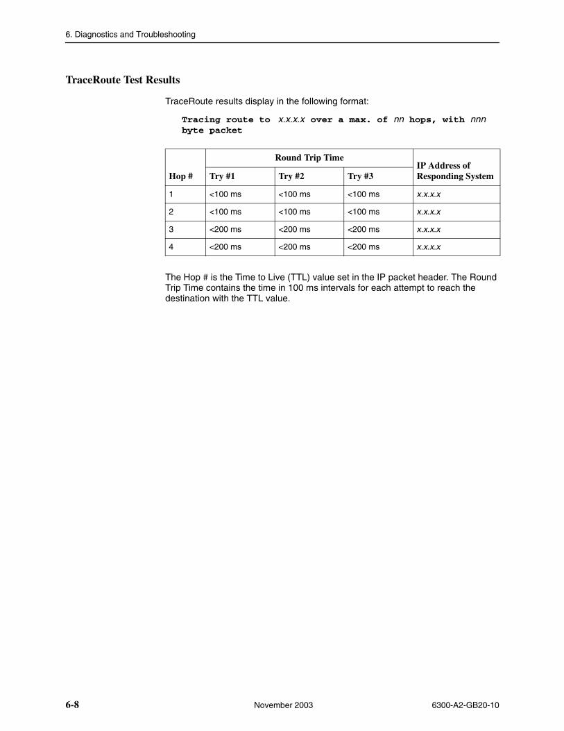
6. Diagnostics and Troubleshooting
6-8 November 2003 6300-A2-GB20-10
TraceRoute Test Results
TraceRoute results display in the following format:
Tracing route to x.x.x.x over a max. of nn hops, with nnn byte packet
The Hop # is the Time to Live (TTL) value set in the IP packet header. The Round Trip Time contains the time in 100 ms intervals for each attempt to reach the destination with the TTL value.
Hop #
Round Trip Time IP Address of Responding SystemTry #1 Try #2 Try #3
1 <100 ms <100 ms <100 ms x.x.x.x
2 <100 ms <100 ms <100 ms x.x.x.x
3 <200 ms <200 ms <200 ms x.x.x.x
4 <200 ms <200 ms <200 ms x.x.x.x
6300-A2-GB20-10 November 2003 A-1
ACommand Line Interface
Command Line Interface Capability
The Hotwire DSL router is managed with text commands from the Command Line Interface (CLI). The CLI can be accessed:
� Locally with an ASCII terminal connected to the Console port, or
� Remotely via a Telnet session (through the management interface or from the service domain).
The CLI is ASCII character-based and provides the capability to:
� Display the syntax of commands.
� Change the operational characteristics of the router by setting configuration values.
� Restore all configuration values to the initial factory default settings.
� Display the router’s hardware and identification information.
� Display system status, including DSL link and Ethernet status.
� Display a sequence of commands that will set all configurable parameters to their current value.
Refer to Appendix B, Configuration Defaults and Command Line Shortcuts.
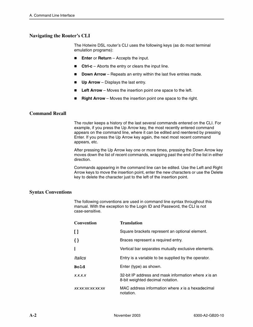
A. Command Line Interface
A-2 November 2003 6300-A2-GB20-10
Navigating the Router’s CLI
The Hotwire DSL router’s CLI uses the following keys (as do most terminal emulation programs):
� Enter or Return – Accepts the input.
� Ctrl-c – Aborts the entry or clears the input line.
� Down Arrow – Repeats an entry within the last five entries made.
� Up Arrow – Displays the last entry.
� Left Arrow – Moves the insertion point one space to the left.
� Right Arrow – Moves the insertion point one space to the right.
Command Recall
The router keeps a history of the last several commands entered on the CLI. For example, if you press the Up Arrow key, the most recently entered command appears on the command line, where it can be edited and reentered by pressing Enter. If you press the Up Arrow key again, the next most recent command appears, etc.
After pressing the Up Arrow key one or more times, pressing the Down Arrow key moves down the list of recent commands, wrapping past the end of the list in either direction.
Commands appearing in the command line can be edited. Use the Left and Right Arrow keys to move the insertion point, enter the new characters or use the Delete key to delete the character just to the left of the insertion point.
Syntax Conventions
The following conventions are used in command line syntax throughout this manual. With the exception to the Login ID and Password, the CLI is not case-sensitive.
Convention Translation
[ ] Square brackets represent an optional element.
{ } Braces represent a required entry.
| Vertical bar separates mutually exclusive elements.
Italics Entry is a variable to be supplied by the operator.
Bold Enter (type) as shown.
x.x.x.x 32-bit IP address and mask information where x is an 8-bit weighted decimal notation.
xx:xx:xx:xx:xx:xx MAC address information where x is a hexadecimal notation.
A. Command Line Interface
6300-A2-GB20-10 November 2003 A-3
CLI Commands
The following types of commands are included in this section:
� Configuration Commands on page A-4
� RFC 1483 Encapsulation Command on page A-5
� Ethernet Frame Format Command on page A-5
� Interface and Service Domain IP Address Commands on page A-6
� IP Routing Commands on page A-7
� Bridge Commands on page A-8
� ARP Commands on page A-9
� Proxy ARP Command on page A-10
� NAT Commands on page A-11
� DHCP Server Commands on page A-14
� DHCP Relay Agent Commands on page A-16
� IP Packet Processing Commands on page A-17
� PPPoE Client Commands on page A-18
� Telnet Commands on page A-21
� Traps Command on page A-23
� Clearing Statistics Command on page A-23
� Show Commands on page A-24
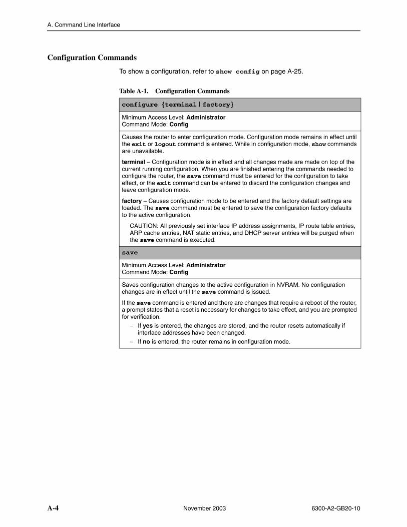
A. Command Line Interface
A-4 November 2003 6300-A2-GB20-10
Configuration Commands
To show a configuration, refer to show config on page A-25.
Table A-1. Configuration Commands
configure {terminal | factory}
Minimum Access Level: AdministratorCommand Mode: Config
Causes the router to enter configuration mode. Configuration mode remains in effect until the exit or logout command is entered. While in configuration mode, show commands are unavailable.
terminal – Configuration mode is in effect and all changes made are made on top of the current running configuration. When you are finished entering the commands needed to configure the router, the save command must be entered for the configuration to take effect, or the exit command can be entered to discard the configuration changes and leave configuration mode.
factory – Causes configuration mode to be entered and the factory default settings are loaded. The save command must be entered to save the configuration factory defaults to the active configuration.
CAUTION: All previously set interface IP address assignments, IP route table entries, ARP cache entries, NAT static entries, and DHCP server entries will be purged when the save command is executed.
save
Minimum Access Level: AdministratorCommand Mode: Config
Saves configuration changes to the active configuration in NVRAM. No configuration changes are in effect until the save command is issued.
If the save command is entered and there are changes that require a reboot of the router, a prompt states that a reset is necessary for changes to take effect, and you are prompted for verification.
– If yes is entered, the changes are stored, and the router resets automatically if interface addresses have been changed.
– If no is entered, the router remains in configuration mode.
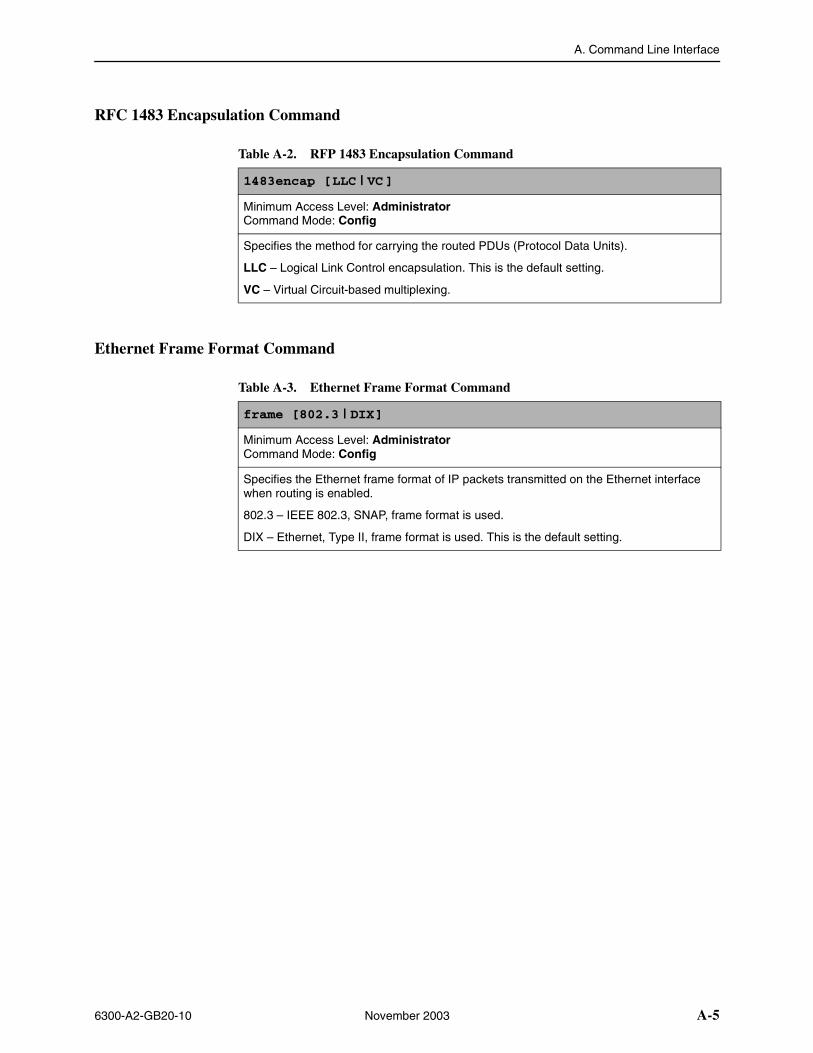
A. Command Line Interface
6300-A2-GB20-10 November 2003 A-5
RFC 1483 Encapsulation Command
Ethernet Frame Format Command
Table A-2. RFP 1483 Encapsulation Command
1483encap [LLC | VC]
Minimum Access Level: AdministratorCommand Mode: Config
Specifies the method for carrying the routed PDUs (Protocol Data Units).
LLC – Logical Link Control encapsulation. This is the default setting.
VC – Virtual Circuit-based multiplexing.
Table A-3. Ethernet Frame Format Command
frame [802.3 | DIX]
Minimum Access Level: AdministratorCommand Mode: Config
Specifies the Ethernet frame format of IP packets transmitted on the Ethernet interface when routing is enabled.
802.3 – IEEE 802.3, SNAP, frame format is used.
DIX – Ethernet, Type II, frame format is used. This is the default setting.
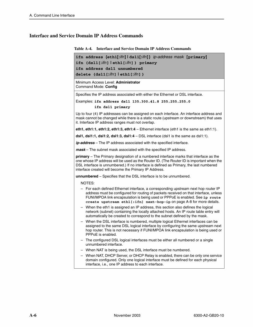
A. Command Line Interface
A-6 November 2003 6300-A2-GB20-10
Interface and Service Domain IP Address Commands
Table A-4. Interface and Service Domain IP Address Commands
ifn address {eth1[:ifn] | dsl1[:ifn] } ip-address mask [primary]ifn {dsl1[:ifn] | eth1[:ifn]} primaryifn address dsl1 unnumbered
delete {dsl1[:ifn] | eth1[:ifn]}
Minimum Access Level: AdministratorCommand Mode: Config
Specifies the IP address associated with either the Ethernet or DSL interface.
Examples: ifn address dsl1 135.300.41.8 255.255.255.0
ifn dsl1 primary
Up to four (4) IP addresses can be assigned on each interface. An interface address and mask cannot be changed while there is a static route (upstream or downstream) that uses it. Interface IP address ranges must not overlap.
eth1, eth1:1, eth1:2, eth1:3, eth1:4 – Ethernet interface (eth1 is the same as eth1:1).
dsl1, dsl1:1, dsl1:2, dsl1:3, dsl1:4 – DSL interface (dsl1 is the same as dsl1:1).
ip-address – The IP address associated with the specified interface.
mask – The subnet mask associated with the specified IP address.
primary – The Primary designation of a numbered interface marks that interface as the one whose IP address will be used as the Router ID. (The Router ID is important when the DSL interface is unnumbered.) If no interface is defined as Primary, the last numbered interface created will become the Primary IP Address.
unnumbered – Specifies that the DSL interface is to be unnumbered.
NOTES:
– For each defined Ethernet interface, a corresponding upstream next hop router IP address must be configured for routing of packets received on that interface, unless FUNI/MPOA link encapsulation is being used or PPPoE is enabled. See ip route create upstream eth1[:ifn] next-hop-ip on page A-8 for more details.
– When the eth1 is assigned an IP address, this section also defines the logical network (subnet) containing the locally attached hosts. An IP route table entry will automatically be created to correspond to the subnet defined by the mask.
– When the DSL interface is numbered, multiple logical Ethernet interfaces can be assigned to the same DSL logical interface by configuring the same upstream next hop router. This is not necessary if FUNI/MPOA link encapsulation is being used or PPPoE is enabled.
– The configured DSL logical interfaces must be either all numbered or a single unnumbered interface.
– When NAT is being used, the DSL interface must be numbered.
– When NAT, DHCP Server, or DHCP Relay is enabled, there can be only one service domain configured. Only one logical interface must be defined for each physical interface, i.e., one IP address to each interface.
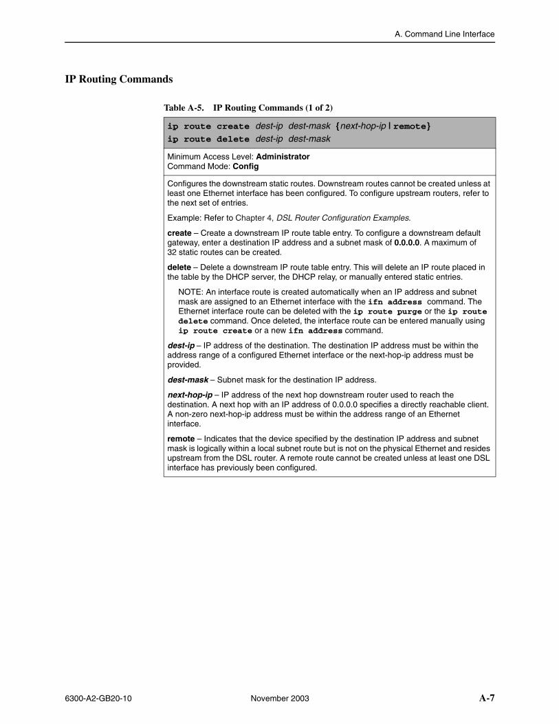
A. Command Line Interface
6300-A2-GB20-10 November 2003 A-7
IP Routing Commands
Table A-5. IP Routing Commands (1 of 2)
ip route create dest-ip dest-mask {next-hop-ip | remote}ip route delete dest-ip dest-mask
Minimum Access Level: AdministratorCommand Mode: Config
Configures the downstream static routes. Downstream routes cannot be created unless at least one Ethernet interface has been configured. To configure upstream routers, refer to the next set of entries.
Example: Refer to Chapter 4, DSL Router Configuration Examples.
create – Create a downstream IP route table entry. To configure a downstream default gateway, enter a destination IP address and a subnet mask of 0.0.0.0. A maximum of 32 static routes can be created.
delete – Delete a downstream IP route table entry. This will delete an IP route placed in the table by the DHCP server, the DHCP relay, or manually entered static entries.
NOTE: An interface route is created automatically when an IP address and subnet mask are assigned to an Ethernet interface with the ifn address command. The Ethernet interface route can be deleted with the ip route purge or the ip route delete command. Once deleted, the interface route can be entered manually using ip route create or a new ifn address command.
dest-ip – IP address of the destination. The destination IP address must be within the address range of a configured Ethernet interface or the next-hop-ip address must be provided.
dest-mask – Subnet mask for the destination IP address.
next-hop-ip – IP address of the next hop downstream router used to reach the destination. A next hop with an IP address of 0.0.0.0 specifies a directly reachable client. A non-zero next-hop-ip address must be within the address range of an Ethernet interface.
remote – Indicates that the device specified by the destination IP address and subnet mask is logically within a local subnet route but is not on the physical Ethernet and resides upstream from the DSL router. A remote route cannot be created unless at least one DSL interface has previously been configured.
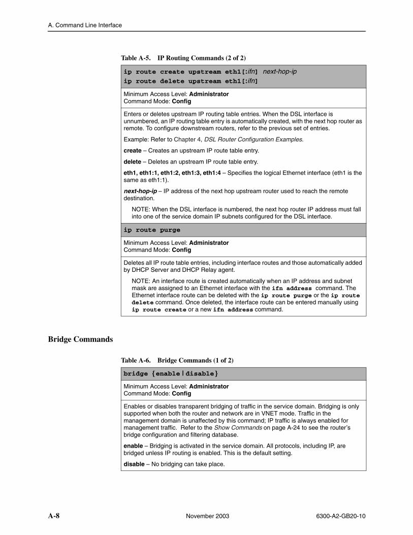
A. Command Line Interface
A-8 November 2003 6300-A2-GB20-10
Bridge Commands
ip route create upstream eth1[:ifn] next-hop-ipip route delete upstream eth1[:ifn]
Minimum Access Level: AdministratorCommand Mode: Config
Enters or deletes upstream IP routing table entries. When the DSL interface is unnumbered, an IP routing table entry is automatically created, with the next hop router as remote. To configure downstream routers, refer to the previous set of entries.
Example: Refer to Chapter 4, DSL Router Configuration Examples.
create – Creates an upstream IP route table entry.
delete – Deletes an upstream IP route table entry.
eth1, eth1:1, eth1:2, eth1:3, eth1:4 – Specifies the logical Ethernet interface (eth1 is the same as eth1:1).
next-hop-ip – IP address of the next hop upstream router used to reach the remote destination.
NOTE: When the DSL interface is numbered, the next hop router IP address must fall into one of the service domain IP subnets configured for the DSL interface.
ip route purge
Minimum Access Level: AdministratorCommand Mode: Config
Deletes all IP route table entries, including interface routes and those automatically added by DHCP Server and DHCP Relay agent.
NOTE: An interface route is created automatically when an IP address and subnet mask are assigned to an Ethernet interface with the ifn address command. The Ethernet interface route can be deleted with the ip route purge or the ip route delete command. Once deleted, the interface route can be entered manually using ip route create or a new ifn address command.
Table A-5. IP Routing Commands (2 of 2)
Table A-6. Bridge Commands (1 of 2)
bridge {enable | disable }
Minimum Access Level: AdministratorCommand Mode: Config
Enables or disables transparent bridging of traffic in the service domain. Bridging is only supported when both the router and network are in VNET mode. Traffic in the management domain is unaffected by this command; IP traffic is always enabled for management traffic. Refer to the Show Commands on page A-24 to see the router’s bridge configuration and filtering database.
enable – Bridging is activated in the service domain. All protocols, including IP, are bridged unless IP routing is enabled. This is the default setting.
disable – No bridging can take place.
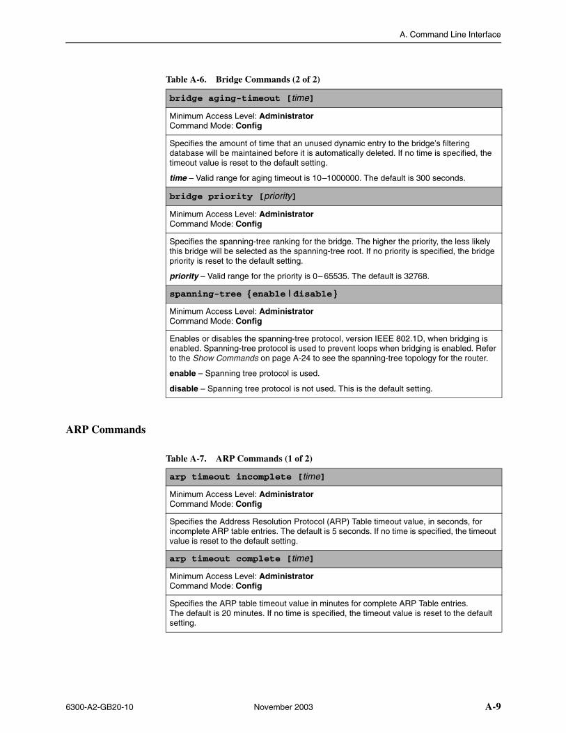
A. Command Line Interface
6300-A2-GB20-10 November 2003 A-9
ARP Commands
bridge aging-timeout [time]
Minimum Access Level: AdministratorCommand Mode: Config
Specifies the amount of time that an unused dynamic entry to the bridge’s filtering database will be maintained before it is automatically deleted. If no time is specified, the timeout value is reset to the default setting.
time – Valid range for aging timeout is 10–1000000. The default is 300 seconds.
bridge priority [priority]
Minimum Access Level: AdministratorCommand Mode: Config
Specifies the spanning-tree ranking for the bridge. The higher the priority, the less likely this bridge will be selected as the spanning-tree root. If no priority is specified, the bridge priority is reset to the default setting.
priority – Valid range for the priority is 0– 65535. The default is 32768.
spanning-tree {enable | disable }
Minimum Access Level: AdministratorCommand Mode: Config
Enables or disables the spanning-tree protocol, version IEEE 802.1D, when bridging is enabled. Spanning-tree protocol is used to prevent loops when bridging is enabled. Refer to the Show Commands on page A-24 to see the spanning-tree topology for the router.
enable – Spanning tree protocol is used.
disable – Spanning tree protocol is not used. This is the default setting.
Table A-6. Bridge Commands (2 of 2)
Table A-7. ARP Commands (1 of 2)
arp timeout incomplete [time]
Minimum Access Level: AdministratorCommand Mode: Config
Specifies the Address Resolution Protocol (ARP) Table timeout value, in seconds, for incomplete ARP table entries. The default is 5 seconds. If no time is specified, the timeout value is reset to the default setting.
arp timeout complete [time]
Minimum Access Level: AdministratorCommand Mode: Config
Specifies the ARP table timeout value in minutes for complete ARP Table entries. The default is 20 minutes. If no time is specified, the timeout value is reset to the default setting.
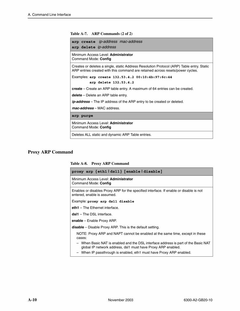
A. Command Line Interface
A-10 November 2003 6300-A2-GB20-10
Proxy ARP Command
arp create ip-address mac-addressarp delete ip-address
Minimum Access Level: AdministratorCommand Mode: Config
Creates or deletes a single, static Address Resolution Protocol (ARP) Table entry. Static ARP entries created with this command are retained across resets/power cycles.
Examples: arp create 132.53.4.2 00:10:4b:97:6c:44
arp delete 132.53.4.2
create – Create an ARP table entry. A maximum of 64 entries can be created.
delete – Delete an ARP table entry.
ip-address – The IP address of the ARP entry to be created or deleted.
mac-address – MAC address.
arp purge
Minimum Access Level: AdministratorCommand Mode: Config
Deletes ALL static and dynamic ARP Table entries.
Table A-7. ARP Commands (2 of 2)
Table A-8. Proxy ARP Command
proxy arp {eth1 | dsl1 } [enable | disable ]
Minimum Access Level: AdministratorCommand Mode: Config
Enables or disables Proxy ARP for the specified interface. If enable or disable is not entered, enable is assumed.
Example: proxy arp dsl1 disable
eth1 – The Ethernet interface.
dsl1 – The DSL interface.
enable – Enable Proxy ARP.
disable – Disable Proxy ARP. This is the default setting.
NOTE: Proxy ARP and NAPT cannot be enabled at the same time, except in these cases:
– When Basic NAT is enabled and the DSL interface address is part of the Basic NAT global IP network address, dsl1 must have Proxy ARP enabled.
– When IP passthrough is enabled, eth1 must have Proxy ARP enabled.
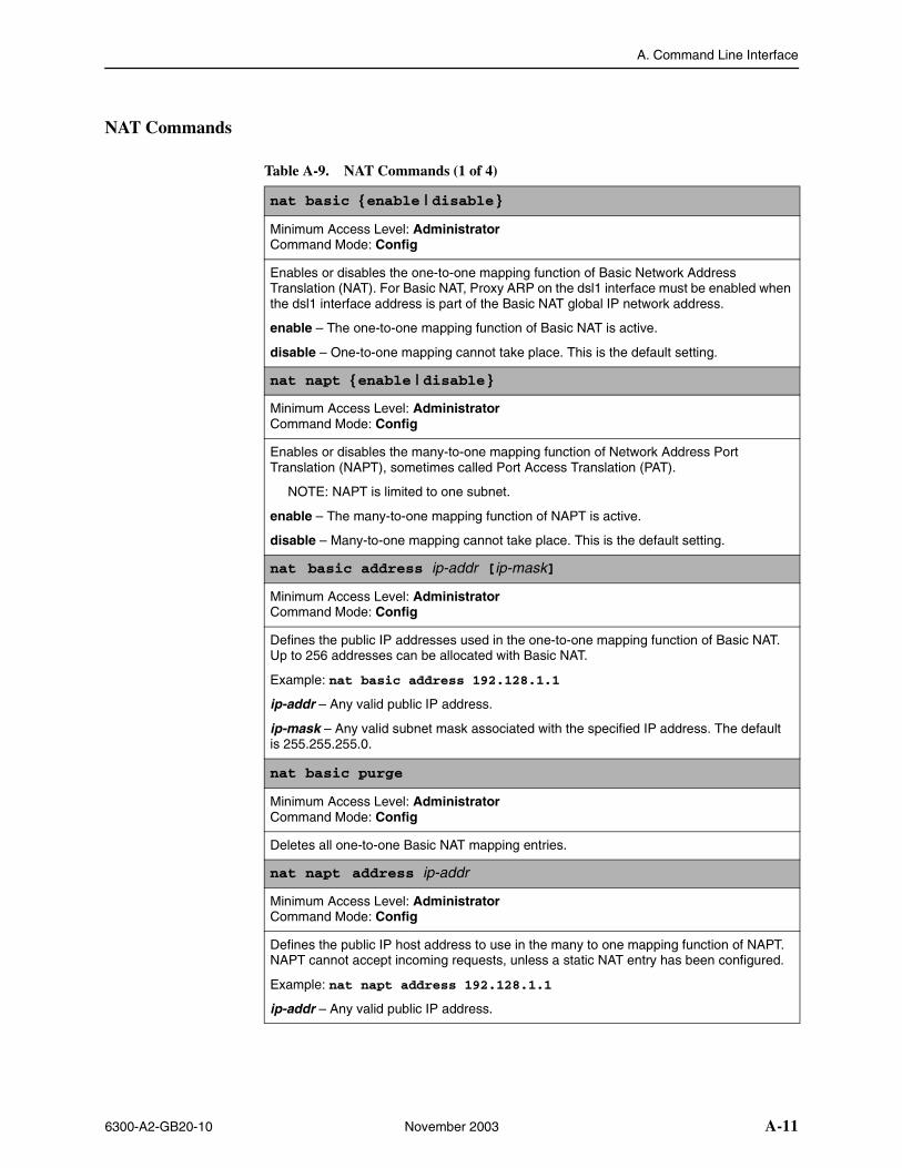
A. Command Line Interface
6300-A2-GB20-10 November 2003 A-11
NAT Commands
Table A-9. NAT Commands (1 of 4)
nat basic {enable | disable }
Minimum Access Level: AdministratorCommand Mode: Config
Enables or disables the one-to-one mapping function of Basic Network Address Translation (NAT). For Basic NAT, Proxy ARP on the dsl1 interface must be enabled when the dsl1 interface address is part of the Basic NAT global IP network address.
enable – The one-to-one mapping function of Basic NAT is active.
disable – One-to-one mapping cannot take place. This is the default setting.
nat napt {enable | disable }
Minimum Access Level: AdministratorCommand Mode: Config
Enables or disables the many-to-one mapping function of Network Address Port Translation (NAPT), sometimes called Port Access Translation (PAT).
NOTE: NAPT is limited to one subnet.
enable – The many-to-one mapping function of NAPT is active.
disable – Many-to-one mapping cannot take place. This is the default setting.
nat basic address ip-addr [ip-mask]
Minimum Access Level: AdministratorCommand Mode: Config
Defines the public IP addresses used in the one-to-one mapping function of Basic NAT. Up to 256 addresses can be allocated with Basic NAT.
Example: nat basic address 192.128.1.1
ip-addr – Any valid public IP address.
ip-mask – Any valid subnet mask associated with the specified IP address. The default is 255.255.255.0.
nat basic purge
Minimum Access Level: AdministratorCommand Mode: Config
Deletes all one-to-one Basic NAT mapping entries.
nat napt address ip-addr
Minimum Access Level: AdministratorCommand Mode: Config
Defines the public IP host address to use in the many to one mapping function of NAPT. NAPT cannot accept incoming requests, unless a static NAT entry has been configured.
Example: nat napt address 192.128.1.1
ip-addr – Any valid public IP address.
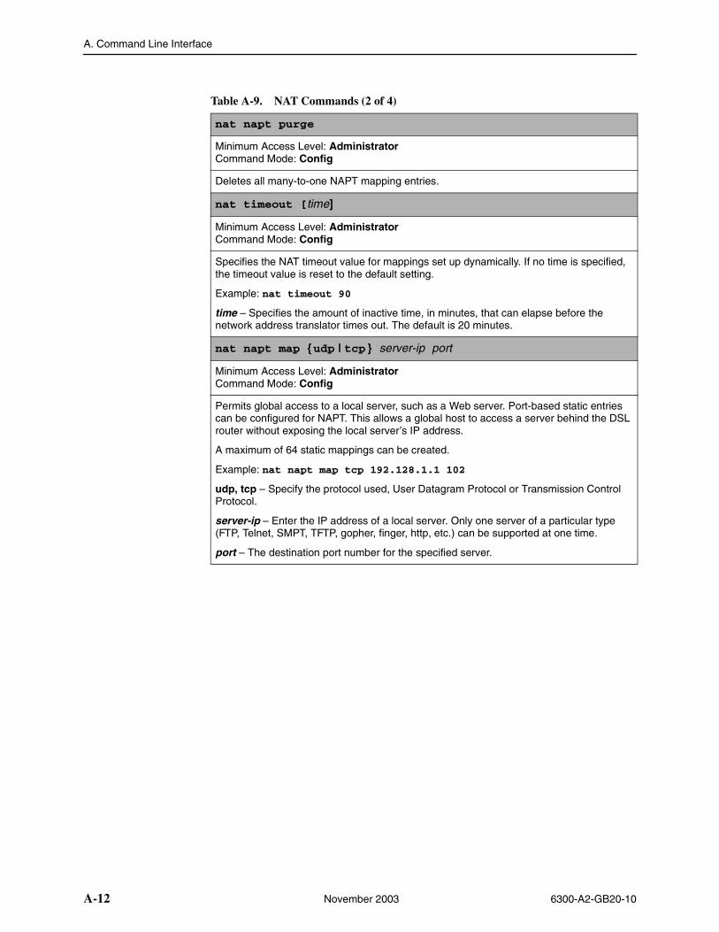
A. Command Line Interface
A-12 November 2003 6300-A2-GB20-10
nat napt purge
Minimum Access Level: AdministratorCommand Mode: Config
Deletes all many-to-one NAPT mapping entries.
nat timeout [time]
Minimum Access Level: AdministratorCommand Mode: Config
Specifies the NAT timeout value for mappings set up dynamically. If no time is specified, the timeout value is reset to the default setting.
Example: nat timeout 90
time – Specifies the amount of inactive time, in minutes, that can elapse before the network address translator times out. The default is 20 minutes.
nat napt map {udp | tcp } server-ip port
Minimum Access Level: AdministratorCommand Mode: Config
Permits global access to a local server, such as a Web server. Port-based static entries can be configured for NAPT. This allows a global host to access a server behind the DSL router without exposing the local server’s IP address.
A maximum of 64 static mappings can be created.
Example: nat napt map tcp 192.128.1.1 102
udp, tcp – Specify the protocol used, User Datagram Protocol or Transmission Control Protocol.
server-ip – Enter the IP address of a local server. Only one server of a particular type (FTP, Telnet, SMPT, TFTP, gopher, finger, http, etc.) can be supported at one time.
port – The destination port number for the specified server.
Table A-9. NAT Commands (2 of 4)
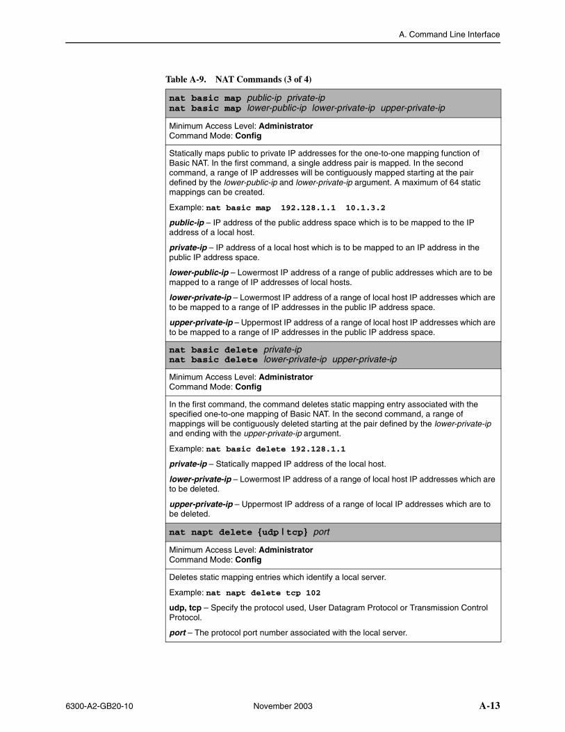
A. Command Line Interface
6300-A2-GB20-10 November 2003 A-13
nat basic map public-ip private-ip nat basic map lower-public-ip lower-private-ip upper-private-ip
Minimum Access Level: AdministratorCommand Mode: Config
Statically maps public to private IP addresses for the one-to-one mapping function of Basic NAT. In the first command, a single address pair is mapped. In the second command, a range of IP addresses will be contiguously mapped starting at the pair defined by the lower-public-ip and lower-private-ip argument. A maximum of 64 static mappings can be created.
Example: nat basic map 192.128.1.1 10.1.3.2
public-ip – IP address of the public address space which is to be mapped to the IP address of a local host.
private-ip – IP address of a local host which is to be mapped to an IP address in the public IP address space.
lower-public-ip – Lowermost IP address of a range of public addresses which are to be mapped to a range of IP addresses of local hosts.
lower-private-ip – Lowermost IP address of a range of local host IP addresses which are to be mapped to a range of IP addresses in the public IP address space.
upper-private-ip – Uppermost IP address of a range of local host IP addresses which are to be mapped to a range of IP addresses in the public IP address space.
nat basic delete private-ipnat basic delete lower-private-ip upper-private-ip
Minimum Access Level: AdministratorCommand Mode: Config
In the first command, the command deletes static mapping entry associated with the specified one-to-one mapping of Basic NAT. In the second command, a range of mappings will be contiguously deleted starting at the pair defined by the lower-private-ip and ending with the upper-private-ip argument.
Example: nat basic delete 192.128.1.1
private-ip – Statically mapped IP address of the local host.
lower-private-ip – Lowermost IP address of a range of local host IP addresses which are to be deleted.
upper-private-ip – Uppermost IP address of a range of local IP addresses which are to be deleted.
nat napt delete {udp | tcp} port
Minimum Access Level: AdministratorCommand Mode: Config
Deletes static mapping entries which identify a local server.
Example: nat napt delete tcp 102
udp, tcp – Specify the protocol used, User Datagram Protocol or Transmission Control Protocol.
port – The protocol port number associated with the local server.
Table A-9. NAT Commands (3 of 4)
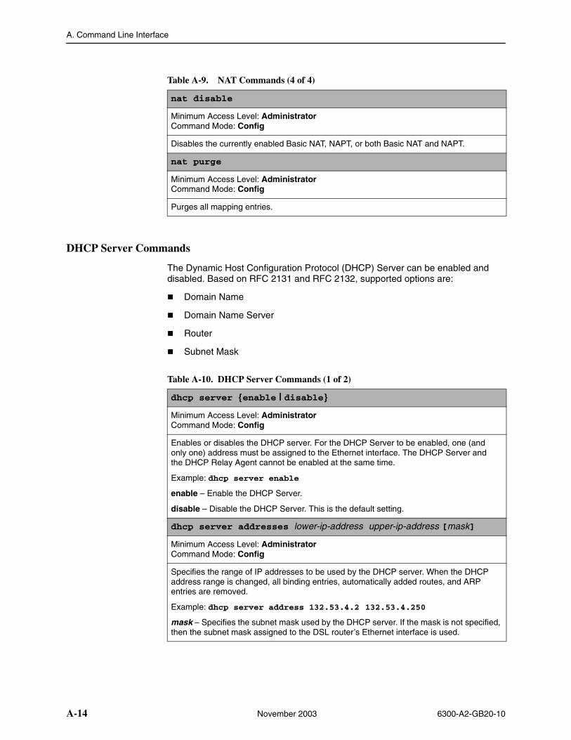
A. Command Line Interface
A-14 November 2003 6300-A2-GB20-10
DHCP Server Commands
The Dynamic Host Configuration Protocol (DHCP) Server can be enabled and disabled. Based on RFC 2131 and RFC 2132, supported options are:
� Domain Name
� Domain Name Server
� Router
� Subnet Mask
nat disable
Minimum Access Level: AdministratorCommand Mode: Config
Disables the currently enabled Basic NAT, NAPT, or both Basic NAT and NAPT.
nat purge
Minimum Access Level: AdministratorCommand Mode: Config
Purges all mapping entries.
Table A-9. NAT Commands (4 of 4)
Table A-10. DHCP Server Commands (1 of 2)
dhcp server {enable | disable}
Minimum Access Level: AdministratorCommand Mode: Config
Enables or disables the DHCP server. For the DHCP Server to be enabled, one (and only one) address must be assigned to the Ethernet interface. The DHCP Server and the DHCP Relay Agent cannot be enabled at the same time.
Example: dhcp server enable
enable – Enable the DHCP Server.
disable – Disable the DHCP Server. This is the default setting.
dhcp server addresses lower-ip-address upper-ip-address [mask]
Minimum Access Level: AdministratorCommand Mode: Config
Specifies the range of IP addresses to be used by the DHCP server. When the DHCP address range is changed, all binding entries, automatically added routes, and ARP entries are removed.
Example: dhcp server address 132.53.4.2 132.53.4.250
mask – Specifies the subnet mask used by the DHCP server. If the mask is not specified, then the subnet mask assigned to the DSL router’s Ethernet interface is used.
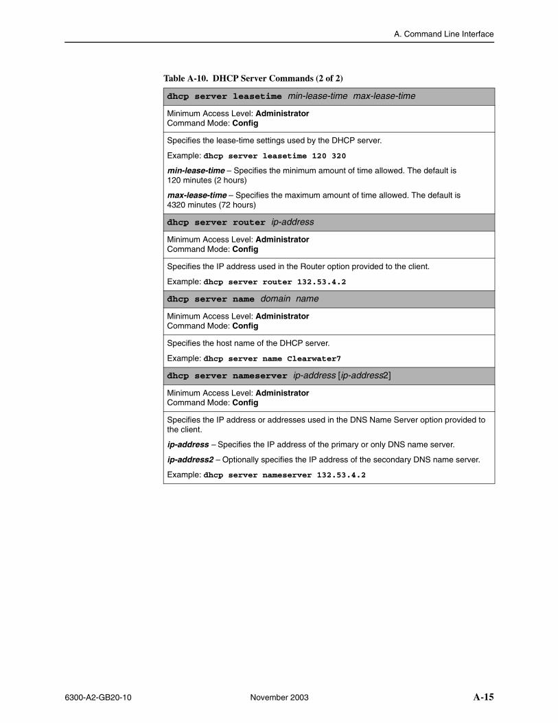
A. Command Line Interface
6300-A2-GB20-10 November 2003 A-15
dhcp server leasetime min-lease-time max-lease-time
Minimum Access Level: AdministratorCommand Mode: Config
Specifies the lease-time settings used by the DHCP server.
Example: dhcp server leasetime 120 320
min-lease-time – Specifies the minimum amount of time allowed. The default is 120 minutes (2 hours)
max-lease-time – Specifies the maximum amount of time allowed. The default is 4320 minutes (72 hours)
dhcp server router ip-address
Minimum Access Level: AdministratorCommand Mode: Config
Specifies the IP address used in the Router option provided to the client.
Example: dhcp server router 132.53.4.2
dhcp server name domain name
Minimum Access Level: AdministratorCommand Mode: Config
Specifies the host name of the DHCP server.
Example: dhcp server name Clearwater7
dhcp server nameserver ip-address [ip-address2]
Minimum Access Level: AdministratorCommand Mode: Config
Specifies the IP address or addresses used in the DNS Name Server option provided to the client.
ip-address – Specifies the IP address of the primary or only DNS name server.
ip-address2 – Optionally specifies the IP address of the secondary DNS name server.
Example: dhcp server nameserver 132.53.4.2
Table A-10. DHCP Server Commands (2 of 2)
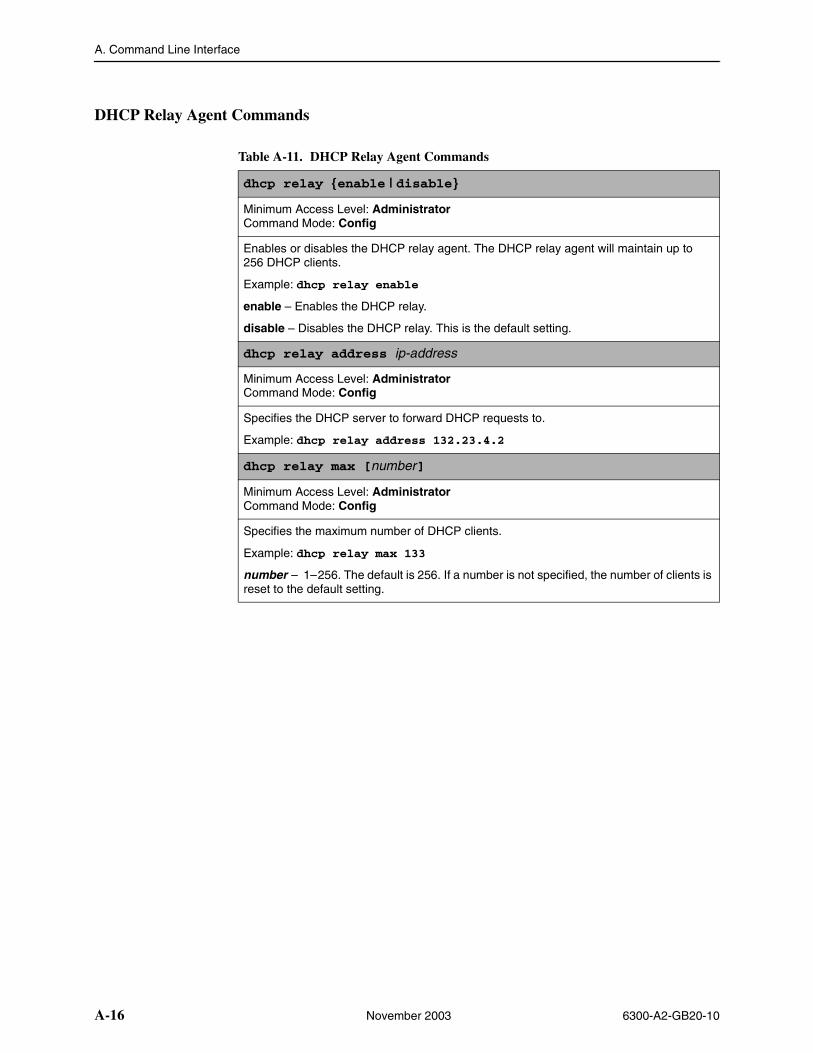
A. Command Line Interface
A-16 November 2003 6300-A2-GB20-10
DHCP Relay Agent Commands
Table A-11. DHCP Relay Agent Commands
dhcp relay {enable | disable}
Minimum Access Level: AdministratorCommand Mode: Config
Enables or disables the DHCP relay agent. The DHCP relay agent will maintain up to 256 DHCP clients.
Example: dhcp relay enable
enable – Enables the DHCP relay.
disable – Disables the DHCP relay. This is the default setting.
dhcp relay address ip-address
Minimum Access Level: AdministratorCommand Mode: Config
Specifies the DHCP server to forward DHCP requests to.
Example: dhcp relay address 132.23.4.2
dhcp relay max [number]
Minimum Access Level: AdministratorCommand Mode: Config
Specifies the maximum number of DHCP clients.
Example: dhcp relay max 133
number – 1–256. The default is 256. If a number is not specified, the number of clients is reset to the default setting.
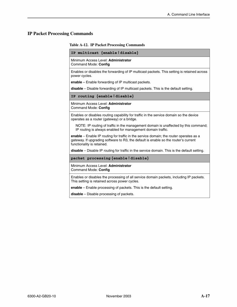
A. Command Line Interface
6300-A2-GB20-10 November 2003 A-17
IP Packet Processing Commands
Table A-12. IP Packet Processing Commands
IP multicast {enable | disable}
Minimum Access Level: AdministratorCommand Mode: Config
Enables or disables the forwarding of IP multicast packets. This setting is retained across power cycles.
enable – Enable forwarding of IP multicast packets.
disable – Disable forwarding of IP multicast packets. This is the default setting.
IP routing {enable | disable}
Minimum Access Level: AdministratorCommand Mode: Config
Enables or disables routing capability for traffic in the service domain so the device operates as a router (gateway) or a bridge.
NOTE: IP routing of traffic in the management domain is unaffected by this command; IP routing is always enabled for management domain traffic.
enable – Enable IP routing for traffic in the service domain; the router operates as a gateway. If upgrading software to R3, the default is enable so the router’s current functionality is retained.
disable – Disable IP routing for traffic in the service domain. This is the default setting.
packet processing {enable | disable}
Minimum Access Level: AdministratorCommand Mode: Config
Enables or disables the processing of all service domain packets, including IP packets. This setting is retained across power cycles.
enable – Enable processing of packets. This is the default setting.
disable – Disable processing of packets.
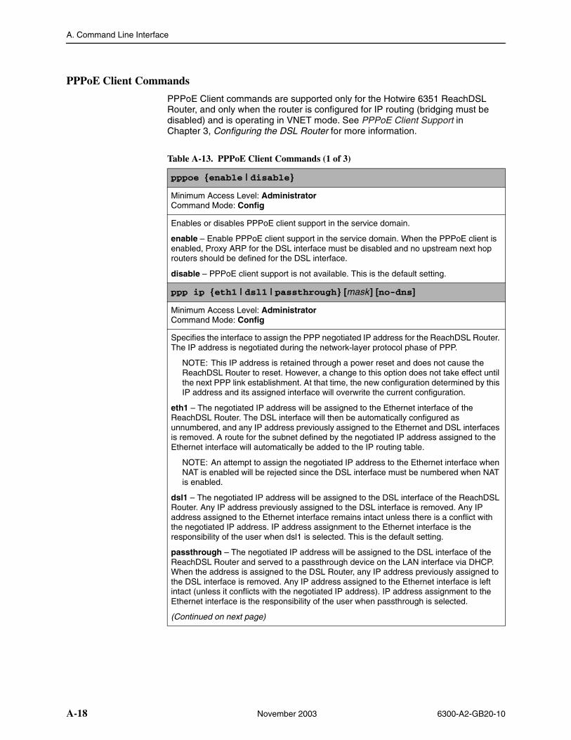
A. Command Line Interface
A-18 November 2003 6300-A2-GB20-10
PPPoE Client Commands
PPPoE Client commands are supported only for the Hotwire 6351 ReachDSL Router, and only when the router is configured for IP routing (bridging must be disabled) and is operating in VNET mode. See PPPoE Client Support in Chapter 3, Configuring the DSL Router for more information.
Table A-13. PPPoE Client Commands (1 of 3)
pppoe {enable | disable}
Minimum Access Level: AdministratorCommand Mode: Config
Enables or disables PPPoE client support in the service domain.
enable – Enable PPPoE client support in the service domain. When the PPPoE client is enabled, Proxy ARP for the DSL interface must be disabled and no upstream next hop routers should be defined for the DSL interface.
disable – PPPoE client support is not available. This is the default setting.
ppp ip {eth1 | dsl1 | passthrough} [mask] [no-dns]
Minimum Access Level: AdministratorCommand Mode: Config
Specifies the interface to assign the PPP negotiated IP address for the ReachDSL Router. The IP address is negotiated during the network-layer protocol phase of PPP.
NOTE: This IP address is retained through a power reset and does not cause the ReachDSL Router to reset. However, a change to this option does not take effect until the next PPP link establishment. At that time, the new configuration determined by this IP address and its assigned interface will overwrite the current configuration.
eth1 – The negotiated IP address will be assigned to the Ethernet interface of the ReachDSL Router. The DSL interface will then be automatically configured as unnumbered, and any IP address previously assigned to the Ethernet and DSL interfaces is removed. A route for the subnet defined by the negotiated IP address assigned to the Ethernet interface will automatically be added to the IP routing table.
NOTE: An attempt to assign the negotiated IP address to the Ethernet interface when NAT is enabled will be rejected since the DSL interface must be numbered when NAT is enabled.
dsl1 – The negotiated IP address will be assigned to the DSL interface of the ReachDSL Router. Any IP address previously assigned to the DSL interface is removed. Any IP address assigned to the Ethernet interface remains intact unless there is a conflict with the negotiated IP address. IP address assignment to the Ethernet interface is the responsibility of the user when dsl1 is selected. This is the default setting.
passthrough – The negotiated IP address will be assigned to the DSL interface of the ReachDSL Router and served to a passthrough device on the LAN interface via DHCP. When the address is assigned to the DSL Router, any IP address previously assigned to the DSL interface is removed. Any IP address assigned to the Ethernet interface is left intact (unless it conflicts with the negotiated IP address). IP address assignment to the Ethernet interface is the responsibility of the user when passthrough is selected.
(Continued on next page)
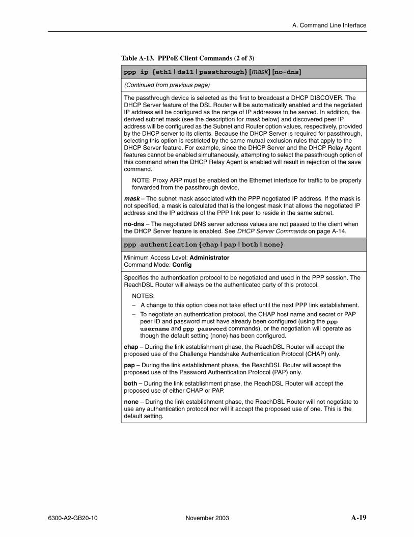
A. Command Line Interface
6300-A2-GB20-10 November 2003 A-19
ppp ip {eth1 | dsl1 | passthrough} [mask] [no-dns]
(Continued from previous page)
The passthrough device is selected as the first to broadcast a DHCP DISCOVER. The DHCP Server feature of the DSL Router will be automatically enabled and the negotiated IP address will be configured as the range of IP addresses to be served. In addition, the derived subnet mask (see the description for mask below) and discovered peer IP address will be configured as the Subnet and Router option values, respectively, provided by the DHCP server to its clients. Because the DHCP Server is required for passthrough, selecting this option is restricted by the same mutual exclusion rules that apply to the DHCP Server feature. For example, since the DHCP Server and the DHCP Relay Agent features cannot be enabled simultaneously, attempting to select the passthrough option of this command when the DHCP Relay Agent is enabled will result in rejection of the save command.
NOTE: Proxy ARP must be enabled on the Ethernet interface for traffic to be properly forwarded from the passthrough device.
mask – The subnet mask associated with the PPP negotiated IP address. If the mask is not specified, a mask is calculated that is the longest mask that allows the negotiated IP address and the IP address of the PPP link peer to reside in the same subnet.
no-dns – The negotiated DNS server address values are not passed to the client when the DHCP Server feature is enabled. See DHCP Server Commands on page A-14.
ppp authentication {chap | pap | both | none}
Minimum Access Level: AdministratorCommand Mode: Config
Specifies the authentication protocol to be negotiated and used in the PPP session. The ReachDSL Router will always be the authenticated party of this protocol.
NOTES:
– A change to this option does not take effect until the next PPP link establishment.
– To negotiate an authentication protocol, the CHAP host name and secret or PAP peer ID and password must have already been configured (using the ppp username and ppp password commands), or the negotiation will operate as though the default setting (none) has been configured.
chap – During the link establishment phase, the ReachDSL Router will accept the proposed use of the Challenge Handshake Authentication Protocol (CHAP) only.
pap – During the link establishment phase, the ReachDSL Router will accept the proposed use of the Password Authentication Protocol (PAP) only.
both – During the link establishment phase, the ReachDSL Router will accept the proposed use of either CHAP or PAP.
none – During the link establishment phase, the ReachDSL Router will not negotiate to use any authentication protocol nor will it accept the proposed use of one. This is the default setting.
Table A-13. PPPoE Client Commands (2 of 3)
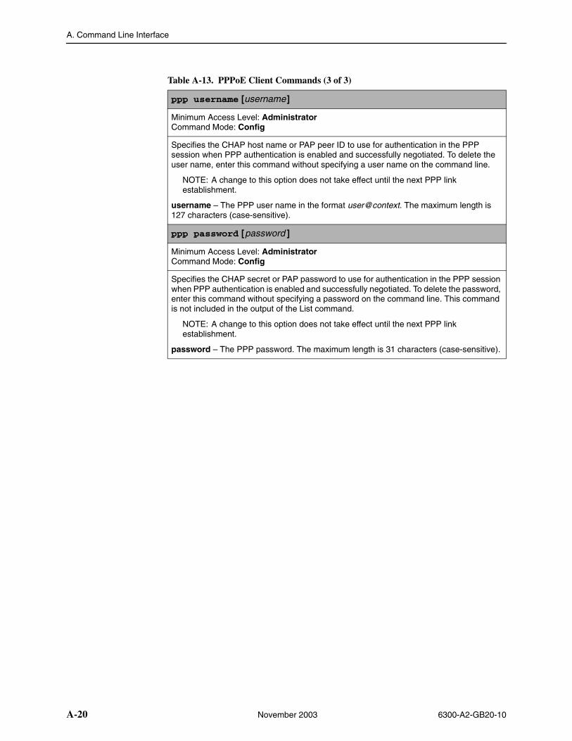
A. Command Line Interface
A-20 November 2003 6300-A2-GB20-10
ppp username [username]
Minimum Access Level: AdministratorCommand Mode: Config
Specifies the CHAP host name or PAP peer ID to use for authentication in the PPP session when PPP authentication is enabled and successfully negotiated. To delete the user name, enter this command without specifying a user name on the command line.
NOTE: A change to this option does not take effect until the next PPP link establishment.
username – The PPP user name in the format user@context. The maximum length is 127 characters (case-sensitive).
ppp password [password ]
Minimum Access Level: AdministratorCommand Mode: Config
Specifies the CHAP secret or PAP password to use for authentication in the PPP session when PPP authentication is enabled and successfully negotiated. To delete the password, enter this command without specifying a password on the command line. This command is not included in the output of the List command.
NOTE: A change to this option does not take effect until the next PPP link establishment.
password – The PPP password. The maximum length is 31 characters (case-sensitive).
Table A-13. PPPoE Client Commands (3 of 3)
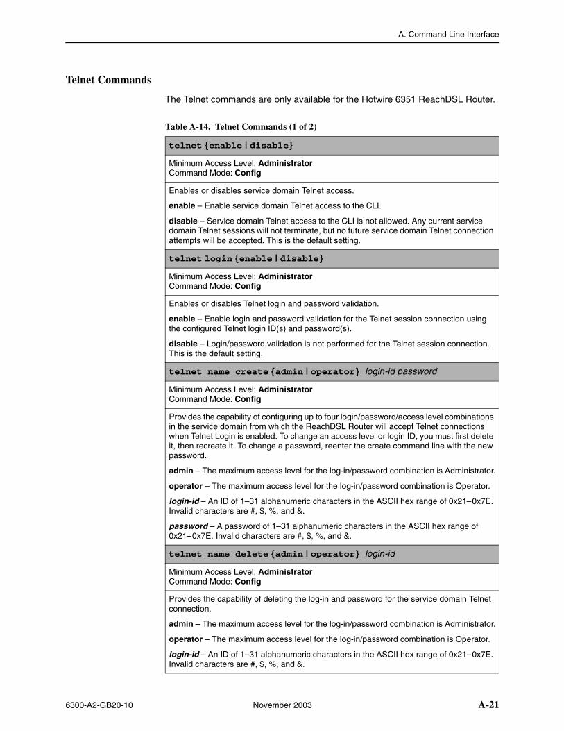
A. Command Line Interface
6300-A2-GB20-10 November 2003 A-21
Telnet Commands
The Telnet commands are only available for the Hotwire 6351 ReachDSL Router.
Table A-14. Telnet Commands (1 of 2)
telnet {enable | disable}
Minimum Access Level: AdministratorCommand Mode: Config
Enables or disables service domain Telnet access.
enable – Enable service domain Telnet access to the CLI.
disable – Service domain Telnet access to the CLI is not allowed. Any current service domain Telnet sessions will not terminate, but no future service domain Telnet connection attempts will be accepted. This is the default setting.
telnet login {enable | disable}
Minimum Access Level: AdministratorCommand Mode: Config
Enables or disables Telnet login and password validation.
enable – Enable login and password validation for the Telnet session connection using the configured Telnet login ID(s) and password(s).
disable – Login/password validation is not performed for the Telnet session connection. This is the default setting.
telnet name create {admin | operator} login-id password
Minimum Access Level: AdministratorCommand Mode: Config
Provides the capability of configuring up to four login/password/access level combinations in the service domain from which the ReachDSL Router will accept Telnet connections when Telnet Login is enabled. To change an access level or login ID, you must first delete it, then recreate it. To change a password, reenter the create command line with the new password.
admin – The maximum access level for the log-in/password combination is Administrator.
operator – The maximum access level for the log-in/password combination is Operator.
login-id – An ID of 1–31 alphanumeric characters in the ASCII hex range of 0x21–0x7E. Invalid characters are #, $, %, and &.
password – A password of 1–31 alphanumeric characters in the ASCII hex range of 0x21–0x7E. Invalid characters are #, $, %, and &.
telnet name delete {admin | operator} login-id
Minimum Access Level: AdministratorCommand Mode: Config
Provides the capability of deleting the log-in and password for the service domain Telnet connection.
admin – The maximum access level for the log-in/password combination is Administrator.
operator – The maximum access level for the log-in/password combination is Operator.
login-id – An ID of 1–31 alphanumeric characters in the ASCII hex range of 0x21–0x7E. Invalid characters are #, $, %, and &.
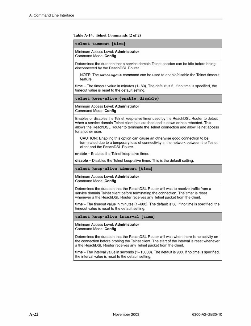
A. Command Line Interface
A-22 November 2003 6300-A2-GB20-10
telnet timeout [time]
Minimum Access Level: AdministratorCommand Mode: Config
Determines the duration that a service domain Telnet session can be idle before being disconnected by the ReachDSL Router.
NOTE: The autologout command can be used to enable/disable the Telnet timeout feature.
time – The timeout value in minutes (1–60). The default is 5. If no time is specified, the timeout value is reset to the default setting.
telnet keep-alive {enable | disable}
Minimum Access Level: AdministratorCommand Mode: Config
Enables or disables the Telnet keep-alive timer used by the ReachDSL Router to detect when a service domain Telnet client has crashed and is down or has rebooted. This allows the ReachDSL Router to terminate the Telnet connection and allow Telnet access for another user.
CAUTION: Enabling this option can cause an otherwise good connection to be terminated due to a temporary loss of connectivity in the network between the Telnet client and the ReachDSL Router.
enable – Enables the Telnet keep-alive timer.
disable – Disables the Telnet keep-alive timer. This is the default setting.
telnet keep-alive timeout [time]
Minimum Access Level: AdministratorCommand Mode: Config
Determines the duration that the ReachDSL Router will wait to receive traffic from a service domain Telnet client before terminating the connection. The timer is reset whenever a the ReachDSL Router receives any Telnet packet from the client.
time – The timeout value in minutes (1–600). The default is 30. If no time is specified, the timeout value is reset to the default setting.
telnet keep-alive interval [time]
Minimum Access Level: AdministratorCommand Mode: Config
Determines the duration that the ReachDSL Router will wait when there is no activity on the connection before probing the Telnet client. The start of the interval is reset whenever a the ReachDSL Router receives any Telnet packet from the client.
time – The interval value in seconds (1–10000). The default is 900. If no time is specified, the interval value is reset to the default setting.
Table A-14. Telnet Commands (2 of 2)
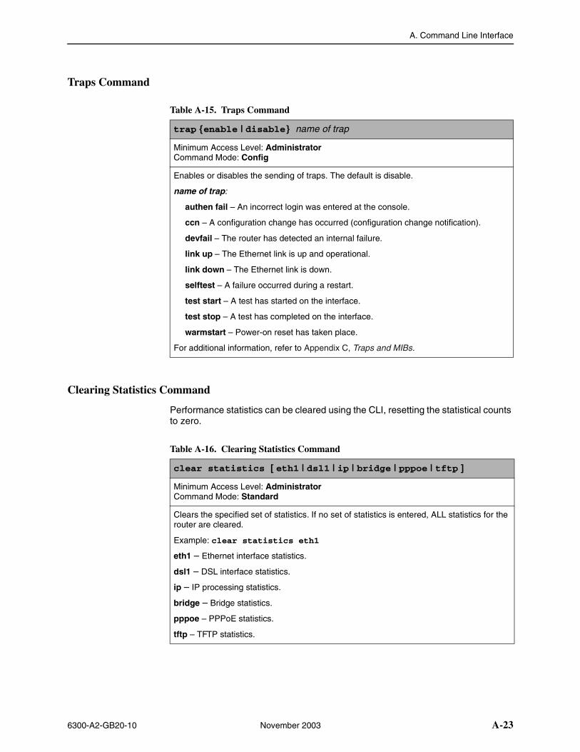
A. Command Line Interface
6300-A2-GB20-10 November 2003 A-23
Traps Command
Clearing Statistics Command
Performance statistics can be cleared using the CLI, resetting the statistical counts to zero.
Table A-15. Traps Command
trap {enable | disable} name of trap
Minimum Access Level: AdministratorCommand Mode: Config
Enables or disables the sending of traps. The default is disable.
name of trap:
authen fail – An incorrect login was entered at the console.
ccn – A configuration change has occurred (configuration change notification).
devfail – The router has detected an internal failure.
link up – The Ethernet link is up and operational.
link down – The Ethernet link is down.
selftest – A failure occurred during a restart.
test start – A test has started on the interface.
test stop – A test has completed on the interface.
warmstart – Power-on reset has taken place.
For additional information, refer to Appendix C, Traps and MIBs.
Table A-16. Clearing Statistics Command
clear statistics [ eth1 | dsl1 | ip | bridge | pppoe | tftp ]
Minimum Access Level: AdministratorCommand Mode: Standard
Clears the specified set of statistics. If no set of statistics is entered, ALL statistics for the router are cleared.
Example: clear statistics eth1
eth1 – Ethernet interface statistics.
dsl1 – DSL interface statistics.
ip – IP processing statistics.
bridge – Bridge statistics.
pppoe – PPPoE statistics.
tftp – TFTP statistics.
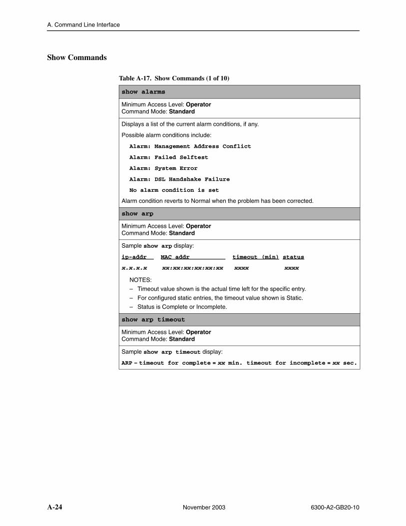
A. Command Line Interface
A-24 November 2003 6300-A2-GB20-10
Show Commands
Table A-17. Show Commands (1 of 10)
show alarms
Minimum Access Level: OperatorCommand Mode: Standard
Displays a list of the current alarm conditions, if any.
Possible alarm conditions include:
Alarm: Management Address Conflict
Alarm: Failed Selftest
Alarm: System Error
Alarm: DSL Handshake Failure
No alarm condition is set
Alarm condition reverts to Normal when the problem has been corrected.
show arp
Minimum Access Level: OperatorCommand Mode: Standard
Sample show arp display:
ip-addr MAC addr timeout (min) status
x.x.x.x xx:xx:xx:xx:xx:xx xxxx xxxx
NOTES:
– Timeout value shown is the actual time left for the specific entry.
– For configured static entries, the timeout value shown is Static.
– Status is Complete or Incomplete.
show arp timeout
Minimum Access Level: OperatorCommand Mode: Standard
Sample show arp timeout display:
ARP – timeout for complete = xx min. timeout for incomplete = xx sec.
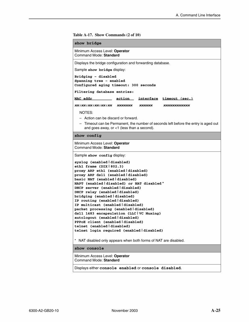
A. Command Line Interface
6300-A2-GB20-10 November 2003 A-25
show bridge
Minimum Access Level: OperatorCommand Mode: Standard
Displays the bridge configuration and forwarding database.
Sample show bridge display:
Bridging – disabledSpanning tree – enabledConfigured aging timeout: 300 seconds
Filtering database entries:
MAC addr action interface timeout (sec.)
xx:xx:xx:xx:xx:xx xxxxxxx xxxxxx xxxxxxxxxxxx
NOTES:
– Action can be discard or forward.
– Timeout can be Permanent, the number of seconds left before the entry is aged out and goes away, or <1 (less than a second).
show config
Minimum Access Level: OperatorCommand Mode: Standard
Sample show config display:
syslog {enabled | disabled}eth1 frame {DIX | 802.3}proxy ARP eth1 {enabled | disabled}proxy ARP dsl1 {enabled | disabled}basic NAT {enabled | disabled}NAPT {enabled | disabled} or NAT disabled *DHCP server {enabled | disabled}DHCP relay {enabled | disabled}bridging {enabled | disabled}IP routing {enabled | disabled}IP multicast {enabled | disabled}packet processing {enabled | disabled}dsl1 1483 encapsulation {LLC | VC Muxing}autologout {enabled | disabled}PPPoE client {enabled | disabled}telnet {enabled | disabled}telnet login required {enabled | disabled}
* NAT disabled only appears when both forms of NAT are disabled.
show console
Minimum Access Level: OperatorCommand Mode: Standard
Displays either console enabled or console disabled.
Table A-17. Show Commands (2 of 10)
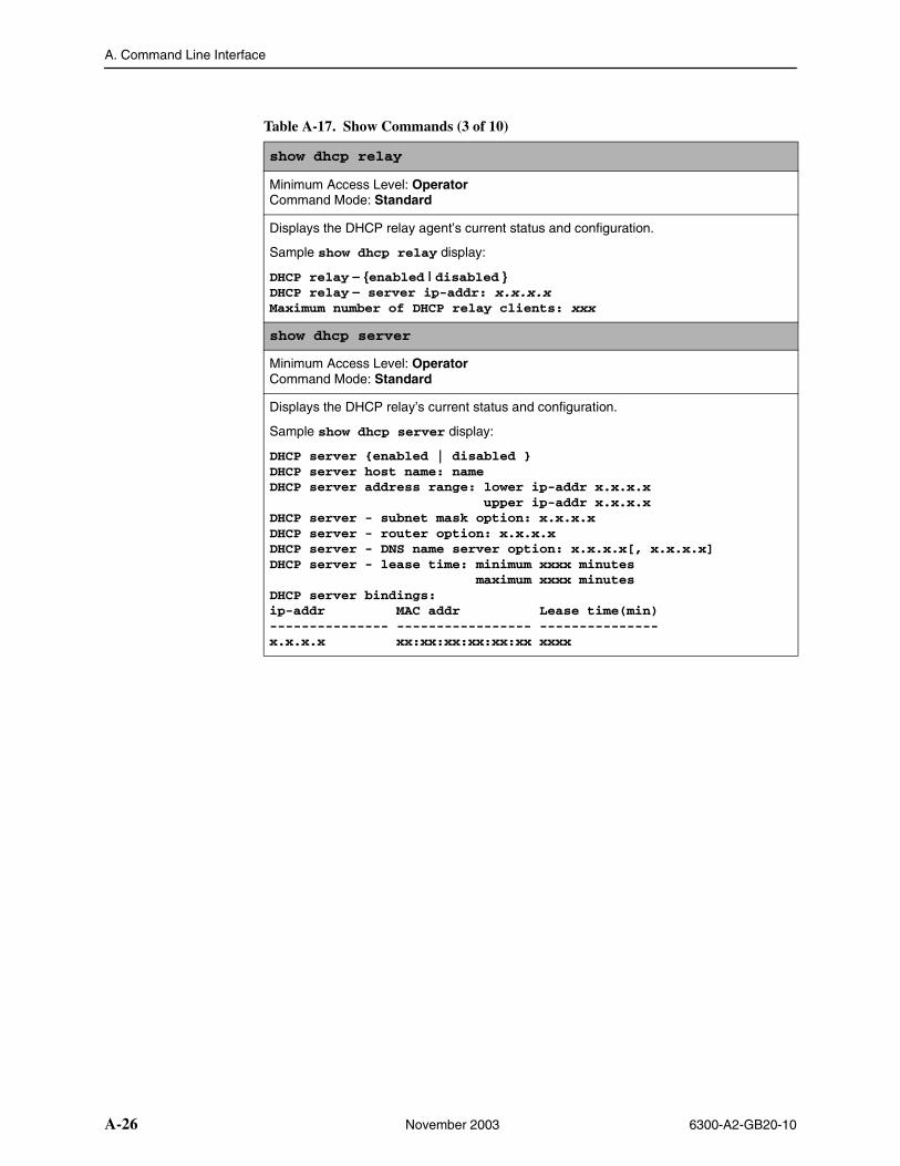
A. Command Line Interface
A-26 November 2003 6300-A2-GB20-10
show dhcp relay
Minimum Access Level: OperatorCommand Mode: Standard
Displays the DHCP relay agent’s current status and configuration.
Sample show dhcp relay display:
DHCP relay – {enabled | disabled }DHCP relay – server ip-addr: x.x.x.xMaximum number of DHCP relay clients: xxx
show dhcp server
Minimum Access Level: OperatorCommand Mode: Standard
Displays the DHCP relay’s current status and configuration.
Sample show dhcp server display:
DHCP server {enabled | disabled }DHCP server host name: nameDHCP server address range: lower ip-addr x.x.x.x upper ip-addr x.x.x.xDHCP server - subnet mask option: x.x.x.xDHCP server - router option: x.x.x.xDHCP server - DNS name server option: x.x.x.x[, x.x.x.x]DHCP server - lease time: minimum xxxx minutes maximum xxxx minutesDHCP server bindings:ip-addr MAC addr Lease time(min)--------------- ----------------- ---------------x.x.x.x xx:xx:xx:xx:xx:xx xxxx
Table A-17. Show Commands (3 of 10)
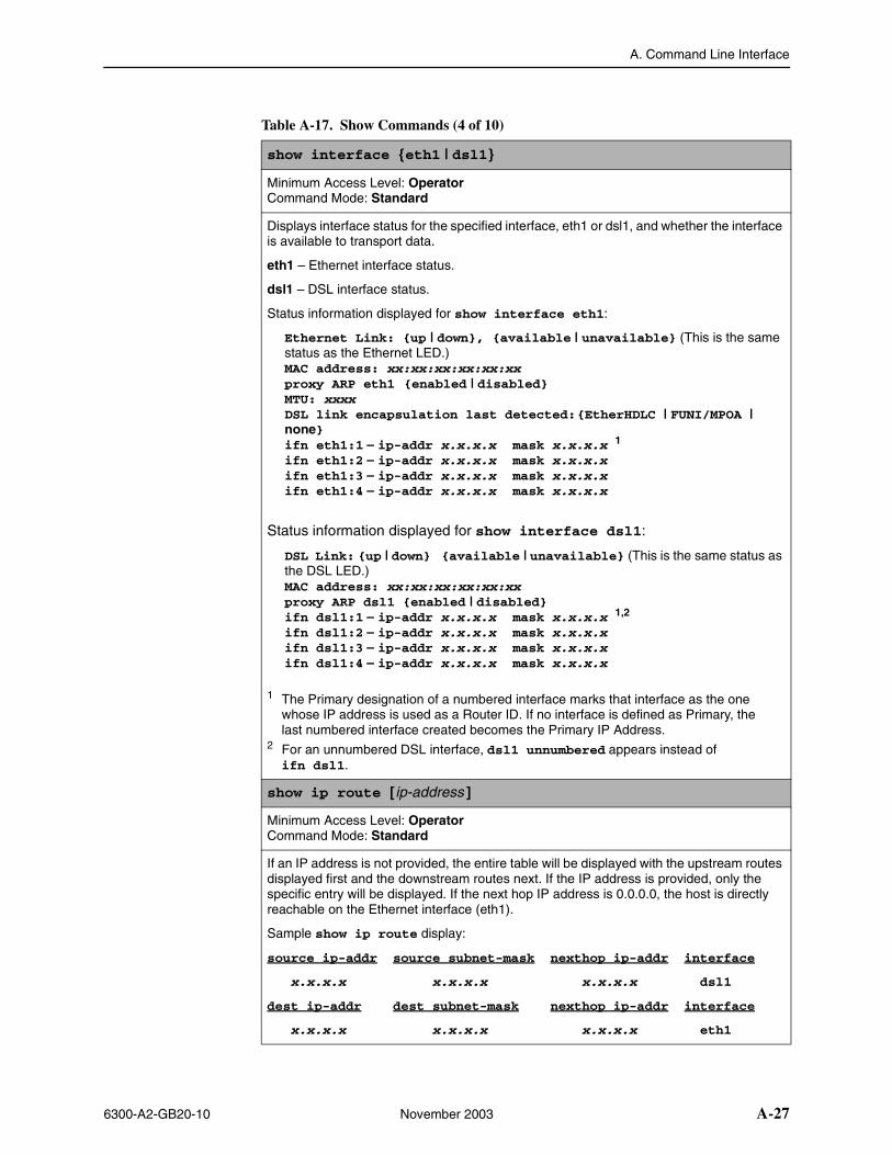
A. Command Line Interface
6300-A2-GB20-10 November 2003 A-27
show interface {eth1 | dsl1}
Minimum Access Level: OperatorCommand Mode: Standard
Displays interface status for the specified interface, eth1 or dsl1, and whether the interface is available to transport data.
eth1 – Ethernet interface status.
dsl1 – DSL interface status.
Status information displayed for show interface eth1:
Ethernet Link: {up | down}, {available | unavailable} (This is the same status as the Ethernet LED.)MAC address: xx:xx:xx:xx:xx:xxproxy ARP eth1 {enabled | disabled}MTU: xxxxDSL link encapsulation last detected:{EtherHDLC | FUNI/MPOA | none}ifn eth1:1 – ip-addr x.x.x.x mask x.x.x.x 1
ifn eth1:2 – ip-addr x.x.x.x mask x.x.x.x ifn eth1:3 – ip-addr x.x.x.x mask x.x.x.x ifn eth1:4 – ip-addr x.x.x.x mask x.x.x.x
Status information displayed for show interface dsl1:
DSL Link: {up | down} {available | unavailable} (This is the same status as the DSL LED.)MAC address: xx:xx:xx:xx:xx:xxproxy ARP dsl1 {enabled | disabled}ifn dsl1:1 – ip-addr x.x.x.x mask x.x.x.x 1,2
ifn dsl1:2 – ip-addr x.x.x.x mask x.x.x.x ifn dsl1:3 – ip-addr x.x.x.x mask x.x.x.x ifn dsl1:4 – ip-addr x.x.x.x mask x.x.x.x
1 The Primary designation of a numbered interface marks that interface as the one whose IP address is used as a Router ID. If no interface is defined as Primary, the last numbered interface created becomes the Primary IP Address.
2 For an unnumbered DSL interface, dsl1 unnumbered appears instead of ifn dsl1.
show ip route [ ip-address ]
Minimum Access Level: OperatorCommand Mode: Standard
If an IP address is not provided, the entire table will be displayed with the upstream routes displayed first and the downstream routes next. If the IP address is provided, only the specific entry will be displayed. If the next hop IP address is 0.0.0.0, the host is directly reachable on the Ethernet interface (eth1).
Sample show ip route display:
source ip-addr source subnet-mask nexthop ip-addr interface
x.x.x.x x.x.x.x x.x.x.x dsl1
dest ip-addr dest subnet-mask nexthop ip-addr interface
x.x.x.x x.x.x.x x.x.x.x eth1
Table A-17. Show Commands (4 of 10)
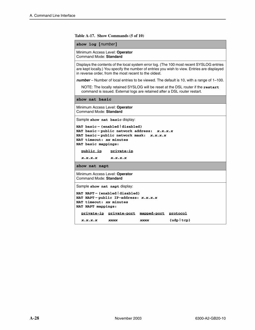
A. Command Line Interface
A-28 November 2003 6300-A2-GB20-10
show log [number ]
Minimum Access Level: OperatorCommand Mode: Standard
Displays the contents of the local system error log. (The 100 most recent SYSLOG entries are kept locally.) You specify the number of entries you wish to view. Entries are displayed in reverse order, from the most recent to the oldest.
number – Number of local entries to be viewed. The default is 10, with a range of 1–100.
NOTE: The locally retained SYSLOG will be reset at the DSL router if the restart command is issued. External logs are retained after a DSL router restart.
show nat basic
Minimum Access Level: OperatorCommand Mode: Standard
Sample show nat basic display:
NAT basic – {enabled | disabled}NAT basic – public network address: x.x.x.xNAT basic – public network mask: x.x.x.xNAT timeout: xx minutesNAT basic mappings:
public ip private-ip
x.x.x.x x.x.x.x
show nat napt
Minimum Access Level: OperatorCommand Mode: Standard
Sample show nat napt display:
NAT NAPT – {enabled | disabled}NAT NAPT – public IP-address: x.x.x.xNAT timeout: xx minutesNAT NAPT mappings:
private-ip private-port mapped-port protocol
x.x.x.x xxxx xxxx {udp | tcp}
Table A-17. Show Commands (5 of 10)
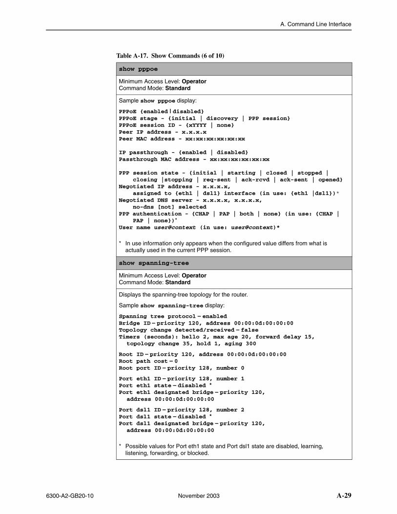
A. Command Line Interface
6300-A2-GB20-10 November 2003 A-29
show pppoe
Minimum Access Level: OperatorCommand Mode: Standard
Sample show pppoe display:
PPPoE {enabled | disabled}PPPoE stage - {initial | discovery | PPP session}PPPoE session ID - {xYYYY | none}Peer IP address - x.x.x.xPeer MAC address - xx:xx:xx:xx:xx:xx
IP passthrough - {enabled | disabled}Passthrough MAC address - xx:xx:xx:xx:xx:xx
PPP session state - {initial | starting | closed | stopped | closing |stopping | req-sent | ack-rcvd | ack-sent | opened}Negotiated IP address - x.x.x.x, assigned to {eth1 | dsl1} interface (in use: {eth1 |dsl1})*Negotiated DNS server - x.x.x.x, x.x.x.x, no-dns [not] selectedPPP authentication - {CHAP | PAP | both | none} (in use: {CHAP | PAP | none})*User name user@context (in use: user@context)*
* In use information only appears when the configured value differs from what is actually used in the current PPP session.
show spanning-tree
Minimum Access Level: OperatorCommand Mode: Standard
Displays the spanning-tree topology for the router.
Sample show spanning-tree display:
Spanning tree protocol – enabledBridge ID – priority 120, address 00:00:0d:00:00:00Topology change detected/received – falseTimers (seconds): hello 2, max age 20, forward delay 15,
topology change 35, hold 1, aging 300
Root ID – priority 120, address 00:00:0d:00:00:00Root path cost – 0Root port ID – priority 128, number 0
Port eth1 ID – priority 128, number 1Port eth1 state – disabled *Port eth1 designated bridge – priority 120,
address 00:00:0d:00:00:00
Port dsl1 ID – priority 128, number 2Port dsl1 state – disabled *Port dsl1 designated bridge – priority 120,
address 00:00:0d:00:00:00
* Possible values for Port eth1 state and Port dsl1 state are disabled, learning, listening, forwarding, or blocked.
Table A-17. Show Commands (6 of 10)
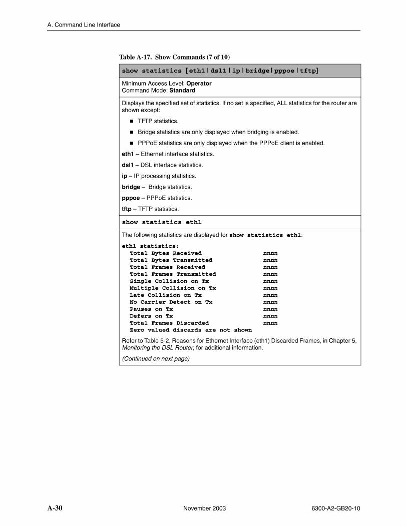
A. Command Line Interface
A-30 November 2003 6300-A2-GB20-10
show statistics [eth1 | dsl1 | ip | bridge | pppoe | tftp]
Minimum Access Level: OperatorCommand Mode: Standard
Displays the specified set of statistics. If no set is specified, ALL statistics for the router are shown except:
� TFTP statistics.
� Bridge statistics are only displayed when bridging is enabled.
� PPPoE statistics are only displayed when the PPPoE client is enabled.
eth1 – Ethernet interface statistics.
dsl1 – DSL interface statistics.
ip – IP processing statistics.
bridge – Bridge statistics.
pppoe – PPPoE statistics.
tftp – TFTP statistics.
show statistics eth1
The following statistics are displayed for show statistics eth1:
eth1 statistics:Total Bytes Received nnnnTotal Bytes Transmitted nnnnTotal Frames Received nnnnTotal Frames Transmitted nnnnSingle Collision on Tx nnnnMultiple Collision on Tx nnnnLate Collision on Tx nnnnNo Carrier Detect on Tx nnnnPauses on Tx nnnnDefers on Tx nnnnTotal Frames Discarded nnnnZero valued discards are not shown
Refer to Table 5-2, Reasons for Ethernet Interface (eth1) Discarded Frames, in Chapter 5, Monitoring the DSL Router, for additional information.
(Continued on next page)
Table A-17. Show Commands (7 of 10)
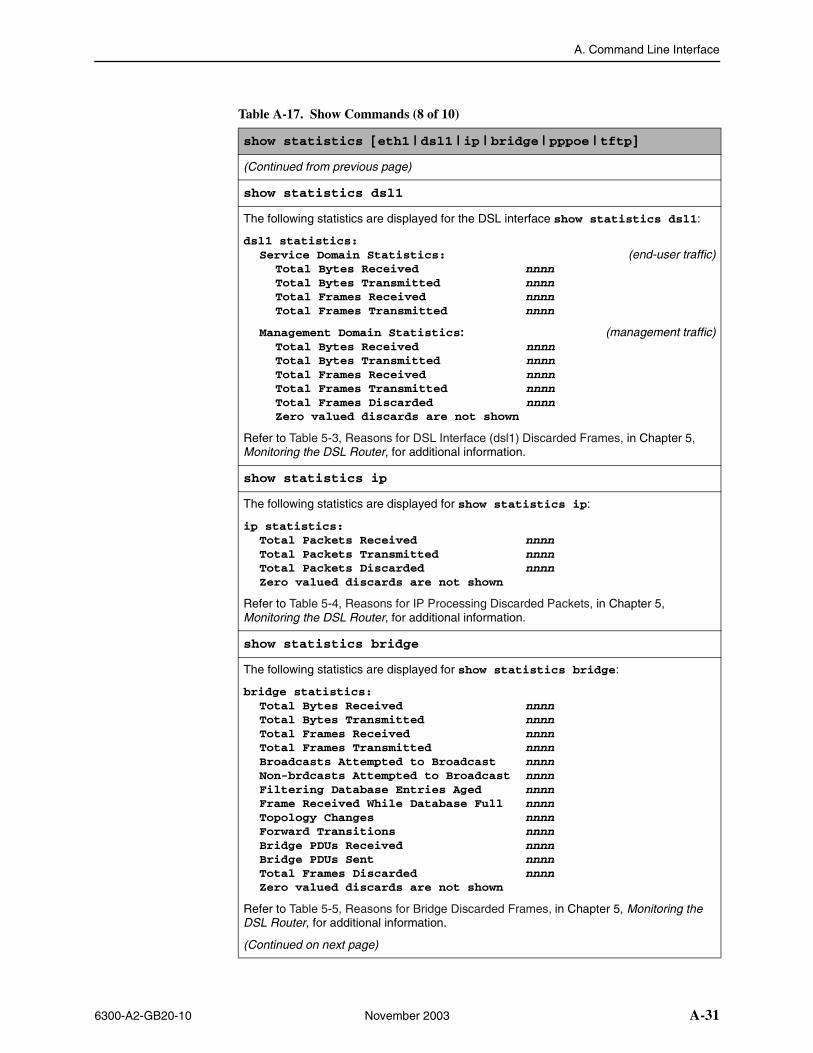
A. Command Line Interface
6300-A2-GB20-10 November 2003 A-31
show statistics [eth1 | dsl1 | ip | bridge | pppoe | tftp]
(Continued from previous page)
show statistics dsl1
The following statistics are displayed for the DSL interface show statistics dsl1:
dsl1 statistics:Service Domain Statistics: (end-user traffic)
Total Bytes Received nnnnTotal Bytes Transmitted nnnnTotal Frames Received nnnnTotal Frames Transmitted nnnn
Management Domain Statistics: (management traffic)Total Bytes Received nnnnTotal Bytes Transmitted nnnnTotal Frames Received nnnnTotal Frames Transmitted nnnnTotal Frames Discarded nnnnZero valued discards are not shown
Refer to Table 5-3, Reasons for DSL Interface (dsl1) Discarded Frames, in Chapter 5, Monitoring the DSL Router, for additional information.
show statistics ip
The following statistics are displayed for show statistics ip:
ip statistics:Total Packets Received nnnnTotal Packets Transmitted nnnnTotal Packets Discarded nnnnZero valued discards are not shown
Refer to Table 5-4, Reasons for IP Processing Discarded Packets, in Chapter 5, Monitoring the DSL Router, for additional information.
show statistics bridge
The following statistics are displayed for show statistics bridge:
bridge statistics:Total Bytes Received nnnnTotal Bytes Transmitted nnnnTotal Frames Received nnnnTotal Frames Transmitted nnnnBroadcasts Attempted to Broadcast nnnnNon-brdcasts Attempted to Broadcast nnnnFiltering Database Entries Aged nnnnFrame Received While Database Full nnnnTopology Changes nnnnForward Transitions nnnnBridge PDUs Received nnnnBridge PDUs Sent nnnnTotal Frames Discarded nnnnZero valued discards are not shown
Refer to Table 5-5, Reasons for Bridge Discarded Frames, in Chapter 5, Monitoring the DSL Router, for additional information.
(Continued on next page)
Table A-17. Show Commands (8 of 10)
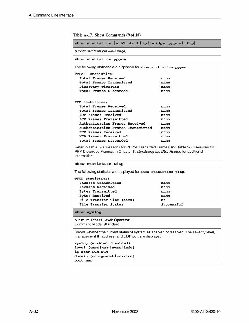
A. Command Line Interface
A-32 November 2003 6300-A2-GB20-10
show statistics [eth1 | dsl1 | ip | bridge | pppoe | tftp]
(Continued from previous page)
show statistics pppoe
The following statistics are displayed for show statistics pppoe:
PPPoE statistics:Total Frames Received nnnnTotal Frames Transmitted nnnnDiscovery Timeouts nnnnTotal Frames Discarded nnnn
PPP statistics:Total Frames Received nnnnTotal Frames Transmitted nnnnLCP Frames Received nnnnLCP Frames Transmitted nnnnAuthentication Frames Received nnnnAuthentication Frames Transmitted nnnnNCP Frames Received nnnnNCP Frames Transmitted nnnnTotal Frames Discarded nnnn
Refer to Table 5-6, Reasons for PPPoE Discarded Frames and Table 5-7, Reasons for PPP Discarded Frames, in Chapter 5, Monitoring the DSL Router, for additional information.
show statistics tftp
The following statistics are displayed for show statistics tftp:
TFTP statistics:Packets Transmitted nnnnPackets Received nnnnBytes Transmitted nnnnBytes Received nnnnFile Transfer Time (secs) nnFile Transfer Status Successful
show syslog
Minimum Access Level: OperatorCommand Mode: Standard
Shows whether the current status of system as enabled or disabled. The severity level, management IP address, and UDP port are displayed.
syslog {enabled | disabled}level {emer | err | norm | info}ip-addr x.x.x.xdomain {management | service}port nnn
Table A-17. Show Commands (9 of 10)
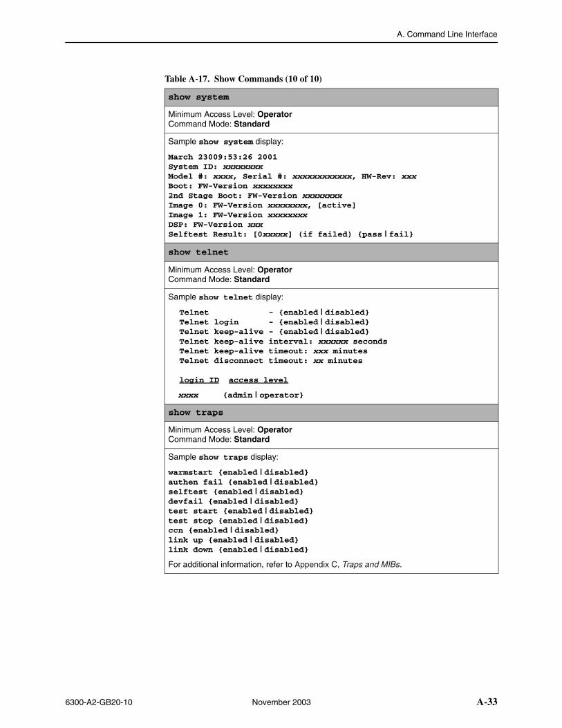
A. Command Line Interface
6300-A2-GB20-10 November 2003 A-33
show system
Minimum Access Level: OperatorCommand Mode: Standard
Sample show system display:
March 23009:53:26 2001System ID: xxxxxxxxModel #: xxxx, Serial #: xxxxxxxxxxxx, HW-Rev: xxxBoot: FW-Version xxxxxxxx2nd Stage Boot: FW-Version xxxxxxxxImage 0: FW-Version xxxxxxxx, [active]Image 1: FW-Version xxxxxxxxDSP: FW-Version xxxSelftest Result: [0xxxxx] (if failed) {pass | fail}
show telnet
Minimum Access Level: OperatorCommand Mode: Standard
Sample show telnet display:
Telnet - {enabled | disabled}Telnet login - {enabled | disabled}Telnet keep-alive - {enabled | disabled}Telnet keep-alive interval: xxxxxx secondsTelnet keep-alive timeout: xxx minutesTelnet disconnect timeout: xx minutes
login ID access level
xxxx {admin | operator}
show traps
Minimum Access Level: OperatorCommand Mode: Standard
Sample show traps display:
warmstart {enabled | disabled}authen fail {enabled | disabled}selftest {enabled | disabled}devfail {enabled | disabled}test start {enabled | disabled}test stop {enabled | disabled}ccn {enabled | disabled}link up {enabled | disabled}link down {enabled | disabled}
For additional information, refer to Appendix C, Traps and MIBs.
Table A-17. Show Commands (10 of 10)

A. Command Line Interface
A-34 November 2003 6300-A2-GB20-10
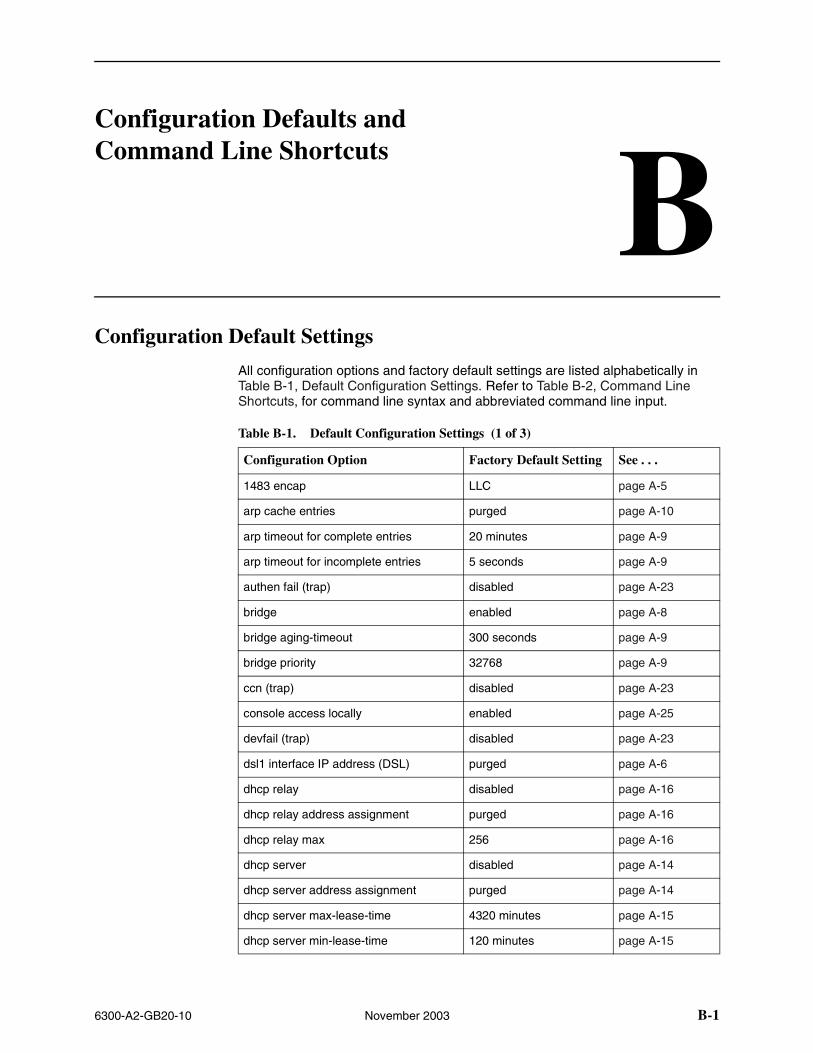
6300-A2-GB20-10 November 2003 B-1
BConfiguration Defaults and Command Line Shortcuts
Configuration Default Settings
All configuration options and factory default settings are listed alphabetically in Table B-1, Default Configuration Settings. Refer to Table B-2, Command Line Shortcuts, for command line syntax and abbreviated command line input.
Table B-1. Default Configuration Settings (1 of 3)
Configuration Option Factory Default Setting See . . .
1483 encap LLC page A-5
arp cache entries purged page A-10
arp timeout for complete entries 20 minutes page A-9
arp timeout for incomplete entries 5 seconds page A-9
authen fail (trap) disabled page A-23
bridge enabled page A-8
bridge aging-timeout 300 seconds page A-9
bridge priority 32768 page A-9
ccn (trap) disabled page A-23
console access locally enabled page A-25
devfail (trap) disabled page A-23
dsl1 interface IP address (DSL) purged page A-6
dhcp relay disabled page A-16
dhcp relay address assignment purged page A-16
dhcp relay max 256 page A-16
dhcp server disabled page A-14
dhcp server address assignment purged page A-14
dhcp server max-lease-time 4320 minutes page A-15
dhcp server min-lease-time 120 minutes page A-15
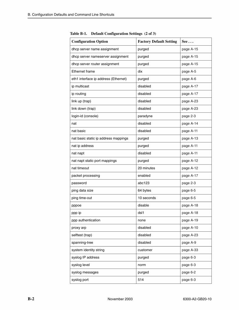
B. Configuration Defaults and Command Line Shortcuts
B-2 November 2003 6300-A2-GB20-10
dhcp server name assignment purged page A-15
dhcp server nameserver assignment purged page A-15
dhcp server router assignment purged page A-15
Ethernet frame dix page A-5
eth1 interface ip address (Ethernet) purged page A-6
ip multicast disabled page A-17
ip routing disabled page A-17
link up (trap) disabled page A-23
link down (trap) disabled page A-23
login-id (console) paradyne page 2-3
nat disabled page A-14
nat basic disabled page A-11
nat basic static ip address mappings purged page A-13
nat ip address purged page A-11
nat napt disabled page A-11
nat napt static port mappings purged page A-12
nat timeout 20 minutes page A-12
packet processing enabled page A-17
password abc123 page 2-3
ping data size 64 bytes page 6-5
ping time-out 10 seconds page 6-5
pppoe disable page A-18
ppp ip dsl1 page A-18
ppp authentication none page A-19
proxy arp disabled page A-10
selftest (trap) disabled page A-23
spanning-tree disabled page A-9
system identity string customer page A-33
syslog IP address purged page 6-3
syslog level norm page 6-3
syslog messages purged page 6-2
syslog port 514 page 6-3
Table B-1. Default Configuration Settings (2 of 3)
Configuration Option Factory Default Setting See . . .
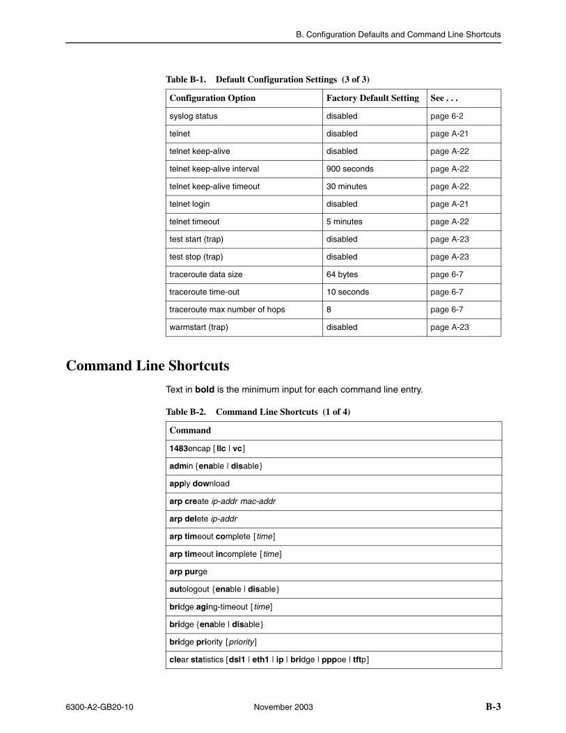
B. Configuration Defaults and Command Line Shortcuts
6300-A2-GB20-10 November 2003 B-3
Command Line Shortcuts
Text in bold is the minimum input for each command line entry.
syslog status disabled page 6-2
telnet disabled page A-21
telnet keep-alive disabled page A-22
telnet keep-alive interval 900 seconds page A-22
telnet keep-alive timeout 30 minutes page A-22
telnet login disabled page A-21
telnet timeout 5 minutes page A-22
test start (trap) disabled page A-23
test stop (trap) disabled page A-23
traceroute data size 64 bytes page 6-7
traceroute time-out 10 seconds page 6-7
traceroute max number of hops 8 page 6-7
warmstart (trap) disabled page A-23
Table B-1. Default Configuration Settings (3 of 3)
Configuration Option Factory Default Setting See . . .
Table B-2. Command Line Shortcuts (1 of 4)
Command
1483encap [ llc | vc ]
admin {enable | disable}
apply download
arp create ip-addr mac-addr
arp delete ip-addr
arp timeout complete [time ]
arp timeout incomplete [time]
arp purge
autologout {enable | disable}
bridge aging-timeout [ time]
bridge {enable | disable}
bridge priority [priority ]
clear statistics [dsl1 | eth1 | ip | bridge | pppoe | tftp]
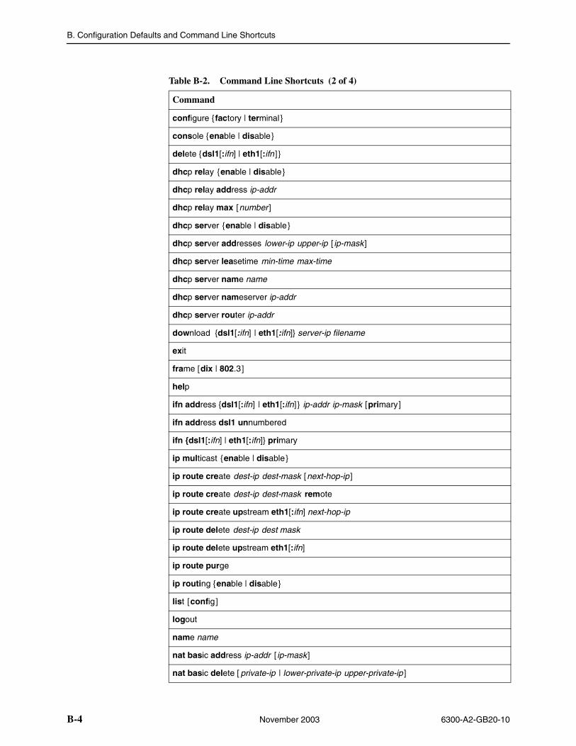
B. Configuration Defaults and Command Line Shortcuts
B-4 November 2003 6300-A2-GB20-10
configure {factory | terminal}
console {enable | disable}
delete {dsl1[:ifn] | eth1[:ifn ]}
dhcp relay {enable | disable}
dhcp relay address ip-addr
dhcp relay max [number]
dhcp server {enable | disable}
dhcp server addresses lower-ip upper-ip [ ip-mask]
dhcp server leasetime min-time max-time
dhcp server name name
dhcp server nameserver ip-addr
dhcp server router ip-addr
download {dsl1[:ifn] | eth1[:ifn]} server-ip filename
exit
frame [dix | 802.3]
help
ifn address {dsl1[:ifn] | eth1[:ifn]} ip-addr ip-mask [primary]
ifn address dsl1 unnumbered
ifn {dsl1[:ifn] | eth1[:ifn]} primary
ip multicast {enable | disable}
ip route create dest-ip dest-mask [next-hop-ip ]
ip route create dest-ip dest-mask remote
ip route create upstream eth1[:ifn] next-hop-ip
ip route delete dest-ip dest mask
ip route delete upstream eth1[:ifn]
ip route purge
ip routing {enable | disable}
list [config]
logout
name name
nat basic address ip-addr [ ip-mask]
nat basic delete [ private-ip | lower-private-ip upper-private-ip ]
Table B-2. Command Line Shortcuts (2 of 4)
Command
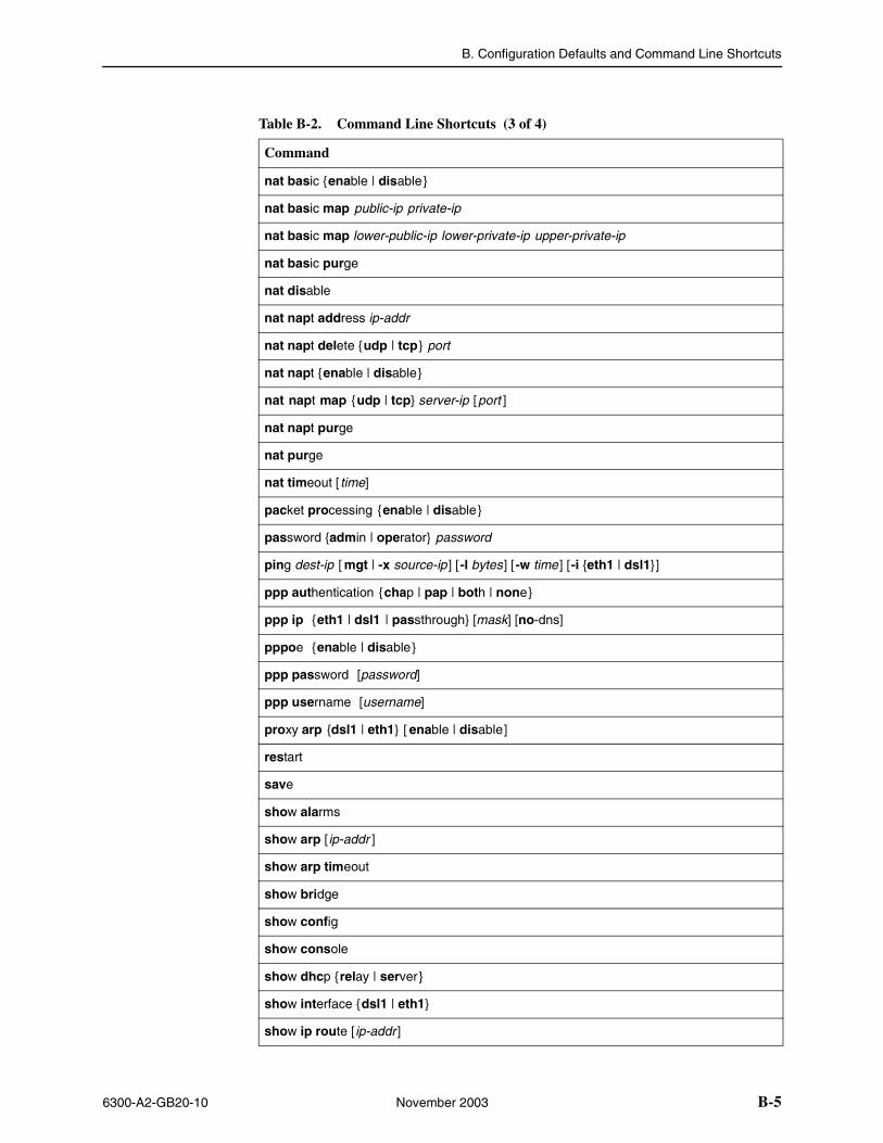
B. Configuration Defaults and Command Line Shortcuts
6300-A2-GB20-10 November 2003 B-5
nat basic {enable | disable}
nat basic map public-ip private-ip
nat basic map lower-public-ip lower-private-ip upper-private-ip
nat basic purge
nat disable
nat napt address ip-addr
nat napt delete {udp | tcp} port
nat napt {enable | disable}
nat napt map {udp | tcp} server-ip [port ]
nat napt purge
nat purge
nat timeout [ time]
packet processing {enable | disable}
password {admin | operator} password
ping dest-ip [ mgt | -x source-ip ] [-l bytes] [-w time ] [-i {eth1 | dsl1}]
ppp authentication {chap | pap | both | none}
ppp ip {eth1 | dsl1 | passthrough} [mask] [no-dns]
pppoe {enable | disable}
ppp password [password]
ppp username [username]
proxy arp {dsl1 | eth1} [ enable | disable]
restart
save
show alarms
show arp [ ip-addr ]
show arp timeout
show bridge
show config
show console
show dhcp {relay | server}
show interface {dsl1 | eth1}
show ip route [ ip-addr ]
Table B-2. Command Line Shortcuts (3 of 4)
Command
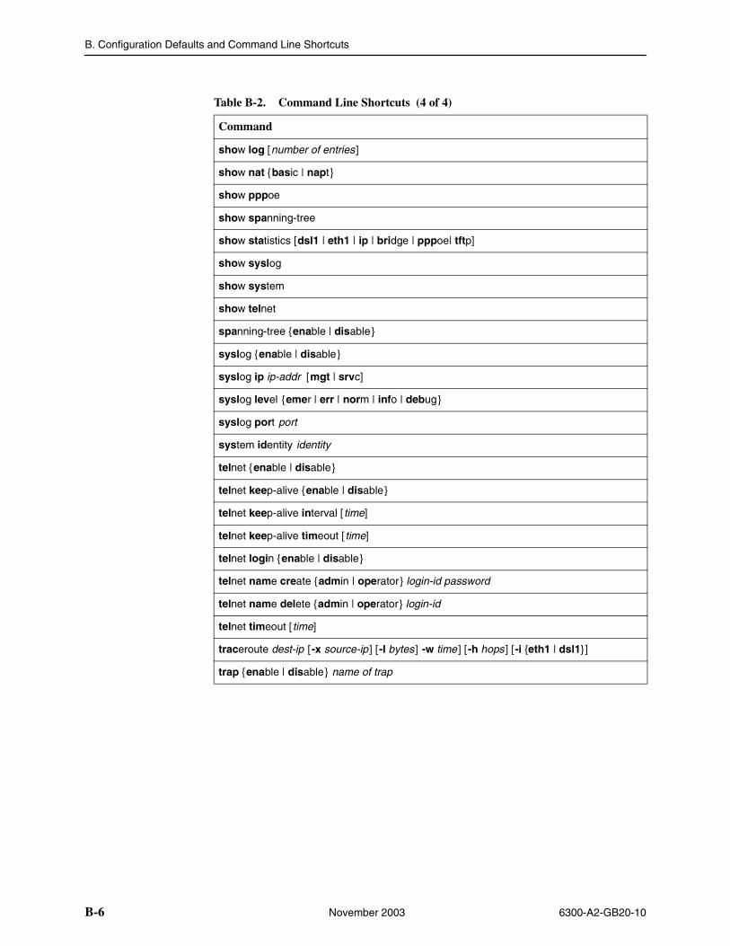
B. Configuration Defaults and Command Line Shortcuts
B-6 November 2003 6300-A2-GB20-10
show log [number of entries]
show nat {basic | napt}
show pppoe
show spanning-tree
show statistics [dsl1 | eth1 | ip | bridge | pppoe| tftp]
show syslog
show system
show telnet
spanning-tree {enable | disable}
syslog {enable | disable}
syslog ip ip-addr [mgt | srvc]
syslog level {emer | err | norm | info | debug}
syslog port port
system identity identity
telnet {enable | disable}
telnet keep-alive {enable | disable}
telnet keep-alive interval [ time]
telnet keep-alive timeout [time]
telnet login {enable | disable}
telnet name create {admin | operator} login-id password
telnet name delete {admin | operator} login-id
telnet timeout [time]
traceroute dest-ip [-x source-ip ] [-l bytes] -w time ] [-h hops ] [-i {eth1 | dsl1}]
trap {enable | disable} name of trap
Table B-2. Command Line Shortcuts (4 of 4)
Command
6300-A2-GB20-10 November 2003 C-1
CTraps and MIBs
SNMP Overview
The Simple Network Management Protocol (SNMP) is an application-level protocol used in network management to gather information from network devices. Each DSL router runs an SNMP agent that collects data. The network management station in the NAP domain can exercise all the management functions remotely from the Network Operations Center (NOC).
There is no discovery of the DSL router, and it does not appear on the Management Domain map. SNMP security is configured on the MCC card and all SNMP requests to the DSL router are authenticated at the MCC. The MCC is the destination for all traps originated by the DSL router.
See the Hotwire Management Communications Controller (MCC) Card, IP Conservative, User’s Guide for more information on SNMP.
NOTE:
There are several SNMP Sets that result in resetting the DSL router. When this happens, the NMS that sent the Set command may not receive a response from the DSL router and will time out. This is not an error.
Traps Overview
Traps inform the NMS of an alert occurring in the system (e.g., threshold exceeded). Traps are sent at the start and completion of a test or alarm condition. The MCC is the destination for all traps originated by the DSL router. These traps are then rebuilt with the trap destination information stored on the MCC and forwarded to the appropriate trap managers.
Traps are configured via a Telnet session, terminal session, or via SNMP, and are based on community names. Traps are included in the MIB II, Entity and Hotwire Enterprise MIB definitions. MIBs can be accessed through the Paradyne Web site at www.paradyne.com. Select Technical Support → MIBS.
The DSL system can send traps to three IP addressable destinations per community (for a total of 12 destinations).
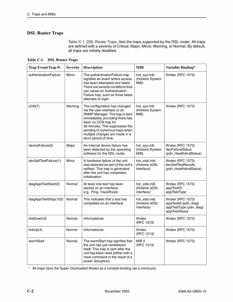
C. Traps and MIBs
C-2 November 2003 6300-A2-GB20-10
DSL Router Traps
Table C-1, DSL Router Traps, lists the traps supported by the DSL router. All traps are defined with a severity of Critical, Major, Minor, Warning, or Normal. By default, all traps are initially disabled.
Table C-1. DSL Router Traps
Trap Event(Trap #) Severity Description MIB Variable Binding*
authenticationFailure Minor The authenticationFailure trap signifies an event where access has been attempted and failed. There are several conditions that can cause an Authentication Failure trap, such as three failed attempts to login.
hot_sys.mib (Hotwire System MIB)
ifIndex (RFC 1573)
cCN(7) Warning The configuration has changed via the user interface or an SNMP Manager. The trap is sent immediately, providing there has been no CCN trap for 30 minutes. This suppresses the sending of numerous traps when multiple changes are made in a short period of time.
hot_sys.mib (Hotwire System MIB)
ifIndex (RFC 1573)
deviceFailure(2) Major An internal device failure has been detected by the operating software for the DSL router.
hot_sys.mib (Hotwire System MIB)
ifIndex (RFC 1573)devFailureStatus (pdn_HealthAndStatus)
devSelfTestFailure(1) Minor A hardware failure of the unit was detected as part of the unit’s selftest. This trap is generated after the unit has completed initialization.
hot_xdsl.mib (Hotwire xDSL interface)
ifIndex (RFC 1573)devSelfTestResults (pdn_HealthAndStatus)
diagApplTestStart(2) Normal At least one test has been started on an interface; e.g., Ping, TraceRoute.
hot_xdsl.mib (Hotwire xDSL interface)
ifIndex (RFC 1573)applTestIDapplTestType
diagApplTestStop(102) Normal This indicates that a test has completed on an interface.
hot_xdsl.mib (Hotwire xDSL interface)
ifIndex (RFC 1573)applTestId (pdn_diag)applTestType (pdn_diag)applTestStatus
linkDown(3) Normal Informational. ifIndex (RFC 1573)
ifIndex (RFC 1573)
linkUp(4) Normal Informational. ifIndex (RFC 1213)
ifIndex (RFC 1573)
warmStart Normal The warmStart trap signifies that the unit has just reinitialized itself. This trap is sent after the unit has been reset (either with a reset command or the result of a power disruption).
MIB II (RFC 1213)
ifIndex (RFC 1573)
* All traps have the Super Overloaded ifIndex as a variable-binding (as a minimum).
C. Traps and MIBs
6300-A2-GB20-10 November 2003 C-3
MIBs Overview
The Hotwire DSL system supports standard as well as Paradyne Enterprise MIBs. Various configuration, status, and statistical data within the SNMP agent is accessible from the NMS. The content of an SNMP agent’s MIBs is defined by various Internet Request for Comments (RFC) documents.
The following sections provide brief descriptions about supported MIBs. Complete, up-to-date details about the content of all DSL MIBs are available on the Paradyne Web site at www.paradyne.com. Select Technical Support → MIBs.
Standard MIBs
Standard MIBs supported consist of the following:
� RFC 1213: MIB II
� RFC 1573: Evolution of the Interfaces Group
� RFC 2096: IP Forwarding Table MIB
� RFC 2665: Ethernet-Like MIB
MIB II (RFC 1213)
The objects defined by MIB II (RFC 1213) are organized into ten groups:
� System Group – Fully supported. Refer to System Group.
� Interfaces Group – Refer to Interfaces Group (RFC 1573) on page C-5 and Extension to Interfaces Table (RFC 1573) on page C-7.
� Address Translation Group – Not supported.
� IP Group – Refer to IP Group (RFC 1213) on page C-8 and IP CIDR Route Group (RFC 2096) on page C-9.
� ICMP Group – Fully supported.
� TCP Group – Fully supported.
� UDP Group – Fully supported.
� EGP Group – Not supported.
� Transmission Group – Refer to Transmission Group on page C-10.
� SNMP Group – Refer to SNMP Group on page C-10.
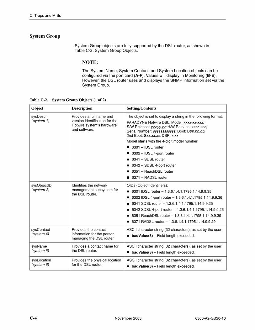
C. Traps and MIBs
C-4 November 2003 6300-A2-GB20-10
System Group
System Group objects are fully supported by the DSL router, as shown in Table C-2, System Group Objects.
NOTE:
The System Name, System Contact, and System Location objects can be configured via the port card (A-F). Values will display in Monitoring (B-E). However, the DSL router uses and displays the SNMP information set via the System Group.
Table C-2. System Group Objects (1 of 2)
Object Description Setting/Contents
sysDescr(system 1)
Provides a full name and version identification for the Hotwire system’s hardware and software.
The object is set to display a string in the following format:
PARADYNE Hotwire DSL; Model: xxxx-xx-xxx; S/W Release: yyy.yy.yy; H/W Release: zzzz-zzz; Serial Number: ssssssssssss; Boot: Bbb.bb.bb; 2nd Boot: Sxx.xx.xx; DSP: x.xx
Model starts with the 4-digit model number:
� 6301 – IDSL router
� 6302 – IDSL 4-port router
� 6341 – SDSL router
� 6342 – SDSL 4-port router
� 6351 – ReachDSL router
� 6371 – RADSL router
sysObjectID(system 2)
Identifies the network management subsystem for the DSL router.
OIDs (Object Identifiers):
� 6301 IDSL router – 1.3.6.1.4.1.1795.1.14.9.9.35
� 6302 IDSL 4-port router – 1.3.6.1.4.1.1795.1.14.9.9.36
� 6341 SDSL router – 1.3.6.1.4.1.1795.1.14.9.9.25
� 6342 SDSL 4-port router – 1.3.6.1.4.1.1795.1.14.9.9.26
� 6351 ReachDSL router – 1.3.6.1.4.1.1795.1.14.9.9.39
� 6371 RADSL router – 1.3.6.1.4.1.1795.1.14.9.9.29
sysContact(system 4)
Provides the contact information for the person managing the DSL router.
ASCII character string (32 characters), as set by the user:
� badValue(3) – Field length exceeded.
sysName(system 5)
Provides a contact name for the DSL router.
ASCII character string (32 characters), as set by the user:
� badValue(3) – Field length exceeded.
sysLocation(system 6)
Provides the physical location for the DSL router.
ASCII character string (32 characters), as set by the user:
� badValue(3) – Field length exceeded.
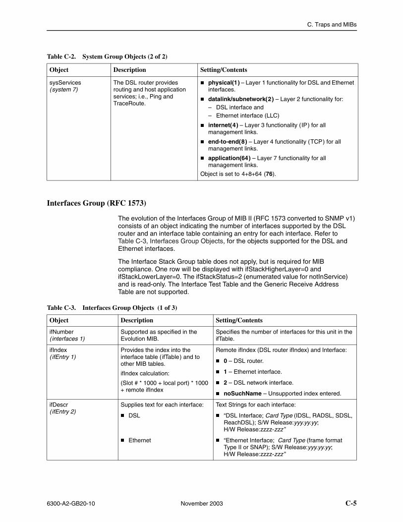
C. Traps and MIBs
6300-A2-GB20-10 November 2003 C-5
Interfaces Group (RFC 1573)
The evolution of the Interfaces Group of MIB II (RFC 1573 converted to SNMP v1) consists of an object indicating the number of interfaces supported by the DSL router and an interface table containing an entry for each interface. Refer to Table C-3, Interfaces Group Objects, for the objects supported for the DSL and Ethernet interfaces.
The Interface Stack Group table does not apply, but is required for MIB compliance. One row will be displayed with ifStackHigherLayer=0 and ifStackLowerLayer=0. The ifStackStatus=2 (enumerated value for notInService) and is read-only. The Interface Test Table and the Generic Receive Address Table are not supported.
Object Description Setting/Contents
sysServices(system 7)
The DSL router provides routing and host application services; i.e., Ping and TraceRoute.
� physical(1) – Layer 1 functionality for DSL and Ethernet interfaces.
� datalink/subnetwork(2) – Layer 2 functionality for:– DSL interface and– Ethernet interface (LLC)
� internet(4) – Layer 3 functionality (IP) for all management links.
� end-to-end(8) – Layer 4 functionality (TCP) for all management links.
� application(64) – Layer 7 functionality for all management links.
Object is set to 4+8+64 (76).
Table C-2. System Group Objects (2 of 2)
Table C-3. Interfaces Group Objects (1 of 3)
Object Description Setting/Contents
ifNumber(interfaces 1)
Supported as specified in the Evolution MIB.
Specifies the number of interfaces for this unit in the ifTable.
ifIndex(ifEntry 1)
Provides the index into the interface table ( ifTable) and to other MIB tables.
ifIndex calculation:
(Slot # * 1000 + local port) * 1000 + remote ifIndex
Remote ifIndex (DSL router ifIndex) and Interface:
� 0 – DSL router.
� 1 – Ethernet interface.
� 2 – DSL network interface.
� noSuchName – Unsupported index entered.
ifDescr(ifEntry 2)
Supplies text for each interface:
� DSL
� Ethernet
Text Strings for each interface:
� “DSL Interface; Card Type (IDSL, RADSL, SDSL, ReachDSL); S/W Release:yyy.yy.yy; H/W Release:zzzz-zzz ”
� “Ethernet Interface; Card Type (frame format Type II or SNAP); S/W Release:yyy.yy.yy; H/W Release:zzzz-zzz ”
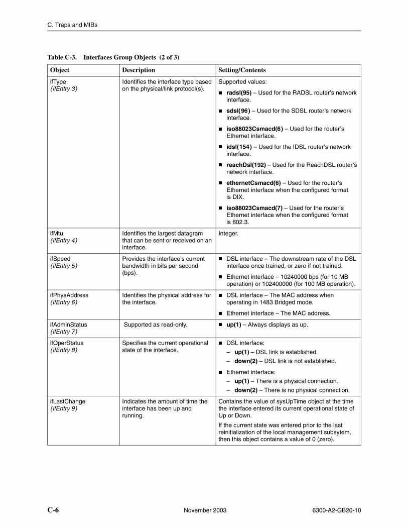
C. Traps and MIBs
C-6 November 2003 6300-A2-GB20-10
Object Description Setting/Contents
ifType(ifEntry 3)
Identifies the interface type based on the physical/link protocol(s).
Supported values:
� radsl(95) – Used for the RADSL router’s network interface.
� sdsl(96) – Used for the SDSL router’s network interface.
� iso88023Csmacd(6) – Used for the router’s Ethernet interface.
� idsl(154) – Used for the IDSL router’s network interface.
� reachDsl(192) – Used for the ReachDSL router’s network interface.
� ethernetCsmacd(6) – Used for the router’s Ethernet interface when the configured format is DIX.
� iso88023Csmacd(7) – Used for the router’s Ethernet interface when the configured format is 802.3.
ifMtu (ifEntry 4)
Identifies the largest datagram that can be sent or received on an interface.
Integer.
ifSpeed(ifEntry 5)
Provides the interface’s current bandwidth in bits per second (bps).
� DSL interface – The downstream rate of the DSL interface once trained, or zero if not trained.
� Ethernet interface – 10240000 bps (for 10 MB operation) or 102400000 (for 100 MB operation).
ifPhysAddress (ifEntry 6)
Identifies the physical address for the interface.
� DSL interface – The MAC address when operating in 1483 Bridged mode.
� Ethernet interface – The MAC address.
ifAdminStatus(ifEntry 7)
Supported as read-only. � up(1) – Always displays as up.
ifOperStatus(ifEntry 8)
Specifies the current operational state of the interface.
� DSL interface:
– up(1) – DSL link is established.
– down(2) – DSL link is not established.
� Ethernet interface:
– up(1) – There is a physical connection.
– down(2) – There is no physical connection.
ifLastChange(ifEntry 9)
Indicates the amount of time the interface has been up and running.
Contains the value of sysUpTime object at the time the interface entered its current operational state of Up or Down.
If the current state was entered prior to the last reinitialization of the local management subsytem, then this object contains a value of 0 (zero).
Table C-3. Interfaces Group Objects (2 of 3)
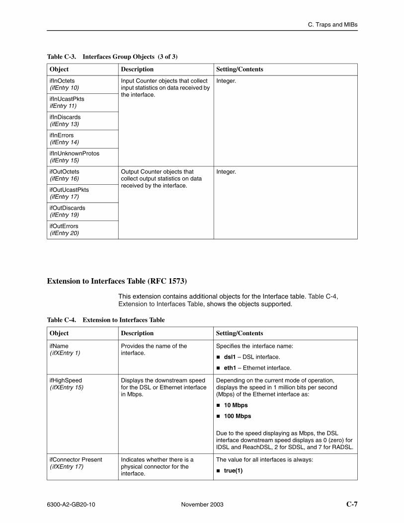
C. Traps and MIBs
6300-A2-GB20-10 November 2003 C-7
Extension to Interfaces Table (RFC 1573)
This extension contains additional objects for the Interface table. Table C-4, Extension to Interfaces Table, shows the objects supported.
Object Description Setting/Contents
ifInOctets (ifEntry 10)
Input Counter objects that collect input statistics on data received by the interface.
Integer.
ifInUcastPkts ifEntry 11)
ifInDiscards (ifEntry 13)
ifInErrors (ifEntry 14)
ifInUnknownProtos (ifEntry 15)
ifOutOctets (ifEntry 16)
Output Counter objects that collect output statistics on data received by the interface.
Integer.
ifOutUcastPkts (ifEntry 17)
ifOutDiscards (ifEntry 19)
ifOutErrors (ifEntry 20)
Table C-3. Interfaces Group Objects (3 of 3)
Table C-4. Extension to Interfaces Table
Object Description Setting/Contents
ifName(ifXEntry 1)
Provides the name of the interface.
Specifies the interface name:
� dsl1 – DSL interface.
� eth1 – Ethernet interface.
ifHighSpeed(ifXEntry 15)
Displays the downstream speed for the DSL or Ethernet interface in Mbps.
Depending on the current mode of operation, displays the speed in 1 million bits per second (Mbps) of the Ethernet interface as:
� 10 Mbps
� 100 Mbps
Due to the speed displaying as Mbps, the DSL interface downstream speed displays as 0 (zero) for IDSL and ReachDSL, 2 for SDSL, and 7 for RADSL.
ifConnector Present(ifXEntry 17)
Indicates whether there is a physical connector for the interface.
The value for all interfaces is always:
� true(1)
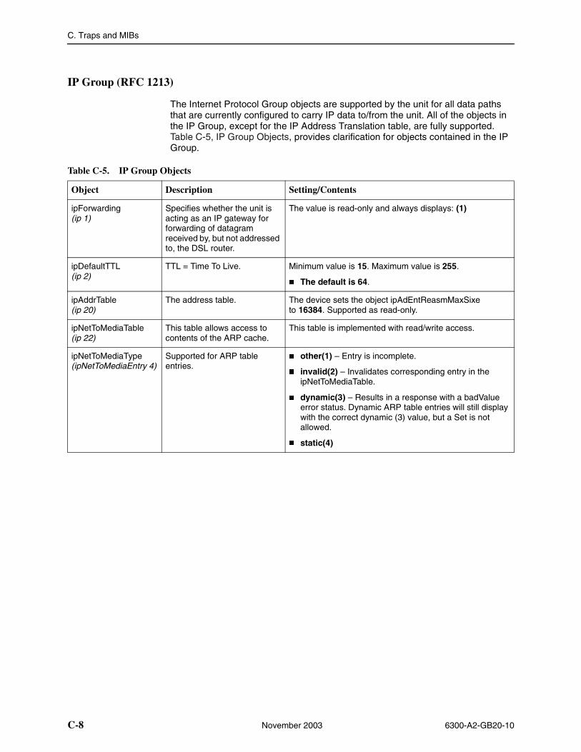
C. Traps and MIBs
C-8 November 2003 6300-A2-GB20-10
IP Group (RFC 1213)
The Internet Protocol Group objects are supported by the unit for all data paths that are currently configured to carry IP data to/from the unit. All of the objects in the IP Group, except for the IP Address Translation table, are fully supported. Table C-5, IP Group Objects, provides clarification for objects contained in the IP Group.
Table C-5. IP Group Objects
Object Description Setting/Contents
ipForwarding(ip 1)
Specifies whether the unit is acting as an IP gateway for forwarding of datagram received by, but not addressed to, the DSL router.
The value is read-only and always displays: (1)
ipDefaultTTL(ip 2)
TTL = Time To Live. Minimum value is 15. Maximum value is 255.
� The default is 64.
ipAddrTable (ip 20)
The address table. The device sets the object ipAdEntReasmMaxSixe to 16384. Supported as read-only.
ipNetToMediaTable (ip 22)
This table allows access to contents of the ARP cache.
This table is implemented with read/write access.
ipNetToMediaType (ipNetToMediaEntry 4)
Supported for ARP table entries.
� other(1) – Entry is incomplete.
� invalid(2) – Invalidates corresponding entry in the ipNetToMediaTable.
� dynamic(3) – Results in a response with a badValue error status. Dynamic ARP table entries will still display with the correct dynamic (3) value, but a Set is not allowed.
� static(4)
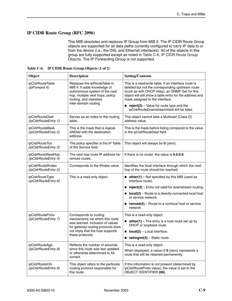
C. Traps and MIBs
6300-A2-GB20-10 November 2003 C-9
IP CIDR Route Group (RFC 2096)
This MIB obsoletes and replaces IP Group from MIB II. The IP CIDR Route Group objects are supported for all data paths currently configured to carry IP data to or from the device (i.e., the DSL and Ethernet interfaces). All of the objects in this group are fully supported except as noted in Table C-6, IP CIDR Route Group Objects. The IP Forwarding Group is not supported.
Table C-6. IP CIDR Route Group Objects (1 of 2)
Object Description Setting/Contents
ipCidrRouteTable (ipForward 4)
Replaces the ipRouteTable in MIB II. It adds knowledge of autonomous system of the next hop, multiple next hops, policy routing, and classless inter-domain routing.
This is a read/write table. If an interface route is deleted but not the corresponding upstream route (such as with DHCP relay), an SNMP Get for this object will still show a table entry for the address and mask assigned to the interface.
� reject(2) – Value for route type and the ipCidrRouteDownstreamValid will be false.
ipCidrRouteDest (ipCidrRouteEntry 1)
Serves as an index to the routing table.
This object cannot take a Multicast (Class D) address value.
ipCidrRouteMask (ipCidrRouteEntry 2)
This is the mask that is logical- ANDed with the destination address.
This is the mask before being compared to the value in the ipCidrRouteDest field.
ipCidrRouteTos (ipCidrRouteEntry 3)
The policy specifier is the IP Table of the Service field.
This object will always be 0 (zero).
ipCidrRouteNextHop (ipCidrRouteEntry 4)
The next hop route IP address for remote routes.
If there is no router, the value is 0.0.0.0.
ipCidrRouteIfIndex (ipCidrRouteEntry 5)
Corresponds to the IfIndex value. Identifies the local interface through which the next hop of the route should be reached.
ipCidrRouteType (ipCidrRouteEntry 6)
This is a read-only object. � other(1) – Not specified by this MIB (used as interface route).
� reject(2) – Entry not valid for downstream routing.
� local(3) – Route to a directly connected local host or service network.
� remote(4) – Route to a nonlocal host or service network.
ipCidrRouteProto (ipCidrRouteEntry 7)
Corresponds to routing mechanisms via which this route was learned. Inclusion of values for gateway routing protocols does not imply that the host supports these protocols.
This is a read-only object.
� other(1) – The entry is a host route set up by DHCP or loopback route.
� local(2) – Local interface.
� netmgmt(3) – Static route.
ipCidrRouteAge (ipCidrRouteEntry 8)
Reflects the number of seconds since this route was last updated or otherwise determined to be correct.
This is a read-only object.
When displayed, a value of 0 (zero) represents a route that will be retained permanently.
ipCidrRouteInfo (ipCidrRouteEntry 9)
This object refers to the particular routing protocol responsible for this route.
If this information is not present (determined by ipCidrRouteProto value), the value is set to the OBJECT IDENTIFIER (00).
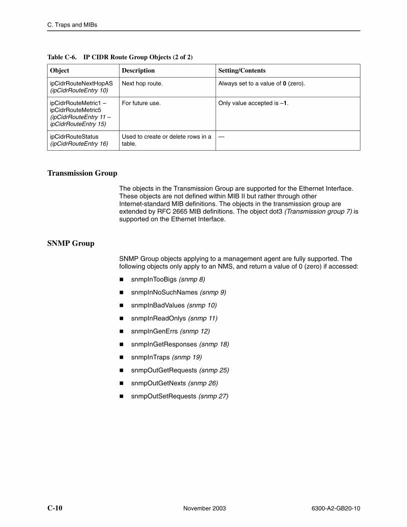
C. Traps and MIBs
C-10 November 2003 6300-A2-GB20-10
Transmission Group
The objects in the Transmission Group are supported for the Ethernet Interface. These objects are not defined within MIB II but rather through other Internet-standard MIB definitions. The objects in the transmission group are extended by RFC 2665 MIB definitions. The object dot3 (Transmission group 7) is supported on the Ethernet Interface.
SNMP Group
SNMP Group objects applying to a management agent are fully supported. The following objects only apply to an NMS, and return a value of 0 (zero) if accessed:
� snmpInTooBigs (snmp 8)
� snmpInNoSuchNames (snmp 9)
� snmpInBadValues (snmp 10)
� snmpInReadOnlys (snmp 11)
� snmpInGenErrs (snmp 12)
� snmpInGetResponses (snmp 18)
� snmpInTraps (snmp 19)
� snmpOutGetRequests (snmp 25)
� snmpOutGetNexts (snmp 26)
� snmpOutSetRequests (snmp 27)
ipCidrRouteNextHopAS (ipCidrRouteEntry 10)
Next hop route. Always set to a value of 0 (zero).
ipCidrRouteMetric1 – ipCidrRouteMetric5 (ipCidrRouteEntry 11 – ipCidrRouteEntry 15)
For future use. Only value accepted is –1.
ipCidrRouteStatus (ipCidrRouteEntry 16)
Used to create or delete rows in a table.
—
Table C-6. IP CIDR Route Group Objects (2 of 2)
Object Description Setting/Contents
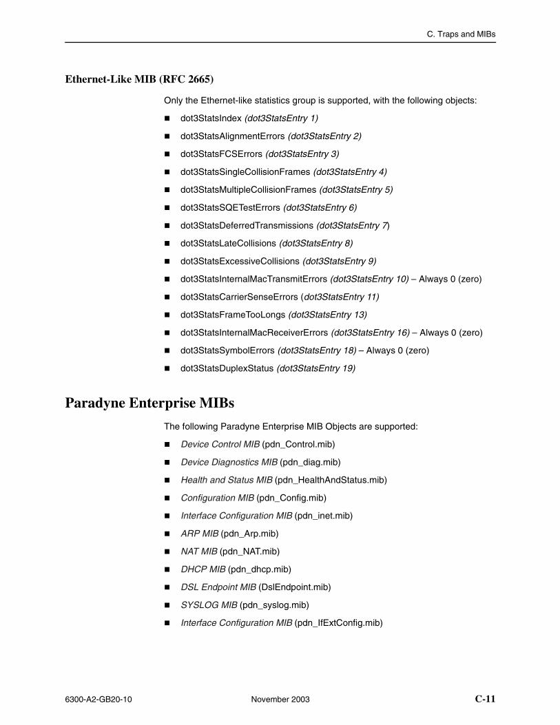
C. Traps and MIBs
6300-A2-GB20-10 November 2003 C-11
Ethernet-Like MIB (RFC 2665)
Only the Ethernet-like statistics group is supported, with the following objects:
� dot3StatsIndex (dot3StatsEntry 1)
� dot3StatsAlignmentErrors (dot3StatsEntry 2)
� dot3StatsFCSErrors (dot3StatsEntry 3)
� dot3StatsSingleCollisionFrames (dot3StatsEntry 4)
� dot3StatsMultipleCollisionFrames (dot3StatsEntry 5)
� dot3StatsSQETestErrors (dot3StatsEntry 6)
� dot3StatsDeferredTransmissions (dot3StatsEntry 7)
� dot3StatsLateCollisions (dot3StatsEntry 8)
� dot3StatsExcessiveCollisions (dot3StatsEntry 9)
� dot3StatsInternalMacTransmitErrors (dot3StatsEntry 10) – Always 0 (zero)
� dot3StatsCarrierSenseErrors (dot3StatsEntry 11)
� dot3StatsFrameTooLongs (dot3StatsEntry 13)
� dot3StatsInternalMacReceiverErrors (dot3StatsEntry 16) – Always 0 (zero)
� dot3StatsSymbolErrors (dot3StatsEntry 18) – Always 0 (zero)
� dot3StatsDuplexStatus (dot3StatsEntry 19)
Paradyne Enterprise MIBs
The following Paradyne Enterprise MIB Objects are supported:
� Device Control MIB (pdn_Control.mib)
� Device Diagnostics MIB (pdn_diag.mib)
� Health and Status MIB (pdn_HealthAndStatus.mib)
� Configuration MIB (pdn_Config.mib)
� Interface Configuration MIB (pdn_inet.mib)
� ARP MIB (pdn_Arp.mib)
� NAT MIB (pdn_NAT.mib)
� DHCP MIB (pdn_dhcp.mib)
� DSL Endpoint MIB (DslEndpoint.mib)
� SYSLOG MIB (pdn_syslog.mib)
� Interface Configuration MIB (pdn_IfExtConfig.mib)
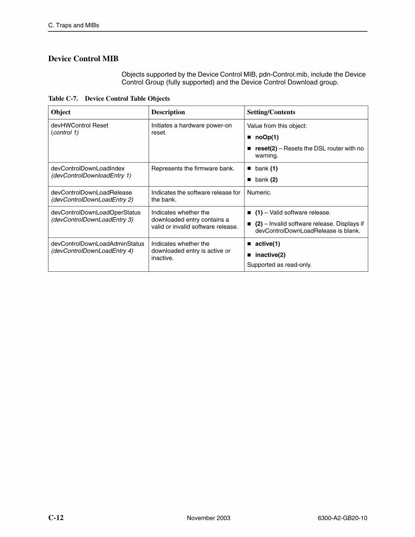
C. Traps and MIBs
C-12 November 2003 6300-A2-GB20-10
Device Control MIB
Objects supported by the Device Control MIB, pdn-Control.mib, include the Device Control Group (fully supported) and the Device Control Download group.
Table C-7. Device Control Table Objects
Object Description Setting/Contents
devHWControl Reset (control 1)
Initiates a hardware power-on reset.
Value from this object:
� noOp(1)
� reset(2) – Resets the DSL router with no warning.
devControlDownLoadIndex(devControlDownloadEntry 1)
Represents the firmware bank. � bank (1)
� bank (2)
devControlDownLoadRelease(devControlDownLoadEntry 2)
Indicates the software release for the bank.
Numeric.
devControlDownLoadOperStatus(devControlDownLoadEntry 3)
Indicates whether the downloaded entry contains a valid or invalid software release.
� (1) – Valid software release.
� (2) – Invalid software release. Displays if devControlDownLoadRelease is blank.
devControlDownLoadAdminStatus (devControlDownLoadEntry 4)
Indicates whether the downloaded entry is active or inactive.
� active(1)
� inactive(2)
Supported as read-only.
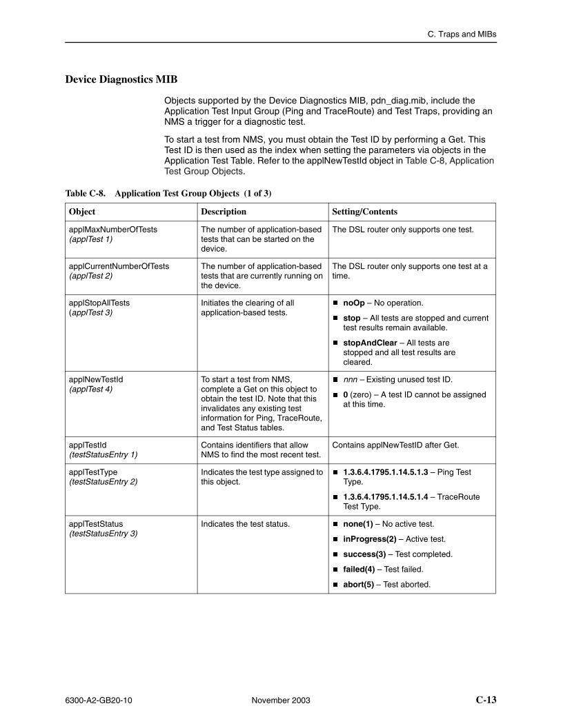
C. Traps and MIBs
6300-A2-GB20-10 November 2003 C-13
Device Diagnostics MIB
Objects supported by the Device Diagnostics MIB, pdn_diag.mib, include the Application Test Input Group (Ping and TraceRoute) and Test Traps, providing an NMS a trigger for a diagnostic test.
To start a test from NMS, you must obtain the Test ID by performing a Get. This Test ID is then used as the index when setting the parameters via objects in the Application Test Table. Refer to the applNewTestId object in Table C-8, Application Test Group Objects.
Table C-8. Application Test Group Objects (1 of 3)
Object Description Setting/Contents
applMaxNumberOfTests(applTest 1)
The number of application-based tests that can be started on the device.
The DSL router only supports one test.
applCurrentNumberOfTests(applTest 2)
The number of application-based tests that are currently running on the device.
The DSL router only supports one test at a time.
applStopAllTests(applTest 3)
Initiates the clearing of all application-based tests.
� noOp – No operation.
� stop – All tests are stopped and current test results remain available.
� stopAndClear – All tests are stopped and all test results are cleared.
applNewTestId(applTest 4)
To start a test from NMS, complete a Get on this object to obtain the test ID. Note that this invalidates any existing test information for Ping, TraceRoute, and Test Status tables.
� nnn – Existing unused test ID.
� 0 (zero) – A test ID cannot be assigned at this time.
applTestId(testStatusEntry 1)
Contains identifiers that allow NMS to find the most recent test.
Contains applNewTestID after Get.
applTestType(testStatusEntry 2)
Indicates the test type assigned to this object.
� 1.3.6.4.1795.1.14.5.1.3 – Ping Test Type.
� 1.3.6.4.1795.1.14.5.1.4 – TraceRoute Test Type.
applTestStatus(testStatusEntry 3)
Indicates the test status. � none(1) – No active test.
� inProgress(2) – Active test.
� success(3) – Test completed.
� failed(4) – Test failed.
� abort(5) – Test aborted.
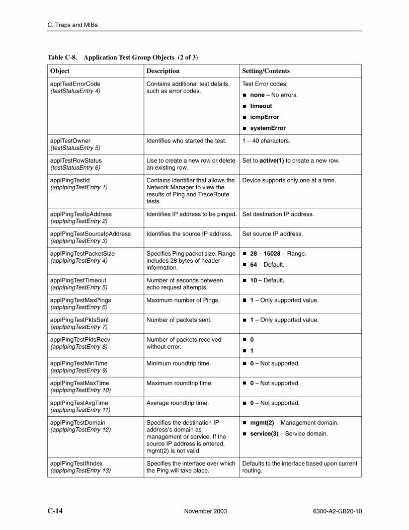
C. Traps and MIBs
C-14 November 2003 6300-A2-GB20-10
applTestErrorCode(testStatusEntry 4)
Contains additional test details, such as error codes.
Test Error codes:
� none – No errors.
� timeout
� icmpError
� systemError
applTestOwner(testStatusEntry 5)
Identifies who started the test. 1 – 40 characters.
applTestRowStatus(testStatusEntry 6)
Use to create a new row or delete an existing row.
Set to active(1) to create a new row.
applPingTestId(applpingTestEntry 1)
Contains identifier that allows the Network Manager to view the results of Ping and TraceRoute tests.
Device supports only one at a time.
applPingTestIpAddress(applpingTestEntry 2)
Identifies IP address to be pinged. Set destination IP address.
applPingTestSourceIpAddress(applpingTestEntry 3)
Identifies the source IP address. Set source IP address.
applPingTestPacketSize(applpingTestEntry 4)
Specifies Ping packet size. Range includes 28 bytes of header information.
� 28 – 15028 – Range.
� 64 – Default.
applPingTestTimeout(applpingTestEntry 5)
Number of seconds between echo request attempts.
� 10 – Default.
applPingTestMaxPings(applpingTestEntry 6)
Maximum number of Pings. � 1 – Only supported value.
applPingTestPktsSent(applpingTestEntry 7)
Number of packets sent. � 1 – Only supported value.
applPingTestPktsRecv(applpingTestEntry 8)
Number of packets received without error.
� 0
� 1
applPingTestMinTime(applpingTestEntry 9)
Minimum roundtrip time. � 0 – Not supported.
applPingTestMaxTime(applpingTestEntry 10)
Maximum roundtrip time. � 0 – Not supported.
applPingTestAvgTime(applpingTestEntry 11)
Average roundtrip time. � 0 – Not supported.
applPingTestDomain(applpingTestEntry 12)
Specifies the destination IP address’s domain as management or service. If the source IP address is entered, mgmt(2) is not valid.
� mgmt(2) – Management domain.
� service(3) – Service domain.
applPingTestIfIndex(applpingTestEntry 13)
Specifies the interface over which the Ping will take place.
Defaults to the interface based upon current routing.
Table C-8. Application Test Group Objects (2 of 3)
Object Description Setting/Contents
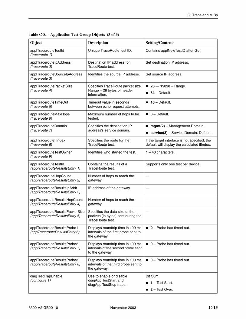
C. Traps and MIBs
6300-A2-GB20-10 November 2003 C-15
applTracerouteTestId(traceroute 1)
Unique TraceRoute test ID. Contains applNewTestID after Get.
applTracerouteIpAddress(traceroute 2)
Destination IP address for TraceRoute test.
Set destination IP address.
applTracerouteSourceIpAddress (traceroute 3)
Identifies the source IP address. Set source IP address.
applTraceroutePacketSize(traceroute 4)
Specifies TraceRoute packet size. Range + 28 bytes of header information.
� 28 — 15028 – Range.
� 64 – Default.
applTracerouteTimeOut(traceroute 5)
Timeout value in seconds between echo request attempts.
� 10 – Default.
applTracerouteMaxHops(traceroute 6)
Maximum number of hops to be tested.
� 8 – Default.
applTracerouteDomain(traceroute 7)
Specifies the destination IP address’s service domain.
� mgmt(2) – Management Domain.
� service(3) – Service Domain. Default.
applTracerouteIfIndex(traceroute 8)
Specifies the route for the TraceRoute test.
If the target interface is not specified, the default will display the calculated ifIndex.
applTracerouteTestOwner(traceroute 9)
Identifies who started the test. 1 – 40 characters.
applTracerouteTestId (applTracerouteResultsEntry 1)
Contains the results of a TraceRoute test.
Supports only one test per device.
applTracerouteHopCount (applTracerouteResultsEntry 2)
Number of hops to reach the gateway.
—
applTracerouteResultsIpAddr(applTracerouteResultsEntry 3)
IP address of the gateway. —
applTracerouteResultsHopCount(applTracerouteResultsEntry 4)
Number of hops to reach the gateway.
—
applTracerouteResultsPacketSize(applTracerouteResultsEntry 5)
Specifies the data size of the packets (in bytes) sent during the TraceRoute test.
—
applTracerouteResultsProbe1(appTracerouteResultsEntry 6)
Displays roundtrip time in 100 ms intervals of the first probe sent to the gateway.
� 0 – Probe has timed out.
applTracerouteResultsProbe2(applTracerouteResultsEntry 7)
Displays roundtrip time in 100 ms intervals of the second probe sent to the gateway.
� 0 – Probe has timed out.
applTracerouteResultsProbe3(applTracerouteResultsEntry 8)
Displays roundtrip time in 100 ms intervals of the third probe sent to the gateway.
� 0 – Probe has timed out.
diagTestTrapEnable(configure 1)
Use to enable or disable diagApplTestStart and diagApplTestStop traps.
Bit Sum.
� 1 – Test Start.
� 2 – Test Over.
Table C-8. Application Test Group Objects (3 of 3)
Object Description Setting/Contents
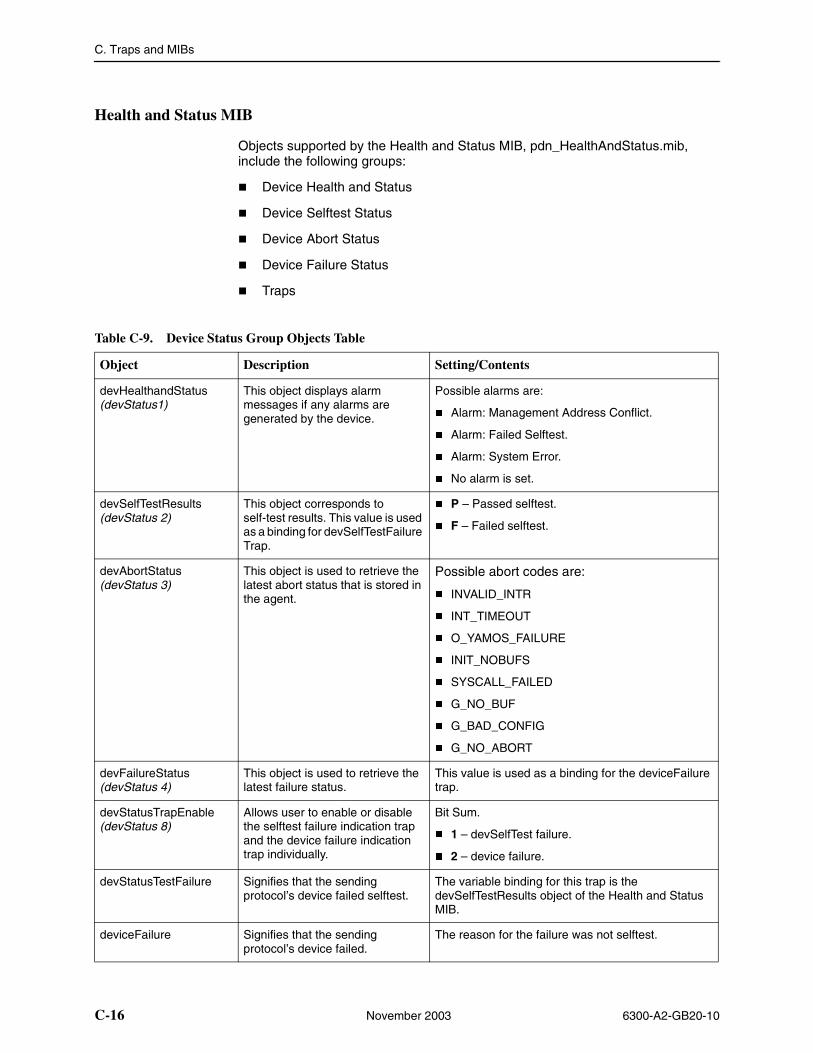
C. Traps and MIBs
C-16 November 2003 6300-A2-GB20-10
Health and Status MIB
Objects supported by the Health and Status MIB, pdn_HealthAndStatus.mib, include the following groups:
� Device Health and Status
� Device Selftest Status
� Device Abort Status
� Device Failure Status
� Traps
Table C-9. Device Status Group Objects Table
Object Description Setting/Contents
devHealthandStatus(devStatus1)
This object displays alarm messages if any alarms are generated by the device.
Possible alarms are:
� Alarm: Management Address Conflict.
� Alarm: Failed Selftest.
� Alarm: System Error.
� No alarm is set.
devSelfTestResults(devStatus 2)
This object corresponds to self-test results. This value is used as a binding for devSelfTestFailure Trap.
� P – Passed selftest.
� F – Failed selftest.
devAbortStatus(devStatus 3)
This object is used to retrieve the latest abort status that is stored in the agent.
Possible abort codes are:
� INVALID_INTR
� INT_TIMEOUT
� O_YAMOS_FAILURE
� INIT_NOBUFS
� SYSCALL_FAILED
� G_NO_BUF
� G_BAD_CONFIG
� G_NO_ABORT
devFailureStatus(devStatus 4)
This object is used to retrieve the latest failure status.
This value is used as a binding for the deviceFailure trap.
devStatusTrapEnable(devStatus 8)
Allows user to enable or disable the selftest failure indication trap and the device failure indication trap individually.
Bit Sum.
� 1 – devSelfTest failure.
� 2 – device failure.
devStatusTestFailure Signifies that the sending protocol’s device failed selftest.
The variable binding for this trap is the devSelfTestResults object of the Health and Status MIB.
deviceFailure Signifies that the sending protocol’s device failed.
The reason for the failure was not selftest.
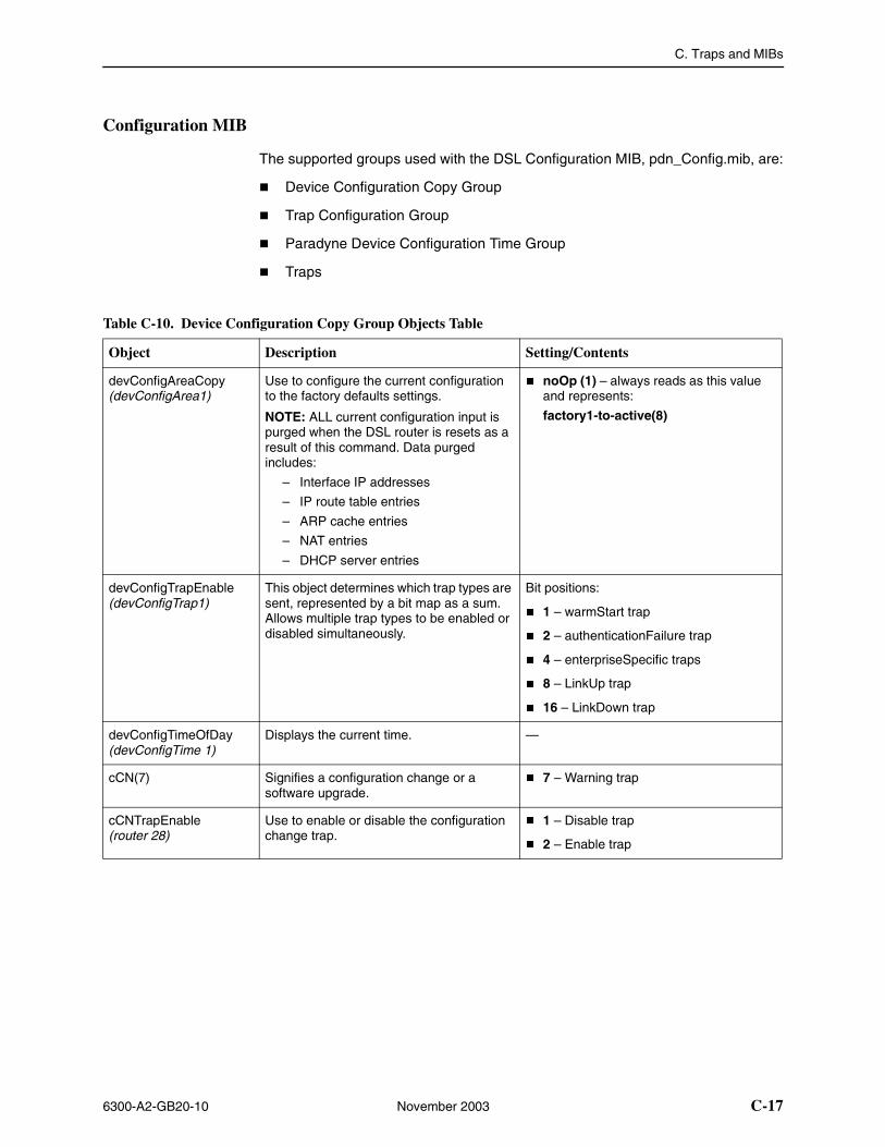
C. Traps and MIBs
6300-A2-GB20-10 November 2003 C-17
Configuration MIB
The supported groups used with the DSL Configuration MIB, pdn_Config.mib, are:
� Device Configuration Copy Group
� Trap Configuration Group
� Paradyne Device Configuration Time Group
� Traps
Table C-10. Device Configuration Copy Group Objects Table
Object Description Setting/Contents
devConfigAreaCopy (devConfigArea1)
Use to configure the current configuration to the factory defaults settings.
NOTE: ALL current configuration input is purged when the DSL router is resets as a result of this command. Data purged includes:
– Interface IP addresses
– IP route table entries
– ARP cache entries
– NAT entries
– DHCP server entries
� noOp (1) – always reads as this value and represents:
factory1-to-active(8)
devConfigTrapEnable (devConfigTrap1)
This object determines which trap types are sent, represented by a bit map as a sum. Allows multiple trap types to be enabled or disabled simultaneously.
Bit positions:
� 1 – warmStart trap
� 2 – authenticationFailure trap
� 4 – enterpriseSpecific traps
� 8 – LinkUp trap
� 16 – LinkDown trap
devConfigTimeOfDay (devConfigTime 1)
Displays the current time. —
cCN(7) Signifies a configuration change or a software upgrade.
� 7 – Warning trap
cCNTrapEnable (router 28)
Use to enable or disable the configuration change trap.
� 1 – Disable trap
� 2 – Enable trap
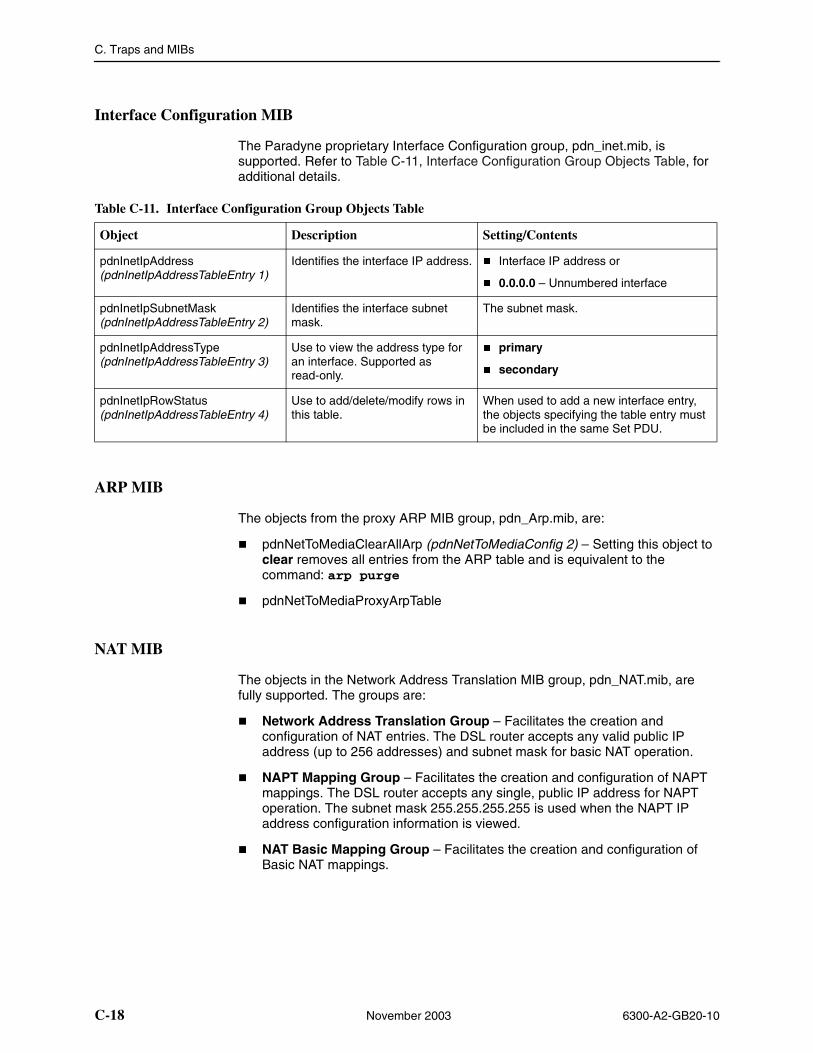
C. Traps and MIBs
C-18 November 2003 6300-A2-GB20-10
Interface Configuration MIB
The Paradyne proprietary Interface Configuration group, pdn_inet.mib, is supported. Refer to Table C-11, Interface Configuration Group Objects Table, for additional details.
ARP MIB
The objects from the proxy ARP MIB group, pdn_Arp.mib, are:
� pdnNetToMediaClearAllArp (pdnNetToMediaConfig 2) – Setting this object to clear removes all entries from the ARP table and is equivalent to the command: arp purge
� pdnNetToMediaProxyArpTable
NAT MIB
The objects in the Network Address Translation MIB group, pdn_NAT.mib, are fully supported. The groups are:
� Network Address Translation Group – Facilitates the creation and configuration of NAT entries. The DSL router accepts any valid public IP address (up to 256 addresses) and subnet mask for basic NAT operation.
� NAPT Mapping Group – Facilitates the creation and configuration of NAPT mappings. The DSL router accepts any single, public IP address for NAPT operation. The subnet mask 255.255.255.255 is used when the NAPT IP address configuration information is viewed.
� NAT Basic Mapping Group – Facilitates the creation and configuration of Basic NAT mappings.
Table C-11. Interface Configuration Group Objects Table
Object Description Setting/Contents
pdnInetIpAddress(pdnInetIpAddressTableEntry 1)
Identifies the interface IP address. � Interface IP address or
� 0.0.0.0 – Unnumbered interface
pdnInetIpSubnetMask(pdnInetIpAddressTableEntry 2)
Identifies the interface subnet mask.
The subnet mask.
pdnInetIpAddressType(pdnInetIpAddressTableEntry 3)
Use to view the address type for an interface. Supported as read-only.
� primary
� secondary
pdnInetIpRowStatus(pdnInetIpAddressTableEntry 4)
Use to add/delete/modify rows in this table.
When used to add a new interface entry, the objects specifying the table entry must be included in the same Set PDU.
C. Traps and MIBs
6300-A2-GB20-10 November 2003 C-19
DHCP MIB
The supported objects in the DHCP Server/Relay MIB, pdn_dhcp.mib, facilitates the creation and configuration of DHCP server table entries. The following groups are supported:
� DHCP Server Configuration Group – Fully supported. One object is clarified below:
— dhcpServerRouterIpAddr (dhcpserv 7) – Enables you to configure the router IP address used by the DHCP server. This address is provided to clients in the DHCP reply message from the DHCP server. If this value is not set, the accepted value is 0.0.0.0.
� DHCP Binding Group – Facilitates the display of DHCP bindings. This group is fully supported.
� DHCP Relay Group – Facilitates the display of DHCP Relay. This group is fully supported. The following clarifies some of the DHCP Relay objects:
— dhcpRelayIpAddr (xdslDhcpRelayAgent 6) – This is the IP address of DHCP server.
— dhcpRelayEnable (xdslDhcpRelayAgent 7) – Use to enable or disable the DHCP relay agent.
— dhcpRelayMaxClients (xdslDhcpRelayAgent 8) – Enables user to specify the number of clients allowed to request IP address assignments from the server.
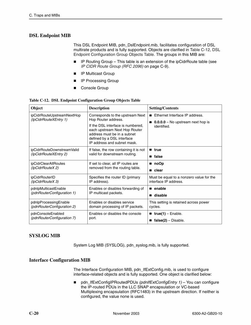
C. Traps and MIBs
C-20 November 2003 6300-A2-GB20-10
DSL Endpoint MIB
This DSL Endpoint MIB, pdn_DslEndpoint.mib, facilitates configuration of DSL multirate products and is fully supported. Objects are clarified in Table C-12, DSL Endpoint Configuration Group Objects Table. The groups in this MIB are:
� IP Routing Group – This table is an extension of the ipCidrRoute table (see IP CIDR Route Group (RFC 2096) on page C-9).
� IP Multicast Group
� IP Processing Group
� Console Group
SYSLOG MIB
System Log MIB (SYSLOG), pdn_syslog.mib, is fully supported.
Interface Configuration MIB
The Interface Configuration MIB, pdn_IfExtConfig.mib, is used to configure interface-related objects and is fully supported. One object is clarified below:
� pdn_IfExtConfigIPRoutedPDUs (pdnIfExtConfigEntry 1) – You can configure the IP-routed PDUs in the LLC SNAP encapsulation or VC-based Multiplexing encapsulation (RFC1483) in the upstream direction. If neither is configured, the value none is used.
Table C-12. DSL Endpoint Configuration Group Objects Table
Object Description Setting/Contents
ipCidrRouteUpstreamNextHop(IpCidrRouteXEntry 1)
Corresponds to the upstream Next Hop Router address.
If the DSL interface is numbered, each upstream Next Hop Router address must be in a subnet defined by a DSL interface IP address and subnet mask.
� Ethernet Interface IP address.
� 0.0.0.0 – No upstream next hop is identified.
ipCidrRouteDownstreamValid(IpCidrRouteXEntry 2)
If false, the row containing it is not valid for downstream routing.
� true
� false
ipCidrClearAllRoutes(IpCidrRouteX 2)
If set to clear, all IP routes are removed from the routing table.
� noOp
� clear
ipCidrRouterID(IpCidrRouteX 3)
Specifies the router ID (primary IP address).
Must be equal to a nonzero value for the interface IP address.
pdnlpMulticastEnable(pdnRouterConfiguration 1)
Enables or disables forwarding of IP multicast packets.
� enable
� disable
pdnlpProcessingEnable(pdnRouterConfiguration 2)
Enables or disables service domain processing of IP packets.
This setting is retained across power cycles.
pdnConsoleEnabled(pdnRouterConfiguration 7)
Enables or disables the console port.
� true(1) – Enable.
� false(2) – Disable.
6300-A2-GB20-10 November 2003 D-1
DDSL Router Terminal Emulation
DSL Router Terminal Emulation
The Command Line Interface is available at the DSL router when the Console cable is connected to a VT100-compatible terminal or a PC running a terminal emulation program. Verify the terminal settings:
� Data rate is set to 19.2 Kbps (19200 bps).
� Character length is set to 8.
� Parity is set to None.
� Stop bits is set to 1.
� Flow control is set to Off or None.
Accessing the List Command Output
Use the list config command to output command strings needed to restore the current running configuration. Output from the List Confg command can be captured to a text file using most terminal emulation programs. Examples of two VT100-compatible programs are provided.
Once the text file is captured, the DSL router can be placed in configuration mode. The text file can be fed back to configure the DSL router.
D. DSL Router Terminal Emulation
D-2 November 2003 6300-A2-GB20-10
Terminal Emulation Programs
Examples of configuring two different terminal emulation programs:
� HyperTerminal – playback feature is accessed through its Transfer menu.
� Procomm+ – playback feature is accessed through its Online menu.
Procedure
To configure the HyperTerminal:
1. Select menu option Transfer → Send Text File.
2. Select File → Properties.
3. In the Properties dialog, select the Settings tab.
4. Set Emulation to VT100.
5. Select the Terminal Setup button and set to 132 column mode.
6. Select OK to exit Terminal Setup.
7. Select the ASCII Setup button.
— Set Line delay to 50 ms.
— Set Character delay to 2 ms.
8. Select OK to exit ASCII Setup.
9. Select OK to exit Properties.
Procedure
To configure Procomm+:
1. Select menu option Online → Send File.
2. In the Send File dialog, set the protocol to ASCII.
3. Select the Setup button.
4. Select the Transfer Protocol button (on the left).
5. Select ASCII in the Current Protocol drop-down box.
— Set delay between Character to 2 ms.
— Set delay between Lines to 2 ms.
6. Check and set Use 13 for Line pace character.
7. Check display text.
8. Save the configuration.
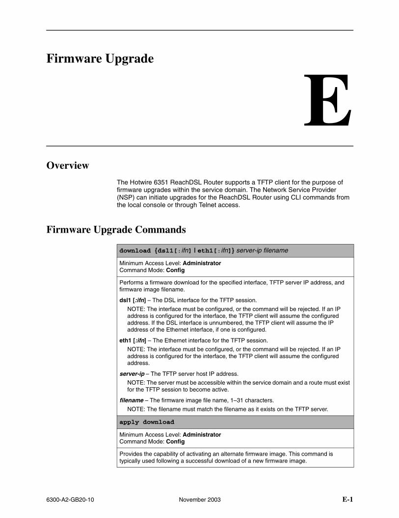
6300-A2-GB20-10 November 2003 E-1
EFirmware Upgrade
Overview
The Hotwire 6351 ReachDSL Router supports a TFTP client for the purpose of firmware upgrades within the service domain. The Network Service Provider (NSP) can initiate upgrades for the ReachDSL Router using CLI commands from the local console or through Telnet access.
Firmware Upgrade Commands
download {dsl1[:ifn] | eth1[:ifn]} server-ip filename
Minimum Access Level: AdministratorCommand Mode: Config
Performs a firmware download for the specified interface, TFTP server IP address, and firmware image filename.
dsl1 [:ifn] – The DSL interface for the TFTP session.
NOTE: The interface must be configured, or the command will be rejected. If an IP address is configured for the interface, the TFTP client will assume the configured address. If the DSL interface is unnumbered, the TFTP client will assume the IP address of the Ethernet interface, if one is configured.
eth1 [:ifn] – The Ethernet interface for the TFTP session.
NOTE: The interface must be configured, or the command will be rejected. If an IP address is configured for the interface, the TFTP client will assume the configured address.
server-ip – The TFTP server host IP address.
NOTE: The server must be accessible within the service domain and a route must exist for the TFTP session to become active.
filename – The firmware image file name, 1–31 characters.
NOTE: The filename must match the filename as it exists on the TFTP server.
apply download
Minimum Access Level: AdministratorCommand Mode: Config
Provides the capability of activating an alternate firmware image. This command is typically used following a successful download of a new firmware image.
E. Firmware Upgrade
E-2 November 2003 6300-A2-GB20-10
Firmware Upgrade Procedures
The NSP can enter CLI commands from the local console or via Telnet to upgrade Hotwire 6351 ReachDSL firmware and activate an alternate firmware image.
Procedure
To upgrade firmware for the Hotwire 6351 ReachDSL Router within the service domain:
1. Log in and enter ADMIN-configuration mode.
2. At the CUSTOMER-CONFIG#> prompt, type the interface for the TFTP session, the TFTP server host IP address, and the firmware image file name.
download {dsl1[:ifn] | eth1[:ifn]} server-ip filename
For example:
download ifn address eth1 155.1.3.254 Paradyne server
3. The command syntax is verified and you are prompted for confirmation:
Downloading will affect user data performance.
Are you sure?
Once you confirm the request, the file transfer begins and you can observe the following:
— The ALM and TST LEDs alternately flash until the file transfer completes.
— The symbol ! is displayed on the CLI for every 10 packets received from the server.
4. Upon completion of the transfer, if the image transferred has the same firmware version as the image in the target flashbank, the download process is complete and the final command response is displayed.
If the transferred image is different, the image is programmed to flash memory. During this programming time (approximately 30 seconds), you can observe the following:
— The ALM and TST LEDs light.
— User data performance is affected.
After flash programming completes, the ALM LED goes off, and the status of the checksum calculation, a final information (or error) message, and the file transfer statistics are displayed:
Accessing TFTP: //server_ip/filename
!!!!!!!!!!!!!!!!!!!!!!!!!!!!!!!!!!!!!!!!!!!!!!!!!!!!!!!!!!!!!!!!!!!!!!!!!!!!!!!!!!!!!!!!!!!!!!!!!!!!!!!!!!!!!!!!!!!!!!!!!!!!!!!!!!!!!!!!!!!!!!!!!!!!!!!!!!!!!!!!!!!!!!!!!!!!!!!!!!!!!!!!!!!!!!!!!!!!!!!!!!!!!!
Checksum OK
1363267 bytes copied in 30 secs (45442 bytes/sec)
E. Firmware Upgrade
6300-A2-GB20-10 November 2003 E-3
NOTE:
A checksum of the file is calculated and verified prior to programming the flashbank. However, a checksum of the active flashbank does not occur until a power-on self-test. If the flashbank was not successfully programmed, the verification of the checksum image in flash memory will fail during self-test and the valid image in the alternate bank will be copied to the active bank.
If the image transferred has the same software revision as the image in the alternate flashbank, an error message displays and the image is not reprogrammed into flash. Also, if an error occurs during the file transfer or flash programming, an error message is displayed.
Procedure
To activate an alternate firmware image following a successful firmware download of a new firmware image:
1. At the CUSTOMER-CONFIG#> prompt, type:
apply download
2. You are then prompted for a command confirmation:
Applying download will result in a system reset.
Are you sure?
Once you confirm the request, the ReachDSL Router will switch from the active flashbank to the alternate flashbank, reset the system and execute the new image. The following message is displayed:
System is being reset
However, if the same firmware image exists in both the active and alternate flashbanks, the unit will not reset and the following message is displayed:
No new firmware to apply

E. Firmware Upgrade
E-4 November 2003 6300-A2-GB20-10
6300-A2-GB20-10 November 2003 IN-1
Index
Symbols!, CLI display for every 10 packets received from the
server during file transfer, E-2?, for determining commands available, 2-5
Numerics802.3, Ethernet frame format, A-5
Aaccess control, 2-1Address Resolution Protocol (ARP), 3-5
show timeout, A-24Administrator access, 2-2alarm
show command, 6-1, A-24ARP, 3-5
show command, A-24table, A-9
autologout, 2-8
Bbasic
NATconfiguring, A-11deleting static mapping, A-13for DHCP server, 4-12network configuration, 4-4show NAT command, A-28
network configuration, 4-2bridge
clearing statistics, A-23commands, A-8mode, 3-2show command, A-25statistics, 5-3, A-31
reasons for discarded frames, 5-7
Cclearing statistics, 5-3
command, A-23
Command Line Interface (CLI)access, 2-3capability, A-1command recall, A-2conventions used in command syntax, A-2navigating, A-2shortcuts, B-3
commandsavailable for access level, 2-5bridge, A-8DHCP relay agent, A-16IP packet processing, A-17PPPoE, A-18show, A-24Telnet, A-21
configurationbasic
bridging, 4-2NAT, 4-4routing, 4-3
DHCPRelay with Proxy ARP, 4-11server PPPoe Client with NAPT, 4-13server with basic NAT, 4-12
downstream router, 4-14–4-15dynamic host protocol (DHCP), A-14factory default settings, B-1hub, 3-2IP passthrough, 4-15NAPT, 4-6overview, 3-1unnumbered DSL interface with Proxy ARP, 4-10
configureterminal, 2-3
consoleaccess, 2-2show command, A-25
conventions used in command syntax, A-2core
network, 3-13router, 3-3
createdestination ip route, A-7upstream eth1 IP route, A-8
customer, system identity prompt, 2-3

Index
IN-2 November 2003 6300-A2-GB20-10
Ddata rates for DSL routers, 1-3default gateway, 4-10–4-11delete
destination IP route, A-7upstream eth1 IP route, A-8
device restart, 6-1DHCP (Dynamic Host Configuration Protocol)
relay network configuration, 4-11server, 3-9
commands, A-14network configuration, 4-12–4-13with basic NAT configuration, 4-12–4-13
show commands, A-26diagnostics, 6-1disable
console access, 2-2discarded data, reasons, 5-4DIX frame format, 3-2domain
name system (DNS), A-15statistics, A-31
downstream router configuration example, 4-14DSL
access system, 1-1router
access, 2-1configuration examples, 4-1terminal emulation, D-1
show interface link status, A-27Sourcebook, 1-4
DSL interface, 3-1statistics, 5-3, A-31
reasons for discarded frames, 5-5dsl1, 3-1
statistics, 5-3
Eenable
Administrator access, 2-2console access, 2-2
encapsulation, 3-2RFC 1483, A-5
Enterprise MIBs, C-11eth1, 3-2
statistics, 5-3Ethernet
frame format command, A-5interface, 3-2show interface link status, A-27statistics, 5-3, A-30
reasons for discarded frames, 5-4
events in SYSLOG, 6-4exiting the system, 2-7
Ffactory defaults, B-1filtering
IP, 3-11router, 3-11
firmware upgradecommands, E-1procedures, E-2
frameEthernet format, A-5
Ggateway
default, 4-10–4-11global network, 3-7glossary, ix
Hhandshake failure alarm, A-24help for current access level, 2-5hub configuration, 3-2
IICMP, 1-3, 3-1
sending an echo request, 6-5identifiers for interfaces, 3-2identifying the link between the router and device, 6-7IDSL
6301 router, 1-26302 router, 1-2cards, 1-2
IEEE 802.3 frame format, 3-2interface
clearing statistics, A-23DSL, 3-1Ethernet, 3-2identifiers, 3-2IP address
commands, A-6numbered DSL or Ethernet scenario, 3-3show, 5-3
command, A-27statistics, 5-3status, 5-3unnumbered configuration, 4-10
Internet Control Message Protocol (ICMP), 3-1

Index
6300-A2-GB20-10 November 2003 IN-3
IPaddress
assignments for service domain, 3-2interface and service domain, A-6syslog, 6-3
filtering, 3-11options processing, 3-8passthrough, example, 4-15passthrough, in ppp command, A-18processing
clearing statistics, A-23statistics, 5-3, A-31statistics, reasons for discarded packets, 5-6
routepurge all, A-8
routing, 3-4
LLAN extension configuration, 4-10learning the path of packets, 6-7leasetime
DHCP server, A-14settings, A-15
LED status, 5-2levels
of access to the DSL router, 2-5of SYSLOG messages, 6-4
linkLogical Control (LLC) encapsulation, A-5show interface status, A-27
list command, 2-6for command line output, D-1
LLC, A-5local console access, 2-2log
show system, 6-2, A-32system, 6-2
events, 6-2Logical Link Control (LLC) encapsulation, A-5login ID, 2-3
MMAC address
in ARP table, A-9management
domain statistics, A-31mapping
NAT function, A-13message
in SYSLOG, 6-4in syslog, 6-5
MIB compliance, C-3
MIB IIIP Group, C-8System Group, C-4
modebridge, 3-2router, 3-2Standard, 3-14Standard or VNET, 3-6Standard vs. VNET, 3-13
monitoring the router, 5-1multiplexing, A-5
Nname, DHCP server’s domain, A-15nameserver, A-14NAPT, 3-7
configuring, A-11network configuration, 4-6show NAT command, A-28simultaneous NAT, 3-8, 4-8
NAT, 3-7basic, 3-7, 4-4command line, A-11DHCP server
network configuration, 4-12show command, A-28simultaneous NAPT, 3-8, 4-8supported applications and protocols, 3-8
navigating the router’s CLI, A-2Network Address
Port Translation (NAPT/PAT), 3-8Translation (NAT), 3-7
Network Management System (NMS), C-1new user setup, 2-3next hop router, 3-3numbered interface scenario, 3-3
OOperator access, 2-2output of show commands, A-24
Ppassthrough, IP, 4-15, A-18password, 2-3PAT (Port Address Translation), 1-3, 3-7PDUs (Protocol Data Units), A-5
routed vs. bridged, 3-13performance statistics, 5-3Ping
command, 6-5message, 6-7results, 6-6
POTS, with 6371 DSL router, 1-1

Index
IN-4 November 2003 6300-A2-GB20-10
PPPauthentication, A-19IP interface and address assignment, A-18–A-19reasons for discarded frames, 5-8statistics, A-32user name, A-19–A-20
PPPoEClient configuration example, 4-13client support, 3-14configuration, A-18–A-19statistics, 5-7, A-32
primaryinterface
status, A-27IP address, A-6
printing command line input, D-1processing IP packets, A-17protocol
Address Resolution (ARP), A-9ARP, A-9Data Units (PDUs), 3-13, A-5Dynamic Host Configuration (DHCP), A-14IP and ICMP, 3-1PDU, A-5spanning-tree, A-9UDP, TCP, A-12–A-13
Proxy ARP, 3-6DHCP relay
network configuration, 4-11network configuration, 4-10
public network, 3-7purge
all IP routing table entries, A-8ARP, A-10NAT, A-14
RRADSL
6371 router, 1-2cards, 1-2
ReachDSL6351 router, 1-2cards, 1-2LEDs, 5-2
reasons for discarded data, 5-4relay agent
commands, A-16DHCP, 4-11
restart device, 6-1results, show commands, A-24
RFC1042, 3-21483, 3-5–3-6, 3-13
encapsulation command, A-51631, 3-72131, 3-9–3-102132, 3-9791, 3-1792, 3-1826, 3-5950, 3-1
route, show command, A-27routed vs. bridged PDUs, 3-13router
6301 IDSL, 1-26302 IDSL, 1-26341 SDSL, 1-26342 SDSL, 1-26351 ReachDSL, 1-26371 RADSL, 1-2DHCP server, A-15downstream configuration, 4-14filtering, 3-11ID, 3-2, A-27
IP address, A-6mode, 3-2
routingIP, 3-4table, 3-4
SSDSL
6341 router, 1-26342 router, 1-2cards, 1-2
security, 3-11selftest results, A-24, A-33sending an echo request (ping), 6-5server
DHCP, 3-9, 4-12–4-13commands, A-14
service domainIP address
assignments, 3-2commands, A-6
statistics, A-31service subscriber, 1-4shortcuts for command line, B-3
Index
6300-A2-GB20-10 November 2003 IN-5
showalarms, 6-1arp command, 3-6bridge, A-25commands, A-24console, A-25DHCP relays and servers, A-26interface, 5-3NAT basic and NAPT configurations, A-28PPPoE, A-29PPPoE configuration, A-29spanning-tree topology, A-29statistics, 5-3system log and system information, 6-2, A-32traps, A-33
show commands forinterface status, 5-3statistics, 5-3
Simple Network Management Protocol (SNMP), C-1agent overview, C-1
simultaneous NAT and NAPT, 4-8SNAP encapsulation, 3-2spanning-tree
show command, A-29standard
MIBs, C-3mode, 3-6, 3-13
static mapping, 3-7statistics
bridge, A-31clearing, 5-3, A-23DSL, A-31Ethernet, A-30IP processing, A-31performance, 5-3PPP, A-32PPPoE, A-32show, 5-3TFTP, A-32
statusinterfaces, 5-3LED, 5-2
syntax, conventions used in commands, A-2syslog, 6-1–6-2
enable, 6-2events, 6-4IP address, 6-3message display, 6-5show command, 6-2, A-32
systemID, A-33identity, 2-3, 2-6log, 6-1–6-2
TTelnet access, 2-1, 2-4Telnet commands, A-21terminal emulation settings, D-1test, Ping results, 6-6TFTP statistics, A-32timeout for show ARP, A-24topology, show spanning-tree, A-29TraceRoute, 6-7Transmission Control Protocol (TCP), A-12–A-13traps, C-2
show command, A-33troubleshooting, 6-1
Uunnumbered DSL interface
IP address, A-6network configuration, 4-10scenario, 3-3
upstream static route, creating or deleting, A-8User Datagram Protocol (UDP), A-12–A-13user login, 2-3
VVirtual Circuit (VC) multiplexing, A-5VNET mode, 3-6, 3-13

Index
IN-6 November 2003 6300-A2-GB20-10