hotwire m/sdsl standalone termination...
TRANSCRIPT

HOTWIRE M/SDSL STANDALONE
TERMINATION UNITSMODELS 7974-A2, 7975-A2,
AND 7976-A2USER’S GUIDE
Document No. 7900-A2-GB21-00
August 2000

Printed on recycled paper
A 7900-A2-GB21-00August 2000
Copyright 2000 Paradyne Corporation.All rights reserved.Printed in U.S.A.
Notice
This publication is protected by federal copyright law. No part of this publication may be copied or distributed,transmitted, transcribed, stored in a retrieval system, or translated into any human or computer language in any formor by any means, electronic, mechanical, magnetic, manual or otherwise, or disclosed to third parties without theexpress written permission of Paradyne Corporation, 8545 126th Ave. N., Largo, FL 33773.
Paradyne Corporation makes no representation or warranties with respect to the contents hereof and specificallydisclaims any implied warranties of merchantability or fitness for a particular purpose. Further, Paradyne Corporationreserves the right to revise this publication and to make changes from time to time in the contents hereof withoutobligation of Paradyne Corporation to notify any person of such revision or changes.
Changes and enhancements to the product and to the information herein will be documented and issued as a newrelease to this manual.
Warranty, Sales, Service, and Training Information
Contact your local sales representative, service representative, or distributor directly for any help needed. Foradditional information concerning warranty, sales, service, repair, installation, documentation, training, distributorlocations, or Paradyne worldwide office locations, use one of the following methods:
Internet: Visit the Paradyne World Wide Web site at www.paradyne.com. (Be sure to register your warranty at www.paradyne.com/warranty.)
Telephone: Call our automated system to receive current information by fax or to speak with a company representative.
— Within the U.S.A., call 1-800-870-2221— Outside the U.S.A., call 1-727-530-2340
Document Feedback
We welcome your comments and suggestions about this document. Please mail them to Technical Publications,Paradyne Corporation, 8545 126th Ave. N., Largo, FL 33773, or send e-mail to [email protected]. Includethe number and title of this document in your correspondence. Please include your name and phone number if youare willing to provide additional clarification.
Trademarks
ACCULINK, COMSPHERE, FrameSaver, Hotwire, and NextEDGE are registered trademarks of ParadyneCorporation. MVL, OpenLane, Performance Wizard, and TruePut are trademarks of Paradyne Corporation. All otherproducts and services mentioned herein are the trademarks, service marks, registered trademarks, or registeredservice marks of their respective owners.

i7900-A2-GB21-00 August 2000
Contents
About This Guide Document Purpose and Intended Audience vii. . . . . . . . . . . . . . . . . . . . . . . . .
Document Summary vii. . . . . . . . . . . . . . . . . . . . . . . . . . . . . . . . . . . . . . . . . . . . .
Product-Related Documents viii. . . . . . . . . . . . . . . . . . . . . . . . . . . . . . . . . . . . . .
1 About the Hotwire Standalone Termination Unit M/SDSL Overview 1-1. . . . . . . . . . . . . . . . . . . . . . . . . . . . . . . . . . . . . . . . . . . . . .
Hotwire Standalone Termination Unit Features 1-2. . . . . . . . . . . . . . . . . . . . . .
Network Configuration 1-3. . . . . . . . . . . . . . . . . . . . . . . . . . . . . . . . . . . . . . . . . . .
Front Panel LED Status Indicators 1-4. . . . . . . . . . . . . . . . . . . . . . . . . . . . . . . . .
Rear Panel Interface Connections 1-5. . . . . . . . . . . . . . . . . . . . . . . . . . . . . . . . .
SNMP Management Capabilities 1-6. . . . . . . . . . . . . . . . . . . . . . . . . . . . . . . . . .
Management Information Base (MIB) Support 1-6. . . . . . . . . . . . . . . . . . .
SNMP Trap Support 1-7. . . . . . . . . . . . . . . . . . . . . . . . . . . . . . . . . . . . . . . . .
2 Using the Asynchronous Terminal Interface User Interface Access 2-1. . . . . . . . . . . . . . . . . . . . . . . . . . . . . . . . . . . . . . . . . . .
Communication Port Settings 2-1. . . . . . . . . . . . . . . . . . . . . . . . . . . . . . . . . . . . .
Initiating an ATI Session 2-2. . . . . . . . . . . . . . . . . . . . . . . . . . . . . . . . . . . . . . . . .
Menu Tree 2-4. . . . . . . . . . . . . . . . . . . . . . . . . . . . . . . . . . . . . . . . . . . . . . . . . . . . .
Screen Work Areas 2-5. . . . . . . . . . . . . . . . . . . . . . . . . . . . . . . . . . . . . . . . . . . . .
Navigating the Screens 2-6. . . . . . . . . . . . . . . . . . . . . . . . . . . . . . . . . . . . . . . . . .
Keyboard Keys 2-6. . . . . . . . . . . . . . . . . . . . . . . . . . . . . . . . . . . . . . . . . . . . . .
Screen Function Keys 2-7. . . . . . . . . . . . . . . . . . . . . . . . . . . . . . . . . . . . . . . .
Switching Between Screen Work Areas 2-8. . . . . . . . . . . . . . . . . . . . . . . .
Ending an ATI Session 2-8. . . . . . . . . . . . . . . . . . . . . . . . . . . . . . . . . . . . . . . . . . .

Contents
ii 7900-A2-GB21-00August 2000
3 Initial Startup and Configuration Overview 3-1. . . . . . . . . . . . . . . . . . . . . . . . . . . . . . . . . . . . . . . . . . . . . . . . . . . . . .
Connecting Power 3-2. . . . . . . . . . . . . . . . . . . . . . . . . . . . . . . . . . . . . . . . . . . . . .
Connecting to an Optional External DC Power Source 3-2. . . . . . . . . . . .
Connecting to the Network 3-3. . . . . . . . . . . . . . . . . . . . . . . . . . . . . . . . . . . . . . .
Connecting to a DTE 3-3. . . . . . . . . . . . . . . . . . . . . . . . . . . . . . . . . . . . . . . . . . . .
Connecting to a System Terminal 3-4. . . . . . . . . . . . . . . . . . . . . . . . . . . . . . . . .
Entering Identity Information 3-5. . . . . . . . . . . . . . . . . . . . . . . . . . . . . . . . . . . . . .
Choosing a Configuration Method 3-7. . . . . . . . . . . . . . . . . . . . . . . . . . . . . . . . .
Configuring the Unit Using the Configuration Menus 3-7. . . . . . . . . . . . . . . . .
Accessing and Displaying Configuration Options 3-8. . . . . . . . . . . . . . . . . . . .
Configuration Edit/Display 3-9. . . . . . . . . . . . . . . . . . . . . . . . . . . . . . . . . . . . . . . .
Configuration Loader 3-11. . . . . . . . . . . . . . . . . . . . . . . . . . . . . . . . . . . . . . . . . . . .
Saving Configuration Options 3-13. . . . . . . . . . . . . . . . . . . . . . . . . . . . . . . . . . . . .
Downloading Code 3-14. . . . . . . . . . . . . . . . . . . . . . . . . . . . . . . . . . . . . . . . . . . . . .
Disabling AutoRate 3-16. . . . . . . . . . . . . . . . . . . . . . . . . . . . . . . . . . . . . . . . . . . . . .
Resetting AutoRate 3-16. . . . . . . . . . . . . . . . . . . . . . . . . . . . . . . . . . . . . . . . . . . . .
4 Configuring the Unit Using the Internal Switches Overview 4-1. . . . . . . . . . . . . . . . . . . . . . . . . . . . . . . . . . . . . . . . . . . . . . . . . . . . . .
Configuring the Unit Using the Internal Switches 4-2. . . . . . . . . . . . . . . . . . . .
Switchpack Locations 4-3. . . . . . . . . . . . . . . . . . . . . . . . . . . . . . . . . . . . . . . .
Switchpack Definitions for Model 7974 4-4. . . . . . . . . . . . . . . . . . . . . . . . .
Switchpack Definitions for Model 7975 4-6. . . . . . . . . . . . . . . . . . . . . . . . .
Switchpack Definitions for Model 7976 4-9. . . . . . . . . . . . . . . . . . . . . . . . .
5 IP Addressing Selecting an IP Addressing Scheme 5-1. . . . . . . . . . . . . . . . . . . . . . . . . . . . . . .
Configurations Not Running IP Conservative Software 5-1. . . . . . . . . . .
All Configurations 5-1. . . . . . . . . . . . . . . . . . . . . . . . . . . . . . . . . . . . . . . . . . . .
IP Addressing Example 5-2. . . . . . . . . . . . . . . . . . . . . . . . . . . . . . . . . . . . . . . . . .
Contents
iii7900-A2-GB21-00 August 2000
6 Security Overview 6-1. . . . . . . . . . . . . . . . . . . . . . . . . . . . . . . . . . . . . . . . . . . . . . . . . . . . . .
ATI Access Levels 6-2. . . . . . . . . . . . . . . . . . . . . . . . . . . . . . . . . . . . . . . . . . . . . .
Creating a Login 6-3. . . . . . . . . . . . . . . . . . . . . . . . . . . . . . . . . . . . . . . . . . . . . . . .
Deleting a Login 6-5. . . . . . . . . . . . . . . . . . . . . . . . . . . . . . . . . . . . . . . . . . . . . . . .
Resetting the Unit’s COM Port or Factory Defaults 6-6. . . . . . . . . . . . . . . . . . .
Controlling SNMP Access 6-7. . . . . . . . . . . . . . . . . . . . . . . . . . . . . . . . . . . . . . . .
Assigning SNMP Community Names and Access Types 6-7. . . . . . . . . .
Limiting SNMP Access through the IP Addresses of the Managers 6-7.
7 Monitoring and Troubleshooting What to Monitor 7-1. . . . . . . . . . . . . . . . . . . . . . . . . . . . . . . . . . . . . . . . . . . . . . . . .
Viewing System and Test Status 7-2. . . . . . . . . . . . . . . . . . . . . . . . . . . . . . . . . .
Health and Status Messages 7-3. . . . . . . . . . . . . . . . . . . . . . . . . . . . . . . . . .
Self-Test Results Messages 7-5. . . . . . . . . . . . . . . . . . . . . . . . . . . . . . . . . . .
Test Status Messages 7-6. . . . . . . . . . . . . . . . . . . . . . . . . . . . . . . . . . . . . . . .
Entry Response Messages 7-7. . . . . . . . . . . . . . . . . . . . . . . . . . . . . . . . . . . . . . .
Viewing Network Error Statistics 7-9. . . . . . . . . . . . . . . . . . . . . . . . . . . . . . . . . .
Viewing Network Performance Statistics 7-11. . . . . . . . . . . . . . . . . . . . . . . . . . .
Viewing DSX-1 Performance Statistics (Model 7974) 7-13. . . . . . . . . . . . . . . . . . . . . . . . . . . . . . . . . . . . . . . . . . . . . . . . . . .
Viewing G.703 Performance Statistics(Model 7976) 7-15. . . . . . . . . . . . . . . . . . . . . . . . . . . . . . . . . . . . . . . . . . . . . . . . . . .
Using the Display LEDs Screen 7-17. . . . . . . . . . . . . . . . . . . . . . . . . . . . . . . . . . .
Hotwire Standalone Termination Unit LEDs 7-18. . . . . . . . . . . . . . . . . . . . . . . . .
Troubleshooting 7-19. . . . . . . . . . . . . . . . . . . . . . . . . . . . . . . . . . . . . . . . . . . . . . . . .

Contents
iv 7900-A2-GB21-00August 2000
8 Testing Accessing the Test Menu 8-1. . . . . . . . . . . . . . . . . . . . . . . . . . . . . . . . . . . . . . . . .
Running Network Tests 8-3. . . . . . . . . . . . . . . . . . . . . . . . . . . . . . . . . . . . . . . . . .
Network Line Loopback 8-4. . . . . . . . . . . . . . . . . . . . . . . . . . . . . . . . . . . . . .
Remote Network Send Line Loopback 8-5. . . . . . . . . . . . . . . . . . . . . . . . .
DSX-1 Tests (Model 7974) 8-6. . . . . . . . . . . . . . . . . . . . . . . . . . . . . . . . . . . . . . .
Network Repeater Loopback (DSX-1) 8-7. . . . . . . . . . . . . . . . . . . . . . . . . .
DSX-1 DTE Loopback 8-8. . . . . . . . . . . . . . . . . . . . . . . . . . . . . . . . . . . . . . . .
SYNC Data Port Tests (Model 7975) 8-9. . . . . . . . . . . . . . . . . . . . . . . . . . . . . . .
Data Terminal Loopback 8-10. . . . . . . . . . . . . . . . . . . . . . . . . . . . . . . . . . . . . .
Data Channel Loopback 8-11. . . . . . . . . . . . . . . . . . . . . . . . . . . . . . . . . . . . . .
Send Remote Data Channel Loopback 8-12. . . . . . . . . . . . . . . . . . . . . . . . .
G.703 Tests (Model 7976) 8-13. . . . . . . . . . . . . . . . . . . . . . . . . . . . . . . . . . . . . . . .
Network Repeater Loopback (G.703) 8-14. . . . . . . . . . . . . . . . . . . . . . . . . .
G.703 DTE Loopback 8-15. . . . . . . . . . . . . . . . . . . . . . . . . . . . . . . . . . . . . . . .
Device Tests 8-16. . . . . . . . . . . . . . . . . . . . . . . . . . . . . . . . . . . . . . . . . . . . . . . . . . .
Lamp Test 8-16. . . . . . . . . . . . . . . . . . . . . . . . . . . . . . . . . . . . . . . . . . . . . . . . . .
Ending an Active Test 8-17. . . . . . . . . . . . . . . . . . . . . . . . . . . . . . . . . . . . . . . . . . . .
Telco-Initiated Tests (Model 7974) 8-18. . . . . . . . . . . . . . . . . . . . . . . . . . . . . . . . .
Telco-Initiated Line Loopback 8-18. . . . . . . . . . . . . . . . . . . . . . . . . . . . . . . . .
Telco-Initiated Payload Loopback 8-19. . . . . . . . . . . . . . . . . . . . . . . . . . . . . .
Telco-Initiated Remote Line Loopback 8-19. . . . . . . . . . . . . . . . . . . . . . . . . .
A Configuration Options Overview A-1. . . . . . . . . . . . . . . . . . . . . . . . . . . . . . . . . . . . . . . . . . . . . . . . . . . . . .
Network Interface Options Menu A-2. . . . . . . . . . . . . . . . . . . . . . . . . . . . . . . . . .
DSX-1 Interface Options for Model 7974 A-6. . . . . . . . . . . . . . . . . . . . . . . . . . .
Synchronous Data Port Options for Model 7975 A-8. . . . . . . . . . . . . . . . . . . . .
G.703 Interface Options for Model 7976 A-11. . . . . . . . . . . . . . . . . . . . . . . . . . . .
System Options Menu A-13. . . . . . . . . . . . . . . . . . . . . . . . . . . . . . . . . . . . . . . . . . .
Communication Port A-15. . . . . . . . . . . . . . . . . . . . . . . . . . . . . . . . . . . . . . . . . . . . .
Management and Communication Options Menu A-19. . . . . . . . . . . . . . . . . . . .
Telnet Session Options A-19. . . . . . . . . . . . . . . . . . . . . . . . . . . . . . . . . . . . . . .
Communication Protocol Options A-21. . . . . . . . . . . . . . . . . . . . . . . . . . . . . .
General SNMP Management Options A-24. . . . . . . . . . . . . . . . . . . . . . . . . .
SNMP NMS Security Options A-26. . . . . . . . . . . . . . . . . . . . . . . . . . . . . . . . .
SNMP Traps Options A-28. . . . . . . . . . . . . . . . . . . . . . . . . . . . . . . . . . . . . . . .

Contents
v7900-A2-GB21-00 August 2000
B Standards Compliance for SNMP Traps SNMP Traps B-1. . . . . . . . . . . . . . . . . . . . . . . . . . . . . . . . . . . . . . . . . . . . . . . . . . .
ifIndex Variable Binding B-1. . . . . . . . . . . . . . . . . . . . . . . . . . . . . . . . . . . . . . . . . .
warmStart B-2. . . . . . . . . . . . . . . . . . . . . . . . . . . . . . . . . . . . . . . . . . . . . . . . . . . . . .
authenticationFailure B-2. . . . . . . . . . . . . . . . . . . . . . . . . . . . . . . . . . . . . . . . . . . .
linkUp and linkDown B-3. . . . . . . . . . . . . . . . . . . . . . . . . . . . . . . . . . . . . . . . . . . . .
Enterprise-Specific Traps B-5. . . . . . . . . . . . . . . . . . . . . . . . . . . . . . . . . . . . . . . .
C Cables and Pin Assignments Overview C-1. . . . . . . . . . . . . . . . . . . . . . . . . . . . . . . . . . . . . . . . . . . . . . . . . . . . . .
Power Input Connector C-2. . . . . . . . . . . . . . . . . . . . . . . . . . . . . . . . . . . . . . . . . .
COM Port Connector C-3. . . . . . . . . . . . . . . . . . . . . . . . . . . . . . . . . . . . . . . . . . . .
COM Port-to-PC Cable C-4. . . . . . . . . . . . . . . . . . . . . . . . . . . . . . . . . . . . . . . . . .
COM Port-to-LAN Adapter Cable C-5. . . . . . . . . . . . . . . . . . . . . . . . . . . . . . . . . .
DSX-1/G.703 Network Interface C-6. . . . . . . . . . . . . . . . . . . . . . . . . . . . . . . . . . .
EIA-530-A Port C-7. . . . . . . . . . . . . . . . . . . . . . . . . . . . . . . . . . . . . . . . . . . . . . . . .
EIA-530-A-to-X.21 Interface C-8. . . . . . . . . . . . . . . . . . . . . . . . . . . . . . . . . . . . . .
EIA-530-A-to-RS-449 Interface C-10. . . . . . . . . . . . . . . . . . . . . . . . . . . . . . . . . . .
EIA-530-A-to-V.35 Interface C-12. . . . . . . . . . . . . . . . . . . . . . . . . . . . . . . . . . . . . .
DSL Network Interface Cable C-14. . . . . . . . . . . . . . . . . . . . . . . . . . . . . . . . . . . . .
D Technical Specifications
Glossary
Index

Contents
vi 7900-A2-GB21-00August 2000
This page intentionally left blank.
vii7900-A2-GB21-00 August 2000
About This Guide
Document Purpose and Intended Audience
This guide contains information needed to set up, configure, and operate theHotwire Multirate Symmetric Digital Subscriber Line (M/SDSL) StandaloneTermination Unit, Models 7974-A2, 7975-A2 and 7976-A2, and is intended forinstallers and operators.
Document Summary
Section Description
Chapter 1 About the Hotwire Standalone Termination Unit. Describesthe unit’s features and capabilities.
Chapter 2 Using the Asynchronous Terminal Interface. Providesinstructions for accessing the user interface and navigatingthrough the screens.
Chapter 3 Initial Startup and Configuration. Provides procedures forsetting up the user interface and for configuring the unitusing the asynchronous terminal interface.
Chapter 4 Configuring the Unit Using the Internal Switches. Providesprocedures for configuring the unit using the internalswitches instead of the asynchronous terminal interface.
Chapter 5 IP Addressing. Provides information and examplesregarding IP addresses.
Chapter 6 Security. Presents procedures for creating a login, settingthe effective access levels, and controlling SNMP access.
Chapter 7 Monitoring and Troubleshooting. Describes using the LEDs,status messages, and network statistics to monitor the unitand detect and correct problems.
Chapter 8 Testing. Provides information about available tests and testsetup.
About This Guide
viii 7900-A2-GB21-00August 2000
Section Description
Appendix A Configuration Options. Contains all configuration options,possible settings, and default settings.
Appendix B Standards Compliance for SNMP Traps. Contains SNMPtrap compliance information.
Appendix C Cables and Pin Assignments. Contains connector andinterface information.
Appendix D Technical Specifications. Contains physical and regulatoryspecifications, network and port interfaces, powerconsumption values, and accessory part numbers.
Glossary Defines acronyms and terms used in this document.
Index Lists key terms, acronyms, concepts, and sections inalphabetical order.
Product-Related Documents
Document Number Document Title
7900-A2-GN11 Hotwire M/SDSL Standalone Termination Units,Models 7974-A2, 7975-A2, and 7976-A2, InstallationInstructions
8700-A2-GB20 Hotwire M/SDSL and HDSL2 Termination Units,Models 8747, 8777, and 8779, User’s Guide
8700-A2-GB25 Hotwire M/SDSL and M/HDSL Termination Units,Models 8775 and 8785, User’s Guide
Contact your sales or service representative to order additional productdocumentation.
Paradyne documents are also available on the World Wide Web atwww.paradyne.com. Select Library → Technical Manuals.
1-17900-A2-GB21-00 August 2000
About the Hotwire StandaloneTermination Unit
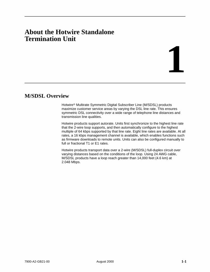
1M/SDSL Overview
Hotwire Multirate Symmetric Digital Subscriber Line (M/SDSL) productsmaximize customer service areas by varying the DSL line rate. This ensuressymmetric DSL connectivity over a wide range of telephone line distances andtransmission line qualities.
Hotwire products support autorate. Units first synchronize to the highest line ratethat the 2-wire loop supports, and then automatically configure to the highestmultiple of 64 kbps supported by that line rate. Eight line rates are available. At allrates, a 16 kbps management channel is available, which enables functions suchas firmware downloads to remote units. Units can also be configured manually tofull or fractional T1 or E1 rates.
Hotwire products transport data over a 2-wire (M/SDSL) full-duplex circuit overvarying distances based on the conditions of the loop. Using 24 AWG cable,M/SDSL products have a loop reach greater than 14,000 feet (4.6 km) at 2.048 Mbps.

About the Hotwire Standalone Termination Unit
1-2 7900-A2-GB21-00August 2000
Hotwire Standalone Termination Unit Features
The Hotwire Standalone Termination Unit is an endpoint for the chassis-mountedHotwire 877x Termination Unit housed in the Hotwire 8600 Series or 8800 SeriesDigital Subscriber Line Access Multiplexer (DSLAM).
Two Hotwire Standalone Termination Units can also be configured to operate in acentral office line termination unit (LTU) to customer premises networktermination unit (NTU) environment.
The termination unit offers these standard features:
Embedded Operations Channel (EOC). Provides remote SNMP Traps,Telnet session capability over the M/SDSL link, and download capabilities.
Asynchronous Terminal Interface (ATI). Provides a menu-drivenVT100-compatible terminal interface for configuring and managing thetermination unit locally or remotely by Telnet session.
Local Management (standalone unit). Provides local management using a:
— Terminal or equivalent through the COM port of the unit
— Telnet through the COM port of the unit
Remote Management (DSLAM card). Provides remote management using:
— VT100-compatible terminal or PC via the Management Serial port of theDSLAM
— NMS through the MCC port of the DSLAM
— Telnet over the EOC
Alarm Indication. Provides front panel status LEDs.
Diagnostic Testing. Provides the capability to diagnose device and networkproblems and perform digital loopbacks, pattern tests, and self-test.
Device and Performance Monitoring. Provides the capability of trackingand evaluating the unit’s operation, including health and status, and error-ratemonitoring.
SNMP (Simple Network Management Protocol) Management. Providesnetwork management via an industry-standard SNMP management system.
Automatic Configuration Capability. Simply connecting the units to the lineautomatically configures the customer for the maximum data rate supportedby the local loop. Units can also be configured at fixed line speeds to achievemaximum distances.
About the Hotwire Standalone Termination Unit
1-37900-A2-GB21-00 August 2000
Network Configuration
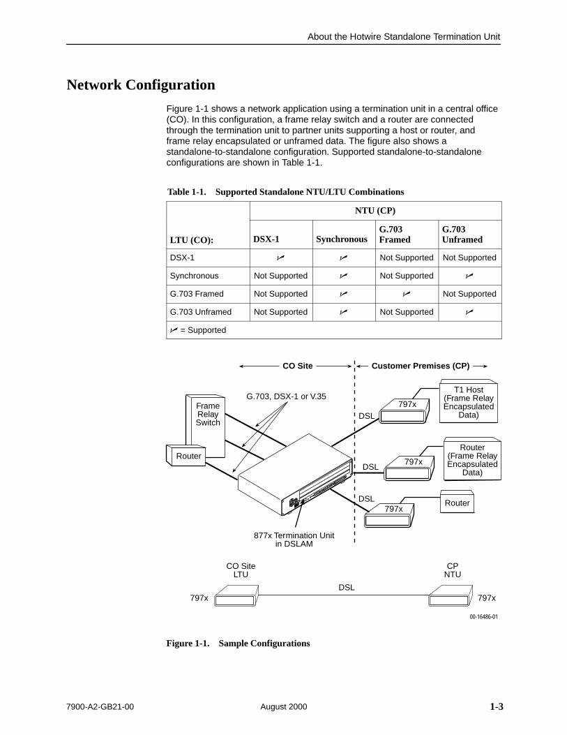
Figure 1-1 shows a network application using a termination unit in a central office(CO). In this configuration, a frame relay switch and a router are connectedthrough the termination unit to partner units supporting a host or router, andframe relay encapsulated or unframed data. The figure also shows astandalone-to-standalone configuration. Supported standalone-to-standaloneconfigurations are shown in Table 1-1.
Table 1-1. Supported Standalone NTU/LTU Combinations
NTU (CP)
LTU (CO): DSX-1 SynchronousG.703Framed
G.703Unframed
DSX-1 Not Supported Not Supported
Synchronous Not Supported Not Supported
G.703 Framed Not Supported Not Supported
G.703 Unframed Not Supported Not Supported
= Supported
FrameRelaySwitch
Router
T1 Host(Frame RelayEncapsulated
Data)
00-16486-01
Router(Frame RelayEncapsulated
Data)
Router
877x Termination Unitin DSLAM
CO Site
797x
797x
797x
797x 797x
CPNTU
CO SiteLTU
DSL
Customer Premises (CP)
DSL
DSL
G.703, DSX-1 or V.35
DSL
Figure 1-1. Sample Configurations
About the Hotwire Standalone Termination Unit
1-4 7900-A2-GB21-00August 2000
Front Panel LED Status Indicators
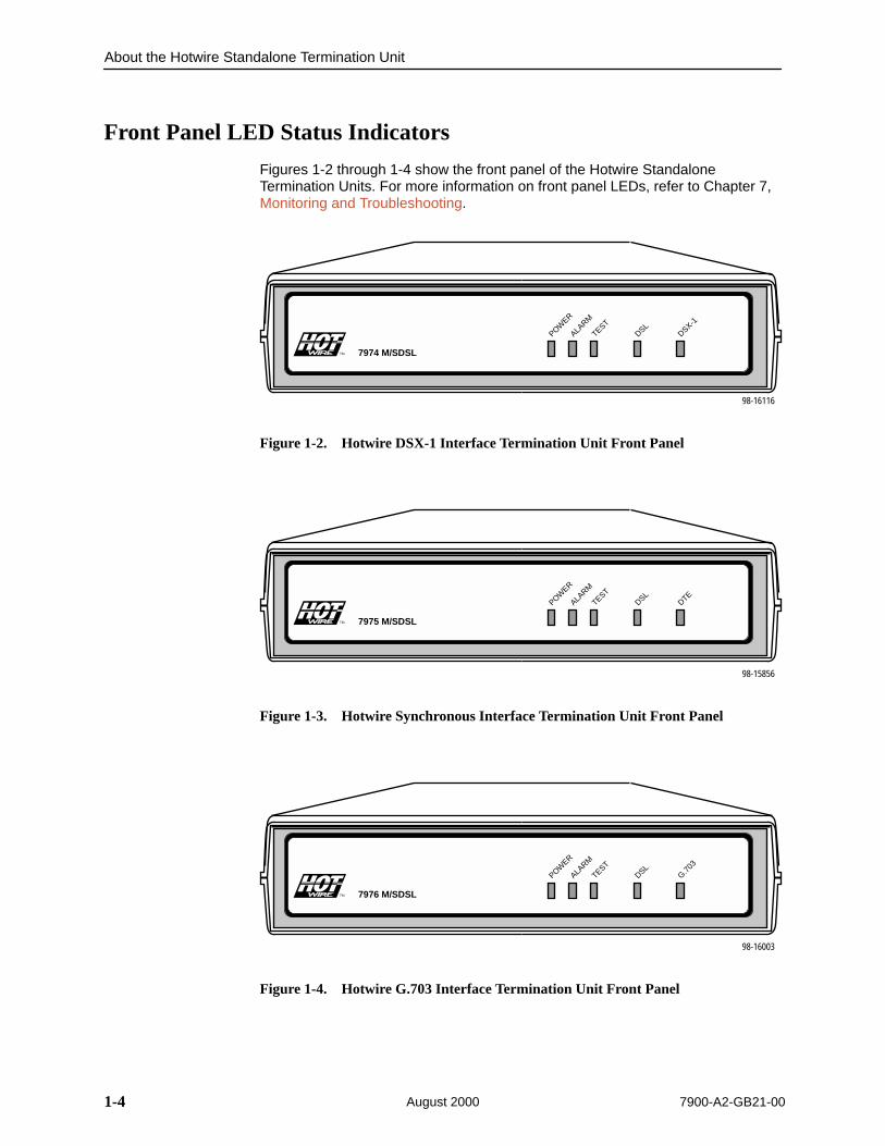
Figures 1-2 through 1-4 show the front panel of the Hotwire StandaloneTermination Units. For more information on front panel LEDs, refer to Chapter 7,Monitoring and Troubleshooting.
POWER
ALARM
TESTDSL
DSX-1
98-16116
7974 M/SDSL
TM
TM
Figure 1-2. Hotwire DSX-1 Interface Termination Unit Front Panel
POWER
ALARM
TESTDSL
DTE
98-15856
7975 M/SDSL
TM
TM
Figure 1-3. Hotwire Synchronous Interface Termination Unit Front Panel
POWER
ALARM
TESTDSL
G.703
98-16003
7976 M/SDSL
TM
TM
Figure 1-4. Hotwire G.703 Interface Termination Unit Front Panel

About the Hotwire Standalone Termination Unit
1-57900-A2-GB21-00 August 2000
Rear Panel Interface Connections
Figures 1-5 through 1-7 show the physical interfaces of the termination units.
POWER DSLCOM DSX-1
98-16117
O
I
Figure 1-5. Hotwire DSX-1 Interface Termination Unit Rear Panel
POWER DSLCOM
98-15880
PORT
O
I
Figure 1-6. Hotwire Synchronous Interface Termination Unit Rear Panel
POWER DSLCOMTX RX
G.703
75Ω120Ω
98-16005
O
I
Figure 1-7. Hotwire G.703 Interface Termination Unit Rear Panel

About the Hotwire Standalone Termination Unit
1-6 7900-A2-GB21-00August 2000
SNMP Management Capabilities
The Hotwire 797x Standalone Termination Units support SNMP Version 1, andcan be managed by any industry-standard SNMP manager and accessed usingSNMP by external SNMP managers.
Management Information Base (MIB) Support
For a detailed description of the supported MIBs, visit Paradyne’s Web site atwww.paradyne.com. Select Technical Support → MIBs.
The following MIBs are supported:
MIB II (RFC 1213 and RFC 1573) – Defines the general objects for use witha network management protocol in TCP/IP internets and provides generalinformation about the unit. MIB II is backward-compatible with MIB I.
DS1/E1 MIB (RFC 1406) – Models 7974 and 7976. Reports the performancestatus of the DSX-1 or G.703 interface and supports the features found onthe DSX-1 or G.703 Performance Statistics screen.
RS-232-Like MIB (RFC 1659) – Defines objects for managing RS-232-typeinterfaces (e.g., V.35, RS-422, RS-423, etc.) and supports the synchronousdata port on the DSU.
Paradyne Enterprise MIB – Supports configuration, status, statistics, andtests.

About the Hotwire Standalone Termination Unit
1-77900-A2-GB21-00 August 2000
SNMP Trap Support
Hotwire 797x Standalone Termination Units support traps as defined in RFC 1215.
Figure 1-8 illustrates a typical DSL SNMP configuration. Figure 1-9 illustrates anDSL SNMP configuration connected directly to the Communications Port. Referto Chapter 5, IP Addressing and Appendix B, Standards Compliance for SNMPTraps.
00-16487-01
DSLAM
Network
797x
AC
INPUTAC
48VDC CLASS 2 ORLIMITED PWR SOURCE
RTN48V
AA B B
T5A
2
4 6
A B
.
..3
.12
POSITIONSTACK
ALM A
IN
B
DC FUSEST4A, MIN. 48V
5DC PWRFAN
OUT SERIAL MCC 1 3
1
2
3SYSTEM
OK Alrm Test
250VSYSTEM
OK Alrm Test
1 2 3 4
G.703
ALR
M
DSL PORT
LI
NK-UP1 2 3 4
SYSTEMOK Alrm Te
st1 2 3 4
G.703
ALR
M
DSL PORT
LI
NK-UP
SD
SL
87151 2 3 4Router
SNMP NMS
EthernetInterface
DSL
EOC Data
Operation, Maintenanceand Provisioning Center
EthernetLAN
1 2 3 4
G.703
ALR
M
DSL PORT
LI
NK-UP1 2 3 4
877x
Figure 1-8. DSL SNMP Configuration
00-16488-01
797x
SNMP NMS
DSL
EOCRouter
Router
797xCOM
Figure 1-9. DSL Local SNMP Configuration

About the Hotwire Standalone Termination Unit
1-8 7900-A2-GB21-00August 2000
This page intentionally left blank.
2-17900-A2-GB21-00 August 2000
Using the Asynchronous TerminalInterface
2User Interface Access
You can communicate with the Hotwire Standalone Termination Unit with anasynchronous terminal interface (ATI) using one of the following methods:
Direct connection through the COM port of the standalone unit or through theserial port of the DSLAM management card.
Telnet session through the Embedded Operations Channel (EOC).
NOTE:Only one terminal interface session can be active at a time, and anotheruser’s session cannot be forced to end. To automatically log out a user due toinactivity, enable the Inactivity Timeout option (see Table A-9, Telnet SessionOptions, in Appendix A, Configuration Options).
Security can limit ATI access several ways. To limit user access or set up loginIDs, refer to Chapter 6, Security.
Communication Port Settings
Ensure that the device you connect communicates using these settings:
Data rate set to 9.6 kbps.
Character length set to 8.
Parity set to None.
Stop Bits set to 1.
Using the Asynchronous Terminal Interface
2-2 7900-A2-GB21-00August 2000
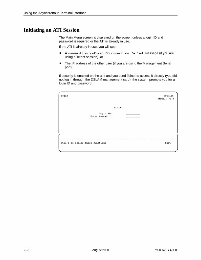
Initiating an ATI SessionThe Main Menu screen is displayed on the screen unless a login ID andpassword is required or the ATI is already in use.
If the ATI is already in use, you will see:
A connection refused or connection failed message (if you areusing a Telnet session), or
The IP address of the other user (if you are using the Management Serialport).
If security is enabled on the unit and you used Telnet to access it directly (you didnot log in through the DSLAM management card), the system prompts you for alogin ID and password.
Î ÎÎ
Login Hotwire Model: 797x
LOGIN
Login ID: Enter Password:
––––––––––––––––––––––––––––––––––––––––––––––––––––––––––––––––––––––––––––––––Ctrl-a to access these functions Exit

Using the Asynchronous Terminal Interface
2-37900-A2-GB21-00 August 2000
After you enter a valid login ID and password, the Main Menu appears. If youenter an invalid login ID and password after three attempts, the Telnet sessioncloses or the terminal connection returns to an idle state. Refer to Chapter 6,Security.
ÎÎÎÎÎÎÎÎÎÎÎÎÎÎÎÎÎÎÎÎÎÎÎÎÎÎÎÎÎÎÎÎÎÎÎÎÎÎÎÎÎÎÎÎÎÎÎÎÎÎÎÎÎÎÎÎÎÎÎÎÎÎÎÎÎÎÎÎÎÎÎÎÎÎÎÎÎÎÎÎÎÎÎÎÎÎÎÎÎÎÎÎÎÎÎÎÎÎÎÎÎÎÎÎÎÎÎÎÎÎÎÎÎÎÎÎÎÎÎÎÎÎÎÎÎÎÎÎÎÎÎÎÎÎÎÎÎÎÎÎÎÎÎÎÎÎÎÎÎÎÎÎÎÎÎÎÎÎÎÎÎÎÎÎÎÎÎÎÎÎÎÎÎÎÎÎÎÎÎÎÎÎÎÎÎÎÎÎÎÎÎÎÎÎÎÎÎÎÎÎÎÎÎÎÎÎÎÎÎÎÎÎÎÎÎÎÎÎÎÎÎÎÎÎÎÎÎÎÎÎÎÎÎÎÎÎÎÎÎÎÎÎÎÎÎÎÎÎÎÎÎÎÎÎÎÎÎÎÎÎÎÎÎÎÎÎÎÎÎÎÎÎÎÎÎÎÎÎÎÎÎÎÎÎÎÎÎÎÎÎÎÎÎÎÎÎÎÎÎÎÎÎÎÎÎÎÎÎÎÎÎÎÎÎÎÎÎÎÎÎÎÎÎÎÎÎÎÎÎÎÎÎÎÎÎÎÎÎÎÎÎÎÎÎÎÎÎÎÎÎÎÎÎÎÎÎÎÎÎÎÎÎÎÎÎÎÎÎÎÎÎÎÎÎÎÎÎÎÎÎÎÎÎÎÎÎÎÎÎÎÎÎÎÎÎÎÎÎÎÎ
main Access Level: Administrator Hotwire Model 797x
MAIN MENU
StatusTestConfigurationControl
––––––––––––––––––––––––––––––––––––––––––––––––––––––––––––––––––––––––––––––––Ctrl-a to access these functions Exit
ScreenArea
ScreenFunctionKeysArea
Entry to all of the Hotwire 797x Standalone Termination Unit’s tasks begins at theMain Menu screen. The four branches of the Main Menu are as follows:
Select . . . To . . .
Status View system status, diagnostic test results, statistics, LEDs, and deviceidentity information.
Test Select and cancel tests for the termination unit’s interfaces.
Configuration Display and edit the configuration options.
Control Change the device identity, administer logins, download new firmware, orinitiate a power-on reset of the termination unit.
After selecting an option, what appears on the screens depends on the:
Current configuration – How your unit is currently configured.
Effective security access level – An access level that is typically set by thesystem administrator for each interface and each user.
Data selection criteria – What you entered in previous screens.

Using the Asynchronous Terminal Interface
2-4 7900-A2-GB21-00August 2000
Menu Tree
The following illustration shows the menu paths to the different ATI screens.
Main
Status Test
System andTest Status
PerformanceStatistics
DisplayLEDs
Identity
NetworkError
StatisticsNetwork
PerformanceStatistics
Configuration Control
FactoryConfig
ConfigurationLoader
Current ConfigurationEdit/Display
SystemOptions
CommunicationPort
Managementand
Communication
ChangeIdentity
AdministerLogins
DownloadCode
ApplyDownload
ResetAutoRate
DeviceTests
AbortAll
Tests
00-16496-02
ResetDevice
Network
General SNMPManagement
SNMP NMSSecurity
CommunicationProtocol
TelnetSession
SNMPTraps
7974: DSX-1 Statistics7975: (Not Applicable)7976: G.703 Statistics
7974: Network and DSX-1 Tests7975: Network Tests7976: Network and G.703 Tests
7974: (Not Applicable)7975: Sync Data Port Tests7976: (Not Applicable)
7974: DSX-17975: Sync Ports7976: G.703

Using the Asynchronous Terminal Interface
2-57900-A2-GB21-00 August 2000
Screen Work Areas
There are two user work areas:
Screen area – This is the area above the dotted line that provides the menupath, menus, and input fields.
The menu path appears as the first line on the screen. In this manual, themenu path is presented as a menu selection sequence with the names of thescreens:
Main Menu →Configuration → Load Configuration From →NetworkInterface Options
Screen function key area – This is the area below the dotted line that listsfunction keys specific to the screen, field value choices, and systemmessages.
ÎÎÎÎÎÎÎÎÎÎÎÎÎÎÎÎÎÎÎÎÎÎÎÎÎÎÎÎÎÎÎÎÎÎÎÎÎÎÎÎÎÎÎÎÎÎÎÎÎÎÎÎÎÎÎÎÎÎÎÎÎÎÎÎÎÎÎÎÎÎÎÎÎÎÎÎÎÎÎÎÎÎÎÎÎÎÎÎÎÎÎÎÎÎÎÎÎÎÎÎÎÎÎÎÎÎÎÎÎÎÎÎÎÎÎÎÎÎÎÎÎÎÎÎÎÎÎÎÎÎÎÎÎÎÎÎÎÎÎÎÎÎÎÎÎÎÎÎÎÎÎÎÎÎÎÎÎÎÎÎÎÎÎÎÎÎÎÎÎÎÎÎÎÎÎÎÎÎÎÎÎÎÎÎÎÎÎÎÎÎÎÎÎÎÎÎÎÎÎÎÎÎÎÎÎÎÎÎÎÎÎÎÎÎÎÎÎÎÎÎÎÎÎÎÎÎÎÎÎÎÎÎÎÎÎÎÎÎÎÎÎÎÎÎÎÎÎÎÎÎÎÎÎÎÎÎÎÎÎÎÎÎÎÎÎÎÎÎÎÎÎÎÎÎÎÎÎÎÎÎÎÎÎÎÎÎÎÎÎÎÎÎÎÎÎÎÎÎÎÎÎÎÎÎÎÎÎÎÎÎÎÎÎÎÎÎÎÎÎÎÎÎÎÎÎÎÎÎÎÎÎÎÎÎÎÎÎÎÎÎÎÎÎÎÎÎÎÎÎÎÎÎÎÎÎÎÎÎÎÎÎÎÎÎÎÎÎÎÎÎÎÎÎÎÎÎÎÎÎÎÎÎÎÎÎÎÎÎÎÎÎÎÎÎÎÎÎÎÎÎ
Menu Path
ScreenFunction
Keys
Field ValueChoices
SystemMessages
Input Fields
main/config/network Hotwire Model: 797x
NETWORK INTERFACE OPTIONS
Margin Threshold: –3dbExcessive Error Rate Threshold: 1E–5AutoRate: DisableDSL Line Rate: 1552 kbpsEIA-530 Payload Rate 1536 kbpsTransmit Attenuation 0dBPeer IP Address: 111.255.255.000 Clear
Circuit Identifier: Clear
––––––––––––––––––––––––––––––––––––––––––––––––––––––––––––––––––––––––––––––––Ctrl-a to access these functions, ESC for previous menu MainMenu Exit SaveSelect: 1E–4, 1E–5, 1E–6, 1E–7, 1E–8, 1E–9 LOS at Net, Pt 1

Using the Asynchronous Terminal Interface
2-6 7900-A2-GB21-00August 2000
Navigating the Screens
You can navigate the screens by:
Using keyboard keys
Using screen function keys
Switching between the two screen work areas
Keyboard Keys
Use the following keyboard keys to navigate within the screen.
Press . . . To . . .
Backspace Move cursor to the previous field on the screen.
Ctrl-a Move cursor between the screen area and the screen functionkeys area below the dotted line at the bottom of the screen.
Ctrl-k Tab backwards (move cursor one field to the left).
Ctrl-l Redraw the screen display, clearing information typed in but notyet entered.
Delete (Del) Delete character that the cursor is on.
Down Arrow or Ctrl-d Move cursor down one field within a column on the same screen.
Esc Return to the previous screen.
Left Arrow or Ctrl-b Move cursor one character to the left if in edit mode.
Return (Enter) Accept entry or display valid options on the last row of the screenwhen pressed before entering data or after entering invalid data.
Right Arrow or Ctrl-f Move cursor one character to the right if in edit mode.
Spacebar Select the next valid value for the field.
Tab Move cursor to the next field on the screen.
Up Arrow or Ctrl-u Move cursor up one field within a column on the same screen.
Using the Asynchronous Terminal Interface
2-77900-A2-GB21-00 August 2000
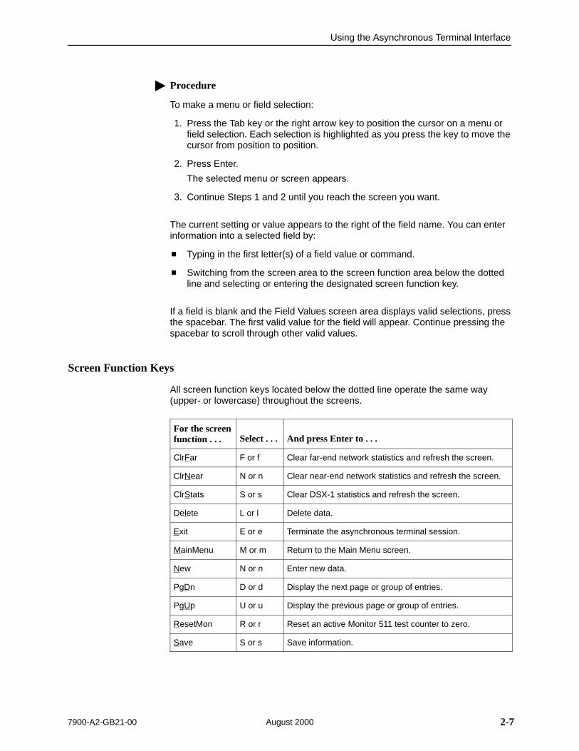
Procedure
To make a menu or field selection:
1. Press the Tab key or the right arrow key to position the cursor on a menu orfield selection. Each selection is highlighted as you press the key to move thecursor from position to position.
2. Press Enter.
The selected menu or screen appears.
3. Continue Steps 1 and 2 until you reach the screen you want.
The current setting or value appears to the right of the field name. You can enterinformation into a selected field by:
Typing in the first letter(s) of a field value or command.
Switching from the screen area to the screen function area below the dottedline and selecting or entering the designated screen function key.
If a field is blank and the Field Values screen area displays valid selections, pressthe spacebar. The first valid value for the field will appear. Continue pressing thespacebar to scroll through other valid values.
Screen Function Keys
All screen function keys located below the dotted line operate the same way(upper- or lowercase) throughout the screens.
For the screenfunction . . . Select . . . And press Enter to . . .
ClrFar F or f Clear far-end network statistics and refresh the screen.
ClrNear N or n Clear near-end network statistics and refresh the screen.
ClrStats S or s Clear DSX-1 statistics and refresh the screen.
Delete L or l Delete data.
Exit E or e Terminate the asynchronous terminal session.
MainMenu M or m Return to the Main Menu screen.
New N or n Enter new data.
PgDn D or d Display the next page or group of entries.
PgUp U or u Display the previous page or group of entries.
ResetMon R or r Reset an active Monitor 511 test counter to zero.
Save S or s Save information.
Using the Asynchronous Terminal Interface
2-8 7900-A2-GB21-00August 2000
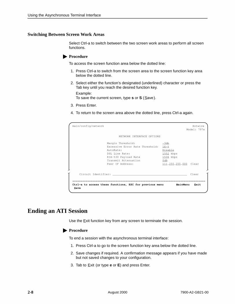
Switching Between Screen Work Areas
Select Ctrl-a to switch between the two screen work areas to perform all screenfunctions.
Procedure
To access the screen function area below the dotted line:
1. Press Ctrl-a to switch from the screen area to the screen function key areabelow the dotted line.
2. Select either the function’s designated (underlined) character or press theTab key until you reach the desired function key.
Example:To save the current screen, type s or S (Save).
3. Press Enter.
4. To return to the screen area above the dotted line, press Ctrl-a again.
ÎÎ
ÎÎÎÎ
main/config/network Hotwire Model: 797x
NETWORK INTERFACE OPTIONS
Margin Threshold: –3dbExcessive Error Rate Threshold: 1E–5AutoRate: DisableDSL Line Rate: 1552 kbpsEIA-530 Payload Rate 1536 kbpsTransmit Attenuation 0dBPeer IP Address: 111.255.255.000 Clear
Circuit Identifier: Clear
––––––––––––––––––––––––––––––––––––––––––––––––––––––––––––––––––––––––––––––––Ctrl-a to access these functions, ESC for previous menu MainMenu Exit Save
Ending an ATI Session
Use the Exit function key from any screen to terminate the session.
Procedure
To end a session with the asynchronous terminal interface:
1. Press Ctrl-a to go to the screen function key area below the dotted line.
2. Save changes if required. A confirmation message appears if you have madebut not saved changes to your configuration.
3. Tab to Exit (or type e or E) and press Enter.
3-17900-A2-GB21-00 August 2000
Initial Startup and Configuration
3Overview
This chapter provides instructions on how to access and configure your Hotwire 797x Standalone Termination Unit for the first time. This chapter includesprocedures for:
Connecting power to the unit.
Connecting the unit to the network.
Connecting the unit to a DTE.
Connecting the unit to a system terminal.
Providing initial unit identity information or changing existing identityinformation.
Configuring your unit using the Configuration Edit menus or internal switches.
Choosing the current or factory default configuration options.
Modifying current configuration options using the Configuration Edit/Displaymenu.
Downloading configuration options from a TFTP server.
Saving your configuration options.
Downloading unit firmware from a TFTP server.
This chapter also explains how to disable and reset AutoRate.

99-16291
23
5 46
1
Initial Startup and Configuration
3-2 7900-A2-GB21-00August 2000
Connecting Power
If your package includes a power pack: Plug the power pack into an AC outlethaving a nominal voltage rating between 100–240 VAC. Connect the output cableof the power pack to the connector marked POWER on the rear panel.
If your package includes a direct-connection DC power cable: Connect theunit to an external +24 or –48 VDC power source as described in Connecting theUnit to an Optional External DC Power Source.
Connecting to an Optional External DC Power Source
Using the DC power cable, the Hotwire 797x Standalone Termination Unit iscapable of operating on a +24 or –48 VDC power supply.
Procedure
To use the DC power cable with +24 VDC:
1. Connect the green wire to a suitable ground.
2. Connect the orange wire to the +24 VDC source.
3. Connect the white wire to the return.
4. Cut the black, red, and blue wires off at the outer insulation.
5. Plug the power connector into the Power receptacle of the unit.
Procedure
To use the DC power cable with –48 VDC:
1. Connect the green wire to a suitable ground.
2. Connect the orange wire to the –48 VDC source.
3. Connect the black wire to the return.
4. Cut the red, white, and blue wires off at the outer insulation.
5. Plug the power connector into the Power receptacle of the unit.
Power Input Connector
Pin Number Wire Color Signal
1 Black –48 VDC Return
2 Red –48 VDC Return
3 Green Ground
4 White +24 VDC Return
5 Orange –48 VDC
+24 VDC
6 Blue No Connection
Initial Startup and Configuration
3-37900-A2-GB21-00 August 2000
Connecting to the Network
Procedure
To connect your unit to the network:
1. Connect one end of the network cable into the rear panel DSL jack.
2. Connect the other end to your DSL network interface.
NOTE:Do not use a flat VF network cable as this may severely degrade theperformance of the unit. Use only Cat 5 twisted-pair network cable.
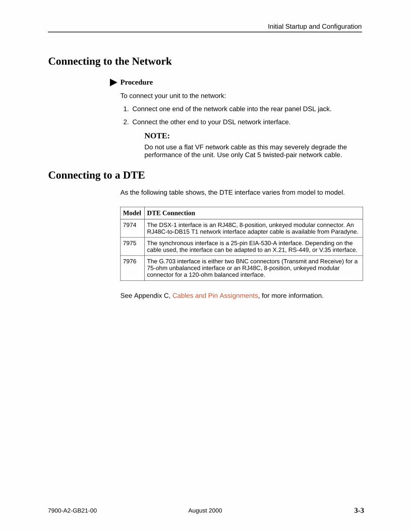
Connecting to a DTE
As the following table shows, the DTE interface varies from model to model.
Model DTE Connection
7974 The DSX-1 interface is an RJ48C, 8-position, unkeyed modular connector. AnRJ48C-to-DB15 T1 network interface adapter cable is available from Paradyne.
7975 The synchronous interface is a 25-pin EIA-530-A interface. Depending on thecable used, the interface can be adapted to an X.21, RS-449, or V.35 interface.
7976 The G.703 interface is either two BNC connectors (Transmit and Receive) for a75-ohm unbalanced interface or an RJ48C, 8-position, unkeyed modularconnector for a 120-ohm balanced interface.
See Appendix C, Cables and Pin Assignments, for more information.
Initial Startup and Configuration
3-4 7900-A2-GB21-00August 2000
Connecting to a System Terminal
An optional system maintenance terminal may be attached to your Hotwire 797xStandalone Termination Unit through the modular jack on the rear panel. Thesystem maintenance terminal allows you to view the status of the unit and changeconfiguration options. The terminal must be a VT100-compatible terminal or a PCrunning terminal emulation software.
Procedure
To connect your unit to a system terminal:
1. Connect the 9-pin end of the terminal cable into a COM port on your PC.
2. Plug the other end into the modular jack on the rear panel.
— If your PC requires a 25-pin connector to the COM port, see Appendix C,Cables and Pin Assignments, for the correct cable pinouts.
3. Set the communication parameters on your PC or terminal to:
— 9600 baud
— 8 bit characters
— no parity
— 1 stop bit
— no flow control

Initial Startup and Configuration
3-57900-A2-GB21-00 August 2000
Entering Identity Information
After accessing your unit for the first time, use the Change Identity screen todetermine SNMP administrative system information that will be displayed on theIdentity screen of the Status branch. To access the Identity screen, follow thismenu selection sequence:
Main Menu →Control →Change Identity
ÎÎ
ÎÎÎÎ
main/control/change_identity Model: 797x
IDENTITY
System Name: Fess lllQJ98-001 ClearSystem Location: Bldg. A412, 2nd Floor, Left cabinet ClearSystem Contact: R. Byrd 800-727-2396 pager 888-555-1212 Clear
––––––––––––––––––––––––––––––––––––––––––––––––––––––––––––––––––––––––––––––––Ctrl-a to access these functions, ESC for previous menu MainMenu Exit Save
The three System entry fields are alphanumeric and provide 128 characters foreach field. The System entries appear on the Identity display as shown above.The SNMP System entry fields are:
System Name: The general SNMP system name.
System Location: The physical location of the SNMP-managed device.
System Contact: Identification information, such as contact name, phonenumber, or mailing address.
Valid entry values are any printable ASCII character. ASCII printable charactersinclude:
Numeric 0–9
Upper- or lowercase A–Z
Space
All ASCII symbols except the caret (^)
Select Clear to reset a field to a null value.

Initial Startup and Configuration
3-6 7900-A2-GB21-00August 2000
Procedure
To enter Change Identity screen information:
1. Position the cursor in the System Name field. Enter a name unique in yournetwork to identify the SNMP managed node (or unit).
The maximum length of System Name is 128 characters.
2. Position the cursor in the System Location field. Enter the physical location ofthe unit.
The maximum length of System Location is 128 characters.
3. Position the cursor in the System Contact field. Enter the name and contactinformation for the person responsible for the unit.
The maximum length of System Contact is 128 characters.
4. Press Ctrl-a to switch to the screen function key area below the dotted line.
5. Select Save and press Enter.
Select Clear to reset a field to a null value.

Initial Startup and Configuration
3-77900-A2-GB21-00 August 2000
Choosing a Configuration MethodYou can make configuration changes either through a VT100-compatible terminaland the unit’s Configuration menus or by manually changing switches on theboard. The unit is shipped with the switchpacks disabled to allow settings to bemade through the Configuration menus. To use the switches, see Chapter 4,Configuring the Unit Using the Internal Switches.
Configuring the Unit Using the Configuration Menus
Use the Configuration menus to select, display, or change configuration optionsettings.
NOTE:The Hotwire 797x Standalone Termination Unit is preconfigured as an NTU. Ifyou are using this unit as an NTU, the configuration options may not need tobe changed.
The Hotwire 797x Standalone Termination Unit is shipped with factory settings inthe Default Factory configuration area. You can find default information by:
Referring to Appendix A, Configuration Options.
Accessing the Configuration branch of the Hotwire 797x StandaloneTermination Unit menu.
The Hotwire 797x Standalone Termination Unit has two sets of configurationoption settings. The Current Configuration matches the Default FactoryConfiguration until modified and saved by the user.
Configuration Option Area Configuration Option Set
Current Configuration The unit’s active set of configuration options.
Default Factory Configuration A read-only configuration area containing the factorydefault configuration options.
If the factory default settings do not support your network’s configuration, you cancustomize the configuration options for your application.
Initial Startup and Configuration
3-8 7900-A2-GB21-00August 2000
Accessing and Displaying Configuration Options
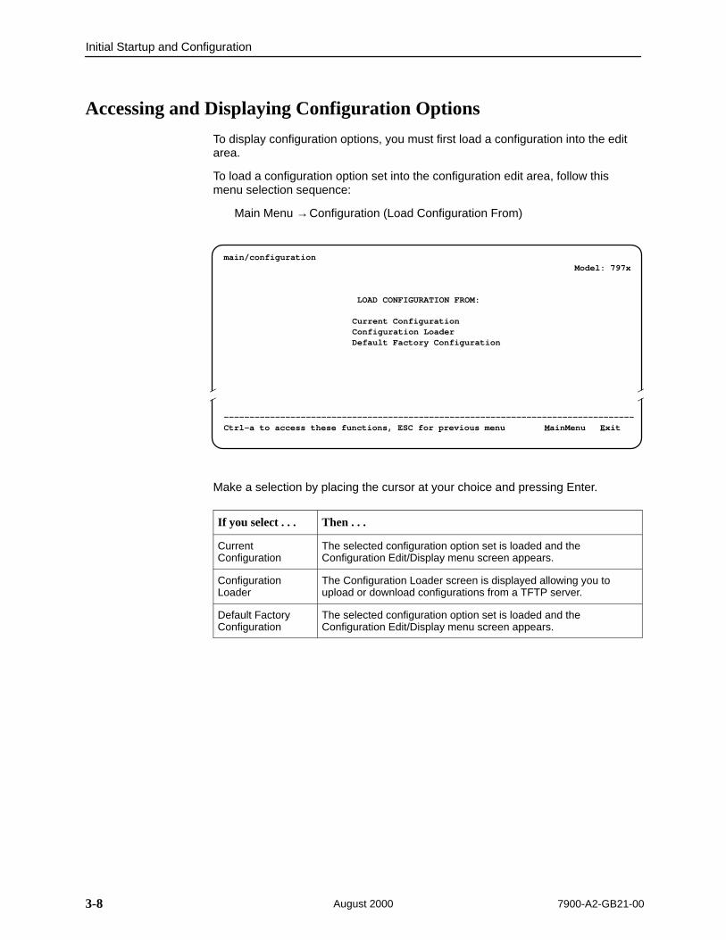
To display configuration options, you must first load a configuration into the editarea.
To load a configuration option set into the configuration edit area, follow thismenu selection sequence:
Main Menu →Configuration (Load Configuration From)
main/configuration Model: 797x
LOAD CONFIGURATION FROM:
Current ConfigurationConfiguration LoaderDefault Factory Configuration
––––––––––––––––––––––––––––––––––––––––––––––––––––––––––––––––––––––––––––––––Ctrl-a to access these functions, ESC for previous menu MainMenu Exit
Î ÎÎ
Make a selection by placing the cursor at your choice and pressing Enter.
If you select . . . Then . . .
CurrentConfiguration
The selected configuration option set is loaded and theConfiguration Edit/Display menu screen appears.
ConfigurationLoader
The Configuration Loader screen is displayed allowing you toupload or download configurations from a TFTP server.
Default FactoryConfiguration
The selected configuration option set is loaded and theConfiguration Edit/Display menu screen appears.

Initial Startup and Configuration
3-97900-A2-GB21-00 August 2000
Configuration Edit/Display
The Configuration Edit/Display screen appears when the current or defaultconfiguration is loaded. To access the Configuration Edit/Display screen, followthis menu selection sequence:
Main Menu →Configuration →Current Configuration
– or –
Main Menu →Configuration →Default Factory Configuration
ÎÎ
ÎÎÎÎ
main/config/edit Model: 797x
CONFIGURATION EDIT/DISPLAY
NetworkDSX-1 | SYNC Port | G.703System OptionsCommunication PortManagement and Communication
–––––––––––––––––––––––––––––––––––––––––––––––––––––––––––––––––––––––––––––––Ctrl-a to access these functions, ESC for previous menu MainMenu Exit Save
Initial Startup and Configuration
3-10 7900-A2-GB21-00August 2000
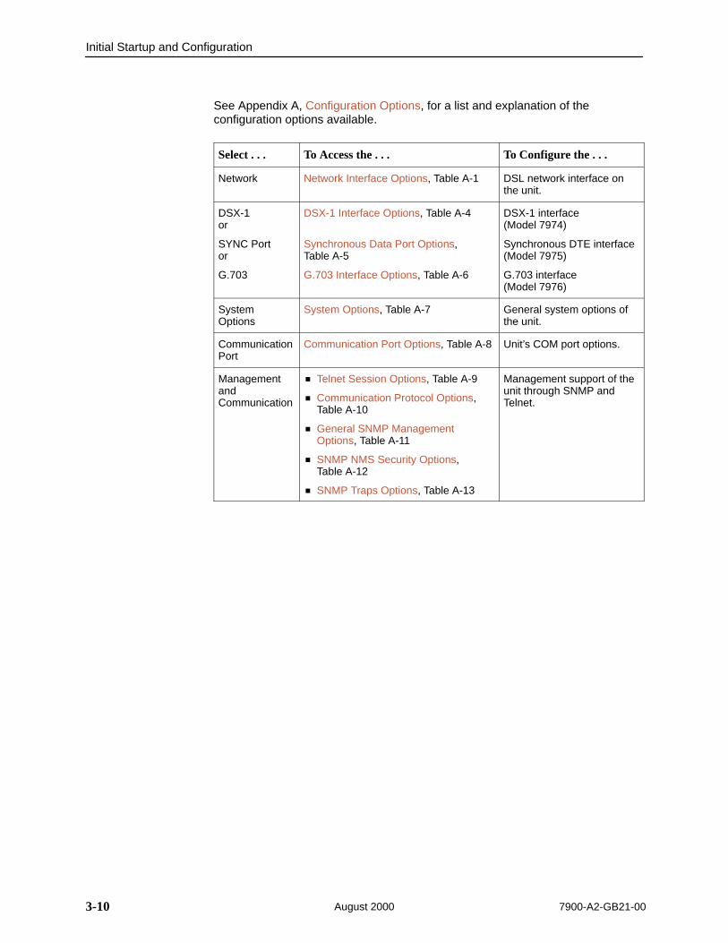
See Appendix A, Configuration Options, for a list and explanation of theconfiguration options available.
Select . . . To Access the . . . To Configure the . . .
Network Network Interface Options, Table A-1 DSL network interface onthe unit.
DSX-1or
SYNC Portor
G.703
DSX-1 Interface Options, Table A-4
Synchronous Data Port Options, Table A-5
G.703 Interface Options, Table A-6
DSX-1 interface (Model 7974)
Synchronous DTE interface(Model 7975)
G.703 interface (Model 7976)
SystemOptions
System Options, Table A-7 General system options ofthe unit.
CommunicationPort
Communication Port Options, Table A-8 Unit’s COM port options.
ManagementandCommunication
Telnet Session Options, Table A-9
Communication Protocol Options, Table A-10
General SNMP ManagementOptions, Table A-11
SNMP NMS Security Options, Table A-12
SNMP Traps Options, Table A-13
Management support of theunit through SNMP andTelnet.

Initial Startup and Configuration
3-117900-A2-GB21-00 August 2000
Configuration Loader
The Configuration Loader screen allows you to upload configurations to anddownload configurations from a TFTP server. To access the Configuration Loaderscreen, follow this menu selection sequence:
Main Menu →Configuration →Configuration Loader
ÎÎÎÎÎÎÎÎÎÎÎÎÎÎÎÎÎÎÎÎÎÎÎÎÎÎÎÎÎÎÎÎÎÎÎÎÎÎÎÎÎÎÎÎÎÎÎÎÎÎÎÎÎÎÎÎÎÎÎÎÎÎÎÎÎÎÎÎÎÎÎÎÎÎÎÎÎÎÎÎÎÎÎÎÎÎÎÎÎÎÎÎÎÎÎÎÎÎÎÎÎÎÎÎÎÎÎÎÎÎÎÎÎÎÎÎÎÎÎÎÎÎÎÎÎÎÎÎÎÎÎÎÎÎÎÎÎÎÎÎÎÎÎÎÎÎÎÎÎÎÎÎÎÎÎÎÎÎÎÎÎÎÎÎÎÎÎÎÎÎÎÎÎÎÎÎÎÎÎÎÎÎÎÎÎÎÎÎÎÎÎÎÎÎÎÎÎÎÎÎÎÎÎÎÎÎÎÎÎÎÎÎÎÎÎÎÎÎÎÎÎÎÎÎÎÎÎÎÎÎÎÎÎÎÎÎÎÎÎÎÎÎÎÎÎÎÎÎÎÎÎÎÎÎÎÎÎÎÎÎÎÎÎÎÎÎÎÎÎÎÎÎÎÎÎÎÎÎÎÎÎÎÎÎÎÎÎÎÎÎÎÎÎÎÎÎÎÎÎÎÎÎÎÎÎÎÎÎÎÎÎÎÎÎÎÎÎÎÎÎÎÎÎÎÎÎÎÎÎÎÎÎÎÎÎÎÎÎÎÎÎÎÎÎÎÎÎÎÎÎÎÎÎÎÎÎÎÎÎÎÎÎÎÎÎÎÎÎÎÎÎÎÎÎÎ
main/configuration/config_loader Model: 797x
CONFIGURATION LOADER
Configuration File Name: Clear TFTP Server IP Address: 000.000.000.000 ClearTFTP Transfer Direction: Download from Server
Destination: DSL
Start Transfer: Yes
Packets Sent: 0000000 Packets Received: 0000000 Bytes Sent: 0000000 Bytes Received: 0000000 Transfer Status: Transfer Pending
Activate new configuration? No
–––––––––––––––––––––––––––––––––––––––––––––––––––––––––––––––––––––––––––––––Ctrl-a to access these functions, ESC for previous menu MainMenu Exit

Initial Startup and Configuration
3-12 7900-A2-GB21-00August 2000
Procedure
To upload or download a configuration:
1. Position the cursor in the Image File Name field. Type the name of the file tobe downloaded, or the name to be used for the file to be uploaded.
The filename may be a regular path name expression of directory namesseparated by a forward slash (/ ) ending with the filename. The total pathname length can be up to 128 characters.
— DOS machine: If the TFTP server is hosted by a DOS machine, thendirectory and filenames must consist of eight or less characters with anoptional suffix of up to three characters. The system will automaticallyupload the configuration file and create directories and filenames asneeded.
— UNIX machine: If your server is hosted by a UNIX machine, theconfiguration file you name must already exist. It will not be created onthe UNIX system by the TFTP server. It is critical that you work with yoursystem administrator to plan the naming conventions for directories,filenames, and permissions so that anyone using the system has readand write permissions.
2. Position the cursor in the TFTP Server IP Address field. Enter the TFTPserver IP address.
3. Position the cursor in the Destination field. Use the spacebar to select anetwork destination for the TFTP server. Select DSL if the TFTP serverdestination is the DSL link or COM if the TFTP destination is the COM port.
4. Position the cursor in the TFTP Transfer Direction field. Use the spacebar toselect Download from Server or Upload to Server.
5. Position the cursor at the Start Transfer field. Use the spacebar to select Yes.Press Enter.
When the data transfer is complete, the Transfer Status field changes toCompleted successfully.
6. Position the cursor at the Activate new configuration? prompt andselect Yes to activate a new downloaded configuration. Press Enter.
NOTE:The configuration options DSL Mode and Telnet Session are not changedwhen a new configuration is loaded. You must change these settings with theappropriate configuration menus after the new configuration is activated. SeeTable A-7, System Options, and Table A-9, Telnet Session Options, inAppendix A, Configuration Options.

Initial Startup and Configuration
3-137900-A2-GB21-00 August 2000
Saving Configuration Options
When changes are made to the configuration options through the ConfigurationEdit/Display branch, the changes must be saved to take effect. Use the Save keyor Save Configuration screen.
Procedure
To save configuration options changes:
1. Press Ctrl-a to switch to the screen function key area below the dotted line.
2. Select Save and press Enter.
NOTE:When Exit is selected before Save, or Save has been selected from anymenu in the Configuration/Edit branch, a Save Configuration screen appearsrequiring a Yes or No response.
ÎÎ
ÎÎÎÎ
main/config/saveprompt Model: 797x
SAVE CONFIGURATION
Save Changes? No
–––––––––––––––––––––––––––––––––––––––––––––––––––––––––––––––––––––––––––––––Ctrl-a to access these functions, ESC for previous menu MainMenu Exit
Command Complete
If you select . . . Then . . .
Yes The configuration is saved.
No The Main Menu appears and changes are not saved.
If the Telnet Session configuration option is changed, a message appears on theSave Configuration screen warning that an answer of Yes will cause the Telnetsession to disconnect. Do not answer Yes unless you are prepared to disconnect.
If the DSL Mode configuration option is changed, a message is appears on theSave Configuration screen warning that an answer of Yes will cause the systemto be reset. Do not answer Yes unless you are prepared to reset the unit.

Initial Startup and Configuration
3-14 7900-A2-GB21-00August 2000
Downloading Code
The Download Code screen allows you to download firmware from a TFTPserver. To access the Download Code screen, follow this menu selectionsequence:
Main Menu →Control →Download Code
ÎÎÎÎÎÎÎÎÎÎÎÎÎÎÎÎÎÎÎÎÎÎÎÎÎÎÎÎÎÎÎÎÎÎÎÎÎÎÎÎÎÎÎÎÎÎÎÎÎÎÎÎÎÎÎÎÎÎÎÎÎÎÎÎÎÎÎÎÎÎÎÎÎÎÎÎÎÎÎÎÎÎÎÎÎÎÎÎÎÎÎÎÎÎÎÎÎÎÎÎÎÎÎÎÎÎÎÎÎÎÎÎÎÎÎÎÎÎÎÎÎÎÎÎÎÎÎÎÎÎÎÎÎÎÎÎÎÎÎÎÎÎÎÎÎÎÎÎÎÎÎÎÎÎÎÎÎÎÎÎÎÎÎÎÎÎÎÎÎÎÎÎÎÎÎÎÎÎÎÎÎÎÎÎÎÎÎÎÎÎÎÎÎÎÎÎÎÎÎÎÎÎÎÎÎÎÎÎÎÎÎÎÎÎÎÎÎÎÎÎÎÎÎÎÎÎÎÎÎÎÎÎÎÎÎÎÎÎÎÎÎÎÎÎÎÎÎÎÎÎÎÎÎÎÎÎÎÎÎÎÎÎÎÎÎÎÎÎÎÎÎÎÎÎÎÎÎÎÎÎÎÎÎÎÎÎÎÎÎÎÎÎÎÎÎÎÎÎÎÎÎÎÎÎÎÎÎÎÎÎÎÎÎÎÎÎÎÎÎÎÎÎÎÎÎÎÎÎÎÎÎÎÎÎÎÎÎÎÎÎÎÎÎÎÎÎÎÎÎÎÎÎÎÎÎÎÎÎÎÎÎÎÎÎÎÎÎÎÎÎÎÎÎÎÎÎÎÎÎÎÎÎÎÎÎÎÎÎÎÎÎÎÎÎÎÎÎÎÎÎ
main/control/download_code Model: 797x
DOWNLOAD CODE
Image File Name: Clear TFTP Server IP Address: 000.000.000.000 Clear
Destination: DSL Immediately Apply Download: Yes Start Transfer: No
Packets Sent: 0000000 Packets Received: 0000000 Bytes Sent: 0000000 Bytes Received: 0000000 Transfer Status: Transfer Pending
–––––––––––––––––––––––––––––––––––––––––––––––––––––––––––––––––––––––––––––––Ctrl-a to access these functions, ESC for previous menu MainMenu Exit

Initial Startup and Configuration
3-157900-A2-GB21-00 August 2000
Procedure
To download firmware:
1. Position the cursor in the Image File Name field. Type the name of the file tobe downloaded.
The file name may be a regular path name expression of directory namesseparated by a forward slash (/ ) ending with the file name. The total pathname length can be up to 128 characters.
2. Position the cursor in the TFTP Server IP Address field. Enter the TFTPserver IP address.
3. Position the cursor in the Destination field. Use the spacebar to select anetwork destination for the TFTP server. Select DSL if the TFTP serverdestination is the DSL link or COM if the TFTP destination is the COM port.
4. Position the cursor in the Immediately Apply Download field. If you would likethe download to be effective immediately, select Yes.
5. Position the cursor at the Start Transfer field. Use the spacebar to select Yes.Press Enter.
When the data transfer is complete:
— If you selected Yes in Step 4, the unit is reset.
— If you selected No in Step 4, the Transfer Status field changes toCompleted successfully.
If you specified No (the default) in the Immediately Apply Download field in Step 4above, you must now apply the download.
Procedure
To apply the downloaded firmware:
1. Press the Escape key to return to the Control menu. Select Apply Download.
2. On the Apply Download screen, type Yes to reset the card and activate thecode.
Initial Startup and Configuration
3-16 7900-A2-GB21-00August 2000
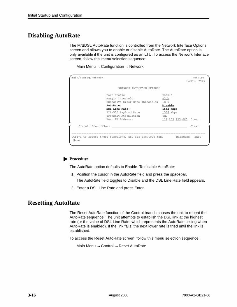
Disabling AutoRate
The M/SDSL AutoRate function is controlled from the Network Interface Optionsscreen and allows you to enable or disable AutoRate. The AutoRate option isonly available if the unit is configured as an LTU. To access the Network Interfacescreen, follow this menu selection sequence:
Main Menu →Configuration →Network
ÎÎ
ÎÎÎÎ
main/config/network Hotwire Model: 797x
NETWORK INTERFACE OPTIONS
Port Status Enable Margin Threshold: –3dbExcessive Error Rate Threshold: 1E–5AutoRate: DisableDSL Line Rate: 1552 kbpsEIA-530 Payload Rate 1536 kbpsTransmit Attenuation 0dBPeer IP Address: 111.255.255.000 Clear
Circuit Identifier: Clear
––––––––––––––––––––––––––––––––––––––––––––––––––––––––––––––––––––––––––––––––Ctrl-a to access these functions, ESC for previous menu MainMenu Exit Save
Procedure
The AutoRate option defaults to Enable. To disable AutoRate:
1. Position the cursor in the AutoRate field and press the spacebar.
The AutoRate field toggles to Disable and the DSL Line Rate field appears.
2. Enter a DSL Line Rate and press Enter.
Resetting AutoRate
The Reset AutoRate function of the Control branch causes the unit to repeat theAutoRate sequence. The unit attempts to establish the DSL link at the highestrate (or the value of DSL Line Rate, which represents the AutoRate ceiling whenAutoRate is enabled). If the link fails, the next lower rate is tried until the link isestablished.
To access the Reset AutoRate screen, follow this menu selection sequence:
Main Menu →Control →Reset AutoRate
4-17900-A2-GB21-00 August 2000
Configuring the Unit Using theInternal Switches
4Overview
You can make configuration changes either through a VT100-compatible terminaland the unit’s Configuration menus or by manually changing switches on theboard. The unit is shipped with the switchpacks disabled to allow settings to bemade through the Configuration menus. To use the Configuration menus, seeChapter 3, Initial Startup and Configuration.
Configuring the Unit Using the Internal Switches
4-2 7900-A2-GB21-00August 2000
Configuring the Unit Using the Internal Switches
Use internal Switchpacks S3 and S4 to manually configure the unit. Use Figure 4-1 to locate Switchpacks S3 and S4.
! HANDLING PRECAUTIONS FORSTATIC-SENSITIVE DEVICESThis product is designed to protect sensitive components fromdamage due to electrostatic discharge (ESD) during normal operation.When performing installation procedures, however, take proper staticcontrol precautions to prevent damage to equipment. If you are notsure of the proper static control precautions, contact your nearestsales or service representative.
Procedure
To configure the unit using internal Switchpacks S3 and S4:
1. Power off the unit.
2. Remove the enclosure cover:
— Use a Phillips screwdriver to remove the two screws from the top of theunit.
— Push a flat-blade screwdriver through the slots on both sides of thehousing to free the four inner latches.
3. Locate Switchpack S4 on the circuit board using Figure 4-1.
4. Set Switch 1 on Switchpack S4 to ON to enable Switchpacks S3 and S4.
5. After you enable the switchpacks, you must set the switches to your desiredconfiguration. Refer to Figure 4-1 and Tables 4-1 through 4-11.
6. Replace the cover and fasten it with the two screws.
7. Power on the board to reset and enable the new configuration.
496-15104

Configuring the Unit Using the Internal Switches
4-37900-A2-GB21-00 August 2000
Switchpack Locations
Use Figure 4-1 to locate Switchpacks S3 and S4.
SwitchpackS3 & S4
6 7 8
ON
1 2 3 4 5
6 7 8
ON
1 2 3 4 5
00-16788
6 7 8
ON
1 2 3 4 5
6 7 8
ON
1 2 3 4 5
S3
S4
Rear
Front
Figure 4-1. Hotwire Standalone Termination Unit Switchpack Locations
Configuring the Unit Using the Internal Switches
4-4 7900-A2-GB21-00August 2000
Switchpack Definitions for Model 7974
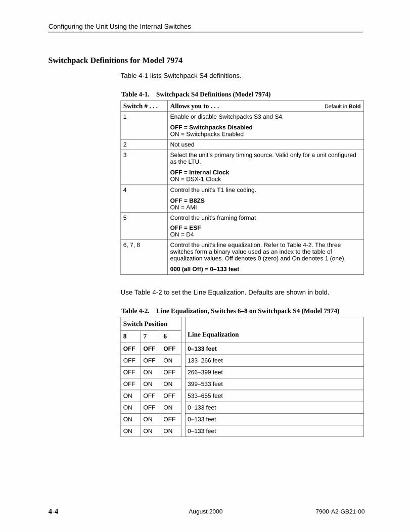
Table 4-1 lists Switchpack S4 definitions.
Table 4-1. Switchpack S4 Definitions (Model 7974)
Switch # . . . Allows you to . . . Default in Bold
1 Enable or disable Switchpacks S3 and S4.
OFF = Switchpacks DisabledON = Switchpacks Enabled
2 Not used
3 Select the unit’s primary timing source. Valid only for a unit configuredas the LTU.
OFF = Internal ClockON = DSX-1 Clock
4 Control the unit’s T1 line coding.
OFF = B8ZSON = AMI
5 Control the unit’s framing format
OFF = ESFON = D4
6, 7, 8 Control the unit’s line equalization. Refer to Table 4-2. The threeswitches form a binary value used as an index to the table ofequalization values. Off denotes 0 (zero) and On denotes 1 (one).
000 (all Off) = 0–133 feet
Use Table 4-2 to set the Line Equalization. Defaults are shown in bold.
Table 4-2. Line Equalization, Switches 6–8 on Switchpack S4 (Model 7974)
Switch Position
8 7 6 Line Equalization
OFF OFF OFF 0–133 feet
OFF OFF ON 133–266 feet
OFF ON OFF 266–399 feet
OFF ON ON 399–533 feet
ON OFF OFF 533–655 feet
ON OFF ON 0–133 feet
ON ON OFF 0–133 feet
ON ON ON 0–133 feet

Configuring the Unit Using the Internal Switches
4-57900-A2-GB21-00 August 2000
Table 4-3 lists Switchpack S3 definitions.
Table 4-3. Switchpack S3 Definitions (Model 7974)
Switch # . . . Allows you to . . . Default in Bold
1 Control whether the unit is an LTU or an NTU.
OFF = NTUON = LTU
2 Control whether the unit automatically adjusts to the best line rate forconditions, or is fixed at the rate set by Switches S3-3 through S3-5.
OFF = Fixed RateON = AutoRate Enabled
3, 4, 5 Control the DSL line rate of the unit. Refer to Table 4-4. If AutoRate isenabled, this switch represents the maximum DSL AutoRate value.
000 (all Off) = 1552 kbps
6 Control whether Telco loopbacks are supported.
OFF = EnabledON = Disabled
7 Control whether remote Telco loopbacks are supported.
OFF = DisabledON = Enabled
8 Emergency Use Only – Switch between two versions of firmware. Theunit has two banks of flash memory used to hold executable firmware.This switch allows you to change between the two versions of firmware.This switch is independent from the position of Switch 1 on SwitchpackS4 (switchpack enable/disable).
OFF = Current FirmwareON = Previous Firmware
Use Table 4-4 to set the DSL Line Rate. Defaults are shown in bold.
Table 4-4. DSL Line Rate, Switches 3–5 on Switchpack S3 (Model 7974)
Switch Position
5 4 3 DSL Line Rate
OFF OFF OFF 1552 kbps
OFF OFF ON 144 kbps
OFF ON OFF 272 kbps
OFF ON ON 400 kbps
ON OFF OFF 528 kbps
ON OFF ON 784 kbps
ON ON OFF 1040 kbps
ON ON ON 1552 kbps

Configuring the Unit Using the Internal Switches
4-6 7900-A2-GB21-00August 2000
Switchpack Definitions for Model 7975
Table 4-5 lists Switchpack S4 definitions.
Table 4-5. Switchpack S4 Definitions (Model 7975)
Switch # . . . Allows you to . . . Default in Bold
1 Enable or disable Switchpacks S3 and S4.
OFF = Switchpacks DisabledON = Switchpacks Enabled
2 Control Sync Port Type.
OFF = EIA-530, RS-449, or X.21ON = V.35
3 Select the unit’s timing source. Valid only for a unit configured as theLTU.
OFF = Internal clockON = External Clock
4, 5, 6, 7, 8 Control Sync Port Data Rate (refer to Table 4-6, Selectable PayloadRates)
NOTE: Switches 4 through 8 are only used when the unit isconfigured as an LTU and AutoRate is disabled.
All OFF = 2048 kbps (1024 kbps for 1 Mbps units)
Use Table 4-6 to set the Sync Port Payload Rate. Defaults are shown in bold.
NOTE:Sync Port and DSL Line Rates can only be selected from a unit configuredas the LTU (Switchpack S3 #1) with AutoRate disabled (Switchpack S3 #2).

Configuring the Unit Using the Internal Switches
4-77900-A2-GB21-00 August 2000
Table 4-6. Selectable Payload Rates (Model 7975)
Switchpack S4 Switch Number AssociatedDSL Line
Sync Port Payload Rate 8 7 6 5 4DSL LineRate
2048 kbps (32 x 64) OFF OFF OFF OFF OFF 2064 kbps
1984 kbps (31 x 64) ON ON ON ON ON 2064 kbps
1920 kbps (30 x 64) ON ON ON ON OFF 2064 kbps
1856 kbps (29 x 64) ON ON ON OFF ON 2064 kbps
1792 kbps (28 x 64) ON ON ON OFF OFF 2064 kbps
1728 kbps (27 x 64) ON ON OFF ON ON 2064 kbps
1664 kbps (26 x 64) ON ON OFF ON OFF 2064 kbps
1600 kbps (25 x 64) ON ON OFF OFF ON 2064 kbps
1536 kbps (24 x 64) ON ON OFF OFF OFF 1552 kbps
1472 kbps (23 x 64) ON OFF ON ON ON 1552 kbps
1408 kbps (22 x 64) ON OFF ON ON OFF 1552 kbps
1344 kbps (21 x 64) ON OFF ON OFF ON 1552 kbps
1280 kbps (20 x 64) ON OFF ON OFF OFF 1552 kbps
1216 kbps (19 x 64) ON OFF OFF ON ON 1552 kbps
1152 kbps (18 x 64) ON OFF OFF ON OFF 1552 kbps
1088 kbps (17 x 64) ON OFF OFF OFF ON 1552 kbps
1024 kbps (16 x 64) ON OFF OFF OFF OFF 1040 kbps
960 kbps (15 x 64) OFF ON ON ON ON 1040 kbps
896 kbps (14 x 64) OFF ON ON ON OFF 1040 kbps
832 kbps (13 x 64) OFF ON ON OFF ON 1040 kbps
768 kbps (12 x 64) OFF ON ON OFF OFF 784 kbps
704 kbps (11 x 64) OFF ON OFF ON ON 784 kbps
640 kbps (10 x 64) OFF ON OFF ON OFF 784 kbps
576 kbps (9 x 64) OFF ON OFF OFF ON 784 kbps
512 kbps (8 x 64) OFF ON OFF OFF OFF 528 kbps
448 kbps (7 x 64) OFF OFF ON ON ON 528 kbps
384 kbps (6 x 64) OFF OFF ON ON OFF 400 kbps
320 kbps (5 x 64) OFF OFF ON OFF ON 400 kbps
256 kbps (4 x 64) OFF OFF ON OFF OFF 272 kbps
192 kbps (3 x 64) OFF OFF OFF ON ON 272 kbps
128 kbps (2 x 64) OFF OFF OFF ON OFF 144 kbps
64 kbps (1 x 64) OFF OFF OFF OFF ON 144 kbps
NOTE:The 1 Mbps unit Payload Rate defaults to 1024 kbps (all OFF).
––––
––––
––––
–––
2 M
bp
s U
nit
s O
nly
–––
––––
––––
––––
Configuring the Unit Using the Internal Switches
4-8 7900-A2-GB21-00August 2000
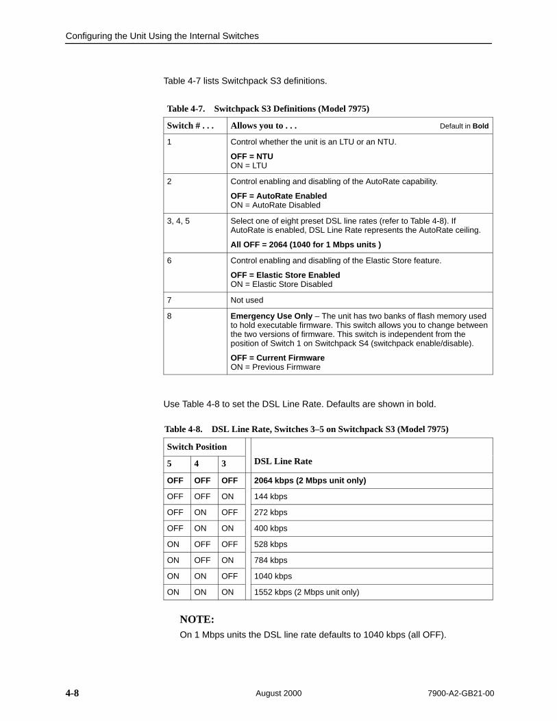
Table 4-7 lists Switchpack S3 definitions.
Table 4-7. Switchpack S3 Definitions (Model 7975)
Switch # . . . Allows you to . . . Default in Bold
1 Control whether the unit is an LTU or an NTU.
OFF = NTUON = LTU
2 Control enabling and disabling of the AutoRate capability.
OFF = AutoRate EnabledON = AutoRate Disabled
3, 4, 5 Select one of eight preset DSL line rates (refer to Table 4-8). IfAutoRate is enabled, DSL Line Rate represents the AutoRate ceiling.
All OFF = 2064 (1040 for 1 Mbps units )
6 Control enabling and disabling of the Elastic Store feature.
OFF = Elastic Store EnabledON = Elastic Store Disabled
7 Not used
8 Emergency Use Only – The unit has two banks of flash memory usedto hold executable firmware. This switch allows you to change betweenthe two versions of firmware. This switch is independent from theposition of Switch 1 on Switchpack S4 (switchpack enable/disable).
OFF = Current FirmwareON = Previous Firmware
Use Table 4-8 to set the DSL Line Rate. Defaults are shown in bold.
Table 4-8. DSL Line Rate, Switches 3–5 on Switchpack S3 (Model 7975)
Switch Position
5 4 3 DSL Line Rate
OFF OFF OFF 2064 kbps (2 Mbps unit only)
OFF OFF ON 144 kbps
OFF ON OFF 272 kbps
OFF ON ON 400 kbps
ON OFF OFF 528 kbps
ON OFF ON 784 kbps
ON ON OFF 1040 kbps
ON ON ON 1552 kbps (2 Mbps unit only)
NOTE:On 1 Mbps units the DSL line rate defaults to 1040 kbps (all OFF).
Configuring the Unit Using the Internal Switches
4-97900-A2-GB21-00 August 2000
Switchpack Definitions for Model 7976
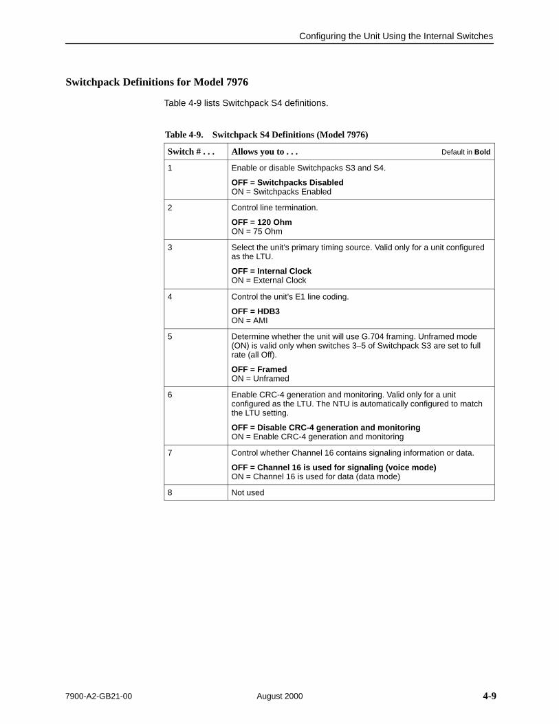
Table 4-9 lists Switchpack S4 definitions.
Table 4-9. Switchpack S4 Definitions (Model 7976)
Switch # . . . Allows you to . . . Default in Bold
1 Enable or disable Switchpacks S3 and S4.
OFF = Switchpacks DisabledON = Switchpacks Enabled
2 Control line termination.
OFF = 120 OhmON = 75 Ohm
3 Select the unit’s primary timing source. Valid only for a unit configuredas the LTU.
OFF = Internal ClockON = External Clock
4 Control the unit’s E1 line coding.
OFF = HDB3ON = AMI
5 Determine whether the unit will use G.704 framing. Unframed mode(ON) is valid only when switches 3–5 of Switchpack S3 are set to fullrate (all Off).
OFF = FramedON = Unframed
6 Enable CRC-4 generation and monitoring. Valid only for a unitconfigured as the LTU. The NTU is automatically configured to matchthe LTU setting.
OFF = Disable CRC-4 generation and monitoringON = Enable CRC-4 generation and monitoring
7 Control whether Channel 16 contains signaling information or data.
OFF = Channel 16 is used for signaling (voice mode)ON = Channel 16 is used for data (data mode)
8 Not used
Configuring the Unit Using the Internal Switches
4-10 7900-A2-GB21-00August 2000
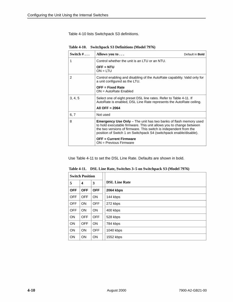
Table 4-10 lists Switchpack S3 definitions.
Table 4-10. Switchpack S3 Definitions (Model 7976)
Switch # . . . Allows you to . . . Default in Bold
1 Control whether the unit is an LTU or an NTU.
OFF = NTUON = LTU
2 Control enabling and disabling of the AutoRate capability. Valid only fora unit configured as the LTU.
OFF = Fixed RateON = AutoRate Enabled
3, 4, 5 Select one of eight preset DSL line rates. Refer to Table 4-11. IfAutoRate is enabled, DSL Line Rate represents the AutoRate ceiling.
All OFF = 2064
6, 7 Not used
8 Emergency Use Only – The unit has two banks of flash memory usedto hold executable firmware. This unit allows you to change betweenthe two versions of firmware. This switch is independent from theposition of Switch 1 on Switchpack S4 (switchpack enable/disable).
OFF = Current FirmwareON = Previous Firmware
Use Table 4-11 to set the DSL Line Rate. Defaults are shown in bold.
Table 4-11. DSL Line Rate, Switches 3–5 on Switchpack S3 (Model 7976)
Switch Position
5 4 3 DSL Line Rate
OFF OFF OFF 2064 kbps
OFF OFF ON 144 kbps
OFF ON OFF 272 kbps
OFF ON ON 400 kbps
ON OFF OFF 528 kbps
ON OFF ON 784 kbps
ON ON OFF 1040 kbps
ON ON ON 1552 kbps
5-17900-A2-GB21-00 August 2000
IP Addressing
5Selecting an IP Addressing Scheme
Your IP addressing scheme depends in part whether the Hotwire 797xStandalone Termination Unit is running in IP Conservative mode. The unit runs inIP Conservative mode if it is connected to a DSLAM card running in IPConservative mode.
Configurations Not Running IP Conservative Software
For a configuration not running IP Conservative software, the NTU’s networkinterface IP address is assigned through the peer IP address of the LTU’sNetwork Interface menu.
A DSLAM-mounted termination unit is assigned an IP address and subnetthrough the DSLAM Configuration → DSL Cards → Set IP Address menu. Oncethe address is assigned, you can use the ATI to assign:
Peer IP address. This address is used as the IP address of the remote unit.See Table A-1, Network Interface Options, in Appendix A, ConfigurationOptions.
An IP address for each NMS to act as a trap manager. See Table A-13, SNMP Traps Options, in Appendix A, Configuration Options.
All Configurations
The NTU obtains its IP address when the PPP link is established over the EOC.
Use the ATI to assign:
An IP address for each NMS. See Table A-12, SNMP NMS Security Options,in Appendix A, Configuration Options.
An IP address for the TFTP server you wish to use to upload and downloadconfigurations. See Configuration Loader in Chapter 3, Initial Startup andConfiguration, and the documentation for your TFTP server.

IP Addressing
5-2 7900-A2-GB21-00August 2000
The Peer IP Address refers to the EOC interface IP address of the unit configuredas an NTU. When the LTU and NTU negotiate a connection, the NTU receives itsaddress from the LTU.
Review the following information in preparation for selecting an IP addressingscheme.
Any legal host address is allowed for a given subnet. The address choicewithin the subnet is arbitrary.
The Peer IP Address must be unique within the MCC backplane subnet.
A single route to a subnet is all that is needed to reach every device on asubnet. The unit’s routing table supports a maximum of 20 routes.
IP Addressing Example
00-16040-04
DSLAM
DSLAM
797x
797x
797x
MCC BaseAddress = 126.35.50.1
MCC Base SubnetMask = 255.255.255.0
Port 1Peer IP Address = 126.35.1.5
MCCLTU877x
Port 2Peer IP Address = 126.35.1.4
Port 3Peer IP Address = 126.35.1.2
Port 4Peer IP Address = 126.35.1.3
NTUMCC
MCC BackplaneAddress = 126.35.1.1
MCC BackplaneMask = 255.255.255.0
LTU BackplaneAddress = 126.35.1.16
NTU BackplaneAddress = 126.35.50.2
Peer IP Address Assignments

6-17900-A2-GB21-00 August 2000
Security
6Overview
Security on the Hotwire 797x Standalone Termination Unit is implemented bylimiting user access to the ATI through option settings. You can:
Enable the Telnet Login Required option.
Enable the COM port Login Required option.
Limit access by setting a Session Access Level option of Operator for theTelnet session.
Limit access by setting a Session Access Level option of Operator for theCOM port.
Disable Telnet access with the Telnet Session option.
See Table A-8, Communication Port Options, and Table A-9, Telnet SessionOptions, in Appendix A, Configuration Options.

Security
6-2 7900-A2-GB21-00August 2000
ATI Access LevelsThe Hotwire 797x Standalone Termination Unit has two access levels:Administrator and Operator. The access level determines what functions areaccessible, as shown in Table 6-1.
Table 6-1. Access Levels
ATI Access to Menu Functions Administrator Operator
Status Read-Only Read-Only
Test Full Access No Access
Configuration Full Access Read-Only
Control Full Access No Access
Access levels can be applied to Login IDs, the COM port, and Telnet sessions.The effective access level is always the most restrictive:
When access is through the COM port and a login is required on the COMport, the effective access level is the more restrictive of the COM port accesslevel or the login access level. (See Table A-8, Communication Port Options.)
When access is through Telnet and a login is required for Telnet, the effectiveaccess level is the more restrictive of the Telnet session access level or thelogin access level. (See Table A-9, Telnet Session Options.)
When an access level of Operator is applied to the COM port and to Telnetsessions, a Login ID with Administrator authority is effectively reduced toOperator. It is no longer possible to change configuration options, and full accesscan be restored only by reloading factory defaults. (See Resetting the Unit’s COMPort or Factory Defaults on page 6-6.)

Security
6-37900-A2-GB21-00 August 2000
Creating a LoginLogins apply to the terminal directory connected to the communication port orTelnet access directly to the ATI of the unit.
Six login ID/password combinations are available. Each Login ID and Passwordmust be unique and include an access level.
Procedure
1. To create a login record, follow this menu selection sequence:
Main Menu →Control →Administer Logins
main/control/admin_logins Model: 797x
ADMINISTER LOGINS Page 1 of x
Login ID: newuserAccess Level: Administrator
–––––––––––––––––––––––––––––––––––––––––––––––––––––––––––––––––––––––––––––––– ESC for previous menu MainMenu Exit
Save New Delete
ÎÎ
ÎÎÎÎ
2. Select New and press Enter. The Login Entry screen appears.
main/control/admin_loginss/entry Model: 797x
LOGIN ENTRY
Login ID: newuser2 Password: es342 Re-enter Password: es342 Access Level: Administrator
WARNING New logins will not become permanent until saved
through the “ADMINISTER LOGINS” screen!
––––––––––––––––––––––––––––––––––––––––––––––––––––––––––––––––––––––––––––––––Ctrl-a to access these functions, ESC for previous menu MainMenu Exit Save
ÎÎ
ÎÎÎÎ
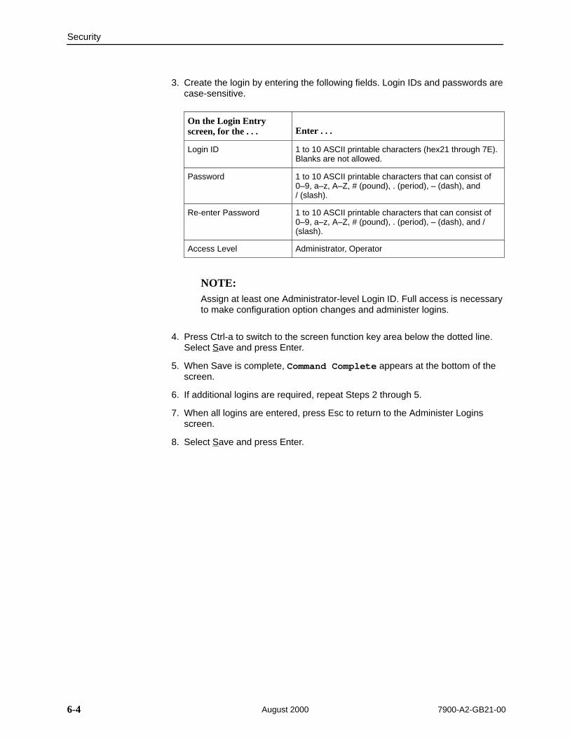
Security
6-4 7900-A2-GB21-00August 2000
3. Create the login by entering the following fields. Login IDs and passwords arecase-sensitive.
On the Login Entryscreen, for the . . . Enter . . .
Login ID 1 to 10 ASCII printable characters (hex21 through 7E).Blanks are not allowed.
Password 1 to 10 ASCII printable characters that can consist of0–9, a–z, A–Z, # (pound), . (period), – (dash), and / (slash).
Re-enter Password 1 to 10 ASCII printable characters that can consist of0–9, a–z, A–Z, # (pound), . (period), – (dash), and /(slash).
Access Level Administrator, Operator
NOTE:Assign at least one Administrator-level Login ID. Full access is necessaryto make configuration option changes and administer logins.
4. Press Ctrl-a to switch to the screen function key area below the dotted line.Select Save and press Enter.
5. When Save is complete, Command Complete appears at the bottom of thescreen.
6. If additional logins are required, repeat Steps 2 through 5.
7. When all logins are entered, press Esc to return to the Administer Loginsscreen.
8. Select Save and press Enter.
Security
6-57900-A2-GB21-00 August 2000
Deleting a Login
Procedure
1. To delete a login record, follow this menu selection sequence:
Main Menu →Control →Administer Logins
2. Select PgUp or PgDn and press Enter to page through login pages/recordsuntil you find the one to be deleted.
3. Once the correct record is displayed, select Delete and press Enter.
4. To complete the delete action, select Save and press Enter.
When the deletion is complete, Command Complete appears at the bottomof the screen. The number of login pages/records reflects one less record,and the record following the deleted record appears.

Security
6-6 7900-A2-GB21-00August 2000
Resetting the Unit’s COM Port or Factory Defaults
The user interface can be rendered inaccessible with a faulty configuration. Twomethods can be used to restore it:
Reset COM Port – Allows you to reset the configuration options related toCOM port usage. This also causes a device reset, where the termination unitperforms a Device Self-Test. No security-related configuration options arechanged.
Reload Factory Defaults – Allows you to reload the Default FactoryConfiguration, resetting all of the configuration and control settings whichcauses the current configuration to be destroyed and a device reset. Thismethod is also useful when the user’s password(s) have been forgotten.
Procedure
To reset COM port settings:
1. At a terminal directly connected to the unit’s COM port, configure the terminalto operate at 9.6 kbps, using character length of 8 bits, with one stop bit, andno parity.
2. Reset the unit, then immediately and repeatedly press Enter at a rate of atleast once per second until the System Paused screen appears.
3. Tab to the desired method, and enter yes (or y) for the selected prompt.
If entering yes to prompt . . . Then . . .
Reset COM Port usage Port type is set to Terminal
Data Rate (kbps) is set to 9.6
Character Length is set to 8
Stop Bits is set to 1
Parity is set to None
Reload Factory Defaults Yes (or y) will restore all factory-loadedconfiguration and control settings contained in theDefault Factory Configuration area are loaded.
If no (or n) is entered, or if no selection is made within 30 seconds, the unitreturns to the condition or operation it was in when the system reset wasinitiated, with the COM port rate returning to its configured rate.
The termination unit resets itself, going through a self-test. Connectivity isrestored and the Main Menu screen appears.

Security
6-77900-A2-GB21-00 August 2000
Controlling SNMP Access
There are three methods for limiting SNMP access:
Disable the SNMP management option. Refer to Table A-11, General SNMPManagement Options.
Assign SNMP community names and access types.
Limit SNMP access through validation of the IP address of each allowedSNMP manager.
Assigning SNMP Community Names and Access Types
The unit can be managed by an SNMP manager supporting SNMP. Thecommunity name must be supplied by an external SNMP manager accessing anobject in the MIB.
To define SNMP community names, follow this menu selection sequence:
Main Menu →Configuration →Load Configuration From →Edit →SNMP →General SNMP Management
Refer to Table A-11, General SNMP Management Options, to:
Enable SNMP Management.
Assign the SNMP community names of the SNMP Managers that are allowedto access the unit’s Management Information Base (MIB).
Specify Read or Read/Write access for each SNMP community name.
Limiting SNMP Access through the IP Addresses of the Managers
The unit provides an additional level of security through validation of the IPaddresses.
The SNMP Management option must be enabled. To control SNMP access withIP addresses, follow this menu selection sequence:
Main Menu →Configuration →Management →Security Menu
Refer to Table A-12, SNMP NMS Security Options. The SNMP access can belimited by:
Enabling NMS IP address checking.
Add each IP address and access level.
NOTES:— Do not change or delete the IP address or access level of the NMS
performing the sets or enable IP address checking prior to adding theNMS to the table.
— The SNMP NMS Security Options screen is not available if the unit isconnected to a DSLAM card running in IP Conservative mode.

Security
6-8 7900-A2-GB21-00August 2000
This page intentionally left blank.

7-17900-A2-GB21-00 August 2000
Monitoring and Troubleshooting
7What to Monitor
This chapter presents information on how to access and monitor HotwireStandalone Termination Units. You can monitor a unit’s operations by viewing the:
System and Test Status screen
Highest priority Health and Status message on the last line of the screen
Entry response messages on the last line of the screen
Network Error Statistics screen
Network Performance Statistics screen
DSX-1 or G.703 Statistics screen
Display LEDs screen or front panel LEDs on the Hotwire 797x StandaloneTermination Unit
The message tables in this chapter and Table 7-6, Troubleshooting, containsuggested actions for correction and recovery.

Monitoring and Troubleshooting
7-2 7900-A2-GB21-00August 2000
Viewing System and Test Status
To view System and Test Status information, follow this menu selectionsequence:
Main Menu →Status → System and Test Status
Î ÎÎ
main/status/system Model: 797x
SYSTEM AND TEST STATUS Page 1 of 1
HEALTH AND STATUS SELF-TEST RESULTS TEST STATUS–––––––––––––––––––––––––––––––––––––––––––––––––––––––––––––––––––––––––––––––System Operational Passed No Test Active
––––––––––––––––––––––––––––––––––––––––––––––––––––––––––––––––––––––––––––––– ESC for previous menu MainMenu ExitPgUp PgDn
The System and Test Status screen has three sections:
Health and Status – Displays messages in priority order (highest to lowest).Refer to Table 7-1, Health and Status Messages.
Self-Test Results – Results of the Diagnostic test run on the device itself.Refer to Table 7-2, Self-Test Results Messages.
Test Status – Currently active tests. Refer to Table 7-3, Test StatusMessages.

Monitoring and Troubleshooting
7-37900-A2-GB21-00 August 2000
Health and Status Messages
The following messages can appear in the first column of the System and TestStatus screen. The highest priority Health and Status message also appears onall ATI screens on the bottom right.
Table 7-1. Health and Status Messages (1 of 2)
Message What Message Indicates What To Do
AIS at DSX-1AIS at G.703
An Alarm Indication Signal(AIS) is being received bythe DSX-1 or G.703interface.
1. Verify that the unit’s line framingand line coding are compatible.
2. Contact network provider.
DeviceFailedyyyyyyyy
An internal error has beendetected by the operatingsoftware. yyyyyyyyindicates the 8-digithexadecimal failure code.
1. Provide the 8-digit failure codeshown (yyyyyyyy ) to your servicerepresentative.
2. Reset the unit to clear thecondition and message.
Download Failed A firmware download wasinterrupted.
Repeat the download.
EER at DSX-1EER at G.703
An EER (Excessive ErrorRate) condition has beendetected on the DSX-1 orG.703 interface.
1. Verify the attached equipmentcoding is compatible.
2. Verify your clock configuration.
3. Contact network provider.
EER at Net An EER (Excessive ErrorRate) condition has beendetected on the networkinterface at Port 1. Thecondition is cleared whenthe error rate falls belowthe threshold valuecurrently configured.
1. Ignore condition if 511 test active.
2. Contact network provider.
Fallback Rate The LTU had a loss ofsignal, and when the linewas restored it did notresynchronize to the lastknown rate, but to a lowerrate.
1. Verify that the network cable issecurely attached at both ends.
2. From the Control screen, selectReset AutoRate to see if the unitwill retrain at a higher rate.
3. Contact network provider.
LOF at DSX-1LOF at G.703
An LOF (Loss Of Frame)condition has beendetected on the DSX-1 orG.703 interface.
1. Verify that the network cable issecurely attached at both ends.
2. Contact network provider.
LOS at DSX-1LOS at G.703
An LOS (Loss Of Signal)condition has beendetected on the DSX-1 orG.703 interface.
1. Verify proper framing.
2. Contact network provider.
LOS at Net, Pt 1 An LOS (Loss Of Signal)condition has beendetected on the networkinterface.
1. Verify that the network cable issecurely attached at both ends.
2. Contact network provider.
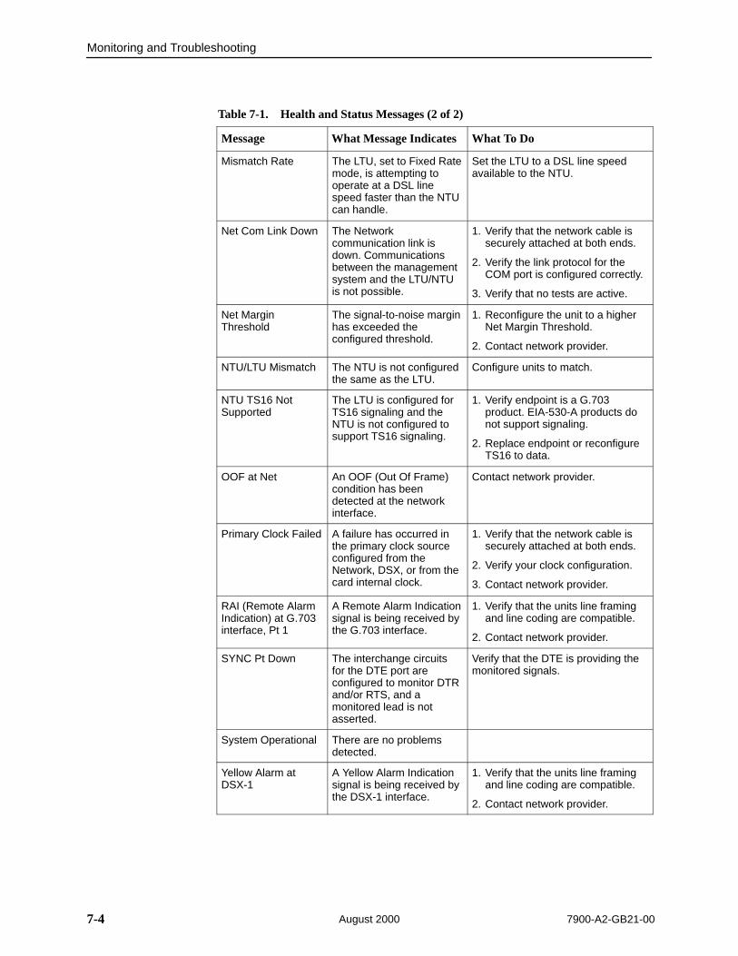
Monitoring and Troubleshooting
7-4 7900-A2-GB21-00August 2000
Table 7-1. Health and Status Messages (2 of 2)
Message What To DoWhat Message Indicates
Mismatch Rate The LTU, set to Fixed Ratemode, is attempting tooperate at a DSL linespeed faster than the NTUcan handle.
Set the LTU to a DSL line speedavailable to the NTU.
Net Com Link Down The Networkcommunication link isdown. Communicationsbetween the managementsystem and the LTU/NTUis not possible.
1. Verify that the network cable issecurely attached at both ends.
2. Verify the link protocol for theCOM port is configured correctly.
3. Verify that no tests are active.
Net MarginThreshold
The signal-to-noise marginhas exceeded theconfigured threshold.
1. Reconfigure the unit to a higherNet Margin Threshold.
2. Contact network provider.
NTU/LTU Mismatch The NTU is not configuredthe same as the LTU.
Configure units to match.
NTU TS16 NotSupported
The LTU is configured forTS16 signaling and theNTU is not configured tosupport TS16 signaling.
1. Verify endpoint is a G.703product. EIA-530-A products donot support signaling.
2. Replace endpoint or reconfigureTS16 to data.
OOF at Net An OOF (Out Of Frame)condition has beendetected at the networkinterface.
Contact network provider.
Primary Clock Failed A failure has occurred inthe primary clock sourceconfigured from theNetwork, DSX, or from thecard internal clock.
1. Verify that the network cable issecurely attached at both ends.
2. Verify your clock configuration.
3. Contact network provider.
RAI (Remote AlarmIndication) at G.703interface, Pt 1
A Remote Alarm Indicationsignal is being received bythe G.703 interface.
1. Verify that the units line framingand line coding are compatible.
2. Contact network provider.
SYNC Pt Down The interchange circuitsfor the DTE port areconfigured to monitor DTRand/or RTS, and amonitored lead is notasserted.
Verify that the DTE is providing themonitored signals.
System Operational There are no problemsdetected.
Yellow Alarm atDSX-1
A Yellow Alarm Indicationsignal is being received bythe DSX-1 interface.
1. Verify that the units line framingand line coding are compatible.
2. Contact network provider.
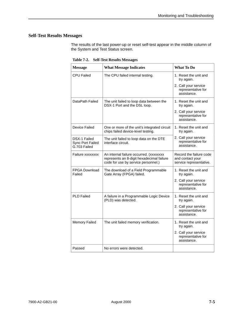
Monitoring and Troubleshooting
7-57900-A2-GB21-00 August 2000
Self-Test Results Messages
The results of the last power-up or reset self-test appear in the middle column ofthe System and Test Status screen.
Table 7-2. Self-Test Results Messages
Message What Message Indicates What To Do
CPU Failed The CPU failed internal testing. 1. Reset the unit andtry again.
2. Call your servicerepresentative forassistance.
DataPath Failed The unit failed to loop data between theDSX-1 Port and the DSL loop.
1. Reset the unit andtry again.
2. Call your servicerepresentative forassistance.
Device Failed One or more of the unit’s integrated circuitchips failed device-level testing.
1. Reset the unit andtry again.
DSX-1 FailedSync Port FailedG.703 Failed
The unit failed to loop data on the DTEinterface circuit.
2. Call your servicerepresentative forassistance.
Failure xxxxxxxx An internal failure occurred. (xxxxxxxxrepresents an 8-digit hexadecimal failurecode for use by service personnel.)
Record the failure codeand contact yourservice representative.
FPGA DownloadFailed
The download of a Field ProgrammableGate Array (FPGA) failed.
1. Reset the unit andtry again.
2. Call your servicerepresentative forassistance.
PLD Failed A failure in a Programmable Logic Device(PLD) was detected.
1. Reset the unit andtry again.
2. Call your servicerepresentative forassistance.
Memory Failed The unit failed memory verification. 1. Reset the unit andtry again.
2. Call your servicerepresentative forassistance.
Passed No errors were detected.
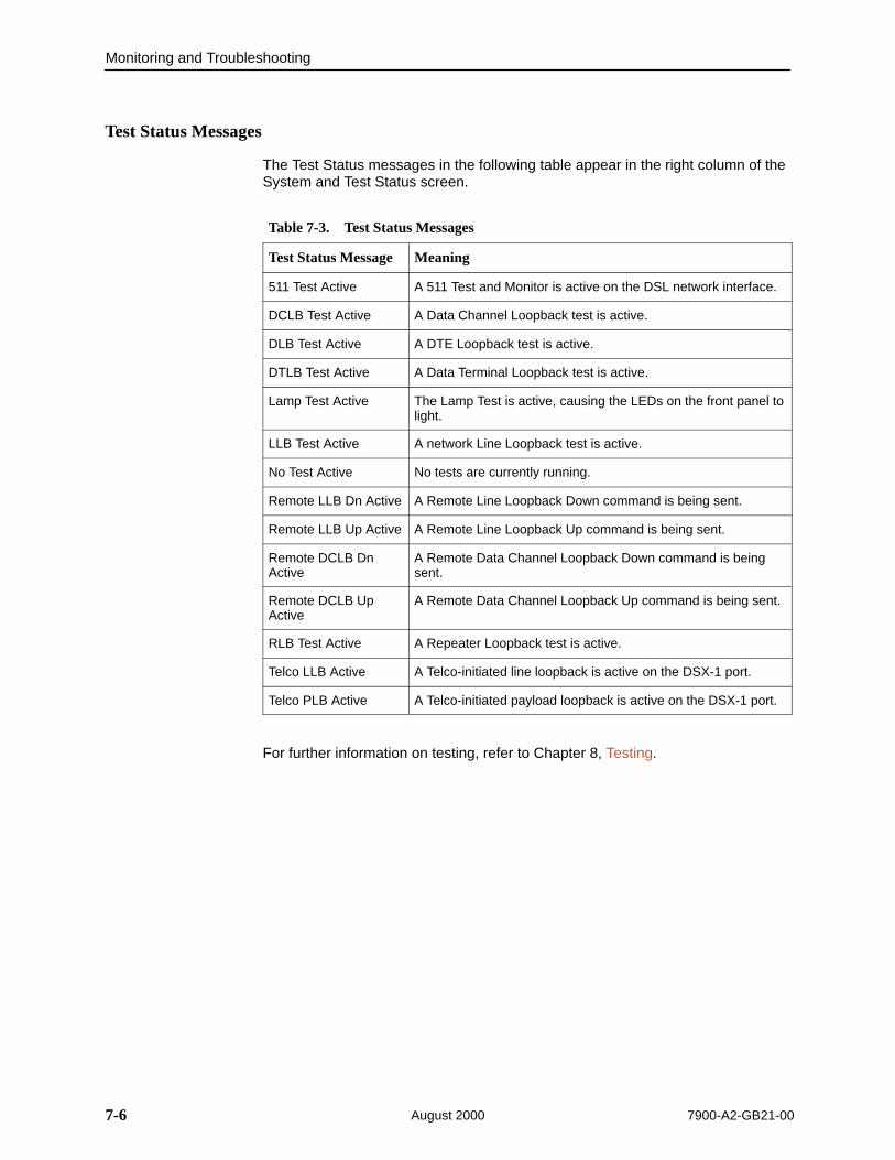
Monitoring and Troubleshooting
7-6 7900-A2-GB21-00August 2000
Test Status Messages
The Test Status messages in the following table appear in the right column of theSystem and Test Status screen.
Table 7-3. Test Status Messages
Test Status Message Meaning
511 Test Active A 511 Test and Monitor is active on the DSL network interface.
DCLB Test Active A Data Channel Loopback test is active.
DLB Test Active A DTE Loopback test is active.
DTLB Test Active A Data Terminal Loopback test is active.
Lamp Test Active The Lamp Test is active, causing the LEDs on the front panel tolight.
LLB Test Active A network Line Loopback test is active.
No Test Active No tests are currently running.
Remote LLB Dn Active A Remote Line Loopback Down command is being sent.
Remote LLB Up Active A Remote Line Loopback Up command is being sent.
Remote DCLB DnActive
A Remote Data Channel Loopback Down command is beingsent.
Remote DCLB UpActive
A Remote Data Channel Loopback Up command is being sent.
RLB Test Active A Repeater Loopback test is active.
Telco LLB Active A Telco-initiated line loopback is active on the DSX-1 port.
Telco PLB Active A Telco-initiated payload loopback is active on the DSX-1 port.
For further information on testing, refer to Chapter 8, Testing.

Monitoring and Troubleshooting
7-77900-A2-GB21-00 August 2000
Entry Response Messages
The messages in Table 7-4, listed in alphabetical order, can appear in themessages area at the bottom of ATI screens in response to commands or dataentry.
Table 7-4. Entry Response Messages (1 of 2)
Device Message What Message Indicates What To Do
0.0.0.0 is an invalid IP address
An IP address of all zeroswas entered.
Enter a valid, non-zero IPaddress.
Access level isOperator.Configuration isread-only.
The operator requested thatconfiguration options beloaded, but does not haveauthority to edit them.
If configuration options are to beedited, use a Login ID that hasAdministrator authority.
Cannot Save – noLogin IDs with AccessAdministrator
All of the login IDs beingsaved have an access levelbelow Administrator.
Change the access level of atleast one Login ID toAdministrator so thatconfiguration changes can bemade. (Operator-level userscannot make configurationchanges.) Save the Login IDs.
Command Complete Action requested hassuccessfully completed.
No action needed.
Invalid Character A nonprintable ASCIIcharacter has beenentered.
Reenter information using validcharacters.
Invalid – DataTerminal InitiatedLoopback Active
Network-initiated loopbackwas in progress when theselection was made.
No action needed.
Invalid entry at cursor Invalid IP address for thisfunction.
Enter a valid IP address. See theappropriate table in Appendix A,Configuration Options, todetermine the permitted addressrange for this field.
Invalid Password Login is required and anincorrect password or LoginID was entered; access isdenied.
Enter the correct Login ID andpassword combination.
Contact your systemadministrator to verify yourLogin ID and password.
Invalid – [Test ]Already Active
The described test wasalready in progress whenthe selection was made.
Allow test to continue.
Select another test.
Stop the test.

Monitoring and Troubleshooting
7-8 7900-A2-GB21-00August 2000
Table 7-4. Entry Response Messages (2 of 2)
Device Message What To DoWhat Message Indicates
Invalid TestCombination
A loopback or pattern testwas in progress when Startwas selected to start thetest, or was active on thesame interface when thetest was selected.
Wait until other test ends.
Abort all tests from the Testmenu screen.
Stop the test from the samescreen the test was startedfrom.
Limit of six Login IDsreached
An attempt to enter a newlogin ID was made, and thelimit of six login/passwordcombinations has beenreached.
1. Delete another login/passwordcombination.
2. Reenter the new login ID.
No Security Recordsto Delete
Delete was selected fromthe Administer Loginscreen, and no securityrecords had been defined.
No action needed.
Enter a security record.
Password MatchingError – Re-enterPassword
Password entered in theReenter Password field ofthe Administer Loginsscreen does not matchwhat was entered in thePassword field.
Try again.
Please Wait Command takes longerthan 5 seconds.
Wait until message clears.
Test Active A test is running and nohigher priority health andstatus messages exist.
Contact service provider if testinitiated by the network.
Wait until the other test endsand message clears.
Cancel all tests from the Testscreen.
Stop the test from the samescreen the test was startedfrom.

Monitoring and Troubleshooting
7-97900-A2-GB21-00 August 2000
Viewing Network Error Statistics
The Hotwire 797x Standalone Termination Unit maintains error statistics on thenetwork DSL interface. Statistics are maintained for up to 96 15-minute intervals(24 hours).
To view the Network Error Statistics, follow this menu selection sequence:
Main Menu →Status →Performance →Network Error Statistics
ÎÎÎÎÎÎÎÎÎÎÎÎÎÎÎÎÎÎÎÎÎÎÎÎÎÎÎÎÎÎÎÎÎÎÎÎÎÎÎÎÎÎÎÎÎÎÎÎÎÎÎÎÎÎÎÎÎÎÎÎÎÎÎÎÎÎÎÎÎÎÎÎÎÎÎÎÎÎÎÎÎÎÎÎÎÎÎÎÎÎÎÎÎÎÎÎÎÎÎÎÎÎÎÎÎÎÎÎÎÎÎÎÎÎÎÎÎÎÎÎÎÎÎÎÎÎÎÎÎÎÎÎÎÎÎÎÎÎÎÎÎÎÎÎÎÎÎÎÎÎÎÎÎÎÎÎÎÎÎÎÎÎÎÎÎÎÎÎÎÎÎÎÎÎÎÎÎÎÎÎÎÎÎÎÎÎÎÎÎÎÎÎÎÎÎÎÎÎÎÎÎÎÎÎÎÎÎÎÎÎÎÎÎÎÎÎÎÎÎÎÎÎÎÎÎÎÎÎÎÎÎÎÎÎÎÎÎÎÎÎÎÎÎÎÎÎÎÎÎÎÎÎÎÎÎÎÎÎÎÎÎÎÎÎÎÎÎÎÎÎÎÎÎÎÎÎÎÎÎÎÎÎÎÎÎÎÎÎÎÎÎÎÎÎÎÎÎÎÎÎÎÎÎÎÎÎÎÎÎÎÎÎÎÎÎÎÎÎÎÎÎÎÎÎÎÎÎÎÎÎÎÎÎÎÎÎÎÎÎÎÎÎÎÎÎÎÎÎÎÎÎÎÎÎÎÎÎÎÎÎÎÎÎÎÎÎÎÎÎÎÎÎÎÎÎÎÎÎÎÎÎÎÎÎÎÎÎÎÎÎÎÎÎÎÎÎÎÎÎÎ
main/status/performance/net_error Model: 797x NETWORK ERROR STATISTICS
Current Interval Timer: 002 Error Events Counter: 0034––––––––––––––––––––––––––––––––––––––––––––––––––––––––––––––––––––––––––––––– –––ES––– –––SES––– ––FEBE–– –Complete–
Near Far Near Far Near Far Near Far Current Int: 000 000 000 000 000 000 Yes No Interval 01 000 000 000 000 000 000 Yes Yes Interval 02 000 000 000 000 000 000 Yes Yes Interval 03 000 000 000 000 000 000 Yes Yes Interval 04 000 000 000 000 000 000 Yes Yes Interval 05 000 000 000 000 000 000 Yes Yes Interval 06 000 000 000 000 000 000 Yes Yes Interval 07 000 000 000 000 000 000 Yes Yes
Worst Interval: 24 09 14 08 18 18Near Tot(valid): 00010 00000 00000 Far Tot(valid): 00010 00000 00000–––––––––––––––––––––––––––––––––––––––––––––––––––––––––––––––––––––––––––––––Ctrl–a to access these functions, ESC for previous menu MainMenu Exit PgUp PgDn ClrNear ClrFar
Select PgUp or PgDn to view more statistics. Select ClrNear or ClrFar to clearthe near- and far-end statistics to zero.

Monitoring and Troubleshooting
7-10 7900-A2-GB21-00August 2000
Network Error Statistics are collected for:
ES (Errored Seconds): Seconds during which one or more CRC errorevents occurred.
SES (Severely Errored Seconds): Seconds during which more than 320 cyclic redundancy check (CRC) error events or at least one Out of Frame(OOF) event occurred.
FEBE (Far-End Block Errors): Errors reported by the remote equipment.
Complete: Whether the interval register contains data for a complete 900-second interval.
Use the virtual function keys to page through the intervals and clear statistics.
This Field . . . Contains . . .
Current IntervalTimer
The number of seconds which have elapsed in the current15-minute interval. Maximum value is 900 seconds (15 minutes).This counter resets every 15 minutes.
Error EventsCounter
A running total of CRC errors. Range 0–65535. This counterresets when the near-end data is cleared.
Current Int Performance data for the current 15-minute interval.
Interval xx Historical performance data for up to 96 15-minute intervals (24 hours) where the value of xx is from 01 to 96.
Worst Interval The number of the interval with the worst (highest) performancedata for both the near- and far-end statistics. If two or moreintervals are equal, the oldest interval is displayed.
Near and Far Tot A 24-hour running total of the near- and far-end performancestatistics.
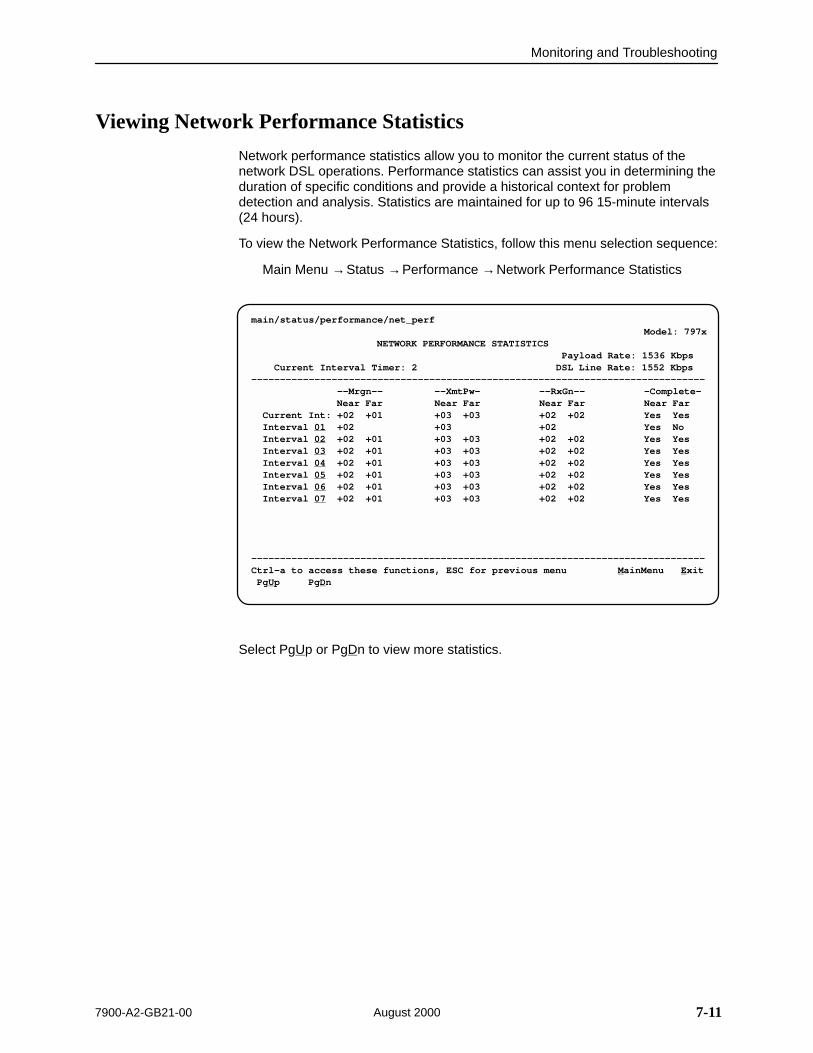
Monitoring and Troubleshooting
7-117900-A2-GB21-00 August 2000
Viewing Network Performance Statistics
Network performance statistics allow you to monitor the current status of thenetwork DSL operations. Performance statistics can assist you in determining theduration of specific conditions and provide a historical context for problemdetection and analysis. Statistics are maintained for up to 96 15-minute intervals(24 hours).
To view the Network Performance Statistics, follow this menu selection sequence:
Main Menu →Status →Performance →Network Performance Statistics
ÎÎÎÎÎÎÎÎÎÎÎÎÎÎÎÎÎÎÎÎÎÎÎÎÎÎÎÎÎÎÎÎÎÎÎÎÎÎÎÎÎÎÎÎÎÎÎÎÎÎÎÎÎÎÎÎÎÎÎÎÎÎÎÎÎÎÎÎÎÎÎÎÎÎÎÎÎÎÎÎÎÎÎÎÎÎÎÎÎÎÎÎÎÎÎÎÎÎÎÎÎÎÎÎÎÎÎÎÎÎÎÎÎÎÎÎÎÎÎÎÎÎÎÎÎÎÎÎÎÎÎÎÎÎÎÎÎÎÎÎÎÎÎÎÎÎÎÎÎÎÎÎÎÎÎÎÎÎÎÎÎÎÎÎÎÎÎÎÎÎÎÎÎÎÎÎÎÎÎÎÎÎÎÎÎÎÎÎÎÎÎÎÎÎÎÎÎÎÎÎÎÎÎÎÎÎÎÎÎÎÎÎÎÎÎÎÎÎÎÎÎÎÎÎÎÎÎÎÎÎÎÎÎÎÎÎÎÎÎÎÎÎÎÎÎÎÎÎÎÎÎÎÎÎÎÎÎÎÎÎÎÎÎÎÎÎÎÎÎÎÎÎÎÎÎÎÎÎÎÎÎÎÎÎÎÎÎÎÎÎÎÎÎÎÎÎÎÎÎÎÎÎÎÎÎÎÎÎÎÎÎÎÎÎÎÎÎÎÎÎÎÎÎÎÎÎÎÎÎÎÎÎÎÎÎÎÎÎÎÎÎÎÎÎÎÎÎÎÎÎÎÎÎÎÎÎÎÎÎÎÎÎÎÎÎÎÎÎÎÎÎÎÎÎÎÎÎÎÎÎÎÎÎÎÎÎÎÎÎÎÎÎÎÎÎÎÎÎÎÎ
main/status/performance/net_perf Model: 797x NETWORK PERFORMANCE STATISTICS
Payload Rate: 1536 Kbps Current Interval Timer: 2 DSL Line Rate: 1552 Kbps––––––––––––––––––––––––––––––––––––––––––––––––––––––––––––––––––––––––––––––– ––Mrgn–– ––XmtPw– ––RxGn–– –Complete–
Near Far Near Far Near Far Near Far Current Int: +02 +01 +03 +03 +02 +02 Yes Yes Interval 01 +02 +03 +02 Yes No Interval 02 +02 +01 +03 +03 +02 +02 Yes Yes Interval 03 +02 +01 +03 +03 +02 +02 Yes Yes Interval 04 +02 +01 +03 +03 +02 +02 Yes Yes Interval 05 +02 +01 +03 +03 +02 +02 Yes Yes Interval 06 +02 +01 +03 +03 +02 +02 Yes Yes Interval 07 +02 +01 +03 +03 +02 +02 Yes Yes
–––––––––––––––––––––––––––––––––––––––––––––––––––––––––––––––––––––––––––––––Ctrl–a to access these functions, ESC for previous menu MainMenu Exit PgUp PgDn
Select PgUp or PgDn to view more statistics.

Monitoring and Troubleshooting
7-12 7900-A2-GB21-00August 2000
Network Performance Statistics are collected for:
Mrgn: Signal to Noise Ratio (SNR) Margin is the difference of the SNR,measured every 10 seconds, and a set SNR reference value. The acceptablerange for SNR Margin is 0 and above. However, it may be practical to toleratevalues below 0 on bad lines or longer reaches.
XmtPw: The transmit power level. The maximum level is 15 dBm.
RxGn: The receiver gain level. This is the amount the unit must boost thereceive signal. It is not a receive level measurement.
Complete: Whether the interval register contains data for a complete 900-second interval.
This Field . . . Contains . . .
Current IntervalTimer
The number of seconds which have elapsed in the current15-minute interval. Maximum value is 900 seconds (15 minutes).This counter resets every 15 minutes.
Payload Rate The Payload Rate across the DSL interface.
DSL Line Rate The rate of the DSL line (400 to 1552 kbps).
Current Int Performance data for the current 15-minute interval.
Interval xx Historical performance data for up to 96 15-minute intervals (24 hours) where the value of xx is from 01 to 96.

Monitoring and Troubleshooting
7-137900-A2-GB21-00 August 2000
Viewing DSX-1 Performance Statistics (Model 7974)
DSX-1 performance statistics allow you to monitor the current status of the DSX-1interface operations when ESF framing is selected. Performance statistics canassist you in determining the duration of specific conditions and provide ahistorical context for problem detection and analysis. Statistics are maintained forup to 96 15-minute intervals (24 hours).
To view the Network Performance Statistics, follow this menu selection sequence:
Main Menu →Status →Performance →DSX-1 Performance Statistics
ÎÎÎÎÎÎÎÎÎÎÎÎÎÎÎÎÎÎÎÎÎÎÎÎÎÎÎÎÎÎÎÎÎÎÎÎÎÎÎÎÎÎÎÎÎÎÎÎÎÎÎÎÎÎÎÎÎÎÎÎÎÎÎÎÎÎÎÎÎÎÎÎÎÎÎÎÎÎÎÎÎÎÎÎÎÎÎÎÎÎÎÎÎÎÎÎÎÎÎÎÎÎÎÎÎÎÎÎÎÎÎÎÎÎÎÎÎÎÎÎÎÎÎÎÎÎÎÎÎÎÎÎÎÎÎÎÎÎÎÎÎÎÎÎÎÎÎÎÎÎÎÎÎÎÎÎÎÎÎÎÎÎÎÎÎÎÎÎÎÎÎÎÎÎÎÎÎÎÎÎÎÎÎÎÎÎÎÎÎÎÎÎÎÎÎÎÎÎÎÎÎÎÎÎÎÎÎÎÎÎÎÎÎÎÎÎÎÎÎÎÎÎÎÎÎÎÎÎÎÎÎÎÎÎÎÎÎÎÎÎÎÎÎÎÎÎÎÎÎÎÎÎÎÎÎÎÎÎÎÎÎÎÎÎÎÎÎÎÎÎÎÎÎÎÎÎÎÎÎÎÎÎÎÎÎÎÎÎÎÎÎÎÎÎÎÎÎÎÎÎÎÎÎÎÎÎÎÎÎÎÎÎÎÎÎÎÎÎÎÎÎÎÎÎÎÎÎÎÎÎÎÎÎÎÎÎÎÎÎÎÎÎÎÎÎÎÎÎÎÎÎÎÎÎÎÎÎÎÎÎÎÎÎÎÎÎÎÎÎÎÎÎÎÎÎ
main/status/performance/DSX-1 Model: 7974 DSX-1 PERFORMANCE STATISTICS
Current Interval Timer: 2 Error Events Counter: 0000––––––––––––––––––––––––––––––––––––––––––––––––––––––––––––––––––––––––––––––– ––ES–– ––UAS–– ––SES–– ––BES–– ––CSS–– –LOFC– –Status–
Current Int: 000 000 000 000 000 000 YInterval 01 000 000 000 000 000 000 noneInterval 02 000 000 000 000 000 000 noneInterval 03 000 000 000 000 000 000 noneInterval 04 000 000 000 000 000 000 noneInterval 05 000 000 000 000 000 000 noneInterval 06 000 000 000 000 000 000 noneInterval 07 000 000 000 000 000 000 none
Worst Interval: 24 14 14 09 18 12Tot (valid 96): 00010 00000 00000 00000 0020 0000
–––––––––––––––––––––––––––––––––––––––––––––––––––––––––––––––––––––––––––––––Ctrl–a to access these functions, ESC for previous menu MainMenu Exit PgUp PgDn ClrStats
Select PgUp or PgDn to view the next or previous seven intervals. Select ClrStatsto clear all statistics to zero.

Monitoring and Troubleshooting
7-14 7900-A2-GB21-00August 2000
DSX-1 Performance Statistics are collected for:
ES (Errored Seconds): Seconds during which one or more error eventsoccurred.
UAS (Unavailable Seconds): Seconds during which service is unavailable.UAS is received at the start of 10 consecutive SES and cleared at the start of10 seconds with no SES.
SES (Severely Errored Seconds): Seconds during which 320 or more cyclicredundancy check (CRC) error events or at least one Out of Frame (OOF)event occurred.
BES (Bursty Errored Seconds): Contains the number of bursty erroredseconds for the current interval. A bursty errored second is any second withmore than one but less than 320 CRC errors.
CSS (Controlled Slip Seconds): Seconds during which one or morecontrolled slips (as defined in TR 54016) occurred.
LOFC (Loss of Frame Count): Contains the number of times that an LOF isdeclared.
Status: Contains the contents of the status events register. The status eventsregister maintains a history of specific events that have occurred during aninterval. Values include:
— Y: Remote alarm indication signal (yellow alarm) received at the DSX-1interface
— L: Loss of signal detected at the DSX-1 interface
— E: Excessive error rate threshold exceeded
— F: Frame synchronization bit error detected
— V: Line code violation detected
— None: No significant events have occurred
This Field . . . Contains . . .
Current IntervalTimer
The number of seconds which have elapsed in the current15-minute interval. Maximum value is 900 seconds (15 minutes).This counter resets every 15 minutes.
Error EventsCounter
A running total of CRC and OOF events. Total range = 0–65535.Counter resets when the statistics are cleared.
Current Int Performance data for the current 15-minute interval.
Interval xx Historical performance data for up to 96 15-minute intervals (24 hours) where the value of xx is from 01 to 96.
Worst Interval The number of the interval with the worst (highest) performancedata. If two or more intervals are equal, the oldest interval isdisplayed.
Tot A 24-hour running total.

Monitoring and Troubleshooting
7-157900-A2-GB21-00 August 2000
Viewing G.703 Performance Statistics(Model 7976)
G.703 performance statistics allow you to monitor the current status of the G.703interface operations. Performance statistics can assist you in determining theduration of specific conditions and provide a historical context for problemdetection and analysis. Statistics are maintained for up to 96 15-minute intervals(24 hours).
To view the Network Performance Statistics, follow this menu selection sequence:
Main Menu →Status →Performance →G.703 Performance Statistics
ÎÎÎÎÎÎÎÎÎÎÎÎÎÎÎÎÎÎÎÎÎÎÎÎÎÎÎÎÎÎÎÎÎÎÎÎÎÎÎÎÎÎÎÎÎÎÎÎÎÎÎÎÎÎÎÎÎÎÎÎÎÎÎÎÎÎÎÎÎÎÎÎÎÎÎÎÎÎÎÎÎÎÎÎÎÎÎÎÎÎÎÎÎÎÎÎÎÎÎÎÎÎÎÎÎÎÎÎÎÎÎÎÎÎÎÎÎÎÎÎÎÎÎÎÎÎÎÎÎÎÎÎÎÎÎÎÎÎÎÎÎÎÎÎÎÎÎÎÎÎÎÎÎÎÎÎÎÎÎÎÎÎÎÎÎÎÎÎÎÎÎÎÎÎÎÎÎÎÎÎÎÎÎÎÎÎÎÎÎÎÎÎÎÎÎÎÎÎÎÎÎÎÎÎÎÎÎÎÎÎÎÎÎÎÎÎÎÎÎÎÎÎÎÎÎÎÎÎÎÎÎÎÎÎÎÎÎÎÎÎÎÎÎÎÎÎÎÎÎÎÎÎÎÎÎÎÎÎÎÎÎÎÎÎÎÎÎÎÎÎÎÎÎÎÎÎÎÎÎÎÎÎÎÎÎÎÎÎÎÎÎÎÎÎÎÎÎÎÎÎÎÎÎÎÎÎÎÎÎÎÎÎÎÎÎÎÎÎÎÎÎÎÎÎÎÎÎÎÎÎÎÎÎÎÎÎÎÎÎÎÎÎÎÎÎÎÎÎÎÎÎÎÎÎÎÎÎÎÎÎÎÎÎÎÎÎÎÎÎÎÎÎÎÎÎ
main/status/performance/G.703 Model: 7976 G.703 PERFORMANCE STATISTICS
Current Interval Timer: 004 Error Events Counter: 012––––––––––––––––––––––––––––––––––––––––––––––––––––––––––––––––––––––––––––––– ––ES–– ––UAS–– ––SES–– ––BES–– ––CSS–– –LOF– –Status–
Current Int: 000 000 000 000 000 000 YInterval 01 000 000 000 000 000 000 noneInterval 02 000 000 000 000 000 000 noneInterval 03 000 000 000 000 000 000 noneInterval 04 000 000 000 000 000 000 noneInterval 05 000 000 000 000 000 000 noneInterval 06 000 000 000 000 000 000 noneInterval 07 000 000 000 000 000 000 none
Worst Interval: 24 14 14 09 18 12Tot (valid 96): 00010 00000 00000 00000 0020 0000
–––––––––––––––––––––––––––––––––––––––––––––––––––––––––––––––––––––––––––––––Ctrl–a to access these functions, ESC for previous menu MainMenu Exit PgUp PgDn ClrStats
Select PgUp or PgDn to view the next or previous seven intervals. Select ClrStatsto clear all statistics to zero.
Monitoring and Troubleshooting
7-16 7900-A2-GB21-00August 2000
G.703 Performance Statistics are collected for:
ES (Errored Seconds): Seconds during which one or more error eventsoccurred.
UAS (Unavailable Seconds): Seconds during which service is unavailable.UAS is received at the start of 10 consecutive SES and cleared at the start of10 seconds with no SES.
SES (Severely Errored Seconds): Seconds during which more than 805 cyclic redundancy check (CRC) error events, more than 16 FAS errors,or at least one Out of Frame (OOF) event occurred.
BES (Bursty Errored Seconds): Contains the number of bursty erroredseconds for the current interval. A bursty errored second is any second withmore than one but less than 805 CRC errors (CRC Mode) or more than onebut less than 16 FAS errors (non-CRC mode).
CSS (Controlled Slip Seconds): Seconds during which one or morecontrolled slips (as defined in TR 54016) occurred.
LOF (Loss of Frame Seconds): Contains the number of seconds thatcontain one or more LOF events.
Status: Contains the contents of the status events register. The status eventsregister maintains a history of specific events that have occurred during aninterval. Values include:
— Y: Remote alarm indication signal received at the G.703 interface
— L: Loss of signal detected at the G.703 interface
— E: Excessive error rate threshold exceeded
— F: Frame synchronization bit error detected
— V: Line code violation detected
— None: No significant events have occurred
This Field . . . Contains . . .
Current IntervalTimer
The number of seconds which have elapsed in the current15-minute interval. Maximum value is 900 seconds (15 minutes).This counter resets every 15 minutes.
Error EventsCounter
A running total of CRC and OOF events. Total range = 0–65535.Counter resets when the statistics are cleared.
Current Int Performance data for the current 15-minute interval.
Interval xx Historical performance data for up to 96 15-minute intervals (24 hours) where the value of xx is from 01 to 96.
Worst Interval The number of the interval with the worst (highest) performancedata. If two or more intervals are equal, the oldest interval isdisplayed.
Tot A 24-hour running total.

Monitoring and Troubleshooting
7-177900-A2-GB21-00 August 2000
Using the Display LEDs ScreenThe Hotwire 797x Standalone Termination Unit LEDs can be viewed on theDisplay LEDs status screen. This ATI status screen is available locally andremotely.
There are three classes of LEDs:
General LEDs display the status of the unit
The DTE (DSX-1, Sync Port, or G.703) LED provides the status of the DTEinterface
The DSL Loop LED displays the activity on the DSL network
To view the Display LEDs status screen, follow this menu selection sequence:
Main Menu →Status → Display LEDs
main/status/leds Model: 797x
DISPLAY LEDs
GENERAL [DTE Interface] DSL LOOP––––––––––––––––––––––––––––––––––––––––––––––––––––––––––––––––––––––––––––––––
ALRM Link Up Link UpTEST
–––––––––––––––––––––––––––––––––––––––––––––––––––––––––––––––––––––––––––––––– ESC for previous menu MainMenu Exit
ÎÎ
ÎÎÎÎ
The LED status display screen is updated every 5 seconds. For information aboutthe meaning of the LEDs, see Hotwire Standalone Termination Unit LEDs onpage 7-18.

Monitoring and Troubleshooting
7-18 7900-A2-GB21-00August 2000
Hotwire Standalone Termination Unit LEDs
The Table 7-5 contains a description of the LEDs on the Hotwire 797x StandaloneTermination Unit front panel.
POWER
ALARM
TESTDSL
DTE
98-15856
7975 M/SDSL
TM
TM
Table 7-5. Front Panel LEDs
Label Color LED is . . .* Indicating . . .
POWER Green On
Off
Slow Cycling
Pulsing
Unit failure.
No power to the unit.
Unit is in minimum mode and a download isrequired.
Normal Operation.
ALARM Red On
Off
Device failure, or self-test has failed.
Self-test passed.
TEST Yellow On
Off
Slow Cycling
Loopback test or 511 test pattern in progress.
No tests in progress.
Self-test in progress.
DSL Green On
Off
Slow Cycling
Fast Cycling
DSL link is up.
The DSL link is down.
DSL training in progress.
An OOF condition.
DSX-1DTEG.703
Green On
Off
Slow Cycling
Fast Cycling
DTE port is operational.
No signal on DTE port.
DSX-1: Yellow Alarm Indication received.Sync DTE: Not applicable.G.703: Remote Alarm Indication received.
DSX-1: OOF, LOF, EER, or AIS condition.Sync DTE: Not applicable.G.703: OOF, LOF, EER, or AIS condition.
* Slow Cycling: LED turns off and on in equal duration once per second.Fast Cycling: LED turns off and on in equal duration 5 times per second.Pulsing: LED turns off momentarily once per second.
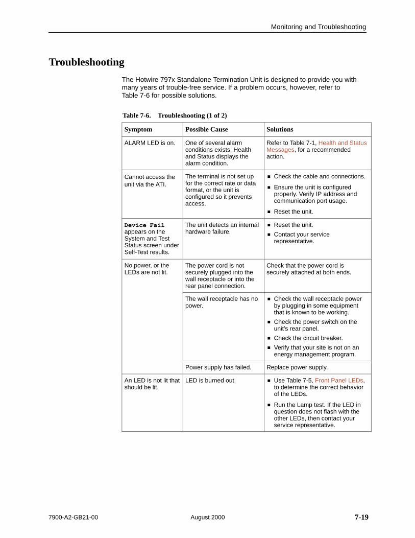
Monitoring and Troubleshooting
7-197900-A2-GB21-00 August 2000
Troubleshooting
The Hotwire 797x Standalone Termination Unit is designed to provide you withmany years of trouble-free service. If a problem occurs, however, refer to Table 7-6 for possible solutions.
Table 7-6. Troubleshooting (1 of 2)
Symptom Possible Cause Solutions
ALARM LED is on. One of several alarmconditions exists. Healthand Status displays thealarm condition.
Refer to Table 7-1, Health and StatusMessages, for a recommendedaction.
Cannot access theunit via the ATI.
The terminal is not set upfor the correct rate or dataformat, or the unit isconfigured so it preventsaccess.
Check the cable and connections.
Ensure the unit is configuredproperly. Verify IP address andcommunication port usage.
Reset the unit.
Device Failappears on theSystem and TestStatus screen underSelf-Test results.
The unit detects an internalhardware failure.
Reset the unit.
Contact your servicerepresentative.
No power, or theLEDs are not lit.
The power cord is notsecurely plugged into thewall receptacle or into therear panel connection.
Check that the power cord issecurely attached at both ends.
The wall receptacle has nopower.
Check the wall receptacle powerby plugging in some equipmentthat is known to be working.
Check the power switch on theunit’s rear panel.
Check the circuit breaker.
Verify that your site is not on anenergy management program.
Power supply has failed. Replace power supply.
An LED is not lit thatshould be lit.
LED is burned out. Use Table 7-5, Front Panel LEDs,to determine the correct behaviorof the LEDs.
Run the Lamp test. If the LED inquestion does not flash with theother LEDs, then contact yourservice representative.

Monitoring and Troubleshooting
7-20 7900-A2-GB21-00August 2000
Table 7-6. Troubleshooting (2 of 2)
Symptom SolutionsPossible Cause
Not receiving data. The network or data portcables are notconnected (check frontpanel LEDs for moreinformation).
A test is being executedon the unit (check theTEST LED on the front
Check network and data portcables.
Run loopback tests. Refer toChapter 8, Testing.
Stop the test or wait for the test toend.
TEST LED on the frontpanel).
The far-end unit isoffline.
The far-end unit isrunning a test.
An alarm condition existsin the far-end unit.
Make sure the far-end device ison.
Stop the far-end test.
Check the far-end Health andStatus messages.
Power-On Self-Testfails. Only POWERand ALARM LEDsare on afterpower-on.
The unit has detected aninternal hardware failure.
Reset the unit and try again.
Contact your servicerepresentative.
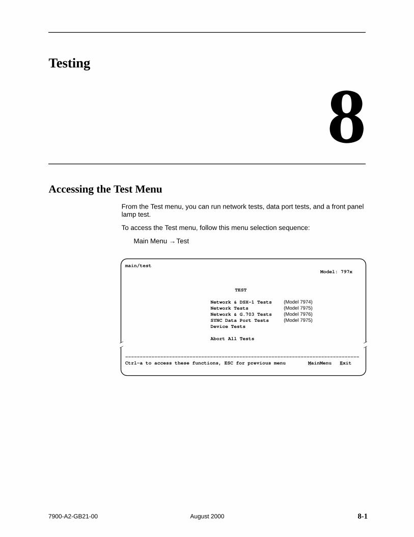
8-17900-A2-GB21-00 August 2000
Testing
8Accessing the Test Menu
From the Test menu, you can run network tests, data port tests, and a front panellamp test.
To access the Test menu, follow this menu selection sequence:
Main Menu →Test
ÎÎ
ÎÎÎÎ
main/test Model: 797x
TEST
Network & DSX-1 Tests (Model 7974)Network Tests (Model 7975)Network & G.703 Tests (Model 7976)SYNC Data Port Tests (Model 7975)Device Tests
Abort All Tests
––––––––––––––––––––––––––––––––––––––––––––––––––––––––––––––––––––––––––––––––Ctrl-a to access these functions, ESC for previous menu MainMenu Exit
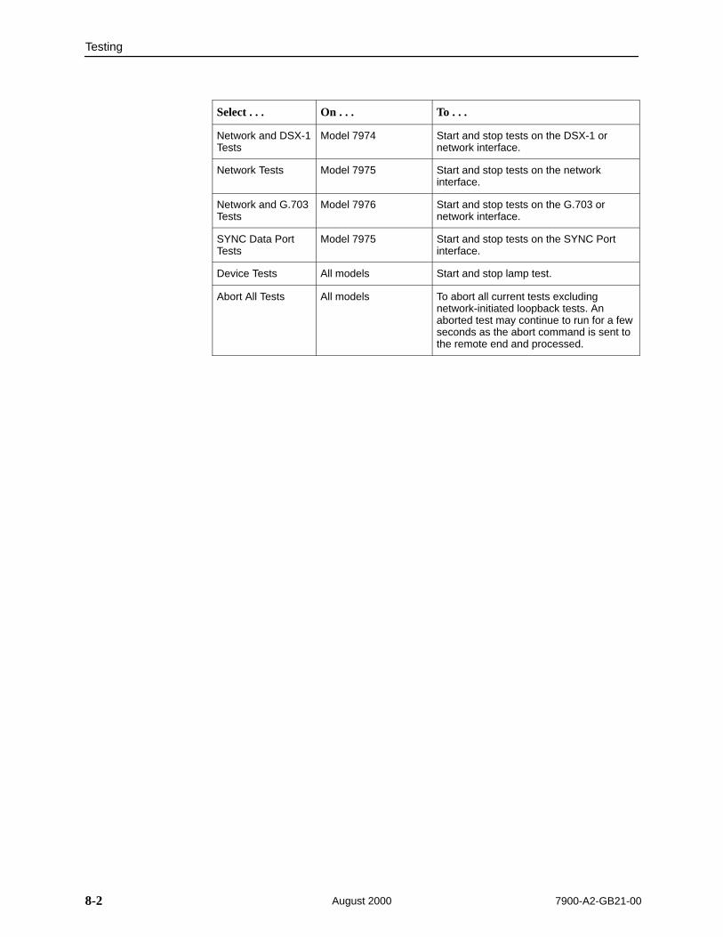
Testing
8-2 7900-A2-GB21-00August 2000
Select . . . On . . . To . . .
Network and DSX-1Tests
Model 7974 Start and stop tests on the DSX-1 ornetwork interface.
Network Tests Model 7975 Start and stop tests on the networkinterface.
Network and G.703Tests
Model 7976 Start and stop tests on the G.703 ornetwork interface.
SYNC Data PortTests
Model 7975 Start and stop tests on the SYNC Portinterface.
Device Tests All models Start and stop lamp test.
Abort All Tests All models To abort all current tests excludingnetwork-initiated loopback tests. Anaborted test may continue to run for a fewseconds as the abort command is sent tothe remote end and processed.

Testing
8-37900-A2-GB21-00 August 2000
Running Network Tests
Network tests require the participation of your network service provider. Toaccess the Network Tests screen, follow this menu selection sequence:
Model 7974 (sample screen in DSX-1 Tests on page 8-6):Main Menu →Test →Network & DSX-1 Tests
Model 7975 (sample screen below):Main Menu →Test →Network Tests
Model 7976 (sample screen in G.703 Tests on page 8-13):Main Menu →Test →Network & G.703 Tests
ÎÎÎÎÎÎÎÎÎÎÎÎÎÎÎÎÎÎÎÎÎÎÎÎÎÎÎÎÎÎÎÎÎÎÎÎÎÎÎÎÎÎÎÎÎÎÎÎÎÎÎÎÎÎÎÎÎÎÎÎÎÎÎÎÎÎÎÎÎÎÎÎÎÎÎÎÎÎÎÎÎÎÎÎÎÎÎÎÎÎÎÎÎÎÎÎÎÎÎÎÎÎÎÎÎÎÎÎÎÎÎÎÎÎÎÎÎÎÎÎÎÎÎÎÎÎÎÎÎÎÎÎÎÎÎÎÎÎÎÎÎÎÎÎÎÎÎÎÎÎÎÎÎÎÎÎÎÎÎÎÎÎÎÎÎÎÎÎÎÎÎÎÎÎÎÎÎÎÎÎÎÎÎÎÎÎÎÎÎÎÎÎÎÎÎÎÎÎÎÎÎÎÎÎÎÎÎÎÎÎÎÎÎÎÎÎÎÎÎÎÎÎÎÎÎÎÎÎÎÎÎÎÎÎÎÎÎÎÎÎÎÎÎÎÎÎÎÎÎÎÎÎÎÎÎÎÎÎÎÎÎÎÎÎÎÎÎÎÎÎÎÎÎÎÎÎÎÎÎÎÎÎÎÎÎÎÎÎÎÎÎÎÎÎÎÎÎÎÎÎÎÎÎÎÎÎÎÎÎÎÎÎÎÎÎÎÎÎÎÎÎÎÎÎÎÎÎÎÎÎÎÎÎÎÎÎÎÎÎÎÎÎÎÎÎÎÎÎÎÎÎÎÎÎÎÎÎÎÎÎÎÎÎÎÎÎÎÎÎÎÎÎÎÎÎÎÎÎÎÎÎÎÎÎÎÎÎÎÎÎÎÎÎÎÎÎÎÎÎÎ
main/test/data Model: 7975
SYNC DATA PORT TESTS
Test Command Status Results ––––––––––––––––––––––––––––––––––––––––––––––––––––––––––––––––––––––––––––––––Local Loopbacks Data Terminal Loopback: Start Inactive 00:00:00 Data Channel Loopback: Start Inactive 00:00:00
Remote Loopbacks Send Remote DCLB: Down Send Inactive 00:00:00
Network Pattern Tests Send and Monitor 511 Stop Active hh:mm:ss - Errors 99999+
––––––––––––––––––––––––––––––––––––––––––––––––––––––––––––––––––––––––––––––––Ctrl-a to access these functions, ESC for previous menu MainMenu ExitResetMon
Use the Command column to start or stop a test. When the Status columnshows that a test is Inactive, Start is displayed; when a test is Active, Stop isdisplayed. Position the cursor at the desired Start or Stop command and pressEnter.
The Results column displays the test duration.
Send and Monitor 511 is displayed on the screens but is not available in thisrelease. When Send and Monitor 511 is enabled, ResetMon will be available toreset the error counter to zero.
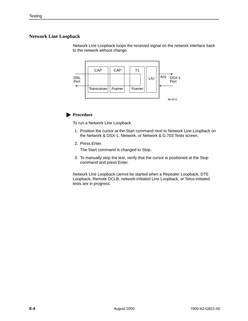
Testing
8-4 7900-A2-GB21-00August 2000
Network Line Loopback
Network Line Loopback loops the received signal on the network interface backto the network without change.
CAP
DSLPort
DSX-1Port
CAP T1
LIU
FramerFramerTransceiver
AIS
98-16112
Procedure
To run a Network Line Loopback:
1. Position the cursor at the Start command next to Network Line Loopback onthe Network & DSX-1, Network, or Network & G.703 Tests screen.
2. Press Enter.
The Start command is changed to Stop.
3. To manually stop the test, verify that the cursor is positioned at the Stopcommand and press Enter.
Network Line Loopback cannot be started when a Repeater Loopback, DTELoopback, Remote DCLB, network-initiated Line Loopback, or Telco-initiatedtests are in progress.

Testing
8-57900-A2-GB21-00 August 2000
Remote Network Send Line Loopback
The local unit initiates this test by sending a line loopback Up or Down commandto the remote unit for 10 seconds. When the remote unit detects the loopback Upcommand, it puts itself in line loopback and lights the front panel test LED. Theremote unit remains in loopback until it receives a loopback Down command orthe remote unit’s test timeout value is exceeded. The send line loopback testsboth units. External equipment can be used to verify the link.
CAP
DSX-1Port
CAP T1
LIU
FramerFramerTransceiver
98-16109
CAPCAPT1
LIU
Framer Framer Transceiver
AIS
Local Remote
Procedure
To run a Remote Network Send Line Loopback:
1. Position the cursor at the Up or Down selection next to Send Line Loopbackon the Network & DSX-1, Network, or Network & G.703 Tests screen.
2. Press the spacebar to select either Up or Down.
3. Position the cursor at the Send command next to Up or Down selection.
4. Press Enter.
The local unit stops sending the loopback command automatically after 10 seconds. You cannot stop the Send Line Loopback test manually.
The Remote Network Send Line Loopback cannot be started when any otherloopback test is active on the network interface.

Testing
8-6 7900-A2-GB21-00August 2000
DSX-1 Tests (Model 7974)
To access the Network & DSX-1 Tests screen, follow this menu selectionsequence:
Main Menu →Test →Network & DSX-1 Tests
ÎÎÎÎÎÎÎÎÎÎÎÎÎÎÎÎÎÎÎÎÎÎÎÎÎÎÎÎÎÎÎÎÎÎÎÎÎÎÎÎÎÎÎÎÎÎÎÎÎÎÎÎÎÎÎÎÎÎÎÎÎÎÎÎÎÎÎÎÎÎÎÎÎÎÎÎÎÎÎÎÎÎÎÎÎÎÎÎÎÎÎÎÎÎÎÎÎÎÎÎÎÎÎÎÎÎÎÎÎÎÎÎÎÎÎÎÎÎÎÎÎÎÎÎÎÎÎÎÎÎÎÎÎÎÎÎÎÎÎÎÎÎÎÎÎÎÎÎÎÎÎÎÎÎÎÎÎÎÎÎÎÎÎÎÎÎÎÎÎÎÎÎÎÎÎÎÎÎÎÎÎÎÎÎÎÎÎÎÎÎÎÎÎÎÎÎÎÎÎÎÎÎÎÎÎÎÎÎÎÎÎÎÎÎÎÎÎÎÎÎÎÎÎÎÎÎÎÎÎÎÎÎÎÎÎÎÎÎÎÎÎÎÎÎÎÎÎÎÎÎÎÎÎÎÎÎÎÎÎÎÎÎÎÎÎÎÎÎÎÎÎÎÎÎÎÎÎÎÎÎÎÎÎÎÎÎÎÎÎÎÎÎÎÎÎÎÎÎÎÎÎÎÎÎÎÎÎÎÎÎÎÎÎÎÎÎÎÎÎÎÎÎÎÎÎÎÎÎÎÎÎÎÎÎÎÎÎÎÎÎÎÎÎÎÎÎÎÎÎÎÎÎÎÎÎÎÎÎÎÎÎÎÎÎÎÎÎÎÎÎÎÎÎÎÎÎÎÎÎÎÎÎÎÎÎÎÎÎÎÎÎÎÎÎÎÎÎÎÎÎ
main/test/network_DSX-1 Model: 7974
NETWORK & DSX-1 TESTS
Test Command Status Results ––––––––––––––––––––––––––––––––––––––––––––––––––––––––––––––––––––––––––––––––Local Loopbacks Network Line Loopback: Start Inactive 00:00:00 Network Repeater Loopback: Start Inactive 00:00:00 DSX-1 DTE Loopback: Start Inactive 00:00:00
Remote Network Loopbacks Send Line Loopback: Down Send Inactive 00:00:00
Network Pattern Tests Send and Monitor 511 Stop Active hh:mm:ss - Errors 99999+
––––––––––––––––––––––––––––––––––––––––––––––––––––––––––––––––––––––––––––––––Ctrl-a to access these functions, ESC for previous menu MainMenu Exit ResetMon
Use the Command column to start or stop a test. When the Status columnshows that a test is Inactive, Start is displayed; when a test is Active, Stop isdisplayed. Position the cursor at the desired Start or Stop command and pressEnter.
The Results column displays the test duration.

Testing
8-77900-A2-GB21-00 August 2000
Network Repeater Loopback (DSX-1)
Network Repeater Loopback loops the signal being sent from the data port backto the data port and to the network interface.
Activating the Network Repeater Loopback test causes the EmbeddedOperations Channel (EOC), used for management, to be lost to the remote unit.
CAP
DSLPort
DSX-1Port
CAP T1
LIU
FramerFramerTransceiver
98-16111
Procedure
To run a DSX-1 Network Repeater Loopback:
1. Position the cursor at the Start command next to Network RepeaterLoopback on the Network & DSX-1 Tests screen.
2. Press Enter.
The Start command is changed to Stop.
3. To manually stop the test, verify that the cursor is positioned at the Stopcommand and press Enter.
A DSX-1 Network Repeater Loopback cannot be started when any otherLoopback test is in progress.

Testing
8-8 7900-A2-GB21-00August 2000
DSX-1 DTE Loopback
DSX-1 DTE Loopback loops the DSX-1 signal back to itself before the signal issent to the Framer.
CAP
DSLPort
DSX-1Port
CAP T1
LIU
FramerFramerTransceiver
98-16110
All Ones
Procedure
To run a DSX-1 DTE Loopback:
1. Position the cursor at the Start command next to DSX-1 DTE Loopback onthe Network & DSX-1 Tests screen.
2. Press Enter.
The Start command is changed to Stop.
3. To manually stop the test, verify that the cursor is positioned at the Stopcommand and press Enter.
A DSX-1 DTE Loopback cannot be started when any other loopback test is inprogress.
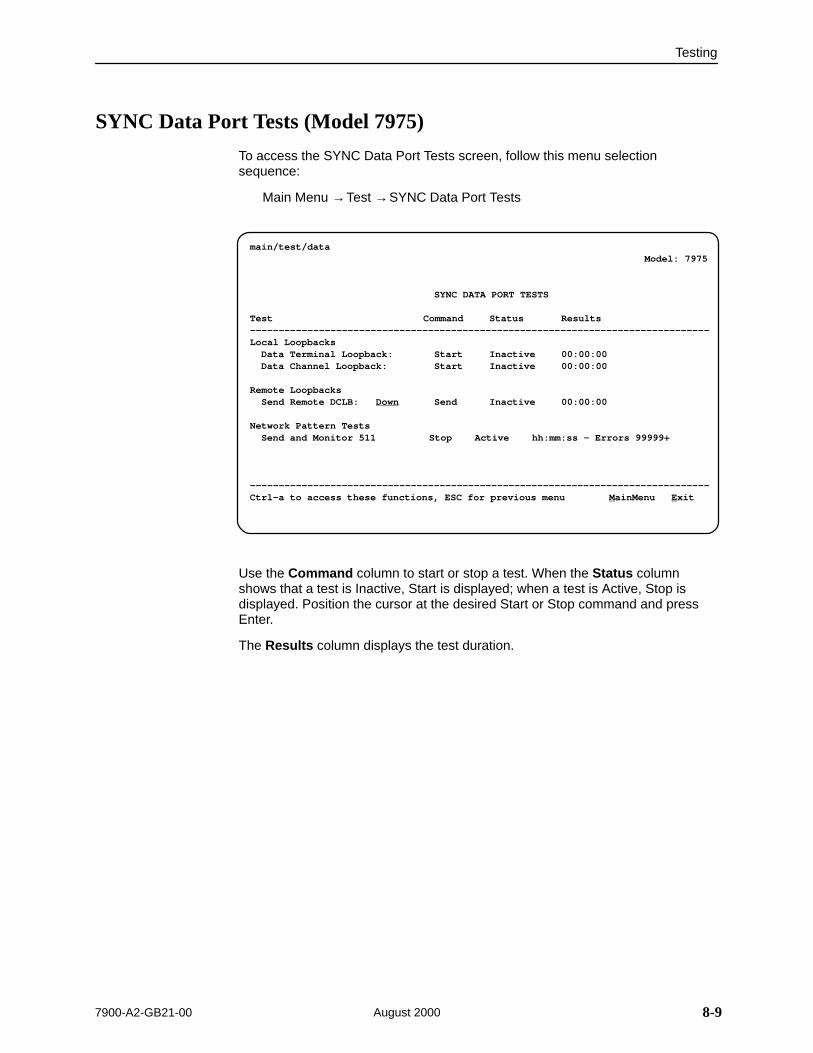
Testing
8-97900-A2-GB21-00 August 2000
SYNC Data Port Tests (Model 7975)
To access the SYNC Data Port Tests screen, follow this menu selectionsequence:
Main Menu →Test →SYNC Data Port Tests
ÎÎÎÎÎÎÎÎÎÎÎÎÎÎÎÎÎÎÎÎÎÎÎÎÎÎÎÎÎÎÎÎÎÎÎÎÎÎÎÎÎÎÎÎÎÎÎÎÎÎÎÎÎÎÎÎÎÎÎÎÎÎÎÎÎÎÎÎÎÎÎÎÎÎÎÎÎÎÎÎÎÎÎÎÎÎÎÎÎÎÎÎÎÎÎÎÎÎÎÎÎÎÎÎÎÎÎÎÎÎÎÎÎÎÎÎÎÎÎÎÎÎÎÎÎÎÎÎÎÎÎÎÎÎÎÎÎÎÎÎÎÎÎÎÎÎÎÎÎÎÎÎÎÎÎÎÎÎÎÎÎÎÎÎÎÎÎÎÎÎÎÎÎÎÎÎÎÎÎÎÎÎÎÎÎÎÎÎÎÎÎÎÎÎÎÎÎÎÎÎÎÎÎÎÎÎÎÎÎÎÎÎÎÎÎÎÎÎÎÎÎÎÎÎÎÎÎÎÎÎÎÎÎÎÎÎÎÎÎÎÎÎÎÎÎÎÎÎÎÎÎÎÎÎÎÎÎÎÎÎÎÎÎÎÎÎÎÎÎÎÎÎÎÎÎÎÎÎÎÎÎÎÎÎÎÎÎÎÎÎÎÎÎÎÎÎÎÎÎÎÎÎÎÎÎÎÎÎÎÎÎÎÎÎÎÎÎÎÎÎÎÎÎÎÎÎÎÎÎÎÎÎÎÎÎÎÎÎÎÎÎÎÎÎÎÎÎÎÎÎÎÎÎÎÎÎÎÎÎÎÎÎÎÎÎÎÎÎÎÎÎÎÎÎÎÎÎÎÎÎÎÎÎÎÎÎÎÎÎÎÎÎÎÎÎÎÎÎÎÎ
main/test/data Model: 7975
SYNC DATA PORT TESTS
Test Command Status Results ––––––––––––––––––––––––––––––––––––––––––––––––––––––––––––––––––––––––––––––––Local Loopbacks Data Terminal Loopback: Start Inactive 00:00:00 Data Channel Loopback: Start Inactive 00:00:00
Remote Loopbacks Send Remote DCLB: Down Send Inactive 00:00:00
Network Pattern Tests Send and Monitor 511 Stop Active hh:mm:ss - Errors 99999+
––––––––––––––––––––––––––––––––––––––––––––––––––––––––––––––––––––––––––––––––Ctrl-a to access these functions, ESC for previous menu MainMenu Exit
Use the Command column to start or stop a test. When the Status columnshows that a test is Inactive, Start is displayed; when a test is Active, Stop isdisplayed. Position the cursor at the desired Start or Stop command and pressEnter.
The Results column displays the test duration.

Testing
8-10 7900-A2-GB21-00August 2000
Data Terminal Loopback
Data Terminal Loopback (DTLB) loops the user data back to the DTE. Thisloopback is located as closely as possible to the user data port (DTE) interface.
98-15933-01
NTU/LTU
DSLPort
PortInterface
Framer EIA-530Port
CAPAll Ones
Procedure
To run a Data Terminal Loopback:
1. Position the cursor at the Start command next to Data Terminal Loopback onthe SYNC Data Port Tests screen.
2. Press Enter.
The Start command is changed to Stop.
3. To manually stop the test, verify that the cursor is positioned at the Stopcommand and press Enter.
Data Terminal Loopback cannot be started when a Repeater Loopback, DCLB, orRemote DCLB is already active on the data port.
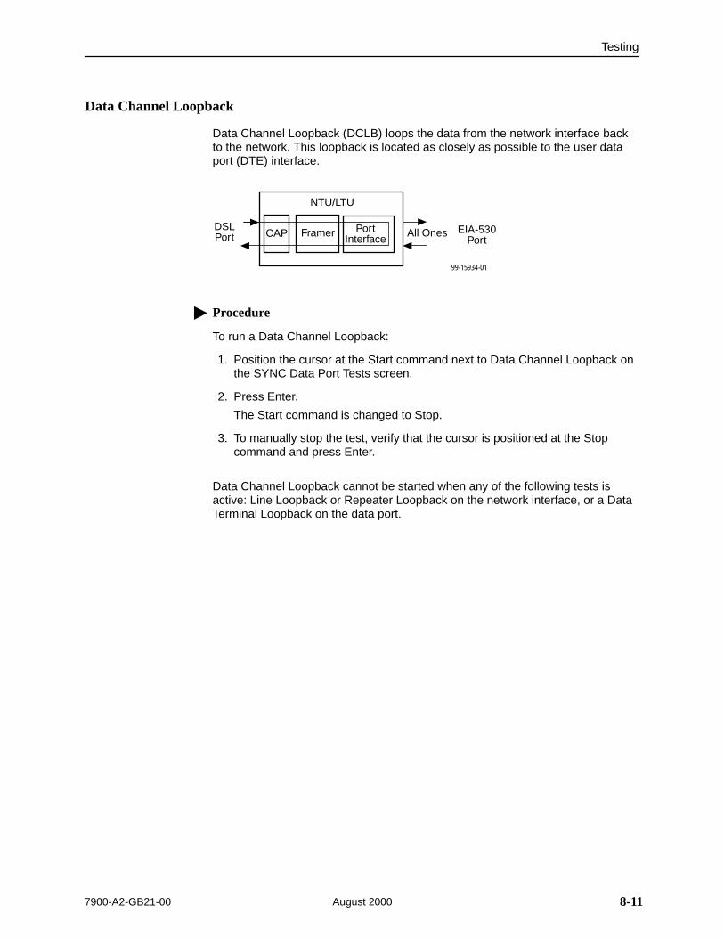
Testing
8-117900-A2-GB21-00 August 2000
Data Channel Loopback
Data Channel Loopback (DCLB) loops the data from the network interface backto the network. This loopback is located as closely as possible to the user dataport (DTE) interface.
99-15934-01
NTU/LTU
DSLPort
PortInterface
Framer EIA-530Port
CAP All Ones
Procedure
To run a Data Channel Loopback:
1. Position the cursor at the Start command next to Data Channel Loopback onthe SYNC Data Port Tests screen.
2. Press Enter.
The Start command is changed to Stop.
3. To manually stop the test, verify that the cursor is positioned at the Stopcommand and press Enter.
Data Channel Loopback cannot be started when any of the following tests isactive: Line Loopback or Repeater Loopback on the network interface, or a DataTerminal Loopback on the data port.
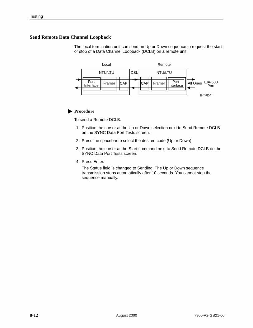
Testing
8-12 7900-A2-GB21-00August 2000
Send Remote Data Channel Loopback
The local termination unit can send an Up or Down sequence to request the startor stop of a Data Channel Loopback (DCLB) on a remote unit.
99-15935-01
NTU/LTU
PortInterface
Framer EIA-530Port
CAP All Ones
NTU/LTU
PortInterface
Framer CAP
Local Remote
DSL
Procedure
To send a Remote DCLB:
1. Position the cursor at the Up or Down selection next to Send Remote DCLBon the SYNC Data Port Tests screen.
2. Press the spacebar to select the desired code (Up or Down).
3. Position the cursor at the Start command next to Send Remote DCLB on theSYNC Data Port Tests screen.
4. Press Enter.
The Status field is changed to Sending. The Up or Down sequencetransmission stops automatically after 10 seconds. You cannot stop thesequence manually.

Testing
8-137900-A2-GB21-00 August 2000
G.703 Tests (Model 7976)
To access the Network & G.703 Tests screen, follow this menu selectionsequence:
Main Menu →Test →Network & G.703 Tests
ÎÎÎÎÎÎÎÎÎÎÎÎÎÎÎÎÎÎÎÎÎÎÎÎÎÎÎÎÎÎÎÎÎÎÎÎÎÎÎÎÎÎÎÎÎÎÎÎÎÎÎÎÎÎÎÎÎÎÎÎÎÎÎÎÎÎÎÎÎÎÎÎÎÎÎÎÎÎÎÎÎÎÎÎÎÎÎÎÎÎÎÎÎÎÎÎÎÎÎÎÎÎÎÎÎÎÎÎÎÎÎÎÎÎÎÎÎÎÎÎÎÎÎÎÎÎÎÎÎÎÎÎÎÎÎÎÎÎÎÎÎÎÎÎÎÎÎÎÎÎÎÎÎÎÎÎÎÎÎÎÎÎÎÎÎÎÎÎÎÎÎÎÎÎÎÎÎÎÎÎÎÎÎÎÎÎÎÎÎÎÎÎÎÎÎÎÎÎÎÎÎÎÎÎÎÎÎÎÎÎÎÎÎÎÎÎÎÎÎÎÎÎÎÎÎÎÎÎÎÎÎÎÎÎÎÎÎÎÎÎÎÎÎÎÎÎÎÎÎÎÎÎÎÎÎÎÎÎÎÎÎÎÎÎÎÎÎÎÎÎÎÎÎÎÎÎÎÎÎÎÎÎÎÎÎÎÎÎÎÎÎÎÎÎÎÎÎÎÎÎÎÎÎÎÎÎÎÎÎÎÎÎÎÎÎÎÎÎÎÎÎÎÎÎÎÎÎÎÎÎÎÎÎÎÎÎÎÎÎÎÎÎÎÎÎÎÎÎÎÎÎÎÎÎÎÎÎÎÎÎÎÎÎÎÎÎÎÎÎÎÎÎÎÎÎÎÎÎÎÎÎÎÎÎÎÎÎÎÎÎÎÎÎÎÎÎÎÎÎÎ
main/test/network_G.703
Model: 7976
NETWORK & G.703 TESTS
Test Command Status Results ––––––––––––––––––––––––––––––––––––––––––––––––––––––––––––––––––––––––––––––––Local Loopbacks Network Line Loopback: Start Inactive 00:00:00 Network Repeater Loopback: Start Inactive 00:00:00 G.703 DTE Loopback: Start Inactive 00:00:00
Remote Loopbacks Send Line Loopback: Down Send Inactive 00:00:00
Pattern Tests Send and Monitor 511 Stop Active hh:mm:ss - Errors 99999+
––––––––––––––––––––––––––––––––––––––––––––––––––––––––––––––––––––––––––––––––Ctrl-a to access these functions, ESC for previous menu MainMenu Exit ResetMon
Use the Command column to start or stop a test. When the Status columnshows that a test is Inactive, Start is displayed; when a test is Active, Stop isdisplayed. Position the cursor at the desired Start or Stop command and pressEnter.
The Results column displays the test duration.
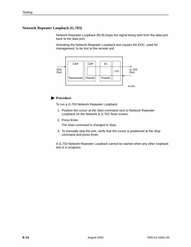
Testing
8-14 7900-A2-GB21-00August 2000
Network Repeater Loopback (G.703)
Network Repeater Loopback (RLB) loops the signal being sent from the data portback to the data port.
Activating the Network Repeater Loopback test causes the EOC, used formanagement, to be lost to the remote unit.
CAP
DSLPort
G.703Port
CAP E1
LIU
FramerFramerTransceiver
00-16825
Procedure
To run a G.703 Network Repeater Loopback:
1. Position the cursor at the Start command next to Network RepeaterLoopback on the Network & G.703 Tests screen.
2. Press Enter.
The Start command is changed to Stop.
3. To manually stop the test, verify that the cursor is positioned at the Stopcommand and press Enter.
A G.703 Network Repeater Loopback cannot be started when any other loopbacktest is in progress.
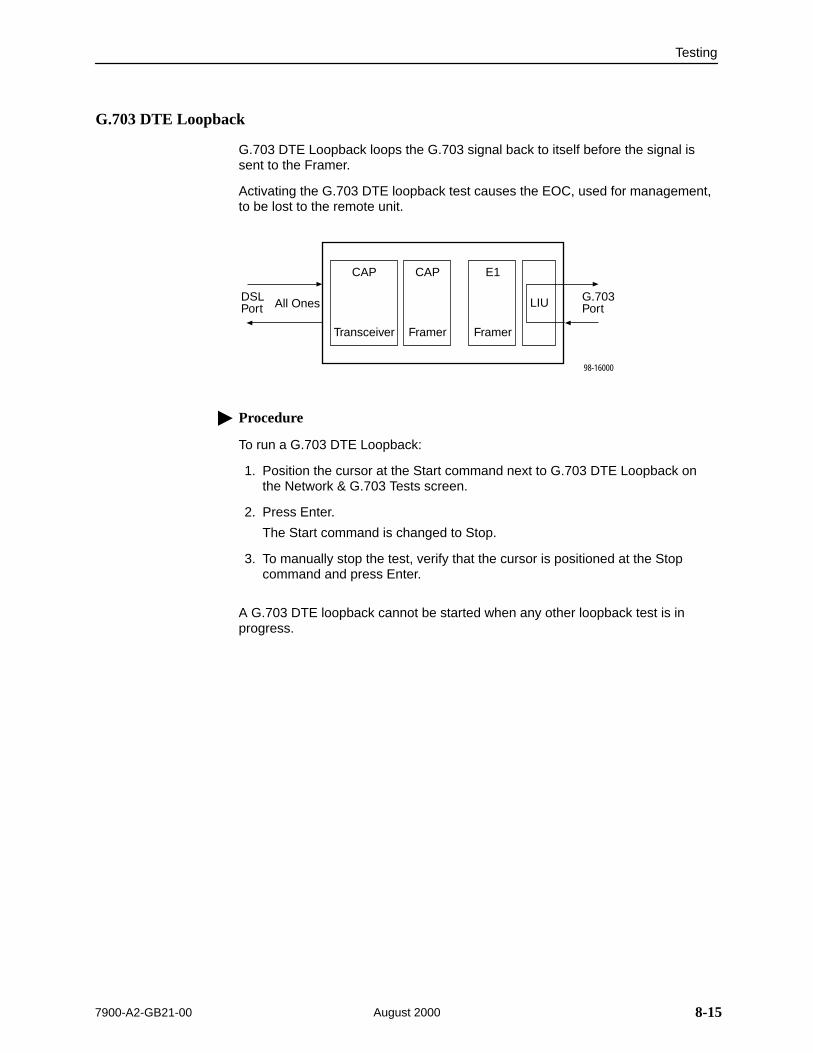
Testing
8-157900-A2-GB21-00 August 2000
G.703 DTE Loopback
G.703 DTE Loopback loops the G.703 signal back to itself before the signal issent to the Framer.
Activating the G.703 DTE loopback test causes the EOC, used for management,to be lost to the remote unit.
CAP
DSLPort
G.703Port
CAP E1
LIU
FramerFramerTransceiver
98-16000
All Ones
Procedure
To run a G.703 DTE Loopback:
1. Position the cursor at the Start command next to G.703 DTE Loopback onthe Network & G.703 Tests screen.
2. Press Enter.
The Start command is changed to Stop.
3. To manually stop the test, verify that the cursor is positioned at the Stopcommand and press Enter.
A G.703 DTE loopback cannot be started when any other loopback test is inprogress.

Testing
8-16 7900-A2-GB21-00August 2000
Device Tests
The Device Tests branch is used to access the only card-level test, the LampTest. To access the Device Tests screen, follow this menu selection sequence:
Main Menu →Test →Device Tests
main/test/card Model: 797x
DEVICE TESTS
Test Command Status––––––––––––––––––––––––––––––––––––––––––––––––––––––––––––––––––––––––––––––––
Lamp Test: Start Inactive
––––––––––––––––––––––––––––––––––––––––––––––––––––––––––––––––––––––––––––––––Ctrl-a to access these functions, ESC for previous menu MainMenu Exit
Î ÎÎ
Lamp Test
The Lamp Test determines whether all LEDs are lighting and functioning properly.
Procedure
To test the LEDs:
1. Position the cursor at the Start command next to Lamp Test on the DeviceTests screen.
2. Press Enter.
The Start command is changed to Stop. During the Lamp Test, all LEDs blinksimultaneously every second. When you stop the Lamp Test, the LEDs arerestored to their normal condition.
3. To stop the Lamp Test, position the cursor at the Stop command and pressEnter.
Testing
8-177900-A2-GB21-00 August 2000
Ending an Active Test
A test initiated by the user can be ended using:
The Test Timeout option to automatically terminate a Loopback or Patterntest (as opposed to manually terminating a test) after it has been running aspecified period of time. The default is 10 minutes. Refer to Table A-7,System Options.
The Command column on each test screen. To manually stop the test, pressEnter when the cursor is on the Stop command.
The Abort Tests selection from the Test menu to stop all tests running on allinterfaces, with the exception of network-initiated loopbacks. CommandComplete appears when all tests on all interfaces have been terminated.
An aborted test may continue to run for a few seconds as the abort commandis sent to the remote end and processed.

Testing
8-18 7900-A2-GB21-00August 2000
Telco-Initiated Tests (Model 7974)
The Hotwire 7974 Standalone Termination Unit supports Telco-initiated tests asshown in the following table.
Activation andDeactivation Line Loopback Payload Loopback
Remote LineLoopback
In-Band Signal Supported Not Applicable Supported
Bit-Oriented Supported Supported Supported
Message-Oriented Not Applicable Not Supported Not Applicable
Telco-Initiated Line Loopback
The Hotwire 7974 Standalone Termination Unit supports line loopback asspecified in AT&T TR 54016, AT&T TR 62411, and ANSI T1.403. A Telco-initiatedline loopback loops the received signal on the DSX-1 interface back to the DSX-1interface without modification. Framing, CRC, and FDL bits are returnedunaltered, and no BPVs or other line coding errors are removed.
CAP
DSLPort
DSX-1Port
CAP T1
LIU
FramerFramerTransceiver
99-16252
All Ones Telco

Testing
8-197900-A2-GB21-00 August 2000
Telco-Initiated Payload Loopback
The Hotwire 7974 Standalone Termination Unit supports payload loopback asspecified in AT&T TR 54016 and ANSI T1.403. A Telco-initiated payload loopbackloops the received signal on the DSX-1 interface back to the DSX-1 interface.Framing, CRC, and FDL bits are regenerated at the point of the loopback, andBPVs are removed.
CAP
DSLPort
DSX-1Port
CAP T1
LIU
FramerFramerTransceiver
99-16253
All Ones Telco
Telco-Initiated Remote Line Loopback
If Remote Telco Loopback is enabled, a Telco-initiated line loopback loopsreceived data at the remote unit and passes it back to the Telco through the localunit.
The following figure shows the data flow for a remote Telco-initiated lineloopback.
CAP
DSX-1Port
CAP T1
LIU
FramerFramerTransceiver
98-16109
CAPCAPT1
LIU
Framer Framer Transceiver
Telco
LocalRemote
DSX-1Port
AIS
DSL

Testing
8-20 7900-A2-GB21-00August 2000

A-17900-A2-GB21-00 August 2000
Configuration Options
AOverview
The tables in this appendix summarize the configuration options accessed whenyou select the Configuration option on the Main Menu. The Configuration optionsare arranged into groups based upon functionality.
Select . . . To Access the . . . To Configure the . . .
Network Network Interface Options, Table A-1 DSL network interface onthe unit.
DSX-1or
SYNC Port or
G.703
DSX-1 Interface Options, Table A-4
Synchronous Data Port Options, Table A-5
G.703 Interface Options, Table A-6
DSX-1 interface (Model 7974)
Synchronous DTE interface(Model 7975)
G.703 interface (Model 7976)
SystemOptions
System Options, Table A-7 General system options ofthe unit.
CommunicationPort
Communication Port Options, Table A-8 Unit’s COM port options.
ManagementandCommunication
Telnet Session Options, Table A-9
Communication Protocol Options, Table A-10
General SNMP ManagementOptions, Table A-11
SNMP NMS Security Options, Table A-12
SNMP Traps Options, Table A-13
Management support of theunit through SNMP andTelnet.
NOTE:All changes to configuration options must be saved. Refer to SavingConfiguration Options in Chapter 3, Initial Startup and Configuration.

Configuration Options
A-2 7900-A2-GB21-00August 2000
Network Interface Options Menu
For Network Interface Options, refer to Table A-1. To access the NetworkInterface Options screen, follow this menu selection sequence:
Main Menu →Configuration →Current Configuration → Network
ÎÎÎÎÎÎÎÎÎÎÎÎÎÎÎÎÎÎÎÎÎÎÎÎÎÎÎÎÎÎÎÎÎÎÎÎÎÎÎÎÎÎÎÎÎÎÎÎÎÎÎÎÎÎÎÎÎÎÎÎÎÎÎÎÎÎÎÎÎÎÎÎÎÎÎÎÎÎÎÎÎÎÎÎÎÎÎÎÎÎÎÎÎÎÎÎÎÎÎÎÎÎÎÎÎÎÎÎÎÎÎÎÎÎÎÎÎÎÎÎÎÎÎÎÎÎÎÎÎÎÎÎÎÎÎÎÎÎÎÎÎÎÎÎÎÎÎÎÎÎÎÎÎÎÎÎÎÎÎÎÎÎÎÎÎÎÎÎÎÎÎÎÎÎÎÎÎÎÎÎÎÎÎÎÎÎÎÎÎÎÎÎÎÎÎÎÎÎÎÎÎÎÎÎÎÎÎÎÎÎÎÎÎÎÎÎÎÎÎÎÎÎÎÎÎÎÎÎÎÎÎÎÎÎÎÎÎÎÎÎÎÎÎÎÎÎÎÎÎÎÎÎÎÎÎÎÎÎÎÎÎÎÎÎÎÎÎÎÎÎÎÎÎÎÎÎÎÎÎÎÎÎÎÎÎÎÎÎÎÎÎÎÎÎÎÎÎÎÎÎÎÎÎÎÎÎÎÎÎÎÎÎÎÎÎÎÎÎÎÎÎÎÎÎÎÎÎÎÎÎÎÎÎÎÎÎÎÎÎÎÎÎÎÎÎÎÎÎÎÎÎÎÎÎÎÎÎÎÎÎÎÎÎÎÎÎÎÎÎÎÎÎÎÎÎÎÎÎÎÎÎÎÎÎÎÎÎÎÎÎÎÎÎÎÎÎÎÎÎÎ
main/config/network Hotwire Model: 797x
NETWORK INTERFACE OPTIONS
Port Status Enable Margin Threshold: –3dbExcessive Error Rate Threshold: 1E–5AutoRate: DisableDSL Line Rate: 1552 kbpsEIA-530 Payload Rate 1536 kbpsTransmit Attenuation 0dBPeer IP Address: 111.255.255.000 Clear
Circuit Identifier: Clear
––––––––––––––––––––––––––––––––––––––––––––––––––––––––––––––––––––––––––––––––Ctrl-a to access these functions, ESC for previous menu MainMenu Exit Save
Table A-1. Network Interface Options (1 of 3)
Margin Threshold
Possible Settings: –5db, –4db, –3db, –2db, –1db, 0db, 1db, 2db, 3db, 4db, 5db, 6db,7db, 8db, 9db, 10db Default Setting: 0db
Determines the level, expressed in decibels, at which a signal-to-noise margin alarmcondition is reported.
–5db to 10db – Sets the margin threshold to this value.
Excessive Error Rate Threshold
Possible Settings: 1E–4, 1E–5, 1E–6, 1E–7, 1E–8, 1E–9Default Setting: 1E–6
Determines the error rate at which an excessive error rate (EER) condition isrecognized. The rate is the ratio of the number of CRC errors to the number of bitsreceived in a certain period.

Configuration Options
A-37900-A2-GB21-00 August 2000
Table A-1. Network Interface Options (2 of 3)
AutoRate
Possible Settings: Enable, DisableDefault Setting: Disable
Determines whether the unit automatically adjusts to the best line rate for conditions, oris fixed at the rate in the DSL Line Rate field.
AutoRate is only available when the unit is configured as an LTU.
Enable – The LTU adjusts to the best line rate. The maximum possible rate is thesetting of Max DSL AutoRate.
Disable – The LTU’s line rate is the DSL Line Rate selected.
DSL Line Rate
Possible Settings (Model 7974): 144, 272, 400, 528, 784, 1040, 1552Default Setting: 1552
Possible Settings (Model 7975): 144, 272, 400, 528, 784, 1040 (all units), 1552, 2064,2320 (2 Mbps unit only)Default Setting: 1040 (1 Mbps units) or 2320 (2 Mbps units)
Possible Settings (Model 7976): 144, 272, 400, 528, 784, 1040, 1552, 2064Default Setting: 2064
Determines the fixed line rate of the LTU when AutoRate is disabled. See Table A-2 andTable A-3 for information about maximum payload rates for different DSL line rates.
DSL Line Rate is only available when the unit is configured as an LTU.
144 to 2064 – The fixed DSL Line Rate, in kbps.
Max DSL AutoRate
Possible Settings (Model 7974): 144, 272, 400, 528, 784, 1040, 1552Default Setting: 1552
Possible Settings (Model 7975): 144, 272, 400, 528, 784, 1040 (all units), 1552, 2064,2320 (2 Mbps unit only)Default Setting: 1040 (1 Mbps units) or 2320 (2 Mbps units)
Possible Settings (Model 7976): 144, 272, 400, 528, 784, 1040, 1552, 2064Default Setting: 2064
Determines the maximum rate the unit can AutoRate to. See Table A-2 and Table A-3for information about maximum payload rates for different DSL line rates.
Max DSL AutoRate is only available when the unit is configured as an LTU andAutoRate is enabled.
144 to 2064 – The AutoRate ceiling, in kbps.
EIA-530 Payload Rate
Possible Settings: 64, 128, 512, 768, 1024, 1536, 2048Default Setting: [Highest multiple of 64 kbps supported by the DSL Line Rate]
Models 7974 and 7976. When the NTU has an EIA-530-A interface, the Payload Rateset on the LTU determines the port speed of the synchronous port of the NTU. SeeTable A-2 and Table A-3 for information about maximum payload rates for different DSLline rates.
Payload Rate is only available when the unit is configured as an LTU. A PayloadRate of 2048 is available only on Model 7976.
64 to 2048 – The Payload Rate, in kbps.
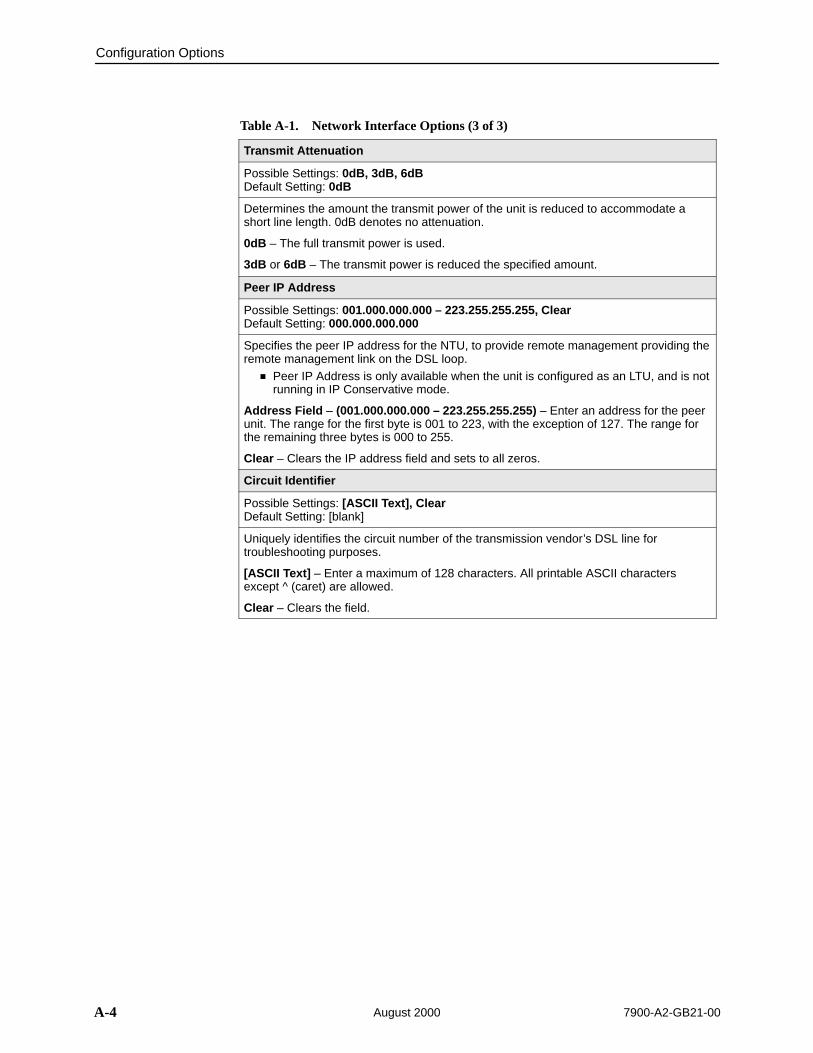
Configuration Options
A-4 7900-A2-GB21-00August 2000
Table A-1. Network Interface Options (3 of 3)
Transmit Attenuation
Possible Settings: 0dB, 3dB, 6dBDefault Setting: 0dB
Determines the amount the transmit power of the unit is reduced to accommodate ashort line length. 0dB denotes no attenuation.
0dB – The full transmit power is used.
3dB or 6dB – The transmit power is reduced the specified amount.
Peer IP Address
Possible Settings: 001.000.000.000 – 223.255.255.255, ClearDefault Setting: 000.000.000.000
Specifies the peer IP address for the NTU, to provide remote management providing theremote management link on the DSL loop.
Peer IP Address is only available when the unit is configured as an LTU, and is notrunning in IP Conservative mode.
Address Field – (001.000.000.000 – 223.255.255.255) – Enter an address for the peerunit. The range for the first byte is 001 to 223, with the exception of 127. The range forthe remaining three bytes is 000 to 255.
Clear – Clears the IP address field and sets to all zeros.
Circuit Identifier
Possible Settings: [ASCII Text], ClearDefault Setting: [blank]
Uniquely identifies the circuit number of the transmission vendor’s DSL line fortroubleshooting purposes.
[ASCII Text] – Enter a maximum of 128 characters. All printable ASCII charactersexcept ^ (caret) are allowed.
Clear – Clears the field.

Configuration Options
A-57900-A2-GB21-00 August 2000
Table A-2 and Table A-3 provides the maximum payload rates achievable foreach DSL line rate and the number of time slots required to achieve that payloadrate. For G.703, the payload rate depends on whether you are using signaling(time slots 0 and 16) or data only (time slot 0).
Table A-2. Payload Rates and DSL Line Rates for DSX-1
DSX-1-to-DSX-1 DSX-1- to-EIA-530-A
DSL LineRate (kbps)
MaximumPayload Rate(kbps) Time Slots
MaximumPayload Rate(kbps) Time Slots
1552 1536 24 1536 24
1040 960 15 1024 16
784 704 11 768 12
528 448 7 512 8
400 320 5 384 6
272 256 4 256 4
144 128 2 64, 128 1, 2
Table A-3. Payload Rates and DSL Line Rates for G.703
Voice ModeG.703-to-G.703
Data ModeG.703-to-G.703
Data ModeG.703-to-EIA-530-A
DSL LineRate (kbps)
MaximumPayload Rate(kbps)
TimeSlots
MaximumPayload Rate(kbps)
TimeSlots
MaximumPayload Rate(kbps)
Timeslots
2064 1920 30 1984 31 1984 31
1552 1408 22 1472 23 1536 24
1040 896 14 960 15 1024 16
784 640 10 704 11 768 12
528 384 6 448 7 512 8
400 256 4 320 5 384 6
272 128 2 192 3 256 4
144 N/A N/A 64 1 64, 128 1, 2

Configuration Options
A-6 7900-A2-GB21-00August 2000
DSX-1 Interface Options for Model 7974
For DSX-1 Interface Options, refer to Table A-4. To access the DSX-1 InterfaceOptions screen, follow this menu selection sequence:
Main Menu →Configuration →Load Configuration From →DSX
Î ÎÎ
main/config/DSX–1 Model: 7974
DSX–1 INTERFACE OPTIONS
Line Coding: B8BSLine Framing: ESFLine Equalization: 0-133 Excessive Error Rate Threshold: 1E-4Send (AIS) on Network Failure: Enable
Primary Clock Source: Internal
––––––––––––––––––––––––––––––––––––––––––––––––––––––––––––––––––––––––––––––––Ctrl-a to access these functions, ESC for previous menu MainMenu Exit Save
Table A-4. DSX-1 Interface Options for Model 7974 (1 of 2)
Line Coding
Possible Settings: AMI, B8ZSDefault Setting: B8ZS
Specifies the line coding format to be used by the DSX-1 interface.
AMI – Indicates the line coding format used by the DSX-1 interface is Alternate MarkInversion (AMI).
B8ZS – Indicates the line coding format used by the DSX-1 interface is B8ZS.
Line Framing
Possible Settings: ESF, D4Default Setting: ESF
Specifies the framing format to be used by the DSX-1 interface. Line Framing is only available when the unit is configured as an LTU. The NTU is
automatically configured to match the framing format used by the LTU.
ESF – ESF framing formatting is used for transmitted and received data over the DSX-1Interface.
D4 – D4 framing format is used for transmitted and received data over the DSX-1Interface.

Configuration Options
A-77900-A2-GB21-00 August 2000
Table A-4. DSX-1 Interface Options for Model 7974 (2 of 2)
Line Equalization
Possible Settings: 0–133, 133–266, 266–399, 399–533, 533–655Default Setting: 0–133
Compensates for signal distortion for a DSX-1 signal over a given distance.
0–133 feet – Provides equalization for a cable length up to 133 feet.133–266 feet – Provides equalization for a cable length up to 266 feet.266–399 feet – Provides equalization for a cable length up to 399 feet.399–533 feet – Provides equalization for a cable length up to 533 feet.533–655 feet – Provides equalization for a cable length up to 655 feet.
Excessive Error Rate Threshold
Possible Settings: 1E–4, 1E–5, 1E–6, 1E–7, 1E–8, 1E–9Default Setting: 1E–4
Determines the error rate at which an excessive error rate (EER) condition isrecognized. The rate is the ratio of the number of CRC errors to the number of bitsreceived in a certain period.
Send (AIS) on Network Failure
Possible Settings: Enable, DisableDefault Setting: Enable
Specifies the action taken on the signal transmitted to the DSX-1 interface when a validsignal cannot be recovered from the DSL network interface (LOS or conditions OOF orEER).
Enable – An Alarm Indication Signal (AIS) is sent to the DSX-1 port in the event of anLOS, OOF, or EER condition on the DSL interface.
Disable – The failed signal on the interface is passed through to the DSX-1 networkunchanged.
Primary Clock Source
Possible Settings: DSX-1, InternalDefault Setting: Internal
Specifies where the unit derives its timing from. Primary Clock Source is available only when the unit is configured as an LTU. If
DSL Line Rate is set lower than 1552 kbps, Primary Clock Source is forced toDSX-1 and cannot be changed.
Internal – The clock source is derived from the internal oscillator.
DSX-1 – The clock source is derived from the DSX-1 interface.

Configuration Options
A-8 7900-A2-GB21-00August 2000
Synchronous Data Port Options for Model 7975
For Synchronous Data Port Options, refer to Table A-5. To access theSynchronous Data Port Options screen, follow this menu selection sequence:
Main Menu →Configuration →Load Configuration From →SYNC Ports
Î ÎÎ
main/config/sync_data Model: 7975
SYNCHRONOUS DATA PORT OPTIONS
Port Type: E530A Payload Rate: 2320 Kbps Transmit Clock Source: Internal Send All Ones on Data Port Not Ready: Both Action on Network LOS Alarm: Halt Network Initiated Data Channel Loopback: Disable Port (DTE) Initiated Loopbacks: Disable Elastic Store: Enable
–––––––––––––––––––––––––––––––––––––––––––––––––––––––––––––––––––––––––––––––Ctrl–a to access these functions, ESC for previous menu MainMenu Exit
Table A-5. Synchronous Data Port Options for Model 7975 (1 of 3)
Port Type
Possible Settings: E530A, V.35, RS449, X.21Default Setting: E530A
Determines the port type for the data port.
E530A – The port is configured as an EIA-530-A compatible DCE. An EIA-530-Acompatible DTE can be connected directly to the DB25 Port connector on the rear panelof the unit.
V.35 – The port is configured as a V.35 compatible DCE. A V.35 compatible DTE can beconnected using an MS34 to DB25 adapter cable to connect to the DB25 Portconnector on the rear panel of the unit.
E530A – The port is configured as an RS449 compatible DCE. An RS449 compatibleDTE can be connected using a DB37 to DB25 adapter cable to connect to the DB25Port connector on the rear panel of the unit.
X.21 – The port is configured as an X.21 compatible DCE. An X.21 compatible DTE canbe connected using a DB15 to DB25 adapter cable to connect to the DB25 Portconnector on the rear panel of the unit.
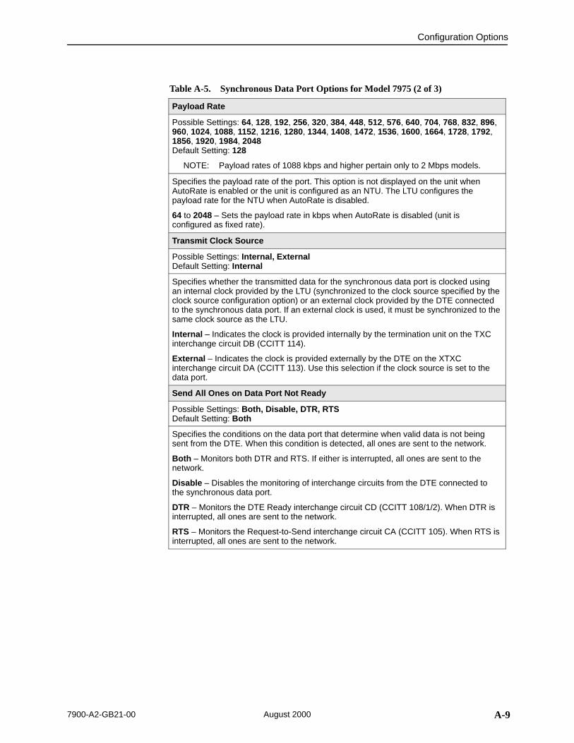
Configuration Options
A-97900-A2-GB21-00 August 2000
Table A-5. Synchronous Data Port Options for Model 7975 (2 of 3)
Payload Rate
Possible Settings: 64, 128, 192, 256, 320, 384, 448, 512, 576, 640, 704, 768, 832, 896,960, 1024, 1088, 1152, 1216, 1280, 1344, 1408, 1472, 1536, 1600, 1664, 1728, 1792,1856, 1920, 1984, 2048Default Setting: 128
NOTE: Payload rates of 1088 kbps and higher pertain only to 2 Mbps models.
Specifies the payload rate of the port. This option is not displayed on the unit whenAutoRate is enabled or the unit is configured as an NTU. The LTU configures thepayload rate for the NTU when AutoRate is disabled.
64 to 2048 – Sets the payload rate in kbps when AutoRate is disabled (unit isconfigured as fixed rate).
Transmit Clock Source
Possible Settings: Internal, ExternalDefault Setting: Internal
Specifies whether the transmitted data for the synchronous data port is clocked usingan internal clock provided by the LTU (synchronized to the clock source specified by theclock source configuration option) or an external clock provided by the DTE connectedto the synchronous data port. If an external clock is used, it must be synchronized to thesame clock source as the LTU.
Internal – Indicates the clock is provided internally by the termination unit on the TXCinterchange circuit DB (CCITT 114).
External – Indicates the clock is provided externally by the DTE on the XTXCinterchange circuit DA (CCITT 113). Use this selection if the clock source is set to thedata port.
Send All Ones on Data Port Not Ready
Possible Settings: Both, Disable, DTR, RTSDefault Setting: Both
Specifies the conditions on the data port that determine when valid data is not beingsent from the DTE. When this condition is detected, all ones are sent to the network.
Both – Monitors both DTR and RTS. If either is interrupted, all ones are sent to thenetwork.
Disable – Disables the monitoring of interchange circuits from the DTE connected tothe synchronous data port.
DTR – Monitors the DTE Ready interchange circuit CD (CCITT 108/1/2). When DTR isinterrupted, all ones are sent to the network.
RTS – Monitors the Request-to-Send interchange circuit CA (CCITT 105). When RTS isinterrupted, all ones are sent to the network.

Configuration Options
A-10 7900-A2-GB21-00August 2000
Table A-5. Synchronous Data Port Options for Model 7975 (3 of 3)
Action on Network LOS Alarm
Possible Settings: Halt, NoneDefault Setting: Halt
Specifies the action taken on the synchronous data port when an LOS (Loss Of Signal)alarm is received on the network interface.
Halt – Stops the transmission of data on the data port and disables the data port whenan LOS alarm is received on the network interface. When LOS alarms are received, allones are sent on the Received Data interchange circuit BB (CCITT 104). TheClear-to-Send interchange circuit CB (CCITT 106) is interrupted.
None – Makes the data port unaffected by LOS alarms received on the networkinterface.
Network Initiated Data Channel Loopback
Possible Settings: Disable, EnableDefault Setting: Disable
Allows the initiation and termination of a Data Channel Loopback (DCLB) by the receiptof a DCLB-actuate sequence or DCLB-release sequence from the network or far-enddevice.
Disable – Ignores the DCLB-actuate and DCLB-release sequences for this port.
Enable – DCLB-actuate and DCLB-release sequences are recognized for this port.
Port (DTE) Initiated Loopbacks
Possible Settings: Disable, DTLB, DCLB, BothDefault Setting: Disable
Allows the initiation and termination of a local Data Terminal Loopback (DTLB) orremote Data Channel Loopback (DCLB) by the DTE connected to this port. (DTLB isequivalent to a V.54 loop 3, and DCLB is equivalent to a V.54 loop 2.) Control of theseloopbacks is through the DTE interchange circuits as specified by the V.54 standard.
Disable – Disables control of local DTLBs and remote DCLBs by the DTE connected tothis port.
DTLB – Gives control of the local DTLBs for this port to the DTE attached to this port.This loopback is controlled by the Local Loopback interchange circuit LL (CCITT 141).
DCLB – Gives control of the remote DCLBs for the far-end port connected to this port tothe DTE attached to this port. This loopback is controlled by the Remote Loopbackinterchange circuit RL (CCITT 140). The far-end equipment must support in-band V.54 loopbacks.
Both – Gives control of local DTLBs and remote DCLBs to the DTE connected to thisport.
ElasticStore
Possible Settings: Disable, EnableDefault Setting: Enable
Used to enable or disable a first-in, first-out (FIFO) buffer circuit for the incomingexternal clock. This circuit is used to compensate for the differences between thefrequencies of the data clocks for the two units in the circuit. This option only applies ifthe unit is set for external timing. Do not enable Elastic Store if the attached DCE hasan elastic store buffer larger than 32 bits.
Disable – Disables the Elastic Store FIFO.
Enable – Enables the Elastic Store FIFO.

Configuration Options
A-117900-A2-GB21-00 August 2000
G.703 Interface Options for Model 7976
For G.703 Interface Options, refer to Table A-6. To access the G.703 InterfaceOptions screen, follow this menu selection sequence:
Main Menu →Configuration →Load Configuration From →G.703
Î ÎÎ
main/config/G.703 Model: 7976
G.703 INTERFACE OPTIONS
Framing: Framed Line Coding: HDB3Line Framing: noCRC4Time Slot 16: SignalingSend (AIS) on Network Failure: Enable
Primary Clock Source: G703
––––––––––––––––––––––––––––––––––––––––––––––––––––––––––––––––––––––––––––––––Ctrl-a to access these functions, ESC for previous menu MainMenu Exit Save
Table A-6. G.703 Interface Options for Model 7976 (1 of 2)
Framing
Possible Settings: Framed, UnframedDefault Setting: Framed
Specifies whether G.704 framing is used for the G.703 interface.
Framed – The unit conforms to G.704 framing.
Unframed – G.704 framing is disabled.
Line Coding
Possible Settings: AMI, HDB3Default Setting: HDB3
Specifies the line coding format to be used by the G.703 interface.
AMI – Indicates the line coding format used by the G.703 interface is Alternate MarkInversion (AMI).
HDB3 – Indicates the line coding format used by the G.703 interface is HDB3.

Configuration Options
A-12 7900-A2-GB21-00August 2000
Table A-6. G.703 Interface Options for Model 7976 (2 of 2)
Line Framing
Possible Settings: CRC4, noCRC4Default Setting: noCRC4
Specifies the framing format to be used by the G.703 interface. Line Framing is only available when the standalone unit is configured as an LTU,
AutoRate is disabled, and the DSL Line rate is 2064 kbps. Otherwise the noCRC4framing format is used. The NTU is automatically configured to match the framingformat used by the LTU.
CRC4 – CRC4 framing formatting is used for transmitted and received data over theNetwork Interface.
noCRC4 – Non-CRC4 framing format is used for transmitted and received data over theNetwork Interface.
Time Slot 16
Possible Settings: Signaling, DataDefault Setting: Signaling
Specifies whether the G.703 interface is used for voice or data.
Signaling – Time slot 16 is used for signaling (the unit is in voice mode).
Data – Time slot 16 is used for data (the unit is in data mode).
Send (AIS) on Network Failure
Possible Settings: Enable, DisableDefault Setting: Enable
Specifies the action taken on the signal transmitted to the G.703 interface when a validsignal cannot be recovered from the network interface (LOS or conditions OOF orEER).
Enable – An Alarm Indication Signal (AIS) is sent to the DTE in the event of an LOS,OOF, or EER condition on the DSL interface.
Disable – The failed signal on the interface is sent to the DTE in the event an LOS,OOF, or EER condition on the DSL interface.
Primary Clock Source
Possible Settings: G.703, InternalDefault Setting: Internal
Specifies where the unit derives its timing from.
Internal – The clock source is derived from the internal oscillator.
G.703 – The clock source is derived from the G.703 interface.

Configuration Options
A-137900-A2-GB21-00 August 2000
System Options Menu
For System Options, refer to Table A-7. To access the System Options screen,follow this menu selection sequence:
Main Menu →Configuration →Load Configuration From →System
ÎÎ
ÎÎÎÎ
main/config/system Model: 797x
SYSTEM OPTIONS
DSL Mode: NTUTest Timeout: EnableTest Duration (min): 10Telco Initiated Loopback: Enable (Model 7974)Remote Telco Line Loopback: Disable (Model 7974)G.703 Line Termination: 120 Ohm (Model 7976)
––––––––––––––––––––––––––––––––––––––––––––––––––––––––––––––––––––––––––––––––Ctrl-a to access these functions, ESC for previous menu MainMenu Exit Save
Table A-7. System Options (1 of 2)
DSL Mode
Possible Settings: LTU, NTUDefault Setting: NTU
Controls whether the unit is configured as a control unit or tributary unit.
LTU – The unit is configured as a control unit (Line Termination Unit).
NTU – The unit is configured as a tributary unit (Network Termination Unit). This unitrequests its IP address from the LTU during establishment of the PPP link.
NOTE: Changing this option resets the termination unit.
Test Timeout
Possible Settings: Enable, DisableDefault Setting: Enable
Allows tests to end automatically. The feature should be enabled when the unit isremotely managed so that control can be regained after a test is accidentally executed.
Enable – Loopback and pattern tests end when test duration is reached.
Disable – Tests run until manually terminated from the Network Tests screen orremotely (network initiated tests). Refer to Running Network Tests in Chapter 8, Testing.
Test Duration (min)
Possible Settings: 1–120Default Setting: 10
Number of minutes for a test to be active before automatically ending. Test Duration (min) appears when Test Timeout is enabled.
1 to 120 – Amount of time in minutes a test runs before terminating.

Configuration Options
A-14 7900-A2-GB21-00August 2000
Table A-7. System Options (2 of 2)
Telco Initiated Loopback (Model 7974)
Possible Settings: Enable, DisableDefault Setting: Enable
Determines if the unit responds to loopback commands on the DSX-1 interface. SeeTelco-Initiated Tests in Chapter 8, Testing.
Enable – The unit responds to loopback commands.
Disable – The unit does not respond to loopback commands.
Remote Telco Line Loopback (Model 7974)
Possible Settings: Enable, DisableDefault Setting: Disable
Determines if the unit performs a Telco-initiated loopback on just the local unit or if theloopback is performed on the remote DSL unit. See Telco-Initiated Tests in Chapter 8,Testing.
Enable – The loopback is performed on the remote unit.
Disable – The loopback is restricted to the local unit.
G.703 Line Termination (Model 7976)
Possible Settings: 75 ohms, 120 ohmsDefault Setting: 120 ohms
Specifies the impedance of the G.703 interface.
75 ohms – The G.703 interface impedance is 75 ohms.
120 ohms – The G.703 interface impedance is 120 ohms.

Configuration Options
A-157900-A2-GB21-00 August 2000
Communication Port
For Communication Port Options, refer to Table A-8. To access theCommunication Port screen, follow this menu selection sequence:
Main Menu →Configuration →Load Configuration From →CommunicationPort
When Port Use is Terminal, the following screen appears:
ÎÎÎÎÎÎÎÎÎÎÎÎÎÎÎÎÎÎÎÎÎÎÎÎÎÎÎÎÎÎÎÎÎÎÎÎÎÎÎÎÎÎÎÎÎÎÎÎÎÎÎÎÎÎÎÎÎÎÎÎÎÎÎÎÎÎÎÎÎÎÎÎÎÎÎÎÎÎÎÎÎÎÎÎÎÎÎÎÎÎÎÎÎÎÎÎÎÎÎÎÎÎÎÎÎÎÎÎÎÎÎÎÎÎÎÎÎÎÎÎÎÎÎÎÎÎÎÎÎÎÎÎÎÎÎÎÎÎÎÎÎÎÎÎÎÎÎÎÎÎÎÎÎÎÎÎÎÎÎÎÎÎÎÎÎÎÎÎÎÎÎÎÎÎÎÎÎÎÎÎÎÎÎÎÎÎÎÎÎÎÎÎÎÎÎÎÎÎÎÎÎÎÎÎÎÎÎÎÎÎÎÎÎÎÎÎÎÎÎÎÎÎÎÎÎÎÎÎÎÎÎÎÎÎÎÎÎÎÎÎÎÎÎÎÎÎÎÎÎÎÎÎÎÎÎÎÎÎÎÎÎÎÎÎÎÎÎÎÎÎÎÎÎÎÎÎÎÎÎÎÎÎÎÎÎÎÎÎÎÎÎÎÎÎÎÎÎÎÎÎÎÎÎÎÎÎÎÎÎÎÎÎÎÎÎÎÎÎÎÎÎÎÎÎÎÎÎÎÎÎÎÎÎÎÎÎÎÎÎÎÎÎÎÎÎÎÎÎÎÎÎÎÎÎÎÎÎÎÎÎÎÎÎÎÎÎÎÎÎÎÎÎÎÎÎÎÎÎÎÎÎÎÎÎÎÎÎÎÎÎÎÎÎÎÎÎÎÎÎÎ
main/config/com Model: 797x
COMMUNICATION PORT OPTIONS
Port Use: TerminalPort Type: AsynchronousData Rate (Kbps): 9.6Character Length: 8Parity: NoneStop Bits: 1Ignore Control Leads: Enable
Login Required: DisablePort Access Level: AdministratorInactivity Timeout: EnableDisconnect Time (Minutes): 5
–––––––––––––––––––––––––––––––––––––––––––––––––––––––––––––––––––––––––––––––Ctrl-a to access these functions, ESC for previous menu MainMenu Exit
When Net Link is selected for Port Use, the following screen appears:
Î ÎÎ
main/config/com Model: 797x
COMMUNICATION PORT OPTIONS
Port Use: Net LinkPort Type: Synchronous Data Rate (Kbps): 9.6
–––––––––––––––––––––––––––––––––––––––––––––––––––––––––––––––––––––––––––––––Ctrl-a to access these functions, ESC for previous menu MainMenu Exit
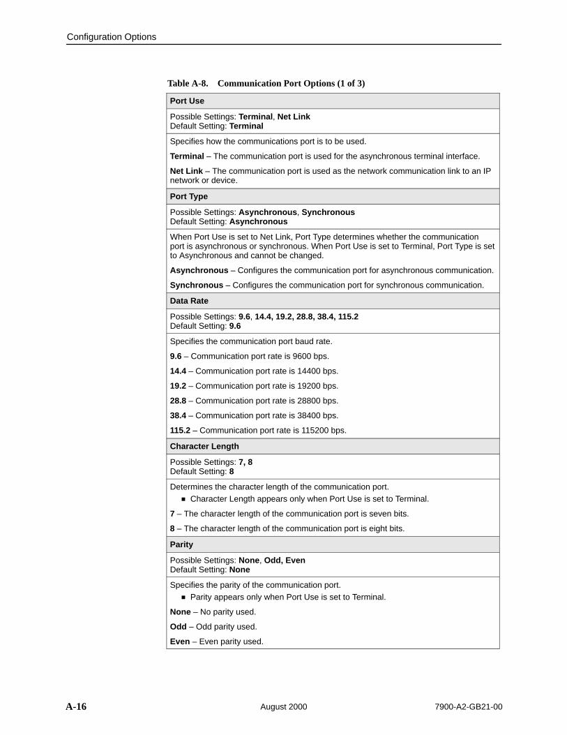
Configuration Options
A-16 7900-A2-GB21-00August 2000
Table A-8. Communication Port Options (1 of 3)
Port Use
Possible Settings: Terminal, Net LinkDefault Setting: Terminal
Specifies how the communications port is to be used.
Terminal – The communication port is used for the asynchronous terminal interface.
Net Link – The communication port is used as the network communication link to an IPnetwork or device.
Port Type
Possible Settings: Asynchronous, SynchronousDefault Setting: Asynchronous
When Port Use is set to Net Link, Port Type determines whether the communicationport is asynchronous or synchronous. When Port Use is set to Terminal, Port Type is setto Asynchronous and cannot be changed.
Asynchronous – Configures the communication port for asynchronous communication.
Synchronous – Configures the communication port for synchronous communication.
Data Rate
Possible Settings: 9.6, 14.4, 19.2, 28.8, 38.4, 115.2Default Setting: 9.6
Specifies the communication port baud rate.
9.6 – Communication port rate is 9600 bps.
14.4 – Communication port rate is 14400 bps.
19.2 – Communication port rate is 19200 bps.
28.8 – Communication port rate is 28800 bps.
38.4 – Communication port rate is 38400 bps.
115.2 – Communication port rate is 115200 bps.
Character Length
Possible Settings: 7, 8Default Setting: 8
Determines the character length of the communication port. Character Length appears only when Port Use is set to Terminal.
7 – The character length of the communication port is seven bits.
8 – The character length of the communication port is eight bits.
Parity
Possible Settings: None, Odd, EvenDefault Setting: None
Specifies the parity of the communication port. Parity appears only when Port Use is set to Terminal.
None – No parity used.
Odd – Odd parity used.
Even – Even parity used.

Configuration Options
A-177900-A2-GB21-00 August 2000
Table A-8. Communication Port Options (2 of 3)
Stop Bits
Possible Settings: 1, 1.5, 2Default Setting: 1
Specifies the number of stop bits for the communication port. Stop Bits appears only when Port Use is set to Terminal.
1 – One stop bit.
1.5 – One and one half stop bits.
2 – Two stop bits used.
Ignore Control Leads
Possible Settings: Disable, DTR Default Setting: Disable
Specifies whether DTR is used. Ignore Control Leads appears only when Port Use is set to Terminal.
Disable – Control leads are treated as standard.
DTR – DTR is ignored.
Login Required
Possible Settings: Enable, DisableDefault Setting: Disable
Specifies if an ID and password are required to access the asynchronous terminalinterface on the communication port. Login IDs are created with a password and accesslevel. Refer to Creating a Login in Chapter 6, Security.
Login Required appears only when Port Use is set to Terminal.
Enable – Login ID and password are required to access the asynchronous terminalinterface.
Disable – No Login ID and password are required to access the asynchronous terminalinterface.
Port Access Level
Possible Settings: Administrator, OperatorDefault Setting: Administrator
Specifies the highest level of access allowed when accessing an ATI session through aTelnet session.
Port Access Level appears only when Port Use is set to Terminal.
Administrator – This is the higher access level, permitting full control of the unit.Access level is determined by the Login ID. If Telnet Login Required is disabled, thesession access level is Administrator.
Operator – This is the lower access level, permitting read-only access to status andconfiguration screens.
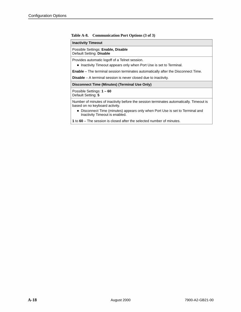
Configuration Options
A-18 7900-A2-GB21-00August 2000
Table A-8. Communication Port Options (3 of 3)
Inactivity Timeout
Possible Settings: Enable, DisableDefault Setting: Disable
Provides automatic logoff of a Telnet session. Inactivity Timeout appears only when Port Use is set to Terminal.
Enable – The terminal session terminates automatically after the Disconnect Time.
Disable – A terminal session is never closed due to inactivity.
Disconnect Time (Minutes) (Terminal Use Only)
Possible Settings: 1 – 60Default Setting: 5
Number of minutes of inactivity before the session terminates automatically. Timeout isbased on no keyboard activity.
Disconnect Time (minutes) appears only when Port Use is set to Terminal andInactivity Timeout is enabled.
1 to 60 – The session is closed after the selected number of minutes.

Configuration Options
A-197900-A2-GB21-00 August 2000
Management and Communication Options Menu
The Management and Communication Options Menu includes the following:
Telnet Session Options, Table A-9
Communication Protocol Options, Table A-10
General SNMP Management Options, Table A-11
SNMP NMS Security Options, Table A-12
SNMP Traps Options, Table A-13
Telnet Session Options
The Telnet Session configuration options control whether a Telnet session isallowed through an interconnected IP Network. If allowed, these optionsdetermine what level of security to apply to the session to control access. Onlyone Telnet session is allowed at a time. Initial values are determined by theconfiguration you currently have loaded. To access the Telnet Session Optionsscreen, follow this menu selection sequence:
Main Menu →Configuration →Load Configuration From →Management and Communication →Telnet Session
Î ÎÎ
main/config/telnet Model: 797x
TELNET SESSION OPTIONS
Telnet Session: EnableTelnet Login Required: DisableSession Access Level: AdministratorInactivity Timeout: EnableDisconnect Time (Minutes) 5
––––––––––––––––––––––––––––––––––––––––––––––––––––––––––––––––––––––––––––––––Ctrl-a to access these functions, ESC for previous menu MainMenu Exit Save
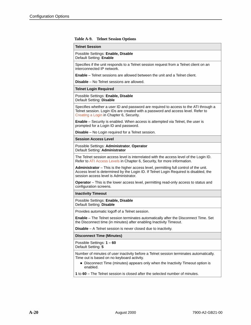
Configuration Options
A-20 7900-A2-GB21-00August 2000
Table A-9. Telnet Session Options
Telnet Session
Possible Settings: Enable, DisableDefault Setting: Enable
Specifies if the unit responds to a Telnet session request from a Telnet client on aninterconnected IP network.
Enable – Telnet sessions are allowed between the unit and a Telnet client.
Disable – No Telnet sessions are allowed.
Telnet Login Required
Possible Settings: Enable, DisableDefault Setting: Disable
Specifies whether a user ID and password are required to access to the ATI through aTelnet session. Login IDs are created with a password and access level. Refer toCreating a Login in Chapter 6, Security.
Enable – Security is enabled. When access is attempted via Telnet, the user isprompted for a Login ID and password.
Disable – No Login required for a Telnet session.
Session Access Level
Possible Settings: Administrator, OperatorDefault Setting: Administrator
The Telnet session access level is interrelated with the access level of the Login ID.Refer to ATI Access Levels in Chapter 6, Security, for more information.
Administrator – This is the higher access level, permitting full control of the unit.Access level is determined by the Login ID. If Telnet Login Required is disabled, thesession access level is Administrator.
Operator – This is the lower access level, permitting read-only access to status andconfiguration screens.
Inactivity Timeout
Possible Settings: Enable, DisableDefault Setting: Disable
Provides automatic logoff of a Telnet session.
Enable – The Telnet session terminates automatically after the Disconnect Time. Setthe Disconnect time (in minutes) after enabling Inactivity Timeout.
Disable – A Telnet session is never closed due to inactivity.
Disconnect Time (Minutes)
Possible Settings: 1 – 60Default Setting: 5
Number of minutes of user inactivity before a Telnet session terminates automatically.Time out is based on no keyboard activity.
Disconnect Time (minutes) appears only when the Inactivity Timeout option isenabled.
1 to 60 – The Telnet session is closed after the selected number of minutes.
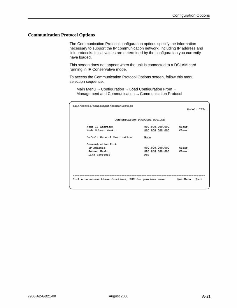
Configuration Options
A-217900-A2-GB21-00 August 2000
Communication Protocol Options
The Communication Protocol configuration options specify the informationnecessary to support the IP communication network, including IP address andlink protocols. Initial values are determined by the configuration you currentlyhave loaded.
This screen does not appear when the unit is connected to a DSLAM cardrunning in IP Conservative mode.
To access the Communication Protocol Options screen, follow this menuselection sequence:
Main Menu →Configuration →Load Configuration From →Management and Communication →Communication Protocol
ÎÎÎÎÎÎÎÎÎÎÎÎÎÎÎÎÎÎÎÎÎÎÎÎÎÎÎÎÎÎÎÎÎÎÎÎÎÎÎÎÎÎÎÎÎÎÎÎÎÎÎÎÎÎÎÎÎÎÎÎÎÎÎÎÎÎÎÎÎÎÎÎÎÎÎÎÎÎÎÎÎÎÎÎÎÎÎÎÎÎÎÎÎÎÎÎÎÎÎÎÎÎÎÎÎÎÎÎÎÎÎÎÎÎÎÎÎÎÎÎÎÎÎÎÎÎÎÎÎÎÎÎÎÎÎÎÎÎÎÎÎÎÎÎÎÎÎÎÎÎÎÎÎÎÎÎÎÎÎÎÎÎÎÎÎÎÎÎÎÎÎÎÎÎÎÎÎÎÎÎÎÎÎÎÎÎÎÎÎÎÎÎÎÎÎÎÎÎÎÎÎÎÎÎÎÎÎÎÎÎÎÎÎÎÎÎÎÎÎÎÎÎÎÎÎÎÎÎÎÎÎÎÎÎÎÎÎÎÎÎÎÎÎÎÎÎÎÎÎÎÎÎÎÎÎÎÎÎÎÎÎÎÎÎÎÎÎÎÎÎÎÎÎÎÎÎÎÎÎÎÎÎÎÎÎÎÎÎÎÎÎÎÎÎÎÎÎÎÎÎÎÎÎÎÎÎÎÎÎÎÎÎÎÎÎÎÎÎÎÎÎÎÎÎÎÎÎÎÎÎÎÎÎÎÎÎÎÎÎÎÎÎÎÎÎÎÎÎÎÎÎÎÎÎÎÎÎÎÎÎÎÎÎÎÎÎÎÎÎÎÎÎÎÎÎÎÎÎÎÎÎÎÎÎÎÎÎÎÎÎÎÎÎÎÎÎÎÎÎÎ
main/config/management/communication Model: 797x
COMMUNICATION PROTOCOL OPTIONS
Node IP Address: 000.000.000.000 Clear Node Subnet Mask: 000.000.000.000 Clear
Default Network Destination: None
Communication Port IP Address: 000.000.000.000 Clear
Subnet Mask: 000.000.000.000 Clear Link Protocol: PPP
–––––––––––––––––––––––––––––––––––––––––––––––––––––––––––––––––––––––––––––––Ctrl-a to access these functions, ESC for previous menu MainMenu Exit
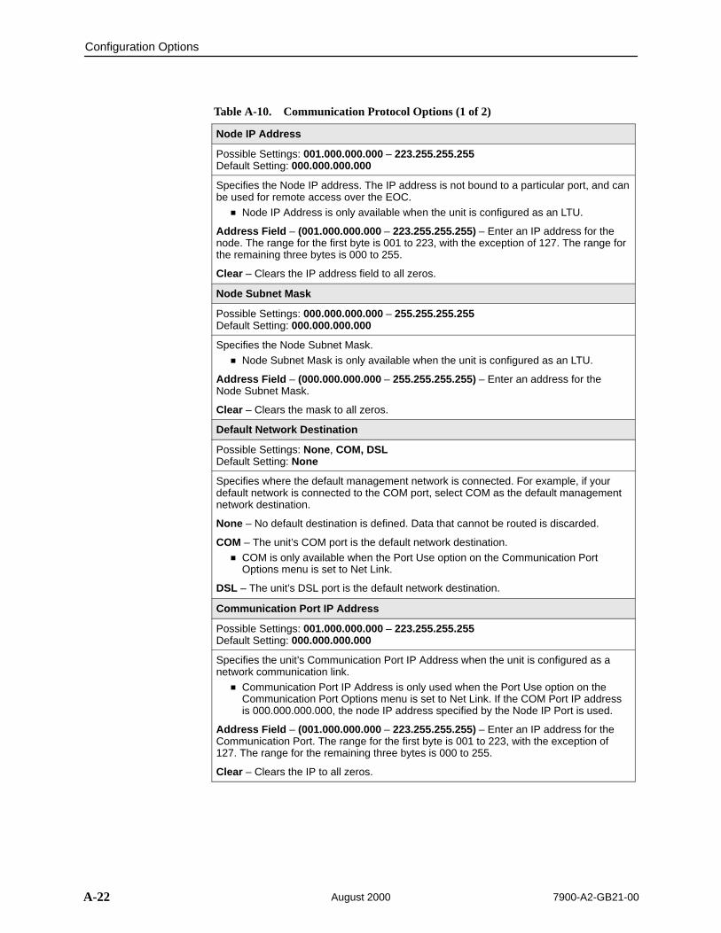
Configuration Options
A-22 7900-A2-GB21-00August 2000
Table A-10. Communication Protocol Options (1 of 2)
Node IP Address
Possible Settings: 001.000.000.000 – 223.255.255.255Default Setting: 000.000.000.000
Specifies the Node IP address. The IP address is not bound to a particular port, and canbe used for remote access over the EOC.
Node IP Address is only available when the unit is configured as an LTU.
Address Field – (001.000.000.000 – 223.255.255.255) – Enter an IP address for thenode. The range for the first byte is 001 to 223, with the exception of 127. The range forthe remaining three bytes is 000 to 255.
Clear – Clears the IP address field to all zeros.
Node Subnet Mask
Possible Settings: 000.000.000.000 – 255.255.255.255Default Setting: 000.000.000.000
Specifies the Node Subnet Mask. Node Subnet Mask is only available when the unit is configured as an LTU.
Address Field – (000.000.000.000 – 255.255.255.255) – Enter an address for theNode Subnet Mask.
Clear – Clears the mask to all zeros.
Default Network Destination
Possible Settings: None, COM, DSLDefault Setting: None
Specifies where the default management network is connected. For example, if yourdefault network is connected to the COM port, select COM as the default managementnetwork destination.
None – No default destination is defined. Data that cannot be routed is discarded.
COM – The unit’s COM port is the default network destination. COM is only available when the Port Use option on the Communication Port
Options menu is set to Net Link.
DSL – The unit’s DSL port is the default network destination.
Communication Port IP Address
Possible Settings: 001.000.000.000 – 223.255.255.255Default Setting: 000.000.000.000
Specifies the unit’s Communication Port IP Address when the unit is configured as anetwork communication link.
Communication Port IP Address is only used when the Port Use option on theCommunication Port Options menu is set to Net Link. If the COM Port IP addressis 000.000.000.000, the node IP address specified by the Node IP Port is used.
Address Field – (001.000.000.000 – 223.255.255.255) – Enter an IP address for theCommunication Port. The range for the first byte is 001 to 223, with the exception of127. The range for the remaining three bytes is 000 to 255.
Clear – Clears the IP to all zeros.

Configuration Options
A-237900-A2-GB21-00 August 2000
Table A-10. Communication Protocol Options (2 of 2)
Communication Port Subnet Mask
Possible Settings: 000.000.000.000 – 255.255.255.255Default Setting: 000.000.000.000
Specifies the unit’s Communication Port Subnet Mask when the unit is configured as anetwork communication link.
Communication Port Subnet Mask is only used when the Port Use option on theCommunication Port Options menu is set to Net Link. If the COM Port IP addressis not set (000.000.000.000), the node IP Address and subnet mask are used.
Address Field – (000.000.000.000 – 255.255.255.255) – Enter an address for theCommunication Port Subnet Mask.
Clear – Clears the mask to all zeros.
Communication Port Link Protocol
Possible Settings: PPP, SLIPDefault Setting: PPP
Specifies the unit’s Communication Port link layer protocol when the unit is configuredas a network communication link.
Communication Port Link Protocol is only used when the Port Use option on theCommunication Port Options menu is set to Net Link.
PPP – Defines Point-to-Point protocol for the link layer protocol for the networkcommunication link.
SLIP – Serial Line IP Protocol for the link layer protocol for the network communicationlink.

Configuration Options
A-24 7900-A2-GB21-00August 2000
General SNMP Management Options
To access the General SNMP Management Options screen, follow this menuselection sequence:
Main Menu →Configuration →Load Configuration From →Edit →Management and Communication →SNMP
ÎÎ
ÎÎÎÎ
main/config/management/SNMP Model: 797x
GENERAL SNMP MANAGEMENT OPTIONS
SNMP Management: Enable
Community Name 1: Public ClearName 1 Access: Read/WriteCommunity Name 2: Public ClearName 2 Access: Read/Write
–––––––––––––––––––––––––––––––––––––––––––––––––––––––––––––––––––––––––––––––Ctrl-a to access these functions, ESC for previous menu MainMenu Exit Save

Configuration Options
A-257900-A2-GB21-00 August 2000
Table A-11. General SNMP Management Options
SNMP Management
Possible Settings: Enable, DisableDefault Setting: Disable
Enables or disables the SNMP management features.
Enable – Enables SNMP management capabilities.
Disable – Disables SNMP management capabilities.
Community Name 1
Possible Settings: [ASCII text field]Default Text: public
Identifies the name of the community allowed to access the unit’s MIB. The communityname must be supplied by an external SNMP manager when that manager attempts toaccess an object in the MIB.
Text Field – Enter or edit a community name.
Clear – Clears the community name field.
Name 1 Access
Possible Settings: Read, Read/WriteDefault Setting: Read
Determines the access level for Community Name 1.
Read – Allows read-only access (get) for Community Name 1.
Read/Write – Allows read/write access (get) for Community Name 1.
Community Name 2
Possible Settings: [ASCII text field]Default Text: [null string]
Identifies the name of the second community allowed to access the unit’s MIB. Thecommunity name must be supplied by an external SNMP manager when that managerattempts to access an object in the MIB.
Text Field – Enter or edit a community name.
Clear – Clears the community name field.
Name 2 Access
Possible Settings: Read, Read/WriteDefault Setting: Read
Determines the access level for Community Name 2.
Read – Allows read-only access (get) for Community Name 2.
Read/Write – Allows read/write access (get/set) for Community Name 2.
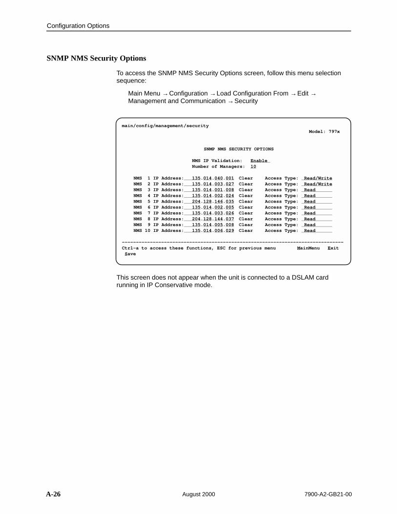
Configuration Options
A-26 7900-A2-GB21-00August 2000
SNMP NMS Security Options
To access the SNMP NMS Security Options screen, follow this menu selectionsequence:
Main Menu →Configuration →Load Configuration From →Edit →Management and Communication →Security
ÎÎÎÎÎÎÎÎÎÎÎÎÎÎÎÎÎÎÎÎÎÎÎÎÎÎÎÎÎÎÎÎÎÎÎÎÎÎÎÎÎÎÎÎÎÎÎÎÎÎÎÎÎÎÎÎÎÎÎÎÎÎÎÎÎÎÎÎÎÎÎÎÎÎÎÎÎÎÎÎÎÎÎÎÎÎÎÎÎÎÎÎÎÎÎÎÎÎÎÎÎÎÎÎÎÎÎÎÎÎÎÎÎÎÎÎÎÎÎÎÎÎÎÎÎÎÎÎÎÎÎÎÎÎÎÎÎÎÎÎÎÎÎÎÎÎÎÎÎÎÎÎÎÎÎÎÎÎÎÎÎÎÎÎÎÎÎÎÎÎÎÎÎÎÎÎÎÎÎÎÎÎÎÎÎÎÎÎÎÎÎÎÎÎÎÎÎÎÎÎÎÎÎÎÎÎÎÎÎÎÎÎÎÎÎÎÎÎÎÎÎÎÎÎÎÎÎÎÎÎÎÎÎÎÎÎÎÎÎÎÎÎÎÎÎÎÎÎÎÎÎÎÎÎÎÎÎÎÎÎÎÎÎÎÎÎÎÎÎÎÎÎÎÎÎÎÎÎÎÎÎÎÎÎÎÎÎÎÎÎÎÎÎÎÎÎÎÎÎÎÎÎÎÎÎÎÎÎÎÎÎÎÎÎÎÎÎÎÎÎÎÎÎÎÎÎÎÎÎÎÎÎÎÎÎÎÎÎÎÎÎÎÎÎÎÎÎÎÎÎÎÎÎÎÎÎÎÎÎÎÎÎÎÎÎÎÎÎÎÎÎÎÎÎÎÎÎÎÎÎÎÎÎÎÎÎÎÎÎÎÎÎÎÎÎÎÎÎÎÎ
main/config/management/security Model: 797x
SNMP NMS SECURITY OPTIONS
NMS IP Validation: Enable Number of Managers: 10
NMS 1 IP Address: 135.014.040.001 Clear Access Type: Read/WriteNMS 2 IP Address: 135.014.003.027 Clear Access Type: Read/WriteNMS 3 IP Address: 135.014.001.008 Clear Access Type: Read NMS 4 IP Address: 135.014.002.024 Clear Access Type: Read NMS 5 IP Address: 204.128.146.035 Clear Access Type: Read NMS 6 IP Address: 135.014.002.005 Clear Access Type: Read NMS 7 IP Address: 135.014.003.026 Clear Access Type: Read NMS 8 IP Address: 204.128.144.037 Clear Access Type: Read NMS 9 IP Address: 135.014.005.008 Clear Access Type: Read NMS 10 IP Address: 135.014.006.029 Clear Access Type: Read
–––––––––––––––––––––––––––––––––––––––––––––––––––––––––––––––––––––––––––––––Ctrl-a to access these functions, ESC for previous menu MainMenu Exit Save
This screen does not appear when the unit is connected to a DSLAM cardrunning in IP Conservative mode.

Configuration Options
A-277900-A2-GB21-00 August 2000
Table A-12. SNMP NMS Security Options
NMS IP Validation
Possible Settings: Enable, DisableDefault Setting: Disable
Specifies whether security checking is performed on the IP address of SNMPmanagement systems attempting to access the node.
Enable – Security checking is performed on the IP address of SNMP managementsystems attempting to access the node.
Disable – No security checking is performed.
Number of Managers
Possible Settings: 1, 2, 3, 4, 5, 6, 7, 8, 9, 10Default Setting: 1
Specifies the number of SNMP management systems that can send SNMP messages.
1 to 10 – Number of trap managers. An NMS IP address is required for each manager.
NMS n IP Address
Possible Settings: 001.000.000.000 – 223.255.255.255, ClearDefault Setting: 000.000.000.000
Specifies the Internet Protocol address used to identify each SNMP trap manager.
001.000.000.000 – 223.255.255.255 – Enter an address for each SNMP trap manager.The range for the first byte is 001 to 223, with the exception of 127. The range for theremaining three bytes is 000 to 255.
Clear – Clears the IP address to all zeros.
Access Level
Possible Settings: Read, Read/WriteDefault Setting: Read
Determines the access level allowed for an authorized NMS when IP address validationis being performed.
Read – Allows read-only access (get) to the accessible objects in the MIB for thisdevice.
Read/Write – Allows read/write access (get/set) to the accessible objects in the MIB forthis device.
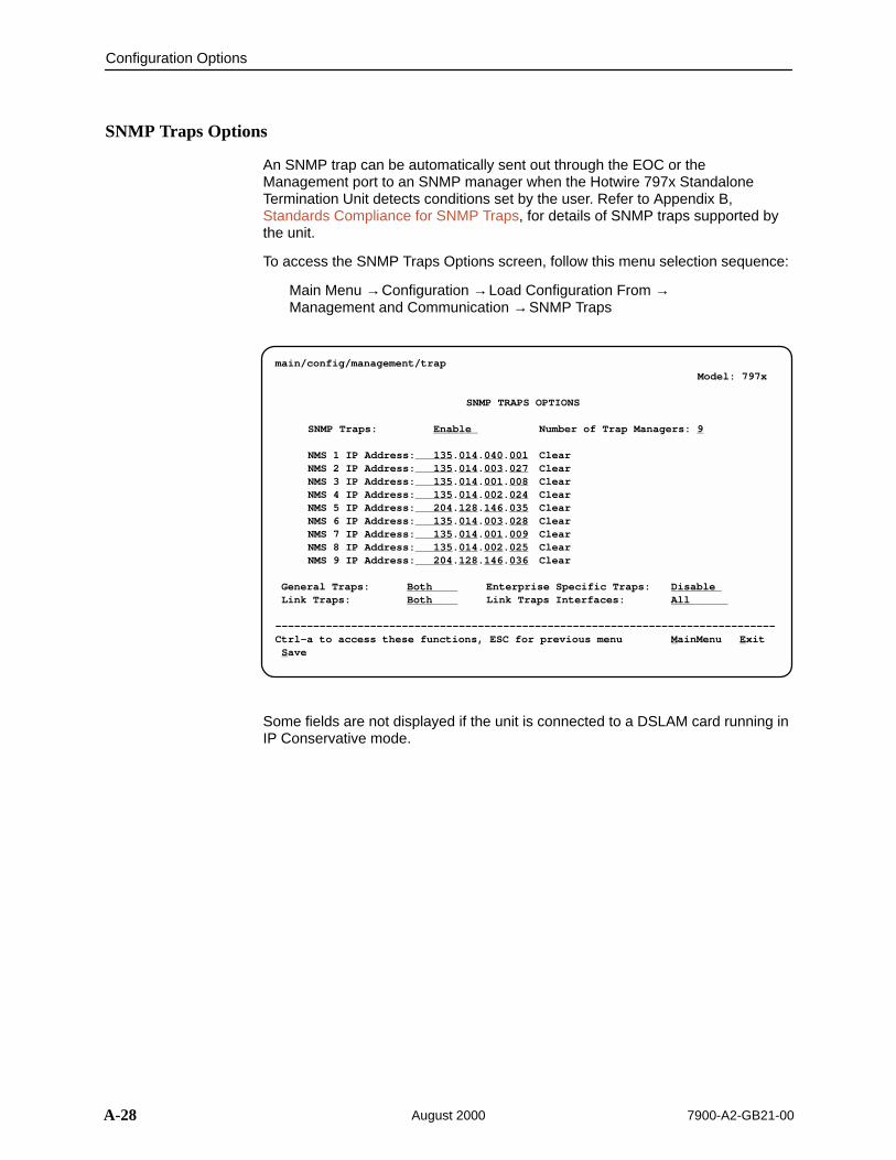
Configuration Options
A-28 7900-A2-GB21-00August 2000
SNMP Traps Options
An SNMP trap can be automatically sent out through the EOC or theManagement port to an SNMP manager when the Hotwire 797x StandaloneTermination Unit detects conditions set by the user. Refer to Appendix B,Standards Compliance for SNMP Traps, for details of SNMP traps supported bythe unit.
To access the SNMP Traps Options screen, follow this menu selection sequence:
Main Menu →Configuration →Load Configuration From →Management and Communication →SNMP Traps
ÎÎÎÎÎÎÎÎÎÎÎÎÎÎÎÎÎÎÎÎÎÎÎÎÎÎÎÎÎÎÎÎÎÎÎÎÎÎÎÎÎÎÎÎÎÎÎÎÎÎÎÎÎÎÎÎÎÎÎÎÎÎÎÎÎÎÎÎÎÎÎÎÎÎÎÎÎÎÎÎÎÎÎÎÎÎÎÎÎÎÎÎÎÎÎÎÎÎÎÎÎÎÎÎÎÎÎÎÎÎÎÎÎÎÎÎÎÎÎÎÎÎÎÎÎÎÎÎÎÎÎÎÎÎÎÎÎÎÎÎÎÎÎÎÎÎÎÎÎÎÎÎÎÎÎÎÎÎÎÎÎÎÎÎÎÎÎÎÎÎÎÎÎÎÎÎÎÎÎÎÎÎÎÎÎÎÎÎÎÎÎÎÎÎÎÎÎÎÎÎÎÎÎÎÎÎÎÎÎÎÎÎÎÎÎÎÎÎÎÎÎÎÎÎÎÎÎÎÎÎÎÎÎÎÎÎÎÎÎÎÎÎÎÎÎÎÎÎÎÎÎÎÎÎÎÎÎÎÎÎÎÎÎÎÎÎÎÎÎÎÎÎÎÎÎÎÎÎÎÎÎÎÎÎÎÎÎÎÎÎÎÎÎÎÎÎÎÎÎÎÎÎÎÎÎÎÎÎÎÎÎÎÎÎÎÎÎÎÎÎÎÎÎÎÎÎÎÎÎÎÎÎÎÎÎÎÎÎÎÎÎÎÎÎÎÎÎÎÎÎÎÎÎÎÎÎÎÎÎÎÎÎÎÎÎÎÎÎÎÎÎÎÎÎÎÎÎÎÎÎÎÎÎÎÎÎÎÎÎÎÎÎÎÎÎÎÎÎÎÎ
main/config/management/trap Model: 797x
SNMP TRAPS OPTIONS
SNMP Traps: Enable Number of Trap Managers: 9
NMS 1 IP Address: 135.014.040.001 Clear NMS 2 IP Address: 135.014.003.027 Clear NMS 3 IP Address: 135.014.001.008 Clear NMS 4 IP Address: 135.014.002.024 Clear NMS 5 IP Address: 204.128.146.035 Clear NMS 6 IP Address: 135.014.003.028 Clear NMS 7 IP Address: 135.014.001.009 Clear NMS 8 IP Address: 135.014.002.025 Clear NMS 9 IP Address: 204.128.146.036 Clear
General Traps: Both Enterprise Specific Traps: Disable Link Traps: Both Link Traps Interfaces: All
–––––––––––––––––––––––––––––––––––––––––––––––––––––––––––––––––––––––––––––––Ctrl-a to access these functions, ESC for previous menu MainMenu Exit Save
Some fields are not displayed if the unit is connected to a DSLAM card running inIP Conservative mode.
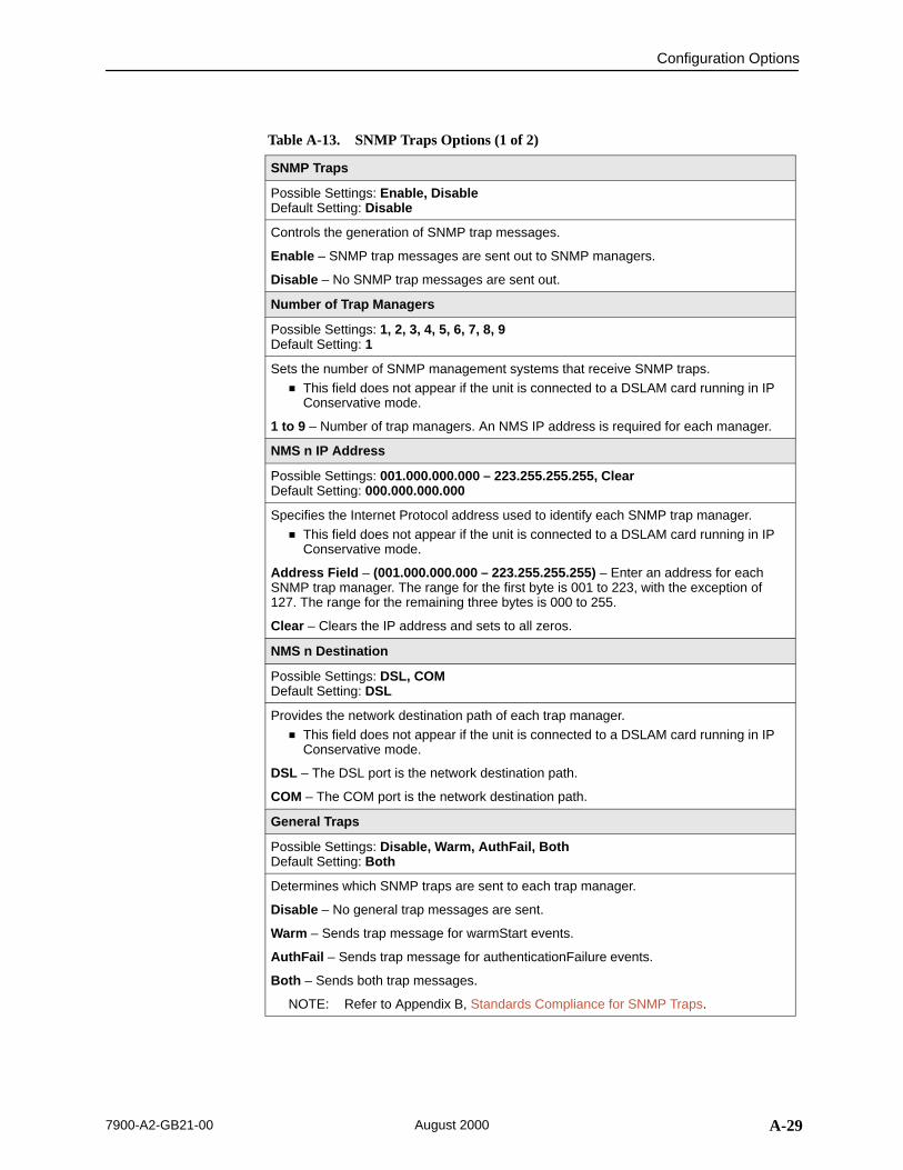
Configuration Options
A-297900-A2-GB21-00 August 2000
Table A-13. SNMP Traps Options (1 of 2)
SNMP Traps
Possible Settings: Enable, DisableDefault Setting: Disable
Controls the generation of SNMP trap messages.
Enable – SNMP trap messages are sent out to SNMP managers.
Disable – No SNMP trap messages are sent out.
Number of Trap Managers
Possible Settings: 1, 2, 3, 4, 5, 6, 7, 8, 9Default Setting: 1
Sets the number of SNMP management systems that receive SNMP traps. This field does not appear if the unit is connected to a DSLAM card running in IP
Conservative mode.
1 to 9 – Number of trap managers. An NMS IP address is required for each manager.
NMS n IP Address
Possible Settings: 001.000.000.000 – 223.255.255.255, ClearDefault Setting: 000.000.000.000
Specifies the Internet Protocol address used to identify each SNMP trap manager. This field does not appear if the unit is connected to a DSLAM card running in IP
Conservative mode.
Address Field – (001.000.000.000 – 223.255.255.255) – Enter an address for eachSNMP trap manager. The range for the first byte is 001 to 223, with the exception of127. The range for the remaining three bytes is 000 to 255.
Clear – Clears the IP address and sets to all zeros.
NMS n Destination
Possible Settings: DSL, COMDefault Setting: DSL
Provides the network destination path of each trap manager. This field does not appear if the unit is connected to a DSLAM card running in IP
Conservative mode.
DSL – The DSL port is the network destination path.
COM – The COM port is the network destination path.
General Traps
Possible Settings: Disable, Warm, AuthFail, BothDefault Setting: Both
Determines which SNMP traps are sent to each trap manager.
Disable – No general trap messages are sent.
Warm – Sends trap message for warmStart events.
AuthFail – Sends trap message for authenticationFailure events.
Both – Sends both trap messages.
NOTE: Refer to Appendix B, Standards Compliance for SNMP Traps.

Configuration Options
A-30 7900-A2-GB21-00August 2000
Table A-13. SNMP Traps Options (2 of 2)
Enterprise Specific Traps
Possible Settings: Enable, DisableDefault Setting: Disable
Determines if SNMP traps are generated for enterprise-specific events.
Enable – SNMP traps are generated for enterpriseSpecific events.
NOTE: Refer to Enterprise Specific Traps in Appendix B, Standards Compliancefor SNMP Traps.
Disable – No enterprise-specific event traps are sent.
Link Traps
Possible Settings: Disable, Up, Down, BothDefault Setting: Both
Determines if SNMP traps are generated for link up and link down for one of thecommunication interfaces.
Disable – No linkUp or linkDown SNMP traps are generated.
Up – A linkUp trap is generated when the unit recognizes that one of the communicationinterfaces is operational.
Down – A linkDown trap is generated when the unit recognizes a failure in one of thecommunication interfaces.
Both – Sends trap messages for detection of both linkUp and linkDown.
NOTE: Refer to linkUp and linkDown in Appendix B, Standards Compliance forSNMP Traps.
Link Traps Interfaces
Possible Settings: Network, [DSX-1, SYNC, or G.703], AllDefault Setting: All
Determines if the SNMP linkUp, SNMP linkDown, and interface-relatedenterpriseSpecific traps are generated for the network interface, DTE port, or both.Depending on the model, the DTE option appears as DSX-1, SYNC, or G.703.
Network – SNMP trap messages are generated for the network interface.
DSX-1, SYNC, or G.703 – SNMP trap messages are generated for the DTE port.
All – SNMP trap messages are generated for the network interface and the DTE ports.

B-17900-A2-GB21-00 August 2000
Standards Compliance forSNMP Traps
BSNMP Traps
This section describes the unit’s compliance with SNMP standards and anyspecial operational features for the SNMP traps supported. The unit supports thefollowing traps:
warmStart
authenticationFailure
linkUp
linkDown
Enterprise-specific traps
ifIndex Variable Binding
The following ifIndex values are supported for Hotwire 797x StandaloneTermination Units:
ifIndex Description Supported by . . .
1 COM Port All models
2 DSL Interface All models
6 DSX-1 or G.703 Interface Models 7974 and 7976
10 EIA-530-A Interface Model 7975
14 EOC Management Link All models

Standards Compliance for SNMP Traps
B-2 7900-A2-GB21-00August 2000
In general, all traps have at a minimum a variable binding of ifIndex. For astandalone NTU connected to a DSLAM running IP Conservative software, alltraps have at a minimum a variable binding of the Super Overloaded ifIndex(SOI). The formula for the SOI is:
((LTU Slot Number) * 1,000,000) + ((LTU DSL Port Number) * 1,000) + the NTU’s ifIndex.
warmStart
SNMP Trap Description Possible Cause
warmStart The unit has reinitializeditself.
The trap is sent after the unitresets and stabilizes.
There are no variablebindings.
Reset command.
Power disruption.
authenticationFailure
SNMP Trap Description Possible Cause
authenticationFailure Failed attempts to accessthe unit.
Variable bindings:
devAuthenticationFailureIPAddress (Health & Status MIB)
Returns zero if the IPaddress is unknown or thefailure came from theterminal port.
Three unsuccessful attemptswere made to enter a correctlogin/password combination.

Standards Compliance for SNMP Traps
B-37900-A2-GB21-00 August 2000
linkUp and linkDown
The link SNMP traps are:
linkUp – The unit recognizes that one of the communication interfaces isoperational.
linkDown – The unit recognizes that one of the communication interfaces isnot operational.
The network and synchronous port interfaces (physical sublayer) are representedby an entry in the MIB-II interfaces table and supported by the DS1 MIB.
The following list describes the conditions that define linkUp and linkDown:
linkUp/Down variable bindings
ifIndex (RFC 1573)This object provides the index into the ifTable and potentially into tables in other MIBs.The ifIndexes supported are:– 1 COM Port– 2 DSL Network Interface– 6 DSX-1 or G.703 Port– 10 EIA-530-A Port– 14 EOC Management Link
ifAdminStatus (RFC 1573)This object specifies the operational state of the interface:– up(1)
The interface is enabled.– down(2)
The interface is disabled.
ifOperStatus (RFC 1573)This object specifies the operational state of the interface:– up(1)
COM Port: Always up unless defined as a Net Link, in which case status iscontrolled by link layer protocol and control leads.DSL Port: DSL link is established and no alarms exist.DSX-1 or G.703 Port: No alarm conditions exist.EIA-530-A Port: Port is enabled and configured control leads are on.EOC: Based on the state of the link layer protocol.
– down(2)COM Port: Down status is controlled by link layer protocol and control leads.DSL Port: DSL link is not established or alarms exist.DSX-1 or G.703 Port: Alarm condition exists.EIA-530-A Port: Port is disabled or a configured control lead is off.EOC: Based on the state of the link layer protocol.
– testing(3)DSL, DSX-1, G.703, or EIA-530-A Port: A test is active on the port.
– dormant(5)DSL Port: DSL link is negotiating.
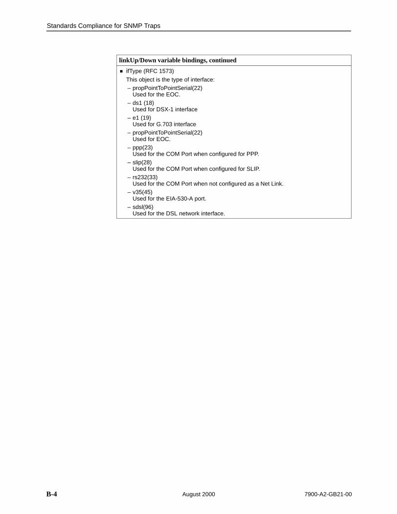
Standards Compliance for SNMP Traps
B-4 7900-A2-GB21-00August 2000
linkUp/Down variable bindings, continued
ifType (RFC 1573)
This object is the type of interface:– propPointToPointSerial(22)
Used for the EOC.– ds1 (18)
Used for DSX-1 interface– e1 (19)
Used for G.703 interface– propPointToPointSerial(22)
Used for EOC.– ppp(23)
Used for the COM Port when configured for PPP.– slip(28)
Used for the COM Port when configured for SLIP.– rs232(33)
Used for the COM Port when not configured as a Net Link.– v35(45)
Used for the EIA-530-A port.– sdsl(96)
Used for the DSL network interface.

Standards Compliance for SNMP Traps
B-57900-A2-GB21-00 August 2000
Enterprise-Specific Traps
The enterpriseSpecific trap indicates that an enterprise-specific event hasoccurred. The Specific-trap field identifies the particular trap that occurred. Thefollowing table lists the enterprise-specific traps supported by the unit:
SNMP Trap Description Possible Cause
enterprisePrimaryClockFail(1)
The unit has lost its primaryclock source.
No variable bindings.
Hardware failure in the unitor the clock source.
enterpriseSelfTestFail(2) A hardware failure of theunit is detected during theunit’s self-test. The trap isgenerated after the unitcompletes initialization.
Variable bindings:
devSelfTestResults
Failure of one or more of theunit’s hardware components.
enterpriseDeviceFail(3) An internal device failure.
No variable bindings.
Operating software hasdetected an internal devicefailure.
enterpriseSecondaryClockFail(4)
The unit has lost itssecondary clock source.
No variable bindings.
Hardware failure in the unitor the clock source.
enterpriseTestStart(5) A test is running.
Variable bindings:
devSelfTestResults
ifIndex (RFC 1573)
ifAdminStatus (RFC 1573)
ifOperStatus (RFC 1573)
ifType (RFC 1573)
ifTestType (RFC 1573)
At least one test has beenstarted on an interface.
enterpriseConfigChange(6) The configuration changedvia the user interface. Thetrap is sent after 60 seconds have elapsedwithout another change.This suppresses thesending of numerous trapswhen multiple changes aremade in a short period oftime, as is typically thecase when changingconfiguration options.
No variable bindings.
Configuration has beenchanged via the ATI.

Standards Compliance for SNMP Traps
B-6 7900-A2-GB21-00August 2000
SNMP Trap Possible CauseDescription
enterpriseFallbackAutoRate(13)
After a loss of signal, theunit resynchronized to alower rate than the lastknown rate.
Variable bindings:
ifIndex (RFC 1573)
ifAdminStatus (RFC 1573)
ifOperStatus (RFC 1573)
ifType (RFC 1573)
Variable line conditions.
enterprisePrimaryClockFailClear(101)
The LTU has recovered andis using its primary clocksource.
No variable bindings.
enterpriseSecondaryClockFailClear(104)
The LTU has recovered andis using its secondary clocksource.
No variable bindings.
enterpriseTestStop(105) All tests have been halted.
Variable bindings:
ifIndex (RFC 1573)
ifAdminStatus (RFC 1573)
ifOperStatus (RFC 1573)
ifType (RFC 1573)
ifTestType (RFC 1573)
All tests on an interfacehave been stopped bytimeout or an Abort All Testscommand.
enterpriseFallbackAutoRateClear(113)
After an AutoRate fallbackcondition, the unitresynchronized to the lastknown rate.
Variable bindings:
ifIndex (RFC 1573)
ifAdminStatus (RFC 1573)
ifOperStatus (RFC 1573)
ifType (RFC 1573)

Standards Compliance for SNMP Traps
B-77900-A2-GB21-00 August 2000
The tests that affect the enterpriseTestStart and enterpriseTestStop traps and thevariable bindings depend on the interface. The specific tests and variablebindings are described in the following table:
InterfaceenterpriseTestStart/Stop variablebindings Possible Cause
DSL Network ifIndex (RFC 1573)
ifAdminStatus (RFC 1573)
ifOperStatus (RFC 1573)
ifType (RFC 1573)
ifTestType (RFC 1573)The following objects control testsin SNMP-managed devices:– noTest(0) – Stops the test in
progress.– testLoopLLB(4) – Initiates a
Local Loopback.– testSendMon511(6) – Initiates a
Send and Monitor 511 test.– testSendLLBUp(7) – Initiates an
LLB Up message to the remoteunit.
– testSendLLBDown(8) – Initiatesan LLB Down message to theremote unit.
enterpriseTest Start – Anyone of the following tests isactive on the interface:– Line Loopback– Remote Line Loopback– Send and Monitor 511
enterpriseTest Stop – No testscurrently running on theinterface.
DSX-1 orG.703
ifIndex (RFC 1573)
ifAdminStatus (RFC 1573)
ifOperStatus (RFC 1573)
ifType (RFC 1573)
ifTestType (RFC 1573)The following objects control testsin SNMP-managed devices:– noTest(0) – Stops the test in
progress.– testLoopDTLB(3) – Initiates a
DTE Loopback.– testLoopPLB(1) – A
Telco-initiated PayloadLoopback is active on theinterface (DSX-1 only).
– testLoopRLB(5) – Initiates aRemote Loopback.
enterpriseTest Start – Anyone of the following tests isactive on the interface:– DTE Loopback– Repeater Loopback– Telco Payload Loopback
(DSX-1 only)
enterpriseTest Stop – No testscurrently running on theinterface.

Standards Compliance for SNMP Traps
B-8 7900-A2-GB21-00August 2000
Interface Possible CauseenterpriseTestStart/Stop variablebindings
EIA-530-A ifIndex (RFC 1573)
ifAdminStatus (RFC 1573)
ifOperStatus (RFC 1573)
ifType (RFC 1573)
ifTestType (RFC 1573)The following objects control testsin SNMP-managed devices:– noTest(0) – Stops the test in
progress.– testLoopDCLB(3) – Initiates a
Data Channel Loopback.– testLoopDTLB(3) – Initiates a
DTE Loopback.– testLoopRLB(5) – Initiates a
Remote Loopback.– testSendDCLBUp(9) – Initiates a
Data Channel Loopback Upmessage.
– testSendDCLBDown(10) –Initiates a Data ChannelLoopback Down message.
enterpriseTest Start – Anyone of the following tests isactive on the interface:– Data Channel Loopback– DTE Loopback– Repeater Loopback
enterpriseTest Stop – No testscurrently running on theinterface.

C-17900-A2-GB21-00 August 2000
Cables and Pin Assignments
COverview
The following sections provide pin assignments for:
Power Input Connector
COM Port Connector
COM Port-to-PC Cable
COM Port-to-LAN Adapter Cable
DSX-1/G.703 Network Interface
EIA-530-A Port
EIA-530-A-to-X.21 Interface
EIA-530-A-to-RS-449 Interface
EIA-530-A-to-V.35 Interface
DSL Network Interface Cable

99-16291
23
5 46
1
Cables and Pin Assignments
C-2 7900-A2-GB21-00August 2000
Power Input Connector
The input power connector leads are shown in Table C-1. Pin 1 is at the lowerright of the connector and Pin 6 at the upper left as you face the back of the unit.
Table C-1. Power Input Connector
Pin Number Wire Color Signal
1 Black –48 Vdc Return
2 Red –48 Vdc Return
3 Green Ground
4 White +24 Vdc Return
5 Orange –48 Vdc
+24 Vdc
6 Blue No Connection

Cables and Pin Assignments
C-37900-A2-GB21-00 August 2000
COM Port Connector
The COM port connector is an 8-position unkeyed modular jack (Table C-2). Thedata signals on this port are referenced to a DTE interface.
Table C-2. COM Port Connector (J6)
Signal Direction Pin Number
Transmit Clock to DTE (Out) 1
DCE Received Data to DTE (Out) 2
Signal Ground — 3
DCE Transmit Data from DTE (IN) 4
DCE Data Terminal Ready from DTE (IN) 5
DCE Carrier Detect to DTE Out) 6
DCE Request to Send from DTE (IN) 7
Receive Clock to DTE (Out) 8

Cables and Pin Assignments
C-4 7900-A2-GB21-00August 2000
COM Port-to-PC Cable
The COM port can be connected to an asynchronous terminal or a PC runningterminal emulation software. The COM port-to-PC cable is a 14-foot, 26 AWG,8-conductor cable with an 8-position unkeyed modular connector and a DB9socket connector (Figure C-1).
98-15886
Figure C-1. COM Port-to-PC Cable (Feature Number 3100-F2-550)
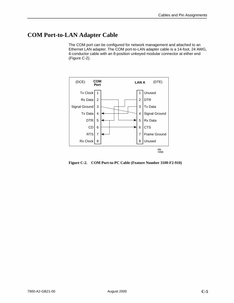
Cables and Pin Assignments
C-57900-A2-GB21-00 August 2000
COM Port-to-LAN Adapter Cable
The COM port can be configured for network management and attached to anEthernet LAN adapter. The COM port-to-LAN adapter cable is a 14-foot, 24 AWG,6-conductor cable with an 8-position unkeyed modular connector at either end(Figure C-2).
Tx Clock
Rx Data
Signal Ground
Tx Data
DTR
CD
RTS
Rx Clock
Unused
DTR
Tx Data
Signal Ground
Rx Data
CTS
Frame Ground
Unused
COMPort
LAN A
496-14908
1
2
3
4
5
6
7
8
1
2
3
4
5
6
7
8
(DCE) (DTE)
Figure C-2. COM Port-to-PC Cable (Feature Number 3100-F2-910)
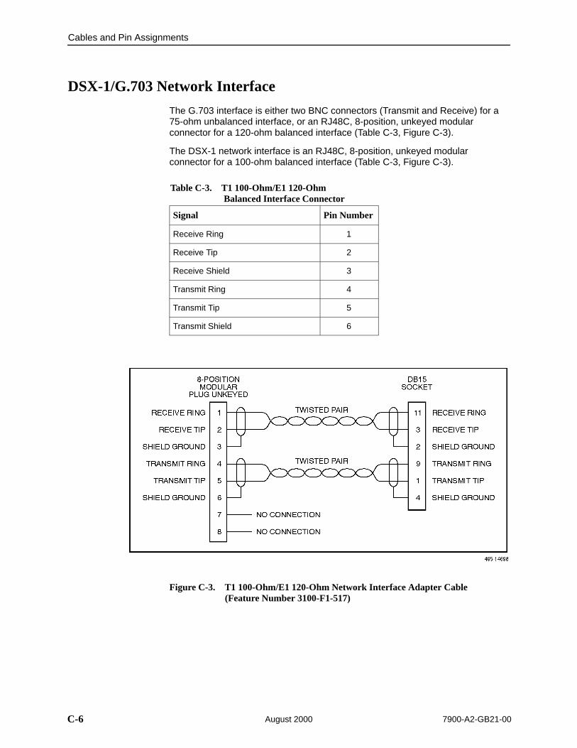
Cables and Pin Assignments
C-6 7900-A2-GB21-00August 2000
DSX-1/G.703 Network Interface
The G.703 interface is either two BNC connectors (Transmit and Receive) for a75-ohm unbalanced interface, or an RJ48C, 8-position, unkeyed modularconnector for a 120-ohm balanced interface (Table C-3, Figure C-3).
The DSX-1 network interface is an RJ48C, 8-position, unkeyed modularconnector for a 100-ohm balanced interface (Table C-3, Figure C-3).
Table C-3. T1 100-Ohm/E1 120-Ohm Balanced Interface Connector
Signal Pin Number
Receive Ring 1
Receive Tip 2
Receive Shield 3
Transmit Ring 4
Transmit Tip 5
Transmit Shield 6
Figure C-3. T1 100-Ohm/E1 120-Ohm Network Interface Adapter Cable(Feature Number 3100-F1-517)

Cables and Pin Assignments
C-77900-A2-GB21-00 August 2000
EIA-530-A Port
The EIA-530-A Port interface connector information is shown in Table C-4.
Table C-4. EIA-530-A Port Interface Connector
SignalCircuitMnemonic
ITU-TNumber Direction Pin
Shield — — — 1
Signal Common AB 102A — 7
Signal Common AC 102B — 23
Transmitted Data BA 103 To DSU/CSU 2 (A)14 (B)
Received Data BB 104 From DSU/CSU 3 (A)16 (B)
Request to Send CA 105 To DSU/CSU 4 (A)19 (B)
Clear to Send CB 106 From DSU/CSU 5 (A)13 (B)
Received Line Signal Detector CF 109 From DSU/CSU 8 (A)10 (B)
DCE Ready CC 107 From DSU/CSU 6
DTE Ready CD 108/1, /2 To DSU/CSU 20
Transmit Signal Element Timing (DTE Source)
DA 113 To DSU/CSU 11 (B)24 (A)
Transmit Signal Element Timing (DCE Source)
DB 114 From DSU/CSU 12 (B)15 (A)
Receiver Signal Element Timing (DCE Source)
DD 115 From DSU/CSU 17 (A)9 (B)
Local Loopback LL 141 To DSU/CSU 18
Remote Loopback RL 140 To DSU/CSU 21
Test Mode TM 142 From DSU/CSU 25
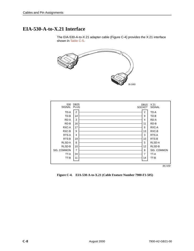
Cables and Pin Assignments
C-8 7900-A2-GB21-00August 2000
EIA-530-A-to-X.21 Interface
The EIA-530-A-to-X.21 adapter cable (Figure C-4) provides the X.21 interfaceshown in Table C-5.
98-15883
2
14
3
16
17
9
4
19
8
10
7
24
11
2
9
4
11
6
13
3
10
5
12
8
7
14
TD-A
TD-B
RD-A
RD-B
RXC-A
RXC-B
RTS-A
RTS-B
RLSD-A
RLSD-B
SIG. COMMON
TT-A
TT-B
TD-A
TD-B
RD-A
RD-B
RXC-A
RXC-B
RTS-A
RTS-B
RLSD-A
RLSD-B
SIG. COMMON
TT-A
TT-B
530 SIGNAL
DB25PLUG
DB15SOCKET
X.21 SIGNAL
495-14787
Figure C-4. EIA-530-A-to-X.21 (Cable Feature Number 7900-F1-505)
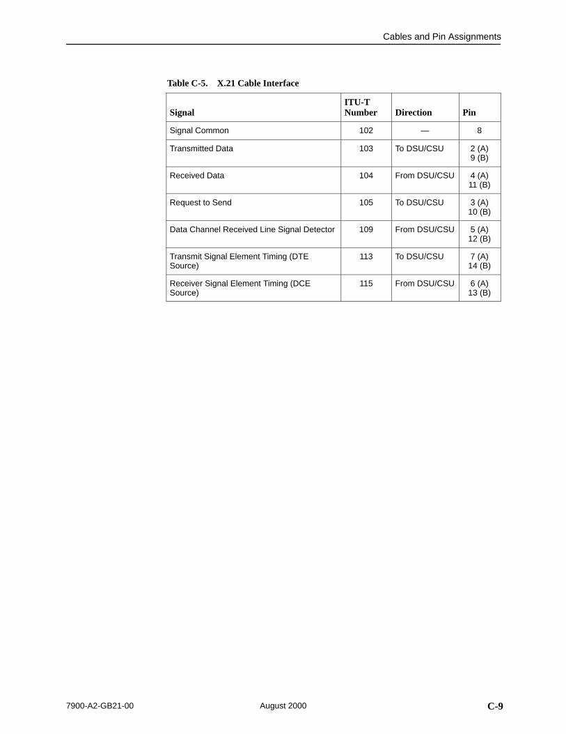
Cables and Pin Assignments
C-97900-A2-GB21-00 August 2000
Table C-5. X.21 Cable Interface
SignalITU-TNumber Direction Pin
Signal Common 102 — 8
Transmitted Data 103 To DSU/CSU 2 (A)9 (B)
Received Data 104 From DSU/CSU 4 (A)11 (B)
Request to Send 105 To DSU/CSU 3 (A)10 (B)
Data Channel Received Line Signal Detector 109 From DSU/CSU 5 (A)12 (B)
Transmit Signal Element Timing (DTESource)
113 To DSU/CSU 7 (A)14 (B)
Receiver Signal Element Timing (DCESource)
115 From DSU/CSU 6 (A)13 (B)

Cables and Pin Assignments
C-10 7900-A2-GB21-00August 2000
EIA-530-A-to-RS-449 Interface
The EIA-530-A-to-RS-449 adapter cable (Figure C-5) provides the RS-449interface shown in Table C-6.
98-15902
1
2
14
3
16
15
12
17
9
4
19
5
13
20
8
10
6
7
21
18
23
24
11
25
22
1
4
22
6
24
5
23
8
26
7
25
9
27
12
13
31
11
19
14
10
20
17
35
18
29
30
SHIELD
TD-A
TD-B
RD-A
RD-B
TXC-A
TXC-B
RXC-A
RXC-B
RTS-A
RTS-B
CTS-A
CTS-B
DTR
RLSD-A
RLSD-B
DSR
SIG. COMMON
RL
LL
RCV. COMMON
TT-A
TT-B
TM
SIG. COMMON
SHIELD
TD-A
TD-B
RD-A
RD-B
TXC-A
TXC-B
RXC-A
RXC-B
RTS-A
RTS-B
CTS-A
CTS-B
DTR-A
RR-A
RR-B
DM-A
SIG. COMMON
RL
LL
RCV. COMMON
TT-A
TT-B
TM
DM-B
DTR-B
530 SIGNAL
DB25PLUG
DB37SOCKET
449 SIGNAL
495-14323-01
Figure C-5. EIA-530-A-to-RS-449 Cable Pinouts (Feature Number 7900-F1-504)

Cables and Pin Assignments
C-117900-A2-GB21-00 August 2000
Table C-6. RS-449 Cable Interface
SignalCircuitMnemonic
ITU-TNumber Direction Pin
Shield — — — 1
Signal Ground SG 102A — 19
Receive Ground RC 102B — 20
Send Common SC — — 37
Send Data SD 103 To DSU/CSU 4 (A)22 (B)
Receive Data RD 104 From DSU/CSU 6 (A)24 (B)
Request to Send RS 105 To DSU/CSU 7 (A)25 (B)
Clear to Send CS 106 From DSU/CSU 9 (A)27 (B)
Receiver Ready RR 109 From DSU/CSU 13 (A)31 (B)
Data Mode DM 107 From DSU/CSU 11 (A)29 (B)
Terminal Ready TR 108/1, /2 To DSU/CSU 12 (A)30 (B)
Terminal Timing TT 113 To DSU/CSU 17 (A)35 (B)
Send Timing ST 114 From DSU/CSU 5 (A)23 (B)
Receive Timing RT 115 From DSU/CSU 8 (A)26 (B)
Local Loopback LL 141 To DSU/CSU 10
Remote Loopback RL 140 To DSU/CSU 14
Test Mode TM 142 From DSU/CSU 18
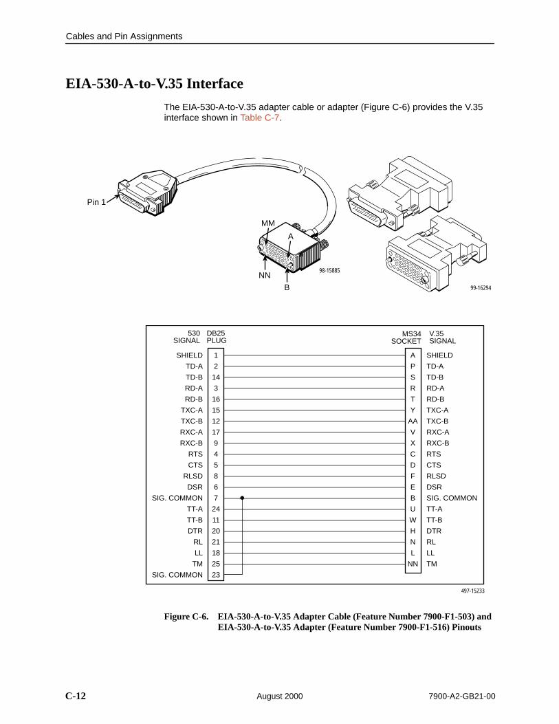
98-15885
Pin 1
MM
A
B
NN99-16294
Cables and Pin Assignments
C-12 7900-A2-GB21-00August 2000
EIA-530-A-to-V.35 Interface
The EIA-530-A-to-V.35 adapter cable or adapter (Figure C-6) provides the V.35interface shown in Table C-7.
1
2
14
3
16
15
12
17
9
4
5
8
6
7
24
11
20
21
18
25
23
A
P
S
R
T
Y
AA
V
X
C
D
F
E
B
U
W
H
N
L
NN
SHIELD
TD-A
TD-B
RD-A
RD-B
TXC-A
TXC-B
RXC-A
RXC-B
RTS
CTS
RLSD
DSR
SIG. COMMON
TT-A
TT-B
DTR
RL
LL
TM
SIG. COMMON
SHIELD
TD-A
TD-B
RD-A
RD-B
TXC-A
TXC-B
RXC-A
RXC-B
RTS
CTS
RLSD
DSR
SIG. COMMON
TT-A
TT-B
DTR
RL
LL
TM
530 SIGNAL
DB25PLUG
MS34SOCKET
V.35SIGNAL
497-15233
Figure C-6. EIA-530-A-to-V.35 Adapter Cable (Feature Number 7900-F1-503) and EIA-530-A-to-V.35 Adapter (Feature Number 7900-F1-516) Pinouts

Cables and Pin Assignments
C-137900-A2-GB21-00 August 2000
Table C-7. V.35 Cable Interface
SignalITU-TNumber Direction Pin
Shield — — A
Signal Common 102 — B
Transmitted Data 103 To DSU/CSU P (A)S (B)
Received Data 104 From DSU/CSU R (A)T (B)
Request to Send 105 To DSU/CSU C
Clear to Send 106 From DSU/CSU D
Data Channel Received Line Signal Detector 109 From DSU/CSU F
Data Set Ready 107 From DSU/CSU E
Data Terminal Ready 108/1, /2 To DSU/CSU H
Transmit Signal Element Timing (DTESource)
113 To DSU/CSU U (A)W (B)
Transmit Signal Element Timing (DCESource)
114 From DSU/CSU Y (A)AA (B)
Receiver Signal Element Timing (DCESource)
115 From DSU/CSU V (A)X (B)
Local Loopback 141 To DSU/CSU L
Loopback/Maintenance 140 To DSU/CSU N
Test Indicator 142 From DSU/CSU NN

Cables and Pin Assignments
C-14 7900-A2-GB21-00August 2000
DSL Network Interface Cable
The DSL line interface cable is a 20-foot, 24 AWG solid, 2-twisted-pair cable thatis RJ48C-to-RJ48C (Table C-8, Figure C-7).
Table C-8. DSL NetworkInterface Connector
Pin Number M/SDSL Signal
1 (Unused)
2 (Unused)
4 Ring
5 Tip
98-15954a
Ring
Tip
Ring
Tip
Twisted Pair
Twisted Pair
RJ48CPlug
1
2
3
4
5
6
7
8
RJ48CPlug
1
2
3
4
5
6
7
8
Blue
White
Orange
White
Blue
White
Orange
White
Blue
White
Orange
White
Blue
White
Orange
White
Blue
White
Orange
White
Blue
White
Orange
White
Blue
White
Orange
White
Blue
White
Orange
White
Blue
White
Orange
White
Blue
White
Orange
White
Figure C-7. DSL Network Interface Cable with RJ48C Connector (Feature Number 7900-F1-514)
97-15884
8-PinPlug
Pin #1
Pin #8

D-17900-A2-GB21-00 August 2000
Technical Specifications
DSpecifications Criteria*
Size Width 7.25 inches (18.4 cm)
Height 1.5 inches (3.8 cm)
Length 9.4 inch (24.9 cm)
Weight Approximately 1.25 lbs. (0.6 kg)
Approvals
Safety Certifications Refer to the equipment’s label for approvals on product.
Power +24 VDC or –48 VDC
Maximum Power Dissipation = 8.3 watts
Cables Feature Number Description
3100-F1-517 DSX-1/G.703 Network Interface Cable
3100-F2-550 COM Port-to-PC Cable
3100-F2-910 COM Port-to-LAN Adapter Cable
7900-F1-503 EIA-530-A-to-V.35 Adapter Cable
7900-F1-504 EIA-530-A-to-RS-449 Adapter Cable
7900-F1-505 EIA-530-A-to-X.21 Adapter Cable
7900-F1-506 Optional Power Cable
7900-F1-514 DSL Network Interface Cable
7900-F1-516 EIA-530-A-to-V.35 Adapter
Physical Environment
Operating temperature
Storage temperature
Relative humidity
32° to 122° F (0° to 50° C)
–4° F (–20° C) to 158° F (70° C)
5% to 85% (noncondensing)
* Technical specifications are subject to change without notice.

Technical Specifications
D-2 7900-A2-GB21-00August 2000

GL-17900-A2-GB21-00 August 2000
Glossary
A random bit test 511 bytes in length.
Alarm Indication Signal. A signal transmitted downstream instead of the normal signal topreserve transmission continuity and to indicate to the rest of the network that a faultexists. Also called a Blue Alarm.
Alternate Mark Inversion. A line coding technique used to accommodate the ones densityrequirements of E1 or T1 lines.
Asynchronous Terminal Interface. A menu-driven, VT100-compatible system forconfiguring and managing the termination unit.
A feature that allows a DSL termination unit to train to the optimal line rate.
Bipolar Violation. In a bipolar signal, a one (mark, pulse) which has the same polarity as itspredecessor.
Any part of the local loop that is not in the direct talking path between the CO and theservice user.
Carrierless Amplitude and Phase Modulation. A transmission technology for implementinga DSL. Transmit and receive signals are modulated into two wide-frequency bands usingpassband modulation techniques.
Carrier Detect. The received line signal detector. V.24 circuit 109.
Central Office/Central Site. The PSTN facility that houses one or more switches servinglocal telephone subscribers.
Communications port. A computer’s serial communications port used to transmit to andreceive data from a modem. The modem connects directly to this port.
Customer Premises.
Customer Premises Equipment. Terminal equipment on the service user’s side of thetelecommunications network interface.
Central Processing Unit. The main or only computing device in a data processing system.
Cyclic Redundancy Check. A mathematical method of confirming the integrity of receiveddigital data.
Clear To Send. A signal indicating that the device is ready for the DTE to transmit data.Usually occurs in response to Request To Send (RTS).
Code Violation. Detected when using HDB3 coding format, this is equivalent to a BPVwhen using AMI coding.
Data Communications Equipment. The equipment that provides the functions required toestablish, maintain, and end a connection. It also provides the signal conversion requiredfor communication between the DTE and the network.
Data Channel LoopBack. Loops the data received from the network interface, for all DS0channels allocated to the selected port, back to the network.
Digital Subscriber Line. The non-loaded, local-loop copper connection between thecustomer and the first node within the network.
511
AIS
AMI
ATI
AutoRate
BPV
bridged tap
CAP
CD
CO
COM port
CP
CPE
CPU
CRC
CTS
CV
DCE
DCLB
DSL

Glossary
GL-2 7900-A2-GB21-00August 2000
Digital Subscriber Line Access Multiplexer. A platform for DSL modems that provideshigh-speed data transmission over traditional twisted-pair wiring.
Data Set Ready. A signal from the modem to the DTE that indicates the modem is turnedON and connected to the DTE.
Digital Signal Cross Connect level 1. An interconnection point for terminals, multiplexersand transmission facilities.
Data Terminal Equipment. The equipment, such as a computer or terminal, that providesdata in the form of digital signals for transmission.
Data Terminal LoopBack. Loopback mode that loops the data for a particular synchronousdata port back to the port just before it is combined with the rest of the T1 data stream.
Data Terminal Ready. A signal from the DTE to the modem, sent via Pin 20 of theEIA-232 interface (V.24 circuit 108/1, /2), that indicates the DTE is turned ON andconnected to the modem.
A wideband digital interface operating at 2.048 Mbps, defined by ITU recommendationsG.703 and G.704. It is used primarily outside North America.
Excessive Error Rate. An error rate that is greater than the threshold that has beenconfigured in the device.
An Electronic Industries Association standard for a high-speed, 25-position, DCE/DTEinterface.
Embedded Operations Channel. An in-band channel between DSL devices, used for 8 kbps management data.
Errored Seconds. A second with one or more error events (one or more CRC error eventsor OOFs).
Extended SuperFrame. The T1 transmission standard that specifies 24 frames as anextended superframe to be used for frame synchronization and to locate signaling bits.
A type of network that supports high-speed communication among systems. It is a widelyimplemented standard for LANs. All hosts are connected to a coaxial cable where theycontend for network access using a Carrier Sense, Multiple Access with CollisionDetection (CSMA/CD) paradigm.
European Telecommunications Standardization Institute. An organization that producestechnical standards in the area of telecommunications.
A predetermined set of configuration options containing the optimum settings for operationon asynchronous dial networks.
Frame Alignment Signal. A loss of frame (LOF) error detection.
Frame Alignment Word. A loss of synchronization error detection.
Federal Communications Commission. The Board of Commissioners that regulates allelectrical communications that originate in the United States.
Facility Data Link. The selected framing bits in the ESF format used in a wide-area link thatare used for control, monitoring, and testing.
Far-End Block Error. Block errors reported by remote equipment.
One identifiable group of data bits that includes a sequence of bits for control andidentification information.
A program or device that assembles and disassembles frames.
DSLAM
DSR
DSX-1
DTE
DTLB
DTR
E1
EER
EIA-530-A
EOC
ES
ESF
Ethernet
ETSI
factory defaults
FAS
FAW
FCC
FDL
FEBE
frame
framer
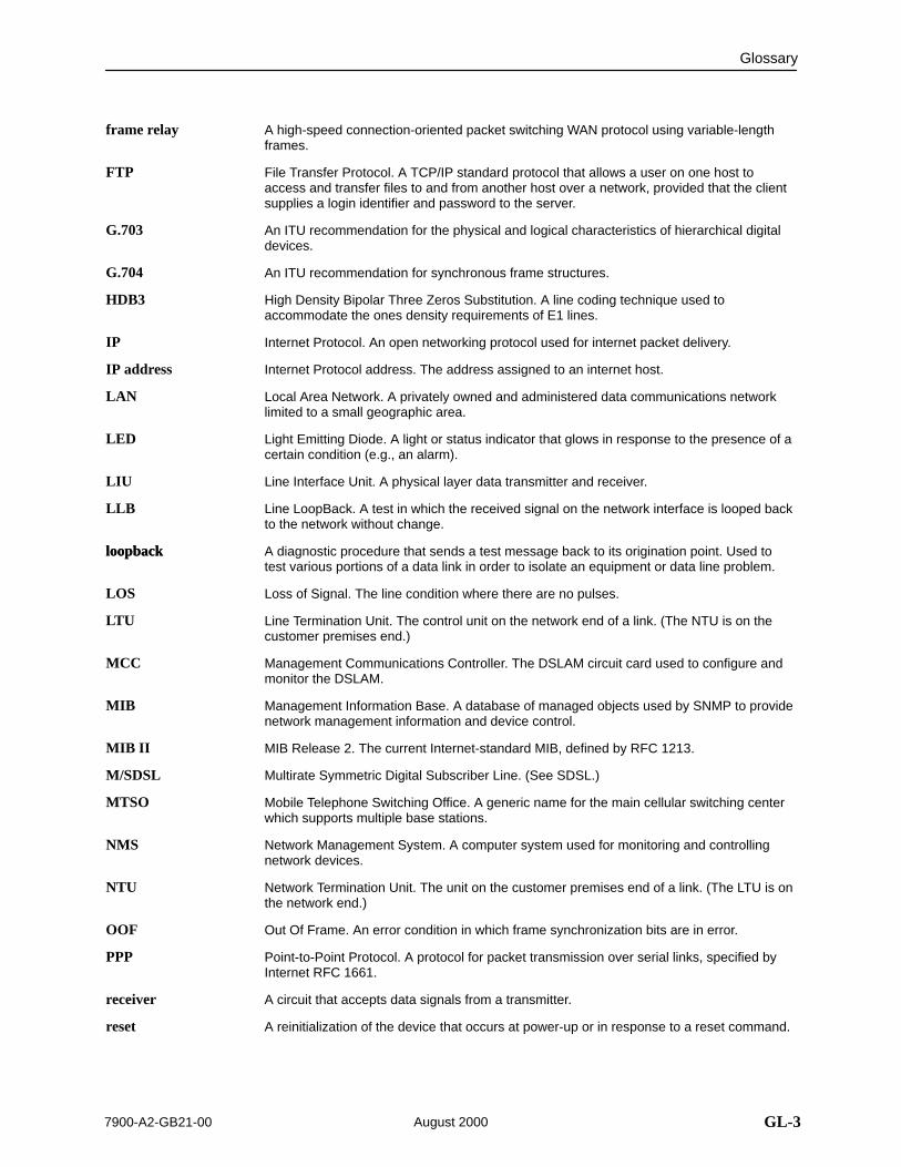
Glossary
GL-37900-A2-GB21-00 August 2000
A high-speed connection-oriented packet switching WAN protocol using variable-lengthframes.
File Transfer Protocol. A TCP/IP standard protocol that allows a user on one host toaccess and transfer files to and from another host over a network, provided that the clientsupplies a login identifier and password to the server.
An ITU recommendation for the physical and logical characteristics of hierarchical digitaldevices.
An ITU recommendation for synchronous frame structures.
High Density Bipolar Three Zeros Substitution. A line coding technique used toaccommodate the ones density requirements of E1 lines.
Internet Protocol. An open networking protocol used for internet packet delivery.
Internet Protocol address. The address assigned to an internet host.
Local Area Network. A privately owned and administered data communications networklimited to a small geographic area.
Light Emitting Diode. A light or status indicator that glows in response to the presence of acertain condition (e.g., an alarm).
Line Interface Unit. A physical layer data transmitter and receiver.
Line LoopBack. A test in which the received signal on the network interface is looped backto the network without change.
A diagnostic procedure that sends a test message back to its origination point. Used totest various portions of a data link in order to isolate an equipment or data line problem.
Loss of Signal. The line condition where there are no pulses.
Line Termination Unit. The control unit on the network end of a link. (The NTU is on thecustomer premises end.)
Management Communications Controller. The DSLAM circuit card used to configure andmonitor the DSLAM.
Management Information Base. A database of managed objects used by SNMP to providenetwork management information and device control.
MIB Release 2. The current Internet-standard MIB, defined by RFC 1213.
Multirate Symmetric Digital Subscriber Line. (See SDSL.)
Mobile Telephone Switching Office. A generic name for the main cellular switching centerwhich supports multiple base stations.
Network Management System. A computer system used for monitoring and controllingnetwork devices.
Network Termination Unit. The unit on the customer premises end of a link. (The LTU is onthe network end.)
Out Of Frame. An error condition in which frame synchronization bits are in error.
Point-to-Point Protocol. A protocol for packet transmission over serial links, specified byInternet RFC 1661.
A circuit that accepts data signals from a transmitter.
A reinitialization of the device that occurs at power-up or in response to a reset command.
frame relay
FTP
G.703
G.704
HDB3
IP
IP address
LAN
LED
LIU
LLB
loopbackloopback
LOS
LTU
MCC
MIB
MIB II
M/SDSL
MTSO
NMS
NTU
OOF
PPP
receiver
reset

Glossary
GL-4 7900-A2-GB21-00August 2000
Repeater LoopBack. Loops the signal being sent to the network back to the DTEDrop/Insert and data ports after it has passed through the framing circuitry of the device.
A device that connects LANs by dynamically routing data according to destination andavailable routes.
An Electronic Industries Association’s standard for a general-purpose, 37-position,DCE/DTE interface.
Request to Send. A signal from the DTE to the device, indicating that the DTE has data tosend. V.24 circuit 105.
Received Data. Pin 3 of the EIA-232 interface that is used by the DTE to receive data fromthe modem. Conversely, the modem uses Pin 3 to transmit data to the DTE.
Symmetric Digital Subscriber Line. A technique for the use of an existing twisted-pair linethat permits high bandwidth, bidirectional transmission.
Severely Errored Seconds. Usually defined as a second during which a specific number ofCRC errors was exceeded, or an OOF or other critical error occurred.
Simple Network Management Protocol. Protocol for open networking management.
A term for a digital carrier facility used to transmit a DS1 formatted digital signal at1.544 Mbps. It is used primarily in North America.
Transmission Control Protocol/Internet Protocol. The dominant protocol suite in theworldwide Internet, TCP allows a process on one machine to send data to a process onanother machine using the IP. TCP can be used as a full-duplex or one-way simplexconnection.
Virtual terminal protocol in the Internet suite of protocols. Allows the user of one hostcomputer to log into a remote host computer and interact as a normal terminal user for thathost.
Trivial File Transfer Protocol. A standard TCP/IP protocol that allows simple file transfer toand from a remote system without directory or file listing. TFTP is used where FTP is notavailable.
A circuit capable of acting as both a transmitter and a receiver.
A circuit capable of generating, modulating, and sending a signal for communication,control, and other purposes.
Transmit Data. Pin 2 of the EIA-232 interface that is used by the DTE to transmit data tothe modem. Conversely, the modem uses Pin 2 to receive data from the DTE.
An operating system developed at AT&T Bell Laboratories and since used as the basis ofsimilar operating systems.
An ITU-T standard for a high-speed, 34-position, DCE/DTE interface.
Wide Area Network. A network that spans a large geographic area.
An ITU-T standard for a high-speed, 15-position, DCE/DTE interface.
An outgoing signal transmitted when a DS1 or DS3 terminal has determined that it has lostthe incoming signal.
RLB
router
RS-449
RTS
RXD
SDSL
SES
SNMP
T1
TCP/IP
Telnet
TFTP
transceiver
transmitter
TXD
UNIX
V.35
WAN
X.21
Yellow Alarm

IN-17900-A2-GB21-00 August 2000
Index
AAbort All Tests, 8-2AC transformer, connecting, 3-2access
SNMP, 6-7to async terminal interface, 2-3
access levelCOM port, A-17Community Name 1, A-25Community Name 2, A-25effective, 6-2functions available for, 6-2NMS, A-27Telnet session, A-20
access to user interface, resetting/restoring, 6-6Action on Network LOS Alarm, A-10administer login, 6-3AIS (Alarm Indication Signal)
Send AIS on Network Failure option, A-7status message, 7-3
Alarm, LED, 7-18ASCII, printable characters, 3-5ATI (Asynchronous Terminal Interface)
access, 2-1defined, 1-2exiting, 2-8initiating session, 2-2virtual function keys, 2-7
authentificationFailure, B-2AutoRate, 3-16
ceiling, A-3ceiling (DSL Line Rate), A-3Network Interface Options screen, A-3resetting, 3-16switch setting
Models 7944, 7974, 7984, 4-5Models 7945, 7975, 7985, 4-8Models 7976 and 7986, 4-10
Ccables, C-1
COM Port Interface Cable, C-4COM Port to LAN Adapter Cable, C-5COM Port-to-PC cable, C-4, C-5DSL Network Interface Cable, C-14EIA-530-A-to-RS-449 Cable Interface, C-10EIA-530-A-to-X.21 Interface Cable, C-8part numbers, D-1pin Assignments, C-1
Card Failedself-test result, 7-5status message, 7-3
Circuit Identifier, A-4Clock Failed, status message, 7-4clocking
DSX-1 primary clock source, A-7G.703 primary clock source, A-12synchronous data port, A-9
COM portasynchronous terminal settings, 3-4Communication Port Options, A-15pinouts, C-3resetting, 6-6used with LAN Adapter, C-5
Communication Port Options, inactivity timeout, A-18Communication Protocol Options, A-21Community Name 1, A-25Community Name 2, A-25community names, for SNMP, 6-7Configurating AutoRate, 3-16

Index
IN-2 7900-A2-GB21-00August 2000
configurationaccessing configuration options, 3-8Communication Port Options, A-15Communication Protocol Options, A-21DSX-1 Interface Options, A-6editing and displaying options, 3-9example, 1-3G.703 Interface, A-11General SNMP Management Options, A-24loader, 3-11Management and Communication Options, A-19menu, 3-8network configuration examples, 1-7of the unit, 3-1option tables, A-1saving, 3-13SNMP Management, A-25SNMP NMS Security Options, A-26, A-27SNMP Traps Options, A-28SYNC Ports, A-8System Options, A-13Telnet Session Options, A-19using switches, 4-1
Configuration Mode, choosing an interface mode, 3-7connecting
to a system terminal, 3-4to the DSL network, 3-3to the DTE, 3-3
connectorsCOM Port, C-3EIA-530-A Port, C-7location on unit, 1-5rear panel, C-1
Control branchAdminister Logins, 6-3Change Identity, 3-5Download Code, 3-14Reset AutoRate, 3-16
CPU Fail, self-test result, 7-5create login ID, 6-3customer configuration, 3-7
switchpacks, internal switches, 4-2
Ddata channel loopback (DCLB), 8-11, A-10data port loopbacks, DTE initiated, A-10data terminal loopback (DTLB), 8-10, A-10DC power option, 3-2default configuration area, 3-7Default Network Destination, A-22delete, Login ID, 6-5device, messages, 7-7– 7-8Device Fail message, 7-19dimensions, D-1Disconnect Time, for Telnet session, A-18, A-20display, LED status, 7-17documents, related, viiiDOS, TFTP server on, 3-12download code, 3-14Download Failed, status message, 7-3DSL Line Rate
effect on AutoRate, A-3Network Interface Options screen, A-3switch setting
Models 7944, 7974, 7984, 4-5Models 7945, 7975, 7985, 4-8Models 7976 and 7986, 4-10
DSL line rateand payload rate, A-5AutoRate ceiling, A-3Fixed Rate, A-5
DSL Mode, A-13DSL Port, LEDs, 7-18DSLAM, defined, 1-2DSX-1
DTE Loopback, 8-8Interface Option settings, A-6LED, 7-18network interface pin assignments, C-6Network Repeater Loopback, 8-7
DSX-1 Failed, self-test result, 7-5DSX-1 Performance Statistics screen, 7-13DTE, connecting, 3-3DTE loopback
DSX-1, 8-8G.703, 8-15
DTE-initiated loopbacks, A-10
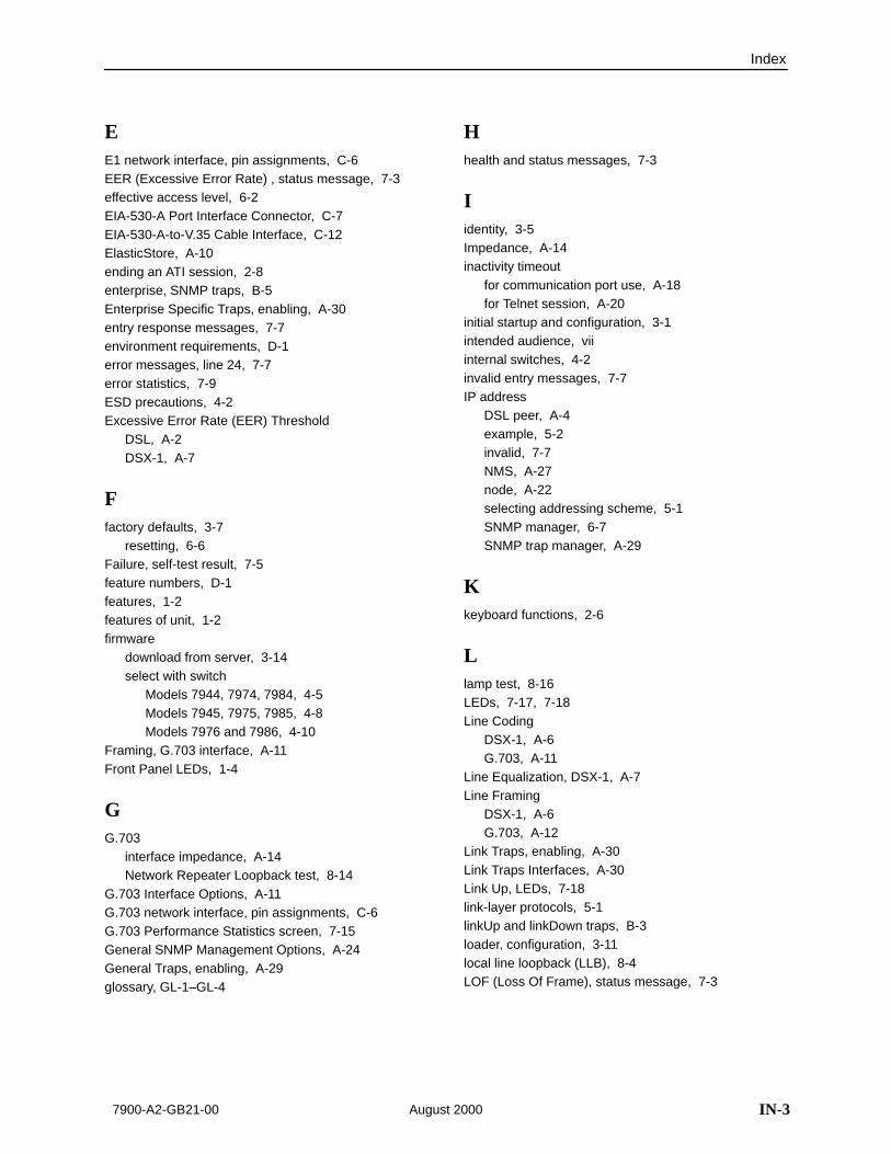
Index
IN-37900-A2-GB21-00 August 2000
EE1 network interface, pin assignments, C-6EER (Excessive Error Rate) , status message, 7-3effective access level, 6-2EIA-530-A Port Interface Connector, C-7EIA-530-A-to-V.35 Cable Interface, C-12ElasticStore, A-10ending an ATI session, 2-8enterprise, SNMP traps, B-5Enterprise Specific Traps, enabling, A-30entry response messages, 7-7environment requirements, D-1error messages, line 24, 7-7error statistics, 7-9ESD precautions, 4-2Excessive Error Rate (EER) Threshold
DSL, A-2DSX-1, A-7
Ffactory defaults, 3-7
resetting, 6-6Failure, self-test result, 7-5feature numbers, D-1features, 1-2features of unit, 1-2firmware
download from server, 3-14select with switch
Models 7944, 7974, 7984, 4-5Models 7945, 7975, 7985, 4-8Models 7976 and 7986, 4-10
Framing, G.703 interface, A-11Front Panel LEDs, 1-4
GG.703
interface impedance, A-14Network Repeater Loopback test, 8-14
G.703 Interface Options, A-11G.703 network interface, pin assignments, C-6G.703 Performance Statistics screen, 7-15General SNMP Management Options, A-24General Traps, enabling, A-29glossary, GL-1–GL-4
Hhealth and status messages, 7-3
Iidentity, 3-5Impedance, A-14inactivity timeout
for communication port use, A-18for Telnet session, A-20
initial startup and configuration, 3-1intended audience, viiinternal switches, 4-2invalid entry messages, 7-7IP address
DSL peer, A-4example, 5-2invalid, 7-7NMS, A-27node, A-22selecting addressing scheme, 5-1SNMP manager, 6-7SNMP trap manager, A-29
Kkeyboard functions, 2-6
Llamp test, 8-16LEDs, 7-17, 7-18Line Coding
DSX-1, A-6G.703, A-11
Line Equalization, DSX-1, A-7Line Framing
DSX-1, A-6G.703, A-12
Link Traps, enabling, A-30Link Traps Interfaces, A-30Link Up, LEDs, 7-18link-layer protocols, 5-1linkUp and linkDown traps, B-3loader, configuration, 3-11local line loopback (LLB), 8-4LOF (Loss Of Frame), status message, 7-3

Index
IN-4 7900-A2-GB21-00August 2000
Login ID, 6-1access levels, 6-2adding, 6-3deleting, 6-5invalid, 7-7
Login Required, enabling, A-17loopback, effect on LEDs, 7-18LOS (Loss Of Signal), status message, 7-3LOS alarm action, A-10LTU
NTU combinations supported, 1-3switch setting for
Models 7944, 7974, 7984, 4-5Models 7945, 7975, 7985, 4-8Models 7976 and 7986, 4-10
Mmain menu, 2-2, A-1Management and Communication Options, A-19management port
access, 6-1settings, 2-1
manual configuration, internal switches, 4-2Margin Threshold, A-2Max DSL AutoRate, A-3maximum payload rate, A-5Memory Fail, status, 7-5menu tree, 2-4messages
health and status, 7-3line 24, 7-7self-test results, 7-5test status, 7-6
MIBgeneral support, 1-6list of supported MIBs, 1-6
Mismatch Rate, Health and Status message, 7-4monitoring, 7-1
Nnavigating the screens, 2-6Net Margin Threshold, status message, 7-4network
configuration examples, 1-7destination, A-22DSL interface pin assignments, C-14interface options, A-2line loopback, 8-4Remote Send Line Loopback, 8-5T1/E1 network interface pin assignments, C-6tests, 8-3
Network Error Statistics screen, 7-9Network Interface Options, Transmit Attenuation, A-4Network Performance Statistics screen, 7-11Network-Initiated DCLB, A-10NMS
SNMP access, 6-7SNMP connectivity, 5-1SNMP NMS Security Options, A-26
no test active status message, 7-6Node IP Address, A-22Node Subnet Mask, A-22NTU
LTU combinations supported, 1-3switch setting for
Models 7944, 7974, 7984, 4-5Models 7945, 7975, 7985, 4-8Models 7976 and 7986, 4-10
NTU/LTU Mismatch, Health and Status message, 7-4Number of Trap Managers, A-29
OOK, LED, 7-18OOF (Out Of Frame), status message, 7-4options, configuration tables, A-1overview
features of unit, 1-2user’s guide, vii

Index
IN-57900-A2-GB21-00 August 2000
Ppart numbers, D-1Passed, self-test result, 7-5password, invalid, 7-7Payload Rate, A-9
Network Interface Options screen, A-3payload rate, relative to line rate, A-5PC
connecting, 3-4requirements, 3-4
Peer IP Address, A-4performance statistics, 7-11
DSX-1, 7-13G.703, 7-15
physical environment requirements, D-1pin assignments, C-1port
COM port interface cable, C-4COM port LAN Adapter cable, C-5COM port pinouts, C-3
Port Access Level, A-17Port Type, A-8power, problems, 7-19power cord installation, 3-2power input
connector, C-2– C-14optional power sources, C-2– C-14
power requirements, D-1power supply
AC transformer, 3-2optional dc, 3-2– 3-16
Primary Clock SourceDSX-1, A-7G.703, A-12
Rrear panel, 1-5related documents, viiiRemote Telco Line Loopback, A-14repeater loopback (RLB), 8-7resetting
AutoRate, 3-16COM port settings, 6-6factory defaults, 6-6the access unit, COM port, 6-6
restoring, user interface access, 6-6RS-449 interface, C-11
SSave Configuration screen, 3-13saving configuration options, 3-13screen, function keys, 2-7screen summary, 2-4screens, for user interface, 2-1– 2-6security, 6-1Selectable Payload Rates, switch settings, 4-7self-test results, 7-5Send (AIS) on Network Failure
enabling for DSX-1, A-7enabling for G.703, A-12
Send and Monitor 511, 8-3Send Ones configuration option, A-9Send Remote DCLB Loopback, 8-12Session Access Level, A-20size of unit, D-1SNMP
configuration examples, 1-7general capabilities, 1-6general management options, A-25General SNMP Management Options, A-24limiting access, 6-7NMS IP Address, A-27NMS Security Options, A-26, A-27trap support, 1-7traps, B-1Traps Options, A-28
standalone-to-standalone configurations, supported,1-3
start-up, ATI, 2-1status, test messages, 7-6Status branch
Display LEDs, 7-17DSX-1 Performance Statistics, 7-13G.703 Performance Statistics, 7-15Network Error Statistics, 7-9Network Performance Statistics, 7-11System and Test Status, 7-2
subnet, IP addresses, 5-1switchpacks
configuration using, 4-1definitions
Models 7944, 7974, 7984, 4-4Models 7945, 7975, 7985, 4-6Models 7976 and 7986, 4-9
enabling and disablingModels 7944, 7974, 7984, 4-4Models 7945, 7975, 7985, 4-6Models 7976 and 7986, 4-9
location, 4-3

Index
IN-6 7900-A2-GB21-00August 2000
SYNC Ports Options, A-8SYNC Pt Down, status message, 7-4system, LEDs, 7-18System and Test Status screen, 7-2System Options, A-13
TT1 network interface, pin assignments, C-6Telco-initiated
line loopback, 8-18loopback, enable/disable, A-14payload loopback, 8-19remote line loopback, 8-19
Telnet sessionaccess, 6-1access level, A-20enable/disable, A-20inactivity timeout, A-20login required, A-20options, A-19
terminalcommunication parameters, 3-4connecting, 3-4settings required, 3-4
terminal port, direct connection, 2-1test
aborting, 8-17Data Channel Loopback, 8-11Data Terminal Loopback, 8-10DTE Loopback
DSX-1, 8-8G.703, 8-15
LED, 7-18Line Loopback, 8-4menu, 8-1, 8-13Network Repeater Loopback (DSX-1), 8-7Network Repeater Loopback (G.703), 8-14Network-Initiated DCLB, A-10Port (DTE) Initiated Loopbacks, A-10Remote Send Line Loopback, 8-5status messages, 7-6switch setting for telco loopback, 4-5switch setting for telco remote loopback, 4-5Telco-initiated, 8-18terminating, 8-17Test Duration, A-13Test Timeout, A-13
Time Slot16, configuration option, A-12time slots, relative to payload rate, A-5timeout
Com port session inactivity, A-18for tests, A-13Telnet session inactivity, A-20
timingDSX-1 primary clock source, A-7G.703 primary clock source, A-12synchronous data port, A-9
Transmit Attenuation, A-4transmit clock source, A-9traps
SNMP, B-1, B-2support of, 1-7
troubleshooting, 7-19DSL performance statistics, 7-11DSX-1 performance statistics, 7-13error statistics, 7-9G.703 performance statistics, 7-15
UUNIX, TFTP server on, 3-12user interface, 3-4
async terminal, 2-1how to access, 2-1resetting/restoring access, 6-6
VV.35 interface, C-13V.54 Loop 3. See data terminal loopback (DTLB)virtual function keys, 2-7
WwarmStart, B-2weight of unit, D-1