how electric motors works
TRANSCRIPT
8/2/2019 How Electric Motors Works
http://slidepdf.com/reader/full/how-electric-motors-works 1/8
How Electric Motors Works
Much has been written about choosing the right motor, estimating performance, installing the motor in your
plane, and so on. This month, I've decided to go back to basics and describe how the motor actually works. Doyou need to know this to fly electric models? Probably not, but a good understanding of the functioning of a
motor can help you diagnose problems. And some people, myself included, like to know how everything works.
So, if you're interested, read on!
I'm going to start with the very basics, so if you already know some of it, feel free to skip ahead. I won't beoffended.
MagnetsThe fundamental driving force behind all electric motors, whether brushed or brushless, AC or DC, ismagnetism. We've probably all played with magnets at some time or other, and have learned about them in
science class in elementary school.
Recall that any magnet has a north pole and a south pole (it just so happens that the earth is a magnet whosepoles happen to correspond very roughly to the geographical poles, hence the names for the magnet's poles). If
you take two bar shaped magnets and line them up, they will be attracted to one another if one's north pole is
next to the other's south pole. If you line them up north to north or south to south, they will repel each other.
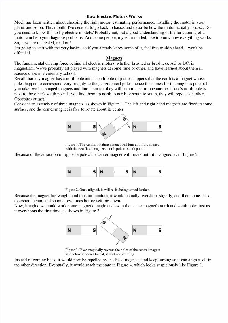
Opposites attract.Consider an assembly of three magnets, as shown in Figure 1. The left and right hand magnets are fixed to some
surface, and the center magnet is free to rotate about its center.
Figure 1. The central rotating magnet will turn until it is aligned
with the two fixed magnets, north pole to south pole.
Because of the attraction of opposite poles, the center magnet will rotate until it is aligned as in Figure 2.
Figure 2. Once aligned, it will resist being turned further.
Because the magnet has weight, and thus momentum, it would actually overshoot slightly, and then come back,overshoot again, and so on a few times before settling down.
Now, imagine we could work some magnetic magic and swap the center magnet's north and south poles just as
it overshoots the first time, as shown in Figure 3.
Figure 3. If we magically reverse the poles of the central magnet
just before it comes to rest, it will keep turning.
Instead of coming back, it would now be repelled by the fixed magnets, and keep turning so it can align itself inthe other direction. Eventually, it would reach the state in Figure 4, which looks suspiciously like Figure 1.

8/2/2019 How Electric Motors Works
http://slidepdf.com/reader/full/how-electric-motors-works 2/8
Figure 4. Eventually, it will get back into the position it started
from in Figure 1.
If we perform this pole-swapping every time the center magnet just finishes overshooting the aligned position, itwould keep turning forever.The problem is how to perform this feat of magnetic motion.
ElectromagnetsThe magnets we play with are called permanent magnets. These objects have a fixed magnetic field that's
always there. The poles are fixed relative to one another and relative to the physical magnet.Another kind of magnet is the electromagnet. In its simplest form, this consists of an iron bar, wrapped in a coil
of wire, as in Figure 5.
Figure 5. An electromagnet is just a piece
of iron or other magnetic metal with a
wire coil wrapped around it.
By itself it does nothing. However, if you pass an electric current through the wire, a magnetic field is formed in
the iron bar, and it becomes a magnet, as in Figure 6.
Figure 6. Applying current in one
direction will produce a magnet.
If you turn off the current, it stops being a magnet (that's a bit of a simplification, since in reality, it ends up
remaining a weak magnet, but we needn't concern ourselves with that for the moment).
So far, the electromagnet already seems quite useful, since we can use it to pick up iron, steel, or nickel objects,
carry them somewhere, and then drop them by just turning off the power (wrecking yard cranes do this with
entire automobiles).The really interesting thing about an electromagnet is that its polarity (the location of the north and south poles)
depends on the direction of current flow. If we pass the current through in the opposite direction, theelectromagnet's poles will be reversed, as shown in Figure 7.

8/2/2019 How Electric Motors Works
http://slidepdf.com/reader/full/how-electric-motors-works 3/8
Figure 7. Applying current in the opposite
direction will produce a magnet with
opposite polarity.
Eureka!
If we replace the central magnet in our set of three magnets with an electromagnet, as in Figure 8, we have thebeginnings of an electric motor.
Figure 8. Replacing the central magnet in Figure 1 with an
electromagnet gives us the beginnings of a motor. Click to
enlarge.
Now we have two problems to solve: feeding the current to the rotating electromagnet without the wires getting
twisted, and changing the direction of the current at the appropriate time.Both of these problems are solved using two devices: a split-ring commutator, and a pair of brushes. Figure 9
illustrates these.
Figure 9. By adding a commutator (the semi-circular arcs) and
brushes (the wide arrows), we can change the polarity of the
electromagnet as it turns. Click to enlarge.
The two semicircles are the commutator, and the two arrows are the brushes. The current is applied to the
brushes, indicated by the "+" and "-" signs.
With the current as shown, the electromagnet will be repelled by the two permanent magnets, and it will turn
clockwise. After it has turned almost half way around, it will be in the state shown in Figure 10.
Figure 10. The magnets are almost aligned, but soon, the polarity
will reverse, sending the rotating electromagnet on its way
around once again. Click to enlarge.
8/2/2019 How Electric Motors Works
http://slidepdf.com/reader/full/how-electric-motors-works 4/8
Then, just as the magnet reaches the aligned state, the split in the commutator passes under the brushes, andthen the current through the electromagnet reverses, which takes us back to the condition in Figure 9. As a
result, the magnet keeps turning. We have a motor!
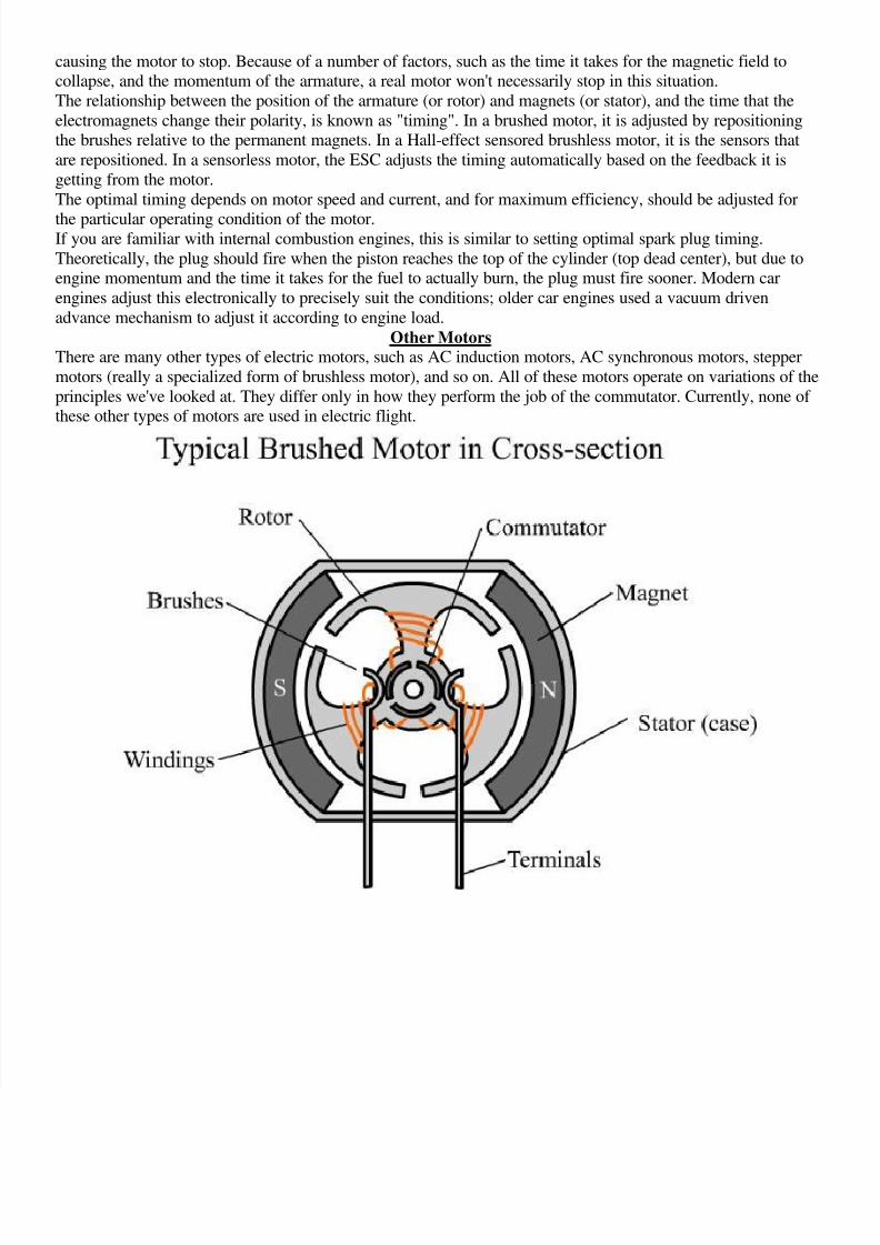
Some TerminologyThe discussion above has culminated in the design of a simple two-pole, two-slot, permanent magnet, brushed,
direct-current (DC) motor.
The term two-pole refers to the fact that there are two permanent magnet poles involved in the operation of the
motor, the south pole of the left hand magnet and the north pole of the right hand magnet. The motor would
actually work with only one fixed magnet (for example, only the left hand magnet), but would be less powerfuland efficient.
The rotating electromagnet is known as the armature. Two-slot means that the armature consists of a single coilof wire around a single bar with only two ends (the term "slot" refers to the gap between the armature ends,
since the armature is not typically bar shaped, but has a wider end).
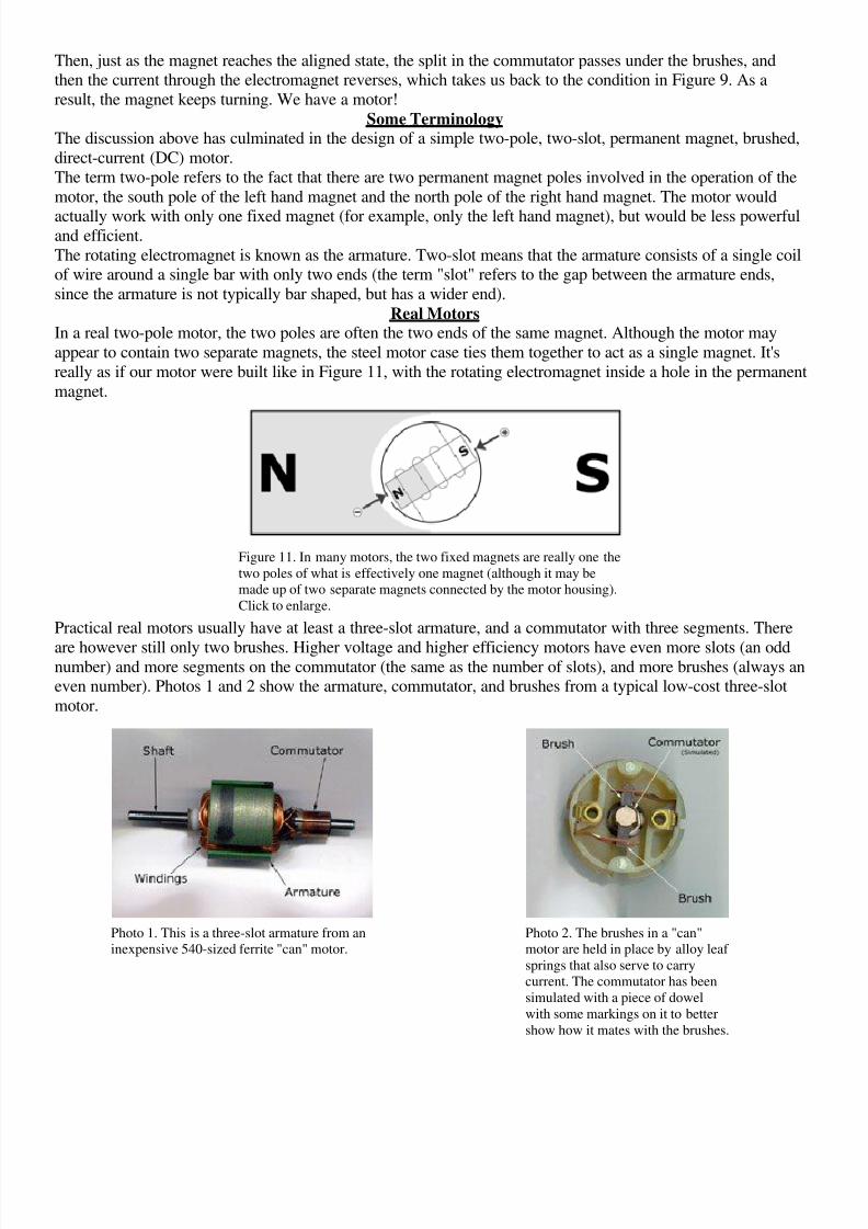
Real MotorsIn a real two-pole motor, the two poles are often the two ends of the same magnet. Although the motor may
appear to contain two separate magnets, the steel motor case ties them together to act as a single magnet. It's
really as if our motor were built like in Figure 11, with the rotating electromagnet inside a hole in the permanent
magnet.
Figure 11. In many motors, the two fixed magnets are really one the
two poles of what is effectively one magnet (although it may be
made up of two separate magnets connected by the motor housing).
Click to enlarge.
Practical real motors usually have at least a three-slot armature, and a commutator with three segments. There
are however still only two brushes. Higher voltage and higher efficiency motors have even more slots (an oddnumber) and more segments on the commutator (the same as the number of slots), and more brushes (always aneven number). Photos 1 and 2 show the armature, commutator, and brushes from a typical low-cost three-slot
motor.
Photo 1. This is a three-slot armature from an
inexpensive 540-sized ferrite "can" motor.
Photo 2. The brushes in a "can"
motor are held in place by alloy leaf
springs that also serve to carry
current. The commutator has been
simulated with a piece of dowel
with some markings on it to better
show how it mates with the brushes.

8/2/2019 How Electric Motors Works
http://slidepdf.com/reader/full/how-electric-motors-works 5/8
Figure 12 illustrates a three-slot motor in conceptual form. Notice that the brush is now wider, contacting thecommutator segments over a wider area, and actually spanning two segments sometimes.
Figure 12. This is a schematic representation of a typical three-slot two-pole brushed
motor. The armature has three electromagnets, and three commutator segments. The
brushes sometimes contact more than one segment. Click to enlarge.
Also notice that both ends of electromagnet number 2 are contacting the "-" brush at the particular point in time
captured by Figure 12. This means that no current is flowing through electromagnet 2, and only number 1 and 3are on.Effectively, the armature is now a pair of electromagnets; number 3 is being attracted by the north pole of the
right hand permanent magnet, and number 1 is being repelled.
One twelfth of a turn later, as in Figure 13, all three electromagnets have current flowing through them.
Figure 13. The same motor as in Figure 12, one twelfth of a rotation (30 degrees) later.
Click to enlarge.
Now, electromagnet number 1 is being both repelled by the right hand permanent magnet, and attracted by the
left hand one. Number 2 is being repelled by the left magnet, and number 3 is still being attracted by the right
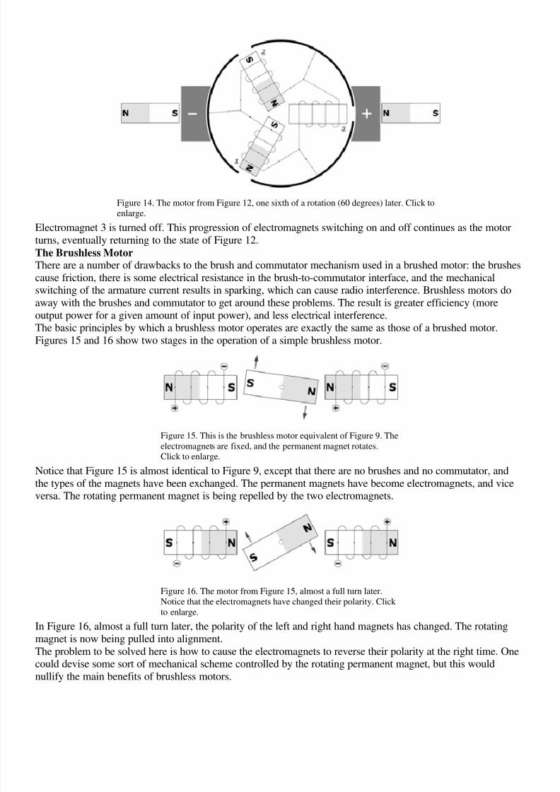
magnet.Another twelfth of a turn later, in Figure 14, electromagnet 1 is being attracted to the left hand magnet, andnumber 2 is still being repelled.
8/2/2019 How Electric Motors Works
http://slidepdf.com/reader/full/how-electric-motors-works 6/8
Figure 14. The motor from Figure 12, one sixth of a rotation (60 degrees) later. Click to
enlarge.
Electromagnet 3 is turned off. This progression of electromagnets switching on and off continues as the motor
turns, eventually returning to the state of Figure 12.
The Brushless MotorThere are a number of drawbacks to the brush and commutator mechanism used in a brushed motor: the brushes
cause friction, there is some electrical resistance in the brush-to-commutator interface, and the mechanicalswitching of the armature current results in sparking, which can cause radio interference. Brushless motors do
away with the brushes and commutator to get around these problems. The result is greater efficiency (more
output power for a given amount of input power), and less electrical interference.The basic principles by which a brushless motor operates are exactly the same as those of a brushed motor.
Figures 15 and 16 show two stages in the operation of a simple brushless motor.
Figure 15. This is the brushless motor equivalent of Figure 9. The
electromagnets are fixed, and the permanent magnet rotates.
Click to enlarge.
Notice that Figure 15 is almost identical to Figure 9, except that there are no brushes and no commutator, and
the types of the magnets have been exchanged. The permanent magnets have become electromagnets, and viceversa. The rotating permanent magnet is being repelled by the two electromagnets.
Figure 16. The motor from Figure 15, almost a full turn later.
Notice that the electromagnets have changed their polarity. Click
to enlarge.
In Figure 16, almost a full turn later, the polarity of the left and right hand magnets has changed. The rotating
magnet is now being pulled into alignment.
The problem to be solved here is how to cause the electromagnets to reverse their polarity at the right time. Onecould devise some sort of mechanical scheme controlled by the rotating permanent magnet, but this would
nullify the main benefits of brushless motors.
8/2/2019 How Electric Motors Works
http://slidepdf.com/reader/full/how-electric-motors-works 7/8
Instead, the electromagnets are controlled by external circuitry. This circuitry monitors the current position of the rotating magnet, and energizes the external magnets appropriately to keep the motor turning. This circuitry
is part of the brushless electronic speed control (ESC).
There are two ways for a brushless ESC to monitor the position of the rotating magnet. One is by way of magnetic sensors (based on the Hall-effect). These sensors report back to the ESC through a separate set of
wires. The other method is known as "sensorless". Roughly, in this method the ESC monitors the three motor
power wires for fluctuations caused by the spinning magnets.
Brushless Terminology
Since the electromagnet assembly in a brushless motor remains stationary, it is called a stator instead of anarmature. The rotating magnet assembly is called the rotor.
Real Brushless MotorsJust as a real brushed motor rarely has only two poles and a two-slot armature, a real brushless motor rarely has
only a two-pole rotor and a two-slot stator. Most commercially available brushless motors have at least four
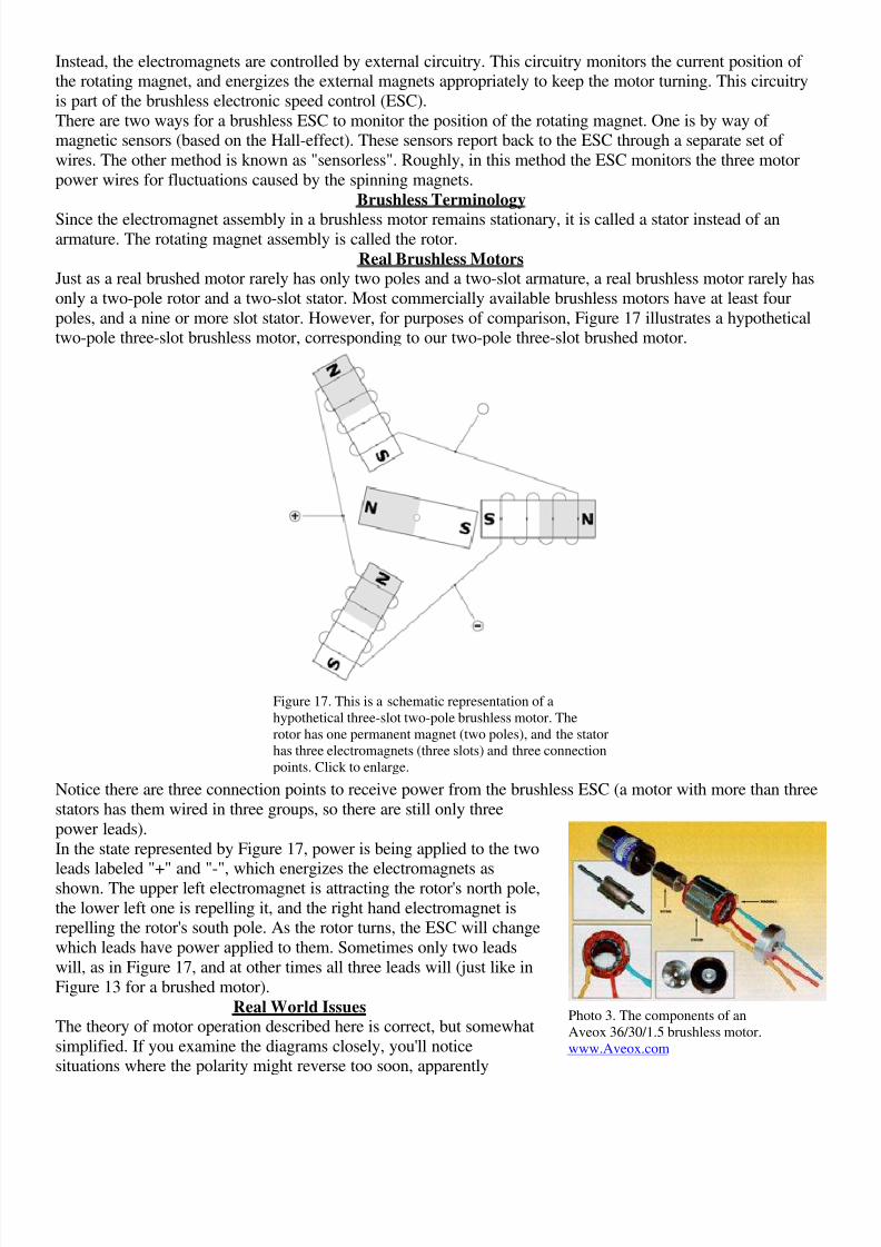
poles, and a nine or more slot stator. However, for purposes of comparison, Figure 17 illustrates a hypotheticaltwo-pole three-slot brushless motor, corresponding to our two-pole three-slot brushed motor.
Figure 17. This is a schematic representation of a
hypothetical three-slot two-pole brushless motor. The
rotor has one permanent magnet (two poles), and the stator
has three electromagnets (three slots) and three connection
points. Click to enlarge.
Notice there are three connection points to receive power from the brushless ESC (a motor with more than three
stators has them wired in three groups, so there are still only three
power leads).
In the state represented by Figure 17, power is being applied to the two
leads labeled "+" and "-", which energizes the electromagnets asshown. The upper left electromagnet is attracting the rotor's north pole,
the lower left one is repelling it, and the right hand electromagnet isrepelling the rotor's south pole. As the rotor turns, the ESC will change
which leads have power applied to them. Sometimes only two leads
will, as in Figure 17, and at other times all three leads will (just like in
Figure 13 for a brushed motor).
Real World IssuesThe theory of motor operation described here is correct, but somewhat
simplified. If you examine the diagrams closely, you'll noticesituations where the polarity might reverse too soon, apparently
Photo 3. The components of an
Aveox 36/30/1.5 brushless motor.
www.Aveox.com
8/2/2019 How Electric Motors Works
http://slidepdf.com/reader/full/how-electric-motors-works 8/8
causing the motor to stop. Because of a number of factors, such as the time it takes for the magnetic field tocollapse, and the momentum of the armature, a real motor won't necessarily stop in this situation.
The relationship between the position of the armature (or rotor) and magnets (or stator), and the time that the
electromagnets change their polarity, is known as "timing". In a brushed motor, it is adjusted by repositioningthe brushes relative to the permanent magnets. In a Hall-effect sensored brushless motor, it is the sensors that
are repositioned. In a sensorless motor, the ESC adjusts the timing automatically based on the feedback it is
getting from the motor.
The optimal timing depends on motor speed and current, and for maximum efficiency, should be adjusted for
the particular operating condition of the motor.If you are familiar with internal combustion engines, this is similar to setting optimal spark plug timing.
Theoretically, the plug should fire when the piston reaches the top of the cylinder (top dead center), but due toengine momentum and the time it takes for the fuel to actually burn, the plug must fire sooner. Modern car
engines adjust this electronically to precisely suit the conditions; older car engines used a vacuum driven
advance mechanism to adjust it according to engine load.
Other MotorsThere are many other types of electric motors, such as AC induction motors, AC synchronous motors, stepper
motors (really a specialized form of brushless motor), and so on. All of these motors operate on variations of the
principles we've looked at. They differ only in how they perform the job of the commutator. Currently, none of these other types of motors are used in electric flight.