how much 1gh tension? -...
TRANSCRIPT

PRACTICAL WIRELESS, May 2515, MO.
HOW MUCH 1GH TENSION?_
A
NEWNES
PUBLICATION
E,ctita
ICAM MVol. 16. No. 401.
111111116
3 D
EVERY
WEDNESDAYMay 25th, 1940.
A- PRACTICAL TELEVISION *
eantazAite.The Amateurs'
Activities
Alternating CurrentCircuits
O
Thermion'sCommentary
O
Is Full -wave DetectionImpossible ?
Practical Hints
Using a Short-waveConverter
How Much HighTension?
British Long-distanceListeners' Club
Readers' Letters
832pages
Over
500illustrations
Covers the whole theory and practice of Wireless Reception
THE OUTLINE OF WIRELESSDeals with Matter and Energy, Electrified Matter, Elect milk Contents, NIngoe I kin :not Yleetro-Maciteli.to lett terie.and Accumulators, Wireless Communication and Broadcasting, Almicin %oho,. 1111 cies, Signals, 1,N ircicss Beech IneCircuits, Wireless Aleasuring instruments, etc.From all Booksellers, or by post 11/- from GEORGE NEWNES, LTD. (Book Dept.), roue(' Muse, Southampton Sired, I Pr 4, I f
nyRALPH
STRANGER
1016

PRACTICAL WIRELESS May 25th, 1940
NEW SERIES
RADIO ENGINEER'S POCKET BOOKNo. 113.
FORCEThe absolute unit of force is the Poundal,
which is that force, acting for unit time,which would impart unit velocity to unitmass.
1 dyne =0.00007233 poundal.1 dyne =0.00102 gram.1 dyne =22.48 x 10⁷ pounds.1 megadyne 1,000,000 dynes.1 poundal -=13,825 dynes.,1 poundal =0.03108 pound.l poundal =14.10 grams.
1 erg =7.376 Xpounds.
1 g.em. =7.233 X 10⁻⁵ footpounds.
1 joule =107 ergs.1 foot poundal =421.390 ergs.1 foot pound =1.35573 joules...1 foot pound =13,825.5 g.cm.The actual energy, Kinetic, energy,
or dynamic energy of a moving body-A- mass x velocity 2.
ENERGYEnergy refers to capacity for performing
work, for moving against a resistance.1 erg =2.373 x 10⁻⁶ foot
poundals.108 foot
No. 116.
ENGLISH WEIGHTS & MEASURESLONG MEASURE
12 inches (in.) =3 feet =--
51 yards.40 poles (220
yards)8 furlongs (1,760
yards)3 miles1 chain10 chains6 feet6,080 feet per
hour4 inches
1 foot (ft.)1 yard (yd.)1 rod, pole or perch
1 furlong (furl.)
1 mile (In.)=1 league
100 links (22 yards)-1 furlong1 fathom
1 knot1 hand
AREA (Square Measure)144 square inches -1 square foot.9 square feet =1 square yard30.1 square yards -=1 square pole40 square poles =1 rood4 roods . - =1 acre (4,840
square yards)640 acres =1, square mile
MEASURES OF VOLUME AND CAPACITY(Cubic Measure)
1,728 cubic inches= 1 cubic foot.27 cubic feet =1 cubic yard1 marine ton =40 cubic feet1 stack =108 cubic feet1 cord =128 cubic feet
No. 114.
1
,1I
1
1
1
1
1
11
POWERwatt =107 ergs per second.watt =23.731 foot pound-
als per sec.watt =0.7376 foot lb. per
second.watt =0.001341 h.p.kilowatt-hour =2.654,200 f o o t
pounds.kilowatt-hour =1.3411 h.p. hour.kilowatt-hour =859.975 calories.foot poundal per =421.390 ergs persecond secondfoot poundal persecond =1.35573 watts.horse -powerhorse -power
1 horse -power
=746 watts.=550 foot pounds per
second.-178.122 calories per
second.
ELECTRICAL EQUATIONSAmperes x voltsJoules 2:- secondsCoulombs per
secondWatts 746Coulombs volts0.7373 foot -lb. pet
secondVoltS x coulombsWatts x 44.236Kilowatts x 1.34
=watts.=watts.
=amperes.=effective h.p.=farads.
,
=1 joule.-joules.=foot -lb. per minute.= h.p.
No. 117.
MEASURE OF CAPACITY(Liquid or Dry Measure)
4 gills2 pints2 quarts2 potties4 quarts2 gallons4 peeks8 bushels
12 bags5 quarters2 loads
Wine2 pints4 quarts
10 gallons18 gallons42 gallons2 tierces1 puneheons2 pipes
Ale and;4. gillS2 pints4 quarts9 gallons2 firkins2 kilderkins11- barrels1 hogshead1-puheheous
==j pint=1 quart,=1 pottle=1 gallon=1 gallon=1 peck=1 bushel=1 quarter=1 chau lam=1 load=1 lastMeasure=1 quart=1 gallon=1 anker=1 runlet or rundlet=1 tierce=1 puncheon=1 pipe or butt=1 tun
Beer Measure=1 pint=1 quart=1 gallon=1 firkin=1 kilderkin=1 barrel=1 hogshead=1 puncheon=1 butt or pipe
No. 115.
HEATA therm is the heat equivalent of an erg
on the G.G.S. system.The Centigrade Heat Unit (C.H.U.)
is the heat required to raise llb. water 1°C.A calorie as used in engineering cal-
culations represents the heat required toraise 1 kilogramme of pure water 1°C.This if, the Great Calorie. The SmallCalorie represents the heat required toraise 1 gramme of water 1°C.
1
1
1
1
1
calorie (g.c.)=0.0039683 B.T.U.calorie (g.c.)=4.1862 joules.caloric (g.c.) =3.088 foot lb.calorie (g. c.) =0.005614 horse -powersecond.B.T.U. =252.00 calories.B.T.U. =1,005 joules.B.T.U. ==778.1 foot lb.B.T.U. -1.4147 horse -power second.C.H.U. =1.8 B.T.U.
TIME1 sidereal second=0.99727 - second
(mean solar).1 second (mean solar) =1.002738
sidereal second.Length of seconds pendulum latitude
45°= 39.1163 in. 99.3555 cm.
No. 118.
Avoirdupois Weight27.34375 grains =1 dram -16 drams =1 ounce16 ounces -1 pound (lb.)14 pounds =1 stone2 stone (28 lb.) =1 quarter4 quarters =lhundredWeight(ewt.)20 cwt. =1 ton100 lbs. =1 rental
Apothecaries Weight20 grains =1 scruple3 scruples =1 drachm8 drachms =1 ounce -
12 ounces =1 poundApothecaries' Fluid Measure
60 minims =I fluid drachmS drachms =1 fluid ounce
20 ounces =1 pint8 pints =1 gallon
Diamond and Pearl Weight3.17 grains =1 carat, or4 pearl grains =1 carat151.? carats =1 ounce (troy)
Paper Measure24 sheets =1 quire20 quires =1 ream2 reams " =1 bundlelOreams =1 bale
Troy Weight3.17 grains =1 carat24 grains =1 pennyweight (dwt.)20 pennyweights= 1 ounce12 ounces =1 pound1 lb. =5,760 grains1 lb. avoir. =7,000 grains
(See also page 223.)

May 25th, 1940 PRACTICAL- WIRELESS
PRACTICA.LEVERY WEDNESDAY
Val. XVI. No. 401. May 25th, 1940.
TELEVISION *
EOITE 0 BYI. J.CANINI
209
Staff :W. J. DELANEY, FRANK PRESTON.
H. J. BARTON CHAPPLE, B.Sc.
ROUND THE WORLD OF WIRELESSYour Copy of the
RADIO TRAINING MANUALTHE demand for this great new work,
offered recently in " PracticalWireless," has been exceptional andorders are being dealt with as quickly asthe presses can complete copies. In war-time, however, delays occur which areunavoidable, and if you do not receiveyour copy within the nextfew days, pleasedo not make enquiries. Rest assuredyour order is in hand and that your copywill be posted to you the moment it isready.
Summer -time ConditionsA LTHOTJGH most listening is carried
Pl. out in the winter months, the mostinteresting long-distance work may bedone in the summer. During the darknights signals travel much easier, and manylisteners are finding that with the approachof the long hours of sunlight signals arenot so easily heard. Consequently thereceiver must be more accurately handled,or improvements must be effected to ensurethat the weak signals are picked up. Inthis issue we give details of some of thepoints which should be attended to inorder to improve the performance of theraceiver for the conditions_ which will soonbe obtaining, and in many-bther directionsthe keen listener will take steps to makesure that he can get the best from his set.It is, of course, just as necessary to make asimilar type of overhaul at the end of thesummer in order that the apparatus willweather the wintry conditions and willnot need attention until the followingsummer.
Midlands v. Wales in DartsCHARLIE GARNER will be the
commentator when the Inter -Regional Darts Match, Midlands v. Wales,is broadcast before an audience of troops inone of the Midland Counties on.May 27th.The two teams are Cider Mill from Hampton,near Evesham, representing the Midlands,and Rhayader, representing Wales.
Rugby League CommentaryALTHOUGH war -time sport is not
on the usual big scale, listeners tosports commentaries will hear at least onefootball final. Arrangements are nowbeing made for a commentary on thesecond half of the match for deciding theRugby League war -time chainpionshipin the North. Lance B. Todd will give thecommentary, which will be broadcast inthe Home Service programme and forlisteners to the Forces programme.
Double Bill ProgrammeADOUBLE bill comes from the North
on May 25th, when Cecil McGivern
Flanagan and Allen, popular members of the -
Crazy Gang, who, as mentioned in the third column,will be heard on the air this week. Ben Lyon and
Bebe Daniels are in the centre.
Editorial and Advertisement Offices" Practical Wireless," George Newnes, Ltd.,
I Tower House, Southampton Street, Strand,W.C.2. 'Phone : Temple Bar 4363.
Telegrams :. Newnes, Rand, London.Registered at the G.P.O. as a newspaper andfor transmission by Canadian Magazine Post. t
The Editor will be pleased to consider articles of apractical nature suitable for publication in f,PRACTICAL WIRELESS. Suck articles' should be !written on one side of the paper only, and shouldcontain the name and address of the sender. T1
the Editor does not hold himself responsible formanuscripts, every effort will be made to returnthem if a stamped and addressed envelope isenclosed. All correspondence intended for theEditor should be addressed: The Editor, PRACTICALWIRELESS, George Eames, Ltd., Tower house,Southampton Street, Strand, W.C.2.
Owing to the rapid progress in the design ofwireless apparatus and to our efforts to keep ourreaders ,n touch with the latest developments, we give tno warranty_ that apparatus described in ourcolumns is not the subject of letters patent.
Copyright in all draWings, photographs andarticles published in PRACTICAL WIRELESS is 4
specifically reserved throughout the countries signa-tory to the Berne Convention and the U.S.A.Reproductions or imitations of any of these aretherefore expressly forbidden. PRACTICAL WIRE-LESS incorporates Amateur Wireless.".
7
will produce " Call for an Author," byLyn Durham, and " Big Moment ", byNorman Holland, in the Home Serviceprogramme. The name of Lyn Durhamhides the identity of a Gateshead school-master who has w itten several plays,some of which have been broadcast."-Call. for an Anther " is the story of aman masquerading as a playwright whosework he has stolen. " Big Moment 7 a storyof the ring, concerns a boxer who bankseverything on his Just fight for a wordchampionship. He wins the coveted cham-pionship but at a terrible price, which isrevealed at the end of this exciting littleplay.,
Flanagan and AllenTHEgreat success of ithe famous London
Palladium Crazy Shows, which havenow been running for several years, has -been mainly responsible for keeping offthe air those master buffoons and mainstaysof the Crazy Gang, Flanagan and Allen.Now they are going to snake up for losttime by giving four broadcasts betweenMay 25th and May 31st. On May 25th theywill be heard from the Hippodrome,Birmingham, in " Youth Takes a Ben, " ;on May 27th in the Forces Programmeseries called " Top of the Bill " ; onMay 30th in a revue to be produced by
' Tom Ronald ; and on May 31st in cabaretfrom the Grand Hotel, Torquay.
"Melody and Co."JIMMY O'DEA, the popular Irish come-
dian, is to star in a new series called" Melody and Co," devised by VernonHarris and Eric Spear, which is to beginon May 23rd. " Melody and Co." is the namegiven to a struggling road -show of whichJimmy is the principal comedian, whoseever-changing fortuneS listeners will beable to follow from week to week. Othersin the cast will be Jack Melford, the well-known light comedian, who has recentlybeen appearing in " The Silver Patrol "Marion Wilson, from " The Little DogLaughed " ; Patricia Leonard, JacquesBrown"and Sam Costa,
Harry O'Donovan and Aubrey Danvers -Walker will be responsible for the dialogue.Twelve years ago, Harry O'DonoVan andJimmy O'Dea, who had met way back in1919, founded a partnership which wasto be a great success. Their road shows,mainly written by O'Donovan, have beenfavourites with North of England andScottish audiences for many years past.Eric Spear will be responsible for the musicof " Melody and Co. and Vernon Harriswill produce.
210 PRACTICAL WIRELESS
'[H AMATIM S' ACTIVITIHow to Obtain the Greatest Interest Outof Your Station is Discussed in This Article
By L. O. SPARKS
FROM correspondence received from avast number of enthusiastic listeners,it is possible to deduce that quite a
large percentage of them are not gettingthe maximum interest and instruction fromthe hobby which is common to all. A casualobserver might get the impression that thefailure is due in many instances to finan-cial reasons, and that lack of equipmentretards many from making progress.Others put forward the idea that it is notpossible to make headway with radio unlessone has a fairly sound knowledge of thetheory, and that the average person is notprepared to devote hours of studying asubject simply for the sake of a hobby.Whatever truth there is in any of theabove suggestions, the writer is of theopinion that they do not touch the rootcause of the trouble. Lack of funds canadmittedly delay one's activities, but nothold them up altogether, at least, not sofar as the real enthusiast is concerned.If he is unable to Purchase some particularcomponent or material, he brings hisingenuity into play to enable him toutilise a substitute. Absence of equipmentis very irritating, but, again, it is notnecessary for it to present an impassablebarrier. Testing gear can be constructed,alternative tests can be devised, com-ponents can be converted or modified, andthe recognised dealers in surplus materialand accessories can offer a wide choiceof such items at very reasonable prices.
The idea that it is essential for anamateur to commence his activities with asound knowledge of theoretical matters, is,to put it frankly, quite absurd. I haveyet to find the man who decides to take aninterest, in a practical sense, in, say, modelyachts or railways, holding up his partici-pation in those hobbies until he hasacquired a sound knowledge. of all thetheories relating to them.
Theoretical KnowledgeA theoretical knowledge is undoubtedly
essential and forms a valuable asset. With-out it, the amateur's path will not betoo easy, and what is even more importanthe will not be able to obtain the maximuminterest from his hobby. The point to bestressed, however, is that the knowledge oftheoretical matters should be acquired bycombining practical activities with a reason-able amount of reading or studying of thetheory. The actual proportions must beleft to the individual, his inclination, andthe time at his disposal, but every endeavourshould be made to try to keep the twobranches of the hobby in step as much aspossible. It is the failure to do this, plusthe misdirection of one's activities, thatis responsible for 90 per cent. of theamateurs not getting the very best out ofradio and its allied subjects. The moreserious of these is the latter; therefore,in this article suggestions are given forsuitable lines of experimental work for theamateur to follow.
AerialsIt is naturally assumed that the amateur
is employing some kind of receiver. It doesnot matter whether it is a simple crystal -circuit or an elaborate multi -valve outfit,
the problems directly connected withaerials form in themselves a vast field forexperimental work. A great deal of mostinteresting investigation can be 'undertakenwith a minimum of outlay, and the subjectis such that it brings into play practicalskill and ingenuity in the form of construc-tion, location and erection of the aerial, inaddition to the various theories which canbe formulated according to the observationsof the actual results or effects.
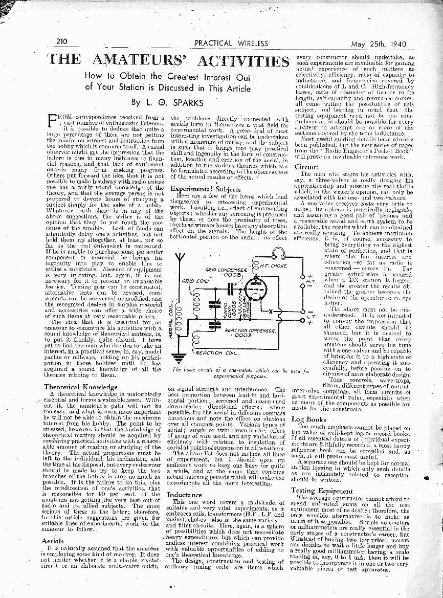
Experimental SubjectsHere are a few of the items which lend
themselves to interesting experimentalwork. Location, i.e., effect of surroundingobjects ; whether any screening is producedby these, or does the proximity of trees,overhead wires or houses have any absorptioneffect on the signals. The height of thehorizontal portion of the aerial ; its effect
azo CONDENSER.0003)
GRID COIL.
REACTION CONDENSER. 0003
k REACTION COIL,
May 25th, 1940
every constructor should undertake, assuch experiments are invaluable for gaining,actual experience of such matters asselectivity, efficiency, ratio of capacity_ toinductance, and frequencies covered bycombinations of L and C. High -frequencylosses, ratio of diameter of former to itslength, self -capacity and resonance curves,all come within the possibilities of thissubject, and bearing in mind that thetesting equipment need not be too com-prehensive, it should be possible for everyamateur to attempt one or More of thesections covered by the term inductance.
Most useful guiding details have alreadybeen published, but the new series of pagesfrom the " Radio Engineer's Pocket Book "will prove an invaluable reference .work.
CircuitsThe man who starts his activities with,
say, a three=valver is really dodging hisapprenticeship and missing the real thrillswhich, in the writer's opinion, can only beassociated'with the one- and two-valvers.
A one -valve receiver costs very little tomake ; its upkeep is practically negligible,and assuming a good pair of 'phones anda reasonable aerial and earth system to beavailable, the results which can be obtainedare really amazing. To achieve maximumefficiency, 'is, of course, necessary to
bring everything to the higheststate of perfection, and that is -
where the fun. .interest andeducation-so far as radio isconcerned - conies in. Fargreater satisfaction is securedwhen a DX station is logged,and the greater the results ob-tained the greater becomes thedesire of the operator to go onebetter.
The above must not be mis-understood. It is not intendedto convey the impression thatall other circuits should beshunned, biit it is desired tostress the point that everyamateur should serve his timewith a one -valuer and be capableof bringing it- to a high state ofefficiency and operating it suc-cessfully, before passing on tocircuits of more elaborate design.
Tone controls, wave -traps,filters, different types of output,
intervalve couplings, all form 'circuits ofgreat experimental value, especially whenas many of the components as possible aremade by the constructor.
Log BooksToo much emphasis cannot be placed on
the value of well -kept log. or record books.If all essential details of individual experi-ments are faithfully recorded, a most handyreference \ book can be compiled and, assuch, it will prove most useful.
A separate one should be kept for normalstation logging in which only such detailsas are intimately related to receptionshould be written.
Testing EquipmentThe average constructor cannot afford to
spend unlimited sums on all the testequipment most of us desire ; therefore, theonly sensible alternative is to make asmuch of it as,possible. Simple voltmetersor milliammeters are really essential in theearly stages of a constructor's career, butif instead of buying two low-priced metersone decides to wait a little longer and buya really good milliammeter having a scalereading of, say, 0 to I mA. then it will bepossible to incorporate it in one or two veryvaluable pieces of test apparatus.
H , T.
L. T.
MEI
The basic circuit of a one-valver which can be used forexperimental purposes.
on signal strength and interference. Thebest -proportion between lead-in and hori-zontal portion ; screened and unscreeneddown -leads ; directional effects
'where
possible, try the aerial in different compassdirections and note the effect on stationsover all compass points. Various types ofaerial ; single or twin down -leads ; effectof gauge of wire used, and any variation ofefficiency with relation to insulation ofaerial at points of suspension in all weathers.
The above list does not include all linesof experiment, but it should open upsufficient work to keep one busy for quitea while, and at the same time combineactual listening periods which will make theexperiments all the more interesting.
InductanceThis one word covers a multitude of
suitable and very vital experiments, as itembraces coils, transformers (H.F., L.F. andmains), chokes-also in the same variety-and filter circuits. Here, again, is a sphereof possibilities which does not necessitate
, heavy expenditure, but which can provideendless interest combining practical workwith valuable opportunities of adding toone's theoretical knowledge.
The design, construction and testing ofordinary tuning coils are items which

May 25th, 1940 PRACTICAL WIRELESS 211
Alternating Current CircuitsA Brief Explanation of Current and Voltage in A.C. Systems, and of theEffect of Introducing Resistance, Capacity and Inductance into A.C. Circuits
By FRANK PRESTONALMOST every reader is familiar with
Ohm's Law and corresponding for -mule as applied to direct -current
eireuits, but there are no doubt many whodo not know how to apply the formulae toA.C. It may at first appear that there islittle need to trouble about this as far asradio is concerned, but there are manyapplications when more advanced work isundertaken. Those applying for enrolmentas radio mechanics in the Services will alsobe interested to know that questions relatingto A.C. theory are not unusual.
It is not possible to cover the matter
Fig. 1.-A typical sine curve representing analternating voltage.
completely and academically in the spaceof an article, but an extensive knowledgeof the theory is not likely to be requiredby the average reader. It is important,however, to have some knowledge of thenature of an A.C. supply, if only because itis comparable to wireless waves.
The Nature of A.C.The expression sine curve is often used
when referring to A.C., the curve taking theapproximate form of that shown in Fig. 1.This merely indicates that the voltagegradually rises from zero to a maximumpositive, back 'to zero, then to maximumnegative and back again to zero. Thecomplete cycle is said to take place in 360degrees-the number of degrees in a com-plete circle-whilst the intermediate pointsreferred to occur at 90, 180 and 270 degrees.
To see what is Meant by these angles it isnecessary to have an impression of themethod of A.C. generation. In a dynamo orA.C. generator there is a pair (or a numberof pairs) of magnet poles, between which acoil rotates. Fig. 2 shows the arrangementiddiagrimmatic form. It may be seen that asthe coil (shown as a simple loop) rotates onits axis, one side moves upward while theother moves downward. And as manyreaders will remember from their school.days, when a wire is moved between twomagnet poles a current is induced in it dueto the cutting of the magnetic lines of force.
Direction of Current FlowSince one side of the loop is moving
downward and the other upward, the cur-rent induced in one side flows toward thepoint marked A, whilst in the other sideof the loop the induced current flows away
from A. When the plane of the loop isvertical, no current flows, because lines offorce are not being cut. But as the looprotates, current starts to flow and increasesuntil the loop, reaches the horizontalposition (with its plane in line with -themagnet poles). It has then turned, through aright-angle, or 90 degrees. As rotationcontinues current continues to flow in thesame direction, but the current falls to zeroas the loop again approaches the verticalposition. The loop has then turned through180 degrees ; see Fig. 1.
Continued rotation causes that side of theloop which was travelling downward to rise,and that which was rising to fall. Thus, theinduced current flows in the oppositedirection. Apart from the direction ofcurrent flow, the sequence of events isexactly as before. Thus, by the time theloop has made a complete circle, the current(and voltage) has varied from maximum
3601 0°
I
S 27020-( 0 --so° N-41
1W00.
Fig. 2.-Diagrani to illustrate the principles of anA.C. generator. The inset illustrates the angularpositions of the loop corresponding with the points
marked in Fig. I.
positive to maximum negative and haspassed through zero. That should help tomake the so-called sine curve more readilyunderstandable.
Why the Name ?It is called a sine curve because the
voltage induced at any instant is propor-tional to the sine of the angle through whichthe loop has turned. The sine of an angle,as known to mathematicians, is the ratioof the vertical height to the hypotenuse of aright-angled triangle, as shown in Fig. 3.Thus the sine of angle a is the length ofside AC divided by the length of side AB.The sine of an angle of 45 degrees is one
1divided by the square root of 2 ( -- or.7071) ; the sine of an angle of 90 degrees isunity. In the latter case it will be seen thatthe triangle " close4 up " into a straightline.
By using graph paper and plotting theinducted voltage at any instant againstthe angle of rotation we get a curve such asthat shown in Fig. 1, when all the pointsplotted are joined together with a smoothline.
The R.M.S. ValueFor most practical purposes the maximum
current reached in an A.C. circuit is (wf littleuse. Instead, we make use of Mutt isknown as the root mean square (or lt.NI.K.)value. This is less than the maximumcurrent, and corresponds t o t he D.C.current. which would produce t lie sameheating- eUt-f inn win(' if, waspasAql. Front I hi:4 it limy seen that ahot-wire ammeter calibrated en D.('. wouldrecord the R.M.S. value of n alternatingcurrent. The actual R.31.ti. value is
1.1M1 .--.=
2") times the maximum value.
Resistance to A.C.When an alternating voltage is passed
through a non -inductive resistance thecurrent can be found by hpplying Ohm'sLaw ; that is, I=E/R. But this simpleformula does not apply when the circuitcontains capacity or inductance. WithD.C. a series capacity, of course, is theequivalent of a break in the circuit, and nocurrent flows. A condenser does not prevent,the flow of A.C., however, since it is con-stantly being charged and discharged. Thecondenser acts more as a resistance to A.C.,the value of the " resistance " (known asreactance) depending ofthe condenser and the frequency of the A.C.
As often stated in these pages, thereactance of a condenser is 1/2.7rit, where z isthe standard 3.14, f is the frequency incycles per second, and C is the capacity in
Fig. 3.-The size of anangle in a right-angledtriangle is the verticalheight divided by the length
of the hypotenuse.
6-
A
Cfarads. If reactance is substituted forresistance in Ohm's Law it is possible tocalculate the current flowing in an A.C.circuit containing a condenser from theformula : where E is the voltageand X the reactance.
An interesting fact about an A.G.circuit containing capacity is that thecurrent " leads " the voltage by 90 degrees.This means that current attains itsmaximum when the voltage is zero.This is clearly indicated by the curves inFig. 4, the light curve indicating voltage,and the heavy lino indicating current.
The position is similar when an inductance(a choke, for example) is in the A.C.circuit. Current can be found by dividingthe voltage by the reactance of the choke,which is equal to 2nfL, n and f being asbefore, and L being the inductance inhenries. In this case, voltage and currentare again 90 degrees out of phase, but thevoltage " leads " the current.
(Continued on neat page)
212 PRACTICAL WIRELESS May 25th, 1940ALTERNATING CURRENT CIRCUITS
(Continued from previous page)
Series ReactancesWhen resistance and capacity, or capacity
and inductance, or capacity, inductance andresistance are in series, the current can stillbe found by using Ohm's Law, but in thatcase the reactance must be taken as thetotal reactance (and resistance, whenincluded) of all the components in series.Without giving the full mathematics of thecase it can be stated that the reactance of aresistance and capacity in series (thecombined value being known as impedance)is represented by the expression
1 2
/1R2+ ) Therefore in calculating2.7tfe
the current this must be substituted for theR in Ohm's Law.
Current --
Fig. 4.-1n an A.C. circuit containing a seriescapacity, thescurrent leads' the voltage by 90°.
When inductance and,Tesistance are inseries, the overall impedance is equal toA/R2+ (27tfL)2.
In both these cases it will be seen thatresistance and reactance are added together.The position is different when we havecapacitative and inductive reactance inseries, since the former is subtracted fr'omthe latter. The reason for this is that, sincein one case the current " leads " thevoltage and in the other the voltage " leads"the current, the two tend ,to neutraliseeach other. Thus it will be seen that thereactance of a coil and condenser in seriesis 27tfL
27rfCIf we have resistance,
capacity and inductance all in seriesthe impedance of the circuit becomes
(27EfL 2ifC1
)2.
In every case, reactance and impedanceare given in ohms.
A SIMPLE U.S.W. CIRCUITAnd Notes on Tuned Radio -frequency Working
THERE are many readers who areanxious to carry out experimentson the short and ultra -short waves,
but feel that it is uneconomical to builda complete receiver for this purpose.It is argued, quite rightly, that after thedetector stage of any set the same form oflow -frequency coupling, output circuit andloudspeaker can apply to nearly all thereceivers they may desire to use. Forthis reason many favour an adaptor orconverter in order to utilise part of thehome set to complete their experimentalinvestigations. This policy is quite asound one, and although it means thatordinary domestic listening on the mediumand long waves is out of the questionwhen the experimenter is carrying out hispart of the listening, this is only a case ofmutual arrangement with other membersof the household.
It is quite a simple matter to build upapparatus so that the signal output canbe plugged into the pick-up terminalpositron of the domestic set, and thedesigns for this purpose are legion. Tomeet the conditions 'of ultra -short waveworking, that is below ten metres, a regionin which so much interest is manifested,since it provides a good deal of pioneeractivities, one of the most efficient schemesis to employ a tuned radio -frequencyconstruction. Associated with this willbe the dipole, aerial and feeder designedto cover the range of frequencies required,and about which data was furnished in arecent issue for those cases where a non-permanent installation Was desired.
T.R.F. WorkingAs an example of one circuit which can
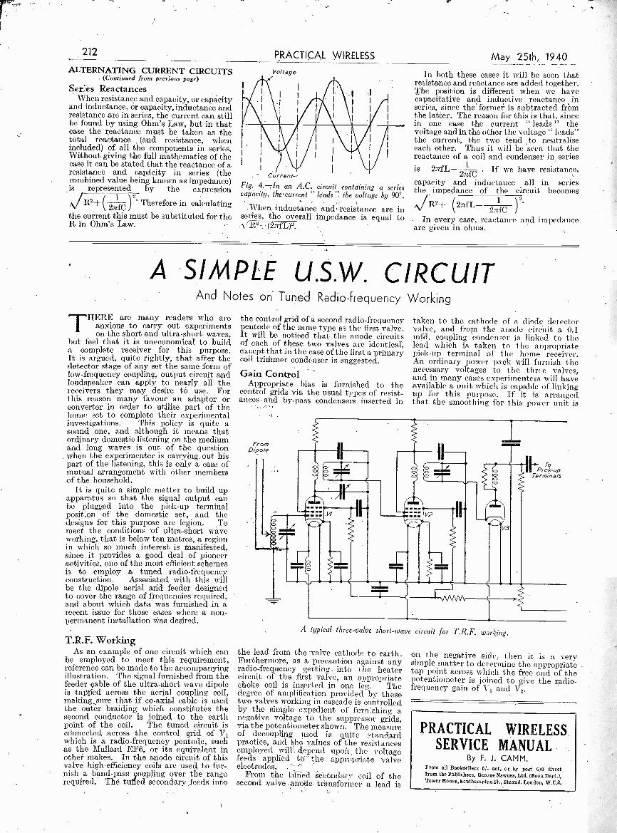
be employed to meet this requirement,reference can be made to the accompanyingillustration. The signal furnished from thefeeder cable of the ultra -short wave dipoleis tapped across the aerial coupling coil,making sure that if co -axial cable is usedthe outer braiding which constitutes thesecond conductor is joined to the earthpoint of the coil. The tuned circuit isconnected across the control grid of V1which is a radio -frequency pentode, suchas the Mullard EF6, or its equivalent inother makes. In the anode circuit of thisvalve high -efficiency coils are used to fur-nish a band-pass coupling over the rangerequired. The tufted secondary feeds into
the control grid of a second radio -frequencypentode of the same type as the first valve.It will be noticed that the anode circuitsof each of these two valves are identical,except that in the case of the first a primarycoil trimmer condenser is suggested.
Gain ControlAppropriate bias is furnished to the
control grids via the usual types of resist-ances and by-pass condensers inserted in
F/0/17DiPole
taken to the cathode of a diode deteCtorvalve, and- from the anode circuit a. 0.1mfd. coupling condenser is linked to thelead which is taken to the appropriatepick-up terminal of the home receiver.An ordinary power pack will furnish thenecessary voltages to the three valves,and in many cases experimenters will haveavailable a unit which is capable of linkingup for this purpose. If it -is arrangedthat the smoothing for this power unit is
II
MS 00
II T Iick-up.F.P
TerminalsO
V3
A typical three -valve short-wave circuit for T.R.F. working.
the lead from the -valve cathode to earth.Furthermore, as a precaution against anyradio -frequency getting into the heatercircuit of the, first valve, an appropriatechoke coil is inserted in one leg. Thedegree of amplification provided by thesetwo valves working in cascade is controlledby the simple expedient of furnishing anegative voltage to the suppressor grids,via the potentiometer shown. The measureof decoupling used is quite standardpractice, and idle values of the resistancesemployed will', depend upoii the voltagefeeds applied to the appropriate valveelectrodes. '"
From the tfined Secondary coil of thesecond. valve anode transformer a lead is
To
on the negative side, then it is a verysimple matter to determine the appropriatetap point across which the free end. of thepotentiometer is joined to give the radio -frequency gain of V1 and V2.
PRACTICAL WIRELESSSERVICE MANUAL
By F. J. CAMM.From all Booksellers 81- net, or by post 6/8 directfrom the Publishers, George Newnes, Ltd. (Book Dept.),Tower House, Southampton St., Strand, London, W.C.2.

FOLLOWING on the recent lettersregarding the intriguing subject offull -wave detection, and as a suitable
seccessor to the article published last week*al the use, of the grid -leak, I am promptedto give some further data relative to thesubject of rectification.
Fig. 1 represents the orthodox theory ofhalf -wave rectification. This not onlyApplies in the accepted view to the recti-fication of low -frequency alternating current,but also to the detection of radio -frequencyoscillations, by which it will be seen thatthe negative half -waves fire,suppresised 1?ythe rectifier.
Fig. 2 represents the orthodox theory offull -wave rectification, by which thenegative half -waves are permitted to flow,but are reversed in direction and becomewholly positive. The process known asrectification 'of low -frequency alternatingcurrent, when applied to radio -frequencyoscillations, is better described as detection.
LI the new theory the accepted view of therectification. of low -frequency alternatingcurrent is assumed to be correct:
NEGATIVE 75 pe, cent of POSITIVE
Fig. 3.-This curve shows the waveform with 75per.cent. negative amplitude.
NEGATIVE 50 per cent of Positive
Fig. 4.-In this diagram the waveform shows thenegative half -cycle 50 per cent. of the positive.
Radio FrequenciesDetection of radio frequencies is a dis-
placement of the base or zero voltage lineso that generally -the positive amplitude isincreased, and the negative amplitudedecreased, so that the positive amplitudeof the output is greater than the negative.This does not take into consideration anyquestion of detector amplification orlosses, which would either increase or de-crease both the positive and negative por-tion of the wave, and would be relatively inproportion. Different methods of detectionand different conditions in the detectorcircuit produce an output which may havea different positive/negative ratio.
In considering the subject of detectionof radio frequencies, it is .necessary firstto consider the detection of an unmodulatedcarrier wave, The question of the modu-lated wave will be dealt with later.
Fig. 3 shows the waveform of the outputfrom a detector, in which the base or zerovoltage line has been displaced so that thenegative amplitude is 75 per cent. of thepositive. This may be the output froma bottom -bend detector working at oneparticular point in its characteristic curve.
May 25th, 1940 PRACtitXL 213
Is Full-wave Detection fin ossibk?An Interesting Analysis on this Important Subject
By D'ARCY FORDFig. 3 also represents the waveform of theunmodulated output of a grid -leek detectorwith a low value of leak (say .025' megohms).
Fig. 4 shows the., waveform of the un-modulated output, of a detector in .whichthe negative amplitude is 50 per cent, ofdthe; poSitive. This represents the oput
HALF -WAVE RECTIFICATION
ZERO-
FULL-WAVE RecripicATi0N
Figs. 1 and 2.-These curves show the, effect ofhalf -wave and full -wave rectification.
. , A
of a grid -leak detector with a leak of say2 megohms. If the wave were modulated,the audio -frequency output from. Fig. 4would be greater than the audio -frequencyoutput from Fig. 3. This is borne out inpractice by the fact that generally the higherthe value of leak in a grid -leak detector, thegreater will be the volume of output, andthe lower the value,of leak the less will bethe volume of output. Of course it requiresa lower value of leak if quality output isrequired from a more powerful input.
Fig. 5 shows a waveform in which thenegative amplitude is, only 20 per cent. ofthe positive. If this were modulated, theaudio -frequency output would be con-siderably increased as compared with Figs. 3and 4. Fig. 5 may -represent the waveformof the unmodulated output of a crystaldetector working under average sensitivity.
Fig. 6 shows the waveform of an outputwhich has a zero negative value, end iswholly positive. This may be difficult toobtain in practice. The writer has not car-ried out sufficient experiments to provewhether the waveform of Fig. 6 is possibleto obtain or not. It shows the detector
NEGATIVE 20 pet cent of Posmve
Fig. 5.-In this waveform the negative amplitudeis only 20 per cent. of the positive.
ZERO
DIFFICULT TO OBTAIN IN PRACTICEZERO NEGATIVE
Fig. 6.-A zero negative potential is indicated bythe waveform in this diagram.
output of an unniodufitcd carrier whichrises. and falls in an increasing and de-creasing positive direct icn with no negativeamplitude. If it is po.,,ilde for this to beobtained in practice. it void enable thefull modulated radio -frequency wave afterdetection to be used as an audio -frequencyoutput.. This is not what is understood asfull -wave rectification. If it is passible inpractice, it could be obtained as the outputof a single crystal (or other suitable recti-fier) in what is regarded as a half -wavedetector circuit I It is therefore not full-wivie detection.
It what appears to be a full -wave detectorcircuit gives a greater volume of outputthan a half -wave deteeter circuit, this wouldbe owing either to inc-eased amplificationin the full -wave circuit, or to a more com-plete detection, so that the negative ampli-tude is further redifeed relative to thepositive.
Modulated WaveWe must now consider the question of a
modulated wave. The new theory is in agree -
ZERO
Fig. 7.-This shows the waveform of a modulatedwave in accordance with accepkd theory.
Fig. 8.-This shows the output from a detectorby a method of detection which displaces the zerovoltage line so that the negative amplitude of theoutput is 50 per cent. of the positive (refer to Fig.4).
ment with the accepted view of the questionof modulation, although it is not in agree-ment on the question of sidebands. Theoutput from the detector does not consistof audio frequencies as audio frequencies,and although orthodox theory admits thepresence of stray radio frequencies in theoutput, it is claimed that the whole of theoutput from the detector consists of a com-posite radio -frequency wave which hasgenerally a greater positive than negativevalue, and which varies in accordance withthe audio -frequency modulations. Theeaudio -frequency variations of the radio -frequency wave make it audible. Mete isno space here to give a definition of thecomponent frequencies of a wave-thatincludes the question of sidebands.
Fig. 7 shows the waveform of a modu-lated wave in accordance with the acceptedtheory, which rises and falls in accordancewith the audio -frequency modulation. Whathas been stated with reference IA, the wave.
(Continued on page 220).

214 PRACTICAL WIRELESS
Obtaini p x g Maximum Efficiencya Class AB Amplifier
An Interesting Resistance-coupled Push-pull Amplifier. CircuitIN planning radio receivers having a
fairly large power output it is necessaryfrom considerations of economy to
design the output stages for maximum'efficiency. For -this reason Class AB push-pin pentode amplifiers have been de-veloped, and it is interesting to examinea typical R.C.A. amplifier and its methodof operation.
The circuit of the amplifier is shown inFig. 1, and it will be seen to consist of twopentode valves (type 6F6) in the outputstage - driven by a double -triode (type6N7) phase inverter. The amplifier is
resistance -coupled, which precludes thedriving of the output valves into gridcurrent. The anode resistors for the phase -inverter may be 100,000 ohms withcoupling capacitors of 0.01 mfd. and gridresistors of 270,000 ohms. The bias for thepush-pull output stage is obtained from thetwo resistors in series in the H.T. negativelead.
Load ImpedanceFor maximum efficiency it is necessary to
select the correct load impedance for theoutput stage as shown in Fig. 2, in whichcurves 60-64 are plotted for various gridvoltages on the two output valves betweenanode or plate voltage Ep and the corre-sponding anode or plate current I.
The load on the anode circuit of the valvesis adjusted to pass the load line 65 of thevalves through the points Ep=-EpO,and Eg= 0 at the knee 66 of the Eg=0curve 60.
The load line for a -single valve is indicatedat 67, and the operating point 68 thereon isso chosen that the valves are biasedinitially, in the absence of signals, close toanode current cut-off, i.e., considerably
below that value of anode current lyingmidway between that corresponding tozero grid voltage, and grid voltage corre-sponding to anode current cut-off. Thisis indicated at 68 in Fig. 2. The pperatingcondition established is such that one valvewill be cut off before the other valvereaches- zero grid voltage, and the ampli-fier may thus operate Class AB. Theoperation is pre -Vented from extendingbeyond Class AB by the fact that thegrids are resistance -capacity coupled andinclude relatively high resistance elementsin circuit, which ,prevent drawing grid
100
Bo
601p
40
20
Fig. 1-Circuit of amplifieroperating on the Class AB
principle. --
May 25th, 1940
from
current. It is, therefore, a problem to obtainmaximum power output without drawinggrid current, and for this reason the loadline 65 of the push-pull operated valves iscaused to pass through the Es= 0 curve atthe knee 66 of the curve, thereby permittingmaximum power output to be developedwithout grid current. Therefore, resistance -capacity coupling may be used, as shown inFig. 1, between the driver stage and theoutput stage. This is advantageous inproviding phase inversion between the usualdiode detector and the output poweramplifier of a radio receiver.
Lead line intersects Eg-0at the knee of curve Ego=0
6061
Load line- singlegE,Load P.P. Amp//Pier
100 200
EpFig. 2.-Plotting of the load line for different
working voltages
Maximum Power OutputTo summarise these results, it will be
seen that maximum power output may be obtained from a pentode power -outputstage having the valves arranged in push-pull relation to each other with resistance -capacity coupling when the load is- suchthat the load line of the two valves in push-pull relation intersects the knee of thezero bias curve of anode current versusanode voltage so that the maximum valueof the product of the voltage across theload and the current through the load isobtained, this being in the present examplethe voltage at the point 68 less the voltageat the point 66 'and the current at thepoint 66, less the current at the point 68.
Ego= -15..(67
68 Operating Pond
9025=-36
300 400
r................---,...,-....,.............-.- ,-.--,...,........1i A COMPLETE LIBRARY OF STANDARD WORKS I/ By F. J. CAMM. II PRACTICAL WIRELESS ENCYCLOPAEDIA 7/6, by post 8/-. I1 EVERYMAN'S WIRELESS BOOK 5/-, by post 5/6. iI SIXTY TESTED WIRELESS CIRCUITS 3/6, by post 3/10. iI COILS, CHOKES and TRANSFORMERS 3/6, by post 3/10. - 1
PRACTICAL WIRELESS- SERVICE MANUAL 61-, by post 6/6. IWORKSHOP CALCULATIONS, TABLES & FORMULAE I
3/6, by post, 3/10. INEWNES' SHORT-WAVE MANUAL 5/-, by post 5/4..
iTHE HOME MECHANIC ENCYCLOPAEDIA 3/6, by post 4/- - 1WIRELESS TRANSMISSION FOR AMATEURS 3/6, by post 3/10. IDICTIONARY OF METALS AND THEIR ALLOYS 5/-, I
by post 5/4.! PRACTICAL MECHANICS HANDBOOK 6/-, by post ' 6/6.
All obtainable from or through Newsagents or from Ceo. Newnes, Ltd., Tower House, Southampton St.. Strand. W C.2It 10 041 0 1101'0100 IO 0.11.11.0.1.1141041.1Z

May 25th, 1940 PRACTICAL WIRELESS
The Length of Receiving AerialsIWONDER how many readers have
observed that the length of aerial nowpermitted by the Postmaster - Generalis 150ft. Formerly, the maximum lengthpermitted, including that of lead-in, was100ft. The 100ft. limit was of value in theearly days in limiting interference causedby oscillating receivers of the detector andL.F. type. With the virtual supersession, ofsuch receivers by superheterodyne receiversand sets incorporating a screen -grid R.F.amplifier, interference caused by oscillationwas greatly diminished, and it was .decidedto increase the permitted length of aerialto 150ft., which agrees with the lengthpermitted in experimental transmittinglicences. The increase was agreed to inMay -June, 1936, and came into force as theforms were reprinted and issued, commenc,ing in early 1937. It should perhaps be
emphasised that the wording on the licencerefers to " the length of the effective portionof the aerial and the down -lead." A screeneddown -lead or a special down -lead in whicha screened single -core or twin -core flexiblecable is connected between the aerial andthe receiver by means of impedance match-ing transformers is not regarded as aneffective portion of the aerial and down -lead. I am obliged to the Engineer -in -Chief of the Radio Branch of the G.P.O.for enlightening me on this matter.
The Woman AnnouncerJOHN SNAGGE is on the look out for
a woman announcer. I hope we do notrevert to women announcers. I resent theintrusion of women into an essentiallymale job. Women announcers have beentried before, and they have failed. I seethat one of the radio experts attached toa daily paper claims to have discoveredthat the bulk of listeners would welcomethe reintroduction of women announcers.How has he discovered this ? Has heconducted a census or is he merely express-ing a personal opinion ? And if hehasconducted a census, bearing in mind thatthere are more women listeners than men,is it not obvious that the majority oflisteners will be in favour of womenannouncers in just the same way that themajority of voters are in favour of votesfor women ? If a census of men listenersGould be taken, it would be found, I am sure,that women would not be wanted for sucha job. In any case, we do not want theB.B.C. to tell us what we want. It is ourjob to tell them. And why is the B.B.C.so interested in reintroducing womenannouncers ? Is it because that previouslySir John Reith was anxious that the B.B.C.should be run by young men, and that nowthat the Army has recruited most of themthey are short of a supply of young men ?If so, John Snagge should say so, not wrapit up with statements about the majority oflisteners wanting them. In any case, I thinkthat listeners should be left to decide..I suggest that Snagge lines up a dozen of theselected applicants after he has finalisedthem and invites listeners to answer twoquestions : Do you want women announcers,and if so, which of this dozen ? It would makean interesting programme item, anyway.
By Thermion
Price Control of RadioMAJOR LLOYD GEORGE, Parlia-
mentary Secretary to the Boardof Trade, has announced that the Prices ofGoods Act will be applied to a widerrange of manufactured goods than thosescheduled last December. The profits onradio sets are now limited and controlledby the Act.
Ganged InductancesI AM informed by the Ekco Company
that in their three new bandspread-tuning superhets shortly to be announced,the ganged condensers will be replaced byganged inductances. The tuning unit is ofnew design and construction, and has beendeveloped by the Ekco Company. Theyclaim that it will provide bandsPreadtuning on all wavebands, thus makingpossible short-wave station names through-out the 31 -metre band, and a 300 degreemovement of the scanning pointer ; as wellas single tuning sub -assembly, carrying coils,ganged inductances, wavechange switch,trimmers and padders, which may be de-tached as a utlit for service or replacement.This is another development of permea-bility tuning which, introduced a few yearsago, did not prove so popular as was atfirst supposed. The release of these modelsis dated for early June.
Happy Landing
ONEof the most extraordinary incidents
of the war so far, was the case of" the air gunner who did not jump."It happened following a reconnaissanceflight.
The aircraft became iced up and un-manageable. The order went back to" bail out," but the rear gunner did nothear the order because his telephone was'iced up also. His companions obeyed theorder, ignorant of the fact that the othermember of the crew had not heard the com-mand. They believed he, .too, had startedto float down.
Still at his post, however, the gunnerin the tail felt glad that they were makinga good course and nearing home. By thequeerest streak of good fortune, the air-craft finally pancaked in safe territory.The gunner, although ;badly shaken,rushed as he thought to the rescue of hisfriends.
Imagine his consternation when hefound that they had disappeared. He had" brought the plane home " alone.
215
B.B.C. Symphony Concerts at BristolIT is interesting to note that a series of1 seven public Orchestral Concerts willbe given by the B.B.C. Symphony Orchestrain the Colston Hall, Bristol, during thefortnight of May 22nd to June 5th.
The scheme comprises three WednesdaySymphony and two Sunday PopularConcerts at 7 p.m. on May 22nd, 26th,29th and June 2nd and 5th, and two LunchHour Concerts to be given at 1.15 p.m. onFridays, May 24th and 31st. Two of theseconcerts will be conducted by Sir AdrianBoult, B.B.0 Director of Music, one byClarence Raybould, Chief Assistant Con-ductor of the B.B.C., and the remainingfour by Sir Hamilton Harty, JulianClifford, Basil earner:it. and Albert Wolff, allof whom, with the exception of Sir HamiltonHarty, will be making their first appearancein Bristol.
Albert Wolff, who is coming speciallyfrom Paris to conduct a concert of Frenchmusic on May 29th, is the conductor ofthe famous Lamoureux Orchestra and ofthe Opera Comique in Paris, and his visitto this country to conduct the B.B.C.Symphony Orchestra will be reciprocated amonth later by Sir Adrian Boult, who hasbeen invited to Paris to conduct the leadingFrench Radio Orchestra on June 28th.
Another feature of these Bristol concertswill be the inclusion of two entire pro-grammes devoted to works by Tchai-kovsky, in commemoration of the firstcentenary of the birth of the great Russiancomposer, who was born on May 7th,1840. The first of these Tschaikovskycentenary programmes will be given at theopening concert on May 22nd, and thesecond, of a more popular character, onSunday, June 2nd. -
The soloists taking part in the series willbe Solomon, Moiseiwitsch and LouisKentner (piano), Lulls, Finneberg (soprano)and Ida Haendel (violin).
The Home Front in FranceMANY feature programmes have had
as their subject the Home Front inBritain. The corresponding effort beingmade by the man -in -the -street in Franceshould prove of equal interest to manylisteners. The term " man -in -the -street 'is now, perhaps, a misnomer, as RobertKemp discovered during a recent tour ofFrance in search of material for threefeature programmes to be produced underthe general title of " The Home Frontin France." Paris, in common with therest of the country, is practically denudedof men under the age of fifty, as themajority of the younger men, are servingwith the French Forces and their work isbeing carried on by their womenfolk. Thetitle of the first programme, which is tobe heard on May 29th, is " Paris Goes toWar," and among subjects to be dealtwith will be rationing, A.R.P. servicesand the black -out. The second feature willfocus attention on the war -time work ofthe women of France, particularly in thebig agricultuxal centres, and the thirdprogramme will tackle the problem ofevacuation.

216 PRACTICAL WIRELESS
Comment, Chat and CriticismMay 25th 1940
Musical History-1A Sketch of the Evolution and Progress o/ Music fromthe Earliest Times, by Our Music Critic, Maurice Reeve
IT can be assumed, without fear ofcontradiction, that music existed asfar back in past ages as speech, and
side by side with it, Unfortunately forthe historian, it was not codified and drawnup with laws and rules governing its usagefor centuries after speech and other artswere. Consequently, whilst we have amaz-ing examples of painting and sculpture, andof primitive articles of domestic use andweapons of war, etc., from the earliest daysof the cave dwellers, still in a state ofperfect preservation, and of literature fromthe earliest Egyptian dynasties and Hebrewchronicles recorded for posterity, as wellas many other ancient arts and crafts, thereis no recorded music for centuries, All weknow for certain is that it has been used
A
a41
worthy of mention are Pythagoras (5410 tee.),Aristoxenus (340 tee.) and Euclid (277 s.c.).
Early Musical InstrumentsTheir favourite instruments were the
flute, syrinx, born, trumpet, lyre, either,psalter, lute and harp. All of these,however, have subsequently been modified,some almost beyond recognition, so thatwhen we talk of, say, the harp of thosedays we mustn't think of the harp ofmodern times. The progress of musicduring all this period was necessarily veryslow, which fact can probably be attributedto the failure to found any satisfactorysystem for recording it, unlike the spokenlanguage, and the consequent absence ofany concrete foundation from which its
J. Ias a means of self-expression for as king asthe spoken word itself. The most ancientwriters testify to its use as part of thepagan celebrations in the dawn of history,and the frescoes on the caves and tombs ofthe ancient world show men playing weirdand long-ext i net instruments in accompani-ment to the rites of religion, the chase, theGlance, etc. But, as already mentioned,ages were to pass before it could be reducedto a system which would enable it to be
composed " and recorded on paper. Itmust have consisted of the most elementarysounds, expressive of such emotion asworship and adoration, fear, and pleasure,and as an accompaniment, with the tom-toms and other forms of " tympani," tothe dance.
First System of NotationIt was widely practised by the ancient
Egyptians, Greeks, Romans and Chinese,the Greeks using it in conjunction with thepresentations of their wonderful Drama.Terpander (670 s.c.), a flautist and theo-retical musician, is credited with devisingthe first system of notation for recordingmusic, instead of having to have recourseto memorising it, as before. The Greekscale was founded on a system of tetra -chords, a series of four notes with a compassof a per -feet fourth, each containing twotetrachords. The four modes were Dorian,Phrygian, Lydian and the 3lrxi iydian.They were later increased to seven. Onecan play these modes by starting on anykey and following the white notes on thepiano upwards : the Dorian, Jim example,starts on D. These modes have exercisedan appeal on composers of all ages, and thereader will recall that Beethoven wrote oneof the movements of his great quartet,Op. 132, in the Lydian mode, as a thank -offering for his recovery from a severeillness. Other musicians of this period
j
Examples of how "GodSave the King " wouldsound if u ritten in(A) the Doti an Mode;(B) in the Phrygian ;and (C) in the Lydian
style.
study and development could proceed,What we would call its " notation " con-sisted of a series of dots, dashes and signsundecipherable to all but the pedagogue.Two other points must be noted. Ancientmusic was chiefly vocal, the instrumentsbeing used mainly to " double " a line, toemphasise a rhythmic beat, and even tocover up a mistake by one of the singers.Also its extreme ugliness. judged by anystandard that we know to -day. Teoexamples, taken from " Burge 's History,"will amply prave this.
It must not he forgotten, however, thatmusic- possessed no laws or granonar, andthat it was almost exclusively used for
t'T a as later substituted by DO, 'e hich isnoire suitable for singing. and the finalsyllable Si was not introduced mud Interstill. Spas e prevents us from quoting themusic which Guido used in teaching hischoirs singing.
Hebrew music, probably derived from theEgypt roe was largely Eastern in chat aeter.The OH Testament is full of proof t hat theJews %%ere, musically, far in advance of theGreeks, or any previous civiliation. SirW. H. Hadow says : " It is not toomuch to say that the Old Testamitit issaturated with a love of music. Its mostprimitive history contains the figure ofJuba!: the passage of the Red Sea iscelebrated by Miriam, and the defeat ofJubins army by Deborah ; Saul's melan-choly is soothed by David's harp; Elijah,called nikai to prophesy, asks for a minstrelto inspire hiiu. The Temple sorytees to, reInagnincent Outbursts of tuusio-- the his-terical and prophetic books made inallusion to wedding songs and funeral sows,to Songs of the reapers and vintagers.
Recorded NotesAlthough notes were by now roe aded,
including the use of distinguishing colours,no laws as yet existed for either the varia-tion of the sounds produced in unis,ar or ofmeasuring the length for which tley weresustained. Music was still without harmonyor time, Frame) of Cologne, who lived at,the end of the twelfth century, was tine first,to devise a system for the rei..ordiru4 of andironing of various tiim, lengths with theirequivalents in rests, and his system, withadditions and enlargements, remains in useto this day.
Bar lines were not used, but lines weredrawn across the stave Lo mark the end ofa phrase. There were fwo styles of time,lieri.el't and imperfect. The pertect pro -
0 --a-ct o-PA - rod- SEA/ - Po - - Aius - ES - Ft - -e- C's
0 I 0---0-
0 n 0
- Two examples of earlymusical notation takenf rom Burney's History.
REF- CO( - t/ - 00- Mt -- roE - 44.44 - tS - uv - - SO -tit-11r
chanting and facilitating the reciting of theservices.
The Tonic Sol-faAlthough it is incorrect to attribute the
invention of the tonic sol-la system toGuido of Arezzo (9115-1050) he wasresponsible for its spread and subsequentlyuniversal use. In reality, however, it isnothing but some of the syllables from aLatin hymn to St. John the Baptist :
UT queant laxis REsonare fibris,flea gestorurn, FAmuli tuorumSOLve p9lluti LAbii reatuni
Sartete Joannes.
(seeded by multiples of three, and wasdeemed perfect by comparison with tkeHoly Trinity. The sign used was the
ei rele O. The" imperfect " progressedin tisk/S. and was shown by a broken circle,or C, which sign is still in use.
Mention should be made of the earliestexamples extant of part singing as we knowthe terra to -day ; a piece of music con-taining the elements of harmony, melody,time and rhythm s now universally,practised. It is the celebrated " Reading,," Rota," or " Round " " Summer is ieureenin, Ihude sing cuccu," written for four tenorvoices with a " ground " for two basses.

May 25th, 1940 PRACTICAL WIRELESS
Practical HintsAn Automatic Emergency Light
WHILE working in my radio den I amriconstantly blowing the fuses and
leaving myself in darkness. This caused
A novel switching arrangement for emergencylighting.
me to devise the following dodge. A piece ofclock spring was mounted on an eboniteblock, as in the- sketch, and a piece of fusewire was fixed to the end of the springand to a terminal on the base. The springwas adjusted so that when the wiremelted, the spring moved upwards, closinga circuit consisting of a battery and bulbmounted near by. Thus, when the deviceis fixed to the mains -as in circuit diagram,and the fuse wire is blown, a lamp lights up,thus enabling me to find a torch to replacethe fuse.-W. T. GLASSPOOL (Hounslow).
Counting Coil WindingsI RECENTLY wanted to count the number
of turns on a finely wound medium -wave coil, and devised the simple, butaccurate, device shown in the accompanyingillustration.
In my junk -box I found an old butsensitive moving -iron speaker. Afterremoving the cone I filed the reed to asfine a point as possible, and fastened the
WelltflelletraNgergIN
Vl %!!,Actuating rod filed
to a point Coil
Terminals forphones
An improvised counter for fine coil windings.
reIMP11.171:1,1411r,111111.0411104,411041411,0411111.11411111.
1 THAT DODGE OF YOURS il. ; Every Reader of " PRACTICAL WIRE-I LESS, must have origniated some I i ttle dodge
iwhich would interest other readers. Whyhot pass it on to us? We pay C1-10-0 for the ibest hint Submitted, and for every other itempublished on this page we will pay half -a- iguinea. Tiled that idea of yours to account by
I sending it in to us addressed to the Editor," PRACTICALWIRELESS," George Newnes,Ltd., Tower House, Southampton Street,Strand, W.C.2. Put yoite name and addresson every item. Please note that every notionsent in must be original. Mark envelopes" Practical Hints." DO NOT encloseQueries with your hints.
41H 11.01.11111111.1.M11.11
10.1111.411M-0.111.1.110.1N100411.1.10.1.11113.0.110.04101101141.11.141.1 HMV
SPECIAL NOTICE !
iAllhints must be accompanied by the
= coupon cut from page 228.LIIIM.11.10.1111.0.001,411100.11141M.04011.MINI.111110411/111.1
unit (as shown in diagram) to a pieceof wood to act as baseboard. I thenconnected a pair of 'phones to thespeaker unit. To count the number ofturns of a coil, draw it sloWly over thepointed reed, and note the number ofclicks in the 'phones.-J. S. 'WALKER(Kirton).
A Flux Gun and Switch Cleaner ,
AFLUX gun, handy to use, com-bined with neatness, is described
below. The barrel is made from a dis-carded electrolytic condenser. Fig. 1is a sectional diagram of the gun, anti_the parts required are a spout takenfrom an oil can, a rubber washer D,two metal washers, a length of screwed'.rod C,- and knob E. - The spout issoldered to the fixing nut of theelectrolytic. The rubber washer is
111111111111111.11OIRWIN1111111=1101,
Nuts Plug
Body of wet electrolytic- condenser,
Nut
taflPlug
217
the barrel can be adjusted by the two nuts.A fairly tight fit is desirable. The nuts aresoldered firmly to the screwed rod andmetal washers to prevent working loose inaction.
A nut is soldered to a metal plug made tofit tightly in the end of the barrel or,_alternatively, the metal plug itself couldbe tapped. The rest of construction isclear from the diagram.
The switch cleaning device is similar inconstruction, but in this case a wet electro-lytic condenser is best. The condenser willusually be found to be sealed with a rubbervalve. This is cut away and the contentsemptied. A spout i t fitted as in the fluxgun. The positive; contact screw is eitherpulled out or pushed inside the can, but thefoil contents can rein ain. A pipe cleaner ispushed through the spout, the can is filledwith carbon tetrachloride, and a smallwooden plug seals the small filling hole.
REACTION COILCircuit diagram showing how a reaction difficulty wa'
overcome.
Pipe cleanerThis handy flux gun and switch cleaner were
contrived from old condenser cases.
sandwiched between two metal washers,and two nuts on the screwed rod. Thetightness of the fit of the rubber washer in
The PRACTICAL WIRELESS
ENCYCLOPEDIABy F. J. CAMM(Editor of "Practical
Wireless")Wireless Construction, Terms,and Definitions explained and il-lustrated in concise, clear language -From all Booksellers or by post 8/- from GeorgeNewnes Ltd., Tower House, Southampton Street,
Strand, London, W.C.2.
6th Edition
716 Net
This device will be found invaluable ingetting into awkward corners, as the pipecleaner can be bent into any shape.-E.NEWBAULD (Middlesbrough).
Smoother Reaction -
j RECENTLY made up a simple detectorshort-wave receiver with home-made
coil: Whilst results were very good therewas one serious drawback and that wasthat reaction was not smooth enough toenable me to pull in some of the veryweak stations. I made several trials withdifferent condensers and reaction windings(and also the disposition of the windings),but none of the modifications had anyimprovement. Finally, I adopted thearrangement shown in the accompanyingtheoretical diagram. I used a differentialcondenser in place of the standard reactioncomponent, and added a half -watt 100 ohmresistance. This was at first put on theanode side of the reaction winding inaccordance with standard practice, but itseffect in my case was more marked when itwas put on ,the other side, with the reactioncondenser connected as shown. Althoughthe moving vanes were not earthed. thehand -capacity effects were removed byscreening the reaction lead as indicated.This also proved more efficacious than withthe orthodox connection having the movingvanes earthed.-D. WALDE (Plymouth).

218 PRACTICAL WIRELESS
HORT-WAVESECTION
USING ASHORT-WAVE CONVERTER
How to Ensure Maximum Results from a Converter -receiverCombination.-By W. J. DELANEY.
THE majority of listeners, know that abroadcast receiver may be adaptedfor short-wave use by using an adap-
ter or a converter. The first is merelya substitute for the tuning section of thedetector stages, whilst the second is anadd-on unit which converts the broadcastreceiver and unit combination into a super-het. When properly used this combinationis ideal for all normal uses, but there are a fewpitfalls which appear to crop up from timeto time and prevent listeners from obtain-ing the desired results. The converter is,as already stated, an add-on unit, and it isusually provided with an output terminal orlead, as well as an aerial and earth socketstrip or terminals. In addition there may beprovisions for the necessary battery sup-plies. In all normal cases the aerial andearth are removed from the receiver, andare connected instead to the terminals On theconverter, the -output terminal or lead onthe converter then being taken to the aerialterminal on the receiver. 'There are twopoints here which should be attended to ifyou are unable to obtain satisfactoryresults after making the usual adjustments.Firstly, it may be necessary to join theearth terminal on the receiver to- the earthterminal on the unit, so that .both areearthed. On the other hand, the necessaryearth connection may be obtained throughthe battery supplies.
Battery ConnectionsIf the necessary supplieS are obtained by
means of a plug-in adapter, which isintended for insertion between one of thereceiver valves and its holder, it may beworth while to try alternative positions forit. Inclusion of the adapter, on the L.F.side of the receiver may result in some formof L.P. instability, although it may beadvised that the L.F. section be used, as itwill generally have available higher H.T.voltages. The ideal arrangement is un-doubtedly the use of separate battery leads,especially in the case of the pentagrid orsimilar valves, as then the appropriatevoltages for screen and H.T. are readilyfound and the valve will give its maximumperformance.
A large number of broadcast receivers areprovided with a series -aerial condenser,and this is generally wired direct inside thereceiver. Consequently, when the outputfrom the converter is fed to the receiver itwill have to pass through the condenser.As there is already a condenser in the outputlead this means that you will be using twocondensers in series, and the value of thereceiver aerial condenser may affect results.It should therefore be short-circuited inorder to see if results are improved thereby.Similarly, certain commercial receivers,especially those of the superhet type, havewhistle interference eliminators or similardevices included in the aerial circuit and
these may prevent an S.W. converter fromgiving its best or even prevent it fromworking entirely. If, therefore, you areusing a commercial receiver with anS.W. converter and results are disappoint-ing (or are- thinking of getting a converterfor such a receiver, and are uncertain as to
Vmin4 .0001 MFD
3 TURNS
HL C003 MFD
.0003MFD
5 TURNS
May 25th, 1940
adjusted to some pre -arranged position andthere left. All subsequent tuning is thencarried out on the converter. If the tuningcontrols of the receiver are moved, then thesettings of the converter will also be upset,and thus for accurate logging it is essentialalways to see that the receiver controls areset to the same position. A point whichoften confuses the beginner is that allstations with the standard type of converterwill be found to tune in at two points on theconverter dial. However, if one or twostations on a giveh band are locatedit will not be found difficult to markoff the scale according to the band offrequencies covered by the coil, and thusany doubt as to the correct setting will beovercome.
Tuning RangeIn the ordinary way the converter is
designed for use with plug-in coils, and thusthe range is restricted according to the coilsin use. The receiver may, however, begiven greater scope if one of the ulti-range coils which are now available is
e s.w.Hc>
00 2 MFD
2mca
I MFD
its suitability), the makers of the receivershould be approached for their recommen-dations on the matter.Double Tuning
With a converter the receiver is generallytuned to the long -wave band and the dials
A New Handbook
THE FLYINGREFERENCE BOOK
by F. J. CAMM-Is a Complete Guide to All Types of
I Aircraft, and especially Valuable at the IPresent Time. a
It is packed with Facts and FiguresRelating to All Branches of Flying.
Just Off the Press, it is Right up to date. iPrice Ss. from all booksellers, or 5s. 6d.
by post from The Publishers, C,Arthur Pearson, 'Ltd., Tower House,Southampton Street, Strand, London,
W.C.2.1.1111Mq e. MINN 111Mol f 1.( e 140
H F.0
HT.+1
HT -f2
OU 1"131..11f
001MFD
LT-
Circuit of a typical2 -stage S.W.
superhet eonverter.
fitted. These coils, such as the Bulginfive -range or similar components, may bemounted in the converter, and if themedium -wave and long -wave sections arealso included, then the set may be convertedinto a superhet, although the results maynot be so good as those obtained with asuperhet which has been properly designed.If, however, the tuning circuits in thereceiver are properly screened and theset is quite stable, then there is no reasonwhy it should not perform exactly in thesame manner as a standard superhet, andif care is used it may even have advantagesin that the intermediate -frequency, that is,the frequencies to which the receiversection is tuned, may be correctly adjusted,and any drift due to stray capacities, etc.,may be overcome. It should be remembered.however, that if a converter unit is made upon the lines of a modern superhet fre-quency -changing stage, and one of thestandard oscillator coils is used, then it maybe necessary to modify the coils in thebroadcast receiver in order *to tune to theintermediate frequency for which the oscil-lator coil is designed. There is a possibilitythat this frequency may not be covered bythe coils in the receiver, and therefore thecombination will either fail to work or, atleast, will work very inefficiently.

May 25th, 1940 PRACTICAL WIRfLESS
HOW MUCHHIGH TENSIONThe Importance of the H.T. in Regard to ObtainingMaximum Performance and Effecting Economies
IN spite of all that has been written by the slope of the curve, is considerablyconcerning the desirability of providing greater at high anode voltage than at low.a receiver with an ample supply of In the case of the detector stage, the value
high-tension energy, cases are constantly of liberality in the matter of high-tensionarising in which poor reproduction results voltage is equally marked. In the old days,from either misdirected high-tension .econ- when the leaky -grid triode detector valve-
+. omy or from sheer lack of knowledge on this with magnetic or capacity reaction was usedimportant subject. almost universally, the guiding precept in
The value of a liberal ' allowance of designing the detector stage was to use thehigh-tension voltage can be grasped very minimum high-tension voltage which gaveeasily by a study of the various stages in a__ adequate output combined with effectivemulti -valve -operated receiver. Consider and smooth reaction. Those were the daysfirst of all the high -frequency amplifying when two or more stages of low -frequencystages. Like all amplifying valves, radio- amplification followed the detector, andfrequency types, whether of the screen:grid when, moreover, the efficiency of high-or the high -frequency pentode variety, frequency amplification was far below whatdepend for distor- 3.0 it is to -day, with the result that onlytionless reproduction comparatively small grid inputs were appliedon being worked over to the detector valve.the straight portion To -day, however, 'thanks to the screen -o f their grid -volt grid valve, and to the high -frequencyanode -current char- 2.5 pentodes, large stage gains are possibleacteristic. If, in an on the high -frequency side, and very seldomendeavour to econo- is it necessary to interpose a low -frequencymise in high-tension amplifying stage between the detector andcurrent, 2.0`Q. the output valve. This means that thethe anode detectoi must be able to handle compara-voltage is .b tively large input signals and must, in
-.v
'N. addition, add,its full quota of amplificationsiderably,
,..,..in order to load the output valve.
the effective 1:5grid bias iscorre s p ond-ingly short-ened, andthe valve
30 2-5 20 /5 /0 056/rid Voltage
Best Detector ConditionsWith a triode -detector valve this can be
achieved only by operating the valve underiO what is known as " power- grid " condi-
tions. In this _arrangement, the anodevoltage is increased, if possible, to the
A, maximum value, for which the detectorb valve is rated, and as a result the anode
.5 current is correspondingly increased.Operated. under these conditions the valve
will rectify quite powerful signals withoutdistortion, and its amplifying powers are
Fig. L-A family of static characteristic curvesfor a screen -grid valve.
will therefore fail to handle Arong sigUalswithout distortion.
Affecting Over-all PerformanceThis point is illustrated in the diagram
reproduced in Fig. 1. Here is shown a" family " of static characteristic curves fora typical screen -grid valve of the fixed -mutype, and the way in which the maximumpermissible "eignal is limited by the valueof the anode voltage can be readily appre-ciated. First of all, over-all performanceis affected in several ways. For example,it is clear that at a reduced anode voltagethere is a considerable risk of overloadingthe valve on strong signals, mad the onlyalternative is to reduce the input, which inits turn will reduce the amount of poweravailable at the output stage to operate theloudspeaker. In thistonnection, it must notbe foilgotten that many modern speakerslack considerably in quality when operatedat low power. Then the characteristic -curves themselves show that the mutualconductance of the valve, as represented
Fig. 2.-Illustratingthe different signal=handling capabilitiesof leaky -grid andpower -grid detection.
/2 /0 8Grid kolter9e
6
4
a 4Leaky0 Grid.
Maier Grid.
219
Actual Anode Curreat.A7
Mean'nodeCurrent ":8e-
:7:": _
4 .7i/I72.
AC Component. C.
Fig. 3.-The steady or mean output current withthe alternating component superimposed.
also exploited to the full. But since power -grid detection necessitates a somewhatheavier anode current, i.;(3 benefit cannot beenjoyed unless the listener is preparedto accept this additional drain upon hishigh-tension supply.
Fig. 2 illustrates the effect of power -grid.detection when compared with the ordinaryleaky -grid system, the difference in signal -handling capabilities and -in anode -currentconsumption being illustrated very clearly.
It is, however, in connection with the out-put stage that the ill effects of parsimonyin high-tension supply are perhaps mostnoticeable. It should be borne in mind thatin the output stage is generated the actualpower required for driving, the loudspeaker.
In all other stages the only effect requiredis to produce in the anode circuit of thevalve as large an alternating current aspossible ; the power question does notenter into the matter, and the consumptionof anode current is merely incidental andperhaps unfortunate. But the output valvemust provide a considerable amount ofalternating power, as represented by theproduct of alternating voltage developedacross the " load " in the anode circuit(speaker or output transformer) .and thealternating portion of the anode current.
Insensitive Large SpeakersMany speakeri which are noted for the
fidelity of their reproduction area coin-; paratively insensitive, that is to say,
they require a larger power input toproduce a certain volume of sound thansome of the more sensitive but somewhatless faithful reproducers.
Most listeners know that with thenormal or Class " A " output valve theA.C. component of the anode currentconsists of variations of current strengthabove or below a steady or " mean " value,which latter represents the normal anodecurrent as measured by an ordinarymilliammeter. This is shown in the familiardiagram reproduced in Fig. 3, where thetop horizontal line represents the " rest "value of the anode current, while the curvedline represents the actual anode currentwhen signals are being received, and thedotted curved line shows the equivalentA.C. component. It is not difficult tounderstand that the actual anode currentmarked " A " is equivalent to a combina-tion of the steady value " B " and theA.C. component C." It is also clearthat the amplitude of the alternatingcomponent will be limited by the valueof the steady current, since the full " module.-ation " value is given by this mean current.
If, therefore, a really large output is
220
HOW MUCH HIGH TENSION ?(Continued from previous page)
required from a Class " A " valve it mustbe of a type having a fairly large anodecurrent in order to accommodate largevariations. It is for this reason that thegeneral quality of reproduction in mainsreceivers is usually so very much betterthan in battery sets. With mains powerat a few pence pet unit only, the listenercan afford to be generous with high tension.With battery operation, however, the totalH.T. consumption must be, limited at leastto the economic maximum discharge ratioof the high-tension battery employed.Question of Cost
This brings to the front another aspect of the question of providing generous high-tension supply. The difference in costbetween expending 20 milliamps, and, say,50 milliamps, in the high-tension circuitsof a mains receiver is a mere detail2-amatter of a few pence per week only.
In considering the case of the listenerwho has no alternative but the dry H.T.battery, it can at once be said that he willbe wise to allow as heavy a consumptionas he feels to be justifiable, bearing inmind the two facts that liberal H.T. makespossible improved performance all round,but at the same time adds to the cost oflistening.
Most high-tension batteries, even the" standard ' types of quite low capacity,will give quite a big current for a limitedtime, but only the battery designed for heavydischarge currents will stand up to suchservice for a reasonable time.Battery Types
The " standard " type of battery shouldnot be called upon to give more than 6 or8 milliamps, and under this duty theirlife is quite satisfactory. " Power"typeSor so-called double -capacity batteries areusually rated for drains of the order of12 to 15 milliamps, while the heavy -duty -
triple -capacity type may be used wherecurrents up to some 20 milliamps arerequired. Each type of. battery will givea reasonable life provided its recommended
duty is not exceeded. The costs of thevarious types are in prOportion to theircapacities, but even so it definitely pays touse a battery at least one size larger thanthat indicated by the total anode currentrequired by the set. The reason is thatthe useful life of a battery is not strictlyinversely proportional to the drain, so thatwith a loading of, say, 10 milliamps,double -capacity battery will give more thantwice the life of a single capacity battery.
IS FULL -WAVE DETECTIONIMPOSSIBLE ?
(Continued from page 213).forms of the unmodulated carrier forms thebasis of the detection of the modulatedcarrier.
Fig. 8 shows the output from the detectorby a method of detection which displacesthe base or zero voltage line so that thenegative amplitude of the output is 50 percent. of the positive as is the case of Fig. 4.Other methods of detection will give adifferent positive/negative ratio. Thegreater the excess of positive voltage overthe negative, the greater will be the audio-frequency output.
In the absence of evidence to the contrary,it is clear that half -wave and full -waverectification is impossible. A full -wavedetector circuit can, of course, be used, butthat does not mean that full -wave detectionis obtained. There may, of course, be pointsof detail which may have to be revised, butit is thought that the general principlesremain.
PRACTICAL WIRELESS May 25th, 1940
Dqtritish. Long-DistanceAitnseersCub ezDisappointing News
AS many Members may already know,the existing conditions are likely torestrict their activities concerning
the sending of veri's and reception of QSLcards from countries overseas. Althoughwe are not using official phrases, it shouldbe noted that it is no longer permissible tosend reports of transmissions out of thiscountry or to receive. - QSL cards fromoverseas. It is, therefore, up to all membersof the B.L.D.L.O. to assist the- authoritiesby making careful note of this statement, andto refrain from such practices in the future.
Although this will be very disappointingnews to those who make a big feature ofcollecting QSL cards, it does not in anyway affect oft" restrict the activities of thegenuine amateur.
DX ContestAS this copy goes to press some weeks
in advance, it is too early for us tosay what the actual response is going to beto the proposed DX contest, but' judgingfrom correspondence already received, itwould appear that the majority of themembers are very eager to take part in sucha competition. There are, however, aSmall percentage who have the impressionthat to take part in a long-distance recep-tion contest it is absolutely essential forthem to own an elaborate receiver. Thisidea is absolutely erroneous, and we wouldstrongly advise those who have it toremember our remarks, and that specialprovision would be made so that the stationusing a single-valver would have as muchchance of scoring top marks as the com-munication receiver operator. If you havenot already let us know whether you arewilling to take Part in the contest, pleaselet us have your views as quickly as possible.
An Interesting Point16 EMBER 2603 has raised a very interest-IV! ing point connected with the pro-posed DX &infest, and we would certainlywelcome other members' views, as wequits appreciate that it is a matter whichcan affect all who take part.
The Member says : ' Re DX contest,I think the zone idea is O.K., and wouldgive it all my support. I have one sug-gestion to make, however. It should notbe expected during existing conditions thatmembers should have to sit up half thenight to log DX stations, as most of usare on war work or that which requires usto get all the sleep we can. The period23.00 hours to 06.00 hours should bedefinitely left out. If some members canlisten all night it gives them a definiteadvantage over those whose listening isrestricted to normal hours."
Diversity ReceiversIT is possible that many members wereI not familiar with diversity receiversuntil they read the articles in our issue ofMay 11th, but such circuits are by no meansnew to American amateurs. Now thatmention has been made of them, it is hopedthat we shall hear more about them in thenear future, as they can provide mostinteresting material for experimental work,particularly on the short waves.
The receiver described in the two issuescommencing May 11th -is, of course; designedfor use with a single aerial and, primarily,for the reception of a medium -wave stationwhich is transmitting on two wavelengths.The alternative system, and the one mostsuited for short-wave work, is that whichoperates in conjunction with two separateaerials, and where space permits, it is thisarrangement which we would recommend -to all members who are looking for a freshfield of experimental work. If anyonehas already compiled any practical observa-tions from their own work, then perhapsthey will send them along so that allmembers can share the benefit of theirexperiences.
Station EquipmentTHERE seems to be a great divergence
of opinirin as to what constitutes thecorrect or essential equipment for theaverage amateur station. If many of thephotographs of American amateurs' instal-lations are examined, one cannot help
smallgettingthe opinion that a fortune hasbeen spent on securing rather elaborate testequipment which would seem more suitedfor a professional service man than theaverage constructor. - However, while. it isthe desire of most of us to obtain a finerange of testing instruments, it is possibleto let our enthusiasm over -ride practicalconsiderations, and make or secure appara-tus which is not really essential. There areno hard-and-fast rules as to what constitutesthe equipment of a station, as so muchdepends on the particular work beingundertaken by the owner, but everymember should make every endeavour toconstruct a reliable universal meter, suitablefor measuring a wide range of voltages andcurrents, modulated oscillator for gangingcircuits and checking up the L.F. responseof a receiver or amplifier, aria finally, oneof the simple types of valve voltmeter whichenables measurements of great interest andimportance to be obtained.
With the ServicesWE feel sure that all members will join
us in wishing the beat of luck toMember 6331, who has just notified us thathe is now- a radio -operator in the R.A.F.
Contacts RequiredEST Croydon : Member No. 6,663,
42, Oakfield Road, West Croydon,Surrey.
Folkestone : Member 6,364, Strathmore,121, Surrenden Road, Folkestone, Kent.
Saffron Walden : Member 6,461, 18,Debden Road, Saffron Walden, Essex.
Birmingham : Member 6,676, " Oakfield,"Kendal End Road, Barnt Green, nearBirrningham.
Thames Ditton : Member 6,690, " Ash -bourne," Orchard Avenue, Thames Ditton,Surrey.
Redditch : Member 6565, of 43, BatchleyRoad, Redditch, Words.
-
Brighton : Member 6689, of 48, FreshfieldStreet, Brighton, 7, Susset. 1':
Clayton -le -Moors : Member 6696, of 65,Grange Street, Clayton -le -Moors, nr.Accrington, Lancs.
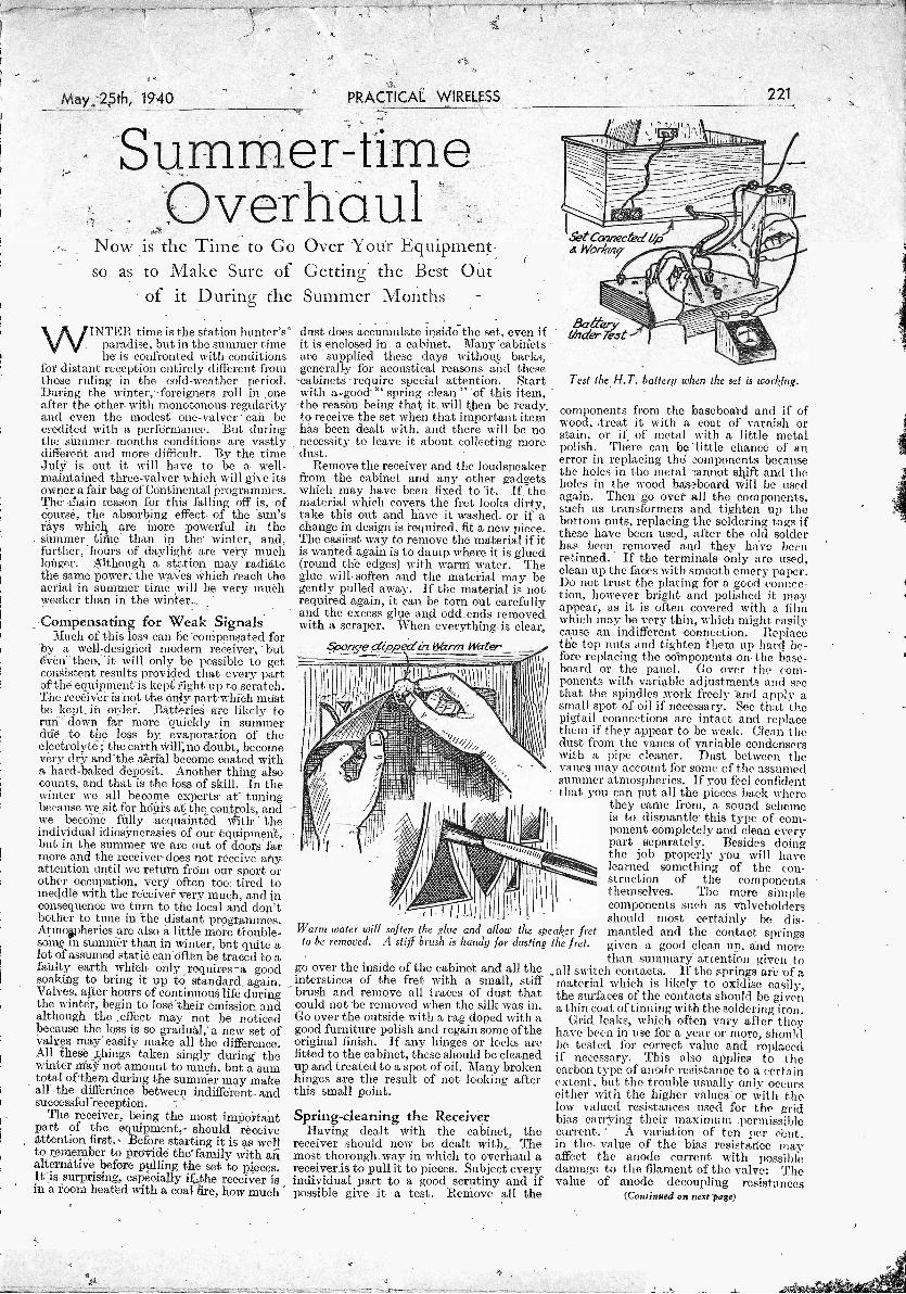
May 25th, 1940 PRACTICAL WIRELESS
Summer -timeOverhaul
Now is the Time to Go Over Your Equipmentso as to Make Sure of Getting the Best Out
of it During the Summer Months
WINTER time is the station hunter'sparadise, but in the summer timehe is confronted with conditions
for distant reception entirely different fromthose ruling in the cold -weather period.During the winter, -.foreigners roll in oneafter the other- with monotonous regularityand even the modest one -valuer can becredited with a performance. But duringthe summer months conditions are vastlydifferent and more difficult. By the timeJul? is out it will have to be a well -maintained three-valver which will give itsowner a fair bag of Continental Programmes.The main reason for this falling off is, ofcourse, the absorbing effect of the sun'srays which are more powerful in thesummer time than in the winter, and,further, hours of daylight are very muchlonger. Although a station may radiatethe same power, the waves which reach theaerial in summer time will be very inueliweaker than in the winter.
Compensating for Weak SignalsMuch of this loss can be compensated for
'by a well -designed modern receiver, -buteven then, it will only be possible to getconsistent results provided that every partof the equipment- is kept right up to scratch.'The receiver is not the only part -which mustbe kept in order. Batteries are likely torun down far more quickly in summerdue .-to the loss by evaporation of theelectrolyte ; the earth will, no doubt, becomevery dry and the aerial become coated witha hard -baked deposit. Another thing alsocounts, and that is the loss of skill. In thewinter we all become experts at tuningbecause we sit for hours at the controls, andwe becoMe fully acquainted with theindividual idiosyncrasies of our equipment,but in the summer we are out of doors farmore and the receiver does not receive anyattention until we return from our sport orother occupation, very often too: tired tomeddle with the receive!' very much, and inconsequence we turn to the local and don'tbother to tune in the distant programmes.Atmopherics are also a little more ttouble-some in summer than in winter, but quite alot of assumed static can often be traced to afaulty earth which only requires - a goodsoaking to bring it up to standard, again.Valves, after hours of continuous life duringthe winter, begin to lose their emission andalthough the effect may not be noticedbecause the loss is so gradual, a new set ofvalves may easily make all the difference.All these things taken singly during thewinter may not amount to much, but a sumtotal of them during the summer may makeall the difference between indifferent- andsuccessful reception.
The receiver, being the most importantpart of the equipment,' should receiveattention first. Before starting it is as wellto remember to provide the family with an`alternative before pulling the sot to pieces.It is surprising, especially if the receiver isin a room heated with a coal fire, how much
dust does accumulate inside the set, even ifit is enclosed in a cabinet. Many cabinetsare supplied these days without backs,generally for acoustical reasons and thesecabinets require special attention. Startwith a,good- "spring clean " of this item,the reason being that it will then be readyto receive the set when that important itemhas been dealt with, and there will be nonecessity .to leave it about collecting moredust.
Remove the receiver and the loudspeakerfrom the cabinet and any other gadgetswhich may have been fixed to 'it. If thematerial which covers the fret looks dirty,take this out and have it washed, or if achange in design is required, fit a new piece.The easiest way to remove the material -if itis wanted again is to damp where it is glued(round the edges) with warm water. Theglue will soften and the material may begently pulled away. If the material is notrequired again, it can be torn out carefullyand the excess glue and odd ends removedwith a scraper. When everything is clear.,
Spolveo4ippectirz_Warin Water
1'
(id tail 111111
Warm water will soften the glue and allow the speaker fretto be removed. A stiff brush is handy for dusting the fret.
go over the inside of the cabinet and all theinterstices of the fret with a small, stiffbrush and remove all traces of dust thatcould not -be removed when the silk was in.Go over the outside with a rag doped with agood furniture polish and regain some of theoriginal finish. If any hinges or locks arefitted to the cabinet, these should be cleanedup and treated to a spot of oil. Many brokenhinges are the result of not looking afterthis small point.
Spring-cleaning the ReceiverHaving dealt with the cabinet, the
receiver should now be dealt with- Themost thorough way in which to overhaul areceiver is to pull it to pieces. Subject everyindividual part to a good scrutiny and ifpossible give it a test. Remove all the
221
Set Connected UpA Work/79
Test the H.T. battery when the set is working.
components from the baseboard and if ofwood, -treat it with a coat of varnish orstain, or if of metal with a little metalpolish. There can 1-1' little chance of anerror in replacing the components becausethe holes in the metal cannot shift and theholes in the wood bais..3board will be usedagain. Then go over all the components,such as transformers and tighten up thebottom nuts, replacing the soldering tags ifthese have been used, after the old solderhas been removed and they haVe beenretinned. If the terminals only aro used,clean up the faces with smooth emery paper.Do not trust the plating for a good connec-tion, however- bright and polished it mayappear, as it is often covered with a filmwhich may be very thin, which might easilycause an indifferent connection. Replacethe top nuts and tighten them up hard be-fore replacing the components on the base-board or the panel. Go over the com-ponents with variable adjustments and seethat the spindles work freely and apply asmall spot of oil if necessary. See that thepigtail connections are intact and replacethem if they appear to be weak. Clean thedust from the vanes of variable condenserswith a pipe cleaner. Dust between thevanes may account for some of the assumedsummer atmospherics. If you feel confidentthat you can put all the pieces back where
they came from, a sound schemeis to dismantle- this type of com-ponent completely and clean everypart separately. Besides doingthe job properly you will havelearned something of the con-struction of the componentsthemselves. The more simplecomponents such as valveholdersshould most certainly be dis-mantled and the contact springsgiven a good clean up, and morethan summary attention given to
all switch contacts. If the springs are -of amaterial which is likely to oxidise easily,the surfaces of the contacts should be givena thin coat of tinning with the soldering iron.
Grid leaks, which often vary after theyhave been in use for a year or more, shouldbe tested for correct value and replacedif necessary. This also applies to thecarbon type of anode resistance to a certainextent, but the trouble usually only occurseither with the higher values or with thelow valued resistances used for the gridbias carrying their maximum permissiblecurrent. A variation of ten per cent.in the value of the bias resistance mayaffect the anode current with possibledamage to the filament of the valve: Thevalue of anode decoupling resistances
(Continued on next page)
-222 PRACTICAL WIRELESS
SUMMER -TIME OVERHAUL(Continued from previous page)
can vary as much as 20 per cent. withoutseriously affecting the emission of the valveor the performance of the receiver. Re-assemble the components and commence thewiring of the receiver, using new wireand sleeving if necessary. All batteryleads should be carefully inspected forperished rubber covering and replaced ifnecessary with new flex. Carefully inspectall wander plugs and spade terminals tosee that the ends of the flexible leads aremaking good and proper connection.Clean up the pins and the faces of thespade terminals with emery paper.
Attending to the BatteriesThe loudspeaker should then receive
attention. The simple types of iron arma-ture units can be dismantled, but thecomplicated -types of balanced armatureare best left for the attention of the manu-facturer, as special tools and jigs are oftenrequired to reassemble them correctly.Units should be returned to the manu-facturers if any doubt is felt, so that theycan thoroughly inspect and re -magnetiseif necessary. Moving -coil loudspeakers
should be carefully dusted, and if theconstruction allows, remove the cone andthe centring device and clean out the gapwith a pipe cleaner. Great care must beexercised in replacing the coil, to see thatthe windings do not scrape on the polepieces.
Have the accumulator acid tested andadjusted for correct specific gravity. Itis important to note, when adjusting theacid of an accumulator, that the figuregiven by the manufactuier is for the first
charge or for a charged condition, and theacid should be " brought up " when thecells are in a run-down condition. If thisis done, the specific gravity of the acidwill be higher than that recommended.when the accumulator is charged, and thiswill result in the loosening of the paste inthe grids, and a consequent shorteningof the life of the accumulator. It is wellto remember, too, that the acid in a cellnever evaporates, and any decrease in thevolume of the liquid in the container isentirely due to loss of water, and thereforeonly water should, be added. If a cell isproperly looked after and has been charged.correctly in the first place, it will neverrequire that addition of acid unless, ofcourse, some is spilled. It is, howevei,advisable completely to change the acidat least once in every two years.
Test-, or have tested, the H.T., and thegrid bias batteries for voltage, and thisshould be done whilst the receiver is work-ing, or a wrong reading may be taken.An allowance of about 25 to 30 per cent.of the original voltage of an H.T. batteryis allowable, but the battery may stillcontinue to give good service at_ a much
--.--------.1i PRACTICAL MECHANICS 1
1
HANDBOOK 1
Ii By F. J. CAMM.
i1 400 pages, 6/- or 6/6 by post from 1
GEORGE NEWNES, LTD., 1
Tower Houget,raSndout4afron Street, 1
1,..........................-..,.........-................"-i
-May 25th, 1940lower figure. The Dnly judge of thebattery's real service is the owner, whomust rely on his ears to inform him of thechange in quality or volume which must,of course, take place, but is very seldomnoticed. until the receiver fails to respondto the adjustments of the reaction condenseror reveals trouble by low frequency oscil-lation, which usually takes the form of ahigh-pitched squeak. It is safer to placea very much higher figure on the grid -biasbattery, and it is suggested that when thevoltage is 5 per cent. lower than the originalit should be replaced.
Grid -bias batteries are cheap, and usedproperly, save a large amount of H.T.current, and. their replacement every sixmonths is an investment rather than anexpense.
Aerial and EarthHaving attended to the internal equip-
ment, the aerial and earth should nowreceive attention. In summer the aerialwill become coated with a deposit whichit will require hot water and soda toremove, and although a heavier depositoccurs in winter this is usually so softthat a good shower of rain will wash itoff. Now is the time to clean the insu-lators, because the winter deposit can beremoved with a dry rag. The earth leadsshould be thoroughly overhauled to repairthe ravages of wind and rain, and alljoints remade for safety: -
Having rebuilt the receiver and.attended, to all the accessories, the equip-ment should be as good as new, and thechances of it giving a high standard ofperformance in the summer months aremuch greater than if the points mentioned.had not been attended to.
Keep that happyexpression
In good times orbad, wherever youare, keep to thathappy expression"Player's Please."The cigarettewhich makeshappy expressionseverywhere.
9
PLAYER'S TOBACCOS DUTY FREE PRICES FOR MEMBERS OF THE B.E.F. ASKAND CIGARETTES AT YOUR TOBACCONIST FOR DETAILS
NCCS2OBX
Follow the War on all Frontswith this complete War AtlasTo -day the war is beingwaged on various fronts,and everywhere strategicmoves are being made.Questions arise whichonly a good war atlascan answer, and that iswhy every home shouldhave NEWNES COM-PREHENSIVE WARATLAS.
It contains pages ofmaps in full colour, witha double size map of theWestern Front, and itsdefensive lines. Withair distances for a radiusof 2,800 miles fromLondon, and other im-portant information.
Comprising Clear War Maps,n handy form including
The Maginot and Siegfried Zones
a'llistance Air.Chart,and other valuanie
features
GEORGE NYWNES LIMUCEDTOW ER HOIJSK. SOIITIINNIPTON s,rn ET.
STRAND IS C2
111Mir To the Publisher,GEORGE NEWNES, LTD. (Book Dept.), Tower
Get a copy from I House, Southampton Street, Strand, London, W.C.2.your bookseller for Please send me a copy of NEWNES COMPRE-1/6 net, or post HENSIVE WAR ATLAS, for which I enclose P.O.this coupon to -day for 1/8. P.O. No. iswith P.O. for 1/8
,
to the Publishers Nameand the book will I
be sent direct to IAddress
you by return.
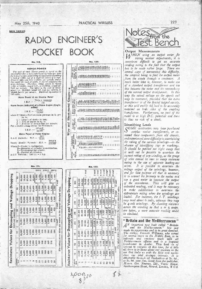
May 25Th, 1940 PRACTICAL WIRELESS
NEW SERIES
RADIO ENGINEER'S
POCKET BOOKNo. 119.
HORSE -POWERTie emit of work (Horse power) is based on the
assumption that a horse can travel 25 miles per hoarfors hours a. day, performing the equivalent of pullinga load of 150/b. out of a shaft hp means of a rope.Thus 2i miles an hour is 220ft. per minute, and atthat speed the load of 150/b. is raised vertically thesame distance. Therefore, 30015. would be raised110ft. or 3,0001b. raised lift., or 33,000/b. raised lft.
'high per miPute. The latter is the unit of horse-power. i.e., 33,00015, 'raised lft. high per minute, or:33,000 fool -lb. per minute. Electrical equivalent is
-7-:-13
Horse Power at an Electric MotorColts x Amperes
740Horse Power (Indicated) of a Stearn Engine (Single -
acting)PLAN
1.11.P. = 33,000 _
where P=iMean effective steam pressure in lb. persq:
L = _Length of stroke in feet.A = Area of piston in sq.-in.N = Number of revolutions per minute.
For a double-acting en dne the forMula is :2PLAN
"LP' - I33 1(
Horse Power of Petrol Engine;D2N
B.A.C. Formula : H.P. -D2SNR
Bendy Marshal Formula : H.P. =Where S ---Stroke in Centimetres.
D -Diameter of cylinder in centimetres.111, --Revolutions per minute.3,1 -Number of cylinders.
A.C.U. Formula : 100 c.c. = 1 h.p.
No. 121.
7103/1 PDAZ flung
1:10
C
O.C.
,.....,
---
--- ,---, cnt o ct8000660006666_ 6 6 0 06 6 6" e-; cTto cc c., ...I ,
o t_--..
6 0.,t,-,- ,n
o = oat as -ci ci ci
.., oir, _.,-, ,
..2
0a.00
oc o 0 0 0 0000000006 0? 0 0 06' c.--3 i-S .-41 6 4-3
0 0^0 ,c,. ci
O^5 6 50 0 ,m -1 ,-.
00O-
cc4;
ntCS4.II......0
-0
0 : 0 -, 0 0 00 '0 0 0 06 6 6 6 6 6O O ,ti 6 Cl in---t ot e-.
0 00 0 0,rt o tnCO CO" 'a
0 00 6 0,n o o,--1 ,..4 ,.3
.
,t.
C(c3 n00 4"C (c.,
.3.._.! o
F.::
---66.666666,66-..:1°43 '6 0 6 . 0 00 0 ° 0 0. °,.. 06 ..., 6 6 ii-- ca (sics., -i
. 0 00 °.. 0.as a-, as
0 00 ...'a-i
so....,,
2.TtL3 p0 0u -,!
0°,9
C 0 0 0 0 0 Cl 0 0888888888E88- -c = I. ,,, c, " " "
0 .0 C
- -NJ O
" ;-....,t.-).
s.0
4.-
CD
c c, c c c c c c -_, - c c-,,_, 0 C 0 ...... C 1 ,O .;74 0 0 S. 0 0 0 .(-, . ,. . N
0' 1.."; 1..1 ,7.1' G I ,-1 r -I
,,,,,
-.6.4,C3
,c'..c>
. ;=
=(1>5./
o o 0 o 0 o c c c 6 6..,.., 0 0 6 6 0 0 0 0 0 0 'a- s it -3 ..., iri, 6, 0 'a . . ,-.,-3 ,.:, i
o .,,, cc cc c., ,
c-,,
..`3
'J.,'
. 7, -tia
UCcd
44ul-
. . . . 0 0 0 0 0 0 0,-, E888888.7,;:,-.,`8?,
o, ,co ,t ,...., ,, -
'-,-,-E-i
0
Le g Et..c
No. 120.
e'',,.,,c., -N
-'
,<",-+
.,:,,;
iii i ii,SVZ7t,'RE:-Iong-5,Y>f2g7;'2,909,,, ,t--. co ot>at at trto..-Icit, mw ,n co we
..-,e'.,,,M.,.4 . 0.,,CON.N.0Nc,,cocnt,,,,,,,,t.,otocct-t-c-> 1 1 1 1 1 1
.to,,,opme...-1.,-.,..ocoo,mo,.,'.'''......''''iiIIIIIIIIIM''.5
F...o66c5dO,
,--0,-,,,,,,,..0bA
,"''''--'"IiililiiiIiiii'.-...!..Q.! ....
000cl
- ?.ioF,,,W4ici68,25.,L1-4n86,T,VS',,r,.., ,,,,,-,,,,,,c-S,,,,S:6,,,,,,c,,,,,,zcsic,iccic,i
61`'''
k
N,0tle
.NO,N,,..--,01,,,NM,COM.,,......,, F5KR-F,. . .
W ....s,,,,,,
=-1
,,,,,,c1,:,,,mcocnm,lows,aorn.,,,c,,,,H.co,pcvom,,..Lo.,,m,cii',1 c4.4,...1 -4-4666666.666666666S6
10 ,,,---il .
Cl.
N.0.MNIC.M.....,..O.NN,0C,.,,Q2,..,,V.,...NNNN*,,....°'.......°g...Q....C.
,
,...-:,...NC.,.. ,,,,,,"°''''°...'"'"Clr-... IIIIiillii
Z,1,, .--C,CC--4-.645.45V5',
& N.0,,N.,[-OCONCO,,41,' °'.4.c.,',.cl.C1,1,11 111111 -I I I I
'65 Z:X*,1-ii-iftC.PAC)Pq-,
'-'1 242`,P,r,=,`,2-cinciFt'in'2F.C.2
No. 122....,
--ci",'' '''' i-"-
..-, CO 00 ..* ,,,., Cl '0 00.0C0.0.0
0°0 0c 00 0. .0.CA ,
0 0 c0 c0 0 0kr; 0 0
00...00...,C..-.,
,c7
0,.0-00
,.-.."..c0.c6
,,.-_,-.
t-
5-2
-,'----'
0.-:0, .z....-
,..,
.,C.-'-' ,
120
o.:, == .-,-,,:;. ,,,,...:,
c - -=., = ."----s ..,?}: Ti:
5.,'.;tr:,..
,,..--..
--rt,_-1,
=c.-o
s.88'-.2, -
-ck:
0 '--
,
- Cs -o440
...A,
19
os
',:-.'
999,.0990 - 00 :5 0,
,rt t--r,
00 0 o.o.
occ. 6
cc-...7
8L-.
............
=---,
33-9"p..,-.....3 r'-'. "1,-3
.'".....,. ''-'
zt.-..
,?,
CO0.,-,..,.04VIV.C-P_
.1.-. . . ..C .-7., C' C`..
C".. ''''- S 01, ,.:A . 0ci 0 -4, cc,'-'
0C,
,-ci
-cC C
C'c, o,......
..
C",1-
----....._
.c.
'''''
='.--.
9,Hc,
.-,....,
C',.
"-j
i.,...!
Mt,
W'.'.
c 0 c 0 c. ,,,, ,-...
'."-'
0 0 .,--, c c
-
2,".., Zl'
"-.E, 2CI
1..04.4.1
0°
0 ....- 0. ,,, 0 _...-0 0 0 0,-- '6 . , -3,1 ,l, . ,7-1 :'5'.1
0-"0.0
'
0. c,. .,..::: ,
. ,,0' °
i
..' -
1
00,.,-..
z,-.' ,..,..,.,
'E--;
CD
3-el
.op
0 0O 0 0 0 0. c . . Lr.,
o 6 6' ,62 ,-:',-_, -1-.. 0.:, 0, -
o..,..,
,-;-
- -0 0 0,,,,.: ,,,.. ,-,i
0:i
--,..., a <3$
,-,
ti0.)
NtaVI
L, _G 1-,':
-I-
6o o o,ti t:i CI
....til
04
223
Output Measurements'HEN using an output meter for
testing receiver adjustments, pit issometimes difficult to get an accuratereading owing to the fact that the outputhas to be made rather large. There areseveral ways of overcoming this Agicully,the simplest being to feed the output meter
from the anode through a condenser. Amuch better idea is, however, to make useof a standard output tranyfOrmer and usethis between the meter and the secondaryof the normal output Iran: former. lit thisway the actual voltage on the speech coilmay he measured, provided that the extratransJO rmer is of the special tapped variety,as this will enable the Woad to be accurately -matched on both :ides of the couplingtransformer. Furthermore, 120 part of themeter is at hick. D.C.potential and thereis thus no risk of a shock,
Identifying LeadsSOME constructors may have purchased
surplus mains transformers, or re-moved these components front old chassis,and experienced some difficulty in ascertainingthe rating of the various windings-in theabsence of identifying tails or markings.It should be pointed out right away thatit will not be possible to ascertain thecurrent rating of any winding, as the gaugeof wire cannot be seen in mar?), instancesowing to the use of. separate leading -outwires. It is possible to ascertain thevoltage output of the windings, however,and for that purpose all that is necessaryis to connect the primag to the mains anduse a good meter to measure the outputof the secondaries. This will give anunloaded reading, and it may be necessaryto make calculations to ascertain theappropriate rating when the windings areloaded. For instance, the h. T. windingsmay read about 6 volts, whereas they maybe 4 -volt windings. By shunting resistorsacross the winding so that a or 3 amps.are taken, a more accurate reading couldbe obtained.
" Britain and the Mediterranean "AN important new book called " Britain
and the Mediterranean" has justmade its appearance and is in great demand.The author, Kenneth. Williams, who servedfor several years in the Middle East, is in.intimate and constant touch with allMediterranean affairs and is a frequentbroadcaster in. Arabic. This book -is ofinterest to everyone at this time, for it tellsall there is to know about our Ignition in the800 that links vs with the East and makesclear our vital strategic intere618. it 18
obtainable through all Booksellers at as. 6d.,or 3s. 9d. post free, direct .from the publisher,Messrs. GeO. NOW1le8, Ltd., Tower flou.,Southampton Street, Strand, L(»ule.n, W.C.2.
A.D6)0,e,
75 -

224 PRACTICAL WIRELESS
Open tThe Editor does not necessarily agree with the opinions expressed by his ,correspondents. All letters must be accompanied by the name and addressof the sender (not necessarily for publication).
A Good S.W. LogSIR, -Other enthusiasts may like tokJ know of my progress in one hobby -underthe auspices Of PRACTICAL WIRELESS.
I first began seven years ago and,. untilJanuary of this year, concentrated myenergies on the medium -wave band, tryingout many circuitsand suggestions appearingin P.W. Jneidentally, I have, filed allarticles of reference, value during the. lastseven years. TheSe, together with severalof the P.W. bookS, give me a good rdferenee-library. -
In .January Ibuilt in first short -waver,ear 0 -v -pen, -battery-operated, designedfrom articles appearing in P.W. Theconnections are soldered throughout. Theaerial is a home-made vertical copper -tubetype, 811. long and 25ft. high.
My log for the first twelve weeks of oper-ating, excluding French, Gorman, Italian,and Russian stations, is as follows. Theseare broadcast stations :
25 -metre band : SBP, LKQ,. HBO,CSW6, WPIT, WCBX, WRUW, MTCY,XGOY, VLQ2 (Sydney), ZPI4.(VillaRica),CXA ? (Montevideo). [This last is anexperimental transmission on 25 -metreband and I should say the wavelength isabout 25.7m.]
31 -metre band; CSW7, CS2VV-A4 EAQ,OFD, SBU, TAP, YUA., JZ1 (Tokyo),VLQ (Sydney), WGEO, CR7BE (LotirenoMarques), WGEA, WBOS, WCBX,WCAB,WRCA, and Radio Eireann. -
49 -metre band: FIVJ, SBO, YUB, Lahti,WCBX, and VP3BG (Georgetown).
You will observe that all. continents -arecovered and new stations are being loggedevery week so far.
.My only regret is that enlistment willpostpone my activities for the meantime,but I- hope to go on filing P.W. for manyyears to come. -Thank you for a fine paper.-E. A. COLLINS (Ashtead).
Novel Circuit -for a Crystal Setenclose a circuit for a crystal
set which, has proved very efficient. In my locality, the present broadcasting.arrangements are well received, but owingto the power of the " Overseas " trans-mission I have found that crystal setswill only separate the " Home" and Over-seas" with an acceptor wave -trap: .Aftermany tests with diffiJent condensers andcoils I find that this circuit gives me thestrength that I require plus the separationof the two stations.
The aerial coil is an adaptation of themedium -wave section of the coil used inthe " A.W." 150 -mile circuit. Wishingto use small components I decided to use a21in. diameter former and double thenumber of turns to 76, and use 30 SAN .G.instead of 28 S.W.G., as this was thenearest' size I .had. On trying it out Iincluded a .0005 tuning condenser, butfound that this was detrimental and actedonly as a volume control.
The wave -trap coil is the aerial windingof a coil shown on page 131 of PRACTICALWIRELESS, October 28th, 1939.
I trust that these particulars will be ofinterest to other readers who, like myself,
prefer to experiment with the. differenttypes of crystal detector circuits. Shouldanyone wish to write me regarding thiscircuit I shall be pleased, and if they willenclose a stamp their letters will be repliedto by return.--AnNotn S. LONG (2D,Hopwood Bank, Horsforth, Leeds).
_ .
Circuit diagram of Mr. A. S. Longscrystal set.Wave Trap Coil ; 60 turns. 30 S.W.G.. enamelledcopper wire on 6 former 1V5in. diameter. AerialDetector 76 turns .of 50 S.W,C. enamelledcopper wire on a former 2'f in. diameter. Crystaltap al 10 turns. Aerial tap at 40 turns. Variablecondensers preferably ganged, .0003 or .0005 mfd_The .0005 tuning condenser is not required,150 mile circuit, the wave -trap serves the same
purpose.
An Efficient Three -valve CircuitSilt; I have been taking PRACTICAL
WIRELESS for over a year now andfeel :I must write to express my pleasure
PROBLEM No. 401.
7
Solution to Problem No. 406.When Melville node the change in valves he should
also have modified the anode circuit of the detector, asan S.G. valve requires a much higher anode load than atriode. Accordingly, the simple transformer couplingfailed to provide a sultableinad for the valve and thusit gave very little more amplification than the triode.Ho should have used an-R.C. or resistance -fed trans-former coupling.
The following three readers successfully solvedProblem No. 309 and books have accordingly beenforWarded to them:A. Pick, 55, M(ddleton Street, Spring Rank, Hull.E. M. beard, 0, Alfred Street, Shrtwsbury.W. Whitfield, 11.114.T. City O. Florence. (10
London
BLACKhad a three -valve receiver which
suddenly ceased to function. He madetests with his volt meter and found that H.T.was in order. He next used a milliammeterand found that the output and detectorstages were pawing normal current, Liftwhen the meter was joined between the tcpcap of the ILE. valve and the lend he couldobtain no reading. He aS,7111Ind that the valvewas faulty and ordered another one. Wien
-plugged in the set still failed to work. Wherehad he gone wrong? Throe books will he
; awarded for .f he first three correct solutionsopened. Entries must Le nddressed to TheEditor, PRACTICAL WIRELESS, George Newnes,
; Ltd.. Tower. House, Southampton St reet.strand, London, W.C.o. Envelopes must hemarked Problem No. 4-01 and must heto reach this office not later than the first postoo.MoiolaV, May 271-11. 1940.
regarding the. fine performance of a receiver,the circuit of which was published in 'the" P.W. Encyclopaedia" andr also " SixtyTested Wireless Circuits" -both of whichI find most useful and instructive. - Theset is a simple straight three -valve batteryset (Det.-L.F. Pow.), and is transformercoupled. Tuning is extremely simple withthree plug-in coils. Incidentally, I have notadhered exactly to the components specified,and yet after a few improvements, suchas a wave -trap, etc., it works admirably.I get the Home Service, Forces Programmeand Overseas Service at remarkablestrength. .
-I .would like to. communicate -with- anyyoung reader about my own age -13- years.-A. H. IluaKILL (18, Raglan' Court,Curzon Crescent, Church Road, -'Willesden,N.W.10).
Dead SpotsQ d .1 ike to :wake a CorrectionkJ to my letter published in: PRACTICALWIRELESS, No. 399.
The times of transmissions in .Englishfrom 11C,IB are not altered- by the recentchange over to Daylight SaVing Time, inAmerica, and they remain .as previously,12 midnight -1 a -.m. and 3-4-G. FILLEITI, (Gosport).
Al4mc's Log from Wandsworth
SIR.,-I append my 14 me/8 log of
stations heard during the month OfApril in the hope of interesting other readers.The RX is ap 0-v-2 and antennmlate :
1. 66ft. indoor, N.W.-S.E.-S.W.-W.-E.2. 45ft. E. -W. under the eaves(of the roof.and 3. 16ft. V -beam directed, on Asia(N.E.). :
Fone and C.W. :AC4MI, CHI AR, lAS, 3CZ ;#,CO20Y,
2LY, 20Y, 5BA, 60M,- 7CS, 7CX,- 81\1P-;CX2CO, D6AWY, EA7A, 9BA,-; EK1AF,ES1E, 4G, 5C, 5D, 6E; 'HAIL 2P; 3B,.
0K, 7N, 8B, 8S, 8T; HH2HB, HI1P,3N, 5RC; IIKTG, 7 AA ; K6NYD, 01"LZ,LU4KO, 5CK ; LY1BE, 1DD, ICI,1J, 1MB ; LZ ID, OK3ID, :32N ;OQ5BF, PY1GJ, DIE, 2CK, 2ET,5AD; TGSJG, U3BM; 3BX, 3DS,5YH, 81L, 9MJ; UE2GB, 3KP, ' 3KQ;UK3AH, 1-V1ADM, BCX, ISB,;WC-, KJ,I, LPY, OR; W2AD, BCK,PBC, CRB, ECR, HFM, IXY; LBK,-
'LLB, MTC ; W3BNC, EOZ; EQZ, FAM,HFD. }KIN ; \V4AR\'V, DCQ, FUT ;W5AKZ, BEK, SMO, W6BGW, ITH,MRI3, MYO, NJV, PCV ; :W7ACD, EKA,GMV, HIA . (Oreg.); WSACY, BYR,CRA. CUO, -JSU, LA, NJP, PMP, RHP ;
W9AKI, DAY, ELK, NDA, TI; YU7AY,7LX ; YV1AQ, 1AV, 4AE, and 5ABE.
Station MTCY (" The Voice of Manchu-kuo ") has been heard at R9 (QSB to R5)on 11,775 1;c is, giving out news. in Englishfrom 22.00-22.15 B.S.T., and continuingwith a talk entitled " Prosperous Manchu-kuo " from 22.15-22.30, which is to becontinued every day !-LEONARD F. CROSBY(WalldSW01111).
Correspondents Wanted 1
A. G. E.AIII S, of 93, Dukes Avenue,New Malden, Surrey, would like to
get into touch with a reader who has.a copyof IV. M. for June, 1934.
D. S. Del ler,- of 24, Chadway, Becontrce,Essex, would like to get into touch withany reader concerning experiments with anH.F. receiver, having H.F. reaction with .aseparate triode valve.
May 25th, 1940 PRACTICAL WIRELESS 225
in replyqoiour letter
Superhet Design" I have purchased a surplus chassis
which contains a number of valveholders,components and wires. I also have a mainstransformer. The circuit which has beenused on the chassiS is obviously- a superhet,but my mains transformer is rated for twovalveS more than the chassis. I wonderif you could give me any idea as to the bestcircuit to build up.' I know you would not4e able to supply a blueprint, but the circuiton the chassis is obviously frequency changer,I.F., second detector, L.F. and- push-pull,and I am afraid I cannot see any suitable
'change to' suit my transformer. I mightmention -that I have plenty of valves.".1. W. R. (Oldhani).
THERE is some -difficulty in making achange in a circuit especially if much
wiring is in position. Further, it may notbe necessary to add valves to compensatefor.the high secondary rating of the trans-former. A simple bleeder resistance wouldenable you to dispose of the extra current.However, one change is apparent in thecircuit 'which, whilst using the extracurrent might also lead to better resultsand would at least give you more scopefor experiment. We refer to the use of aseparate oscillator valve and also a phaseinverting valve so that you could use R.C.coupled push-pull amplification. Thesechanges would lead to very little materialalteration in the circuit wiring or design,but would give improved results.
Direct -coupled Amplifier" I was interested in the recent direct -
coupled -amplifier design, and wonder ifsuch a scheme could be successfully em-p'.oyed in a push-pull amplifier. I wonderif you can supply any details in this con-nection. I might mention that I tried out thedirect -coupling idea some years ago andwas impressed, but think that push-pullwould give still better results."-L. F.( N. W.5. ).
CIAN amplifier of the type you mention has
been produced in America as a com-mercial proposition. Microphone or pick-up input is fed to the grids of two L.F.pentodes in the usual way and the twoanodes are taken direct to the grids of twobeam tetrodes. 300 volts is 'applied,through a 100,000 ohm resistance to eachinput anode and' output grid, thus givingapproximately 150 volts on the grid, andthe two output anodes are fed to an outputtransforrner in the usual way. The cathodesof the output valves are 170 volts positive,and the anodes 420 volts, the arrangementresulting in the grid actually being biasedto-- 20 volts. Perhaps these details wouldbe of interest to you. The input valves are6SJ77s- and the output valves 6146's.
U.S.W. TuningI have been experimenting with some
U.H.F. circuits and receivers, but must con-fess that I have not had much success.The main point seems to be in the way ofobtaining a really smooth reaction circuit,and although I have, tried,. most valves,even removing the base from one to try
and reduce losses, I am unable to get smoothresults. Could you help me in this con-nection ? "-C. P. S. (Wood Green).
WE assume that you are using a stan-dard arrangement, and in that
case you should attend.to the removalof the damping in the detector stage. Usea loose -coupled aerial, with a movableaerial coil so that coupling may be adjustedfor best results, and use tapping clips sothat not only the anode (reaction) point,but also the grid point may be adjustedfor the removal of damping. We do not
r- RULESIWe wish to draw the reader's attention to the
fact that the Queries Service is intended only./ for the solution' of problems or difficulties
arising from the construction of receivers! described in our pages, from articles appearingi in our -pages, or on general wireless matters.
We regret that we cannot, for obvious reasons-! (X) Supply circuit diagrams of complete
multi -valve receivers.(2) Suggest alterations or modifications of
I
receivers described in our contem-poraries.
(3) Suggest alterations or modifications tocommercial receivers.
r. (4) Answer queries over the telephone.(5) Grant interviews to querists.A stamped addressed envelope must be
Ienclosed for the reply. All sketches anddrawings which are sent to us should bearthe name and address of the. sender.
Requests for Blueprints must not be enclosedwith queries as they are dealt with by aseparate department.Send your queries to the Editor, PRACTICAL WIRELESS,
a George Newnes, Ltd., Tower House, Southampton Street,I Strand, London, W.C.2. The Coupon mast be enclosed
with every query.L1411104141=1.01.101 /4110.61.111.1i1141.004104140i041=Pii
know exactly what waveband you wish touse, but no doubt something on the abovelines will enable you to obtain the desiredresults.
H.F. By-passing"I send you 'a circuit of a receiver for
short -waves and should be glad if you couldexplain the H.F. by-pass arrangement, wherethey show a normal .1 mfd. H.F. decoupler,with a .0001 mfd. mica in series. You will seethat this occurs in several parts 'of thecircuit and I should like to know the reason."-G. R. (Farnborough).
THE arrangement is merely a safeguard,the mica condenser being capable of
withstanding a higher voltage load and thus,in the event of the tubular condensersbreaking down, the mains section will notbe damaged due to a short-circuit. Thereshould be no need to use the mica con-densers, provided that the other condensersare chosen with a suitable voltage rating.
Making Astatic Choke" I wish to make up a good H.F. choke
for a standard receiver, --but do not wish togo to the expense or trouble of making ascreened component. I believe it is possible toobtain a similar effect by a special form ofwinding, and if that is so, would you pleasegive me instructions for carrying' it out?_ Ihave plenty of ebonite rod, tube and wire." --M. B. A. (Radlett).
THE arrangement you refer to is known asan " astatic " winding,, and in it the
total winding is divided into two settions
which are wound in opposition. In thisway the fields cancel out. The simplestconstruction wquld be to obtain two shortlengths of your ebonite rod-say about2ins. in length and wind about 750 or 800turns of wire on each former,, taking carethat the windings on the two formersare in opposite directions. They are con-nected in series. Suitable wire would be36 S.W.G. enamelled.
Weak Output'" I have just completed a Mall A.C.
gramophone amplifier, but am disappointedwith the result. I used a 3 watt pentode anda good L.F. valve, with transformer couplingand a good make of pick-up. I have testedthe' voltages (H.T. and G.B.), and they arecorrect according to the maker's instructions.The speaker is a good one and has not hadmuch use. I should like some idea as towhere to turn, for improvement in thisinstance."-S. A. (fiord).
ALTHOUGH we have not seen atheoretical diagram and are without
quite a lot of data relative to the circuitwe think that the most likely, cause of thetrouble is that you have overlooked a funda-mental regarding design. The amplifieris probably working quite well and correctlybut by using an output valve rated at '3watts you have expected to get 3 wattsoutput. This does not necessarily follow, andyou will only obtain that output when thevalve is fully loaded. For that purposeyou would no doubt need a further stageof amplification between the two existingvalves. Your pick-up may be quite a goodone but giving a small output and thus theoutput valve is considerably underloaded.
r111.0.11011 -114M.0.041114111011.1.411...110.941.11. /011.041111104.114 Hone.%
REPLIES IN BRIEFThe following replies to queries are given in
abbreviated form either because of non-compliancewith Oils rules, or because the point raised is not ofgeneral interest.
%P.O.W. NOMA NMIPINIIM.1 PAM...M.i.1111.0.WIt110.1P.
J. H. (Bangor). Aluminium cannot be used in themanner indicated. Your main difficulty would be inmaking good contact as the material Is not easilysoldered. - -
S. P. (Manchester). The interaction is undoubtedlydue to the aerial positions. Try to move one of theaerials, and if it is not possible to obtain a very acuteangle, each aerial should be moved slightly to increasethe effect.
B. W. S. (Steyning). The two pentodes would bequite satisfactory except from the point of Nit* of -battery consumption.
T. G. (Heston). The burning of the wire in order toclean it has no doubt annealed the wire and may also
.
have resulted in some chemical deposit from anyinsulating material which was on the wire covering.
S. F.(11chester). The knobs may be obtained fromMessrs. Bulgin. 'Various patterns are available.
F. M. T. (Harrogate). We do not recommend theprocedure. A good S.W. converter is much better andwould be more reliable.
C. S. F. (Fareham). The cheaper component is, inthis case, preferable, as it has a lower D.C. resistance.
G. C. M. (Surbiton). Full details were given in theissue dated December 9th last.
H. W. J. (Aylesbury). 'Ordinary bell wire may he,used, hut the special stranded flex is mote suitable andhas a lower H.F. resistance.
F. R. D. (Gilmorton). Have you tried the standardarrangement ? We suggest you do this first to makecertain that the wiring is in ordet.
R. G. (Berwick). Use tinned copper wire, abontt,22 S.W.G. would be suitable, An article on 1.1wsubject will appear shortly.
H. B. E. (St. Athans): The box may be of aluminiumor wood covered with metal foil
L. D. (Carfax). We have not tested the modeland cannot therefore give you a criticism.
S. L. K. (Ilfracombe). Ordinary fabric is preferableas the metallic material may cause resonance orcoloration to -the reproduction, -
M. A. H. (Manchester, 20). The coil unit as wellas the tuning condenser may be transferred to the newSet as 'they are quite standard.1- 4111.0.1404/1111.11./1111
The coupon on page 228 must beattached to every query
ZANIMMHOP1/104104.14/4111.141111111.04=1.0411114 1.111.1.1.0.11.11111.01111.01A.

226PRACTICAL WIRELESS May 25th, 1940
Practical Wireless
BLUEPRINT SERVICEPRACTICAL WIRELESS No. of
Date of Issue. Bliferint-CRYSTAL SETS
Blueprints, 6d. each.[937 Crystal Receiver .. PW71rhe " Junior " Crystal Set .. 27.8.88 PW94
STRAIGHT SETS. Battery Operated.One -valve : Blueprints, 15. each.All -Wave Unipen (Pentode) .. -Beginners' One-valver 19.2.88The ' Pyramid " One -valuer (,
Pen) .. 27.8.38
Two-4-alve . Blueprint, Is.The Signet Two (D & LF) 24.9.38
Three -valve : Blueprints, 1s. each.Seleetone Battery Three (D, 2 LF
(Trans))Sixty Shilling Three (D, 2 LF
(RC & Trans))Leader Three (SG,'D, Pow) ..Summit Three (HF Pen, D, Pen)All Pentode Three (HP Pen, D
(Pen), Pen) .. 29.5.87Hall -Mark Three (SG, D, iow) .. -Hall -Mark Cadet (I), LF, Pen (RC)) 16.3.35F. J. Camm's Silver Souvenir (BF
Pen, D (Pen), Pen) (All -WaveThree) . .. 13.4.35Cameo Midget Three (D, 2 LF(Trans)) ..
1936 Sonotone Three -Four (PO?Pen, HF Pen, Westector, Pen)
Battery All -Wave Three (D, 2 LF(RC))
The Monitor (HT Pen, D, Pen) .. -The Tutor Three (HF Pen, D,Pen) 21.8.86The Centaur Three (SG, Tr, P) 14.8,87F. J. Camm's Record All -Wave
Three (HT Pen, D;Peu) - 31.10.36The " Colt " All -Wave Three (D,
2 LF (RC & Trans)) .. . 18.2.89The " Rapide " Straight S (V,2 LF (RC & Trans)) .. 4.12.37
F. J. Camm's Oracle All -WaveThree (HP, Det., Pen) .. 28.8.87
1938 " Triband " All -Wave Three(11F Pen, D Pen) .. 22.1.38F. J. Camm's " Sprite " Three(BY Pen, D, Tet) 26.8.88
The Hurricane "All -Wave Three
F.{(J. CommD
sP), PePosh-Sutton". 30.4.88
" PThree (HF Pen, D (Pen), Tet) 8.9.88
Four -valve : Blueprints, is. each.Sonotone Four (SG, D, LF, P)Fury Four (2 SG, D, Pen)Beta Universal Four (SG, D,
01. B)Nucleon Class B Four (SG,
(SG), LF, Cl. B)Fury Four Super (SG, SG, D, Pen)Battery Hall -Mark 4 (HF Pen,
D, Push -Pull)F. J. Camm's " Limit " All -Wave
Four (HF Pen, D, LF, P)" Acme " All -Wave 4 (HE Pen,
Admiral"LF,I. B)
The " Four (HF Pen,HT Pen, D, Pen (RC)) , .
Mains OperatedTwo -valve : Blueprints, 1s. each.A.C. Twin (D (Pen), Pen)A.C.-D.C. Two (SG, Pow)..Selectone A.C. Radiogram Two
(D, Pow)
Three -valve Blueprints, 1s. each.Double -Diode -Triode Three (HF
Pen, DDT, Pen)..D.C. Ace (SG D, Pen)A.O. Three (SG, D, Pen) . A.C. Lender (HF Pen, D, Pow) .
D.C. Premier (HF Pen, D, Pen ..Unique (HF Pen, D (Pen), PenArmada Mains Three (HE Pen, D,
Pen) ..F..1. Camm's A.C. All -Wave Silver
Souvenir Three (HT Pen, D, Pen)" All -Wave " A.C. Three (D, 2
LF (RC)). A.C. 1936 Sonotone (HF Pen, Rif
Pen, Westector. Pen) .. `..Mains Record Ail -Wave 3 (HP
Pen, D, Pen) ..Four -Valve : Blueprints, 1s. each.A.C. Fury Four (SG, SG, D, Pen)A.O. Fury Four Super (SG, SG, D,
Pen)A.G. Hall -Mark (HF Pen, 5,
Push -Pull)Universal Hall -Mark (BF Pen, D,
Push -Pull)
1.5.378.6.37
26.9.36
12.2.38
8.9.38
7.1.39
PWS1APW85
PW93
PW76
PW10
PW84APW85PW37
PW39PW41PW48
PW49
PW51
PW53
PW55PW61PW62PW64
PW69
PW72
PW82
PW78
PW84
PW87
PW89
PW92
PWPW11
PW17
PW34BPW340
PW48
PW67
PW88
- PW90
PW18PW31
PW19
PW23PW25PW29
PW350PW35BPW36A
PW33
PW50
PW51
PW56
PW70
PW20
PW34D
PW45
PW47
SUPERHETS.Battery Sets : Blueprints, is. each.
Superhet (Three -valve) .. 6,6,37 PW40F. J. Camm's 2 -valve Superhet PW62_
Mains Sets : Blueprints, 1s. each.A.C. Superhet (Three -valve) .. PW43D.C. £6 Superhet (Three -valve) PW42Universal £6 Superhet (Three -
F. J. Camm's A.C. Superhet 4 - PW59PW44valve)
F. J. Camm4's Universal £4 Super-
Qualitone Universal Four ..PW60het ..
16-.1.37 PW73Four -valve : Double -sided Blueprint, Is. Od.Push Button 4, Battery Model }Push Button 4, A.C. Mains Model 22.10.88 PW95
SHORT-WAVE SETS. Battery Operated.One -valve : Blueprint, 1s.Simple S.W. One-valver 23.12.89 PW88Two -valve . Blueprints, 1s. each.Midget Short-wave Two (D, Pen) PW38AThe `Fleet" Short-wave Two
(D (HF Pen), Pen) .. 27.8.38 PW91Three -valve : Blueprints, 1s. each.Experimenter's Short-wave Three
(SG, D, Pow) . PW30AThe Prefect 8 (D, 2 LF (RC andTrans)) . - PW63The Band -Spread S.V. Three(HF Pen, D (Pen), Pen) 1.10.88 PW88
PORTABLES.Three -valve:: Blueprints, 1s. each.F. J. Camm's ELF Three -valve
Parvo Flyweight Midget Portable PW65Portable (HP Pen, D, Pen) ..-(SG, D, Pen) .. 8.6.39
Four -valve : Blueprint, Is." Imp !! Portable 4 (D, LP, LF
(Pen))
MISCELLANEOUS.Blueprint, 1s.S.W. Converter -Adapter (1 valve) - PW48A
AMATEUR WIRELESS AND WIRELESS MAGAZINECRYSTAL SETS.
Blueprints, 6d. each.Four -station Crystal Set . 23.7.38 AW4271934 Crystal Set .. - AW444160 -mile Crystal Set .. - AW450
STRAIGHT SETS. Battery Operated.One -valve : Blueprint, 15.B.B.C. Special One-volver . AW887Two -valve : Blueprints, 1s. each.
Lucerne Minor (D, Pen)!..Melody
Ranger Two (D, Trans) .. AW388Full -volume Two (SG det, Pen) .. - AW892AW426A Modern Two-valvcr W31409
Three -valve : Blueprints, 1s. each.£5 5s. S.G.3 (SG, D, Trans) ..Lucerne Ranger (SG, D, Trans) .£5 5s. Three: De Luxe Version
(SG, D, Trans) . 19.6.34Lucerne Straight 'Three 1D, Rd,
Trans) . -Transportable Three (SG, D, Pen) -Simple -Tune Three (SG, I), Pen) June '33Economy -Pentode Three (SG, D,
Pen) .. , . Oct. '33" W.M." 1934 Standard Three
(SG, D,ee (Pen)
.. _ -£3 3s. ThrSG, D,'Trans) ..Mar. '341935 £6 Os. Battery Three (SO,
D, Pen). ..PTP Three (Pen, D, Pen) -Certainty Three (SO, D, Pen) . -illinitube Three (SG, D, Trans) . Get. '35All -Wave Winning Three (SG, D.,
Pen)
Four -valve : Blueprints, Is. 6d. each.65s. Four (SG, D, RC, Trans) . 2111' Four (2 SG, D, Pen)Self-contained Four (SO, D, LF
Class B) , . Aug. '33Lucerne Straight Four (SG, V,
LF, Trans) -£5 5s. Battery Four (11F, 1), 2 LF) Feb. '35The H.R. Four (SG, SG, D, Pen) -The Auto Straight Four (HF Pen,
HF, Pen, DDT, Pen) .. Apr, '36Five -valve : Blueprints, Is. 6d. each.Super -quality Five (2 HT, D, RC,
Trans) .. ,Class B Quadradyne (2 SG, D,
Class B)New Class B Five (2 SG, D, LF,
'Class B)
AW437WM271W11327
WM337
WM351WM354
WM371WM389WM393WM396
W11400
WM326
W M344
W51310
These Blueprints are drawn full size.Copies of appropriate issues containing descrip-
tions of these sets can in some cases be supplied atthe following prices which are additional to the costof the Blueprint. A dash before the Blueprint Numberindicates that the issue is out of print.
Issues of Practical Wireless ... 4d. Post PaidAmateur Wireless 4d. ,,Wireless Magazine .. 1/3The index letters, which precede the BltieprintNumber indicate the periodical in which the des-cription appears : Thus P.W. refers to PRACTICALWIRELESS, A.W. to Amateur Wireless. W.M. toWireless Magazine.
Send (preferably) a postal order to cover the costof the blueprint, and the issue (stamps over 6d.unacceptable) to PRACTICAL WIRELESS BlueprintDept.. George Newnes, Ltd.,Tower House, South-ampton Street, Strand, W.C.2.
Mains Operated.Two -valve : Blueprints, Is. each.Consoeleetric Two (D, Pen) A.C...Economy A.C. Two (D, Trans) A.C.Unicorn A.C.-.D.C. Two (D, Pen)Three -valve : Blueprints, Is. each.Home Lover's New All -Electric
Three (SG, D, Trans) A.C.Mantovani A.C. Three (HT Pen,
D, Pen) ..£15 15s. 1936 A.C. Radiogram
(HE, D, Pen) .. Jan. '38Four -valve : Blueprints, 1s. 6d. each.All Metal Four (2 SG, D, Pen) . July '33Harris' Jubilee Radiogram (HF
Pen, D, LF, P) May '35
AW403WM286W111394
1.W383
WM374
WM401
WM329
WM386
SUPER H ETS.Battery Sets : Blueprints, 1s. 6d. each.Modern Super Senior .. - WM375'Varsity Four , . Oct. '35 'VVM395'The Request All- Waver . .. June '36 wm4071935 Super -Five Battery (Superhet) - WM379Mains Sets : Blueprints, 1s. 6d. each.Heptode Super Three A.C. .. May '34 W11359" W.M." Radiogram Super A.C. - W31366
PORTABLES.Four -valve : Blueprints, 1s. 6d. each.
PW77 Holiday Portable (SG, D, LF,Class B)
Family Portable (HT, D,Trans)
PW86 Two 311' Portable (2 SG" VTyers Portable (S(1:13, 2 Trans)::
AW393
AW447
WM363WM367
SHORT-WAVE SETS. Battery Operated.One -valve : Blueprints, Is. each.S.W. One-valver for America 15.10.38 AW429Rome Short -Waver - AW452Two -valve : Blueprints, Is. each.Ultra -Short Battery Two (SG det,
Pen) . . Feb. '36 WM402Home-made Coil Two (D, Pen) AW440Three -valve : Blueprints, ls. each.World -ranger Short-wave 3 (D,
RC, Trans) .. - AW 355Experimenter's 5 -metre Set (I),Trans, Super-regen) . .. 30.8.34 AW438The Carrier Short -waver ('SG, D, P) July '35 WM390Four -valve : Blueprints, 1s. 6d. each.
A.W. Short-wave World-beater(HF Pen, ll, RC, Trans) . - AW438Empire Short -waver (SG, D,
AW412 Trans) .. - WM3] 3AW422 Standard Four -valve Short -waver(SG, D, LF, P) 22.7.39 WE1383AW435 Superhet : Blueprint, 1s. 6d.
Simplified Short-wave Super .. Nov. '35 W11397
Mains Operated.Two -valve : Blueprints, ts. each.Two -valve Mains Short -waver (D,
Pen) A.C." W.M." Long -wave Converter ..Three -valve : Blueprint, Is.Emigrator (SG, D, Pen) A.C.Four -valve : Blueprint, 1s. 6d..Standard Four -valve A.C. Short -
waver (SG, D, RC, Trans) ..
13.1.40 AW453WM380
- WM352
MISCELLANEOUS.S.W. One -valve Converter (Price
AW370 Enthusiast's Power Amplifier (1/6) - WM387AW421 Listener's 5 -watt A.C. Amplifier(1/6) - W111392WM331 Radio Unit (2v.) for W11392 (11-) Noe. '35 W11398Harris Electrogram battery am-
WM350 pllfler (1/-)wmgai De Luxe Concert A.C. Electro-WM384 gram 0-/-) . .. Mar. '38 V(M403New style Short-wave 'idapterWM404
W11383Trl e Charger (e.a.) .. .. AW462.Short-wave Adapter (1/-).. .. - AW458Superhet Converter (1/-) .. .. - AW457B.L.D, .C. Short-wave Converter '36 W11405altar (1/-)'Juneun'36 W31406T Short-wave Con=
- WM391
.
WM399
WM408
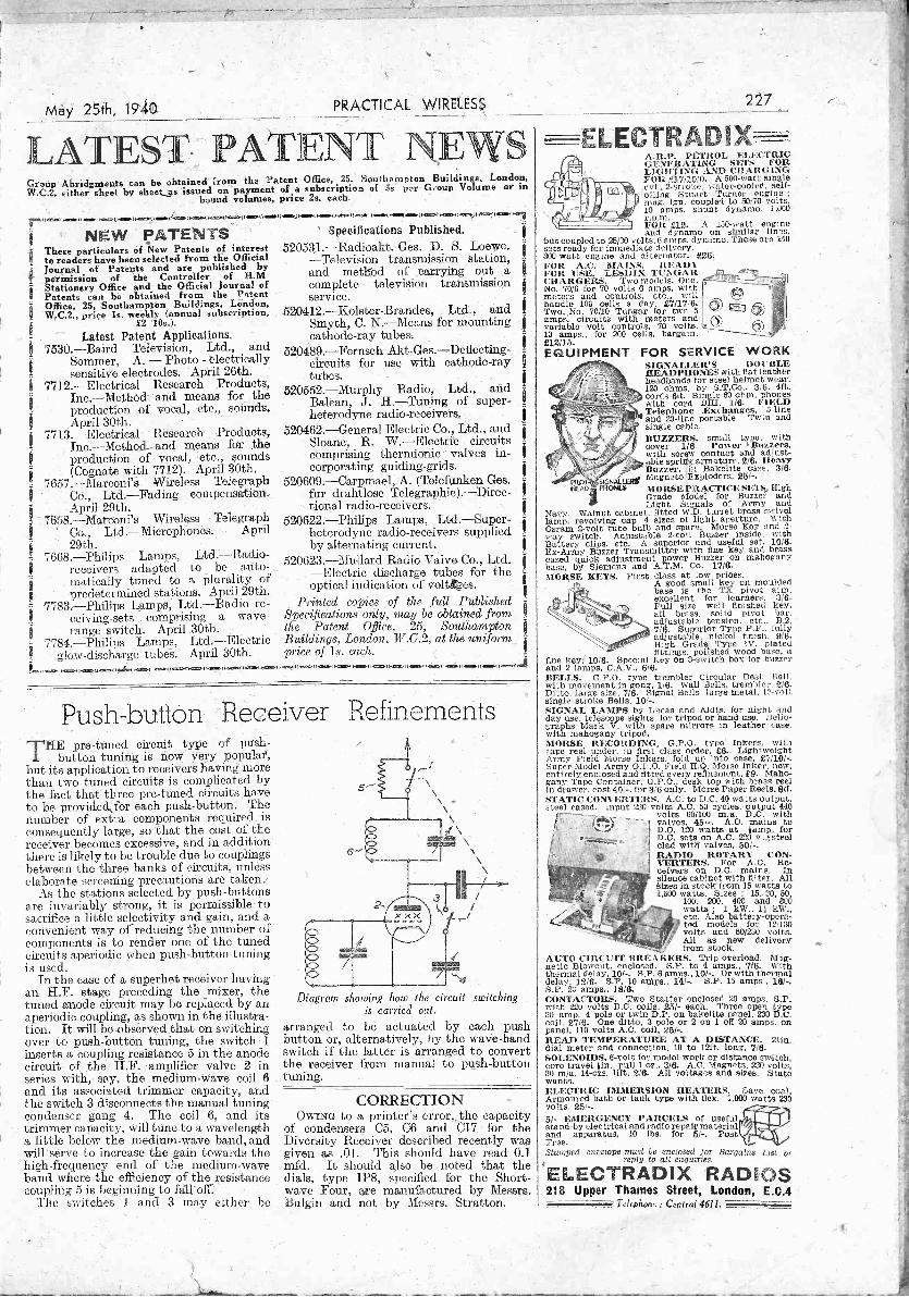
May 25th, 1940 PRACTICAL WIRELESS
Group Abridgments can be obtained from the Patent Office, 25, Southamp on Buildings, London,W.C.2, either sheet by sheetjs issued on payment of a subscription of 5s per Group Volume or in
bound volumes, price 2s. each.
rr114111.M.1).1=1.1100011.01.00i1141I011.41011411110.11.1/0114=011...0.IHM.11.011.1M114,4.m...M.1.= owoamoo.r.-ms
NEW PATENTS Specifications Published.
NewtTohreesaeaperasrtiiiacuelair.seonfePatentsroniinterest 520531.-Radioakt.-Ges. P. S. Loewe.
cted -Television transmission station,
Latest Patent Applications.7530. -Baird Television, Ltd., and
j Sommer, A. - Photo - electricallysensitive electrodes. April 26th.
7712. -Electrical Research Products,Inc. -Method and means for theproduction of vocal, etc., sounds.April 30th.
7713. -Electrical Reseaxch Products,Inc.-MethosL-and means for the
I production of vocal, etc., sounds(Cognate with 7712). April 30th.
7657.-Marconi'S Wireless TelegraphI Co., Ltd. -Fading compensation.
April 29th.7658.-Marconi's Wireless Telegraph
td. -Microphones. AprilCo.,,29th.
7668. -Philips Lamps, Ltd. -Radio -receivers adapted to be auto-matically tuned to -a plurality ofpredetermined stations. April 29th.
7783. -Philips Lamps, Ltd. -Radio re- Printed copies -of the, full Publishedceiving-sets comprising a wave- Specifications only, may be obtained from !
i range switch. April 30th. the Patent Office. 25, Southampton7784. -Philips Lamps, Ltd. -Electric Buildings, London; W.C.2, at the uniform
! glow -discharge tubes. April 30th. price of Ls. each. I
ese...11041.11.11dirtf1.1111.0.61.114=1.1.11111011.0.11..MIN14111041...1.0=q).=.MMOINNO.1.1111.11M11.0.00.4i
j Journal of vPatents and are published by and method of carrying out a,11 permission of the Controller of WM
Stationery Office and the Official Journal of complete television transmissionPatents can be obtained from the Patent - service.Office, 25, Southampton Buildings, London,W.C.2.,price Is. weekly (annual subscription, 520412.--Kolster-Brandes, Ltd., and .1
£2 10s.). Smyth, C. N. -Means for mounting- cathode-ray tubes.
520489.-Fernseh Akt-Ges.-Deflecting-circuits for use with cathode-raytubes. _
520552. -Murphy Radio, Ltd., andBalean, J. H. -Tuning of super-heterodyne radio -receivers.
520462. -General Electric Co., Ltd., andSloane, R. W. -Electric circuitscomprising thernaionic valves in-corporating guiding -grids.
520609.-Carpmael, A. (Telefunken Ges.fur drahtlose Telegraphie).-Direc-tional radio -receivers.
520622. -Philips Lamps, Ltd. -Super-heterodyne radio -receivers suppliedby alternating current.
520623. -Mallard Radio Valve Co., Ltd.-Electric discharge tubes for theoptical indication of voltotes.
DU.S Dutton ReceiverTHE pre -tuned circuit type of push-
button tuning is now very nopular,but its application to receivers having morethan two tuned circuits is complicated bythe' fact that three pre -tuned circuits,haveto be provided,for each push-button. Thenumber of extra components required isconsequently large, so'that the cost of thereceiver becomes excessive, and in additionthere is likely to be trouble due to couplingsbetween the three banks of circuits, unlesselaborate screening precautions are taken.
As the stations selected by push -buttonsare invariably strong, it is permissible tosacrifice a little selectivity and gain, and a,convenient way of reducing the number ofcomponents is to render one of the tunedcircuits aperiodic when push-button tuningis used.
In the case of a superhet receiver:havingan H.F. stage preceding the mixer, thetuned anode circuit may be replaced by anaperiodic coupling, as shown in the illustra-tion. It will be observed that on switchingover to push-button timing, the switch 1inserts a coupling resistance 5 in the anodecircuit of the H.F. amplifier valve 2 inseries with, say, the medium -wave coil 6and its associated trimmer capacity, andthe switch 3 disconnects the manual tuningcondenser gang 4. The coil 6, and itstrimmer capacity, will tune to a wavelengtha little below the medium -wave band, andwill serve to increase the gain towards thehigh -frequency end of the medium -waveband where the efficiency of the resistancecoupling 5 is beginning to falloff.
The switches 1 and 3 may either be
Refinements
Diagram showing how the circuit switchingis carried out.
arranged to be actuated by each pushbutton or, alternatively, by the wave -bandswitch if the latter is arranged to convertthe receiver from manual to push-button
CORRECTIONOWING to a printer's error,, the capacity
of condensers C5, C6 and C17 for theDiversity Receiver described recently wasgiven as .01. This should have read 0.1mfd. It should also be noted that thedials, type IP8, specified for the Short-wave Four, axe manufactured by Messrs.Bulgin and not by Messrs. Stratton.
FOR SERVICE WORKSIGNALLER'S DOUBLEHEADPHONES with flat leatherheadbands for steel helmet wear.120 ohms. by S.T.Co., 3,6. 4ft.cords 6d. Single 60 ohm. phoneswith cord D131, 118. FIELDTelephone ExChanges, 5 -lineand 20 -line portable. Twin, andsingle cable.BUZZERS, small type, withcover, 1/6- Power 'Buzzers,with screw contact and adjust-able spring armature, 2/8. HeavyBuzzer, An Bakelite ca.se, 3/6.
PICII
siGNAtwat Magneto Exploders, 25/,14-AD PRONGS MORSE PRACTICE SETS, High
Grade Model for Buzzer andLight Signals of Army and
Navy. Walnut cabinet, fitted W.D. turret brass swivellamp. revolving cap, 4 sizes of light aperture. WithOsram 2 -volt tube bulb and spare. Morse Key and 2 -way switch. Adjustable 2 -coil Buzzer inside, withBattery clips. etc. A superior and useful set. 1016.Ex -Army Buzzer Transmitter with fine key and brasscased quick adjustment power Buzzer on mahoganybase, by Siemens and- A.T.M. Co. 1716.MORSE KEYS. First class at low prices.
A good small key on mouldedbase is the TX pivot arm,excellent for learners, 3/6.Full size well finished key.all brass, solid pivot bar.adjustable tension, etc., B.2,7/8. Superior Type P.F., fullyadjustable, nickel finish, 916.High Gradei Type IV. platedfittings, polished wood base, a
tine key; 10/8. Special Key on 3 -switch box for buzzerand 2 lamps. C.A.V.. 6/6.BELLS. G.P.O. type trembler Circular Desk Bell.with movement in gong, 1/6. Wall Bells, trembler. 2/6.Ditto, large size. 7/8. Signal Bells large metal. 12 -voltsingle stroke Bells, 10/-.SIGNAL LAMPS by Lucas and Aldis, for night andday use, telescope sights. for tripod or hand use. Helio-graphs Mark V. with spare mirrors in leather case,with mahogany tripod.
227
ELECTRADIX-A.R.P. Ph:TROL ELECTRICG EN Ell AT ING SETS FORLIGHTING AND CHAR INGFOR £17110'0. A 500 -watt singlecvl., 2 -sit cose water-cooled, self -oiling Stuart Turner engine ;mug. ign. coupled to 50/70 volts.10 amps. shunt dynamo. 1,000r. p.m.FOR £12. A 150 -watt engineand dynamo on similar lines, -
but coupled to 25/30 volts, 0 amps. dynamo. These are 240sets ready for immediate delivery.300 -watt engine and alternator, £28.FOR A.C. MAINS. HEADYFOR. USE. LESDI TUNGARCHARGERS. Two models. One,No. 70/6 for- 70 volts 6 amps, withmeters and controls, etc., willhandle 100 cells a day. 011716.Two, No. 70/10 Tungar for two 5am circuits with meters andvariabps. le volt controls, 70 volts,10 amps., for 200 cells, bargain,£12/15.EQUIPMENT
MORSE RECORDING, G.P.O. type inkers, withtape reel under. in first class order, £6. LightweightArmy Field Morse Jokers, fold up into case, £7/10/-.Super Model Army G.P.O. Field H.Q. Morse Inker. new,entirely,enclosed and fitted every refinement, £9. Maho-gany Tape Container, G.P.O. desk top with brass reelin drawer, cost 401, for 3/6 only. Morse Paper Reels, 8d.STATIC CONVERTERS. A.C. to D.C. 40 watts output,steel cased. Input 230 volts A.C. 50 cycles, output 440
volts 60/100 m.a, D.C. withvalves, 451-. A.C. mains toD.C. 120 watts at lamp, forD.C. sets on A.C. 220 v..listeelclad wits valves. 50/-.RADIO ROTARY CON-VERTERS. For A.C. Re-ceivers on D.C. mains. Insilence cabinet with filter. AllSizes in stock from 16 watts to1,600 watts. Sizes : 15. 30, 60,
100. 200, 400 and 800watts ; 1 kW., 11 kW.,etc. Also battery -opera-ted models . for 12/130volts and 60/230 volts.All as new deliveryfrom stock
AUTO CIRCUIT BREAKERS. Trip overload. Mag-netic Blowout, enclosed. S.P. to 4 amps., 7/8. Withthermal delay, 10/-. S.P. 6 amps., 10/-. Or with thermaldelay, 12/8. S.P. 10 snips., 14/-. S.P. 15 amps.. 16/-.S.P. 20 amps., 1818.CONTACTORS. Two Stetter enclosed 20 amps. S.P.with 220 volts D.C. coils, 25/- each. Three open type30 amp. 4 pole or twin D.P. on bakelite panel, 230 D.C.coil. 27/6. One ditto, 3 pole or 2 on 1 off 20 amps. onpanel, 110 volts A.C. coil, 25/-.READ TEMPERATURE AT A DISTANCE. 211n.dial meter and connection. 10 to 12ft. long, 7/6.SOLENOIDS, 6 -volt for model work or distance switch,core travel lin. pull 1 oz., 3/6. A.C. Magnets, 230 volts.30 m/a. 14-ozs. lift, 2/6. All voltages and sizes. Statewants.ELECTRIC IMMERSION HEATERS. Save coal.Armoured bath or tank type with tiox. 1.000 watts 230volts. 25/,6/- EMERGENCY PARCELS of usefulstand-by electrical and radio repair materialand apparatus, 10 lbs. for 5/-, PostFree.Stamped envelope must be enclosed for Bargains List or
reply to all enquiries.
ELECTRADIX RADIOS218 Upper Thames Street, London, E.C.4
Telephone : Central 4611.

228 PRACTICAL WIRELESS May 25th, 1940
Get back that PUNCHin your Set ! with the D.C.
AV °MINORReini Trade Mart
ELECTRICAL MEASURING INSTRUMENT
This precision -built moving -coil D.C.instrument, with 13 ranges covering0-120 rn/A, 0-600 volts, and 0-3megohms, provides adequate testingfacilities for checking valve perform-ance, batteries and power units, etc.It reduces trouble -tracking to itssimplest terms. In case with instruc-
tion booklet, leads,interchangeabletesting prods andcrocodile clips.
BRITISHMADE
Voltage Current0- 6 v 0-340 v. 0. 6 Tialaps.0- 12 v. 0-300 v. 0- 30 miaiiirs.0-120 v, 0-600 v. 0-120 m/amps.
Resistance0-10,000 ohms,0-60,000 ohms.0-1,200,000 ohms.0-3 megohms.
Write for fullydescriptive leaflet.
Sole Proprietors Manufacturers:-Automatic Coil Winder & Electrical Equipment Co., Ltd.,Winder House,Donglas St.,London,S.W.1. 'Phone: Victoria 340417
ARMSTRONGApologise for delay in delivery of some models,this unfortunately has been unavoidable owing tothe present great eilt:ulty in obtaining rawmaterials.
MODEL AW38. 8 -valve All,wave Super-heterodyne chassis. This All -wave Radiogramchassis has resistance capacity coupled push-pulloutput capable of handling 6 watts, and gives goodquality reproduction on both radio and gramo-phone, for an economical price of 8 gas. Plus,.)% war increase.
Armstrong Push-pull Speaker to match AW38chassis, £1 : 1 :0. Phis 5% war increase.
We suggest Model AW38 together with matchedspeaker at £9 ; 9 : 0, plus 5% war Increase, com-plete, represents the most outstanding value on,the market to -day
PAPER RATIONINGWe are reluctantly compelled to charge 6d. towardsthe cost of our Illustrated Catalogue in future,which gives full details of our complete range.
Write for your copy to -clay F
ARMSTRONG MAN FG. Co.WARLTERS ROAD, HOLLOWAY, LONDON, N.7
(Adjoining Holloway Arcade)'Phone NORth 3213
Classified AdvertisementsCABINETS
A CABINET for Every Radio Purpose. SurplusCabinets from noted makers tinder coat of manu-facture. Radiogram Cabinets from 30/-. Undefiledtable, console and loudspeaker cabinets from 4/6.Inspection invited.H. L. SMITH AND CO., LTD., 289, Edgware Road,W.2. Tel: Pad. 5891.
LITERATURENEW Edition. American Amateur Relay LeagueHandbook. 500 pages of up-to-the-minute technicalinformation, 7/- post free. 1940 Jones Handbook ;approximately 700 pages dealing with every aspect ofShort-wave Radio, 8/6, post free.-Webb's Radio, 14,Soho St., London, W.I. 'Phone : Gerrard 2089.
LO9DSPEAKER REPAIRSLOUDSPEAKER repairs, British, American, anyMake: 24 -hour service, moderate prices.-SinclairSpeakers, Pulteney Terrace, Copenhagen Street,London, N.1.
REPAIRS to moving coil speakers. Cones/coilsfitted or rewound. Fields altered or wound. Pricesquoted, including eliminators. Pick-ups and speakertransformers rewound, 4/6. Trade invited. Guaranteedsatisfaction. Prompt service.L.S. Repair Service, 5, Bannon Grove, London, S.W.12.Battersea 1321.
MISCELLANEOUS
PRINTING. -1,000 Billheads, 3s. 9d. ; Memos, Cards,etc-. Samples free. - Creteway Press, 21, Buxted,Sussex.
MORSE EQUIPMENTFULL range of Transmitting Keys, Practice Sets,Oscillators, Recorders and other Radio TelegraphApparatus, designed and manufactured by T. R.McElroy, World's Champion Telegraphist. Sole dis-tributors : Webb's Radio, 14, Soho Street, London,W.1. 'Phone : Gerrard 2080.
MORSE TRAINING
WIRELESS Code Courses. "Book of Facts" Free.-Candler System Co. (L.0.), 121, Kingsway, London,W.C.2.
NEW LOUDSPEAKERS3A00 Speakers, P.M. and energised lit,. to 14in. hi-eluding several Epoch 18111.-Sinclair Speakers,Pulteney Terrace, Copenhagen Street, Londtin, N.1.
PUBLIC APPOINTMENTS
AIR MINISTRY.AERONAUTICAL INSPECTION DIRECTORATE.Vacancies exist for unestablished appointments asExaminers in the Genetal Engineering, \\yr andInstrument Branches. -
QUALIFICATIONS.All candidates must have good general education, beable to read drawings, understand specifications, usemicrometers and other measuring instruments.(a) Applicants for the General Engineering -Branchmust have had practical experience in an engineeringworks. An elementary knowledge Of materials testingis desirable.(b) Applicants for the Instrument Branch must haveknowledge of physics and training in light engineeringOr instrument making. Candidates with knowledge ofoptical instruments are also required.(c) Applicants for the WIT Branch must have practicalknowledge of .W/T And electrical equipment withtechnical training in radio communication equalto City and Guilds final examination standard.ACCEPTED candidates will undergo a period oftraining in inspection as applied to the above subjects,not exceeding three calendar months, and will bepaid £3 10s. Od. weekly during training. Subsistenceallowance of £1 is. Od. weekly (hiring training ispayable to married men normally residing outsidethe training area. On successful completion of training,Candidates will be appointed as Examiners at a salaryof 2246, if 25 years of age or over, with a correspondingreduction of £12 per annum for each year -under 25 onjoining (payable monthly in arrear) if service is satis-factory, and must be prepared to serve in any part.of the United Kingdom.NORMAL age lithits 23 to 00.CANDIDATESshould indicate on their applicationsfor which vacancy they wish to be considered-a,-borc.APPLICATIONS must be made ort Form 780, copies ofwhich can be obtainea on application, by postcardonly, to : The Inspector -in -Charge, A.I.D. TrainingSchool (LC.S./REC. 51),. Brandon Steep, Bristol, 1.
SPADES.For Evty Purpose
smE111, No. 414 .Large, No. 415 . 2d.Heavy Wiring. No 416 3d.
Keyhole, No. 418 ... 2d.Hook, No-. 419 ;.. 2d.Usu 1 colours and engravings
British Mechanical Productions Ltd.I, Church Road, Leatherhead, Surrey.
WE SUPPLY LATEST MODELS OF
ARMSTRONGQUALITY CHASSIS ONEASY TERMS
WRITE FOR FULL DESCRIPTIVE LIST APlk TERMS. PROMPT DELIVERY, CARR. PAID.
LONDON RADIO SUPPLY CO.," WINDEN," ARDINGLY RD.,BALCOMBE,
SUSSEX .(Evacuation Address).
SPECIAL OFFERSPARTON 5 -Valve Press Button RadioAny 7 stations on Press Button. Walnut Cabinet.Provision for Pick-up and Extension Speaker,4 watts Output with negative feed back, Multi-stage Superhet, A.V.C. For A.C. mains only.Guaranteed Perfect Reception. Few only. OriginalPrice 29.19'.6. Our Price 44.5.0. Carriage paid.LONDON CENTRAL RADIO STORES,23 Lisle Street, W.C.2. Gerrard 2969
r1101143M(1.1010110(14.1(m(110 ( 1000FREE ADVICE BUREAU
COUPONThis coupon is available until June 1st, 1940 1.
! and must accompany all Queries and Hints.I PRACTICAL WIRELESS 25/5/1940.
istpeosm.hotHelost.ero,...(.....41.msosat.Mifi
Turn Your SurplusComponents Into Cash
Those components for whichyou have no further use can beturned into cash through theclassified columns of "PracticalWireless." Readers' adver-tiseinents are inserted at tJlespecial rate of Id. per word
(minimum charge I/-).Send your advertisement with P.O. to :-Advertisement Manager, " PracticalWireless," Tower House, Southampton
Street, London, W.C.2.
19-36 CALL-UPPost coupon now for details of ourHome -Study Radio Courses and learnhow you can qualify for better, pay in awireless section of the Army or Air Force.
T. & C. RADIO COLLEGEPFairfax House, High Holborn, W.C.I.
(Post In unsealed envelope, id. stamp.)Please send full details of your Postal Tuition
-
I NAME
I ADDRESSP.5.
May 25th; 1940 PRACTICAL WIRELESS iii
RADIO MAP AND GLOBE
WEBB'S Radio Map of the World enables you tolocate any station heard. Size 40" by 30" 2 colour heavyArt Paper, 4/6. Limited supply on Linen, 10/6.WEBB'S Radio Globe -superb 12" full -colour model.Radio prefixes, zones, etc. Heavy oxydised mount.Post Paid, 27/0.-Webb's Radio, 14, Soho Street,London, W.I. 'Phone : Gerrard 2089.
READERS' BARGAINS
GALVANOMETER, high resistance reading, patentapplied for, compact, complete, battery, guaranteed,10/6.11obley. The Drive, Wellingborough.
TROPHY 3. A.C., 6-550 metres, new March, perfect,nearest. £5/15/-.-Wishart, 9, Tankerville Terrace,NeweaStle-on-Tyne.
RADIOGRAM, good tone and working order, also all -wave table receiver. Must he good and reasonable
ice. -Roberts, Rural Structures, Amersham.
BROWN'S " A " 4,000 ohm EarphoneS, :30s., alsovarious valves, components; write stating require-ments. Wanted, 450v. transformer, Webley Air Pistol.Binoculars. Exchanges.- Wimbush, _Pdshopsworth,Bristol.
WANTED, D.C. AvoiNi inor, good condition. Write,stating price. -J. G. Picot, 18; Castle Road, Luton,Chatham, Kent.
CONSTRUCTORS' Surplus Components For Sale.Speakers, Valves, Coils, etc. Cheap and genuine.Please, state requirements. Stamp. -134, 01(1 Shore-ham Road, Southwick, Sussex.
HALLICRAFTER Sky -champion, as new, used lb.per week only. Owner joins Services, :S14.-0, ElizabethAvenue. Christchurch, Hants.
RECEIVERS AND COMPONENTS
GALPIN'S ELECTRICAL STORES.BRAND new Ex-G.P.O. Multi -contact Relays, smalltype, 1,000 x 1,000 coil resistance, 5/-. Ditto, 7,000r bins resistance, fitted 2 blades, :3/6 each, post 40.Useful for remote control, etc.MAINS Transformers. Input 200/240v., out I2v.at 3/4 amps, Useful model trains, L.T. rectifiers,etc. 9/6, post free.MAINS Transformer, 200/240v. input, 100v. at 100watts output, for American sets. 8/6 each, post 9d.SILVERTOWN Horizontal Galvanometers, jewelled
- movements, 5/- each, post Gd.HIGH Voltage Transformers, useful for all test workor television. Input 200/240v., output 5,000 and7,000v. output, 6/6 each, post 1/-.MAINS Chokes, 30 hy.' 120 inja., 150 ohms resistance,3/6 each, post Od. Ditto, 30 hy., 250,m/a., 7/6 each,post. Od. L.T. Choke, .5 hy., 11 amps., 3/6 each.ELECTRIC Light Check Meters, for sub -lettings,garages, etc. - 200/250v. 50 cy. 1 -ph., supply 5, 10 or20 amps., 6/- each, post a /-.P.14. Public Address Horn Speakers. Complete withpower transformer handle. 15/20 watts. Size, 40in.high. 30in. flare. Price, 75/-, Ca's,. Packing 5/-.WESTON and E. Turner first -grade 2in. Movin,Coil Milliamp. Meters, 0 to 50, 20/- each.
75, Lee High Rd., Lewisham, London, S.E.13.
SOUTHERN Radio's Bargains.ALL Guaranteed. Postage Extra.5/- Parcel of useful Components, comprising Con-densers, Resistances, Volume Controls, Wire, Circuits,etc. Value 25/-. 5/- per parcel.15/- Service Man's Component Kit. Electrolytic.Condensers, Volume Controls, Resistances, Tubular,Mica, Paper Condensers, Valve Holders, etc. 120articles contained in strong carrying case, 9" x 7" x 7",15/- the Kit.21/- Small Trader's Parcel of Components. 150Articles comprising all types Condensers, ValveHolders, Resistances, Chokes, Coils, Wire, etc. Value85/-, 21/- the parcel.5/- 100 Wire -end Resistances, assorted capacities.
and 1 watt, 5/- per 100.ORMOND Loud -speaker Units, 2/6; Crystal Sets,5/6; Westeetors Type W2, 2/6; Crystal Detectors,2/- ; Crystals, Gd. ; Marconi V21 Valves, Oil. " P.O."Microphones on Stand, for use with any receiver, 5/-;Telsen W'349 Iron -core Midget D.R. Coils, 5,6 MorseTapping Keys, 3/-; Buzzers, 1/6.2/- Tool or Instrument Carrying Cases, ex Govern-ment Stock ; Wood .0" x 7" x 7", 2/-.SOUTHERN Radio, 46, Lisle Street, London, W.C.Gerrard 6653.
RADIO CLEARANCE, LTD. All lines previously adver-tised still available from stock. Look out for startlingbargains in coming issues.RADIO CLEARANCE, LTD., 63, High Holborn, London,
W.C.1. Telephone: HOLborn 4631.
PREMIER RADIONEW PREMIER S.W. A.C.
RECEIVER KITIn response to many requests, we have now pro-duced an A.C. version of the popular PremierShort Wave SG3 Kit. Complete Kit of Partswith drilled chassiS, all components, Plug-inCoils covering 13-170 metres, 4 valves and fullinstructions and circuits 84/10/-. Completelywired and tested, 85/10/-.
Send for full detailsPREMIER SHORT-WAVE BATTERY -OPERATED
KITS for OVERSEAS NEWSIncorporating the Premier 3 -Band S.W. Coil. 11-86Metres without, coil changing. Each -Kit is completewith all components, diagrams, and 2 -volt valves.3 -Band S.W. 1 -Valve Kit, 14/-. 3 -Band S.W. 2 -Valve Kit, 22/6.
DE LUXE S.W. KITSComplete to the last detail, including all Valvesand coils, wiring diagrams and lucid instructionsfor building and working. Each Kit is suppliedwith a steel Chassis and Panel and uses plug-inCoils to tune from 13 to 170 metres.1 Valve Short -Wave Receiver or Adaptor Kit 20/-1 Valve Short -Wave Superhet Converter Kit 23/-1 Valve Short -Wave A.C. Superhet Converter
Kit .. 26/32 Valve Short -Wave Receiver Kit.. .. 29/-3 Valve Short -Wave Screen Grid and Pentode
Kit .. 69/ -
SPECIAL OFFER. ROTHERMEL PIEZOBRUSH CRYSTAL PICK-UPS. New JuniorP.U. with arm, 19/6. Standard S.8. Model witharm, 29/6. P.U, head only, De Luxe Model, 19/6.
Special Offer of Record Auto -Changer Units forA.C. Mains by famous manufacturer. Play 8records. Latest type Magnetic Pick-up, Auto -stop, Start and Rejector. Limited number onlyat 84/19/6, Carriage Paid.A.C. GRAMO UNITS, comprising Motor andPick-up, Auto Stop and Speed Regulator 52/6.MAINS TRANSFORMERS. Manufacturers' surplus.All brand new and Guaranteed.Input 110 v. and 220 v. A.C. Output 325-325 V.,120 m.a. 6.3 v., 2-3 amps., 5 v. 2 amps., C.T.,7/6 each. Input 230 v. A.C. Output 325-325 v.,75 m.a., 5 v. 2 amps., 6.3 v. 2-3 amps. C.T., 6/6each. Input 100-250 v., 300-300 v. 60 m.a. 4 v.5 a. C.T., 4 v. 1 a., 6/11.PREMIER BATTERY CHARGERS for A.G.Mains. Westinghouse Rectification complete andready for use. To charge 2 volts at ?s, amp., 11/9 ;6 volts at 72- amp., 19/- ; 6 volts at 1 amp., 22/6 ;12 volts at 1 amp., 24/6 ; G volts at 2 amps., 37/6.
REPLACEMENT VALVES FOR ALL SETSEUROPA MAINS VALVES. 4 v., A.C. 'types,A.C./H.L. A.C./L., A.C./S.G. A.C./V.-M.S.G.,A.C./H.P., A.C./V.H.P. (5 -pin) all 5/3 each.A.C./H.P., A.C./V.H.P. (7 -pin), 7/6. A.C./Pens-.H., 7/6 ; A.C./P.X.4, 7/3 ; Oct. Freq. Changers,
8/6 ; Double Diode Triodes, 7;6 ; 350 v. F.W.Rect., 5/6 ; 500 v. F. W. Rect., 6/6 ; 13 v..2 amps.Gen. Purpose Triodes, 5/6 ; H.F. Pens and Var.-Mu H.F. Pen., Double Diode Triodes, Oct. Freq.Changers, 7/6 each. Full and Halt -Wave Rectifiers,6/6 each.TRIAD HIGH GRADE U.S.A. VALVES, all typesin stock: Standard tubes 5/0 each. Octal Basetubes, 6/6 each.IVIORSE PRACTICE KEYS. -Brass movement onBakelite base, 3/3. General purpose Morse keys,smooth action, heavy contacts, 5/10.MOVING COIL SPEAKERS. All complete withOutput Transformer. Rola bin. P.51's, 12/6;8in..P.M.'s, 16/6 ; 10in. P.M.'s, 22/6 ; G12 P.M.'s,66/-. Energised Models. Plessey, 8111., 7,500ohm field, 7/6 ; 750 ohm field, 7/6 ; G12 Energised,1,250 or 2,500 ohms, 59/6.PREMIER Short -Wave Condensers all -brassconstruction, with Trolitul insulation. 15 mmf.,1/9 ; 25 muffs 1/10 ; 40 mint'., 2/- ; 100 mmf.,,2/3 ; 160 mmf., 2/7 : 250 mmf.,, 2/11.Coil Formers, 4- and 6 -pin, plain or threaded,1/2 each.UTILITY Micro Cursor Dials. Direct and 100 : 1
Ratios, 4/3,LISSEN Dual Range Screened Coils, medium andlong waves, 2/9 each.Orders 5/- and over sent Post Free. Under 5/ -please add fid. postage. All enquiries must be'accompanied by 2jd. stamp.
YOU MUST HAVE APREMIER 1940 CATALOGUE
111 PAGES . . . PRICE 6d. plus postage, 2!d.GET YOUR COPY TO -DAY ;
ALL POST ORDERS TO : Jubilee Works, 167Lower Clapton Road, London, E.5. Amherst 472:CALLERS TO : Jubilee Works, or our NEW
PREMISES, 169, FLEET STREET, E.C.4.Central 2533 .
or 50 High Street, Clapham, S.W.4. Macaulay 2311
117
RECEIVERS AND COMPONENTS
HIGH Grade Step-down Transformers 200/250v. 4v.4 amp., 4v. amp., suitable for Model Trains, etc.0/6 each.TOGGLE Switches, fid. ; Ex-R.A.F. 1 mfd. condensers,2,000 v. D.C. working, size gin. x Sin., 2/3. Plug andJack, open circuit, 1/6; 7- and 9 -pin chassis valve -holders, 3d.; 100 ohm LA,. Chokes, 45 m.a., 2/3 ;80-1 Mike Transformers, 1/9 ; Now Boxed 3 -gangCondensers, 2/8 ; Negative Feria -Back Chokes, 1/-,LONDON CENTRAL RADIO, 2:3, Lisle Street, W.C.2.Gerrard 2909.
5/- BARGAIN PARCEL comprising Speaker Cabinet,2 Drilled Chassis, condensers, resistances and manyother useful components. Worth U. Limitednumber. Postage 1/ -.--Bakers Selliurst Radio, 75,Sussex Road, South Croydon.
COULPHONE RADIO, Gaimshaw Lane, Ormskirk.Collaro A.C. Gramophone Motors, 12in. turntable,27/6. With pickup, 45/-. Crystal pick-ups, 22/6.Rola 0.12 Speakers with transkirmers, 1,250 ohms,52/6. P.M., 65/, Guaranteed American valves, 4/0,Octal, 5/6. 331 per cent. discount en Record BritishTypes. Latest Double Demi, O gus. 2)d. stampfor Lists.
VAUXHALL. -All goods previously advertised arestill available ; send now for latest price list, free. -Vauxhall Utilities, 163A, Strand, W.C.2.
DENCO ".Pocket Two " midget dry battery receiver,U/15/0. Ideal for present comfit -ons. Send for details.-Warwick Road, Clacton, Essex.
BANKRUPT Bargains. Brand new 193900 models,makers' sealed cartons, with gitarantees, at less30% to 40% below listed prices ; also Midgcts,portables, car radio. Send 21,(1. stamp fur lists. -Radio Bargains, Dept. P.W., 201-3, Lichfield Road,Aston, Birmingham.
TUITION
PRACTICAL Postal Courses, radio television, testequipment design, trade -test coaching for R.A.F.posts, I.P.R.E. and 1.W.T. exams. ; booklet free. -Secretary, I.P.R.E., 3, Shirley Road, London, W.4.
YOUNG MEN (15-20 years) urgently needed to trainas Radio Officers for the Merchant Navy ; militaryexemption obtainable ; short training period ; lowfees ; boarders accepted. Write or call for full par-ticulars, Wireless College, Calmore, Southampton,or Wireless College, Colwyn Bay.
BOOKS
YOU need this war atlas when you read the newspapersor listen to the wireless bulletins. " Newnes Compre-hensive \Var Atlas" will make the progress of theconflict understandable in all its aspects. 8 pages ofwar maps, including the Scandinavian countries,Western Front, Balkans, and all countries whosefrontiers adjoin or are near those of I lie belligerents.With war strengths of the Armies, Navies, and AirForces of the Nations. -Of all newsagents and book-sellers, ls. 0d. net, or by post Is. Oil. from the BookPublisher, George Newnes, Ltd., Tower House.Southampton Street, Strand, London, W.C.2,
KNOW what to do before the doctor comes. -Learnfront the new book, "First Aid For The Householder,"and your knowledge may he, the means of saving a life.Deals in simple language with all kinds of injuriesand their treatment, war -gases, shock, and the minorailments Of everyday life.- Clearly illustrated. -Of all booksellers, is. Oil. net, or by post ls. Oil. fromthe Book Publisher, George Nownes' Ltd., TowerHouse, Souihanipton Street, Strand, London, IV ('.2.
reemran
Ibis unique Handbooks how 3 the easy way to
secure A M C . E . ,
A. Al. I. A.13., A. M I.W. T.,'A.N1.1.1t.E., and similar qualifica-
tions. WE UARANTEE-" NO PARS -NOFEE." Dotal s are given of over 150 Diploma Coursesin all branches of Civil, Mech., Elec., Motor. Acre,Radio and Television Engineering, 1111111(1111g,Draughtsmanship. Tracing. Inspection. Govern-ment Employment, etc. Write for tills enlighteningHandbook to -day FRI/F and Cost free.,lien with Radio knowt,dge can obtain alit act too posts in Me Brt otorsBritish Institute of Engineering Technology,409, Shakespeare House, 17. 18, 19,841:Mord PI., W.1

Says thisRADIO
SERVICEMANAGER
A BIG OPPORTUNITY
TO -DAY
WITH the call-up affecting many thousands of Radio engineers,and wireless playing an increasing part 'on the Home Frontand in the Services, Radio Service Managers are at their wits'end to -day to keep pace with the work in hand.Husbands and brothers, who normally knew enough about wirelessto diagnose and correct simple troubles of the family set, are awayin the Forces, and women send for service men when their set" goes wrong."Servicing is only one of the many busy branches off modern radio,and the industry provides a golden opportunity for youths leavingschool and others to learn a remunerative trade. One may studyit by reading the following important radio books, which form acomplete sequence of authoritative instruction in radio practiceto -day. If you are a father, consider radio for YOUR son. Getthe whole set of books, or singly in the order given.
The following practical books are by F. J. CAMM(Editor of Practical Wireless)
THE PRACTICAL WIRELESSENCYCLOPAEDIA
Wireless Terms and Definitions stated and explainedin concise, clear language. 392 pages. Over 500illustrations. 7s. 6d. net. (By post 8s.)EVERYMAN'S WIRELESS BOOK
A Radio Consultant for all, explaining the Operation,Upkeep and Overhaul of all types of WirelessReceivers. 200 illustrations and diagrams.53. net. (By post 5s. 6d.)
SIXTY TESTED WIRELESS CIRCUITSModern circuits of every type. Diagrams and in-structions for assembling and wiring. Details ofcomponents and notes on operation.
3s. 6d. net (By post 4s.)PRACTICAL WIRELESS SERVICE MANUALA complete work on the testing and servicing of alltypes of wireless receivers. Packed with information.With over 220 illustrations. 288 pages.
6s. net. (By post 6s. 6d.)NEWNES' SHORT-WAVE MANUAL
Deals thoroughly with the problems underlying thedesign of short-wave apparatus, the special circuitswhich yield the best results, and designs for receiversbased on those circuits. 5s. net. (By post 5s. 6d.)WIRELESS TRANSMISSION FOR AMATEURSCovers fully and clearly the whole field of wirelesstransmissions. With 120 illustrations.
3s. 6d. net. (By post 4s.)WIRELESS COILS, CHOKES AND
TRANSFORMERSFor every home constructor. 126 illustrations.
3s. 6d. net. (By post 4s.)Of all Booksellers, or by post from the Publishers?
George Newnes, Ltd. (Book Dept.), Tower House, Southampton Street,Strand, London, W.C.2.
George Netvizes, Lid.
I RADIOTRAININGMANUAL 7!p.w.
1.12.14104.1=10-(14M1.11.1P,11111.(1160.1)..z.:,-atesoson. )41.142;11111.11.104..041.1,11.01,It
INVALUABLE TO ALL ELECTRICAL ENGINEERS
COMPLETEELECTRICAL
ENGINEERINGSTUDY the information contained in this great new worke7 and you will add considerably to your earning capacityin the electrical engineering world ! COMPLETE ELEC-TRICAL ENGINEERING is offered to you at a price you canafford to pay. It is a complete library-a ready reference tothe thousand and one applications of present-day electricalengineering. Its contents are absolutely comprehensiveand deal with everything you can possibly want to know--from Electrical Power Supply to Talking Picture Equipment
;from the Wiring of Modern Flats to Electrical Timing Instru-ments ; from Emergency Storage -Battery Systems to TestingElectrical Machinery ; from Lift Operation and Control toGarage Electrical Testing Equipment ; from Time Switchesand Time -Delay Devices to Electrical Welding Plant; fromRefrigeration to Electric Meters and Cookers, etc.It is impossible in this space to include details of the 160Sections, but you can examine COMPLETE ELECTRICAL
ENGINEERING at our expense, in order that you may realiseit is the very work you have been looking for.
Over 3,000 Pages of Exclusive,Practical, Worth -while Information.Over 2,590 Action Photographs,Plans, Tables and Calculations. 63EXPERT CONTRIBUTORS. SpecialChart Case with 48 Data Charts.2 YEARS' POSTAL ADVISORY
SERVICE
Complete in8 volumes <,M
SENT ON7 DAYS'
APPROVALPOST PAIDNo obligationto purchaseFill In
Coupon Below
"PRACTICAL WIRELESS" EXAMINATION FORMTo HOME LIBRARY BOOK CO. (George Newnes, Ltd.),Tower House, Southampton Street, London, W.C.2.
Please send me, carriage paid, for seven days' FREEexamination, " COMPLETE ELECTRICAL ENGINEER-ING," complete in eight volumes. It is understood that Imay return the work on the eighth day after I receive it, andthat there the matter ends. If I keep the books I will sendyou on the eighth day a First Payment of 5/-, and, beginning30 days after, twenty furthermonthly payments of 5/- each,thus completing the purchase price.
(Price for Cash on the eighth day, 100/-.)Name
Address
OccupationState if Householder
State age in wordy Date(P.W. 25540.)
_1George Newnes, Ltd.PubEshed every Wednesday by GEORGE NEW -1,.g, LIMITED, Tower House, Southampton Street, Strand, London, W.C.2, and
Printed in England by THE NEWNES & PEARSON PRINTING CO., LTD., .Exmoor Street, London, W.10. Sole Agents for Australia and NewZealand : GORDON & GOTCH, LTD. South Africa : CENTRAL NEWS AGENCY, LTD. Practical Wireless can be sent to any part of the world.postfree, for 17s. 80. per annum; six months, 8s. 100. Registered at the General Post Office as a newspaper and for the Canadian Magazine PGA.