how to: cxhydronic systems - bcxa.org
TRANSCRIPT

How To: Cx Hydronic Systems
David SellersSenior Engineer, Facility Dynamics Engineering

AIA Quality Assurance
The Building Commissioning Association is a Registered Provider with The American Institute of Architects Continuing Education Systems (AIA/CES). Credit(s) earned on completion of this program will be reported to AIA/CES for AIA members. Certificates of the Completion for both AIA members and non-AIA members are available upon request.
This program is registered with AIA/CES for continuing professional education. As such, it does not include content that may be deemed or construed to be an approval or endorsement by the AIA of any material of construction or any method or manner of handling, using, distributing, or dealing in any material or product.
Questions related to specific materials, methods, and services will be addressed at the conclusion of this presentation.
2

Learning Objectives
1. Attendees will be able identify field clues that provide insights into opportunities to improve the performance of central plant equipment and the systems they serve and deduce the design intent for the systems.
2. Attendees will be understand that it is possible to develop field clues into meaningful savings estimates based on basic information available in the field and an application of fundamental principles to that information and the clues they have identified.
3. Attendees will have a practical understanding of the operating principles behind a decoupled, variable flow, primary/secondary hydronic system.
4. Attendees will recognize the interactive nature of HVAC systems and the utility systems and equipment serving them and that the physical configuration of the systems and equipment need to support the design intent.
3

Class Material Location
The slides, Sketchup Models and other supporting information for the class can be found at:• http://tinyurl.com/NCBC2016WorkshopI will keep them there for a while and anything that we develop in class or that I mention having as a resource that I can share will be put up there in a “Follow Up” folder so you can pull the information back after classAbout using my spreadsheets and other resources:• They are my tools vs. tools I developed to be used by others• Use at your own risk; I provide them as a resource for you to use as
a starting point• You still need to understand how it works and fix it if it doesn’t work
for you
4INTRODUCTION AND OVERVIEW

Agenda
1. Overview of key commissioning skills with a focus on field observation and “Obvious Indicators”
HOW TO: CX HYDRONIC SYSTEMS 5
Gary Larson Goat in the Clouds Cartoon Here

Agenda
1. Overview of key commissioning skills with a focus on field observation and “Obvious Indicators”
2. Visit a central chilled water plant to practice using obvious indicators to identify opportunities to improve performance, save resources, and understand how the building and its systems work
HOW TO: CX HYDRONIC SYSTEMS 6

An EBCx Approach, but Technically, its All the Same
On going operation &
commissioning
Retro-commissioning
New construction
commissioning
Technical steps and techniques
Field Experience
Design Intent
HOW TO: CX HYDRONIC SYSTEMS 7

NC Cx vs. EBCx
Operating Requirements
Heat Transfer Equipment Selections
Process Parameters
System Configuration
Owner’s Project
Requirements
Distribution Equipment Selections
Installation Documents
Assembled Building
Physical Configuration
Loads
Construction Project
HOW TO: CX HYDRONIC SYSTEMS 8

NC Cx vs. EBCx
Operating Requirements
Heat Transfer Equipment Selections
Process Parameters
System Configuration
Owner’s Project
Requirements
Distribution Equipment Selections
Installation Documents
Assembled Building
Physical Configuration
Loads
Construction Project
HOW TO: CX HYDRONIC SYSTEMS 9

NC Cx vs. EBCx
Operating Requirements
Heat Transfer Equipment Selections
Process Parameters
System Configuration
Owner’s Project
Requirements
Distribution Equipment Selections
Installation Documents
Assembled Building
Physical Configuration
Loads
Construction Project
HOW TO: CX HYDRONIC SYSTEMS 10

NC Cx vs. EBCx
Operating Requirements
Heat Transfer Equipment Selections
Process Parameters
System Configuration
Owner’s Project
Requirements
Distribution Equipment Selections
Installation Documents
Assembled Building
Physical Configuration
Loads
Construction Project
For more on NC vs. EBCx functional testing see the proceedings from the session Kent Barber and I did together at NCBC 2013;http://tinyurl.com/NCBC2013KentBhttp://tinyurl.com/2013NCBCDavidS
HOW TO: CX HYDRONIC SYSTEMS 11

Ten Key Commissioning Skills
1. Be Able to Benchmarking and Perform Utility Analysis
2. Be able to Scope a Facility
3. Be Familiar with Fundamental Principles and HVAC
4. Understand and Apply the System Concept
5. Be Able to Perform Data Logging and Trend Analysis
6. Be Familiar with Functional Testing Techniques
7. Be Familiar with Data Analysis Techniques
8. Be Familiar with Basic HVAC and Energy Calculations
9. Be Familiar with Cost/Benefit and Return on Investment Calculations
10. Develop a Competency with Control Systems
Visit http://tinyurl.com/EBCxSkills for more on why these skills matter
HOW TO: CX HYDRONIC SYSTEMS 12

Ten Key Commissioning Skills
1. Be Able to Benchmarking and Perform Utility Analysis
2. Be able to Scope a Facility
3. Be Familiar with Fundamental Principles and HVAC
4. Understand and Apply the System Concept
5. Be Able to Perform Data Logging and Trend Analysis
6. Be Familiar with Functional Testing Techniques
7. Be Familiar with Data Analysis Techniques
8. Be Familiar with Basic HVAC and Energy Calculations
9. Be Familiar with Cost/Benefit and Return on Investment Calculations
10. Develop a Competency with Control Systems
Visit http://tinyurl.com/EBCxSkills for more on why these skills matter
Be Familiar with Fundamental Principles:1. Loads2. Centrifugal Machines3. Piping Systems4. Refrigeration and Cooling
Equipment5. Heating Equipment6. Variable Flow Water Systems7. Duct Systems8. Economizers9. Makeup and Exhaust Systems10.Variable Air Volume Systems
HOW TO: CX HYDRONIC SYSTEMS 13

Ten Key Commissioning Skills
1. Be Able to Benchmarking and Perform Utility Analysis
2. Be able to Scope a Facility
3. Be Familiar with Fundamental Principles and HVAC
4. Understand and Apply the System Concept
5. Be Able to Perform Data Logging and Trend Analysis
6. Be Familiar with Functional Testing Techniques
7. Be Familiar with Data Analysis Techniques
8. Be Familiar with Basic HVAC and Energy Calculations
9. Be Familiar with Cost/Benefit and Return on Investment Calculations
10. Develop a Competency with Control Systems
Visit http://tinyurl.com/EBCxSkills for more on why these skills matter
Our focus for the session today
HOW TO: CX HYDRONIC SYSTEMS 14

Scoping – On Site
Looking for Obvious Clues• Do things make sense?
• Should the outdoor air dampers be open or closed given the current conditions?
• Should the chilled water coil be active given the current conditions?
• Are things running when they don’t need to run?
Gary Larson Goat in the Clouds Cartoon Here
HOW TO: CX HYDRONIC SYSTEMS 15
Scoping – On Site
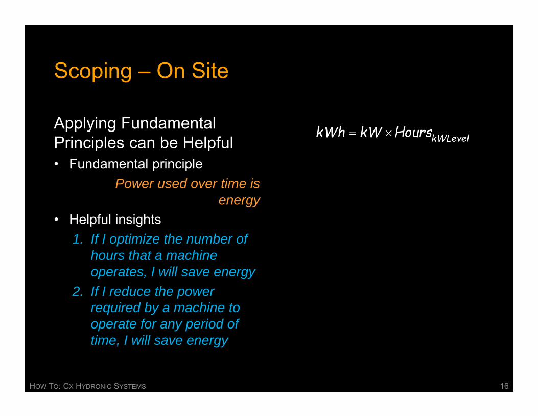
Applying Fundamental Principles can be Helpful• Fundamental principle
Power used over time is energy
• Helpful insights1. If I optimize the number of
hours that a machine operates, I will save energy
2. If I reduce the power required by a machine to operate for any period of time, I will save energy
HOW TO: CX HYDRONIC SYSTEMS 16

Scoping – On Site
Applying Fundamental Principles can be Helpful• Fundamental principle
Pump power is a direct function of the flow and head
produced• Helpful insights
1. If I reduce the head or the flow, I will reduce the power required
2. If there is unnecessary head or flow that I can eliminate, I will reduce the power required
HOW TO: CX HYDRONIC SYSTEMS 17

Scoping – On Site
Applying Fundamental Principles can be Helpful• Fundamental principle
Head required varies as the square of the flow
• Helpful insights1. If I cut the flow in half the
pressure required to produce it will be cut to 25% of what it was for a fixed system
2. For a fixed system, pump power will vary in proportion to the cube of the flow
HOW TO: CX HYDRONIC SYSTEMS 18
Scoping – On Site
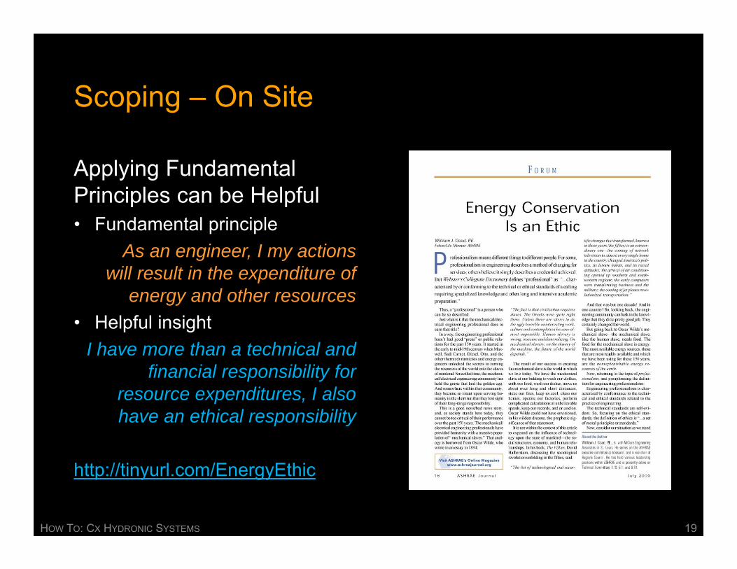
Applying Fundamental Principles can be Helpful• Fundamental principle
As an engineer, I my actions will result in the expenditure of
energy and other resources• Helpful insight
I have more than a technical and financial responsibility for
resource expenditures, I also have an ethical responsibility
http://tinyurl.com/EnergyEthic
HOW TO: CX HYDRONIC SYSTEMS 19

Scoping – On Site
Applying Fundamental Principles can be Helpful• Fundamental principle
The fundamental goal of most building systems is to provide
an environment that is safe, clean, comfortable and
productive • Helpful insight
If, in the name of efficiency and sustainability, I do something that
makes the built environment unsafe, unclean, uncomfortable or
unproductive, then I have done a disservice
HOW TO: CX HYDRONIC SYSTEMS 20

Common Findings for CHW Systems
1. Equipment in “Hand”2. Throttled pumps3. Throttled pumps with VFDs4. Short circuits across the
mains5. Non-optimized set points6. Non-optimized sequencing7. Interactive parallel pumps8. Physical piping configuration
issues9. Poor cooling tower flow
distribution
10. Concurrent cooling tower make-up and over-flow
11. Misapplication of the pump and fan affinity laws
12. Control system lags13. Issues with loads served by
the planta. Part load performanceb. Mismatch between load
and plant ∆tc. Coil performance
characteristicsd. Control valve issuese. Economizers not working
HOW TO: CX HYDRONIC SYSTEMS 21

Looking at a Few Examples
Equipment in “Hand”• Very common• Potential big savings for a low cost
(maybe)
HOW TO: CX HYDRONIC SYSTEMS 22

Looking at a Few Examples
Equipment in “Hand”• The Applicable Fundamental
Principles
HOW TO: CX HYDRONIC SYSTEMS 23

Looking at a Few Examples
Equipment in “Hand”• Evaluating the savings with field
data …
The pump is probably throttled to design conditions
The pump nameplate probably reflects design conditions
HOW TO: CX HYDRONIC SYSTEMS 24

Looking at a Few Examples
Equipment in “Hand”• Evaluating the savings with field
data …... operator insights …
The operators typically can provide key information like hours of operation and when they need to start chillers vs. using economizer cooling
The operators typically can provide key information like hours of operation and when they need to start chillers vs. using economizer cooling
HOW TO: CX HYDRONIC SYSTEMS 25

Looking at a Few Examples
Equipment in “Hand”• Evaluating the savings with field
data …... operator insights …
... and climate data
Bin data, TMY data or hourly weather data from a national climate resource can provide a sense of how many hours a year exist at the conditions associated with different operating modes
HOW TO: CX HYDRONIC SYSTEMS 26

Looking at a Few Examples
Throttled Pumps• Very common• Many ways to achieve the savings
with pros and cons to each that will be equipment and site specific
HOW TO: CX HYDRONIC SYSTEMS 27

Looking at a Few Examples
Throttled Pumps• The Applicable Fundamental
Principle
HOW TO: CX HYDRONIC SYSTEMS 28

The System Concept
Fundamental to Understanding how Equipment and Machinery will be Integrated and Interact with Other Machines, Systems, Building Occupants, Building Processes, and the Climate
HOW TO: CX HYDRONIC SYSTEMS 29

Its Not Just an Air Handling Unit … …It’s an Air Handling System
HOW TO: CX HYDRONIC SYSTEMS 30

Its Not Just an Air Handling Unit … …It’s an Air Handling System
HOW TO: CX HYDRONIC SYSTEMS 31

The Physical Configuration Needs to Match Design Intent
The piping plan
HOW TO: CX HYDRONIC SYSTEMS 32

The Physical Configuration Needs to Match Design Intent
The piping isometric
HOW TO: CX HYDRONIC SYSTEMS 33

Typi
cal
AHU
Typi
cal
AHU
SD
TDV
Chi
ller 1
N
o VF
D
SD
TDV
Chi
ller 2
VF
D &
HG
SD
TDV
SD
TDV
The Physical Configuration Needs to Match Design Intent
The piping system diagram
Which is the easiest to use to communicate or understand how a system works and perform diagnostics?
HOW TO: CX HYDRONIC SYSTEMS 34

Let’s Go to the Plant
HOW TO: CX HYDRONIC SYSTEMS 35

A Few Bottom Lines
• Cooling systems are major players in terms of delivering a safe, comfortable and productive built environment
• Cooling systems are major consumers of the resources we are blessed with
• Cooling systems are dynamic, complex, and highly interactive
• Understanding the details behind the equipment and systems provides insight into how to design them for efficient, sustainable operation
• Understanding the details behind the equipment and systems provides insight into how to make them work properly and keep them that way
HOW TO: CX HYDRONIC SYSTEMS 36

One Thing Leads to Another
Piping Network
Load
Pump
Expansion tank and make up water
Make-up, Blow-down, and Water Treatment
Evap
orat
or
Con
dens
er
Expansion Device
Compressor
Water Chiller
Pump
Piping Network
Piping Network
Cooling Tower End
Use
HOW TO: CX HYDRONIC SYSTEMS 37

The Savings Ripple Out Beyond the Plant
Switch Gear
MCC
TransformerkWh VFD
Pump Efficiency LossesVFD Efficiency Losses
Distribution System Losses
Transformer Losses
More Distribution System Losses
Motor Efficiency Losses
HOW TO: CX HYDRONIC SYSTEMS 38

Fossil Fuel Base Generation Has Ripple Effects
• Most plants run on electricity • A lot of electricity comes from fossil fuel
‒ The current heat rate for fossil fuel plants is about 10,000 Btu/kWh‒ A kWh is 3,413 Btu
Conservation of mass and energy says that most of the mass of all of this coal (all but the fly ash) will eventually show up as gasses going up the stack
HOW TO: CX HYDRONIC SYSTEMS 39

Coal Oil Gas Other Fossil Fuel
Purchased, Fuel
Generated
Biomass Hydro Wind Solar Geothermal
AK 9.2 13.9 55.6 0.0 0.0 0.1 21.1 0.2 0.0 0.0 0.0 78.7 21.3 0.3 78.7 21.3AL 41.4 0.1 25.8 0.2 0.0 1.8 5.7 0.0 0.0 0.0 24.9 92.5 7.5 1.8 69.3 30.7AR 46.2 0.1 20.4 0.0 0.0 2.7 6.0 0.0 0.0 0.0 24.6 91.3 8.7 2.7 69.4 30.6AZ 39.1 0.1 26.6 0.0 0.0 0.2 6.1 0.1 0.0 0.0 27.9 93.6 6.4 0.3 65.8 34.2CA 1.0 1.2 52.7 0.2 0.3 3.0 16.3 3.0 0.4 6.2 15.8 71.3 28.7 12.5 58.4 41.6CO 68.1 0.0 21.9 0.0 0.1 0.1 2.9 6.8 0.1 0.0 0.0 90.1 9.9 7.0 90.2 9.8CT 7.8 1.2 35.2 2.2 0.0 2.1 1.2 0.0 0.0 0.0 50.2 96.7 3.3 2.1 48.6 51.4DC 0.0 100.0 0.0 0.0 0.0 0.0 0.0 0.0 0.0 0.0 0.0 100.0 0.0 0.0 100.0 0.0DE 45.6 1.0 50.9 0.0 0.0 2.4 0.0 0.0 0.0 0.0 0.0 97.5 2.5 2.5 100.0 0.0FL 26.1 4.0 56.2 0.6 0.7 1.9 0.1 0.0 0.0 0.0 10.4 98.0 2.0 1.9 89.4 10.6GA 53.3 0.5 17.4 0.0 0.0 2.3 2.2 0.0 0.0 0.0 24.4 95.5 4.5 2.3 73.4 26.6HI 14.3 74.8 0.0 3.5 0.0 2.5 0.6 2.4 0.0 1.9 0.0 92.6 7.4 6.8 95.1 4.9IA 71.8 0.3 2.3 0.0 0.0 0.3 1.6 15.9 0.0 0.0 7.7 82.1 17.9 16.2 74.7 25.3ID 0.7 0.0 14.0 0.0 0.7 4.2 76.1 3.7 0.0 0.6 0.0 15.4 84.6 8.4 19.6 80.4IL 46.5 0.1 2.8 0.1 0.1 0.3 0.1 2.2 0.0 0.0 47.8 97.4 2.6 2.6 50.0 50.0IN 89.7 0.4 5.2 1.5 0.3 0.2 0.4 2.3 0.0 0.0 0.0 97.1 2.9 2.6 97.3 2.7KS 67.8 0.2 4.8 0.0 0.0 0.1 0.0 7.1 0.0 0.0 19.9 92.8 7.2 7.2 72.9 27.1KY 92.7 2.3 1.9 0.0 0.0 0.4 2.6 0.0 0.0 0.0 0.0 96.9 3.1 0.4 97.4 2.6LA 23.1 3.2 50.3 1.6 0.5 2.4 1.1 0.0 0.0 0.0 18.0 96.6 3.4 2.4 81.0 19.0MA 19.3 0.7 59.9 1.9 0.0 2.8 1.5 0.0 0.0 0.0 13.8 95.6 4.4 2.8 84.7 15.3MD 54.3 0.7 6.6 1.2 0.0 1.3 3.8 0.0 0.0 0.0 32.1 94.9 5.1 1.3 64.1 35.9ME 0.5 1.6 49.2 2.0 0.0 21.4 22.4 2.9 0.0 0.0 0.0 53.3 46.7 24.3 74.7 25.3MI 58.8 0.3 11.0 0.6 0.0 2.2 0.2 0.3 0.0 0.0 26.6 97.3 2.7 2.5 72.9 27.1MN 52.4 0.1 8.1 0.4 0.1 3.4 1.6 8.9 0.0 0.0 25.1 86.1 13.9 12.3 64.4 35.6MO 81.3 0.1 5.1 0.0 0.0 0.1 2.6 1.0 0.0 0.0 9.7 96.3 3.7 1.1 86.6 13.4MS 25.0 0.1 54.4 0.0 0.0 2.8 0.0 0.0 0.0 0.0 17.7 97.2 2.8 2.8 82.3 17.7MT 62.6 1.4 0.3 0.0 0.9 0.0 31.7 3.1 0.0 0.0 0.0 65.2 34.8 3.1 65.2 34.8NC 55.6 0.2 6.8 0.0 0.3 1.6 4.0 0.0 0.0 0.0 31.5 94.4 5.6 1.6 64.5 35.5ND 82.0 0.2 0.0 0.0 0.1 0.0 5.9 11.7 0.0 0.0 0.0 82.4 17.6 11.7 82.4 17.6NE 63.8 0.1 1.0 0.0 0.0 0.2 3.6 1.2 0.0 0.0 30.2 95.1 4.9 1.3 65.1 34.9NH 13.9 0.3 24.2 0.3 0.0 5.2 6.7 0.3 0.0 0.0 49.2 87.8 12.2 5.5 43.8 56.2NJ 9.7 0.7 37.8 0.8 0.0 1.2 0.0 0.0 0.0 0.0 49.8 98.8 1.2 1.2 50.2 49.8NM 70.6 0.1 23.6 0.0 0.0 0.0 0.6 5.0 0.0 0.0 0.0 94.3 5.7 5.1 94.3 5.7NV 19.9 0.0 67.4 0.0 0.0 0.0 6.1 0.0 0.6 5.9 0.0 87.4 12.6 6.5 87.4 12.6NY 9.9 1.5 35.7 0.7 0.0 1.6 18.2 1.9 0.0 0.0 30.6 78.3 21.7 3.4 49.3 50.7OH 82.1 1.0 5.0 0.2 0.0 0.5 0.3 0.0 0.0 0.0 11.0 99.2 0.8 0.5 88.7 11.3OK 43.5 0.0 47.0 0.0 0.0 0.5 3.7 5.3 0.0 0.0 0.0 90.6 9.4 5.8 91.1 8.9OR 7.5 0.0 28.4 0.1 0.0 1.5 55.4 7.1 0.0 0.0 0.0 36.0 64.0 8.6 37.5 62.5PA 48.0 0.3 14.7 0.6 0.0 1.0 0.7 0.8 0.0 0.0 33.9 97.4 2.6 1.8 64.6 35.4RI 0.0 0.2 98.0 0.0 0.0 1.8 0.0 0.0 0.0 0.0 0.0 98.1 1.9 1.8 99.9 0.1SC 36.2 0.2 10.5 0.1 0.0 1.8 1.4 0.0 0.0 0.0 49.9 96.8 3.2 1.8 48.7 51.3SD 32.8 0.1 1.3 0.0 0.0 0.0 52.1 13.6 0.0 0.0 0.0 34.2 65.8 13.6 34.2 65.8TN 53.3 0.3 2.8 0.0 0.0 1.2 8.6 0.0 0.0 0.0 33.9 90.2 9.8 1.2 57.5 42.5TX 36.5 0.8 45.3 0.2 0.1 0.4 0.3 6.4 0.0 0.0 10.1 93.0 7.0 6.7 83.3 16.7UT 80.6 0.2 15.3 0.0 0.4 0.1 1.6 1.1 0.0 0.7 0.0 96.5 3.5 1.8 96.6 3.4VA 34.9 1.8 23.3 0.6 0.0 3.0 0.0 0.0 0.0 0.0 36.4 97.0 3.0 3.0 63.6 36.4VT 0.0 0.1 0.1 0.0 0.0 7.1 20.3 0.2 0.0 0.0 72.2 72.4 27.6 7.3 7.2 92.8WA 8.3 0.3 9.9 0.1 0.0 1.8 66.2 4.5 0.0 0.0 8.9 27.5 72.5 6.3 20.4 79.6WI 62.5 1.1 8.5 0.0 0.1 2.2 3.3 1.7 0.0 0.0 20.7 92.9 7.1 3.8 74.4 25.6WV 96.7 0.2 0.2 0.1 0.0 0.0 1.7 1.2 0.0 0.0 0.0 97.1 2.9 1.2 97.1 2.9WY 89.3 0.1 1.0 0.6 0.1 0.0 2.1 6.7 0.0 0.0 0.0 91.1 8.9 6.7 91.1 8.9
Minimum 0.0 0.0 0.0 0.0 0.0 0.0 0.0 0.0 0.0 0.0 0.0 15.4 0.0 0.0 7.2 0.0Maximum 96.7 100.0 98.0 3.5 0.9 21.4 76.1 15.9 0.6 6.2 72.2 100.0 84.6 24.3 100.0 92.8Average 41.9 4.3 22.5 0.4 0.1 1.8 9.2 2.5 0.0 0.3 17.0 86.1 13.9 4.7 71.0 29.0
Non-renewable Percent of
Total
Renewable Percent of
Total
Non-hydro Renewable Percent of
Total
Combustion Process
Generated Percent of
Total
Non-combustion Process
Generated Percent of
Total
State % of Total Electric Power Generation
Combustion Processes Non-Combustion ProcessesRenewableNon-Renewable Nuclear
Minimum 15.4 0.0 0.0 7.2 0.0Maximum 100.0 84.6 24.3 100.0 92.8Average 86.1 13.9 4.7 71.0 29.0
Non-renewable Percent of
Total
Renewable Percent of
Total
Non-hydro Renewable Percent of
Total
Combustion Process
Generated Percent of
Total
Non-combustion Process
Generated Percent of
Total
State
Minimum 15.4 0.0 0.0 7.2 0.0Maximum 100.0 84.6 24.3 100.0 92.8Average 86.1 13.9 4.7 71.0 29.0
Non-renewable Percent of
Total
Renewable Percent of
Total
Non-hydro Renewable Percent of
Total
Combustion Process
Generated Percent of
Total
Non-combustion Process
Generated Percent of
Total
State
HOW TO: CX HYDRONIC SYSTEMS 40

My Logic Based Conclusion; We Have to be Having Some Sort of Impact
Public Domain Image Courtesy https://burritojustice.files.wordpress.com/2012/03/20120326-122232.jpg
HOW TO: CX HYDRONIC SYSTEMS 41

We Don’t Inherit the World from our Ancestors, We Borrow it From Our Children
Unknown
HOW TO: CX HYDRONIC SYSTEMS 42

Public Domain Image Courtesy https://burritojustice.files.wordpress.com/2012/03/20120326-122232.jpg
You Are Here
A Few Bottom Lines
HOW TO: CX HYDRONIC SYSTEMS 43
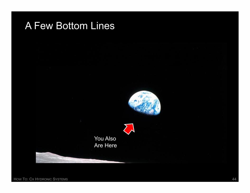
A Few Bottom Lines
You AlsoAre Here
HOW TO: CX HYDRONIC SYSTEMS 44

A Few Bottom Lines
Applying the principles we have been discussing can make a difference for as and for future generations
Applying the principles we have been discussing can be a lot of fun
HOW TO: CX HYDRONIC SYSTEMS 45

David SellersSenior Engineer
Facility Dynamics Engineeringwww.FacilityDynamics.comCell: 503-320-2630, Office: 503-286,1494Blog: www.Av8rDAS.Wordpress.com