how to increase the capacity efficiently in ammonia and ... · how to increase the capacity...
TRANSCRIPT
How to increase the Capacity Efficiently
in Ammonia and Urea Complexes:
THE UREA PLANT
by P. Bertini
UREA CASALE S.A. Lugano, Switzerland
For presentation at FAI INTERNATIONAL CONFERENCE ON FERTILISER TECHNOLOGY
New Delhi - India 21-22 April 2011
Via G. Pocobelli 6 6900 Lugano Switzerland Tel +41.91.960.72.00 Fax +41.91.960.72.91/2 www.casale.ch [email protected]
PDF created with pdfFactory trial version www.pdffactory.com
P. Bertini page 2
ABSTRACT Since the end of the 70's, the CASALE Group has gained a world-wide reputation for the revamping of existing ammonia and urea plants, and the Group is proudly a leader in this field of activity. CASALE's revamp strategy relies on an attitude and expertise to identify the bottlenecks in the ammonia and urea plants, and on the application of new, advanced technologies to obtain the best improvements in plant performance at the lowest cost. Especially in the last decade, AMMONIA and UREA CASALE have developed and successfully implemented several of these technologies, now consolidated concepts also for the design of new plants. Thanks to the strong interaction of the two sister companies, AMMONIA and UREA CASALE, the revamp of an ammonia-urea complex can be undertaken as a single, totally integrated design task since the conceptual stage and through the next project stages, a premium advantage that only the CASALE Group can boast, being the only company to license both Ammonia and Urea technologies. Especially for Indian fertilizer complexes, where typically all ammonia is converted to urea, there is a very strong link between the ammonia and the downstream urea plants: in this case CASALE is the best partner to implement a revamp that requires knowledge of the implications of selected revamp strategy on the whole fertilizer complex. This paper provides an overview of some of the CASALE technologies for urea plants, and some case histories of their application for revamping of existing plants.
PDF created with pdfFactory trial version www.pdffactory.com
P. Bertini page 3
FOREWORD AMMONIA CASALE S.A. is one of the oldest Companies active in the field of synthetic ammonia production. It has been established in Lugano (Switzerland) in 1921, for the industrial development and commercialization of Dr Luigi CASALE's inventions for the catalytic synthesis of ammonia. AMMONIA CASALE is well-known for its know-how, design and technologies in the field of ammonia plant design and revamping. More recently, the activities of CASALE have also expanded to the fields of urea (and methanol). Presently CASALE is a Group of companies active in various fields, with its main focus on the development of new technologies for the production of ammonia, urea and other products. CASALE's policy has long been based upon the development and application of advanced technologies for plant revamping, to get the best improvements in plant performance at the minimum cost. The improvements include energy consumption reduction, capacity increase, or a combination of both. The main strength of CASALE lies in the licensing of its technologies, developed in house by a team of very specialized people. Thanks to the innovative trend set by founder Dr Luigi CASALE, plus the heritage and background of subsequent management teams, CASALE invested significantly in technology development. During the last few decades this discipline evolved from an empirical art, with an intuitive sense for good design, into a more rationalized activity. Process design is now supported by sound insight into the chemistry of the processes, catalyst behaviors, kinetic data, heat and mass transfer phenomena, fluid mechanics, science of construction materials, and cost analysis. CASALE Technical Services avail themselves of specialists in all the above fields, as well as of sophisticated tools for investigating, analyzing and picturing complex phenomena in a way unachievable with ordinary skilled manual calculations. The process design is based on advanced computer-aided techniques with applications ranging from process flow-sheeting to kinetics, to fluid dynamics simulations and mechanical stress analysis. In addition to the technology, CASALE can also provide all services required for the completion of a project, from engineering right down to construction, start-up and operation of the plant. The typical Indian fertilizer complexes include two Self-Stripping Urea lines with a common prilling tower and a common section for the waste water treatment. The majority of these complexes have been revamped to increase the capacity and most of the margins available in the original design have been already reduced. In case of significant capacity increase, several bottlenecks can be individuated in the plant. A good revamping option makes possible to overcome these bottlenecks by the application of a simple and effective concept. In the following paragraphs of the paper a description of the technologies developed by CASALE to revamp all the sections of the Urea Plant for capacity increase up to 40-50% is given:
PDF created with pdfFactory trial version www.pdffactory.com
P. Bertini page 4
- CASALE technologies for the revamping of HP and decomposition Section:
• CASALE's Medium High Pressure (MHP) Section • CASALE's Split flow Loop and Full Condenser • CASALE's High Efficiency Trays • CASALE's Improved Loop Technology in the Hp Section
- CASALE technologies for the revamping of WWT Section:
• CASALE's High Efficiency Hydrolyser (HEH) - CASALE technologies for the revamping of the finishing section:
• Vortex Granulation Technology CASALE TECHNOLOGIES FOR THE REVAMPING OF HP AND DECOMPOSITION SECTION Most of the urea plants installed in India, based on Self Stripping technology, were originally designed with Titanium HP Stripper. Titanium material allows to keep very high temperature in the Stripper bottom (i.e. higher than 210°C), maximizing the carbamate decomposition at high pressure. On the other hand most of the HP Strippers are maintained with a bottom temperature of 203-204°C mainly because of two reasons: 1) many Titanium Strippers were replaced, because at the end of life, with Bimetallic strippers
which allowed 204°C as maximum bottom temperature. 2) a lower temperature in the stripper bottom allows an optimization of the steam consumption. In
fact, by reducing the stripper bottom temperature a higher quantity of carbamate is decomposed in the Medium Pressure Section where a lower quality steam is used.
The main consequences of the lower temperature in the HP Stripper bottom are the following: 1) higher load of the downstream sections, especially in the MP Section 2) lower load in the HP Carbamate condenser. In view of that, according to the analysis performed by CASALE during several feasibility studies of Indian Urea Plants revamping, a significant increase of the plant production (more than 40-50%) implies, in general, a huge intervention in all the parts of the Medium Pressure Section (i.e.
PDF created with pdfFactory trial version www.pdffactory.com

P. Bertini page 5
decomposition, condensation, NH3 absorption, NH3 condensation), as well as for the HP Pumps (i.e. HP Carbamate Pumps and HP NH3 Pumps). For these reasons, in case of significant increase of plant capacity, the revamping of the unit with a simple more in-more out approach cannot be economically justified. Moreover, considering also that in some cases several modifications have been already implemented on the existing plants, the number of new installations on the existing structure shall be minimized. CASALE identified two alternatives schemes/technologies to increase significantly (more than 40-50%) the capacity of urea plants installed in India, based on Self-Stripping technology: - CASALE's Medium High Pressure (MHP) Section technology
In case no intervention on HP Loop are necessary. - CASALE's Split flow Loop and Full Condenser technology
In case intervention on HP Loop are required. Furthermore CASALE propose, in combination with the above technologies, the implementation of the following technologies (if not already implemented): - CASALE's High Efficiency Trays - CASALE's Improved Loop Technology in the Hp Section CASALE'S MEDIUM HIGH PRESSURE (MHP) SECTION CASALE has individuated a solution for boosting the Medium Pressure section without affecting the performance in the synthesis, and even improving the reaction conditions. This solution is the implementation of a new Medium High Pressure Section (MHP), operating at a value intermediate between the HP and the MP operating conditions. In the new section, the urea solution stream from the stripper outlet would be further purified in the MHP Decomposer, before reaching the MP decomposer. Thanks to this intermediate decomposition, the quantity of vapors from the MP decomposer would be significantly lower with respect to the present conditions avoiding any modifications for MP Section (including the NH3 recovery section) as well as for the HP Carbamate Pumps and HP NH3 Pumps. Moreover, due to the lower quantity of unreacted CO2 and NH3 from the new MHP Section, the urea solution at MP Section outlet will result more purified thus reducing the load of the LP Section.
PDF created with pdfFactory trial version www.pdffactory.com
P. Bertini page 6
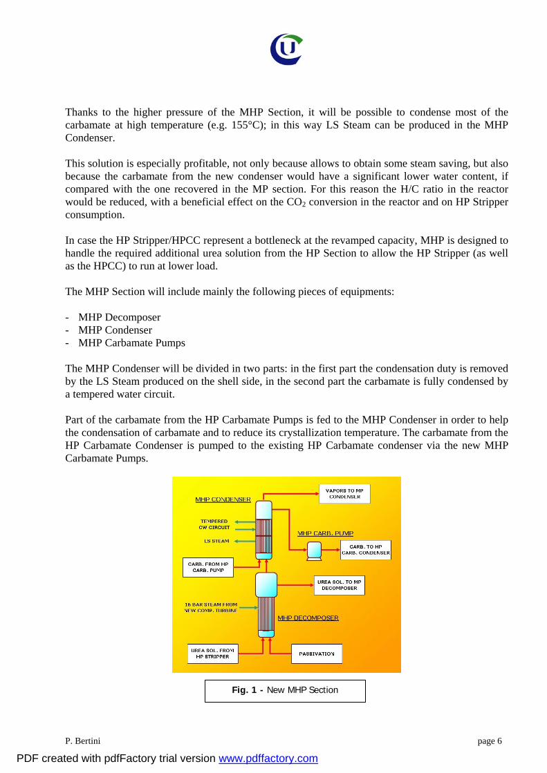
Thanks to the higher pressure of the MHP Section, it will be possible to condense most of the carbamate at high temperature (e.g. 155°C); in this way LS Steam can be produced in the MHP Condenser. This solution is especially profitable, not only because allows to obtain some steam saving, but also because the carbamate from the new condenser would have a significant lower water content, if compared with the one recovered in the MP section. For this reason the H/C ratio in the reactor would be reduced, with a beneficial effect on the CO2 conversion in the reactor and on HP Stripper consumption. In case the HP Stripper/HPCC represent a bottleneck at the revamped capacity, MHP is designed to handle the required additional urea solution from the HP Section to allow the HP Stripper (as well as the HPCC) to run at lower load. The MHP Section will include mainly the following pieces of equipments: - MHP Decomposer - MHP Condenser - MHP Carbamate Pumps The MHP Condenser will be divided in two parts: in the first part the condensation duty is removed by the LS Steam produced on the shell side, in the second part the carbamate is fully condensed by a tempered water circuit. Part of the carbamate from the HP Carbamate Pumps is fed to the MHP Condenser in order to help the condensation of carbamate and to reduce its crystallization temperature. The carbamate from the HP Carbamate Condenser is pumped to the existing HP Carbamate condenser via the new MHP Carbamate Pumps.
Fig. 1 - New MHP Section
PDF created with pdfFactory trial version www.pdffactory.com

P. Bertini page 7
CASALE'S SPLIT FLOW LOOP AND FULL CONDENSER TECHNOLOGY The CASALE Split Flow Loop is an improved CO2 stripping process. The main concept of the Split Flow Loop process is to split the total amount of inerts present in the CO2 feed so that only a minority portion is sent to the reactor, which is operating with the lowest possible amount of inerts. In addition, high condensation efficiency is reached in the HP carbamate condensation using a submerged condenser. This is achieved with the following steps: • The vapors, containing NH3, CO2, H2O and inerts, obtained from the HP stripper are split so that
a minority portion is sent directly to the reactor while the majority portion is sent to the HP carbamate condenser.
• The portion of vapor sent to the HP carbamate condenser is totally condensed, in a submerged condenser, obtaining a carbamate stream and an uncondensed stream of inerts.
• The stream of inerts leaving the HP carbamate condenser is sent straight to the HP scrubber, bypassing the reactor.
The main steps of the Split Flow Loop process are the following: • The solution from the reactor is first treated in a stripper, operating at the same pressure of the
reactor, where, using steam and CO2 as stripping agent, most of the unreacted NH3 and CO2 are recovered.
• Part of the unreacted NH3 and CO2 recovered in the stripper are sent directly to the reactor, while the rest is recycled back to the reactor through a HP condenser.
In this way, the synthesis section operates with very low inerts content with the following advantages: - high CO2 conversion in the reactor (up to 63-64%) - high stripping efficiency - high condensation efficiency. For this reason, the CASALE Split Flow Loop process is a process with high efficiency requiring, for a given capacity, equipment of smaller size with low investment costs. For what the operating costs are concerned, the Split Flow Loop process has values as low as the most advanced processes. The CASALE Split Flow Loop process is, therefore, suited for plants of very large capacity. The most critical equipment are, in fact, smaller, for a given capacity, than in conventional processes. The configuration of the HP loop of the Split Flow Loop process is shown in Fig. 2.
The solution leaving the reactor is treated in the HP stripper where the carbamate present in the solution and containing unreacted NH3 and CO2 is decomposed with the help of the CO2 feed as stripping agent.
PDF created with pdfFactory trial version www.pdffactory.com
P. Bertini page 8
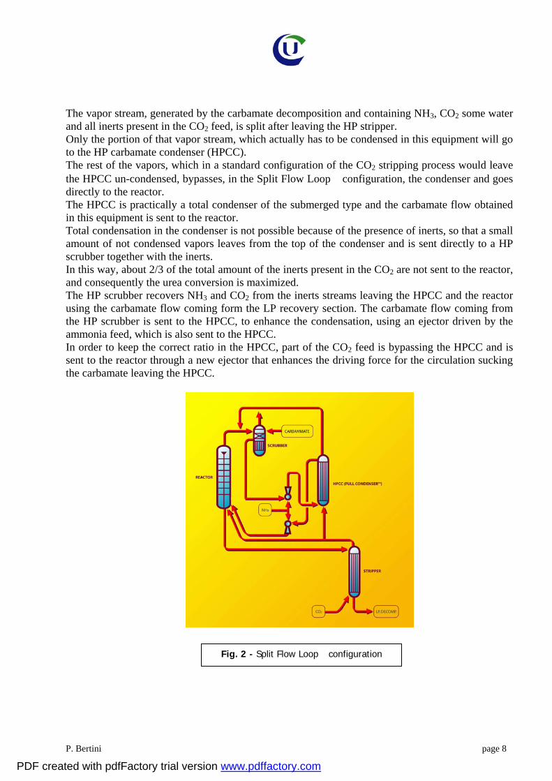
The vapor stream, generated by the carbamate decomposition and containing NH3, CO2 some water and all inerts present in the CO2 feed, is split after leaving the HP stripper. Only the portion of that vapor stream, which actually has to be condensed in this equipment will go to the HP carbamate condenser (HPCC). The rest of the vapors, which in a standard configuration of the CO2 stripping process would leave the HPCC un-condensed, bypasses, in the Split Flow Loop configuration, the condenser and goes directly to the reactor. The HPCC is practically a total condenser of the submerged type and the carbamate flow obtained in this equipment is sent to the reactor. Total condensation in the condenser is not possible because of the presence of inerts, so that a small amount of not condensed vapors leaves from the top of the condenser and is sent directly to a HP scrubber together with the inerts. In this way, about 2/3 of the total amount of the inerts present in the CO2 are not sent to the reactor, and consequently the urea conversion is maximized. The HP scrubber recovers NH3 and CO2 from the inerts streams leaving the HPCC and the reactor using the carbamate flow coming form the LP recovery section. The carbamate flow coming from the HP scrubber is sent to the HPCC, to enhance the condensation, using an ejector driven by the ammonia feed, which is also sent to the HPCC. In order to keep the correct ratio in the HPCC, part of the CO2 feed is bypassing the HPCC and is sent to the reactor through a new ejector that enhances the driving force for the circulation sucking the carbamate leaving the HPCC.
Fig. 2 - Split Flow Loop configuration
PDF created with pdfFactory trial version www.pdffactory.com
P. Bertini page 9
CASALE Split Flow Loop process – characterizing elements
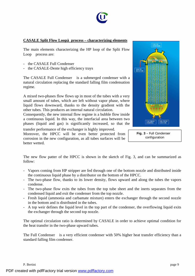
The main elements characterizing the HP loop of the Split Flow Loop process are: - the CASALE Full Condenser - the CASALE-Dente high efficiency trays
The CASALE Full Condenser is a submerged condenser with a natural circulation replacing the standard falling film condensation regime.
A mixed two-phases flow flows up in most of the tubes with a very small amount of tubes, which are left without vapor phase, where liquid flows downward, thanks to the density gradient with the other tubes. This produces an internal natural circulation. Consequently, the new internal flow regime is a bubble flow inside a continuous liquid. In this way, the interfacial area between two phases (liquid and gas) is significantly increased, so that the transfer performance of the exchanger is highly improved. Moreover, the HPCC will be even better protected from corrosion in the new configuration, as all tubes surfaces will be better wetted.
The new flow patter of the HPCC is shown in the sketch of Fig. 3, and can be summarized as follow: - Vapors coming from HP stripper are fed through one of the bottom nozzle and distributed inside
the continuous liquid phase by a distributor on the bottom of the HPCC. - The two-phase flow, thanks to its lower density, flows upward and along the tubes the vapors
condense. - The two-phase flow exits the tubes from the top tube sheet and the inerts separates from the
condensed liquid and exit the condenser from the top nozzle. - Fresh liquid (ammonia and carbamate mixture) enters the exchanger through the second nozzle
in the bottom and is distributed in the tubes. - A top weir defines the liquid level in the top part of the condenser, the overflowing liquid exits
the exchanger through the second top nozzle.
The optimal circulation ratio is determined by CASALE in order to achieve optimal condition for the heat transfer in the two-phase upward tubes.
The Full Condenser is a very efficient condenser with 50% higher heat transfer efficiency than a standard falling film condenser.
Fig. 3 - Full Condenser configuration
PDF created with pdfFactory trial version www.pdffactory.com

P. Bertini page 10
In addition being a submerged condenser a significant amount of urea is formed in the condenser itself reducing the load of the reactor. All the above features are obtained with a very simple, proven and reliable mechanical design used in many applications for the falling film configuration. With a very simple improvement in the internal part, the same design can work in a much more efficient configuration. CASALE Split Flow Loop for large increase of capacity in Self-Stripping Urea Units In case the implementation of MHP Section technology does not prevent the installation of new pieces of HP equipment (e.g. HP Reactor), CASALE propose the installation of the advanced Split Flow Loop technology (jointly with Full Condenser technology) in parallel to the existing Synthesis/MP Section. Thanks to the installation of this new very efficient HP Loop, no modifications will be required in the existing HP Section and MP Section. The new Synthesis is fed by a new CO2 compressor driven by Steam turbine provided with steam extraction for the MS steam required by the new HP Stripper and with reinjection of the excess of LS Steam produced by the new HPCC (not used into the process). Thanks to the high efficiency of CO2 stripping, the Urea solution from the HP Stripper can be directly fed to the existing LP Section.
NNeeww SSpplliitt
FFllooww LLoooopp
UUrreeaa SSoolluuttiioonn
MMPP SSeeccttiioonn UUrreeaa ssooll..
CCaarrbboonnaattee
PPIICC
AAddddiittiioonnaall WWaatteerr
LLPP SSeeccttiioonn WWWWTT
RReeccyyccllee
NN 77%% wwtt.. CC 88%% wwtt.. UU 5588%% wwtt.. HH 2277%% wwtt..
NN 77%% wwtt.. CC 11..55%% wwtt.. UU 6622%% wwtt.. HH 2299..55%% wwtt..
Fig. 4 - New Split Flow LoopTM Revamp
PDF created with pdfFactory trial version www.pdffactory.com

P. Bertini page 11
Considering that the urea solution from the HP Stripper contains a very low quantity of NH3 vs. CO2 also the resultant carbonate in the existing LP section will contain less quantity of NH3. For example, in typical Self-Stripping Urea Plant the N/C ratio is abt. 9-13; for this reason a large amount of water is required to be added to avoid excessive NH3 losses from the LP Section vents: H/C ratio is typically 7-10. In case a new HP Loop is installed to increase the plant capacity of 40%, the N/C ratio in the LP Section decreases down to 4-5. Therefore the required amount of Water to be added in the LP Section decreases drastically: with an H/C ratio of 5 it is possible to assure zero NH3 losses from the LP vent. Further energy saving is possible by recovering the condensation duty of the HP Scrubber in the new Evaporation Section which needs to be installed to concentrate the additional urea solution from the LP Section. Fig. 5 shows a simplified scheme of the energy recovery: the tempered water from the HP Scrubber is fed to the lower bundle of the vacuum evaporator, in this way it is possible to save abt. 120 kg of LS Steam/MT of Urea required in the evaporation section.
CASALE-DENTE HIGH EFFICIENCY TRAYS
Fig. 5 - Simplified Scheme of Energy Recovery
PDF created with pdfFactory trial version www.pdffactory.com

P. Bertini page 12
Fig. 6 - CASALE-Dente High Efficiency Trays
The development of this technology was the first example, in CASALE activity in the urea field, of how the investigation and analysis of complex phenomena, and the ability to picture it through the combination of process design and fluid dynamics tools, could lead to the development of most advanced technologies. In collaboration with Professor Dente, UREA CASALE was able, through an accurate modeling, to identify all the parameters that are influencing the formation of urea inside a urea reactor. Through the modeling it became clear that a good transfer of mass and heat within the phases of the heterogeneous reacting system of urea is of essence to reach a high conversion in the reactor. With the models, its was also possible to identify that the existing designs of internals (trays) used in urea reactors could be improved.
The CASALE-Dente High Efficiency Trays design improves the tray geometry realizing a higher mixing with a much better mixing between the liquid and vapor phases. The new trays are, in fact, designed so that: • Separate and distributed paths through the tray are provided. They guarantee a steady state flow
of the two phases and better approach an even uniform flow of the two phases throughout the whole reactor.
• These separated paths through the tray are chosen so that a very high mixing efficiency between vapor and liquid is obtained. Consequently a very high mass and heat transport within the liquid phase is realized.
• With an appropriate design, the diameter of the generated vapor bubbles is smaller than in any previous design. By consequence, the interfacial surface, for mass and heat transfer, is increased.
• A much higher mixing within the liquid phase is also obtained. The trays are made up by several inverted U beams with large perforations for liquid passage on the bottom wings, and small perforations for gas passage on the sloping and top sections.
PDF created with pdfFactory trial version www.pdffactory.com
P. Bertini page 13
With this unique design, very small bubbles are generated, and by consequence, very high specific surface for the mass and heat transfer is obtained. This advantage is combined with a very high efficiency in the mixing between vapors and liquid. The CASALE-Dente High Efficiency Trays are used for any project aiming at reducing the steam consumption and/or at increasing the plant capacity. So far the CASALE-Dente High Efficiency Trays are operating in more than 50 urea plants. CASALE'S IMPROVED LOOP TECHNOLOGY IN THE HP SECTION
In combination with the two previous technologies (MHP Section & Split Flow–Full Condenser), CASALE propose a minor modification to the HP loop piping to prevent the necessity of feeding passivation air (from a dedicated compressor) at the stripper bottom; of course this technology is not applied for Titanium HP Stripper. Through this modification all the passivation air fed along with CO2 will be conveyed at the bottom of the stripper, thus guarantying a much better passivation effect compared to the present situation. The above described scheme is already implemented since November 2008 in a plant in Russia where the stripper bottom has been inspected after 13 months operations and found in excellent condition. Through the application of CASALE Patented Improved Loop Technology the following improvements can be achieved: 1. The possibility to put out of operation the passivation air compressor used at stripper bottom,
with the saving on the operational costs;
2. The minimization of the inert content in the HP Loop, so enhancing the condensation in HPCC, insuring the protection of the material without any additional risk with respect to the present conditions;
3. The decrease of the overall amount of inerts fed to the ammonia recovery system, resulting in a
lowering of ammonia vented from MP washing column almost proportional.
PDF created with pdfFactory trial version www.pdffactory.com
P. Bertini page 14
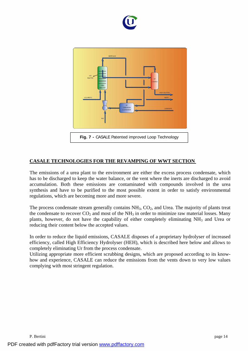
Fig. 7 - CASALE Patented improved Loop Technology
CASALE TECHNOLOGIES FOR THE REVAMPING OF WWT SECTION The emissions of a urea plant to the environment are either the excess process condensate, which has to be discharged to keep the water balance, or the vent where the inerts are discharged to avoid accumulation. Both these emissions are contaminated with compounds involved in the urea synthesis and have to be purified to the most possible extent in order to satisfy environmental regulations, which are becoming more and more severe. The process condensate stream generally contains NH3, CO2, and Urea. The majority of plants treat the condensate to recover CO2 and most of the NH3 in order to minimize raw material losses. Many plants, however, do not have the capability of either completely eliminating NH3 and Urea or reducing their content below the accepted values. In order to reduce the liquid emissions, CASALE disposes of a proprietary hydrolyser of increased efficiency, called High Efficiency Hydrolyser (HEH), which is described here below and allows to completely eliminating Ur from the process condensate. Utilizing appropriate more efficient scrubbing designs, which are proposed according to its know-how and experience, CASALE can reduce the emissions from the vents down to very low values complying with most stringent regulation.
PDF created with pdfFactory trial version www.pdffactory.com
P. Bertini page 15
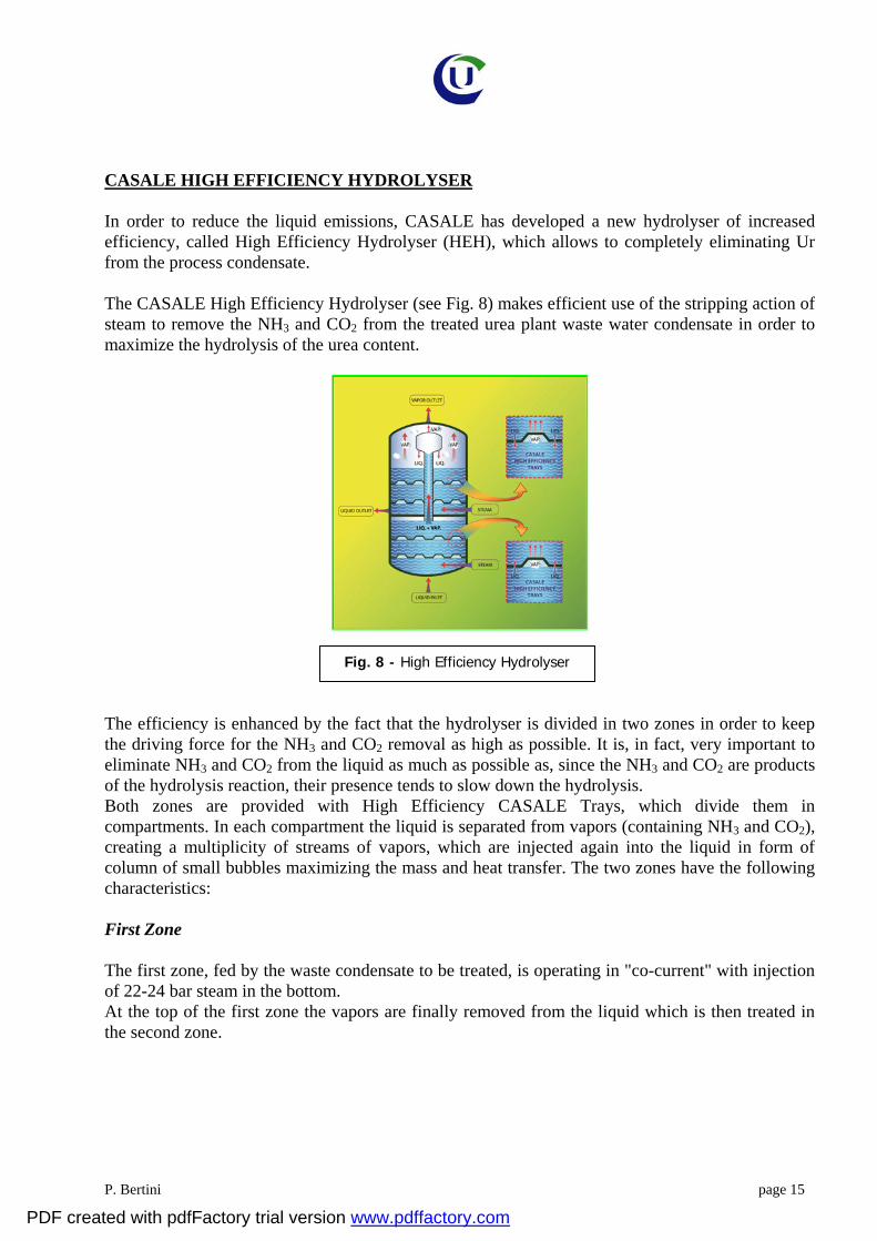
Fig. 8 - High Efficiency Hydrolyser
CASALE HIGH EFFICIENCY HYDROLYSER In order to reduce the liquid emissions, CASALE has developed a new hydrolyser of increased efficiency, called High Efficiency Hydrolyser (HEH), which allows to completely eliminating Ur from the process condensate. The CASALE High Efficiency Hydrolyser (see Fig. 8) makes efficient use of the stripping action of steam to remove the NH3 and CO2 from the treated urea plant waste water condensate in order to maximize the hydrolysis of the urea content.
The efficiency is enhanced by the fact that the hydrolyser is divided in two zones in order to keep the driving force for the NH3 and CO2 removal as high as possible. It is, in fact, very important to eliminate NH3 and CO2 from the liquid as much as possible as, since the NH3 and CO2 are products of the hydrolysis reaction, their presence tends to slow down the hydrolysis. Both zones are provided with High Efficiency CASALE Trays, which divide them in compartments. In each compartment the liquid is separated from vapors (containing NH3 and CO2), creating a multiplicity of streams of vapors, which are injected again into the liquid in form of column of small bubbles maximizing the mass and heat transfer. The two zones have the following characteristics: First Zone The first zone, fed by the waste condensate to be treated, is operating in "co-current" with injection of 22-24 bar steam in the bottom. At the top of the first zone the vapors are finally removed from the liquid which is then treated in the second zone.
PDF created with pdfFactory trial version www.pdffactory.com
P. Bertini page 16
Second Zone The second zone, fed by the liquid coming from the first zone, operates in "counter-current" with liquid going downward and vapor going upward. Fresh 22-24 bar steam is injected again in the bottom of this second zone. The driving force for the extraction of NH3 and CO2 is, in this way, increased, allowing to reduce urea content to less than 3 ppm. The vapors are separated from the liquid at the top of the zone and exit the hydrolyser together with the vapors coming from the first zone. With the help of CASALE High Efficiency Hydrolyser, adding, if necessary, one or two stripping columns, it is possible to completely eliminate NH3 and Urea from the process condensate reaching residual values lower than 3 ppm. This value meets the requirements for boiler feed water; the treated condensate can, therefore, be used as boiler feed with economical advantages. The CASALE High Efficiency Hydrolyser is used when it is necessary to reduce the emission of Urea and NH3 through the process condensate, or to increase the capacity of existing hydrolyser. Existing hydrolysers of certain types can be also conveniently revamped by changing the internals with new ones designed according to the High Efficiency Hydrolyser technology. So far the CASALE High Efficiency Hydrolysers are operating in more than 15 urea plants. VORTEX GRANULATION TECHNOLOGY The Vortex Granulation developed by UREA CASALE is an innovative granulation technology based on the fluid bed technology. The Vortex Granulation combines the advantages of the fluid bed granulation technology with the ones of the drum granulation. The features of the Vortex Granulation are the following: - low energy consumption - minimum use of formaldehyde - high product quality - low investment - high flexibility in the production - wide range of application including prilling tower revamping This technology can also be conveniently used to debottleneck existing prilling towers for capacity enhancing and quality improvement.
PDF created with pdfFactory trial version www.pdffactory.com

P. Bertini page 17
Fig. 1 – Rotating fluid bed
Technical Description The two main characterizing elements of the Vortex granulation technology are: - the Vortex granulator - the Spraying nozzles Vortex Granulator The Vortex granulator, which is the core of the Vortex granulation technology, is a rotating fluid bed.
In this rotating fluid bed the particles are fluidized with air fed from the bottom through a grid but, differently to any other fluid bed used for granulation, the fluidized particles have two types of motion:
- The longitudinal motion typical of all fluid beds used for granulation. - A circular motion that generates two eddies (Vortex) characteristic of the Vortex rotating fluid
bed. This principle is shown in figure 1.
The rotating motion of the particles obtained in the Vortex granulator is somewhat similar to the motion obtained in drum granulators and allows to have a better control of the spraying of melt on the particle particles in the bed.
Urea melt (L) is, in fact, sprayed into the rotating fluid bed from the side, as shown in the figure 2, and not from the bottom as in state of the art technologies.
PDF created with pdfFactory trial version www.pdffactory.com

P. Bertini page 18
Fig. 2 – Vortex Granulator
In this way the wetting and solidification processes of the growing particles follows a cycle that is very regular and controlled. The cycle is repeated many times while the particles are following the circular paths of the vortex and consists of two steps;
- Wetting of the particles with new melt as they reach the position of the lateral spraying nozzles; - Solidification and cooling of the newly deposited melt as they follow the rest of the path. The growing granules are moving along the length of the Vortex granulator with a plug flow motion, from one end, where the seeds (S) are introduced, to the opposite end where the product (P) is taken out. During this longitudinal motion, the growing particles undergo many of the cycles mentioned above so that the seed are slowly enlarged and reaches the final desired size.
As the melt is sprayed very uniformly all along the length of the granulator, a uniform growth of the granule is achieved and the final product has a size distribution equal or better than the seeds.
Spraying nozzles Melt urea is sprayed into the fluid bed using innovative nozzles developed by CASALE.
The main function of the nozzle in the granulation process is to produce small droplets, or a thin film, of urea melt in order to deposit the right amount of melt on the growing granules.
PDF created with pdfFactory trial version www.pdffactory.com

P. Bertini page 19
Fig. 3 – Spraying Nozzle
As CASALE has chosen to operate the Vortex granulator with 96% urea solution, it is important that the nozzle will generate very small droplets in order to guarantee the proper evaporation of the 4% water contained in the solution.
The innovative concept of the nozzle is that the very small droplets are generated through the formation of an emulsion of air in urea, which is then sprayed out of the nozzle.
As shown in figure 3, in the nozzle air is injected into the jet of melt generating a multitude of small bubbles (emulsion). The air present in the emulsion breaks the emulsion jet exiting the nozzle into the very small liquid droplets that are required to obtain a perfect granulation.
The advantage of this concept is that the amount of air required for the nozzles to generate the very small bubbles is very low with a significant saving of compression energy.
The Vortex granulation unit Thanks to the fact that the growth of the seeds entering the Vortex granulator is very uniform and constant, it is possible to design granulation units, based on the Vortex granulator, which are very simple.
In particular it is possible to eliminate the screening, crushing and recycle of the oversized and undersized exiting the granulator.
In the Vortex granulation plant a seeding unit is generating the seeds for the granulator. The seeds are generated with a very uniform distribution and the product exiting the granulator is already on-spec.
PDF created with pdfFactory trial version www.pdffactory.com
P. Bertini page 20
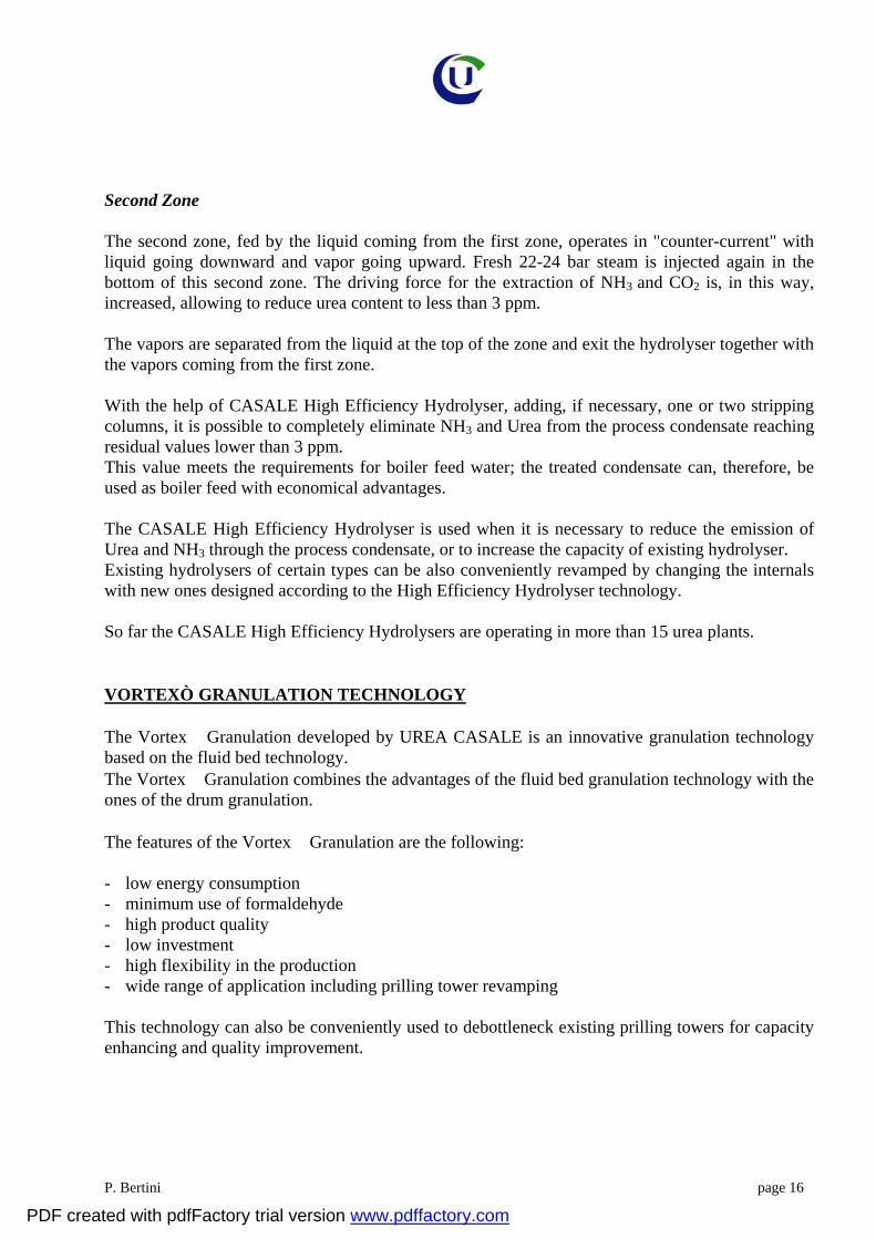
Fig. 4 – Vortex Granulation
Air is blown into the bottom of the granulator to fluidize the particle and to generate the rotation. Air is also blown into the nozzle to generate the above-mentioned emulsion and around the nozzles to protect the jets of droplets.
The air exiting the granulator is sent to a scrubbing unit to eliminate the dust and, if required, also ammonia. Proper care is given to the selection of the scrubbing design in order to guarantee the elimination of urea down to the allowable levels. The product exiting the granulator is sent to a solid cooler for the final cooling. The Vortex granulation plant has, therefore, a once-through configuration becoming very simple, as shown in figure 4. One other important feature of the Vortex granulation technology is that the Vortex granulator is designed to be modular as the size of the eddies is standardized. In this way, units of different capacity can be designed just by varying the length of the granulator and the number of the eddies.
It is, therefore, possible to design large granulation plants with minimal scale-up risks.
The plant becomes also very compact as shown in the 3D model shown in figure 6. APPLICATION OF VORTEX GRANULATION TECHNOLOGY TO PLANT
PDF created with pdfFactory trial version www.pdffactory.com
P. Bertini page 21
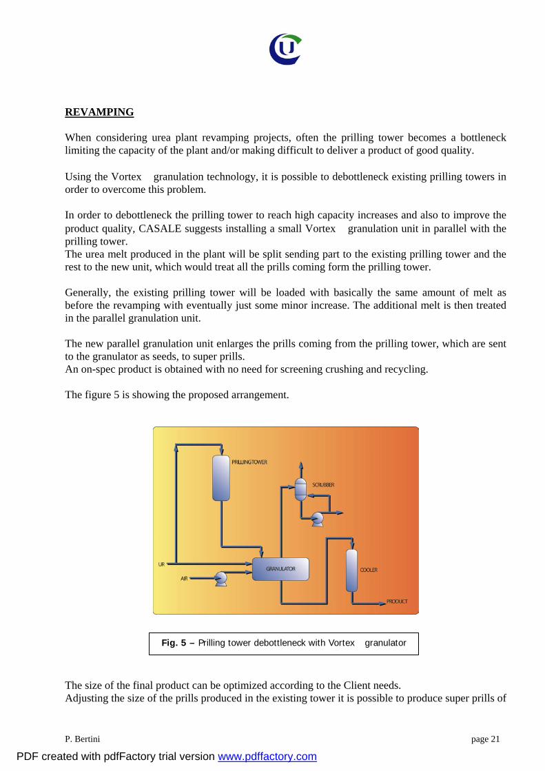
Fig. 5 – Prilling tower debottleneck with Vortex granulator
REVAMPING When considering urea plant revamping projects, often the prilling tower becomes a bottleneck limiting the capacity of the plant and/or making difficult to deliver a product of good quality.
Using the Vortex granulation technology, it is possible to debottleneck existing prilling towers in order to overcome this problem.
In order to debottleneck the prilling tower to reach high capacity increases and also to improve the product quality, CASALE suggests installing a small Vortex granulation unit in parallel with the prilling tower. The urea melt produced in the plant will be split sending part to the existing prilling tower and the rest to the new unit, which would treat all the prills coming form the prilling tower.
Generally, the existing prilling tower will be loaded with basically the same amount of melt as before the revamping with eventually just some minor increase. The additional melt is then treated in the parallel granulation unit.
The new parallel granulation unit enlarges the prills coming from the prilling tower, which are sent to the granulator as seeds, to super prills. An on-spec product is obtained with no need for screening crushing and recycling.
The figure 5 is showing the proposed arrangement.
The size of the final product can be optimized according to the Client needs. Adjusting the size of the prills produced in the existing tower it is possible to produce super prills of
PDF created with pdfFactory trial version www.pdffactory.com
P. Bertini page 22
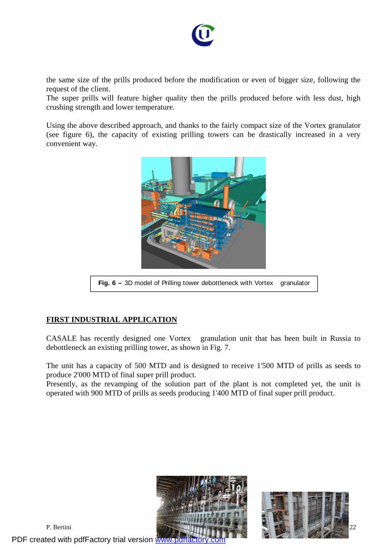
Fig. 6 – 3D model of Prilling tower debottleneck with Vortex granulator
the same size of the prills produced before the modification or even of bigger size, following the request of the client. The super prills will feature higher quality then the prills produced before with less dust, high crushing strength and lower temperature. Using the above described approach, and thanks to the fairly compact size of the Vortex granulator (see figure 6), the capacity of existing prilling towers can be drastically increased in a very convenient way.
FIRST INDUSTRIAL APPLICATION CASALE has recently designed one Vortex granulation unit that has been built in Russia to debottleneck an existing prilling tower, as shown in Fig. 7. The unit has a capacity of 500 MTD and is designed to receive 1'500 MTD of prills as seeds to produce 2'000 MTD of final super prill product. Presently, as the revamping of the solution part of the plant is not completed yet, the unit is operated with 900 MTD of prills as seeds producing 1'400 MTD of final super prill product.
PDF created with pdfFactory trial version www.pdffactory.com
P. Bertini page 23
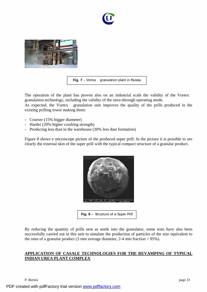
Fig. 7 - Vortex granulation plant in Russia
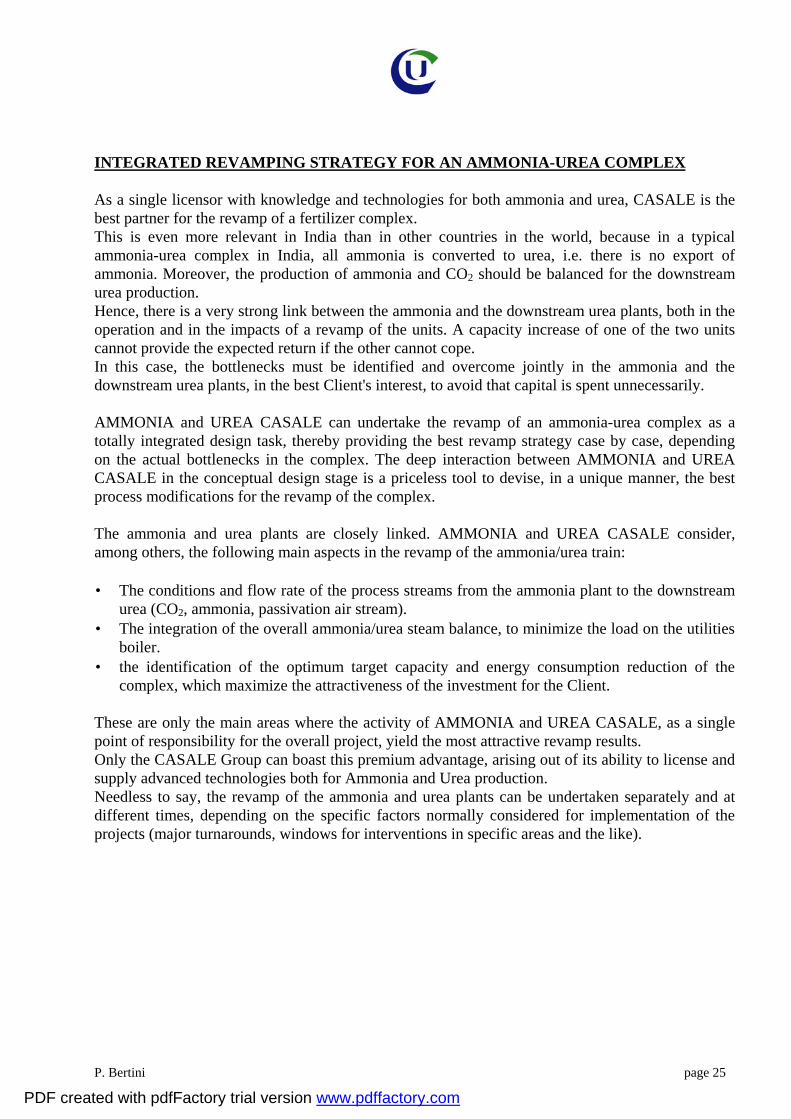
Fig. 8 – Structure of a Super Prill
The operation of the plant has proven also on an industrial scale the validity of the Vortex granulation technology, including the validity of the once-through operating mode. As expected, the Vortex granulation unit improves the quality of the prills produced in the existing prilling tower making them: - Courser (15% bigger diameter) - Harder (20% higher crushing strength) - Producing less dust in the warehouse (30% less dust formation) Figure 8 shows e microscope picture of the produced super prill. In the picture it is possible to see clearly the external skin of the super prill with the typical compact structure of a granular product.
By reducing the quantity of prills sent as seeds into the granulator, some tests have also been successfully carried out in this unit to simulate the production of particles of the size equivalent to the ones of a granular product (3 mm average diameter, 2-4 mm fraction > 95%). APPLICATION OF CASALE TECHNOLOGIES FOR THE REVAMPING OF TYPICAL INDIAN UREA PLANT COMPLEX
PDF created with pdfFactory trial version www.pdffactory.com

P. Bertini page 24
Fig. 9 – CASALE Technologies for Revamping of TYPICAL INDIAN UREA PLANT
Considering the typical layout of Indian fertilizer complexes, which include two Self-Stripping Urea lines with a common prilling tower and a common section for the waste water treatment, the revamping scheme can be further optimized in to reduce the investment cost and the energy consumption. In case the MHP Section technology is applicable to debottleneck the HP Section and the Decomposition Section, a common Section will be implemented for both lines. The Urea Solution from both lines is fed to the common MHP Section; the decomposed solution is split to the MP Sections which do not need any modifications. In several Indian plants the original HP Stripper has been replaced with new one; the old equipment could be reused as MHP Decomposer, at very less critical conditions. Regarding the finishing section a new common evaporation section is foreseen to concentrate the urea solution at 96% wt. to be feed to the new Vortex Granulator. A new parallel Vortex Granulator is installed to enlarge the prills coming from the prilling tower, which are sent to the granulator as seeds, to super prills. An on-spec product is obtained with no need for screening crushing and recycling.
PDF created with pdfFactory trial version www.pdffactory.com
P. Bertini page 25
INTEGRATED REVAMPING STRATEGY FOR AN AMMONIA-UREA COMPLEX
As a single licensor with knowledge and technologies for both ammonia and urea, CASALE is the best partner for the revamp of a fertilizer complex. This is even more relevant in India than in other countries in the world, because in a typical ammonia-urea complex in India, all ammonia is converted to urea, i.e. there is no export of ammonia. Moreover, the production of ammonia and CO2 should be balanced for the downstream urea production. Hence, there is a very strong link between the ammonia and the downstream urea plants, both in the operation and in the impacts of a revamp of the units. A capacity increase of one of the two units cannot provide the expected return if the other cannot cope. In this case, the bottlenecks must be identified and overcome jointly in the ammonia and the downstream urea plants, in the best Client's interest, to avoid that capital is spent unnecessarily. AMMONIA and UREA CASALE can undertake the revamp of an ammonia-urea complex as a totally integrated design task, thereby providing the best revamp strategy case by case, depending on the actual bottlenecks in the complex. The deep interaction between AMMONIA and UREA CASALE in the conceptual design stage is a priceless tool to devise, in a unique manner, the best process modifications for the revamp of the complex. The ammonia and urea plants are closely linked. AMMONIA and UREA CASALE consider, among others, the following main aspects in the revamp of the ammonia/urea train: • The conditions and flow rate of the process streams from the ammonia plant to the downstream
urea (CO2, ammonia, passivation air stream). • The integration of the overall ammonia/urea steam balance, to minimize the load on the utilities
boiler. • the identification of the optimum target capacity and energy consumption reduction of the
complex, which maximize the attractiveness of the investment for the Client.
These are only the main areas where the activity of AMMONIA and UREA CASALE, as a single point of responsibility for the overall project, yield the most attractive revamp results. Only the CASALE Group can boast this premium advantage, arising out of its ability to license and supply advanced technologies both for Ammonia and Urea production. Needless to say, the revamp of the ammonia and urea plants can be undertaken separately and at different times, depending on the specific factors normally considered for implementation of the projects (major turnarounds, windows for interventions in specific areas and the like).
PDF created with pdfFactory trial version www.pdffactory.com

P. Bertini page 26
CONCLUSIONS
The cases described here above are only examples of the different and possible schemes of the modifications that can be applied to any ammonia plant to improve the performances thereof. Moreover, development of new technologies is always ongoing at CASALE, to further improve the existing plants capacity, consumption, reliability and operation. The CASALE approach is to customize the revamping to the real needs of the plant, by taking into proper consideration the major bottlenecks in the ammonia and urea plants, which can be overcome cost-effectively. Thanks to its unique position as the licensor of technologies for ammonia and urea, CASALE is the best partner to implement a revamp of an ammonia/urea train, which requires knowledge of the implications of selected strategy on the whole fertilizer complex.
PDF created with pdfFactory trial version www.pdffactory.com