how to monitor aux channel communication of displayport
TRANSCRIPT

How to Monitor AUX Channel Communicationof DisplayPort Interfaces

DisplayPort Interface
Main Link: Serialized / encoded video, audio and external data
AUX Channel: Command data > < Status data
HPD: Hot Plug Detect signal
PHY Layer
Link Layer
Application Layer
PHY Layer
Link Layer
Application Layer
DP Source Device DP Sink Device

AUX Channel Topology
DP Source Device
• Single differential pair.
• Half-duplex bidirectional operation.
• 1 Mbps using Manchester-II coding.
• Master of the AUX Channel
(called AUX CH Requester).
• Must initiate a
Request Transaction.
• AUX Channel slave
(AUX CH Replier).
• Responds with a
Reply Transaction.
AUX Channel
DP Sink Device

Use of AUX Channel
• Link Capability Read
• Link Configuration (training)
• Link Status Read
AUX Link Services
• EDID Read
• MCCS (Monitor Command and Control Set) support
• Sink Event Notification
AUX Device Services
• Send & Receive Messages from Remote DP Nodes
• Report MST Status Changes and Errors
Sideband Messaging

AUX Channel Protocol Example 1
Source Sink
Req RD 1 byte from 0x00218 90 02 19 00 AUX ACK (1 byte) 00 00
Source: Read one byte of data from DPCD 0x00218
Sink: OK,
TEST_REQUEST (Test requested by the Sink device):
0x00218 := 0x00
TEST_LINK_TRAINING = 0
TEST_VIDEO_PATTERN = 0
TEST_EDID_READ = 0
PHY_TEST_PATTERN = 0
FAUX_TEST_PATTERN = 0
Read from Sink DPCD
Please refer to: DP v1.2a: 2.9.3.1 Address Mapping for Link Configuration/Management

AUX Channel Protocol Example 2
Source Sink
Req WR 5 bytes to 0x00102 80 01 02 04 22 38 38 38 38 ACK 00
Source: Write 5 bytes of data to DPCD 0x00102
TRAINING_PATTERN_SET (0x00102 := 0x22)
TRAINING_PATTERN_SET = 2 (Pattern 2)
RECOVERED_CLOCK_OUT_EN = 0
SCRAMBLING_DISABLE = 1
SYMBOL_ERROR_COUNT_SEL = 0 (Disparity and Illegal Symbol)
TRAINING_LANE0_SET (Link Training Control, Lane 0)(0x00103 := 0x38)
VOLTAGE_SWING_SET = level 0
MAX_SWING_REACHED = 0
PRE_EMPHASIS_SET = level 3
MAX_PRE-EMPHASIS_REACHED = 1 etc. …
Sink: OK
Write to Sink DPCD
Please refer to: DP v1.2a 2.9.3.1 Address Mapping for Link Configuration/Management

AUX Channel Protocol Example 3
DOWN_REQ - REQ: LINK_ADDRESS
-- Sideband message header --
Link_Count_Total = 1
Link_Count_Remaining = 0
Broadcast_Message = 0
Path_Message = 0
MSG_Body_Length = 2
Start_Of_MT = 1
End_Of_MT = 1
Message_Sequence_No = 0
Sideband Message - step 1 (Request)
Source Sink
Req WR 5 bytes to 0x01000 80 10 00 04 10 02 cb 01 d5 ACK 00
Please refer to: DP v1.2a 2.9.3.1 Address Mapping for Link Configuration/Management

AUX Channel Protocol Example 3
DEVICE_SERVICE_IRQ_VECTOR_ESI0 [CLR] [1.2]
0x02003 := 0x10
(Reserved) REMOTE_CONTOL_COMMAND_PENDING = 0
AUTOMATED_TEST_REQUEST = 0
CP_IRQ = 0
MCCS_IRQ = 0
DOWN_REP_MSG_RDY = 1
UP_REQ_MSG_RDY = 0
SINK_SPECIFIC_IRQ = 0
Sideband Message - step 2 (Enquire Reply)
Source Sink
Req RD 1 bytes from 0x02003 90 20 03 00 AUX_ACK - 1 bytes 00 10
Please refer to: DP v1.2a 2.9.3.1 Address Mapping for Link Configuration/Management
AUX Channel Protocol Example 3
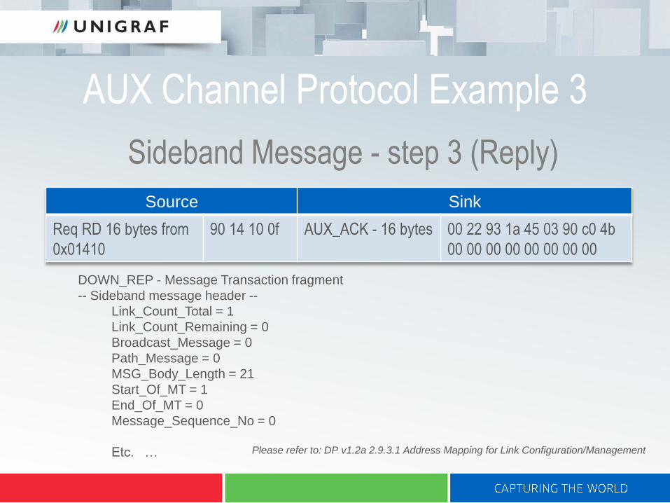
DOWN_REP - Message Transaction fragment
-- Sideband message header --
Link_Count_Total = 1
Link_Count_Remaining = 0
Broadcast_Message = 0
Path_Message = 0
MSG_Body_Length = 21
Start_Of_MT = 1
End_Of_MT = 0
Message_Sequence_No = 0
Etc. …
Sideband Message - step 3 (Reply)
Source Sink
Req RD 16 bytes from
0x01410
90 14 10 0f AUX_ACK - 16 bytes 00 22 93 1a 45 03 90 c0 4b
00 00 00 00 00 00 00 00
Please refer to: DP v1.2a 2.9.3.1 Address Mapping for Link Configuration/Management

AUX Monitor
Equipment:
• DPA-400 1.2 unit
• Unigraf “Y” cable
• AUX Channel Monitor GUI
USB
Any DP SinkAny DP Source
Host PC
AUX
Monitor
GUI

DPR-120 Embedded AUX Monitor
Equipment:
• DPR-120 unit
• Debug and Test Controller GUI
• MST Debug Extension optionUSB
DP Reference Sink
DP Source
Host PC
Debug and Test
Controller GUI
Embedded
AUX Monitor
Tab

Unigraf AUX Monitor GUI
Parsed interpretation of one transactionAUX Channel
transaction log
Log controls

Case: Interoperability Testing
DP Source DP Sink
D.U.T.
AUX
Monitor
GUI

Case: Interoperability Testing
DP Source
DP Sink
AUX
Monitor
GUI
D.U.T.

Case: Link Compliance Testing
DP Source
DP Reference Sink
Embedded
AUX Monitor Tab
Compliance Testing Tab
D.U.T.
Both tools in
DPR-120
Debug and Test
Controller GUI

Case: MST Interoperability Testing
DP Source
DP Reference Branch
DP Sink
D.U.T.
Embedded
AUX
Monitor
Tab
Stream
Allocation
Monitor
Tab
Both tools in DPR-120
Debug and Test Controller GUI

Case: MST Interoperability Testing
DP Source
DP Branch
DP Sink
Stream
Allocation
Monitor
Tab
D.U.T.
DP Reference
Branch
AUX
Monitor
GUI

Case: MST Interoperability Testing
DP Source
DP Branch
DP Sink
Stream
Allocation
Monitor
Tab
DP Reference
Branch
AUX
Monitor
GUI
D.U.T.

DisplayPort MST Interoperability Test Procedure
DP Source
D.U.T.
“Monitor” 1
Monitor 2 Monitor 3 Monitor 4
Cable 1
“Cab
le”
2
“Cable” 3 “Cable” 4
Embedded
AUX
Monitor
Tab
AUX
Monitor
GUI
Please refer to: VESA DisplayPort® Multi-Stream Transport Certification Test Procedure; Revision D

DisplayPort MST Interoperability Test Procedure
DP Source
D.U.T.
“Monitor” 1
“Monitor” 2 “Monitor” 3 “Monitor” 4
Cable 1
Cab
le 2
Cable 3 Cable 4
Embedded
AUX
Monitor
Tab
Please refer to: VESA DisplayPort® Multi-Stream Transport Certification Test Procedure; Revision D
Stream
Allocation
Monitor
Tab
All tools in
DPR-120
Debug and
Test Controller
GUI

Summary
• DPA-400 Advantages:
Can be used between any Source and Sink
Needed between MST Branch and Sink
• DPR-120 Built-in AUX Advantages:
Link CTS tool and AUX Monitor in the same GUI
Reduces the # of connectors in the stream path
