how to order one final note - hydramaster …€¦ · i how to order one final note: ... all parts...
TRANSCRIPT


I HOW TO ORDER ONE FINAL NOTE:To obtain a proper diagnosis of your malfunction, and to order Any questions you have regarding the warranty program should be
warranty replacement parts, it is important that you proceed in the directed to the Warranty Service Dept. Personnel at HydraMaster
following manner: Corporation.
I 1. Call HydraMaster Warranty/Service Dept. at (206) 775-7275, We shall always endeavor to be fair in our evaluation of your
2. Give the Warranty/Service Representative the followingwarranty claim, and shall prowde you with a complete analysis of
information:our findings,
A. Name of your company and your address,B. Equipment Model (i.e. CDS).C. Date of purchase.D. Hours on the unit.E. Serial number of unit.F. Name of person authorized to order parts.
G. Salesman unit purchased from.H. Description of malfunction.1, Pressure readings on high pressure gauge with wand turned
on and off.
3. If warranty replacement parts are needed, please specifymethod of shipment desired. NOTE: All replacement parts aresent freight collect, via:
A. U.P.S.B. Air freightC. Air mailD, Air expressE. Auto Freight
4. Do not give malfunctioning parts to a HydraMaster Sales orService Representative. All parts must be returned directlyto HydraMaster, freight prepaid.
HydraMaster Warranty PolicyEffective April 1, 1987
HydraMaster warranty covers only defective materials and/orworkmanship for the periods Iwted. Labor. and/or diagnosticreimbursement is specifically excluded.
HOURS:MONDAY THROUGH FRIDAY
7:00 am TO 6:00 pmPACIFIC STANDARD TIME
@@@@
PST ROCK MT. CENTRAL EASTERN
TELEPHONE NUMBERSGENERAL OFFICES: (206) 775-7272PARTS DEPI (206) 775-7276SERVICE/WARRANTY (206) 775-7275NEW EQUIPMENT SALES
AND MARKETING: 1-800-426.1301
Table of ContentsParts Order . . . . . . . . . . . . . . . . . . . . . . . . . . . . . . . . . . . . . . . . . . . . . . 2
Water Flow Diagram . . . . . . . . . . . . . . . . . . . . . . . . . . . . . . . . . . . . . . 2Water and Chemical Flow Operation . . . . . . . . . . . . . . . . . . . . . . . 3Water Softener . . . . . . . . . . . . . . . . . . . . . . . . . . . . . . . . . . . . . . . . . . . 3Water Softener Hook-up Diagram . . . . . . . . . . . . . . . . . . . 4Jet Assembly . . . . . . . . . . . . . . . . . . . . . . . . . . . . . . . . . . . . . . . . . . . . 4Wand Assembly . . . . . . . . . . . . . . . . . . . . . . . . . . . . . . . . . . . . . . . . . . 4Valve Assembly . . . . . . . . . . . . . . . . . . . . . . . . . . . . . . . . . . . . . . . . . . 5Stem Assembly . . . . . . . . . . . . . . . . . . . . . . . . . . . . . . . . . . . . . . . . . . 5Vacuum System Information . . . . . . . . . . . . . . . . . . . . . . . . . . . . . . . 6Vacuum Flow Diagram, . . . . . . . . . . . . . . . . . . . . . . . . . . . . . . . . . . . 6Vacuum Tank Filter Bags . . . . . . . . . . . . . . . . . . . . . . . . . . . . . . ...7Blower Lubricant . . . . . . . . . . . . . . . . . . . . . . . . . . . . . . . . . . . . . . . . . 7Vacuum Blower Warranty . . . . . . . . . . . . . . . . . . . . . . . . . . . 8Factory Authorized Service
Centers for Sutorbilt Products . . . . . . . . . . . . . . . . . . . . . . . . . . . 9Lubrication (Vacuum Blower Motor) . . . . . . . . . . . . . . . . . . . . . ...10Filling Procedure (Vacuum Blower Motor) . . . . . . . . . . . . . . . . ...10Vacuum Blower Troubleshooting Guide . . . . . . . . . . . . . . . . . ...11Cat Pump Model 290, Operating
Instructions &Specifications . . . . . . . . . . . . . . . . . . . . . . . . . ...13Cat Pump Warranty . . . . . . . . . . . . . . . . . . . . . . . . . . . . . . . . . . . ...14General information for Cat Pump Repair . . . . . . . . . . . . . . . . ...15Bypass Valve illustration . . . . . . . . . . . . . . . . . . . . . . . . . . . . . . . ...15Chemical Proportioning and
Level Control illustration . . . . . . . . . . . . . . . . . . . . . . . . . . . . . ...16Chemical Tank Trouble Shooting . . . . . . . . . . . . . . . . . . . . . . . ...16Pump-in System Flow Diagram . . . . . . . . . . . . . . . . . . . . . . . . . ...18Cat PumpDimensions. . . . . . . . . . . . . . . . . . . . . . . . . . . . . . . . . ...18
Important Drive Information . . . . . . . . . . . . . . . . . . . . . . . . . . . . ...19
Specifications (pump) . . . . . . . . . . . . . . . . . . . . . . . . . . . . . . . . . ...19Piston Mode1290 Exploded View,.. . . . . . . . . . . . . . . . . . . . . ...20Parts List Mode1290 . . . . . . . . . . . . . . . . . . . . . . . . . . . . . . . . . . . ...20
mmmmuflbw[iwmlr,,,l tlllsllJllllllMll.,lu,llnm,,n'l!hlln'll,,tll,'lbll~l,,tm,,,,lm,,,,,,l,,,,t',l,,,,,,l!,lll,,,lM
Service Kits Mode1290 . . . . . . . . . . . . . . . . . . . . . . . . . . . . . . . . ...22Servicing the Valve Assemblies . . . . . . . . . . . . . . . . . . . . . . . . . ...23Servicing the Pumping Section .,, . . . . . . . . . . . . . . . . . . . . . . ...24Servicing Sleeves and Seals . . . . . . . . . . . . . . . . . . . . . . . . . . . ...25Servicing Crankcase Section . . . . . . . . . . . . . . . . . . . . . . . . . . . ...26Cat Pump Trouble Shooting Guide.. . . . . . . . . . . . . . . . . . . . . ...27Electrical System . . . . . . . . . . . . . . . . . . . . . . . . . . . . . . . . . . . . . . ...31Electrical Diagram . . . . . . . . . . . . . . . . . . . . . . . . . . . . . . . . . . . . . ...32Freeze Protection . . . . . . . . . . . . . . . . . . . . . . . . . . . . . . . . . . . . . ...33Cleaning and Chemical Precautions Information. . . . . . . . . . ...33Cleaning Stroke Procedure/Over-Wetting. . . . . . . . . . . . . . . . ...34Maintenance Procedure . . . . . . . . . . . . . . . . . . . . . . . . . . . . . . . . ...35Overall Careof Unit . . . . . . . . . . . . . . . . . . . . . . . . . . . . . . . . . . . ...35Freeze Protection of Clutch Drive with Pump-In System . . . ...36Maintenance Log . . . . . . . . . . . . . . . . . . . . . . . . . . . . . . . . . . ...36.39Warranty Information . . . . . . . . . . . . . . . . . . . . . . . . . . . . . . . . . . ...40Warranty Procedure . . . . . . . . . . . . . . . . . . . . . . . . . . . . . . . . . . . ...40HydraMaster Limited Warranty. .Inside back cover
Machine Serial No.Q 1987 HydraMaster Corp.
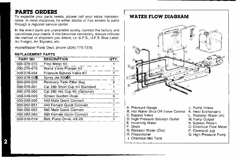
PARTS ORDERSTo expedite your parts needs, please call your sales represen-tative. In most instances, he either stocks or has access to parts
through a regional service center.
In the event parts are unavailable locally, contact the factory andcoordinate your needs. If this becomes necessary, always indicatethe method of shipment you desire, i.e. U. P.S., U.P.S. Blue Label,Air Freight, Air Express, etc.
HydraMaster Parts Dept. phone (206) 775-7276.
REPLACEMENT PARTS
PART NO. DESCRIPTlON QTY.
000-078-015 Flow Meter Kit 1
000-078-019 Wand Valve Plunaer Kit 1
000-078-034 Pressure Bypass Valve Kit 1
000-076-00s Spray Jet 80r2$E 1
000-049-028 Recovery Tank Filter Bag 2
000-078-001 Cat 290 Short Cup Kit Standard 1
000-078-004 Cat 290 Hot Cup Kit (Optional) 1
000-049-023 Screen Garden Hose 6
000-052-050 440 Male Quick Connect 1
000-052-051 440 Female Quick Connect 1
000-052-052 660 Male Quick Connect 1
000-052-053 660 Female Quick Connect 1
000-0” 0-019 Belt, Pump Drive. AX-26 1
WATER FLOW DIAGRAM
A. Pressure GaugeB. Hot Water Shut-Off Valve ControlC. Bypass ValveD, High Pressure Solution OutletE. incoming WaterF. Drain
G. Radiator Water (Out)H. Proportioner1. Chemical Mix Tank
J.K.L.M.
Pump IntakeHeat ExchangersRadiator Water (In)Pump Output
N. Bypass R&turnO. Chemical Flow MeterP. Chemical Jug
Q. High Pressure Pun’Ip

WATER AND CHEMICAL FLOWOPERATIONThis system has been designed to be the most simple and trouble-free ever.
The incoming water flows directly to the mix tank. Water will nowflow through a proportioning valve which will simultaneously mixthe chemical to achieve your desired solution. The mix tank isequipped with 2 different float valves, one of which responds to thewater level of the tank and will maintain the proper volume of solu-tion to be reserved for the cat pump. The secondary float valve is asafety valve that is designed to protect your system from sudden orunexpected loss of water supply. If, for example, the water source
at the house was turned off, the water level of the mix tankwould drop, activating the secondary valve which automatically
disengages the electric pump clutch.
In conjunction with the incoming flow, the chemical ratio may beobtained by an adjustment of the chemical flow meter during the fillcycle of the mix tank. The chemical will flow from the chemical jugto the chemical flow meter, then to the proportioner where it isdistributed into the mix tank at your desired proportion. This lineshould be flushed with vinegar weekly to prevent abnormalchemical build-up, This may be done by removing the clear plastichose from the chemical jug and inserting it into a one quart con-tainer of vinegar. This should be done with the chemical flow metersetting on 10 GPH with heater “off”. Simply spray the wand for theduration of the vinegar in the one quart container, then repeat theprocess with clear water to void all lines of vinegar.
NOTE: With this unique chemical system, your chemical flow isproportioned to the filling cycles of the mix tank, not the directspraying of the wand. Therefore, it is possible that as your wand isspraying, you may have no chemical flow, Also, the converse istrue in that you may not be spraying your wand but, if the mix tank
is in a filling cycle your chemical flow meter may read your desiredflow.
This chemical system will mix a 1 to 30 ratio when flow meter is setat 5 GPH, Most chemical suppliers will recommend a 1 to 15 ratiotherefore you can either set the flow meter at 10 GPH, giving you a1 to 15 ratio of chemical to cleaning water, or double the recom-mended strength of chemical in the 5 gallon jug and set the flowmeter at 5 GPH, thereby attaining a 1 to 15 ratio. (It is recom-mended that you set the flow meter at 10 GPH for overall bestresults.)
The water will now be siphoned from the bottom of the mix tank tothe Cat Pump. If the wand is not spraying, the water will bypassfrom the bottom of the brass pressure relief valve to the mix tank.
WATER SOFTENERMany areas of the country have an excess of minerals in the waterwhich results in what is commonly called “hard water”, Theseminerals tend to adhere to the insides of heater coils and otherparts of the machines causing damage and a loss of cleaningeffectiveness.
Reports from several of our machine users commending theresults of the use of water softeners in conjunction with theirmachines prompts us to recommend the procedure to everyone ina “hard water” area.
The relatively low cost of a water softener service is more than
made up for in the increased life of machine parts and continuedcleaning efficiency. The water softener will also increase the effec-tiveness of the cleaning chemical being used, therefore, lesschemical will be needed,
!contmea next page)
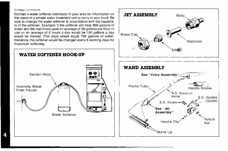
(Softener, continued) IContact a water softener distributor in your area for information onthe rental of a simple water treatment unit to carry in your truck. Besure to change the water softener in accordance with the capabili-ty of the softener. Example: If the softener will treat 900 gallons ofwater and the machines uses an average of 30 gallons per hour ofuse on an average of 5 hours a day would be 150 gallons a daywould be treated. Five days would equal 750 gallons of water,
therefore, the softener would be changed every 6 working days formaximum softening.
WATER SOFTENER HOOK-UP
Garden Hose
m
oo~
\
.mme.Cw
Incoming WaterFrom Faucet
J Jw
w@o00
@
Water Softener
JET ASSEMBLY Body\
@
,...
Brass CapP
,&’@<80~S~’bzer
WAND ASSEMBLY————
See “Valve Assembly” ~-- -\+: . .
.X=‘v=
~ram, ‘rube\ ,,,/”~ .~:::Handle Sleeve
d
,/’S.S. Solut[onl-lose
/“’ S.S. Handle
@
, (Guide)
‘“’” \~,:’sJ;crew-%’ “.
\ Assembly”
\
s. @
‘“M 7‘“Y
Handle ClipNylockNut
+&\\Wand Lip
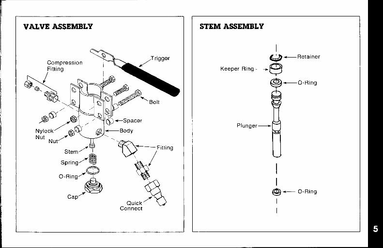
VALVE ASSEMBLY
Nylock. . . .. ‘J@~ @j\-Body
O-Ring=-A
Quick’ wConnect
STEM ASSEMBLY
I
w +----Retainer
Keeper Ring—~
9_O-Ring
l!!
Plunger+
@+ O-Ring
I
—

VACUUM SYSTEM INFORMATIONThe vacuum blower incorporated in this machine is a positive
displacement lobe type, manufactured by Fuller Company. Theperformance and life of this unit is greatly dependent on the careand proper maintenance it receives.
Because of the close tolerances between the lobes and housing ofthe vacuum blower, solid objects entering the inlet will damage theinternal lobes, gears and bearing or direct drive coupler.
To prevent this, a stainless steel filter screen has been placed atthe vacuum inlet inside the vacuum recovery tank. This stainlesssteel screen is finger tight and should be removed weekly forcleaning.
Caution should be used when machine is being run for test pur-pose and the vacuum inlet on top of machine is open.
To protect the vacuum blower from overloading and damaging
itself, there is a vacuum relief system installed on the vac tank.
When the vacuum tank inlet is completely sealed off, a maximumof 12 HG will be attained. A blower lube port is located above thevacuum gauge; at the end of each day, LPS 1 or WD-40 is sprayedin before shutting down the machine. See blower lubricationillustration. If you fail to lubricate the vacuum blower daily, rust
deposits and moisture will decrease the life of the vacuum blower.
Caution: Foam passing through the blower could lead to seriousproblems, therefore, it is important to keep the vacuum tank foamfree.
VACUUM FLOW DIAGRAM
Filter Bag/
Recovery Tank
CleaningWand w
Vacuum Blower
\Blower
ExhaustSilencer
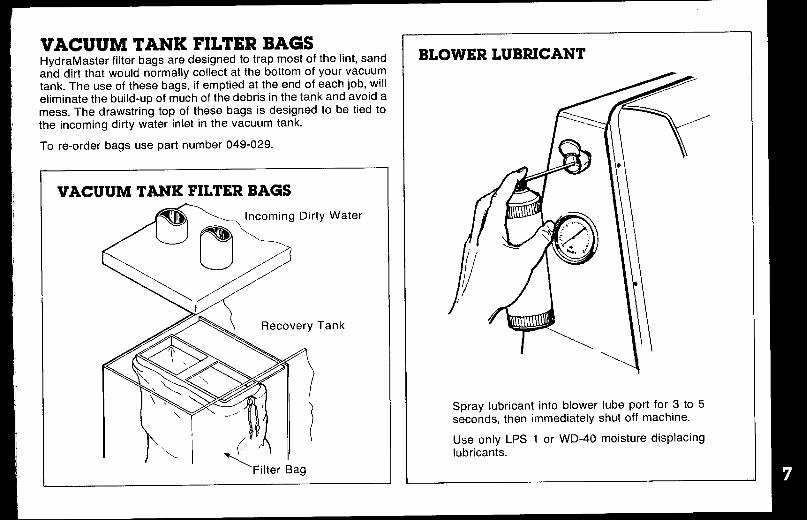
VACUUM TANK FILTER BAGSHydraMaSter filter bags are designed to trap most of the lint, sandand dirt that would normally collect at the bottom of your vacuumtank. The use of these bags, if emptied at the end of each job, willeliminate the build-up of much of the debris in the tank and avoid amess. The drawstring top of these bags is designed to be tied tothe incoming dirty water inlet in the vacuum tank.
To re-order bags use part number 049-029.
VACUUM TANK FILTER BAGS
ty Water
Tank
‘Filter Bag
BLOWER LUBRICANT
Spray lubricant into blower lube port for 3 to 5seconds, then immediately shut off machine.
Use onlv LPS 1 or WD-40 moisture displacin9lubrican~s.

VACUUM BLOWER WARRANTYFULLER warrants products of its manufacture to be free fromdefects In material and workmanship if properly installed, main-tained, and operated under normal conditions with competentsuperwwon,
No person, agent, representative or dealer is authorized to giveany warranties on behalf of FULLER nor to assume for FULLERany other habllity in connection with any of FULLER’S products.
This warranty shall extend for one (1) year from date of installa-tion provided this equipment has been put into serwce withinSIX months after shipment from the FULLER factory. If repairsor replacements are made by the Purchaser wrthout FULLER’Sprior written consent, FULLER’S warranty shall cease to be ineffect. No allowance will be granted for any repairs or altera-tions made by the Purchaser without FULLER’S prior writtenconsent.
Machinery, equipment and accessories furnished by FULLER,but manufactured by others, are warranted only to the extent ofthe original manufacturer’s warranty to FULLER.
FULLER agrees at its option to repair at the point of shipment orto replace without charge f.o.b. point of shipment, any part orparts of products of FULLER’S manufacture, which within thespecified warranty period shall be proved to FULLER’Ssatisfaction to have been defective when shipped, prowded thePurchaser promptly notifies FULLER, in writing, of such allegeddefect.
FULLER’S Ilabllity to Purchaser, whether in contract or [n tortarising out of warranties. representations. instructions. ordefects from any cause shall be Iimlted to repalrlng or replaclngof the defectwe part or parts as aforesaid, f.o. b. point ofshipment.
No Ilabllity whatsoever shall attach to FULLER until said pro-ducts have been paid for.
EXCEPT AS STATED IN THIS SECTION AND IN THEPRECEDING SECTION TITLED ‘WARRANTY’” AND EXCEPTAS TO TITLE, THERE ARE NO GUARANTEES OR WARRAN-TIES OF MERCHANTABILITY, FITNESS, PERFORMANCEOR OTHERWISE, EXPRESS, IMPLIED OR STATUTORY,AND FULLER SHALL HAVE NO LIABILITY FOR CONSE-QUENTIAL, INCIDENTAL OR OTHER DAMAGES,HOWSOEVER CAUSED.
Date Installed
Model
Serial #
FULLER COMPANY2966 East V[ctoria StreetCompton, California 90224

},
FACTORY AUTHORIZED SERVICE CENTERS FOR SUTORBILT PRODUCTS rFULLER COMPANY / COMPTON DIVISION GREGORY-SALISBURY & CO.2966 E. Victoria St., Compton, CA 90224 805 South Front Street213/636-9821 or 639-7600 New Orleans, Lousiana 70130
504/524-5207FULLER COMPANY / MANHElM DIVISION236 South Cherry Street SCHWARZ FOUNDRY COMPANYManheim, Pennsylvania 17545 2001 West Fort Street71 7/665-2224 Detroit, Michigan 48216
313/496-1880BAYLISS MACHINE & WELDING CO.2901 8th Avenue North CAROTEK INCORPORATED
Birmingham, Alabama 35203 640 Sam Newell Road205/323-6121 Mathews, N. Carolina 28105
704/847-4406BARNEY’S PUMPS INC.3907 Highway 98 South DYNMAC CORPORATION
Lakeland, Florida 33802 7925 E. 40th Street
81 3/686-8195 Tulsa, Oklahoma 74145918/627-0110
ASSOCIATED TECHNICAL SERVICE, INC.
1229 Waimanu Street #21Honolulu, Hawaii 96814
[
8081537 -’I 206
WM. W. MEYER & SONS
8261 Elmwood Avenue
ELECTRIC CRAFTS LTD.3936 Edmonton Trail NE.Calgary, Alberta T2E 3P6403/276-9676
PUMPS & POWER LTD.1380 Napier StreetVancouver, B. C., Canada
604/255-4341
GATX-FULLER LTD.721 Progress AvenueScarborough, Ontario, Canada4 16/438-6540
FULLER CO MI=A
I
a —.—Ail A GATX COMPANY I
u 2966 East Victoria Street I
Post Office Box 4308, Compton, California 90224
Tel: (21 3) 639-7600 (213) 636-9821 Telex: 67-4607
Skokie, Illinois 6007631 2/673-0312
OLIVER & LAUGHTER EQUIPMENT CO.10450 WestofficeHouston, Texas 77042713/977-2577

LMBIUCATIONAt the gear end the timing gear teeth are lubricated by beingpartially submerged. The gear teeth serve as oil slingers forgear end bearings. At the drive end the bearings are greaselubricated.
FILLING PROCEDURERemove square head vented oil fill plug (A) on gear end.Remove oil level plug (B) located in the head plate. Fill gear
case until oil drips out of the oil level hole (B).
Use lubricants as listed.
Add fresh oil as required to maintain proper level. The oil
should be drained, flushed and replaced every 1500 hours ormore frequently (f inspection so indicates. The oil drain plug isat (C).
NOTE: Older units may have the oil fill level and drain holes
located in the cast iron gear case instead of in the head plate.
Bearings on drive end of blower require grease lubricationevery 100 hours of operation. Bearings which require greaselubrication will have a grease fitting (D) at each bearing. Whenregressing, the old grease will be forced out of the vents during
operation. To prevent damage to seals, these vents must bekept open at all times.

VACUUM BLOWER TROUBLE SHOOTING GUIDEPROBLEM: Loss of Vacuum
Cause Solution
Collapsed vacuum hose between blower and vacuum tank. Remove and replace hose. NOTE: A special reinforced hoseis reauired for replacement.
Clogged stainless steel filter. Remove and, clean or replace stainless steel filter.
Defective vacuum tank seal. Remove and re~lace vacuum tank seal,
Defective or ‘open’ vacuum tank dump valve. Close valve.
Re~lace valve.
Fractured weld on vacuum tank. Re-weld as required or replace tank.
Colla~sed or kinked vacuum hose. flesha~e hose if Dossible and/or eliminate kinks.
Plugged vacuum hose, Remove obstruction by reversing the vacuum hose.
Restriction in cleaning tool. Remove obstruction,
Worn end plates or lobes in vacuum blower. Replace worn components. NOTE: Must be accomplished bya aualified technician.
Loose drive shaft between clutch and blower, The set screws may come loose causing blower to stand stillwhile engine may be turning properly. NOTE: Unless theblower is seized or making a knocking noise, your vacuumloss is not caused by a bad blower.
PROBLEM: Blower is Seized
Cause Solution
Rust. Spray rust dissolving lubricant onto lobes to emulsify rust andattempt to rotate vacuum lobes.
Foreign matter. Disassemble and remove foreign matter and repair asrequired. NOTE: Disassembly must be accomplished byaualified technician.
NOTE: The above mentioned, rust, foreign matter and seizing are often caused from foam traveling through the blower.
fconl!nued next page)
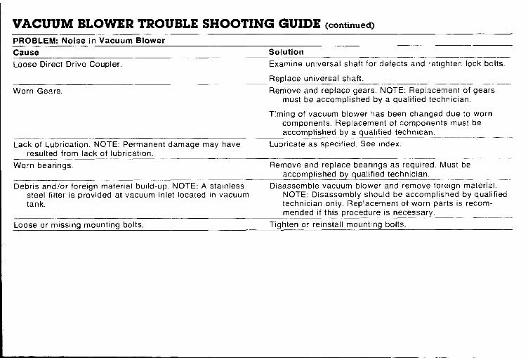
VACUUM BLOWER TROUBLE SHOOTING GUIDE (continued]
PROBLEM: Noise in Vacuum Blower
Cause Solution
Loose Direct Drive Coupler. Examine universal shaft for defects and retighten lock bolts.
Replace universal shaft.
Worn Gears. Remove and replace gears. NOTE: Replacement of gearsmust be accomplished by a qualified technician.
Timing of vacuum blower has been changed due to worncomponents. Replacement of components must beaccomplished by a qualified technican.
Lack of Lubrication. NOTE: Permanent damage may have Lubricate as specified. See index.
resulted from lack of lubrication.
Worn bearings, Remove and replace bearings as required. Must beaccomplished bv aualified technician.
Debris and/or foreign material build-up. NOTE: A stainless Disassemble vacuum blower and remove foreign material.
steel filter is provided at vacuum inlet located in vacuum NOTE: Disassembly should be accomplished by qualified
tank. technician only, Replacement of worn parts is recom-mended if this procedure is necessary.
Loose or missing mounting bolts.
—...—.Tighten or reinstall mounting bolts.

CAT PUMPS Model 290
OPERATING INSTRUCTIONSCAUTION: CAT PUMPS are positive displacement pumps,Therefore, a properly designed pressure relief mechanism MUSTbe installed in the discharge piping, Failure to install such reliefmechanism could result in personal injury or damage to the pumpor system. Cat Pumps Corporation does not assume any liability orresponsibility for the operation of a customer’s high pressuresystem,
SPECIFICATIONSVolume: 3,5 GPM (13 L/M)Discharge Pressure: 1200 PSI (83 BAR)Maximum Inlet Pressure: -8.5 to + 40 PSI (-0.6 to + 2.8 BAR)RPM: 1200 RPM (1200 RPM)Bore: 0.787” (20 mm)Stroke 0.472;’ (12 mm)Crankcase Capacity: 10 oz. (,3 L)Maximum Fluid Temperature 160”F (71 ‘C)Inlet Ports (1): 1/2” NPT (1/2” NPT)
Chemical Injection Port (l): 1/4” NPT (1/4” NPT)Discharge Ports (2): 3/8” NPT (3/6” NPT)
(l): 1/2” NPT (1/2” NPT)Pulley Mounting: Either side (Either side)Shaft Diameter: 0.650” (16.5 mm)Weight: 12.1 Ibs. (5.5 kg)Dimensions: 10.77’’x9.06’’x5 .14” (273,5 x230x130.5 mm)
Products described hereon are covered by one or more ofthe following U.S. patents: 3558244, 3652188, 3809508,3920356, and 3930756
-, ● CAT PUMPS — AG ●
LOrOtOhoehe 5
J~’Map~-TCH-6300 ZUG Switzerland
Phone (42) 21-3140 – Ts(m 865160 ccmg ch
CORPORATION● CAT PUMPS OEUTSCHLANO Gmbw ●
Rostocke, StraSSC, 9P O Box S85 MINNEAPOLIS, MN 55440 6200 Wlesbaden.B!erst.9dt West GermanyPhone (612) 780-5440 – Telex 294276 Phone 0612.56000712 — Telex 41 86713
● N V CAT PUMPS INTERNATIONAL SA ● ● CAT PUMPS (U K , LTD ●
Harrno”,estraal 29 27 Stalkon Indu.str,al Estate, FleetB 20Q0 Antwerp, Belg,um Hampshire GU13 8QY, Engla.d
Phone (03) 237.72.24 — Telex 33947 Phone Fleet 22031 — Telex 856898
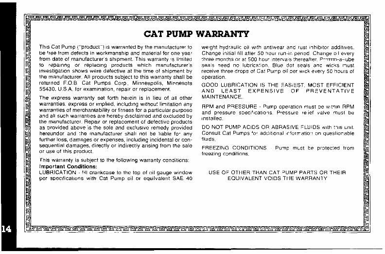
CAT PUMPThis Cat Pump (“product”) is warranted by the manufacturer tobe free from defects in workmanship and material for one yearfrom date of manufacturer’s shipment. This warranty is limitedto repairing or replacing products which manufacturer’sinvestigation shows were defective at the time of shipment bythe manufacturer. All products subject to this warranty shall bereturned F.O. B. Cat Pumps Corp., Minneapolis, Minnesota55430. U.S.A. for exammation, repair or replacement.
The express warranty set forth herein is in lieu of all otherwarranties, express or implied, including without limitation anywarranties of merchantability or fitness for a particular purposeand all such warranties are hereby dtsclalmed and excluded bythe manufacturer. Repair or replacement of defective productsas provided above is the sole and exclusive remedy providedhereunder and the manufacturer shall not be liable for anyfurther loss, damages or expenses, including incidental or con-sequential damages, directly or indirectly arising from the saleor use of this product.
This warranty is subject to the following warranty conditions:
Important Conditions:LUBRICATION - fill crankcase to the top of oil gauge windowper specifications with Cat Pump oil or equivalent SAE 40
WARRANTYweight hydraulic oil with antlwear and rust lnhibltor addltwes.Change initial fill after 50 hour run-in period, Change 011everythree months or at 500 hour Intervals thereafter. Prrrrrm-a-lubeseals need no lubrication. Blue dot seals and wicks mustrecewe three drops of Cat Pump 011per wick every 50 hours ofoperation.
GOOD LUBRICATION IS THE EASIEST, MOST EFFICIENTAND LEAST EXPENSIVE OF PREVENTATIVEMAINTENANCE,
F(PM and PRESSURE - Pump operation must be wlthln RPMand pressure specifications. Pressure relief valve must be[nstalled,
DO NOT PUMP ACIDS OR ABRASIVE FLUIDS with this unit.Consult Cat Pumps for addlt!onal information on questionablefluids.
FREEZING CONDITIONS - Pump must be protected fromfreezing conditions.
USE OF OTHER THAN CAT PUMP PARTS OREQUIVALENT VOIDS THE WARRANTY
THEIR
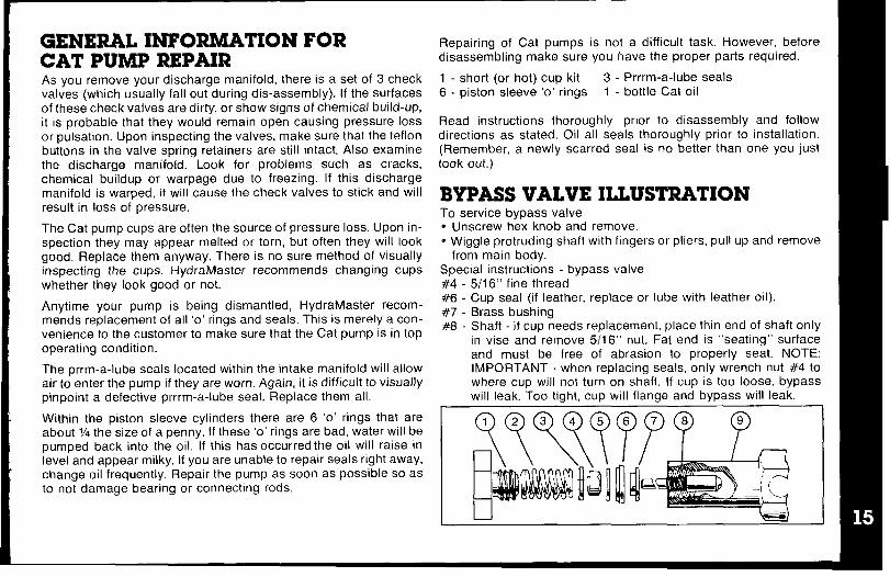
GENERAL INFORMATION FORCAT PUMP REPAIRAs you remove your discharge manifold, there is a set of 3 checkvalves (which usually fall out during dis-assembly). If the surfacesof these check valves are dirty, or show signs of chemical build-up,it is probable that they would remain open causing pressure lossor pulsation. Upon inspecting the valves, make sure that the teflonbuttons in the valve spring retainers are still intact. Also examinethe discharge manifold. Look for problems such as cracks,chemical buildup or warpage due to freezing. If this dischargemanifold is warped, it will cause the check valves to stick and willresult in loss of pressure.
The Cat pump cups are often the source of pressure loss. Upon in-spection they may appear melted or torn, but often they will lookgood, Replace them anyway. There is no sure method of visuallyinspecting the cups. HydraMaster recommends changing cupswhether they look good or not.
Anytime your pump is being dismantled, HydraMaster recom-mends replacement of all ‘o’ rings and seals. This is merely a con-venience to the customer to make sure that the Cat pump is in topoperating condition.
The prrm-a-lube seals located within the intake manifold will allowair to enter the pump if they are worn. Again, it is difficult to visuallypinpoint a defective prrrm-a-lube seal. Replace them all.
Within the piston sleeve cylinders there are 6 ‘o’ rings that areabout V4 the size of a penny. If these ‘o’ rings are bad, water will bepumped back into the oil. If this has occurred the oil will raise inlevel and appear milky. If you are unable to repair seals right away,change oil frequently. Repair the pump as soon as possible so asto not damage bearing or connecting rods.
Repairing of Cat pumps is not a difficult task. However, beforedisassembling make sure you have the proper parts required.
1 - short (or hot) cup kit 3- Prrrm-a-lube seals
6- piston sleeve ‘o’ rings 1 - bottle Cat oil
Read instructions thoroughly prior to disassemblydirections as stated. Oil all seals thoroughly prior to
and followinstallation.
(Remember, a newly scarred seal is no better than one you justtook out. )
BYPASS VALVE ILLUSTRATIONTo service bypass valve● Unscrew hex knob and remove.* Wiggle protruding shaft with fingers or pliers, pull up and remove
from main body.Special instructions - bypass valve
#4 - 5/16“ fine thread#6 - Cup seal (if leather, replace or lube with leather oil).#7 - Brass bushing#8 - Shaft - if CUD needs re~lacement, place thin end of shaft only
in vise and” remove 5;16“ nut. Fat end is “seatina” surfaceand must be free of abrasion to properly se~t. NOTE:IMPORTANT - when replacing seals, only wrench nut #4 towhere CUD will not turn on shaft. If CUD is too loose, bwasswill leak. Too tight, cup will flange and bypass will leak:
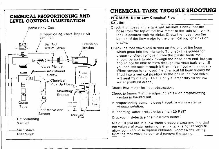
HEMICAL PROPORTIONING ANDEVEL CONTROL ILLUSTRATION
Valve Body Cap/
/
Proportioning Valve Repair Kit
000078/
0’;?
/Ball Nut ExtensionW/Set Screw Bracket
-z
‘—>%EI-+Z
\ i
To
Valve Plunger ~~1)
—F’ +------Adjustment
ScrewFloat
“F7J
Assm.-Chemical
Pick Up Hose,. - 1
8> [Mounting ~. wL
Bracket I
@
.
? ‘!q
‘- iOutlet
tFloat
Tube -“+[LFoot Valve and ._& !L—
Screen ,,/Underwater
—ProportioningFeed
Venturi
—Main ValveDiaphragm
CHEMICAL TANK TROUBLE SHOOTINGPROBLEM: No or Low Chemical Flow
Solution
Check that hoses in the tank are secured. Check that thehose from the top of the flow meter to the s[de of the mixtank is secured with no kinks. Check the hose from thebottom of the flow meter to the chemical jug for kinks orcracks.
Check the foot valve and screen on the end of the hosewhich goes into the mix tank. To check this screen for
proper function, remove it from the plastic hose. Youshould be able to suck through the hose barb end, but you
should not be able to b[ow through the hose barb end. (Ifyou can not suck through it then rinse it out with vinegar. )When screen IS removed the chemical fill hose should belifted into a vertical position so the ball [n the foot valve
will seat by grawty. (This IS only a temporary fix for lowwater pressure areas. )
Check flow meter for float obstruction
Check to insure that the adjusting screw on proportioningventuri is backed out.
Is proportioning ventun closed? Soak [n warm water orvinegar solution.
Is incoming water pressure less than 20 PSI?
Cracked or defective chemical flow meter? I
NOTE: If you are in a low water pressure area and find that
the volume of water entering the mix tank is not enough toallow your venturi to siphon chemical, unscrew the springfrom the foot valve screen and remove the spring.— —.

PROBLEM: Inability to Adjust Chemical with the Flow Meter
Solution
Debris lodged behind teflon seat in flow meter knob.
Teflon seat dismounting from flow meter knob.
PROBLEM: Solution Reversing from Mix Tank to ChemicalJua
Solution
Anti-siphon screen removed from chemical jug hose.
Debris in anti-siphon screen.
PROBLEM: Mix Tank Overflows
Solution
Float ball in mix tank hanging up (not moving freely)
Extension bracket pinching the float lever, restricting fullaction of the lever.
Plunger not seating properly on the valve. (Remove the 2screws which hold the extension assembly to the valve.Do not lose or drop the screws, Remove the extensionassembly. Turn it upside down. Inspect the plunger forproper seating. If there is no debris obstructing the valve
or plunger, the plunger may be out of adjustment. To ad-just, loosen the set screw on the ball nut and move theball toward the end of the rod 1/16”. Retighten set screw.Place extension assembly back into position. Tighten thetwo screws.
PROBLEM: Mix Tank Doesn’t KeeD UP With Water OutRut
Solution
Check garden hose quick connect assembly screen.
Check garden hose and/or feed hose to the mix tank for clog,kinks or blockage.
Float ball in mix tank hanging up. (Not moving freely. )
Extension bracket pinching float lever, restricting full action oflever.
Valve plunger not opening fully, To adjust, remove the 2screws which hold the extension assembly to the valve.(Do not lose or drop the screws.) Remove the extensionassembly, turn it up side down. To adjust, loosen the setscrew on the ball nut. Place your thumb on the plungerand press it in 1 /1 6“ and slide the ball nut w/set screwtoward the plunger end 1116”. Tighten the set screw.Place the extension assembly back into position. If thetank starts to overfill, the ball nut is to close to the valveplunger and should be moved back away from the valveplunger slightly.
PROBLEM: PumD Pulsates When The Tank Is in a Fill Mode
Solution
Check that the hose which goes from the gray plastic venturito the bottom of the tank is not directed toward the Catpump pick up port. If it is, aim it in another direction.

Standard GardenHose Screen WithPump-In System
@
@-
@
PuhmmSYSTEM /FLOW ,7DZAGRAM
Incoming WaterConnection
CAT PUMP DIMENSIONS
r ‘2-=-i~----’ 0.20
3
Q+ ~j,1.34[34)-4
\
J
[20]
L-3,1110 ]-&------ lIJ.775)73.5)

IMPORTANT DRIVE INFORMATIONPump speed and pump output in gallons per minute as tabulated isbased upon a 1725 RPM drive motor. Select motor pulley size andprovide GPM of the approximate pump output desired.
Pump RPM and GPM output are approximate values due to varia-tions in pulleys, belts and motors between manufacturers and a& 5“/0 pump output tolerance.
Horsepower figures shown are brake horsepower figures. For gasengine requirements, follow engine manufacturer’s recommenda-tions. In general, use a gas engine with approximately double toelectric motor horsepower.
HORSEPOWER REQUIREMENTS
PRESSURE MOTOR PULLEY SIZEFlow Psl Psl Psl Using 1725 RPM Motor &
I 800 1000 1200 ] Std. Pump Pulley O.D. 1
%EHEEazDETERMINING Rated G.P. M. = “Desired” G.P.tvI.
THE PUMP R.P.M. Rated R.P.M. “Desired” R.P.M.
DETERMINING GPM X PSI = Electric Brake
THE RECJUIREDH.P. 1460 H.P. Required
DETERMINING Motor Pulley O.D. = Pump Pulley O.D.
klOTOR PULLEY SIZE Pump R.P. M. Motor R.P. M.
Note Cons.11 engine manufacturer when using gas or d!esel e.glne
SPECIFICATIONSU.S. Measure Metric Measure
Volume . . . . . . . . . . . ..3 . . . . .. M.5G.P.M. (13 L/M)
Discharge Pressure . . . . . ...1200 P.S.I. (85 BAR)
Max. Inlet Pressure . . ...-8.5 to 40 PS.I. (-0.6 to + 2.8 BAR)
RPM . . . . . . . . . . . . . . . . . . . . . ..12 00 RPM (1200 RPM)
Bore . . . . . . . . . . . . . . . . . . . . . . . . .. O.787° (20 mm)
Stroke, . . . . . . . . . . . . . . . . . . . . . .. O.472° (12 mm)
Crankcase Capacity . . . . . . . . ...10 oz. (.3 L)
Maximum Fluid Temperature, 160°F (71 Oc)
inlet Ports (l) . . . . ..2 . . . . . . . ..l/2’’NPT (1/2” NPT)
Discharge Ports (2) .3/8” NPT (3/8” NPT)
Pulley Mounting . . . . . .Either side (Either side)
Shaft Diameter , . . . . . . . . . . . . ...0.650” (16.5 mm)
Weight . . . . . . . . . . . . . . . . . . . . ..l2.llbs. (5.5 kg)
Dimensions. . . ...10.77” x 9,06” x 5.14” (273,5 x230x 130.5 mm)

PISTON MODEL 290 Exploded View
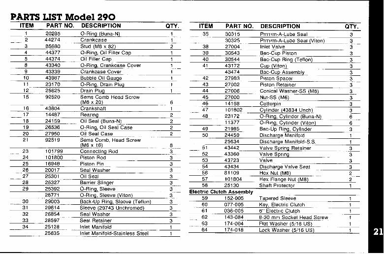
PARTS LIST Mode. ..-ITEM PART NO. DESCRIPTION QTV—.. .
20285 O-Ring (Buns-N) 112 44274 Crankcase 13 85880 Stu4 44377 O-Ring, Oil Filler Cap 15
Jd (M8 X 82) 2
44374 Oil Filler Cap 18 43340 0-Ring, Crankcase Cover 1
9 43339 Crankcase Cover 110 43987 Bubble Oil Gauge 111 23170 O-Ring, Drain Plug 112 25825 Drain Plug 115 92520 Sems Comb Head Screw
(M6 x 20) 616 43804 Crankshaft 117 14487 Rearing 218 24159 Oil Seal (Buns-N) 219 26536 O-Ring, Oil Seal Case 220 27950 Oil Seal Case 221 92519 Sems Comb. Head Screw
(M6 X16) 823 101799 Connecting Rod 324 101800 Piston Rod 325 16948 Piston Pin 328 20017 Seal Washer 327 25301 Oil Seal 328 25327 Barrier Slinger 329 25392 O-Ring, Sleeve 3
28771 O-Ring, Sleeve (Viton) 330 29003 Back-Up Ring, Sleeve (Teflon) 331 29614 Sleeve (29743 Unchromed) ) J
32 26854 Seal Washer 333 28597 Seal Retainer 334 25128 Inlet Manifold 1
25835 Inlet Manifold-Stainless Steel 1
ITEM PART NO. DESCRIPTION QTY.
35 30315 Prrrrrm-A-Lube Seal 330325 Prrrrrm-A-Lube Seal (Viton) 3
38 27004 Inlet Valve 339 30543 Bat-Cup Piston 340 30544 Bat-Cup Ring (Teflon) 341 43172 CuD [Viton) 3
43474 Bat-Cup Assembly 342 27983 Piston Soacer 3
mer 343 27002 Piston Retail; (M8) 344 27006 Conical Washer-S:
45 27000 Nut-SS (h
46 14158 Cotte47 101802 Cylin
me Manifold 1
3 in 3~der (43834 Unch) 3
48 23172 O-Ring, Cylinder (Buns-N) 611377 O-Ring, Cylinder (Viton) 6
49 21985 Bat-Up Ring, Cylinder 350 24459 DischarL _ -..... _ -
25634 Discharge Manifold -S.S, 151 43442 Valve Spring Retainer 352 43360 Valve Spring 353 43723 Valve 354 43434 Dischar!56 81109 He57 101804 Hex Flange f58 25130 Shaft Protector 1
Electric Clutch Assembly59 152-005 Tanererl SleevI? 1
ge Valve Seat 3!X Nut M8 2
Nut (M8) 2
ii 17i-iio4 - ‘-Flat Wa~k
64 174-I-II R
------tric Clutch 1
. ..-60 077-005 - -Key, Elect81 036-005 6“ Electric Clutch 162 143-(-H4 FI-WI mm Socket Head Screw 1
. . . .--,~er (5/16 US) 1---- Lock Washer (5/16 US) 1

SERVICE KITS
30023
36311
303053321
3043133
3361
Cup KitcupO-Ring, CylinderCotterpinInstruction Sheet
Cup Inserter
Seal KitPrrrrrm-A-Lube SealCotterpmAbrasive Paper
Instruction Sheet
Sleeve and Seal KitPrrrrrm-A-Lube Seal
Barrier Slinger
CotterpinSleeveO-Ring, SleeveInstruction Sheet
30686
333331
30860
Valve KitValve Spring RetainerValve SpringValveValve SeatO-Ring, CylinderInstruction Sheet
Piston Kit6 O-Ring, Cylinder
3 Back-Up Ring, Cylinder
3 Bat-Cup Piston
3 Bat-Cup Ring3 cup3 Piston Spacer3 Piston Retainer
3 Conical Washer (M6)
3 Nut (M6)3 Cotterpin3 Inlet Valves1 Instruction Sheet
PUMPING SECTION CUTAWAY
Bat-Cup
Piston Spacer/
I , ,,,,Bac-Cup RingPlsto
cup Iston
colt
‘ut’*nRods’e?/
Cyllnder’

SERVICING THE VALVE ASSEMBLIESDISASSEMBLY:1. Remove the fasteners securing the discharge manifold to the
crankcase of the pump,
2. Support the discharge manifold and tap from the backside anda soft mallet to separate from the crankcase and gradually workfree from cylinders.
3. Valve assemblies will remain in the manifold. Pump modelswith the o-ring groove on the outside of the valve seatrequire the assistance of a reverse pliers to remove thevalve seat. The valve, spring and retainer will then fail out whenthe manifold is inverted.
Pump models without the o-ring groove on the outside of thevalve seat permit the seat, valve, spring and retainer all to fallout when manifold is inverted.
REASSEMBLY:1. Replace retainers in manifold chambers.
2. Next insert spring into center of retainer,
3. Inspect the valves for wear, ridges or pitting and replace ifnecessary.
NOTE: Seating side of flat valves may be lapped on flat sur-face using 240 grit paper. Quiet valves due to their shape mustbe replaced.
Insert valve over spring with recessed (dish) side down.
5. Some pump models have o-rings and back-up rings on thevalve seat. Examine and replace if worn, Always lubricateo-rings for ease of installation and to avoid damagingelastomers.
NOTE: First install o-ring in groove on seat (towards seatingsurface), t~en back-up ring,
NOTE: Models without outer groove on seat require the o-ringto be placed on lip of retainer.
6. Insert valve seats into manifold chambers.
7. Position manifold back onto pump.
NOTE: Lubricate o-rings on cylinder and exercise cautionwhen slipping manifold over cylinders to avoid damagingcylinder o-rings.
8. Replace fasteners and torque per specification chart.
NOTE: Rep/ace all originai shims when used. When newmanifold is used reshim pump.
CAUTION: When starting the pump, check to see that there isno cylinder motion as this will cause premature failure of the
cylinder o-rings. Center cylinder motion can be eliminated byswitching with one of the end cylinders.
4. Next examine the seating surface of the flat valve seats and lapwith 240 grit paper or replace if evidence of excessive wear.
Quiet valve seats should be replaced if worn. Lap new quietvalve and seat to assure positive seal.

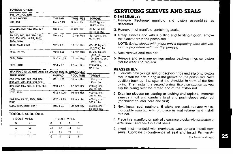
SERVICING THE PUMPING SECTIONDISASSEMBLY:1.
2.
3.
4,
5.
Remove the discharge manifold as described.
Grasp cylinders by hand and with an up and down motion, pullcylinders from inlet manifold.
Remove cotterpin, nut and washer from piston rod.
Next remove retainer, spacer and piston/cup assembly.
Remove inlet valve.
REASSEMBLY:1.
2.
3,
Examine inlet valve surfaces for pitting, scale or grooves.Reverse valve and sand inlet side of valve using 240 grit paperfor clean surface or replace if evidence of excessive wear, Slip
onto rod.
Examine piston seating surfaces and sand clean on flat surfaceusing 240 grit paper. If extreme pitting or sharp edges, replacepiston.
Examine cup for wear, cracking, tearing or separation from thepiston. If worn replace and lubricate before installing on piston.
4
5
6.
7,
8.
NOTE CUP INSTALLATION: Wipe cup inserter with oil. Slip
bat-cup ring (when used) onto piston. Push cup over inserterand square with all surfaces. Faulty cup installation causespremature cup failure.
Lubricate piston assembly and slip onto rod,
Next replace piston spacer and retainer on rod.
Replace washer, thread on nut and torque per specificationchart.
NOTE: Always rep/ace with new Stainless Stee/ Cotferpin andturn ends under.
Examine cylinder walls for scoring or etching which causespremature wear of cups and replace If worn.
Lubricate cylinder and replace o-rings and/or back-up rings ifworn or damaged. Carefully slip cylinders over rod ends and
push into inlet manifold in their original position, (front to back)
Position discharge manifold onto pump, replace fasteners andtorque per specification chart,
17-22 in: Ibs.
250, 260, 300, 420, 500, 524, M5 x 0.9 8 mm Hex 30-55 kg. cm,624
2.26-48 in. Ibs.
20, 260, 260, 290, 320, 333, M6 X1,0 10 mm Hex 50-100 kg. cm. 3.430.530, 550, 10 FR. 1000. 60 in Ibs1024, 1044
--
1020, 1520, 2020 M7x 1.0 10 mm Hex 60-150 kg. cm.52-130 in. Ibs,
2500, 25 FR. M8 X 1,25 13 mm Hex 80.200 kg, cm, 4.130 in. Ibs.
6024, 8044 M1OX 1.25 17 mm Hex 120-250 kg, cm. 5.160 in, Ibs,
6020, 6040 M14 X 1.5 22 mm Hex 200-450 kg. cm.
Remove discharge manifold and piston assemblies asdescribed.
Remove inlet manifold containing seals.
Grasp sleeves and with a pulling and twisting motion removethe sleeves from the piston rod.
NOTE: G[asp sleeve with pliers only if replacing worn sleeves,as this procedure wi// mar the sleeves.
Next remove seal retainer,
Remove and examine o-rings and/or back-up rings on pistonrod for wear and replace.
30 ft. lbe REASSEMBLY:MANIFOLD STUO NUT AND CYLINDER BOLTS WHEN USED
PUMP MOOEL1, Lubricate new o-rinas andlor back-uD rinas and sliD onto Diston
THREAD TOOL SIZE TORQUE
250, 260, 280, 284, 290, 300, M8 X 1,25 13 mm Hex 125 kg. cm.333, 420, 430, 434, 530, 55o 125 m, Ibs.
310, 320, 500, 520, 10 FR,, 650, MIOX 1.5 17 mm Hex 250 kg, cm.1000 217 in. Ibs.
1024, 1044 M12x 1.25 19 mm Hex 400 kg. cm,347 in. Ibs.
2
524, 624, 25 FR, 1024, 1044, M12 x1,75 19 mm Hex 400 kg, cm.2500 385 in, Ibs.
6020, 6024, 6040, 6044 M16 x 2.0 22 mm Hex 650 ka. cm. 2
rod. Install the first fi-ring in the groove ~n the pis~on rod’, Nextposition back-up ring against the shoulder in front of the firsto-ring, Then install the second o-ring. Exercise caution as youslip the o-ring over the thread end of the piston rod,
Examine sleeves for scoring or etching and replace. Immersesleeves in oil and carefully twist and push sleeve onto rod(machined counter bore end first).
. Next install seal retainers. If wicks are used, replace wicks,50-60-fl, Ibs. ‘“ thoroughly saturate with oil, place in seal retainer and install
TORQUE SEQUENCE retainer.
4 BOLT MFLD 8 BOLT MFLD 4. Place inlet manifold on pair of clearance blocks with crankcase
3 2 8135 side down and drive out old seals.
❑ ❑ ❑ oun 5, Invert inlet manifold with crankcase side up and install new•1 El Orion seals, Lubricate circumference of seal and install Prrrrrm-A-
1 4 6427 (continued next page)
6.
7.
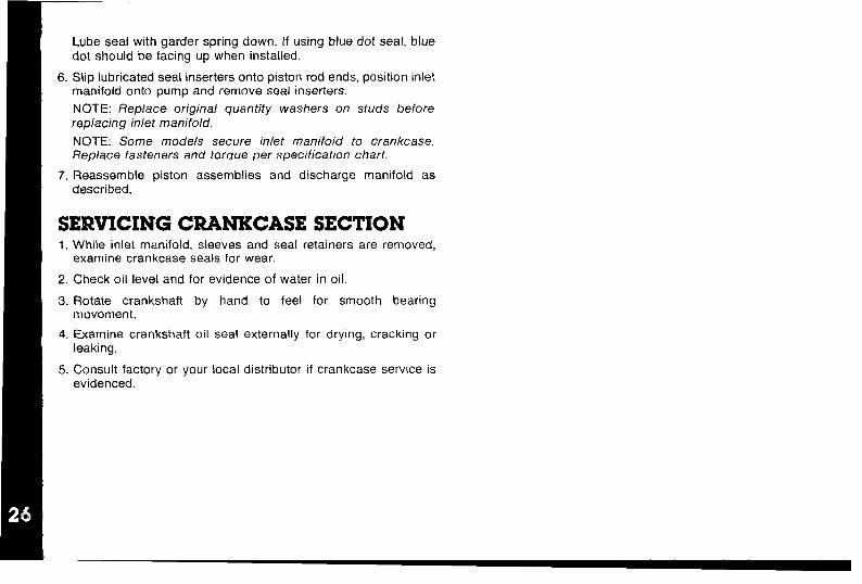
SERVICING CRANKCASE SECTION
Lube seal with garder spring down. If using blue dot seal, bluedot should be facing up when installed.
Slip lubricated seal inserters onto piston rod ends, position inletmanifold onto pump and remove seal inserters.
NOTE: Replace original quantity washers on studs beforerepiacing irriet manifoid.
NOTE: Some models secure inlet manifold to crankcase.Rep/ace fasteners and torque per specification chart.
Reassemble piston assemblies and discharge manifold asdescribed.
1. While inlet manifold, sleeves and seal retainers are removed,examine crankcase seals for wear.
2. Check oil level and for evidence of water in oil.
3. Rotate crankshaft by hand to feel for smooth bearingmovement.
4. Examine crankshaft oil seal externally for drying, cracking orleaking.
5. Consult factory or your local distributor if crankcase service isevidenced.
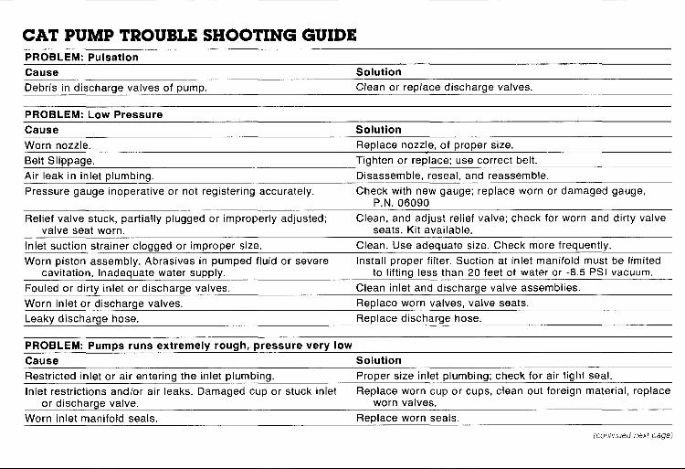
CAT PUMP TROUBLE SHOOTING GUIDEPROBLEM: Pulsation
Cause Solution
Debris in discharge valves of pump. Clean or replace discharge valves.
PROBLEM: Low Pressure
Cause Solution
Worn nozzle. Replace nozzle, of proper size.
Belt Slippage, Tighten or replace; use correct belt.
Air leak in inlet ~lumbina. Disassemble, reseal. and reassemble,
Pressure gauge inoperative or not registering accurately. Check with new gauge; replace worn or damaged gauge,P.N. 06090
Relief valve stuck, partially plugged or improperly adjusted; Clean, and adjust relief valve; check for worn and dirty valvevalve seat worn. seats. Kit available.
Inlet suction strainer clogged or improper size, Clean. Use adequate size, Check more frequently.
Worn piston assembly. Abrasives in pumped fluid or severe Install proper filter. Suction at inlet manifold must be limited
cavitation. Inadequate water supply. to lifting less than 20 feet of water or -8.5 PSI vacuum.
Fouled or dirtv inlet or discharae valves. Clean inlet and discharae valve assemblies.
Worn inlet or discharge valves. Replace worn valves, valve seats.
Leakv discharae hose. FieDlace discharae hose.
PROBLEM: Pumps runs extremely rough, pressure very low
Cause Solution
Restricted inlet or air entering the inlet plumbing. Proper size inlet plumbing; check for air tight seal.
Inlet restrictions and/or air leaks. Damaged cup or stuck inlet Replace worn cup or cups, clean out foreign material, replace
or discharge valve. worn valves.
Worn inlet manifold seals. Replace worn seals.
(continued next page)

CAT PUMP TROUBLE SHOOTING GUIDE (continued)
PROBLEM: Cylinder O-rings blown next to discharge manifold
Cause Solution
Pressures in excess of rated PSI.——
Check for plugged nozzle, closed valves or improperlyadiusted bv-oass valve.
Warped manifold. Replace manifold.——
PROBLEM: Leakage at the cylinder O-rings at the discharge manifold and black, powdery substance in the area of theO-rirms
Cause Solution
Loose cylinders, Cylinder motion caused by improper Remove spacer shims on manifold studs. Do not remove tooshimming of the discharge manifold. many shims or the ears of the manifold will be bowed
when the manifold is retightened, causing looseness inthe center cylinder. —...
PROBLEM: Water leakage from under the inlet manifold
Cause Solution
Worn inlet manifold seals, Leaking sleeve O-ring. Install seals. If piston rod sleeve; are scored, replace sleeves”
and sleeve Cl-rings. _...-...-—.
PROBLEM: Oil ieak between crankcase and pumping section
Cause Solution
Worn crankcase oiston rod seals. ReDlace crankcase piston rod seals
Excess oil from wicks. Reduce quantity of oil per oiling. .—
PROBLEM: Oil leaking in the area of Crankshaft
Cause Solution
Worn crankshaft seal or improperly installed oil seal retainer Remove oil seal retainer and replace damaged gasket and/or
Dackino. seals.

PROBLEM: Oil leaking in the area of Crankshaft
Cause Solution
Bad bearing. Replace bearing.
PROBLEM: Excessive play in the end of the crankshaft pulley
Cause Solution
Worn main ball bearing from excessive tension on drive belt. Replace ball bearing. Properly tension belt.
PROBLEM: Water in crankcase
Cause Solution
May be caused by humid air condensing into water inside the Change oil at 3 month or 500 hour intervals using Cat Pumpcrankcase. Crankcase Oil (other approved oil every month or 200
hours) P. N.: 06100,
Leakage of manifold inlet seals and/or piston rod sleeve Replace seals, sleeve and O-rings,O-ring.
PROBLEM: Oil leaking from underside of crankcase
Cause Solution
Worn crankcase piston rod seals. Replace seals, sleeve and O-rings,
PROBLEM: Oil Ieakina at the rear ~ortion of the crankcase
Cause Solution
Damaged or improperly installed oil gauge or crankcase rear Replace oil gauge or cover O-ring, and drain plug O-ring.cover O-ring, and drain plug O-ring.
PROBLEM: Oil leakage from drain plug
Cause Solution
Loose drain plug or worn drain plug O-ring Tighten drain plug or replace O-ring.(continued next page)
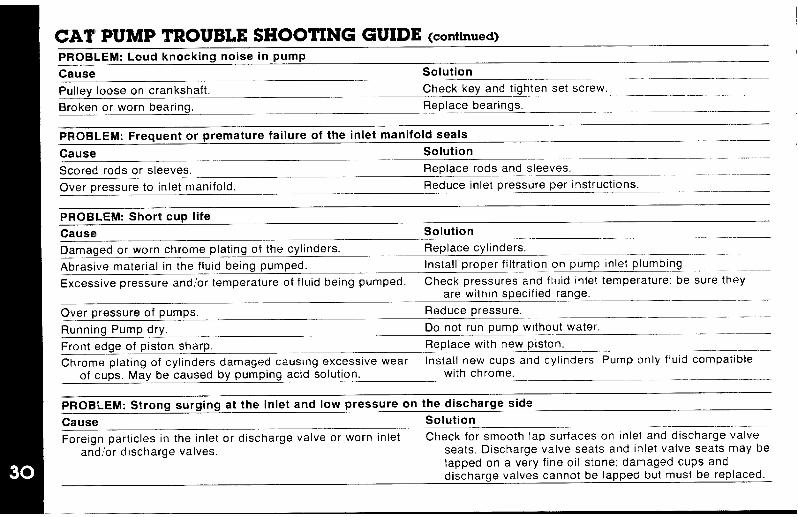
CAT PUMP TROUBLE SHOOTING GUIDE (continued)
PROBLEM: Loud knocking noise in pump
Cause Solution
Pulley loose on crankshaft. Check key and tighten set screw.
Broken or worn bearing. Replace bearings.
PROBLEM: Frequent or premature failure of the inlet manifold seals
Cause Solution
Scored rods or sleeves._—.—
Replace rods and sleeves.
Over pressure to inlet manifold. Reduce inlet pressure per instructions.
PROBLEM: Short cup life
Cause Solution
Damaged or worn chrome plating of the cylinders.
—. .—Replace cylinders.
Abrasive material in the fluid being pumped. Install proper filtration on p~mp Inlet plumbing
Excessive pressure and/or temperature of fluid being pumped. Check pressures and fluid inlet temperature: be sure theyare within specified range.
Over pressure of pumps. Reduce pressure.
Running Pump dry. Do not run pump without water.
Front edge of piston sharp. Replace with new piston.
Chrome plating of cylinders damaged causing excessive wear Install new cups and cylinde~s, Pump only fluid compatible
of cups. May be caused by pumping acid solution. with chrome.
PROBLEM: Strong surging at the inlet and low pressure on the discharge side
Cause Solution
Foreign particles in the inlet or discharge valve or worn inlet Check for smooth lap surfaces on inlet and discharge valve
andlor discharge valves. seats. Discharge valve seats and inlet valve seats may belapped on a very fine oil stone; damaged cups anddischarge valves cannot be lapped b~t must be replaced.
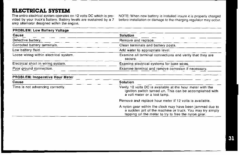
ELECTRICAL SYSTEMThe entire electrical system operates on 12 volts DC which is pro- NOTE: When new battery is installed insure it is properly chargedvialed by your truck’s battery. Battery levels are sustained by a 7 before installation or damage to the charging regulator may occur,amp alternator designed within the engine.
PROBLEM: Low Battery Voltage
Cause Solution
Defective battery. Remove and replace.
Corroded battery terminals. Clean terminals and battery posts.
Low battery fluid. Add water to appropriate level,
Loose wiring within electrical system, Examine all terminal connections and verify that they aresecure.
Electrical short in wiring system. Examine electrical systems for bare wires.
Poor ground connection. Examine terminal and remove corrosion if necessary.
PROBLEM: Inoperative Hour Meter
Cause Solution
Time is not advancing correctly. Verify 12 volts DC is available at the hour meter with theignition switch turned on. This can be accomplished witha volt meter or a test lamp.
Remove and replace hour meter if 12 volts is available.
A nylon gear within the clock may have been jammed due toa sudden jolt of the machine or truck. You may try simplytapping on the meter to try to free the nylon gear.
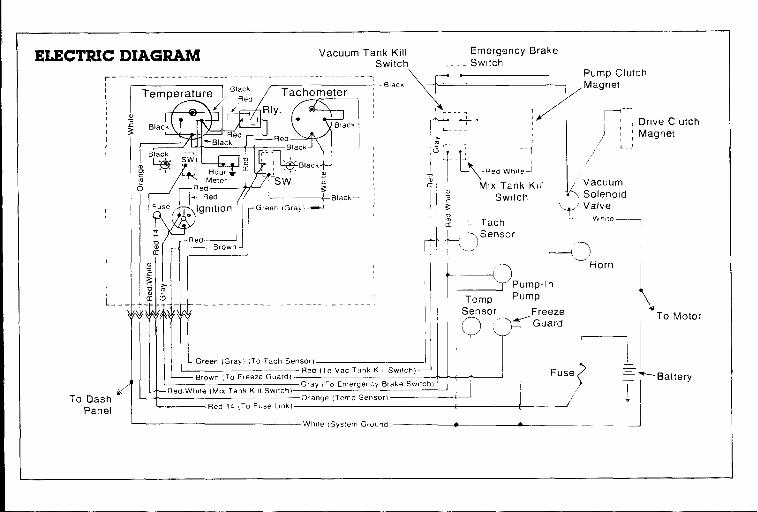
ELECTRIC~-11
IIIII(,
1
I
1(1t
I!
1I
[
i_-
r
To DashPanel

I
Any freezing of this machine is not covered by warranty and dur-ing the colder months of operation, careful protection should be ofutmost concern.
THE FOLLOWING PRECAUTIONS ARE RECOMMENDED:
1, Run machine before leaving for the first job to insure nothinghas frozen the night before, including hoses and wand.
2, Insulate the garden hose from the cold ground by running itthrough an extra 1M inch vacuum hose.
3. Leave truck doors closed until time cleaning begins, then openslightly.
4. In colder climates, insulating the truck walls and floor boards willhelp protect the unit.
5. Don’t procrastinate during the cleaning operation or the hotwater solution line will also freeze on the ground. The solutionline should be insulated in extremely cold climates.
6. Whenever possible, the truck should be stored in a heatedgarage at night or over the weekend, If not possible, place a1500 watt electric heater inside the truck, aimed directlyat the machine, Never use a propane heater - it causes ex-cessive moisture on the truck ceiling and the possibility of itgoing out is higher, If the machine and truck are left outside witha heater, you should first drain all possible water from themachine cleaning tools and hoses. (They freeze also.)
TO DRAIN THE MACHINE, FOLLOW THESE STEPS:
A. Before shutting off the machine, remove the chemical line fromthe chemical jug and place in a mixture of 50/50 anti-freeze andwater. With the cleaning tool on, allow mixture to fill chemicalsystem back to the chemical mix tank.
B. Open the mix tank drain valve and allow the water to drainthoroughly from the mix tank.
C. To remove the water from the heat exchanger and pump usethe freeze guard which is a small air compressor. Using the cor-rect connectors, first blow air into the high pressure solutionmale quick connect. This will force the water through the heatexchanger back through the pump and into the chemical mixtank to be drained out through the petcock valve to the ground.By Ioosenirig the bypass knob, the air will be allowed to flowmore freely through the system. Next, blow the air into the in-coming water quick connect and force that water into thechemical mix tank to be drained out.
Remember to close the drain valve prior to next operation of
your CDS unit.
D.
Check ENGINE Antifreeze regularly,
BE SURE IT’S PROTECTED!Freezing will cause GRIEF, MONEY and DOWN-TIME. Don’tmess with mother nature!
Your mobile carpet cleaning plant has been engineered using thelatest and most sophisticated technology available, to produce thefinest carpet cleaning results possible. Despite this however, it re-mains only a tool of the carpet cleaning trade, and it can produceonly as good a job as the person operating it,
There are no short cuts to good carpet cleaning, it requires time,cleaning knowledge and the use of good chemicals.
Manufacturer recommends the use of spotting agents, and trafficlane cleaners prior to the actual cleaning of carpeting, as required.
CAUTION when cleaning cut-pile acrilan plush carpets: Using highheat setting may result in fiber damage.
(continued next page)

The use of some chemicals through your mobile carpet cleaningplant can seriously damage the internal plumbing. high pressurepump and heater, (Chemical such as concentrated acids andsome paint oil and grease removers wlhigh concentration of
solvents, )
Manufacturer recommends only the use of chemicals containingrust and corrosion inhibitors and water softening agents to prevent
chemical bwld-up.
NOTE: At no time should a chemical solution with pH of less than 7
or higher than 10 be used in the unit.
pH CHART
1 234567891011 12 13 14
J I I I I 1 I 1
~ ACID — NEUTRAL ‘ALKALINE~
CLEANING STROKEPROCEDURE/OVER-WEl’TINGPurpose:To eliminate excess moisture remalnlng in the carpet fiber and thesawtooth appearance which results from diagonal movement ofthe cleaning tool on all types of carpet.
Procedure:Always move the cleaning tool in smooth forward and backwardstrokes. Apply slight pressure to the forward stroke while the solu-tion is injected into the carpet. When extracting (drying), apply firmpressure on the forward stroke to ensure a positive “lock” for thevacuum and min!mlze the “hopping” effect resulting on unsmooth
carpet, During the forward and reverse strokes. movement to theright or left should only be accomplished at the extreme rear of thestroke. Overlapping is also important to ensure even application of
solutlon to prevent saturation when cleaning wand is stopped
twice at the same point at the rear of the cleaning stroke.
Failure to adopt this procedure can result in increased chance of“clean streaks”, fiber shrinkage, brown out, and longer drying
periods.
INCORRECT METHOD CORRECT METHOD
Overlap Between Strokes
pa::;>l=+:=ix’=!
uSeconcf
Cleaning CleaningStroke Stroke
Over-WettingOver-wetting is annoying to all concerned and someilmes leaves abad impression of the cleaning process used.
These are several areas that WIII cause over-wetting:
1, Too few vacuum strokes or Improper saw tooth vacuum strokesas shown above.
2. Obstructed, kinked or cut hoses.
3. Vacuum tank dra[n valve left partially open,
4, Clogged vacuum blower filter or vacuum tank lid not sealingproperly,
5. Cleaning a heavily foam-saturated carpet without defoamer,(We recommend crystal type, )

I
II
MAINTENANCE PROCEDURESTo avoid costly repairs and down-time, it is imperative to developand practice good maintenance procedures from the beginning.These procedures fall into daily, weekly, monthly and quarterly in-crements, and are outlined below. We have provided a
maintenance log for your convenience on page 38; it is recom-mended that you affix a copy of the log on the vehicle door nearyour unit for convenience and to serve as a maintenance reminder.
Daily● Check engine oil level,
“ Inspect garden hose screen - clean as needed.
● Visually inspect machine for loose wires, oil leaks, water leaks,etc.
● Inspect recovery tank s/s filter and filter bag for tears, holes, etc.- clean, repair or replace as needed,
● Lubricate blower with LPS-1 or WD-40 through blower inlet.
Daily: Wipe machine down thoroughly with a damp cloth; flushrecovery tank out thoroughly. Empty filter bag and inspect for rips,tears, etc. - replace as needed; remove, thoroughly clean andreinstall stainless steel filter screen in recovery tank; inspect andclean vacuum slot on cleaning wand; check wand head for sharpedges that could tear carpet - file down as needed; clean wand tomaintain original appearance; wipe down vacuum and highpressure hoses as needed - visually inspect for cuts, etc.
Weekly● Check engine air cleaner filter - clean as necessary.
● Check high pressure pump oil - add as necessary.
● Check pump drive belt for wear - tighten as needed.
● Check pump pulleys - tighten as needed.
● Check lines for wearlchafing.
● Check all nuts and bolts - tighten as needed.
■ Clean vacuum tank thoroughly with high pressure washer.
● Flush water and chemical system with 50/50 white vinegarsolution.
● Check engine RPM’s - adjust to 1200 RPM’s at the pump.
IMPORTANT: Record date and machine hours on maintenancechart.
Monthly● Grease blower bearing fittings.
● Remove pressure bypass valve stem, grease cup and stem,reinstall.
● Check water level in battery. Clean connections as needed.
IMPORTANT: Record date and machine hours on maintenance
chart.
Quarterly● Change oil in blower (see blower manual).
OVERALL CARE OF UNITMAINTAINING THE ORIGINAL APPEARANCE OF YOUR UNITIS IMPORTANT FOR TWO REASONS:
1
2
It represents a big dollar investment for your cleaning businessand its appearance should reflect that fact. A dirty machine isnot professional!
Maintenance, troubleshooting, and repair is much easier to ac-complish on a clean well m~ntained unit, Regular cleaning ofthe machine offers you an opportunity to visually inspect allfacets of the machine and spot potential problems before theyoccur.

FREEZE PROTECTION OF CLUTCHDRIVE WITH PUMP-IN SYSTEM
1,
2.
3.
4.
5.
Start with machine in cleaning mode.
Drain chemtcal mix tank. (fig. 1)
While chemical mlx tank IS draining: Insert chemical feed hneinto antifreeze premix jug and allow meter to fill with premixant] freeze for 10 seconds. Close chemical flow meter whenprotected. (fig. 2) As shown on page 33 #C.
Shut machine down. Connect short hose to high pressurequick connector and drain heat exchanger of cleaning water.(fig. 3)
Remove pump-in system hose from water storage tank and in-sert it into antifreeze premix jug. (fig. 4)
.*,,
mIIP’’--’wB
6
7.
8
9
Close chemical mix tank drain valve and allow pump-in systemto refill mlx tank with anhfreeze premix solution. (fig. 5)
Start unit with cleanlng wand and hoses connected and sprayInto a bucket for 20 seconds to allow the armfreeze to protect[he high pressure gauge and system lines. After runmng thewand spray for 20 seconds, shut wand oft and let It run for10 seconds to allow the bypass system to be protected. (fig. 6)
Turn off cleanlng system Master Power Switch You may wanlto leave the pump-in hose out of the tank so Ii won’t freeze tothe residual water in the tank. The next day, refill the tank andreplace the hose. If layer of ce, the hose WIII slt on top of It and
gain proper suction.
Reconnect pump-in hose to water storage tank.
Fig. 1 Fig, 2 Fig. 3 Fig. 4
— ———
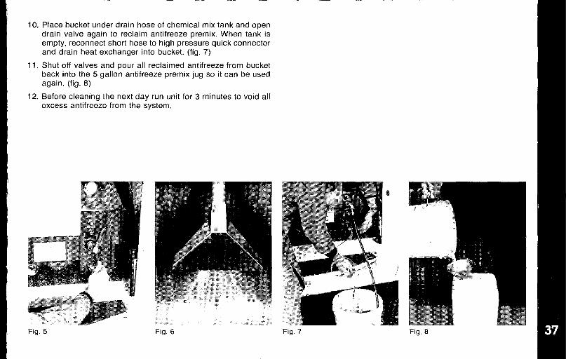
10. Place bucket under drain hose of chemical mix tank and opendrain valve again to reclaim antifreeze premix. When tank isempty, reconnect short hose to high pressure quick connectorand drain heat exchanger into bucket. (fig, 7)
11. Shut off valves and pour all reclaimed antifreeze from bucketback into the 5 gallon antifreeze premix jug so it can be usedagain. (fig. 8)
12. Before cleaning the next day run unit for 3 minutes to void allexcess antifreeze from the system.
Fig. 5 Fig. 7 Fig, 8

I
I
I
I
I
I
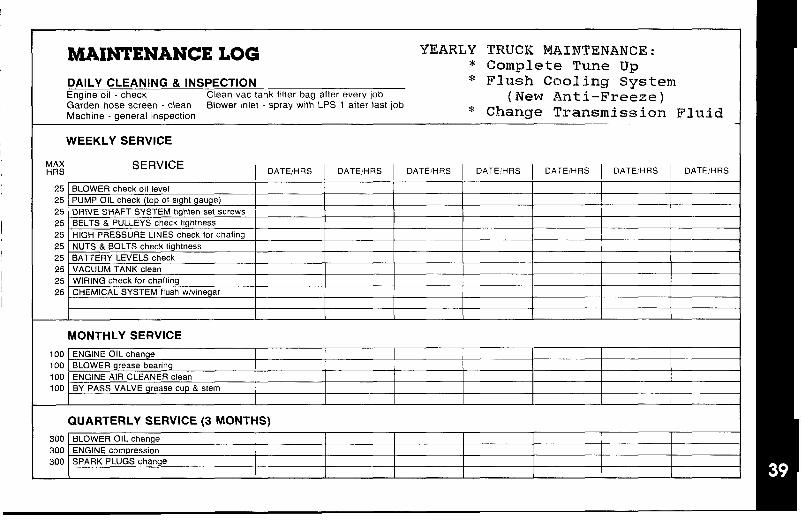
MAINTENANCE LOG YEARLY TRUCK MAINTENANCE:* Complete Tune WI
DAILY CLEANING &lNSPECTION
.* Flu&h Ca~ling System
Engine oil - check Clean vactank filter bag affer every job (New Anti-Freeze)Garden hose screen -clean Blower mlet-spraywtth LPS 1 after last]obMachine -general inspection * Change Transmission Fluid
WEEKLY SERVICE
MAXHRS
SERVICE I DATE/HRS I DATEHRS I DATEIHRS I DATEHRS I DA~,!HRS I ~A~~HRS I DATE/HRS
25 BLOWER checkoll level25 PUMP OIL check (top of sight gauge)25 DRIVE SHAFT SYSTEM tighten set ecrews25 BELTS & PULLEYS check ttghtnees25 HIGH PRESSURE LINES check for chafing25 NUTS & BOLTS check tightness25 BATTERY LEVELS check25 VACUUM TANK clean25 WIRING check for chafting25 CHEMICAL SYSTEM flush wlwnegar
MONTHLY SERVICE
100 ENGINE OIL change100 BLOWER grease bearing100 ENGINE AIR CLEANER clean100 BY PASS VALVE grease cup& stem
QUARTERLY SERVICE (3 MONTHS)
300 ❑LOWER OIL change300 ENGINE compression300 SPARK PLUGS change
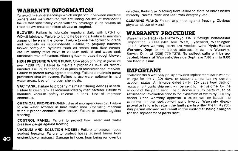
WARRANTY INFORMATIONTo avoid misunderstandings which might occur between machineowners and manufacturer. we are listing causes of componentfailure that specifically voids warranty coverage. Such causes as
listed below shall constitute abuse or neglect.
BLOWER: Failure to lubricate impellers daily with LPS-1 orWD-40 lubricant. Failure to lubricate bearings. Failure to maintainproper oil levels in the blower. Failure to use the correct oil grade
and viscosity as recommended. Failure to properly maintainblower safeguard systems such as waste tank filter screen,vacuum safety relief valve in vacuum tank lid and waste tankautomatic shut-off system, Allowing foam to pass through blower.
HIGH PRESSURE WATER PUMP: Operation of pump at pressureover 1200 PSI. Failure to maintain proper oil level as recom-
mended. Failure to change oil in pump at recommended intervals.Failure to protect pump against freezing. Failure to maintain pumpprotection shut-off system. Failure to use water softener in hardwater areas. Use of improper chemicals.
VAC TANK: Failure to properly maintain filtering devices in tank.Failure to clean tank as recommended by manufacturer. Failure tomaintain vacuum safety release in tank. Use of improperchemicals.
CHEMICAL PROPORTIONER: Use of improper chemical. Failureto use water softener in hard water area. Operating machinewithout proper chemical filter screen. Failure to protect againstfreezing.
CONTROL PANEL: Failure to protect flow meter and waterpressure gauge against freezing.
VACUUM AND SOLUTION HOSES: Failure to protect hosesagainst freezing. Failure to protect hoses against burns from
engine/blower exhaust, Damage to hoses from being run over by
vehicles. Kinking or cracking from failure to store orcorrectly. Normal wear and tear from everyday use.
unroll hoses
CLEANING WAND: Failure to protect against freezing. Obviousphysical abuse of wand.
WARRANTY PROCEDUREWarranty coverage is available to you ONLY through HydraMaster
Corporation, 20309 64th Ave. West, Lynnwood, Washington98036. When warranty parts are needed, write HydraMasterWarranty Dept. at the above address, or call the Warranty
Service Dept. at (206) 775-7275. No collect calls will be ac-cepted. Hours of Warranty/Service Dept. are 7:001 am to 6:00pm Pacific Time.
IMPORTANTHydraMaster’s warranty policy prowdes replacement parts withoutcharge for thirty (30) days to customers ma~ntaining currentaccount status, An invo[ce dated thirty (30) days from date ofreplacement parts shipment WIII be sent to the customer for theamount of the parts sent. The customer’s faulty parts must bereturned for evaluation prior to the expiration of the thirty (30) dayperiod, Upon warranty approval. a credit WIII be issued thecustomer for the replacement parts Invoice. Warranty cfisap-proval or failure to return the fauity parts within the thirty (30)day period allowed will result in the customer being chargadfor the replacement parts sent.
I
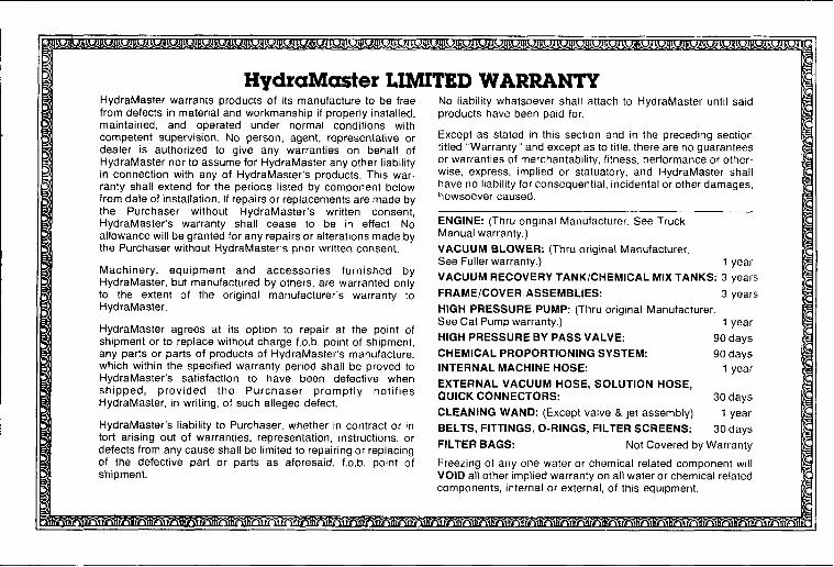
HydraMaster LIMITED WARRANTYHydraMaster warrants products of its manufacture to be freefrom defects in material and workmanship if properly installed,maintained, and operated under normal conditions withcompetent supervision, No person, agent, representative ordealer is authorized to give any warranties on behalf ofHydraMaster nor to assume for HydraMaster any other liabilityin connection with any of HydraMaster’s products. This war.rarity shall extend for the periods listed by component belowfrom date of installation, If repairs or replacements are made bythe Purchaser without HydraMaster’s written consent,HydraMaster’s warranty shall cease to be in effect, Noallowance will be granted for any repairs or alterations made bythe Purchaser without HydraMaster’s prior written consent.
Machinery, equipment and accessories furnished byHydraMaster, but manufactured by others, are warranted onlyto the extent of the original manufacturer’s warranty toHydraMaster,
HydraMaster agrees at its option to repair at the point ofshipment or to replace without charge f.o.b. point of shipment,any parts or parts of products of HydraMaster’s manufacture,which within the specified warranty period shall be proved toHydraMaster’s satisfaction to have been defective whenshipped, provided the Purchaser promptly notifiesHydraMaster, in writing, of such alleged defect.
HydraMaster’s liability to Purchaser, whether in contract or intort arising out of warranties, representation, instructions, ordefects from any cause shall be limited to repairing or replacingof the defective part or parts as aforesaid, f.o.b. point ofshipment.
No liability whatsoever shall attach to HydraMaster until saidproducts have been paid for.
Except as stated in this section and in the preceding sectiontitled “Warranty” and except as to title, there are no guaranteesor warranties of merchantability, fitness, performance or other-wise, express, implied or statutory, and HydraMaster shallhave no liability for consequential, incidental or other damages,howsoever caused,
ENGINE: (Thru original Manufacturer. See TruckManual warranty, )
VACUUM BLOWER: (Thru original Manufacturer,See Fuller warranty.) 1 year
VACUUM RECOVERY TANK/CHEMICAL MIX TANKS: 3 years
FRAME/COVER ASSEMBLIES: 3 years
HIGH PRESSURE PUMP: (Thru original Manufacturer.See Cat Pump warranty,) 1 year
HIGH PRESSURE BY PASS VALVE: 90 days
CHEMICAL PROPORTIONING SYSTEM: 90 days
INTERNAL MACHINE HOSE: 1 year
EXTERNAL VACUUM HOSE, SOLUTION HOSE,QUICK CONNECTORS: 30 days
CLEANING WAND: (Except valve & jet assembly) 1 year
BELTS, FITTINGS, O-RINGS, FILTER SCREENS: 30 days
FILTER BAGS: Not Covered by Warranty
Freezing of any one water or chemical related component willVOID all other implied warranty on all water or chemical relatedcomponents, internal or external, of this equipment.