how to reduce vibration metal cutting
TRANSCRIPT

How to reduce vibration in metal cutting
Sandvik Coromant – How to reduce vibration in metal cutting
Turning - Rotating
Introduction
Vibration in metal cutting is familiar to every machine tool operator. This phenomena is recognised in operations such as internal turning, threading, grooving, milling, boring and drilling, to which there are several reasons why this problem occurs. Some are related to the machine tool itself, to the clamping of the tool, the length and diameter of the tool holder and the cutting data to be used. More of this will be discussed later.There will be several different actions to consider when solving this pro-blem. Reducing the process parameters is one such consideration, however, this could have a negative effect on productivity. Our focus, therefore, will be easy hands on recommendations for productive solutions and easy to use products. This strategy will be emphasized throughout this guide which will also contain useful information relating to the tool holder e.g. clamping methods, extensions and the types of inserts that can be used.
Stretching beyond the normal limit of 4 x the L/D (Length by Dia- meter) ratio is possible when using a Silent Tools tool holder.
Silent Tools is a Trade Mark for a family of tool holders for turning, milling, boring and drilling with a damper inside to minimise the problems with vibration. You will find more information about these damped adap-tors in a separate chapter. Products with a similar function can be referred to as tuned, damped or anti-vibration tools.
The aim, with this application on hand, is for you to have easy access to information giving you productive solutions for eliminating vibrations in your metal cutting process.
For further information and assistance, please contact your local Sandvik Coromant representative.

Sandvik Coromant – How to reduce vibration in metal cutting

Sandvik Coromant – How to reduce vibration in metal cutting
Contents
Turning
Practical tips and hints on how to reduce vibrations ................ 02
Select your tool system ................................................................. 04
Turning: hands on information ....................................................07
Threading: hands on information ................................................12
Grooving: hands on information .................................................14
Holding the bar ..............................................................................17
Internal machining theory ............................................................19
Boring very deep holes ..................................................................21
Eliminating vibration with damped boring bars ........................24
Silent Tools
Productivity with slender tools ................................................... 25
Which products have Silent Tools ................................................26
Sandvik Coromant – How to reduce vibration in metal cutting
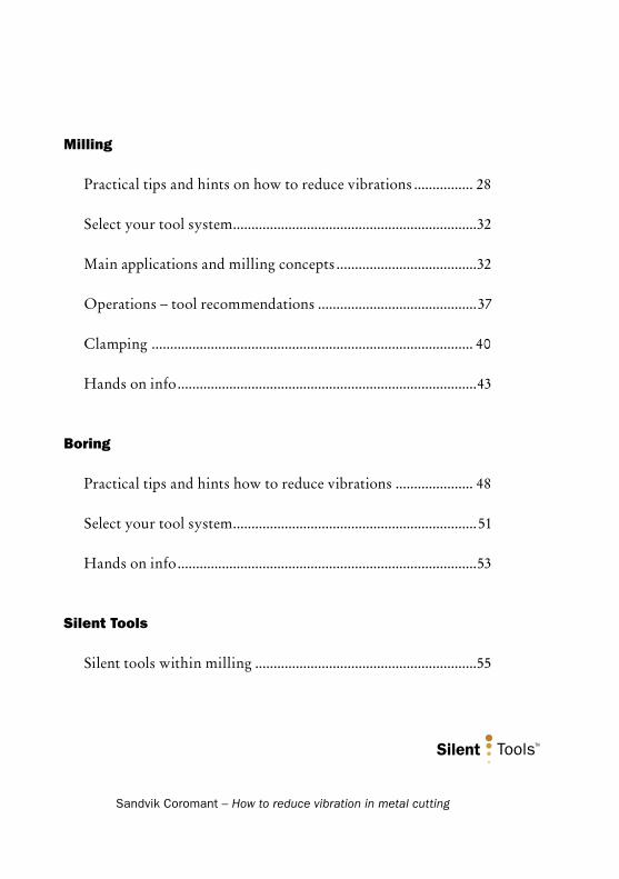
Milling
Practical tips and hints on how to reduce vibrations ................ 28
Select your tool system ..................................................................32
Main applications and milling concepts ......................................32
Operations – tool recommendations ...........................................37
Clamping ....................................................................................... 40
Hands on info .................................................................................43
Boring
Practical tips and hints how to reduce vibrations ..................... 48
Select your tool system ..................................................................51
Hands on info .................................................................................53
Silent Tools
Silent tools within milling ............................................................55

Sandvik Coromant – How to reduce vibration in metal cutting2
TurningPractical tips and hints
on how to reduce vibrations
Chip jamming:1. Increase the coolant flow.2. Change the insert geometry.3. Reduce the cutting speed.
Dimension and tolerance problems:1. Choose a smaller nose radius.2. Choose a more wear resistant grade.3. If there is between 4 x D to 6 x D overhang choose a carbide bar.4. If there is over 6 x D overhang, choose a Silent Tool.

Sandvik Coromant – How to reduce vibration in metal cutting 3
Vibration:1. Choose a smaller nose radius than the depth of cut2. Choose a positive insert with open chip breaker.3. Increase the feed.4. If there is between 4 x D to 6 x D overhang, choose a carbide bar.5. If there is over 6 x D overhang, choose a Silent Tool.
Bad surface finish:1. Increase the coolant flow.2. Choose an insert with a sharp cutting edge.3. Check that all chips have been evacuated.4. Choose a smaller nose radius than the depth of cut.5. If there is between 4 x D to 6 x D overhang, choose a carbide bar.6. If there is over 6 x D overhang, choose a Silent Tool.

Sandvik Coromant – How to reduce vibration in metal cutting4
Select your tool system
One application within metal cutting that is very sensitive to vibration is internal turning. The different tools for the applications have various parameters that can be adjusted to suit the machine, the component and the material.
In this chapter we will talk about the choice of tooling, various appli- cations, how to minimise the risk of vibration and how to improve productivity.
Choosing the correct tool for the applicationDepending on the application and the component, it is important to choose the tool that can give the highest output and security.
Depending on the component diameter there are three Sandvik Coromant systems available to you.
CoroTurn RC with double-sided negative inserts for applications with hole diameters from 20 mm. This system enables applications from fin-ishing to roughing using modern grades and Wiper inserts for increased productivity.
CoroTurn 107 single-sided inserts with seven degree relief angle are designed for turning applications with hole diameters from 8 mm and applications where copying is the main focus.
CoroTurn 111 is a system of inserts with eleven degree relief angle, designed for hole diameters from 6.5 mm - 32 mm where the overhang is generally longer and where there is a need for tools requiring lower cutting forces.

Sandvik Coromant – How to reduce vibration in metal cutting 5
The boring bar families above include insert geometries that are designed for specific applications, such as finish turning of steel materials, roughing in stainless steel machining etc. This is needed to become more productive at every application.
Solid steel bars Recommended for overhangs up to 4 x bar diameter.
Carbide reinforced bars Recommended for overhangs up to 6 x bar diameter.
Carbide reinforced and damped bars Recommended for overhangs up to 10 x bar diameter.

Sandvik Coromant – How to reduce vibration in metal cutting6
CoroTurn SL (type 570)
Modular system for various operations – turning, grooving and threading and holders, including solid steel and Silent Tool holders. Also available are cylindrical bars and Coromant Capto bars. This Coro-Turn SL system of boring bars ranges from 16 mm to 100 mm diameter, and all having the benefit of a quick change system.
CoroTurn, CoroCut and U-lock solid bars
Boring bar programme including Coromant Capto steel bars and cylindrical bars with both steel and carbide bar material. Turning operations possible.
CoroCut MB
Boring bar programme includes steel and carbide bars focusing on grooving operations but also turning and threading operations are possi-ble. Min hole diameter starts at 10 mm.
CoroTurn XS
For internal machining of small bores starting with minimum hole diameter 1 mm. CoroTurn XS enables turning, grooving and threading operations all with one holing system.

ap<rε ap=rε ap>rε∆R
ap
FC [N] FC [N] FC [N]
apap
aprε rε rε
Sandvik Coromant – How to reduce vibration in metal cutting 7
Turning
Choice of insertChoosing the right insert can be enough to eliminate vibration and also improve your manufacturing productivity.
Nose radius:It is important to choose a nose radius that is smaller than the cutting depth as this has the same effect as choosing the correct entering angle. If the nose radius is too large it will push the tool in the radial direction and affect the dimensions of the component.
Wiper inserts act as a large nose radius and will generally need a bit more care when applying to internal turning. To decrease the radial cutting forces it is a normal requirement to increase the feed.
Practical hints:Always choose a smaller nose radius than the cutting depth.

Sandvik Coromant – How to reduce vibration in metal cutting8
Insert size:It is important to choose an insert strong enough to withstand the cutting forces but at the same time it must suit the component and its application. Too large a cutting depth will lead to excessive cutting forces and too small cutting depth will lead to increased friction between the insert and component causing component dimension problems.
Cutting force is extremely important when using long overhangs.
Practical hints:• Do not exceed 2/3 of the cutting edge length when turning as this will
result in too high cutting forces on the cutting edge.
Carbide grade:Generally when turning small holes with small boring bars it is bene- ficial to use sharp inserts as this helps to cut the metal more smoothly.
Sharp inserts need suitable grades, and grades such as the GC1025 and GC4015, have relatively thin coatings that will enhance the cutting action.
Choose a grade according to Sandvik Coromant’s CoroKey matrix.
Steel grades: 4000 series and
5000 series (Cermet inserts)
Stainless grades: 2000 series
Cast iron grades: 3000 series
All round grades: 1000 series
Geometries:Sandvik Coromant geometries are designed and dedicated for each appli- cation area and component materials. Choose your geometry with the application in mind, finishing-roughing, to give the best possible chip breaking together with good machining results.
Steel Materials
Stainless Steel
Cast Iron
Non-ferrous
Super alloys
Hardened materials

Sandvik Coromant – How to reduce vibration in metal cutting 9
Examples of geometry:
- PF: Finshing of steel materials
- PM: Medium machining of steel materials
- PR: Roughing of steel materials
Practical hints:• Choose an open chip breaker, medium chip breaker (PM), instead of
a finishing geometry as the finishing geometry can break the chips too hard and lead to excessive cutting forces resulting in bad surface finish.
Insert style:Depending on the operation – longitudinal turning or copying – the choice of insert style affects the result of the machining process.
Practical hints:• T-style inserts are first choice for internal longitudinal turning as this
style of insert uses an entering angle at 91 degrees. This helps to direct the cutting forces correctly.
• D and V-style inserts both have good copying possibilities and small insert point angles, which help to reduce the force variation.

Sandvik Coromant – How to reduce vibration in metal cutting10
Tool overhangs:Depending on the depth of the hole that needs to be turned, it is important to choose the correct type of tool holder and tool holder material.
Boring bar materials:As seen on the diagram the following boring bar materials can be selected to suit
the length to diameter ratio overhangs.
Steel boring bars: Up to 4 x D
Carbide boring bars: Up to 6 x D
Steel damped boring bars short design: Up to 7 x D Silent Tools
Steel damped boring bars long design: Up to 10 x D Silent Tools
Carbide reinforced damped boring bars: Up to 14 x D Silent Tools
All damped boring bars are called Silent Tools and consist of different variations of tools, the most common being CoroTurn SL (570) system.
Tuned damped bars
/4 = damped part.
Do not clamp on this area. This is indicated on the boring bar.
Max recommended overhang for damped bars, short design 7 x D and long design 10 x D.
Solid bars
Smallest possible overhang.
Max recommended overhang for steel bars 4 x D (/)
Max recommended overhang for Carbide bars 6 x D (/)

Sandvik Coromant – How to reduce vibration in metal cutting 11
Chip evacuation:Chip evacuation during boring is critical to performance and the security of the operation. Relatively short, spiral-shaped chips should be aimed for with internal turning. These are easy to evacuate and do not place such large stresses on the cutting edge when chipbreaking occurs. Hard breaking of the chips, when very short chips are obtained, uses more power and increases vibration. On the other hand, long chips make chip evacuation more difficult and present a risk of swarf-clogging. It is necessary, therefore, to choose an insert geometry which, together with the chosen machining parameters, fulfil the requirements for good chip control.
When internal turning is undertaken, the chip flow can be critical – particularly when deep holes are being machined. The centrifugal force presses the chips outwards which means, with internal turning, that the chips remain in the workpiece. The remaining chips can be pressed into the machined surface or get jammed and damage the tool. It is recommended, therefore, that internal turning tools should have internal coolant supply. The chips will then be flushed out of the hole effectively. Compressed air can be used instead of cutting fluid and by way of through holes, allow the chips to be blown through the spindle and collected in a container.
Chip evacuation is a critical factor for successful boring.

Sandvik Coromant – How to reduce vibration in metal cutting12
Threading
Choosing the correct tool for the application
Choice of tooling family:
T-MAX U-Lock for threading hole diameters from 12 mm
CoroCut MB for threading hole diameters from 10 mm
CoroCut XS for threading hole diameters from 4 mm
Chip evacuation:Chip evacuation is also very important when internal threading, parti-cularly the feed direction which should be from inside out giving better chip control. This, combined with a modified flank infeed, will produce spiral chips which are then led out towards the mouth of the hole. Over-hang, blind holes and material type are also of great importance when internal threading and should be given due consideration.
The infeed per pass should not be more than 0.2 mm and never less than 0.06 mm. Never run a final pass without infeed, and it is important to have a firm force on the bar to minimize vibrations.
Overhang:Compared with turning, threading is limited to a certain overhang due to the increased side (radial) forces. For overhangs beyond 2.5 x D it is recommended to use Silent Tools holders or carbide reinforced shanks to minimize vibration and thus increase productivity.
2 - 2.5 x D solid steel boring bars
3 - 5 x D Silent Tools boring bars
Sandvik Coromant – How to reduce vibration in metal cutting 13
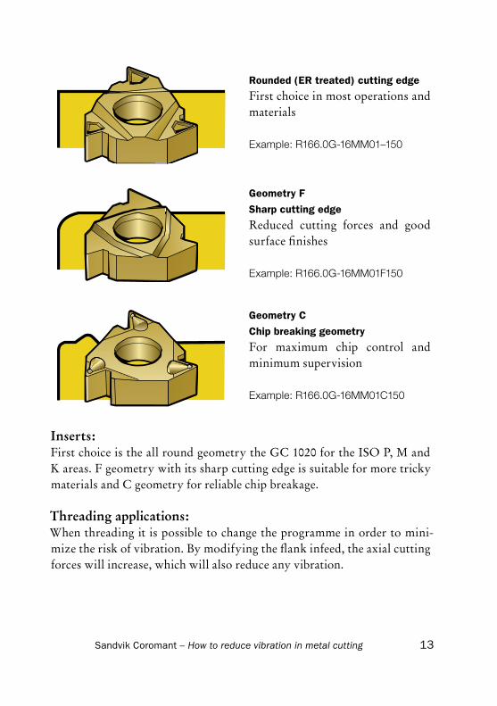
Inserts:First choice is the all round geometry the GC 1020 for the ISO P, M and K areas. F geometry with its sharp cutting edge is suitable for more tricky materials and C geometry for reliable chip breakage.
Threading applications:When threading it is possible to change the programme in order to mini-mize the risk of vibration. By modifying the flank infeed, the axial cutting forces will increase, which will also reduce any vibration.
Rounded (ER treated) cutting edge
First choice in most operations and materials
Example: R166.0G-16MM01–150
Geometry F
Sharp cutting edge
Reduced cutting forces and good surface finishes
Example: R166.0G-16MM01F150
Geometry C
Chip breaking geometry
For maximum chip control and minimum supervision
Example: R166.0G-16MM01C150

Sandvik Coromant – How to reduce vibration in metal cutting14
Grooving
Choosing the correct tool for the application
Choice of tooling family:
CoroCut for grooving hole diameter from 25 mm
T-MAX Q-Cut for grooving hole diameter from 20 mm
CoroCut MB for grooving hole diameter from 10 mm
CoroTurn XS for grooving hole diameter from 4.2 mm
Chip evacuation:To avoid chip jamming within grooving operations it is important to direct the coolant into the groove and evacuate the chips. Chips in the groove can cause insert breakage, bad surface finish or difficulties in keeping tolerances. For this to be effective it is recommended to choose toolholders or cutting heads with integrated coolant.
It is also possible to change the programming of the machine with micro stops so that chip breaking can be achieved and the evacuation of chips is made possible.
Overhang:Compared with turning, grooving is limited to a certain overhang due to the increased side (radial) forces. We recommend, therefore, you choose Silent Tool holders or carbide reinforced so that the productivity can be increased.
2 - 2.5 x D solid steel boring bars
3 - 5 x D Silent Tool boring bars

Sandvik Coromant – How to reduce vibration in metal cutting 15
Inserts:We recommend you use sharp, light cutting inserts with a positive chip breaker such as the CoroCut – CM or GF geometry or the T-Max Q-Cut 5F or 4G geometry. Also it is beneficial to use thin coated inserts which will enable a smooth cutting action and produce a minimal radial force.
Grooving applications:When grooving it is possible to change the application to minimise the risk of vibration by selecting a smaller insert width and making several cuts instead of one. The operation can then be finished with a side turning motion, see fig.
In order to avoid vibrations when machining large, wide grooves, make several
inputs with a narrower insert, (fig A), or groove with a narrow insert and
longitudinal turning (fig B).

Sandvik Coromant – How to reduce vibration in metal cutting16
Problem solving
Chip jamming:• Use the largest possible amount of coolant as this will help to evacuate
the chips from the groove.• Choose a different geometry to reduce the risk of chip jamming.
Dimension problems (tolerances):• Choose a Silent tool holder which will reduce the vibration – max over-
hang is 5 x D.• Choose sharp and positive insert geometry, CoroCut – CM or ground
– GF as it enables a smooth cutting action and minimum deflection from the workpiece.
• Make sure the tool is positioned at correct centre height. The deviation from the workpiece should not be greater than +/- 0.1 mm.
• Have the shortest possible overhang for the application to increase the stiffness of the bar. Max 2 x D for steel bars and max 5 x D for Silent tool bars. A rule of thumb is never to have a tool overhang larger than 8 x la (insert width).
• Choose the largest possible boring bar diameter, to increase stability.
Vibrations (bad surface finish):• Adjust the cutting speed (vc) as the frequency of vibration can change
and the vibration eventually can disappear.• Increase the feed slightly as this can reduce the friction created when
grooving and reduce the cutting action. However, this can increase the deflection (the radial force).
• Choose a thinner insert width and make several cuts, especially for the finishing cut.
• Check the clamping of the boring bar.

Sandvik Coromant – How to reduce vibration in metal cutting 17
Holding the bar
After choosing the boring bar material select the most suitable clamping method for the machine in question.
Stability is the keyword to turn bores to the appropriate criteria such as dimension tolerances and surface finish.
It is essential, for retaining satisfactory results, to clamp the cylindrical boring bar in a split sleeve, as this will have maximum contact area. With EasyFix sleeves the best possible clamping is achieved together with exact centre height positioning.
Achieving correct centre height is one of the most important factors towards gaining maximum benefit from the tool system used, as the centre height affects the rake angle and cutting force on the tool.
Using screws directly in contact with the cylindrical boring bar will not give satisfactory results and maximum performance of the boring bar will not be achieved.
Clamping method Stability
Cylindrical boring bars in split sleeve: ++
Boring bars with flats: +
Coromant Capto boring bars: ++
Cylindrical boring bar with screw clamping: --
(-- = not recommended + = adequate, ++ = very good)
Practical tips:• Use Coromant Capto for its efficient function, good stability and also
for the benefits of a quick change system.• If you are using a cylindrical boring bar, always us split sleeves such as
EasyFix giving an exact centre height.
On Silent Tool boring bars it is important not to clamp on the dampening part of the bar. For measurement information see the main turning cata-logue and dimension l4.
Good clamping of boring bars is a very important factor in all turning
Sandvik Coromant – How to reduce vibration in metal cutting18
operations in order to achieve the best results. It is particularly important when working with overhangs stretching beyond 4 times the L/D ratio.
Sandvik Coromant also offers a full programme of conventional tool holders.
Clamping with EasyFix sleeves for cylindrical bars:EasyFix gives a fast and simple way to achieve correct indexing of centre height when mounting cylindrical bars into the machine, due to its spring loaded plunger design. Three EasyFix sleeves are available for clamping small 5-25 mm boring bars.
CoroTurn SL Boring Bars:All boring bars have through-tool coolant supply via slots, on bars having diameters of 16 to 25 mm and through holes on the 32 to 60 mm range.
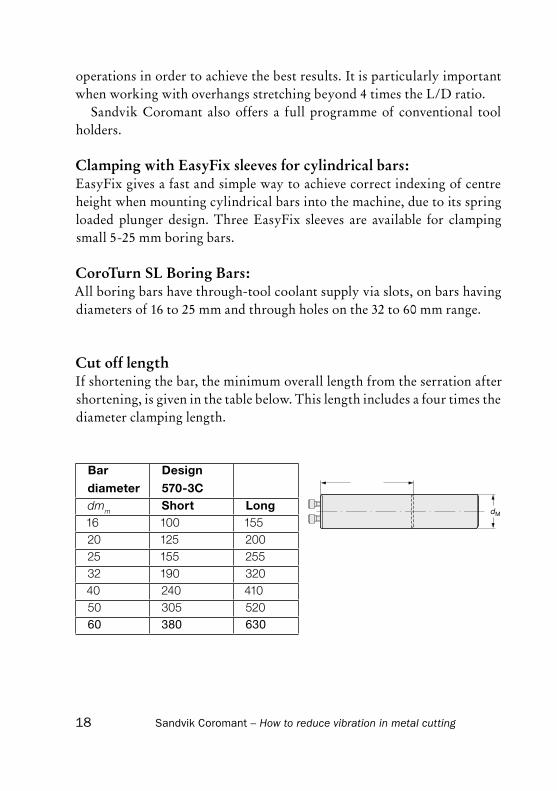
Cut off lengthIf shortening the bar, the minimum overall length from the serration after shortening, is given in the table below. This length includes a four times the diameter clamping length.
Bar
diameter
Design
570-3Cdmm Short Long16 100 15520 125 20025 155 25532 190 32040 240 41050 305 52060 380 630

Sandvik Coromant – How to reduce vibration in metal cutting 19
Internal machining theory
Internal turningMany external turning operations are also found in boring, as per-formed with stationary turning tools, (as opposed to boring operations with rotating tools, such as in machining centres). With external turning, the tool overhang is not affected by the length of the work-piece and the size of the tool holder can be chosen so that it with-stands the forces and stresses which arise during the operation. With boring - internal turning - the choice of tool is very much restricted by the component’s hole diameter and length as the depth of the hole determines the overhang.
A general rule, which applies to all machining, is to always minimize tool overhang and to select the largest possible tool size in order to obtain the best possible stability and thereby accuracy. Stability is increased when a larger boring bar diameter is used, but possibilities are often limited, since the space allowed by the diameter of the hole in the component must be taken into consideration for swarf evacuation and any radial movement.
The limitations with regard to stability in boring mean that some extra care must be taken with production planning and preparation. Selecting the right boring bar for the operation, applying it correctly and clamping it properly has considerable effect on keeping tool deflection and vibration to a minimum, and consequently the quality of the hole being machined.
Sandvik Coromant – How to reduce vibration in metal cutting20
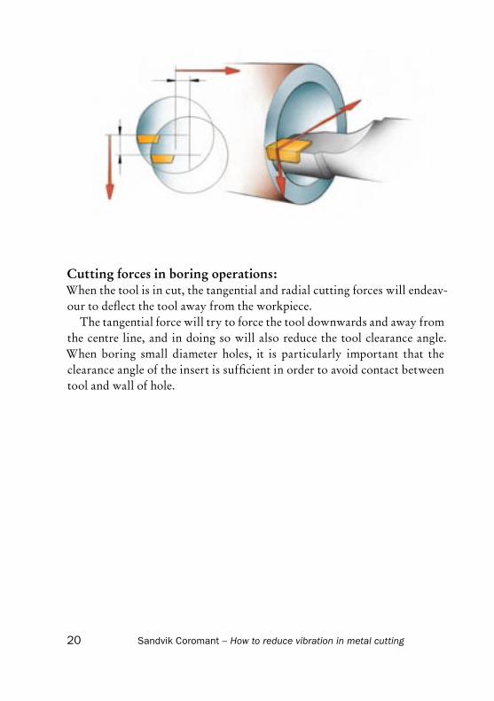
Cutting forces in boring operations:When the tool is in cut, the tangential and radial cutting forces will endeav-our to deflect the tool away from the workpiece.
The tangential force will try to force the tool downwards and away from the centre line, and in doing so will also reduce the tool clearance angle. When boring small diameter holes, it is particularly important that the clearance angle of the insert is sufficient in order to avoid contact between tool and wall of hole.

Sandvik Coromant – How to reduce vibration in metal cutting 21
Boring very deep holes
The internal machining of large diameter holes, deep holes and a combina-tion of both usually needs tool solutions where stability during machining is maximized through combinations of tool solutions. In addition to basic points such as maximum bar diameter; sufficient chip evacuation; positive insert geometry; 90 degree entering angle; correct insert shape; small nose radius and sharp cutting edge; special tool features may need to be consid-ered to provide the boring bar with every weapon there is against vibration tendencies, especially when tolerances are close and surface finish is an issue.
Stability starts at the back end, where the boring bar is clamped in the machine. Coromant Capto or complete encasement of the bar in a sleeve should always be the case.
Tool clamping at the front end and back end are important performance factors for machining with long boring bars.

Sandvik Coromant – How to reduce vibration in metal cutting22
When discussing tool overhangs of 10 times the diameter or more, damped boring bars and carbide re-inforcement should be considered or a combination of both. The cutting unit coupling is a critical link and needs to be beyond any risk of instability. The front end should also be characterized by low weight. This means that if there is scope for diameter reduction of the cutting unit or the last part of the bar, this is worth conside-ring. It is the back end and the main part of the boring bar that should be as large as the operation permits – even tapered bars are suitable for some applications.
CoroTurn SL with radial adjustment.
The CoroTurn SL (570 coupling) provides the means for high stability, diameter reduction, quick change of the cutting unit and radial adjust-ment of the cutting edge (f1 dimension). Bar diameters of over 40 mm have adaptors which reduce the coupling to accommodate the large 40 mm dia-meter range of cutting units.

Sandvik Coromant – How to reduce vibration in metal cutting 23
Eliminating vibrationwith damped boring bars
The usual cause of vibrations during machining is the dynamic interaction between the cutting process and the machine tool structure. The source is the variation of cutting force generated between the tool and workpiece. This force strains the structure elastically and can cause a deflection of the tool and workpiece, which alters the tool-work engagement. A disturbance in the cutting process, such as a hard spot in the work material, causes a typical deflection which then alters the cutting force. This may then cause the initial vibration to be self-sustaining and to build up with the machine oscillating in one of its natural modes of vibration. A long boring bar over-hang can be a weak link in the set-up involving machine tool, – tool, – work-piece and the source of vibration.
In order to achieve sufficient process stability, the metal removal rate is often reduced or the cutting tool changed. But as productivity is normally a priority in manufacturing, this is the wrong route to go. Instead the means of eliminating vibrations and being able to machine at higher rates should be examined. The use of damped boring bars, with damping elements in-tegrated in the boring bars, improves the dynamic behaviour of the tools, making the process more stable.
Generally, machining up to four times the diameter of boring bars does not cause any problems from the vibration point of view, provided that correct conditions apply as regards cutting data and inserts. With an over-hang of more than 4 times the tool diameter, vibration tendencies can be-come more apparent and damped bars come into the picture as the solution. With a pre-tuned boring bar, machining of holes with a depth of up to 14 times the diameter of the bar can be performed with good results.
An increased length from 4 to 10 times the bar diameter will give a 16 times larger deflection for a bar being subjected to the same cutting force. A further extension from 10 to 12 times the bar diameter, gives another 70 % increase in deflection from the same cutting force. Holding the bar length constant while changing the bar diameter from 25 to 32 mm, reduces deflection by 62% for equal cutting forces. Reduced weight of cutting units

A
BC
Sandvik Coromant – How to reduce vibration in metal cutting24
or the diameter at the front end of the bar will contribute towards mini-mizing the vibration tendency.
Damped boring bars – Silent Tools - include tools that are pre-tuned to the correct frequency in relation to the tool length. This basically means setting up the damped boring bar and the machine to be set up the same as a conventional, solid boring bar.
The pre-tuning system of the damped bar consists mainly of a heavy tuning body (A) with a certain inertia mass, suspended in two rubber bushes (B), one at each end of the tuning body. The tuning body is surrounded by a special oily liquid (C). If vibration tendencies should arise during the machining process using a damped bar, the dampening system will immediately come into force, and the movement-energy of the bar will be absorbed into the tuning system. As a result, vibration is minimized and machining per-formance maintained or improved.
Q. Metal removal rate (cm3/min) 1. Solid steel bar 2. Carbide alloy bar 3. Short, damped bar
4. Long, damped bar 5. Extra long, damped bar
Sandvik Coromant – How to reduce vibration in metal cutting 25
Silent ToolsProductivity with slender tools
When machining deep cavities or with long overhangs you can be faced with vibration problems. One way to overcome this is to reduce the depth of cut, the speed or the feed.
Losing productivity in favour of keeping the process running is not bene- ficial.
Productivity is the number one important issue in being competi-tive. The use of a Silent Tool when going deeper into a bore, will retain, or in many cases improve your productivity. You can keep your depth of cut, the same feed and speed and have a high quality surface finish, closer tolerances and improved tool life even when working with boring bars with overhangs from 7 up to 14 times the bar diameter.
Silent Tools are a family of products for internal turning, milling, boring and drilling. These products are damped to work on overhangs beyond the limitation of solid steel and solid carbide shanks. They are easy to operate and are very flexible due to the wide variety of back-end and front-end couplings.

Sandvik Coromant – How to reduce vibration in metal cutting26
Which products have Silent Tools
Bar dia. 10 - 12 mmCoroTurn 107 and CoroTurn 111 Boring bars
Pre-tuned and easy to use cylindrical boring bars with carbide shaft. Optimum performance in a split sleeve holder. Do not use screws directly onto the bar. Shank diameter 10/12 mm and min. hole Ø 13 / Ø 16 mm. Recommended tool overhang from 6-10 x bar diameter. Integrated tip-seat pocket designed for T or D style inserts.
Bar dia. 16 - 60 mmCoroTurn SL Coromant Capto Boring bars & cylindrical boring bars
Pre-tuned and easy to use Coromant Capto cylindrical boring bars. Coolant through the centre and 570 coupling in front. Coromant Capto C3-C8 back end coupling. Designed for exchangeable (570) cutting heads. Recommended tool overhang from 4-10 x bar diameter.
CoroTurn SL Carbide Reinforced Boring bars
Pre-tuned and easy to use carbide reinforced cylindrical boring bars. Coolant through the centre and 570 coupling in front. Carbide reinforced for increased static stiffness. Optimum performance in a split sleeve holder. Do not use screws directly onto the bar. Designed for exchangeable (570) cutting heads. Recommended tool overhang from 10-14 x bar diameter.
Bar dia. 80-100 mmCoroTurn SL quick change Boring bars
Pre-tuned and easy to use cylindrical boring bars. Coolant through the centre and SL quick change coupling in front. Optimum performance in a split sleeve holder. Designed for exchangeable SL quick change cutting heads or Ø 40 mm 570 cutting heads. Recommended tool overhang from 0-10 x bar diameter.
Sandvik Coromant – How to reduce vibration in metal cutting 27
Bar dia. 80-300 mm580 Carbide Reinforced Boring bars
Tunable carbide reinforced cylindrical boring bars. Coolant through the centre and 580 coupling in front. Shank diameter Ø 80 - Ø 300 mm. Carbide reinforced for increased static stiffness. Do not use screws directly onto the bar. Recommended tool overhang from 10-14 x bar diameter. Designed for flat bed machines. Special tools available for slant bed machines. Reduction adaptor in front makes it possible to use a wide range of cutting units.
580 Boring bars
Tunable cylindrical boring bars. Coolant through the centre and 580 coupling in front. Shank diameter Ø 80 - Ø 300 mm. Recommended tool overhang from 5-10 x bar diameter. Designed for flat bed machines. Special tools available for slant bed machines. Reduction adaptor in front makes it possible to use a wide range of cutting units.
Sandvik Coromant – How to reduce vibration in metal cutting28
Practical tips and hints on how to reduce vibrations
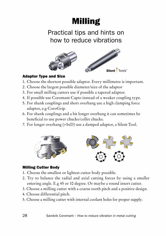
Milling Cutter Body1. Choose the smallest or lightest cutter body possible.2. Try to balance the radial and axial cutting forces by using a smaller
entering angle. E.g 45 or 10 degree. Or maybe a round insert cutter.3. Choose a milling cutter with a coarse tooth pitch and a positive design.4. Choose differential pitch.5. Choose a milling cutter with internal coolant holes for proper supply.
Adaptor Type and Size1. Choose the shortest possible adaptor. Every millimetre is important.2. Choose the largest possible diameter/size of the adaptor3. For small milling cutters use if possible a tapered adaptor.4. If possible use Coromant Capto instead of a weaker coupling type.5. For shank couplings and short overhang use a high clamping force adaptor, e.g CoroGrip.6. For shank couplings and a bit longer overhang it can sometimes be beneficial to use power chucks/collet chucks.7. For longer overhang (>5xD) use a damped adaptor, a Silent Tool.
Milling
Sandvik Coromant – How to reduce vibration in metal cutting 29
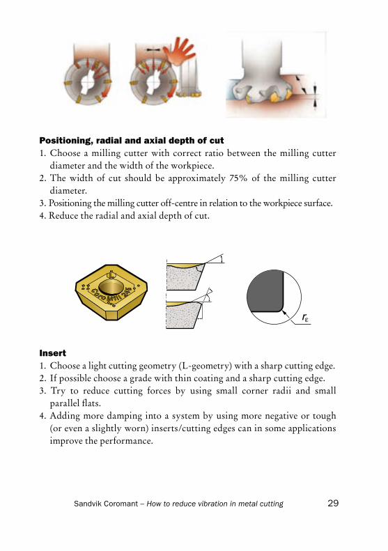
Insert1. Choose a light cutting geometry (L-geometry) with a sharp cutting edge.2. If possible choose a grade with thin coating and a sharp cutting edge.3. Try to reduce cutting forces by using small corner radii and small
parallel flats.4. Adding more damping into a system by using more negative or tough
(or even a slightly worn) inserts/cutting edges can in some applications improve the performance.
Positioning, radial and axial depth of cut1. Choose a milling cutter with correct ratio between the milling cutter
diameter and the width of the workpiece. 2. The width of cut should be approximately 75% of the milling cutter
diameter.3. Positioning the milling cutter off-centre in relation to the workpiece surface.4. Reduce the radial and axial depth of cut.

Sandvik Coromant – How to reduce vibration in metal cutting30
Cutting Data1. If possible try to decrease (or in some cases increase) the cutting speed to
move away from the vibration frequency range.2. Normally increase the feed/tooth. In some cases with unstable condi-
tions it can be better to decrease the feed/tooth.
Down Milling / Up MillingGenerally Down Milling is recommended in almost every milling opera-tion wherever the machine, fixturing and workpiece allows it. But in some cases it can be favourable to use Up Milling to reduce vibration tendencies. Especially when fixturing and/or workpiece is weak in a specific direction.

Sandvik Coromant – How to reduce vibration in metal cutting 31
Machine1. Choose machining strategy and
cutting force directions to take full advantage of the machine stability.
2. Machine condition can have a large influence on the vibration tendencies. Excessive wear of the spindle bearing or feed mecha-nism will result in poor machining properties.
Workpiece1. Affix the workpiece in the most
favourable way to support the cutting forces which arise during the machining process.
2. Use milling concepts with design and entering angle which gene-rate cutting forces in the most stable direction of the workpiece.
3. Optimize the machining strategy and direction to obtain the most stable cutting conditions as possible.

Sandvik Coromant – How to reduce vibration in metal cutting32
Select your tool system
In some specific milling operations vibration tendencies will more or less always occur. Sandvik Coromant offers a lot of different milling concepts for a number of different applications. Each concept has its own specific properties and advantages considering machines, fixturing, components, materials, etc.
Below you will find a short description of each milling concept and a guide to what tool to choose for highest productivity and output.
Main applications and Milling concepts
Shoulder Milling
CoroMill 390
CoroMill 390 - A positive and versatile cutter concept with a very large assortment for all applications from roughing to finishing. It generates a good 90-degree shoulder and is ideal for ramping and helical interpolation. It s also suitable for face milling. Insert grades and geometries for all types of workpiece materials.
Sandvik Coromant – How to reduce vibration in metal cutting 33
CoroMill 290 - A good 90-degree shoulder milling concept with four cutting edges per insert for best economy. It s the first choice for a square shoulder facemill in short chipping materials (ISO-K) and hardened steel (ISO-H).
CoroMill 790 - A highly productive 90-degree shoulder milling cutter for a number of different operations from roughing to finishing. The first choice for ISO-N materials. Very good performance in helical interpolations and boring.
Face Milling
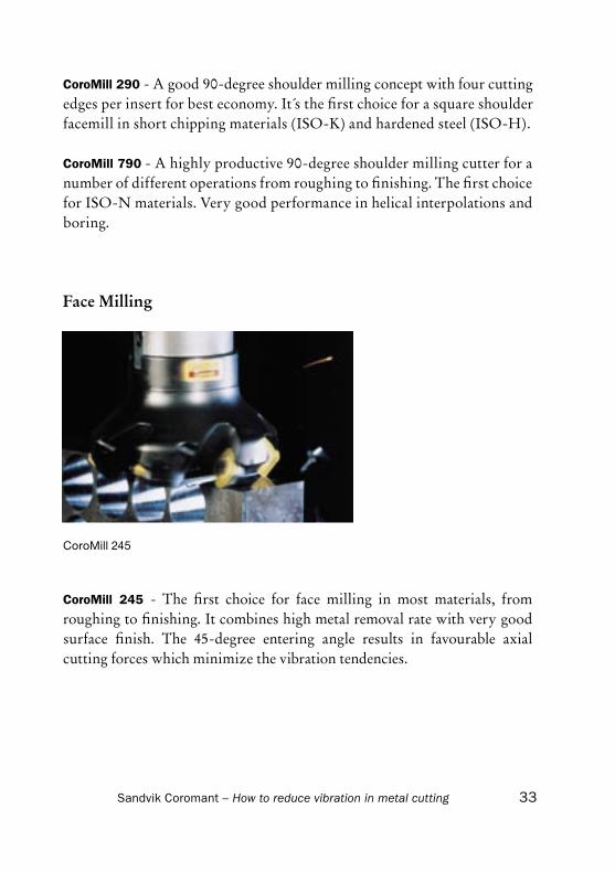
CoroMill 245
CoroMill 245 - The first choice for face milling in most materials, from roughing to finishing. It combines high metal removal rate with very good surface finish. The 45-degree entering angle results in favourable axial cutting forces which minimize the vibration tendencies.

Sandvik Coromant – How to reduce vibration in metal cutting34
CoroMill Century - A lightweight milling cutter concept for face and shoulder milling in ISO-N, ISO-H and ISO-K materials. It is perfect for high speed machining in non-ferrous materials. Balanced cutter body and axial adjustability of the insert contributes to a smooth, stable and vibration-free cutting action.
CoroMill 300 - A versatile and light cutting round insert concept for face milling, profiling, ramping and helical interpolation. High and vibra-tion-free metal removal with both short and long tools. Insert grades and geometries for all types of workpiece materials.
CoroMill 200 - A round insert concept for primarily roughing and difficult conditions. Is well suited to face milling and profiling. Cutter body designed with shim for best protection. Secure inserts with grades and geometries for best productivity in ISO-P, ISO-M and ISO-K applications.
CoroMill 210 - A very productive cutter concept, with four cutting edges per insert, for primarily roughing operations in most materials. Suited for a number of different operations where high metal removal rate is a priority. The first choice in rough machining involving high feed face milling, helical interpolation and plunge milling, with or without long tool overhang.
T-Max 45 - A heavy duty face milling concept for high metal removal in powerful milling machines or machining centres. The 45-degree entering angle and the strong insert allows the cutter to be used under tough and demanding conditions, including long overhangs.

Sandvik Coromant – How to reduce vibration in metal cutting 35
Profile Milling
CoroMill 216
CoroMill 216 - A robust ball endmill concept for roughing operations. Primarily general contouring and profiling. Also suitable for pocketing by ramping or helical interpolation. Insert grades and geometries for ISO-P, ISO-M and ISO-K applications.
CoroMill 216F - A ball nose concept for high speed finishing to super finishing of profiles. Possible to achieve a workpiece surface finish equal to what s possible with a solid carbide tool. Insert grades and geometries for all types of materials.
CoroMill Plura – A very versatile assortment of solid carbide endmills. Suitable for all type of operations, e.g profiling, shoulder milling, face milling, plunge milling and thread milling. Provides high productivity in all workpiece materials.
Sandvik Coromant – How to reduce vibration in metal cutting36
Slot Milling
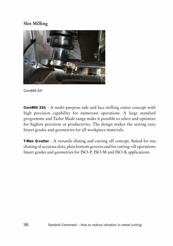
CoroMill 331
CoroMill 331 - A multi-purpose side and face milling cutter concept with high precision capability for numerous operations. A large standard programme and Tailor Made range make it possible to select and optimize for highest precision or productivity. The design makes the setting easy. Insert grades and geometries for all workpiece materials.
T-Max Q-cutter - A versatile slitting and cutting off concept. Suited for ma-chining of accurate slots, plain bottom grooves and for cutting-off operations. Insert grades and geometries for ISO-P, ISO-M and ISO-K applications.
Sandvik Coromant – How to reduce vibration in metal cutting 37
Operations – tool recommendations - some examples and
alternative applications
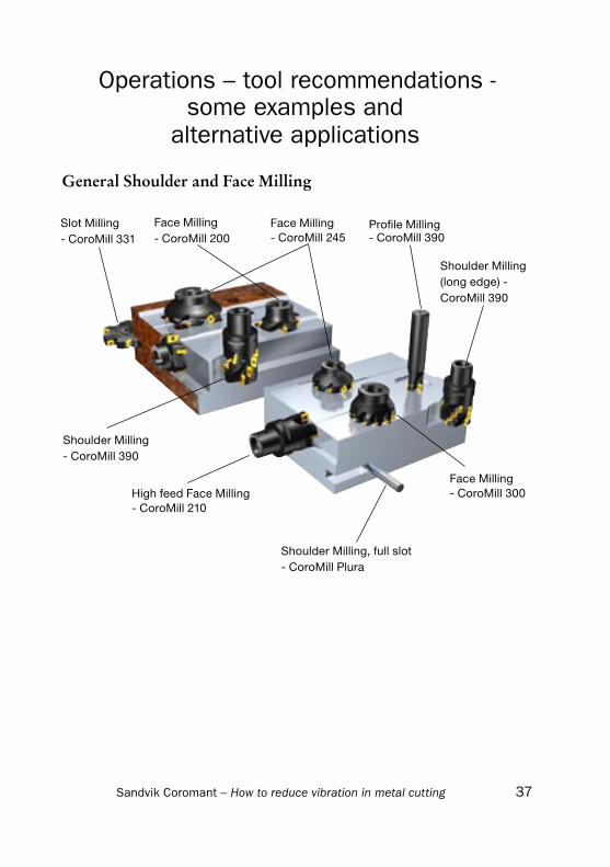
General Shoulder and Face Milling
Slot Milling- CoroMill 331
Face Milling - CoroMill 200
Face Milling- CoroMill 245
Profile Milling- CoroMill 390
Face Milling- CoroMill 300
Shoulder Milling - CoroMill 390
High feed Face Milling - CoroMill 210
Shoulder Milling, full slot - CoroMill Plura
Shoulder Milling (long edge) - CoroMill 390

Sandvik Coromant – How to reduce vibration in metal cutting38
General Profile Milling
Profile Milling, finishing- CoroMill 216F
High feed Face Milling- CoroMill 210
Profile Milling, helical interpolation- CoroMill 216
Profile Milling, ramping- CoroMill 390
Profile Milling, helical interpolation- CoroMill 300
Shoulder Milling, slot- CoroMill Plura
Face Milling- CoroMill 200
Profile Milling- CoroMill 300
Plunge Milling- CoroMill 210

Sandvik Coromant – How to reduce vibration in metal cutting 39
Aluminium machining, different operations
Profile Milling, pocketing- CoroMill 790
Face Milling- CoroMill Century
Slot Milling- CoroMill 331
Profile Milling, pocketing- CoroMill 390
Shoulder Milling, slot- CoroMill Plura

+ + - +
(+) + - -
(+) - - (+)
+ - - +
+ (-) (+) +
+ + + +
Sandvik Coromant – How to reduce vibration in metal cutting40
Clamping
One application within metal cutting that is very sensitive to vibration problems is milling with long overhang. The different tools for the applica-tion have various parameters that can be adjusted to suit the machine, the component and the material.In this chapter we will show some comparison between different holding systems.
Holding tools for rotatingCoupling comparison
BIG+
ISO
ABS
HSK
KM
Capto
Bendingstiffness
Torque Positioningand
repeatability
Run off

Sandvik Coromant – How to reduce vibration in metal cutting 41
Choice of holding tools• Use stiff modular tools with
good run-out accuracy• Modular tools increase the flexi-
bility and the possible number of combinations – use largest possible diameter on holding tools (extensions, adaptors) relative to cutter diameter
• For spindle speeds over 20,000 rpm use balanced cutting and holding tools
Long overhangsThe Coromant Capto® modular holding tool system allows combinations of long or short basic holders, extensions and reductions to an assembly of required length, with high stability and smallest run-out.
– maintain max productivity by choosing a series of extension modules for the roughing
cutter set-up– change extensions at pre-determined positions– adapt cutting data for each tool length– use damped, tapered bars for overhangs >4 - 5xD

Sandvik Coromant – How to reduce vibration in metal cutting42
CoroMill® cutters and holding tools with threaded coupling
CoroMillcutters
Intermediateadaptors
Basic holdersCoromant
Capto®
Solid carbide extension
Coromant Capto® ISO/MAS
HSK
210 390 300 216
HSK

Sandvik Coromant – How to reduce vibration in metal cutting 43
Hands on information
Insert geometry: Use sharp and positive inserts with a chip forming capacity.
Insert grade: Choose a small edge rounding (ER). Go from a thick coating to a thin one, if necessary use uncoated inserts.
Entering angle: The smaller the entering angle, the thinner the chip will be and the further it will spread along the cutting edge.
This will allow a higher feed per tooth. Also a smaller entering angle will direct more of the cutting force in axial direction and reduce the risk of vibration.

Sandvik Coromant – How to reduce vibration in metal cutting44
Tooth pitch:When machining with long tool over-hangs or unstable conditions, it will have a positive effect using a coarse pitch (L) cutter. Sometimes it can be a good idea to remove some of the inserts (e.g remove two inserts from a four inserts cutter).
Milling direction:Down milling is the first choice for most machining operations. In some cases, when the machine has insufficient power, the workpiece is very pliable, there is play in the table feed or vibrations arise during machining, up milling is the best choice. When up milling, remember that the cutting force tends to lift the workpiece up from the work table. This must be counteracted when clamping the workpiece.
Position/diameter:In general, when face milling, the cutter diameter should be 20-50% larger than the cutting width. The cutter should be positioned slightly off centre. Do not position the cutter dead centre.
When the cutter diameter is smaller than the workpiece, it is recommended that maximum width of cut is 60-70% of the cutter diameter.
In full slot milling, it is very important to reduce the number of inserts to avoid vibrations.

Sandvik Coromant – How to reduce vibration in metal cutting 45
Entry/exit:Avoid a situation where the centre-line or the cutter is in line with the work-piece edge. In this situation the insert is leaving cut when the chip thickness is at its maximum, with very high shock-loads at entry and exit.
Chip evacuation:Use compressed air to prevent recutting of the chips.
In deep cavity milling, this is especially important.
Notice that a coarse pitch (L) cutter will have more space to evacuate the chips.

Sandvik Coromant – How to reduce vibration in metal cutting46
Two axis ramping: One of the best methods to reach a full axial depth of cut is linear ramping in the X/Y and the Z axis.
If the correct starting point is chosen, there is no need for milling away stock from the ramping section.
Use compressed air to get the chips out of the cavity.
Milling strategy for opening a cavityThere are several ways to open a cavity. Three common methods can be the following:
Three axis ramping: Feeding the tool in a helical shaped path in the axial direction. It is recom-mended that the diameter of the hole is twice the diameter of the cutter.
Remember to check the maximum ramping angle for the cutter. Use com-pressed air to get the chips out of the cavity.

Sandvik Coromant – How to reduce vibration in metal cutting 47
Drilling/plunging:Pre-drilling followed by a plunge milling operation is a third option to open a cavity. This option requires an extra tool, more time for positio-ning and an extra position in the tool magazine. The positive advantage is that it is possible to machine with high axial feed.
Use compressed air to get the chips out of the cavity.
Milling in corners:Ensure that all programmed radii are 15% larger than the cutter diameter. Keep the same feed and speed in the corners.

Sandvik Coromant – How to reduce vibration in metal cutting48
Practical tips and hints on how to reduce vibrations
Boring
Adaptor Type and Size1. Choose the shortest possible adaptor. Every millimetre is important.2. Choose the largest possible diameter/size of the adaptor.3. For long overhang (>4xD) use damped adaptors, Silent Tools.4. If possible, use a tapered adaptor to increase the static stiffness and to
reduce the deflection.5. For long overhang, make sure to have a rigid clamping with flange con-
tact in the spindle.

Sandvik Coromant – How to reduce vibration in metal cutting 49
Insert1. Choose a light cutting insert with a positive cutting geometry. Knife-
edge inserts are first choice.2. Choose a small nose radius. For finish boring recommended nose radius
is 0.2 mm. Do not use larger nose radius than 0.4 mm. Try to choose a nose radius which is smaller than the depth of cut.
3. Use sharp inserts with relatively thin coatings. Try an uncoated insert. They will have a sharper cutting edge.
4. T-style inserts are first choice for boring operations.
Entering angle1. The entering angle should be close to 90 deg. This will give more axial
cutting forces and less radial/tangential forces.

Sandvik Coromant – How to reduce vibration in metal cutting50
Depth of cut1. Do not exceed half the cutting edge length when rough boring as this will
result in too high cutting forces on the cutting edge. When finish boring the maximum cutting depth is small. Typically less than 0.5 mm.
Tolerance of hole diameter1. For finishing with one insert, a tolerance of IT7 can be achieved under
good conditions.2. Tolerances will be influenced by the clamping of the tool holder, the
fixture of the component, wear of the inserts etc.3. It is recommended that a measuring cut is made to see what adjustment
is needed to compensate for tool deflection.4. To achieve a good surface finish and close tolerances it is important to
use cutting fluid. Cutting fluid will prevent recutting of chips and pre-vent heat expansion of the tool and workpiece.

Sandvik Coromant – How to reduce vibration in metal cutting 51
Select your tool system
For roughing and finishing in boring operations there are several options.
Boring tools for roughing:For roughing operations use Duobore with two inserts or CoroBore 820 with three inserts. For long overhang, beyond 4 x bar diameter, a damped Duobore adaptor is recommended.
Heavy duty roughing with cartridges and adjustable extension slides
Single edge boring with one insert
Twin edge boring with two inserts
Damped for deeper holes
Duobore for general boring
Productive boring with three inserts
Single edge boring with one insert Step boring

Sandvik Coromant – How to reduce vibration in metal cutting52
Boring tools for finishing:For finishing operations use a single edge fine boring tool or CoroBore 825 with one insert.
Single edge fine boring head with cartridge
Single edge fine boring head with boring bars for small diameters
Single edge fine boring head with cartridge and adjustable extension slide mounted on eccentric bar
Single edge fine boring head with cartridge and adjustable extension slide mounted on concentric bar
Damped single edge fine boring head with cartridge for deeper holes
830 reamer for high surface finish
Single edge fine boring head with cartridge mounted on adjustable extension slide

Sandvik Coromant – How to reduce vibration in metal cutting 53
Hands on information
Insert size:Do not use a a bigger insert size than necessary.
Nose radius:Use a small nose radius, 0.2 mm is recommended for finishing. A bigger nose radius will give larger radial forces.
Geometry:Use a sharp and positive geometry. A knife edge insert is a good alternative.
Insert style:Use a T-style insert and a 90 deg. entering angle.
Tool overhang:Always use as short as possible overhang. Machining with tool overhang (from insert tip to gauge line) more than 4 x the shank diameter, use a damped tool, Silent Tools.
Chip evacuation:Use cutting fluid to evacuate and to prevent recutting of the chips. Chips in the form of commas or determined spirals are the ideal.

a >a
1mm
1mm
Sandvik Coromant – How to reduce vibration in metal cutting54
Off centre boringIn some spindles it is possible to do off centre boring. It is important to remember that the centripetal force will increase and that too high spindle speed may give unstable conditions. Machining at long overhangs with damped tools the damping system can be taken out of function due to too high centripetal force. At Teeness.com it is possible to calculate the maximum spindle speed at a certain eccentric radius.
Step boringIn rough boring operations with two or more inserts, step boring is an effective way to increase the depth of cut without vibrations. The idea of step boring is to have the in-serts set to different radial and axial distance. To achieve different axial distance, shims have to be used.

Sandvik Coromant – How to reduce vibration in metal cutting 55
Silent ToolsSilent tools within milling
Coromant Capto:Shank with metric and inch pilot
Shank with threaded coupling
HSK:Shank with metric and inch pilot
Shank with threaded coupling
- For rough and fine boring operations beyond 4 x dia. tool overhang, it will be a big advantage to use Silent Tools.
- In milling applications, it is more difficult to give an exact overhang ratio when to change from solid tools to Silent Tools. For example will a 390 milling cutter (90 deg. entering angle) have more radial cutting forces than a 210 milling cutter (10 deg. entering angle), and the risk for vibra-tions to arise is higher. A damped tool might be necessary to maintain good productivity.

C-2920:23 ENG/01 Printed on recycled paper Printed in Sweden,
AB Sandvikens Tryckeri. © AB Sandvik Coromant 2006.01
Head office: AB Sandvik CoromantSE-811 81 Sandviken, Swedenwww.coromant.sandvik.com
Your Productivity Partner