how to size an ngr l xxen 2019 · 2019-05-13 · definitions savostianik: how to size an ngr...
TRANSCRIPT

EN
Guideline on How to Size an NGR
Knowledgebase Resistance-grounded power systems:Guideline on How to Size a Neutral-Grounding Resistor NGR(Neutral-Earthing Resistor NER)
Savostianik, P.ENG., Mervin
Savostianik: How to Size an NGR /2019.01

Bender GmbH & Co. KGP.O.Box 1161 • 35301 Gruenberg • GermanyLondorfer Straße 65 • 35305 Gruenberg • GermanyTel.: +49 6401 807-0 • Fax: +49 6401 807-259E-mail: [email protected] • www.bender.de
© Bender GmbH & Co. KGAll rights reserved.
Reprinting only with permissionof the publisher.
Subject to change!
Table of Contents
1. Definitions ................................................................................................................ 5
2. Selecting an NGR for a Wye-Connected Power Transformer or Generator . 6
2.1 Voltage Rating ........................................................................................................................... 6
2.2 Time Rating ................................................................................................................................ 7
2.3 Let-Through-Current Considerations (INGR) ................................................................. 7
2.4 Pulsing Ground-Fault-Location Method .......................................................................... 8
2.5 Standardization ........................................................................................................................ 9
3. Why Select an NGR Let-Through-Current Above Charging Current? ........... 9
3.1 Selective Coordination ........................................................................................................... 9
3.2 Detecting a High-Impedance Ground Fault ................................................................ 10
4. Harmonic Affects .................................................................................................. 10
5. NGR Monitoring .................................................................................................... 10
6. Summary ................................................................................................................ 11
3Savostianik: How to Size an NGR /2019.01
Table of Contents
4 Savostianik: How to Size an NGR /2019.01

Definitions
1. Definitions
What is… Definition
Alarm Indication, typically through visual or audible means, of the presence of an adverse condition such as a ground fault.
Bolted ground fault A zero-impedance connection of a system phase to ground.
Charging current Current that flows in a single phase-to-ground connection of an ungrounded power system.
Distributed system capacitanceThe line-to-ground capacitance formed by all energized conductors, in cables, transformers, motors, etc., that are separated from ground by insulation.
Ground A conductive material bonded to remote earth or the system ground connection. Defined as 0 V.
Ground-fault current (IGF)Electrical current that flows phase to ground at the point of fault. In a resistance-grounded system, ground-fault current is the sum of NGR current and charging current.
Ground-fault voltageThe voltage to ground that appears at the point of fault. It is the product of ground-fault current and ground-return-path impedance.
Ground leakage current (IGL)
Current that flows in the system neutral-to-ground connection in an energized un-faulted system. IGL is the result of unbalanced line-to-ground capacitances and unbalanced line-to-ground voltages. IGL is zero in an ideal, balanced, system.
Harmonic current
Non-linear loads such as adjustable-speed drives and rectifiers create voltages at frequencies that are multiples of the power-system fundamental frequency. These voltages drive harmonic-frequency current that should be considered when selecting an NGR, ground-fault sensing devices, and ground-fault-detection settings.
Neutral-grounding resistor (NGR) or neutral-earthing resistor (NER)
A purpose-made resistor connected between system neutral and ground (earth) with the purpose of limiting ground-fault current and ground-fault voltage. NGR’s are typically designed to meet the requirements of IEEE Standard 32 (and its replacement, IEEE PC57.32).
Selective coordination Automatic isolation (tripping) of faulted equipment while non-faulted equipment remains energized.
Transient overvoltage
In an ungrounded or inadequately grounded power system, an intermittent or rectified ground fault can periodically add charge to the system’s distributed capacitance, elevating all phases and neutral (if present) to a level that is several multiples of nominal system voltage above earth potential. This hazardous condition can cause difficult-to-diagnose equipment failures because of insulation breakdown.
TripDe-energize all or part of a power-distribution system upon the detection of an adverse condition such as a ground fault. This term can be applied to alarm-only systems.
5Savostianik: How to Size an NGR /2019.01
Selecting an NGR for a Wye-Connected Power Transformer or Generator
2. Selecting an NGR for a Wye-Connected Power Transformer or Generator
Aside from regulatory, environmental, and site considerations that affect the design of the resistor assembly, the key factors in selecting an NGR (NER) are the voltage rating, the time rating, and the let-through-current rating (INGR).
2.1 Voltage RatingAn NGR must be rated for system line-to-neutral voltage—the voltage across the resistor when a single-phase bolted ground fault is present.
Tripping ratio Multiple of NGR let-through-current rating to ground-fault-current detection setting.
Zero-sequence current transformer (ZSCT)
A window-type current transformer through which all current-carrying conductors pass, that measures zero-sequence (ground-fault) current by summing the currents in the monitored conductors. If this sum is not zero, the indicated current is flowing in another path—through ground.
The information contained herein equally applies to NGR’s connected to apower-distribution system through an artificial neutral, such as that establishedwith a zig-zag transformer.
When fault impedance is not zero, fault impedance is in series with NGRresistance, further limiting ground-fault current, and the voltage across thepoint of fault reduces NGR and neutral voltage.
While past practice has sometimes included a single-phase groundingtransformer to utilize a low-voltage resistor on a medium-voltage system,medium-voltage NGR’s for direct connection to system neutral are readilyavailable and are recommended as a simpler and more economic system-grounding solution, and for technical reasons outside the scope of this paper.
What is… Definition
6 Savostianik: How to Size an NGR /2019.01

Selecting an NGR for a Wye-Connected Power Transformer or Generator
2.2 Time RatingA resistance-grounded power-distribution system can be configured to trip, or to alarm, on the occurrence of a ground fault. An NGR dissipates P=I2R (or P=IV) power, in the form of heat, for the duration of a ground fault and must be able to do so, repeatedly, for its time rating.
For tripping systems, which rapidly de-energize a faulted circuit, a 10-second-rated NGR is typically recommended; 30- and 60-second variants are also available. For alarm-only systems (and hybrid systems that trip on a second-phase-to-ground fault), the NGR must have a continuous time rating.
2.3 Let-Through-Current Considerations (INGR)
Minimum Let-Through-Current for System Voltage Stability (INGR_min)To eliminate the possibility of a transient-overvoltage condition, the NGR let-through-current rating must be equal to or greater than system charging current.
System charging current can be conservatively estimated to be 0.5 A per MVA for low-voltage power-distribution systems and 1 A per MVA for medium-voltage systems. However, more-accurate estimates for existing or planned systems can be made using data tables that show charging current per unit length for cables, and for transformers, rotating machines, and capacitor banks.
For an existing system, charging current can be measured: De-energize the system supply transformer and open its neutral-to-ground connection. Connect a phase to ground through an appropriate ammeter (and a fuse). Energize the system and bring all loads on line. System charging current will be indicated by the ammeter. See Fig. 2.1 : System charging current changes when loads are switched and when the system size is changed by adding or removing lengths of cable.
Fig. 2.1 Charging Current Definition
When an NGR with the minimum INGR_min current rating is used, ground-fault location and selective coordination are difficult to achieve. In a multi-feeder system with a ground fault present, a zero-sequence current transformer (ZSCT) (or a clip-on ammeter) monitoring a non-faulted feeder will indicate the charging current of that feeder, while a ZSCT on the faulted feeder detects the vector
Continuous-time rated NGR’s can be used on tripping systems, but they typicallyhave a higher price and can be physically larger.
B
N A
C
ACBG CAG
NeutralDisconnected
NGR
GINGR = 0
IX_BG
IX_AG ICharge
Feeders&
Loads
Distributed System CapacitanceShown as Lumped Capacitors
7Savostianik: How to Size an NGR /2019.01
Selecting an NGR for a Wye-Connected Power Transformer or Generator
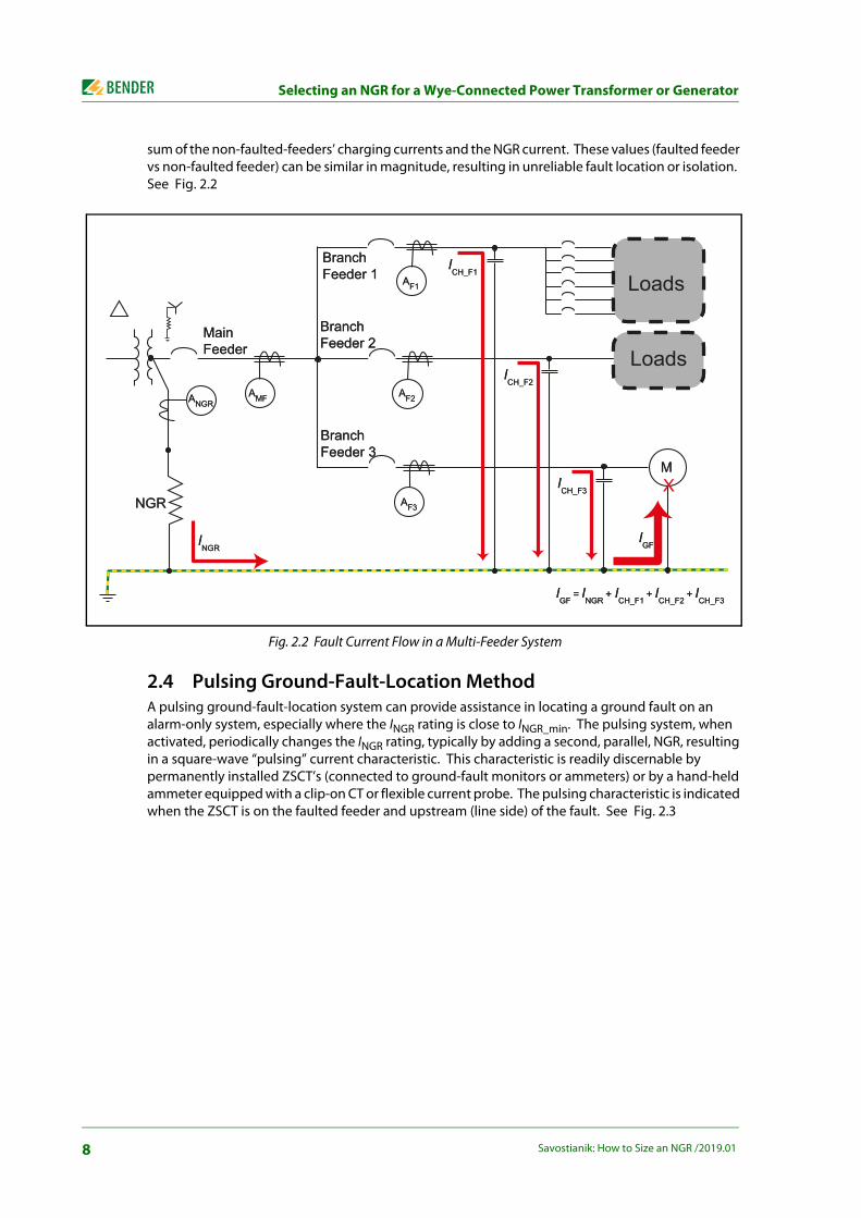
sum of the non-faulted-feeders’ charging currents and the NGR current. These values (faulted feeder vs non-faulted feeder) can be similar in magnitude, resulting in unreliable fault location or isolation. See Fig. 2.2
Fig. 2.2 Fault Current Flow in a Multi-Feeder System
2.4 Pulsing Ground-Fault-Location MethodA pulsing ground-fault-location system can provide assistance in locating a ground fault on an alarm-only system, especially where the INGR rating is close to INGR_min. The pulsing system, when activated, periodically changes the INGR rating, typically by adding a second, parallel, NGR, resulting in a square-wave “pulsing” current characteristic. This characteristic is readily discernable by permanently installed ZSCT’s (connected to ground-fault monitors or ammeters) or by a hand-held ammeter equipped with a clip-on CT or flexible current probe. The pulsing characteristic is indicated when the ZSCT is on the faulted feeder and upstream (line side) of the fault. See Fig. 2.3
XM
ANGRAMF
Main Feeder
BranchFeeder 1
BranchFeeder 2
BranchFeeder 3
AF1
AF2
AF3
Loads
Loads
NGR
ICH_F1
ICH_F2
ICH_F3
INGR
IGF
IGF
= INGR
+ ICH_F1
+ ICH_F2
+ ICH_F3
M
ANGRAMF
Main Feeder
BranchFeeder 1
BranchFeeder 2
BranchFeeder 3
AF1
AF2
AF3
Loads
Loads
NGR
ICH_F1
ICH_F2
ICH_F3
INGR
IGF
IGF
= INGR
+ ICH_F1
+ ICH_F2
+ ICH_F3
8 Savostianik: How to Size an NGR /2019.01

Why Select an NGR Let-Through-Current Above Charging Current?
.
Fig. 2.3 Pulsing Ground-Fault Location System
2.5 StandardizationNGR suppliers may have a standard-product line of more-common items, such as 2- or 5-A 480- and 600-V resistors in standard-size and -material NEMA 3R enclosures. These items often have shorter lead times and a lower price than a custom design. Where NGR certification is required, a custom design may incur prohibitive cost and time delay.
3. Why Select an NGR Let-Through-Current Above Charging Current?
3.1 Selective CoordinationFor tripping systems in which it is desired to isolate faulted equipment while allowing the rest of the system to remain energized, ground-fault protection at the feeder or load level can detect the fault and automatically open the associated circuit breaker, contactor, or motor starter to isolate the faulted circuit. The ground-fault monitor typically uses a ZSCT as a sensor, and can be a stand-alone unit, a multi-feeder ground-fault monitor, or integrated into a multi-function feeder- or motor-protection relay. A power-distribution system can use a combination of these devices.
To ensure that a ground-fault relay does not nuisance trip or false alarm when an upstream ground fault (such as on a different feeder) occurs, choose a ground-fault-monitor trip setting that is higher than the monitored load’s charging current. A useful guideline is to choose this setting to be above the largest-feeder charging current, for all devices.
M
ANGRAMF
Main Feeder
BranchFeeder 1
BranchFeeder 2
BranchFeeder 3
AF1
AF2
AF3
Loads
LoadsICH_F1
ICH_F2
ICH_F3
INGR
IGF
IGF
= INGR
+ ICH_F1
+ ICH_F2
+ ICH_F3
Xt
9Savostianik: How to Size an NGR /2019.01

Harmonic Affects
3.2 Detecting a High-Impedance Ground FaultNot all ground faults are bolted faults. Fault impedance in series with NGR resistance can limit IGF to a value that is lower than the ground-fault-monitor detection setting, especially when INGR is near INGR_min. Ground-fault current below the detection setting will not be detected.
To illustrate; a ground fault at a motor terminal can be a bolted fault and result in the expected ground-fault current. However, a ground fault in the motor winding will be subject to motor-winding impedance, further limiting IGF. To detect a ground fault in 80 % of a machine winding, the ground-fault-monitor detection setting must be no more than 20 % of INGR, which requires INGR to be at least five times the ground-fault detection setting. This is a tripping ratio of 5.
An adequate tripping ratio simultaneously provides ease of ground-fault location, selective coordination, and the ability to detect a high-impedance ground fault. A minimum tripping ratio is required by some codes and standards1).
4. Harmonic AffectsThe operation of non-linear loads in a power system creates harmonic line-to-ground voltages. Because capacitive reactance is inversely proportional to frequency (XC = ½ πfC), current per unit voltage is higher at higher frequencies. This can be an important consideration for the selection of a ground-fault monitor and its detection setting, for NGR let-through-current selection—charging current will be higher, and for the NGR time rating—ground-leakage current will be higher than it would be for a system with only power-frequency loads.
Ground-fault detection devices have a frequency response determined by their design—choose devices that are appropriate for the monitored system. In a system with possible high harmonic content, it is prudent to use at least one device, installed to monitor system neutral current, that is capable of detecting a non-fundamental-frequency ground fault.
5. NGR MonitoringA grounded system uses zero-sequence-current monitoring to detect ground faults.
An NGR is a resistor that dissipates I2R heat for the duration of a ground fault, as well as the heat that results from ground-leakage current whenever the system is operating. Thermally induced mechanical stresses along with the possible presence of corrosive atmospheres (salt, H2S) and high humidity can lead to NGR failure. NGR enclosures are typically ventilated to allow convective cooling, and are often located outdoors, allowing the ingress of wind-blown dust, rain, and snow. Mechanical vibration and wildlife (rodents, snakes, birds) are also known causes of NGR failure.
An open NGR leaves the power system ungrounded—no zero-sequence current will flow when a ground fault occurs and it will remain undetected unless remedial measures are used. To mitigate this possibility, continuous NGR monitoring should be included in every NGR application.
A properly designed NGR monitor will detect NGR failure in an energized or de-energized system, with or without a ground fault present; it will detect a ground fault with or without a healthy NGR in the system, providing backup or primary ground-fault detection; and it will alarm or trip the system as necessary.
10 Savostianik: How to Size an NGR /2019.01

Summary
6. SummaryNGR Voltage Rating Choose system line-to-neutral voltage.
NGR Time Rating Choose a short time rating for tripping systems2) and a continuous time rating for alarm-only systems.
NGR Current Rating Choose a value at least equal to system charging current. For selective coordination, ease of fault location, and high-impedance fault detection, choose a ground-fault-detection setting above the largest-feeder charging current and use a tripping ratio of 5 or more (INGR = Isetting x 5).
NGR Monitor Always use an NGR monitor2).
1) Examples include CSA M421 Use of electricity in mines and AS/NZS 2081 Electrical protection devices for mines and quarries.
2) IEEE Standard PC57.32 recommends continuous monitoring of non-continuous-duty NGR’s.
11Savostianik: How to Size an NGR /2019.01

Bender GmbH & Co. KGP.O.Box 1161 • 35301 Gruenberg • GermanyLondorfer Straße 65 • 35305 Gruenberg • GermanyTel.: +49 6401 807-0 • Fax: +49 6401 807-259E-mail: [email protected] • www.bender.de
BENDER Group