how to use nrpz instrument drivers · for 32-bit version of labview: - download and install...
TRANSCRIPT
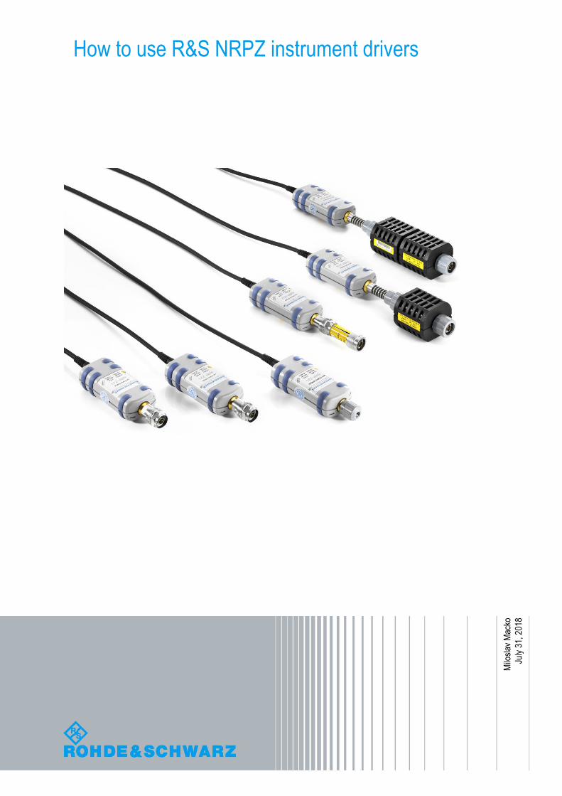
How to use R&S NRPZ instrument drivers
Milo
slav
Mac
ko
July
31,
201
8
Table of Contents
NRP-Z Powersensors system drivers installation ............................ 3
Power Viewer ....................................................................................... 4
NRP-Z Powersensors instrument drivers installation ...................... 5
LabVIEW instrument driver ........................................................................................ 6
LabWindows/CVI instrument driver .......................................................................... 6
VXIplug&play instrument driver ................................................................................ 7
Usage of NRP-Z Powersensor instrument drivers ........................... 8
Instrument driver structure ........................................................................................ 8
Powersensor connection initialization ..................................................................... 8
Resource name string examples: ............................................................................ 10
Working with more than 1 powersensor ................................................................. 11
One session, powersensors addressed by channel parameter ........................... 11
Unique session for each powersensor ................................................................... 12
Examples.................................................................................................................... 13
Simple non-triggered average mode ....................................................................... 13
Externally triggered average mode ......................................................................... 14
Internally triggered average mode .......................................................................... 14
Internally triggered timeslot mode .......................................................................... 15
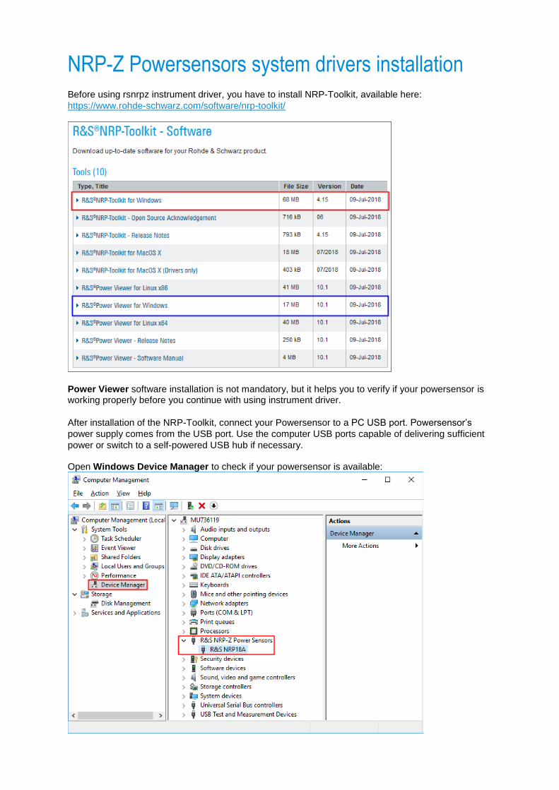
NRP-Z Powersensors system drivers installation Before using rsnrpz instrument driver, you have to install NRP-Toolkit, available here:
https://www.rohde-schwarz.com/software/nrp-toolkit/
Power Viewer software installation is not mandatory, but it helps you to verify if your powersensor is working properly before you continue with using instrument driver.
After installation of the NRP-Toolkit, connect your Powersensor to a PC USB port. Powersensor’s
power supply comes from the USB port. Use the computer USB ports capable of delivering sufficient
power or switch to a self-powered USB hub if necessary. Open Windows Device Manager to check if your powersensor is available:
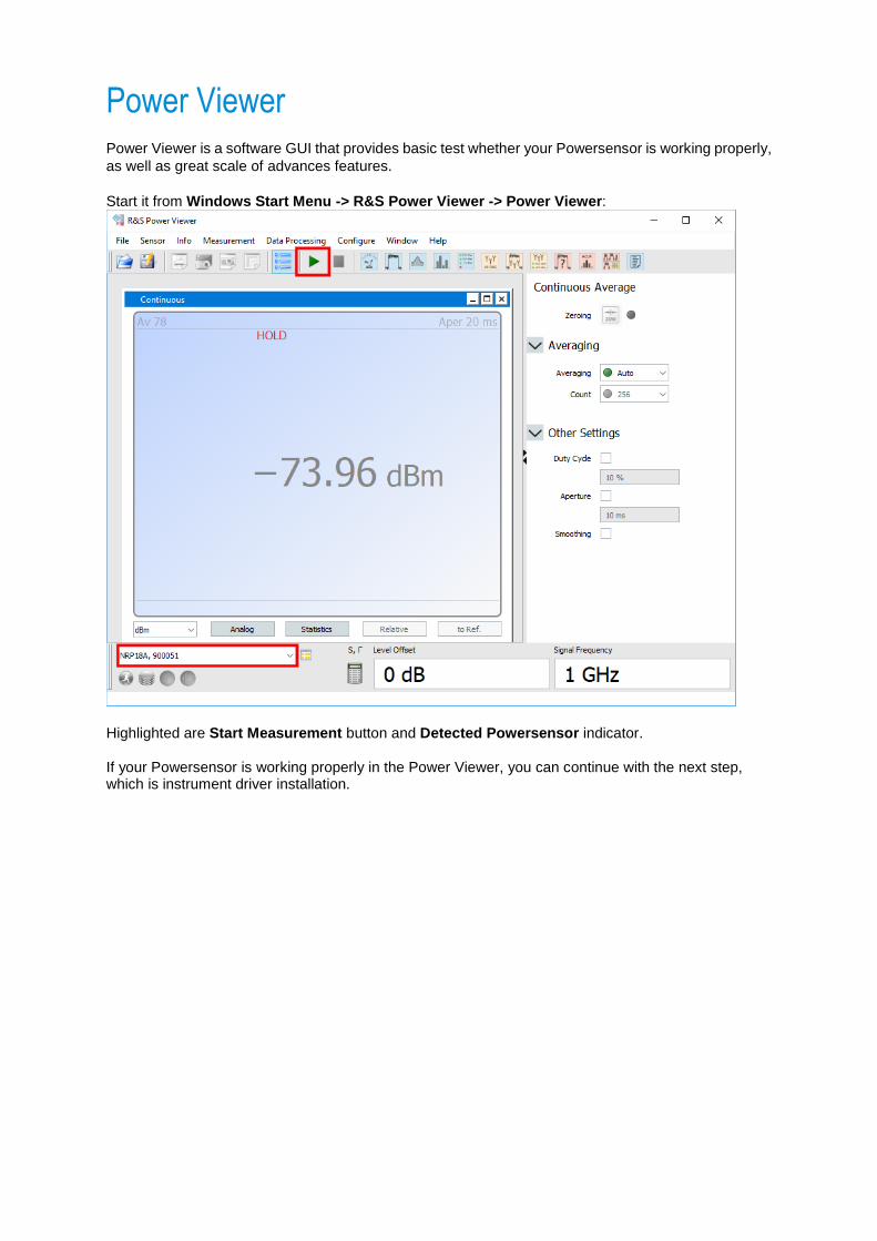
Power Viewer Power Viewer is a software GUI that provides basic test whether your Powersensor is working properly,
as well as great scale of advances features.
Start it from Windows Start Menu -> R&S Power Viewer -> Power Viewer:
Highlighted are Start Measurement button and Detected Powersensor indicator. If your Powersensor is working properly in the Power Viewer, you can continue with the next step, which is instrument driver installation.
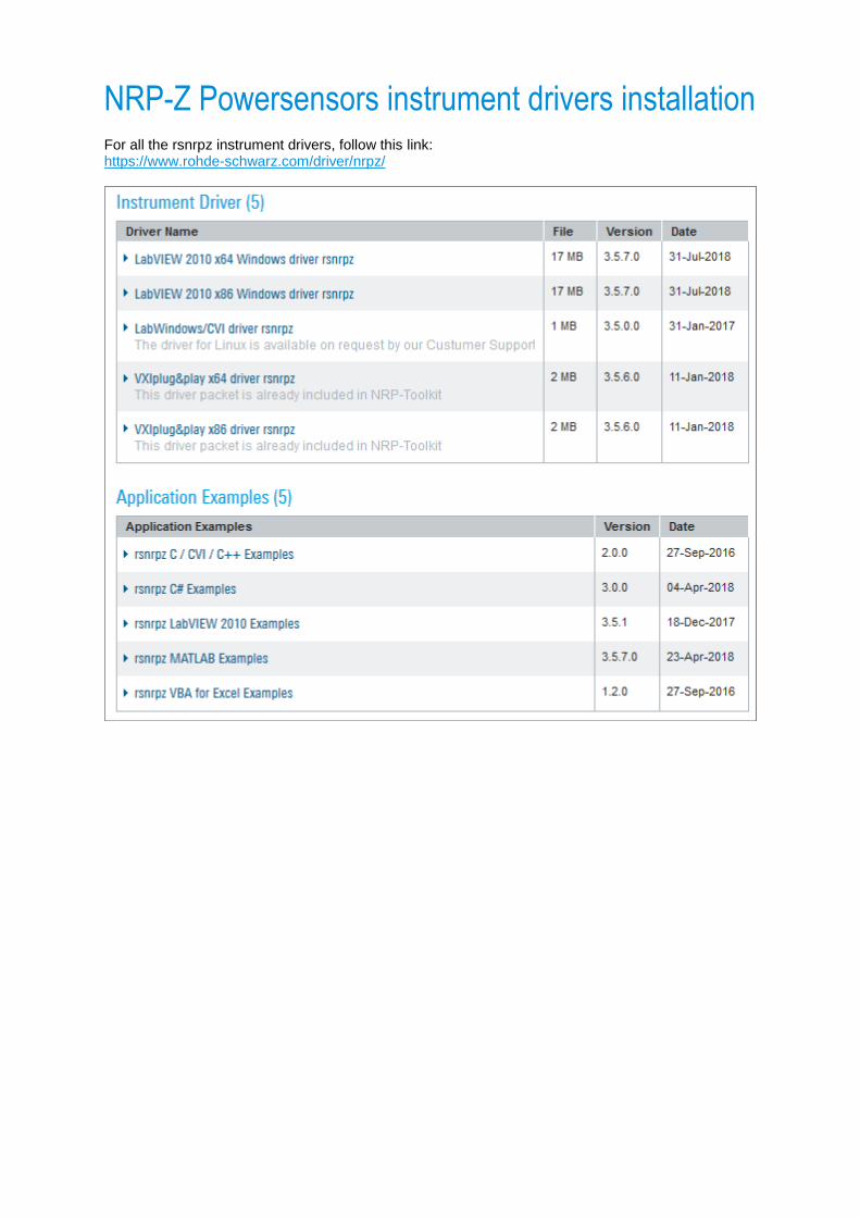
NRP-Z Powersensors instrument drivers installation For all the rsnrpz instrument drivers, follow this link: https://www.rohde-schwarz.com/driver/nrpz/
LabVIEW instrument driver
You need LabVIEW 2010 or higher to use the R&S rsnrpz LabVIEW driver. Since the LabVIEW driver is only a wrapper over VXIplug&play driver, you need to install the VXIplug&play driver beforehand. For 64-bit version of LabVIEW:
- Download and install VXIplug&play x64 driver rsnrpz - Download and install LabVIEW 2010 x64 Windows driver rsnrpz
For 32-bit version of LabVIEW:
- Download and install VXIplug&play x86 driver rsnrpz - Download and install LabVIEW 2010 x86 Windows driver rsnrpz
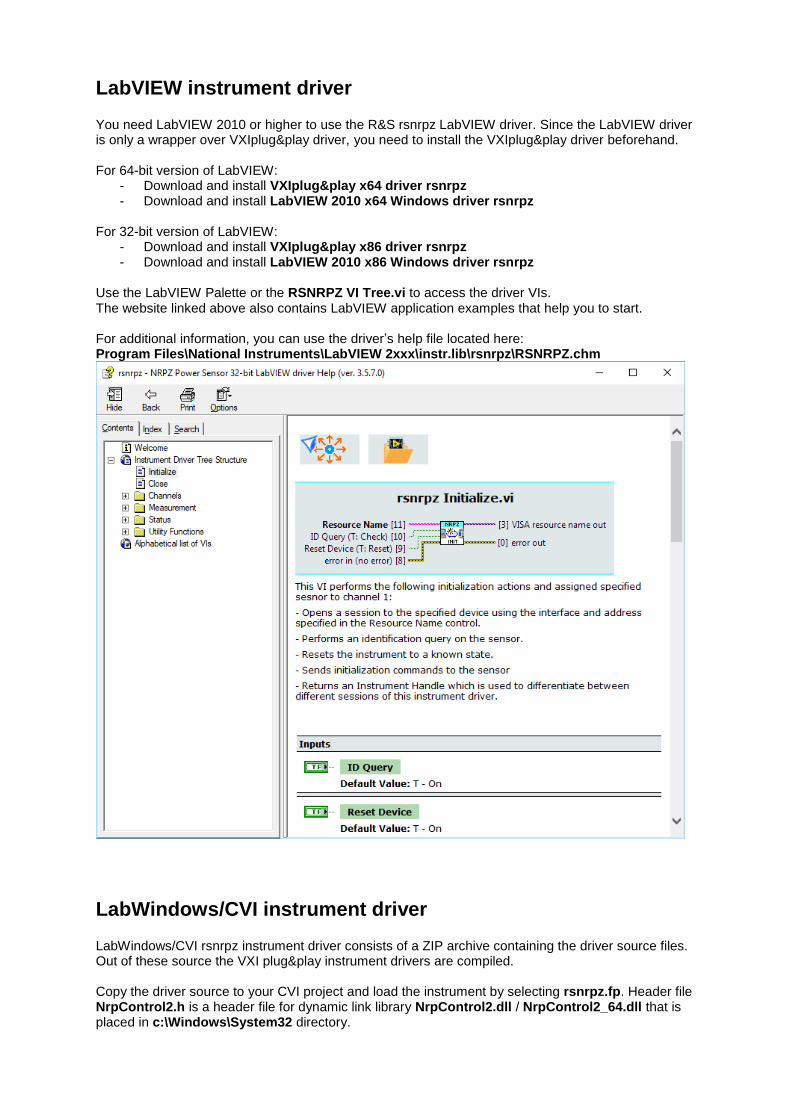
Use the LabVIEW Palette or the RSNRPZ VI Tree.vi to access the driver VIs. The website linked above also contains LabVIEW application examples that help you to start. For additional information, you can use the driver’s help file located here: Program Files\National Instruments\LabVIEW 2xxx\instr.lib\rsnrpz\RSNRPZ.chm
LabWindows/CVI instrument driver
LabWindows/CVI rsnrpz instrument driver consists of a ZIP archive containing the driver source files. Out of these source the VXI plug&play instrument drivers are compiled. Copy the driver source to your CVI project and load the instrument by selecting rsnrpz.fp. Header file NrpControl2.h is a header file for dynamic link library NrpControl2.dll / NrpControl2_64.dll that is placed in c:\Windows\System32 directory.
VXIplug&play instrument driver
This driver is the most universal and can be used in all environments that support calling dynamic or
static link library functions.
Paths described in this chapter are default installation paths using Windows 10 64-bit version. For
Windows 32-bit version use Program Files instead of Program Files (x86) directory.
64-bit VXIplug&play driver: Additional driver files directory: c:\Program Files\IVI Foundation\VISA\Win64\rsnrpz Help file: c:\Program Files\IVI Foundation\VISA\Win64\rsnrpz\rsnrpz_vxi.chm Driver DLL: c:\Program Files\IVI Foundation\VISA\Win64\Bin\rsnrpz_64.dll Driver LLB: c:\Program Files\IVI Foundation\VISA\Win64\Lib_x64\msc\rsnrpz_64.lib Header file: c:\Program Files\IVI Foundation\VISA\Win64\include\rsnrpz.h C# wrapper: c:\Program Files\IVI Foundation\VISA\Win64\include\rsnrpz64.cs Visual Basic .NET wrapper: c:\Program Files\IVI Foundation\VISA\Win64\include\rsnrpz64.vb
32-bit VXIplug&play driver: Additional driver files directory: c:\Program Files (x86)\IVI Foundation\VISA\WinNT\rsnrpz Help file: c:\Program Files (x86)\IVI Foundation\VISA\WinNT\rsnrpz\rsnrpz_vxi.chm Driver DLL: c:\Program Files (x86)\IVI Foundation\VISA\WinNT\Bin\rsnrpz_32.dll Driver LLB: c:\Program Files (x86)\IVI Foundation\VISA\WinNT\lib\msc\rsnrpz_32.lib Header file: c:\Program Files (x86)\IVI Foundation\VISA\WinNT\include\rsnrpz.h C# wrapper: c:\Program Files (x86)\IVI Foundation\VISA\WinNT\include\rsnrpz.cs Visual Basic .NET wrapper: c:\Program Files (x86)\IVI Foundation\VISA\WinNT\include\rsnrpz.vb
Usage of NRP-Z Powersensor instrument drivers The instrument driver link https://www.rohde-schwarz.com/driver/nrpz/ contains application examples,
which you can download to getting started.
Instrument driver structure
Here, we only explain VXIplug&play driver usage. Since the VXIplug&play driver is a compiled
LabWindows/CVI driver, they have the same API. For LabVIEW, the dll-wrapper VI names are
different from dll-function names. For example, the function rsnrpz_init() is in LabVIEW
represented by RSNRPZ Initialize.vi. However, the structure of both instrument drivers is the
same. To find the corresponding function, refer to help files rsnrpz_vxi.chm (CVI and VXIpnp) and
RSNRPZ.chm (LabVIEW).
For backwards compatibility, the following functions are still available, although we do not recommend
using them anymore:
rsnrpz_AddSensor / RSNRPZ Add Sensor.vi
rsnrpz_CloseSensor / RSNRPZ Close Sensor.vi
Powersensor connection initialization
Usage of the instrument driver always starts with Initializing of one or more powersensors.
Function prototype:
ViStatus rsnrpz_init (ViRsrc resourceName, ViBoolean idQuery,
ViBoolean resetDevice, ViSession* instrumentHandle);
resourceName is a string with the following format:
USB::<VendorID>::<ProductID>::<SerialNumber>
VendorID is 0xAAD for all Rohde & Schwarz instrument.
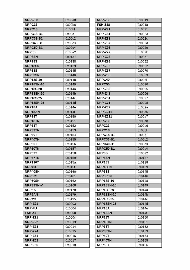
ProductID depends on powersensor model:
Powersensor model ProductID
NRP-Z21 0x0003
NRP-FU 0x0004
FSH-Z1 0x000b
NRP-Z11 0x000c
NRP-Z22 0x0013
NRP-Z23 0x0014
NRP-Z24 0x0015
NRP-Z51 0x0016
NRP-Z52 0x0017
NRP-Z55 0x0018
NRP-Z56 0x0019
FSH-Z18 0x001a
NRP-Z91 0x0021
NRP-Z81 0x0023
NRP-Z31 0x002c
NRP-Z37 0x002d
NRP-Z96 0x002e
NRP-Z27 0x002f
NRP-Z28 0x0051
NRP-Z98 0x0052
NRP-Z92 0x0062
NRP-Z57 0x0070
NRP-Z85 0x0083
NRPC40 0x008f
NRPC50 0x0090
NRP-Z86 0x0095
NRP-Z41 0x0096
NRP-Z61 0x0097
NRP-Z71 0x0098
NRP-Z32 0x009a
NRP-Z211 0x00a6
NRP-Z221 0x00a7
NRP-Z58 0x00a8
NRPC33 0x00b6
NRPC18 0x00bf
NRPC18-B1 0x00c1
NRPC33-B1 0x00c2
NRPC40-B1 0x00c3
NRPC50-B1 0x00c4
NRP8S 0x00e2
NRP8SN 0x0137
NRP18S 0x0138
NRP18SN 0x0139
NRP33S 0x0145
NRP33SN 0x0146
NRP18S-10 0x0148
NRP18SN-10 0x0149
NRP18S-20 0x014a
NRP18SN-20 0x014b
NRP18S-25 0x014c
NRP18SN-25 0x014d
NRP18A 0x014e
NRP18AN 0x014f
NRP18T 0x0150
NRP18TN 0x0151
NRP33T 0x0152
NRP33TN 0x0153
NRP40T 0x0154
NRP40TN 0x0155
NRP50T 0x0156
NRP50TN 0x0157
NRP67T 0x0158
NRP67TN 0x0159
NRP110T 0x015a
NRP40S 0x015f
NRP40SN 0x0160
NRP50S 0x0161
NRP50SN 0x0162
NRP33SN-V 0x0168
NRP6A 0x0178
NRP6AN 0x0179
NRPM3 0x0195
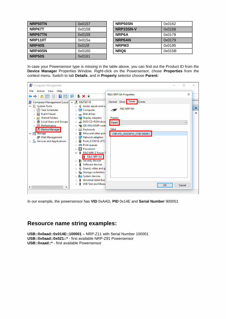
NRQ6 0x015B
In case your Powersensor type is missing in the table above, you can find out the Product ID from the
Device Manager Properties Window. Right-click on the Powersensor, chose Properties from the
context menu. Switch to tab Details, and in Property selector choose Parent:
In our example, the powersensor has VID 0xAAD, PID 0x14E and Serial Number 900051
Resource name string examples:
USB::0x0aad::0x014E::100001 – NRP-Z11 with Serial Number 100001
USB::0x0aad::0x021::* - first available NRP-Z91 Powersensor
USB::0xaad::* - first available Powersensor
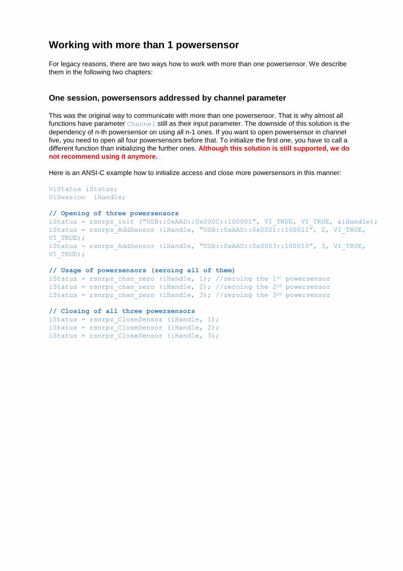
Working with more than 1 powersensor
For legacy reasons, there are two ways how to work with more than one powersensor. We describe
them in the following two chapters:
One session, powersensors addressed by channel parameter
This was the original way to communicate with more than one powersensor. That is why almost all
functions have parameter Channel still as their input parameter. The downside of this solution is the
dependency of n-th powersensor on using all n-1 ones. If you want to open powersensor in channel
five, you need to open all four powersensors before that. To initialize the first one, you have to call a
different function than initializing the further ones. Although this solution is still supported, we do
not recommend using it anymore.
Here is an ANSI-C example how to initialize access and close more powersensors in this manner:
ViStatus iStatus;
ViSession iHandle;
// Opening of three powersensors
iStatus = rsnrpz_init (“USB::0xAAD::0x000C::100001”, VI_TRUE, VI_TRUE, &iHandle);
iStatus = rsnrpz_AddSensor (iHandle, “USB::0xAAD::0x0021::100011”, 2, VI_TRUE,
VI_TRUE);
iStatus = rsnrpz_AddSensor (iHandle, “USB::0xAAD::0x0003::100010”, 3, VI_TRUE,
VI_TRUE);
// Usage of powersensors (zeroing all of them)
iStatus = rsnrpz_chan_zero (iHandle, 1); //zeroing the 1st powersensor
iStatus = rsnrpz_chan_zero (iHandle, 2); //zeroing the 2nd powersensor
iStatus = rsnrpz_chan_zero (iHandle, 3); //zeroing the 3rd powersensor
// Closing of all three powersensors
iStatus = rsnrpz_CloseSensor (iHandle, 1);
iStatus = rsnrpz_CloseSensor (iHandle, 2);
iStatus = rsnrpz_CloseSensor (iHandle, 3);

Unique session for each powersensor
With this approach, every powersensor has its unique handle that are independent. The parameter
Channel is always set to 1 (in LabVIEW not connected). This is the recommended way of working
with more than one powersensor
Same example as in previous chapter using unique sessions approach:
ViStatus iStatus;
ViSession iHandle1, iHandle2, iHandle3;
// Opening of three powersensors
iStatus = rsnrpz_init (“USB::0xAAD::0x000C::100001”, VI_TRUE, VI_TRUE, &iHandle1);
iStatus = rsnrpz_init (“USB::0xAAD::0x0021::100011”, VI_TRUE, VI_TRUE, &iHandle2);
iStatus = rsnrpz_init (“USB::0xAAD::0x0003::100010”, VI_TRUE, VI_TRUE, &iHandle3);
// Usage of powersensors (zeroing all of them)
iStatus = rsnrpz_chan_zero (iHandle1, 1); //zeroing the 1st powersensor
iStatus = rsnrpz_chan_zero (iHandle2, 1); //zeroing the 2nd powersensor
iStatus = rsnrpz_chan_zero (iHandle3, 1); //zeroing the 3rd powersensor
// Closing of all three powersensors
iStatus = rsnrpz_Close (iHandle1); //or iStatus = rsnrpz_CloseSensor (iHandle1, 1);
iStatus = rsnrpz_Close (iHandle2); //or iStatus = rsnrpz_CloseSensor (iHandle2, 1);
iStatus = rsnrpz_Close (iHandle3); //or iStatus = rsnrpz_CloseSensor (iHandle3, 1);
Notice that the function rsnrpz_Close closes all channels if more than one exist, while
rsnrpz_CloseSensor only closes the specified channel. For only one powersensor per session,
both functions have the same effect.
Examples
All examples are written in LabWindows/CVI with the intention to give user a template about steps
and the order of function calls to perform similar measurement tasks in his own programming
language. Use the examples from the instrument driver’s website as project templates to insert the
following code into.
Simple non-triggered average mode
In this mode, the powersensor measures immediately for defined time (set by
rsnrpz_avg_configureAvgManual) and returns the result:
ViSession iHandle;
ViBoolean meas_complete = VI_FALSE;
ViReal64 dResultArray[1];
ViReal dMeasValue = 0.0;
ViInt32 iReadCount;
// Initialization
rsnrpz_init (”USB::0x0aad::0x0021::100001”, 1, 1, & iHandle);
// Configuration of the measurement
rsnrpz_chan_mode (iHandle, 1, 0); //continue average mode
rsnrpz_chan_setCorrectionFrequency (iHandle, 1, 1E9)); //setting corr.
frequency to 1GHz
rsnrpz_trigger_setSource (iHandle, 1, 3); //immediate trigger
rsnrpz_avg_configureAvgManual (iHandle, 1, 5); //manual averaging of 5
values
// Measurement – this section can be repeated to get more measurements
rsnrpz_chans_initiate (iHandle); //start the measurement – from this moment
instrument reacts on trigger event. In case of immediate trigger, it starts
measuring immediately
// Waiting for measurement to finish
do
{
rsnrpz_chan_isMeasurementComplete(io, 1, &meas_complete)); //check if
measurement is complete
Delay (0.1); //wait 100ms
} while (meas_complete == VI_FALSE); //wait until measurement is
completed. Include timeout for this loop to prevent deadlock
rsnrpz_meass_fetchBufferMeasurement(io, 1, 1, &dResultArray, &iReadCount);
dMeasValue = dResultArray[0];
Alternatively, for the //Measurement section the following code is functionally identical (see the
difference between functions: rsnrpz_meass_readBufferMeasurement
and rsnrpz_meass_fetchBufferMeasurement
rsnrpz_meass_readBufferMeasurement (iHandle, 1, 5000, 1, &dResultArray,
&iReadCount); // Initialize the measurement with timeout of 5000ms, wait
for measurement to finish and read the result
dMeasValue = dResultArray[0];
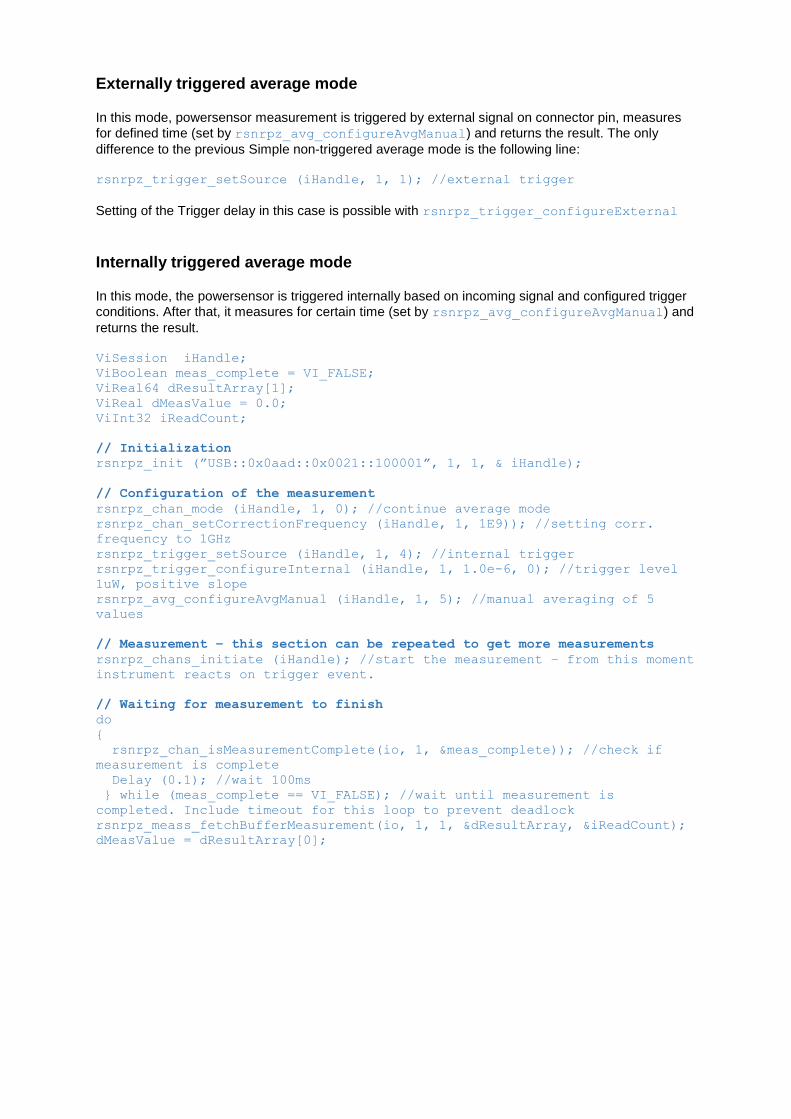
Externally triggered average mode
In this mode, powersensor measurement is triggered by external signal on connector pin, measures
for defined time (set by rsnrpz_avg_configureAvgManual) and returns the result. The only
difference to the previous Simple non-triggered average mode is the following line: rsnrpz_trigger_setSource (iHandle, 1, 1); //external trigger
Setting of the Trigger delay in this case is possible with rsnrpz_trigger_configureExternal
Internally triggered average mode
In this mode, the powersensor is triggered internally based on incoming signal and configured trigger
conditions. After that, it measures for certain time (set by rsnrpz_avg_configureAvgManual) and
returns the result. ViSession iHandle;
ViBoolean meas_complete = VI_FALSE;
ViReal64 dResultArray[1];
ViReal dMeasValue = 0.0;
ViInt32 iReadCount;
// Initialization
rsnrpz_init (”USB::0x0aad::0x0021::100001”, 1, 1, & iHandle);
// Configuration of the measurement
rsnrpz_chan_mode (iHandle, 1, 0); //continue average mode
rsnrpz_chan_setCorrectionFrequency (iHandle, 1, 1E9)); //setting corr.
frequency to 1GHz
rsnrpz_trigger_setSource (iHandle, 1, 4); //internal trigger
rsnrpz_trigger_configureInternal (iHandle, 1, 1.0e-6, 0); //trigger level
1uW, positive slope
rsnrpz_avg_configureAvgManual (iHandle, 1, 5); //manual averaging of 5
values
// Measurement – this section can be repeated to get more measurements
rsnrpz_chans_initiate (iHandle); //start the measurement – from this moment
instrument reacts on trigger event.
// Waiting for measurement to finish
do
{
rsnrpz_chan_isMeasurementComplete(io, 1, &meas_complete)); //check if
measurement is complete
Delay (0.1); //wait 100ms
} while (meas_complete == VI_FALSE); //wait until measurement is
completed. Include timeout for this loop to prevent deadlock
rsnrpz_meass_fetchBufferMeasurement(io, 1, 1, &dResultArray, &iReadCount);
dMeasValue = dResultArray[0];
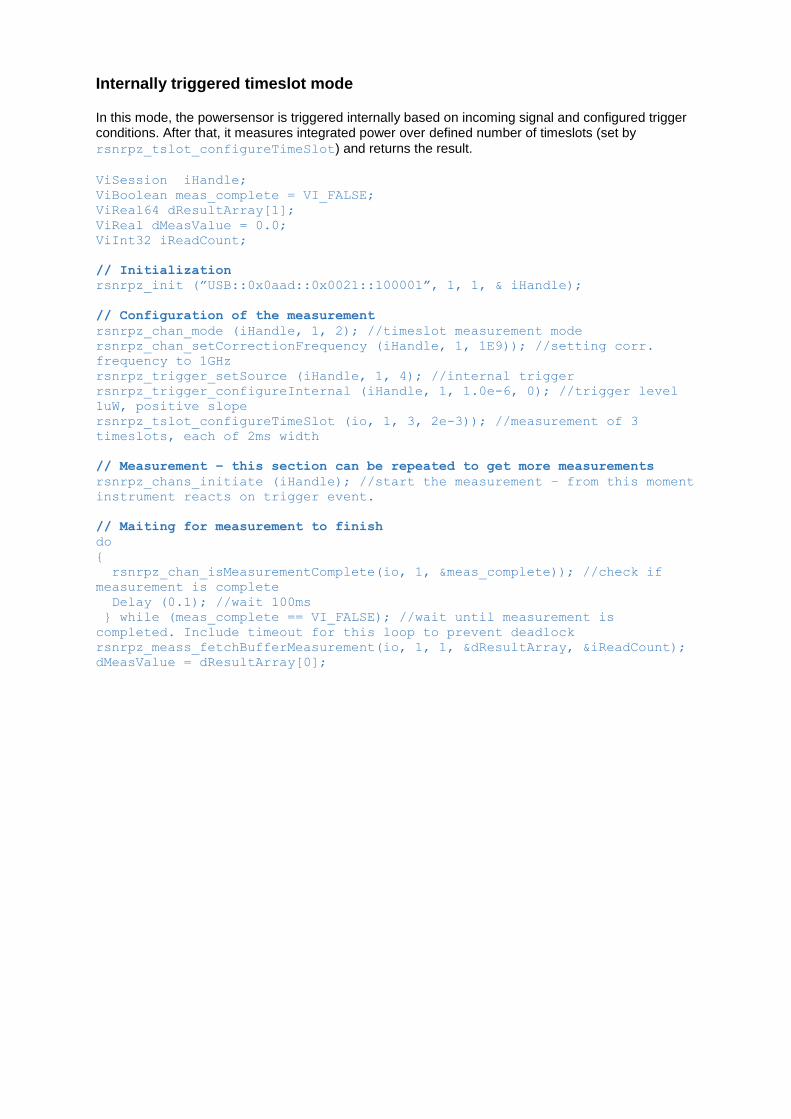
Internally triggered timeslot mode
In this mode, the powersensor is triggered internally based on incoming signal and configured trigger conditions. After that, it measures integrated power over defined number of timeslots (set by
rsnrpz_tslot_configureTimeSlot) and returns the result.
ViSession iHandle;
ViBoolean meas_complete = VI_FALSE;
ViReal64 dResultArray[1];
ViReal dMeasValue = 0.0;
ViInt32 iReadCount;
// Initialization
rsnrpz_init (”USB::0x0aad::0x0021::100001”, 1, 1, & iHandle);
// Configuration of the measurement
rsnrpz_chan_mode (iHandle, 1, 2); //timeslot measurement mode
rsnrpz_chan_setCorrectionFrequency (iHandle, 1, 1E9)); //setting corr.
frequency to 1GHz
rsnrpz_trigger_setSource (iHandle, 1, 4); //internal trigger
rsnrpz_trigger_configureInternal (iHandle, 1, 1.0e-6, 0); //trigger level
1uW, positive slope
rsnrpz_tslot_configureTimeSlot (io, 1, 3, 2e-3)); //measurement of 3
timeslots, each of 2ms width
// Measurement – this section can be repeated to get more measurements
rsnrpz_chans_initiate (iHandle); //start the measurement – from this moment
instrument reacts on trigger event.
// Maiting for measurement to finish
do
{
rsnrpz_chan_isMeasurementComplete(io, 1, &meas_complete)); //check if
measurement is complete
Delay (0.1); //wait 100ms
} while (meas_complete == VI_FALSE); //wait until measurement is
completed. Include timeout for this loop to prevent deadlock
rsnrpz_meass_fetchBufferMeasurement(io, 1, 1, &dResultArray, &iReadCount);
dMeasValue = dResultArray[0];
About Rohde & Schwarz
The Rohde & Schwarz electronics group
offers innovative solutions in the following
business fields: test and measurement,
broadcast and media, secure
communications, cybersecurity,
radiomonitoring and radiolocation. Founded
more than 80 years ago, this independent
company has an extensive sales and service
network and is present in more than 70
countries.
The electronics group is among the world
market leaders in its established business
fields. The company is headquartered in
Munich, Germany. It also has regional
headquarters in Singapore and Columbia,
Maryland, USA, to manage its operations in
these regions.
Environmental commitment
● Energy-efficient products
● Continuous improvement in
environmental sustainability
● ISO 14001-certified environmental
management system
Regional contact
Europe, Africa, Middle East
+49 89 4129 12345
[email protected] North America
1-888-TEST-RSA (1-888-837-8772)
[email protected] Latin America
+1-410-910-7988
[email protected] Asia/Pacific
+65 65 13 04 88
R&S® is a registered trademark of Rohde & Schwarz GmbH & Co. KG; Trade names are trademarks of the owners.
Rohde & Schwarz GmbH & Co. KG
Mühldorfstraße 15 | D - 81671 München
Phone + 49 89 4129 - 0 | Fax + 49 89 4129 – 13777
www.rohde-schwarz.com