hp 6890 series gas chromatographaimanalytical.com/manuals/hp 6890gc-s/6890 vol two-s.pdf · chapter...
TRANSCRIPT

Operating ManualVolume 2. Inlets
HP 6890 SeriesGas Chromatograph

Little Falls OperationHewlett-Packard Company2850 Centerville RoadWilmington, DE 19808-1610
.Hewlett-PackardCompany 1989—1996
All Rights Reserved.Reproduction, adaptation,or translation withoutpermission is prohibited,except as allowed underthe copyright laws.
HP part numberG1530-90450
First Edition, Oct 1996
Replaces parts ofG153090310 OperatingManual and parts ofG153090320 Maintenanceand TroubleshootingManual
Printed in USA
WarrantyThe information containedin this document is subjectto change without notice.
Hewlett-Packard makes nowarranty of any kind withregard to this material,including, but not limitedto, the implied warrantiesof merchantability andfitness for a particularpurpose. Hewlett-Packardshall not be liable for errorscontained herein or forincidental or consequentialdamages in connection withthe furnishing,performance, or use of thismaterial.
Safety InformationThe HP 6890 GasChromatograph meets thefollowing IEC(InternationalElectrotechnicalCommission) classifications:Safety Class 1, TransientOvervoltage Category II,and Pollution Degree 2.This unit has beendesigned and tested inaccordance with recognizedsafety standards anddesigned for use indoors. Ifthe instrument is used in amanner not specified by themanufacturer, theprotection provided by theinstrument may beimpaired. Whenever thesafety protection of the HP6890 has beencompromised, disconnectthe unit from all powersources and secure the unitagainst unintendedoperation.Refer servicing to qualifiedservice personnel.Substituting parts orperforming anyunauthorized modificationto the instrument mayresult in a safety hazard.Disconnect the AC powercord before removingcovers. The customershould not attempt toreplace the battery or fusesin this instrument. Thebattery contained in thisinstrument is recyclable.
Safety SymbolsWarnings in the manual oron the instrument must beobserved during all phasesof operation, service, andrepair of this instrument.Failure to comply withthese precautions violatessafety standards of designand the intended use of theinstrument.Hewlett-Packard Companyassumes no liability for thecustomer’s failure tocomply with theserequirements.
WARNING
A warning calls attentionto a condition or possiblesituation that could causeinjury to the user.
CAUTION
A caution calls attention toa condition or possiblesituation that coulddamage or destroy theproduct or the user’s work.
Caution. Refer toaccompanyingdocuments.
Indicates a hotsurface.
Indicates hazardousvoltages.
Indicates earth(ground) terminal.
Indicates radio-activity hazard.
Indicates explosionhazard.
Important UserInformation for In VitroDiagnostic ApplicationsThis is a multipurposeproduct that may be usedfor qualitative orquantitative analyses inmany applications. If usedin conjunction with provenprocedures (methodology)by qualified operator, oneof these applications maybe In Vitro DiagnosticProcedures.Generalized instrumentperformance characteristicsand instructions areincluded in this manual.Specific In Vitro Diagnosticprocedures andmethodology remain thechoice and theresponsibility of the user,and are not included.
Sound EmissionCertification for FederalRepublic of GermanySound pressure Lp< 65 dB(A)During normal operationAt the operator positionAccording to ISO 7779(Type Test)When operating the HP6890 with cryo valveoption, the sound pressure74.6 dB(A) during cryovalve operation for shortburst pulses.
SchallemissionSchalldruckpegel LP< 65 dB(A)Am ArbeitsplatzNormaler BetriebNach DIN 45635 T. 19(Typprüfung)Bei Betrieb des HP 6890mit Cryo Ventil Optiontreten beim Oeffnen desVentils impulsfoermigSchalldrucke Lp bis ca.74.6 dB(A) auf.
Contents
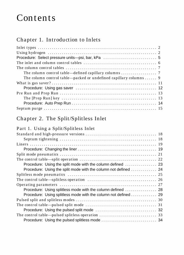
Chapter 1. Introduction to InletsInlet types 2. . . . . . . . . . . . . . . . . . . . . . . . . . . . . . . . . . . . . . . . . . . . . . . . . . . . . . . . . . . .Using hydrogen 2. . . . . . . . . . . . . . . . . . . . . . . . . . . . . . . . . . . . . . . . . . . . . . . . . . . . . . .Procedure: Select pressure units—psi, bar, kPa 5. . . . . . . . . . . . . . . . . . . . . . . . . . .The inlet and column control tables 6. . . . . . . . . . . . . . . . . . . . . . . . . . . . . . . . . . . . .The column control tables 7. . . . . . . . . . . . . . . . . . . . . . . . . . . . . . . . . . . . . . . . . . . . . .
The column control table—defined capillary columns 7. . . . . . . . . . . . . . . . . .The column control table—packed or undefined capillary columns 9. . . . . .
What is gas saver? 11. . . . . . . . . . . . . . . . . . . . . . . . . . . . . . . . . . . . . . . . . . . . . . . . . . . . .Procedure: Using gas saver 12. . . . . . . . . . . . . . . . . . . . . . . . . . . . . . . . . . . . . . . . .
Pre Run and Prep Run 13. . . . . . . . . . . . . . . . . . . . . . . . . . . . . . . . . . . . . . . . . . . . . . . . .The [Prep Run] key 13. . . . . . . . . . . . . . . . . . . . . . . . . . . . . . . . . . . . . . . . . . . . . . . .Procedure: Auto Prep Run 14. . . . . . . . . . . . . . . . . . . . . . . . . . . . . . . . . . . . . . . . . . .
Septum purge 15. . . . . . . . . . . . . . . . . . . . . . . . . . . . . . . . . . . . . . . . . . . . . . . . . . . . . . . . .
Chapter 2. The Split/Splitless Inlet
Part 1. Using a Split/Splitless InletStandard and high-pressure versions 18. . . . . . . . . . . . . . . . . . . . . . . . . . . . . . . . . . . .
Septum tightening 18. . . . . . . . . . . . . . . . . . . . . . . . . . . . . . . . . . . . . . . . . . . . . . . . .Liners 19. . . . . . . . . . . . . . . . . . . . . . . . . . . . . . . . . . . . . . . . . . . . . . . . . . . . . . . . . . . . . . . .
Procedure: Changing the liner 19. . . . . . . . . . . . . . . . . . . . . . . . . . . . . . . . . . . . . . . .Split mode pneumatics 21. . . . . . . . . . . . . . . . . . . . . . . . . . . . . . . . . . . . . . . . . . . . . . . . .The control table—split operation 22. . . . . . . . . . . . . . . . . . . . . . . . . . . . . . . . . . . . . . .
Procedure: Using the split mode with the column defined 23. . . . . . . . . . . . . . . .Procedure: Using the split mode with the column not defined 24. . . . . . . . . . . . .
Splitless mode pneumatics 25. . . . . . . . . . . . . . . . . . . . . . . . . . . . . . . . . . . . . . . . . . . . .The control table—splitless operation 26. . . . . . . . . . . . . . . . . . . . . . . . . . . . . . . . . . .Operating parameters 27. . . . . . . . . . . . . . . . . . . . . . . . . . . . . . . . . . . . . . . . . . . . . . . . .
Procedure: Using splitless mode with the column defined 28. . . . . . . . . . . . . . . .Procedure: Using splitless mode with the column not defined 29. . . . . . . . . . . . .
Pulsed split and splitless modes 30. . . . . . . . . . . . . . . . . . . . . . . . . . . . . . . . . . . . . . . . .The control table—pulsed split mode 31. . . . . . . . . . . . . . . . . . . . . . . . . . . . . . . . . . . .
Procedure: Using the pulsed split mode 32. . . . . . . . . . . . . . . . . . . . . . . . . . . . . . .The control table—pulsed splitless operation 33. . . . . . . . . . . . . . . . . . . . . . . . . . . . .
Procedure: Using the pulsed splitless mode 34. . . . . . . . . . . . . . . . . . . . . . . . . . . .

Part 2. Maintaining a Split/Splitless InletChanging septa 36. . . . . . . . . . . . . . . . . . . . . . . . . . . . . . . . . . . . . . . . . . . . . . . . . . . . . . .
Procedure: Changing the septum 37. . . . . . . . . . . . . . . . . . . . . . . . . . . . . . . . . . . . .Changing the O-ring 39. . . . . . . . . . . . . . . . . . . . . . . . . . . . . . . . . . . . . . . . . . . . . . . . . . .
Procedure: Changing the O-ring 41. . . . . . . . . . . . . . . . . . . . . . . . . . . . . . . . . . . . . .Replacing the inlet base seal 43. . . . . . . . . . . . . . . . . . . . . . . . . . . . . . . . . . . . . . . . . . .
Procedure: Replacing the inlet base seal 44. . . . . . . . . . . . . . . . . . . . . . . . . . . . . .Procedure: Leak testing the gas plumbing 46. . . . . . . . . . . . . . . . . . . . . . . . . . . . . . . . .
Procedure: Leak testing an EPC split/splitless inlet 47. . . . . . . . . . . . . . . . . . . . . .Procedure: Leak testing a nonEPC split/splitless inlet 51. . . . . . . . . . . . . . . . . . .Procedure: Correcting leaks 53. . . . . . . . . . . . . . . . . . . . . . . . . . . . . . . . . . . . . . . . .
Procedure: Cleaning the inlet 54. . . . . . . . . . . . . . . . . . . . . . . . . . . . . . . . . . . . . . . . . . . .
Chapter 3. The Purged Packed Inlet
Part 1. Using a Purged Packed InletLiners and inserts 59. . . . . . . . . . . . . . . . . . . . . . . . . . . . . . . . . . . . . . . . . . . . . . . . . . . . .
Procedure: Installing liners 61. . . . . . . . . . . . . . . . . . . . . . . . . . . . . . . . . . . . . . . . . .Procedure: Installing glass inserts 63. . . . . . . . . . . . . . . . . . . . . . . . . . . . . . . . . . . .
The control table 65. . . . . . . . . . . . . . . . . . . . . . . . . . . . . . . . . . . . . . . . . . . . . . . . . . . . . .Packed columns or column not defined 65. . . . . . . . . . . . . . . . . . . . . . . . . . . . . . .Defined capillary columns 65. . . . . . . . . . . . . . . . . . . . . . . . . . . . . . . . . . . . . . . . . .Procedure: Using packed and undefined capillary columns 66. . . . . . . . . . . . . . .Procedure: Using defined capillary columns 66. . . . . . . . . . . . . . . . . . . . . . . . . . . .
Part 2. Maintaining a Purged Packed InletProcedure: Changing septa 68. . . . . . . . . . . . . . . . . . . . . . . . . . . . . . . . . . . . . . . . . . . . .Procedure: Changing the O-ring 72. . . . . . . . . . . . . . . . . . . . . . . . . . . . . . . . . . . . . . . . .Procedure: Leak testing the gas plumbing 74. . . . . . . . . . . . . . . . . . . . . . . . . . . . . . . . .
Procedure: Leak testing an EPC purged packed inlet 75. . . . . . . . . . . . . . . . . . . .Procedure: Leak testing a nonEPC purged packed inlet 78. . . . . . . . . . . . . . . . .Procedure: Correcting leaks 80. . . . . . . . . . . . . . . . . . . . . . . . . . . . . . . . . . . . . . . . .
Procedure: Cleaning the inlet 81. . . . . . . . . . . . . . . . . . . . . . . . . . . . . . . . . . . . . . . . . . . .

Chapter 4. The Cool On-Column Inlet
Part 1. Using a Cool On-Column InletHardware 85. . . . . . . . . . . . . . . . . . . . . . . . . . . . . . . . . . . . . . . . . . . . . . . . . . . . . . . . . . . .Automatic or manual injection with septum nut 87. . . . . . . . . . . . . . . . . . . . . . . . . .Manual injection with a cooling tower and duckbill septum 88. . . . . . . . . . . . . . .Procedure: Changing the septum nut or cooling tower and septum 89. . . . . . . . . . .
Procedure: Installing an insert 90. . . . . . . . . . . . . . . . . . . . . . . . . . . . . . . . . . . . . . . .Procedure: Check the needle-to-column size 91. . . . . . . . . . . . . . . . . . . . . . . . . . .
Procedure: Manual injection with septum nut 92. . . . . . . . . . . . . . . . . . . . . . . . . . . . . .Procedure: Manual injection with cooling tower 93. . . . . . . . . . . . . . . . . . . . . . . . . . . . .Retention gaps 94. . . . . . . . . . . . . . . . . . . . . . . . . . . . . . . . . . . . . . . . . . . . . . . . . . . . . . . .Inlet temperature 94. . . . . . . . . . . . . . . . . . . . . . . . . . . . . . . . . . . . . . . . . . . . . . . . . . . . .
CryoBlast (optional) 94. . . . . . . . . . . . . . . . . . . . . . . . . . . . . . . . . . . . . . . . . . . . . . . .Track oven mode 94. . . . . . . . . . . . . . . . . . . . . . . . . . . . . . . . . . . . . . . . . . . . . . . . . .Temperature programming mode 95. . . . . . . . . . . . . . . . . . . . . . . . . . . . . . . . . . .Cryogenic considerations 95. . . . . . . . . . . . . . . . . . . . . . . . . . . . . . . . . . . . . . . . . . .Setpoint ranges 95. . . . . . . . . . . . . . . . . . . . . . . . . . . . . . . . . . . . . . . . . . . . . . . . . . . .Procedure: Programming the temperature 96. . . . . . . . . . . . . . . . . . . . . . . . . . . . .
Procedure: Operating the cool on-column inlet 97. . . . . . . . . . . . . . . . . . . . . . . . . . . . .
Part 2. Maintaining a Cool On-Column InletCool on-column inlet hardware problems 100. . . . . . . . . . . . . . . . . . . . . . . . . . . . . . . .
The inlet cools very slowly 100. . . . . . . . . . . . . . . . . . . . . . . . . . . . . . . . . . . . . . . . . .The inlet is unable to reach a temperature setpoint 100. . . . . . . . . . . . . . . . . . .The syringe needle bends during injections 100. . . . . . . . . . . . . . . . . . . . . . . . . . .
Procedure: Replacing the fused silica syringe needle 101. . . . . . . . . . . . . . . . . . . . . . .Procedure: Installing a fused silica needle 102. . . . . . . . . . . . . . . . . . . . . . . . . . . . . . . . .Changing septa 103. . . . . . . . . . . . . . . . . . . . . . . . . . . . . . . . . . . . . . . . . . . . . . . . . . . . . . .
Procedure: Changing septa 104. . . . . . . . . . . . . . . . . . . . . . . . . . . . . . . . . . . . . . . . . .Procedure: Cleaning the inlet 106. . . . . . . . . . . . . . . . . . . . . . . . . . . . . . . . . . . . . . . . . . . .Procedure: Leak testing the gas plumbing 109. . . . . . . . . . . . . . . . . . . . . . . . . . . . . . . . .Procedure: Leak testing a cool on-column inlet 110. . . . . . . . . . . . . . . . . . . . . . . . . . . . .Procedure: Correcting leaks 113. . . . . . . . . . . . . . . . . . . . . . . . . . . . . . . . . . . . . . . . . . . . .
Chapter 5. The Programmable Temperature Vaporization Inlet
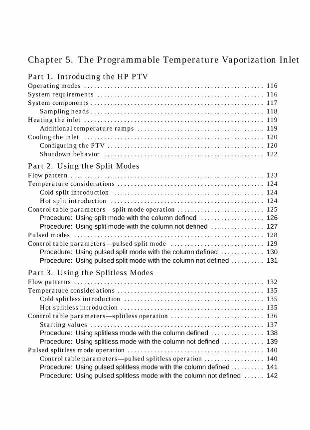
Part 1. Introducing the HP PTVOperating modes 116. . . . . . . . . . . . . . . . . . . . . . . . . . . . . . . . . . . . . . . . . . . . . . . . . . . . . .System requirements 116. . . . . . . . . . . . . . . . . . . . . . . . . . . . . . . . . . . . . . . . . . . . . . . . . .System components 117. . . . . . . . . . . . . . . . . . . . . . . . . . . . . . . . . . . . . . . . . . . . . . . . . . . .
Sampling heads 118. . . . . . . . . . . . . . . . . . . . . . . . . . . . . . . . . . . . . . . . . . . . . . . . . . . .Heating the inlet 119. . . . . . . . . . . . . . . . . . . . . . . . . . . . . . . . . . . . . . . . . . . . . . . . . . . . . .
Additional temperature ramps 119. . . . . . . . . . . . . . . . . . . . . . . . . . . . . . . . . . . . . .Cooling the inlet 120. . . . . . . . . . . . . . . . . . . . . . . . . . . . . . . . . . . . . . . . . . . . . . . . . . . . . .
Configuring the PTV 120. . . . . . . . . . . . . . . . . . . . . . . . . . . . . . . . . . . . . . . . . . . . . . .Shutdown behavior 122. . . . . . . . . . . . . . . . . . . . . . . . . . . . . . . . . . . . . . . . . . . . . . . .
Part 2. Using the Split ModesFlow pattern 123. . . . . . . . . . . . . . . . . . . . . . . . . . . . . . . . . . . . . . . . . . . . . . . . . . . . . . . . . .Temperature considerations 124. . . . . . . . . . . . . . . . . . . . . . . . . . . . . . . . . . . . . . . . . . . .
Cold split introduction 124. . . . . . . . . . . . . . . . . . . . . . . . . . . . . . . . . . . . . . . . . . . . .Hot split introduction 124. . . . . . . . . . . . . . . . . . . . . . . . . . . . . . . . . . . . . . . . . . . . . .
Control table parameters—split mode operation 125. . . . . . . . . . . . . . . . . . . . . . . . . .Procedure: Using split mode with the column defined 126. . . . . . . . . . . . . . . . . . .Procedure: Using split mode with the column not defined 127. . . . . . . . . . . . . . . .
Pulsed modes 128. . . . . . . . . . . . . . . . . . . . . . . . . . . . . . . . . . . . . . . . . . . . . . . . . . . . . . . . .Control table parameters—pulsed split mode 129. . . . . . . . . . . . . . . . . . . . . . . . . . . .
Procedure: Using pulsed split mode with the column defined 130. . . . . . . . . . . . .Procedure: Using pulsed split mode with the column not defined 131. . . . . . . . . .
Part 3. Using the Splitless ModesFlow patterns 132. . . . . . . . . . . . . . . . . . . . . . . . . . . . . . . . . . . . . . . . . . . . . . . . . . . . . . . . .Temperature considerations 135. . . . . . . . . . . . . . . . . . . . . . . . . . . . . . . . . . . . . . . . . . . .
Cold splitless introduction 135. . . . . . . . . . . . . . . . . . . . . . . . . . . . . . . . . . . . . . . . . .Hot splitless introduction 135. . . . . . . . . . . . . . . . . . . . . . . . . . . . . . . . . . . . . . . . . . .
Control table parameters—splitless operation 136. . . . . . . . . . . . . . . . . . . . . . . . . . . .Starting values 137. . . . . . . . . . . . . . . . . . . . . . . . . . . . . . . . . . . . . . . . . . . . . . . . . . . .Procedure: Using splitless mode with the column defined 138. . . . . . . . . . . . . . . .Procedure: Using splitless mode with the column not defined 139. . . . . . . . . . . . .
Pulsed splitless mode operation 140. . . . . . . . . . . . . . . . . . . . . . . . . . . . . . . . . . . . . . . . .Control table parameters—pulsed splitless operation 140. . . . . . . . . . . . . . . . . .Procedure: Using pulsed splitless mode with the column defined 141. . . . . . . . . .Procedure: Using pulsed splitless mode with the column not defined 142. . . . . .

Part 4. Using the Solvent Vent ModeFlow patterns 143. . . . . . . . . . . . . . . . . . . . . . . . . . . . . . . . . . . . . . . . . . . . . . . . . . . . . . . . .Temperature, pressure, and flow considerations 145. . . . . . . . . . . . . . . . . . . . . . . . . .Sequence of operations 146. . . . . . . . . . . . . . . . . . . . . . . . . . . . . . . . . . . . . . . . . . . . . . . . .Timelines 147. . . . . . . . . . . . . . . . . . . . . . . . . . . . . . . . . . . . . . . . . . . . . . . . . . . . . . . . . . . . .When is Start Run? 148. . . . . . . . . . . . . . . . . . . . . . . . . . . . . . . . . . . . . . . . . . . . . . . . . . . .Control table parameters—solvent vent operation 149. . . . . . . . . . . . . . . . . . . . . . . .
Procedure: Using solvent vent mode with the column defined 151. . . . . . . . . . . .Procedure: Using solvent vent mode with the column not defined 152. . . . . . . . .
Large volume injection 153. . . . . . . . . . . . . . . . . . . . . . . . . . . . . . . . . . . . . . . . . . . . . . . . .Gas chromatograph requirements 153. . . . . . . . . . . . . . . . . . . . . . . . . . . . . . . . . . .Automatic sampler requirements 153. . . . . . . . . . . . . . . . . . . . . . . . . . . . . . . . . . . .ChemStation requirements 154. . . . . . . . . . . . . . . . . . . . . . . . . . . . . . . . . . . . . . . . .Control parameters—Injector configuration subscreen 154. . . . . . . . . . . . . . . .Control parameters—Injector screen 155. . . . . . . . . . . . . . . . . . . . . . . . . . . . . . . .Calculated values 155. . . . . . . . . . . . . . . . . . . . . . . . . . . . . . . . . . . . . . . . . . . . . . . . . .
Part 5. Maintaining a PTVInlet adapters 161. . . . . . . . . . . . . . . . . . . . . . . . . . . . . . . . . . . . . . . . . . . . . . . . . . . . . . . . .
Procedure: Replacing inlet adapters 161. . . . . . . . . . . . . . . . . . . . . . . . . . . . . . . . . .Procedure: Installing columns 162. . . . . . . . . . . . . . . . . . . . . . . . . . . . . . . . . . . . . . . . . . .The septumless head 164. . . . . . . . . . . . . . . . . . . . . . . . . . . . . . . . . . . . . . . . . . . . . . . . . .
Procedure: Removing the septumless head 164. . . . . . . . . . . . . . . . . . . . . . . . . . . .Procedure: Cleaning the septumless head 165. . . . . . . . . . . . . . . . . . . . . . . . . . . . .Procedure: Replacing the Teflon ferrule 167. . . . . . . . . . . . . . . . . . . . . . . . . . . . . . .
The septum head 168. . . . . . . . . . . . . . . . . . . . . . . . . . . . . . . . . . . . . . . . . . . . . . . . . . . . . .Procedure: Removing the septum head 169. . . . . . . . . . . . . . . . . . . . . . . . . . . . . . .Procedure: Changing the septum 170. . . . . . . . . . . . . . . . . . . . . . . . . . . . . . . . . . . . .
Glass inlet liners 171. . . . . . . . . . . . . . . . . . . . . . . . . . . . . . . . . . . . . . . . . . . . . . . . . . . . . .Procedure: Replacing liners 172. . . . . . . . . . . . . . . . . . . . . . . . . . . . . . . . . . . . . . . . . .
Consumables and replaceable parts 174. . . . . . . . . . . . . . . . . . . . . . . . . . . . . . . . . . . . .
Chapter 6. The Volatiles Interface
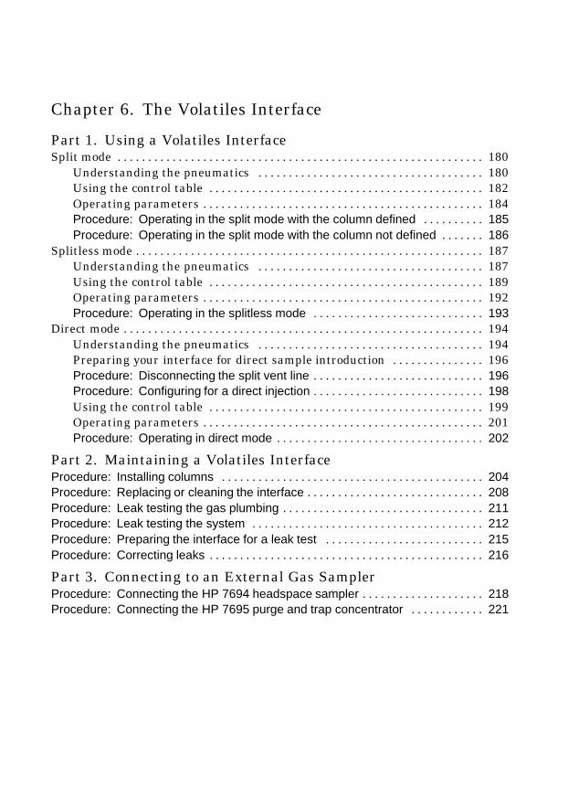
Part 1. Using a Volatiles InterfaceSplit mode 180. . . . . . . . . . . . . . . . . . . . . . . . . . . . . . . . . . . . . . . . . . . . . . . . . . . . . . . . . . . .
Understanding the pneumatics 180. . . . . . . . . . . . . . . . . . . . . . . . . . . . . . . . . . . . .Using the control table 182. . . . . . . . . . . . . . . . . . . . . . . . . . . . . . . . . . . . . . . . . . . . .Operating parameters 184. . . . . . . . . . . . . . . . . . . . . . . . . . . . . . . . . . . . . . . . . . . . . .Procedure: Operating in the split mode with the column defined 185. . . . . . . . . .Procedure: Operating in the split mode with the column not defined 186. . . . . . .
Splitless mode 187. . . . . . . . . . . . . . . . . . . . . . . . . . . . . . . . . . . . . . . . . . . . . . . . . . . . . . . . .Understanding the pneumatics 187. . . . . . . . . . . . . . . . . . . . . . . . . . . . . . . . . . . . .Using the control table 189. . . . . . . . . . . . . . . . . . . . . . . . . . . . . . . . . . . . . . . . . . . . .Operating parameters 192. . . . . . . . . . . . . . . . . . . . . . . . . . . . . . . . . . . . . . . . . . . . . .Procedure: Operating in the splitless mode 193. . . . . . . . . . . . . . . . . . . . . . . . . . . .
Direct mode 194. . . . . . . . . . . . . . . . . . . . . . . . . . . . . . . . . . . . . . . . . . . . . . . . . . . . . . . . . . .Understanding the pneumatics 194. . . . . . . . . . . . . . . . . . . . . . . . . . . . . . . . . . . . .Preparing your interface for direct sample introduction 196. . . . . . . . . . . . . . .Procedure: Disconnecting the split vent line 196. . . . . . . . . . . . . . . . . . . . . . . . . . . .Procedure: Configuring for a direct injection 198. . . . . . . . . . . . . . . . . . . . . . . . . . . .Using the control table 199. . . . . . . . . . . . . . . . . . . . . . . . . . . . . . . . . . . . . . . . . . . . .Operating parameters 201. . . . . . . . . . . . . . . . . . . . . . . . . . . . . . . . . . . . . . . . . . . . . .Procedure: Operating in direct mode 202. . . . . . . . . . . . . . . . . . . . . . . . . . . . . . . . . .
Part 2. Maintaining a Volatiles InterfaceProcedure: Installing columns 204. . . . . . . . . . . . . . . . . . . . . . . . . . . . . . . . . . . . . . . . . . .Procedure: Replacing or cleaning the interface 208. . . . . . . . . . . . . . . . . . . . . . . . . . . . .Procedure: Leak testing the gas plumbing 211. . . . . . . . . . . . . . . . . . . . . . . . . . . . . . . . .Procedure: Leak testing the system 212. . . . . . . . . . . . . . . . . . . . . . . . . . . . . . . . . . . . . .Procedure: Preparing the interface for a leak test 215. . . . . . . . . . . . . . . . . . . . . . . . . .Procedure: Correcting leaks 216. . . . . . . . . . . . . . . . . . . . . . . . . . . . . . . . . . . . . . . . . . . . .
Part 3. Connecting to an External Gas SamplerProcedure: Connecting the HP 7694 headspace sampler 218. . . . . . . . . . . . . . . . . . . .Procedure: Connecting the HP 7695 purge and trap concentrator 221. . . . . . . . . . . .
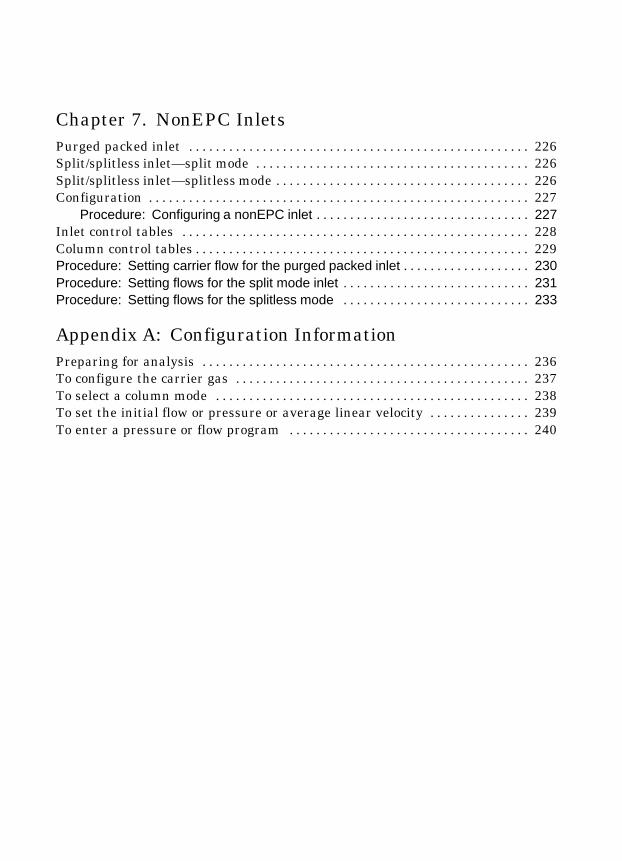
Chapter 7. NonEPC InletsPurged packed inlet 226. . . . . . . . . . . . . . . . . . . . . . . . . . . . . . . . . . . . . . . . . . . . . . . . . . .Split/splitless inlet—split mode 226. . . . . . . . . . . . . . . . . . . . . . . . . . . . . . . . . . . . . . . . .Split/splitless inlet—splitless mode 226. . . . . . . . . . . . . . . . . . . . . . . . . . . . . . . . . . . . . .Configuration 227. . . . . . . . . . . . . . . . . . . . . . . . . . . . . . . . . . . . . . . . . . . . . . . . . . . . . . . . .
Procedure: Configuring a nonEPC inlet 227. . . . . . . . . . . . . . . . . . . . . . . . . . . . . . . .Inlet control tables 228. . . . . . . . . . . . . . . . . . . . . . . . . . . . . . . . . . . . . . . . . . . . . . . . . . . .Column control tables 229. . . . . . . . . . . . . . . . . . . . . . . . . . . . . . . . . . . . . . . . . . . . . . . . . .Procedure: Setting carrier flow for the purged packed inlet 230. . . . . . . . . . . . . . . . . . .Procedure: Setting flows for the split mode inlet 231. . . . . . . . . . . . . . . . . . . . . . . . . . . .Procedure: Setting flows for the splitless mode 233. . . . . . . . . . . . . . . . . . . . . . . . . . . .
Appendix A: Configuration InformationPreparing for analysis 236. . . . . . . . . . . . . . . . . . . . . . . . . . . . . . . . . . . . . . . . . . . . . . . . .To configure the carrier gas 237. . . . . . . . . . . . . . . . . . . . . . . . . . . . . . . . . . . . . . . . . . . .To select a column mode 238. . . . . . . . . . . . . . . . . . . . . . . . . . . . . . . . . . . . . . . . . . . . . . .To set the initial flow or pressure or average linear velocity 239. . . . . . . . . . . . . . .To enter a pressure or flow program 240. . . . . . . . . . . . . . . . . . . . . . . . . . . . . . . . . . . .

1
Introductionto Inlets
Inlet types, 2Using hydrogen, 2Procedure: Select pressure units—psi, bar, kPa, 5The inlet and column control tables, 6The column control tables, 7
Defined capillary columns, 7Packed or undefined capillary columns, 9
What is gas saver?, 11Procedure: Using gas saver, 12
Pre Run and Prep Run, 13The [Prep Run] key, 13Procedure: Auto Prep Run, 14
Septum purge, 15
2
Chapter 1.Introduction to Inlets
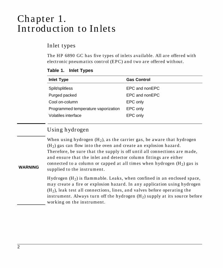
Inlet types
The HP 6890 GC has five types of inlets available. All are offered withelectronic pneumatics control (EPC) and two are offered without.
Table 1. Inlet Types
Inlet Type Gas Control
Split/splitless EPC and nonEPC
Purged packed EPC and nonEPC
Cool on-column EPC only
Programmed temperature vaporization EPC only
Volatiles interface EPC only
Using hydrogen
When using hydrogen (H2), as the carrier gas, be aware that hydrogen(H2) gas can flow into the oven and create an explosion hazard.Therefore, be sure that the supply is off until all connections are made,and ensure that the inlet and detector column fittings are eitherconnected to a column or capped at all times when hydrogen (H2) gas issupplied to the instrument.
Hydrogen (H2) is flammable. Leaks, when confined in an enclosed space,may create a fire or explosion hazard. In any application using hydrogen(H2), leak test all connections, lines, and valves before operating theinstrument. Always turn off the hydrogen (H2) supply at its source beforeworking on the instrument.
WARNING

3
Inlets
Table 2. An Overview of Inlets
Inlet Type Columntype Mode Sample type Comments
Sampleto Col-umn
Split/splitless Capillary Split High concentra-tion
Very little,most isventedPulsed split High concentra-
tionNew technique; may be usefulwith large (>2 ³L) injections
vented
Splitless Low concentration
Pulsed split-less
Low concentration Useful with large (>2 ³L)injections
Coolon-column
Capillary n/a Low concentrationor thermally labile
Minimal sample discriminationand decomposition All
Purgedpacked
Packed;1/8- and1/4-in. met-al, 1/8-in.glass
n/a Any
Large borecapillary
n/a Any Satisfactory if resolution is notan issue
ProgrammedTemperaturevaporization
Capillary Split
Pulsed split
High concentra-tion
High concentra-tion
Very little,most isvented
Splitless
Pulsed split-
Low concentration
Pulsed split-less Low concentration
AllSolvent vent Low concentration For large (>x ³L) injections;
multiple injections concentrateanalytes while venting solvent
All
Volatiles in-terface
Capillary Direct Low concentration Lowest possible dead volume Allterface
Split High concentra-tion
Max total flow = 100 mL/min Very little
Splitless Low concentration All

4
Inlets
Table 3. Column Size and Carrier Gas Flow Rate
ColumnType
Column Size Carrier Gas Flow Rate
Hydrogen Helium
Packed 1/8 in. 30
1/4 in. 60
Capillary 50 ³ id 0.5 0.4
100 ³ id 1.0 0.8
200 ³ id 2.0 1.6
250 ³ id 2.5 2.0
320 ³ id 3.2 2.6
530 ³ id 5.3 4.2
These flow rates, in mL/min at normal temperature and pres-sure ���Û& and 1 atm) are recommended for all column tem-peratures.For capillary columns, flow rates are proportional to columndiameter and are 20% lower for helium than for hydrogen.
5
Inlets
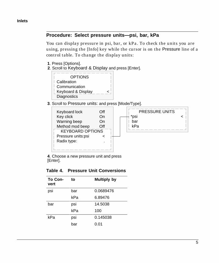
Procedure: Select pressure units—psi, bar, kPa
You can display pressure in psi, bar, or kPa. To check the units you areusing, pressing the [Info] key while the cursor is on the Pressure line of acontrol table. To change the display units:
Keyboard lock OffKey click OnWarning beep OnMethod mod beep Off
KEYBOARD OPTIONSPressure units:psi <Radix type: .
OPTIONSCalibrationCommunicationKeyboard & Display <Diagnostics
1. Press [Options].
3. Scroll to Pressure units: and press [Mode/Type].
4. Choose a new pressure unit and press[Enter].
2. Scroll to Keyboard & Display and press [Enter].
PRESSURE UNITS*psi <barkPa
Table 4. Pressure Unit Conversions
To Con-vert
to Multiply by
psi bar 0.0689476
kPa 6.89476
bar psi 14.5038
kPa 100
kPa psi 0.145038
bar 0.01

6
Inlets
The inlet and column control tables
The tables for the inlet and column are interrelated. If you set a pressureat the column control table, that same pressure setting is active on theinlet control table, and vice versa. Although pneumatics can becontrolled from either the column or the inlet, the column should beconsidered first.
COLUMN 1 (He)Dim 30.0 m 320 uPressure 10.0 10.0Flow 0.7Velocity 19Mode: Constant flow
FRONT INLET (S/SL)Mode: SplitlessTemp 250 250 <Pressure 10.0 10.0Purge time 0.75Purge flow 15Total flow ??Gas saver Off
The pressure readings—both setpoint and actual—are identical on thecolumn and inlet control tables.

7
Inlets
The column control tables
The control tables change depending on your column configuration. Thenext few pages describe the column control tables for the two types ofcolumns, capillary and packed.
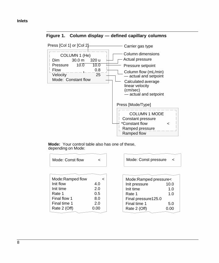
The column control table—defined capillary columns
If your column is defined, your control table will be similar to Figure 1.
The title This heading identifies the column—Column 1 or Column 2—and the type of carrier gas configured to the inlet (in parentheses).
Dim This line shows the column dimensions you have specified. Columnlength is in meters (m) and column inside diameter is in microns (³).
Pressure, flow, and velocity are related. If the column is defined, enterany one of them and the GC computes and displays the other two.
Pressure The setpoint appears at the far right. The number at the leftshows the actual pressure value. When you enter a pressure value, thevalues for flow and average linear velocity are calculated and displayed.
Flow If you enter a flow (in mL/min) here, pressure and velocity arecalculated and adjusted.
Velocity If you enter average linear velocity (in cm/sec), pressure andflow are calculated.
Mode: There are four column modes: constant flow, constant pressure,ramped flow, and ramped pressure. To change the mode, scroll to Mode :and press [Mode/Type].
The “Flow and Pressure Control” chapter of the General Informationvolume explains how to set pressure and flow programs.
8
Inlets
Figure 1. Column display — defined capillary columns
COLUMN 1 (He)Dim 30.0 m 320 uPressure 10.0 10.0Flow 0.8Velocity 25Mode: Constant flow
Press [Col 1] or [Col 2]
COLUMN 1 MODEConstant pressure
*Constant flow <Ramped pressureRamped flow
Column dimensionsActual pressure
Pressure setpoint
Column flow (mL/min)— actual and setpointCalculated averagelinear velocity(cm/sec)— actual and setpoint
Press [Mode/Type]
Mode: Your control table also has one of these,depending on Mode:
Mode:Ramped flow <Init flow 4.0Init time 2.0Rate 1 0.5Final flow 1 8.0Final time 1 2.0Rate 2 (Off) 0.00
Mode: Const flow < Mode: Const pressure <
Mode:Ramped pressure<Init pressure 10.0Init time 1.0Rate 1 1.0Final pressure125.0Final time 1 5.0Rate 2 (Off) 0.00
Carrier gas type

9
Inlets
The column control table—packed or undefined capillary columns
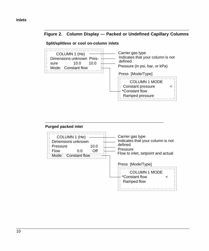
If you have not defined your column or if your inlet selection isUnspecified, your column control table will be similar to Figure 2.
The title This heading identifies the column—Column 1 or Column 2—and the type of carrier gas configured to the inlet (in parentheses).
Dimensions unknown This line tells you that you have not defined yourcolumn.
Pressure The split/splitless inlet and the cool on-column inlet arepressure controlled. Because the column is unknown, flow and averagelinear velocity cannot be computed.
The purged packed inlet is flow controlled. The actual pressure isdisplayed, but is not controllable by the user.
Mode: You have a choice of three modes if using a split/splitless or coolon-column inlet—constant pressure, constant flow, and ramped flow. Thepacked inlet gives you only the two flow modes—constant and ramped.
The “Flow and Pressure Control” chapter of the General Informationvolume explains how to set pressure and flow programs.
10
Inlets
Figure 2. Column Display — Packed or Undefined Capillary Columns
Pressure (in psi, bar, or kPa)
Indicates that your column is notdefined
COLUMN 1 (He)Dimensions unknown Pres-sure 10.0 10.0Mode: Constant flow
COLUMN 1 MODEConstant pressure <
*Constant flowRamped pressure
COLUMN 1 (He)Dimensions unknownPressure 10.0Flow 0.0 OffMode: Constant flow
COLUMN 1 MODE*Constant flow <Ramped flow
Purged packed inlet
Split/splitless or cool on-column inlets
Press [Mode/Type]
Carrier gas typeIndicates that your column is notdefined
Carrier gas type
Pressure
Press [Mode/Type]
Flow to inlet, setpoint and actual

11
Inlets
What is gas saver?
Gas saver reduces carrier gas flow from the split vent after the sample ison the column. Column head pressure and flow rate are maintained,while purge and split vent flows decrease. Flows—except columnflow—remain at the reduced level until you press [Prep Run].
You can use gas saver in all modes of operation of the Split/Splitless andPTV inlets and in the split and splitless modes of the Volatiles Interface.
Figure 3. Gas Saver Operation
Split ventflow(mL/min)
Time (min)0 1 2 3 4 5 6 7 8
Regular flow
Gas saver flow
10
20
30
40
50
í�í�
Gas saverflow
[Prep run]
[Start] Gas saver time (3 min)
Run ends
Splitmode
Split ventflow(mL/min)
Time (min)0 1 2 3 4 5 6 7 8
Gas saverflow
10
20
30
40
50
í�í�
Gas saverflow
[Prep run]
[Start] Gas saver time (5 min)
Run ends
Purge time(2 min)
Splitlessmode
Purge flow
The pulsed modes of the split/splitless and PTV inlets are similar exceptfor the pressure pulse starting at [Prep Run] and ending at Pulse time.The solvent vent mode of the PTV is more complex; see chapter 5 fordetails.

12
Inlets
Procedure: Using gas saver
Press [Front Inlet] or [Back Inlet].
Mode: SplitTemp 24 OffPressure 0.0 OffSplit ratio 10Split flow 0.0Tot flow 0.0 OffFRONT INLET (S/SL)
Gas saver OnSaver flow 20.0Saver time 2.00
1. Turn on gas saver.
2. Set a flow. Must be at least 15 mL/mingreater than the column flow.
3. If in split mode, set after injection time.In all other modes, set after purge time.
13
Inlets
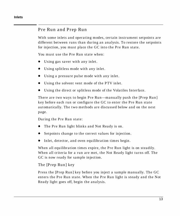
Pre Run and Prep Run
With some inlets and operating modes, certain instrument setpoints aredifferent between runs than during an analysis. To restore the setpointsfor injection, you must place the GC into the Pre Run state.
You must use the Pre Run state when:
- Using gas saver with any inlet.
- Using splitless mode with any inlet.
- Using a pressure pulse mode with any inlet.
- Using the solvent vent mode of the PTV inlet.
- Using the direct or splitless mode of the Volatiles Interface.
There are two ways to begin Pre Run—manually push the [Prep Run]key before each run or configure the GC to enter the Pre Run stateautomatically. The two methods are discussed below and on the nextpage.
During the Pre Run state:
- The Pre Run light blinks and Not Ready is on.
- Setpoints change to the correct values for injection.
- Inlet, detector, and oven equilibration times begin.
When all equilibration times expire, the Pre Run light is on steadily.When all criteria for a run are met, the Not Ready light turns off. TheGC is now ready for sample injection.
The [Prep Run] key
Press the [Prep Run] key before you inject a sample manually. The GCenters the Pre Run state. When the Pre Run light is steady and the NotReady light goes off, begin the analysis.

14
Inlets
Procedure: Auto Prep Run
With most automatic injection systems, you do not need to use the [PrepRun] key. If your sampler or automation controller (for example, anintegrator or workstation) does not support the [Prep Run] function, youmust set the GC to Auto Prep Run. To do this:
1. Press the [Config] key to view a list of configurable parameters.
2. Scroll to the Instrument parameter and press [Enter].
3. Scroll to Auto prep run and press [On].
CONFIG INSTRUMENTSerial#US00100001Auto prep run On <F inlet type NoneB inlet type PP

15
Inlets
Septum purge
The septum purge line is near the septum where the sample is injected.A small amount of carrier gas exits through this line to sweep out anybleed.
Each inlet has a different septum purge flow. The GC automatically setsthe purge flow for EPC inlets, but you can measure it from the septumpurge vent at the flow manifold if you like.
Table 5. Septum Purge Flows
Inlet Carrier Septum Purge
Split/splitless, allmodes
He, N2, Ar/5%Me 3 mL/minmodes
H2 6 mL/min
Purged packed All 1 to 3 mL/min
Cool on-column He, N2, Ar/5%Me 15 mL/min
H2 30 mL/min
PTV He, N2, Ar/5% Me 3 mL/min
H2 6 mL/min
Volatiles interface He, N2, Ar/5%Me 3 mL/min
H2 6 mL/min
Figure 4. Septum Purge Vents
Split/splitless inletPTV inletVolatiles interface
Purged packed inletCool on-column inlet
Septum purge ventSeptum purge vent
2
The Split/Splitless Inlet
Part 1. Using a Split/Splitless InletStandard and high-pressure versions, 18
Septum tightening, 18Liners, 19Split mode pneumatics, 21The control table—split operation, 22
Procedure: Split mode, column defined, 23Procedure: Split mode, column not defined, 24
Splitless mode pneumatics, 25The control table—splitless operation, 26Operating parameters, 27
Procedure: Splitless mode, column defined, 28Procedure: Splitless mode, column not defined, 29
Pulsed split and splitless modes, 30The control table—pulsed split mode, 31
Procedure: Pulsed split mode, 32The control table—pulsed splitless operation, 33
Procedure: Pulsed splitless mode, 34
Part 2. Maintaining a Split/Splitless InletChanging septa, 36Changing the O-ring, 39Replacing the inlet base seal, 43Procedure: Leak checking the gas plumbing, 46
Procedure: Leak checking EPC split/splitless inlet, 47Procedure: Leak checking nonEPC split/splitless inlet, 51Procedure: Correcting leaks, 53
Procedure: Cleaning the inlet, 54
18
Chapter 2.The Split/Splitless Inlet
Part 1. Using a Split/Splitless Inlet
This inlet is used for split, splitless, pulsed splitless, or pulsed splitanalyses. You can choose the operating mode from the inlet control table.The split mode is generally used for major component analyses, while thesplitless mode is used for trace analyses. The pulsed splitless and pulsedsplit modes are used for the same type of analyses as split or splitless,but allows you to inject larger samples.
Standard and high-pressure versionsThe standard split/splitless inlet is rated to 120 psi pressure at the gassupply fitting. It is appropriate for most columns. The high-pressure inletis rated to 170 psi pressure—it is useful with very small diametercapillary columns that offer considerable resistance to gas flow.
To determine the version that you have, press [Front Inlet] or [BackInlet], scroll to the Pressure line, and press the [Info] key. The displaywill show the pressure range for the inlet—either 1 to 100 psi (for thestandard version) or 1 to 150 psi (for the high-pressure version).
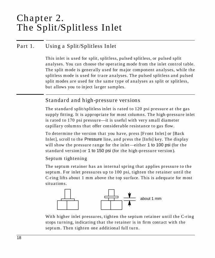
Septum tightening
The septum retainer has an internal spring that applies pressure to theseptum. For inlet pressures up to 100 psi, tighten the retainer until theC-ring lifts about 1 mm above the top surface. This is adequate for mostsituations.
about 1 mm
With higher inlet pressures, tighten the septum retainer until the C-ringstops turning, indicating that the retainer is in firm contact with theseptum. Then tighten one additional full turn.

19
Split/splitless operation
Liners
Choose liners according to the type of injection you are doing—split orsplitless. Many liners are available and can be ordered from theHewlett-Packard Analytical Columns and Supplies Catalog.
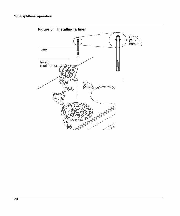
Procedure: Changing the liner
Parts list:
- Liner, HP part no. 19251-60540 (split) or 5062-3587 (splitless)- Tweezers- Septum wrench (HP part no. 19251-00100)- Viton O-ring (HP part no. 5180-4182)
1. Press [Oven] and set the oven to 35EC. When the temperaturereaches setpoint, turn the oven off. Press [Front Inlet] or [Back Inlet]and turn off the inlet temperature and pressure.
Be careful! The inlet fittings may be hot enough to cause burns.
2. Remove the insert retainer nut. Use a septum wrench, if needed.
3. If a liner is present, remove it with tweezers or a similar tool. Becareful not to chip the liner.
4. Hold the new liner with tweezers, and inspect it. Make sure it is thecorrect type for the injection mode you are using—split or splitless.
5. Place a Viton O-ring on the liner about 2 to 3 mm from its top end.
6. Press the liner straight down into the inlet.
Do not add an O-ring or other seal either at the bottom of the inlet or atthe bottom of the liner; this will damage the inlet and shatter the liner.
7. Replace the insert retainer nut, tightening it to firm finger tightness.Do not overtighten.
WARNING
Caution
20
Split/splitless operation
Figure 5. Installing a liner
Insertretainer nut
Liner
O-ring��í� mmfrom top)

21
Split/splitless operation
Split mode pneumatics
During a split injection, a liquid sample is introduced into a hot inletwhere it vaporizes rapidly. A small amount of the vapor enters thecolumn while the major portion exits from the split/purge vent. The ratioof column flow to split flow is controlled by the user. Split injections areprimarily used for high concentration samples when you can afford tolose most of the sample out the split/purge vent. It is also used forsamples that cannot be diluted.
Figure 6 shows the pneumatics for this inlet in split mode operation.
Figure 6. Split flow pneumatics
Column head pres-sure control loop
Total flowcontrol loop
To detector
Septum holder
Flowsensor
Propor-tional
valve 1
FS PS
Pressuresensor
Purgevalveopen
SPR
Septum purgeregulator (notadjustable)
Flowlimiting
frit
Split vent flow
Propor-tional
valve 2
Safety shutdown mode:Proportional valve 1 closedProportional valve 2 openPurge valve open
Trap
Vent

22
Split/splitless operation
The control table—split operation
Mode: The current operating mode—split
Temp Actual and setpoint inlet temperatures
Pressure Actual and setpoint inlet pressure
Split ratio The ratio of split flow to column flow. Column flow is set atthe Column 1 or Column 2 control table. This line does not appear ifyour column is not defined.
Split flow Flow, in mL/min, from the split/purge vent. This line does notappear if your column is not defined.
Total flow This is the total flow into the inlet, which is the sum of thesplit flow, column flow, and septum purge flow. When you change thetotal flow, the split ratio and split flow change while the column flow andpressure remain the same.
FRONT INLET MODE*Split <SplitlessPulsed splitless
Press [Mode/Type]
If using gas saver, set time afterinjection time.
FRONT INLET (S/SL)Mode: SplitTemp 250 250 <Pressure 10.0 10.0Split ratio 100Split flow 76.6Tot flow 80.3 80.3Gas saver OnSaver flow 20.0Saver time 2.00

23
Split/splitless operation
Procedure: Using the split mode with the column defined
1. See Appendix A to verify that the column, carrier gas, and flow orpressure program (if used) are configured correctly.
2. Press [Front Inlet] or [Back Inlet]
a. Scroll to Mode: and press [Mode/Type]. Select Split.
b. Set the inlet temperature.
c. If you want a specific split ratio, scroll to Split ratio and enter thatnumber. The split flow will be calculated for you.
d. If you want a specific split flow, scroll to Split flow and enter thatnumber. The split ratio will be calculated for you.
e. If desired, turn on Gas saver. Set the Saver time after theinjection time. Use the [Prep Run] key (see page 13) beforemanually injecting the sample.
FRONT INLET MODESplit <
*SplitlessPulsed splitPulsed splitless
Press [Mode/Type]
If using gas saver,set time after injectiontime.
FRONT INLET (S/SL)Mode: SplitTemp 250 250 <Pressure 10.0 10.0Split ratio 100Split flow 76.6Tot flow 80.3 80.3Gas saver OnSaver flow 20.0Saver time 2.00
Split ratio =Split flow
Column flow
24
Split/splitless operation
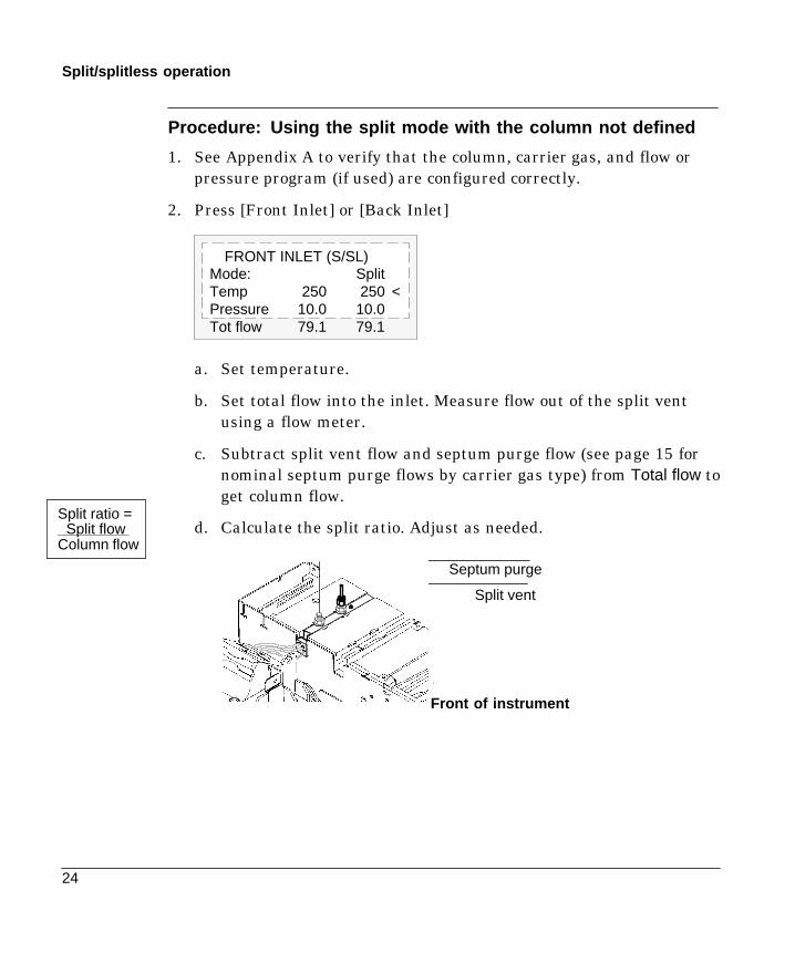
Procedure: Using the split mode with the column not defined
1. See Appendix A to verify that the column, carrier gas, and flow orpressure program (if used) are configured correctly.
2. Press [Front Inlet] or [Back Inlet]
FRONT INLET (S/SL)Mode: SplitTemp 250 250 <Pressure 10.0 10.0Tot flow 79.1 79.1
a. Set temperature.
b. Set total flow into the inlet. Measure flow out of the split ventusing a flow meter.
c. Subtract split vent flow and septum purge flow (see page 15 fornominal septum purge flows by carrier gas type) from Total flow toget column flow.
d. Calculate the split ratio. Adjust as needed.
Septum purge
Split vent
Front of instrument
Split ratio =Split flow
Column flow

25
Split/splitless operation
Splitless mode pneumatics
In this mode, the purge valve is closed during the injection and remainsso while the sample is vaporized in the liner and transferred to thecolumn. At a specified time after injection, the purge valve opens tosweep any vapors remaining in the liner out the split vent. This avoidssolvent tailing due to the large inlet volume and small column flow rate.Specify the purge time and purge flow rate in the inlet control table.
If you are using gas saver, the gas saver time should be after the purgetime.
Figure 7. Splitless Flow Diagram, Pre-Run to Purge Time
Inlet pressurecontrol loop
To detector
Septum holderFlowsensor
Proportionalvalve 1
FS PS
Pressuresensor
Purgevalveclosed
SPR
Septum purgeregulator (notadjustable)
Flowlimiting
frit
Safety shutdown mode:Proportional valve 1 closedProportional valve 2 openPurge valve open
Propor-tional
valve 2
Trap
Vent

26
Split/splitless operation
The control table—splitless operation
Mode: The current operating mode—splitless
Temp Actual and setpoint inlet temperatures
Pressure Actual and setpoint inlet pressure in psi, bar, or kPa
Purge time The time, after the beginning of the run, when you want thepurge valve to open.
Purge flow The flow, in mL/min, from the purge vent, at Purge time.You will not be able to specify this value if operating with your columnnot defined.
Total flow The Total flow line displays the actual flow to the inletduring a Pre-run (Pre-run light is on and not blinking) and during a runbefore purge time. You cannot enter a setpoint at these times. At allother times, Total flow will have both setpoint and actual values.
FRONT INLET (S/SL)Mode: SplitlessTemp 250 250 <Pressure 10.0 10.0Purge time 0.75Purge flow 15.0Total flow 77.6Gas saver OnSaver flow 20.0Saver time 2.00
If using gas saver, set savertime after purge flow time.

27
Split/splitless operation
Operating parameters
A successful splitless injection consists of these steps:
1. Vaporize the sample and solvent in a heated inlet.
2. Use a low flow and low oven temperature to create asolvent-saturated zone at the head of the column.
3. Use this zone to trap and reconcentrate the sample at the head of thecolumn.
4. Wait until all, or at least most, of the sample has transferred to thecolumn. Then discard the remaining vapor in the inlet—which ismostly solvent—by opening a purge valve. This eliminates the longsolvent tail that this vapor would otherwise cause.
5. Raise the oven temperature to release the solvent and then thesample from the head of the column.
Some experimentation is needed to refine the operating conditions.Table 5 provides starting values for the critical parameters.
Table 5. Splitless Mode Inlet Parameters
Parameter Allowed Setpoint Range Suggested StartingValue
Oven temperature No cryo, 24EC to 450ECCO2 cryo, �EC to 450ECN2 cryo, �EC to 450EC
��Û& below solventboiling point
Oven initial time 0 to 999.9 minutes | Inlet purge time
Inlet purge time 0 to 999.9 minutesColumn flowLiner volume
x 2
Gas saver time 0 to 999.9 minutes After purge time
Gas saver flow 15 to 1000 mL/min 15 mL/min greaterthan maximum col-umn flow

28
Split/splitless operation
Procedure: Using splitless mode with the column defined
1. See Appendix A to verify that the column, carrier gas, and flow orpressure program (if used) are configured correctly.
2. Press [Front Inlet] or [Back Inlet]
a. Scroll to Mode: and press [Mode/Type]. Select Splitless.
b. Set the inlet temperature.
c. Enter a purge time and a purge flow.
d. If desired, turn Gas saver on. Make certain the time is set afterthe purge flow time.
FRONT INLET (S/SL)Mode: SplitlessTemp 250 250 <Pressure 10.0 10.0Purge time 0.75Purge flow 15.0Total flow 77.6Gas saver OnSaver flow 20.0Saver time 2.00
Press [Mode/Type]
If using gas saver,set time after purge flowtime.
FRONT INLET MODESplit <
*SplitlessPulsed splitPulsed splitless
3. Use the [Prep Run] key (see page 13)before manually injecting asample.
29
Split/splitless operation
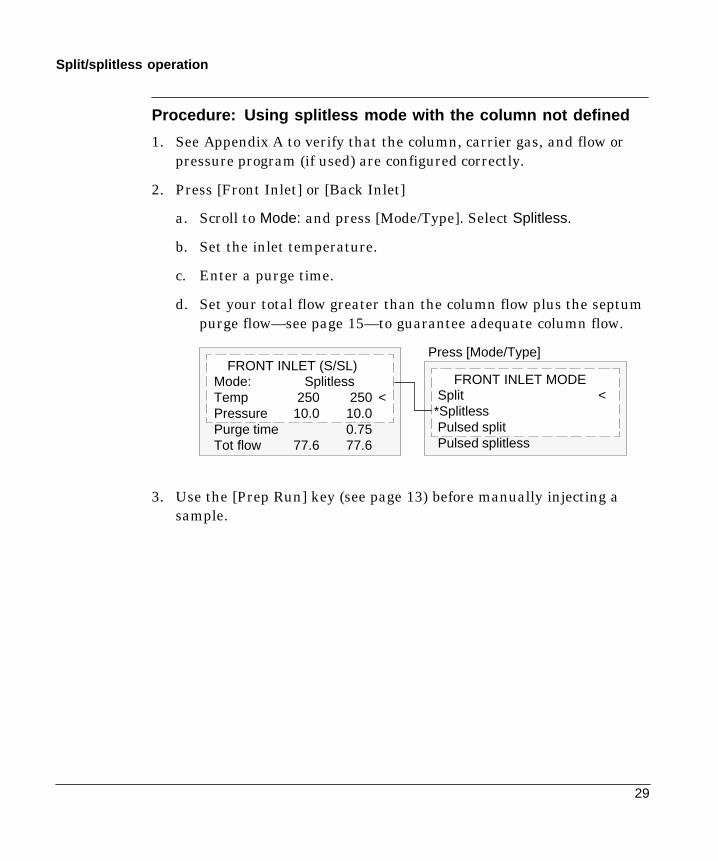
Procedure: Using splitless mode with the column not defined
1. See Appendix A to verify that the column, carrier gas, and flow orpressure program (if used) are configured correctly.
2. Press [Front Inlet] or [Back Inlet]
a. Scroll to Mode: and press [Mode/Type]. Select Splitless.
b. Set the inlet temperature.
c. Enter a purge time.
d. Set your total flow greater than the column flow plus the septumpurge flow—see page 15—to guarantee adequate column flow.
Press [Mode/Type]FRONT INLET (S/SL)
Mode: SplitlessTemp 250 250 <Pressure 10.0 10.0Purge time 0.75Tot flow 77.6 77.6
FRONT INLET MODESplit <
*SplitlessPulsed splitPulsed splitless
3. Use the [Prep Run] key (see page 13) before manually injecting asample.
30
Split/splitless operation
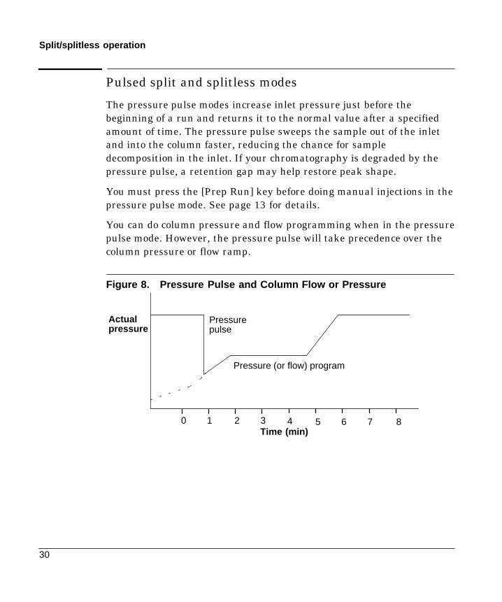
Pulsed split and splitless modes
The pressure pulse modes increase inlet pressure just before thebeginning of a run and returns it to the normal value after a specifiedamount of time. The pressure pulse sweeps the sample out of the inletand into the column faster, reducing the chance for sampledecomposition in the inlet. If your chromatography is degraded by thepressure pulse, a retention gap may help restore peak shape.
You must press the [Prep Run] key before doing manual injections in thepressure pulse mode. See page 13 for details.
You can do column pressure and flow programming when in the pressurepulse mode. However, the pressure pulse will take precedence over thecolumn pressure or flow ramp.
Figure 8. Pressure Pulse and Column Flow or Pressure
Actualpressure
Time (min)0 1 2 3 4 5 6 7 8
Pressurepulse
Pressure (or flow) program

31
Split/splitless operation
The control table—pulsed split modeMode: The current operating mode—pulsed split
Temp Actual and setpoint inlet temperatures
Pressure Actual and setpoint inlet pressure at the beginning of a run,ignoring the effect of a pressure pulse. It sets the starting point of apressure program or the fixed pressure if a program is not used.
Pulsed pres The inlet pressure you desire at the beginning of a run.The pressure rises to this setpoint after [Prep Run] is pressed andremains constant until Pulse time elapses, when it returns to Pressure.
Pulse time Pressure returns to its normal setpoint at this time.
Split ratio The ratio of split flow to column flow. Column flow is set atthe Column 1 or Column 2 control table. This line does not appear ifyour column is not defined.
Split flow Flow, in mL/min from the split/purge vent. This line does notappear if your column is not defined.
Total flow The total flow into the inlet, a sum of the split flow, columnflow, and septum purge flow. If you change the total flow, the split ratioand split flow change while the column flow and pressure remain thesame. When a pressure pulse is used, total flow increases to keep thesplit ratio constant.
FRONT INLET (S/SL)Mode: Pulsed splitTemp 250 250 <Pressure 10.0 10.0Pulsed pres 30.0Pulse time 1.0Split ratio 100Split flow 67.0Tot flow 70.9Gas saver OnSaver flow 20.0Saver time 3.00
Pressure pulsesetpoints
32
Split/splitless operation
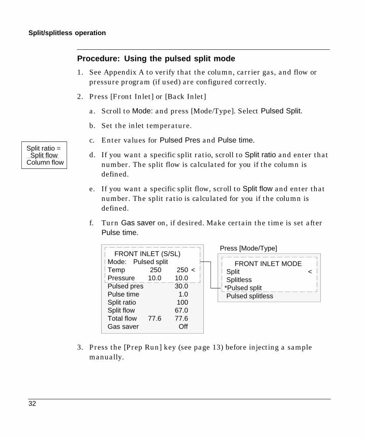
Procedure: Using the pulsed split mode
1. See Appendix A to verify that the column, carrier gas, and flow orpressure program (if used) are configured correctly.
2. Press [Front Inlet] or [Back Inlet]
a. Scroll to Mode: and press [Mode/Type]. Select Pulsed Split.
b. Set the inlet temperature.
c. Enter values for Pulsed Pres and Pulse time.
d. If you want a specific split ratio, scroll to Split ratio and enter thatnumber. The split flow is calculated for you if the column isdefined.
e. If you want a specific split flow, scroll to Split flow and enter thatnumber. The split ratio is calculated for you if the column isdefined.
f. Turn Gas saver on, if desired. Make certain the time is set afterPulse time.
FRONT INLET (S/SL)Mode: Pulsed splitTemp 250 250 <Pressure 10.0 10.0Pulsed pres 30.0Pulse time 1.0Split ratio 100Split flow 67.0Total flow 77.6 77.6Gas saver Off
Press [Mode/Type]
FRONT INLET MODESplit <Splitless
*Pulsed splitPulsed splitless
3. Press the [Prep Run] key (see page 13) before injecting a samplemanually.
Split ratio =Split flow
Column flow

33
Split/splitless operation
The control table—pulsed splitless operation
Mode: The current operating mode—pulsed splitless
Temp Actual and setpoint inlet temperatures
Pressure Actual and setpoint inlet pressure at the beginning of a run,ignoring the effect of a pressure pulse. It sets the starting point of apressure program or the fixed pressure if a program is not used.
Pulsed pres The inlet pressure you desire at the beginning of a run.The pressure rises to this setpoint after [Prep Run] is pressed andremains constant until Pulse time elapses, when it returns to Pressure.
Pulse time Pressure returns to its normal setpoint at this time.
Purge time The time, after the beginning of the run, that you wish thepurge valve to open. Set purge time 0.1 to 0.5 minutes before pulse time.
Purge flow The flow, in mL/min, from the purge vent, at Purge time.The column must be defined.
Total flow This is the total flow into the inlet, representing a total of thecolumn flow and the septum purge flow.
FRONT INLET (S/SL)Mode:Pulsed splitlessTemp 250 250 <Pressure 10.0 10.0Pulsed pres 30.0Pulse time 1.6Purge time 1.5Purge flow 15.0Total flow 77.6Gas saver OnSaver flow 0.0Saver time 3.00
Pressure pulsesetpointsInlet purge setpoints

34
Split/splitless operation
Procedure: Using the pulsed splitless mode
1. See Appendix A to verify that the column, carrier gas, and flow orpressure program (if used) are configured correctly.
2. Press [Front Inlet] or [Back Inlet]
a. Scroll to Mode: and press [Mode/Type]. Select Pulsed Splitless.
b. Set the inlet temperature.
c. Enter values for Pulsed pres and Pulse time.
d. Enter the Purge time when you wish the purge valve to open. Set0.1 to 0.5 minutes before Pulse time.
e. If your column is defined, enter a Purge flow.
f. f your column is defined, turn Gas saver on, if desired. Makecertain the time is set after the purge flow time.
If using gas saver,set time after purge flowtime.
Set purge time 0.1 to 0.5minutesbefore pressure pulse time.
FRONT INLET (S/SL)Mode:Pulsed SplitlessTemp 250 250 <Pressure 10.0 10.0Pulsed pres 30.0Pulse time 1.0Purge time 0.9Purge flow 15.0Total flow 77.6Gas saver OnSaver flow 0.0Saver time 3.00
Press [Mode/Type]
FRONT INLET MODESplit <SplitlessPulsed split
*Pulsed splitless
3. Press the [Prep Run] key (see page 13) before injecting a samplemanually.
35
Split/splitless maintenance
Part 2. Maintaining a Split/Splitless Inlet
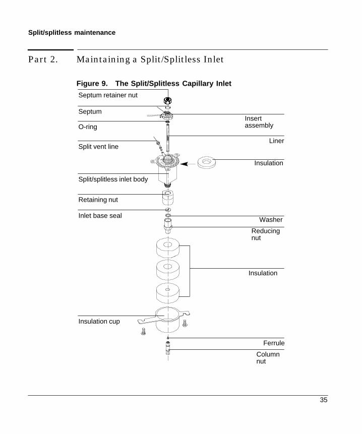
Figure 9. The Split/Splitless Capillary Inlet
Septum retainer nut
SeptumInsertassemblyO-ring
Liner
Split/splitless inlet body
Insulation
Retaining nut
Inlet base sealWasher
Reducingnut
Insulation
Insulation cup
Ferrule
Columnnut
Split vent line

36
Split/splitless maintenance
Changing septa
If a septum leaks, you will see symptoms such as longer or shiftingretention times, loss of response, and/or loss of column head pressure.Additionally, signal noise will increase.
The useful lifetime of septa depends upon injection frequency and needlequality; burrs, sharp edges, rough surfaces, or a blunt end on the needledecrease septum lifetime. When the instrument is in steady use, dailyseptum replacement is recommended.
The type of septa you use will depend on your chromatography needs.You can order septa directly from Hewlett-Packard; refer to theAnalytical Columns and Supplies Catalog for ordering information.
Table 6. Recommended Septa for the Split/Splitless Inlet
Description HP part number
11-mm septum, low-bleed red 5181-1263
11-mm septum with partial through-hole, low-bleed red 5181-3383
11-mm septum, low-bleed gray 5080-8896
Merlin microseal septum (see page 170) 5181-8815
11-mm high-temperature silicon septum (350EC andhigher)
5182-0739
Be careful! The oven and/or inlet may be hot enough to cause burns.WARNING

37
Split/splitless maintenance
Procedure: Changing the septum
Materials needed:
- Gloves (if inlet is hot)- New septum—refer to Table 6 on page 36 for part numbers- Septum nut wrench (HP part no. 19251-00100)- A nonmetallic (plastic or wood) tool with a sharp tip to remove
septum from inlet- 0- or 00-grade steel wool (optional)- Forceps or tweezers- Compressed, filtered, dry air or nitrogen (optional)
1. Complete the following preliminary steps:- If you have entered parameters that you do not want to lose, store
them as a method.- Cool the oven to room temperature and then turn the oven off.- Turn off the detector.- Cool the inlet to room temperature.- Turn the inlet pressure off.- If the inlet is hot, wear gloves to protect your hands from burns.
2. Remove the septum retainer nut, using the wrench if the nut ishot or sticks. Remove the old septum.
If the septum sticks, usethe sharp-tipped tool toremove it. Take care notto gouge the metalaround the septum, andremove all pieces of theold septum.
Septum retainer nut
Septum
38
Split/splitless maintenance
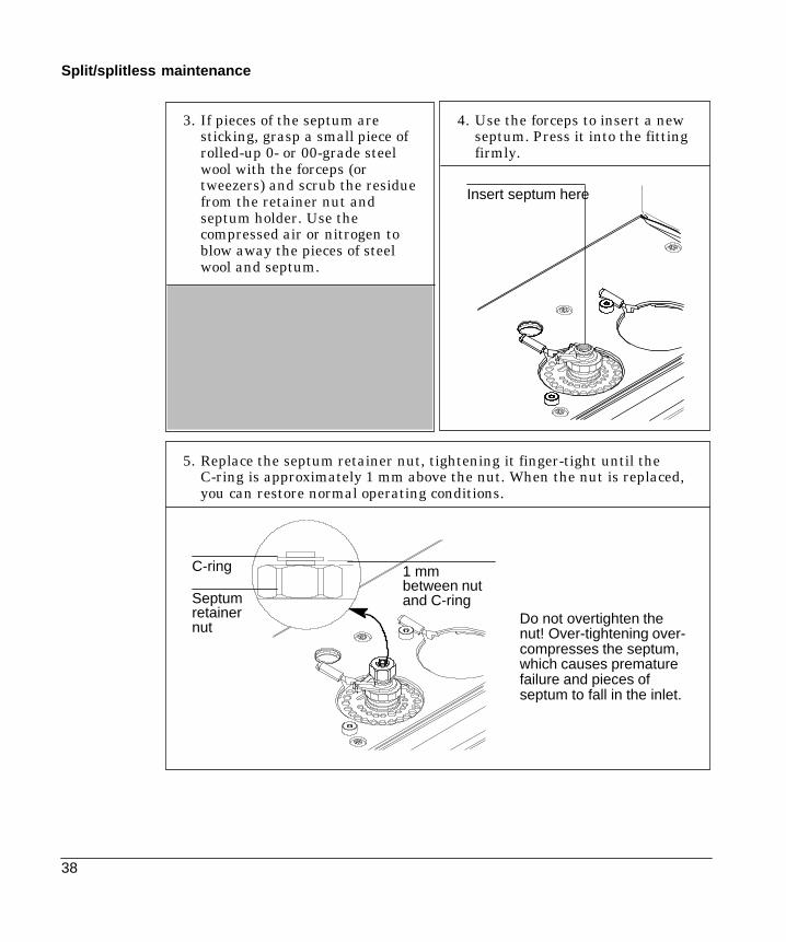
3. If pieces of the septum aresticking, grasp a small piece ofrolled-up 0- or 00-grade steelwool with the forceps (ortweezers) and scrub the residuefrom the retainer nut andseptum holder. Use thecompressed air or nitrogen toblow away the pieces of steelwool and septum.
4. Use the forceps to insert a newseptum. Press it into the fittingfirmly.
5. Replace the septum retainer nut, tightening it finger-tight until theC-ring is approximately 1 mm above the nut. When the nut is replaced,you can restore normal operating conditions.
Do not overtighten thenut! Over-tightening over-compresses the septum,which causes prematurefailure and pieces ofseptum to fall in the inlet.
Insert septum here
1 mmbetween nutand C-ring
C-ring
Septumretainernut

39
Split/splitless maintenance
Changing the O-ring
You will need to change the O-ring each time you change the liner, or ifit wears out and becomes a source of leaks in the inlet. To determine ifthe O-ring leaks, run the leak test for the split/splitless inlet.
O-rings contain plasticizers that give them elasticity. The O-ring sealsthe top of the inlet, the inlet base, and the liner. However, at hightemperatures the plasticizers bake out, and the O-rings become hard andare no longer able to create a seal (this is referred to as “taking a set”).
Figure 10. Cross Section of Inlet, Liner, and O-ring.
Liner
Inletbase
O-ring
Liner
O-ring
Inletbase
New O-ring WornO-ring
40
Split/splitless maintenance
If you regularly operate the inlet at high temperatures, you may want touse graphite O-rings. Although they have a longer life-time, they too willeventually take a set. Refer to the table below to make sure you areusing the correct O-ring for your inlet.
Table 7. O-Rings for the Split/Splitless Inlet
Description HP Part Number
Viton O-ring for temperatures up to 350EC 5181-4182
Graphite O-ring for split liner (temperatures above350EC)
5180-4168
Graphite O-ring for splitless liner (temperatures above350EC)
5180-4173
Be careful! The oven and/or inlet may be hot enough to cause burns. Ifthe inlet is hot, wear gloves to protect your hands.
WARNING

41
Split/splitless maintenance
Procedure: Changing the O-ring
Materials needed:
- Gloves (if inlet is hot)- A new O-ring—refer to Table 7 on page 40- Septum nut wrench (HP part no. 19251-00100)- Forceps or tweezers
1. Complete the following preliminary steps:- If you have entered parameters that you do not want to lose, store
them as a method.- Cool the oven to room temperature and then turn the oven off.- Turn off the detector.- Cool the inlet to room temperature.- Turn the inlet pressure off.- Wear gloves if the inlet is hot to protect your hands from burns.
2. Locate the split/splitless insertnut, and loosen it using thewrench if necessary. Lift itstraight up to avoid chipping orbreaking the liner.
Split/splitlessinsert nut
3. You should see the top of the linerwith the O-ring around it. Usingthe forceps (or tweezers), grasp theliner and pull it out.
Liner andO-ring in inlet

42
Split/splitless maintenance
4. Replace the old O-ring with anew one.
5. Using the forceps, return the linerto the inlet, replace the insertassembly nut, and use the wrenchto tighten the nut just to snugness.
Slide new O-ring onto the liner
6. Restore the GC to normal operating conditions.

43
Split/splitless maintenance
Replacing the inlet base seal
You must replace the inlet base seal whenever you loosen or remove thereducing nut. In addition, chromatographic symptoms such as ghostpeaks indicate that the inlet base seal is dirty and should be replaced.
Two types of inlet base seals are available:
- Gold-plated seal, HP part number 18740-20885
- Stainless steel seal, HP part number 18740-20880
You change the inlet base seal from inside the oven, so you must removethe column. If you are unfamiliar with column installation and removal,see the “Columns and Traps” chapter in the General Informationvolume.
Be careful! The oven and/or inlet may be hot enough to cause burns.WARNING

44
Split/splitless maintenance
Procedure: Replacing the inlet base seal
Materials needed:
- Clean, lint-free, non-nylon gloves (must wear when handling seal)- A new seal (see page 43 for part numbers)- A new washer (HP part no. 5061-5869)- 1/4-in. wrench (for column)- 1/2-in. wrench
2. Remove the column from the inlet. Cap the open end of the column toprevent contamination. If an insulation cup is installed around the base ofthe inlet, remove it.
1. Complete the following preliminary steps:- If you have entered parameters that you do not want to lose, store
them as a method.- Cool the oven to room temperature and then turn the oven off.- Turn off the detector.- Cool the inlet to room temperature.- Turn the inlet pressure off.
Disconnected,capped column
Reducing nut
45
Split/splitless maintenance
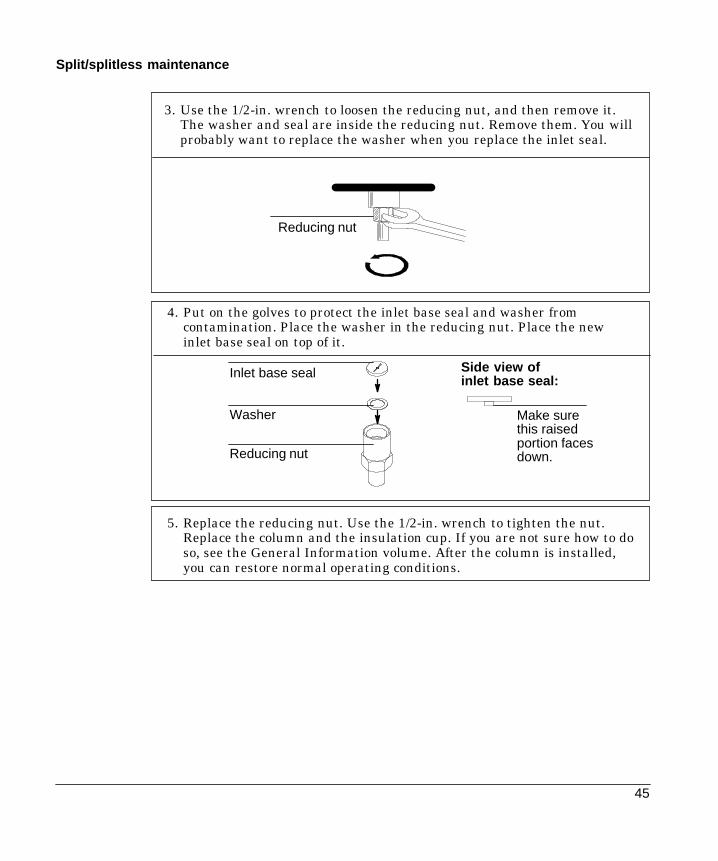
3. Use the 1/2-in. wrench to loosen the reducing nut, and then remove it.The washer and seal are inside the reducing nut. Remove them. You willprobably want to replace the washer when you replace the inlet seal.
4. Put on the golves to protect the inlet base seal and washer fromcontamination. Place the washer in the reducing nut. Place the newinlet base seal on top of it.
Inlet base seal
Washer
Reducing nut
Side view ofinlet base seal:
Make surethis raisedportion facesdown.
Reducing nut
5. Replace the reducing nut. Use the 1/2-in. wrench to tighten the nut.Replace the column and the insulation cup. If you are not sure how to doso, see the General Information volume. After the column is installed,you can restore normal operating conditions.

46
Split/splitless maintenance
Procedure: Leak testing the gas plumbing
Leaks in the gas plumbing can affect chromatographic resultsdramatically. The following procedure checks the flow system up to butnot including the inlet flow manifold. If this portion of the system provesto be leak-free, refer to the next procedure to check the inlet and inletmanifold.
Liquid leak detectors are not recommended, especially in areas wherecleanliness is very important.
If you do use leak detection fluid, immediately rinse the fluid off toremove the soapy film.
To avoid a potential shock hazard when using liquid detection fluid, turnthe GC off and disconnect the main power cord. Be careful not to spillleak solution on electrical leads, especially the detector heater leads.
Materials needed:
- Electronic leak detector capable of detecting your gas type or liquidleak detection fluid. If you use leak detection fluid, remove excessfluid when you have completed the test.
- Two 7/16-in. wrenches
1. Using the leak detector, checkeach connection you have madefor leaks.
2. Correct leaks by tightening theconnections. Retest theconnections; continue tighteninguntil all connections areleak-free.
WARNING

47
Split/splitless maintenance
Procedure: Leak testing an EPC split/splitless inlet
There are numerous places in the inlet that can leak. This procedure letsyou determine, in general, if there is an unacceptable leak in the inlet.If the inlet is leaking, you should use an electronic leak detector topinpoint the component that is leaking.
Be careful! The oven and/or inlet may be hot enough to cause burns.
Materials needed:
- No-hole ferrule- 7/16-in. wrench- Gloves (if the inlet is hot)- Septum nut wrench (HP part no. 19251-00100)- 9/16-in. wrench- 1/4-in. SWAGELOK cap- Bubble flow meter
1. Complete the following preliminary steps:- If you have entered parameters that you do not want to lose, store
them as a method.- Cool the oven to room temperature and then turn it off.- When the oven is cool, turn off the inlet pressure.- Remove the column, if one is installed, and plug the column fitting
with the column nut and a no-hole ferrule.- Remove the old septum and replace it with a new one. For instructions,
see “Changing Septa” on page 36.- Inspect the O-ring and replace it if it is hard and brittle or cracked. See
page 40 for instructions.
WARNING

48
Split/splitless maintenance
2. Cap the septum purge fitting with a 1/4-in. SWAGELOK cap.
3. Set the oven to its normal operating temperature. Set the inlet to itsnormal operating temperature. Enter a pressure setpoint between 20 and25 psi, or enter your normal operating pressure if it is greater. Make surethat the pressure at the gas supply is at least 10 psi higher than the inletpressure.
Mode SplitTemp 150 150Pressure 0.0 24.0<Split ratio 25.0Split flow 0.0Total flow 0.0 OffGas saver Off
FRONT INLET (S/SL)Press [FrontInlet] or [BackInlet]
Capped septumpurge fitting

49
Split/splitless maintenance
Mode SplitTemp 150 150Pressure 24.2 24.0<Split ratio 25.0Split flow 0.0Total flow 60.0 60.0Gas saver Off
FRONT INLET (S/SL)Press [FrontInlet] or [BackInlet]
4. Set the total flow to 60 ml/min. Wait a few moments for the pressureand flow to equilibrate.
The GC mayexceed thepressure setpointslightly whileequilibrating.
5. Verify that the flow is actually 60 ml/min by measuring the flow rate atthe split purge vent on the manifold. Use a bubble flow meter tomeasure the flow.
Measure flow at this fitting
50
Split/splitless maintenance
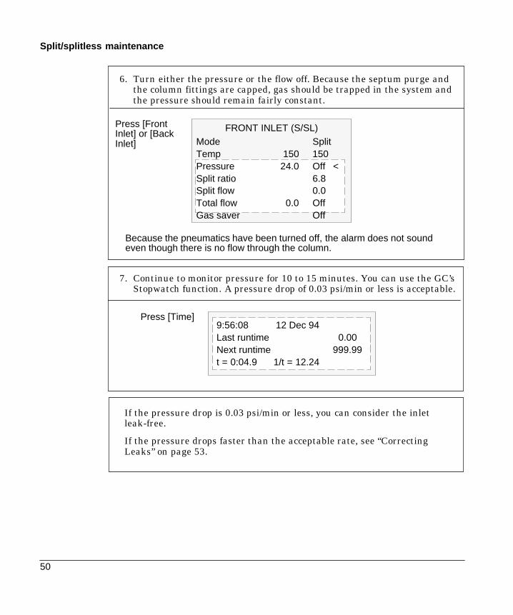
6. Turn either the pressure or the flow off. Because the septum purge andthe column fittings are capped, gas should be trapped in the system andthe pressure should remain fairly constant.
Because the pneumatics have been turned off, the alarm does not soundeven though there is no flow through the column.
Mode SplitTemp 150 150Pressure 24.0 Off <Split ratio 6.8Split flow 0.0Total flow 0.0 OffGas saver Off
FRONT INLET (S/SL)Press [FrontInlet] or [BackInlet]
7. Continue to monitor pressure for 10 to 15 minutes. You can use the GC’sStopwatch function. A pressure drop of 0.03 psi/min or less is acceptable.
If the pressure drop is 0.03 psi/min or less, you can consider the inletleak-free.
If the pressure drops faster than the acceptable rate, see “CorrectingLeaks” on page 53.
9:56:08 12 Dec 94Last runtime 0.00Next runtime 999.99t = 0:04.9 1/t = 12.24
Press [Time]

51
Split/splitless maintenance
Procedure: Leak testing a nonEPC split/splitless inlet
There are numerous places in the inlet that can leak. This procedure letsyou determine, in general, if there is an unacceptable leak in the inlet.If the inlet is leaking, you should use an electronic leak detector topinpoint the component that is leaking.
Be careful! The oven and/or inlet may be hot enough to cause burns.
Materials needed:
- No-hole ferrule- 7/16-in. wrench- Gloves (if the inlet is hot)- Septum nut wrench (HP part no. 19251-00100)- 9/16-in. wrench- 1/8-in. SWAGELOK cap- Bubble flow meter
1. Complete the following preliminary steps:
- If you have entered parameters that you do not want to lose,store them as a method.
- Cool the oven to room temperature and then turn it off.- When the oven is cool, turn off the inlet pressure.- Remove the column, if one is installed, and plug the column
fitting with the column nut and a no-hole ferrule.- Remove the old septum and replace it with a new one. For
instructions on changing septa, see page 36.- Inspect the O-ring and replace it if it is hard and brittle or
cracked. See page 40 for instructions.2. Cap the purge vent with a 1/8-in. SWAGELOK cap.
3. Set the oven to its normal operating temperature.
4. Set the inlet to its normal operating temperature. Make sure that thepressure at the initial gas supply is at least 35 psi.
WARNING

52
Split/splitless maintenance
5. Set the inlet pressure between 20 and 25 psi, or to your normaloperating pressure, if it is higher. Set the split flow to 60 ml/min.Wait a few moments for the pressure and flow to equilibrate.
6. Verify that the septum purge is off by using a bubble flow meter.
7. Turn off flow to the inlet by turning off the carrier gas at the flowcontroller. Then, adjust the back pressure regulator clock-wise and additional 1/4 turn.
Observe the column pressure for approximately 15 minutes. If thepressure remains between 19 and 20 psi, or if the pressure drop is0.03 psi/min or less, you can consider the inlet leak-free.
If the pressure drops faster than the acceptable rate, go to the nextsection, “Correcting Leaks.”

53
Split/splitless maintenance
Procedure: Correcting leaks
Materials needed:
- Electronic leak detector- Tools to tighten connections
1. Use the electronic leak detector to check all areas of the inlet that arepotential sources of a leak. Potential leak areas are:
- The capped purge vent- The plugged column connection- The septum and/or septum nut- The area where the gas lines are plumbed to the inlet- The O-ring- The O-ring nut- The inlet base seal
2. Correct leaks using the correct size wrench to tighten connections.You may need to repeat the leak test again to check for leaks.
If the pressure drop is now 0.03 psi/min or less, you can consider theinlet system leak-free.
If the pressure drops faster than this, continue to search for leaksand repeat the pressure test. If all fittings appear to be leak free, butthe inlet system is still losing too much pressure, you may need toreplace the inlet manifold. Contact your Hewlett-Packard servicerepresentative.

54
Split/splitless maintenance
Procedure: Cleaning the inlet
It is unlikely that the inlet will frequently require the thorough cleaningthat this procedure presents; however, deposits from injected samplesoccasionally build up inside the split/splitless inlet. Before cleaning theinlet, replace dirty column liners and inserts with clean ones. If changingthem does not correct the problems, then clean the inlet.
Materials needed:
- Cleaning brushes—The FID cleaning kit contains appropriatebrushes(HP part no. 9301-0985)
- Solvent that will clean the type of deposits in your inlet- Compressed, filtered, dry air or nitrogen
1. Complete the following preliminary steps:- If you have entered parameters that you do not want to lose, store
them as a method.- Cool the heated zones to room temperature. Turn them off when they
cool.- Turn off all flows to the inlet at the initial gas supply.- Turn off the GC and unplug it.- Remove the liner.- Remove the column and the column liner. See the “Columns and
Traps” chapter in the General Information volume.- Remove the inlet base seal. See page 43 for instructions.
2. Using a suitable light source, illuminate the inside of the inlet frominside the oven and look for signs of contamination or deposits. Insertthe brush into the inlet. Scrub the interior walls of the inlet vigorouslyto remove all deposits.
55
Split/splitless maintenance
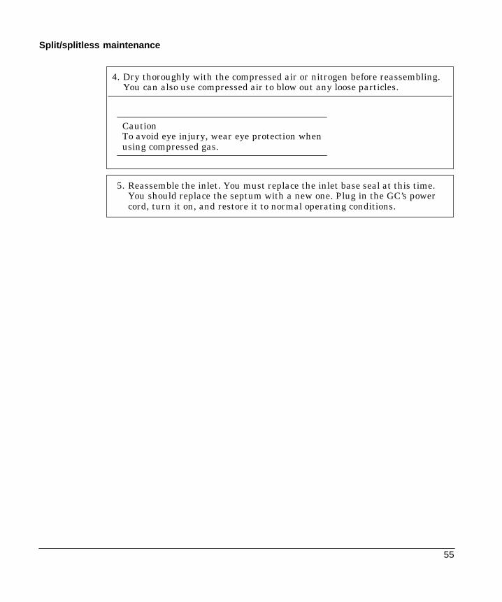
4. Dry thoroughly with the compressed air or nitrogen before reassembling.You can also use compressed air to blow out any loose particles.
CautionTo avoid eye injury, wear eye protection whenusing compressed gas.
5. Reassemble the inlet. You must replace the inlet base seal at this time.You should replace the septum with a new one. Plug in the GC’s powercord, turn it on, and restore it to normal operating conditions.
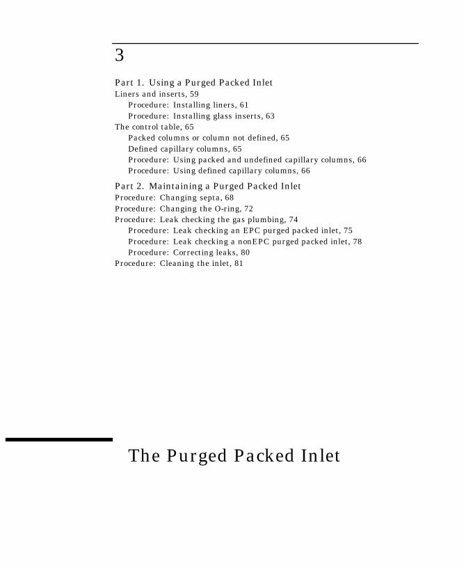
3
The Purged Packed Inlet
Part 1. Using a Purged Packed InletLiners and inserts, 59
Procedure: Installing liners, 61Procedure: Installing glass inserts, 63
The control table, 65Packed columns or column not defined, 65Defined capillary columns, 65Procedure: Using packed and undefined capillary columns, 66Procedure: Using defined capillary columns, 66
Part 2. Maintaining a Purged Packed InletProcedure: Changing septa, 68Procedure: Changing the O-ring, 72Procedure: Leak checking the gas plumbing, 74
Procedure: Leak checking an EPC purged packed inlet, 75Procedure: Leak checking a nonEPC purged packed inlet, 78Procedure: Correcting leaks, 80
Procedure: Cleaning the inlet, 81

58
Chapter 3.The Purged Packed Inlet
Part 1. Using a Purged Packed Inlet
This inlet is used with packed columns when high-efficiency separationsare not required. It can also be used with wide-bore capillary columns,provided that flows greater than 10 mL/min are acceptable.
If a capillary column is used and the column is defined, the inlet ispressure-controlled. If the column is not defined (packed columns andundefined capillary columns), the inlet is flow-controlled.
Figure 11. Packed Column Inlet with Electronic Pneumatics Control
Purge VentFlow
Septum holder
Flow-controlled mode (recommended forpacked columns)
Flowsensor
Proportionalvalve
FS PS
Pressuresensor
SPR
Total flowcontrol loop
To columnand detec-
tor
Pressure-controlled mode (recommended for capillary columns)
Purge VentFlow
Septum holderFlowsensor
Proportionalvalve
FS PS
Pressuresensor
SPR
To columnand detector
Inlet pressurecontrol loop
Septum purgeregulator (not ad-
justable)
Septum purgeregulator (notadjustable)
Flowlimiting
frit
Flowlimiting
frit

59
Purged packed operation
Liners and inserts
Liners. Your choice of liner depends on the type of column you are using.Liners are available for use with wide-bore capillary, 1/4-in. packed, or1/8-in. packed columns. The liner functions as an adapter so thatcolumns can be connected to the inlet. Installation instructions are onpage 61.
Inserts. Glass inserts are often used with metal liners to reducereactivity and trap nonvolatile residues. They are always used withcapillary columns. Inserts are installed from the top of the inlet andshould be installed before the column. Installation instructions are onpage 63.
The purged packed inlet is shipped with a liner and insert for use withcapillary columns (see Table 8.) If you are using packed columns, consultTable 9.
Table 8. Liner and Insert for Wide-Bore Capillary Columns(Narrow-bore capillary columns are not recommended for use with this inlet.)
Column type Liner Insert
530 mm or320 mm
19244-80540
1/4-in nut
1/4-inVespel ferrule
C ill
5080-8732 or5181-3382*
Capillaryliner
*Deactivated

60
Purged packed operation
Table 9. Liner and Insert for Packed Columns
Column Type Liner Insert
1/8-in. metal 1/8-in. stainless steel19243-80510 None
19243-80530 5080-8732 or5181-3382*
1/4-in. metal 1/4-in. stainless steel19243-80520 none
19243-80540 5080-8732 or5181-3382*
1/4-in. glass No liner required.Column endfunctions as liner.Can also use 1/4-in.metal liner.
Not applicable
*Deactivated
1/4-in.nut
1/4-in. Vespelferrule
1/8-in. or 1/4-in.stainless steelliner
1/4- or 1/8-inch liner(stainless steel)
Insert
61
Purged packed operation
Procedure: Installing liners
Use these instructions for installing all liner types. Graphitized Vespelferrules are recommended because metal ferrules tend to lockpermanently onto the liner. If a leak develops when using metal ferrules,you must replace the entire liner.
Materials needed:
- Liner, brass nut, and ferrule (see Table 8 or Table 9)- Lint-free cloth- Methanol- 9/16-in. wrench
1. Press [Oven] and set the oven to 35EC. When the temperaturereaches setpoint, turn the oven off. Press [Front Inlet] or [Back Inlet]and turn off the inlet temperature and pressure or flow.
Be careful. The oven and inlet fittings may be hot enough to causeburns.
2. Clean the end of the liner with a lint-free cloth to removecontamination such as fingerprints. Use methanol as a solvent.
3. Place a brass nut and graphitized Vespel ferrule on the liner.
4. Open the oven door and locate the inlet base. Insert the liner straightinto the inlet base as far as possible.
5. Hold the liner in this position and tighten the nut finger tight.
6. Use a wrench to tighten the nut an additional 1/4 turn.
7. Install the column.
8. Establish a flow of carrier gas through the inlet, and heat the ovenand inlet to operating temperatures. Allow these to cool, and thenretighten the fittings.
WARNING
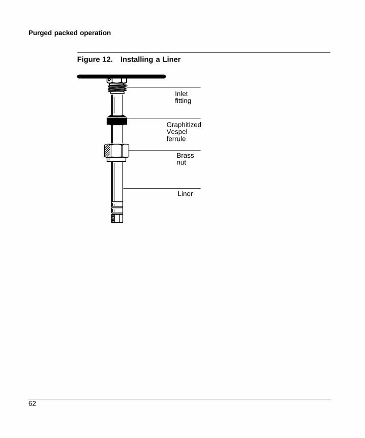
62
Purged packed operation
Figure 12. Installing a Liner
Inletfitting
GraphitizedVespelferrule
Brassnut
Liner
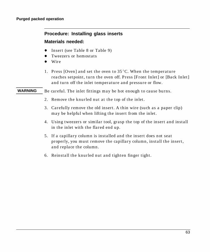
63
Purged packed operation
Procedure: Installing glass inserts
Materials needed:
- Insert (see Table 8 or Table 9)- Tweezers or hemostats- Wire
1. Press [Oven] and set the oven to 35EC. When the temperaturereaches setpoint, turn the oven off. Press [Front Inlet] or [Back Inlet]and turn off the inlet temperature and pressure or flow.
Be careful. The inlet fittings may be hot enough to cause burns.
2. Remove the knurled nut at the top of the inlet.
3. Carefully remove the old insert. A thin wire (such as a paper clip)may be helpful when lifting the insert from the inlet.
4. Using tweezers or similar tool, grasp the top of the insert and installin the inlet with the flared end up.
5. If a capillary column is installed and the insert does not seatproperly, you must remove the capillary column, install the insert,and replace the column.
6. Reinstall the knurled nut and tighten finger tight.
WARNING

64
Purged packed operation
Figure 13. Installing a Glass Insert in a Purged Packed Inlet
Knurled nut
Insert

65
Purged packed operation
The control table
Packed columns or column not defined
FRONT INLET (PP)Temp 24 OffPressure 0.0Tot flow 0.0 Off
(The inlet)
COLUMN 1 (He)Dimensions unknownPressure 0.0Flow 0.0 OffMode: Constant flow
(The column)
Temp The setpoint and actual temperature values.
Pressure The actual pressure (in psi, bar, or kPa) supplied to the inlet.You cannot enter a setpoint here.
Tot flow Enter your setpoint here, actual value is displayed. Inlet ismass flow controlled.
Defined capillary columns
FRONT INLET (PP)Temp 24 OffPressure 0.0 OffTot flow 0.0
(column defined)
Temp The setpoint and actual temperature values
Pressure Inlet is pressure controlled. Enter your setpoint here (in psi,bar, or kPa) and actual value is displayed.
Tot flow The actual total flow to the inlet. This is a reported value, nota setpoint.
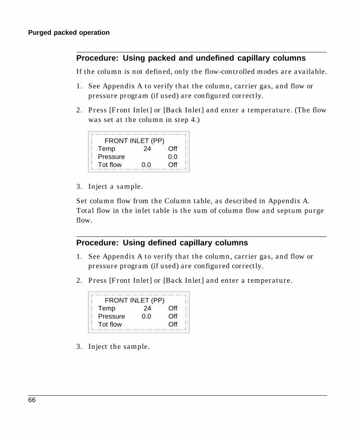
66
Purged packed operation
Procedure: Using packed and undefined capillary columns
If the column is not defined, only the flow-controlled modes are available.
1. See Appendix A to verify that the column, carrier gas, and flow orpressure program (if used) are configured correctly.
2. Press [Front Inlet] or [Back Inlet] and enter a temperature. (The flowwas set at the column in step 4.)
FRONT INLET (PP)Temp 24 OffPressure 0.0Tot flow 0.0 Off
3. Inject a sample.
Set column flow from the Column table, as described in Appendix A.Total flow in the inlet table is the sum of column flow and septum purgeflow.
Procedure: Using defined capillary columns
1. See Appendix A to verify that the column, carrier gas, and flow orpressure program (if used) are configured correctly.
2. Press [Front Inlet] or [Back Inlet] and enter a temperature.
FRONT INLET (PP)Temp 24 OffPressure 0.0 OffTot flow Off
3. Inject the sample.
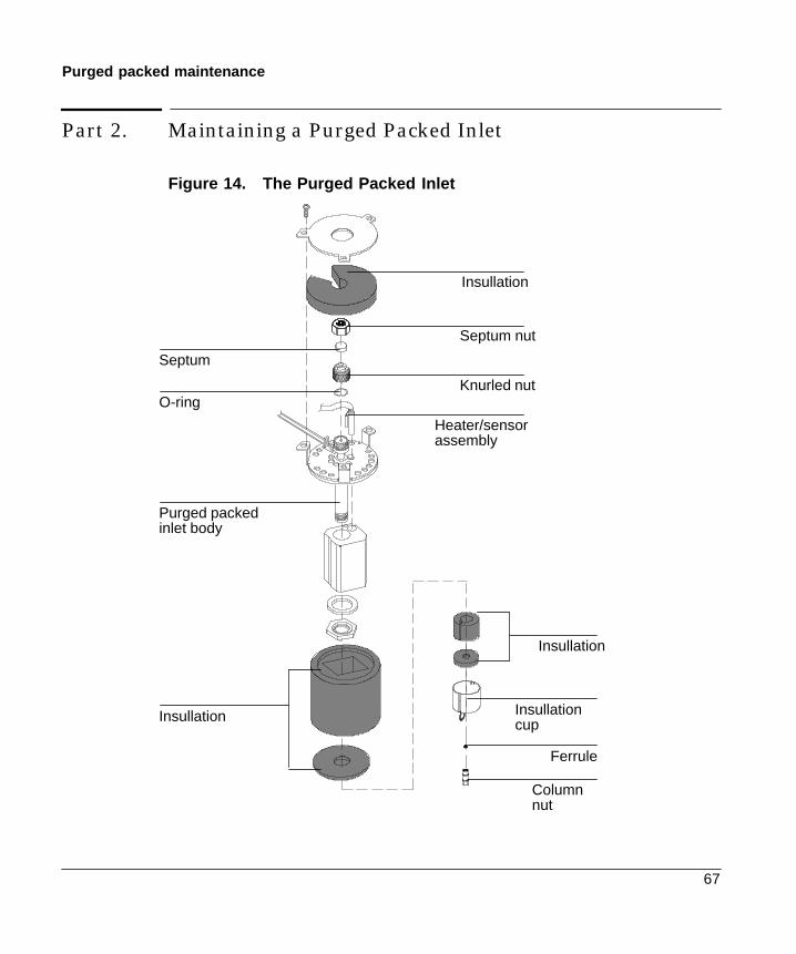
67
Purged packed maintenance
Part 2. Maintaining a Purged Packed Inlet
Figure 14. The Purged Packed Inlet
Septum nut
Septum
Knurled nutO-ring
Insullation
Purged packedinlet body
Insullation
Insullation
Insullationcup
Ferrule
Columnnut
Heater/sensorassembly

68
Purged packed maintenance
Procedure: Changing septa
If the septum leaks, you will see symptoms such as longer or shiftingretention times, loss of response, and/or loss of column head pressure.Additionally, the detector signal will become increasingly noisy.
The useful lifetime of septa is determined by injection frequency andneedle quality; burrs, sharp edges, rough surfaces, or a blunt end on theneedle decrease septum lifetime. When the instrument is used regularly,daily septum replacement is recommended.
The type of septa you use will depend on your chromatography needs.You can order septa directly from Hewlett-Packard; see the AnalyticalColumns and Supplies Catalog for ordering information.
Table 10. Recommended Septa for the Purged Packed Inlet
Description HP Part Number
11-mm septum, low-bleed red 5181-1263
11-mm septum with partial through-hole, low-bleed red 5181-3383
11-mm septum, low-bleed gray 5080-8896
Merlin microseal septum 5181-8815
11-mm high-temperature silicon septum (350EC andhigher)
5182-0739
Be careful! The oven and/or inlet may be hot enough to cause burns.
Column flow is interrupted while changing septa; since columns may bedamaged at elevated temperatures without carrier flow, cool the oven toroom temperature before proceeding.
WARNING
Caution
69
Purged packed maintenance
Materials needed:
- Gloves (if the inlet is hot)- New septum—see Table 10 on page 68 for part numbers- Septum nut wrench (HP part no. 19251-00100)- A nonmetallic (plastic or wood) tool with a sharp tip to remove
septum from inlet- 0- or 00-grade steel wool (optional)- Forceps or tweezers- Compressed, filtered, dry air or nitrogen (optional)
1. Complete the following preliminary steps:- If you have entered parameters that you do not want to lose, store
them as a method.- Cool the oven to room temperature and then turn the oven off.- Turn off the detector.- Cool the inlet to room temperature.- Turn the inlet pressure off.
CautionIf you are using packed columns, decrease head pressureto prevent a sudden release of inlet pressure from blowingthe packing out of the column.
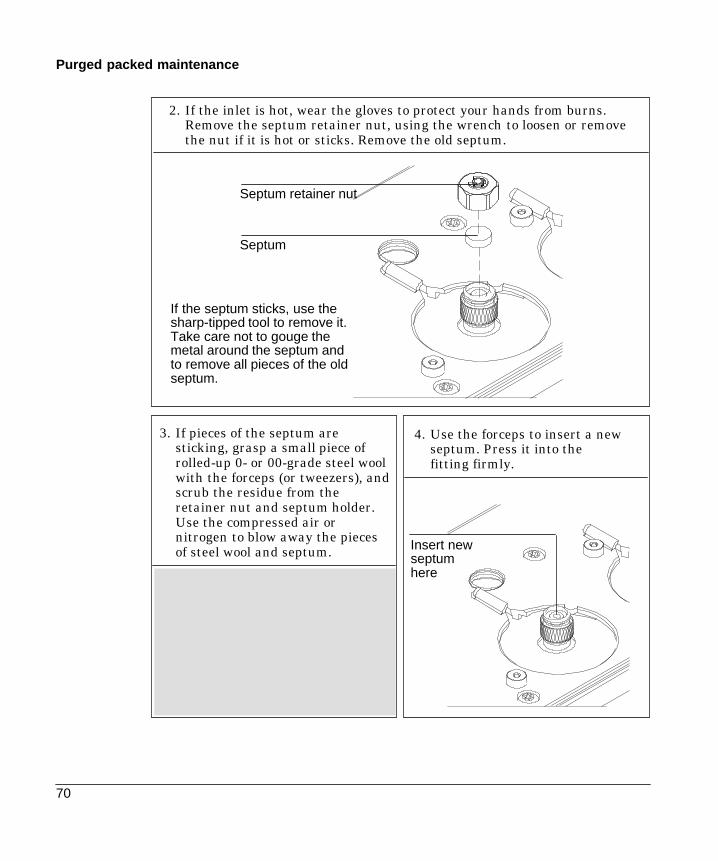
70
Purged packed maintenance
2. If the inlet is hot, wear the gloves to protect your hands from burns.Remove the septum retainer nut, using the wrench to loosen or removethe nut if it is hot or sticks. Remove the old septum.
If the septum sticks, use thesharp-tipped tool to remove it.Take care not to gouge themetal around the septum andto remove all pieces of the oldseptum.
Septum retainer nut
Septum
4. Use the forceps to insert a newseptum. Press it into thefitting firmly.
3. If pieces of the septum aresticking, grasp a small piece ofrolled-up 0- or 00-grade steel woolwith the forceps (or tweezers), andscrub the residue from theretainer nut and septum holder.Use the compressed air ornitrogen to blow away the piecesof steel wool and septum. Insert new
septumhere

71
Purged packed maintenance
Do not overtighten the nut!Over-tightening over-compresses the septum,which could causepremature failure andpieces of septum tocontaminate the inlet.
5. Replace the septum retainer nut, tightening it finger-tight until theC-ring is approximately 1 mm above the nut. When the nut is tightened,you can restore normal operating conditions.
C-ring
Septumretainer nut
1 mm betweennut and C-ring

72
Purged packed maintenance
Procedure: Changing the O-ring
You will need to change the O-ring periodically because it wears out andbecomes a source of leaks in the inlet. To determine if the O-ring leaks,perform the leak test presented later in this chapter.
O-rings contain plasticizers that give them elasticity. The O-ring sealsthe top of the inlet and the inlet base. However, at high temperaturesthe plasticizers bake out, and the O-rings become hard and are unable tocreate a seal (this is referred to as “taking a set”). If you operate the inletat high temperatures, you will probably need to replace the O-ringfrequently.
Be careful! The oven and/or inlet may be hot enough to cause burns.If the inlet is hot, be sure to wear gloves to protect your hands.
Materials needed:
- Gloves (if the inlet is hot)- A new Viton O-ring (HP part no. 5080-8898)- Septum nut wrench (HP part no. 19251-00100)- Forceps or tweezers (optional)
1. Complete the following preliminary steps:- If you have entered parameters that you do not want to lose, store
them as a method.- Cool the oven to room temperature and then turn the oven off.- Turn off the detector.- Cool the inlet to room temperature.- Turn the inlet pressure off.
CautionIf you are using packed columns, decrease headpressure to prevent a sudden release of inlet pressurefrom blowing the packing out of the column.
WARNING

73
Purged packed maintenance
2. If the inlet is hot, use the septumnut wrench. Loosen the knurlednut completely. Pull up on thenut to remove the top portion ofthe inlet.
Knurled nut
3. The O-ring will be visible.Remove the old O-ring. You mayneed to use forceps to grab it.Using the tweezers, insert thenew O-ring.
O-ring
Pulling up on theknurled nutremoves entire topof inlet.
4. Replace the top portion of the inlet and tighten the knurled nut until youcannot tighten it further. Restore the GC to normal operating conditions.

74
Purged packed maintenance
Procedure: Leak testing the gas plumbing
Leaks in the gas plumbing system can affect chromatographic resultsdramatically. The following procedure checks the flow system up to butnot including the inlet flow manifold. If this portion of the system provesto be leak-free, refer to the next procedure to check the inlet and inletmanifold.
Liquid leak detectors are not recommended, especially in areas wherecleanliness is very important.
If you do use leak detection fluid, immediately rinse the fluid off toremove the soapy film.
To avoid a potential shock hazard when using liquid detection fluid, turnthe GC off and disconnect the main power cord. Be careful not to spillleak solution on electrical leads, especially the detector heater leads.
Materials needed:
- Electronic leak detector or liquid leak detection fluid. If you use leakdetection fluid, wipe off excess fluid when you have completed thetest.
- Two 7/16-in. wrenches
1. Using the leak detector, checkeach connection you have madefor leaks.
2. Correct leaks by tightening theconnections. Retest theconnections; continue tighteninguntil all connections areleak-free.
WARNING

75
Purged packed maintenance
Procedure: Leak testing an EPC purged packed inlet
This procedure allows you to determine if the inlet is leaking. It isrecommended that you leak test the inlet at your normal operatingtemperature since the O-ring may leak if it is cooled to ambient.
Materials needed:
- Gloves (if the inlet is hot)- Septum nut wrench (HP part no. 19251-00100)
If you are using capillary columns:
- No-hole ferrule- 7/16-in. wrench
If you are using packed columns:
- Solid Vespel plug- 9/16-in. wrench
1. Complete the following preliminary steps:- If you have entered parameters that you do not want to lose, store
them as a method.- Cool the oven to room temperature and then turn it off.- When the oven is cool, turn off the inlet pressure.- Remove the column, if one is installed, and cap the column fitting.
If you are using capillary columns, insert a no-hole ferrule in thecolumn nut to create a plug.If you are using packed columns, use the Vespel plug.
- Remove the old septum and replace it with a new one. For instructionson changing septa, see “Changing Septa” on page 68.
- Inspect the O-ring and replace it if it is hard and brittle or cracked. Seepage 72 for instructions on changing the O-ring.
- Make sure that the pressure at the initial gas source is at least 35 psi.

76
Purged packed maintenance
2. Set the inlet to its normal operating temperature.
Temp 150 150 <Pressure 0.0 OffTotal flow 0.0
FRONT INLET (pp)Press [FrontInlet] or [BackInlet]
3. Set the inlet pressure between 20 and 25 psi.
Temp 24 OffPressure 0.0 24.0<Total flow 0.0
FRONT INLET (pp)Press [FrontInlet] or [BackInlet]
4. Wait a few minutes for the pressure to equilibrate.
The GC mayexceed thepressure setpointslightly whileequilibrating.
Temp 24 OffPressure 24.2 24.0<Total flow 0
FRONT INLET (pp)Press [FrontInlet] or [BackInlet]
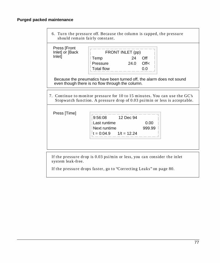
77
Purged packed maintenance
7. Continue to monitor pressure for 10 to 15 minutes. You can use the GC’sStopwatch function. A pressure drop of 0.03 psi/min or less is acceptable.
6. Turn the pressure off. Because the column is capped, the pressureshould remain fairly constant.
Because the pneumatics have been turned off, the alarm does not soundeven though there is no flow through the column.
Temp 24 OffPressure 24.0 Off<Total flow 0.0
FRONT INLET (pp)Press [FrontInlet] or [BackInlet]
9:56:08 12 Dec 94Last runtime 0.00Next runtime 999.99t = 0:04.9 1/t = 12.24
Press [Time]
If the pressure drop is 0.03 psi/min or less, you can consider the inletsystem leak-free.
If the pressure drops faster, go to “Correcting Leaks” on page 80.
78
Purged packed maintenance
Procedure: Leak testing a nonEPC purged packed inlet
This procedure allows you to determine if the inlet leaks. It isrecommended that you leak test the inlet at your normal operatingtemperature since the O-ring is likely to leak if it is cooled to ambient.
Materials needed:
- Gloves (if the inlet is hot)- Septum nut wrench (HP part no. 19251-00100)- 1/8 in. SWAGELOK cap (HP part no. 5180-4120)
If you are using capillary columns:
- No-hole ferrule- 7/16-in. wrench
If you are using packed columns:
- Solid Vespel plug- 9/16-in. wrench
1. Complete the following preliminary steps:
- If you have entered parameters that you do not want to lose,store them as a method.
- Cool the oven to room temperature and then turn it off.- When the oven is cool, turn off the inlet pressure.- Remove the column, if one is installed, and cap the column fitting.
If you are using capillary columns, insert a no-hole ferrule inthe column nut and then attach the nut to the fitting.If you are using packed columns, attach the Vespel plug to thefitting.
- Remove the old septum and replace it with a new one. Forinstructions on changing septa, see “Changing Septa” on page 68.
- Inspect the O-ring, and replace it if it is hard and brittle orcracked. See page 72 for instructions on changing the O-ring.

79
Purged packed maintenance
2. Set the inlet to its normal operating temperatures.
3. Cap the septum purge vent with a 1/8-in. SWAGELOK cap.
4. Turn on the gas to the inlet at its source and adjust the supplypressure to 50 psi. Completely open the mass flow controller byturning the knob counterclockwise as far as it can go. Wait 2 minutesto insure equilibrium.
5. Turn off the gas to the inlet at its source. Monitor the pressure for 10to 15 minutes. You can use the GC’s Stopwatch function. A pressuredrop of 0.03/min psi or less is acceptable.
If the pressure drop is 0.03 psi/min or less, you can consider the inletleak-free.
If the pressure drops faster than this, go to “Correcting Leaks” onpage 80.

80
Purged packed maintenance
Procedure: Correcting leaks
Materials needed:
- Electronic leak detector suitable for the gas type- Tools to tighten parts of the inlet that leak (if leaks are detected)
1. Use the leak detector to check all areas of the inlet that are potentialsources of a leak. Potential leak areas are:
- The septum and/or septum nut
- The 1/4-in. ferrule (if a liner is being used)
- The O-ring
- The capped purge vent
- The plugged column connection
- The knurled nut
- The area where the gas line is plumbed to the inlet
If no liner is used, then column must be plugged with 1/4-in.SWAGELOK cap or equivalent
2. Correct leaks using a wrench to tighten loose connections, ifnecessary. You may need to repeat the leak test.
If the pressure drop is now 0.03 psi/min. or less, you can consider theinlet leak-free.
If the pressure drops faster than the acceptable rate, continue tosearch for leaks and repeat the pressure test. If all fittings appear tobe leak free, but the inlet is still losing too much pressure, you mayneed to replace the inlet manifold. Contact your Hewlett-Packardservice representative.
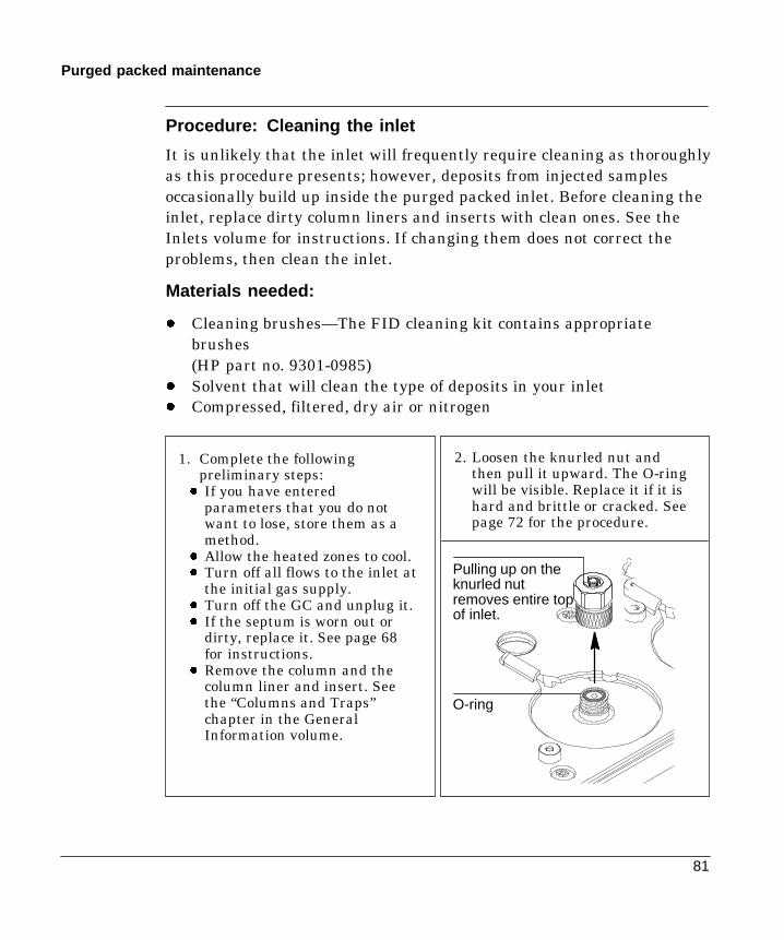
81
Purged packed maintenance
Procedure: Cleaning the inlet
It is unlikely that the inlet will frequently require cleaning as thoroughlyas this procedure presents; however, deposits from injected samplesoccasionally build up inside the purged packed inlet. Before cleaning theinlet, replace dirty column liners and inserts with clean ones. See theInlets volume for instructions. If changing them does not correct theproblems, then clean the inlet.
Materials needed:
- Cleaning brushes—The FID cleaning kit contains appropriatebrushes(HP part no. 9301-0985)
- Solvent that will clean the type of deposits in your inlet- Compressed, filtered, dry air or nitrogen
1. Complete the followingpreliminary steps:
- If you have enteredparameters that you do notwant to lose, store them as amethod.
- Allow the heated zones to cool.- Turn off all flows to the inlet at
the initial gas supply.- Turn off the GC and unplug it.- If the septum is worn out or
dirty, replace it. See page 68for instructions.
- Remove the column and thecolumn liner and insert. Seethe “Columns and Traps”chapter in the GeneralInformation volume.
2. Loosen the knurled nut andthen pull it upward. The O-ringwill be visible. Replace it if it ishard and brittle or cracked. Seepage 72 for the procedure.
O-ring
Pulling up on theknurled nutremoves entire topof inlet.

82
Purged packed maintenance
5. Replace the top of the inlet and tighten the knurled nut. Replace thecolumn (the procedure is in the General Information volume).
3. Using a suitable light source, illuminate the inside of the inlet frominside the oven while looking through the inlet from the top. Ifdeposits are present, they should be visible.
4. Insert the brush into the inlet. Scrub the interior walls of the inletvigorously to remove all deposits. You may need to wet the brush withsolvent. Use a burst of the compressed air or nitrogen to dry the inletand remove loose contaminants.
WARNINGTo avoid eye injury, wear eyeprotection when using compressed gas.
6. Plug in the GC’s power cord, turn it on, and restore it to normaloperating conditions.

4
The Cool On-Column Inlet
Part 1. Using a Cool On-Column InletHardware, 85Automatic or manual injection with septum nut, 87Manual injection with cooling tower duckbill septum, 88Procedure: Changing septum nut or cooling tower and septum, 89
Procedure: Installing an insert, 90Procedure: Check needle-to-column size, 91
Procedure: Manual injection with septum nut, 92Procedure: Manual injection with cooling tower, 93Retention gaps, 94Inlet temperature, 94
CryoBlast (optional), 94Track oven mode, 94Temperature programming mode, 95Cryogenic considerations, 95Setpoint ranges, 95Procedure: Programming temperature, 96
Procedure: Operating the cool on-column inlet, 97
Part 2. Maintaining a Cool On-Column InletCool on-column inlet hardware problems, 100Procedure: Replacing the fused silica syringe needle, 101Procedure: Installing a fused silica needle, 102Changing septa, 103Procedure: Cleaning the inlet, 106Procedure: Leak checking the gas plumbing, 109Procedure: Leak checking a cool on-column inlet, 110Procedure: Correcting leaks, 113
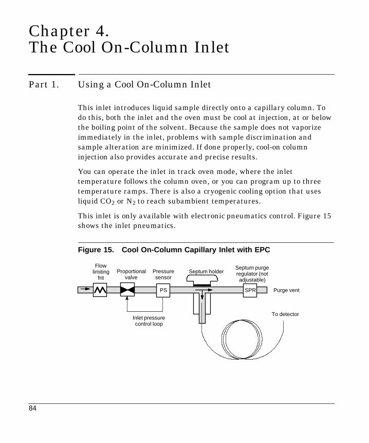
84
Chapter 4.The Cool On-Column Inlet
Part 1. Using a Cool On-Column Inlet
This inlet introduces liquid sample directly onto a capillary column. Todo this, both the inlet and the oven must be cool at injection, at or belowthe boiling point of the solvent. Because the sample does not vaporizeimmediately in the inlet, problems with sample discrimination andsample alteration are minimized. If done properly, cool-on columninjection also provides accurate and precise results.
You can operate the inlet in track oven mode, where the inlettemperature follows the column oven, or you can program up to threetemperature ramps. There is also a cryogenic cooling option that usesliquid CO2 or N2 to reach subambient temperatures.
This inlet is only available with electronic pneumatics control. Figure 15shows the inlet pneumatics.
Figure 15. Cool On-Column Capillary Inlet with EPC
Septum holderProportionalvalve
PS
Pressuresensor
SPR
Inlet pressurecontrol loop
Purge vent
To detector
Septum purgeregulator (notadjustable)
Flowlimiting
frit
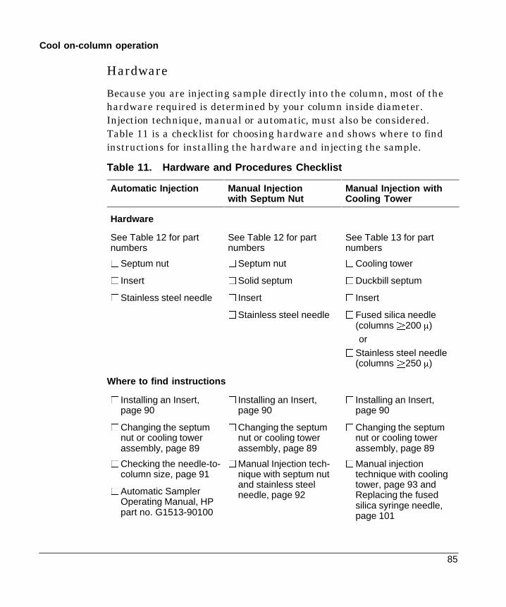
85
Cool on-column operation
Hardware
Because you are injecting sample directly into the column, most of thehardware required is determined by your column inside diameter.Injection technique, manual or automatic, must also be considered.Table 11 is a checklist for choosing hardware and shows where to findinstructions for installing the hardware and injecting the sample.
Table 11. Hardware and Procedures Checklist
Automatic Injection Manual Injectionwith Septum Nut
Manual Injection withCooling Tower
Hardware
See Table 12 for partnumbers
See Table 12 for partnumbers
See Table 13 for partnumbers
PSeptum nut
P Insert
PStainless steel needle
PSeptum nut
PSolid septum
P Insert
PStainless steel needle
PCooling tower
PDuckbill septum
P Insert
PFused silica needle(columns|200 m)
or
PStainless steel needle(columns|250 m)
Where to find instructions
P Installing an Insert,page 90
PChanging the septumnut or cooling towerassembly, page 89
P Installing an Insert,page 90
PChanging the septumnut or cooling towerassembly, page 89
P Installing an Insert,page 90
PChanging the septumnut or cooling towerassembly, page 89
PChecking the needle-to-column size, page 91
PAutomatic SamplerOperating Manual, HPpart no. G1513-90100
PManual Injection tech-nique with septum nutand stainless steelneedle, page 92
PManual injectiontechnique with coolingtower, page 93 andReplacing the fusedsilica syringe needle,page 101

86
Cool on-column operation
Figure 16. Hardware for the Cool On-Column Inlet
6. Spring
7. Insert
Septum nut and septum, manual or automatic injection1. Septum nut (HP part no. 19245-80521) for use with 250-m and 320-mcolumns.
See Sampler manual for needle support assembly requirements.2. Septum nut (HP part no. 19245-20670) for use with 530-m columns3. Septum
Cooling tower and duckbill septum, manual injection4. Cooling tower assembly (HP part no. 19320-80625)5. Duckbill septum (HP part no. 19245-40050) for use with columns 200 m andlarger
For all applications:6. Spring. Keeps insert in position.7. Insert. Guides the needle smoothly into the column. Choose based oncolumn and needle.
1 2 4
5. Duckbill septum3. Septum3
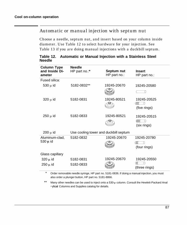
87
Cool on-column operation
Automatic or manual injection with septum nut
Choose a needle, septum nut, and insert based on your column insidediameter. Use Table 12 to select hardware for your injection. SeeTable 13 if you are doing manual injections with a duckbill septum.
Table 12. Automatic or Manual Injection with a Stainless SteelNeedle
Column Typeand Inside Di-ameter
NeedleHP part no.:* Septum nut
HP part no.:InsertHP part no.:
Fused silica:
530 m id 5182-0832** 19245-20670 19245-20580
320 m id 5182-0831 19245-80521 19245-20525
(five rings)
250 m id 5182-0833 19245-80521 19245-20515
(six rings)
200 m id Use cooling tower and duckbill septum
Aluminum-clad,530 m id
5182-0832 19245-20670 19245-20780
(four rings)
Glass capillary
320 m id
250 m id
5182-0831
5182-0833
19245-20670 19245-20550
(three rings)
* Order removable needle syringe, HP part no. 5181-0836. If doing a manual injection, you mustalso order a plunger button, HP part no. 5181-8866.
** Many other needles can be used to inject onto a 530-m column. Consult the Hewlett-Packard Analí\WLFDO Columns and Supplies catalog for details.

88
Cool on-column operation
Manual injection with a cooling tower and duckbillseptum
If you are doing this type of manual injection, use either fused silica ormetal removable stainless steel needles. Use Table 13 to choose thecorrect insert and syringe.
Table 13. Manual Injection Hardware—Cooling Tower & DuckbillSeptum
Column Type and Inside Diameter Insert (HP part no.)
Fused silica
530 m 19245-20580 (no rings)
320 m 19245-20525 (five rings)
250 m 19245-20515 (six rings)
200 m (fused silica needle only) 19245-20510 (one ring)
Aluminum-clad, 530 m 19245-20780 (four rings)
Glass capillary 19245-20550 (three rings)
Syringe and needle
Fused silica needle syringe (HP part no. 9301-0658)Replacement needles (HP part no. 19091-63000)
or
Metal removable needle syringe (HP part no. 9301-0562)Replacement needles (HP part no. 9301-0561)
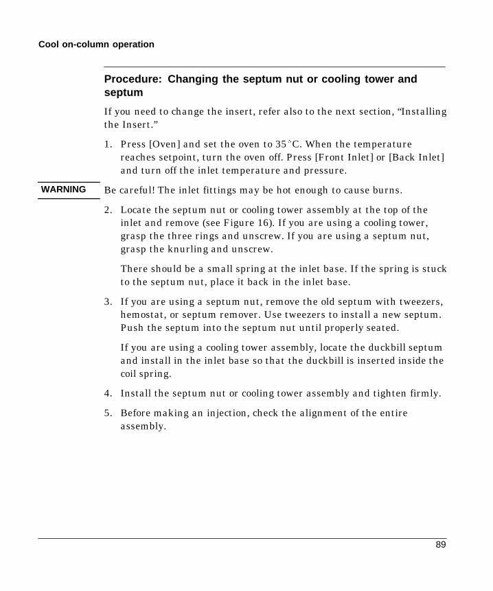
89
Cool on-column operation
Procedure: Changing the septum nut or cooling tower andseptum
If you need to change the insert, refer also to the next section, “Installingthe Insert.”
1. Press [Oven] and set the oven to 35EC. When the temperaturereaches setpoint, turn the oven off. Press [Front Inlet] or [Back Inlet]and turn off the inlet temperature and pressure.
Be careful! The inlet fittings may be hot enough to cause burns.
2. Locate the septum nut or cooling tower assembly at the top of theinlet and remove (see Figure 16). If you are using a cooling tower,grasp the three rings and unscrew. If you are using a septum nut,grasp the knurling and unscrew.
There should be a small spring at the inlet base. If the spring is stuckto the septum nut, place it back in the inlet base.
3. If you are using a septum nut, remove the old septum with tweezers,hemostat, or septum remover. Use tweezers to install a new septum.Push the septum into the septum nut until properly seated.
If you are using a cooling tower assembly, locate the duckbill septumand install in the inlet base so that the duckbill is inserted inside thecoil spring.
4. Install the septum nut or cooling tower assembly and tighten firmly.
5. Before making an injection, check the alignment of the entireassembly.
WARNING
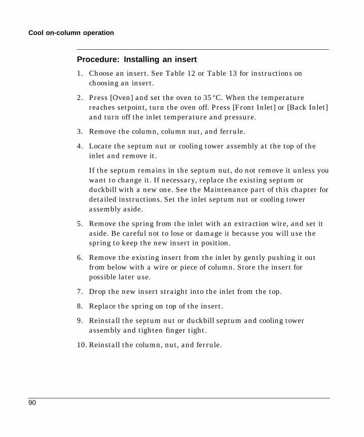
90
Cool on-column operation
Procedure: Installing an insert
1. Choose an insert. See Table 12 or Table 13 for instructions onchoosing an insert.
2. Press [Oven] and set the oven to 35EC. When the temperaturereaches setpoint, turn the oven off. Press [Front Inlet] or [Back Inlet]and turn off the inlet temperature and pressure.
3. Remove the column, column nut, and ferrule.
4. Locate the septum nut or cooling tower assembly at the top of theinlet and remove it.
If the septum remains in the septum nut, do not remove it unless youwant to change it. If necessary, replace the existing septum orduckbill with a new one. See the Maintenance part of this chapter fordetailed instructions. Set the inlet septum nut or cooling towerassembly aside.
5. Remove the spring from the inlet with an extraction wire, and set itaside. Be careful not to lose or damage it because you will use thespring to keep the new insert in position.
6. Remove the existing insert from the inlet by gently pushing it outfrom below with a wire or piece of column. Store the insert forpossible later use.
7. Drop the new insert straight into the inlet from the top.
8. Replace the spring on top of the insert.
9. Reinstall the septum nut or duckbill septum and cooling towerassembly and tighten finger tight.
10. Reinstall the column, nut, and ferrule.

91
Cool on-column operation
Procedure: Check the needle-to-column size
This applies to 250 ³ and 320 ³ columns only.
After selecting an insert and before installing a column, you need tocheck the needle-to-column size to make certain your needle fits in thecolumn. You could bend the needle if you try to inject it into a smallercolumn. Use the insert that is the same size as your syringe needle toverify that the column you plan to use is the correct size.
1. Identify the correct insert.
2. Insert the column into one end of the insert as shown below.
Syringe
Insert
Column
3. Insert the syringe needle through the other end of the insert and intothe column. If the needle cannot pass easily into the column, reversethe insert to try the needle and column in the other end.
If the needle still cannot pass into the column, you may have a columnwith an incorrect id. Check the column to make sure it is labeledcorrectly, and try a new column.
Caution
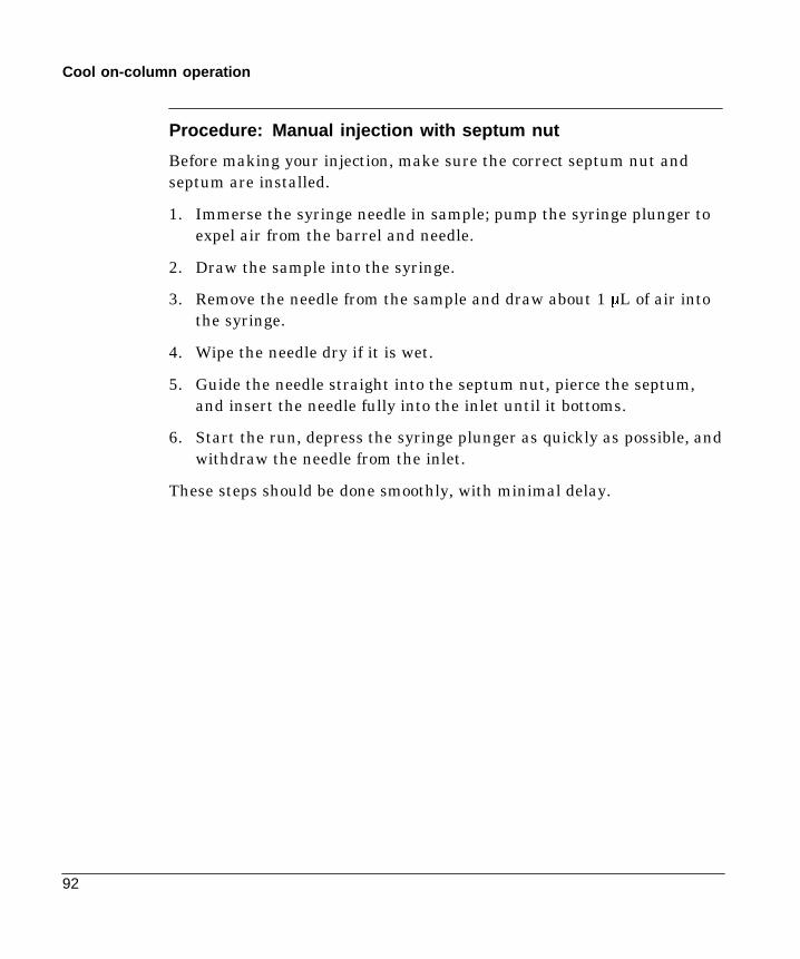
92
Cool on-column operation
Procedure: Manual injection with septum nut
Before making your injection, make sure the correct septum nut andseptum are installed.
1. Immerse the syringe needle in sample; pump the syringe plunger toexpel air from the barrel and needle.
2. Draw the sample into the syringe.
3. Remove the needle from the sample and draw about 1 ³L of air intothe syringe.
4. Wipe the needle dry if it is wet.
5. Guide the needle straight into the septum nut, pierce the septum,and insert the needle fully into the inlet until it bottoms.
6. Start the run, depress the syringe plunger as quickly as possible, andwithdraw the needle from the inlet.
These steps should be done smoothly, with minimal delay.
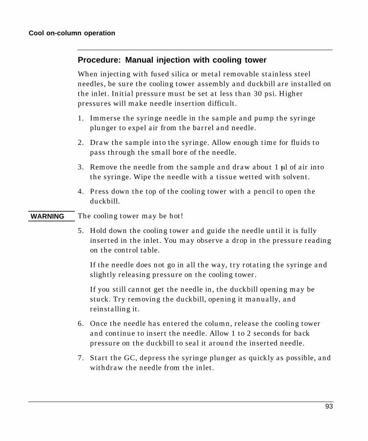
93
Cool on-column operation
Procedure: Manual injection with cooling tower
When injecting with fused silica or metal removable stainless steelneedles, be sure the cooling tower assembly and duckbill are installed onthe inlet. Initial pressure must be set at less than 30 psi. Higherpressures will make needle insertion difficult.
1. Immerse the syringe needle in the sample and pump the syringeplunger to expel air from the barrel and needle.
2. Draw the sample into the syringe. Allow enough time for fluids topass through the small bore of the needle.
3. Remove the needle from the sample and draw about 1 ³l of air intothe syringe. Wipe the needle with a tissue wetted with solvent.
4. Press down the top of the cooling tower with a pencil to open theduckbill.
The cooling tower may be hot!
5. Hold down the cooling tower and guide the needle until it is fullyinserted in the inlet. You may observe a drop in the pressure readingon the control table.
If the needle does not go in all the way, try rotating the syringe andslightly releasing pressure on the cooling tower.
If you still cannot get the needle in, the duckbill opening may bestuck. Try removing the duckbill, opening it manually, andreinstalling it.
6. Once the needle has entered the column, release the cooling towerand continue to insert the needle. Allow 1 to 2 seconds for backpressure on the duckbill to seal it around the inserted needle.
7. Start the GC, depress the syringe plunger as quickly as possible, andwithdraw the needle from the inlet.
WARNING

94
Cool on-column operation
Retention gaps
Because the sample is injected directly onto the column, it is stronglysuggested that a retention gap—or guard column—be used to protectyour column. A retention gap is a deactivated column that is connectedbetween the inlet and the analytical column. If you choose to use one, itis suggested that at least 1 m of retention gap be installed per 1 mL ofsample injected. Information on ordering retention gaps can be found inthe Hewlett-Packard Analytical Columns and Supplies Catalog.
If you are using a retention gap and are operating with column defined,the length of the retention gap could affect the calculations for flow andvelocity through your column. If your retention gap is the same insidediameter as your column, it is a good idea to add the retention gap andcolumn length before entering the number on the Configure Columncontrol table. If the retention gap inside diameter is larger than yourcolumn, this step may not be necessary.
Inlet temperature
CryoBlast (optional)
CryoBlast shortens the cycle time between runs. If you have a CO2 or N2cryogenic valve and the cryoblast feature, you can cool the inlet to 37ECin either the track oven or temperature program modes.
Track oven mode
In the Track oven mode, the inlet temperature stays 3EC higher than theoven temperature throughout the oven program. You cannot enter atemperature setpoint—it is set automatically. If you have CryoBlast, theinlet will track oven temperatures to 40EC; without CryoBlast, thelower limit is set by room temperature.
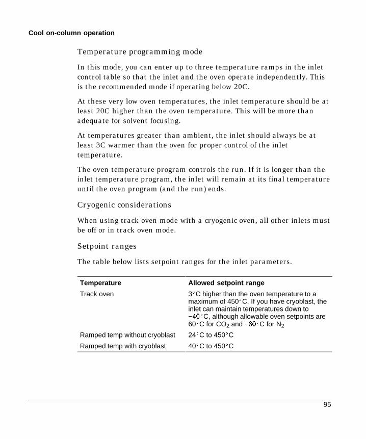
95
Cool on-column operation
Temperature programming mode
In this mode, you can enter up to three temperature ramps in the inletcontrol table so that the inlet and the oven operate independently. Thisis the recommended mode if operating below 20C.
At these very low oven temperatures, the inlet temperature should be atleast 20C higher than the oven temperature. This will be more thanadequate for solvent focusing.
At temperatures greater than ambient, the inlet should always be atleast 3C warmer than the oven for proper control of the inlettemperature.
The oven temperature program controls the run. If it is longer than theinlet temperature program, the inlet will remain at its final temperatureuntil the oven program (and the run) ends.
Cryogenic considerations
When using track oven mode with a cryogenic oven, all other inlets mustbe off or in track oven mode.
Setpoint ranges
The table below lists setpoint ranges for the inlet parameters.
Temperature Allowed setpoint range
Track oven 3EC higher than the oven temperature to amaximum of 450EC. If you have cryoblast, theinlet can maintain temperatures down to�EC, although allowable oven setpoints are60EC for CO2 and �EC for N2
Ramped temp without cryoblast 24EC to 450EC
Ramped temp with cryoblast 40EC to 450EC

96
Cool on-column operation
Procedure: Programming the temperature
1. Press [Front Inlet] or [Back Inlet].
2. Press [Mode/Type] and select Ramped temp.
Ramped temp modePress [Mode/Type]
FRONT INLET (COC)Mode: Ramped temp <Temp 100 100Init time 1.00Rate 1 4.00Final temp 1 200Final time 1 35.00Rate 2 (off) 0.00Pressure 10.0 10.0
FRONT INLET MODETrack oven
*Ramped temp <
3. Enter a Temperature. This is the starting temperature.
4. Enter an Init time. This is the length of time the inlet will stay at thestarting temperature after a run has begun.
5. Enter a Rate. This is the rate at which the inlet will be heated orcooled. A Rate of 0 halts further programming.
6. Enter the Final temp. This is the inlet temperature at the end of thefirst ramp.
7. Enter the Final time. This is the number of minutes the inlet holdsthe Final temp.
8. To enter a second (or third) ramp, scroll to the appropriate Rate lineand repeat steps 5 through 7.

97
Cool on-column operation
Procedure: Operating the cool on-column inlet
Verify that a column and suitable insert and septum nut or cooling towerare installed. Make certain you are using a needle that will fit thecolumn.
1. See Appendix A to verify that the column, carrier gas, and flow orpressure program (if used) are configured correctly.
Pressure can be set from either the column or inlet table. In constantor ramped flow mode, the pressure will be determined from the flowrequirements. It is best to set flow only.
FRONT INLET (COC)Mode: Track ovenTemp 24 OffPressure 10.0 10.0
Track oven mode Ramped temp mode
FRONT INLET (COC)Mode: Ramped tempTemp 100 100Init time 1.00Rate 1 4.00Final temp 1 200Final time 1 35.00Rate 2 (off) 0.00Pressure 10.0 10.0
2. Press [Front Inlet] or [Back Inlet]
a. Choose a temperature mode: Track oven or Ramped temp.
b. For Ramped temp mode, enter your temperature ramps (page96). There is no setpoint for Track oven mode.
3. Inject a sample.

98
Cool on-column maintenance
Part 2. Maintaining a Cool On-Column Inlet
Maintaining the cool on-column inlet includes changing septa, cleaninginlet components, and checking and correcting leaks in the system.
The cool on-column inlet’s hardware will vary depending on whether youwill be making manual or automated injections, the type of needle youuse, and the size of column you use.
Figure 17. The Cool On-Column Inlet for Automatic InjectionSystems
Spring
Insert (varies accordingto column used)
Septum
Septum nut(530-m columns)Septum nut
(250- and 320-m columns)
Septum

99
Cool on-column maintenance
Figure 18. The Cool On-Column Inlet for Manual Injection Systems
Spring
Insert (varies accordingto column used)
Cooling tower assemblyHP part no.19320-80625
Duckbill septumHP part no. 19245-40050

100
Cool on-column maintenance
Cool on-column inlet hardware problems
The inlet cools very slowly
- The inlet fan is not running or is blowing away from the inlet. Checkthe fan to make sure it is operating. If it is not, contact yourHewlett-Packard service representative.
The inlet is unable to reach a temperature setpoint
- Check the temperature equilibration time. If the equilibration time istoo short, the inlet may oscillate. Increase the equilibration time.
- Check that the cryogenic cooling is turned off. If you do not turn offcryogenic cooling when it is not in use, both the inlet and the ovenmay be unable to reach a temperature setpoint, particularlytemperatures near room temperature. If you turn the cryogeniccooling off and the inlet still fails to reach the setpoint temperature,contact your Hewlett-Packard service representative.
The syringe needle bends during injections
- The needle may have been defective before the injection was made.Check each syringe before injection to make sure the needle isstraight.
- Check that the needle support assembly is installed correctly
- Check that the correct insert is installed and that it is installedcorrectly
- Check the alignment of the inlet septum and the septum nut.
- The inlet septum hole may have closed. Replace the septum.
If you are using the GC Automatic Liquid Sampler (GC ALS):
See the GC ALS manual for additional information.
- The sampler vials may be over-crimped.
- Check the needle guide for signs of wear or damage. Replace theneedle guide if necessary.
- Check the alignment of the inlet and the automatic sampler.
101
Cool on-column maintenance
Procedure: Replacing the fused silica syringe needle
1. Hold the syringe vertically and insert the fused silica needle so it isvisible inside the syringe barrel. If the fused silica needle cannot beinserted into the syringe barrel, the Teflon ferrule (HP part no.0100-1389) may be blocked. You may need to replace the ferrule.Push the plunger down until it bottoms. The needle will now be flushwith the end of the plunger.
2. When the needle is inserted, tighten the retaining nut to firm fingertightness. Pull the needle gently to be sure the Teflon ferrule hasformed a tight seal with the needle. Tighten the retaining nutfurther, if necessary.
3. Loosen the retaining nut just enough so the needle is again free.Depress the syringe plunger slowly until it pushes the needle to theend of the barrel, then tighten the retaining nut to firm fingertightness.
4. Use a solvent to rinse the syringe and check for leaks or blocks.
5. Leaks (inability to eliminate air bubbles) may be fixed by furthertightening the retaining nut. Blocks (or serious leaks) requirerepeating this procedure.
The Teflon ferrule may lose its seal in time. If so, first retighten theretaining nut and, if the seal still leaks, install a new Teflon ferrule andneedle.
When not in use, loosen the retaining nut to avoid premature leaks.

102
Cool on-column maintenance
Procedure: Installing a fused silica needle
Fused silicaneedle
FerrulesleeveTeflonferrule
If you are cutting replacement needles directly from fused silica columnmaterial:
1. Column material for making needles must have an outside diametersmaller than both the inside diameter of the on-column inlet (0.23mm) and the inside diameter of the installed column.
2. Column material must be washed free of active stationary phase.
3. Score the column material about 1/4 inch from its end. Break off theend and discard. Then measure, score, and break off a 115 + 5 mmlength to use as the syringe needle.
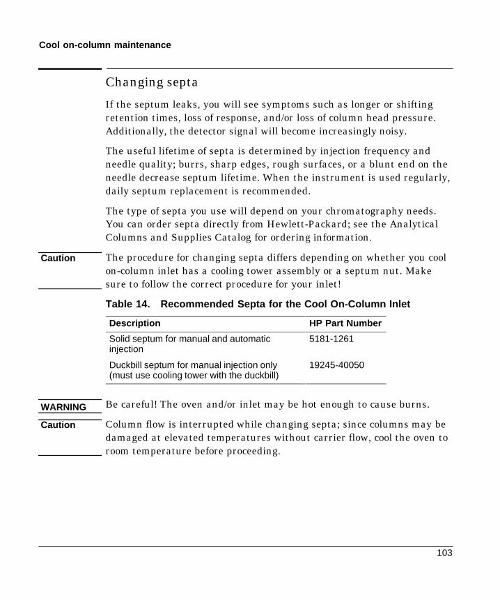
103
Cool on-column maintenance
Changing septa
If the septum leaks, you will see symptoms such as longer or shiftingretention times, loss of response, and/or loss of column head pressure.Additionally, the detector signal will become increasingly noisy.
The useful lifetime of septa is determined by injection frequency andneedle quality; burrs, sharp edges, rough surfaces, or a blunt end on theneedle decrease septum lifetime. When the instrument is used regularly,daily septum replacement is recommended.
The type of septa you use will depend on your chromatography needs.You can order septa directly from Hewlett-Packard; see the AnalyticalColumns and Supplies Catalog for ordering information.
The procedure for changing septa differs depending on whether you coolon-column inlet has a cooling tower assembly or a septum nut. Makesure to follow the correct procedure for your inlet!
Table 14. Recommended Septa for the Cool On-Column Inlet
Description HP Part Number
Solid septum for manual and automaticinjection
5181-1261
Duckbill septum for manual injection only(must use cooling tower with the duckbill)
19245-40050
Be careful! The oven and/or inlet may be hot enough to cause burns.
Column flow is interrupted while changing septa; since columns may bedamaged at elevated temperatures without carrier flow, cool the oven toroom temperature before proceeding.
Caution
WARNING
Caution

104
Cool on-column maintenance
Procedure: Changing septa
Materials needed:
- New septum—see Table 14 on page 103 for part numbers- Forceps (or tweezers)- A thin wire (0.2-in. diameter) for removing septum from inlet
Depending on your analysis and injection technique, the inlet will haveone of the following septum nuts or a cooling tower assembly.
1. Complete the following preliminary steps:- If you have entered parameters that you do not want to lose, store
them as a method.- Cool the oven to room temperature and then turn the oven off.- Cool the inlet to room temperature and then turn the inlet off.
Septum nut for injectionsonto 530-m columns
Septum nut for injections onto250- and 320-m columns
Cooling tower assembly(for manual injectionsonly)
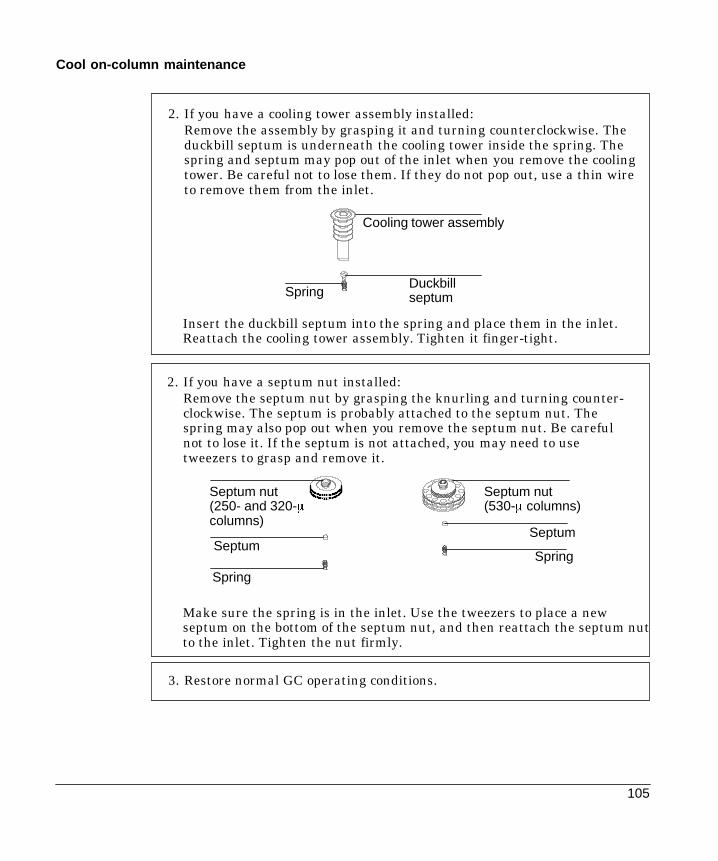
105
Cool on-column maintenance
2. If you have a cooling tower assembly installed:Remove the assembly by grasping it and turning counterclockwise. Theduckbill septum is underneath the cooling tower inside the spring. Thespring and septum may pop out of the inlet when you remove the coolingtower. Be careful not to lose them. If they do not pop out, use a thin wireto remove them from the inlet.
Spring
Cooling tower assembly
Duckbillseptum
2. If you have a septum nut installed:Remove the septum nut by grasping the knurling and turning counter-clockwise. The septum is probably attached to the septum nut. Thespring may also pop out when you remove the septum nut. Be carefulnot to lose it. If the septum is not attached, you may need to usetweezers to grasp and remove it.
SpringSeptum
Septum nut(530-m columns)
Septum nut(250- and 320-mcolumns)
Septum
Spring
Insert the duckbill septum into the spring and place them in the inlet.Reattach the cooling tower assembly. Tighten it finger-tight.
Make sure the spring is in the inlet. Use the tweezers to place a newseptum on the bottom of the septum nut, and then reattach the septum nutto the inlet. Tighten the nut firmly.
3. Restore normal GC operating conditions.

106
Cool on-column maintenance
Procedure: Cleaning the inlet
Most laboratories have airborne lint and dust that accumulate on thecooling tower or septum nut and can enter the inlet or column on thesyringe needle. Particulate matter in the inlet interferes with easypassage of the syringe needle. If dirt enters the column, it can alter thechromatography.
You can clean the needle guides, springs and inserts according to thefollowing procedure.
Be careful! The oven and/or inlet may be hot enough to cause burns.
Materials needed:
- 9/16-in. wrench- Narrow wire (0.02-in. diameter) or piece of capillary column (250-³
diameter) for removing spring and insert- Small ultrasonic cleaning bath with aqueous detergent- Distilled water- Methanol- Compressed, filtered, dry air or nitrogen
WARNING

107
Cool on-column maintenance
1. Complete the following preliminary steps:- If you have entered parameters that you do not want to lose, store
them as a method.- Allow the oven and inlet to cool.- Turn off all flows to the inlet at the initial gas supply.- Turn off the GC and unplug it.- Remove the column. See the “Columns and Traps” chapter in the
General Information volume.
2. If you have a cooling tower assembly installed:Remove the assembly by grasping it and turning counterclockwise.The septum is underneath the cooling tower inside the spring. Thespring and septum may pop out of the inlet when you remove thecooling tower. Be careful not to lose them. If they do not pop out, usea thin wire to remove them from the inlet.
Spring
Cooling tower assembly
Duckbillseptum
2. If you have a septum nut installed:Remove the septum nut by grasping the knurling and turningcounter-clockwise. The septum is probably attached to the septum nut. Thespring may also pop out when you remove the septum nut. Be carefulnot to lose it.
SpringSeptum
Septum nut(530-mcolumns)
Septum nut(250- and 320-mcolumns)
Septum
Spring

108
Cool on-column maintenance
3. Insert the narrow wire (or a piece of capillary column) into the inletthrough the oven, and push the insert and spring (if they did notcome out previously) out through the top of the inlet.
Spring
Insert (variesaccording to columnuse)
Insert wire into inlet from oven
7. Attach the septum nut or the cooling tower and tighten finger-tight.Reinstall the column, and then restore normal operation conditions.
4. Cleaning procedure:a. Fill the ultrasonic cleaning bath with aqueous detergent, and place
the spring and the insert into it. Sonicate for one minute.b. Drain the aqueous detergent, and fill the bath with distilled water.
Sonicate for one minute.c. Remove the parts from the bath, and rinse them thoroughly with
water and methanol.d. Dry the parts with a burst of compressed air or nitrogen.
5. Reinstall the insert. If you are using a septum nut, insert the springand insert, with the spring on top.
6. Attach a new septum to the bottom of the septum nut. If you are usingthe cooling tower assembly, insert a new duckbill septum into thespring, and place them in the inlet.
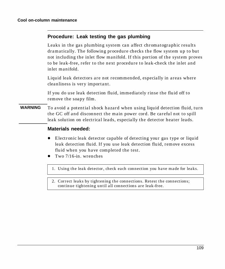
109
Cool on-column maintenance
Procedure: Leak testing the gas plumbing
Leaks in the gas plumbing system can affect chromatographic resultsdramatically. The following procedure checks the flow system up to butnot including the inlet flow manifold. If this portion of the system provesto be leak-free, refer to the next procedure to leak-check the inlet andinlet manifold.
Liquid leak detectors are not recommended, especially in areas wherecleanliness is very important.
If you do use leak detection fluid, immediately rinse the fluid off toremove the soapy film.
To avoid a potential shock hazard when using liquid detection fluid, turnthe GC off and disconnect the main power cord. Be careful not to spillleak solution on electrical leads, especially the detector heater leads.
Materials needed:
- Electronic leak detector capable of detecting your gas type or liquidleak detection fluid. If you use leak detection fluid, remove excessfluid when you have completed the test.
- Two 7/16-in. wrenches
1. Using the leak detector, check each connection you have made for leaks.
2. Correct leaks by tightening the connections. Retest the connections;continue tightening until all connections are leak-free.
WARNING
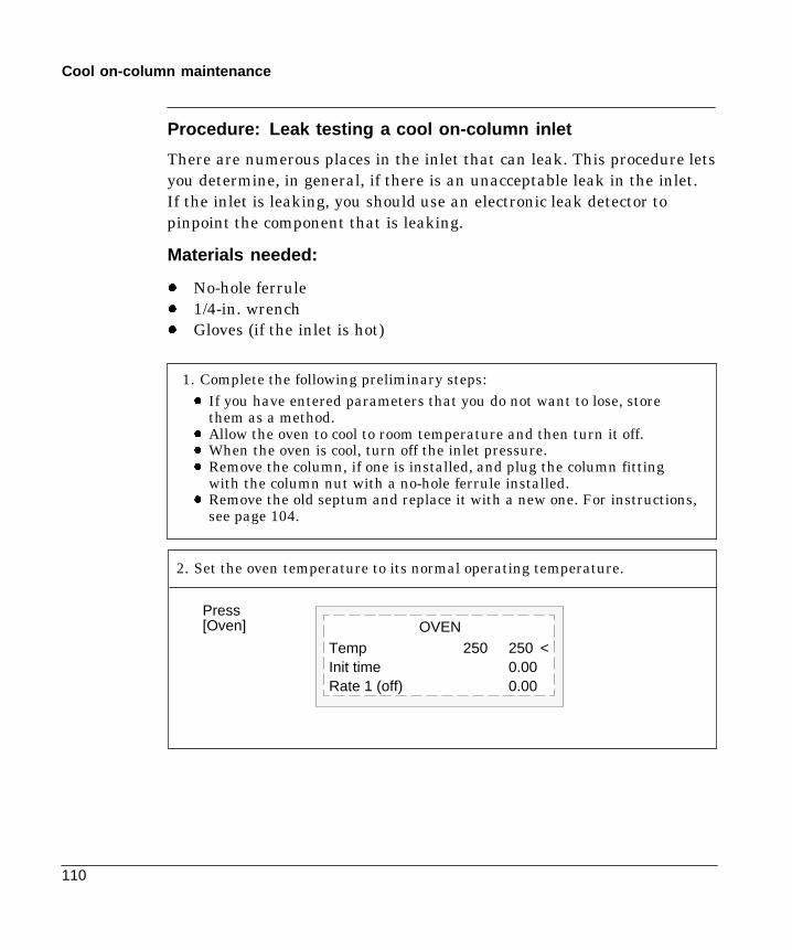
110
Cool on-column maintenance
Procedure: Leak testing a cool on-column inlet
There are numerous places in the inlet that can leak. This procedure letsyou determine, in general, if there is an unacceptable leak in the inlet.If the inlet is leaking, you should use an electronic leak detector topinpoint the component that is leaking.
Materials needed:
- No-hole ferrule- 1/4-in. wrench- Gloves (if the inlet is hot)
1. Complete the following preliminary steps:- If you have entered parameters that you do not want to lose, store
them as a method.- Allow the oven to cool to room temperature and then turn it off.- When the oven is cool, turn off the inlet pressure.- Remove the column, if one is installed, and plug the column fitting
with the column nut with a no-hole ferrule installed.- Remove the old septum and replace it with a new one. For instructions,
see page 104.
2. Set the oven temperature to its normal operating temperature.
Temp 250 250 <Init time 0.00Rate 1 (off) 0.00
OVENPress[Oven]

111
Cool on-column maintenance
3. Set inlet to normal operating temperature. Enter a pressure between 20and 25 psi, or enter your normal operating pressure, if it is higher. Makesure that the pressure at the initial gas supply is at least 10 psi higherthan the inlet pressure.
Mode: Track ovenTemp 150 150 <Pressure 24.0 24.0Total flow 0.0
FRONT INLET (coc)Press [Front Inlet] or[Back Inlet]
OR
Mode: Ramped tempTemp 150 150 <Init time 0.00Rate 1 (Off) 0.00Pressure 24.0 On
FRONT INLET (coc)
4. Wait a few minutes for the GC to equilibrate after the system hasreached the pressure. (The rest of the examples of the Front Inlet controltable will show the table that appears if the inlet is in track mode.)
The GC may exceedthe pressure setpointslightly whileequilibrating.
Mode: Track ovenTemp 150 150Pressure 24.2 24.0<
FRONT INLET (coc)Press [Front Inlet]or [Back Inlet]

112
Cool on-column maintenance
6. Continue to monitor pressure for 10 to 15 minutes. You can use the GC’sStopwatch function. A pressure drop of 0.03 psi/min or less is acceptable.
5. Turn the pressure off. Because the column is capped, the pressureshould remain fairly constant.
Because the pneumatics have been turned off, the alarm does not soundeven though there is no flow through the column.
Press [FrontInlet] or [BackInlet]
9:56:08 12 Dec 94Last runtime 0.00Next runtime 999.99t = 0:04.9 1/t = 12.24
Press [Time]
Mode: Track ovenTemp 150 150Pressure 24.2 Off<
FRONT INLET (coc)
If the pressure drop is 0.03 psi/min or less, you can consider the inletsystem leak-free.
If the pressure drops faster than the acceptable rate, go to the next section,“Correcting Leaks.”

113
Cool on-column maintenance
Procedure: Correcting leaks
Materials needed:
- Electronic leak detector- 1/4-in. wrench
1. Use the electronic leak detector to check all areas of the inlet that arepotential sources of a leak. Potential leak areas are:
- The plugged column connection- The septum nut, if present- The cooling tower assembly, if present
2. Correct leaks, using the wrench if necessary, to tighten connections. Youmay need to repeat the leak test again to check for leaks.
If the pressure drop is now 0.03 psi/min or less, you can consider the inletsystem leak-free.
If the pressure drops faster than the acceptable rate, continue to search forleaks and repeat the pressure test. If all fittings appear to be leak free, butthe inlet system is still losing too much pressure, you may need to replacethe inlet manifold. Contact your Hewlett-Packard service representative.

5
The Programmable Tempera-ture Vaporization Inlet
Part 1. Introducing the HP PTVOperating modes and system requirements, 116System components, 117Heating and cooling the inlet, 119
Part 2. Using the Split ModesProcedure: Split mode, column defined, 126Procedure: Split mode, column not defined, 127Procedure: Pulsed split mode, column defined, 130Procedure: Pulsed split mode, column not defined, 131
Part 3. Using the Splitless ModesProcedure: Splitless mode, column defined, 138Procedure: Splitless mode, column not defined, 139Procedure: Pulsed splitless mode, column defined, 141Procedure: Pulsed splitless mode, column not defined, 142
Part 4. Using the Solvent Vent ModeSequence of operations and timelines, 146When is Start Run?, 148Procedure: Solvent vent mode, column defined, 151Procedure: Solvent vent mode, column not defined, 152Large volume injection, 153
Part 5. Maintaining a PTVInlet adapters, 161Procedure: Installing columns, 162The septumless head, 164The septum head, 168Glass inlet liners, 171
116
Chapter 5.The Programmable TemperatureVaporization Inlet
Part 1. Introducing the HP PTV
Operating modes
The Hewlett-Packard Programmed Temperature Vaporization (PTV)Inlet System has five operating modes:
- The split mode is generally used for major component analyses.
- The pulsed split mode is like the split mode, but with a pressurepulse applied to the inlet during sample introduction to speed thetransfer of material to the column.
- The splitless mode is used for trace analyses.
- The pulsed splitless mode allows for a pressure pulse during sampleintroduction.
- The solvent vent mode is used for large volume injection. Eithersingle or multiple injections can be made for each run.
System requirements
The PTV inlet can be used with both manual and automatic injection.
If an HP automatic sampler is used, it must be a model G1513Aautosampler (firmware G1513A.09.14 or later) with a G1512A controller(firmware G1512A.01.08 or later)
For automatic multiple injections (large volume injections), an HP GC orMSD ChemStation is required. This function is not available under HP6890 control alone. See part 4 of this chapter.

117
PTV introduction
System components
1. The pneumatics module, located at the top rear of the GC.
2. The inlet body, always mounted in the front inlet position.
3. The trap, which is in the split line and placed to the left of thepneumatics carrier at the top rear of the chromatograph.
4. The coolant control valve. For liquid nitrogen, this valve is on the leftoutside wall of the oven. For liquid carbon dioxide, it is in thepneumatics carrier. These valves are not interchangeable—if youchange coolants, you must also change all of the coolant plumbingincluding the valve and inlet jacket.
5. The thermocouple conversion board. It converts thermocouplereadings from the inlet for use by the GC and is near the trap.
Figure 19. PTV system components
With septum headWith septumlesshead
Alternate purge flow paths
PV1
PV2 SPR
Sol PS
FS
Trap
InletCarriersupply
Splitvent
Septum purge vent
PV Proportional valveSPR Septum purge regula-torSol Solenoid valvePS Pressure sensorFS Flow sensorCCV Cryogenic coolantvalve
Pneumatics module Coolantsupply
CCV

118
PTV introduction
Sampling heads
Two heads are available for the PTV inlet.
- The septum head uses either a regular septum or a Merlinmicroseal to seal the syringe passage. A stream of gas sweeps theinner side of the septum and exits through the septum purge vent onthe pneumatics module. It may be used with either automatic ormanual injection.
At inlet temperatures below 40C, the Merlin microseal may not sealeffectively—use a regular septum instead.
- The septumless head uses a check valve instead of a septum to sealthe syringe entrance passage. It may be used with either automaticor manual injection.
Figure 20. Sampling heads
Carrier gas and septumpurgelines to pneumatics mod-ule
Carrier gas line
Septum head Septumless head
Note:Two gas lines (carriersupply and septumpurge), meeting at thepneumatics module.Uses either standard 11mm septa or (with a dif-ferent cap) a Merlin mi-croseal.
Note:One gas line (carriersupply).No septum, so no sep-tum purge line. Septumpurge stream exitsthrough bypass line.
The flow diagrams in the rest of this book show the septum head in placewith a separate drawing for the septumless head plumbing.
Caution

119
PTV introduction
Heating the inlet
The control parameters for PTV temperature programming are the sameas for the column oven, but are reached by pressing [Front Inlet].Temperature can be programmed with an initial temperature and up to3 rates and plateaus. Rates between 0.1 and 720C/min can be selected.See chapter 4 of the General Information volume for details.
If the initial inlet temperature and the oven initial temperature are tooclose, the inlet may be unable to maintain its setpoint. We recommend adifference of at least 6C, either higher or lower.
Additional temperature ramps
For most purposes, the PTV is designed to hold the sample in the inletliner until the entire sample—there could be several injections—hasbeen injected. Then the PTV is heated rapidly to transfer the sample tothe column. This can be accomplished with an initial hold, a single ramp,and a hold at the end to complete sample transfer.
Two additional ramps are available and have several possible uses:
- The inlet can be heated to a high temperature to thermally clean theliner for the next run.
- The inlet can be programmed downward—just set the Final tempbelow the previous temperature—to reduce thermal stress on theinlet.
- Downward programming can be used to prepare the inlet for the nextrun. This can reduce cycle time for greater sample throughput.
Caution
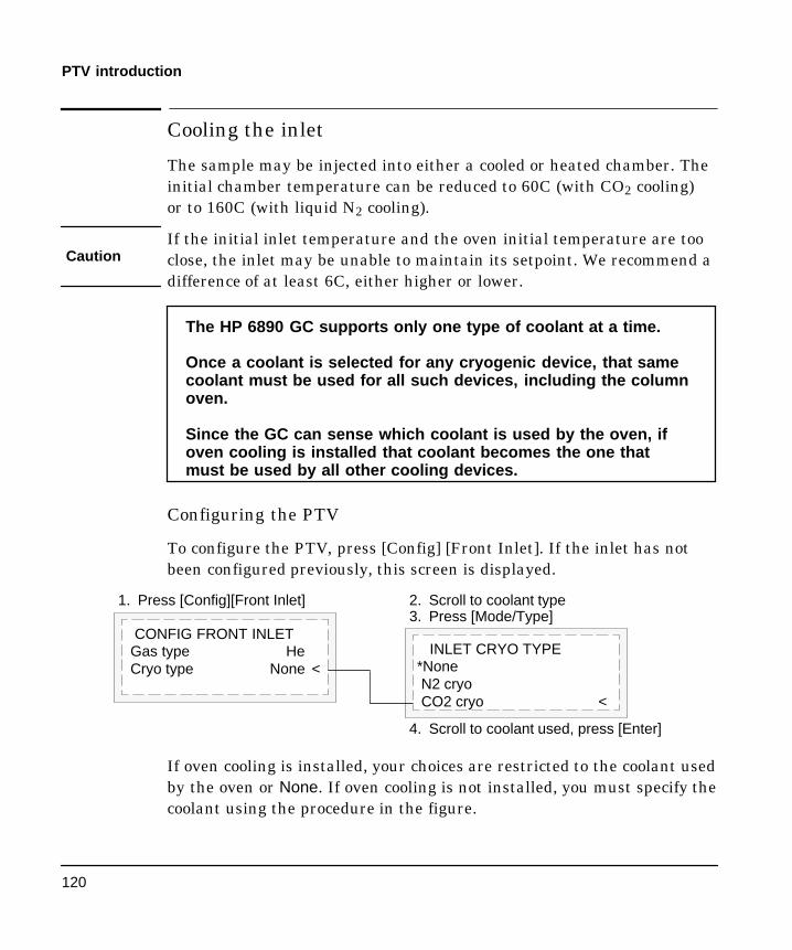
120
PTV introduction
Cooling the inlet
The sample may be injected into either a cooled or heated chamber. Theinitial chamber temperature can be reduced to 60C (with CO2 cooling)or to 160C (with liquid N2 cooling).
If the initial inlet temperature and the oven initial temperature are tooclose, the inlet may be unable to maintain its setpoint. We recommend adifference of at least 6C, either higher or lower.
The HP 6890 GC supports only one type of coolant at a time.
Once a coolant is selected for any cryogenic device, that samecoolant must be used for all such devices, including the columnoven.
Since the GC can sense which coolant is used by the oven, ifoven cooling is installed that coolant becomes the one thatmust be used by all other cooling devices.
Configuring the PTV
To configure the PTV, press [Config] [Front Inlet]. If the inlet has notbeen configured previously, this screen is displayed.
CONFIG FRONT INLETGas type HeCryo type None <
INLET CRYO TYPE*NoneN2 cryoCO2 cryo <
2. Scroll to coolant type3. Press [Mode/Type]
4. Scroll to coolant used, press [Enter]
1. Press [Config][Front Inlet]
If oven cooling is installed, your choices are restricted to the coolant usedby the oven or None. If oven cooling is not installed, you must specify thecoolant using the procedure in the figure.
Caution

121
PTV introduction
If the Cryo type selection is anything other than None, several otherparameters appear.
CONFIG FRONT INLETGas type HeCryo type N2Cryo OffUse cryo temp 25Cryo timeout 30Cryo fault On
Cryo [ON] enables cryogenic cooling of the inlet as soon as the columnoven reaches its initial temperature. [OFF] disables cooling.
Use cryo temp If Cryo is ON, this is the upper limit of temperatures atwhich cryo cooling is used to hold the inlet at its setpoint. If the setpointis higher than this limit, cryogenic cooling is used to bring the inlet downto its setpoint but is not used to hold it at the setpoint.
Cryo timeout Cryo timeout occurs, and the inlet temperature shutsdown, when a run does not start within a specified time (range 5 to 120minutes, default 30 minutes) after the oven equilibrates. Turning cryotimeout off disables this feature. We recommend that it be turned onbecause cryo timeout conserves coolant at the end of a sequence or ifautomation fails. A Post Sequence method could also be used.
Cryo fault Shuts down the inlet temperature if it does not reach setpointin 16 minutes of continuous cryo operation. Note that this is the time toreach the setpoint, not the time to stabilize and become ready at thesetpoint.

122
PTV introduction
Shutdown behavior
Both Cryo timeout and Cryo fault can cause cryo shutdown. If thishappens, the inlet heater is turned off and the cryo valve closes. The GCbeeps and displays this message:
SHUTDOWN (#18):Front inlet cryo
shutdown
The inlet heater is monitored to avoid overheating. If the heater remainson at full power for more than 2 minutes, the heater is shut down. TheGC beeps and displays this message:
SHUTDOWN (#22):Front inlet heating
too slowly;temperature shut off
To recover from either condition, turn the GC off, then on, or enter a newsetpoint.

123
PTV split mode operation
Part 2. Using the Split Modes
Flow pattern
The two split modes—with or without a pressure pulse—divide the gasstream entering the inlet between the column flow, the split vent flowthrough the solenoid valve, and the septum purge flow. The ratio of thesplit vent flow to the column flow is called the split ratio.
The main figure shows the flows with the septum head. Flows with theseptumless head are the same except that the septum purge flowbypasses the head (lower left).
Solenoidvalveopen
Propor-tional
valve 2
Trap
To detector
Total flowcontrol loop
Flowsensor
Propor-tional
valve 1
Flowlimiting
frit Column head pres-sure control loop
Pressuresensor
Septum purgeregulator
PS SPR
Glass liner
FS
Septumpurgevent
Splitvent
PS
FS
Septumhead
Septumlesshead
Flows with septumlesshead
124
PTV split mode operation
Temperature considerations
Cold split introduction
For cold split sample introduction, use an initial inlet temperature belowthe normal boiling point of the solvent. If the liner volume is enough tohold all the vaporized solvent, start the first inlet temperature ramp at0.1 minutes with a high heating rate (500C/min or higher). The finaltemperature should be high enough to volatilize the heaviest analytesfrom the liner and should be held for at least 5 minutes. A finaltemperature of 350C for 5 minutes has proven sufficient toquantitatively transfer C44.
For larger injection volumes or to eliminate the solvent, hold the initialtemperature long enough to vent the solvent through the Split vent andthen begin the first ramp. Use a fast rate for thermally stable analytes.Slower rates may help minimize thermal degradation in the inlet.
A single temperature ramp is enough for the injection process. Theremaining ramps may be used to clean the liner or to reduce the inlettemperature in preparation for the next injection.
Hot split introduction
For hot split introduction, set an initial temperature high enough tovolatilize the analytes. No additional thermal parameters are requiredas the inlet will maintain the setpoint throughout the run.
Because of the small liner volume (about 120 microliters), the PTV has alimited injection capacity with hot split introduction. Injection volumesexceeding 1 ³L in the hot split mode may overflow the inlet causinganalytical problems. Cold split introduction avoids this potentialproblem.

125
PTV split mode operation
Control table parameters—split mode operation
Mode: The current operating mode—split
Temp Actual and setpoint inlet initial temperatures.
Init time Hold time at the inlet initial temperature.
Rate # Temperature program rate for inlet thermal ramps 1, 2, and 3.
Final temp # Final inlet temperature for ramps 1, 2, and 3.
Final time # Hold time at Final temp 1, 2, and 3.
Pressure Actual and setpoint inlet pressure
Split ratio The ratio of split flow to column flow. Column flow is set atthe Column 1 or Column 2 control table. This line does not appear ifyour column is not defined.
Split flow Flow, in mL/min, from the split/purge vent. This line does notappear if your column is not defined.
Total flow These are the actual and setpoint values of the total flow intothe inlet, which is the sum of the split flow, column flow, and septumpurge flow. When you change the total flow, the split ratio and split flowchange while the column flow and pressure remain the same.

126
PTV split mode operation
Procedure: Using split mode with the column defined
1. See Appendix A to verify that the column, carrier gas, and flow orpressure program (if used) are configured correctly.
2. Press [Front Inlet]
a. Scroll to Mode: and press [Mode/Type]. Select Split.
b. Set the inlet temperature and any desired ramps.
c. If you want a specific split ratio, scroll to Split ratio and enter thatnumber. The split flow will be calculated and set for you.
d. If you want a specific split flow, scroll to Split flow and enter thatnumber. The split ratio will be calculated and displayed for you.
e. If desired, turn on Gas saver. Set the Saver time after theinjection time.
FRONT INLET MODESolvent vent
*Split <SplitlessPulsed splitPulsed splitless
Press [Mode/Type]
If using gas saver,set time after injectiontime.
FRONT INLET (HP PTV)Mode: SplitTemp 40 40 <Init time 0.1Rate 1 600Final temp 1 350Final time 1 5.00Rate 2 (off)Pressure 9.1 9.1Split ratio 50.0Split flow 100.0Tot flow 104 104Gas saver OnSaver flow 20.0Saver time 5.00
Only one rate isnecessary for thisexample.Additional rates are atthe user’s discretion.
3. Press [Prep Run] before manually injecting the sample if the GasSaver is on (see page 13).
Split ratio =Split flow
Column flow

127
PTV split mode operation
Procedure: Using split mode with the column not defined
1. See Appendix A to verify that the column, carrier gas, and flow orpressure program (if used) are configured correctly.
2. Press [Front Inlet].
a. Set temperature.
b. Set total flow into the inlet. Measure flows out of the split ventand septum purge vent using a flow meter.
c. Subtract the septum purge flow from Total flow to get split flow.
d. Calculate the split ratio. Adjust as needed.
FRONT INLET MODESolvent vent
*Split <SplitlessPulsed splitPulsed splitless
Press [Mode/Type]FRONT INLET (HP PTV)Mode: SplitTemp 40 40 <Init time 0.10Rate 1 600Final temp 1 350Final time 1 5.00Rate 2 (off)Pressure 10.0 10.0Tot flow 80.3 80.3
Only one rate isnecessary for thisexample.Additional rates are atthe user’s discretion.
Septum purge
Split vent
Front of instrument

128
PTV split mode operation
Pulsed modes
The pressure pulse modes (split and splitless) increase inlet pressure justbefore the beginning of a run and return it to the normal value after aspecified amount of time. The pressure pulse sweeps the sample out ofthe inlet and into the column faster, reducing the chance for sampledecomposition in the inlet. If your chromatography is degraded by thepressure pulse, a retention gap may help restore peak shape.
You must press the [Prep Run] key before doing manual injections in thepressure pulse mode.
You can do column pressure and flow programming when in the pressurepulse mode. However, the pressure pulse will take precedence over thecolumn pressure or flow ramp.
Figure 21. Pressure Pulse and Column Flow or Pressure
Actualpressure
Time (min)0 1 2 3 4 5 6 7 8
Pressure pulse
Pressure (or flow) program

129
PTV split mode operation
Control table parameters—pulsed split mode
Mode: The current operating mode—pulsed split
Temp Actual and setpoint inlet temperatures
Init time Hold time at the initial inlet temperature.
Rate # Temperature program rate for inlet thermal ramps 1, 2, and 3.
Final temp # Final inlet temperature for ramps 1, 2, and 3.
Final time # Hold time at Final temp 1, 2, and 3.
Pressure Actual and setpoint inlet pressure before and after thepressure pulse. This is the starting point of a pressure program or thefixed pressure if a program is not used.
Pulsed pres The inlet pressure you desire at the beginning of a run.The pressure rises to this setpoint after [Prep Run] is pressed andremains constant until Pulse time elapses, when it returns to Pressure.
Pulse time Inlet pressure returns to its normal setpoint at this timeafter Start Run.
Split ratio The ratio of split flow to column flow. Column flow is set atthe Column 1 or Column 2 control table. This line does not appear ifyour column is not defined.
Split flow Flow, in mL/min from the split/purge vent. This line does notappear if your column is not defined.
Total flow The total flow into the inlet, the sum of the split flow, columnflow, and septum purge flow. When you change total flow, the split ratioand split flow change while column flow and pressure remain the same.When a pressure pulse is used, total flow increases to keep the split ratioconstant.
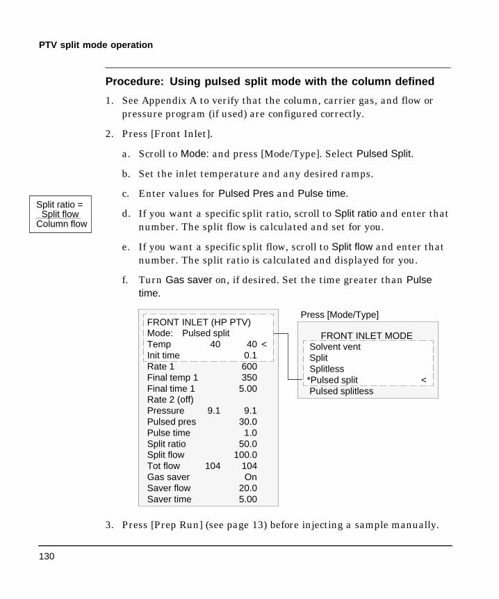
130
PTV split mode operation
Procedure: Using pulsed split mode with the column defined
1. See Appendix A to verify that the column, carrier gas, and flow orpressure program (if used) are configured correctly.
2. Press [Front Inlet].
a. Scroll to Mode: and press [Mode/Type]. Select Pulsed Split.
b. Set the inlet temperature and any desired ramps.
c. Enter values for Pulsed Pres and Pulse time.
d. If you want a specific split ratio, scroll to Split ratio and enter thatnumber. The split flow is calculated and set for you.
e. If you want a specific split flow, scroll to Split flow and enter thatnumber. The split ratio is calculated and displayed for you.
f. Turn Gas saver on, if desired. Set the time greater than Pulsetime.
FRONT INLET MODESolvent ventSplitSplitless
*Pulsed split <Pulsed splitless
FRONT INLET (HP PTV)Mode: Pulsed splitTemp 40 40 <Init time 0.1Rate 1 600Final temp 1 350Final time 1 5.00Rate 2 (off)Pressure 9.1 9.1Pulsed pres 30.0Pulse time 1.0Split ratio 50.0Split flow 100.0Tot flow 104 104Gas saver OnSaver flow 20.0Saver time 5.00
Press [Mode/Type]
3. Press [Prep Run] (see page 13) before injecting a sample manually.
Split ratio =Split flow
Column flow

131
PTV split mode operation
Procedure: Using pulsed split mode with the column notdefined
1. See Appendix A to verify that the column, carrier gas, and flow orpressure program (if used) are configured correctly.
2. Press [Front Inlet].
a. Scroll to Mode: and press [Mode/Type]. Select Pulsed Split.
b. Set the inlet temperature and any desired ramps.
c. Enter values for Pulsed Pres and Pulse time.
d. Set total flow into the inlet. Measure flows out of the split ventand septum purge vent using a flow meter.
e. Subtract the septum purge flow from Total flow.
f. Calculate the split ratio. Adjust as needed.
FRONT INLET MODESolvent ventSplitSplitless
*Pulsed split <Pulsed splitless
FRONT INLET (HP PTV)Mode: Pulsed splitTemp 40 40 <Init time 0.1Rate 1 600Final temp 1 350Final time 1 5.00Rate 2 (off)Pressure 9.1 9.1Pulsed pres 30.0Pulse time 1.0Tot flow 104 104
Press [Mode/Type]
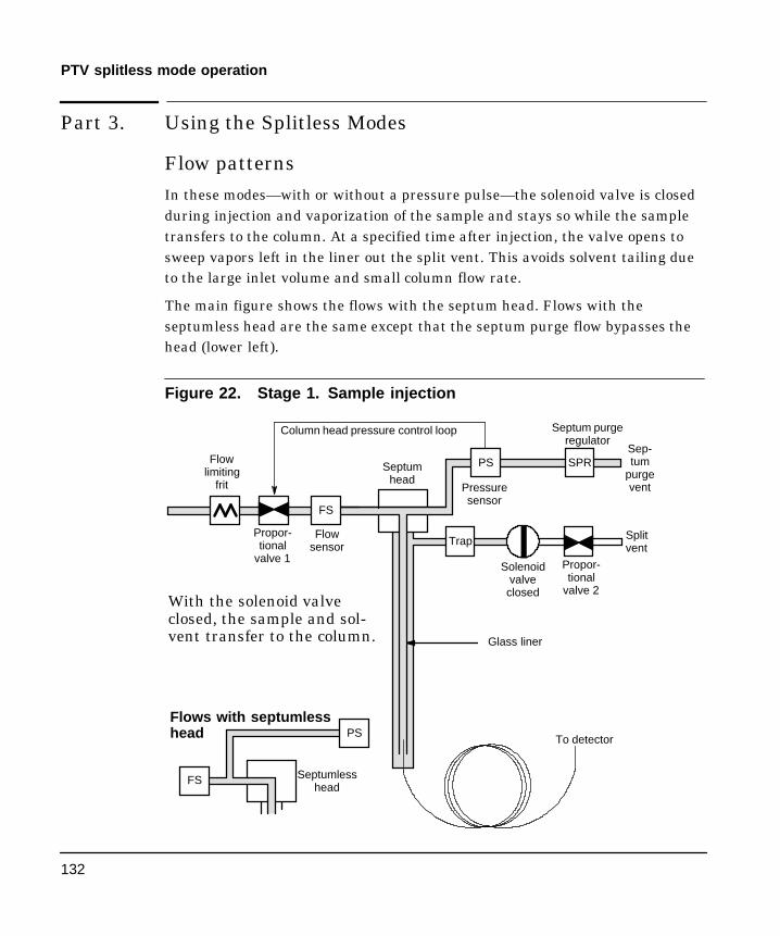
132
PTV splitless mode operation
Part 3. Using the Splitless Modes
Flow patternsIn these modes—with or without a pressure pulse—the solenoid valve is closedduring injection and vaporization of the sample and stays so while the sampletransfers to the column. At a specified time after injection, the valve opens tosweep vapors left in the liner out the split vent. This avoids solvent tailing dueto the large inlet volume and small column flow rate.
The main figure shows the flows with the septum head. Flows with theseptumless head are the same except that the septum purge flow bypasses thehead (lower left).
Figure 22. Stage 1. Sample injection
Solenoidvalveclosed
Propor-tional
valve 2
Trap
To detector
Flowsensor
Propor-tional
valve 1
Flowlimiting
frit
Column head pressure control loop
Pressuresensor
Septum purgeregulator
PS SPR
Glass liner
FS
With the solenoid valveclosed, the sample and sol-vent transfer to the column.
Sep-tum
purgevent
Splitvent
PS
FS Septumlesshead
Flows with septumlesshead
Septumhead
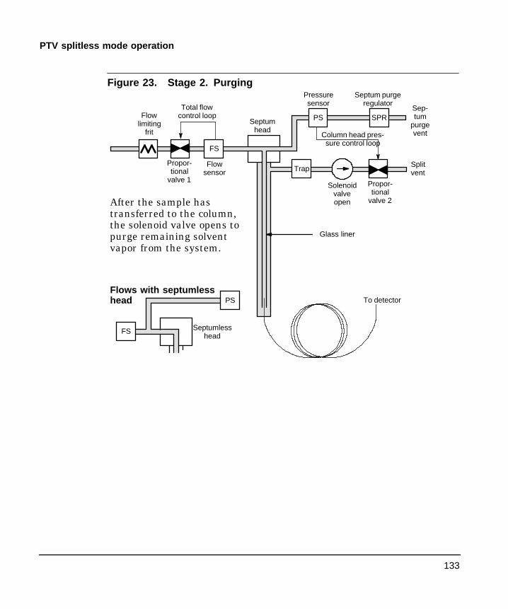
133
PTV splitless mode operation
Figure 23. Stage 2. Purging
Solenoidvalveopen
Propor-tional
valve 2
Trap
To detector
Total flowcontrol loop
Flowsensor
Propor-tional
valve 1
Flowlimiting
frit Column head pres-sure control loop
Pressuresensor
Septum purgeregulator
PS SPR
Glass liner
FS
After the sample hastransferred to the column,the solenoid valve opens topurge remaining solventvapor from the system.
Sep-tum
purgevent
Splitvent
PS
FS Septumlesshead
Flows with septumlesshead
Septumhead

134
PTV splitless mode operation
Figure 24. Flows, pressures, and temperatures
Purgeflow
Saverflow
Inlet ispressurecontrolled
PrepRun
StartRun
PurgeTime
SaverTime
StopRun
PostTime
PostPres
InletPres
PrepRun
StartRun
PurgeTime
StopRun
PostTime
SPLITLESS OPERATION
Finaltemp 1
Inittemp
Split vent flow
Inlet pressure
Inlettemperature
PrepRun
StartRun
PurgeTime
Column flow program

135
PTV splitless mode operation
Temperature considerations
Cold splitless introduction
For cold splitless introduction, use an initial inlet temperature below thenormal boiling point of the solvent. For most solvents, starting the firstinlet temperature ramp at 0.1 minutes provides good transfer andreproducibility. A program rate of 500C/min or higher is appropriate forthermally stable analytes. A final temperature of 350C, held for 5minutes, has quantitatively transferred up to C44 alkane.
A main advantage of temperature programmability is that the inlet canbe heated gently to transfer delicate analytes. If the oven temperature isinitially low enough to refocus the analytes on the column, the inletheating rate can be made slower (eg, 120C/min). This reduces thermaldegradation from the inlet and can improve peak shape andquantitation.
For most applications of cold splitless, a single temperature ramp isenough. The remaining ramps can be used to clean the liner or todecrease the inlet temperature to prepare for the next injection.
Hot splitless introduction
For hot splitless introduction, select an initial temperature high enoughto volatilize the analytes. No additional temperature parameters arerequired as the inlet will maintain the setpoint throughout the run.
Because of the small liner volume (about 120 ³L), the PTV cannotcontain vapor resulting from large liquid injection volumes. Injectionvolumes greater than 1 ³L may overflow vapor from the inlet, causinganalysis variations. Cold splitless introduction avoids this problem.

136
PTV splitless mode operation
Control table parameters—splitless operation
Mode: The current operating mode—splitless
Temp Actual and setpoint inlet temperatures
Init time Hold time at the initial inlet temperature.
Rate # Temperature program rate for inlet thermal ramps 1, 2, and 3.
Final temp # Final inlet temperature for ramps 1, 2, and 3.
Final time # Hold time at Final temp 1, 2, and 3.
Pressure Actual and setpoint inlet pressure in psi, bar, or kPa
Purge time The time, after the beginning of the run, when you want thepurge valve to open.
Purge flow The flow, in mL/min, from the purge vent, at Purge time.You will not be able to specify this value if operating with your columnnot defined.
Total flow The Total flow line displays the actual flow to the inletduring a Pre-run (Pre-run light is on and not blinking) and during a runbefore purge time. You cannot enter a setpoint at these times. At allother times, Total flow will have both setpoint and actual values.

137
PTV splitless mode operation
Starting values
A successful splitless injection consists of these steps:
1. Inject the sample and temperature program the inlet to vaporize it.
2. Use a low column flow and low oven temperature to create asolvent-saturated zone at the head of the column.
3. Use this zone to trap and reconcentrate the sample at the head of thecolumn.
4. Wait until all, or at least most, of the sample has transferred to thecolumn. Then discard the remaining vapor in the inlet—which ismostly solvent—by opening a purge valve. This eliminates the longsolvent tail that this vapor would otherwise cause.
5. Raise the oven temperature to analyze the sample.
Some experimentation is needed to refine the operating conditions.Table 16 provides starting values for the critical parameters.
Table 16. Splitless Mode Inlet Parameters
Parameter Allowed Setpoint Range Suggested StartingValue
Oven temperature No cryo, ambient+10EC to450ECCO2 cryo, �EC to 450ECN2 cryo, �EC to 450EC
��Û& below solventboiling point
Oven initial time 0 to 999.9 minutes | Inlet purge time
Inlet purge time 0 to 999.9 minutesColumn flowLiner volume*
x 5
Gas saver time 0 to 999.9 minutes After purge time
Gas saver flow 15 to 1000 mL/min 15 mL/min greaterthan maximum col-umn flow
Inlet temperature No cryo, oven temp + ��Û&
CO2 cryo, í��Û& to ���Û&
N2 cryo, í���Û& to ���Û&
��Û& below solventboiling point for 0.1min,then ramp up
* Liner volume is about 120 ³L

138
PTV splitless mode operation
Procedure: Using splitless mode with the column defined
1. See Appendix A to verify that the column, carrier gas, and flow orpressure program (if used) are configured correctly.
2. Press [Front Inlet].
a. Scroll to Mode: and press [Mode/Type]. Select Splitless.
b. Set the inlet temperature and any desired ramps.
c. Enter a purge time and a purge flow.
d. If desired, turn Gas saver on. Make certain the time is set afterthe purge flow time.
FRONT INLET (HP PTV)Mode: SplitlessTemp 40 40 <Init time 0.1Rate 1 600Final temp 1 350Final time 1 5.00Rate 2 (off)Pressure 9.1 9.1Purge time 2.0Purge flow 50.0Total flow 24.1Gas saver OnSaver flow 20.0Saver time 5.00
Press [Mode/Type]
If using gas saver,set time after purge flowtime.
FRONT INLET MODESolvent ventSplit
*Splitless <Pulsed splitPulsed splitless
3. Press [Prep Run] (see page 13) before manually injecting a sample.

139
PTV splitless mode operation
Procedure: Using splitless mode with the column not defined
1. See Appendix A to verify that the column, carrier gas, and flow orpressure program (if used) are configured correctly.
2. Press [Front Inlet].
a. Scroll to Mode: and press [Mode/Type]. Select Splitless.
b. Set the inlet temperature and any desired ramps.
c. Enter a purge time.
d. Set your total flow greater than the column flow plus the septumpurge flow (about 3 to 6 mL/min) to guarantee adequate columnflow.
FRONT INLET (HP PTV)Mode: SplitlessTemp 40 40 <Init time .0.1Rate 1 600Final temp 1 350Final time 1 5.00Rate 2 (off)Pressure 9.1 9.1Purge time 2.0Tot flow 50.0 50.0
Press [Mode/Type]
FRONT INLET MODESolvent ventSplit
*Splitless <Pulsed splitPulsed splitless
3. Press [Prep Run] (see page 13) before manually injecting a sample.

140
PTV splitless mode operation
Pulsed splitless mode operation
See page 128 for a discussion of the pulsed pressure modes.
Control table parameters—pulsed splitless operation
Mode: The current operating mode—pulsed splitless
Temp Actual and setpoint inlet temperatures
Init time Hold time at the initial inlet temperature.
Rate # Temperature program rate for inlet thermal ramps 1, 2, and 3.
Final temp # Final inlet temperature for ramps 1, 2, and 3.
Final time # Hold time at Final temp 1, 2, and 3.
Pressure Actual and setpoint inlet pressure before and after thepressure pulse. It sets the starting point of a pressure program or thefixed pressure if a program is not used.
Pulsed pres The inlet pressure you desire at the beginning of a run.The pressure rises to this setpoint after [Prep Run] is pressed andremains constant until Pulse time elapses, when it returns to Pressure.
Pulse time Pressure returns to its normal setpoint at this time.
Purge time The time, after the beginning of the run, that you wish thepurge valve to open. Set purge time 0.1 to 0.5 minutes before pulse time.
Purge flow The flow, in mL/min, from the purge vent, at Purge time.The column must be defined.
Total flow This is the total flow into the inlet, representing a total of thecolumn flow and the septum purge flow.

141
PTV splitless mode operation
Procedure: Using pulsed splitless mode with the columndefined
1. See Appendix A to verify that the column, carrier gas, and flow orpressure program (if used) are configured correctly.
2. Press [Front Inlet].
a. Scroll to Mode: and press [Mode/Type]. Select Pulsed Splitless.
b. Set the inlet temperature and any desired ramps.
c. Enter values for Pulsed pres and Pulse time.
d. Enter the Purge time when you wish the purge valve to open.
e. Enter a Purge flow.
f. Turn Gas saver on, if desired. Set the time after the purge flowtime.
Set purge time 0.1 to 0.5minutesbefore pressure pulse time.
FRONT INLET (HP PTV)Mode: Pulse spltlessTemp 40 40 <Init time 0.1Rate 1 600Final temp 1 350Final time 1 5.00Rate 2 (off)Pressure 9.1 9.1Pulsed pres 30.0Pulse time 1.0Purge time 0.9Purge flow 50.0Tot flow 104 104Gas saver OnSaver flow 20.0Saver time 5.00
Press [Mode/Type]
FRONT INLET MODESolvent ventSplitSplitlessPulsed split
*Pulsed splitless <
If using gas saver,set time after purge flowtime.
3. Press [Prep Run] (see page 13) before manually injecting a sample.

142
PTV splitless mode operation
Procedure: Using pulsed splitless mode with the column notdefined
1. See Appendix A to verify that the column, carrier gas, and flow orpressure program (if used) are configured correctly.
2. Press [Front Inlet].
a. Scroll to Mode: and press [Mode/Type]. Select Pulsed Splitless.
b. Set the inlet temperature and any desired ramps.
c. Enter values for Pulsed Pres and Pulse time.
d. Enter the Purge time when you wish the purge valve to open.
e. Enter a Purge flow.
Set purge time 0.1 to 0.5minutesbefore pressure pulse time.
FRONT INLET (HP PTV)Mode: Pulse spltlessTemp 40 40 <Init time 0.1Rate 1 600Final temp 1 350Final time 1 5.00Rate 2 (off)Pressure 9.1 9.1Pulsed pres 30.0Pulse time 1.0Purge time 0.9Tot flow 104 104
Press [Mode/Type]
FRONT INLET MODESolvent ventSplitSplitlessPulsed split
*Pulsed splitless <
3. Press [Prep Run] (see page 13) before manually injecting a sample.
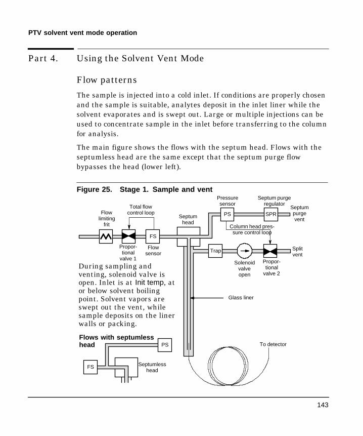
143
PTV solvent vent mode operation
Part 4. Using the Solvent Vent Mode
Flow patterns
The sample is injected into a cold inlet. If conditions are properly chosenand the sample is suitable, analytes deposit in the inlet liner while thesolvent evaporates and is swept out. Large or multiple injections can beused to concentrate sample in the inlet before transferring to the columnfor analysis.
The main figure shows the flows with the septum head. Flows with theseptumless head are the same except that the septum purge flowbypasses the head (lower left).
Figure 25. Stage 1. Sample and vent
Solenoidvalveopen
Propor-tional
valve 2
Trap
To detector
Total flowcontrol loop
Flowsensor
Propor-tional
valve 1
Flowlimiting
frit Column head pres-sure control loop
Pressuresensor
Septum purgeregulator
PS SPR
Glass liner
FS
During sampling andventing, solenoid valve isopen. Inlet is at Init temp, ator below solvent boilingpoint. Solvent vapors areswept out the vent, whilesample deposits on the linerwalls or packing.
Septumpurgevent
Splitvent
PS
FS Septumlesshead
Flows with septumlesshead
Septumhead

144
PTV solvent vent mode operation
Stage 2. Sample transfer
Solenoidvalveclosed
Propor-tional
valve 2
Trap
To detector
Flowsensor
Propor-tional
valve 1
Flowlimiting
frit
Column head pressure controlloop
Pressuresensor
Septum purgeregulator
PS SPR
Glass liner
FS
When solvent venting ends,solenoid valve closes and in-let heats to Final temp 1.The sample transfers to thecapillary column.
Septumpurgevent
Splitvent
PS
FS Septumlesshead
Flows with septumlesshead
Septumhead
Stage 3. Purge and cleanup
The solenoid valve opens again and the system returns to the Stage 1configuration but with different setpoints. The PTV inlet is flushed.Additional ramp rates are available to thermally clean the inlet or toreduce inlet temperature after sample transfer. This can extend the lifeof the liner.

145
PTV solvent vent mode operation
Temperature, pressure, and flow considerations
The solvent vent mode goes through three distinct pneumatic states;venting, sample transfer, and purging. The vent portion allows the inletpressure and the vent flow to to be adjusted to optimize solventelimination. The transfer state mimics traditional splitless operation andtransports the analytes from the liner to the column. The purging modeallows the user to prepare the inlet for the next run.
A fundamental difficulty with solvent vent mode is the potential loss ofvolatile analytes with the solvent. Several solutions are possible for thissituation:
- The inlet liner can be packed with a more retentive material, such asTenax. This greatly improves volatile analyte recovery but mayimpact recovery of higher boiling materials.
- Some of the solvent can be left in the liner when sample transferbegins. The residual solvent acts like a stationary phase and retainsvolatile material, but at the expense of a larger solvent peak.
- The inlet temperature can be reduced. This reduces the vaporpressure of the volatile analytes and permits higher recoveries.
Solvent removal can be speeded up by:
- Reducing pressure in the inlet during sample introduction—the Ventpressure parameter
- Increasing flow through the inlet—the Vent flow parameter
While all these possibilities do complicate use of the PTV, they provideincreased flexibility and new potential to solve difficult problems.
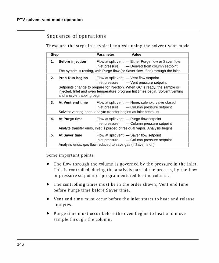
146
PTV solvent vent mode operation
Sequence of operations
These are the steps in a typical analysis using the solvent vent mode.
Step Parameter Value
1. Before injection Flow at split vent — Either Purge flow or Saver flowInlet pressure — Derived from column setpoint
The system is resting, with Purge flow (or Saver flow, if on) through the inlet.
2. Prep Run begins Flow at split vent — Vent flow setpointInlet pressure — Vent pressure setpoint
Setpoints change to prepare for injection. When GC is ready, the sample isinjected. Inlet and oven temperature program Init times begin. Solvent ventingand analyte trapping begin.
3. At Vent end time Flow at split vent — None, solenoid valve closedInlet pressure — Column pressure setpoint
Solvent venting ends, analyte transfer begins as inlet heats up.
4. At Purge time Flow at split vent — Purge flow setpointInlet pressure — Column pressure setpoint
Analyte transfer ends, inlet is purged of residual vapor. Analysis begins.
5. At Saver time Flow at split vent — Saver flow setpointInlet pressure — Column pressure setpoint
Analysis ends, gas flow reduced to save gas (if Saver is on).
Some important points
- The flow through the column is governed by the pressure in the inlet.This is controlled, during the analysis part of the process, by the flowor pressure setpoint or program entered for the column.
- The controlling times must be in the order shown; Vent end timebefore Purge time before Saver time.
- Vent end time must occur before the inlet starts to heat and releaseanalytes.
- Purge time must occur before the oven begins to heat and movesample through the column.
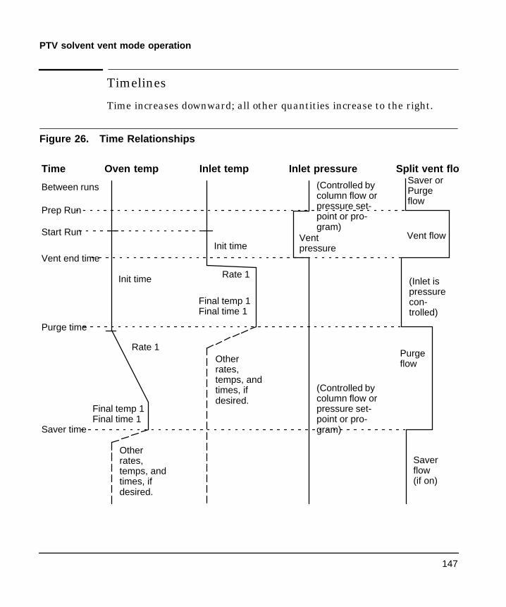
147
PTV solvent vent mode operation
Timelines
Time increases downward; all other quantities increase to the right.
Figure 26. Time Relationships
(Controlled bycolumn flow orpressure set-point or pro-gram)
Time Oven temp Inlet temp Inlet pressure
Start Run
Init time
Init time
Prep Run
Vent end time
Purge time
Saver time
Split vent flow
Between runsSaver orPurgeflow
Saverflow(if on)
Purgeflow
Vent flow
(Inlet ispressurecon-trolled)
Ventpressure
(Controlled bycolumn flow orpressure set-point or pro-gram)
Rate 1
Final temp 1Final time 1
Rate 1
Final temp 1Final time 1
Otherrates,temps, andtimes, ifdesired.
Otherrates,temps, andtimes, ifdesired.

148
PTV solvent vent mode operation
When is Start Run?
Both the inlet and oven temperature programs begin at Start Run. Alltimes—such as Purge time—are measured from Start Run. When doesStart Run occur?
- If the sample is injected manually, Start Run occurs when the userpresses the Start Run key.
- If a single injection per run is made using an autosampler, Start Runoccurs when the syringe carrier moves down to make the injection.
- If multiple injections per run are made using an autosampler, StartRun occurs when the syringe carrier moves down to make the firstinjection of the set. There are no Start Run signals for the rest of theinjections in the set.
These additional injections take time. The inlet and oventemperature programs, mainly the Init time values, must be adjustedto allow for this. So must the various time values that control theinlet operation. This is discussed in more detail under Large Volumeinjections, later in this chapter.

149
PTV solvent vent mode operation
Control table parameters—solvent vent operation
Mode: The current operating mode—solvent vent
Temp Actual and setpoint initial inlet temperatures
Init time The time, measured from Start Run, when the initial inlettemperature hold ends. Usually greater than Vent end time.
Rate # Temperature program rate for inlet thermal ramps 1, 2, and 3.
Final temp # Final inlet temperature for ramps 1, 2, and 3.
Final time # Hold time at Final temp 1, 2, and 3. This time is aduration; it is not measured from Start Run.
Pressure Actual and setpoint inlet pressure before and after the ventperiod. It sets the starting point of column head pressure.
Vent pressure The inlet pressure during the vent period. By decreasingthe inlet pressure while venting, solvent elimination proceeds faster.Also, the pressure reduction decreases the amount of carrier gas—andsolvent vapor—that enters the column during this time.
Users select from 0 to 100 psig. If 0 is chosen, the inlet uses the lowestpressure possible at the given vent flow. Table 17 shows approximatevalues for this minimum at various vent flows of helium. Pressures lessthan those in the table are not possible unless the flow is reduced.
Table 17. Minimum attainable pressures
Vent flow(mL/min)
Actual vent pres-sure at “0“ psigsetpoint
Actual vent pres-sure at “0” kPasetpoint
50 0.7 5
100 1.3 10
200 2.6 18
500 6.4 44
1000 12.7 88

150
PTV solvent vent mode operation
Vent flow The flow of carrier gas out the split vent during the ventperiod. Higher flows sweep the liner more quickly and reduce the timefor solvent elimination. For most columns, 100 mL/min vent floweliminates solvent at an acceptable rate but puts minimal material onthe column.
Vent end time The time, measured from Start Run, when solventventing ends. For large volume injections, this time is normally greaterthan the time for the injection to complete.
Purge time The time, measured from Start Run, when sample transferends. It began at Vent end time.
Purge flow The flow of carrier gas to the inlet beginning at Purge time.
Total flow The Total flow displays the actual flow to the inlet.
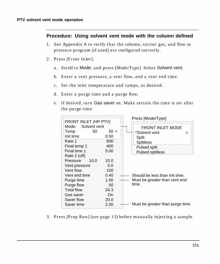
151
PTV solvent vent mode operation
Procedure: Using solvent vent mode with the column defined
1. See Appendix A to verify that the column, carrier gas, and flow orpressure program (if used) are configured correctly.
2. Press [Front Inlet].
a. Scroll to Mode: and press [Mode/Type]. Select Solvent vent.
b. Enter a vent pressure, a vent flow, and a vent end time.
c. Set the inlet temperature and ramps, as desired.
d. Enter a purge time and a purge flow.
e. If desired, turn Gas saver on. Make certain the time is set afterthe purge time.
FRONT INLET (HP PTV)Mode: Solvent ventTemp 50 50 <Init time 0.50Rate 1 600Final temp 1 400Final time 1 5.00Rate 2 (off)Pressure 10.0 10.0Vent pressure 5.0Vent flow 100Vent end time 0.40Purge time 1.50Purge flow 50Total flow 24.3Gas saver OnSaver flow 20.0Saver time 2.00
Press [Mode/Type]
Must be greater than vent endtime.
FRONT INLET MODE*Solvent vent <SplitSplitlessPulsed splitPulsed splitless
Should be less than Init time.
Must be greater than purge time.
3. Press [Prep Run] (see page 13) before manually injecting a sample.

152
PTV solvent vent mode operation
Procedure: Using solvent vent mode with the column notdefined
1. See Appendix A to verify that the column, carrier gas, and flow orpressure program (if used) are configured correctly.
2. Press [Front Inlet].
a. Scroll to Mode: and press [Mode/Type]. Select Solvent vent.
b. Enter a vent end time and a vent pressure.
c. Set the inlet temperature and ramps, as desired.
d. Enter a purge time. It must be greater than the vent end time.
e. Set total flow greater than the column flow plus the septum purgeflow (about 6 mL/min) to guarantee adequate column flow.
FRONT INLET (HP PTV)Mode: Solvent ventTemp 50 50 <Init time 0.50Rate 1 600Final temp 1 400Final time 1 5.00Rate 2 (off)Pressure 10.0 10.0Vent pressure 5.0Vent end time 0.40Purge time 1.50Tot flow 20.0 20.0
Press [Mode/Type]
FRONT INLET MODE*Solvent vent <SplitSplitlessPulsed splitPulsed splitless
Must be greater than vent endtime.
Should be less than Init time.
3. Press [Prep Run] (see page 13) before manually injecting a sample.

153
PTV solvent vent mode operation
Large volume injectionMost vaporizing inlets are designed for liquid injections in the 1 to 5 ³L range.With larger injections, the vapor cloud created when the sample vaporizes mayoverflow the inlet and degrade the chromatography. For the PTV, the nominalliner liquid capacities are:
Table 18. Liner capacities
Liner Nominal liquid capacity Inertness
Open baffle 5 ³L High
Glass woolpacked
25 ³L Lower, because of greater surfacearea
In the solvent vent mode, analytes are thermally trapped in the liner while thesolvent is removed. With the solvent gone, the liner volume can be used foranother injection. Injection can be repeated several times to concentrate theanalytes from a large sample volume. After injection and solvent removal, theanalytes are transferred to the column. This can replace the need for offlineconcentrating and minimize loss of sample.
Multiple injections by an automatic sampler can be used with the PTV toachieve large volume injection. A ChemStation controls the process.
Gas chromatograph requirements
- Model 6890 GC with A.2.00 or later firmware
- HP PTV
Automatic sampler requirements
- Model G1512A controller with G1512A.01.08 or later firmware.
- Model G1513A injector with G1513A.09.14 or later firmware. A secondinjector can be mounted for synchronous injections to the rear inlet, but onlyone PTV can be mounted and it must be in the front position.
Use of the 18593A or 18593B injection tower may damage the system.
- Operates with or without sample tray, and with either standard or 8-sampleturret.
Caution

154
PTV solvent vent mode operation
ChemStation requirements
A GC or MSD ChemStation is necessary for multiple injection becausethe needed parameters are not available through the HP 6890 GCkeyboard.
- GC ChemStation Software revision A.04.02 or lateror Software revision A.04.01 plus the software
provided with the PTV.
- MSD ChemStation Software revision A.03.00 or later
Control parameters—Injector configuration subscreen
Parameter Range Default
Syringe size 0.1 to 100 ³L 10 ³L
Nanoliter Adapter Present or not present Not present
Multiple Injections Single or Multiple Single
- Syringe size Full volume of the syringe.
- Nanoliter Adapter Controlled by a checkbox. If checked, indicatesthat a nanoliter adapter is present on the injector. If not checked,means that a nanoliter adapter is not present on the injector.
- Multiple Injections Controlled by a checkbox.If checked, the samplermakes multiple injections into the inlet for each run according to theother parameters. It issues a Start Run command at the firstinjection only.
If not checked, the sampler makes one injection—and issues a StartRun command—for each run. This is the default mode of operation.

155
PTV solvent vent mode operation
Control parameters—Injector screen
Parameter Range Default
Inject X ³L Y times X: 0.1 to 0.5 x syringe volumeY: 1 to 100
X: 0.1 x syringe volumeY: 1
Delay between injections 0 to 100 seconds 0
Preinjection washes 0 to 15 0
Postinjection washes 0 to 15 0
Pumps 0 to 15 0
- Inject X ³L Y times X is the amount to be injected; Y is the number ofinjections to make. If the nanoliter adapter is checked on the InjectorConfiguration screen, the range becomes 0.02 to 0.4 x syringe volume.
- Delay A pause time, in seconds, between injections. This is added to theminimum hardware cycle time.
- Preinjection washes Number of times to wash the syringe with solventand/or sample before the first injection. No washes are performed before therest of the injections in a multiple injection set.
- Postinjection washes Number of times to wash the syringe with solventafter the last injection. No washes are performed after the rest of theinjections in a multiple injection set.
- Preinjection pumps Number of times to pump the syringe plunger beforedrawing up the measured sample. Pump are performed only before the firstinjection of a multiple injection set.
Calculated values
The software calculates and displays:
- On the Injector screen: Total Product of X (Volume per injection) and Y(Injections per run).
- On the Inlets screen: Estimated total injection time The approximate totaltime, in minutes, to make a set of multiple injections based on theparameters entered and the mechanical cycle time of the sampler. IncludesDelay between injections, pre- and post-injection dwell times, and viscositydelays.
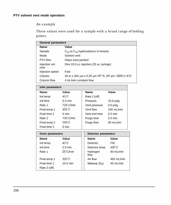
156
PTV solvent vent mode operation
An example
These values were used for a sample with a broad range of boilingpoints.
General parameters
Name Value
Sample C10 to C44 hydrocarbons in hexane
Mode Solvent vent
PTV liner Glass wool packed
Injection vol-ume
One 10.0 ³L injection (25 ³L syringe)
Injection speed Fast
Column 30 m x 320 ³m x 0.25 ³m +3í�� HP p/n �����-í���
Column flow 4 mL/min constant flow
Inlet parameters
Name Value Name Value
Init temp ��Û& Rate 2 (off)
Init time 0.3 min Pressure 15.6 psig
Rate 1 ���Û&�PLQ Vent pressure 0.0 psig
Final temp 1 ���Û& Vent flow 100 mL/min
Final time 1 5 min Vent end time 0.2 min
Rate 2 ���Û&�PLQ Purge time 2.0 min
Final temp 2 ���Û& Purge flow 50 mL/min
Final time 2 0 min
Oven parameters Detector parameters
Name Value Name Value
Init temp ��Û& Detector FID
Init time 2.5 min Detector temp ���Û&
Rate 1 ��Û&�PLQ Hydrogenflow
40 mL/min
Final temp 1 ���Û& Air flow 450 mL/min
Final time 1 10.0 min Makeup (N2) 45 mL/min
Rate 2 (off)

157
PTV solvent vent mode operation
Figure 27. Chromatogram From One 10 L Injection
C20
These results were compared with a splitless analysis of the samesample, which should produce 100% recovery of all analytes. The datashowed that, under these conditions, compounds above C20 werecompletely recovered and that the recovery was independent of injectionsize; Compounds lower than C20 were partially vented with the solvent.

158
PTV solvent vent mode operation
Possible adjustments
Depending on what you are trying to accomplish, you have a number ofpossible adjustments available.
- To eliminate more solvent
J Increase the vent end time, inlet initial time, and purge time.This will not affect analytes that are quantitatively trapped butwill eliminate more of the solvent peak.
J Increase the vent flow to sweep the liner more rapidly with thesame inlet timing. Increasing vent flow raises vent pressure if itis set to 0. This puts more solvent onto the column.
J Raise the inlet initial temperature to vaporize more solvent andallow more to be eliminated. This also increases the loss ofvolatile analytes since their vapor pressures also increase.
- To improve recovery of low boiling analytes
J Reduce inlet temperature to lower the vapor pressure of theanalytes and trap them more effectively. This also reduces solventvapor pressure and more time will be needed to eliminate it.
J Use a retentive packing in the liner. Materials such as Tenaxpermit higher recovery of volatile analytes but may not releasehigher boiling compounds. This must be considered if quantitationon these high boiling peaks is desired.
J Leave more solvent in the liner. The solvent acts as a pseudostationary phase and helps retain volatile analytes. This must bebalanced against the detector’s tolerance for solvent.
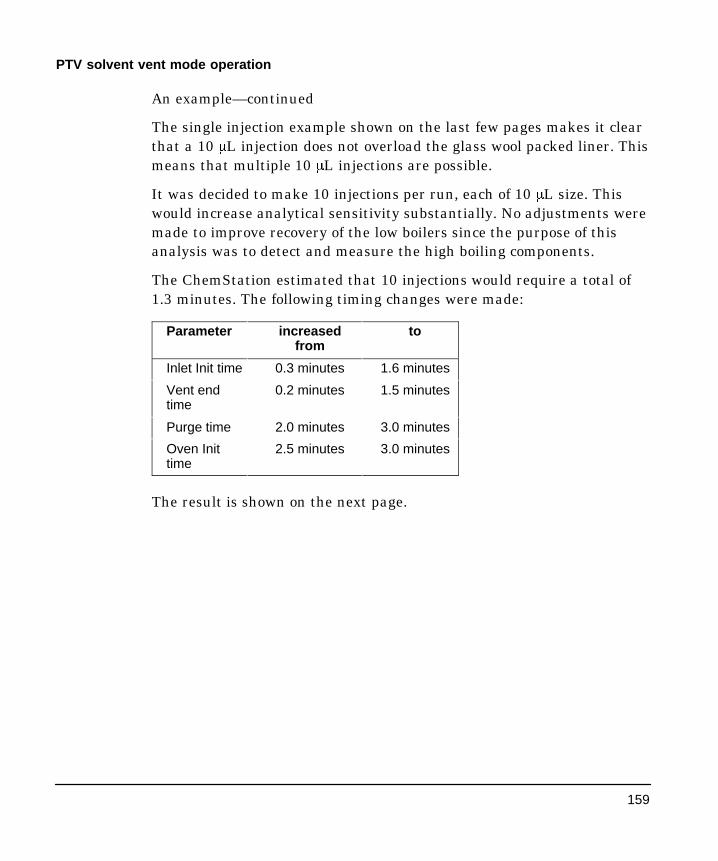
159
PTV solvent vent mode operation
An example—continued
The single injection example shown on the last few pages makes it clearthat a 10 ³L injection does not overload the glass wool packed liner. Thismeans that multiple 10 ³L injections are possible.
It was decided to make 10 injections per run, each of 10 ³L size. Thiswould increase analytical sensitivity substantially. No adjustments weremade to improve recovery of the low boilers since the purpose of thisanalysis was to detect and measure the high boiling components.
The ChemStation estimated that 10 injections would require a total of1.3 minutes. The following timing changes were made:
Parameter increasedfrom
to
Inlet Init time 0.3 minutes 1.6 minutes
Vent endtime
0.2 minutes 1.5 minutes
Purge time 2.0 minutes 3.0 minutes
Oven Inittime
2.5 minutes 3.0 minutes
The result is shown on the next page.
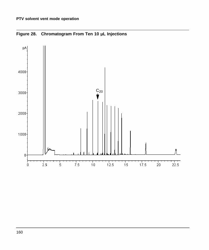
160
PTV solvent vent mode operation
Figure 28. Chromatogram From Ten 10 L Injections
C20

161
PTV maintenance
Part 5. Maintaining a PTV
Inlet adapters
The Graphpack-2M connector (the inlet adapter) at the bottom of theinlet is sized to the column diameter. When a different diameter columnis to be installed, the adapter must be changed.
The adapter number is stamped on the side of the adapters. Select thesmallest hole diameter that will accept the column.
Table 19. Inlet adapters
ColumnID
Inlet adapternumber
Quanti-ty
HP part num-ber
200 ³m 31 1 ����í����
250 ³m 45 1 ����í����
320 ³m 45 1 ����í����
530 ³m 70 1 ����í����
Procedure: Replacing inlet adapters
1. Unscrew the column nut from the adapter. Remove the nut and thecolumn from the inlet.
2. With a 6 mm wrench, remove the inlet adapter, being careful not tolose the silver seal inside. Save the adapter for later use.
3. Select the appropriate inlet adapter for the column to be installed.Insert a new silver seal (part number 51829763, pkg of 5) into theadapter and screw the adapter onto the inlet fingertight. Use the 6mm wrench to tighten the adapter an additional 1/16 to 1/8 turn.
Do not overtighten the adapter. The inlet can be damaged if theadapter is forced. If the adapter leaks, check the silver seal andreplace it if necessary.

162
PTV maintenance
Procedure: Installing columns
Graphpack-2M ferrules are sized to the column outer diameter.
Table 20. Columns and ferrules
Col-umn ID
Graphpack fer-rule hole ID
Quanti-ty
HP part num-ber
200 ³m 0.31 mm 10 ����í����
250 ³m 0.40 mm 10 ����í����
320 ³m 0.45 mm 10 ����í����
530 ³m 0.70 mm 10 ����í����
1. Place the appropriate Graphpack ferrule onto the column inlet endand pull it at least 30 mm from the end.
2. With a glass knife or other fused silica cutter, remove approximately10 mm from the column end to eliminate graphite contamination.
3. Position the ferrule so that it is 17 mm from the column end. Place asmall mark (typewriter correction fluid is useful) at the back of theferrule and, making sure that the column is correctly positioned,insert the column end into the adapter.
2
0
22
cm 17 mm
Mark column here

163
PTV maintenance
4. Screw the column nut on fingertight. Using a 5 mm wrench, tightenthe column nut 1/8 to 1/4 turn. Be careful not to overtighten.
5. Check the connections for leaks. If there are any leaks at the columnadapter, tighten it slightly more with the open end wrench provided.

164
PTV maintenance
The septumless head
This sampling head uses a check valve instead of a septum to seal thesyringe entrance passage. It may be used with either automatic ormanual injection. Syringes must have 23 gauge needles (see the lastpage of this chapter).
Procedure: Removing the septumless head
1. Cool the inlet to room temperature.
2. Disconnect the carrier gas line.
3. Unscrew the septumless head counterclockwise from the inlet.
4. Screw the new head onto the inlet. Tighten it 1/8 turn past fingertight.
Carrier gas connection
5. Reconnect the carrier gas line.
6. Check all connections on the sampling head for leaks. If necessary,tighten them again by hand.

165
PTV maintenance
Procedure: Cleaning the septumless head
Minor deposits from sample mixtures can collect in the head. Dust andabraded material particles can enter together with the syringe needle,eventually causing leaks. We recommend periodic cleaning.
1. Cool the inlet to room temperature.
2. Disconnect the carrier gas line and unscrew the head from the inlet.
3. Unscrew the sealing element from the head. Carefully remove theViton seal and the pressure spring. Do not use a sharp object toextract the valve body—this can leave scratches that cause leaks.
Guide cap
Teflon ferrule, �������
Kalrez seal, �������Valve body, �������
Pressure spring, �������
Viton seal, �������
Sealing element, �������
Carrier gas line
4. Unscrew the guide cap from the head and remove the Teflon ferrule.
5. Insert a syringe with a 23 gauge needle carefully into the head topress the valve body with the Kalrez seal slightly out of the head.Carefully tap the head on a soft smooth surface so that the valvebody falls out completely or slips so far out that you can grasp it withyour fingers.

166
PTV maintenance
6. Remove the seal from the valve body.
7. Carefully clean all components in hexane.
8. Assemble the head in reverse order. Make sure that you workabsolutely lint-free and that the seals and the pressure spring are notdamaged.
9. Use this opportunity to check the Teflon ferrule. If it must bereplaced, see page 167 for instructions.
10. Check the entire system again for leaks; if necessary, carefullyretighten the guide cap slightly more with the syringe needle insertedand/or replace the Kalrez seal.
If the head leaks when a syringe is inserted, the Teflon ferrule is theproblem. If the head leaks without a syringe inserted, the seals mayneed to be replaced.

167
PTV maintenance
Procedure: Replacing the Teflon ferrule
1. Unscrew the guide cap from the septumless head and remove theTeflon ferrule.
2. Push the guide cap and the new Teflon ferrule over the syringeneedle so that at least 10 mm of the needle tip is exposed.
3. Guide the end of the syringe needle into the septumless head untilthe ferrule meets the septumless head.
4. Tighten the guide cap until resistance is first felt.
5. Check for leaks when the syringe needle has been fully introduced.
6. If necessary, carefully tighten the guide cap until the inlet stopsleaking.

168
PTV maintenance
The septum head
The septum head uses either a regular septum or a Merlin microseal toseal the syringe passage. A stream of gas sweeps the inner side of theseptum and exits through the septum purge vent on the pneumaticsmodule.
Retaining nut
169
PTV maintenance
Procedure: Removing the septum head
The septum head connects to the inlet via a free-spinning retaining nut.
1. Cool the inlet to room temperature.
2. Use a 5/8 in. wrench to loosen the retaining nut on the septum head.
3. Gently remove the septum head assembly from the inlet. Be carefulnot to overly bend the 1/16 inch lines. For best results, lift the head toclear the inlet and then push it to either side to allow access.
4. To reinstall the septum head, gently align the head with the inletand manually engage the free-spinning nut to the inlet.
The nut should easily turn on to the inlet. If resistance is felt,unscrew the nut and retry. Excessive force can irreparably damagethe inlet.
5. Tighten the retaining nut ½ turn past finger tight.
6. Check all connections for leaks. If necessary, the retaining nut can betightened an additional ¼ of a turn to eliminate leaks.

170
PTV maintenance
Procedure: Changing the septum
Either a regular septum or a Merlin microseal can be used with theseptum head.
If the inlet temperature is set below 40C, the Merlin microseal may notseal effectively. For inlet temperatures below 40C, use a regularseptum for the inlet seal.
1. To replace the septum, cool the inlet to ambient temperature.
2. Using the inlet tool or manually, unscrew the septum cap or Merlincap counterclockwise. If the septum head begins to turn, support itmanually while removing the cap.
3. Remove the septum or Merlin microseal, taking care not to scratchthe interior of the septum head.
4. Install a new septum or Merlin microseal and the correct cap. Wheninstalling a Merlin microseal, note that the side where the metalparts are visible goes down.
Merlinmicro-seal andcap
Standardseptumand cap
5. Check for leaks out of the cap and tighten the cap if necessary.

171
PTV maintenance
Glass inlet liners
The liner is the chamber for sample deposition. Three kinds areavailable:
Table 21. Inlet liners
Type Injection capacity Inertness Quantity HP part num-ber
Open baffled liner lowest capacity most inert 10 �������
Liner packed withsilanized glasswool
higher capacity less inert 10 �������
Unpacked liner, tobe packed by theuser
depends on the packing 10 �������

172
PTV maintenance
Procedure: Replacing liners
1. Remove the head from the inlet See page 164 (septumless head) or169 (septum head).
2. Grasp the liner by the Graphpack ferrule. Remove the liner andferrule.
3. Unscrew the assembly tool (HP part number G261780540) into twopieces, the ferrule guide and the compression fitting.
Ferrule guide
Graphpack-3D ferrule
Compressionfitting
Open baffle liner
4. Slide the compression fitting onto the longer straight end of the newliner with the threads pointing toward the end of the liner.
5. Place a Graphpack-3D ferrule on the same end of the the liner withthe recessed graphite end towards the compression fitting. Slide theferrule on so that about 2 mm of liner is exposed beyond the ferrule.
6. Slide the compression fitting up to meet the ferrule. Screw the ferruleguide gently onto the compression fitting until it is fingertight.

173
PTV maintenance
7. Unscrew and remove the ferrule guide. Slide the compression fittingoff the other end of the liner. The ferrule should now be set with 1mm of liner exposed. Check that the graphite within the ferrule isflush with the top of the metal collar.
8. Insert the glass liner into the inlet from above until the unpackedside of the ferrule rests on the top of the inlet.
9. Replace the sampling head and reconnect the lines, if necessary.
10. Check all connections for leaks. If necessary, tighten them again byhand.
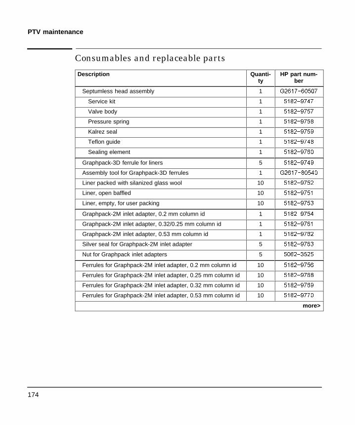
174
PTV maintenance
Consumables and replaceable parts
Description Quanti-ty
HP part num-ber
Septumless head assembly 1 *��������
Service kit 1 �������
Valve body 1 �������
Pressure spring 1 �������
Kalrez seal 1 �������
Teflon guide 1 �������
Sealing element 1 �������
Graphpack-3D ferrule for liners 5 �������
Assembly tool for Graphpack-3D ferrules 1 *��������
Liner packed with silanized glass wool 10 �������
Liner, open baffled 10 �������
Liner, empty, for user packing 10 �������
Graphpack-2M inlet adapter, 0.2 mm column id 1 �������
Graphpack-2M inlet adapter, 0.32/0.25 mm column id 1 �������
Graphpack-2M inlet adapter, 0.53 mm column id 1 �������
Silver seal for Graphpack-2M inlet adapter 5 �������
Nut for Graphpack inlet adapters 5 �������
Ferrules for Graphpack-2M inlet adapter, 0.2 mm column id 10 �������
Ferrules for Graphpack-2M inlet adapter, 0.25 mm column id 10 �������
Ferrules for Graphpack-2M inlet adapter, 0.32 mm column id 10 �������
Ferrules for Graphpack-2M inlet adapter, 0.53 mm column id 10 �������
more>
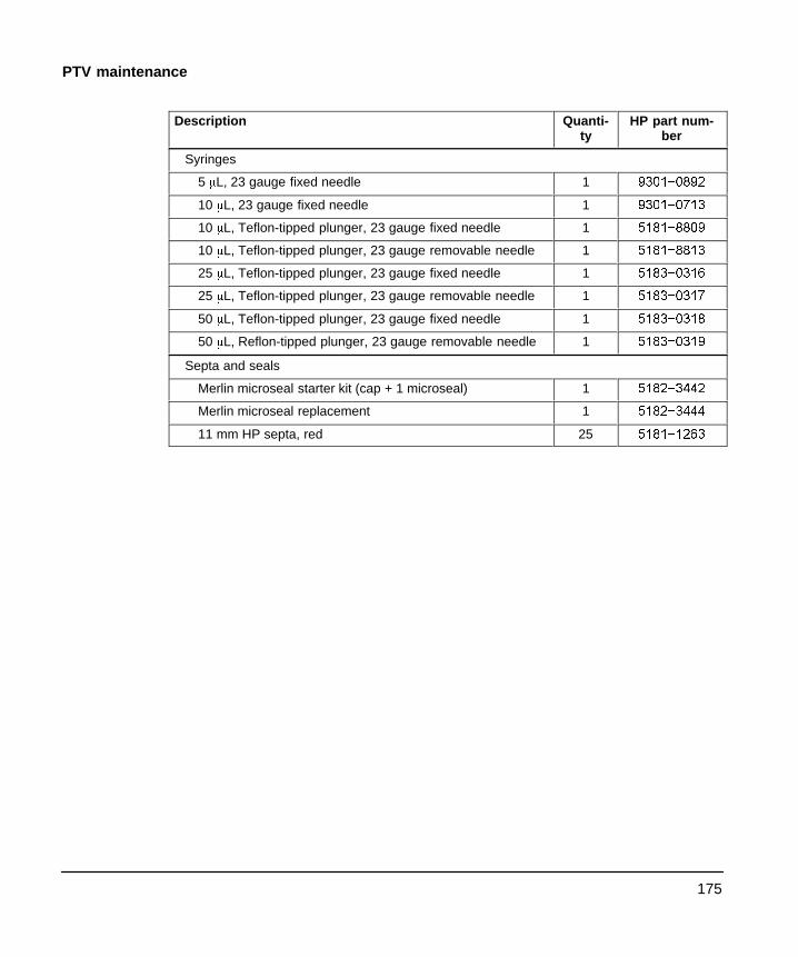
175
PTV maintenance
Description Quanti-ty
HP part num-ber
Syringes
5 ³L, 23 gauge fixed needle 1 ����í����
10 ³L, 23 gauge fixed needle 1 ����í����
10 ³L, Teflon-tipped plunger, 23 gauge fixed needle 1 ����í����
10 ³L, Teflon-tipped plunger, 23 gauge removable needle 1 ����í����
25 ³L, Teflon-tipped plunger, 23 gauge fixed needle 1 ����í����
25 ³L, Teflon-tipped plunger, 23 gauge removable needle 1 ����í����
50 ³L, Teflon-tipped plunger, 23 gauge fixed needle 1 ����í����
50 ³L, Reflon-tipped plunger, 23 gauge removable needle 1 ����í����
Septa and seals
Merlin microseal starter kit (cap + 1 microseal) 1 �������
Merlin microseal replacement 1 �������
11 mm HP septa, red 25 �������

6
The Volatiles Interface
Part 1. Using a Volatiles InterfaceSplit mode, 180
Understanding the pneumatics, 180Procedure: Split mode, column defined, 185Procedure: Split mode, column not defined, 186
Splitless mode, 187Understanding the pneumatics, 187Procedure: Splitless mode, 193
Direct mode, 194Understanding the pneumatics, 194Preparing for direct sample introduction, 196Procedure: Disconnect split vent line, 196Procedure: Configure GC for direct injection, 198Procedure: Direct mode, 202
Part 2. Maintaining a Volatiles InterfaceProcedure: Installing columns, 204Procedure: Replacing/cleaning the interface, 208Procedure: Leak checking gas plumbing, 211Procedure: Leak checking, 212Procedure: Preparing for a leak test, 215Procedure: Correcting leaks, 216
Part 3. Connecting to an External Gas SamplerConnecting the HP 7694 headspace sampler, 218Connecting the HP 7695 purge and trap concentrator, 221
178
Chapter 6.The Volatiles Interface
Part 1. Using a Volatiles Interface
The volatiles interface provides a simple, reliable way to introduce a gassample into your gas chromatograph (GC) from an external device suchas the headspace, purge and trap, or air toxics samplers. The interfacehas a small volume and is highly inert, thus ensuring high sensitivityand resolution for applications requiring trace level detection.
Total flow to the interface is measured by a flow sensor and is dividedinto two streams. One stream connects to the septum purge regulator;the other connects to a frit block. At the frit block, the flow is furtherdivided. The first stream goes to the gas-phase sampler and from there isintroduced into the interface. The second stream, called the pressuresensing line, passes through the frit block and is measured by a pressuresensor. This stream also provides a trickle flow to the interface.
There are three modes of operation—split, splitless, and direct. Thepneumatics vary for each operating mode and are discussed in detaillater in this chapter. Table 22 summarizes some issues to consider whenchoosing an operating mode. Specifications for the interface are alsolisted.

Volatiles interface
179
Operation
Table 22. Overview of volatiles interface
Mode Sample type(Concentration)
Sample tocolumn
Comments
Split High Very little,most isvented
Splitless Low All Can switch to split modeelectronically.
Direct Low All Must physically disconnect splitvent, plug the interface, andreconfigure the GC. Maximizessample recovery andeliminates possibility ofcontamination to pneumaticsystem.
Specifications
SilcosteelX-treated flow path
Volume: 32 mL
Internal dimensions: 2 mm by 10 mm
Maximum total flow to interface: 100 mL/min
Split range: Dependent on column flowTypically no split to 100:1
Temperature range: 10EC above ambient (with ovenat ambient) to 400EC
Recommended temperature: | transfer line temperature ofthe external sampling device
Volatiles Interface
180
Split mode
Split mode
When you introduce a sample in the split mode, a small amount of thesample enters the column while the major portion exits from the splitvent. The ratio of split flow to column flow is controlled by the user. Thesplit mode is primarily used for high concentration samples when youcan afford to lose most of the sample out the split vent and for samplesthat cannot be diluted.
Understanding the pneumatics
During Pre Run, during sampling, and after sampling, total flow to theinterface is measured by a flow sensor and controlled by a proportionalvalve. Flow at the head of the column is back-pressure regulated.Pressure is sensed upstream from the proportional valve.

Volatiles interface
181
Split mode
Figure 29. Pneumatics: Split modeSplitless mode: Idle or after sampling end
Total flowcontrolloop
Todetector
PS
Carriersupply
Columnhead
pressurecontrol loop
FS
PS
SPRFlow sensor
Pressuresensor
Septum purge regulator
Proportional valve
Split
vent
Solenoidvalveopen
Frit block(pressure sensing line)
FS SPR
Gas phasesampler
Trap

Volatiles Interface
182
Split mode
Using the control table
Mode: The current operating mode—split
Temp Actual and setpoint interface temperatures
Pressure Actual and setpoint interface pressure
Split ratio The ratio of split flow to column flow. Column flow is set atthe Column 1 or Column 2 control table. This parameter is not availableif your column is not defined.
Split flow Flow, in mL/min, from the split vent. This parameter is notavailable if your column is not defined.
Total flow The total flow into the interface, both setpoint and actual.
BACK INLET (VI)Mode: SplitTemp 250 250 <Pressure 10.0 10.0Split ratio 100Split flow 76.6Tot flow 80.3 80.3Gas saver OnSaver flow 20.0Saver time 2.00
Column defined
BACK INLET (VI)Mode: SplitTemp 250 250 <Pressure 10.0 10.0Tot flow 79.1 79.1
Column not defined
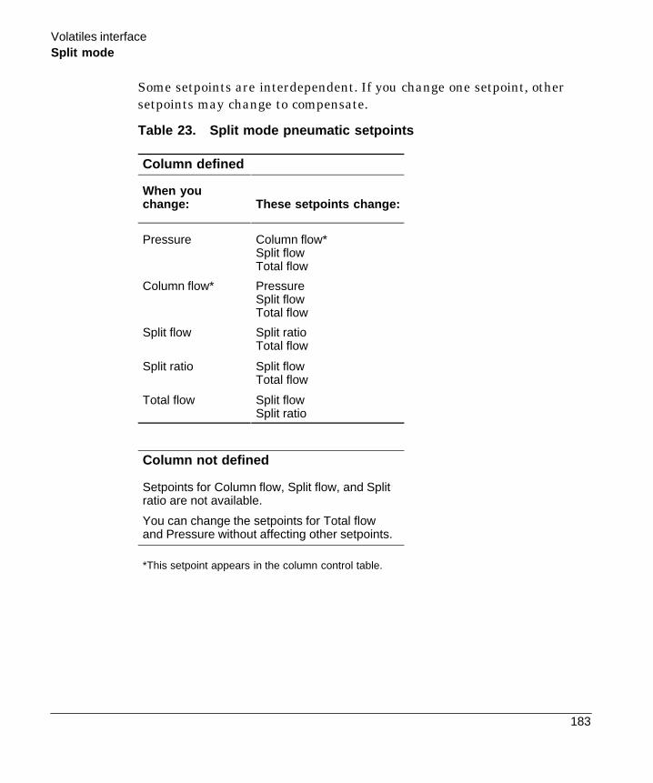
Volatiles interface
183
Split mode
Some setpoints are interdependent. If you change one setpoint, othersetpoints may change to compensate.
Table 23. Split mode pneumatic setpoints
Column defined
When youchange: These setpoints change:
Pressure Column flow*Split flowTotal flow
Column flow* PressureSplit flowTotal flow
Split flow Split ratioTotal flow
Split ratio Split flowTotal flow
Total flow Split flowSplit ratio
Column not defined
Setpoints for Column flow, Split flow, and Splitratio are not available.
You can change the setpoints for Total flowand Pressure without affecting other setpoints.
*This setpoint appears in the column control table.

Volatiles Interface
184
Split mode
Operating parameters
Use the information in Table 24 to help you set up the operatingconditions for your interface.
Table 24. Split mode operating parameters
Parameter Allowed Setpoint Range Suggested StartingValue
Oven initial time 0 to 999.9 minutes After sample on column
Interfacetemperature
Ambient + 10EC to 400EC | transfer linetemperature
Gas saver time 0 to 999.9 minutes After sample on column
Gas saver flow 15 to 100 mL/min 15 mL/min greater thanmaximum column flow
Split ratio
Because of the interface’s small internal volume, the maximum total flow to theinterface is 100 mL/min. This maximum flow puts some restriction on the split ratioyou can set:
Column diame-ter
Column flow Maximum splitratio
Total flow
200 mm 1 mL/min 100:1 100 mL/min
530 mm 5 mL/min 20:1 100 mL/min

Volatiles interface
185
Split mode
Procedure: Operating in the split mode with the column defined
1. Verify that the split vent line is connected to your interface. Verifythat the [Config][Inlet] control table displays “split plumbed.”
2. See Appendix A to verify that the column, carrier gas, and flow orpressure program (if used) are configured correctly.
3. Press [Front Inlet] or [Back Inlet].
BACK INLET MODESplit <
*Splitless
Press [Mode/Type]BACK INLET (VI)
Mode: SplitTemp 250 250 <Pressure 10.0 10.0Split ratio 100Split flow 76.6Tot flow 80.3 80.3Gas saver OnSaver flow 20.0Saver time 2.00
a. Scroll to Mode: and press [Mode/Type]. Select Split.b. Set the interface temperature.c. If you want a specific split ratio, scroll to Split ratio and enter that
number. The split flow will be calculated and set for you.d. If you want a specific split flow, scroll to Split flow and enter that
number. The split ratio will be calculated and set for you.e. If desired, turn on Gas saver. Set the Saver time after the sample
has been introduced.f. If gas saver is on, be certain Auto prep run is On (see page 13) or
use the [Prep Run] key before introducing the sample.
Split ratio =Split flow
Column flow

Volatiles Interface
186
Split mode
Procedure: Operating in the split mode with the column notdefined
1. Verify that the split vent is connected to your interface. Verify thatthe [Config][Inlet] control table displays “split plumbed.”
2. See Appendix A to verify that the column, carrier gas, and flow orpressure program (if used) are configured correctly.
3. Press [Front Inlet] or [Back Inlet].
BACK INLET (VI)Mode: SplitTemp 250 250 <Pressure 10.0 10.0Tot flow 79.1 79.1
a. Set the temperature.b. Set total flow into the interface. Measure flow out of the split vent
using a flow meter.c. Subtract the split vent flow from the Total flow. Subtract the
septum purge flow (see “Septum purge” on page 15 for nominalseptum purge flows).
d. Calculate the split ratio. Adjust as needed.
Septum purge
Split vent
Front of GC

Volatiles interface
187
Splitless mode
Splitless mode
When you introduce a sample, the solenoid valve remains closed whilethe sample enters the interface and is transferred to the column. At aspecified time after the sample is introduced, the solenoid valve opens.
Understanding the pneumatics
Before Pre Run, when the GC is preparing for sample introduction, totalflow to the interface is measured by a flow sensor and controlled by aproportional valve. Column flow is controlled via back-pressureregulation. See Figure 29.
During sampling, pressure upsets caused by switching valves in theexternal sampling device can cause fluctuations in column flow rates. Tocompensate for this, the interface is flow controlled during samplingtime. The sampling flow rate is calculated from the pressure setpointthat is active when sample introduction begins. This flow control startswhen the GC goes into the Pre Run state (when your system isautomated and the Pre Run light is on or during manual operation whenyou press [Prep Run]) and ends after the interface’s Sampling endsetpoint expires.
During this user-specified sampling period, the solenoid valve is closed.Flow to the interface is measured by a flow sensor and controlled by aproportional valve. See Figure 30.
After sampling end, the solenoid valve opens. Flow to the interface isagain measured by a flow sensor and controlled by a proportional valvewhile column flow is controlled via back-pressure regulation. The purgeflow is controlled by the user. If desired, gas saver can be turned on atthe end of the run. See Figure 29.

Volatiles Interface
188
Splitless mode
Figure 30. Splitless mode pneumatics: beginning of pre run to sampling end(sample introduction in progress)
Frit block(pressure sensing line)
Total flowcontrol
loop
To detector
FS SPR
PS
Carriersupply
Gasphasesampler
Trap Split vent
FS
PS
SPRFlow sensor
Pressuresensor
Septum purgeregulator
Proportionalvalve
Solenoidvalveclosed
Volatiles interface
189
Splitless mode
Using the control table
Mode: The current operating mode—splitless
Temp Actual and setpoint interface temperatures
Sampl’g end The sample introduction interval, in minutes. The flowrate is calculated from the pressure setpoint that is active at the start ofsample introduction.
Set the sampling end setpoint 0.2 minutes longer than the time thesampler needs to introduce the sample. For example, the HP 7694headspace sampler has an Inject time parameter which controls howlong the valve remains in the inject position. If Inject time is 1 minute,the sampling end setpoint should be set to 1.2 minutes. If you’re usingan HP 7695 Purge and Trap Concentrator, set the Sampling end setpoint0.2 minutes longer than the Desorb time parameter.
If your column is defined and you specify a flow or pressure program foryour column, the ramp does not begin until after the sampling endsetpoint expires.
Pressure Actual and setpoint interface pressure in psi, bar, or kPa.
Purge time The time, after the beginning of the run, when purgingresumes. Purge time must be greater than Sampling end.
Purge flow The flow, in mL/min, from the split vent at Purge time. Youwill not be able access or to specify this value if operating with yourcolumn not defined.

Volatiles Interface
190
Splitless mode
Total flow When your column is defined, Total flow displays the actualflow to the interface. You cannot enter a setpoint. If your column is notdefined, Total flow will have both setpoint and actual values during purgetime. All other times, the actual flow to the interface is displayed.
BACK INLET (VI)Mode: SplitlessTemp 250 250 <Sampl’g end 1.00Pressure 10.0 10.0Purge time 4.00Purge flow 15.0Total flow 77.6Gas saver OnSaver flow 20.0Saver time 8.00
Column defined
BACK INLET (VI)Mode: SplitlessTemp 250 250 <Sampl’g end 1.50Pressure 10.0 10.0Purge time 0.75Tot flow 77.6 77.6
Column not defined

Volatiles interface
191
Splitless mode
Some setpoints in the flow system are interdependent. If you change onesetpoint, other setpoints may change to compensate.
Table 25. Splitless mode pneumatic setpoints
Column defined
When you change: These setpoints change:
Purging
Purge flow Total flow**
Pressure Total flow**Column flow*
Column flow* PressureTotal flow**
Before and after sampling, not purging
Pressure Column flow*Total flow**
Column flow* PressureTotal flow**
During sampling: You cannot change pressure and flowsetpoints during sampling time.
Column not defined
Purging: You can change the Pressure and Total flowsetpoints; other setpoints are not affected.
Before and after sampling, not purging: You can change thePressure setpoint; other setpoints are not affected.
During sampling: You cannot change pressure and flowsetpoints during sampling time.
*This setpoint appears in the column control table.**This value is actual only.

Volatiles Interface
192
Splitless mode
Operating parameters
A successful splitless injection consists of these steps:
1. Introduce a gas sample into the heated interface.
2. Use a low oven temperature while the sample collects at the head ofthe column.
3. Set your sampling end time to allow the entire sample to be sweptout the sampler.
4. Set the purge time so that all the sample has collected on the column.
5. Begin your oven temperature program.
Table 26. Splitless mode operating parameters
Parameter Allowed SetpointRange
Suggested Start-ing Value
Oven initial time 0 to 999.9 minutes | interface purgetime
Interface temperature Ambient + 10EC to400EC
| transfer linetemperature
Interface sampling end 0 to 999.9 minutes 0.2 minutes longerthan introduction time
Interface purge time 0 to 999.9 minutes Must be after Sam-plingend
Gas saver time 0 to 999.9 minutes Must be after Purgetime
Gas saver flow 15 to 100 mL/min 15 mL/min greaterthan maximumcolumn flow
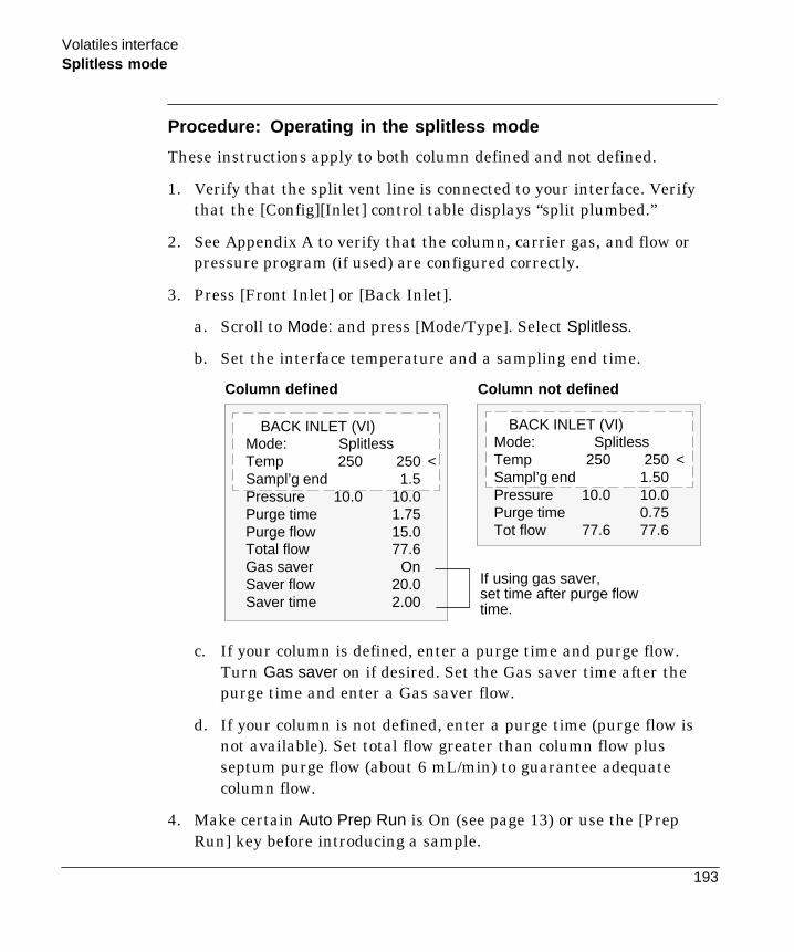
Volatiles interface
193
Splitless mode
Procedure: Operating in the splitless mode
These instructions apply to both column defined and not defined.
1. Verify that the split vent line is connected to your interface. Verifythat the [Config][Inlet] control table displays “split plumbed.”
2. See Appendix A to verify that the column, carrier gas, and flow orpressure program (if used) are configured correctly.
3. Press [Front Inlet] or [Back Inlet].
a. Scroll to Mode: and press [Mode/Type]. Select Splitless.
b. Set the interface temperature and a sampling end time.
BACK INLET (VI)Mode: SplitlessTemp 250 250 <Sampl’g end 1.50Pressure 10.0 10.0Purge time 0.75Tot flow 77.6 77.6
BACK INLET (VI)Mode: SplitlessTemp 250 250 <Sampl’g end 1.5Pressure 10.0 10.0Purge time 1.75Purge flow 15.0Total flow 77.6Gas saver OnSaver flow 20.0Saver time 2.00
If using gas saver,set time after purge flowtime.
Column not definedColumn defined
c. If your column is defined, enter a purge time and purge flow.Turn Gas saver on if desired. Set the Gas saver time after thepurge time and enter a Gas saver flow.
d. If your column is not defined, enter a purge time (purge flow isnot available). Set total flow greater than column flow plusseptum purge flow (about 6 mL/min) to guarantee adequatecolumn flow.
4. Make certain Auto Prep Run is On (see page 13) or use the [PrepRun] key before introducing a sample.
Volatiles Interface
194
Direct mode
Direct mode
Direct sample introduction permits a quantitative transfer of analytewithout risking contamination to the pneumatic system. It provides thesensitivity required for air toxics analyses. The interface’s minimal deadvolume also eliminates the potential interaction of solutes with poorlyswept, active surfaces.
To operate in the direct mode, you must physically disconnect the splitvent and reconfigure the GC. Instructions for performing theseprocedures are discussed later in this chapter.
Understanding the pneumatics
Before Pre Run, the interface is forward pressure controlled; pressure issensed downstream from the flow proportional valve. See Figure 31a.
During sampling, pressure upsets caused by switching valves in theexternal sampler can cause fluctuations in column flow rates. Tocompensate for this, the interface is flow controlled during samplingtime. The sampling flow rate is calculated from the pressure setpointthat is active when sample introduction begins. This flow control startswhen the GC goes into the Pre Run state (when your system isautomated and the Pre Run light is on or during manual operation whenyou press [Prep Run]) and ends after the interface’s Sampling endsetpoint expires.
Flow to the interface is measured by a flow sensor and controlled by aproportional valve. See Figure 31b.
After sampling end, the interface is forward pressure controlled; pressureis sensed downstream from the proportional valve. See Figure 31a.

Volatiles interface
195
Direct mode
Figure 31. Pneumatics for direct modea. Idle or after sampling end
b. Pre run to sampling end(sample introduction in progress)
To detector
FS SPR
PS
Gas phasesampler
Total flowcontrolloop
To detector
FS SPR
Gas phasesampler
Split linedisconnectedand plugged
Forwardpressure
control
FS
PS
SPRFlow sensor
Pressuresensor
Septum purgeregulator
Proportional valve
Frit block(pressure sensing line)
PS
Split line disconnectedand plugged
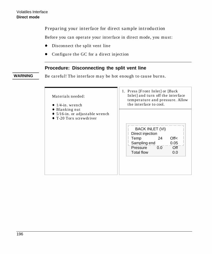
Volatiles Interface
196
Direct mode
Preparing your interface for direct sample introduction
Before you can operate your interface in direct mode, you must:
- Disconnect the split vent line
- Configure the GC for a direct injection
Procedure: Disconnecting the split vent line
Be careful! The interface may be hot enough to cause burns.
Materials needed:
- 1/4-in. wrench- Blanking nut- 5/16-in. or adjustable wrench- T-20 Torx screwdriver
1. Press [Front Inlet] or [BackInlet] and turn off the interfacetemperature and pressure. Allowthe interface to cool.
BACK INLET (VI)Direct injectionTemp 24 Off<Sampling end 0.05Pressure 0.0 OffTotal flow 0.0
WARNING

Volatiles interface
197
Direct mode
4. Loosen the the hex nut connecting thesplit vent line to the interface until youcan remove the line. Put the line aside.You do not need to plug it.
5. Install a blanking nut into the split lineport and finger tighten the nut. Tightenthe nut an additional 1/4 turn using twowrenches in opposition, the adjustablewrench on the interface and the 1/4-inwrench on the nut.
Splitvent
Blankingnut
2. If desired, remove the transfer line byloosening the hex nut with a 1/4-in.wrench. Remove the clamping plate fromthe interface by loosening the captivescrew with a T-20 Torx screwdriver. Putthe plate in a safe place.
Clampingplate
3. Carefully lift the interface out of theheater block.
Removethe
transferline
(optional)Interface
Pressuresensing
line
Transfer line

Volatiles Interface
198
Direct mode
6. Place the interface in the heaterblock. Replace the clamping plateyou removed in step no. 2 andtighten the screw until snug. Donot overtighten. If you removedthe transfer line, replace it.
Clampingplate
Restore the GC to normal operatingconditions. Perform a leak test onthe interface fittings.
Procedure: Configuring for a direct injection
The GC cannot sense the presence of the split vent. When you disconnector reconnect the vent, you must configure the GC so that the pneumaticswork properly.
1. Press [Config] [Back Inlet] or [Config] [Front Inlet].
2. Press [Mode/Type].
3. Choose Split removed.
4. Press [Back Inlet] or [Front Inlet]. If your GC is correctly configured,you will see the following display:
BACK INLET (VI)Direct injectionTemp 250 250 <Sampling end 0.05Pressure 10.0 10.0Total flow 0.0
If your interface is
configuredcorrectly, you willsee this display
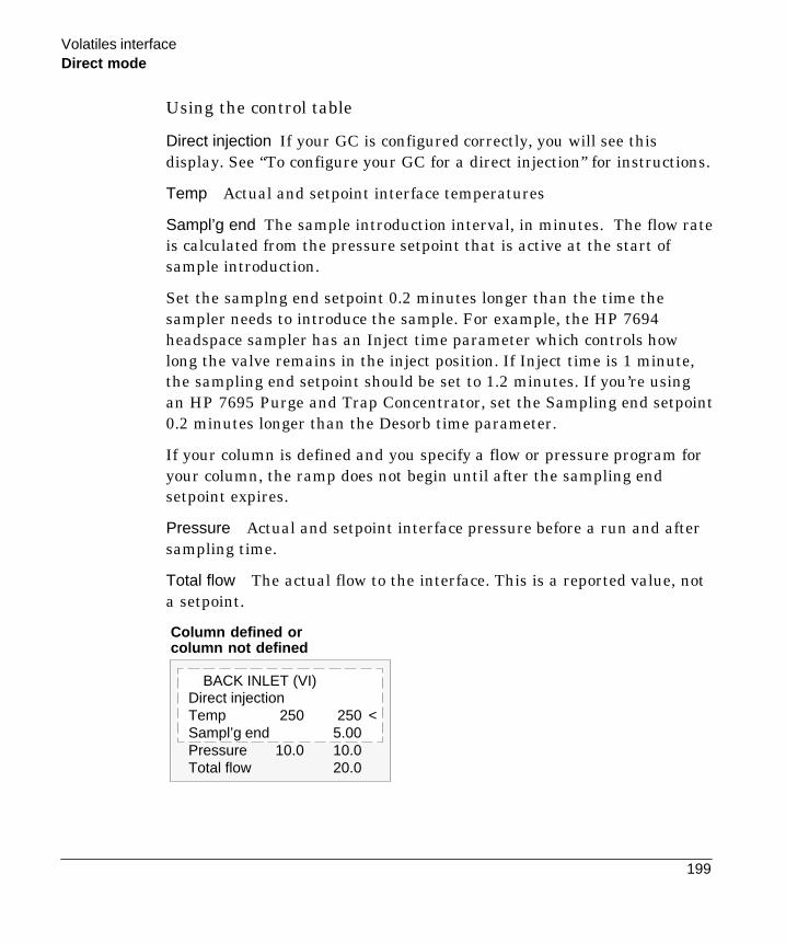
Volatiles interface
199
Direct mode
Using the control table
Direct injection If your GC is configured correctly, you will see thisdisplay. See “To configure your GC for a direct injection” for instructions.
Temp Actual and setpoint interface temperatures
Sampl’g end The sample introduction interval, in minutes. The flow rateis calculated from the pressure setpoint that is active at the start ofsample introduction.
Set the samplng end setpoint 0.2 minutes longer than the time thesampler needs to introduce the sample. For example, the HP 7694headspace sampler has an Inject time parameter which controls howlong the valve remains in the inject position. If Inject time is 1 minute,the sampling end setpoint should be set to 1.2 minutes. If you’re usingan HP 7695 Purge and Trap Concentrator, set the Sampling end setpoint0.2 minutes longer than the Desorb time parameter.
If your column is defined and you specify a flow or pressure program foryour column, the ramp does not begin until after the sampling endsetpoint expires.
Pressure Actual and setpoint interface pressure before a run and aftersampling time.
Total flow The actual flow to the interface. This is a reported value, nota setpoint.
BACK INLET (VI)Direct injectionTemp 250 250 <Sampl’g end 5.00Pressure 10.0 10.0Total flow 20.0
Column defined orcolumn not defined

Volatiles Interface
200
Direct mode
Some setpoints in the flow system are interdependent. If you change onesetpoint, other setpoints may change to compensate.
Table 27. Direct mode pneumatic setpoints
Column defined
When you change: These setpoints change:
Before and after sampling
Pressure Column flow*Total flow**
Column flow* PressureTotal flow**
During samplingYou cannot change pressure and flow setpoints duringsampling time.
Column not defined
Before and after samplingThe Column flow* setpoint is not available.You can change the pressure setpoint; other setpoints are notaffected.
During samplingYou cannot change pressure and flow setpoints duringsampling time.
*This setpoint appears on the column controltable.**This value is actual only.
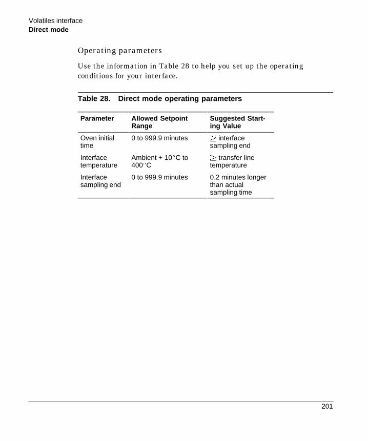
Volatiles interface
201
Direct mode
Operating parameters
Use the information in Table 28 to help you set up the operatingconditions for your interface.
Table 28. Direct mode operating parameters
Parameter Allowed SetpointRange
Suggested Start-ing Value
Oven initialtime
0 to 999.9 minutes | interfacesampling end
Interfacetemperature
Ambient + 10EC to400EC
| transfer linetemperature
Interfacesampling end
0 to 999.9 minutes 0.2 minutes longerthan actualsampling time

Volatiles Interface
202
Direct mode
Procedure: Operating in direct mode
These instructions apply to both column defined and not defined.
1. See Appendix A to verify that the column, carrier gas, and flow orpressure program (if used) are configured correctly.
2. Press [Front Inlet] or [Back Inlet].
a. Verify that your GC is configured for a direct injection.
b. Set the interface temperature.
c. Set sampling end. Set 0.2 minutes longer than the sampleintroduction time.
BACK INLET (VI)Direct injectionTemp 250 250 <Sampl’g end 0.05Pressure 10.0 10.0Total flow 0.0
3. Make certain Auto Prep Run is On (see page 13) or use the [PrepRun] key before introducing a sample.
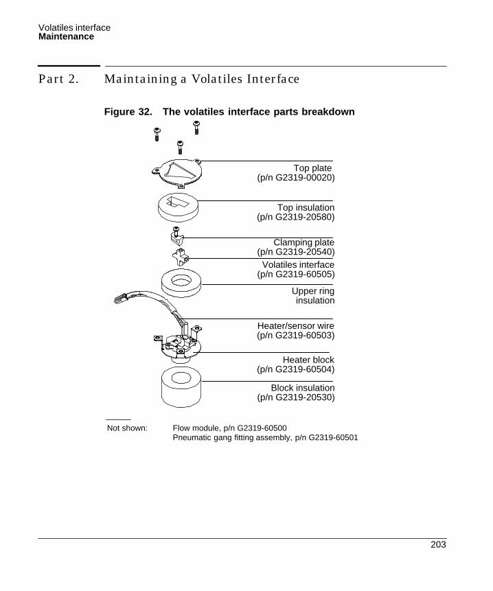
Volatiles interface
203
Maintenance
Part 2. Maintaining a Volatiles Interface
Figure 32. The volatiles interface parts breakdown
Clamping plate(p/n G2319-20540)Volatiles interface
(p/n G2319-60505)
Heater block(p/n G2319-60504)
Upper ringinsulation
Heater/sensor wire(p/n G2319-60503)
Top insulation(p/n G2319-20580)
Top plate(p/n G2319-00020)
Block insulation(p/n G2319-20530)
Not shown: Flow module, p/n G2319-60500Pneumatic gang fitting assembly, p/n G2319-60501

Volatiles Interface
204
Installing columns
Procedure: Installing columns
Wear safety glasses to protect your eyes from flying particles whilehandling, cutting, or installing columns. Use care in handling thesecolumns to prevent puncture wounds.
Be careful! The interface may be hot enough to cause burns.
Materials needed:
- Column nut- Ferrule- Column cutter- Magnifying loop- Isopropanol- Tissue- Typewriter correction fluid- 1/4-in. wrench- 5/16-in. or adjustable wrench- Metric ruler- T-20 Torx screwdriver
1. Press [Oven] and set the oven to35EC. Press [Front Inlet] or[Back Inlet] and turn off theinterface temperature andpressure. Allow the interface tocool. When the oventemperature reaches setpoint,turn the oven off.
WARNING
WARNING

Volatiles interface
205
Installing columns
3. Lift the interface out of the heater block.2. Disconnect the transfer line, if desired.Loosen the nut with a 1/4-in. wrenchand remove the line. Remove theclamping plate from the interface byloosening the captive screw with a T-20Torx screwdriver. Put the plate in a safeplace.
4. From inside the oven, push the columnthrough the opening in the oven top.
Pushcolumnthroughthisopening
Column
5. Grab the column from the oven top.
Column
Clampingplate
Remove thetransfer line
(optional) Interface
Heaterblock

Volatiles Interface
206
Installing columns
6. Place a capillary column nut and ferruleon the column and prepare the columnend. If you need help with this step, seeColumns and Traps in the GeneralInformation volume.
Column nut
Ferrule
Column
7. Position the column so it extends 6 mmabove the end of the ferrule. Mark thecolumn with typewriter correction fluidat a point even with the column nut.
2
0
22
cm
6 mm
Mark column here
8. Insert the prepared column in theinterface and finger tighten the columnnut.
9. Adjust the column position so that thecorrection fluid mark on the column iseven with the bottom of the columnnut.
Correctionfluid mark

Volatiles interface
207
Installing columns
10.Tighten the column nut an additional1/4 to 1/2 turn using two wrenches inopposition. Use the adjustable wrench tohold the interface while you tighten thecolumn nut with the 1/4-in. wrenchuntil the column cannot be pulled fromthe fitting with gentle pressure.
After the column is installed at both interface and detector, establish a flow of carrier gasthrough the interface. Heat the interface to operating temperature. Retighten the fittings,if necessary.
11.Replace the interface in the heater block.Replace the clamping plate and tightenthe screw until snug. If you removed thetransfer line, reinstall it.
Tighten1/4 turn
Clampingplate
Interface
Heaterblock

Volatiles Interface
208
Replacing or cleaning the interface
Procedure: Replacing or cleaning the interface
Materials needed:
- 1/4-in. or 7-mm wrench
- Sonicator or new interface
- T-20 Torx screwdriver
Preliminary Steps:
- If you have entered parameters that you do not want to lose, store them as a method.
- Allow the oven and interface to cool.
- Turn off all flows at the initial gas supply or set the flows to 0 in the inlet controltable.
1. Disconnect the transfer line. Loosen thenut with a 1/4-in. wrench and removethe line. Remove the clamping platefrom the interface by loosening thecaptive screw with a T-20 Torxscrewdriver. Put the plate in a safeplace.
Clampingplate
Interface
Heaterblock
2. Lift the interface out of the heater block.
Transferline

Volatiles interface
209
Replacing or cleaning the interface
5. Clean or replace the interface.If you are cleaning theinterface, sonicate it twice andthen rinse.
3. If a column is installed, removedit. See Columns and Traps in theGeneral Information volume ifyou need help with this step.
4. Remove the split and pressuresensing lines by loosening the hexnuts with the wrench.
Splitline
Sensingline
Removethecolumn
6. Reinstall the split line andpressure sensing lines andfinger tighten the hex nuts.Tighten the hex nuts anadditional 1/4 turn with thewrench.
Splitline
Sensingline

Volatiles Interface
210
Replacing or cleaning the interface
8. Place the interface in the heaterblock. Replace the clamping plateyou removed in step no. 1 andtighten the screw until snug. Donot overtighten.
7. Reinstall the column in theinterface. See Columns and Trapsin the General Informationvolume for instructions.
Interface
Reinstallthecolumn
Clampingplate
After the column is installed atboth interface and detector,establish a flow of carrier gasthrough the interface and maintainit for 10 to 15 minutes. Check forleaks. Heat the interface tooperating temperature andretighten the fittings, if necessary.
Transfer line
9. Reinstall the transfer line. Fingertighten the nut and then tightenan additional 1/4 turn with thewrench.
Volatiles interface
211
Leak checking the gas plumbing
Procedure: Leak testing the gas plumbing
Leaks in the gas plumbing can affect chromatographic resultsdramatically. The following procedure checks the flow system up to butnot including the interface flow module. If this portion of the systemproves to be leak-free, refer to the next procedure to check the interfaceand interface module.
Liquid leak detectors are not recommended, especially in areas wherecleanliness is very important. If you do use leak detection fluid,immediately rinse the fluid off to remove the soapy film.
To avoid a potential shock hazard when using liquid detection fluid, becareful not to spill leak solution on electrical leads, especially thedetector heater leads.
Materials needed:- Electronic leak detector capable of detecting your gas type or liquid
leak detection fluid. If you use leak detection fluid, wipe off excessfluid when you have completed the test.
- Two 7/16-in. wrenches
1. Using the leak detector, check each connection you have made forleaks.
2. Correct leaks by tightening the connections with the wrenches.Retest the connections; continue tightening until all connections areleak-free.
WARNING

Volatiles Interface
212
Leak checking the interface
Procedure: Leak testing the system
There are several places in the interface-sampler system that can leak.This procedure helps you determine, in general, if there is anunacceptable leak in the system. If there is a leak, you should use anelectronic leak detector to pinpoint the component that is leaking.
Be careful! The oven and interface may be hot enough to cause burns.
Materials needed:- No-hole ferrule
- 7/16-in. wrench
- 2, 1/8-in. SWAGELOK caps
- Gloves (if the interface is hot)
- 1/4-in. or 7 mm wrench
1. Complete the following preliminary steps:
a. If you have entered parameters that you do not want to lose,store them as a method.
b. Cool the oven to room temperature and then turn it off.
c. When the oven is cool, turn off the interface pressure from thekeyboard.
d. Remove the column, if one is installed, and plug the columnfitting with the column nut and a no-hole ferrule (see p. 33).
2. Cap the septum purge and split vent fittings located on the flowmodule with 1/8-in. Swagelock caps.
WARNING

Volatiles interface
213
Leak checking the interface
3. Enter a pressure setpoint between 20 and 25 psi, or enter yournormal operating pressure if it is greater. Make sure that thepressure at the initial gas supply is at least 10 psi higher than theinterface pressure. Wait a few minutes for the pressure toequilibrate.
Press [Frontinterface] or[Backinterface]
Mode: SplitTemp 150 150 <
BACK INLET (VI)Pressure 24.0 24.0Split ratio 25Split flow 0.0Tot flow 0.0 OffGas saver Off
Enter apressuresetpoint
4. Turn the pressure off from the inlet control table. Because theseptum purge, split vent, and column fittings are capped, gas shouldbe trapped in the system and the pressure should remain fairlyconstant. Turn the pressure off at the source if you want to isolatethe pneumatic system completely.
Because the pneumatics have been turned off, the alarm does not soundeven though there is no flow through the column.
Mode: SplitTemp 150 150 <
BACK INLET (VI)Pressure 24.0 OffSplit ratio 25Split flow 0.0Tot flow 0.0 OffGas saver Off
Press [Off]Monitorthe actualpressuredisplay

Volatiles Interface
214
Leak checking the interface
5. Continue to monitor pressure for 10 to 15 minutes. You can use theGC’s Stopwatch function. The pressure should drop approximately 1psi during the first 1 to 2 minutes. After an initial pressure drop ofabout 1 psi, the pressure should not drop more than 0.03 psi/min.
To accessstopwatch,press [Time]
9:56:08 12 Dec 94Last runtime 0.00Next runtime 999.99t=0:04.9 1/t=12.24
If the pressure drop is 0.03 psi/min or less, you can consider theinterface-gas sampler system leak-free.
If the pressure drops faster than the acceptable rate, you must checkthe interface and sampler systems separately to determine the sourceof the leak. See “Preparing the interface for a leak test” to create aclosed flow system, then return to this section and complete steps 3to 5 again.
If you find a leak in the interface, refer to “Correcting Leaks” in thischapter.
If the interface is leak-free, pressure check the sampling device. Seethe operating manual for your sampler for instructions.

Volatiles interface
215
Preparing the interface for a leak test
Procedure: Preparing the interface for a leak test
To leak check the interface independent of the gas sampling device, youmust disconnect the sampler from the interface to isolate the interfaceflow system from the sampler.
Be careful! The oven and interface may be hot enough to cause burns.
Materials needed:- 1/16-in. male GC nut and
- Graphite/vespel ferrule
1. Disconnect the transfer line from the interface (see p. 37, step 1).
2. Disconnect the carrier line from the sampler (see page 218 if youhave a Headspace sampler or page 221 if you have a Purge and TrapConcentrator.)
3. Prepare the end of the carrier line using the 1/16-in. male GC nutand the graphite/vespel ferrule.
4. Connect the carrier line to the interface where you removed thetransfer line and tighten the nut finger tight and then tighten 1/4 to1/2 turn with the 1/4-in. wrench.
5. Return to “Leak testing the system” in this chapter and repeat steps3 to 5.
WARNING

Volatiles Interface
216
Correcting leaks
Procedure: Correcting leaks
Materials needed:- Electronic leak detector
- Tool that will tighten leaking fittings — 1/4-in., 5/16-in., or 7-mmwrench
1. Use the electronic leak detector to check all areas of the interfacethat are potential sources of a leak. Potential leak areas are:
— The capped purge vent— The capped split vent— The plugged column connection— The area where the gas lines are plumbed to the interface
2. Correct leaks using the correct size wrench to tighten connections.You may need to repeat the leak test again to check for leaks.
If the pressure drop is now 0.03 psi/min or less, you can consider theinterface system leak-free.
If the pressure drops faster than this, continue to search for leaksand repeat the pressure test. If all fittings appear to be leak-free butthe interface system is still losing too much pressure, you may needto replace the interface module. Contact your Hewlett-Packardservice representative.
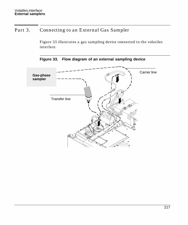
Volatiles interface
217
External samplers
Part 3. Connecting to an External Gas Sampler
Figure 33 illustrates a gas sampling device connected to the volatilesinterface.
Figure 33. Flow diagram of an external sampling device
Transfer line
Carrier lineGas-phasesampler

Volatiles Interface
218
Headspace sampler
Procedure: Connecting the HP 7694 headspace sampler
Materials needed:
- 1/16-in. to 1/8-in. reducer- 1/8-in. female Swagelok nut- 1/8-in. back ferrule- 1/8-in. front ferrule- Wrenches:
— One 7/16-in.— Two 5/16-in.— One 1/4-in.— One 7-mm
2. Remove the male fitting andVespel/graphite ferrule from thecarrier line. Keep the ferrule in asafe place.
1. Locate the GC’s carrier linetubing labeled “supply” attachedto the volatiles interface, andremove the carrier line from theinterface using a 1/4-in. wrench.
3. Get a 1/16-in. to 1/8-in. reducer,and remove the female nut andthe metal front and back ferrules.Keep the female nut in a safeplace.
Carrier line

Volatiles interface
219
Headspace sampler
4. Slide a 1/8-in. female Swagelok nut, a1/8-in. back ferrule, and a 1/8-in. frontferrule onto the unthreaded end of thereducer.
5. Connect the reducer to the gas supply portlabeled “Carrier” on the back of theheadspace sampler by tightening the1/8-in. female Swagelok nut using a7/16-in. wrench. Tighten the nut 1/4 turnpast finger tight.
7. Connect the carrier line to the gas supplyport by holding the reducer with one5/16-in. wrench while tightening the1/16-in. female Swagelok nut with another5/16-in. wrench. Tighten the fitting 1/4turn past finger tight. Do not overtighten.If the fitting leaks, tighten an additional1/8 turn until it seals.
6. Slide the 1/16-in. female nut from step 3and then the 1/16-in. Vespel/graphiteferrule from step 2 onto the end of thecarrier line.
Carrier gas in

Volatiles Interface
220
Headspace sampler
8. Locate the headspace sampler’stransfer line tubing.
9. Connect the transfer line (withthe preattached M5 nut and steelferrule) to the interface using a7-mm wrench. Tighten the M5nut 1/4 turn past finger tight. Donot overtighten. If the nut leaks,tighten an additional 1/8 turnuntil it seals.
Transferline
Transfer line
Nut Volatilesinterface
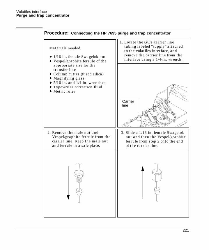
Volatiles interface
221
Purge and trap concentrator
Procedure: Connecting the HP 7695 purge and trap concentrator
Materials needed:
- 1/16-in. female Swagelok nut- Vespel/graphite ferrule of the
appropriate size for thetransfer line
- Column cutter (fused silica)- Magnifying glass- 5/16-in. and 1/4-in. wrenches- Typewriter correction fluid- Metric ruler
3. Slide a 1/16-in. female Swageloknut and then the Vespel/graphiteferrule from step 2 onto the endof the carrier line.
1. Locate the GC’s carrier linetubing labeled “supply” attachedto the volatiles interface, andremove the carrier line from theinterface using a 1/4-in. wrench.
2. Remove the male nut andVespel/graphite ferrule from thecarrier line. Keep the male nutand ferrule in a safe place.
Carrierline

Volatiles Interface
222
Purge and trap concentrator
4. Connect the carrier line to the gas supplyport labeled “Carrier Gas” on the back ofthe P&T concentrator using a 5/16-in.wrench. Tighten the nut 1/4 turn pastfinger tight. Do not overtighten. If the nutleaks, tighten an additional 1/8 turn untilit seals.
5. Locate the P&T concentrator’s transferline tubing.
6. Slide the 1/16-in. male nut from step 2and then an appropriate Vespel/graphiteferrule onto the end of the transfer line.
7. If you are using a nickel-plated transferline, proceed to step 8.If you are using a fused-silica transferline, prepare the end of the fused silicaline. See “Columns and Traps” in theGeneral Information volume if you needhelp with this step.
Carrier Gas
Transfer line
Nut
Ferrule (size dependson the transfer line
you’re using)

Volatiles interface
223
Purge and trap concentrator
8. Position the transfer line so that 2 mm of tubing is exposed in front of the ferrule, andmark the transfer line with typewriter correction fluid at a point even with the nut.
7. Connect the transfer line to the volatiles interface by finger tightening the 1/16-in. malenut while adjusting the transfer line’s position so that the correction fluid mark staysaligned with the nut. Using a 1/4-in. wrench, tighten the nut 1/4 turn past finger tight.Do not overtighten. If the fitting leaks, tighten an additional 1/8 turn until it seals.
20 22cm
2 mm
Mark transfer linehere
Nut
Transfer line
Volatiles interface

7
NonEPC Inlets
Purged packed inlet, 226Split/splitless inlet—split mode, 226Split/splitless inlet—splitless mode, 226Procedure: Configuring a nonEPC inlet, 227Inlet control tables, 228Column control tables, 229Procedure: Setting carrier flow for the purged packed inlet, 230Procedure: Setting flows for the split mode inlet, 231Procedure: Setting flows for the splitless mode, 233

226
Chapter 7.NonEPC Inlets
Controls for these inlets are located on a pneumatics module attached tothe left side of the GC.
Purged packed inlet
The only adjustment for this inlet is the carrier gas flow through thecolumn. Septum purge flow is set automatically based on the source gaspressure. It can be measured at a vent on the front panel.
Split/splitless inlet—split mode
The carrier gas divides between the column and the split vent dependingon their relative flow resistances. A small amount of carrier gas sweepsthe lower side of the septum and exits through the septum purge controland vent.
Split/splitless inlet—splitless mode
In a splitless injection, a valve is actuated by [Prep Run] that preventscarrier gas from exiting the bottom of the inlet liner. Total flow does notchange, but most of it exits through the septum purge line. All carriergas that passes through the liner goes to the column—the sample is notsplit.
At purge time, the valve switches to sweep out residual vapor in theinlet. The system is now in the split configuration, with the purge flowand residual vapor—mostly solvent—exiting through the split vent.

227
NonEPC inlets
Configuration
The GC is aware that a nonEPC inlet is present—it looks for theheater/sensor connections—but does not know what kind. You mustsupply this information through configuration.
Procedure: Configuring a nonEPC inlet
1. Press [Config], select Instrument., and [Enter].
CONFIG INSTRUMENTSerial# US00100001Auto prep run OffF inlet type: S/SL <B inlet type: S/SL
2. Select the inlet and press [Mode/Type].
FRONT INLET TYPEPurged packed
*Split/splitlessCool on-column <UnknownNone
3. Select a type and [Enter].
4. Press [Config][Front Inlet] (or [Back Inlet]).
CONFIG FRONT INLETGas type He <
5. Press [Mode/Type], select a gas, and [Enter].

228
NonEPC inlets
Inlet control tables
The inlet control tables for nonEPC inlets are similar to those for theEPC versions except that flow and pressure settings are absent. SeeFigure 34.
Figure 34. NonEPC inlet control tables
FRONT INLET (He)Mode: Split <Temp 150 150
FRONT INLET (He)Mode: Splitless <Temp 150 150Purge time 2.00
FRONT INLET (He)Temp 150 150 <
Split/splitless inlet in split mode
Split/splitless inlet in splitless mode
Purged packed inlet

229
NonEPC inlets
Column control tables
When a nonEPC split/splitless inlet is used with a defined column, thecolumn control table becomes a calculator. Although you cannot controlflows from the keyboard, you can determine the flows to be set manually.
Column 1 (He)Dim 30.0 m 320 uPressure 0.0Calc flow 0.0Calc velocity 0
Enter a pressure. Flow and averagelinear velocity are calculated and dis-played.

230
NonEPC inlets
Procedure: Setting carrier flow for the purged packed inlet
The internal flow path in the instrument is:
INCRCARRIER FLOW
PACKED
COLUMNHEAD PRESSURE
Column DetectorIN OUTInlet
PURGED
SEPTUM PURGE
VENT
1. Locate the knob labeled CARRIER FLOW. Turn it clockwise as far asit will go. Do not force the knob; when it closes it comes to a slightly“soft” stop.
2. Open the carrier gas cylinder valve and set the delivery pressure ofthe two-stage regulator to 410 kPa (60 psi). If there is a localregulator in the carrier gas line, set the cylinder regulator to 550 kPa(80 psi) and the local regulator to 410 kPa (60 psi).
3. Attach a flow meter to the detector outlet. There should be no flow atthis time. If there is, turn the detector gas flows off from thekeyboard.
4. Turn the CARRIER FLOW knob in the INCR direction to turn thecarrier gas on. Adjust and measure to achieve the desired flow. Ifnecessary, increase the source pressure.
The septum purge is set automatically.

231
NonEPC inlets
Procedure: Setting flows for the split mode inlet
The internal flow path in the instrument is:
SPLIT
SPLIT VENT PURGE VENT
INCRTOTAL FLOW SEPTUM PURGE
INCR
COLUMNHEAD PRES-SURE
INCR
IN Column Detector OUTInlet
Split mode
1. Locate the knob labeled TOTAL FLOW. Turn it clockwise as far as itwill go. Do not force the knob; when it closes it comes to a slightly“soft” stop.
2. Locate the knob marked SEPTUM PURGE. Turn it counterclockwiseto turn the flow off. There is no definite stop position; when the knobturns freely (does not seem to be touching anything inside), it is off.
3. Open the carrier gas cylinder valve and set the delivery pressure ofthe two-stage regulator to 410 kPa (60 psi). If there is a localregulator in the carrier gas line, set the cylinder regulator to 550 kPa(80 psi) and the local regulator to 410 kPa (60 psi). If you are usingsmall-bore capillary columns, you may have to use higher pressures.
4. Attach a flow meter to the detector outlet. There should be no flow atthis time. If there is, turn the detector gas controls off from thekeyboard.

232
NonEPC inlets
5. Turn the TOTAL FLOW knob in the INCR direction to turn thecarrier gas flow on.
6. Turn the COLUMN HEAD PRESSURE knob in the INCR direction.Adjust and measure to achieve the desired column flow. If youcannot, increase TOTAL FLOW until you can. Use TOTAL FLOW forcoarse and COLUMN HEAD PRESSURE for fine adjustment.
7. Move the flow meter to the SPLIT VENT. Measure and adjust TOTALFLOW to achieve the desired split flow. If necessary, increase thesource pressure.
8. Move the flow meter to the PURGE VENT. Turn the SEPTUM PURGEknob in the INCR direction to achieve the desired septum purgeflow.
9. Repeat steps 6, 7, and 8 until all flows are correct.

233
NonEPC inlets
Procedure: Setting flows for the splitless mode
The internal flow paths in the instrument are:
SPLIT
SPLIT VENT PURGE VENT
INCRTOTAL FLOW SEPTUM PURGE
INCR
COLUMNHEAD PRES-SURE
INCR
IN Column Detector OUTInlet
Splitless mode betweenPrep Run and purge time(ready for injection)
SPLIT
SPLIT VENT PURGE VENT
INCRTOTAL FLOW SEPTUM PURGE
INCR
COLUMNHEAD PRES-SURE
INCR
IN Column Detector OUTInlet
Splitless mode after purge time(state for setting flows)

234
NonEPC inlets
1. Locate the knob labeled TOTAL FLOW. Turn it clockwise as far as itwill go. Do not force the knob; when it closes it comes to a slightly“soft” stop.
2. Locate the knob marked SEPTUM PURGE. Turn it counterclockwiseto turn the flow off. There is no definite stop position; when the knobturns freely (does not seem to be touching anything inside), it is off.
3. Open the carrier gas cylinder valve and set the delivery pressure ofthe two-stage regulator to 410 kPa (60 psi). If there is a localregulator in the carrier gas line, set the cylinder regulator to 550 kPa(80 psi) and the local regulator to 410 kPa (60 psi). If you are usingsmall-bore capillary columns, you may have to use higher pressures.
4. Attach a flow meter to the detector outlet. There should be no flow atthis time. If there is, turn the detector gas controls off from thekeyboard.
5. Turn the TOTAL FLOW knob in the INCR direction to turn thecarrier gas flow on.
6. Turn the COLUMN HEAD PRESSURE knob in the INCR direction.Adjust and measure to achieve the desired column flow. If youcannot, increase TOTAL FLOW until you can. Use TOTAL FLOW forcoarse and COLUMN HEAD PRESSURE for fine adjustment.
7. Move the flow meter to the SPLIT/SPLITLESS INLET VENT. Measureand adjust TOTAL FLOW to achieve the desired split flow. Ifnecessary, increase the source pressure.
8. Move the flow meter to the SEPTUM PURGE VENT. Turn theSEPTUM PURGE knob in the INCR direction to achieve the desiredseptum purge flow.
9. Repeat steps 6, 7, and 8 until all flows are correct.

Appendix A
Configuration Information
Preparing for analysis, 236To configure the carrier gas, 237To select a column mode, 238To set the initial flow or pressure or average linear velocity, 239To enter a pressure or flow program, 240

���
Appendix A:Configuration Information
Preparing for analysis
All operating procedures begin with the four steps below. Note that thereare two variations of step 2, one for column defined and one for columnnot defined.
The rest of the material in this appendix provides the details of thesesteps. It is copied from the General Information volume and printed hereas a convenience to eliminate jumping back and forth between the twobooks.
1.. Verify that a column is installed and the correct liner is in the inlet.
2.. Configure the column. Press [Config][Col 1] or [Config][Col 2].
a. To define the column, enter the dimensions requested.
or
b. To leave the column not defined, enter 0 for either column lengthor column diameter.
3.. Press [Col 1] or [Col 2]. Verify that the gas type in the title line iscorrect. Change if necessary.
4.. Specify a column flow or pressure mode and a starting flow orpressure. Enter a flow or pressure program, if desired.

237
To configure the carrier gas
1.. Press [Config] [Front Inlet] or [Config] [Back Inlet].
2.. Press [Mode/Type] to see the carrier gas menu.
Carrier gas type.Press [Mode/Type] to getmenu.
Gas type He <CONFIG FRONT INLET
*HeliumHydrogen <NitrogenArgon methane 5%
FRONT INLET GAS
3.. Scroll to the gas you will use. Press [Enter].
This completes carrier gas configuration. See the Inlets volume for moredetail.
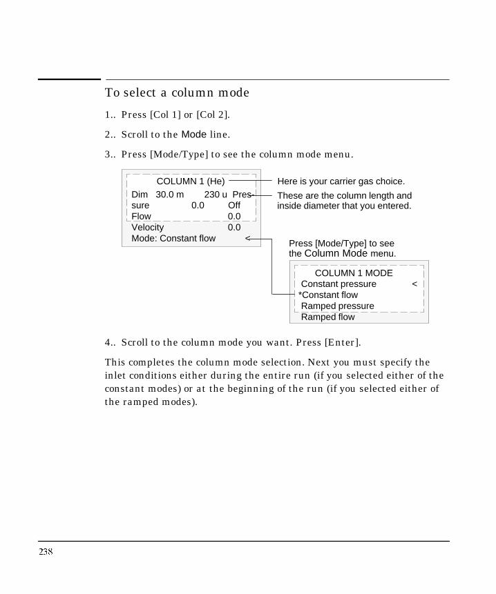
���
To select a column mode
1.. Press [Col 1] or [Col 2].
2.. Scroll to the Mode line.
3.. Press [Mode/Type] to see the column mode menu.
Dim 30.0 m 230 u Pres-sure 0.0 OffFlow 0.0Velocity 0.0Mode: Constant flow <
COLUMN 1 (He)
COLUMN 1 MODEConstant pressure <
*Constant flowRamped pressureRamped flow
Press [Mode/Type] to seethe Column Mode menu.
These are the column length andinside diameter that you entered.
Here is your carrier gas choice.
4.. Scroll to the column mode you want. Press [Enter].
This completes the column mode selection. Next you must specify theinlet conditions either during the entire run (if you selected either of theconstant modes) or at the beginning of the run (if you selected either ofthe ramped modes).

239
To set the initial flow or pressure or average linearvelocity
1.. Press [Col 1] or [Col 2].
The control table will have one of these, depending on the columnmode selected:
Mode: Ramped flow <Init flow 4.0Init time 2.0Rate 1 0.5Final flow 18.0Final time 12.0Rate 2 (Off) 0.00
Mode: Const flow <
Mode: Const pressure <
Mode: Ramped pressure <Init pressure 10.0Init time 1.0Rate 1 1.0Final pressure125.0Final time 15.0Rate 2 (Off) 0.00
COLUMN 1Dim 50.0 m230 u Pressure2.5 2.5Flow 10.0Velocity 74Mode: Constant flow <
The column length and inside diameter.
The column mode; see below.
You set one of these. The GCcalculates the other two.
2.. Scroll to the Pressure or Flow or Velocity line.
3.. Type the desired initial value, followed by [Enter]. The GC computes anddisplays the other two values. Adjust them, if you choose to, by repeatingsteps 2 and 3. Note that changing any one changes all three.
This completes setting the initial carrier gas condition.

���
To enter a pressure or flow program
1.. Press [Col 1] or [Col 2].
COLUMN 1Dim 50.0 m 250 uPressure 10.0 10.0Flow 0.0Velocity 0.0Mode: Ramped presInit Pres 10.0Init time 1.5Rate 1 0.5Final pres 1 20.0Final time 1 2.5Rate 2 (Off) 0.00
Because Mode is Rampedpres, the ramp is given inpressure units.
Pressure (in this example) isthe controlled setpoint; theothers are reported values.
2.. Scroll to Init Pres (or Init flow). Type the desired value and press[Enter].
3.. Similarly, enter a value for Init time. This completes the initial(constant pressure) part of the program.
4.. To begin a ramp, enter a positive value for Rate 1. It does not matterwhether you are programming up or down—the rate is alwayspositive.
5.. If Rate 1 is zero, the program ends here. If you enter any other value,the Final value lines for the first ramp appear and the cursor movesto the line.
6.. Enter values for Final pres 1 (or Final flow 1) and Final time 1. Thiscompletes the first ramp.
7.. To enter a second (or third) ramp, scroll to the appropriate Rate lineand repeat steps 5 and 6.

AAdapter, PTV inlet, replacing, 161
Auto Prep Run, 14
CCarrier gas, flow rate and column size, 4
Cleaningcool oncolumn inlet, 106PTV inlet, septumless head, 165purged packed inlet, 81split/splitless inlet, 54Volatiles Interface, 208
Columncontrol table, 7mode selection, 238PTV inlet, installation, 162Volatiles interface, installation, 204
Configurationcarrier gas, 237nonEPC inlet, 227PTV inlet, 120Volatiles Interface, direct mode, 198
Control tablecolumn, 7column undefined, purged packed inlet, 65nonEPC inlet, 228, 229packed column, 9PTV inlet
pulsed split mode, 129pulsed splitless mode, 140solvent vent mode, 149split mode, 125splitless mode, 136
purged packed inlet, 65split/splitless inlet
pulsed split mode, 31pulsed splitless mode, 33split mode, 22splitless mode, 26
undefined column, 9Volatiles Interface
direct mode, 199lit d 182
cleaning, 106cooling tower, 88, 105, 107
manual injection, 93correcting leaks, 113CryoBlast, 94cryogenic considerations, 95duckbill septum, 88fused silica needle, 101, 102hardware, 85hardware problems, 100injection with septum nut, 87inserts, 87installing insert, 90leak testing, 110
gas plumbing, 109maintenance, 98manual injection, septum nut, 92needles, 87operation, 97septum changing, 103septum nut, 89, 105, 107setpoint ranges, 95temperature programming, 95, 96track oven mode, 94
Cooling tower, cool oncolumn inlet, 88, 105,107
Cryo shutdown, PTV inlet, 122
CryoBlast, cool oncolumn inlet, 94
DDirect mode, Volatiles Interface, 194, 202
control table, 199parameters, 201
FFerrule, Teflon, replacing, 167
Flowinitial, 239program, 240PTV inlet, solvent vent mode, 145
GGas, carrier, configuration, 237
Gas sa er 11

Headspace sampler, Volatiles Interface, con-nection, 218
Hydrogen, 2
IInitial flow, 239
Initial linear velocity, 239
Initial pressure, 239
Injector configuration, large volume injection,154
Injector parameters, large volume injection,155
InletnonEPC, configuration, 227split/splitless, septum, 18
Inlets, overview, 3
Insertscool oncolumn inlet, 87purged packed inlet, 59, 63
Installing columnsPTV inlet, 162Volatiles Interface, 204
LLarge volume injection
ChemStation requirements, 154example, 156GC requirements, 153sampler requirements, 153
Leak correctioncool oncolumn inlet, 113purged packed inlet, 80split/splitless inlet, 53Volatiles Interface, 216
Leak testingcool oncolumn inlet, 110
gas plumbing, 109purged packed inlet
EPC, 75gas plumbing, 74
Volatiles Interface, 212gas plumbing, 211preparation, 215
LinersPTV inlet, 171
replacing, 172purged packed inlet, 59, 61split/splitless inlet, 19
MMaintenance
cool oncolumn inlet, 98PTV inlet, 161purged packed inlet, 67split/splitless inlet, 35Volatiles Interface, 203
Manual injection, cool oncolumn inletcooling tower, 93septum nut, 92
Merlin microseal, 170
NNeedle size, cool oncolumn inlet, 91
Needles, fused silica, cool oncolumn inlet, 101,102
OOring changing
purged packed inlet, 72split/splitless inlet, 39, 41
PPrep Run, 11, 13
Auto, 14key, 13
Pressureinitial, 239program, 240select units, 5solvent vent mode, 145
i i

Changing septum, 89, 104Changing septum nut, 89Checking needle/column size, 91Cleaning inlet, 106Correcting leaks, 113Installing fused silica needle, 102Installing inserts, 90Leak testing gas plumbing, 109Leak testing inlet, 110Manual injection with cooling tower, 93Manual injection with septum nut, 92Operating, 97Programming temperature, 96Replacing fused silica needle, 101
Gas saver, 12NonEPC inlets, Configuration, 227NonEPC purged packed, Setting carrier flow,
230NonEPC split/splitless
Setting split mode flows, 231Setting splitless mode flows, 233
Pressure units, Select psi, kPa, bar, 5PTV
Changing septum, 170Cleaning septumless head, 165Installing columns, 162Pulsed split mode, column defined, 130Pulsed split mode, column not defined, 131Pulsed splitless mode, column defined, 141Pulsed splitless mode, column not defined,
142Removing septum head, 169Removing septumless head, 164Replacing inlet adapters, 161Replacing liners, 172Replacing Teflon ferrule, 167Solvent vent mode, column defined, 151Solvent vent mode, column not defined, 152Split mode, column defined, 126Split mode, column not defined, 127Splitless mode, column defined, 138Splitless mode, column not defined, 139
Purged packedChanging Oring, 72Changing septum, 68Cleaning inlet, 81Correcting leaks, 80Installing glass inserts, 63Installing liners, 61
Using undefined capillary columns, 66Split/splitless
Changing liners, 19Changing Oring, 41Changing septum, 37Cleaning inlet, 54Correcting leaks, 53Leak testing EPC inlet, 47Leak testing gas plumbing, 46Leak testing nonEPC inlet, 51Pulsed split mode, 32Pulsed splitless mode, 34Replacing base seal, 44Split mode, column defined, 23Split mode, column not defined, 24Splitless mode, column defined, 28Splitless mode, column not defined, 29
Volatiles interfaceConfiguring for direct injection, 198Connecting headspace sampler, 218Connecting purge and trap concentrator,
221Correcting leaks, 216Direct mode, 202Disconnecting split vent line, 196Installing columns, 204Leak testing gas plumbing, 211Leak testing system, 212Preparing for leak test, 215Replacing or cleaning interface, 208Split mode, column defined, 185Split mode, column not defined, 186Splitless mode, 193
Programmingcolumn flow, 240cool oncolumn inlet temperature, 95inlet pressure, 240
PTV inlet, 116, 161changing septum, 170configuration, 120cooling, 120cryo shutdown, 122heating, 119installing columns, 162large volume injection
ChemStation requirements, 154example, 156GC requirements, 153injector configuration, 154

pulsed split modecolumn defined, 130column undefined, 131control table, 129
pulsed splitless modecolumn defined, 141column undefined, 142control table, 140
replaceable parts, 174replacing adapters, 161replacing liners, 172sampling heads, 118septum head, 168
removing, 169septumless head
cleaning, 165removing, 164
solvent vent mode, 143column defined, 151column undefined, 152control table, 149large volume injection, 153order of operations, 146Start Run, 148temperature, pressure and flow, 145timelines, 147
split mode, 123column defined, 126column undefined, 127control table, 125
split modes, temperatures, 124splitless mode, 132
column defined, 138column undefined, 139control table, 136starting values, 137
system components, 117system requirements, 116Teflon ferrule, replacing, 167temperature, 135
Pulsed modes, PTV inlet, 128
Pulsed split mode, PTV inletcolumn defined, 130column undefined, 131
Pulsed splitless mode, PTV inletcolumn defined, 141column undefined, 142control table 140
changing Oring, 72changing septum, 68cleaning, 81column defined, 66column undefined, 66control table, column defined, 65correcting leaks, 80inserts, 59installing inserts, 63installing liners, 61leak testing
EPC, 75gas plumbing, 74nonEPC, 78
liners, 59maintenance, 67nonEPC, 230packed column, control table, 65packed columns, 66
RRetention gap, 94
SSampler connection, Volatiles Interface, 217
Sampling heads, PTV inlet, 118
Septum changingcool oncolumn inlet, 89, 103, 104PTV inlet, 170purged packed inlet, 68split/splitless inlet, 36, 37
Septum head, PTV inlet, 168removing, 169
Septum nut, cool oncolumn inlet, 87, 105, 107changing, 89
Septum purge, 15
Septum tightening, 18
Septumless head, PTV inletcleaning, 165removing, 164
Setpoints, cool oncolumn inlet, 95
Shutdown, cryo, 122

PTV inletcolumn defined, 151column undefined, 152control table, 149large volume injection, 153
Split modePTV inlet, 123
column defined, 126column undefined, 127
split/splitless inlet, 21column defined, 23column undefined, 24
Volatiles Interface, 180column defined, 185column undefined, 186parameters, 184
Split vent line, Volatiles Interface, disconnect,196
Split/splitless inlet, 18changing Oring, 39, 41changing septum, 36, 37cleaning, 54correcting leaks, 53leak testing, 46
EPC, 47nonEPC, 51
liners, 19maintenance, 35nonEPC, 229pressure, 18pulsed modes, 30pulsed split mode, 32
control table, 31pulsed splitless mode, 34
control table, 33replacing base seal, 43, 44septum tightening, 18split mode, 21
control table, 22nonEPC, 231
splitless mode, 25column defined, 28column undefined, 29control table, 26nonEPC, 233parameters, 27
Splitless modePTV inlet, 132
column undefined, 29Volatiles Interface, 187, 193
parameters, 192
Start Run, PTV inlet, solvent vent mode, 148
TTeflon ferrule, PTV inlet, replacing, 167
Temperature, PTV inlet, 135solvent vent mode, 145split modes, 124
Temperature programming, cool oncolumninlet, 95, 96
Timelines, PTV inlet, solvent vent mode, 147
Track oven mode, cool oncolumn inlet, 94
UUsing hydrogen, 2
VVolatiles Interface, 178
cleaning or replacing, 208connection to sampler, 217correcting leaks, 216direct mode, 194, 202
configuration, 198control table, 199disconnect split vent line, 196parameters, 201
installing columns, 204leak testing, 212
gas plumbing, 211preparation, 215
maintenance, 203overview, 179split mode, 180
column defined, 185column undefined, 186control table, 182parameters, 184
split vent line, disconnecting, 196

Manual Part No. G1530-90450H l P k d C
This product is recyclable.
Printed on recycled paper.