hp ip distance gateway user guide - apache welcome pageh20628.€¦ · · 2017-10-13commands ......
TRANSCRIPT

HP IP Distance Gateway User Guide
AbstractThis guide provides information about installing, configuring, restoring, and managing the HP IP Distance Gateway (mpx110).It is intended for system administrators responsible for installing, managing, and servicing the mpx110 and the SAN to whichit is attached.
HP Part Number: 5697-2060Published: June 2012Edition: 9

© Copyright 2008, 2012 Hewlett-Packard Development Company, L.P.
The information contained herein is subject to change without notice. The only warranties for HP products and services are set forth in the expresswarranty statements accompanying such products and services. Nothing herein should be construed as constituting an additional warranty. HP shallnot be liable for technical or editorial errors or omissions contained herein.
Microsoft and Windows are U.S. registered trademarks of Microsoft Corporation.
Java is a U.S. trademark of Sun Microsystems, Inc.
Contents1 Overview..................................................................................................8
mpx110 product description.......................................................................................................8Optional equipment..................................................................................................................8FCIP overview..........................................................................................................................9Using FCIP to encapsulate FC packets.........................................................................................9Redundant FCIP network structure example.................................................................................10
2 Configuration rules and guidelines..............................................................11Supported configurations.........................................................................................................11HP Continuous Access P6000/EVA 3-site configurations..............................................................17
3-site configuration with four mpx110 gateways......................................................................173-site configuration with six mpx110 gateways.......................................................................173-site configuration with eight mpx110 gateways....................................................................193-site configuration with six gateways and full inter-site connectivity..........................................20
Configuration rules and guidelines............................................................................................21General configuration rules.................................................................................................21Operating system and multipath support...............................................................................21P6000/EVA storage system rules and guidelines....................................................................21
P6000/EVA storage system software...............................................................................22P9000/XP storage system rules and guidelines......................................................................22
P9000/XP storage system software..................................................................................22Fibre Channel switch and firmware support...........................................................................22
FC switch requirements..................................................................................................22IP network requirements......................................................................................................23
IP performance tuning.............................................................................................................25Distance...........................................................................................................................25Bandwidth per route...........................................................................................................25Latency.............................................................................................................................25MTU/Jumbo frames............................................................................................................25Compression.....................................................................................................................26TCP window size/scaling performance tuning........................................................................26
Modifying the window size and scaling factor..................................................................26TCP window size recommendations.................................................................................28
3 Installation and upgrades..........................................................................33Verifying mpx110 requirements ................................................................................................33Pre-installation checklist...........................................................................................................34Rack mounting the mpx110......................................................................................................34Installing the SFPs...................................................................................................................35Management.........................................................................................................................35
Installing the management application..................................................................................36HP mpx Manager for Windows...........................................................................................37HP mpx Manager for Linux .................................................................................................37Setting mpx110 management port parameters........................................................................37
Configuring Fibre Channel switch settings for the mpx110.............................................................39B-series Fibre Channel switch parameters..............................................................................39C-series Fibre Channel switch parameters..............................................................................40H-series Fibre Channel switch parameters..............................................................................40
Configuring the mpx110 for connecting remote SANs..................................................................40Configuring FCIP routes...........................................................................................................41Cabling the mpx110 Fibre Channel, GE, and management ports...................................................44Verifying FCIP links and firmware version...................................................................................44
Contents 3
Firmware upgrades.................................................................................................................44Using the mpx Manager GUI to upgrade firmware.................................................................44Using the CLI to upgrade firmware.......................................................................................44Recovery process...............................................................................................................46
Removal and replacement........................................................................................................46Removing an mpx110.........................................................................................................46Replacing an mpx110.........................................................................................................46
Services................................................................................................................................47Security.................................................................................................................................47Diagnostics and troubleshooting...............................................................................................48
POST diagnostics...............................................................................................................48Heartbeat LED (green)........................................................................................................48Input Power LED (green)......................................................................................................49System Fault LED (amber)....................................................................................................49Fibre Channel Port LEDs......................................................................................................49
4 Using the HP mpx Manager utility..............................................................50Overview..............................................................................................................................50
Menu bar.........................................................................................................................52File menu..........................................................................................................................52View menu........................................................................................................................52Settings menu....................................................................................................................53Wizards menu...................................................................................................................53Help menu........................................................................................................................54Tool bar...........................................................................................................................54Action menu......................................................................................................................54System tree window...........................................................................................................56mpx110 gateway...............................................................................................................58
Information tab.............................................................................................................58Security tab..................................................................................................................62SNMP Management tab................................................................................................63
FCIP routes........................................................................................................................64FCIP Route Info tab settings.............................................................................................64
Starting the mpx110 Manager GUI...........................................................................................67Using wizards........................................................................................................................68
Firmware Update Wizard....................................................................................................69FCIP Route Add Wizard......................................................................................................71FCIP Route Remove............................................................................................................75
5 Support and other resources......................................................................77Related documentation............................................................................................................77Conventions...........................................................................................................................77
Document conventions and symbols......................................................................................77HP technical support...............................................................................................................78Subscription service................................................................................................................78Other HP websites..................................................................................................................78
A Command-line interface............................................................................80Logging on to the mpx110........................................................................................................80User accounts........................................................................................................................80Working with SAN mpx110 configurations.................................................................................80
Modifying a configuration...................................................................................................80Saving and restoring mpx110 configurations..........................................................................80Saving mpx110 configuration and persistence........................................................................80Restoring mpx110 configuration and persistence.....................................................................82
Commands............................................................................................................................83
4 Contents

Admin command...............................................................................................................84Beacon command..............................................................................................................85Clear command.................................................................................................................85Date command..................................................................................................................85FcipRoute command...........................................................................................................85FRU command...................................................................................................................88Help command..................................................................................................................89History command...............................................................................................................90Image command................................................................................................................91Logout command...............................................................................................................91Password command...........................................................................................................91Ping command..................................................................................................................92Quit command..................................................................................................................92Reboot command...............................................................................................................92Reset factory command.......................................................................................................93Save command..................................................................................................................94Set command....................................................................................................................94Set FC command...............................................................................................................95Set MGMT command.........................................................................................................96Set NTP command.............................................................................................................97Set Properties command.....................................................................................................97Set SNMP command..........................................................................................................98Set System command..........................................................................................................98Show command...............................................................................................................100Show FcipRoutes command...............................................................................................101Show Logs command.......................................................................................................102Show Memory command..................................................................................................102Show MGMT command....................................................................................................103Show NTP command........................................................................................................103Show Performance command............................................................................................104Show Properties command................................................................................................104Show SNMP command.....................................................................................................105Show Stats command.......................................................................................................106Show System command....................................................................................................109Show Targets command....................................................................................................110Show VLAN command.....................................................................................................111Shutdown command.........................................................................................................111Target command..............................................................................................................111Traceroute command........................................................................................................112
B Log data...............................................................................................113Informational log messages....................................................................................................113
Application modules........................................................................................................113iSCSI driver.....................................................................................................................114Fibre Channel driver.........................................................................................................116User modules..................................................................................................................117FCIP...............................................................................................................................118TOE driver......................................................................................................................119System............................................................................................................................119
Error log messages...............................................................................................................119Application modules........................................................................................................119iSCSI driver.....................................................................................................................124Fibre Channel driver.........................................................................................................125Error log messages in user modules....................................................................................127System............................................................................................................................128
Contents 5
Fatal log messages...............................................................................................................128iSCSI driver.....................................................................................................................128Fibre Channel driver.........................................................................................................130TOE driver......................................................................................................................131System............................................................................................................................131
C Simple Network Management Protocol.....................................................132SNMP properties..................................................................................................................132SNMP trap configuration.......................................................................................................132Management Information Base ..............................................................................................132
System information...........................................................................................................133qsrSerialNumber.........................................................................................................133qsrHwVersion.............................................................................................................133qsrSwVersion..............................................................................................................133qsrNoOfFcPorts..........................................................................................................133qsrNoOfGbEPorts.......................................................................................................133qsrAgentVersion..........................................................................................................133
Network port table...........................................................................................................133qsrNwPorttable...........................................................................................................133qsrNwPortEntry...........................................................................................................134
QsrNwPortEntry.....................................................................................................134qsrNwPortRole............................................................................................................134qsrNwPortIndex..........................................................................................................134qsrNwPortAddressMode..............................................................................................134qsrIPAddressType.........................................................................................................134qsrIPAddress...............................................................................................................135qsrNetMask...............................................................................................................135qsrGateway...............................................................................................................135qsrMacAddress...........................................................................................................135qstNwLinkStatus..........................................................................................................135qsrNwLinkRate............................................................................................................135
Fibre Channel port table...................................................................................................135qsrFcPortTable............................................................................................................135qsrFcPortEntry.............................................................................................................136
QsrFcPortEntry.......................................................................................................137qsrFcPortRole..............................................................................................................137qsrFcPortIndex............................................................................................................137qsrFcPortNodeWwn....................................................................................................137qsrFcPortWwn............................................................................................................137qsrFcPortId.................................................................................................................137qsrFcPortType.............................................................................................................137qsrFcLinkStatus............................................................................................................138qsrFcLinkRate..............................................................................................................138
Sensor table....................................................................................................................138qsrSensorTable............................................................................................................138qsrSensorEntry............................................................................................................138
QsrSensorEntry......................................................................................................139qsrSensorType.............................................................................................................139qsrSensorIndex...........................................................................................................139qsrSensorUnits............................................................................................................139qsrSensorValue...........................................................................................................139qsrUpperThreshold......................................................................................................139qsrLowerThreshold.......................................................................................................139qsrSensorState............................................................................................................140
Notifications........................................................................................................................140
6 Contents
Notification objects..........................................................................................................140qsrEventSeverity..........................................................................................................140qsrEventDescription.....................................................................................................140qsrEventTimeStamp......................................................................................................140
Agent startup notification..................................................................................................140Agent shutdown notification..............................................................................................140Network port-down notification..........................................................................................140Fibre Channel port-down notification..................................................................................141Sensor notification...........................................................................................................142Generic notification..........................................................................................................142
D Saving and restoring the mpx110 configuration..........................................143Saving the mpx110 configuration............................................................................................143
Saving the configuration using the mpx110 GUI...................................................................143Saving the configuration using the mpx110 CLI.....................................................................143
Restoring the mpx110 configuration.........................................................................................144Restoring the configuration using the mpx110 GUI................................................................144Restoring the configuration using the mpx110 CLI.................................................................144
E Regulatory compliance and safety............................................................145Regulatory compliance..........................................................................................................145
Federal Communications Commission notice for Class A equipment........................................145Declaration of conformity for products marked with the FCC logo, United States only...........145Modifications.............................................................................................................145Cables.......................................................................................................................145
Regulatory compliance identification numbers......................................................................145Laser device....................................................................................................................145
Laser safety warning....................................................................................................146Laser product label......................................................................................................146
International notices and statements....................................................................................146Canadian notice (avis Canadien)..................................................................................146Class A equipment......................................................................................................146European Union notice................................................................................................146BSMI notice................................................................................................................147Japanese notice..........................................................................................................147Korean notice.............................................................................................................147
Safety.................................................................................................................................147Battery replacement notice................................................................................................147Taiwan battery recycling notice..........................................................................................148Power cords....................................................................................................................148Japanese power cord statement.........................................................................................148
Glossary..................................................................................................149Index.......................................................................................................152
Contents 7

1 OverviewThis chapter provides a description of the mpx110 and an overview of FCIP.
mpx110 product descriptionThe HP IP Distance Gateway (referred to as the mpx110) provides FC SAN extension over an IPnetwork. Used in conjunction with the P10000/3PAR, P6000/EVA, and P9000/XP storage systemfamilies, HP Continuous Access P6000/EVA, P9000/XP, and P10000/3PAR Remote Copysoftware, the mpx110 provides long-distance remote replication for disaster tolerance.A base FCIP configuration consists of a minimum of two mpx110 gateways—one for the local siteand one for the remote site. A single mpx110 gateway is HP part number AG680A—HP IP DistanceGateway. One mpx110 per site is required. See “FCIP overview” (page 9).
Optional equipmentHP part number AG681A—HP IP Distance Gateway Upgrade (single mpx110 gateway forredundancy, one per site required) is available for hardware redundancy.The following configurations implement redundant pairs of gateways:
• FCIP fully redundant, high-availability configuration (page 10)
• Redundant pairs of gateways, one long-distance link (page 12)
• Redundant pairs of gateways, two long-distance links (page 13)
• Redundant pairs of gateways, fully redundant long-distance links (page 13)
NOTE: See Configuration rules and guidelines (page 11) for additional required and optionalequipment for your configuration.
8 Overview
FCIP overviewFCIP enables connectivity between geographically dispersed FC devices over an IP network. Todeploy FCIP, two mpx110 gateways are required. Each gateway is configured for FCIP andconnected to a fabric. The gateways are connected to each other through an IP network(LAN/WAN). For more information, see Figure 1 (page 9).Local FC devices need no additional hardware or software to access remote FC devices using thempx110 deployed for FCIP.
Figure 1 FCIP overview
Using FCIP to encapsulate FC packetsWith FCIP, gateways transport FC frames over an IP network. From the perspective of the localand remote fabrics, the FC devices accessed through the gateways appear to be part of one unifiedfabric. This effect is possible because FC traffic is carried over the IP network in such a way thatthe FC fabric and all FC devices on the fabric are unaware of the presence of the IP network.Once configured, FCIP instances on each gateway become active and establish their connectivitythrough the IP network. The FC devices in the local fabric access the FC devices in the remotefabric using FC frames. The FC frames are encapsulated in IP packets by the local gateway andthen transmitted to the remote gateway. The remote gateway strips the IP packet data and passesonly the FC frames to the remote FC devices.The gateways deployed for FCIP are configured to use TCP, which uses standard TCP flow controland error recovery algorithms.
FCIP overview 9

Redundant FCIP network structure exampleIn a high-availability FCIP configuration, such as between pairs of mpx110 gateways and twoindependent IP networks that provide full redundancy, a loss of connectivity that occurs throughone of the IP networks does not result in a loss of connectivity between the fabrics. See FCIP fullyredundant, high-availability configuration.
Figure 2 FCIP fully redundant, high-availability configuration
10 Overview

2 Configuration rules and guidelinesThis chapter includes mpx110 supported configurations, rules and guidelines for the configurations,and IP performance information.
Supported configurationsThe mpx110 supports the following configurations:
• One pair of gateways with single-path connectivity (page 11)
• One pair of gateways with redundant fabrics (page 12)
• One pair of gateways, two long-distance links (page 12)
• Redundant pairs of gateways, one long-distance link (page 12)
• Redundant pairs of gateways, two long-distance links (page 13)
• Redundant pairs of gateways, fully redundant long-distance links (page 13)
• Highly redundant pairs of gateways, two long distance links (page 13)
• Highly redundant pairs of gateways, fully redundant long-distance links (page 14)
• Basic configuration, MPX200 FCIP with remote IP Distance Gateway (mpx110) (page 14)
• mpx110 FCIP with B-series Integrated Routing (page 15)
• mpx110 IP Distance Gateway FCIP with C-series IVR (page 16)
• HP Continuous Access EVA 3-site configuration with four gateways (page 17)
• HP Continuous Access EVA 3-site configuration with six gateways (page 17)
• HP Continuous Access EVA 3-site configuration with eight gateways (page 19)
Figure 3 One pair of gateways with single-path connectivity
Supported configurations 11

Figure 4 One pair of gateways with redundant fabrics
Figure 5 One pair of gateways, two long-distance links
Figure 6 Redundant pairs of gateways, one long-distance link
12 Configuration rules and guidelines
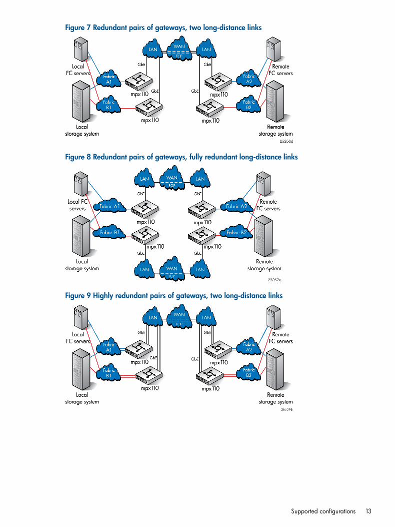
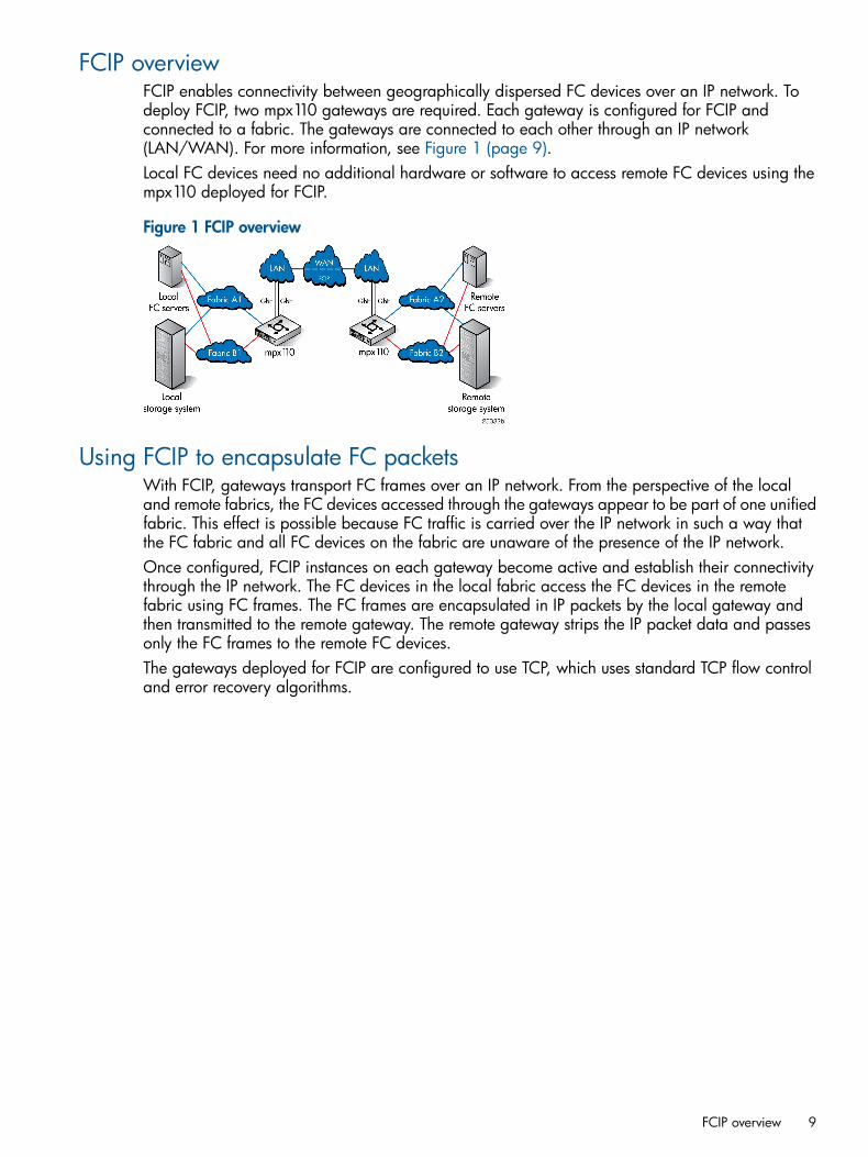
Figure 7 Redundant pairs of gateways, two long-distance links
Figure 8 Redundant pairs of gateways, fully redundant long-distance links
Figure 9 Highly redundant pairs of gateways, two long-distance links
Supported configurations 13
Figure 10 Highly redundant pairs of gateways, fully redundant long-distance links
Figure 11 Basic configuration, MPX200 FCIP with remote IP Distance Gateway (mpx110)
14 Configuration rules and guidelines

Figure 12 shows a configuration using the mpx110 with FCIP and B-series switches with IntegratedRouting. This provides fabric isolation between the local and remote fabrics, enabling device accesswithout merging the fabrics. This can be implemented in all supported mpx110 FCIP configurationsusing B-series Fibre Channel switches with Integrated Routing or B-series routers configured forFibre Channel routing.
Figure 12 mpx110 FCIP with B-series Integrated Routing
WANFCIP
LAN LAN
GbE GbE
26626a
Fabric A2Fabric A1
Localstorage system
Remotestorage system
Local FCservers
RemoteFC servers
FC1
FC2
GE1
GE2
MGMTIOIOI
!
HP StorageWorksmpx100
mpx110
FC1
FC2
GE1
GE2
MGMTIOIOI
!
HP StorageWorksmpx100
mpx110
EX E
Supported configurations 15
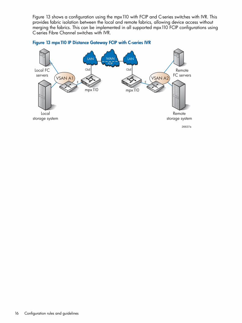
Figure 13 shows a configuration using the mpx110 with FCIP and C-series switches with IVR. Thisprovides fabric isolation between the local and remote fabrics, allowing device access withoutmerging the fabrics. This can be implemented in all supported mpx110 FCIP configurations usingC-series Fibre Channel switches with IVR.
Figure 13 mpx110 IP Distance Gateway FCIP with C-series IVR
VSAN A1
WANFCIP
LAN LAN
GbE GbE
26637a
Localstorage system
Remotestorage system
Local FCservers
RemoteFC servers
FC1
FC2
GE1
GE2
MGMTIOIOI
!
HP StorageWorksmpx100
mpx110
FC1
FC2
GE1
GE2
MGMTIOIOI
!
HP StorageWorksmpx100
mpx110
E EVSAN A2
16 Configuration rules and guidelines
HP Continuous Access P6000/EVA 3-site configurationsThis section describes the following HP Continuous Access P6000/EVA 3-site configurations:• HP Continuous Access EVA 3-site configuration with four gateways (page 17)
• HP Continuous Access EVA 3-site configuration with six gateways (page 17)
• HP Continuous Access EVA 3-site configuration with eight gateways (page 19)
• (page 20)The first three configurations provide a fan-in or fan-out relationship between the sites. The fourthconfiguration provides a peer-to-peer relationship between all sites.Figure 14 (page 17) shows connectivity for three sites using four mpx110 gateways, whichimplements the minimum-level and lowest-cost connectivity for a 3-site configuration. Figure 15 (page18) shows additional connectivity and redundancy using six mpx110 gateways. Figure 16 (page19) shows the highest level of 3-site connectivity using eight mpx110 gateways.Figure 17 (page 20) is similar to Figure 15 (page 18), with additional connectivity to allow forreplication between Site 2 and Site 3.The following configuration rules apply to Figure 14 (page 17) through Figure 16 (page 19)(fan-in/fan-out relationships):• For Site 1, Site 2 or Site 3 can function as the remote site.
• For Site 2 or Site 3, Site 1 can function as the remote site.
• Replication between Site 2 and Site 3 is not supported.The following configuration rules apply to Figure 17 (page 20) (peer-to-peer relationship):• For Site 1, Site 2 or Site 3 can function as the remote site.
• For Site 2, Site 1 or Site 3 can function as the remote site.
• For Site 3, Site 1 or Site 2 can function as the remote site.
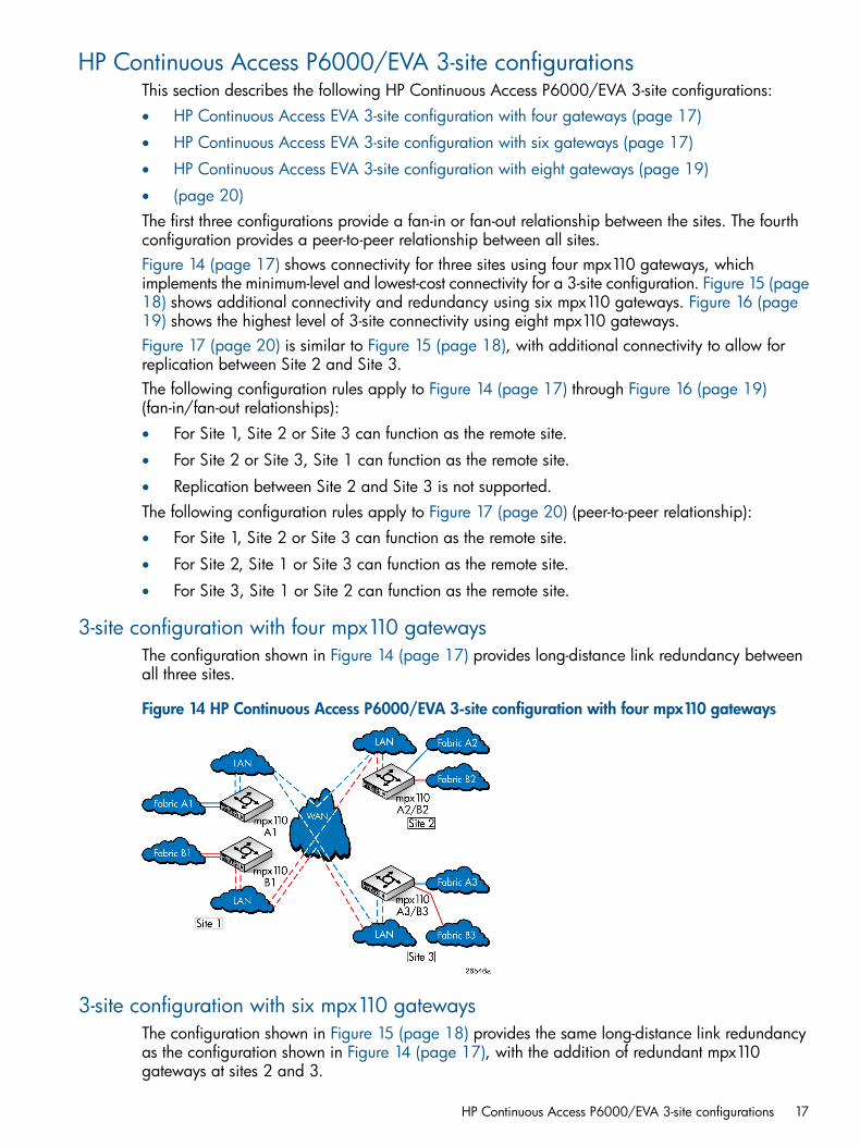
3-site configuration with four mpx110 gatewaysThe configuration shown in Figure 14 (page 17) provides long-distance link redundancy betweenall three sites.
Figure 14 HP Continuous Access P6000/EVA 3-site configuration with four mpx110 gateways
3-site configuration with six mpx110 gatewaysThe configuration shown in Figure 15 (page 18) provides the same long-distance link redundancyas the configuration shown in Figure 14 (page 17), with the addition of redundant mpx110gateways at sites 2 and 3.
HP Continuous Access P6000/EVA 3-site configurations 17
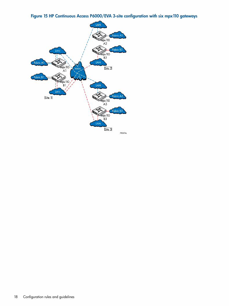
Figure 15 HP Continuous Access P6000/EVA 3-site configuration with six mpx110 gateways
18 Configuration rules and guidelines
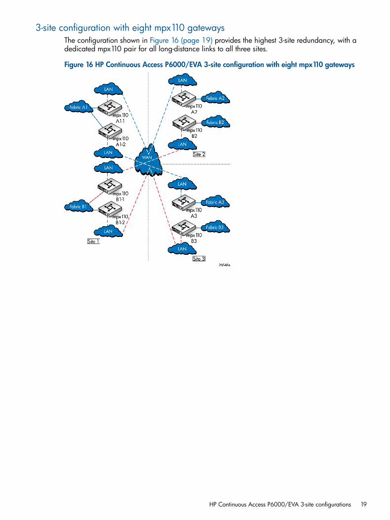
3-site configuration with eight mpx110 gatewaysThe configuration shown in Figure 16 (page 19) provides the highest 3-site redundancy, with adedicated mpx110 pair for all long-distance links to all three sites.
Figure 16 HP Continuous Access P6000/EVA 3-site configuration with eight mpx110 gateways
HP Continuous Access P6000/EVA 3-site configurations 19
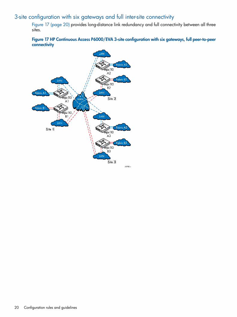
3-site configuration with six gateways and full inter-site connectivityFigure 17 (page 20) provides long-distance link redundancy and full connectivity between all threesites.
Figure 17 HP Continuous Access P6000/EVA 3-site configuration with six gateways, full peer-to-peerconnectivity
20 Configuration rules and guidelines

Configuration rules and guidelinesThe following sections define the configuration rules for using the mpx110 gateways for FCIP.
General configuration rulesThe following general configuration rules apply:
• All mpx110 configurations require a minimum of two mpx110 gateways, or one mpx110and one MPX200 Multifunction Router with an FCIP license, one local and one remote,connected through an IP network.
• The mpx110 gateway must connect to another mpx110 or an mpx200 Multifunction Routerwith an FCIP license. HP does not support FCIP connectivity between other gateway models.
• The mpx110 gateway is supported for FCIP extension with HP P9000 and P6000 ContinuousAccess (see EVA storage system rules and guidelines (page 21) and XP storage system rulesand guidelines (page 22)), and P10000/3PAR Remote Copy software.
NOTE: For current support, see SPOCK at http://www.hp.com/storage/spock. You must signup for an HP Passport to enable access.
Operating system and multipath supportThe mpx110 gateway is supported using FCIP with all operating systems and multipath softwaresupported by HP. For more information, see the HP SAN Design Reference Guide, available athttp://www.hp.com/go/SDGManuals.
P6000/EVA storage system rules and guidelinesObserve the following P6000/EVA storage system rules and guidelines:
• P6350/P6300/P6550/P6500
• The mpx110 gateway configured for FCIP is supported for use with the following HP ContinuousAccess P6000/EVA storage systems:
◦ EVA4400/4400 with embedded switch
◦ EVA4000/4100/6000/6100/8000/8100
◦ EVA6400/8400
• The mpx110 gateway is supported for use in all HP-supported P6000 Continuous Accessconfigurations, including the standard two-fabric, five-fabric, and six-fabric configurations.
• HP P6000 Continuous Access supports RCS and non-RCS LUNs with FCIP extension.
• HP mpx110 gateway supports the minimum IP bandwidth/maximum DR groups.Table 1 (page 22) defines the minimum IP bandwidth and maximum EVA DR groups for EVA XCSand VCS.
Configuration rules and guidelines 21

Table 1 Minimum IP bandwidth and maximum DR groups
Minimum IP bandwidth and maximum DR groups1Gateway pair
Single or shared IP link latency (0 to 100 ms one-way)Dual fabric latency (0 to 100 ms one-way)
Minimum: At least 4 Mb/s for 1 DR groupRecommended: At least 10 Mb/s for 1 to 5 DR groups
Minimum: At least 2 Mb/s for 1 DR groupRecommended: At least 5 Mb/s for 1 to 5 DR groups
IP DistanceGateway(mpx110)1 1 Gb/s IP bandwidth can have up to 128 DR groups with VCS 4.x, and up to 256 DR groups with XCS.
P6000/EVA storage system softwareThe mpx110 gateway is supported with current P6000/EVA storage software applications suchas HP P6000 Continuous Access, Command View EVA, Business Copy, SSSU, and ReplicationSolutions Manager.
P9000/XP storage system rules and guidelinesObserve the following P9000/XP storage system rules and guidelines:
• Supported P9000/XP models are P9500/XP24000/20000 and XP12000/10000, withsupported firmware levels. For more information, see SPOCK at http://www.hp.com/storage/spock.
• The mpx110 gateway configured for FCIP is supported for use with P9000/XP ContinuousAccess Sync, Async, and Journal.
• The mpx110 gateway is supported for use in all HP-supported P9000/XP Continuous AccessFCIP configurations. For more information, see the P9000/XP Continuous Access documentationand the HP SAN Design Reference Guide, available at http://www.hp.com/go/SDGManuals.
• A P9000/XP storage system requires a minimum IP bandwidth of 16 Mb/s per path. Themaximum latency is 100 ms round-trip.
P9000/XP storage system softwareThe mpx110 gateway is supported with current versions of P9000/XP storage software applications,such as XP Continuous Access, Command View XP, Continuous Access Journal XP, Business CopyXP, and XP Array Manager.
Fibre Channel switch and firmware supportThe mpx110 is compatible with the following Fibre Channel switches:• B-series 8 Gb/s, 4 Gb/s, and 2 Gb/s Fibre Channel switches
• C-series 8 Gb/s, 4 Gb/s, and 2 Gb/s Fibre Channel switches
• H-series 8 Gb/s Fibre Channel switches
NOTE: For current support, see SPOCK at http://www.hp.com/storage/spock. You mustsign up for an HP Passport to enable access.
FC switch requirementsThe following additional B-series, C-series, and H-series FC switch requirements must be observed:
• Local and remote mpx110 gateway pairs must be connected to the same Fibre Channel switchproduct line series.
• The maximum distance between an mpx110 and a Fibre Channel switch is 300 meters at 2Gb/s.
NOTE: The mpx110 Fibre Channel ports operate at 2 Gb/s.
22 Configuration rules and guidelines
IP network requirementsHP requires that the following standards be met for the IP network:
• Supported network protocols are TCP/IP IPv4 and IPv6 Ethernet 1,000 Mb/s.See EVA storage system rules and guidelines (page 21) and XP storage system rules andguidelines (page 22) for minimum IP bandwidth requirements.
• For mpx110 IP data—Local and remote pairs are supported for up to 100 ms of IP networkdelay one-way, or 200 ms round-trip for HP Continuous Access P6000. HP requires dedicatedIP bandwidth (see Table 2 (page 24)). For P9000 Continuous Access, the maximum distanceand delay is based on the replication mode. See “P9000/XP and VA storage system rules”in the HP SAN Design Reference Guide.
• For mpx110 IP management—LAN and WAN are supported.
Configuration rules and guidelines 23
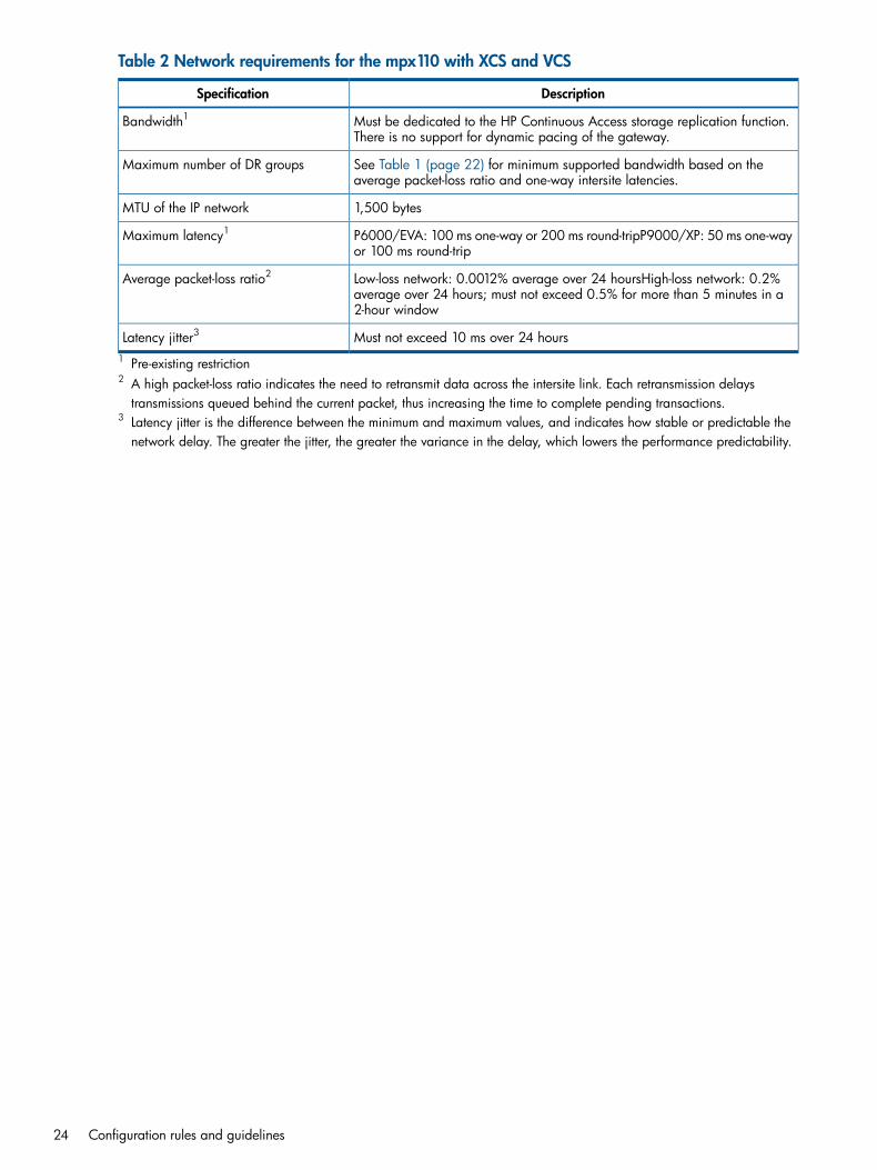
Table 2 Network requirements for the mpx110 with XCS and VCS
DescriptionSpecification
Must be dedicated to the HP Continuous Access storage replication function.There is no support for dynamic pacing of the gateway.
Bandwidth1
See Table 1 (page 22) for minimum supported bandwidth based on theaverage packet-loss ratio and one-way intersite latencies.
Maximum number of DR groups
1,500 bytesMTU of the IP network
P6000/EVA: 100 ms one-way or 200 ms round-tripP9000/XP: 50 ms one-wayor 100 ms round-trip
Maximum latency1
Low-loss network: 0.0012% average over 24 hoursHigh-loss network: 0.2%average over 24 hours; must not exceed 0.5% for more than 5 minutes in a2-hour window
Average packet-loss ratio2
Must not exceed 10 ms over 24 hoursLatency jitter3
1 Pre-existing restriction2 A high packet-loss ratio indicates the need to retransmit data across the intersite link. Each retransmission delaystransmissions queued behind the current packet, thus increasing the time to complete pending transactions.
3 Latency jitter is the difference between the minimum and maximum values, and indicates how stable or predictable thenetwork delay. The greater the jitter, the greater the variance in the delay, which lowers the performance predictability.
24 Configuration rules and guidelines
IP performance tuningThe mpx110 supports Fibre Channel service at transmission rates of 1 Gb/s or 2 Gb/s with amaximum frame size of 2,148 bytes. It supports Ethernet service at transmission rates of 1,000 or100 Mb/s with an MTU size between 1,000 and 9,000 bytes (jumbo frames). Related performancecharacteristics include the following:
• Distance (page 25)
• Bandwidth per route (page 25)
• Latency (page 25)
• MTU/Jumbo frames (page 25)
• Compression (page 26)
• TCP Window size/scaling performance tuning (page 26)
DistanceConsider the physical distance between the mpx110 gateways. This is usually measured in RTT.The RTT can be anywhere from less than 1 millisecond to as great as 200 milliseconds.
Bandwidth per routeBandwidth is a measure of the volume of data that can be transmitted at a given transmission rate.WAN data rates range from 1.5 Mb/s (T1) to greater than 600 Mb/s (OC-12). The propermpx110 bandwidth setting is determined based on the bandwidth available for each FCIP route,irrespective of the total bandwidth and physical speed of the link.To determine the proper mpx110 bandwidth setting, start with the total bandwidth of the WANlink. Adjust this number based on the guaranteed allocated FCIP bandwidth, then further adjustthis number if the number of FCIP routes configured is greater than one. For example, if the WANlink is 45 Mb/s, and 15 Mb/s is allocated to network traffic, the remaining 30 Mb/s is availablefor FCIP. If in this example the mpx110 is configured for two routes, based on the 30 Mb/s totalbandwidth available for FCIP, you would set the mpx110 bandwidth parameter to 15, the availablebandwidth for each FCIP route.HP P9000 and P6000 Continuous Access replication solutions require dedicated bandwidth forthe intersite link. If other applications share the intersite link, some method of QoS must be usedto ensure that the replication application has uncontested access to the allocated bandwidth.
NOTE: Setting the bandwidth per route parameter higher than the actual bandwidth availablefor each route results in a decrease in performance; the optimal setting matches the bandwidthper route setting to the actual bandwidth available to each FCIP route.
LatencyLatency is the amount of time a packet takes to traverse the network from source to destination.
MTU/Jumbo framesFor MTU size there are 3 settings, Normal (1500 bytes), Jumbo (9000 bytes) and Other, whereyou are then prompted for a value between 1000 and 9000.• Normal: Typically MTU should be set to the default of 1500; rarely do WAN networks support
MTU sizes greater than 1500.• Jumbo - Jumbo frames can enhance the IP performance of the mpx110. Before enabling jumbo
frames, ensure that all switches in the IP path are configured for jumbo frames.
IP performance tuning 25
NOTE: Jumbo frames are not supported for use with HP P9000 or P6000 Continuous Access.
• Other: Allows you to configure the MTU size to a value between 1000 and 9000 bytes.Encryption products on the WAN link often add some number of additional bytes to eachpacket, so it may be necessary to decrease the mpx110 MTU size setting to between 1450and 1200. This accommodates the additional bytes, while maintaining a total MTU size of1500 or less. Keeping the total MTU size to a maximum of 1500 ensures a single FibreChannel frame (2112 bytes) will fit within two Ethernet packets, resulting in optimalperformance.
CompressionThe mpx110 integrates a software compression option. Enable compression for IP fabrics with anRTT greater than or equal to 50 ms, or guaranteed WAN bandwidth of less than or equal to 45Mb/s. See TCP window size recommendations (page 28) for compression options for specificnetwork rates and RTT.
TCP window size/scaling performance tuningThe mpx110 performance is maximized when properly configured. Knowing the RTT (distance)between mpx110 gateways and the WAN effective data rate (connection type) allows the gatewaysto be tuned for optimal performance. See (page 26).
Modifying the window size and scaling factorThe mpx110 window size can be set to a maximum of 32 KB. The scaling factor is used as amultiplier to increase the window size above 32 KB. Modify the window size and scaling factorin the mpx110 gateway pairs based on the WAN RTT and link speed. To determine the appropriatewindow size setting, use the pre-populated tables or a formula.If the recommended TCP window size scale factor for a given RTT and WAN link speed is notshown in Table 4 (page 28) through Table 10 (page 31), use the following formula:(RTT (ms) x link rate (Kb/s) x (1 byte/8 bits) = minimum window size (MWS)Then, convert the MWS to a recommended scale factor by dividing it by the default window size(32,768 bytes). Use Table 3 (page 27) to determine the scale factor.
26 Configuration rules and guidelines

Table 3 TCP window size scale factors
Scale factorMWS scale result
00 to 2
12 to 4
24 to 8
38 to 16
416 to 32
532 to 64
664 to 128
7128 or greater
IP performance tuning 27

TCP window size recommendationsTable 4 (page 28) through Table 10 (page 31) provide TCP window scaling factor and windowsize settings for specific WAN environments.
NOTE: The TCP window size recommendations listed in Table 4 (page 28) through Table 10 (page31) are based on low-loss networks (0.0012% average packet-loss ratio over 24 hours). Forhigher-loss, longer-latency networks, you should reduce the recommended window size and scalingfactor by one setting to compensate for the increased number of packet retransmissions.
Table 4 T1 / DS-1: 1.554 Mb/s
Compressionrecommendations
Scaling factorTotal windowsize (bytes)
Round-trip time
ON164 K200
ON032 K100
ON032 K50
ON032 K25
ON032 K20
ON032 K15
ON032 K10
ON032 K5
ON032 K2.5
ON032 K1 or less
28 Configuration rules and guidelines
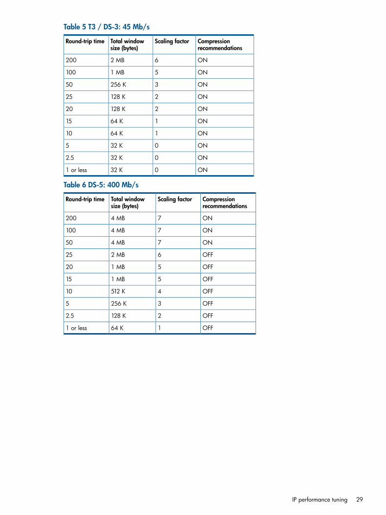
Table 5 T3 / DS-3: 45 Mb/s
Compressionrecommendations
Scaling factorTotal windowsize (bytes)
Round-trip time
ON62 MB200
ON51 MB100
ON3256 K50
ON2128 K25
ON2128 K20
ON164 K15
ON164 K10
ON032 K5
ON032 K2.5
ON032 K1 or less
Table 6 DS-5: 400 Mb/s
Compressionrecommendations
Scaling factorTotal windowsize (bytes)
Round-trip time
ON74 MB200
ON74 MB100
ON74 MB50
OFF62 MB25
OFF51 MB20
OFF51 MB15
OFF4512 K10
OFF3256 K5
OFF2128 K2.5
OFF164 K1 or less
IP performance tuning 29
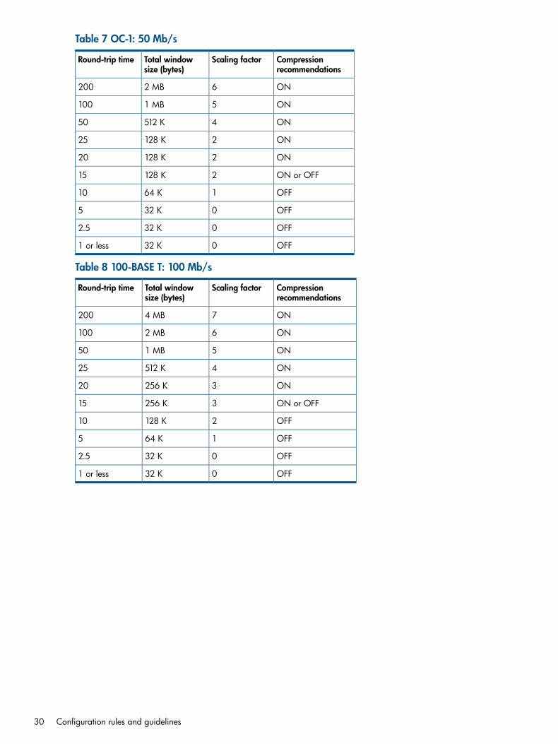
Table 7 OC-1: 50 Mb/s
Compressionrecommendations
Scaling factorTotal windowsize (bytes)
Round-trip time
ON62 MB200
ON51 MB100
ON4512 K50
ON2128 K25
ON2128 K20
ON or OFF2128 K15
OFF164 K10
OFF032 K5
OFF032 K2.5
OFF032 K1 or less
Table 8 100-BASE T: 100 Mb/s
Compressionrecommendations
Scaling factorTotal windowsize (bytes)
Round-trip time
ON74 MB200
ON62 MB100
ON51 MB50
ON4512 K25
ON3256 K20
ON or OFF3256 K15
OFF2128 K10
OFF164 K5
OFF032 K2.5
OFF032 K1 or less
30 Configuration rules and guidelines
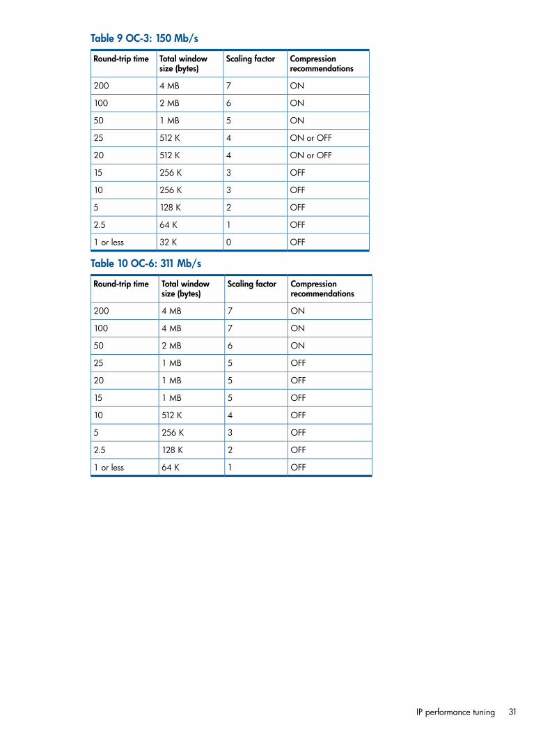
Table 9 OC-3: 150 Mb/s
Compressionrecommendations
Scaling factorTotal windowsize (bytes)
Round-trip time
ON74 MB200
ON62 MB100
ON51 MB50
ON or OFF4512 K25
ON or OFF4512 K20
OFF3256 K15
OFF3256 K10
OFF2128 K5
OFF164 K2.5
OFF032 K1 or less
Table 10 OC-6: 311 Mb/s
Compressionrecommendations
Scaling factorTotal windowsize (bytes)
Round-trip time
ON74 MB200
ON74 MB100
ON62 MB50
OFF51 MB25
OFF51 MB20
OFF51 MB15
OFF4512 K10
OFF3256 K5
OFF2128 K2.5
OFF164 K1 or less
IP performance tuning 31
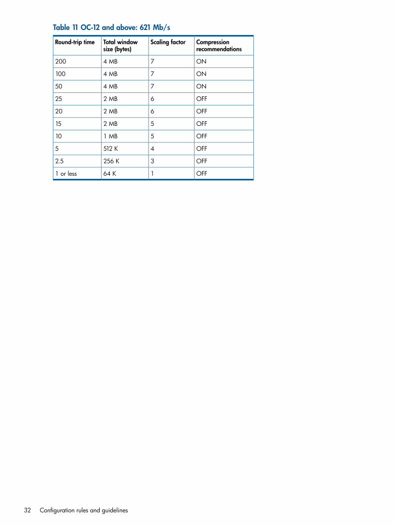
Table 11 OC-12 and above: 621 Mb/s
Compressionrecommendations
Scaling factorTotal windowsize (bytes)
Round-trip time
ON74 MB200
ON74 MB100
ON74 MB50
OFF62 MB25
OFF62 MB20
OFF52 MB15
OFF51 MB10
OFF4512 K5
OFF3256 K2.5
OFF164 K1 or less
32 Configuration rules and guidelines
3 Installation and upgradesThis chapter contains the information needed to install, configure, and upgrade the mpx110.
Verifying mpx110 requirementsObtain the following (one of each, unless otherwise noted) for the local and remote site:
• HP IP Distance Gateway (mpx110), Part Number: AG680A
• HP P9000 or P6000 Continuous Access software or P10000/3PAR Remote Copy softwareEVA4400/4400 with embedded switch, EVA4000/4100/6000/6100/8000/8100,EVA6400/8400, P6350/P6300/P6550/P6500, orP9500/XP24000/20000/12000/10000 storage system or P10000/3PAR V-Class, F-Class,T-Class storage systems
• FC fabrics consisting of HP B-series, C-series, or H-series switches
• Cat 5e network cable, two per site
• Optical SFPs and FC cables, two per siteAdditional optional equipment (one of each, unless otherwise noted) for the local and remote site:
• HP IP Distance Gateway Upgrade (mpx110 for redundancy), Part Number: AG681A
• Optical SFPs and FC cables, two per site
NOTE: For the latest information about the minimum system requirements, see the HP IP DistanceGateway release notes, available at http://www.hp.com/support/manuals. Under Storage, selectStorage Networking, and then under Routers/Gateways/Multiplexers, select HP IP DistanceGateway.
Verifying mpx110 requirements 33
Pre-installation checklistBefore starting the configuration process, contact your System Administrator for the followingmpx110 parameters:
• Symbolic Name of the mpx110
• IP address, subnet mask and gateway for the mpx110 management port (if not using DHCP)
• IP address, subnet mask and gateway for the GE1 port
• IP address of the remote mpx110 that connects to the GE1 port
• IP address, subnet mask and gateway for the GE2 port (if applicable)
• IP address of the remote mpx110 that connects to the GE2 port (if applicable)
• FCIP link parameters (specifically, Guaranteed Bandwidth, Round-Trip-Delay, Quality OfService, and VLAN/Priority)For more information, see (page 41).
• mpx110 serial console cable adapter
• HP mpx Manager software (optional)
• The default TCP port used by the mpx110 is 3225. To ensure that the FCIP link is formedcorrectly, make sure that any firewalls have port 3225 unblocked before connecting thempx110s.
Rack mounting the mpx110
WARNING! Mount the mpx100/100b in the rack so that the weight is evenly distributed. Anunevenly loaded rack can become unstable possibly resulting in equipment damage or personalinjury.This product is supplied with a three-wire cable and plug for the user's safety. Use this power cablein a properly grounded outlet to avoid electrical shock. An electrical outlet that is not correctlywired could place hazardous voltage on metal parts of the switch chassis. It is the responsibilityof the customer to ensure the outlet is correctly wired and grounded to prevent electrical shock.If the chassis is installed in a closed or multi-rack assembly, the operating temperature of the rackenvironment may be greater than the ambient temperature, Be sure to install the chassis in anenvironment that is compatible with the maximum ambient rated temperature.
You need a Phillips head screwdriver to rack mount the mpx110. You also need to make sure thatthe operating temperature inside the rack enclosure does not exceed the maximum rated ambienttemperature (70° C), especially if the mpx110 is mounted in a closed or multi-unit rack assembly.1. Assemble two slide brackets (right and left) on the back ends of the C-Shelf, using the four
hole nut plates:
NOTE: The rear of the C-Shelf is the end without the knurled thumbscrews.
a. Mount the C-Shelf with the open side up.b. Fit the slide bracket along the 1U side at the back of the C-Shelf with its screw hole tab
pointing outboard and its lip supporting the C-Shelf. Mount both right-hand and left-handslide brackets.
c. Attach the nut plate outside the slide bracket with the dimpled threaded holes pointingoutboard.
34 Installation and upgrades
d. Place two screws (10-32 Pan 0.625 XRCS) through the two holes at the back of theC-Shelf, through the slide plate slots and loosely into the front two threaded holes of thenut plate.
e. Repeat steps a through d with the opposite hand slide bracket.2. Install the C-Shelf assembly into the rack:
a. Locate a clear 1U area space within the rack.
NOTE: The 1U space in a rack includes three rail mounting holes; however, the rackholes are not evenly spaced. For best installation the C-Shelf can be centered in a 1Uspace. To locate the center, find a hole that is 5/8" on center from the hole immediatelyabove and below. The two holes above and below this center are only 1/2" on centerfrom their adjacent holes.
b. At the front of the rack, in the center mounting holes, install two nuts (KEPs 10-32, 0.375AFCSZ EXT).
c. Carefully supporting the C-Shelf assembly, loosely thread the knurled thumbscrews throughthe rack into the two nuts just installed.
d. Go to the back of the rack and position a slide bracket next to the corresponding holesat the back of the rack. Slide the bracket to the rear until the threaded screw hole tabsare flush with the inside of the rack rail.
e. Insert two screws (10-32 Pan 0.325 XRCS screws) through the rack rail into the threadedscrew hole tab and tighten loosely.
f. Repeat step e with the other side of the C-Shelf assembly.g. Tighten all four screws (10-32 Pan 0.625 XRCS screws) at the rear of the C-Shelf assembly.h. Tighten the front two knurled thumbscrews.i. Tighten the two screws (10-32 Pan 0.625 XRCS screws) at each side of the back of the
C-Shelf assembly.3. Install the mpx110 into one of the two available positions in the C-Shelf:
a. As the mpx110 slides in there are two tabs at the front and rear that catch and ensurethat the mpx110 is firmly seated to the C-Shelf assembly. Take care to ensure that thempx110 is engaged in all four tabs. To ensure that all four of the tabs engage, you mayneed to hold both the mpx110 and the C-Shelf assembly as you slide it in the last inch.
NOTE: The front of the mpx110 is the end with the connections and faces the rear ofthe equipment rack. The mpx110 slides in from the front of the equipment rack.
b. Once the rear of the mpx110 is flush with the front of the C-Shelf assembly and all fourclips are engaged, the bezel can be snapped on the front.
Installing the SFPsYou will need an SFP transceiver for each of the FC ports that connect to an FC switch.To install the SFPs:1. Align the SFP transceiver so that the key is oriented correctly to the port. Transceivers are
keyed so that they can only be inserted one way.2. Insert the transceiver into the port.3. Press gently until the transceiver snaps into place.
ManagementThe GUI application and CLI execute on a management workstation that provides for theconfiguration, control, and maintenance of the mpx110. Supported platforms include MicrosoftWindows, Solaris, and Linux. The GUI application is installed and executed on the workstation.
Installing the SFPs 35
The mpx110 supports the following management interfaces:
• mpx Manager GUI—Executes on a management workstation
• CLI—Executes on the mpx110 and is accessed using Telnet or the serial port (see Command-lineinterface (page 80))
• SNMP—Provides mpx110 status, traps, and alerts (see Simple Network ManagementProtocol (page 132))
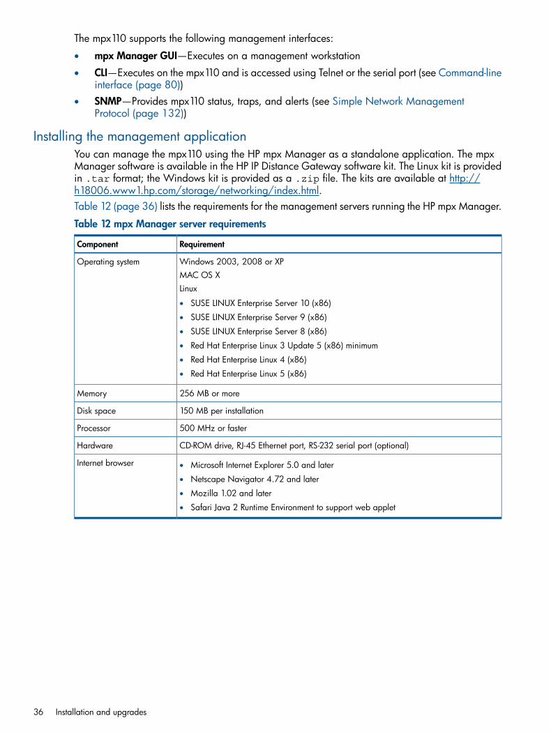
Installing the management applicationYou can manage the mpx110 using the HP mpx Manager as a standalone application. The mpxManager software is available in the HP IP Distance Gateway software kit. The Linux kit is providedin .tar format; the Windows kit is provided as a .zip file. The kits are available at http://h18006.www1.hp.com/storage/networking/index.html.Table 12 (page 36) lists the requirements for the management servers running the HP mpx Manager.
Table 12 mpx Manager server requirements
RequirementComponent
Windows 2003, 2008 or XPOperating systemMAC OS XLinux
• SUSE LINUX Enterprise Server 10 (x86)
• SUSE LINUX Enterprise Server 9 (x86)
• SUSE LINUX Enterprise Server 8 (x86)
• Red Hat Enterprise Linux 3 Update 5 (x86) minimum
• Red Hat Enterprise Linux 4 (x86)
• Red Hat Enterprise Linux 5 (x86)
256 MB or moreMemory
150 MB per installationDisk space
500 MHz or fasterProcessor
CD-ROM drive, RJ-45 Ethernet port, RS-232 serial port (optional)Hardware
Internet browser • Microsoft Internet Explorer 5.0 and later
• Netscape Navigator 4.72 and later
• Mozilla 1.02 and later
• Safari Java 2 Runtime Environment to support web applet
36 Installation and upgrades
HP mpx Manager for WindowsYou can install HP mpx Manager on a Windows server. To install the HP mpx Manager applicationfrom the HP IP Distance Gateway installation file:1. Close all programs currently running, and then unzip the executable file to the system.2. Double-click the executable to start the installation.
HP mpx Manager for LinuxThis section describes how to install HP mpx Manager on a Linux server.
NOTE: In the following procedure, replace n.n.nn and n.n.nnbnnn with a file name (forexample, 2.0.30 and 2.0.30b112).
1. Download the hpmpx_n.n.nn_linux_install.tar file from http://h18006.www1.hp.com/storage/networking/index.html. The .tar file contains the .binfile and a GUI install README file.
2. Unpack the file to a temporary directory. For example:tar -zxvf hpmpx_n.n.nn_linux_install.tar
3. Enter the following to start the install:./hpmpxn.n.nnbnn_linux_install.bin.A chmod may be necessary prior to execution.
4. Follow the installation instructions on the screen and note the installation location. The defaultdirectory is /opt/Hewlett-Packard/mpxManager.
Setting mpx110 management port parameters
NOTE: If you are using Telnet to configure the mpx110 for the first time, your workstation IPaddress must be 10.0.0.x, where x is a number other than 1, and the subnet mask is 255.0.0.0.
To set the initial mpx110 configuration parameters:1. Connect the mpx110 management port to a workstation to configure the initial mpx110
parameters. You can connect the mpx110 management port to an IP switch or hub, directlyto the workstation with an Ethernet crossover cable to the management port, or to the RS-232port with a serial cable.
NOTE: If connecting to the mpx110 serial port, the terminal settings are 115200 baud, 8bit, 1 stop bit, no parity, and no flow control.
2. Attach one end of the AC power cord to the mpx110 and the other end to the PDU.3. Verify that the Heartbeat LED is flashing (once per second) and that the System Fault LED does
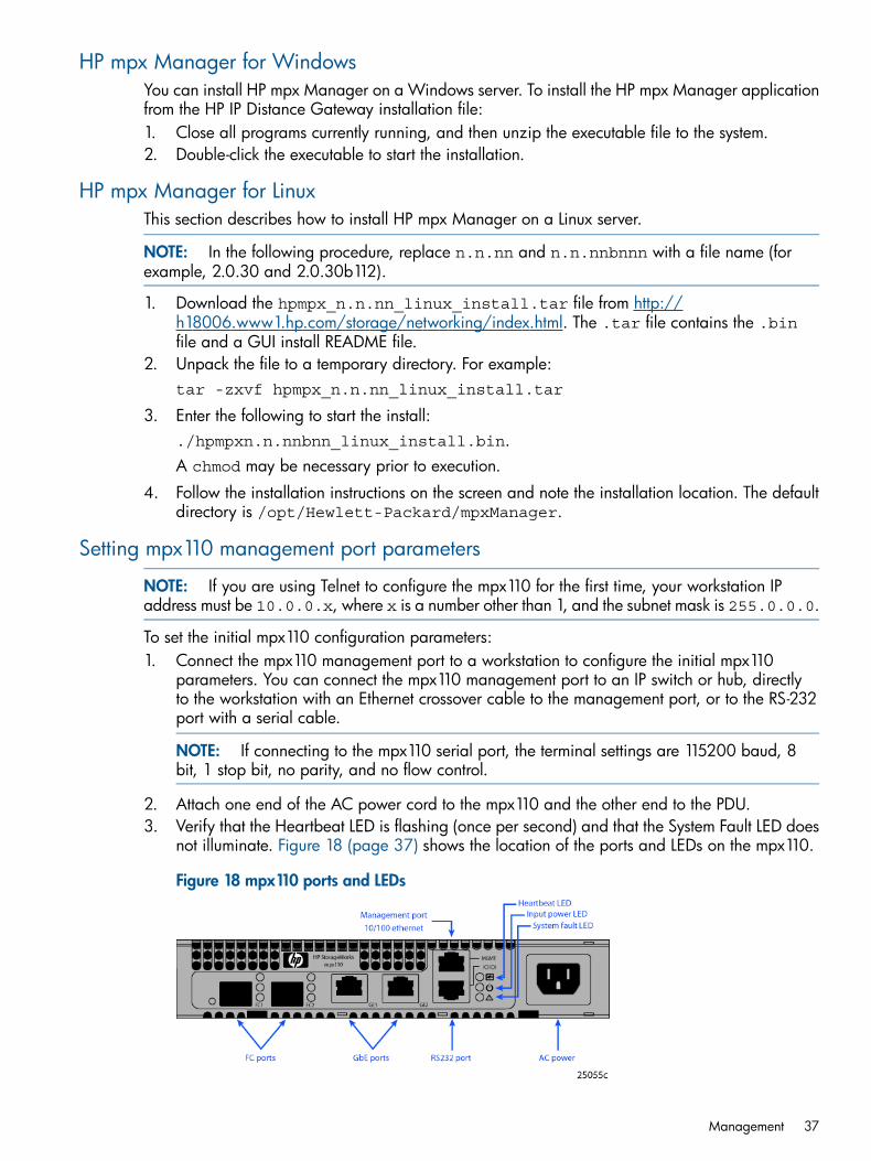
not illuminate. Figure 18 (page 37) shows the location of the ports and LEDs on the mpx110.
Figure 18 mpx110 ports and LEDs
Management 37

See Diagnostics and troubleshooting (page 48) for a description of the LED fault indications.4. Telnet to the mpx110 using IP address 1.0.0.1, or use a terminal emulation program (serial
cable) from your workstation (see Figure 19 (page 38)):a. Enter guest at the login prompt.b. Enter password at the password prompt.
NOTE: HP recommends changing the mpx110 guest password after logging in.
Figure 19 Setting IP addressing using Telnet
5. Enter admin start at the mpx110 prompt.6. Enter the default password, config.
NOTE: HP recommends that you change the mpx110 Admin password after logging in.
7. Enter the command set mgmt to set initial parameters.8. Follow the on-screen prompts to define the following parameters (or press Enter to accept
default parameters):• Mode (HP highly recommends using static address, Option 0)
• IPv4/IPv6 address (Because the FCIP ports require dedicated bandwidth, HP recommendsthat the IP address for the management port be in a different subnet than the FCIP ports.)
• Subnet mask
• Default gateway or routerThe management port is now configured with the appropriate IP address and networkparameters.
IMPORTANT: At this point, the Telnet session terminates. To restart the Telnet session, usethe IP address you just assigned to the management port.
38 Installation and upgrades

Configuring Fibre Channel switch settings for the mpx110This section provides HP Fibre Channel switch parameters. Modify the switch settings listed belowbased on the switch product line used. All settings apply to HP P9000 and P6000 ContinuousAccess unless noted otherwise.
B-series Fibre Channel switch parametersExecute the commands in Table 13 (page 39) for all switches that will use the FCIP link.
Table 13 Settings for B-series switches
HP storage systemCommand
P6000/EVAP9000/XP
B-Switch# switchdisable
B-Switch# iodsetP10000/3PAR
B-Switch# aptpolicy [1 or 3] (See NOTE below.)
B-Switch# portcfgislmode [slot/port],1
(Set for all mpx110 connected switch ports, regardless of the storage type)
B-Switch# portcfggport [slot/port],1
(Set for all mpx110 switch ports)
B-Switch# switchenable
Configuring Fibre Channel switch settings for the mpx110 39
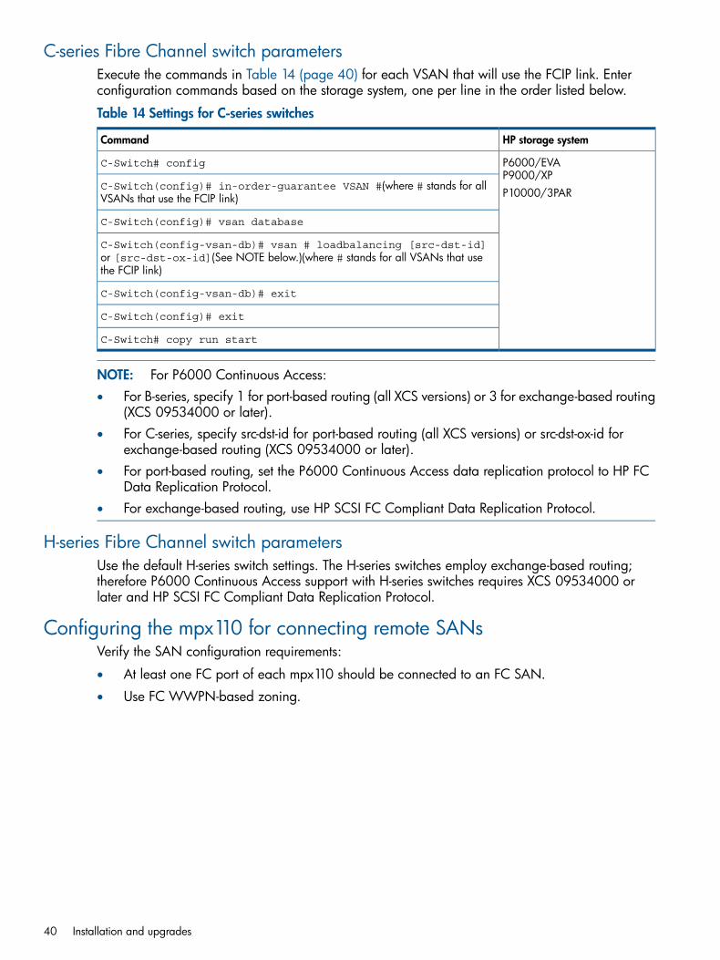
C-series Fibre Channel switch parametersExecute the commands in Table 14 (page 40) for each VSAN that will use the FCIP link. Enterconfiguration commands based on the storage system, one per line in the order listed below.
Table 14 Settings for C-series switches
HP storage systemCommand
P6000/EVAP9000/XP
C-Switch# config
C-Switch(config)# in-order-guarantee VSAN #(where # stands for allVSANs that use the FCIP link) P10000/3PAR
C-Switch(config)# vsan database
C-Switch(config-vsan-db)# vsan # loadbalancing [src-dst-id]or [src-dst-ox-id](See NOTE below.)(where # stands for all VSANs that usethe FCIP link)
C-Switch(config-vsan-db)# exit
C-Switch(config)# exit
C-Switch# copy run start
NOTE: For P6000 Continuous Access:• For B-series, specify 1 for port-based routing (all XCS versions) or 3 for exchange-based routing
(XCS 09534000 or later).• For C-series, specify src-dst-id for port-based routing (all XCS versions) or src-dst-ox-id for
exchange-based routing (XCS 09534000 or later).• For port-based routing, set the P6000 Continuous Access data replication protocol to HP FC
Data Replication Protocol.• For exchange-based routing, use HP SCSI FC Compliant Data Replication Protocol.
H-series Fibre Channel switch parametersUse the default H-series switch settings. The H-series switches employ exchange-based routing;therefore P6000 Continuous Access support with H-series switches requires XCS 09534000 orlater and HP SCSI FC Compliant Data Replication Protocol.
Configuring the mpx110 for connecting remote SANsVerify the SAN configuration requirements:
• At least one FC port of each mpx110 should be connected to an FC SAN.
• Use FC WWPN-based zoning.
40 Installation and upgrades
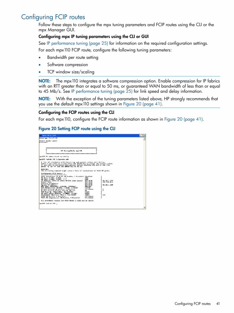
Configuring FCIP routesFollow these steps to configure the mpx tuning parameters and FCIP routes using the CLI or thempx Manager GUI.Configuring mpx IP tuning parameters using the CLI or GUISee IP performance tuning (page 25) for information on the required configuration settings.For each mpx110 FCIP route, configure the following tuning parameters:
• Bandwidth per route setting
• Software compression
• TCP window size/scaling
NOTE: The mpx110 integrates a software compression option. Enable compression for IP fabricswith an RTT greater than or equal to 50 ms, or guaranteed WAN bandwidth of less than or equalto 45 Mb/s. See IP performance tuning (page 25) for link speed and delay information.
NOTE: With the exception of the tuning parameters listed above, HP strongly recommends thatyou use the default mpx110 settings shown in Figure 20 (page 41).
Configuring the FCIP routes using the CLIFor each mpx110, configure the FCIP route information as shown in Figure 20 (page 41).
Figure 20 Setting FCIP route using the CLI
Configuring FCIP routes 41

Configuring the FCIP routes using the mpx Manager GUI1. Invoke the mpx Manager previously installed on the computer (Figure 21 (page 42)).
Figure 21 Connection to mpx Manager
2. Click the Connect icon in the top left corner of the screen.3. Enter the mpx110 IP address, and then click the Connect button.4. Select the Wizard menu to run the FCIP Route Add wizard (Figure 22 (page 42)).
A warning message appears.
Figure 22 FCIP Route Add wizard
5. Click Yes to continue.The FC & GigE Port Selection screen appears.
6. Select the FC/GE ports to configure. As an option, you may enter the GE port speed and flowcontrol parameters. Click Next to continue.The Local & Remote IP Address screen appears.
42 Installation and upgrades
7. Enter the local GE port IP address, subnet mask, gateway and the IP address of the remotempx110. Click Next to continue.The TCP/IP Options screen appears.
8. Select the appropriate options for your configuration and ensure that the same options areselected on the remote port as well. Click Next to continue.The FCIP Option screen appears.
9. Select the appropriate options for your configuration and ensure that the same options areselected on the remote port as well. Click Finish to continue.The Security Check screen appears.
10. Enter the Admin password (default password is config). Click OK to continue.A message appears, indicating that the process for adding FCIP routes is now complete.
Configuring FCIP routes 43
Cabling the mpx110 Fibre Channel, GE, and management portsTo cable the mpx110:1. Connect the management port cable to the Ethernet network that is accessible from the
management server running the mpx Manager GUI.2. Connect cables to Fabric A1, Fabric B1, Fabric A2 and Fabric B2, as shown in the examples
in Supported configurations (page 11).
NOTE: Use a standard Cat 5e straight network cable to connect mpx110 GE ports to an IP switchport. Use a Cat 5e crossover network cable when directly connecting two mpx110s through theirrespective GE ports without an IP switch.
Verifying FCIP links and firmware versionTo verify the FCIP links and firmware version:1. To determine if a firmware upgrade is necessary, see the HP website:
http://www.hp.com/go/sanIf applicable, see Firmware upgrades (page 44).
2. Use the CLI or the GUI ping command to verify FCIP Link connectivity.3. Verify if FC switches have established an ISL over FCIP link.
Firmware upgradesUse the mpx Manager GUI or the CLI to install firmware upgrades.
CAUTION: Installing new firmware is disruptive because the mpx110 must be rebooted to activatethe new firmware. The reboot may result in incorrect data being transferred between devicesconnected to the mpx110. HP recommends suspending activity on the interfaces before activatingthe new firmware.
Using the mpx Manager GUI to upgrade firmwareTo upgrade firmware:1. Double-click the mpx110 in the topology display.2. In the Firmware Upload window, click the Select button to browse and select the firmware file
to be uploaded.3. Click the Start button to begin the firmware load process. A message appears warning you
that the mpx110 will be reset to activate the firmware.4. Click the OK to continue firmware installation, or click the Cancel button to cancel the firmware
installation.
Using the CLI to upgrade firmwareUsing the CLI involves transferring the firmware image file from a workstation to the mpx110, andthen issuing image unpack to install the new firmware image, as described in the followingsteps:1. At the workstation prompt, use the ftp command to go to the location on the mpx110 where
you want to transfer the firmware image. For example:C:\fwImage>ftp 172.17.137.190Connected to 172.17.137.190.220 (none)FTP server (GNU inetutils 1.4.2) ready.
44 Installation and upgrades

2. Enter your user name and password. For example:User (172.17.137.190:(none)): ftp331 Guest login ok, type your nameas password.Password: ftp230 Guest login ok, access restrictionsapply.
3. At the ftp prompt, enter bin to set the binary mode. For example:ftp> bin200 Type set to I.
4. Issue the put command to transfer the firmware image file from the workstation to the mpx110.For example:ftp> put mpx110-2_0_3_2.bin200 PORT command successful.150 OpeningBINARY mode data connection formpx110-2_0_3_2.bin.226 Transfercomplete.ftp: 4822816 bytes sent in 0.41Seconds 11878.86Kbytes/sec.
5. Enter quit.The firmware image has been transferred to the mpx110.
6. Log in to the mpx110 as an administrator:(none) login: guest
Password: password
The following appears:Command Line Interface (CLI)
mpx110 #> admin start
Password: config
mpx110 (admin) #>
7. Enter the following command from the gateway:image unpack mpx110-2_0_3_2.bin
The following prompt appears:Unpack Completed. Please reboot the system for FW to take effect.
8. Enter reboot.9. Enter y to reboot the system.
Firmware upgrades 45
Recovery processConsider the following when developing a recovery process for the mpx110:
• Save all firmware image files (updates) in a safe place, because you may:
Revert to a previous firmware version◦◦ Need the firmware image when replacing an mpx110
◦ Need the firmware image when adding an mpx110 to your site
• Save the mpx110’s configuration (as a new file) after every configuration change, becauseyou may:
◦ Revert to a previous configuration
◦ Configure a replacement mpx110
• Save the mpx110’s mappings (as a new file) after every mapping change, because you may:
Revert to a previous mapping◦◦ Map a replacement mpx110
◦ Duplicate the mapping on a second mpx110 (for redundancy)
Removal and replacementThis section provides procedures for removing and replacing an mpx110.
Removing an mpx110To remove an existing mpx110:1. Make sure all I/O operations to the gateway are quiescent.2. Save the mpx110 configuration data using the FRU command (see Command-line
interface (page 80) or Saving and restoring the mpx110 configuration (page 143)).3. Power down the mpx110.4. Label all the cables to ensure proper connections to the mpx110.5. Remove all the FC and Ethernet cables.6. Remove the mpx110 from the enclosure where it is mounted.
Replacing an mpx110To install a replacement mpx110:1. Mount the mpx110 in the enclosure.2. Reconnect the FC and Ethernet cables to the ports where they were previously connected.3. Plug the mpx110 power cord into a power outlet.4. Using a management workstation, configure the management port IP address. See Set mpx110
management port parameters (page 37).5. Using a management workstation, restore the saved configuration or reconfigure the mpx110
parameters. See (page 88) or Saving and restoring the mpx110 configuration (page 143).The newly installed mpx110 is connected and ready for use.
46 Installation and upgrades

ServicesYou can configure your mpx110 to suit the demands of your environment using a variety of mpx110services. Familiarize yourself with the following mpx110 services and determine which ones youneed:
• Telnet—Manages the mpx110 over a Telnet connection.
• mpx Manager GUI—Provides out-of-band management.
• SNMP—Monitors the mpx110 through third-party SNMP applications.
• NTP—Synchronizes the mpx110 and the workstation dates and times with an NTP server.NTP is disabled (not configured) by default.
• FTP—Transfers files rapidly between the workstation and mpx110 using FTP.
SecurityManaging the mpx110 requires secure passwords. The GUI application uses a default passwordwhen connecting to an mpx110. Once connected, the GUI prompts the operator for a passwordwhenever a change is attempted.The CLI requires a user name and password to start. All set operations require an active Adminsession. To enter an Admin session, the operator must enter a password.The password can be changed by the operator.
Services 47
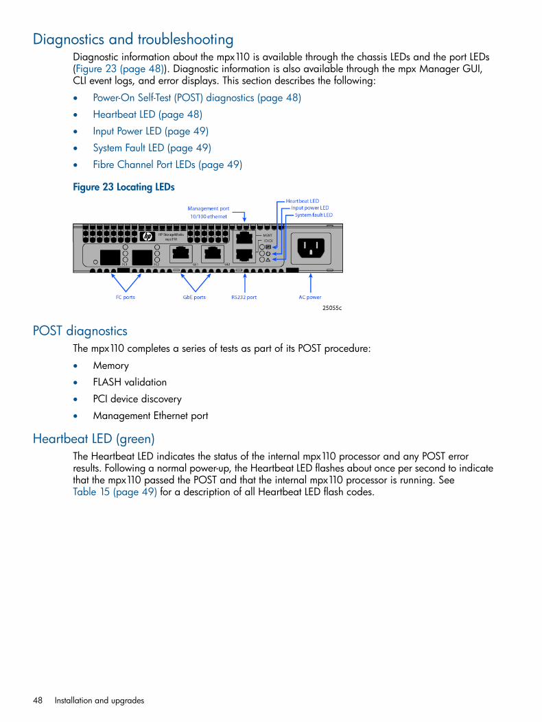
Diagnostics and troubleshootingDiagnostic information about the mpx110 is available through the chassis LEDs and the port LEDs(Figure 23 (page 48)). Diagnostic information is also available through the mpx Manager GUI,CLI event logs, and error displays. This section describes the following:
• Power-On Self-Test (POST) diagnostics (page 48)
• Heartbeat LED (page 48)
• Input Power LED (page 49)
• System Fault LED (page 49)
• Fibre Channel Port LEDs (page 49)
Figure 23 Locating LEDs
POST diagnosticsThe mpx110 completes a series of tests as part of its POST procedure:
• Memory
• FLASH validation
• PCI device discovery
• Management Ethernet port
Heartbeat LED (green)The Heartbeat LED indicates the status of the internal mpx110 processor and any POST errorresults. Following a normal power-up, the Heartbeat LED flashes about once per second to indicatethat the mpx110 passed the POST and that the internal mpx110 processor is running. SeeTable 15 (page 49) for a description of all Heartbeat LED flash codes.
48 Installation and upgrades
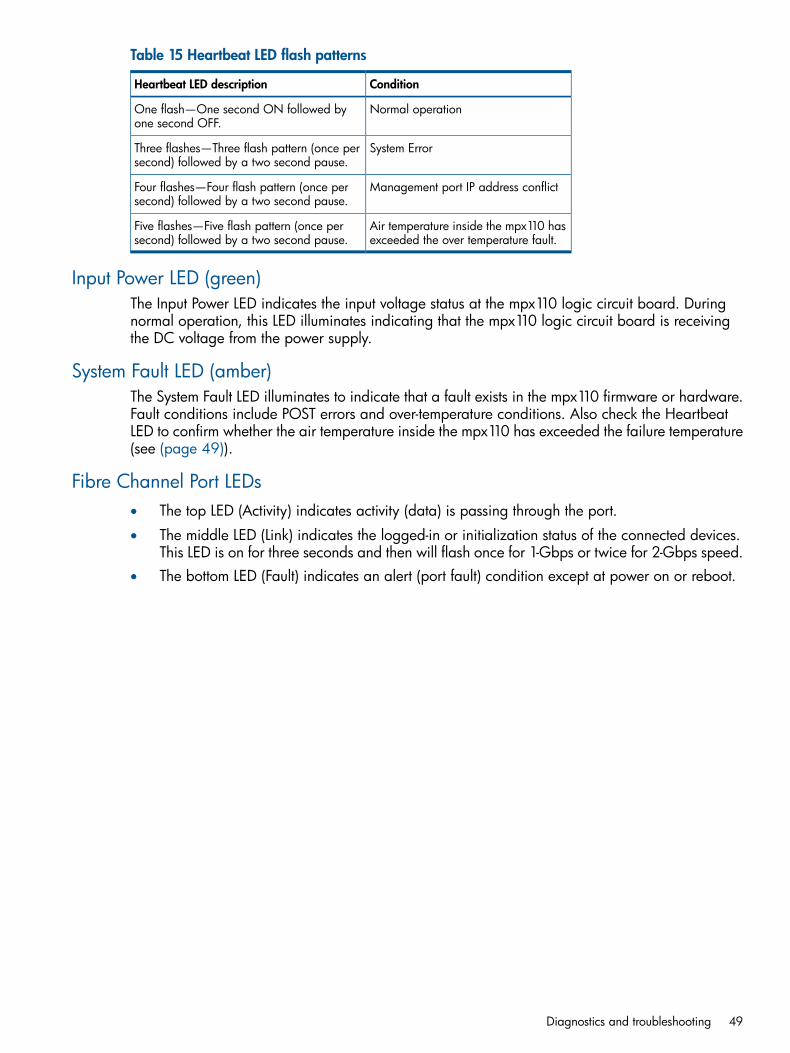
Table 15 Heartbeat LED flash patterns
ConditionHeartbeat LED description
Normal operationOne flash—One second ON followed byone second OFF.
System ErrorThree flashes—Three flash pattern (once persecond) followed by a two second pause.
Management port IP address conflictFour flashes—Four flash pattern (once persecond) followed by a two second pause.
Air temperature inside the mpx110 hasexceeded the over temperature fault.
Five flashes—Five flash pattern (once persecond) followed by a two second pause.
Input Power LED (green)The Input Power LED indicates the input voltage status at the mpx110 logic circuit board. Duringnormal operation, this LED illuminates indicating that the mpx110 logic circuit board is receivingthe DC voltage from the power supply.
System Fault LED (amber)The System Fault LED illuminates to indicate that a fault exists in the mpx110 firmware or hardware.Fault conditions include POST errors and over-temperature conditions. Also check the HeartbeatLED to confirm whether the air temperature inside the mpx110 has exceeded the failure temperature(see (page 49)).
Fibre Channel Port LEDs• The top LED (Activity) indicates activity (data) is passing through the port.
• The middle LED (Link) indicates the logged-in or initialization status of the connected devices.This LED is on for three seconds and then will flash once for 1-Gbps or twice for 2-Gbps speed.
• The bottom LED (Fault) indicates an alert (port fault) condition except at power on or reboot.
Diagnostics and troubleshooting 49
4 Using the HP mpx Manager utilityThis chapter describes the HP mpx Manager, the software tool used to manage the mpx110.
OverviewThe HP mpx Manager enables you to manage the mpx110 gateway, and to monitor, configure,and modify information from a workstation. The mpx Manager GUI consists of a menu bar, toolbar, system tree, information/data status windows, and tabs (see Figure 24 (page 50) andTable 16 (page 51)).
Figure 24 mpx Manager main window
50 Using the HP mpx Manager utility
Table 16 GUI main window sections
DescriptionItem
Provides access to system functions and wizards.Menu bar
Provides quick access to the common application functions—Connect,View Logs, and Refresh.
Tool bar
Determines what is displayed in the window.Tabs
To open, right-click the mouse. This menu provides a short cut to actionsfor the item that was right-clicked in the GUI.
Action menu
Located on the left side of the display, shows the connected systems andtheir components. Click an entry handle or double-click the entry to expandor collapse a system tree entry.
System tree
Shows the corresponding information, configuration, or status for theselected tab.
Information/data status window
Overview 51

Menu barFigure 25 (page 52) shows the menu bar options described in this section.
Figure 25 Menu bar
File menuThe File menu includes the following options, as shown in Figure 26 (page 52):
• Save FRU—Saves the gateway’s configuration and persistent data to a file
• Restore FRU—Restores the gateway’s configuration and persistent data from a file
• Exit—Exits the mpx Manager GUI
Figure 26 File menu
View menuThe View menu displays the View Logs option (Figure 27 (page 52)), which opens the system logs.
Figure 27 View menu
52 Using the HP mpx Manager utility
Settings menuThe Settings menu includes the Broadcast option, which opens the Broadcast Settings option, asshown in Figure 28 (page 53).
Figure 28 Settings menu
Wizards menuThe Wizards menu includes the following options, as shown in Figure 29 (page 53):
• FW Update Wizard—Launches the Firmware Update Wizard, which enables you to updatethe mpx110 gateway’s firmware image. The firmware image is selected from a menu thatenables browsing.
• FCIP Route Add—Launches the FCIP Route Add wizard, which enables you to select theresources used for the route, the IP address of the remote FCIP peer, IP parameters, VLANsupport, compression, and bandwidth limit.
• FCIP Route Remove—Launches the FCIP Route Remove wizard, which enables you to removean existing FCIP Route, freeing the resources (FC and GE ports) used by the route.
NOTE: Figure 29 (page 53) shows wizard menus not supported by the gateway at the time ofthis document's release. Only wizards applicable to the mpx110 are described.
Figure 29 Sample Wizards menu
Overview 53
Help menuThe Help menu (Figure 30 (page 54)) includes the following options:
• Set Browser Location—Specifies the browser that is launched when you view the online helpfor the mpx Manager GUI
• Browse Contents—Launches the online help
• About—Displays the application version information
Figure 30 Help menu
Tool barThe tool bar (Figure 31 (page 54)) consists of a row of graphical buttons that enable you to performcommon functions such as connect to an mpx110 gateway, view log files, and refresh the currentdisplay. The tool bar can be relocated in the display by clicking and dragging the handle at theleft edge of the tool bar.
• Connect—Adds an mpx110 gateway to the system tree view
• Logs—Opens a window to display the system log data
• Refresh—Updates the display with current information
Figure 31 Tool bar
Action menuThe Action menu (Figure 32 (page 55)), which is displayed by right-clicking the mouse, providesshortcuts to actions available elsewhere in the GUI.
NOTE: Figure 32 (page 55) shows features not supported at the time of this document's release.Only Menu features applicable to the mpx110 are described.
The Action menu options are as follows:
• Connect—Adds an mpx110 gateway to the system tree view
• Refresh—Updates the display with current information
• Disconnect—Disconnects from an mpx110 gateway, removing it from the system tree
• Reboot—Reboots the mpx110 gateway
54 Using the HP mpx Manager utility
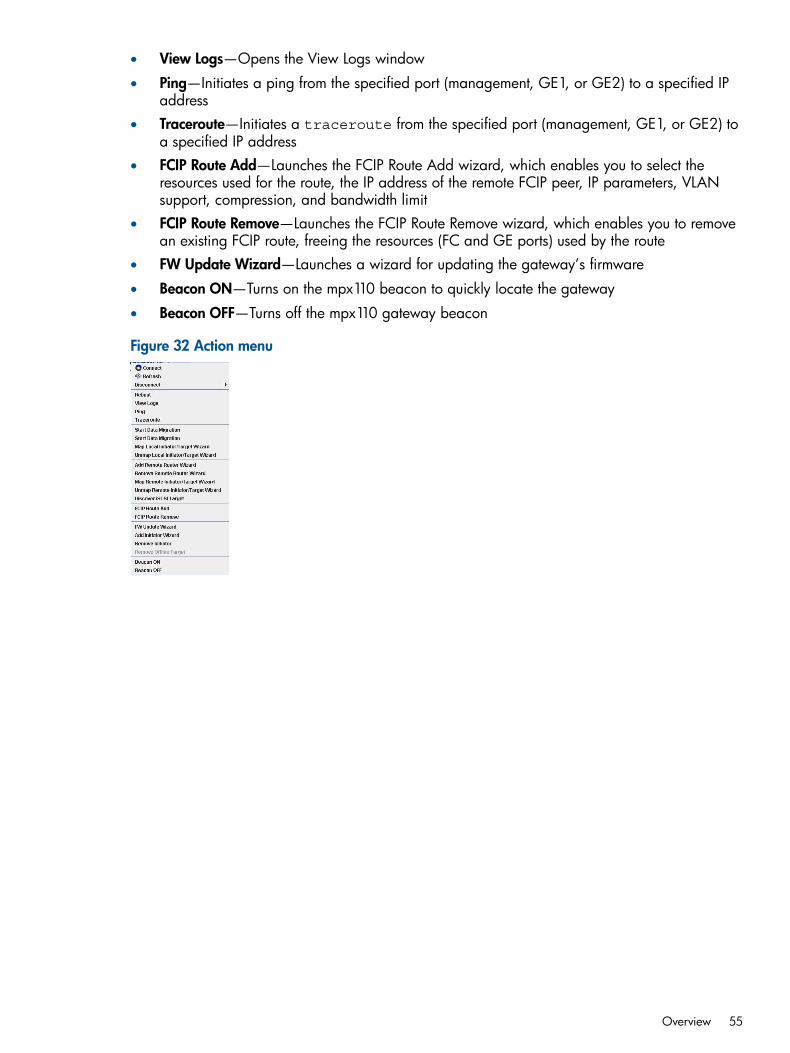
• View Logs—Opens the View Logs window
• Ping—Initiates a ping from the specified port (management, GE1, or GE2) to a specified IPaddress
• Traceroute—Initiates a traceroute from the specified port (management, GE1, or GE2) toa specified IP address
• FCIP Route Add—Launches the FCIP Route Add wizard, which enables you to select theresources used for the route, the IP address of the remote FCIP peer, IP parameters, VLANsupport, compression, and bandwidth limit
• FCIP Route Remove—Launches the FCIP Route Remove wizard, which enables you to removean existing FCIP route, freeing the resources (FC and GE ports) used by the route
• FW Update Wizard—Launches a wizard for updating the gateway’s firmware
• Beacon ON—Turns on the mpx110 beacon to quickly locate the gateway
• Beacon OFF—Turns off the mpx110 gateway beacon
Figure 32 Action menu
Overview 55
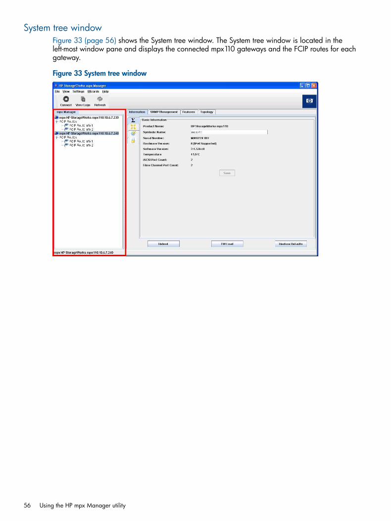
System tree windowFigure 33 (page 56) shows the System tree window. The System tree window is located in theleft-most window pane and displays the connected mpx110 gateways and the FCIP routes for eachgateway.
Figure 33 System tree window
56 Using the HP mpx Manager utility
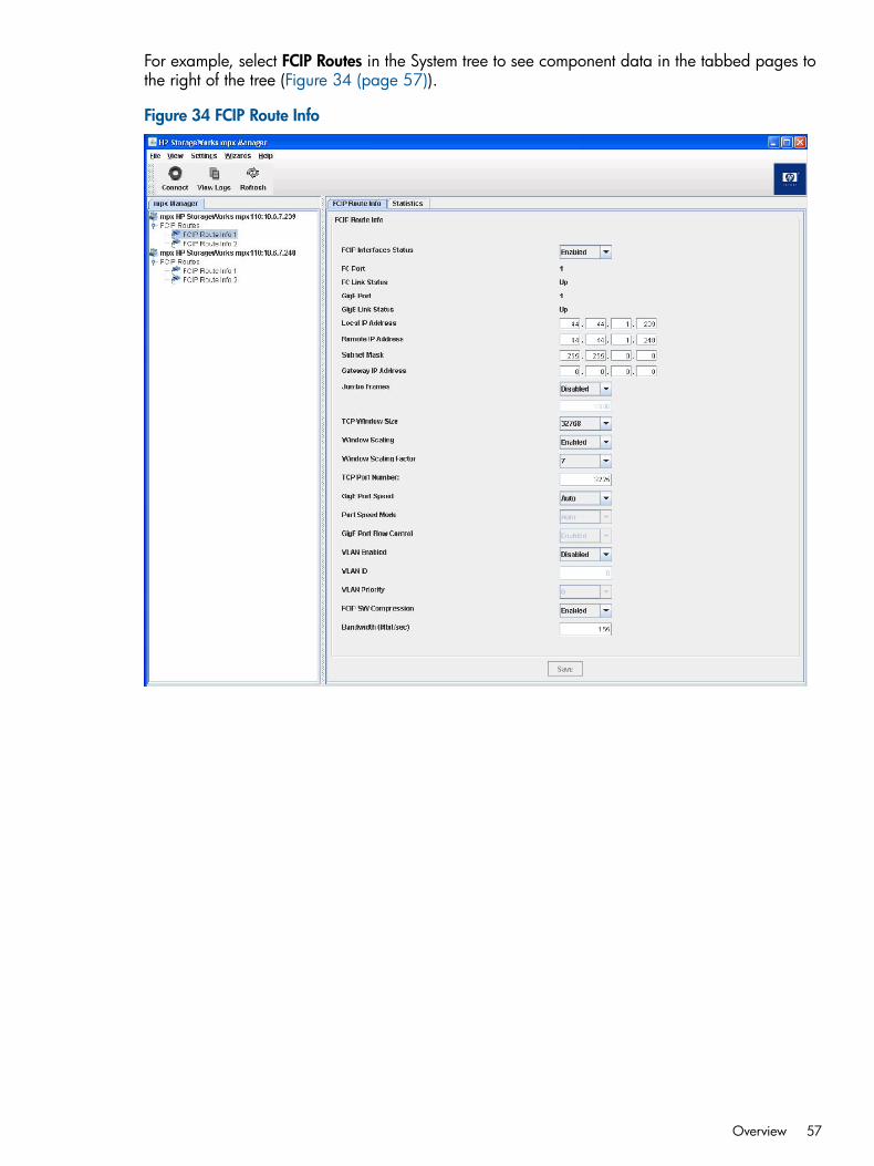
For example, select FCIP Routes in the System tree to see component data in the tabbed pages tothe right of the tree (Figure 34 (page 57)).
Figure 34 FCIP Route Info
Overview 57

mpx110 gatewayThe top of the Information/Data/Status window displays the gateway system configuration andstatus. It contains the following tabs:
• Page 58
• Page 62
• SNMP Management tab (page 63)
Information tabThe Information tab consists of four subpages:
• Basic Information—Use to display basic product information.
Click the icon to access the following settings (Figure 36 (page 60)):
◦ Product Name—HP model mpx110
◦ Symbolic Name—A symbolic name you can create for the gateway
◦ Serial Number—Serial number of the gateway
◦ Hardware Version—The gateway hardware version number
◦ Software Version—The gateway software version number
◦ Temperature—The current temperature reading, in degrees Celsius (C)
◦ iSCSI Port Count—The number of iSCSI ports (two)
◦ Fibre Channel Port Count—The number of FC ports (two)
58 Using the HP mpx Manager utility
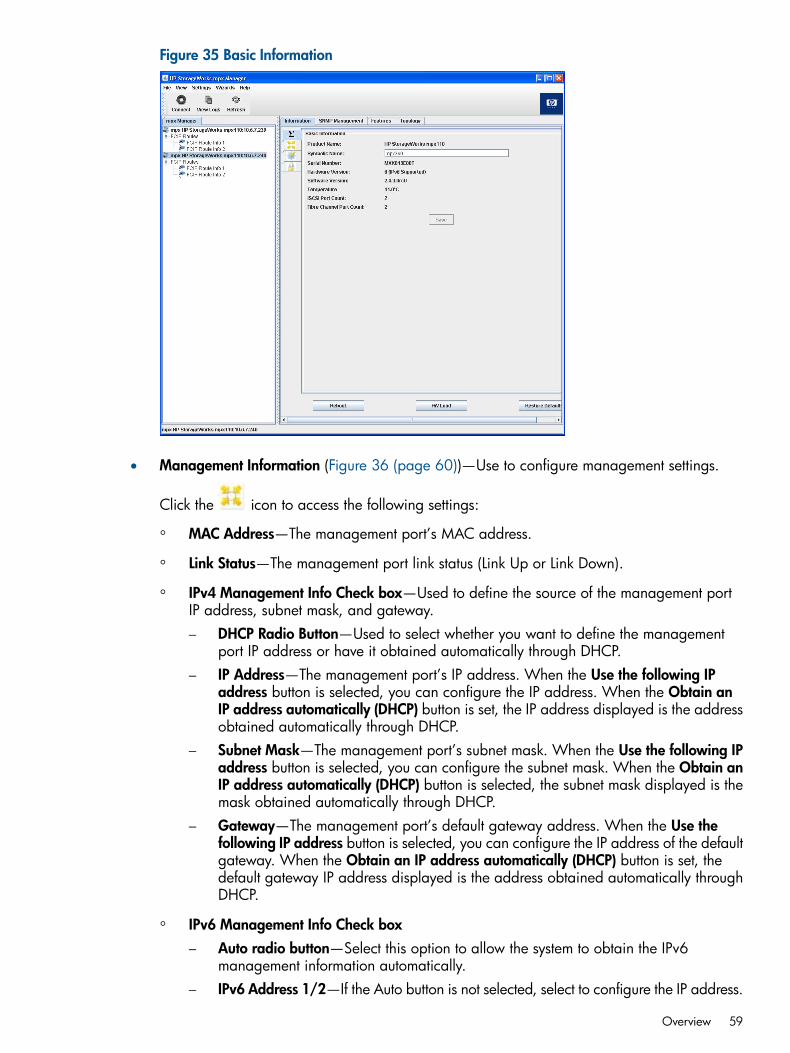
Figure 35 Basic Information
• Management Information (Figure 36 (page 60))—Use to configure management settings.
Click the icon to access the following settings:
◦ MAC Address—The management port’s MAC address.
◦ Link Status—The management port link status (Link Up or Link Down).
◦ IPv4 Management Info Check box—Used to define the source of the management portIP address, subnet mask, and gateway.– DHCP Radio Button—Used to select whether you want to define the management
port IP address or have it obtained automatically through DHCP.– IP Address—The management port’s IP address. When the Use the following IP
address button is selected, you can configure the IP address. When the Obtain anIP address automatically (DHCP) button is set, the IP address displayed is the addressobtained automatically through DHCP.
– Subnet Mask—The management port’s subnet mask. When the Use the following IPaddress button is selected, you can configure the subnet mask. When the Obtain anIP address automatically (DHCP) button is selected, the subnet mask displayed is themask obtained automatically through DHCP.
– Gateway—The management port’s default gateway address. When the Use thefollowing IP address button is selected, you can configure the IP address of the defaultgateway. When the Obtain an IP address automatically (DHCP) button is set, thedefault gateway IP address displayed is the address obtained automatically throughDHCP.
◦ IPv6 Management Info Check boxAuto radio button—Select this option to allow the system to obtain the IPv6management information automatically.
–
– IPv6 Address 1/2—If the Auto button is not selected, select to configure the IP address.
Overview 59
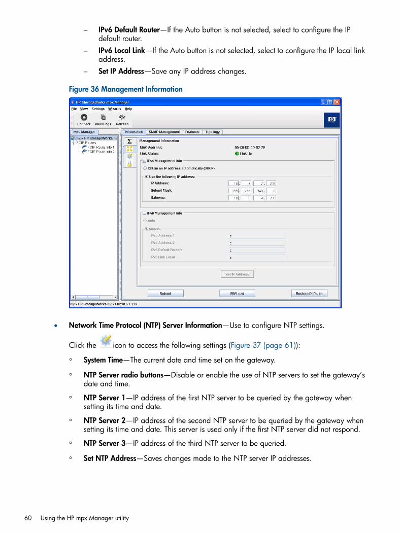
– IPv6 Default Router—If the Auto button is not selected, select to configure the IPdefault router.
– IPv6 Local Link—If the Auto button is not selected, select to configure the IP local linkaddress.
– Set IP Address—Save any IP address changes.
Figure 36 Management Information
• Network Time Protocol (NTP) Server Information—Use to configure NTP settings.
Click the icon to access the following settings (Figure 37 (page 61)):
◦ System Time—The current date and time set on the gateway.
◦ NTP Server radio buttons—Disable or enable the use of NTP servers to set the gateway’sdate and time.
◦ NTP Server 1—IP address of the first NTP server to be queried by the gateway whensetting its time and date.
◦ NTP Server 2—IP address of the second NTP server to be queried by the gateway whensetting its time and date. This server is used only if the first NTP server did not respond.
◦ NTP Server 3—IP address of the third NTP server to be queried.
◦ Set NTP Address—Saves changes made to the NTP server IP addresses.
60 Using the HP mpx Manager utility

Figure 37 NTP Server Information
Overview 61

Security tabThe Security tab (Figure 38 (page 62)) enables you to set the gateway’s password.
Click the icon to access the following settings:
• Current Password—The current password must be supplied before it can be changed.
• New Password—Enter the new gateway password.
• Verify New Password—Enter the same content as in the New Password field, to verify that itwas typed correctly.
• Apply—Save the password changes.
• Clear Fields—Clear the Current Password, New Password, and Verify Password fields.
Figure 38 Security tab
62 Using the HP mpx Manager utility
SNMP Management tabThe SNMP Management tab (Figure 39 (page 64)) consists of two sections: SNMP Configurationand SNMP Trap Receivers. The Save button saves any SNMP management changes. For moreinformation, see Simple Network Management Protocol (page 132).SNMP Management tab options include:
• SNMP Configuration
System OID—The system object identifier.◦◦ System Description—Text that identifies the gateway.
◦ Read Community—A password that authorizes an SNMP management server to readinformation from the router. This is a write-only field. The value on the gateway and theSNMP management server must be the same. The Read Community password can be upto 32 characters and cannot include a #, semicolon (;), and comma (,). The default ispublic.
◦ Trap Community—A password that authorizes an SNMP management server to receivetraps. This is a write-only field. The value on the gateway and the SNMP managementserver must be the same. The Trap Community password can be up to 32 characters andcannot include a number sign (#), semicolon (;), and comma (,). The default is public.
◦ System Location—Specifies the name of the gateway location. The name can be up to64 characters and cannot include a number sign (#), semicolon (;), and comma (,).
◦ System Contact—Specifies the name of the person to be contacted to respond to trapevents. The name can be up to 64 characters excluding the number sign (#), semicolon(;), and comma (,).
◦ Authentication Traps—Enables or disables the generation of authentication traps inresponse to authentication failures.
• SNMP Trap Receivers
Enabled—A check box to enable the trap receiver specified by the IP address, trap port,and trap version.
◦
◦ IP Address—Specifies the IP address to which the SNMP traps are sent. A maximum ofeight trap addresses are supported.
◦ Trap Port—Specifies the port number on which the trap is sent. The default is 162.
◦ Trap Version—Specifies the SNMP version (1 or 2) with which to format traps.
Overview 63
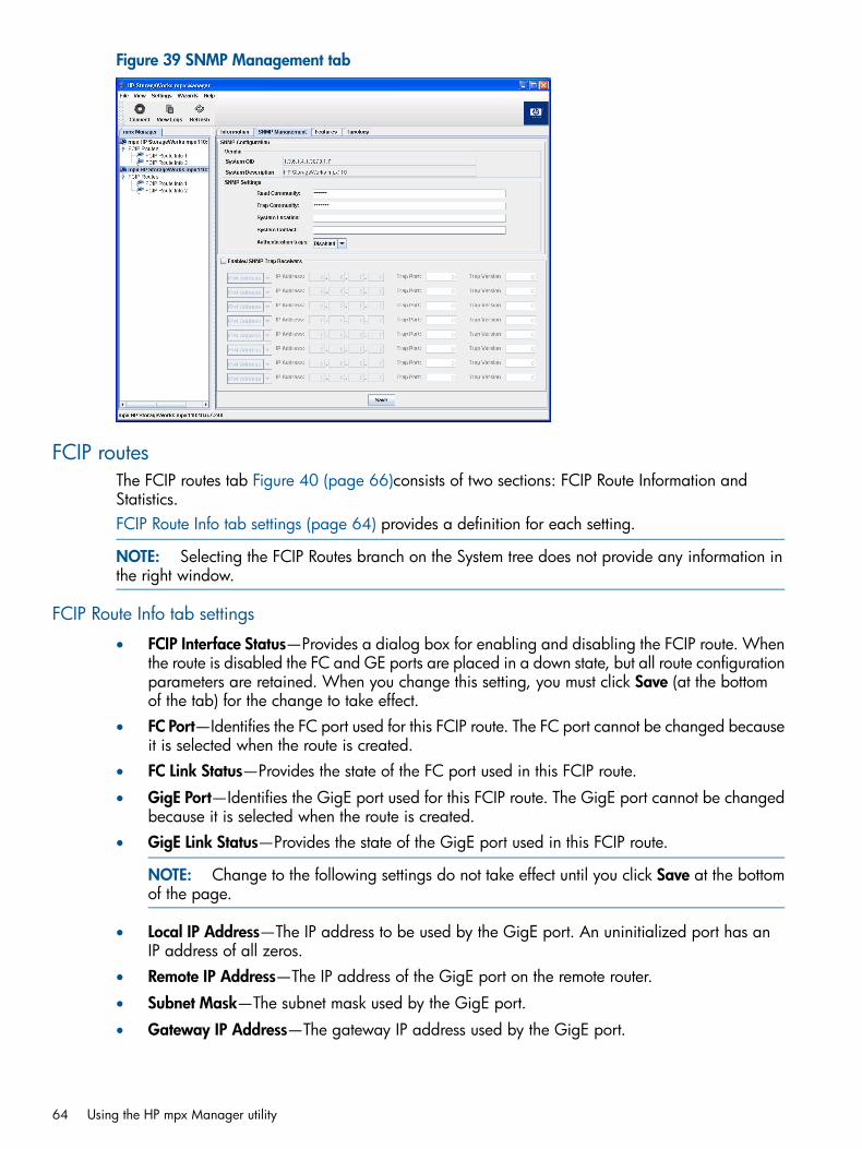
Figure 39 SNMP Management tab
FCIP routesThe FCIP routes tab Figure 40 (page 66)consists of two sections: FCIP Route Information andStatistics.FCIP Route Info tab settings (page 64) provides a definition for each setting.
NOTE: Selecting the FCIP Routes branch on the System tree does not provide any information inthe right window.
FCIP Route Info tab settings
• FCIP Interface Status—Provides a dialog box for enabling and disabling the FCIP route. Whenthe route is disabled the FC and GE ports are placed in a down state, but all route configurationparameters are retained. When you change this setting, you must click Save (at the bottomof the tab) for the change to take effect.
• FC Port—Identifies the FC port used for this FCIP route. The FC port cannot be changed becauseit is selected when the route is created.
• FC Link Status—Provides the state of the FC port used in this FCIP route.
• GigE Port—Identifies the GigE port used for this FCIP route. The GigE port cannot be changedbecause it is selected when the route is created.
• GigE Link Status—Provides the state of the GigE port used in this FCIP route.
NOTE: Change to the following settings do not take effect until you click Save at the bottomof the page.
• Local IP Address—The IP address to be used by the GigE port. An uninitialized port has anIP address of all zeros.
• Remote IP Address—The IP address of the GigE port on the remote router.
• Subnet Mask—The subnet mask used by the GigE port.
• Gateway IP Address—The gateway IP address used by the GigE port.
64 Using the HP mpx Manager utility
• Jumbo Frames—Provides a dialog box for enabling and disabling Jumbo IP frames. Whendisabled, the MTU is 1,500 bytes; when enabled, the maximum MTU is 9,000 bytes. Whenother is selected, the MTU size can be set between 1,000 and 9,000 bytes.
• TCP Window Size—Contains a dialog box that provides three options for TCP window size:8,192, 16, 384, and 32,768 bytes. The default is 32,768.
• Window Scaling—Contains a dialog box that provides for enabling and disabling TCP windowscaling. The default is Disabled. When enabled, the Window Scaling Factor is used.
• Window Scaling Factor—Contains a dialog box that provides six options for TCP windowscaling: 0, 1, 2, 3, 4, 5, 6, and 7.
• TCP Port Number—Provides a dialog box that enables the user to define the destination TCPport number used by the FCIP route. This port number must be the same on both routersparticipating in the FCIP route (local and remote routers must be using same port number).The default port number used by FCIP is 3225.
• GigE Port Speed—Provides a dialog box that contains four options for the GigE port speed:Auto, 10, 100, and 1000: The port speed rate is Auto.
• Port Speed Mode—Provides a dialog box that contains three options for the link rate mode:Auto, half duplex, and full duplex. This dialog box is available only when the GigE port speedis set to something other than Auto.
• GigE Port Flow Control—Provides a dialog box for enabling and disabling GigE port flowcontrol. The default is Enabled. This dialog box is available only when the GigE port speedis set to something other than Auto.
• VLAN Enabled—Provides a dialog box for enabling and disabling VLAN support. The defaultis Disabled.
• VLAN ID—Provides a dialog box that enables the user to define the VLAN ID. This dialog boxis available only when VLAN is enabled. The VLAN ID must be the same on both gatewaysparticipating in the FCIP route (local and remote gateways must be using same VLAN ID) andthe Ethernet switches.
• VLAN Priority—Provides a dialog box that contains eight options for the VLAN priority: 0through 7. This dialog box is available only when VLAN is Enabled.
• FCIP SW Compression—Provides a dialog box for enabling and disabling FCIP compression.The default is Disabled.
• Bandwidth (Mbit/sec)—Provides a dialog box that enables the user to define the maximumbandwidth (in Mb/s) used by the GigE port during transmits. The range of values supportedis 1 to 1,000 Mb/s. This setting enables the user to limit the bandwidth used by each FCIProute so as not to consume all the available link bandwidth. For example, if the slowest linkin the WAN being used is a DS-3 link, then the maximum available bandwidth is 45 Mb/s.To limit the FCIP route to 33% of the overall link bandwidth, set the bandwidth to 15 Mb/s(see Bandwidth per route (page 25)).HP P9000 and P6000 Continuous Access replication solution requires dedicated bandwidthfor the intersite link. If other applications share the intersite link, some method of QoS mustbe used to ensure that the replication application has uncontested access to the allocatedbandwidth.
Overview 65

Figure 40 FCIP Route Info
66 Using the HP mpx Manager utility
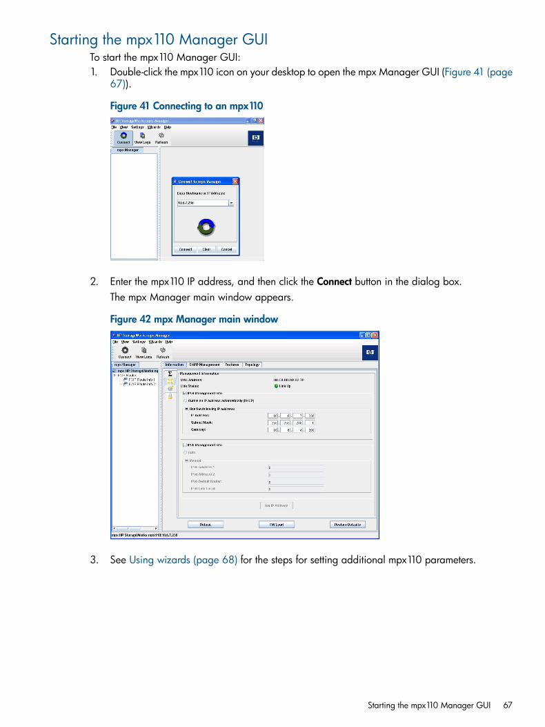
Starting the mpx110 Manager GUITo start the mpx110 Manager GUI:1. Double-click the mpx110 icon on your desktop to open the mpx Manager GUI (Figure 41 (page
67)).
Figure 41 Connecting to an mpx110
2. Enter the mpx110 IP address, and then click the Connect button in the dialog box.The mpx Manager main window appears.
Figure 42 mpx Manager main window
3. See Using wizards (page 68) for the steps for setting additional mpx110 parameters.
Starting the mpx110 Manager GUI 67
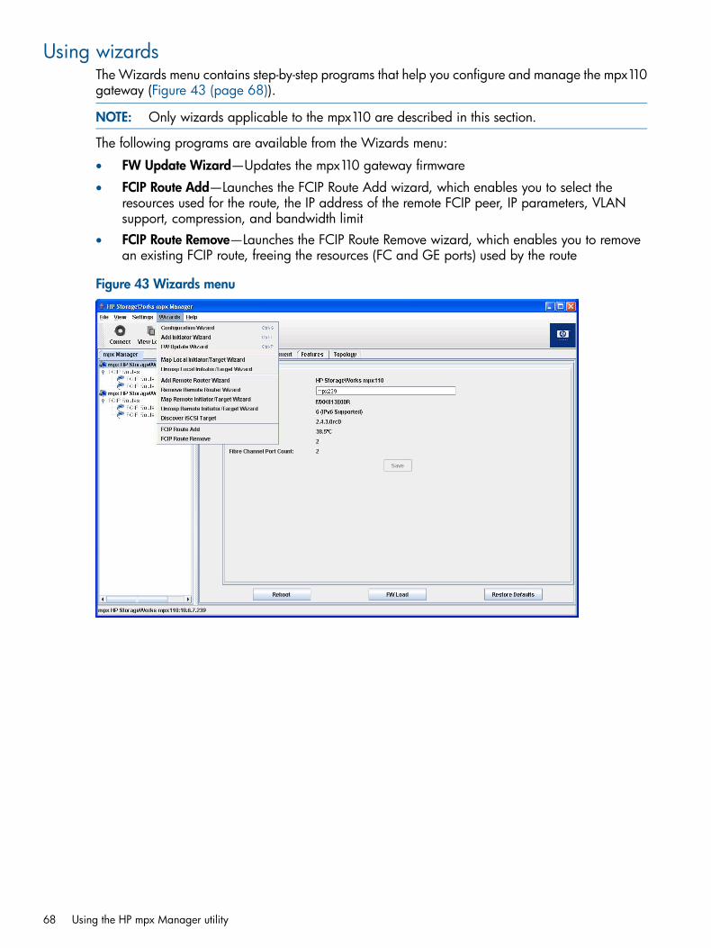
Using wizardsThe Wizards menu contains step-by-step programs that help you configure and manage the mpx110gateway (Figure 43 (page 68)).
NOTE: Only wizards applicable to the mpx110 are described in this section.
The following programs are available from the Wizards menu:
• FW Update Wizard—Updates the mpx110 gateway firmware
• FCIP Route Add—Launches the FCIP Route Add wizard, which enables you to select theresources used for the route, the IP address of the remote FCIP peer, IP parameters, VLANsupport, compression, and bandwidth limit
• FCIP Route Remove—Launches the FCIP Route Remove wizard, which enables you to removean existing FCIP route, freeing the resources (FC and GE ports) used by the route
Figure 43 Wizards menu
68 Using the HP mpx Manager utility
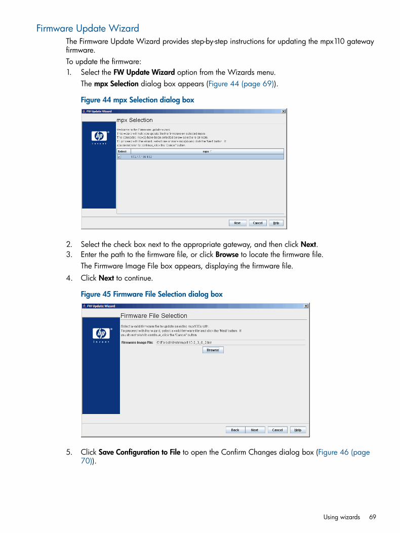
Firmware Update WizardThe Firmware Update Wizard provides step-by-step instructions for updating the mpx110 gatewayfirmware.To update the firmware:1. Select the FW Update Wizard option from the Wizards menu.
The mpx Selection dialog box appears (Figure 44 (page 69)).
Figure 44 mpx Selection dialog box
2. Select the check box next to the appropriate gateway, and then click Next.3. Enter the path to the firmware file, or click Browse to locate the firmware file.
The Firmware Image File box appears, displaying the firmware file.4. Click Next to continue.
Figure 45 Firmware File Selection dialog box
5. Click Save Configuration to File to open the Confirm Changes dialog box (Figure 46 (page70)).
Using wizards 69
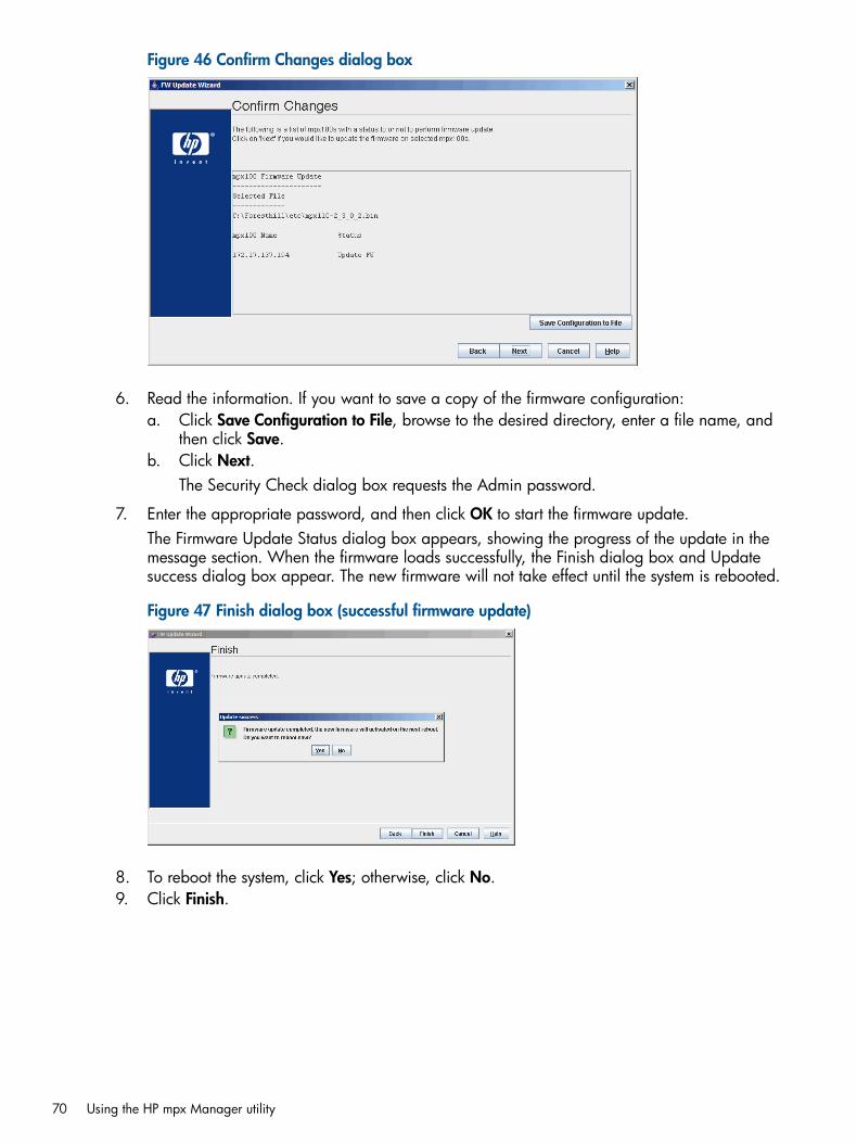
Figure 46 Confirm Changes dialog box
6. Read the information. If you want to save a copy of the firmware configuration:a. Click Save Configuration to File, browse to the desired directory, enter a file name, and
then click Save.b. Click Next.
The Security Check dialog box requests the Admin password.
7. Enter the appropriate password, and then click OK to start the firmware update.The Firmware Update Status dialog box appears, showing the progress of the update in themessage section. When the firmware loads successfully, the Finish dialog box and Updatesuccess dialog box appear. The new firmware will not take effect until the system is rebooted.
Figure 47 Finish dialog box (successful firmware update)
8. To reboot the system, click Yes; otherwise, click No.9. Click Finish.
70 Using the HP mpx Manager utility
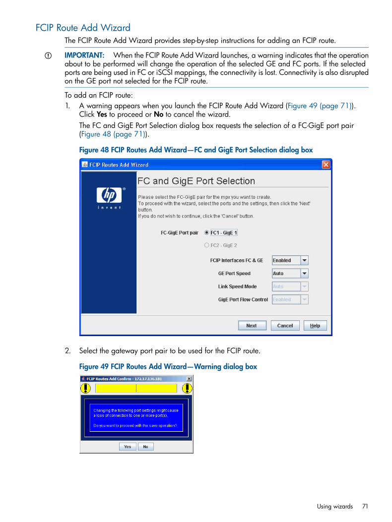
FCIP Route Add WizardThe FCIP Route Add Wizard provides step-by-step instructions for adding an FCIP route.
IMPORTANT: When the FCIP Route AddWizard launches, a warning indicates that the operationabout to be performed will change the operation of the selected GE and FC ports. If the selectedports are being used in FC or iSCSI mappings, the connectivity is lost. Connectivity is also disruptedon the GE port not selected for the FCIP route.
To add an FCIP route:1. A warning appears when you launch the FCIP Route Add Wizard (Figure 49 (page 71)).
Click Yes to proceed or No to cancel the wizard.The FC and GigE Port Selection dialog box requests the selection of a FC-GigE port pair(Figure 48 (page 71)).
Figure 48 FCIP Routes Add Wizard—FC and GigE Port Selection dialog box
2. Select the gateway port pair to be used for the FCIP route.
Figure 49 FCIP Routes Add Wizard—Warning dialog box
Using wizards 71

3. (Optional) Configure the following port route/parameters:• FCIP Interfaces FC & GE—Provides a dialog box for enabling and disabling the FCIP
route. When the route is disabled the FC and GE ports are placed in a down state: allroute configuration parameters are retained.
• GigE Port Programmed Port Speed—Provides a dialog box that contains four options forthe GigE port speed: Auto, 10, 100, and 1000. The default port speed is Auto.
• Port Speed Mode—Provides a dialog box that contains three options for the port speedmode: Auto, Half duplex, and Full duplex. This dialog box is available only when theGigE port speed is set to something other than Auto.
• GigE Port Flow Control—Provides a dialog box for enabling and disabling GigE portflow control. The default is enabled. This dialog box is available only when the GigE portspeed is set to something other than Auto.
4. After selecting a port pair and setting GE port parameters, click Next to continue or Cancelto exit the wizard.
5. Enter the IP addresses (Figure 50 (page 72)).
Figure 50 FCIP Routes Add Wizard—Local and Remote IP Address dialog box
6. Click Next to continue. Otherwise, click Cancel to exit the wizard.7. Select either the IPv4 Address or IPv6 Address radio button.
IPv4 parameters include:
• Local IP Address—The IP address to be used by the GigE port. An uninitialized port hasan IP address of all zeros.
• Subnet Mask—The subnet mask used by the GigE port.
• Gateway IP Address—The gateway IP address used by the GigE port.
• Remote IP Address—The IP address of the GigE port on the remote gateway.
72 Using the HP mpx Manager utility
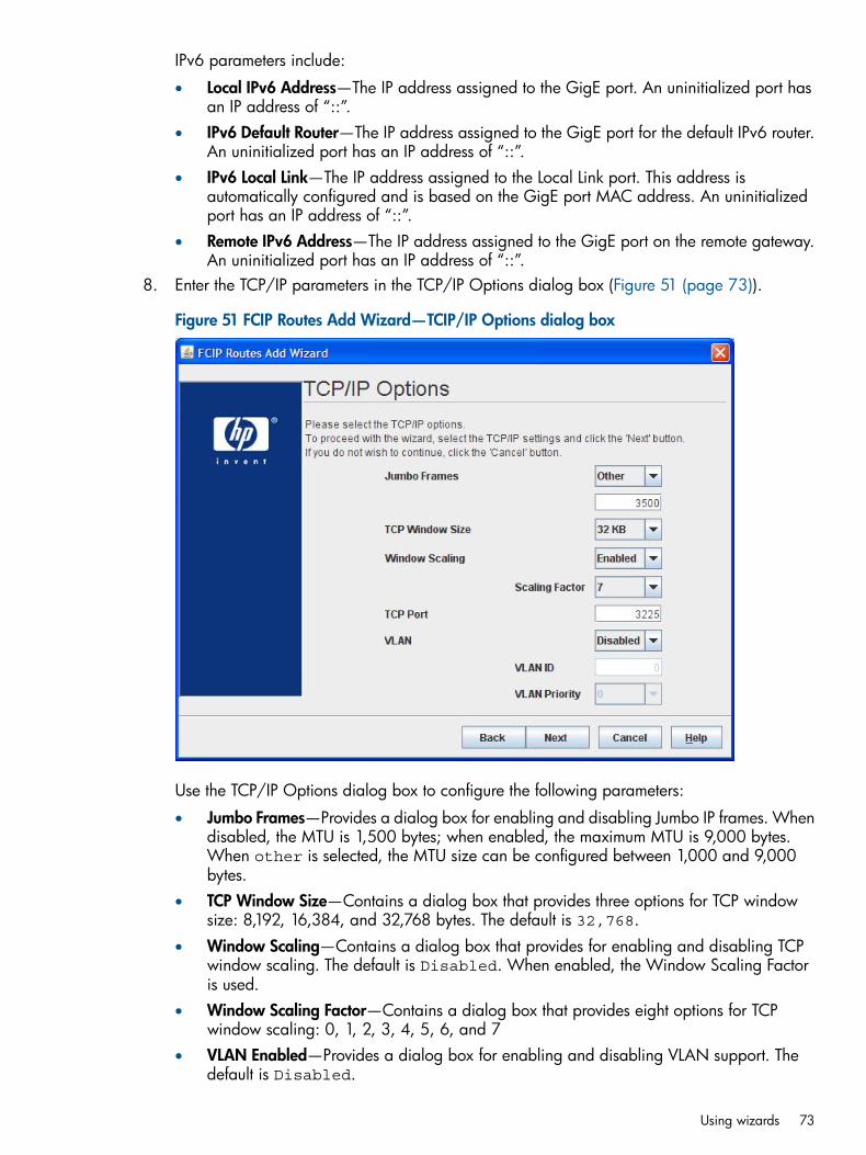
IPv6 parameters include:
• Local IPv6 Address—The IP address assigned to the GigE port. An uninitialized port hasan IP address of “::”.
• IPv6 Default Router—The IP address assigned to the GigE port for the default IPv6 router.An uninitialized port has an IP address of “::”.
• IPv6 Local Link—The IP address assigned to the Local Link port. This address isautomatically configured and is based on the GigE port MAC address. An uninitializedport has an IP address of “::”.
• Remote IPv6 Address—The IP address assigned to the GigE port on the remote gateway.An uninitialized port has an IP address of “::”.
8. Enter the TCP/IP parameters in the TCP/IP Options dialog box (Figure 51 (page 73)).
Figure 51 FCIP Routes Add Wizard—TCIP/IP Options dialog box
Use the TCP/IP Options dialog box to configure the following parameters:
• Jumbo Frames—Provides a dialog box for enabling and disabling Jumbo IP frames. Whendisabled, the MTU is 1,500 bytes; when enabled, the maximum MTU is 9,000 bytes.When other is selected, the MTU size can be configured between 1,000 and 9,000bytes.
• TCP Window Size—Contains a dialog box that provides three options for TCP windowsize: 8,192, 16,384, and 32,768 bytes. The default is 32,768.
• Window Scaling—Contains a dialog box that provides for enabling and disabling TCPwindow scaling. The default is Disabled. When enabled, the Window Scaling Factoris used.
• Window Scaling Factor—Contains a dialog box that provides eight options for TCPwindow scaling: 0, 1, 2, 3, 4, 5, 6, and 7
• VLAN Enabled—Provides a dialog box for enabling and disabling VLAN support. Thedefault is Disabled.
Using wizards 73
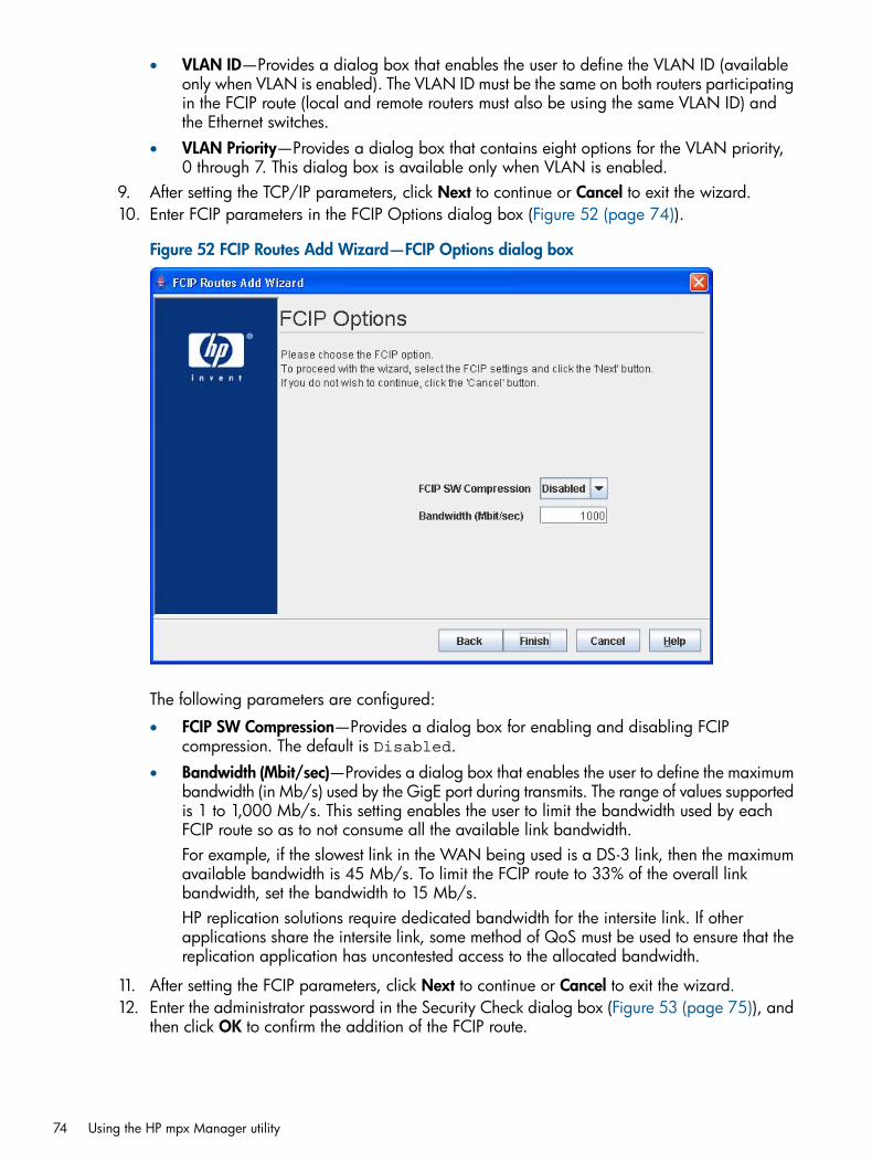
• VLAN ID—Provides a dialog box that enables the user to define the VLAN ID (availableonly when VLAN is enabled). The VLAN ID must be the same on both routers participatingin the FCIP route (local and remote routers must also be using the same VLAN ID) andthe Ethernet switches.
• VLAN Priority—Provides a dialog box that contains eight options for the VLAN priority,0 through 7. This dialog box is available only when VLAN is enabled.
9. After setting the TCP/IP parameters, click Next to continue or Cancel to exit the wizard.10. Enter FCIP parameters in the FCIP Options dialog box (Figure 52 (page 74)).
Figure 52 FCIP Routes Add Wizard—FCIP Options dialog box
The following parameters are configured:
• FCIP SW Compression—Provides a dialog box for enabling and disabling FCIPcompression. The default is Disabled.
• Bandwidth (Mbit/sec)—Provides a dialog box that enables the user to define the maximumbandwidth (in Mb/s) used by the GigE port during transmits. The range of values supportedis 1 to 1,000 Mb/s. This setting enables the user to limit the bandwidth used by eachFCIP route so as to not consume all the available link bandwidth.For example, if the slowest link in the WAN being used is a DS-3 link, then the maximumavailable bandwidth is 45 Mb/s. To limit the FCIP route to 33% of the overall linkbandwidth, set the bandwidth to 15 Mb/s.HP replication solutions require dedicated bandwidth for the intersite link. If otherapplications share the intersite link, some method of QoS must be used to ensure that thereplication application has uncontested access to the allocated bandwidth.
11. After setting the FCIP parameters, click Next to continue or Cancel to exit the wizard.12. Enter the administrator password in the Security Check dialog box (Figure 53 (page 75)), and
then click OK to confirm the addition of the FCIP route.
74 Using the HP mpx Manager utility
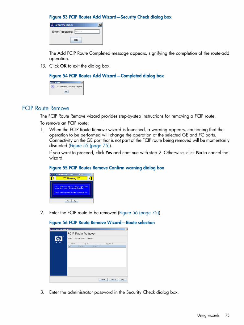
Figure 53 FCIP Routes Add Wizard—Security Check dialog box
The Add FCIP Route Completed message appears, signifying the completion of the route-addoperation.
13. Click OK to exit the dialog box.
Figure 54 FCIP Routes Add Wizard—Completed dialog box
FCIP Route RemoveThe FCIP Route Remove wizard provides step-by-step instructions for removing a FCIP route.To remove an FCIP route:1. When the FCIP Route Remove wizard is launched, a warning appears, cautioning that the
operation to be performed will change the operation of the selected GE and FC ports.Connectivity on the GE port that is not part of the FCIP route being removed will be momentarilydisrupted (Figure 55 (page 75)).If you want to proceed, click Yes and continue with step 2. Otherwise, click No to cancel thewizard.
Figure 55 FCIP Routes Remove Confirm warning dialog box
2. Enter the FCIP route to be removed (Figure 56 (page 75)).
Figure 56 FCIP Route Remove Wizard—Route selection
3. Enter the administrator password in the Security Check dialog box.
Using wizards 75

4. Click OK to confirm the removal of the FCIP route.The Remove FCIP Route Completed dialog box indicates the completion of the route removeoperation (Figure 57 (page 76)).
5. Click OK to exit the dialog box.
Figure 57 Remove FCIP Route Completed dialog
76 Using the HP mpx Manager utility
5 Support and other resourcesThis chapter describes the various resources available for operating and managing the mpx110.
Related documentationThe following documents provide related information:
• HP Command View EVA User Guide
• HP Continuous Access EVA Implementation Guide
• HP Command View EVA online help
• HP SAN Design Reference Guide
• HP 4400 Enterprise Virtual Array User Guide
• HP 6400/8400 Enterprise Virtual Array User Guide
• HP 4x00/6x00/8x00 Enterprise Virtual Array User Guide
• HP Enterprise Virtual Array 3000/5000 User Guide
• HP Replication Solutions Manager Installation Guide
• HP XP Continuous Access Journal User Guide
• HP Continuous Access XP User Guide
• HP XP24000 Continuous Access Journal Software User and Reference Guide
• HP XP24000 Disk Array Owner's Guide
• HP XP24000 Remote Web Console User Guide
• HP XP Remote Web Console User Guide for XP12000/XP10000
• HP LUN Configuration and Security Manager XP User Guide for the XP12000/XP10000
• HP XP Disk/Cache Partition User Guide
ConventionsThis section describes the conventions used in this document.
• Text conventions
• Alerts and symbols
Document conventions and symbolsTable 17 Document conventions
ElementConvention
Cross-reference links and email addressesBlue text: Table 17 (page 77)
website addressesBlue, underlined text: http://www.hp.com
Bold text • Keys that are pressed
• Text entered into a GUI element, such as a box
• GUI elements that are clicked or selected, such as menuand list items, buttons, tabs, and check boxes
Text emphasisItalic text
Related documentation 77
Table 17 Document conventions (continued)
ElementConvention
Monospace text • File and directory names
• System output
• Code
• Commands, their arguments, and argument values
Monospace, italic text • Code variables
• Command variables
Emphasized monospace textMonospace, bold text
WARNING! Indicates that failure to follow directions could result in bodily harm or death.
CAUTION: Indicates that failure to follow directions could result in damage to equipment or data.
IMPORTANT: Provides clarifying information or specific instructions.
NOTE: Provides additional information.
HP technical supportTelephone numbers for worldwide technical support are listed on the HP support website: http://www.hp.com/support/.Collect the following information before calling:
• Technical support registration number (if applicable)
• Product serial numbers
• Product model names and numbers
• Error messages
• Operating system type and revision level
• Detailed questionsFor continuous quality improvement, calls may be recorded or monitored.
Subscription serviceHP strongly recommends that customers register online using the Subscriber's choice website:http://www.hp.com/go/wwalerts.Subscribing to this service provides you with email updates on the latest product enhancements,newest driver versions, and firmware documentation updates as well as instant access to numerousother product resources.After subscribing, locate your products by selecting Business support and then Storage underProduct Category.
Other HP websitesFor additional information, see the following HP websites:
• http://www.hp.com
• http://www.hp.com/go/storage
78 Support and other resources

• http://www.docs.hp.com
• http://www.hp.com/go/sandesignguide
Other HP websites 79
A Command-line interfaceThis appendix includes information on using the command-line interface to manage the mpx110.
Logging on to the mpx110To log on to an mpx110 using Telnet, open a command-line window on the workstation, and thenenter the telnet command, followed by the mpx110 IP address:# telnet (ip-address)
A Telnet window opens, prompting you to log in. Enter an account name and password.To log on to a switch through the serial port, configure the server port with the following settings:• 115200 baud• 8-bit character• 1 stop bit• No parity• No flow control
User accountsThe mpx110 ships with the following user account already defined:Account name: guest
Password: password
Both should be changed the first time you log in. See Password command (page 91) for moreinformation about changing passwords.
Working with SAN mpx110 configurationsSuccessful management using the CLI depends on the effective use of mpx110 configurations. Thekey tasks are modifying configurations, backing up configurations, and restoring configurations.
Modifying a configurationThe two major areas that require configuring include the management port configuration and FCIProute.Management port configuration uses the following commands:• set mgmt
• show mgmt
FCIP route configuration uses the following commands:• fciproute add
• fciproute mod
• show fciproutes
Saving and restoring mpx110 configurationsFor the commands related to backing up and restoring a configuration, see Saving and restoringthe mpx110 configuration (page 143).
Saving mpx110 configuration and persistencePersistent data consists of LUN mappings, discovered FC targets, and discovered iSCSI initiators.To save the configuration and persistent data:
80 Command-line interface

1. Execute the fru save command (see (page 88)) to generate a file (HP__mpx110_FRU.bin)containing the saved data. This file is stored locally on the mpx110 in an FTP directory.
2. Transfer the saved data from the mpx110 to a workstation by executing an FTP utility on aworkstation.The following text is an example of an FTP transfer to retrieve the saved mpx110 configurationdata:c:\>ftp 172.17.137.102
Connected to 172.17.137.102.
220 (none) FTP server (GNU inetutils 1.4.2) ready.
User (172.17.137.102:(none)): ftp
331 Guest login ok, type your name as password.
Password: ftp
230 Guest login ok, access restrictions apply.
ftp> bin
200 Type set to I.
ftp> get HP_StorageWorks_mpx110_FRU.bin
200 PORT command successful.
150 Opening BINARY mode data connection for'HP_StorageWorks_mpx110_FRU.bin' (6168 bytes).
226 Transfer complete.
ftp: 6168 bytes received in 0.00Seconds 6168000.00Kbytes/sec.
ftp> quit
221 Goodbye.
Working with SAN mpx110 configurations 81
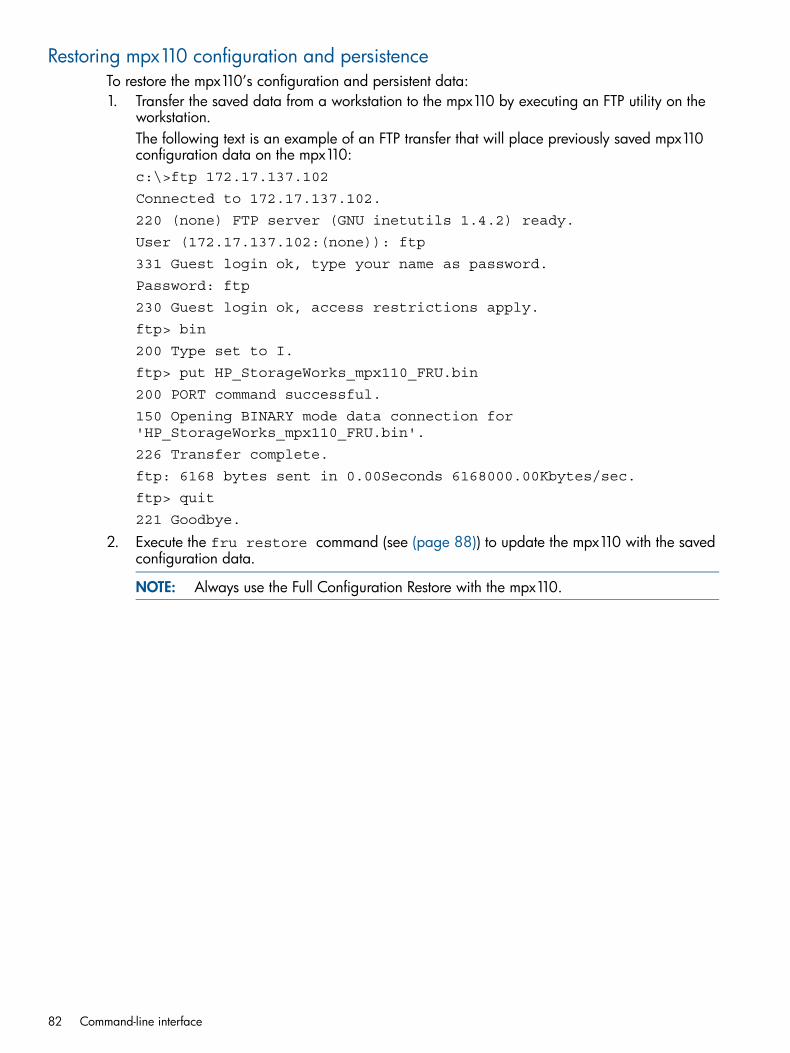
Restoring mpx110 configuration and persistenceTo restore the mpx110’s configuration and persistent data:1. Transfer the saved data from a workstation to the mpx110 by executing an FTP utility on the
workstation.The following text is an example of an FTP transfer that will place previously saved mpx110configuration data on the mpx110:c:\>ftp 172.17.137.102
Connected to 172.17.137.102.
220 (none) FTP server (GNU inetutils 1.4.2) ready.
User (172.17.137.102:(none)): ftp
331 Guest login ok, type your name as password.
Password: ftp
230 Guest login ok, access restrictions apply.
ftp> bin
200 Type set to I.
ftp> put HP_StorageWorks_mpx110_FRU.bin
200 PORT command successful.
150 Opening BINARY mode data connection for'HP_StorageWorks_mpx110_FRU.bin'.
226 Transfer complete.
ftp: 6168 bytes sent in 0.00Seconds 6168000.00Kbytes/sec.
ftp> quit
221 Goodbye.
2. Execute the fru restore command (see (page 88)) to update the mpx110 with the savedconfiguration data.
NOTE: Always use the Full Configuration Restore with the mpx110.
82 Command-line interface
CommandsThe command syntax is as follows:command
keyword
keyword [value]
keyword [value1] [value2]
The command is followed by one or more parameters. Consider the following rules and conventions:• Commands and parameters are not case sensitive.• Required keyword values appear in standard font: [value]. Optional values appear in
italics: [value].• Underlined portions of the keyword in the command format indicate the abbreviated form that
can be used. For example, the Delete keyword can be abbreviated Del.The command-line completion feature makes entering and repeating commands easier.Table 18 (page 83) lists the command-line completion keystrokes.
Table 18 Command-line completion keystrokes
EffectKeystroke
Completes the command-line. Enter at least one character and press the Tab key tocomplete the command-line. If more than one possibility exists, press the Tab key againto display all possibilities.
Tab
Scrolls backward through the list of previously entered commands.Up arrow
Scrolls forward through the list of previously entered commands.Down arrow
Moves cursor to the beginning of the command-line.Ctrl+A
Moves cursor to the end of the command-line.Ctrl+E
The command set performs monitoring and configuration tasks. Commands related to monitoringtasks are available to all account names. Commands related to configuration tasks are availableonly within an Admin session. An account must have Admin authority to enter the admin startcommand, which opens an Admin session. See Admin command (page 84).
Commands 83

Admin commandOpens and closes the Admin session, which provides commands that change mpx110configurations. Only one Admin session can be open on the mpx110 at any time. An inactiveAdmin session times out after 15 minutes.
Admin sessionAuthority
adminSyntax
start or beginOpens the Admin session.
Parameters
end or stopCloses the Admin session. The logout, shutdown, and resetcommands will end an Admin session.
cancel
Terminates an Admin session opened by another user. Use this parameterwith care because it terminates the Admin session without warning theother users and without saving pending changes.
Closing a Telnet window during an Admin session does not release thesession. In this case, you must either wait for the Admin session to timeout, or use the admin cancel command.
Notes
The following example shows how to start and end an Admin session:Examplempx110 #> admin startPassword: ****** mpx110 (admin) #>...mpx110 #> admin endmpx110 #>
84 Command-line interface
Beacon commandEnables or disables flashing the Heartbeat and System Fault LEDs. The Heartbeat and System FaultLEDs are flashed synchronously (they are turned on and off together). No other LEDs are affected.
NoneAuthority
beaconSyntax
on
Turns on the mpx110 beaconParameters
off
Turns off the mpx110 beacon
mpx110 #> beacon onExample
Clear commandAllows you to remove all entries from the mpx110’s log file and/or reset the Fibre Channel andiSCSI statistic counters.
Admin sessionAuthority
clearSyntax
logs
Clears all entries from log fileParameters
stats
Resets statistic counters
The following is an example of the clear command:Examplesmpx110 #>clear logs mpx110 #>clear stats
Date commandDisplays or sets the date and time. To set the date and time, the information string must be providedin this format MMDDhhmmCCYY. The new date and time take effect immediately.
Admin sessionAuthority
date
[MMDDhhmmCCYY]Syntax
[MMDDhhmmCCYY]Specifies the date—This requires an Admin session. If you omit [MMDDhhmmCCYY], thecurrent date appears, which does not require an Admin session.
Parameter
NTP must be disabled to set the time with the date command.NotesSee Set command (page 94) for information about NTP.
The following is an example of the date command:Examplempx110 (admin) #> date 010314282006Tue Jan 3 14:28:00 2006mpx110 (admin) #> dateTue Jan 3 14:28:14 2006
FcipRoute commandThe fciproute command configures a new FCIP route and modifies or deletes an existing FCIProute. Each FCIP route requires a dedicated FC and Gigabit Ethernet (GbE) port. Configuring an
Commands 85
FCIP route and specifying an FC and GE port pair take precedence over any previous configurationfor the port pair (FC/GE).
Admin sessionAuthority
fciprouteSyntax
add
Configures a new FCIP routeParameters
mod
Modifies an existing FCIP routerm
Removes an existing FCIP route
The following is an example of the fciproute add command:Examplesmpx239 (admin) #> fciproute addA list of attributes with formatting and current values will follow. Enter a new value or simply press the ENTER key to accept the current value. If you wish to terminate this process before reaching the end of the list press 'q' or 'Q' and the ENTER key to do so.WARNING: The following command might cause a loss of connections to
both GE ports.
Configuring FCIP Route: 1— — — — — — — — — — — — — — FCIP Interfaces FC & GE (0=Enable, 1=Disable) [Enabled]FC Port (1=FC1, 2=FC2, ...) [FC1]GE Port (1=GE1, 2=GE2, ...) [GE1]IP Address (IPv4 or IPv6; 0=IPv6 Link Local) [0.0.0.0 ] 44.44.1.239Subnet Mask [0.0.0.0 ] 255.255.0.0Gateway IP Address [0.0.0.0 ]Remote IP Address [0.0.0.0 ] 44.44.1.240MTU Size (0=Normal, 1=Jumbo, 2=Other) [Normal]TCP Window Size (0=8KB, 1=16KB, 2=32KB) [32768]Window Scaling (0=Enable, 1=Disable)[Disabled] 0Window Scaling Factor (Min=0, Max=7) [0] 7TCP Port No. (Min=1024, Max=65535) [3225]GE Port Speed (0=Auto, 1=100Mb, 2=1Gb) [Auto]Bandwidth, Mbit/sec (Min=1, Max=1000) [1000] 155VLAN (0=Enable, 1=Disable) [Disabled]FCIP SW Compression (0=Enable, 1=Disable) [Disabled]VLAN (0=Enable, 1=Disable) [Disabled]FCIP SW Compression (0=Enable, 1=Disable) [Disabled]All attribute values for FCIP Route 1 will now be saved.mpx239 (admin) #>
The following is an example of the fciproute modify command:mpx239 (admin) #> fciproute modEnter a new value or simply press the ENTER key to accept thecurrent value.If you wish to terminate this process before reaching the endof the list press 'q' or 'Q' and the ENTER key to do so.WARNING: The following command might cause a loss ofconnections to both GE ports.Route FC Port ID GE Port ID- — — — — — — — — — — — — —1 FC1 GE12 FC2 GE2Please select a FCIP route from the list above ('q' to quit):2Configuring FCIP Route: 2- — — — — — — — — — — — — —
FCIP Interfaces FC & GE (0=Enable, 1=Disable) [Enabled ]IP Address (IPv4 or IPv6; 0=IPv6 Link Local)[2000:33::32:2:239]IPv6 Default Router [::]
86 Command-line interface

Remote IPv6 Address [2000:33::32:2:240]MTU Size (0=Normal, 1=Jumbo, 2=Other) [Normal]TCP Window Size (0=8KB, 1=16KB, 2=32KB) [32768]Window Scaling (0=Enable, 1=Disable) [Enabled]Window Scaling Factor (Min=0, Max=7) [7]TCP Port No. (Min=1024, Max=65535) [3225]GE Port Speed (0=Auto, 1=100Mb, 2=1Gb) [Auto]Bandwidth, Mbit/sec (Min=1, Max=1000) [155]VLAN (0=Enable, 1=Disable) [Disabled]FCIP SW Compression (0=Enable, 1=Disable) [Disabled] 0All attribute values for FCIP Route 2 will now be saved.mpx239 (admin) #>
The following is an example of the fciproute remove command:mpx110 (admin) #> fciproute rmA list of attributes with formatting and current values willfollow. Enter a new value or simply press the ENTER key toaccept the current value. If you wish to terminate thisprocess before reaching the end of the list press 'q' or 'Q'and the ENTER key to do so.WARNING: The following command might cause a loss ofconnections to both GE ports.Route FC Port ID GE Port ID- — — — — — — — — — — — — —1FC2 GE22FC1 GE1Please select an FCIP route from the list above ('q' to quit):1FCIP Route 1 has been removed from the system.
Commands 87
FRU commandSaves and restores the mpx110 configuration.
Admin sessionAuthority
fruSyntax
restore
fru restore requires that the user first ftp the .tar file containing the desiredconfiguration to the mpx110. When this command is issued it prompts the user for the
Parameters
restore level. The user has the option of fully restoring the mpx110’s configuration (allconfiguration parameters and LUN mappings) or restoring only the LUN mappings. Therestored configuration do not take effect until the mpx110 is rebooted.save
fru save creates a .tar file containing the mpx110’s persistent data, configurationand LUN mappings, storing the file in the mpx110's /var/ftp directory. The user mustthen FTP the .bin file from the mpx110.
The following is an example of the fru restore command:Examplesmpx110 (admin) #> fru restoreA list of attributes with formatting and current values willfollow. Enter a new value or simply press the ENTER key toaccept the current value. If you wish to terminate thisprocess before reaching the end of the list press 'q' or 'Q'and the ENTER key to do so.Type of restore (0=full, 1=mappings only) [full] FRU restore completed. Please reboot the system for configuration to take effect.
The following is an example of the fru save command:mpx110 (admin) #> fru saveFRU save completed. Configuration Fileis HP_StorageWorks_mpx110_fru.bin. Please use FTP to extractthe file out from the System.
88 Command-line interface

Help commandDisplays a list of the CLI commands and their syntax.
NoneAuthority
helpSyntax
The following is an example of the help command:Examplempx110 (admin) #> helpadmin [ cancel | start | end ]beacon [ on | off ]date [ <MMDDhhmmCCYY> ]discover [<IP_ADDR> ]clear [ logs | stats ]fciproute [ add | mod | rm ]discoverfru [ restore | save ]historyimage [ cleanup | unpack ]image cleanup
image unpack [ <filename> ]logout passwd ping quit rebootreset factory reset factory save [ capture | logs | traces ]set [ chap | fc | features | iscsi | isns | mgmt | ntp |properties | snmp | system ] set chap set fc [ <PORT_NAME> ]set features set mgmt set ntp set propertiesset snmp [trap_destinations [ <DEST_NUM> ]]set systemshow [ chap | fc | fciproutesfeatures | initiators | iscsiisns | localmaps | logsmemory | mgmt | ntpperf | presented_initiators | presented_targetsproperties | remotemaps | remotepeerssnmp | stats | systemtargets ]
show chapshow fc [ <PORT_NUM> ]show fciproutes [ <LINK_ID> ]show features show initiators [ fc | iscsi ] show logs show memory show mgmt show ntp show perf [ byte | init_rbyte | init_wbyte | tgt_rbyte |tgt_wbyte ] show statsshow system
show properties show snmp show stats show system show targets [ fc | iscsi ]show vlan [ <PORT_NUM> ]shutdown target [ add | rm ]
Commands 89

show chapshow fc [ <PORT_NUM> ]show fciproutes [ <LINK_ID> ]show features show initiators [ fc | iscsi ] show logs show memory show mgmt show ntp show perf [ byte | init_rbyte | init_wbyte | tgt_rbyte |tgt_wbyte ] show statsshow system
show properties show snmp show stats show system show targets [ fc | iscsi ]show vlan [ <PORT_NUM> ]shutdown target [ add | rm ]
History commandDisplays a numbered list of the previously entered commands.
Admin sessionAuthority
historySyntax
Closing a Telnet window during an Admin session does not release the session. In thiscase, you must either wait for the Admin session to time out or use admin cancelcommand.
Notes
The following is an example of the history command:Examplempx110 (admin) #> historympx110 (admin) #> history1: admin start2: help3: historympx110 (admin) #>
90 Command-line interface
Image commandProvides for updating the mpx110’s firmware image and the cleanup (removal) of image files inthe mpx110’s /var/ftp directory.
Admin sessionAuthority
imageSyntax
cleanup
Removes any firmware image file in the mpx110’s /var/ftp directory. These are filestransferred by the user when updating the firmware image.
Parameters
list
Displays a list of the firmware image files in the mpx110’s /var/ftp directory.unpack [<filename>]
Unpacks the firmware image file specified in the <filename> parameter and installsthe firmware image on the mpx110. The mpx110 must be rebooted for the new firmwareimage to be activated. The firmware image file must first have been transferred to thempx110’s /var/ftp directory using FTP.
The following is an example of the image cleanup command:Examplesmpx110 (admin) #> image cleanup
The following is an example of the image list command:mpx110 (admin) #> image listmpx110-2_0_3_2.bin
The following is an example of the image unpack command:mpx110 (admin) #> image unpack mpx110-2_0_3_2.bin Unpack Completed. A reboot is required for the FW to take affect. Do you wish to reboot the System at the current time (y/n): n
Logout commandExits the CLI and returns the operator to the login prompt.
Admin sessionAuthority
logoutSyntax
The following is an example of the logout command:Examplempx110 (admin) #> logout(none) login:
Password commandChanges the guest and administrator passwords.
Admin session required only to set the commandAuthority
passwordSyntax
The following is an example of the password command:Examplempx110 (admin)#> passwdPress 'q' and the ENTER key to abort this command.Select password to change (0=guest, 1=admin): 1account OLD password : ******account NEW password (6-128 chars) : ******please confirm account NEW password : ******Password has been changed.
Commands 91
Ping commandVerifies the connectivity of each Ethernet port: management, GE1 (iSCSI 1), and GE2 (iSCSI 2).
Admin sessionAuthority
pingSyntax
mpx239 (admin) #> pingA list of attributes with formatting and current values
Example
will follow.Enter a new value or simply press the ENTER key toaccept the current value. If you wish to terminate thisprocess before reaching the end of the list press 'q' or'Q' and the ENTER key to do so.IP Address (IPv4 or IPv6) [0.0.0.0] 44.44.1.240Iteration Count (0=Continuously) [0 ] 10Outbound Port (0=Mgmt, 1=GE1, 2=GE2, ...) [Mgmt ] 1Size Of Packet (Min=1, Max=62256 Bytes) [56 ] 62256Pinging 44.44.1.240 with 62256 bytes of data:
Reply from 44.44.1.240: bytes=62264 time=109.0ms Reply from 44.44.1.240: bytes=62264 time=108.5ms Reply from 44.44.1.240: bytes=62264 time=108.5ms Reply from 44.44.1.240: bytes=62264 time=108.5ms Reply from 44.44.1.240: bytes=62264 time=108.5ms Reply from 44.44.1.240: bytes=62264 time=108.6ms Reply from 44.44.1.240: bytes=62264 time=108.5ms Reply from 44.44.1.240: bytes=62264 time=108.4ms Reply from 44.44.1.240: bytes=62264 time=108.5ms
Ping Statistics for 44.44.1.240:Packets: Sent = 10, Received = 9, Lost = 1Minimum = 108.4ms, Maximum = 109.0ms, Average = 108.5ms
mpx239 (admin) #>
Quit commandExits the CLI and returns the operator to the login prompt.
Admin sessionAuthority
quitSyntax
The following is an example of the quit command:Examplempx110 (admin) #> quit (none) login:
Reboot commandRestarts the mpx110 firmware.
Admin sessionAuthority
rebootSyntax
The following is an example of the reboot command:Examplempx110 (admin) #> reboot Are you sure you want to reboot the System (y/n): y System will now be rebooted...
92 Command-line interface

Reset factory commandRestores the mpx110 factory default values. All LUN mappings are deleted, as are all persistentdata regarding targets, LUNS, and initiators. The factory default IP addresses are restored.
Admin sessionAuthority
resetSyntax
factory
Restores mpx110 to factory default configuration.Parameter
The following is an example of the reset factory command:Examplempx110 (admin) #> reset factoryAre you sure you want to restore to factory defaultsettings (y/n): y Please reboot the System for thesettings to take affect.
Commands 93
Save commandSaves logs and traces.
Admin sessionAuthority
saveSyntax
capture
Creates a debug file that captures all debug dump data. After the command completes,you must FTP the debug capture file from the mpx110.
Parameters
logs
Creates a .tar file containing the mpx110’s log data, storing the file in the mpx110's/var/ftp directory. The operator must then FTP the logs .tar file from the mpx110.traces
Creates a .tar file containing the mpx110’s dump data storing the .tar file in thempx110’s /var/ftp directory. The operator must then FTP the trace's .tar file fromthe mpx110. If the mpx110 does not have any dump data, the operator will be notifiedwhen executing this command. An event log entry is generated whenever a data dumpis generated.
The following is an example of the save capture command:Examplesmpx110 (admin) #> save capture Debug capture completed. Package is System_Capture.tar.gz Please use FTP to extract the file out fromthe System.
The following is an example of the save logs command:mpx110 (admin) #> save logs Save Event Logs completed. Package is System_Evl.tar.gzPlease use FTP to extract the file out from the System.
The following is an example of the save traces command:mpx110 (admin) #> save tracesSave ASIC Traces completed. Packageis System_Asic_Trace.tar.gz. Please use FTP to extract the fileout from the System.mpx110 (admin) #> save tracesNo ASIC tracefiles exist to save. Command aborted.
Set commandConfigures general parameters, as well as parameters for the FC, iSCSI, and management ports.
Admin sessionAuthority
setSyntax
chap
Sets CHAP secretsParameters
mgmt
Sets management port parametersntp
Sets NTP parametersproperties
Sets CLI propertiessnmp
Sets SNMP parameterssystem
Sets system parameters
The following is an example of the set command:Examplempx110 #>set mgmt
94 Command-line interface

Set FC commandConfigures an FC port.
Admin sessionAuthority
set fc [port_num]Syntax
port_num
Sets the number of the FC port to be configuredParameter
The following is an example of the set fc command:Examplempx239 (admin) #> set fc 1A list of attributes with formatting and current values will follow. Enter a new value or simply press the ENTER key
to accept the current value.If you wish to terminate this process before reaching the end of the list press 'q' or 'Q' and the ENTER key to do so.WARNING:The following command might cause a loss of connections to both ports.Configuring FC Port: 1-------------------------Port Status (0=Enable, 1=Disable) [Enabled]Link Rate (0=Auto, 1=1Gb, 2=2Gb) [Auto]Frame Size (0=512B, 1=1024B, 2=2048B) [2048]Execution Throttle (Min=16, Max=256) [64]
All attribute values for Port 1 that have been changed will nowbe saved.
mpx239 (admin) #>
Commands 95

Set MGMT commandConfigures the mpx110 management port (10/100).
Admin sessionAuthority
set mgmtSyntax
The following is an example of the set mgmt command:Examplempx239 (admin) #> set mgmtA list of attributes with formatting and current valueswill follow. Enter a new value or simply press theENTER key to accept the current value. If you wish to terminate this process before reachingthe end of the list press 'q' or 'Q' and the ENTER keyto do so. WARNING: The following command might cause a loss of connectionsto the MGMT port. IPv4 Interface (0=Enable, 1=Disable) [Enabled] IPv4 Mode (0=Static, 1=DHCP, 2=Bootp, 3=Rarp) [Static] IPv4 Address [10.6.7.239] IPv4 Subnet Mask [255.255.248.0] IPv4 Gateway [10.6.4.200] IPv6 Interface (0=Enable, 1=Disable) [Disabled] 0 IPv6 Mode (0=Manual, 1=AutoConfigure) [Manual] IPv6 Address 1 [:: ] 2000:10::32:239:1 IPv6 Address 2 [:: ] IPv6 Default Router [:: ] All attribute values that have been changed will now besaved.mpx239 (admin) #>98 Command-
All attribute values that have been changed will now be saved.
mpx239 (admin) #>
96 Command-line interface
Set NTP commandConfigures NTP parameters.
Admin sessionAuthority
set ntpSyntax
The following is an example of the set ntp command:Examplempx110 (admin) #> set ntp NTP (0=Enable, 1=Disable) [Enabled ] TimeZone Offset from GMT (Min=-12hrs,Max=12hrs) [-8 ] IP Address [0] [0.0.0.0 ] 207.126.97.57IP Address [1] [0.0.0.0 ]IP Address [2] [0.0.0.0 ]All attribute values that have been changed will now besaved.
Set Properties commandConfigures CLI properties.
Admin sessionAuthority
set propertiesSyntax
The following is an example of the set properties command:mpx110 (admin) #> set propertiesA list of attributes with formatting and current values will
Examples
follow. Enter a new value or simply press the ENTER key toaccept the current value. If you wish to terminate thisprocess before reaching the end of the list press 'q' or 'Q'and the ENTER key to do so.CLI Inactivity Timer (0=Disable 1=15min, 2=60min) [Disabled]CLI Prompt (Max=32 Characters) [mpx110 ] RTR1All attribute values that have been changed will now be saved.
Commands 97
Set SNMP commandConfigures general SNMP properties. It also provides for configuration of up to eight trapdestinations.
Admin sessionAuthority
set snmpSyntax
trap_destinations
Sets the number of the trap destinations to be configured for SNMPParameter
The following is an example of the set snmp command:mpx110 (admin) #> set snmp A list of attributes with formatting and current values will
Examples
follow. Enter a new value or simply press the ENTER key toaccept the current value. If you wish to terminate thisprocess before reaching the end of the list press 'q' or 'Q'and the ENTER key to do so.Configuring SNMP: ----------------- Read Community [ ] Public Trap Community [ ] Private System Location [ ] System Contact [ ] Authentication Traps (0=Enable, 1=Disable) [Disabled] All attribute values that have been changed will now be saved
The following is an example of configuring an SNMP trap destination:mpx239 (admin) #> set snmp trap_destinationsA list of attributes with formatting and current values willfollow. Enter a new value or simply press the ENTER key toaccept the current value. If you wish to terminate thisprocess before reaching the end of the list press 'q' or 'Q'and the ENTER key to do so.Configuring SNMP Trap Destination 1 : ------------------------------------- Destination enabled (0=Enable, 1=Disable) [Disabled] 0 IP Address (IPv4 or IPv6)[0.0.0.0] 10.6.6.28 Destination Port [0] Trap Version [0] Configuring SNMP Trap Destination 2 :—------------------------------------- Destination enabled (0=Enable, 1=Disable) [Disabled ] Configuring SNMP Trap Destination 3 : ------------------------------------- Destination enabled (0=Enable, 1=Disable) [Disabled ] Configuring SNMP Trap Destination 4 : ------------------------------------- Destination enabled (0=Enable, 1=Disable) [Disabled ] Configuring SNMP Trap Destination 5 : ------------------------------------- Destination enabled (0=Enable, 1=Disable) [Disabled ] Configuring SNMP Trap Destination 6 : ------------------------------------- Destination enabled (0=Enable, 1=Disable) [Disabled ] Configuring SNMP Trap Destination 7 : ------------------------------------- Destination enabled (0=Enable, 1=Disable) [Disabled ] Configuring SNMP Trap Destination 8 : ------------------------------------- Destination enabled (0=Enable, 1=Disable) [Disabled ] All attribute values that have been changed will now be saved mpx239 (admin) #>
Set System commandConfigures general mpx110 parameters.
Admin sessionAuthority
set systemSyntax
port_num
Sets the number of the iSCSI port to be configured for iSNSParameter
The following is an example of the set system command:Example
98 Command-line interface

mpx110 (admin) #> set system A list of attributes with formatting and current values will follow. Enter a new value or simply press the ENTER key to accept the current value. If you wish to terminate this process before reaching the end of the list press 'q' or 'Q' and the ENTER key to do so. System Symbolic Name (Max = 64 characters) [ ] testing
Mode (0=Normal, 1=Transparent, 2=Encap_FC) [0 ] System Log Level (Min = 0, Max = 3) [0 ] All attribute values that have been changed will now be saved.
Commands 99
Show commandDisplays operational information.
NoneAuthority
show [keyword]Syntax
fciproutes [link_id]ParametersShows FCIP routes in effect and their configuration parameterslogs
Shows contents of the mpx110 logs.memory
Shows memory managed by the mpx110; includes total and availablemgmt
Shows the mpx110 management port configurationntp
Shows the NTP configurationperf [ byte | init_rbyte | init_wbyte | tgt_rbyte | tgt_wbyte]
Shows performance data.properties
Shows the mpx110 CLI propertiessnmp
Shows the mpx110 SNMP properties and trap configurationsstats
Shows the mpx110 statistics, both FC and iSCSIsystem
Shows product information, including serial number, software version, hardware version,configuration, and temperature
The following is an example of the show command:Examplempx110 #> show mpx110 QRouter Information -------------------- Product Name QRouter Symbolic Name Rack3 QRouter Mode iSCSI Server Connectivity Mode Serial Number 0539A01070 HW Version 2 SW Version 1.0.5.0 No. of FC Ports 2 No. of iSCSI Ports 2 Log Level 0 Log Length (KB) 32768 Temperature (C) 32
100 Command-line interface

Show FcipRoutes commandShows FCIP route configuration parameters.
NoneAuthority
show fciproutesSyntax
[link_id]
Sets the number of the FCIP route to be displayed (1 or 2)Parameter
The following is an example of the show fciproutes command:Examplempx239 (admin) #> show fciproutes FCIP Route Information ------------------------ FCIP Route 1 FCIP Interfaces Status Enabled FCIP Link Status Up FC Port FC1 GE Port GE1 GE Link Status Up Local IP Address 44.44.1.239 Remote IP Address 44.44.1.240 Subnet Mask 255.255.0.0 Gateway IP Address 0.0.0.0 MTU Size Normal TCP Window Size 32768 Window Scaling Enabled Window Scaling Factor 7 TCP Port No 3225 Current GE Port Speed 1Gb/FDX Programmed GE Port Speed Auto Bandwidth, Mbit/sec 155 VLAN Disabled FCIP SW Compression Disabled FCIP Route 2 FCIP Interfaces Status Enabled FCIP Link Status Up FC Port FC2 GE Port GE2 GE Link Status Up IPv6 Address 1 2000:33::32:2:239 IPv6 Link Local fe80::2c0:ddff:fe0d:b27b IPv6 Remote Address 2000:33::32:2:240 MTU Size Normal TCP Window Size 32768 Window Scaling Enabled Window Scaling Factor 7 TCP Port No 3225 Current GE Port Speed 1Gb/FDX Programmed GE Port Speed Auto Bandwidth, Mbit/sec 155 VLAN Disabled FCIP SW Compression Disabled mpx239 (admin) #>
Commands 101
Show Logs commandShows the mpx110 event log.
NoneAuthority
show logsSyntax
The following is an example of the show logs command:Examplempx110 #> show logs 01/01/1970 00:00:13 System 3 Thursday 01 January 12:13 AM 01/01/1970 00:00:21 QL4022 3 #0: QLIsrDecodeMailbox: Link up 01/01/1970 00:00:13 System 3 Thursday 01 January 12:13 AM 01/01/1970 00:00:22 QL4022 3 #0: QLIsrDecodeMailbox: Link up
Show Memory commandShows the mpx110 memory usage. The FCIP memory usage is zero (0) if there are no FCIP routesconfigured.
NoneAuthority
show memorySyntax
The following is an example of the show memory command:Examplesmpx110 #> show memory Memory Units Free/Total-------------- ---------- Physical 15MB/505MB Buffer Pool 11520/12544 Process Blocks 8192/8192 Request Blocks 8192/8192 Event Blocks 1024/1024 Control Blocks 256/256 FCIP Buffer Pool 0/0 FCIP Request Blocks 16384/16384
The following is an example of the show memory command with one FCIP routeconfigured:mpx110 #> show memory Memory Units Free/Total -------------—---------- Physical 28MB/251MB Buffer Pool 2176/4224 Process Blocks 4096/4096 Request Blocks 4096/4096 Event Blocks 512/512 Control Blocks 128/128 FCIP Buffer Pool 13320/16384 FCIP Request Blocks 15368/16384
102 Command-line interface
Show MGMT commandShows the management port (10/100) configuration.
NoneAuthority
show mgmtSyntax
The following is an example of the show mgmt command:Examplempx239 (admin) #> show mgmt Management Port Information ----------------------------- IPv4 Interface Enabled IPv4 Mode Static IPv4 IP Address 10.6.7.239 IPv4 Subnet Mask 255.255.248.0 IPv4 Gateway 10.6.4.200 IPv6 Interface Enabled IPv6 Mode Manual IPv6 Address 1 2000:10::32:239:1 IPv6 Address 2 :: IPv6 Link Local fe80::2c0:ddff:fe0d:b279IPv6 Default Router :: Link Status Up MAC Address 00-c0-dd-0d-b2-79
Show NTP commandShows the NTP configuration.
NoneAuthority
show ntpSyntax
The following is an example of the show ntp command:Examplempx110 #> show ntp NTP Information ----------------- Mode Disabled Status Offline TimeZone Offset (Hours) 0
Commands 103
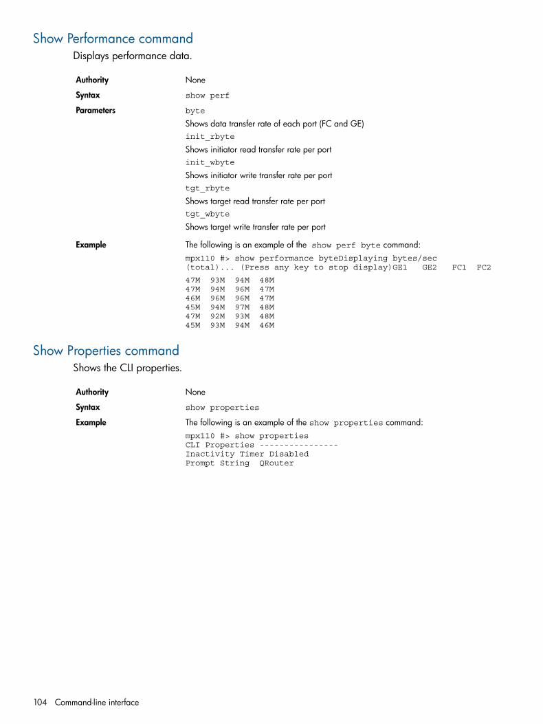
Show Performance commandDisplays performance data.
NoneAuthority
show perfSyntax
byte
Shows data transfer rate of each port (FC and GE)Parameters
init_rbyte
Shows initiator read transfer rate per portinit_wbyte
Shows initiator write transfer rate per porttgt_rbyte
Shows target read transfer rate per porttgt_wbyte
Shows target write transfer rate per port
The following is an example of the show perf byte command:Examplempx110 #> show performance byteDisplaying bytes/sec (total)... (Press any key to stop display)GE1 GE2 FC1 FC2
47M 93M 94M 48M 47M 94M 96M 47M 46M 96M 96M 47M 45M 94M 97M 48M 47M 92M 93M 48M 45M 93M 94M 46M
Show Properties commandShows the CLI properties.
NoneAuthority
show propertiesSyntax
The following is an example of the show properties command:Examplempx110 #> show properties CLI Properties ---------------- Inactivity Timer Disabled Prompt String QRouter
104 Command-line interface

Show SNMP commandDisplays the mpx110’s SNMP properties and any traps that have been configured.
NoneAuthority
show snmpSyntax
The following is an example of the show snmp command:ExampleQRouter #> show snmp SNMP configuration ------------------------------Read Community Public Trap Community Private System Location System Contact Authentication traps System OID 1.3.6.1.4.1.3873.1.4 System Description HP mpx110Trap Destination 1 IP Address 10.0.0.5 Trap Port 1024 Trap Version 2
Commands 105

Show Stats commandDisplays mpx110 statistics for FC and iSCSI.
NoneAuthority
show statsSyntax
The following is an example of the show stats command:Examplempx110 #> show stats FC Port Statistics -------------------- FC Port Interrupt Count Target Command Count Initiator Command Count FC PortInterrupt CountTarget Command Count Initiator Command CountiSCSI Port Statistics
----------------------- iSCSI Port Interrupt Count Target Command Count Initiator Command Count MAC Xmit Frames MAC Xmit Byte CountMAC Xmit Multicast Frames MAC Xmit Broadcast Frames MAC Xmit Pause Frames MAC Xmit Control Frames MAC Xmit Deferrals
MAC Xmit Late CollisionsMAC Xmit Aborted MAC Xmit Single Collisions MAC Xmit Multiple Collisions MAC Xmit CollisionsMAC Xmit Dropped Frames MAC Xmit Jumbo Frames MAC Rcvd Frames MAC Rcvd Byte Count MAC Rcvd Unknown Control Frames MAC Rcvd Pause Frames MAC Rcvd Control Frames MAC Rcvd Dribbles
MAC Rcvd Frame Length Errors MAC Rcvd Jabbers MAC Rcvd Carrier Sense Errors MAC Rcvd Dropped Frames MAC Rcvd CRC Errors MAC Rcvd Encoding Errors MAC Rcvd Length Errors Large MAC Rcvd Small Errors Small MAC Rcvd Multicast Frames MAC Rcvd Broadcast Frames
FC PortFC PortInterrupt CountTarget Command CountInitiator Command Count iSCSI Port 2 Interrupt CountTarget Command Count Initiator Command Count
106 Command-line interface

MAC Xmit Frames MAC Xmit Byte Count
MAC Xmit Multicast FramesMAC Xmit Broadcast Frames MAC Xmit Pause Frames MAC Xmit Control Frames MAC Xmit Deferrals MAC Xmit Late Collisions MAC Xmit Aborted MAC Xmit Single Collisions MAC Xmit Multiple Collisions MAC Xmit Collisions
MAC Xmit Dropped Frames MAC Xmit Jumbo Frames MAC Rcvd Frames MAC Rcvd Byte Count MAC Rcvd Unknown Control FramesMAC Rcvd Pause FramesMAC Rcvd Control Frames MAC Rcvd Dribbles MAC Rcvd Frame Length Errors MAC Rcvd Jabbers
MAC Rcvd Carrier Sense Errors MAC Rcvd Dropped Frames MAC Rcvd CRC Errors MAC Rcvd Encoding Errors MAC Rcvd Length Errors Large MAC Rcvd Small Errors Small MAC Rcvd Multicast Frames MAC Rcvd Broadcast Frames
iSCSI Shared Statistics----------------------- PDUs XmitedData Bytes XmitedPDUs RcvdData Bytes RcvdI/O CompletedUnexpected I/O RcvdiSCSI Format ErrorsHeader Digest ErrorsData Digest ErrorsSequence Errors
PDU Xmit CountPDU Xmit CountPDU Xmit CountIP Xmit PacketsIP Xmit Byte CountIP Xmit FragmentsIP Rcvd PacketsIP Rcvd Byte CountIP Rcvd FragmentsIP Datagram Reassembly Count
IP Error PacketsIP Fragment Rcvd OverlapIP Fragment Rcvd Out of OrderIP Datagram Reassembly Timeouts TCP Xmit Segment Count TCP Xmit Byte CountTCP Rcvd Segment CountTCP Rcvd Byte CountTCP Persist Timer Expirations
Commands 107

TCP Rxmit Timer ExpiredTCP Rcvd Duplicate Acks
TCP Rcvd Pure AcksTCP Xmit Delayed AcksTCP Rcvd Pure AcksTCP Rcvd Segment ErrorsTCP Rcvd Segment Out of OrderTCP Rcvd Window ProbesTCP Rcvd Window UpdatesTCP ECC Error Corrections
108 Command-line interface
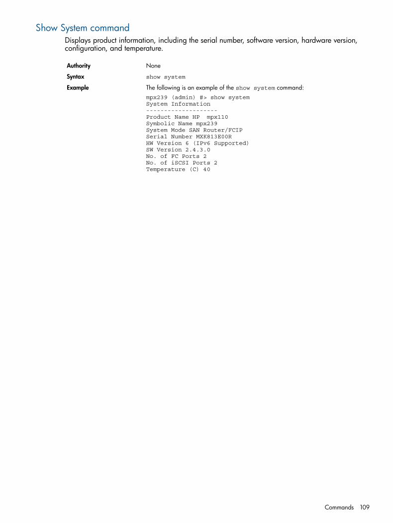
Show System commandDisplays product information, including the serial number, software version, hardware version,configuration, and temperature.
NoneAuthority
show systemSyntax
The following is an example of the show system command:Examplempx239 (admin) #> show system System Information -------------------- Product Name HP mpx110 Symbolic Name mpx239 System Mode SAN Router/FCIP Serial Number MXK813E00R HW Version 6 (IPv6 Supported) SW Version 2.4.3.0 No. of FC Ports 2 No. of iSCSI Ports 2 Temperature (C) 40
Commands 109
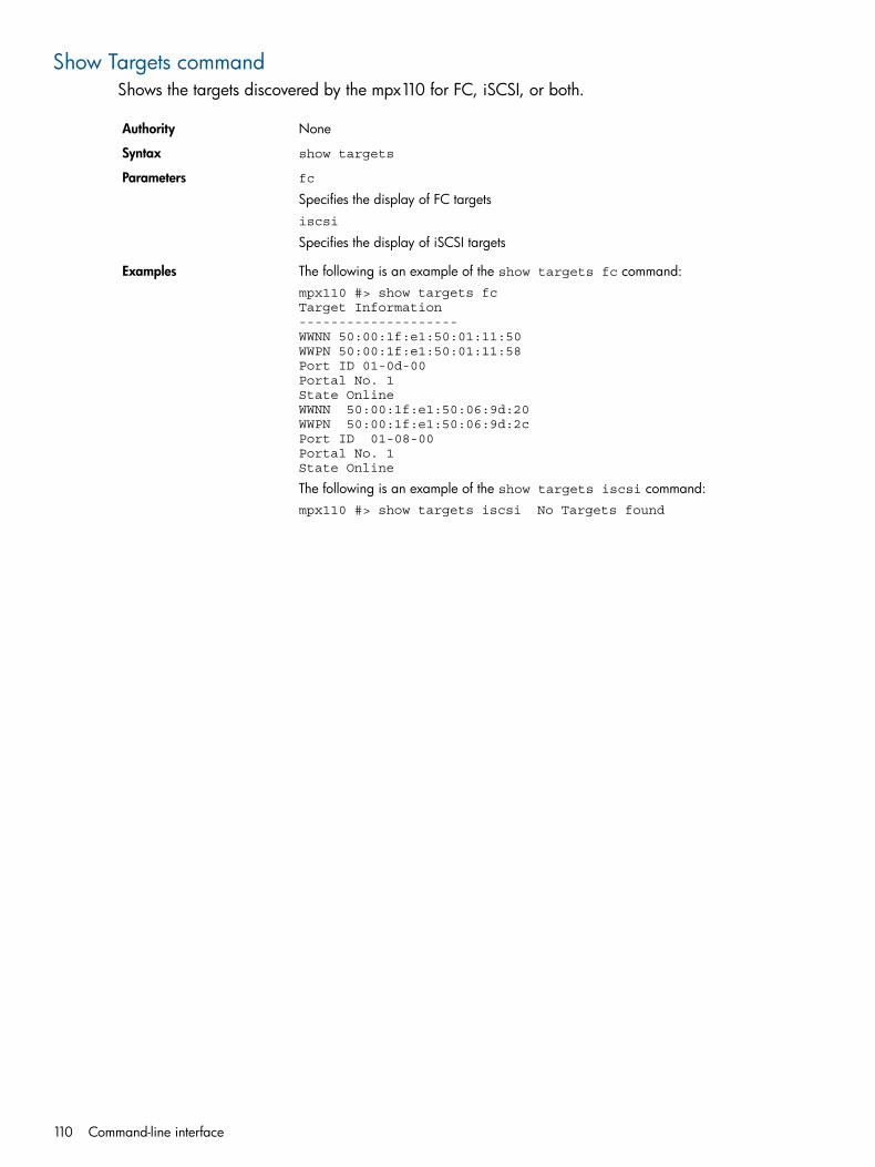
Show Targets commandShows the targets discovered by the mpx110 for FC, iSCSI, or both.
NoneAuthority
show targetsSyntax
fc
Specifies the display of FC targetsParameters
iscsi
Specifies the display of iSCSI targets
The following is an example of the show targets fc command:Examplesmpx110 #> show targets fc Target Information -------------------- WWNN 50:00:1f:e1:50:01:11:50 WWPN 50:00:1f:e1:50:01:11:58 Port ID 01-0d-00 Portal No. 1 State Online WWNN 50:00:1f:e1:50:06:9d:20 WWPN 50:00:1f:e1:50:06:9d:2c Port ID 01-08-00 Portal No. 1 State Online
The following is an example of the show targets iscsi command:mpx110 #> show targets iscsi No Targets found
110 Command-line interface
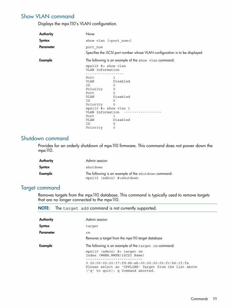
Show VLAN commandDisplays the mpx110’s VLAN configuration.
NoneAuthority
show vlan [<port_num>]Syntax
port_num
Specifies the iSCSI port number whose VLAN configuration is to be displayedParameter
The following is an example of the show vlan command:Examplempx110 #> show vlan VLAN Information ------------------ Port 1 VLAN Disabled ID 0 Priority 0 Port 2 VLAN Disabled ID 0 Priority 0 mpx110 #> show vlan 1 VLAN Information ------------------ Port 1 VLAN Disabled ID 0 Priority 0
Shutdown commandProvides for an orderly shutdown of mpx110 firmware. This command does not power down thempx110.
Admin sessionAuthority
shutdownSyntax
The following is an example of the shutdown command:Examplempx110 (admin) #>shutdown
Target commandRemoves targets from the mpx110 database. This command is typically used to remove targetsthat are no longer connected to the mpx110.
NOTE: The target add command is not currently supported.
Admin sessionAuthority
targetSyntax
rmParameterRemoves a target from the mpx110 target database
The following is an example of the target rm command:Examplempx110 (admin) #> target rm Index (WWNN,WWPN/iSCSI Name) --------------------------- 0 20:00:00:20:37:fd:8b:ab:00:00:00:00:fc:b6:1f:fa Please select an 'OFFLINE' Target from the list above ('q' to quit): q Command aborted.
Commands 111

Traceroute commandTracks the route that packets take across an IP network on their way to an IP host.
Admin sessionAuthority
tracerouteSyntax
The following is an example of the traceroute command:mpx239 (admin) #> tracerouteA list of attributes with formatting and current values will follow. Enter a new value or simply press the ENTER keyto accept the current value. To
Example
terminate this process before reaching the end of the list, press q or Qand the ENTERkey.IP Address (IPv4 or IPv6) [0.0.0.0] 44.44.1.240 Outbound Port (0=Mgmt, 1=GE1, 2=GE2, ...) [Mgmt ] 1 Tracing route to 44.44.1.240 over a maximum of 30 hops: 1 44.44.1.240 201.4ms 100.2ms 100.2ms Traceroute completed in 1 hops.
112 Command-line interface

B Log dataThe mpx110 maintains a message log that can be displayed and retrieved by the operator, eitherthrough the CLI or the mpx110 Manager GUI. The message log is persistent in that it is maintainedacross mpx110 power cycles and reboots. The three log categories are described in this appendix.
Informational log messagesThe following sections describe the informational log messages by reporting module.
Application modulesTable 19 (page 113) lists informational log messages provided by application modules.
Table 19 Application modules—Informational log messages
DescriptionNo.Log messageID
Router is booting up6System (router) Booting up53254
Decompression failed and willbe temporarily disabled
109QLBA_ProcessTpb: De-compression failed. Disablingcompression temporarily
53357
User removed a target (iSR6140or iSR6142) or a targetpresentation (iSR6142)
110QLBA_RemoveTargetNodeObject : TargetNode %s53358
FC logout occurred, origin xx (1= HBA, 2 = target, 3 = initiator)VPxx, ID (loop ID) x
1026QLFC_Login: Origin 0x%x, VP Index 0x%x, Id 0x%x54274
FC login occurred with port IDxx.xx.xx
1027QLFC_Login: Port ID %.2x%.2x%.2x54275
FC login occurred with WWNNxx.xx.xx.xx.xx.xx.xx.xx
1028QLFC_Login: Node Name%.2x%.2x%.2x%.2x%.2x%.2x%.2x%.2x
54276
FC login occurred with WWPNxx.xx.xx.xx.xx.xx.xx.xx
1029QLFC_Login: Port Name%.2x%.2x%.2x%.2x%.2x%.2x%.2x%.2x
54277
FC logout occurred, origin xx (1= HBA, 2 = target, 3 = initiator)VP xx, ID (loop ID) x
1058QLFC_Logout: Origin 0x%x, VP Index 0x%x, Id 0x%x54306
FC logout occurred with port IDxx.xx.xx
1059QLFC_Logout: Port ID %.2x%.2x%.2x54307
FC logout occurred withWWNNxx.xx.xx.xx.xx.xx.xx.xx
1060QLFC_Logout: Node Name%.2x%.2x%.2x%.2x%.2x%.2QLFC_Logout: PortNamex%.2x%.2x
54308
FC logout occurred withWWPNxx.xx.xx.xx.xx.xx.xx.xx
1061QLFC_Logout: Port Name%.2x%.2x%.2x%.2x%.2x%.2x%.2x%.2x
54309
FC login event notification, VPxx
1111QLFC_HandleTeb: FC Login. VP 0x%x54359
Maximum number of supporthosts dd has been reached
1120QLFC_CreateVirtualInitiatorObject: Maximum host (%d)limit reached.
54368
An iSCSI initiator logged out ofa router presented target.
1331QLIS_CloseSession: Initiator logged out54579
An iSCSI initiator logged into arouter presented target.
1435QLIS_OpenConnectionNotification: Target connectionopened (Port %d, DDB %d)
54683
Event notification: iSCSI openconnection request
1690QLIS_HandleTeb: UTM_EC_OPEN_CONNECTION54938
Informational log messages 113

Table 19 Application modules—Informational log messages (continued)
DescriptionNo.Log messageID
Event notification: iSCSI closeconnection request orconnection closed.
1691QLIS_HandleTeb: UTM_EC_CLOSE_CONNECTION orUTM_EC_CONNECTION_CLOSED
54939
Event notification: iSCSIconnection opened
1692QLIS_HandleTeb: UTM_EC_CONNECTION_OPENED54940
Event notification: connectionopened with iSNS server
1693QLIS_HandleTeb:iSNS Server Open Connection succeeded54941
Event notification: iSNS SCNreceived
1695QLIS_HandleTeb: UTM_EC_ISNS_SCN54943
Event notification: iSNS clientdiscovered.
1697QLIS_HandleTeb: UTM_EC_ISNS_CLIENT_DISCOVERED54945
iSCSI close connection requestreceived
1699QLIS_HandleTeb: UTM_EC_CLOSE_CONNECTION54947
iSCSI connection closed1700QLIS_HandleTeb: UTM_EC_CONNECTION_CLOSED54948
Remote system connectionestablished using DDB d:d
1715QLIS_SetDdbEntryContinue:[%d:%d] Remote systemconnection established
54963
Router iSCSI port xx, operatingas an ISCSI initiator, opened aconnection with an iSCSI target.
1716QLIS_ConnectionOpenedNotification: Initiator connectionopened (Port %d, DDB %d)
54964
Re-enabling compression1738QLIS_HandleSessionTimer: Re-enabling compression54986
TRB freed, State xx, AbortReason d, Flags xx
2051QLSC_CollectBUVUIO: Freeing dead TRB: State 0x%02X,AbortReason %d, Flags 0x%02X
55299
iSCSI driverTable 20 (page 114) lists log messages common to both iSCSI ports, 1 (GE1) and 2 (GE2). Logmessages beginning with #0 apply to iSCSI port 1 (GE1), and log messages beginning with #1apply to iSCSI port 2 (GE2).
Table 20 SCSI driver—Informational log messages
DescriptionNo.Log messageID
iSCSI port enabled, port up331 Restart iSCSIprocessor (RISC)
327#%d: QLPortUp: Set link configuration 0x%x86343
Restart iSCSI processor(RISC)
331#%d: QLDisable: Restart RISC86347
EEPROM updated, restartiSCSI processor (RISC)
333#%d: QLEnable: Restart RISC to update EEPROM86349
iSCSI port disabled, portdown
336#%d: QLPortDown: Set link configuration 0x%x86352
Link up reported by iSCSIprocessor for GE1 or GE 2
858#%d: QLIsrDecodeMailbox: Link up86874
Not used. To be used on6200 in outbound offloadcode.
1289#%d: ql4xxx_offload_init: Outbound offload initializationcompleted
87305
iSCSI port link-up at100Mb full-duplex
1330#%d: QLGetFwStateCallback: link 100Mb FDX87346
114 Log data
Table 20 SCSI driver—Informational log messages (continued)
DescriptionNo.Log messageID
iSCSI port link-up at100Mb half-duplex
1331#%d: QLGetFwStateCallback: link 100Mb HDX87347
iSCSI port link-up at1000Mb full-duplex
1332#%d: QLGetFwStateCallback: link 1000Mb FDX87348
iSCSI port link-up at1000Mb half-duplex
1333#%d: QLGetFwStateCallback: link 1000Mb HDX87349
iSCSI port link speed couldnot be determined. Link
1334#%d: QLGetFwStateCallback: Invalid link speed 0x%x87350
speed may be incorrectlyprogrammed
Informational log messages 115

Fibre Channel driverTable 21 (page 116) lists informational log messages common to both FC ports, 1 (FC1) and 2(FC2). Log messages beginning with #0 apply to Fibre Channel port 1 (FC1), and log messagesbeginning with #1 apply to Fibre Channel port 2 (FC2).
Table 21 FC driver—Informational log messages
DescriptionNo.Log messageID
Request to reset the FCprocessor (adapter) receivedfrom IOCTL interface.
98#%d: QLIoctlDisable: Reset adapter118882
LIP occurred. The LIP type isreported, as is the contents of
304#%d: QLIsrEventHandler: LIP occurred (%x): mailbox1 =%x
119088
the FC processor’s mailbox 1register.
Fibre Channel LIP resetoccurred. The LIP reset type is
305#%d: QLIsrEventHandler: LIP reset occurred (%x): mailbox1= %x
119089
reported, as is the contents ofthe FC processor’s mailbox 1register.
Fibre Channel link up occurred.Event status is reported, as is
306#%d: QLIsrEventHandler: Link up (%x) mailbox1 = %x119090
the contents of the FCprocessor’s mailbox 1 register.
Fibre Channel link up occurred.Event status is reported, as is
308#%d: QLIsrEventHandler: Link mode up (%x):RunTimeMode=%x
119092
the RunTimeMode (0 = loop, 1= point-to-point).
An RSCN was received. Eventstatus is reported, as is theRSCN information.
309#%d: QLIsrEventHandler: RSCN update (%x) rscnInfo: %x119093
Fibre Channel port update.Event status is reported, as is
313#%d: QLIsrEventHandler: Port update (%x) mb1-3 %x %x%x
119097
the contents of the FCprocessor’s mailbox 1, 2, and3 registers.
FCIP-Fibre Channel link upoccurred. Event status is
768#%d: QLFcipIsrEventHandler: Link up (%x) mailbox1 = %x119552
reported, as is the contents ofthe FC processor’s mailbox 1register.
FCIP-Fibre Channel link downoccurred.
769#%d: QLFcipIsrEventHandler: Link down (%x)119553
FCIP-Fibre Channel link upoccurred. Event status is
770#%d: QLFcipIsrEventHandler: Link mode up (%x)119554
reported, as is theRunTimeMode (0 = loop, 1 =point-to-point).
116 Log data
User modulesTable 22 (page 117) lists log messages provided by user modules.
Table 22 User modules—Log messages
DescriptionNo.Log messageID
Router firmware upgradeperformed, new version number isd.d.d.d.
290FW Upgrade performed: new version is:%d.%d.%d.%d
151842
User performed a router reboot orshutdown.
291REBOOT/SHUTDOWN Command from user.Code=%d
151843
FC port configuration has beenmodified.
337#%d: qapisetfcinterfaceparams_1_svc: FC portconfiguration changed
151889
iSCSI port configuration has beenmodified.
338#%d: qapisetiscsiinterfaceparams_1_svc: iSCSI portconfiguration changed
151890
iSNS configuration has beenmodified.
339#%d: qapisetisns_1_svc:iSNS configurationchanged
151891
NTP configuration has beenmodified.
340qapisetntpparams_1_svc: NTP configurationchanged
151892
VLAN configuration has beenmodified.
341#%d: qapisetvlanparams_1_svc: VLANconfiguration changed
151893
User presented a LUN to an initiator342qapisetlunmask_1_svc: Lunmask added for LUN %d151894
User unpresented a LUN to aninitiator
343qapisetlunmask_1_svc: Lunmask removed for LUN%d
151895
Management Ethernet portconfiguration has been modified.
344qapisetmgmintfcparams_1_svc:Management portconfiguration changed
151896
Router configuration has beenmodified.
345qapisetbridgebasicinfo_1_svc:Bridge configurationchanged
151897
Remotemap added for local FCdevice WWPNxx.xx.xx.xx.xx.xx.xx.xx
346QBRPC_Initialize:GetFcSfp Mem Allocation error151898
Remotemap added for remote FCdevice WWPNxx.xx.xx.xx.xx.xx.xx.xx
347qapimapremote_1_svc: Remotemap added toremote device%.2x:%.2x:%.2x:%.2x:%.2x:%.2x:%.2x:%.2x
151899
Remotemap removed for local FCdevice WWPNxx.xx.xx.xx.xx.xx.xx.xx
348qapiunmapremote_1_svc: Remotemap removed forlocal device%.2x:%.2x:%.2x:%.2x:%.2x:%.2x:%.2x:%.2x
151900
Remotemap removed for remote FCdevice WWPNxx.xx.xx.xx.xx.xx.xx.xx
349qapiunmapremote_1_svc: Remotemap removed toremote device%.2x:%.2x:%.2x:%.2x:%.2x:%.2x:%.2x:%.2x
151901
Localmap added for FC initiatorWWPN xx.xx.xx.xx.xx.xx.xx.xx
350qapimaptargettoinitiator_1_svc: Localmap addedfor initiator%.2x:%.2x:%.2x:%.2x:%.2x:%.2x:%.2x:%.2x
151902
Localmap added to FC target deviceWWPN xx.xx.xx.xx.xx.xx.xx.xx
351qapimaptargettoinitiator_1_svc: Localmap addedto target device%.2x:%.2x:%.2x:%.2x:%.2x:%.2x:%.2x:%.2x
151903
Localmap removed for FC initiatorWWPN
352qapiunmaptargettoinitiator_1_svc: Localmapremoved for initiator device%.2x:%.2x:%.2x:%.2x:%.2x:%.2x:%.2x:%.2x
151904
Localmap removed to FC targetdevice WWPN
353qapiunmaptargettoinitiator_1_svc: Localmapremoved to target device%.2x:%.2x:%.2x:%.2x:%.2x:%.2x:%.2x:%.2x
151905
Informational log messages 117
Table 22 User modules—Log messages (continued)
DescriptionNo.Log messageID
Localmap added for iSCSI initiator"iqn.dddd-dd.ttt.ttt.ttt......."
354qapimaptargettoinitiator_1_svc: Localmap addedfor initiator %s
151906
Localmap removed for iSCSIinitiator "iqn.dddd-dd.ttt.ttt.ttt......."
355qapiunmaptargettoinitiator_1_svc: Localmapremoved for initiator %s
151907
User enabled GE port d356GE%d: Port status changed by user to ENABLED.151908
User disabled GE port d357GE%d: Port status changed by user to DISABLED.151909
User enabled FC port d358FC%d: Port status changed by user to ENABLED.151910
User disabled FC port d359FC%d: Port status changed by user to DISABLED.151911
User added FCIP route #d517qapisetfcipparams_1_svc: FCIPROUTE %d Added152069
User modified FCIP route #d518qapisetfcipparams_1_svc: FCIPROUTE %d Modified152070
User removed FCIP route #d519qapisetfcipparams_1_svc: FCIPROUTE %d Removed152071
Initiator configuration changed,such as CHAP settings or OS type
530qapiaddmodifyinitiator_1_svc : InitiatorConfiguration Changed
152082
User removed an initiator from therouter. Typically this is done usingCLI "initiator rm" command
531qapiremoveinitiator_1_svc : Initiator Removed152083
FCIPTable 23 (page 118) lists log messages provided by the FCIP modules.
Table 23 FCIP—Informational log messages
DescriptionNo.Log messageID
FCIP Route GigE link d (1 or 2) isdown
204qlFcip_Linkchange#%d: Gige Link Down184524
FCIP Route GigE link d (1 or 2) isup
205qlFcip_Linkchange#%d: Gige Link Up184525
118 Log data
TOE driverTable 24 (page 119) lists log messages provided by the TOE driver.
Table 24 TOE driver—Informational log messages
DescriptionNo.Log messageID
The GigE interface d (0 or 1) usedfor an FCIP route is down
262QL3022:eth%x: Interface is down217350
SystemTable 25 (page 119) lists log messages provided by the system modules.
Table 25 System—Informational log messages
DescriptionNo.Log messageID
The router temperature has returnedto the normal operating range andis d (C).
6“Temperature is back to normal range %d\n"249862
Error log messagesThe following sections describe the error log messages by reporting module:• Application modules (page 119)• iSCSI driver (page 124)• Fibre Channel driver (page 125)• Error log messages in user modules (page 127)• Page 128
Application modulesTable 26 (page 119) lists error log messages provided by application modules.
Table 26 Application modules—Error log messages
DescriptionNo.Log messageID
NULL doorbell routine for unloadeddrivers. When a driver is
7QLBA_NullDoorbell: driver unloaded, port disabled40967
unloaded, the doorbell routine isredirected to this NULL routine.
Processing unsupported orderedtag task management command
36QLBA_ProcessTrb: Processing unsupported ordered tagcommand
40996
Processing unsupportedhead-of-queue task managementcommand
44QLBA_ProcessTrb: Processing unsupported head of queuetag command
41004
Unable to create an object for thetarget device; exceeded themaximum number of target devices
98QLBA_CreateTargetDeviceObject: Too many devices41058
Unable to create an object for thetarget node; exceeded themaximum number of target devices
100QLBA_CreateTargetNodeObject: Too many devices41060
Memory unavailable for LUNobject
107QLBA_CreateLunObject: LunObject memory unavailable41067
Error log messages 119
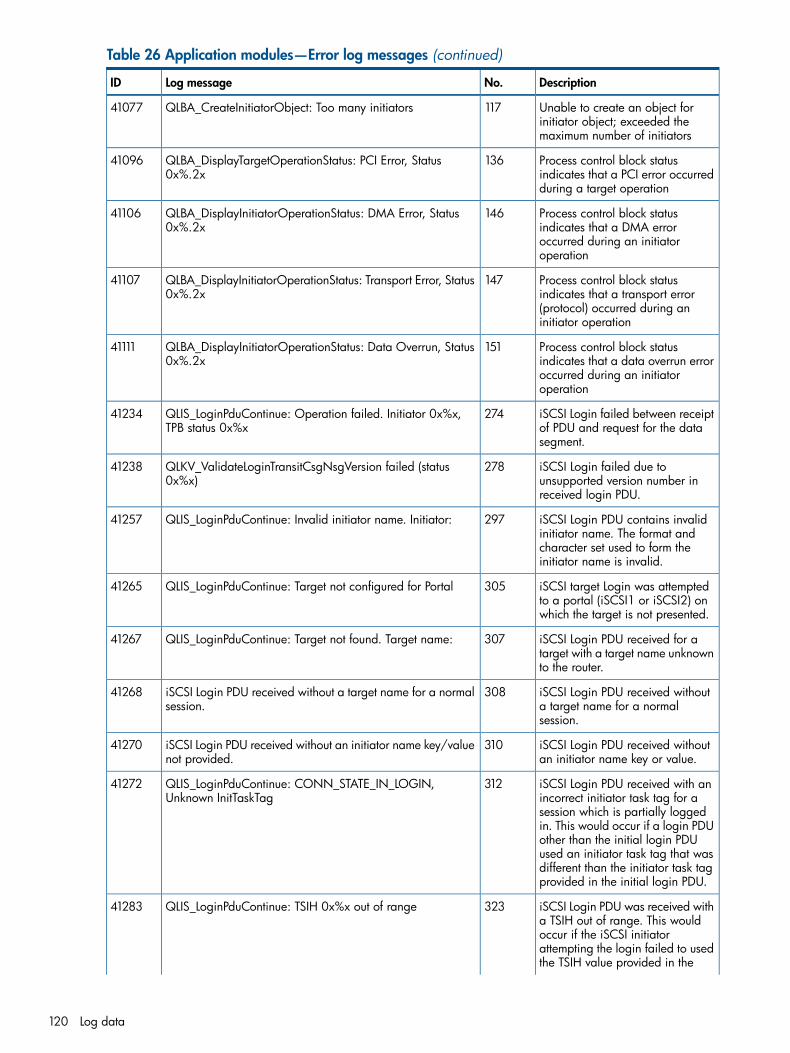
Table 26 Application modules—Error log messages (continued)
DescriptionNo.Log messageID
Unable to create an object forinitiator object; exceeded themaximum number of initiators
117QLBA_CreateInitiatorObject: Too many initiators41077
Process control block statusindicates that a PCI error occurredduring a target operation
136QLBA_DisplayTargetOperationStatus: PCI Error, Status0x%.2x
41096
Process control block statusindicates that a DMA error
146QLBA_DisplayInitiatorOperationStatus: DMA Error, Status0x%.2x
41106
occurred during an initiatoroperation
Process control block statusindicates that a transport error
147QLBA_DisplayInitiatorOperationStatus: Transport Error, Status0x%.2x
41107
(protocol) occurred during aninitiator operation
Process control block statusindicates that a data overrun error
151QLBA_DisplayInitiatorOperationStatus: Data Overrun, Status0x%.2x
41111
occurred during an initiatoroperation
iSCSI Login failed between receiptof PDU and request for the datasegment.
274QLIS_LoginPduContinue: Operation failed. Initiator 0x%x,TPB status 0x%x
41234
iSCSI Login failed due tounsupported version number inreceived login PDU.
278QLKV_ValidateLoginTransitCsgNsgVersion failed (status0x%x)
41238
iSCSI Login PDU contains invalidinitiator name. The format and
297QLIS_LoginPduContinue: Invalid initiator name. Initiator:41257
character set used to form theinitiator name is invalid.
iSCSI target Login was attemptedto a portal (iSCSI1 or iSCSI2) onwhich the target is not presented.
305QLIS_LoginPduContinue: Target not configured for Portal41265
iSCSI Login PDU received for atarget with a target name unknownto the router.
307QLIS_LoginPduContinue: Target not found. Target name:41267
iSCSI Login PDU received withouta target name for a normalsession.
308iSCSI Login PDU received without a target name for a normalsession.
41268
iSCSI Login PDU received withoutan initiator name key or value.
310iSCSI Login PDU received without an initiator name key/valuenot provided.
41270
iSCSI Login PDU received with anincorrect initiator task tag for a
312QLIS_LoginPduContinue: CONN_STATE_IN_LOGIN,Unknown InitTaskTag
41272
session which is partially loggedin. This would occur if a login PDUother than the initial login PDUused an initiator task tag that wasdifferent than the initiator task tagprovided in the initial login PDU.
iSCSI Login PDU was received witha TSIH out of range. This would
323QLIS_LoginPduContinue: TSIH 0x%x out of range41283
occur if the iSCSI initiatorattempting the login failed to usedthe TSIH value provided in the
120 Log data
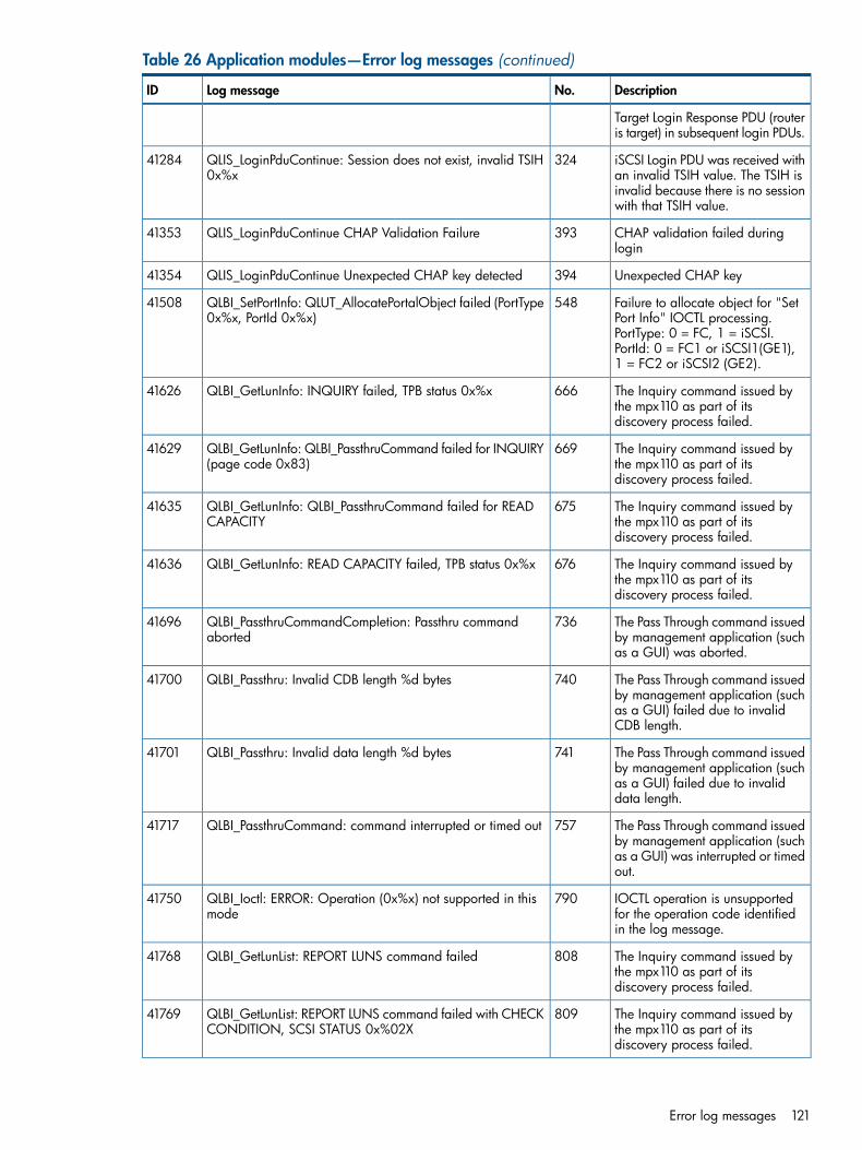
Table 26 Application modules—Error log messages (continued)
DescriptionNo.Log messageID
Target Login Response PDU (routeris target) in subsequent login PDUs.
iSCSI Login PDU was received withan invalid TSIH value. The TSIH is
324QLIS_LoginPduContinue: Session does not exist, invalid TSIH0x%x
41284
invalid because there is no sessionwith that TSIH value.
CHAP validation failed duringlogin
393QLIS_LoginPduContinue CHAP Validation Failure41353
Unexpected CHAP key394QLIS_LoginPduContinue Unexpected CHAP key detected41354
Failure to allocate object for "SetPort Info" IOCTL processing.
548QLBI_SetPortInfo: QLUT_AllocatePortalObject failed (PortType0x%x, PortId 0x%x)
41508
PortType: 0 = FC, 1 = iSCSI.PortId: 0 = FC1 or iSCSI1(GE1),1 = FC2 or iSCSI2 (GE2).
The Inquiry command issued bythe mpx110 as part of itsdiscovery process failed.
666QLBI_GetLunInfo: INQUIRY failed, TPB status 0x%x41626
The Inquiry command issued bythe mpx110 as part of itsdiscovery process failed.
669QLBI_GetLunInfo: QLBI_PassthruCommand failed for INQUIRY(page code 0x83)
41629
The Inquiry command issued bythe mpx110 as part of itsdiscovery process failed.
675QLBI_GetLunInfo: QLBI_PassthruCommand failed for READCAPACITY
41635
The Inquiry command issued bythe mpx110 as part of itsdiscovery process failed.
676QLBI_GetLunInfo: READ CAPACITY failed, TPB status 0x%x41636
The Pass Through command issuedby management application (suchas a GUI) was aborted.
736QLBI_PassthruCommandCompletion: Passthru commandaborted
41696
The Pass Through command issuedby management application (such
740QLBI_Passthru: Invalid CDB length %d bytes41700
as a GUI) failed due to invalidCDB length.
The Pass Through command issuedby management application (such
741QLBI_Passthru: Invalid data length %d bytes41701
as a GUI) failed due to invaliddata length.
The Pass Through command issuedby management application (such
757QLBI_PassthruCommand: command interrupted or timed out41717
as a GUI) was interrupted or timedout.
IOCTL operation is unsupportedfor the operation code identifiedin the log message.
790QLBI_Ioctl: ERROR: Operation (0x%x) not supported in thismode
41750
The Inquiry command issued bythe mpx110 as part of itsdiscovery process failed.
808QLBI_GetLunList: REPORT LUNS command failed41768
The Inquiry command issued bythe mpx110 as part of itsdiscovery process failed.
809QLBI_GetLunList: REPORT LUNS command failed with CHECKCONDITION, SCSI STATUS 0x%02X
41769
Error log messages 121

Table 26 Application modules—Error log messages (continued)
DescriptionNo.Log messageID
Failed to allocate LUN object: outof resources.
811QLBI_GetLunList: LUN allocation failed for LunId %d41771
Failed to allocate LUN object: outof resources.
1034QLFC_Login: VpIndex (%d) out of range41994
Login attempted using FibreChannel VP index that has not
1035QLFC_Login: VP Index 0x%x not configured41995
been configured. Operationattempted on an unconfigured VP.
Attempting login but Fibre Channelconnection cannot be opened.
1042QLFC_Login: Can't open connection42002
Attempting logout of device forwhich there is no active path(WWPN not found).
1064QLFC_Logout: No active path to device. WWPN:%.2X%.2X%.2X%.2X%.2X%.2X%.2X%.2X
42024
Logout attempted using FibreChannel VP index which has not
1067QLFC_Logout: VP Index 0x%x not configured42027
been configured. Operationattempted on an unconfigured VP.
Event notification: Fibre Channelprocessor encountered a system
1108QLFC_HandleTeb: System Error42068
error (unrecoverable firmwareerror).
Event notification: Fibre Channeldriver encountered a fatal error.
1109QLFC_HandleTeb: Driver Fatal Error42069
Event notification: Fibre Channelport logged out.
1112QLFC_HandleTeb: FC Logout.42072
Failed to allocate object for iSCSIsession: out of session resources.
1282QLIS_AllocateSessionObject: Out of session resources.42242
Received an iSCSI PDU with aduplicate CmdSN. Command PDUwill be dropped.
1292QLIS_EnqueueiScsiPdu: Duplicate PDU, CmdSN %d (0x%x),dropping it.
42252
Unable to allocate iSCSI initiatorobject while initiating a session.
1298QLIS_InstantiateSession: Can't add Initiator to the database42258
Exceeded the number of iSCSIhosts allowed to connect tompx100
1299#%d: QLIS_InstantiateSession: Maximum number (%d) ofallowed hosts already logged in
42259
Failed to execute iSCSI commandPDU due to its CmdSN being out
1444QLIS_ProcessStartTrb: [%d] CmdSN %ld is out of range(%ld—%ld), Cdb[0] 0x%02X, DataXferLen 0x%x.
42404
of range. Log message providesthe incorrect CmdSN, the validCmdSN range, the first byte of theCDB, and the length of the data.
Event notification: iSCSI driverencountered a fatal error.
1688QLIS_HandleTeb: Driver Fatal Error42648
Event notification: an IOCTLrequest was received to unload theiSCSI driver.
1689QLIS_HandleTeb: Unload Driver.42649
Event notification: attempt toconnect to the iSNS server failed.
1694QLIS_HandleTeb: iSNS Connection Failed42654
iSNS connection failed2052QLSC_CollectBUVUIO: Allocation of DSD failed43012
122 Log data

Table 26 Application modules—Error log messages (continued)
DescriptionNo.Log messageID
Break up I/O DSD allocationfailed
2053QLSC_CollectBUVUIORecover: Allocation of DSD failed43013
Break up I/O recover DSDallocation failed
2305QLUT_AllocateTpbExtension: TPB allocation failed43265
Data buffer allocation failed(length %d) during tpb extensionallocation
2307QLUT_AllocateTpbExtension: Data buffer allocation failed(length %d)
43267
Allocation of DSD failed duringTpb extension allocation. Bufferlength %d
2308QLUT_AllocateTpbExtension: Alloc of DSD failed for bufferlen %d
43268
FCIP incoming frame: BUGCHECK:Trb (0x%p) ValidFlag (0x%x)Direction (0x%x
2309QLFCIP_IncomingFrame: BUGCHECK: Trb (0x%p) ValidFlag(0x%x) Direction (0x%x)
43269
FCIP incoming frame:GetFcipMapPortal failed
2310QLFCIP_IncomingFrame: GetFcipMapPortal failed43270
FCIP incoming frame: Got Statusaborted pTrb->pBufDescList[0]:%pTrb Direction:0x%x
2311QLFCIP_IncomingFrame: Got Status abortedpTrb->pBufDescList[0]:%p Trb Direction:0x%x
43271
FCIP system error2312QLFCIP_SystemError: System error43272
FCIP system error:QLOP_IssuePortEnable failed
2313QLFCIP_SystemError: QLOP_IssuePortEnable failed43273
FCIP handle Teb: Driver Fatal error2320QLFCIP_HandleTeb: Driver Fatal error43280
FCIP configure portal: Find portalobject failed for QLUT_TYPE_FC,PortId (%d)
2321QLFCIP_ConfigPortal: Find portal object failed forQLUT_TYPE_FC, PortId (%d)
43281
FCIP configure portal:QLFCIP_ConfigPortal: Invalid PortIdfor FCIP link PortID(%d)
2322QLFCIP_ConfigPortal: QLFCIP_ConfigPortal: Invalid PortIdfor FCIP link PortID(%d)
43282
FCIP allocate TRB pool: Allocationfailed (size 0x%x))
2323QLUT_AllocateFcipTrbPool: Allocation failed (size 0x%x))43283
FCIP Trb: Null portal object in maptable
2324QLUT_GetFcipTrb: Null portal object in map table43284
FCIP get TRB: Null portal object inmap table
2325QLUT_GetFcipTrb: Unable to get the Free Trb43285
FCIP get TRB: Duplicate allocationof FcipTrb (0x%p)
2326QLUT_GetFcipTrb: Duplicate allocation of FcipTrb (0x%p)43286
FCIP free TRB: Null portal objectin map table
2327QLUT_FreeFcipTrb: Null portal object in map table43287
FCIP free TRB: Duplicate Free ofFcipTrb (0x%p)
2328QLUT_FreeFcipTrb: Duplicate Free of FcipTrb (0x%p)43288
FCIP initialize buffer descriptorpool: memory allocation for
2329QLUT_InitializeFcipBufDescPool: Memory allocation forFCIP_BUF_EXT_DESC failed (size 0x%x)
43289
FCIP_BUF_EXT_DESC failed (size0x%x)
FCIP free data buffers: DuplicateFreeing of DataBuf (0x%p)
2336QLUT_FreeFcipDataBuffers: Duplicate Freeing of DataBuf(0x%p)
43296
Error log messages 123
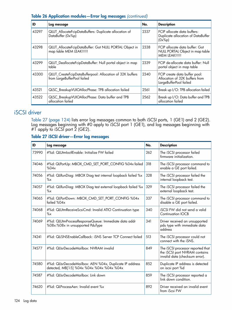
Table 26 Application modules—Error log messages (continued)
DescriptionNo.Log messageID
FCIP allocate data buffers:Duplicate allocation of DataBuffer(0x%p)
2337QLUT_AllocateFcipDataBuffers: Duplicate allocation ofDataBuffer (0x%p)
43297
FCIP allocate data buffer: GotNULL PORTAL Object in map tableMEM LEAK!!!!!
2338QLUT_AllocateFcipDataBuffer: Got NULL PORTAL Object inmap table MEM LEAK!!!!!
43298
FCIP de-allocate data buffer: Nullportal object in map table
2339QLUT_DeallocateFcipDataBuffer: Null portal object in maptable
43299
FCIP create data buffer pool:Allocation of 32K buffers fromLargeBufferPool failed
2340QLUT_CreateFcipDataBufferpool: Allocation of 32K buffersfrom LargeBufferPool failed
43300
Break up I/O: TPB allocation failed2561QLSC_BreakupVUIOAllocPhase: TPB allocation failed43521
Break up I/O: Data buffer and TPBallocation failed
2562QLSC_BreakupVUIOAllocPhase: Data buffer and TPBallocation failed
43522
iSCSI driverTable 27 (page 124) lists error log messages common to both iSCSI ports, 1 (GE1) and 2 (GE2).Log messages beginning with #0 apply to iSCSI port 1 (GE1), and log messages beginning with#1 apply to iSCSI port 2 (GE2).
Table 27 iSCSI driver—Error log messages
DescriptionNo.Log messageID
The iSCSI processor failedfirmware initialization.
262#%d: QLUtmIoctlEnable: Initialize FW failed73990
The iSCSI processor command toenable a GE port failed.
318#%d: QLPortUp: MBOX_CMD_SET_PORT_CONFIG %04x failed%04x
74046
The iSCSI processor failed theinternal loopback test.
328#%d: QLRunDiag: MBOX Diag test internal loopback failed %x%x
74056
The iSCSI processor failed theexternal loopback test.
329#%d: QLRunDiag: MBOX Diag test external loopback failed %x%x
74057
The iSCSI processor command todisable a GE port failed.
337#%d: QLPortDown: MBOX_CMD_SET_PORT_CONFIG %04xfailed %04x
74065
iSCSI FW did not send a validContinuation IOCB
340#%d: QLUtmReceiveScsiCmd: Invalid ATIO Continuation type%x
74068
Driver received an unsupportedpdu type with immediate dataaddress
341#%d: QLUtmProcessResponseQueue: Immediate data addr%08x:%08x in unsupported PduType
74069
The iSCSI processor could notconnect with the iSNS.
513#%d: QLiSNSEnableCallback: iSNS Server TCP Connect failed74241
The iSCSI processor reported thatthe iSCSI port NVRAM containsinvalid data (checksum error).
849#%d: QLIsrDecodeMailbox: NVRAM invalid74577
Duplicate IP address is detectedon iscsi port %d
852#%d: QLIsrDecodeMailbox: AEN %04x, Duplicate IP addressdetected, MB[1-5] %04x %04x %04x %04x %04x
74580
The iSCSI processor reported alink down condition.
859#%d: QLIsrDecodeMailbox: Link down74587
Driver received an invalid eventfrom iScsi FW
892#%d: QLProcessAen: Invalid event %x74620
124 Log data
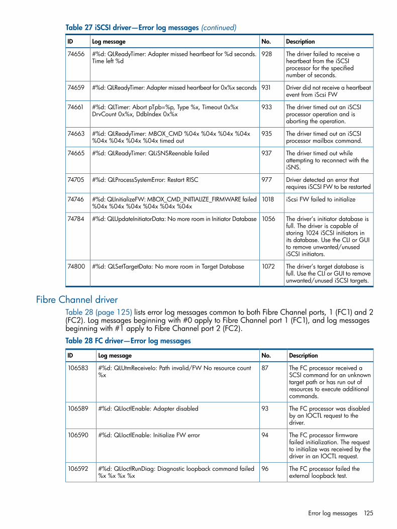
Table 27 iSCSI driver—Error log messages (continued)
DescriptionNo.Log messageID
The driver failed to receive aheartbeat from the iSCSI
928#%d: QLReadyTimer: Adapter missed heartbeat for %d seconds.Time left %d
74656
processor for the specifiednumber of seconds.
Driver did not receive a heartbeatevent from iScsi FW
931#%d: QLReadyTimer: Adapter missed heartbeat for 0x%x seconds74659
The driver timed out an iSCSIprocessor operation and isaborting the operation.
933#%d: QLTimer: Abort pTpb=%p, Type %x, Timeout 0x%xDrvCount 0x%x, DdbIndex 0x%x
74661
The driver timed out an iSCSIprocessor mailbox command.
935#%d: QLReadyTimer: MBOX_CMD %04x %04x %04x %04x%04x %04x %04x %04x timed out
74663
The driver timed out whileattempting to reconnect with theiSNS.
937#%d: QLReadyTimer: QLiSNSReenable failed74665
Driver detected an error thatrequires iSCSI FW to be restarted
977#%d: QLProcessSystemError: Restart RISC74705
iScsi FW failed to initialize1018#%d: QLInitializeFW: MBOX_CMD_INITIALIZE_FIRMWARE failed%04x %04x %04x %04x %04x %04x
74746
The driver’s initiator database isfull. The driver is capable of
1056#%d: QLUpdateInitiatorData: No more room in Initiator Database74784
storing 1024 iSCSI initiators inits database. Use the CLI or GUIto remove unwanted/unusediSCSI initiators.
The driver’s target database isfull. Use the CLI or GUI to removeunwanted/unused iSCSI targets.
1072#%d: QLSetTargetData: No more room in Target Database74800
Fibre Channel driverTable 28 (page 125) lists error log messages common to both Fibre Channel ports, 1 (FC1) and 2(FC2). Log messages beginning with #0 apply to Fibre Channel port 1 (FC1), and log messagesbeginning with #1 apply to Fibre Channel port 2 (FC2).
Table 28 FC driver—Error log messages
DescriptionNo.Log messageID
The FC processor received aSCSI command for an unknown
87#%d: QLUtmReceiveIo: Path invalid/FW No resource count%x
106583
target path or has run out ofresources to execute additionalcommands.
The FC processor was disabledby an IOCTL request to thedriver.
93#%d: QLIoctlEnable: Adapter disabled106589
The FC processor firmwarefailed initialization. The request
94#%d: QLIoctlEnable: Initialize FW error106590
to initialize was received by thedriver in an IOCTL request.
The FC processor failed theexternal loopback test.
96#%d: QLIoctlRunDiag: Diagnostic loopback command failed%x %x %x %x
106592
Error log messages 125
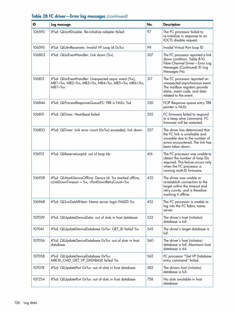
Table 28 FC driver—Error log messages (continued)
DescriptionNo.Log messageID
The FC processor failed tore-initialize in response to anIOCTL disable request.
97#%d: QLIoctlDisable: Re-initialize adapter failed106593
Invalid Virtual Port loop ID99#%d: QLUtmReceiveIo: Invalid VP Loop Id 0x%x106595
The FC processor reported a linkdown condition. Table B-10.
307#%d: QLIsrEventHandler: Link down (%x)106803
Fibre Channel Driver—Error LogMessages (Continued) ID LogMessages No.
The FC processor reported anunexpected asynchronous event.
317#%d: QLIsrEventHandler: Unexpected async event (%x),MB1=%x, MB2=%x, MB3=%x, MB4=%x, MB5=%x, MB6=%x,MB7=%x
106813
The mailbox registers providestatus, event code, and datarelated to the event.
FCIP Response queue entry TRBpointer is NULL
350#%d: QLProcessResponseQueueFS: TRB is NULL: %d106846
FC firmware failed to respondto a keep alive command. FCfirmware will be restarted.
355#%d: QLTimer: Heartbeat failed106851
The driver has determined thatthe FC link is unreliable and
357#%d: QLTimer: Link error count (0x%x) exceeded, link down106853
unusable due to the number oferrors encountered. The link hasbeen taken down.
The FC processor was unable toobtain the number of loop IDs
416#%d: QLReserveLoopId: out of loop Ids106912
required. This failure occurs onlywhen the FC processor isrunning multi-ID firmware.
The driver was unable tore-establish connection to the
432#%d: QLMarkDeviceOffline: Device Id: %x marked offline,cLinkDownTimeout = %x, cPortDownRetryCount=%x
106928
target within the timeout andretry counts, and is thereforemarking it offline.
The FC processor is unable tolog into the FC fabric nameserver.
452#%d: QLSnsGetAllNext: Name server login FAILED %x106948
The driver’s host (initiator)database is full.
533#%d: QLUpdateDeviceData: out of slots in host database107029
The driver’s target database isfull.
545#%d: QLUpdateDeviceDatabase 0x%x: GET_ID failed %x107041
The driver’s host (initiator)database is full. Maximum hostdatabase is 64.
560#%d: QLUpdateDeviceDatabase 0x%x: out of slots in hostdatabase
107056
FC processor “Get VP Databaseentry command" failed
562#%d: QLUpdateDeviceDatabase 0x%x:MBOX_CMD_GET_VP_DATABASE failed %x
107058
The drivers host (initiator)database is full.
582#%d: QLUpdatePort 0x%x: out of slots in host database107078
No slots available in hostdatabase
758#%d: QLUpdatePort 0x%x: out of slots in host database107254
126 Log data
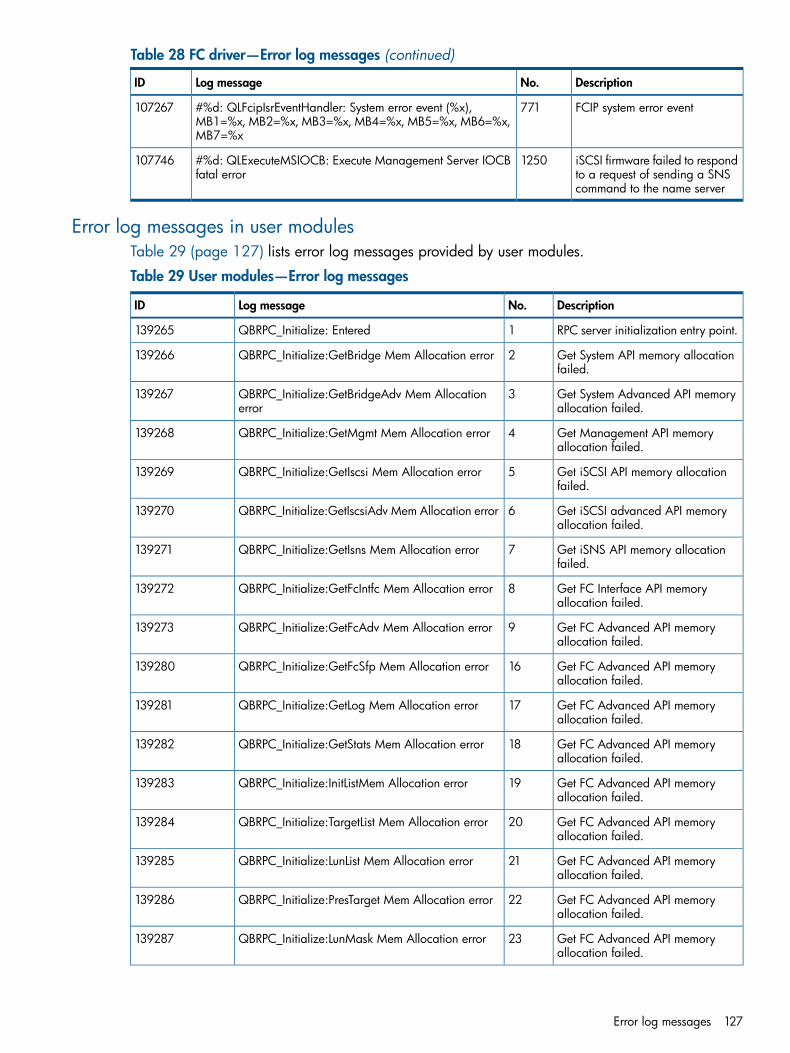
Table 28 FC driver—Error log messages (continued)
DescriptionNo.Log messageID
FCIP system error event771#%d: QLFcipIsrEventHandler: System error event (%x),MB1=%x, MB2=%x, MB3=%x, MB4=%x, MB5=%x, MB6=%x,MB7=%x
107267
iSCSI firmware failed to respondto a request of sending a SNScommand to the name server
1250#%d: QLExecuteMSIOCB: Execute Management Server IOCBfatal error
107746
Error log messages in user modulesTable 29 (page 127) lists error log messages provided by user modules.
Table 29 User modules—Error log messages
DescriptionNo.Log messageID
RPC server initialization entry point.1QBRPC_Initialize: Entered139265
Get System API memory allocationfailed.
2QBRPC_Initialize:GetBridge Mem Allocation error139266
Get System Advanced API memoryallocation failed.
3QBRPC_Initialize:GetBridgeAdv Mem Allocationerror
139267
Get Management API memoryallocation failed.
4QBRPC_Initialize:GetMgmt Mem Allocation error139268
Get iSCSI API memory allocationfailed.
5QBRPC_Initialize:GetIscsi Mem Allocation error139269
Get iSCSI advanced API memoryallocation failed.
6QBRPC_Initialize:GetIscsiAdv Mem Allocation error139270
Get iSNS API memory allocationfailed.
7QBRPC_Initialize:GetIsns Mem Allocation error139271
Get FC Interface API memoryallocation failed.
8QBRPC_Initialize:GetFcIntfc Mem Allocation error139272
Get FC Advanced API memoryallocation failed.
9QBRPC_Initialize:GetFcAdv Mem Allocation error139273
Get FC Advanced API memoryallocation failed.
16QBRPC_Initialize:GetFcSfp Mem Allocation error139280
Get FC Advanced API memoryallocation failed.
17QBRPC_Initialize:GetLog Mem Allocation error139281
Get FC Advanced API memoryallocation failed.
18QBRPC_Initialize:GetStats Mem Allocation error139282
Get FC Advanced API memoryallocation failed.
19QBRPC_Initialize:InitListMem Allocation error139283
Get FC Advanced API memoryallocation failed.
20QBRPC_Initialize:TargetList Mem Allocation error139284
Get FC Advanced API memoryallocation failed.
21QBRPC_Initialize:LunList Mem Allocation error139285
Get FC Advanced API memoryallocation failed.
22QBRPC_Initialize:PresTarget Mem Allocation error139286
Get FC Advanced API memoryallocation failed.
23QBRPC_Initialize:LunMask Mem Allocation error139287
Error log messages 127
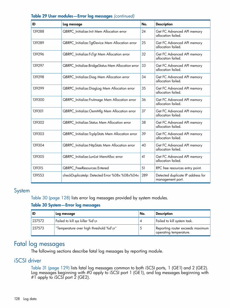
Table 29 User modules—Error log messages (continued)
DescriptionNo.Log messageID
Get FC Advanced API memoryallocation failed.
24QBRPC_Initialize:Init Mem Allocation error139288
Get FC Advanced API memoryallocation failed.
25QBRPC_Initialize:TgtDevice Mem Allocation error139289
Get FC Advanced API memoryallocation failed.
32QBRPC_Initialize:FcTgt Mem Allocation error139296
Get FC Advanced API memoryallocation failed.
33QBRPC_Initialize:BridgeStatus Mem Allocation error139297
Get FC Advanced API memoryallocation failed.
34QBRPC_Initialize:Diag Mem Allocation error139298
Get FC Advanced API memoryallocation failed.
35QBRPC_Initialize:DiagLog Mem Allocation error139299
Get FC Advanced API memoryallocation failed.
36QBRPC_Initialize:FruImage Mem Allocation error139300
Get FC Advanced API memoryallocation failed.
37QBRPC_Initialize:OemMfg Mem Allocation error139301
Get FC Advanced API memoryallocation failed.
38QBRPC_Initialize:Status Mem Allocation error139302
Get FC Advanced API memoryallocation failed.
39QBRPC_Initialize:TcpIpStats Mem Allocation error139303
Get FC Advanced API memoryallocation failed.
40QBRPC_Initialize:NtpStats Mem Allocation error139304
Get FC Advanced API memoryallocation failed.
41QBRPC_Initialize:LunList MemAlloc error139305
RPC free resources entry point.51QBRPC_FreeResources:Entered139315
Detected duplicate IP address formanagement port.
289checkDuplicateIp: Detected Error %08x %08x%04x139553
SystemTable 30 (page 128) lists error log messages provided by system modules.
Table 30 System—Error log messages
DescriptionNo.Log messageID
Failed to kill system task.4Failed to kill sys killer %d\n237572
Reporting router exceeds maximumoperating temperature.
5"Temperature over high threshold %d\n"237573
Fatal log messagesThe following sections describe fatal log messages by reporting module.
iSCSI driverTable 31 (page 129) lists fatal log messages common to both iSCSI ports, 1 (GE1) and 2 (GE2).Log messages beginning with #0 apply to iSCSI port 1 (GE1), and log messages beginning with#1 apply to iSCSI port 2 (GE2).
128 Log data

Table 31 iSCSI driver—Fatal log messages
DescriptionNo.Log messageID
iSCSI processor SRAM testfailed.
20#%d: qlutm_init: Diagnostic failed, invalid SRAM69652
iSCSI processor faileddiagnostic reboot.
21#%d: qlutm_init: Diagnostic failed, fail reboot69653
iSCSI processor failed NVRAMdiagnostic.
22#%d: qlutm_init: Diagnostic failed, invalid NVRAM69654
iSCSI processor failed DRAMdiagnostic.
23#%d: qlutm_init: Diagnostic failed, invalid DRAM69655
iSCSI processor failed to returndiagnostic results.
24#%d: qlutm_init: Failed to return diagnostic result to Bridge69656
Response queue entry containsan invalid handle.
309#%d: QLUtmProcessResponseQueue: Invalid handle %xEntryType %x
69941
Set NVRAM reboot timer failed.319#%d: QLSetNvram: QLRebootTimer failed AF %x RS %xTime %d
69951
Port disable reboot timer failed.332#%d: QLDisable: QLRebootTimer failed AF %x RS %x Time%d
69964
Port enable reboot timer failed.334#%d: QLEnable: QLRebootTimer failed AF %x RS %x Time%d
69966
iSNS response contains aninvalid handle.
592#%d: QLProcSrblessiSNSResponse: Invalid handle %x70224
Start iSCSI processor failed.768#%d: QLInitializeDevice: QLStartAdapter failed70400
iSCSI processor firmwareinitialization failed.
785#%d: QLInitializeAdapter: QLInitializeFW failed70417
iSCSI processor port fatal error.800#%d: QLDoInterruptServiceRoutine: PortFatal interrupt.PortFatalErrorStatus %08x CSR %08x AS %x AF %x
70432
Start iSCSI processor reboottimer failed.
816#%d: QLStartAdapter: QLRebootTimer failed AF %x RS %xTime %d
70448
iSCSI processor fatal systemerror.
857#%d: QLIsrDecodeMailbox: System Error 8002 MB[1-7]%04x %04x %04x %04x %04x %04x %04x
70489
Response queue invalid handlefor ET pass-through.
867#%d: QLProcessResponseQueue: Invalid handle forET_PASSTHROUGH_STATUS
70499
Response queue invalid entrytype.
869#%d: QLProcessResponseQueue: Invalid entry type inresponse queue %x
70501
Response queue invalid handlefor specified entry type.
870#%d: QLProcessResponseQueue: Invalid handle %xEntryType %x
70502
Asynchronous event forunknown event type.
892#%d: QLProcessAen: Invalid event %x70524
Reboot timer failed.912#%d: QLRebootTimer: Reboot failed!70544
iSCSI driver missed iSCSIprocessor heartbeat. iSCSIprocessor rebooted.
931#%d: QLReadyTimer: Adapter missed heartbeat for 0x%xseconds. Rebooting
70563
iSCSI processor failed tocomplete operation beforetimeout.
932#%d: QLReadyTimer: Abort pTpb=%p failed, DrvCount0x%x
70564
iSCSI processor system errorrestart.
977#%d: QLProcessSystemError: Restart RISC70609
Fatal log messages 129
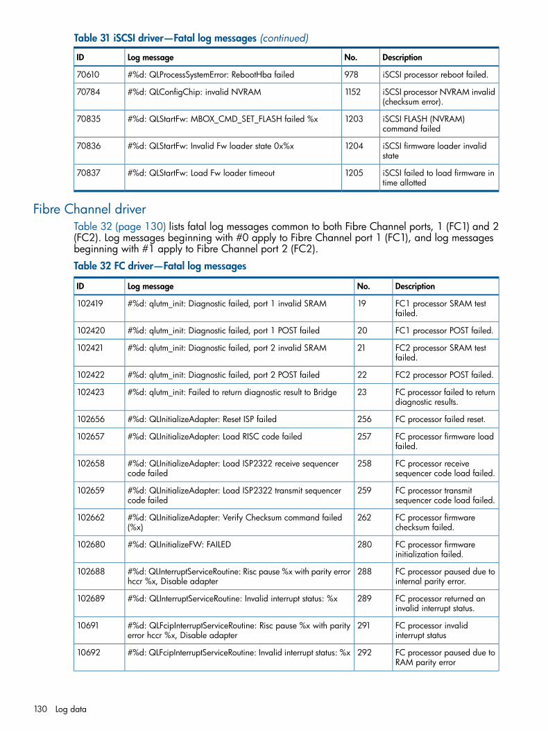
Table 31 iSCSI driver—Fatal log messages (continued)
DescriptionNo.Log messageID
iSCSI processor reboot failed.978#%d: QLProcessSystemError: RebootHba failed70610
iSCSI processor NVRAM invalid(checksum error).
1152#%d: QLConfigChip: invalid NVRAM70784
iSCSI FLASH (NVRAM)command failed
1203#%d: QLStartFw: MBOX_CMD_SET_FLASH failed %x70835
iSCSI firmware loader invalidstate
1204#%d: QLStartFw: Invalid Fw loader state 0x%x70836
iSCSI failed to load firmware intime allotted
1205#%d: QLStartFw: Load Fw loader timeout70837
Fibre Channel driverTable 32 (page 130) lists fatal log messages common to both Fibre Channel ports, 1 (FC1) and 2(FC2). Log messages beginning with #0 apply to Fibre Channel port 1 (FC1), and log messagesbeginning with #1 apply to Fibre Channel port 2 (FC2).
Table 32 FC driver—Fatal log messages
DescriptionNo.Log messageID
FC1 processor SRAM testfailed.
19#%d: qlutm_init: Diagnostic failed, port 1 invalid SRAM102419
FC1 processor POST failed.20#%d: qlutm_init: Diagnostic failed, port 1 POST failed102420
FC2 processor SRAM testfailed.
21#%d: qlutm_init: Diagnostic failed, port 2 invalid SRAM102421
FC2 processor POST failed.22#%d: qlutm_init: Diagnostic failed, port 2 POST failed102422
FC processor failed to returndiagnostic results.
23#%d: qlutm_init: Failed to return diagnostic result to Bridge102423
FC processor failed reset.256#%d: QLInitializeAdapter: Reset ISP failed102656
FC processor firmware loadfailed.
257#%d: QLInitializeAdapter: Load RISC code failed102657
FC processor receivesequencer code load failed.
258#%d: QLInitializeAdapter: Load ISP2322 receive sequencercode failed
102658
FC processor transmitsequencer code load failed.
259#%d: QLInitializeAdapter: Load ISP2322 transmit sequencercode failed
102659
FC processor firmwarechecksum failed.
262#%d: QLInitializeAdapter: Verify Checksum command failed(%x)
102662
FC processor firmwareinitialization failed.
280#%d: QLInitializeFW: FAILED102680
FC processor paused due tointernal parity error.
288#%d: QLInterruptServiceRoutine: Risc pause %x with parity errorhccr %x, Disable adapter
102688
FC processor returned aninvalid interrupt status.
289#%d: QLInterruptServiceRoutine: Invalid interrupt status: %x102689
FC processor invalidinterrupt status
291#%d: QLFcipInterruptServiceRoutine: Risc pause %x with parityerror hccr %x, Disable adapter
10691
FC processor paused due toRAM parity error
292#%d: QLFcipInterruptServiceRoutine: Invalid interrupt status: %x10692
130 Log data

Table 32 FC driver—Fatal log messages (continued)
DescriptionNo.Log messageID
FC processor system error.316#%d: QLIsrEventHandler: System error event (%x), MB1=%x,MB2=%x, MB3=%x, MB4=%x, MB5=%x, MB6=%x, MB7=%x
102716
Response queue entrycontains an invalid handle.
346#%d: QLProcessResponseQueue: Invalid handle %x, type %x102746
FCIP-Response queue entrycontains an invalid buffertype
347#%d: QLProcessResponseQueueFS: Invalid buffer type: %x102747
FCIP-Response queue entrycontains an invalid entrytype
348#%d: QLProcessResponseQueueFS: Invalid EntryType (0x%x)102748
FCIP-Response queue entrycontains an invalid handle
349#%d: QLProcessResponseQueueFS: Invalid handle 0x%x, type0x%x
102749
FC processor external SRAMparity error count exceededlimit; FC port disabled.
352#%d: QLTimer: Ext Ram parity error exceed limit cnt 0x%x, limit0x%x, Disabled adapter
102752
FC processor heartbeatfailed.
355#%d: QLTimer: Heartbeat failed102755
FC processor beingrestarted.
400#%d: QLRestartRisc: restart RISC102800
TOE driverTable 33 (page 131) lists fatal log messages provided by the TOE driver.
Table 33 TOE driver—Fatal log messages
DescriptionNo.Log messageID
Encountered invalid parameters inTOE NVRAM.
17QL3022:ql3xxx_probe: Adapter eth#%d, InvalidNVRAM parameters
200721
TOE chip reset due to detection offatal error.
21QL3022:eth%x: Resetting chip. PortFatalErrStatusregister = 0x%x
200725
SystemTable 34 (page 131) lists fatal log messages provided by system modules.
Table 34 System—Fatal log messages
DescriptionNo.Log messageID
Uncorrectable memory error detected ataddress provided in log message.
1Memory monitor: Detected Uncorrectable Ecc%08lx system is rebooting in 5 secs\n
233473
Attempt to register the interrupt handlerfailed.
2Failed to register interrupt handler!\n233474
Failed class_simple_create system call frommemory monitor initialization routine.
3%s class_simple_create failed\n233475
Fatal log messages 131
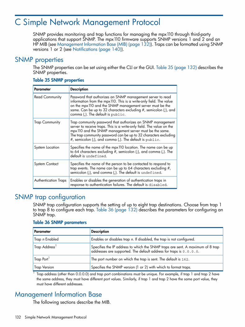
C Simple Network Management ProtocolSNMP provides monitoring and trap functions for managing the mpx110 through third-partyapplications that support SNMP. The mpx110 firmware supports SNMP versions 1 and 2 and anHP MIB (see Management Information Base (MIB) (page 132)). Traps can be formatted using SNMPversions 1 or 2 (see Notifications (page 140)).
SNMP propertiesThe SNMP properties can be set using either the CLI or the GUI. Table 35 (page 132) describes theSNMP properties.
Table 35 SNMP properties
DescriptionParameter
Password that authorizes an SNMP management server to readinformation from the mpx110. This is a write-only field. The value
Read Community
on the mpx110 and the SNMP management server must be thesame. Can be up to 32 characters excluding #, semicolon (;), andcomma (,). The default is public.
Trap community password that authorizes an SNMP managementserver to receive traps. This is a write-only field. The value on the
Trap Community
mpx110 and the SNMP management server must be the same.The trap community password can be up to 32 characters excluding#, semicolon (;), and comma (,). The default is public.
Specifies the name of the mpx110 location. The name can be upto 64 characters excluding #, semicolon (;), and comma (,). Thedefault is undefined.
System Location
Specifies the name of the person to be contacted to respond totrap events. The name can be up to 64 characters excluding #,semicolon (;), and comma (,). The default is undefined.
System Contact
Enables or disables the generation of authentication traps inresponse to authentication failures. The default is disabled.
Authentication Traps
SNMP trap configurationSNMP trap configuration supports the setting of up to eight trap destinations. Choose from trap 1to trap 8 to configure each trap. Table 36 (page 132) describes the parameters for configuring anSNMP trap.
Table 36 SNMP parameters
DescriptionParameter
Enables or disables trap n. If disabled, the trap is not configured.Trap n Enabled
Specifies the IP address to which the SNMP traps are sent. A maximum of 8 trapaddresses are supported. The default address for traps is 0.0.0.0.
Trap Address1
The port number on which the trap is sent. The default is 162.Trap Port1
Specifies the SNMP version (1 or 2) with which to format traps.Trap Version1 Trap address (other than 0.0.0.0) and trap port combinations must be unique. For example, if trap 1 and trap 2 havethe same address, they must have different port values. Similarly, if trap 1 and trap 2 have the same port value, theymust have different addresses.
Management Information BaseThe following sections describe the MIB.
132 Simple Network Management Protocol
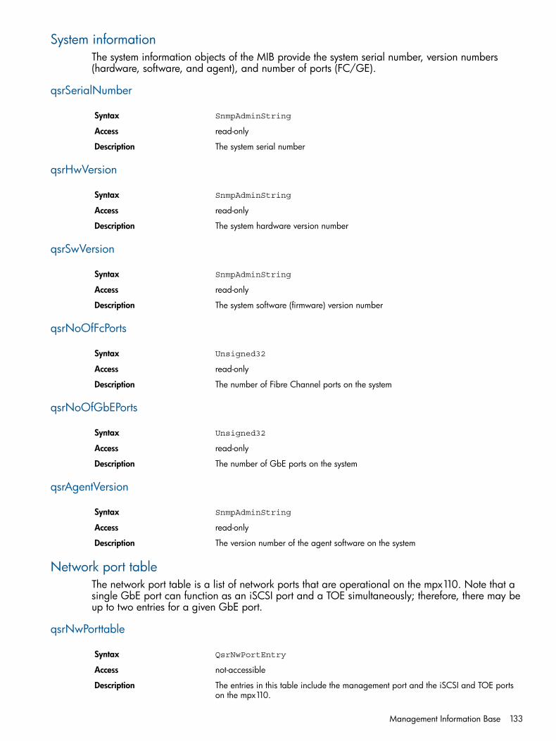
System informationThe system information objects of the MIB provide the system serial number, version numbers(hardware, software, and agent), and number of ports (FC/GE).
qsrSerialNumber
SnmpAdminStringSyntax
read-onlyAccess
The system serial numberDescription
qsrHwVersion
SnmpAdminStringSyntax
read-onlyAccess
The system hardware version numberDescription
qsrSwVersion
SnmpAdminStringSyntax
read-onlyAccess
The system software (firmware) version numberDescription
qsrNoOfFcPorts
Unsigned32Syntax
read-onlyAccess
The number of Fibre Channel ports on the systemDescription
qsrNoOfGbEPorts
Unsigned32Syntax
read-onlyAccess
The number of GbE ports on the systemDescription
qsrAgentVersion
SnmpAdminStringSyntax
read-onlyAccess
The version number of the agent software on the systemDescription
Network port tableThe network port table is a list of network ports that are operational on the mpx110. Note that asingle GbE port can function as an iSCSI port and a TOE simultaneously; therefore, there may beup to two entries for a given GbE port.
qsrNwPorttable
QsrNwPortEntrySyntax
not-accessibleAccess
The entries in this table include the management port and the iSCSI and TOE portson the mpx110.
Description
Management Information Base 133

qsrNwPortEntry
QsrNwPortEntrySyntax
not-accessibleAccess
Each entry (row) contains information about a specific network port.Description
QsrNwPortEntryA network port entry consists of the following sequence of objects:
QsrPortRoleqsrNwPortRole
unsigned32qsrNwPortIndex
INTEGERqsrNwPortAddressMode
InetAddressTypeqsrIPAddressType
InetAddressqsrIPAddress
InetAddressqsrNetMask
InetAddressqsrGateway
MacAddressqsrMacAddress
QsrLinkStatusqsrNwLinkStatus
QsrLinkRateqsrNwLinkRate
qsrNwPortRole
QsrPortRoleSyntax
not-accessibleAccess
The operational role of this port, such as a management port, an iSCSI port, or aTOE; a positive integer indexing each network port in a given role.
Description
qsrNwPortIndex
Unsigned32Syntax
not-accessibleAccess
A positive integer indexing each network port in a given roleDescription
qsrNwPortAddressMode
INTEGER 1 - Static 2 - DHCP 3 - Bootp 4 - RARPSyntax
read-onlyAccess
The method the port uses to obtain its IP addressDescription
qsrIPAddressType
InetAddressTypeSyntax
read-onlyAccess
The type of IP address, such as IPv4 or IPv6Description
134 Simple Network Management Protocol

qsrIPAddress
InetAddressSyntax
read-onlyAccess
The IP address of the portDescription
qsrNetMask
InetAddressSyntax
read-onlyAccess
The subnet mask of the portDescription
qsrGateway
InetAddressSyntax
read-onlyAccess
The gateway for this portDescription
qsrMacAddress
IMacAddressSyntax
read-onlyAccess
The MAC address for this portDescription
qstNwLinkStatus
QsrLinkStatusSyntax
read-onlyAccess
The operational link for this portDescription
qsrNwLinkRate
QsrLinkRateSyntax
read-onlyAccess
The operational speed for this portDescription
Fibre Channel port tableThe Fibre Channel port table is a list of the FC ports on the mpx110.
qsrFcPortTable
QsrFcPortEntrySyntax
not-accessibleAccess
A list of the FC ports on the mpx110. There are as many entries in this table as thereare FC ports on the mpx110.
Description
Management Information Base 135

qsrFcPortEntry
QsrFcPortEntrySyntax
not-accessibleAccess
Each entry (row) contains information about a specific FC port.Description
136 Simple Network Management Protocol
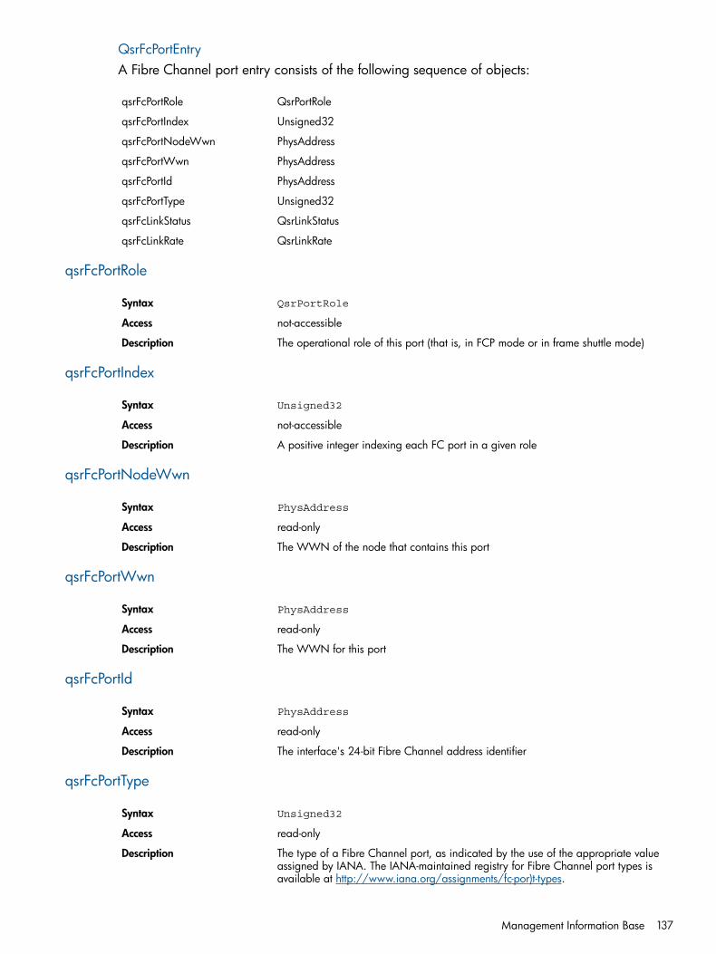
QsrFcPortEntryA Fibre Channel port entry consists of the following sequence of objects:
QsrPortRoleqsrFcPortRole
Unsigned32qsrFcPortIndex
PhysAddressqsrFcPortNodeWwn
PhysAddressqsrFcPortWwn
PhysAddressqsrFcPortId
Unsigned32qsrFcPortType
QsrLinkStatusqsrFcLinkStatus
QsrLinkRateqsrFcLinkRate
qsrFcPortRole
QsrPortRoleSyntax
not-accessibleAccess
The operational role of this port (that is, in FCP mode or in frame shuttle mode)Description
qsrFcPortIndex
Unsigned32Syntax
not-accessibleAccess
A positive integer indexing each FC port in a given roleDescription
qsrFcPortNodeWwn
PhysAddressSyntax
read-onlyAccess
The WWN of the node that contains this portDescription
qsrFcPortWwn
PhysAddressSyntax
read-onlyAccess
The WWN for this portDescription
qsrFcPortId
PhysAddressSyntax
read-onlyAccess
The interface's 24-bit Fibre Channel address identifierDescription
qsrFcPortType
Unsigned32Syntax
read-onlyAccess
The type of a Fibre Channel port, as indicated by the use of the appropriate valueassigned by IANA. The IANA-maintained registry for Fibre Channel port types isavailable at http://www.iana.org/assignments/fc-por)t-types.
Description
Management Information Base 137

qsrFcLinkStatus
QsrLinkStatusSyntax
read-onlyAccess
The current link status for this portDescription
qsrFcLinkRate
QsrLinkRateSyntax
read-onlyAccess
The current link rate for this portDescription
Sensor tableA list of all sensors on the mpx110.
qsrSensorTable
QsrSensorEntrySyntax
not-accessibleAccess
A list of all sensors on the mpx110. There are as many entries (rows) in this table asthere are sensors.
Description
qsrSensorEntry
QsrSensorEntrySyntax
not-accessibleAccess
Each entry (row) corresponds to a single sensor.Description
138 Simple Network Management Protocol

QsrSensorEntryA sensor entry consists of the following sequence of objects:
INTEGERqsrSensorType
Unsigned32qsrSensorIndex
INTEGERqsrSensorUnits
Integer32qsrSensorValue
Integer32qsrUpperThreshold
Integer32qsrLowerThreshold
INTEGERqsrSensorState
qsrSensorType
INTEGER temperature = 1Syntax
not-accessibleAccess
The type of data being measured by this sensorDescription
qsrSensorIndex
Unsigned32Syntax
not-accessibleAccess
A positive integer identifying each sensor of a given typeDescription
qsrSensorUnits
INTEGER celsius = 1Syntax
read-onlyAccess
The unit of measurement for the sensorDescription
qsrSensorValue
Integer32Syntax
read-onlyAccess
The current value of the sensorDescription
qsrUpperThreshold
Integer32Syntax
read-onlyAccess
The upper-level threshold for this sensorDescription
qsrLowerThreshold
Integer32Syntax
read-onlyAccess
The lower-level threshold for this sensorDescription
Management Information Base 139
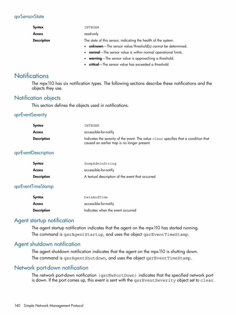
qsrSensorState
INTEGERSyntax
read-onlyAccess
The state of this sensor, indicating the health of the system.Description• unknown—The sensor value/threshold(s) cannot be determined.
• normal—The sensor value is within normal operational limits.
• warning—The sensor value is approaching a threshold.
• critical—The sensor value has exceeded a threshold.
NotificationsThe mpx110 has six notification types. The following sections describe these notifications and theobjects they use.
Notification objectsThis section defines the objects used in notifications.
qsrEventSeverity
INTEGERSyntax
accessible-for-notifyAccess
Indicates the severity of the event. The value clear specifies that a condition thatcaused an earlier trap is no longer present.
Description
qsrEventDescription
SnmpAdminStringSyntax
accessible-for-notifyAccess
A textual description of the event that occurredDescription
qsrEventTimeStamp
DateAndTimeSyntax
accessible-for-notifyAccess
Indicates when the event occurredDescription
Agent startup notificationThe agent startup notification indicates that the agent on the mpx110 has started running.The command is qsrAgentStartup, and uses the object qsrEventTimeStamp.
Agent shutdown notificationThe agent shutdown notification indicates that the agent on the mpx110 is shutting down.The command is qsrAgentShutdown, and uses the object qsrEventTimeStamp.
Network port-down notificationThe network port-down notification (qsrNwPortDown) indicates that the specified network portis down. If the port comes up, this event is sent with the qsrEventSeverity object set to clear.
140 Simple Network Management Protocol

qsrNwPortDown uses the following objects:
• qsrNwLinkStatus
• qsrEventTimeStamp
• qsrEventSeverity
Fibre Channel port-down notificationThe Fibre Channel port-down notification indicates that the specified Fibre Channel port is down.If the port comes up, this event is sent with the qsrEventSeverity object set to clear.qsrFcPortDown uses the following objects:
• qsrFcLinkStatus
• qsrEventTimeStamp
• qsrEventSeverity
Notifications 141

Sensor notificationThe sensor notification (qsrSensorNotification)indicates that the state of the specifiedsensor is not normal. Once the sensor returns to normal, this event is sent with theqsrEventSeverity object set to clear.qsrSensorNotification uses the following objects:
• qsrSensorValue
• qsrSensorState
• qsrEventTimeStamp
• qsrEventSeverity
Generic notificationThe generic notification (qsrGenericEvent) is used to report events other than the definedevent types. It provides a description object that identifies the event.qsrGenericEvent uses the following objects:
• qsrEventTimeStamp
• qsrEventSeverity
• qsrEventDescription
142 Simple Network Management Protocol
D Saving and restoring the mpx110 configurationThis appendix describes how to save and restore mpx110 configuration information. The mpx110configuration information is saved as a .bin or .tgz file, depending on the save method usedto restore the mpx110 persistent data. The mpx110 configuration information is saved and restoredusing the mpx110 manager GUI or mpx110 CLI commands.
NOTE: As with any important database, the mpx110 persistent data should be saved periodicallyto avoid data loss from hardware or software errors. It is also important to save the configurationinformation before replacing the mpx110.
Saving the mpx110 configurationUsing the mpx110 GUI to save configuration information allows you to save the file to any locationavailable to the server running the GUI.Using the mpx110 CLI command to save the configuration information places the file in thempx110’s FTP directory. You must then move the file using FTP from the mpx110.
Saving the configuration using the mpx110 GUITo save the configuration using the mpx110 GUI:1. Select File > Save FRU.
The Save FRU dialog box appears.2. Click Save.3. Enter a file name and select a location to save to.
NOTE: Do not change the Files of Type value.
4. Enter the password config, and then click OK.The configuration is saved to the selected location.
Saving the configuration using the mpx110 CLITo save the configuration using the mpx110 CLI:1. Log in to the mpx110 using a Telnet session to the management port or the console port.
Username: guest
Password: password
2. Enter the following command:mpx110> admin start
3. Enter config as the password.4. Enter the following command:
mpx110 (admin) #> fru save
FRU save completed. Configuration File isHP_StorageWorks_mpx110_FRU.bin. Please use FTP to extract the fileout from the System.
NOTE: The FRU creates a .bin file containing the mpx110’s persistent data, configuration,and LUN mappings. The file is stored in the mpx110's /var/ftp directory. You must thenFTP the .tar file from the mpx110.
5. Establish an FTP connection to the mpx110 management port and login:Username: ftp
Password: ftp
Saving the mpx110 configuration 143
6. Enter the following command to set the FTP transfer type to binary:ftp> bin
7. Enter the following command to retrieve the HP_StorageWorks_mpx110_FRU.bin file:ftp> get HP_StorageWorks_mpx110_FRU.bin
Restoring the mpx110 configurationUse the Full Configuration Restore option to fully restore the mpx110 configuration. The restoredconfiguration takes effect after the mpx110 is rebooted.
NOTE: Always use the Full Configuration Restore option with the mpx110.
Restoring the configuration using the mpx110 GUITo restore the configuration using the mpx110 GUI:1. Select File > Restore FRU.
The Restore FRU dialog box appears.2. Click Browse and select the appropriate file name to restore.3. Select Full Configuration Restore or Partial Restore (Mappings).4. Click Start.
The Security Check dialog box appears.5. Enter the password config, and then click OK.6. Reboot the system for the configuration to take effect.
Restoring the configuration using the mpx110 CLITo restore the configuration using the mpx110 CLI:1. Establish an FTP connection to the mpx110 management port and login:
Username: ftp
Password: ftp
2. Enter the following command to set the FTP transfer type to binary:ftp> bin
3. Enter the following command to move the HP_StorageWorks_mpx110_FRU.bin file ontothe FTP:ftp> put HP_StorageWorks_mpx110_FRU.bin
4. Log in to the mpx110 using a Telnet session to the management port or console port:Username: guest
Password: password
5. Enter the following command:mpx110> admin start
6. Enter config as the password.7. Enter the following command:
mpx110 (admin) #> fru restore
A list of attributes with formatting and current values will follow.Enter a new value or simply press the ENTER key to accept the currentvalue. If you wish to terminate this process before reaching theend of the list press 'q' or 'Q' and the ENTER key to do so. Typeof restore (0=full, 1=mappings only) [full]
FRU restore completed.
8. Reboot the system for the configuration to take effect.
144 Saving and restoring the mpx110 configuration

E Regulatory compliance and safetyThis appendix contains regulatory compliance and safety information for the mpx110.
Regulatory compliance
Federal Communications Commission notice for Class A equipmentThis equipment has been tested and found to comply with the limits for a Class A digital device,pursuant to Part 15 of the FCC Rules. These limits are designed to provide reasonable protectionagainst harmful interference when the equipment is operated in a commercial environment. Thisequipment generates, uses and can radiate radio frequency energy and, if not installed and usedin accordance with the instruction manual, may cause harmful interference to radio communications.Operation of this equipment in a residential area is likely to cause harmful interference, in whichcase the user will be required to correct the interference at his own expense. The end user of thisproduct should be aware that any changes or modifications made to this equipment without theapproval of Hewlett-Packard could result in the product not meeting the Class A limits, in whichcase the FCC could void the user’s authority to operate the equipment.
Declaration of conformity for products marked with the FCC logo, United States onlyThis device complies with Part 15 of the FCC Rules. Operation is subject to the following twoconditions: (1) this device may not cause harmful interference, and (2) this device must accept anyinterference received, including interference that may cause undesired operation.For questions regarding your product, visit http://www.hp.com/.For questions regarding this FCC declaration, contact us by mail or telephone:• Hewlett-Packard Company
P.O. Box 692000, Mailstop 510101Houston, TX 77269–2000
• 1–281–514–3333To identify this product, refer to the part, Regulatory Model Number, or product number found onthe product.
ModificationsThe FCC requires the user to be notified that any changes or modifications made to this devicethat are not expressly approved by Hewlett-Packard Company my void the user’s authority tooperate the equipment.
CablesConnections to this device must be made with shielded cables with metallic RFI/EMI connectorhoods in order to maintain compliance with FCC Rules and Regulations.
Regulatory compliance identification numbersFor the purpose of regulatory compliance certifications and identification, your product has beenassigned a unique Regulatory Model Number. The RMN can be found on the product nameplatelabel, along with all required approval markings and information. When requesting complianceinformation for this product, always refer to this RMN. The Regulatory Model Number should notbe confused with the marketing name or model number of the product.
Laser deviceAll HP systems equipped with a laser device comply with safety standards, including IEC 825.With specific regard to the laser, the equipment complies with laser product performance standardsset by government agencies as a Class 1 laser product. The product does not emit hazardous light.
Regulatory compliance 145
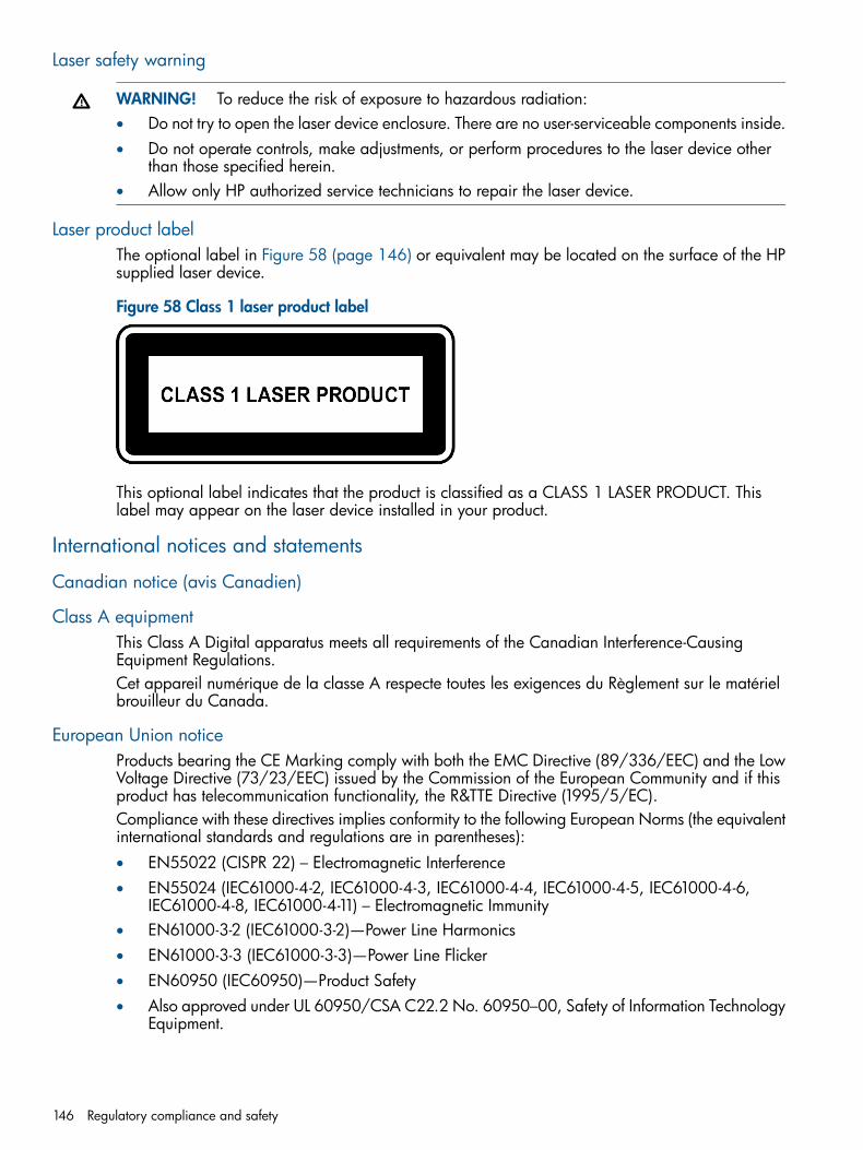
Laser safety warning
WARNING! To reduce the risk of exposure to hazardous radiation:• Do not try to open the laser device enclosure. There are no user-serviceable components inside.• Do not operate controls, make adjustments, or perform procedures to the laser device other
than those specified herein.• Allow only HP authorized service technicians to repair the laser device.
Laser product labelThe optional label in Figure 58 (page 146) or equivalent may be located on the surface of the HPsupplied laser device.
Figure 58 Class 1 laser product label
This optional label indicates that the product is classified as a CLASS 1 LASER PRODUCT. Thislabel may appear on the laser device installed in your product.
International notices and statements
Canadian notice (avis Canadien)
Class A equipmentThis Class A Digital apparatus meets all requirements of the Canadian Interference-CausingEquipment Regulations.Cet appareil numérique de la classe A respecte toutes les exigences du Règlement sur le matérielbrouilleur du Canada.
European Union noticeProducts bearing the CE Marking comply with both the EMC Directive (89/336/EEC) and the LowVoltage Directive (73/23/EEC) issued by the Commission of the European Community and if thisproduct has telecommunication functionality, the R&TTE Directive (1995/5/EC).Compliance with these directives implies conformity to the following European Norms (the equivalentinternational standards and regulations are in parentheses):• EN55022 (CISPR 22) – Electromagnetic Interference• EN55024 (IEC61000-4-2, IEC61000-4-3, IEC61000-4-4, IEC61000-4-5, IEC61000-4-6,
IEC61000-4-8, IEC61000-4-11) – Electromagnetic Immunity• EN61000-3-2 (IEC61000-3-2)—Power Line Harmonics• EN61000-3-3 (IEC61000-3-3)—Power Line Flicker• EN60950 (IEC60950)—Product Safety• Also approved under UL 60950/CSA C22.2 No. 60950–00, Safety of Information Technology
Equipment.
146 Regulatory compliance and safety

BSMI notice
Japanese notice
Korean notice
Safety
Battery replacement noticeYour switch is equipped with a lithium manganese dioxide, a vanadium pentoxide, or an alkalineinternal battery or battery pack. There is a danger of explosion and risk of personal injury if thebattery is incorrectly replaced or mistreated. Replacement is to be done by an HP authorized
Safety 147

service provider using the HP spare part designated for this product. For more information aboutbattery replacement or proper disposal, contact an HP authorized service provider.
WARNING! Your switch contains an internal lithium manganese dioxide, a vanadium pentoxide,or an alkaline battery pack. There is risk of fire and burns if the battery pack is not properly handled.To reduce the risk of personal injury:• Do not attempt to recharge the battery.• Do not expose to temperatures higher than 60ºC.• Do not disassemble, crush, puncture, short external contacts, or dispose of in fire or water.• Replace only with the HP spare part designated for this product.
Batteries, battery packs, and accumulators should not be disposed of together with the generalhousehold waste. To forward them to recycling or proper disposal, please use the public collectionsystem or return them to HP, an authorized HP Partner, or their agents.For more information about battery replacement or proper disposal, contact an HP authorizedreseller or service provider.
Taiwan battery recycling noticeThe Taiwan EPA requires dry battery manufacturing or importing firms in accordance with Article15 of the Waste Disposal Act to indicate the recovery marks on the batteries used in sales,giveaway, or promotion. Contact a qualified Taiwanese recycler for proper battery disposal.
Power cordsThe power cord set must meet the requirements for use in the country where the product waspurchased. If the product is to be used in another country, purchase a power cord that is approvedfor use in that country.The power cord must be rated for the product and for the voltage and current marked on theproduct electrical ratings label. The voltage and current rating of the cord should be greater thanthe voltage and current rating marked on the product. In addition, the diameter of the wire mustbe a minimum of 1.00 mm2 or 18 AWG, and the length of the cord must be between 1.8 m, (6ft) and 3.6 m (12 ft). If you have questions about the type of power cord to use, contact an HPauthorized service provider.
NOTE: Route power cords so that they will not be walked on and cannot be pinched by itemsplaced upon or against them. Pay particular attention to the plug, electrical outlet, and the pointwhere the cords exit from the product.
Japanese power cord statement
148 Regulatory compliance and safety

GlossaryC
CHAP Challenge Handshake Authentication ProtocolAn authentication technique for confirming the identity of one computer to another.
CmdSN Command sequence number
F
Fabric Connect Connecting a server or mpx110 Fibre Channel port to a Fibre Channel switch to access the EVAor XP Fibre Channel ports.
FC Fibre Channel technologySee also Fibre Channel.
FCIP Fibre Channel over Internet ProtocolFibre Channel A serial data transport infrastructure and protocol used to implement SANs. See also http://
www.fibrechannel.org/ and http://www.t11.org/.
G
GbE Gigabit EthernetPacket-based signaling technology that transmits data at throughput speeds of up to 1,000 Mb/sor 1 Gb/s.
H
high availability Refers to the availability of resources in a computer system if there are component failures in thesystem.
I
IEC International Electrotechnical Commissioninitiator A device that begins an iSCSI transaction by issuing a command to another device (the iSCSI
target), giving it a task to perform.IP Internet Protocol
The standard Internet protocol for moving packets of information from one computer to another.Commonly combined with TCP in the phrase TCP/IP.
IP SAN A SAN created using the iSCSI protocol to connect servers and storage over a GbE networkSee also iSCSI.
iSCSI Internet SCSIAn IP-based standard for linking data storage devices over a network and transferring data bycarrying SCSI commands over IP networks.
iSCSI CRC iSCSI cyclic redundancy checkA shortened cyclic code check used for error detection.
iSNS Internet Storage Name ServiceA protocol designed to facilitate the automated discovery, management, and configuration ofiSCSI and Fibre Channel devices on a TCP/IP network.
L
LIP Fibre Channel loop initialization procedure
149
M
MAC Media access addressMIB Management information basempx110 Serves as the FCIP data transport that transfers data to and from the local and remote storage
systems.MTU Maximum transmission unitMWS Minimum window size
N
NTP Network Time Protocol
P
PDU Power distribution unitPOST Power-on self-test
Q
QoS Quality of service. A traffic management feature.
R
RCS Remote copy setRPC Remote procedure callRTT Round-trip time
S
SAN Storage area network. An intelligent infrastructure that connects heterogeneous servers withshared, heterogeneous storage systems.
SCSI small computer system interfaceA parallel interface standard used to attach peripheral devices to computers.
switch An IP network communications device that routes packets (messages or fragments of messages)between nodes across virtual circuits.
T
target An iSCSI device that executes a command from an iSCSI initiator to perform some task.TCP Transmission Control Protocolteaming The concept of multiple network adapters working together as a single network adapter.
See also virtual network adapter.TOE TCP Offload Engine
Hardware that replaces a NIC and shifts TCP packet processing tasks from the server CPU tospecialized TCP processors on the network adapter or storage device.
V
virtual networkadapter
Multiple network adapters working together as a single network adapter; also referred to asteaming.
VLAN virtual local area networkA network of computers that behave as if they are connected to the same wire, even though theymay be physically located on different segments of a LAN.
VP Virtual port
150 Glossary

W
WWN World wide name. A unique identifier assigned to a Fibre Channel device.WWPN World wide port name
151

Index
AaccountsuserCLI, 80
Bbattery replacement notice, 147BSMI notice, 147
Ccables, 145Canadian notice, 146Class A equipment, 146CLI commandadmin, 84beacon, 85clear, 85date, 85FcipRoute, 85FRU, 88help, 89history, 90image, 91logout, 91password, 91ping, 92quit, 92reboot, 92reset factory, 93save, 94set, 94set fc, 95set MGMT, 96set ntp, 97set properties, 97set snmp, 98set system, 98show, 100show fciproutes, 101show logs, 102show memory, 102show mgmt, 103show NTP, 103show properties, 104show snmp, 105show stats, 106show system, 109show target, 111show targets, 110show vlan, 111traceroute, 112
connectivity rules, 21operating system, 21
conventionsdocument, 77
text symbols, 78
Ddeclaration of conformity, 145documentconventions, 77related documentation, 77
EEuropean Union notice, 146
FFC switch and fabric rulesseries, 22
FCC compliance notice, 145cables, 145declaration of conformity, 145modifications, 145
Hhardware requirementsinstallation, 33
helpobtaining, 78
HPstorage website, 78Subscriber's choice website, 78technical support, 78
IInstallation, 33installationhardware requirements, 33
installingmpx110 manager, 36
international notices, 146BSMI notice, 147Canadian notice, 146Class A equipment, 146European Union notice, 146Japanese notice, 147Korean notice, 147
Internet Storage Name Service see ISNS
JJapanese notice, 147Japanese power cord statement, 148
KKorean notice, 147
Llaser device, 145product label, 146safety warning, 146
LEDs
152 Index

system fault, 49
Mmodifications, 145mpx ManagerLinux, 37Windows server, 37
mpx110IP switch connection, 35managing, 50rack mount, 34SAN, 80server requirements, 36
mpx110 configurationsbacking up, 80
mpx110 Manager GUIstarting, 67
Nnetwork recommendations, 23
Ooperating systemconnectivity rules, 21
Ppower cords, 148pre-installation checklist, 34protocolinternet, 149iSCSI, 149ISNS, 149TCP/IP, 23
Rregulatory compliance, 145related documentation, 77rulesconfigurationEVA storage system rules, 21
SSafety, 147safetybattery replacement notice, 147Japanese power cord statement, 148power cords, 148Taiwan battery recycling notice, 148
SAN configurationsmpx110, 80
server requirementsmpx Manager, 36
Subscriber's choice, HP, 78switch supportmodel, 22versions, 22
symbols in text, 78
TTaiwan battery recycling notice, 148technical supportHP, 78
text symbols, 78
Uupgrading, 33
WwebsitesHP documentation, 78HP storage, 78HP Subscriber's choice, 78
153