hp openvms i/o user's reference manual
TRANSCRIPT

HP OpenVMS I/O User’s Reference ManualOpenVMS Version 8.4
HP Part Number: BA554-90018Published: June 2010

© Copyright 2010 Hewlett-Packard Development Company, L.P
Legal Notice
Confidential computer software. Valid license from HP required for possession, use or copying. Consistent with FAR 12.211 and 12.212, CommercialComputer Software, Computer Software Documentation, and Technical Data for Commercial Items are licensed to the U.S. Government undervendor's standard commercial license.
The information contained herein is subject to change without notice. The only warranties for HP products and services are set forth in the expresswarranty statements accompanying such products and services. Nothing herein should be construed as constituting an additional warranty. HPshall not be liable for technical or editorial errors or omissions contained herein.
Intel and Itanium are trademarks or registered trademarks of Intel Corporation or its subsidiaries in the United States and other countries.
The HP OpenVMS documentation set is available on CD-ROM.

Table of Contents
Preface..............................................................................................................................17Intended Audience................................................................................................................................17Document Structure..............................................................................................................................17Device Driver Support for OpenVMS Alpha and Integrity servers 64-Bit Addressing.......................17Related Documents...............................................................................................................................18Reader's Comments..............................................................................................................................18How to Order Additional Documentation...........................................................................................18Conventions..........................................................................................................................................18
1 ACP-QIO Interface.......................................................................................................211.1 ACP Functions and Encoding.........................................................................................................211.2 File Information Block.....................................................................................................................231.3 ACP Subfunctions...........................................................................................................................26
1.3.1 Directory Lookup....................................................................................................................261.3.1.1 Input Parameters.............................................................................................................271.3.1.2 Operation.........................................................................................................................281.3.1.3 Directory Entry Protection..............................................................................................29
1.3.2 Access......................................................................................................................................291.3.2.1 Input Parameters.............................................................................................................291.3.2.2 Operation.........................................................................................................................30
1.3.3 Extend......................................................................................................................................301.3.3.1 Input Parameters.............................................................................................................311.3.3.2 Operation.........................................................................................................................32
1.3.4 Truncate...................................................................................................................................321.3.4.1 Input Parameters.............................................................................................................321.3.4.2 Operation.........................................................................................................................33
1.3.5 Read/Write Attributes.............................................................................................................331.3.5.1 Input Parameters.............................................................................................................331.3.5.2 Attribute Descriptions.....................................................................................................37
1.4 ACP-QIO Record Attributes Area...................................................................................................391.5 ACP-QIO Attributes Statistics Block...............................................................................................411.6 Major Functions...............................................................................................................................42
1.6.1 Create File................................................................................................................................421.6.1.1 Input Parameters.............................................................................................................421.6.1.2 Disk ACP Operation........................................................................................................431.6.1.3 Directory Entry Creation.................................................................................................441.6.1.4 Magnetic Tape ACP Operation.......................................................................................44
1.6.2 Access File...............................................................................................................................441.6.2.1 Input Parameters.............................................................................................................441.6.2.2 Operation.........................................................................................................................45
1.6.3 Deaccess File............................................................................................................................451.6.3.1 Input Parameters.............................................................................................................461.6.3.2 Operation.........................................................................................................................46
1.6.4 Modify File..............................................................................................................................461.6.4.1 Input Parameters.............................................................................................................461.6.4.2 Operation.........................................................................................................................47
1.6.5 Delete File................................................................................................................................471.6.5.1 Operation.........................................................................................................................48
1.6.6 Movefile Subfunction..............................................................................................................481.6.6.1 Calling the Movefile Subfunction...................................................................................48
Table of Contents 3

1.6.6.1.1 Input Parameters.....................................................................................................481.6.7 Mount......................................................................................................................................511.6.8 ACP Control............................................................................................................................51
1.6.8.1 Input Parameters.............................................................................................................511.6.8.2 Magnetic Tape Control Functions...................................................................................521.6.8.3 Miscellaneous Disk Control Functions...........................................................................521.6.8.4 Disk Quotas.....................................................................................................................53
1.7 I/O Status Block...............................................................................................................................55
2 Disk Drivers...................................................................................................................572.1 Driver Features................................................................................................................................57
2.1.1 Data Check..............................................................................................................................572.1.2 Effects of a Failure During an I/O Write Operation................................................................582.1.3 Error Recovery.........................................................................................................................582.1.4 SCSI Disk Class Driver............................................................................................................592.1.5 Audio Extensions to the SCSI Disk Class Driver....................................................................59
2.2 Disk Driver Device Information......................................................................................................602.3 Disk Function Codes.......................................................................................................................60
2.3.1 Read.........................................................................................................................................632.3.2 Write........................................................................................................................................642.3.3 Sense Mode..............................................................................................................................652.3.4 Set Density...............................................................................................................................652.3.5 Search......................................................................................................................................652.3.6 Pack Acknowledge..................................................................................................................662.3.7 Unload.....................................................................................................................................662.3.8 Available..................................................................................................................................662.3.9 Seek..........................................................................................................................................662.3.10 Write Check...........................................................................................................................662.3.11 Audio Extensions...................................................................................................................67
2.3.11.1 $QIO Interface to Audio Functionality of the SCSI Disk Class Driver.........................682.3.11.2 Defining an Audio Control Block (AUCB)....................................................................692.3.11.3 Error Handling in Applications Using SCSI Audio Functions.....................................712.3.11.4 Using CD-ROM to Store Both Data and Audio Information........................................722.3.11.5 Programming Audio Applications................................................................................73
2.4 I/O Status Block...............................................................................................................................732.5 Disk Driver Programming Example................................................................................................73
3 Magnetic Tape Drivers................................................................................................813.1 HP Magnetic Tape Controllers and Drives.....................................................................................813.2 Magnetic Tape Driver Device Information......................................................................................813.3 Magnetic Tape Function Codes.......................................................................................................82
3.3.1 Read.........................................................................................................................................863.3.2 Write........................................................................................................................................873.3.3 Rewind....................................................................................................................................883.3.4 Skip File...................................................................................................................................883.3.5 Skip Record.............................................................................................................................89
3.3.5.1 Logical End-of-Volume (EOV) Detection........................................................................893.3.6 Write End-of-File.....................................................................................................................903.3.7 Rewind Offline........................................................................................................................903.3.8 Unload.....................................................................................................................................903.3.9 Sense Tape Mode.....................................................................................................................903.3.10 Set Mode................................................................................................................................913.3.11 Multiple Tape Density Support ............................................................................................93
4 Table of Contents

3.3.12 Data Security Erase................................................................................................................943.3.13 Modify...................................................................................................................................943.3.14 Pack Acknowledge................................................................................................................943.3.15 Available................................................................................................................................943.3.16 Flush......................................................................................................................................95
3.4 I/O Status Block...............................................................................................................................953.5 Magnetic Tape Drive Programming Examples...............................................................................95
4 Mailbox Driver...........................................................................................................1034.1 Mailbox Operations.......................................................................................................................103
4.1.1 Creating Mailboxes................................................................................................................1034.1.2 Deleting Mailboxes................................................................................................................1054.1.3 Mailbox Protection................................................................................................................1054.1.4 Mailbox Message Format......................................................................................................105
4.2 Mailbox Driver Device Information..............................................................................................1064.3 Mailbox Function Codes................................................................................................................106
4.3.1 Read.......................................................................................................................................1074.3.2 Write......................................................................................................................................1104.3.3 Write End-of-File Message....................................................................................................1114.3.4 Set Attention AST..................................................................................................................1124.3.5 Wait for Writer/Reader..........................................................................................................1144.3.6 Set Protection.........................................................................................................................1154.3.7 Get Mailbox Information.......................................................................................................115
4.4 I/O Status Block.............................................................................................................................1154.5 Mailbox Driver Programming Examples......................................................................................117
5 Terminal Driver...........................................................................................................1275.1 Terminal Driver Features...............................................................................................................127
5.1.1 Input Processing....................................................................................................................1275.1.1.1 Command-Line Editing and Command Recall.............................................................1275.1.1.2 Control Characters and Special Keys............................................................................1285.1.1.3 Read Verify....................................................................................................................1315.1.1.4 Escape and Control Sequences......................................................................................1315.1.1.5 Type-Ahead Feature......................................................................................................1325.1.1.6 Line Terminators...........................................................................................................1335.1.1.7 Special Operating Modes..............................................................................................133
5.1.2 Output Processing.................................................................................................................1335.1.2.1 Duplex Modes...............................................................................................................1335.1.2.2 Formatting of Output....................................................................................................1345.1.2.3 SET HOST Facility and Output Buffering.....................................................................134
5.1.3 Dialup Support......................................................................................................................1355.1.3.1 Modem Signal Control..................................................................................................1365.1.3.2 Hangup on Logging Out...............................................................................................1385.1.3.3 Preservation of a Process Across Hangups...................................................................139
5.1.4 Terminal/Mailbox Interaction................................................................................................1395.1.5 Autobaud Detection..............................................................................................................1405.1.6 Out-of-Band Control Character Handling............................................................................141
5.2 Terminal Driver Device Information.............................................................................................1415.2.1 Terminal Characteristics Categories......................................................................................146
5.3 Terminal Function Codes...............................................................................................................1475.3.1 Read.......................................................................................................................................147
5.3.1.1 Function Modifier Codes for Read QIO Functions.......................................................1485.3.1.2 Read Function Terminators...........................................................................................148
Table of Contents 5

5.3.1.3 Itemlist Read Operations...............................................................................................1495.3.1.4 Read Verify Function.....................................................................................................153
5.3.2 Write......................................................................................................................................1545.3.2.1 Function Modifier Codes for Write QIO Functions......................................................1545.3.2.2 Write Function Carriage Control...................................................................................155
5.3.3 Set Mode................................................................................................................................1565.3.3.1 Hangup Function Modifier...........................................................................................1595.3.3.2 Enable Ctrl/C AST and Enable Ctrl/Y AST Function Modifiers...................................1595.3.3.3 Set Modem Function Modifier......................................................................................1605.3.3.4 Loopback Function Modifier.........................................................................................1615.3.3.5 Enable Out-of-Band AST Function Modifier................................................................1615.3.3.6 Broadcast Function Modifier.........................................................................................163
5.3.4 LAT Port Driver QIO Interface..............................................................................................1635.3.4.1 LAT Port Types..............................................................................................................1645.3.4.2 LAT Port Driver Functions............................................................................................1645.3.4.3 Creating and Configuring LAT Entities........................................................................1655.3.4.4 Obtaining Information About LAT Entities..................................................................171
5.3.4.4.1 SENSEMODE Item Codes.....................................................................................1725.3.4.5 Programming Application Ports...................................................................................1835.3.4.6 Programming Application Services and Dedicated Ports............................................1845.3.4.7 Programming Forward Ports........................................................................................1855.3.4.8 Queue Change Notification ..........................................................................................1855.3.4.9 Hangup Notification.....................................................................................................1865.3.4.10 Sense Mode and Sense Characteristics........................................................................186
5.3.4.10.1 Type-ahead Count Function Modifier.................................................................1875.3.4.10.2 Read Modem Function Modifier.........................................................................1875.3.4.10.3 Broadcast Function Modifier...............................................................................188
5.4 I/O Status Block.............................................................................................................................1895.5 Terminal Driver Programming Examples.....................................................................................191
6 Pseudoterminal Driver................................................................................................2176.1 Pseudoterminal Operations...........................................................................................................217
6.1.1 Creating a Pseudoterminal....................................................................................................2176.1.2 Canceling a Request..............................................................................................................2186.1.3 Deleting a Pseudoterminal....................................................................................................218
6.2 Pseudoterminal Driver Features....................................................................................................2186.3 Pseudoterminal Driver Device Information..................................................................................2186.4 I/O Buffers......................................................................................................................................2196.5 Pseudoterminal Functions.............................................................................................................219
6.5.1 Reading Data.........................................................................................................................2206.5.2 Writing Data..........................................................................................................................2206.5.3 Using Write with Echo...........................................................................................................2206.5.4 Flow Control..........................................................................................................................2206.5.5 Event Notification..................................................................................................................221
6.5.5.1 Input Flow Control........................................................................................................2216.5.5.2 Output Stop...................................................................................................................2216.5.5.3 Output Resume.............................................................................................................2216.5.5.4 Characteristics Changed................................................................................................2216.5.5.5 Output Abort.................................................................................................................2216.5.5.6 Terminal Driver Read Events........................................................................................222
6.6 Pseudoterminal Driver Programming Example...........................................................................2226.6.1 Design Overview...................................................................................................................222
6 Table of Contents

7 Shadow-Set Virtual Unit Driver.................................................................................2297.1 Introduction...................................................................................................................................2297.2 Configurations...............................................................................................................................229
7.2.1 Supported Hardware.............................................................................................................2297.2.2 Compatible Disk Drives and Volumes .................................................................................230
7.3 Driver Functions............................................................................................................................2307.3.1 Read and Write Functions.....................................................................................................230
7.4 Error Processing.............................................................................................................................231
8 Using the OpenVMS Generic SCSI Class Driver...................................................2338.1 Overview of SCSI...........................................................................................................................2338.2 OpenVMS SCSI Class/Port Architecture.......................................................................................2338.3 Overview of the OpenVMS Generic SCSI Class Driver................................................................2348.4 Accessing the OpenVMS Generic SCSI Class Driver....................................................................2378.5 SCSI Port Features Under Application Control.............................................................................237
8.5.1 Setting the Data Transfer Mode.............................................................................................2378.5.2 Enabling Disconnection and Reselection..............................................................................2388.5.3 Disabling Command Retry....................................................................................................2388.5.4 Setting Command Timeouts..................................................................................................239
8.6 Configuring a Device Using the Generic Class Driver..................................................................2398.7 Assigning a Channel to GKDRIVER.............................................................................................2408.8 Issuing a $QIO Request to the Generic Class Driver.....................................................................2408.9 Generic SCSI Class Driver Device Information.............................................................................2448.10 Call a Generic SCSI Class Driver.................................................................................................244
9 Local Area Network (LAN) Device Drivers..............................................................2499.1 Local Area Network (LAN) Terminology.....................................................................................2499.2 Supported LAN Devices................................................................................................................2519.3 Supported Industry Standards......................................................................................................2539.4 LAN I/O Architecture....................................................................................................................254
9.4.1 LAN Data Structures.............................................................................................................2549.4.2 Hardware Configuration.......................................................................................................2559.4.3 Software Modules..................................................................................................................2559.4.4 Application APIs...................................................................................................................256
9.4.4.1 QIO API.........................................................................................................................2569.4.4.1.1 QIO Program Operation........................................................................................256
9.4.4.2 VCI API..........................................................................................................................2579.4.5 LAN Addressing...................................................................................................................257
9.4.5.1 Ethernet Address Classifications...................................................................................2579.4.5.2 Selecting an Ethernet Physical Address........................................................................2589.4.5.3 Ethernet Physical and Multicast Address Values.........................................................2589.4.5.4 Token Ring Functional Address Mapping....................................................................259
9.4.6 LAN Frame Formats..............................................................................................................2609.4.6.1 Ethernet Frames.............................................................................................................2619.4.6.2 FDDI Frames..................................................................................................................2629.4.6.3 Token Ring Frames .......................................................................................................2629.4.6.4 ATM ELAN Frames ......................................................................................................2639.4.6.5 Ethernet (Ethernet Version 2, DIX) Frame Format........................................................263
9.4.6.5.1 Ethernet Protocol Types........................................................................................2639.4.6.6 802 (IEEE 802.x LLC) Frame Format.............................................................................264
9.4.6.6.1 802 Service Access Point (SAP) Types...................................................................2649.4.6.6.2 Class I Service Packet Format................................................................................2649.4.6.6.3 User-Supplied Service Packet Format...................................................................265
Table of Contents 7

9.4.6.6.4 Service Access Point (SAP) Use and Restrictions..................................................2659.4.6.7 802 Extended (IEEE 802.x LLC/SNAP) Frame Format..................................................266
9.4.6.7.1 802E PID Types......................................................................................................2669.4.7 Packet Padding......................................................................................................................2679.4.8 Protocol Type and PID Sharing ............................................................................................267
9.5 LAN Devices..................................................................................................................................2689.5.1 Driver-Specific Internal Counters..........................................................................................2689.5.2 Device-Specific Functions......................................................................................................2699.5.3 Ethernet LAN Devices...........................................................................................................269
9.5.3.1 DEMNA Ethernet Device..............................................................................................2699.5.3.2 SGEC/TGEC Ethernet Devices......................................................................................2709.5.3.3 LANCE Ethernet Devices..............................................................................................270
9.5.3.3.1 LANCE Hardware Configuration.........................................................................2709.5.3.4 LEMAC Ethernet Devices..............................................................................................270
9.5.3.4.1 ISA LEMAC Hardware Configuration..................................................................2709.5.3.5 3C589 Ethernet Device...................................................................................................2719.5.3.6 Tulip Ethernet and Fast Ethernet Devices.....................................................................272
9.5.3.6.1 Tulip Hardware Configuration.............................................................................2729.5.3.7 Intel 82559 Fast Ethernet Devices..................................................................................273
9.5.3.7.1 82559 Hardware Configuration.............................................................................2739.5.3.8 DEGPA Gigabit Ethernet Devices.................................................................................274
9.5.3.8.1 DEGPA Hardware Configuration.........................................................................2749.5.3.9 Broadcom 5700 Gigabit Ethernet Devices.....................................................................274
9.5.3.9.1 5700 Hardware Configuration..............................................................................2759.5.3.10 Intel 82540 Gigabit Ethernet Devices...........................................................................276
9.5.3.10.1 82540 Hardware Configuration ..........................................................................2769.5.3.11 Neterion XFRAME 10–Gigabit Ethernet Devices........................................................2769.5.3.12 Shared Memory Ethernet Device................................................................................276
9.5.4 FDDI LAN Devices................................................................................................................2769.5.4.1 DEMFA FDDI Device....................................................................................................2769.5.4.2 DEFZA FDDI Device.....................................................................................................2769.5.4.3 PDQ FDDI Devices........................................................................................................277
9.5.5 Token Ring LAN Devices......................................................................................................2779.5.5.1 TMS380 Token Ring Devices.........................................................................................277
9.5.5.1.1 ISA TMS380 Hardware Configuration..................................................................2789.5.6 ATM LAN Devices................................................................................................................278
9.5.6.1 OTTO ATM Devices......................................................................................................2789.5.6.2 FORE ATM Devices.......................................................................................................2799.5.6.3 Permanent Virtual Circuits (PVC).................................................................................2799.5.6.4 Switched Virtual Circuits (SVC)....................................................................................2799.5.6.5 LAN Emulation over an ATM Network........................................................................2809.5.6.6 LAN Emulation Topology.............................................................................................2809.5.6.7 Classical IP Over an ATM Network..............................................................................2819.5.6.8 Specifying the User to Network Interface (UNI)...........................................................2819.5.6.9 Enabling SONET/SDH..................................................................................................2819.5.6.10 Booting.........................................................................................................................2829.5.6.11 Configuring an Emulated LAN (ELAN).....................................................................282
9.6 LAN Device Information...............................................................................................................2839.7 LAN Function Codes.....................................................................................................................284
9.7.1 Read.......................................................................................................................................2859.7.2 Write......................................................................................................................................2879.7.3 Set Mode and Set Characteristics..........................................................................................289
9.7.3.1 Set Controller Mode......................................................................................................2909.7.3.2 Set Mode Parameters for Packet Formats......................................................................2999.7.3.3 Set Mode Parameter Validation.....................................................................................299
8 Table of Contents

9.7.4 Shutdown Controller.............................................................................................................2999.7.5 Enable Attention AST............................................................................................................3009.7.6 IO$M_SET_MAC Functional Modifier to IO$M_SETMODE...............................................3009.7.7 IO$M_UPDATE_MAP Functional Modifier to IO$_SETMODE...........................................3029.7.8 IO$M_ROUTE Functional Modifier to IO$_SETMODE.......................................................3039.7.9 Sense Mode and Sense Characteristics..................................................................................3049.7.10 IO$M_SENSE_MAC Functional Modifier to IO$_SENSEMODE.......................................3069.7.11 IO$M_SHOW_MAP Functional Modifier to IO$_SENSEMODE.......................................3089.7.12 IO$M_SHOW_ROUTE Functional Modifier to IO$_SENSEMODE...................................3089.7.13 I/O Status Block...................................................................................................................310
9.8 Application Programming Notes..................................................................................................3109.8.1 Promiscuous Mode................................................................................................................3109.8.2 Local Area Network Programming Examples......................................................................311
10 Optional Features for Improving I/O Performance..............................................31710.1 Fast I/O.........................................................................................................................................317
10.1.1 Fast I/O Benefits...................................................................................................................31710.1.2 Using Buffer Objects............................................................................................................31810.1.3 Differences Between Fast I/O Services and $QIO................................................................31810.1.4 Using Fast I/O Services........................................................................................................319
10.1.4.1 Using Fandles..............................................................................................................31910.1.4.2 Modifying Existing Applications................................................................................32010.1.4.3 I/O Status Area (IOSA)................................................................................................32010.1.4.4 $IO_SETUP..................................................................................................................32110.1.4.5 $IO_PERFORM[W]......................................................................................................32110.1.4.6 $IO_CLEANUP............................................................................................................32110.1.4.7 Fast I/O FDT Routine (ACP_STD$FASTIO_BLOCK)..................................................321
10.1.5 Additional Information.......................................................................................................32210.2 Fast Path (Alpha and Integrity servers Only)..............................................................................322
10.2.1 Using Fast Path Features.....................................................................................................32310.2.2 Managing Fast Path.............................................................................................................324
10.2.2.1 Fast Path System Parameters.......................................................................................32410.2.2.2 Identifying and Setting a Port's Preferred CPU..........................................................325
10.2.3 Fast Path Restrictions...........................................................................................................32710.2.4 Special Considerations for Fast Path on Multi-RAD Systems.............................................327
A I/O Function Codes..................................................................................................329A.1 ACP-QIO Interface Driver............................................................................................................329A.2 Disk Drivers..................................................................................................................................330A.3 Magnetic Tape Drivers..................................................................................................................331A.4 Mailbox Driver..............................................................................................................................332A.5 Terminal Driver............................................................................................................................333A.6 Local Area Network Device Drivers............................................................................................335A.7 Fast I/O Function Codes and Modifiers.......................................................................................336A.8 Fast Path Function Code and Modifiers.......................................................................................336
B IO$_DIAGNOSE Function for SCSI Class Drivers..................................................337
C DEC Multinational Character Set and Terminal Escape Sequences/Modes......343C.1 DEC Multinational Character Set.................................................................................................343C.2 Terminal Sequences and Modes...................................................................................................350
Table of Contents 9

D Control Connection Routines....................................................................................353D.1 PTD$CANCEL — Cancel Queued Request ................................................................................353
D.1.1 Format...................................................................................................................................353D.1.2 Returns..................................................................................................................................353D.1.3 Arguments............................................................................................................................353D.1.4 Return Values.......................................................................................................................353
D.2 PTD$CREATE — Create a Pseudoterminal .................................................................................354D.2.1 Format...................................................................................................................................354D.2.2 Returns..................................................................................................................................354D.2.3 Arguments............................................................................................................................354D.2.4 Description...........................................................................................................................356D.2.5 Return Values.......................................................................................................................356
D.3 PTD$DELETE — Delete a Pseudoterminal .................................................................................356D.3.1 Format...................................................................................................................................356D.3.2 Returns..................................................................................................................................356D.3.3 Argument.............................................................................................................................356D.3.4 Description...........................................................................................................................356D.3.5 Return Values.......................................................................................................................357
D.4 PTD$READ — Read Data from Pseudoterminal ........................................................................357D.4.1 Format...................................................................................................................................357D.4.2 Returns..................................................................................................................................357D.4.3 Arguments............................................................................................................................357D.4.4 Description...........................................................................................................................358D.4.5 Return Values.......................................................................................................................358
D.5 PTD$READW — Read Data from Pseudoterminal and Wait......................................................359D.5.1 Format...................................................................................................................................359
D.6 PTD$SET_EVENT_NOTIFICATION — Enable or Disable Terminal Event Notification ASTs...359D.6.1 Format...................................................................................................................................359D.6.2 Returns..................................................................................................................................359D.6.3 Arguments............................................................................................................................359D.6.4 Description...........................................................................................................................360D.6.5 Return Values.......................................................................................................................360
D.7 PTD$WRITE — Write Data to Pseudoterminal ...........................................................................361D.7.1 Format...................................................................................................................................361D.7.2 Returns..................................................................................................................................361D.7.3 Arguments............................................................................................................................361D.7.4 Description...........................................................................................................................362D.7.5 Return Values.......................................................................................................................362
E Programming USB Generic Drivers..........................................................................363E.1 USB Device Structure....................................................................................................................363E.2 Driver Model.................................................................................................................................363E.3 Supported $QIO Functions...........................................................................................................364E.4 Cancel I/O......................................................................................................................................369E.5 Error Handling..............................................................................................................................369E.6 Example.........................................................................................................................................369E.7 USB Device Configuration............................................................................................................370E.8 Permanent Devices and Tentative Devices...................................................................................380
Index...............................................................................................................................383
10 Table of Contents

List of Figures1-1 ACP Device- or Function-Dependent Arguments........................................................................221-2 ACP Device/Function Argument Descriptor Format...................................................................221-3 Typical Short FIB...........................................................................................................................231-4 Attribute Control Block Format....................................................................................................341-5 ACP-QIO Record Attributes Area.................................................................................................391-6 ACP-QIO Attributes Statistics Block.............................................................................................411-7 Quota File Transfer Block..............................................................................................................541-8 IOSB Contents — ACP-QIO Functions.........................................................................................552-1 Starting Physical Address.............................................................................................................632-2 Physical Cylinder Number Format...............................................................................................632-3 Audio Control Block (AUCB)........................................................................................................692-4 Output Channel Selection and Volume Settings for CD-ROM Ports as Used by the
SET_VOLUME Function...............................................................................................................712-5 IOSB Contents...............................................................................................................................732-6 IOSB Contents for the Sense Mode Function................................................................................733-1 IO$_SKIPFILE Argument..............................................................................................................883-2 IO$_SKIPRECORD Argument......................................................................................................893-3 Sense Mode P1 Buffer....................................................................................................................913-4 Set Mode Characteristics Buffer for IO$_SETMODE....................................................................923-5 Set Mode Characteristics Buffer for IO$_SETCHAR.....................................................................923-6 IOSB Contents...............................................................................................................................954-1 Multiple Mailbox Channels.........................................................................................................1044-2 $QIO READ STREAM Operation................................................................................................1084-3 Read Mailbox...............................................................................................................................1094-4 Write Mailbox..............................................................................................................................1114-5 Write Attention AST (Read Unsolicited Data)............................................................................1134-6 Read Attention AST.....................................................................................................................1144-7 Protection Mask...........................................................................................................................1154-8 IOSB Contents — Read Function.................................................................................................1164-9 IOSB Contents— Write Function.................................................................................................1164-10 IOSB Contents— Set Protection Function...................................................................................1164-11 IOSB Contents — Get Mailbox Information Function................................................................1165-1 Modem Control: Two-Way Simultaneous Operation.................................................................1375-2 Terminal Mailbox Message Format.............................................................................................1405-3 Short and Long Forms of Terminator Mask Quadwords............................................................1495-4 Itemlist Read Descriptor..............................................................................................................1505-5 P4 Carriage Control Specifier......................................................................................................1555-6 Write Function Carriage Control (Prefix and Postfix Coding)....................................................1565-7 Set Mode and Set Characteristics Buffers....................................................................................1575-8 Set Mode P1 Block.......................................................................................................................1605-9 Relationship of Out-of-Band Function with Control Characters................................................1625-10 Example SETMODE Itemlist.......................................................................................................1665-11 Sense Mode Characteristics Buffer..............................................................................................1875-12 Sense Mode Characteristics Buffer (type-ahead)........................................................................1875-13 Sense Mode P1 Block...................................................................................................................1875-14 IOSB Contents—Read Function..................................................................................................1895-15 IOSB Contents—Itemlist Read Function.....................................................................................1895-16 IOSB Contents—Write Function..................................................................................................1905-17 IOSB Contents—Set Mode, Set Characteristics, Sense Mode, and Sense Characteristics
Functions.....................................................................................................................................1905-18 IOSB Contents—LAT Port Driver Function................................................................................1906-1 Buffer Layout...............................................................................................................................219
11

8-1 OpenVMS SCSI Class/Port Interface...........................................................................................2348-2 Generic SCSI Class Driver Flow..................................................................................................2369-1 LAN Frame Formats....................................................................................................................2609-2 Ethernet Frame with Ethernet Header........................................................................................2619-3 Ethernet Frame with IEEE 802.3 Header.....................................................................................2619-4 FDDI Frame Format.....................................................................................................................2629-5 Token Ring Frame Format ..........................................................................................................2629-6 LAN Emulation Data Frame Format with IEEE 802.3/Ethernet Header....................................2639-7 Class I Service 802.2 Header........................................................................................................2659-8 DSAP and SSAP Format..............................................................................................................2669-9 802 Extended Header...................................................................................................................2669-10 Emulated LAN Topology............................................................................................................2819-11 DVI$_DEVDEPEND Returns......................................................................................................2839-12 Read Function P5 Buffer..............................................................................................................2869-13 Write Function P5 Buffer.............................................................................................................2889-14 P2 Extended Characteristics Buffer.............................................................................................2909-15 Format of IO$M_UPDATE_MAP Setmode P2 Buffer ................................................................3029-16 Format of the IO$M_ROUTE P2 Buffer ......................................................................................3039-17 Sense Mode P1 Characteristics Buffer.........................................................................................3059-18 Sense Mode Attribute Buffer.......................................................................................................3069-19 Format of IO$M_SHOW_MAP P2 Buffer....................................................................................3089-20 Format of IO$M_SHOW_ROUTE P2 Buffer ..............................................................................3099-21 IOSB Contents..............................................................................................................................310B-1 OpenVMS SCSI-2 Diagnose Buffer (S2DGB) 32-Bit Layout........................................................337B-2 OpenVMS SCSI-2 Diagnose Buffer (S2DGB) 64-Bit Layout........................................................338D-1 Device Characteristics Buffer......................................................................................................354
12 List of Figures
List of Tables1-1 Contents of the FIB........................................................................................................................241-2 FIB Fields (Lookup Control)..........................................................................................................271-3 FIB Fields (Access Control)...........................................................................................................291-4 FIB Fields (Extend Control)...........................................................................................................311-5 FIB Fields (Truncate Control)........................................................................................................321-6 Attribute Control Block Fields......................................................................................................341-7 ACP-QIO Attributes......................................................................................................................341-8 File Characteristics Bits..................................................................................................................371-9 ACP Record Attributes Values......................................................................................................391-10 Contents of the Statistics Block......................................................................................................411-11 IO$_CREATE and the FIB..............................................................................................................421-12 IO$_ACCESS and the File Information Block...............................................................................451-13 FIB Fields (Movefile).....................................................................................................................481-14 IO$_ACPCONTROL and the FIB..................................................................................................511-15 Magnetic Tape Operations and the FIB.........................................................................................521-16 Disk Quota Functions (Enable/Disable)........................................................................................531-17 Disk Quota Functions (Individual Entries)...................................................................................532-1 Disk I/O Functions.........................................................................................................................602-2 SCSI Disk Class Driver Audio Commands...................................................................................672-3 Contents of AUCB.........................................................................................................................692-4 Status Codes Returned to the IOSB and AUCB by the SCSI Disk Class Driver...........................723-1 Magnetic Tape Device-Independent Characteristics.....................................................................813-2 Device-Dependent Information for Tape Devices.........................................................................813-3 Device-Dependent Information for Tape Devices.........................................................................823-4 Magnetic Tape I/O Functions........................................................................................................833-5 Set Mode and Set Characteristics Magnetic Tape Characteristics.................................................933-6 Extended Device Characteristics for Tape Devices.......................................................................934-1 Mailbox Characteristics...............................................................................................................1065-1 Terminal Control Characters.......................................................................................................1295-2 Control and Data Signals.............................................................................................................1385-3 Terminal Device-Independent Characteristics............................................................................1415-4 Terminal Characteristics..............................................................................................................1425-5 Extended Terminal Characteristics..............................................................................................1435-6 Read QIO Function Modifiers for the Terminal Driver...............................................................1485-7 Item Codes for Terminal Driver Itemlist Read Operations.........................................................1505-8 Write QIO Function Modifiers for the Terminal Driver..............................................................1545-9 FORTRAN Write Function Carriage Control..............................................................................1555-10 Write Function Carriage Control (P4 byte 0 = 0).........................................................................1565-11 Broadcast Requester IDs..............................................................................................................1635-12 LAT$C_ENT_NODE Item Codes................................................................................................1675-13 LAT$C_ENT_SERVICE Item Codes............................................................................................1695-14 LAT$C_ENT_LINK Item Codes..................................................................................................1705-15 LAT$C_ENT_PORT Item Codes..................................................................................................1705-16 LAT$C_ENT_NODE Item Codes................................................................................................1725-17 Node Service Subblock Item Codes.............................................................................................1745-18 Node Counters Item Codes.........................................................................................................1755-19 Node Counters Item Codes.........................................................................................................1755-20 Protocol Error Item Codes...........................................................................................................1775-21 LAT$C_ENT_SERVICE Item Codes............................................................................................1775-22 Service Node Subblock Item Codes.............................................................................................1785-23 Service Counters Subblock Item Codes.......................................................................................1795-24 LAT$C_ENT_LINK Item Codes..................................................................................................179
13

5-25 Link Counters Item Codes...........................................................................................................1805-26 Additional Link Counters Item Codes........................................................................................1805-27 LAT$C_ENT_PORT Item Codes..................................................................................................1815-28 LAT SENSEMODE Queue Entries ..............................................................................................1835-29 IO$M_LT_CONNECT Request Status.........................................................................................1835-30 Byte IOSB+5 Status Information..................................................................................................1895-31 LAT Rejection Codes....................................................................................................................1907-1 Functions of the Shadow Set Virtual Unit Driver.......................................................................2309-1 Supported OpenVMS Integrity server Systems LAN Devices, Part 1........................................2519-2 Supported OpenVMS Integrity server Systems LAN Devices, Part 2........................................2529-3 LAN Software Module................................................................................................................2559-4 Address Mappings of Token Ring Drivers..................................................................................2599-5 DEMNA Characteristics..............................................................................................................2699-6 SGEC/TGEC Characteristics........................................................................................................2709-7 LANCE Characteristics................................................................................................................2709-8 LEMAC Characteristics...............................................................................................................2709-9 3C589 Characteristics...................................................................................................................2719-10 Tulip Ethernet and Fast Ethernet Characteristics........................................................................2729-11 Tulip Hardware Media Selection.................................................................................................2729-12 Intel 82559 Fast Ethernet Characteristics.....................................................................................2739-13 82559 Hardware Media Selection................................................................................................2749-14 DEGPA Devices...........................................................................................................................2749-15 Broadcom 5700 Characteristics....................................................................................................2749-16 5700 Hardware Media Selection..................................................................................................2759-17 Intel 82540 Characteristics...........................................................................................................2769-18 DEMFA FDDI Characteristics......................................................................................................2769-19 DEFZA FDDI Characteristics......................................................................................................2769-20 PDQ FDDI Characteristics...........................................................................................................2779-21 TMS380 Token Ring Characteristics............................................................................................2779-22 OTTO ATM Characteristics.........................................................................................................2799-23 FORE ATM Characteristics..........................................................................................................2799-24 Components of LAN Emulation over an ATM Network............................................................2809-25 Ethernet Controller Device Characteristics.................................................................................2839-26 Ethernet Controller Unit and Line Status....................................................................................2849-27 Error Summary Bits.....................................................................................................................2849-28 LAN I/O Functions......................................................................................................................2849-29 Maximum User Data Sizes for Ethernet, FDDI, and Token Ring................................................2869-30 Maximum User Data Sizes for LAN Emulation over ATM ........................................................2879-31 Maximum Message Sizes for Ethernet, FDDI, and Token Ring..................................................2889-32 Maximum Message Sizes for LAN Emulation over ATM ..........................................................2889-33 P2 Attributes................................................................................................................................2919-34 Set Mode Parameters for Packet Formats....................................................................................2999-35 Parameters of IO$M_SET_MAC for Ethernet .............................................................................3009-36 Parameters of IO$M_SET_MAC for FDDI..................................................................................3009-37 Parameters of IO$M_SET_MAC for Token Ring ........................................................................3019-38 Parameters of IO$M_SET_MAC for ATM...................................................................................3029-39 Parameters of IO$M_SENSE_MAC.............................................................................................3069-40 State of the Entry.........................................................................................................................3099-41 Rules for Promiscuous Mode Operation.....................................................................................31110-1 Supported Ports for Each Version of OpenVMS Alpha and Integrity servers ...........................32210-2 FAST_PATH_PORTS Bit Masks...................................................................................................324B-1 S2DGB$L_FLAGS Bit Fields........................................................................................................338C-1 DEC Multinational Character Set................................................................................................343C-2 Sequences and Modes..................................................................................................................350D-1 Control Connection Routines......................................................................................................353
14 List of Tables

D-2 Symbolic Names Defined by $PTDDEF Macro...........................................................................360E-1 Format of the Device Descriptor.................................................................................................368E-2 Format of the Interface Descriptor..............................................................................................368
15

List of Examples2-1 DISK_DRIVER.MAR Disk Driver Programming Example...........................................................743-1 Defining the P1 Parameter in a IO$_SKIPRECORD QIO..............................................................863-2 Device Characteristic Program Example.......................................................................................963-3 Set Mode and Sense Mode Program Example..............................................................................973-4 MAGNETIC_TAPE.MAR Device Characteristic Program Example............................................994-1 Mailbox Driver Program Example 1............................................................................................1184-2 Mailbox Driver Program Example 2............................................................................................1214-3 Mailbox Driver Program Example 3............................................................................................1235-1 LAT.C Terminal Driver Programming Example.........................................................................1925-2 FULL_DUPLEX_TERMINAL.MAR Terminal Driver Programming Example..........................2045-3 READ_VERIFY.MAR Terminal Driver Programming Example.................................................2115-4 LIB$XXABLE_CTRL.C Terminal Driver Programming Example...............................................2156-1 Sample Pseudocode for Pseudoterminal Driver Program..........................................................2238-1 Generic SCSI Class Driver Call Example.....................................................................................2459-1 Using the 'isacfg' at Console Prompt with the DW110................................................................2789-2 LANETH.MAR Local Area Network Programming Example...................................................3129-3 LAN802.C Local Area Network Programming Example............................................................315E-1 Configuring a Device to Obtain Device Information..................................................................375
16 List of Examples

PrefaceIntended Audience
This manual is intended for system programmers who want to take advantage of the time andspace savings that result from direct use of I/O drivers. OpenVMS users who do not require suchdetailed knowledge of I/O drivers can use the device-independent services described in theOpenVMS Record Management Services Reference Manual.This manual is applicable for OpenVMS Version 8.4 for Integrity servers and OpenVMS AlphaVersion 8.4.This manual supersedes the HP OpenVMS I/O User's Reference Manual Version 8.2. Users of VAXsystems running OpenVMS should see that manual, available at:http://h71000.www7.hp.com/doc/os82_index.html.
Document StructureThis manual is organized into the following chapters and appendixes:• Chapter 1 describes the Queue I/O (QIO) interface to file system ancillary control processes
(ACPs).• Chapters 2 through 9 describe the use of file-structured and real-time I/O device drivers,
the drivers for storage devices such as disks and magnetic tapes, and supported devices:— Chapter 2 discusses the disk drivers.— Chapter 3 discusses the magnetic tape drivers.— Chapter 4 discusses the mailbox driver.— Chapter 5 discusses the terminal driver.— Chapter 6 discusses the pseudoterminal driver.— Chapter 7 discusses the shadow-set virtual unit driver.— Chapter 8 discusses the Generic Small Computer System Interface (SCSI) class driver.— Chapter 9 discusses the local area network (LAN) device drivers.
• Chapter 10 describes optional features to improve OpenVMS Alpha I/O performance.• Appendix A summarizes the QIO function codes, arguments, and function modifiers used
by the drivers listed previously.• Appendix B describes the enhanced IO$_DIAGNOSE function for SCSI class drivers.• Appendix C lists the DEC Multinational character set and the ANSI and DIGITAL private
escape sequences for terminals.• Appendix D describes the calling conventions for the pseudoterminal driver's control
connection routines.• Appendix E describes the SYS$UGDRIVER.EXE generic driver, which allows users to support
USB devices such as scanners and smart-card readers without writing a USB device driver.
Device Driver Support for OpenVMS Alpha and Integrity servers 64-BitAddressing
The OpenVMS Alpha and Integrity server operating systems provide support for 64-bit virtualmemory addressing, which makes the 64-bit virtual address space defined by the architectureavailable to the OpenVMS Alpha and Integrity server operating systems and to applicationprograms. In the 64-bit virtual address space, both process-private and system virtual addressspace extend beyond 2 GB. By using 64-bit addressing features, programmers can create imagesthat map and access data beyond the limits of 32-bit virtual addresses.
Intended Audience 17

Input and output operations can be performed directly to and from the 64-bit addressable spaceby means of RMS services, the $QIO system service, and most of the device drivers suppliedwith OpenVMS Alpha and Integrity server systems. A device driver declares support for 64-bitaddresses individually by I/O function code. Disk and tape device drivers support 64-bit addressesfor data transfers to and from disk and tape devices on the virtual, logical, and physical readand write functions. For example, the OpenVMS SCSI disk class driver, SYS$DKDRIVER, supports64-bit addresses on the IO$_READVBLK and IO$_WRITEVBLK functions, but not on theIO$_AUDIO function. The device drivers, function codes, and $QIO arguments that support64-bit addressing are indicated in the appropriate chapters of this manual.For more information about the OpenVMS device drivers that support 64-bit addressing, see theHP OpenVMS Programming Concepts Manual. To find out how to modify a customer-writtendevice driver to support 64-bit addressing, see theHPOpenVMSGuide toUpgrading Privileged-CodeApplications Manual.
Related DocumentsThe following manuals provide additional information that relates to the topics covered in thisbook:• HP OpenVMS Guide to Upgrading Privileged-Code Applications• HP OpenVMS Programming Concepts• HP OpenVMS System Services Reference Manual: A--GETUAI• HP OpenVMS System Services Reference Manual: GETUTC--Z• OpenVMS Record Management Services Reference Manual• DECnet for OpenVMS Guide to Networking• OpenVMS VAX Device Support Manual (available on the Documentation CD-ROM)
NOTE: For updated hardware information, see the most recent Software Product Description forthe OpenVMS Operating System (SPD 82.35.xx).
Reader's CommentsHP welcomes your comments on this manual.Please send your comments or suggestions to:[email protected]
How to Order Additional DocumentationFor information about how to order additional documentation, see:http://www.hp.com/go/openvms/doc/order
ConventionsThe following conventions may be used in this manual:
MeaningConvention
A sequence such as Ctrl/x indicates that you must hold down the key labeled Ctrl whileyou press another key or a pointing device button.
Ctrl/x
A sequence such as PF1 x indicates that you must first press and release the key labeledPF1 and then press and release another key (x) or a pointing device button.
PF1 x
In examples, a key name in bold indicates that you press that key.Return
18

MeaningConvention
A horizontal ellipsis in examples indicates one of the following possibilities:− Additional optional arguments in a statement have been omitted.− The preceding item or items can be repeated one or more times.− Additional parameters, values, or other information can be entered.
…
A vertical ellipsis indicates the omission of items from a code example or commandformat; the items are omitted because they are not important to the topic being discussed.
.
.
.
In command format descriptions, parentheses indicate that you must enclose choices inparentheses if you specify more than one.
( )
In command format descriptions, brackets indicate optional choices. You can choose oneor more items or no items. Do not type the brackets on the command line. However, youmust include the brackets in the syntax for OpenVMS directory specifications and for asubstring specification in an assignment statement.
[ ]
In command format descriptions, vertical bars separate choices within brackets or braces.Within brackets, the choices are optional; within braces, at least one choice is required.Do not type the vertical bars on the command line.
|
In command format descriptions, braces indicate required choices; you must choose atleast one of the items listed. Do not type the braces on the command line.
{ }
Bold type represents the introduction of a new term. It also represents the name of anargument, an attribute, or a reason.
bold type
Italic type indicates important information, complete titles of manuals, or variables.Variables include information that varies in system output (Internal error number), incommand lines (/PRODUCER=name), and in command parameters in text (where (dd)represents the predefined par code for the device type).
italic type
Uppercase type indicates a command, the name of a routine, the name of a file, or theabbreviation for a system privilege.
UPPERCASE TYPE
This typeface indicates code examples, command examples, and interactive screen displays.In text, this type also identifies URLs, UNIX commands and pathnames, PC-basedcommands and folders, and certain elements of the C programming language.
Example
A hyphen at the end of a command format description, command line, or code lineindicates that the command or statement continues on the following line.
–
All numbers in text are assumed to be decimal unless otherwise noted. Non-decimalradixes—binary, octal, or hexadecimal—are explicitly indicated.
numbers
Conventions 19

20

1 ACP-QIO InterfaceAn ancillary control process (ACP) is a process that interfaces between the user process and thedriver, and performs functions that supplement the driver's functions. Virtual I/O operationsinvolving file-structured devices (disks and magnetic tapes) often require ACP intervention. Inmost cases, ACP intervention is requested by OpenVMS Record Management Services (RMS)and is transparent to the user process; however, user processes can request ACP functions directlyby issuing a Queue I/O (QIO) request and specifying an ACP function code.Executing physical and logical input/output (I/O) operations on a device that is managed by afile ACP interferes with the operation of the ACP, and can result in unpredictable consequencessuch as system failure.In addition to the ACP, the XQP (extended QIO processor) facility supplements the QIO driver'sfunctions when performing virtual I/O operations on file-structured devices; however, ratherthan being a separate process, the XQP executes as a kernel-mode thread in the process of itscaller.An XQP is provided to support Files-11 ODS-2 and ODS-5 (On-Disk Structure Level 2 and 5)disks as the base file system, and an ACP is provided for ANSI standard X3.27 magnetic tapes.There are also ACPs to support the ISO 9660 CD-ROM disk structure (Files-11 C) and High SierraCD-ROM disk structure (Files-11 D). Collectively, these ACPs are called Files-11 C/D.This chapter describes the QIO interface to ACPs for disk and magnetic tape devices (file systemACPs). The sample program in Chapter 10 performs QIO operations to the magnetic tape ACP.This chapter also describes a number of structures and field names of the form xxx$name. AMACRO program can define symbols of this form by invoking the $xxxDEF macro.The following macros are available in SYS$LIBRARY:STARLET.MLB:• $IODEF• $FIBDEF• $ATRDEF• $SBKDEFThe following macros are available in SYS$LIBRARY:LIB.MLB:• $FATDEF• $DQFDEF• $FCHDEFPrograms written in BLISS-32 can use these symbols by referencing them and including thecorrect library, SYS$LIBRARY:STARLET.L32 (for the macros listed underSYS$LIBRARY:STARLET.MLB), and SYS$LIBRARY:LIB.L32 (for the macros listed underSYS$LIBRARY:LIB.MLB).References to ANSI see the American National Standard Magnetic Tape Labels and File Structures forInformation Interchange, ANSI X3.27-1978.
1.1 ACP Functions and EncodingAncillary control process (ACP) functions can be expressed using seven function codes and fourfunction modifiers. The function codes are:• IO$_CREATE—Creates a directory entry or file• IO$_ACCESS—Searches a directory for a specified file and accesses the file, if found• IO$_DEACCESS—Deaccesses a file and, if specified, writes the final attributes in the file
header• IO$_MODIFY—Modifies the file attributes and file allocation• IO$_DELETE—Deletes a directory entry and file header
1.1 ACP Functions and Encoding 21

• IO$_MOUNT—Informs the ACP when a volume is mounted; requires MOUNT privilege• IO$_ACPCONTROL—Performs miscellaneous control functionsThe function modifiers are:• IO$M_ACCESS—Opens a file on the user's channel• IO$M_CREATE—Creates a file• IO$M_DELETE—Deletes a file or marks it for deletion• IO$M_DMOUNT—Dismounts a volumeIn addition to the function codes and modifiers, ACPs take five device- or function-dependentarguments, as shown in Figure 1-1. The first argument, P1, is the address of the file informationblock (FIB) descriptor. “File Information Block” (page 23) describes the FIB in detail.The second argument, P2, is an optional argument used in directory operations. It specifies theaddress of the descriptor for the file name string to be entered in the directory.Argument P3 is the address of a word to receive the resultant file name string length. The resultantstring is not padded. The actual length is returned in P3. Argument P4 is the address of adescriptor for a buffer to receive the resultant file name string. Both of these arguments areoptional.
Figure 1-1 ACP Device- or Function-Dependent Arguments
Address of FIB Descriptor
Address of File Name String Descriptor (Optional)
Address of Word to Receive Resultant String Length (Optional)
Address of Resultant String Descriptor (Optional)
Address of Attribute Control Block (Optional)
31 0
P1:
P2:
P3:
P4:
P5:
The fifth argument, P5, is an optional argument containing the address of the attribute controlblock. “Read/Write Attributes” (page 33) describes the attribute control block in detail.All areas of memory specified by the descriptors must be capable of being read or written to.Figure 1-2 shows the format for the descriptors. The count field is the length in bytes of the itemdescribed.
Figure 1-2 ACP Device/Function Argument Descriptor Format
Not Used Count
Address
31 16 15 0
22 ACP-QIO Interface

NOTE: Starting with OpenVMS Version 8.4, volumes and files up to 2 TB in size are supported.This has an implication for the virtual and logical block numbers (VBN and LBN) and blockcounts referenced in structures such as the File Information Block (FIB) and in the I/O argumentsin the call interfaces.In the previous versions of OpenVMS, these fields are interpreted as SIGNED 32-bit integers.Bit 31, the 'signbit', is necessarily zero. Starting with OpenVMS Version 8.4, these fields areinterpreted as UNSIGNED 32-bit integers. Bit 31 can now contain 1-bit, to accommodate blocknumbers and counts up to 4 million (4,294,967,296); 4 million blocks = 2 Terabytes (TB).Applications and programs that continue to interpret these fields as SIGNED, apparently receivenegative values for volume or file sizes between 1 TB and 2 TB. Ensure that the applications andprograms are upgraded to avoid these errors.The following are some of the fields that are now interpreted as UNSIGNED 32–bit integers:• FIB$L_EXVBN• FIB$L_MOV_SVBN• FIB$L_MOV_VBNCNT• FIB$L_LOC_ADDR• FAT$L_HIBLK• FAT$L_EFBLK• SBK$L_STLBN• SBK$L_FILESIZE
1.2 File Information BlockThe file information block (FIB) contains much of the information that is exchanged between theuser process and the ACP. The FIB must be writable.The FIB is passed by a descriptor (see Figure 1-2). A short FIB can be used in ACP calls that donot need arguments near the end of the FIB. The ACP treats the omitted portion of the FIB as ifit were 0. Figure 1-3 shows the format of a typical short FIB that would be used to open an existingfile.
Figure 1-3 Typical Short FIB
FIB$B_WSIZE FIB$L_ACCTL
FIB$L_WCC
FIB$W_DID
FIB$W_NMCTL
FIB$W_FID
31 24 23 1516 78 0
0
0
Table 1-1 gives a brief description of the FIB fields. More detailed descriptions are provided in“ACP Subfunctions” (page 26) and “Major Functions” (page 42).
1.2 File Information Block 23

Table 1-1 Contents of the FIB
MeaningField
Contains flag bits that control the access to the file. “Input Parameters”(page 27), “Input Parameters” (page 29), “Input Parameters” (page 42), and“Input Parameters” (page 46), and “Delete File” (page 47) describe theFIB$L_ACCTL field flag bits.
FIB$L_ACCTL
Status of the requested ACL attribute operation, if any. The ACL attributes areincluded in Table 1-7. If no ACL attributes are given, SS$_NORMAL is returnedhere.
FIB$L_ACL_STATUS
Maintains position context when processing ACL attributes from the attribute(P5) list.
FIB$L_ACLCTX
Contains the interpretation mode of the allocation (FIB$W_ALLOC) field.FIB$B_ALALIGN
Contains the desired physical location of the blocks being allocated.Interpretation of the field is controlled by the FIB$B_ALALIGN field. Thefollowing subfields are defined:
FIB$W_ALLOC
MeaningSubfield
Three-word related file ID for RFI placement.FIB$W_LOC_FID
Related file number.FIB$W_LOC_NUM
Related file sequence number.FIB$W_LOC_SEQ
Related file relative volume number (RVN) orplacement RVN.
FIB$B_LOC_RVN
Related file number extension.FIB$B_LOC_NMX
Placement logical block number (LBN),cylinder, or virtual block number (VBN).
FIB$L_LOC_ADDR
Contains option bits that control the placementof allocated blocks. “Input Parameters”(page 31) describes the FIB$B_ALOPTS fieldflag bits.
FIB$B_ALOPTS
A 32-bit mask that represents an access mask to check against file protection;for example, opens a file for read access and checks whether it can be deleted.The mask has the same configuration as the standard protection mask.
FIB$L_ALT_ACCESS
In an IO$_ACPCONTROL function, this field contains the code that specifieswhich ACP control function is to be performed (see “ACP Control” (page 51)).This field overlays FIB$W_EXCTL.
FIB$W_CNTRLFUNC
Contains a control function value used in an IO$_ACPCONTROL function (see“ACP Control” (page 51)). The interpretation of the value depends on thecontrol function specified in FIB$W_CNTRLFUNC. This field overlaysFIB$L_EXSZ.
FIB$L_CNTRLVAL
Contains the file identifier of the directory file.For Files-11 On-Disk Structure Level 1 and Level 2, the following subfields aredefined:
FIB$W_DID
MeaningSubfield
File number.FIB$W_DID_NUM
File sequence number.FIB$W_DID_SEQ
Relative volume number (only for magnetictape devices).
FIB$W_DID_RVN
Relative volume number (only for disk devices).FIB$B_DID_RVN
File number extension (only for disk devices).FIB$B_DID_NMX
Contains flag bits that specify extend control for disk devices. “InputParameters” (page 31) and “Input Parameters” (page 32) describe theFIB$W_EXCTL field flag bits.
FIB$W_EXCTL
24 ACP-QIO Interface

Table 1-1 Contents of the FIB (continued)
MeaningField
Specifies the number of blocks to be allocated in an extend operation on a diskfile.
FIB$L_EXSZ
Specifies the starting disk file virtual block number at which a file is to betruncated.
FIB$L_EXVBN
Specifies the file identification. You supply the file identifier when it is known;the ACP returns the file identifier when it becomes known; for example, as aresult of a create or directory lookup. A 0 file identifier can be specified whenan operation is performed on a file that is already open on a particular channel.The ACP returns the file identifier of the open file.For Files-11 On-Disk Structure Level 1 and Level 2, the following subfields aredefined:
FIB$W_FID
MeaningSubfields
File number.FIB$W_FID_NUM
File sequence number.FIB$W_FID_SEQ
Relative volume number (only for magnetictape devices).
FIB$W_FID_RVN
Relative volume number (only for disk devices).FIB$B_FID_RVN
File number extension (only for disk devices).FIB$B_FID_NMX
Directory number of the file identifier. This isthe path table record number of the directorythat describes the file.
FIB$W_FID_DIRNUM
Record number of the first directory record forthe file within the current directory.
FIB$L_FID_RECNUM
Contains the format of the input file specification. “Input Parameters” (page 27)describes the FIB$B_NAME_FORMAT_IN field flag bits.
FIB$B_NAME_FORMAT_IN
Contains the format of the output file specification. “Input Parameters”(page 27) describes the FIB$B_NAME_FORMAT_OUT field flag bits.
FIB$B_NAME_FORMAT_OUT
Contains flag bits that control the processing of a name string in a directoryoperation. “Input Parameters” (page 27) and “Input Parameters” (page 42)describe the FIB$W_NMCTL field flag bits.
FIB$W_NMCTL
Access status. Applies to all major functions. The following bits are supported:FIB$L_STATUS
MeaningSubfields
Set to indicate whether the alternate access bitis required for the current operation. If not set,the alternate access bit is optional.
FIB$V_ALT_REQ
If FIB$V_ALT_REQ = 0, the FIB bit returnedfrom the file system is set if the alternate accesscheck succeeded.Programmers can control the securityinformation being propagated as well as thesource of this information by setting thefollowing bits (which apply only to theIO$_CREATE and IO$_MODIFY functions).
FIB$V_ALT_GRANTED
Propagate the ACL from the parent directoryto the file, assuming the file is a directory file.
FIB$V_DIRACL
Set to indicate that propagation may not occurfrom a previous version of the file.
FIB$V_EXCLPREVIOUS
Set on any file system operation where thedirectory backlink in the file header is different(and nonzero) from the directory id specifiedin the FIB.
FIB$V_ALIAS_ENTRY
1.2 File Information Block 25
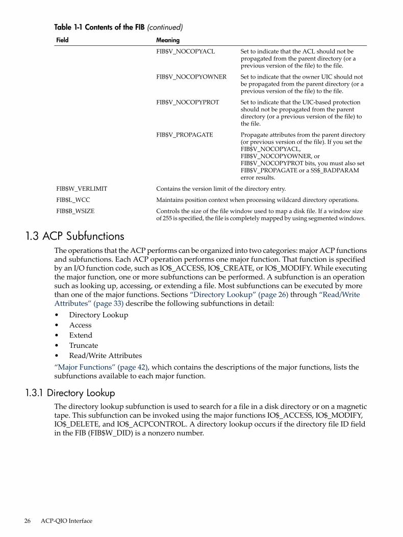
Table 1-1 Contents of the FIB (continued)
MeaningField
Set to indicate that the ACL should not bepropagated from the parent directory (or aprevious version of the file) to the file.
FIB$V_NOCOPYACL
Set to indicate that the owner UIC should notbe propagated from the parent directory (or aprevious version of the file) to the file.
FIB$V_NOCOPYOWNER
Set to indicate that the UIC-based protectionshould not be propagated from the parentdirectory (or a previous version of the file) tothe file.
FIB$V_NOCOPYPROT
Propagate attributes from the parent directory(or previous version of the file). If you set theFIB$V_NOCOPYACL,FIB$V_NOCOPYOWNER, orFIB$V_NOCOPYPROT bits, you must also setFIB$V_PROPAGATE or a SS$_BADPARAMerror results.
FIB$V_PROPAGATE
Contains the version limit of the directory entry.FIB$W_VERLIMIT
Maintains position context when processing wildcard directory operations.FIB$L_WCC
Controls the size of the file window used to map a disk file. If a window sizeof 255 is specified, the file is completely mapped by using segmented windows.
FIB$B_WSIZE
1.3 ACP SubfunctionsThe operations that the ACP performs can be organized into two categories: major ACP functionsand subfunctions. Each ACP operation performs one major function. That function is specifiedby an I/O function code, such as IO$_ACCESS, IO$_CREATE, or IO$_MODIFY. While executingthe major function, one or more subfunctions can be performed. A subfunction is an operationsuch as looking up, accessing, or extending a file. Most subfunctions can be executed by morethan one of the major functions. Sections “Directory Lookup” (page 26) through “Read/WriteAttributes” (page 33) describe the following subfunctions in detail:• Directory Lookup• Access• Extend• Truncate• Read/Write Attributes“Major Functions” (page 42), which contains the descriptions of the major functions, lists thesubfunctions available to each major function.
1.3.1 Directory LookupThe directory lookup subfunction is used to search for a file in a disk directory or on a magnetictape. This subfunction can be invoked using the major functions IO$_ACCESS, IO$_MODIFY,IO$_DELETE, and IO$_ACPCONTROL. A directory lookup occurs if the directory file ID fieldin the FIB (FIB$W_DID) is a nonzero number.
26 ACP-QIO Interface

1.3.1.1 Input ParametersTable 1-2 lists the FIB fields that control the processing of a lookup subfunction.
Table 1-2 FIB Fields (Lookup Control)
MeaningSubfieldsField
Name string control. The following namecontrol bits are applicable to a lookupoperation:
FIB$W_NMCTL
Set to match all name field values.FIB$V_ALLNAM
Set to match all field type values.FIB$V_ALLTYP
Set to match all version field values.FIB$V_ALLVER
When set, performs case-sensitive lookup;when clear, performs case-blind lookup.
FIB$V_CASE_SENSITIVE
Set to search a directory for the file ID inFIB$W_FID.
FIB$V_FINDFID
Caller can accept (8-bit) ODS-2 or ISO Latin-1formats.
FIB$V_NAMES_8BIT
Caller can accept (16-bit) Unicode (UCS-2)formats.
FIB$V_NAMES_16BIT
Set if name string contains wildcards. Settingthis bit causes wildcard context to be returnedin FIB$L_WCC.
FIB$V_WILD
File identification. The file ID of the file foundis returned in this field.
FIB$W_FID
Contains the file identifier of the directory file.This field must be a nonzero number.
FIB$W_DID
Maintains position context when processingwildcard directory operations.
FIB$L_WCC
The following access control flag is applicableto a lookup subfunction:
FIB$L_ACCTL
Set to rewind magnetic tape before lookup. Ifnot set, a magnetic tape is searched from itscurrent position.
FIB$V_REWIND
Contains the format of the input filespecification. The following formats are valid:
FIB$B_NAME_FORMAT_IN
ODS-2 Format (default)FIB$C_ODS2
ISO Latin-1 FormatFIB$C_ISO_LATIN
Unicode (UCS-2) FormatFIB$C_UCS2
Contains the format of the output filespecification. The following formats are valid:
FIB$B_NAME_FORMAT_OUT
ODS-2 Format (default)FIB$C_ODS2
ISO Latin-1 FormatFIB$C_ISO_LATIN
Unicode (UCS-2) FormatFIB$C_UCS2
QIO arguments P2 through P5 (see Figure 1-1) are passed as values. The second argument, P2,specifies the address of the descriptor for the file name string to be searched for in the directory.The file name string must have one of the following two formats:
1.3 ACP Subfunctions 27
name.type;version name.type.version
The name and type can be any combination of alphanumeric characters, and the dollar sign ($),asterisk (*), and percent (%) characters. The version must consist of numeric characters optionallypreceded by a minus sign (-) (only for disk devices) or a single asterisk. The total number ofalphanumeric and percent characters in the name field and in the type field must not exceed 39.Any number of additional asterisks can be present.If any of the bits FIB$V_ALLNAM, FIB$V_ALLTYP, and FIB$V_ALLVER are set, then the contentsof the corresponding field in the name string are ignored and the contents are assumed to be anasterisk.Note that the file name string cannot contain a directory string. The directory is specified by theFIB$W_DID field (see Table 1-2). Only RMS can process directory strings.Argument P3 is the address of a word to receive the resultant file name string length. ArgumentP4 is the address of a descriptor for a buffer to receive the resultant file name string. The resultantstring is not padded. The P3 and P4 arguments are optional.
1.3.1.2 OperationThe system searches either the directory file specified by FIB$W_DID or the magnetic tape forthe file name specified in the P2 file name parameter. The actual file name found and its lengthare returned in the P3 and P4 length and result string buffers. The file ID of the file found isreturned in FIB$W_FID and can be used in subsequent operations as the major function isprocessed.Zero and negative version numbers have special significance in a disk lookup operation. Specifying0 as a version number causes the latest version of the file to be found. Specifying -1 locates thesecond most recent version, -2 the third most recent, and so forth. Specifying a version of -0locates the lowest numbered version of the file. For magnetic tape lookups, a version number of0 locates the first occurrence of the file encountered; negative version numbers are not allowed.Wildcard lookups are performed by specifying the appropriate wildcard characters in the namestring and setting FIB$V_WILD. (The name control bits FIB$V_ALLNAM, FIB$V_ALLTYP, andFIB$V_ALLVER can also be used in searching for wildcard entries, but they are intended primarilyfor compatibility mode use.) On the first lookup, FIB$L_WCC should contain zero entries. Oneach lookup, the ACP returns a nonzero value in FIB$L_WCC, which must be passed back onthe next lookup call. In addition, you must pass the resultant name string returned by the previouslookup using the P4 result string buffer, and its length in the P3 result length word. This stringis used together with FIB$L_WCC to continue the wildcard search at the correct position in thedirectory.To perform a lookup by file ID, set the name control bit FIB$V_FINDFID. When this bit is set,the system searches SYS$EI1000.EXE the directory for an entry containing the file ID specifiedin FIB$W_FID, and the name of the entry found is returned in the P3 and P4 result parameters.Note that if a directory contains multiple entries with the same file ID, only the first entry canbe located with this technique.Lookups by file ID should be done only when the file name is not available, because lookups bythis method are often significantly slower than lookups by file name.Because not all programs can handle all of the available name formats, the FIB$W_NMCTL flagsgovern the name formats, and are returned as follows:• FIB$V_ NAMES_8BIT clear
FIB$V_ NAMES_16BIT clearOnly ODS-2 format names are returned. Note that this includes specifications that wereoriginally in ISO Latin-1 format or Unicode (UCS-2) format but converted to ODS-2 format
28 ACP-QIO Interface

before being stored on the volume. All specifications are converted to uppercase beforebeing returned.
• FIB$V_ NAMES_8BIT setFIB$V_ NAMES_16BIT clearOnly those file specifications stored in ODS-2 and ISO Latin-1 formats are returned. Thevalue in the FIB$B_NAME_FORMAT_OUT field indicates the format of the particular namebeing returned. ODS-2 format file specifications are not converted to uppercase before beingreturned.
• FIB$V_ NAMES_8BIT clearFIB$V_ NAMES_16BIT setAll file specifications are returned in Unicode (UCS-2) format.
• FIB$V_ NAMES_8BIT setFIB$V_ NAMES_16BIT setFile specifications are returned in the format stored on the volume. This is the simplestformat compatible with the file name syntax and the characters it contains. For example, aspecification originally in Unicode format that only contains characters that are part of theISO Latin-1 character set are returned in ISO Latin-1 format.
1.3.1.3 Directory Entry ProtectionA directory entry is protected with the same protection code as the file itself. For example, if adirectory file is protected against delete access, then the file name has the same protection.Consequently, a nonprivileged user (that is, a user who is not the volume owner, or a user whodoes not have SYSPRV) cannot rename a file because renaming a file is essentially the same asdeleting the file name. This protection is applied regardless of the protection on the directoryfile.Nonprivileged users can neither write directly into a .DIR;1 directory file nor turn off the directorybit in a directory file header.
1.3.2 AccessThe access subfunction is used to open a file so that virtual read or write operations can beperformed. This subfunction can be invoked using the major functions IO$_CREATE andIO$_ACCESS (see “Create File” (page 42) and “Access File” (page 44)). An access subfunctionis performed if the IO$M_ACCESS modifier is specified in the I/O function code.
1.3.2.1 Input ParametersTable 1-3 lists the FIB fields that control the processing of an access subfunction.
Table 1-3 FIB Fields (Access Control)
MeaningSubfieldsField
Specifies field values that control access to the file. The followingaccess control bits are applicable to the access subfunction:
FIB$L_ACCTL
Set for write access; clear for read-only access.FIB$V_WRITE
Set to deny read access to others. (You must have write privilegeto the file to use this option.)
FIB$V_NOREAD
Set to deny write access to others.FIB$V_NOWRITE
Set to prevent the file from being truncated; clear to allowtruncation.
FIB$V_NOTRUNC
1.3 ACP Subfunctions 29
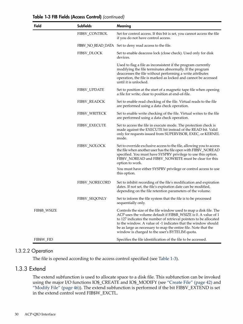
Table 1-3 FIB Fields (Access Control) (continued)
MeaningSubfieldsField
Set for control access. If this bit is set, you cannot access the fileif you do not have control access.
FIB$V_CONTROL
Set to deny read access to the file.FIB$V_NO_READ_DATA
Set to enable deaccess lock (close check). Used only for diskdevices.
FIB$V_DLOCK
Used to flag a file as inconsistent if the program currentlymodifying the file terminates abnormally. If the programdeaccesses the file without performing a write attributesoperation, the file is marked as locked and cannot be accesseduntil it is unlocked.
Set to position at the start of a magnetic tape file when openinga file for write; clear to position at end-of-file.
FIB$V_UPDATE
Set to enable read checking of the file. Virtual reads to the fileare performed using a data check operation.
FIB$V_READCK
Set to enable write checking of the file. Virtual writes to the fileare performed using a data check operation.
FIB$V_WRITECK
Set to access the file in execute mode. The protection check ismade against the EXECUTE bit instead of the READ bit. Validonly for requests issued from SUPERVISOR, EXEC, or KERNELmode.
FIB$V_EXECUTE
Set to override exclusive access to the file, allowing you to accessthe file when another user has the file open with FIB$V_NOREADspecified. You must have SYSPRV privilege to use this option.FIB$V_NOREAD and FIB$V_NOWRITE must be clear for thisoption to work.You must have either SYSPRV privilege or control access to usethis option.
FIB$V_NOLOCK
Set to inhibit recording of the file's modification and expirationdates. If not set, the file's expiration date can be modified,depending on the file retention parameters of the volume.
FIB$V_NORECORD
Set to inform the file system that the file is to be processedsequentially only.
FIB$V_SEQONLY
Controls the size of the file window used to map a disk file. TheACP uses the volume default if FIB$B_WSIZE is 0. A value of 1to 127 indicates the number of retrieval pointers to be allocatedto the window. A value of -1 indicates that the window shouldbe as large as necessary to map the entire file. Note that thewindow is charged to the user's BYTELIM quota.
FIB$B_WSIZE
Specifies the file identification of the file to be accessed.FIB$W_FID
1.3.2.2 OperationThe file is opened according to the access control specified (see Table 1-3).
1.3.3 ExtendThe extend subfunction is used to allocate space to a disk file. This subfunction can be invokedusing the major I/O functions IO$_CREATE and IO$_MODIFY (see “Create File” (page 42) and“Modify File” (page 46)). The extend subfunction is performed if the bit FIB$V_EXTEND is setin the extend control word FIB$W_EXCTL.
30 ACP-QIO Interface

1.3.3.1 Input ParametersTable 1-4 lists the FIB fields that control the processing of an extend subfunction.
Table 1-4 FIB Fields (Extend Control)
MeaningSubfieldsField
Extend control flags. The following flags are applicableto the extend subfunction:
FIB$W_EXCTL
Set to enable extension.FIB$V_EXTEND
Set to inhibit generation of extension file headers.FIB$V_NOHDREXT
Allocates contiguous space. The extend operation failsif the necessary contiguous space is not available.
FIB$V_ALCON
Allocates the maximum amount of contiguous space.FIB$V_ALCONB
If both FIB$V_ALCON and FIB$V_ALCONB are set, asingle contiguous area, whose size is the largestavailable but not greater than the size requested, isallocated.
Marks the file as contiguous. This bit can only be set ifthe file does not have space already allocated to it.
FIB$V_FILCON
Allocates the extend size (FIB$L_EXSZ) or the systemdefault, whichever is greater.
FIB$V_ALDEF
Specifies the number of blocks to allocate to the file.FIB$L_EXSZ
The number of blocks actually allocated for thisoperation is returned in this longword. More blocksthan requested can be allocated to meet clusterboundaries.
Returns the starting virtual block number of the blocksallocated. FIB$L_EXVBN must initially contain 0 blocks.
FIB$L_EXVBN
Contains option bits that control the placement ofallocated blocks. The following bits are defined:
FIB$B_ALOPTS
Set to require exact placement; clear to specifyapproximate placement. If this bit is set and thespecified blocks are not available, the extend operationfails.
FIB$V_EXACT
Set to locate allocated space within a cylinder. Thisoption functions correctly only when FIB$V_ALCONor FIB$V_ALCONB is specified.
FIB$V_ONCYL
Contains the interpretation mode of the allocation(FIB$W_ALLOC) field. One of the following values canbe specified:
FIB$B_ALALIGN
No placement data. The remainder of the allocationfield is ignored.
(zero)
Location is specified as a byte relative volume number(RVN) in FIB$B_LOC_RVN and a cylinder number inFIB$L_LOC_ADDR.
FIB$C_CYL
Location is specified as a byte RVN inFIB$B_LOC_RVN, followed by a longword logical blocknumber (LBN) in FIB$L_LOC_ADDR.
FIB$C_LBN
Location is specified as a longword virtual blocknumber (VBN) of the file being extended inFIB$L_LOC_ADDR. A 0 VBN or one that fails to mapindicates the end of the file.
FIB$C_VBN
1.3 ACP Subfunctions 31

Table 1-4 FIB Fields (Extend Control) (continued)
MeaningSubfieldsField
Location is specified as a three-word file ID inFIB$W_LOC_FID, followed by a longword VBN of thatfile in FIB$L_LOC_ADDR. A 0 file ID indicates the filebeing extended. A 0 VBN or one that fails to mapindicates the end of that file.
FIB$C_RFI
Contains the desired physical location of the blocksbeing allocated. Interpretation of the field is controlledby the FIB$B_ALALIGN field. The following subfieldsare defined:
FIB$W_ALLOC
Three-word related file ID for RFI placement.FIB$W_LOC_FID
Related file number.FIB$W_LOC_NUM
Related file sequence number.FIB$W_LOC_SEQ
Related file RVN or placement RVN.FIB$B_LOC_RVN
Related file number extension.FIB$B_LOC_NMX
Placement LBN, cylinder, or VBN.FIB$L_LOC_ADDR
1.3.3.2 OperationThe specified number of blocks are allocated and appended to the file. The virtual block numberassigned to the first block allocated is returned in FIB$L_EXVBN. The actual number of blocksallocated is returned in FIB$L_EXSZ.The actual number of blocks allocated is also returned in the second longword of the user's I/Ostatus block. If a contiguous allocation (FIB$V_ALCON) fails, the size of the largest contiguousspace available on the disk is returned in the second longword of the user's I/O status block.
1.3.4 TruncateThe truncate subfunction is used to remove space from a disk file. This subfunction can be invokedby the major I/O functions IO$_DEACCESS and IO$_MODIFY (see “Deaccess File” (page 45)and “Modify File” (page 46)). The truncate subfunction is performed if the bit FIB$V_TRUNCis set in the extend control word FIB$W_EXCTL.
1.3.4.1 Input ParametersTable 1-5 lists the FIB fields that control the processing of a truncate subfunction.
Table 1-5 FIB Fields (Truncate Control)
MeaningSubfieldsField
Extend control flags. The following flags are applicableto the truncate subfunction:
FIB$W_EXCTL
Must be set to enable truncation.FIB$V_TRUNC
Set to append the truncated blocks to the bad block file,instead of returning them to the free storage pool. Onlyone cluster can be deallocated. This is most easilyaccomplished by specifying the last VBN of the file inFIB$L_EXVBN. SYSPRV privilege or ownership of thevolume is required to deallocate blocks to the bad blockfile.
FIB$V_MARKBAD
32 ACP-QIO Interface
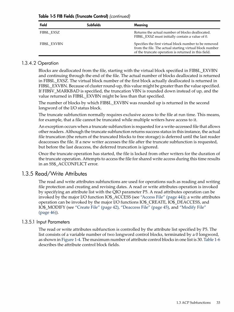
Table 1-5 FIB Fields (Truncate Control) (continued)
MeaningSubfieldsField
Returns the actual number of blocks deallocated.FIB$L_EXSZ must initially contain a value of 0.
FIB$L_EXSZ
Specifies the first virtual block number to be removedfrom the file. The actual starting virtual block numberof the truncate operation is returned in this field.
FIB$L_EXVBN
1.3.4.2 OperationBlocks are deallocated from the file, starting with the virtual block specified in FIB$L_EXVBNand continuing through the end of the file. The actual number of blocks deallocated is returnedin FIB$L_EXSZ. The virtual block number of the first block actually deallocated is returned inFIB$L_EXVBN. Because of cluster round-up, this value might be greater than the value specified.If FIB$V_MARKBAD is specified, the truncation VBN is rounded down instead of up, and thevalue returned in FIB$L_EXVBN might be less than that specified.The number of blocks by which FIB$L_EXVBN was rounded up is returned in the secondlongword of the I/O status block.The truncate subfunction normally requires exclusive access to the file at run time. This means,for example, that a file cannot be truncated while multiple writers have access to it.An exception occurs when a truncate subfunction is requested for a write-accessed file that allowsother readers. Although the truncate subfunction returns success status in this instance, the actualfile truncation (the return of the truncated blocks to free storage) is deferred until the last readerdeaccesses the file. If a new writer accesses the file after the truncate subfunction is requested,but before the last deaccess, the deferred truncation is ignored.Once the truncate operation has started, the file is locked from other writers for the duration ofthe truncate operation. Attempts to access the file for shared write access during this time resultsin an SS$_ACCONFLICT error.
1.3.5 Read/Write AttributesThe read and write attributes subfunctions are used for operations such as reading and writingfile protection and creating and revising dates. A read or write attributes operation is invokedby specifying an attribute list with the QIO parameter P5. A read attributes operation can beinvoked by the major I/O function IO$_ACCESS (see “Access File” (page 44)); a write attributesoperation can be invoked by the major I/O functions IO$_CREATE, IO$_DEACCESS, andIO$_MODIFY (see “Create File” (page 42), “Deaccess File” (page 45), and “Modify File”(page 46)).
1.3.5.1 Input ParametersThe read or write attributes subfunction is controlled by the attribute list specified by P5. Thelist consists of a variable number of two longword control blocks, terminated by a 0 longword,as shown in Figure 1-4. The maximum number of attribute control blocks in one list is 30. Table 1-6describes the attribute control block fields.
1.3 ACP Subfunctions 33

Figure 1-4 Attribute Control Block Format
ATR$W_TYPE
ATR$L_ADDR
ATR$W_SIZE
(Additional Control Blocks)
31 16 15 0
0
Table 1-6 Attribute Control Block Fields
MeaningField
Specifies the number of bytes of the attribute to be written, or the size of the buffer into whichthe attribute is to be read. Legal values for writing attributes are from 0 to the maximum sizeof the particular attribute (see Table 1-7 (page 34)), and legal values for the reading attributesare from 0 to the maximum unsigned 16-bit integer.
ATR$W_SIZE
Identifies the individual attribute to be read or written.ATR$W_TYPE
Contains the buffer address of the memory space to or from which the attribute is to betransferred. The attribute buffer must be writable.
ATR$L_ADDR
Table 1-7 lists the valid attributes for ACP-QIO functions. The maximum size (in bytes) isdetermined by the required attribute configuration. For example, the Radix-50 file name(ATR$S_FILNAM) uses only 6 bytes, but it is always accompanied by the file type and file version,so a total of 10 bytes is required. Each attribute has two names: one for the code (for example,ATR$C_UCHAR) and one for the size (for example, ATR$S_UCHAR).
Table 1-7 ACP-QIO Attributes
MeaningMaximum Size(bytes)
Attribute Name1
Corresponds to POSIX st_atime and reflects the last time afile was accessed.
8ATR$C_ACCDATE2
Access mode for following attribute descriptors.1ATR$C_ACCESS_MODE
File access level.1ATR$C_ACLEVEL3 4 5 6
Returns the size, in bytes, of the object's ACL.4ATR$C_ACLLENGTH6 7
Adds an ACE to the beginning of the ACL when the ACEcontext value is 0; to the end of the ACL when the ACE contextvalue is -1; or at a location pointed to by a priorACL$C_FNDACETYP or ACL$C_FNDACLENT.
255ATR$C_ADDACLENT8 6 7
Compatibility mode allocation data.14ATR$C_ALCONTROL
Revision count (2 binary bytes), revision date, creation date,and expiration date, in ASCII. Format: DDMMMYY (revisiondate), HHMMSS (time), DDMMMYY (creation date), HHMMSS(time), DDMMMYY (expiration date). (The format containsno embedded spaces or commas.)
35ATR$C_ASCDATES3 9
34 ACP-QIO Interface

Table 1-7 ACP-QIO Attributes (continued)
MeaningMaximum Size(bytes)
Attribute Name1
File name, type, and version, in ASCII, including punctuation.Format: name.type;version.Magnetic tape: contains 17-character file identifier (ANSI a);no version number. Overrides all other file name and file typespecifications if supplied on input operations. If specified onan access operation and you want only a value to be returned,specify (in ATR$W_SIZE) a buffer of greater than 17 bytes.See “Attribute Descriptions” (page 37) for additionalinformation.
252 (ODS-5) 86(ODS-2)
ATR$C_ASCNAME
Corresponds to POSIX st_ctime and reflects the last time afile attribute was modified.
8ATR$C_ATTDATE2
File back link pointer.6ATR$C_BACKLINK6
64-bit backup date and time.8ATR$C_BAKDATE4 5 10 6
Magnetic tape block size.2ATR$C_BLOCKSIZE
Offset length for ANSI magnetic tape header label buffer.2ATR$C_BUFFER_OFFSET9
64-bit creation date and time.8ATR$C_CREDATE
Deletes an access control entry pointed to by the buffer addressor, if the buffer address is 0, the ACE pointed to by a priorACL$C_FNDACETYP or ACL$C_FNDACLENT.
255ATR$C_DELACLENT8 6 7
Delete the entire ACL, including protected entries.255ATR$C_DELETE_ALL8 6 7
Deletes the entire ACL with the exception of protected ACEs.255ATR$C_DELETEACL8 6 7
Directory update sequence count.2ATR$C_DIRSEQ6
End of magnetic tape label processing; provides AST controlblock.
4ATR$C_ENDLBLAST
Expiration date in ASCII. Format: DDMMMYY.7ATR$C_EXPDAT3
64-bit expiration date and time.8ATR$C_EXPDATE3
Convert FID to file specification. See “Attribute Descriptions”(page 37) for additional information.
4098 (ODS-5)512 (ODS-2)
ATR$C_FILE_SPEC6
6-byte Radix-50 file name plus ATR$C_FILTYP andATR$C_FILVER. See “Attribute Descriptions” (page 37) foradditional information.
10ATR$C_FILNAM
2-byte Radix-50 file type plus ATR$C_FILVER. See “AttributeDescriptions” (page 37) for additional information.
4ATR$C_FILTYP
2-byte binary version number. See “Attribute Descriptions”(page 37) for additional information.
2ATR$C_FILVER
Locates an ACE pointed to by its buffer address.255ATR$C_FNDACLENT6 7
Locates an ACE of the type pointed to by its buffer address.255ATR$C_FNDACETYP6 7
File protection.2ATR$C_FPRO3 4
Return an ACE that grants or denies access to the object.255ATR$C_GRANT_ACE6 7
ANSI magnetic tape header label accessibility character.1ATR$C_HDR1_ACC
Complete file header. This attribute is read only.512ATR$C_HEADER
High-water mark (user read-only).4ATR$C_HIGHWATER6
1.3 ACP Subfunctions 35

Table 1-7 ACP-QIO Attributes (continued)
MeaningMaximum Size(bytes)
Attribute Name1
Journal control flags.1ATR$C_JOURNAL6
Count of hardlinks.2ATR$C_LINKCOUNT
ACE used to gain access (if any). This attribute can only beretrieved on the initial file access or create operation.
255ATR$C_MATCHING_ACE10 6
Replaces the ACE pointed to by a prior ACL$C_FNDACETYPor ACL$C_FNDACLENT with the ACE pointed to by its bufferaddress.
255ATR$C_MODACLENT8 6 7
Corresponds to POSIX st_mtime and reflects the last timedata was modified.
8ATR$C_MODDATE2
Advance to the next ACE in the ACL.4ATR$C_NEXT_ACE6 7
Privileges used to gain access. This attribute can only beretrieved on the initial file access or create operation.
4ATR$C_PRIVS_USED6
Reads the ACE pointed to by ACL$C_FNDACETYP orACL$C_FNDACLENT into the buffer.
255ATR$C_READACE6 7
Reads the entire ACL or as much as will fit in the suppliedbuffer. Only complete ACEs are transferred.
512ATR$C_READACL6 7
Record attribute area. “ACP-QIO Record Attributes Area”(page 39) describes the record attribute area in detail.
32ATR$C_RECATTR4
Modifies the reserve area.380ATR$C_RESERVED11
64-bit revision date and time.8ATR$C_REVDATE3 4
2-byte record protection.2ATR$C_RPRO6
File security mask and limit.8ATR$C_SEMASK6
Statistics block. This attribute is read only. “ACP-QIOAttributes Statistics Block” (page 41) describes the statisticsblock in detail.
32ATR$C_STATBLK
4-byte file characteristics. (The file characteristics bits are listedfollowing this table.)
4ATR$C_UCHAR3 9
User file label. This attribute is not supported for disk devices.80ATR$C_USERLABEL
4-byte file owner UIC.4ATR$C_UIC3
4-byte file owner UIC. This attribute is read only.4ATR$C_UIC_RO
1 Attributes with an ATR$C_ prefix have two names: one with the ATR$C prefix for the code and one with an ATR$S_prefix for the size, which is not included in the list.
2 Not supported by all ACPs. Maintained on ODS-5 volumes when access dates are enabled using the DCL INITIALIZEor SET VOLUME commands. Not maintained on ODS-2 volumes.
3 Protected (can be written to only by system or owner).4 Locked (cannot be written to while the file is locked).5 For Files-11 C/D; returns 0.6 Not supported for Files-11 On Disk Structure Level 1 or magnetic tapes.7 The status from this attribute operation is returned in FIB$L_ACL_STATUS.8 Exclusive access required. This operation does not complete successfully if other readers or writers are allowed.9 Not supported on writer operations to MTAACP; defaults are returned on read operations.10 Can be written only by the system, owner, or someone holding READALL privilege.11 The actual length available can decrease if the file is extended in a noncontiguous manner or if an ACL is applied
to the file.
36 ACP-QIO Interface

Table 1-8 lists the bits contained in the file characteristics longword, which is read with theATR$C_UCHAR attribute.
Table 1-8 File Characteristics Bits
MeaningBits
Do not back up file.FCH$M_NOBACKUP
Verify all read operations.FCH$M_READCHECK
Verify all write operations.FCH$M_WRITCHECK
Keep file as contiguous as possible.FCH$M_CONTIGB
File is deaccess-locked.FCH$M_LOCKED
File is contiguous.FCH$M_CONTIG
File's ACL is corrupt.FCH$M_BADACL
File is an intermediate spool file.FCH$M_SPOOL
File is a directory.FCH$M_DIRECTORY
File contains bad blocks.FCH$M_BADBLOCK
File is marked for deletion.FCH$M_MARKDEL
Erase file contents before deletion.FCH$M_ERASE
File has an associated file.FCH$M_ASSOCIATED1
Suppress existence of file.FCH$M_EXISTENCE1
Disable movefile operations on this file.FCH$M_NOMOVE
File is not shelvable.FCH$M_NOSHELVABLE
File is shelved.FCH$M_SHELVED
1 Files-11 C/D only.
1.3.5.2 Attribute DescriptionsThis section contains descriptions of the following attribute codes that are listed in Table 1-7:• ATR$C_ASCNAME• ATR$C_FILE_SPEC• ATR$C_FILNAM• ATR$C_FILTYP• ATR$C_FILVERATR$C_ASCNAMEThe ATR$C_ASCNAME attribute allows the file specification stored in a file's primary file headerto be read and written.Reading the ATR$C_ASCNAME AttributeFor ODS-5 volumes, the file specification is returned in the supplied buffer, and the name formatis returned in the FIB$B_ASCNAME_FORMAT cell.The format in which the name is returned is controlled by the settings of the FIB$V_NAMES_8BITand FIB$V_NAMES_16BIT flags in the same way as the output file specification parameter. Apseudoname can be returned in place of the actual file specification if the format is not one ofthose the calling program can accept.Unlike the output file specification parameter, the length of a file specification contained in theASCNAME attribute is not passed back explicitly. To determine the length of the file specification,the calling program must search the attribute buffer for the first occurrence of the padding
1.3 ACP Subfunctions 37

character. If neither the FIB$V_NAMES_8BIT nor the FIB$V_NAMES_16BIT flag is set, the bufferis padded with space (note that only ODS-2 format names are returned in this case). If one ormore of the flags are set, the attribute buffer is padded with zeros.
NOTE: The file system does not enforce a minimum length on the attribute buffer. If the filespecification is longer than the attribute buffer, the value returned is truncated without signalingan error or warning.In contrast, the file system does enforce a maximum size for the attribute buffer. Supplying alarger buffer returns a BADPARAM error.
Writing the ATR$C_ASCNAME Attribute
The ASCNAME attribute can only be written for files on ODS-2 or ODS-5 volumes providedthat the FIB$V_NAMES_8BIT and FIB$V_NAMES_16BIT flags are clear.The ability to write this attribute is only intended to provide compatibility with existingapplications that do so. New and modified programs should not write this attribute. Changingits value can prevent a file from being permanently deleted.In those cases where it is legal to write the attribute, the contents of the attribute buffer (up to252 bytes) are copied to the file name field in the file header. For ODS-5 headers, the format isset to ODS-2, and the file name length is set to the offset of the first space character. This can be252 bytes or the length of the supplied buffer, whichever is the least.ATR$C_FILE_SPECThe FILE_SPEC attribute is a read-only attribute that returns the physical file specification in theform:DDnn:[DIR1.DIR2_DIRn]name.type;1
The file name returned is that from the file header, which may be different from that in thedirectory. The specification may be incomplete if any errors are encountered while reading thefile headers of any of the directories in the path.For files on ODS-5 volumes, the path may contain file names that are in any of the three nameformats. This creates a number of problems; for instance, the presence of periods in a directoryname could return an ambiguous path specification. To avoid this and other problems, the filesystem makes use of services provided by RMS to translate the file specification and thecomponents of the path to their escaped form.If the escaped form of the path is longer than can be accommodated by the buffer for the attribute,one or more directories in the path may be replaced by the DID of the rightmost of those replaced.This process is identical to that performed by RMS.However, if the file specification, even after DID abbreviation, is longer than can be accommodatedby the buffer, the file name is truncated. The file specification string returned to the user bufferhas a 2-byte count prefix. The count contains the number of bytes for the untruncated filespecification. If the count is greater than the size of the user buffer (minus the two bytes thatcontain the count), the user can conclude that the returned file specification has been truncated.ATR$C_FILNAM, ATR$C_FILTYP, and ATR$C_FILVERThe first two of these attributes allow the file name and file type to be read and written usingRadix-50 encoding. This encoding scheme enables 3 characters to be packed into a 16-bit word.Only 38 characters in the ODS-2 format set are valid for Radix-50 names, with the exceptionsbeing dash (-) and underscore (_).The maximum component lengths of a Radix-50 encoded file specification are:• File name: 15 characters (10 bytes)• File type: 6 characters (4 bytes)
38 ACP-QIO Interface

As a result of the additional character and length restrictions, only a subset of legal ODS-2 filenames is can be expressed in the Radix-50 encoding.The file system only attempts to read or write the three attributes if the format of the existingfile name in the file header is ODS-2. If this is not the case, a NORAD50 error will be returned.If the existing file name is in ODS-2 format, but is incompatible with the Radix-50 encoding orthe length limits on Radix-50 file names, a BADFILENAME error will be returned.The ATR$C_FILVER attribute allows the file version number in the file header to be read orwritten as a 2-byte integer. As the process requires the existing file name to be converted into aRadix-50 file name, the previous restriction also applies to this attribute.
1.4 ACP-QIO Record Attributes AreaFigure 1-5 shows the format of the record attributes area.
Figure 1-5 ACP-QIO Record Attributes Area
FAT$W_RSIZE
FAT$W_DEFEXT
FAT$W_VERSIONS
FAT$W_MAXREC
FAT$B_RATTRIB FAT$B_TYPE*
FAT$W_GBC(alias FAT$w_GBC16)FAT$B_RECATTR_FLAGS
FAT$L_GBC32
Reserved
Not Used
FAT$L_HIBLK
FAT$L_EFBLK
31
4
8
12
16
20
24
28
24 23 1516 78 0
FAT$B_VFCSIZE FAT$B_BKTSIZE FAT$W_FFBYTE
*FAT$V_RTYPE Bits 1 - 3; FAT$V_FILEORG Bits 4 - 7
Table 1-9 lists the record attributes values and their meanings.
Table 1-9 ACP Record Attributes Values
MeaningField Value
Record type. Contains FAT$V_RTYPE and FAT$V_FILEORG.FAT$B_TYPE
Record type. The following bit values are defined:FAT$V_RTYPE
Fixed-length recordFAT$C_FIXED
Variable-length recordFAT$C_VARIABLE
Variable-length record with fixed controlFAT$C_VFC
Undefined record format (stream binary)FAT$C_UNDEFINED
RMS stream formatFAT$C_STREAM
Stream terminated by LFFAT$C_STREAMLF
Stream terminated by CRFAT$C_STREAMCR
File organization. The following bit values are defined:FAT$V_FILEORG
Direct file organization1FAT$C_DIRECT
Indexed file organizationFAT$C_INDEXED
Relative file organizationFAT$C_RELATIVE
Sequential file organizationFAT$C_SEQUENTIAL
1.4 ACP-QIO Record Attributes Area 39

Table 1-9 ACP Record Attributes Values (continued)
MeaningField Value
Record attributes. The following bit values are defined:FAT$B_RATTRIB
Fortran carriage controlFAT$M_FORTRANCC
Implied carriage controlFAT$M_IMPLIEDCC
Print file carriage controlFAT$M_PRINTCC
No spanned recordsFAT$M_NOSPAN
Record count word (RCW) is MSB formattedFAT$M_MSBRCW2
Record size in bytes.FAT$W_RSIZE
Highest allocated VBN. The ACP maintains this field when the file is extended ortruncated. Attempts to modify this field in a write attributes operation are ignored.
FAT$L_HIBLK3
High-order 16 bitsFAT$W_HIBLKH
Low-order 16 bitsFAT$W_HIBLKL
End of file VBNFAT$L_EFBLK3 4
High-order 16 bitsFAT$W_EFBLKH
Low-order 16 bitsFAT$W_EFBLKL
First free byte in FAT$L_EFBLK.FAT$W_FFBYTE
Bucket size, in blocks.FAT$B_BKTSIZE
Size in bytes of fixed-length control for VFC records.FAT$B_VFCSIZE
Maximum record size, in bytes.FAT$W_MAXREC
Default extend quantity.FAT$W_DEFEXT
Global buffer count.FAT$W_GBC
Default version limit; valid only if the file is a directoryFAT$W_VERSIONS
Enhanced longword global buffer count.FAT$L_GBC32
Record attributes flags. The following bit values are defined:FAT$B_RECATTR_FLAGS
Interpret value in FAT$L_GBC32 as a percentinstead of count.
FAT$M_GBC_PERCENT
RMS should set default for global buffer count andignore any values in FAT$W_GBC orFAT$L_GBC32.
FAT$M_GBC_DEFAULT
1 Defined but not implemented.2 Variable-length record format (FAT$C_VARIABLE) only.3 Inverted format field. The high- and low-order 16 bits are transposed for compatibility with PDP-11 software.4 When the end-of-file position corresponds to a block boundary; by convention, FAT$L_EFBLK contains the end-of-file
VBN plus 1 and FAT$W_FFBYTE contains 0.
40 ACP-QIO Interface

1.5 ACP-QIO Attributes Statistics BlockFigure 1-6 shows the format of the attributes statistics block. Table 1-10 lists the contents of thisblock.
Figure 1-6 ACP-QIO Attributes Statistics Block
SBK$L_STLBN
SBK$L_READS
SBK$L_WRITES
SBK$W_LCNT
SBK$W_TCNT
SBK$L_FILESIZE
SBK$L_FCB SBK$B_LCNT SBK$B_ACNT
SBK$W_ACNT
SBK$W_WCNT
31 1516 78 0
(Not Used) FAT$W_FFBYTE
Table 1-10 Contents of the Statistics Block
MeaningSubfieldsField
Contains the starting LBN of the file if the file is contiguous.If the file is not contiguous, this field contains a value of 0.The LBN appears as an inverted longword (the high- andlow-order 16 bits are transposed for PDP-11 compatibility).The following subfields are defined:
SBK$L_STLBN
Starting LBN (high-order 16 bits)SBK$W_STLBNH
Starting LBN (low-order 16 bits)SBK$W_STLBNL
Contains the size of the file in blocks. The file size appearsas an inverted longword (the high- and low-order 16 bitsare transposed for PDP-11 compatibility). The followingsubfields are defined:
SBK$L_FILESIZE
File size (high-order 16 bits)SBK$W_FILESIZH
File size (low-order 16 bits)SBK$W_FILESIZL
Access count (low byte). Field is for PDP-11 compatibility.SBK$B_ACNT1
Lock count (low byte). Field is for PDP-11 compatibility.SBK$B_LCNT1
System pool address of the file's file control block.SBK$L_FCB
Access count (number of channels with file open currently).SBK$W_ACNT1
Lock count (the number of access operations that havelocked the file against writers).
SBK$W_LCNT1
Writer count (the number of channels that currently havethe file open for write).
SBK$W_WCN1
Truncate lock count (the number of access operations thathave locked the file against truncation).
SBK$W_TCNT1
Number of read operations executed for the file on thischannel.
SBK$L_READS
Number of write operations executed for the file on thischannel.
SBK$L_WRITES
1 Accesses from processes on the local node in a cluster are counted.
1.5 ACP-QIO Attributes Statistics Block 41

1.6 Major FunctionsThe following sections describe the operation of the major ACP functions. Each section describesthe required and optional parameters for a particular function, as well as the sequence in whichthe function is performed. For clarity, when a major function invokes a subfunction, the inputparameters used by the subfunction are omitted.
1.6.1 Create FileCreate file is a virtual I/O function that creates a directory entry or a file on a disk device, or afile on a magnetic tape device.The following is the function code:• IO$_CREATEThe following are the function modifiers:• IO$M_CREATE—Creates a file.• IO$M_ACCESS—Opens the file on your channel.• IO$M_DELETE—Marks the file for deletion (applicable only to disk devices).
1.6.1.1 Input ParametersThe following are the device- or function-dependent arguments for IO$_CREATE:• P1—The address of the file information block (FIB) descriptor.• P2—The address of the file name string descriptor (optional).• P3—The address of the word that is to receive the length of the resultant file name string
(optional).• P4—The address of a descriptor for a buffer that is to receive the resultant file name string
(optional).• P5—The address of a list of attribute descriptors (optional).Table 1-11 lists fields in the FIB that are applicable to the IO$_CREATE operation.
Table 1-11 IO$_CREATE and the FIB
MeaningSubfieldsField
Specifies field values that control access to the file. Thefollowing bits are applicable to the IO$_CREATE function:
FIB$L_ACCTL
Set to rewind magnetic tape before creating the file. Anydata currently on the tape is overwritten.
FIB$V_REWIND
Set to create magnetic tape file at the current tape position.(Note: a magnetic tape file is created at the end of thevolume set if neither FIB$V_REWIND nor FIB$V_CURPOSis set.) If the tape is not positioned at the end of a file,FIB$V_CURPOS creates a file at the next file position. Anydata currently on the tape past the current file position isoverwritten.
FIB$V_CURPOS
Specifies that the file header is to be written back to thedisk. If not specified and the file is opened, writing of thefile header can be deferred to some later time.
FIB$V_WRITETHRU
Specifies the following value, which allows you to controlactions subsequent to EOT detection on a magnetic tapefile.
FIB$W_CNTRLFUNC
Contains the file ID of the file created or entered.FIB$W_FID
Contains the file identifier of the directory file.FIB$W_DID
42 ACP-QIO Interface

Table 1-11 IO$_CREATE and the FIB (continued)
MeaningSubfieldsField
Controls the processing of the file name in a directoryoperation. The following bits are applicable to theIO$_CREATE function:
FIB$W_NMCTL
Set to create a file of the same name with the next higherversion number. Only for disk devices.
FIB$V_NEWVER
Set to supersede an existing file of the same name, type,and version. Only for disk devices.
FIB$V_SUPERSEDE
Set on return if a lower numbered version of the file exists.Only for disk devices.
FIB$V_LOWVER
Set on return if a higher numbered version of the file exists.Only for disk devices.
FIB$V_HIGHVER
Specifies the version limit for the directory entry created.Used only for disk devices and only when the first versionof a new file is created. If 0, the directory default is used.If a directory operation was performed, FIB$W_VERLIMITalways contains the actual version limit of the file.
FIB$W_VERLIMIT
Status of the requested ACL attribute operation, if any. TheACL attributes are included in Table 1-7. If no ACLattributes are given, SS$_NORMAL is returned here.
FIB$L_ACL_STATUS
Access status. Programmers can control the securityinformation being propagated as well as the source of thisinformation by setting the following bits.
FIB$L_STATUS
1.6.1.2 Disk ACP OperationIf the modifier IO$M_CREATE is specified, a file is created. The file ID of the file created isreturned in FIB$W_FID. If the modifier IO$M_DELETE is specified, the file is marked for deletion.If a non-zero directory ID is specified in FIB$W_DID, a directory entry is created. The file namespecified by parameter P2 is entered in the directory, together with the file ID in FIB$W_FID.(Table 1-2 describes the format for the file name string.) Wildcards are not permitted. Negativeversion numbers are treated as equivalent to a 0 version number. If a result string buffer andlength are specified by P3 and P4, the actual file name entered, and its length, are returned.The version number of the file receives the following treatment:• If the version number in the specified file name is 0 or negative, the directory entry created
gets a version number one greater than the highest previously existing version of that file(or version 1 if the file did not previously exist).
• If the version number in the specified file name is a nonzero number and FIB$V_NEWVERis set, the directory entry created gets a version number one greater than the highestpreviously existing version of that file, or the specified version number, whichever is greater.
• If the version number in the specified file name is a nonzero number and the directoryalready contains a file of the same name, type, and version, the previously existing file isset aside for deletion if FIB$V_SUPERSEDE is specified. If FIB$V_SUPERSEDE is not specified,the create operation fails with a SS$_DUPFILNAM status.
• If, after creating the new directory entry, the number of versions of the file exceeds theversion limit, the lowest numbered version is set aside for deletion.
• If the file did not previously exist, the new directory entry is given a version limit as follows:the version limit is taken from FIB$W_VERLIMIT if it is a nonzero number; if it is 0, theversion limit is taken from the default version limit of the directory file; if the default versionlimit of the directory file is 0, the version limit is set to 32,767 (the highest possible number).
1.6 Major Functions 43

The file name string entered in the directory is returned using the P3 and P4 result stringparameters, if present. The file name string is also written into the header. If no directory operationis requested (FIB$W_DID is 0), the file name string specified by P2, if any, is written into the fileheader.If an attribute list is specified by P5, a write attributes subfunction is performed (see “Read/WriteAttributes” (page 33)).If the modifier IO$M_ACCESS is specified, the file is opened (see “Access” (page 29)).If the extend enable bit FIB$V_EXTEND is specified in the FIB, an extend subfunction is performed(see “Extend” (page 30)).Finally, if a file was set aside for deletion (IO$M_DELETE is specified), that file is deleted. If thefile is deleted because the FIB$V_SUPERSEDE bit was set, the alternate success statusSS$_SUPERSEDE is returned in the I/O status block. If the file is deleted because the versionlimit was exceeded, the alternate success status SS$_FILEPURGED is returned.If an error occurs in the operation of an IO$_CREATE function, all actions performed to thatpoint are reversed (the file is neither created nor changed), and the error status is returned to theuser in the I/O status block.
1.6.1.3 Directory Entry CreationCreating a new version of a file eliminates default access to the previously highest version of thefile. For example, creating RESUME.TXT;4 masks RESUME.TXT;3 so the DCL command TYPERESUME.TXT yields the contents of version 4, not version 3. To protect the contents of the earlierversion of a file, the creator of a file must have write access to the previous version of a file ofthe same name.
1.6.1.4 Magnetic Tape ACP OperationNo operation is performed unless the IO$M_CREATE modifier is specified. The magnetic tapeis positioned as specified by FIB$V_REWIND and FIB$V_CURPOS, and the file is created. Thename specified by the P2 parameter is written into the file header label.If P5 specifies an attribute list, a write attributes subfunction is performed (see “Read/WriteAttributes” (page 33)).If the modifier IO$M_ACCESS is specified, the file is opened (see “Access” (page 29)).
1.6.2 Access FileThis virtual I/O function searches a directory on a disk device or a magnetic tape for a specifiedfile and accesses that file if found.The following is the function code:• IO$_ACCESSThe following are the function modifiers:• IO$M_CREATE—Creates a file.• IO$M_ACCESS—Opens the file on your channel.
1.6.2.1 Input ParametersThe following are the device- or function-dependent arguments for IO$_ACCESS:• P1—The address of the file information block (FIB) descriptor.• P2—The address of the file name string descriptor (optional).• P3—The address of the word that is to receive the length of the resultant file name string
(optional).
44 ACP-QIO Interface

• P4—The address of a descriptor for a buffer that is to receive the resultant file name string(optional).
• P5—The address of a list of attribute descriptors (optional).Table 1-12 lists FIB fields that are applicable to the IO$_ACCESS operation.
Table 1-12 IO$_ACCESS and the File Information Block
MeaningSubfieldsField
Specifies the value that allows the user to control actionssubsequent to EOT detection on a magnetic tape file.
FIB$W_CNTRLFUNC
Receives the version limit for the file. Applicable only ifFIB$W_DID is a nonzero number (if a directory lookup isdone). Used only for disk devices.
FIB$W_VERLIMIT
Status of the requested ACL attribute operation, if any. TheACL attributes are included in Table 1-7. If no ACL attributesare given, SS$_NORMAL is returned here. (For Files-11 C/D,this field is always set to SS$_NORMAL.)
FIB$L_ACL_STATUS
Alternate access status. The following bits are supported:FIB$L_STATUS
Set to indicate whether the alternate access bit is requiredfor the current operation. If not set, the alternate access bitis optional.
FIB$V_ALT_REQ
If FIB$V_ALT_REQ = 0 and the alternate access checksucceeded, the FIB bit returned from the file system is set.
FIB$V_ALT_GRANTED
A 32-bit mask that represents an access mask to checkagainst file protection; for example, to open a file for readand to check whether it can be deleted. The mask has thesame configuration as the standard protection mask.
FIB$L_ALT_ACCESS
1.6.2.2 OperationIf a nonzero directory file ID is specified in FIB$W_DID, a lookup subfunction is performed (see“Directory Lookup” (page 26).) The version limit of the file found is returned inFIB$W_VERLIMIT.If the directory search fails with a “file not found” condition and the IO$M_CREATE functionmodifier is specified, the function is reexecuted as a CREATE. In that case, the argumentinterpretations for IO$_CREATE, rather than those for IO$_ACCESS, apply.If IO$M_ACCESS is specified, an access subfunction is performed to open the file (see “Access”(page 29)).If P5 specifies an attribute list, a read attributes subfunction is performed (see “Read/WriteAttributes” (page 33)).
1.6.3 Deaccess FileDeaccess file is a virtual I/O function that deaccesses a file and, if specified, writes final attributesin the file header.The following is the function code:• IO$_DEACCESSIO$_DEACCESS takes no function modifiers.
1.6 Major Functions 45

1.6.3.1 Input ParametersThe following are the device- or function-dependent arguments for IO$_DEACCESS:• P1—The address of the file information block (FIB) descriptor.• P5—The address of a list of attribute descriptors (optional).The following FIB fields are applicable to the IO$_DEACCESS function:
MeaningField
File ID of the file being deaccessed. This field can contain a value of 0. If it does not,it must match the file identifier of the accessed file.
FIB$W_FID
Status of the requested ACL attribute operation, if any. The ACL attributes areincluded in Table 1-7. If no ACL attributes are given, SS$_NORMAL is returnedhere. (For Files-11 C/D, this field is always set to SS$_NORMAL.)
FIB$L_ACL_STATUS
1.6.3.2 OperationFor disk files, if P5 specifies an attribute control list and the file was accessed for a write operation,a write attributes subfunction is performed (see “Read/Write Attributes” (page 33)). If the filewas opened for write, no attributes were specified, and FIB$V_DLOCK was set when the filewas accessed, the deaccess lock bit is set in the file header, inhibiting further access to that file.For disk files, if the truncate enable bit FIB$V_TRUNC is specified in the FIB, a truncatesubfunction is performed (see “Truncate” (page 32)).Finally, the file is closed. Trailer labels are written for a magnetic tape file that was opened forwrite.
1.6.4 Modify FileModify file is a virtual I/O function that modifies the file attributes or allocation of a disk file.The IO$_MODIFY function is not applicable to magnetic tape; that is, the function returns success,but no action is performed.The following is the function code:• IO$_MODIFYThe following is the function modifier:• IO$M_MOVEFILE
1.6.4.1 Input ParametersThe following are the device- or function-dependent arguments for IO$_MODIFY:• P1—The address of the file information block (FIB) descriptor.• P2—The address of the file name string descriptor (optional). If specified, the directory is
searched for the name.• P3—The address of the word that is to receive the length of the resultant file name string
(optional).• P4—The address of a descriptor for a buffer that is to receive the resultant file name string
(optional).• P5—The address of a list of attribute descriptors (optional).
46 ACP-QIO Interface

The following FIB fields are applicable to the IO$_MODIFY function:
MeaningSubfieldsField
Specifies field values that control access to the file. Thefollowing bit is applicable to the IO$_MODIFY function:
FIB$L_ACCTL
Specifies that the file header is to be written back to thedisk. If not specified and the file is currently open,writing of the file header can be deferred to some latertime.
FIB$V_WRITETHRU
If a nonzero number, specifies the version limit for thefile.
FIB$W_VERLIMIT
Status of the requested ACL attribute operation. TheACL attributes are listed in Table 1-7. If no ACLattributes are given, SS$_NORMAL is returned here.
FIB$L_ACL_STATUS
1.6.4.2 OperationIf a nonzero directory ID is specified in FIB$W_DID, a lookup subfunction is executed (see“Directory Lookup” (page 26)). If a nonzero version limit is specified in FIB$W_VERLIMIT andthe directory entry found is the latest version of that file, the version limit is set to the valuespecified.If P5 specifies an attribute list, a write attributes subfunction is performed (see “Read/WriteAttributes” (page 33)).The file can be either extended or truncated. If FIB$V_EXTEND is specified in the FIB, an extendsubfunction is performed (see “Extend” (page 30)). If FIB$V_TRUNC is specified in the FIB, atruncate subfunction is performed (see “Truncate” (page 32)). Extend and truncate operationscannot be performed at the same time.
1.6.5 Delete FileDelete file is a virtual I/O function that removes a directory entry or file header from a diskvolume.The following is the function code:• IO$_DELETEThe following is the function modifier:• IO$M_DELETE—Deletes the file (or marks it for deletion).The following are the device- or function-dependent arguments for IO$_DELETE:• P1—The address of the file information block (FIB) descriptor.• P2—The address of the file name string descriptor (optional).• P3—The address of the word that is to receive the length of the resultant file name string
(optional).• P4—The address of a descriptor for a buffer that is to receive the resultant file name string
(optional).
1.6 Major Functions 47

The following FIB fields are applicable to the IO$_DELETE function:
MeaningSubfieldsField
Specifies field values that control access to the file. The followingbits are applicable to the IO$_DELETE function:
FIB$L_ACCTL
Allows the caller to mark a file for delete that is currently openfor write access. When the file is closed, it is automaticallydeleted. The file cannot be accessed by new callers after it hasbeen marked for delete.
FIB$V_NOLOCK (Alphaonly)
Specifies that the file header is to be written back to the disk. Ifnot specified and the file is currently open, writing of the fileheader can be deferred to some later time.
FIB$V_WRITETHRU
Contains the file identifier of the directory file. This field mustbe a nonzero number.
FIB$W_DID
Specifies the file identification to be deleted.FIB$W_FID
1.6.5.1 OperationIf a nonzero directory ID is specified in FIB$W_DID, a lookup subfunction is performed (see“Directory Lookup” (page 26)). The file name located is removed from the directory.If the function modifier IO$M_DELETE is specified, the file is marked for deletion. If the file isnot currently open, it is deleted immediately. If the file is open, it is deleted when the last accessorcloses it.
1.6.6 Movefile SubfunctionThe movefile subfunction permits you to move the contents of a file, or part of the contents of afile, to a new disk location. This subfunction can, for example, form the basis of a diskdefragmentation application.You can disable movefile operations on specific user files by specifying the /NOMOVE qualifieron the SET FILE command. Use the DIRECTORY/FULL and the DUMP/HEADER commandsto find out if movefile operations are disabled on a file.
1.6.6.1 Calling the Movefile SubfunctionA program can invoke a movefile subfunction by issuing a QIO request using the function codeIO$_MODIFY and the function modifier IO$M_MOVEFILE. This section describes the variousinput parameters that control the processing of movefile operations together with an operationaldescription.
1.6.6.1.1 Input Parameters
Table 1-13 lists the FIB fields that control the processing of a movefile subfunction.
Table 1-13 FIB Fields (Movefile)
MeaningSubfieldsField
Movefile control flag. The following flags are applicable:FIB$L_ACCTL
Inhibits comparison of the moved blocks. If this flag isclear, the movefile operation verifies that the operationwas carried out correctly by comparing the moved blocksto the original blocks.
FIB$V_NOVERIFY
Enables the movefile operation to move blocks from onevolume to another within a volume set.The movefile operation clears this flag if the specified fileis a directory.
FIB$V_CHANGE_VOL
48 ACP-QIO Interface

Table 1-13 FIB Fields (Movefile) (continued)
MeaningSubfieldsField
Specifies the file identification of the file to be moved.FIB$W_FID
Movefile control flags. The following flag applies to themovefile operation. All other FIB$W_EXCTL flags mustbe clear.
FIB$W_EXCTL
Specifies that the movefile operation must allocatecontiguous disk space to the moved blocks. If thenecessary contiguous space is not available, the movefileoperation fails.The movefile operation sets this flag if the file waspreviously marked as contiguous.
FIB$V_ALCON
Specifies that the movefile operation should attempt toallocate contiguous disk space to the moved blocks. Thatis, if the movefile operation cannot allocate contiguousspace to all the moved blocks, it allocates contiguous spaceto as many of the blocks as possible.The movefile operation sets this flag if the file waspreviously marked as contiguous best try.
FIB$V_ALCONB
Specifies that the entire file must be made contiguous. Donot set this flag without also setting the FIB$V_ALCONflag.If the FIB$V_FILCON flag is set, and either theFIB$V_ALCON flag is clear or the file would not be madecontiguous by moving the specified virtual blocks, themovefile operation fails.The movefile operation sets this flag if the file waspreviously marked as contiguous.
FIB$V_FILCON
Specifies that placement information is not recorded inthe file header.If this flag is clear and you specify exact placement forthe moved blocks, placement information for those blockswill be recorded in the file header. If this flag is set, theplacement information is not recorded.You specify exact placement through the FIB$V_EXACT,FIB$C_LBN, and FIB$L_LOC_ADDR fields.
FIB$V_NOPLACE
Flags that control the placement of the allocated blocks.Currently, only the FIB$V_EXACT flag applies to themovefile operation. All other FIB$B_ALOPTS flags mustbe clear. The following flag is applicable:
FIB$B_ALOPTS
Set to require exact placement. If this flag is set and thespecified blocks are not available, the movefile operationfails.
FIB$V_EXACT
Contains the interpretation mode of the allocation field(FIB$W_ALLOC). You can specify a field value of 0 oryou can specify the symbolic value FIB$C_LBN. If youspecify 0, the allocation field is ignored.
FIB$B_ALALIGN
Contains the desired location of the blocks being allocated.Interpretation of the field is controlled by theFIB$B_ALALIGN field. The following subfields aredefined:
FIB$W_ALLOC
1.6 Major Functions 49

Table 1-13 FIB Fields (Movefile) (continued)
MeaningSubfieldsField
Specifies the relative volume number (RVN) of the volumeto which the blocks are moved. Do not specify a value forthis field unless you have set the FIB$V_CHANGE_VOLflag.
FIB$B_LOC_RVN
If the FIB$C_LBN and FIB$V_EXACT flags are set,specifies the starting logical address to which the blocksare moved.
FIB$L_LOC_ADDR
Specifies the virtual block number (VBN) of the first blockto be moved.The starting VBN must correspond to the first block of adisk cluster. The value must be greater than 0 and it mustnot exceed the number of virtual blocks allocated to thefile. If you specify an invalid value, the movefile operationfails.
FIB$L_MOV_SVBN
Specifies the number of consecutive virtual blocks to bemoved.This value must be a multiple of the disk cluster size, andit must not exceed the difference between the greatestVBN allocated to the file and the FIB$L_MOV_SVBNvalue. If you specify a value of 0, the movefile operationmoves all the virtual blocks between theFIB$L_MOV_SVBN value and the greatest VBN.If you specify an invalid value, the movefile operationfails.
FIB$L_MOV_VBNCNT
1.6.6.1.1.1 Operation
A program can perform a movefile operation on a file if the following conditions are met:• The program has write and control access to the file.• The file is closed.• Movefile operations are not disabled on the file.
Movefile operations are automatically disabled on critical system files. You can disablemovefile operations on specific user files by specifying the /NOMOVE qualifier with theSET FILE command.
• The operation is not interrupted.If the movefile operation is interrupted by any other operation, such as a read or writeoperation, the movefile operation aborts and the file remains in its original position.
The movefile operation moves a specified number of consecutive virtual blocks to new logicalblocks on disk, beginning with the virtual block specified in the FIB$L_SVBN field.The number of blocks moved is specified in the FIB$L_VBNCNT field. To move an entire file,specify FIB$L_VBNCNT as 0 and FIB$L_SVBN as 1.To specify a starting logical block for the moved blocks, specify the logical block address in theFIB$L_LOC_ADDR subfield and set the FIB$C_LBN and the FIB$V_EXACT flags.To move the blocks to another volume, or move blocks that span more than one volume, set theFIB$V_CHANGE_VOL flag of the FIB$L_ACCTL field. Use the FIB$B_LOC_RVN subfield ofthe FIB$W_ALLOC field to specify the volume to which the blocks are moved. If you do notspecify a volume, the blocks are moved to the volume containing the first virtual block. Notethat you cannot move blocks of a directory file to another volume.
50 ACP-QIO Interface

If the file was previously marked as contiguous, the movefile operation sets the FIB$V_ALCON,FIB$V_ALCONB, and FIB$V_FILCON flags. This ensures that a contiguous file is not fragmentedby a movefile operation.For virtual blocks beyond the file's highwater mark, the movefile operation allocates new logicalblocks but does not copy the contents. The position of the file's highwater mark remainsunchanged.
1.6.7 MountOn Alpha and Integrity server systems, mount is a virtual I/O function that informs the ACPwhen a disk or magnetic tape volume is mounted. MOUNT privilege is required.IO$_MOUNT takes no arguments or function modifiers. This function is part of the volumemounting operation only, and it is not meant for general use. Most of the actual processing isperformed by the MOUNT command or the Mount Volume ($MOUNT) system service.
1.6.8 ACP ControlACP Control is a virtual I/O function that performs ancillary control functions, depending onthe arguments specified.The following is the function code:• IO$_ACPCONTROLThe following is the function modifier:• IO$M_DMOUNT—Dismounts a volume.
1.6.8.1 Input ParametersThe following are the device- or function-dependent arguments for IO$_ACPCONTROL:• P1—The address of the file information block (FIB) descriptor.• P2—The address of the file name string descriptor (optional).• P3—The address of the word that is to receive the length of the resultant file name string
(optional).• P4—The address of a descriptor for a buffer that is to receive the resultant file name string
(optional).Table 1-14 lists FIB fields that control the processing of the IO$_ACPCONTROL function.
Table 1-14 IO$_ACPCONTROL and the FIB
MeaningSubfieldsField
Specifies the control function to be performed. This fieldoverlays FIB$W_EXCTL.
FIB$W_CNTRLFUNC
Specifies additional function-dependent data. This fieldoverlays FIB$L_EXSZ.
FIB$L_CNTRLVAL1
Status of the requested ACL attribute operation, if any.The ACL attributes are included in Table 1-7. If no ACLattributes are given, SS$_NORMAL is returned here. ForFiles-11 C/D, this field is always set to SS$_NORMAL.
FIB$L_ACL_STATUS
Alternate access status. The following bits are supported:FIB$L_STATUS1
Set to indicate whether the alternate access bit is requiredfor the current operation. If not set, the alternate accessbit is optional.
FIB$V_ALT_REQ
1.6 Major Functions 51

Table 1-14 IO$_ACPCONTROL and the FIB (continued)
MeaningSubfieldsField
If FIB$V_ALT_REQ = 0 and the alternate access checksucceeded, the FIB bit returned from the file system isset.
FIB$V_ALT_GRANTED
A 32-bit mask that represents an access mask to checkagainst file protection; for example, to open a file forread and to check whether it can be deleted or not. Themask has the same configuration as the standardprotection mask.
FIB$L_ALT_ACCESS1
1 Not supported or valid for Files-11 C/D.
1.6.8.2 Magnetic Tape Control FunctionsTable 1-15 lists the FIB field applicable to magnetic tape operations.
Table 1-15 Magnetic Tape Operations and the FIB
MeaningSubfieldsField
Several ACP control functions are used for magnetic tapepositioning. These functions are specified by supplying a FIBwith P1 containing the FIB descriptor address. Modifiers andparameters P2, P3, and P4 are not allowed. These functionsclear serious exceptions in magnetic tape drivers. Thefollowing control functions can be specified to controlmagnetic tape positioning:
FIB$W_CNTRLFUNC
Rewind to beginning-of-file.FIB$C_REWINDFIL
Rewind to beginning-of-volume set.FIB$C_REWINDVOL
Position to end-of-volume set.FIB$C_POSEND
Force next volume.FIB$C_NEXTVOL
Space n blocks forward or backward. The FIB$L_CNTRLVALfield specifies the number of magnetic tape blocks to spaceforward if positive or to space backward if negative.
FIB$C_SPACE
If set, clears the serious exception in the magnetic tape driver(see FIB$C_USEREOT in “Create File” (page 42) and “AccessFile” (page 44)). If writing, allows you to write data blocksbeyond the EOT marker, which can result in the magnetictape not conforming to the ANSI standard for magnetic tapes(see ANSI Standard X3.27-1978). If reading, allows you tohandle the move to the next volume or to stop reading thetape. Do not attempt to read past EOV.
FIB$C_CLSEREXCP
1.6.8.3 Miscellaneous Disk Control FunctionsSeveral ACP control functions are available for disk volume control. The following function doesnot use parameters P2, P3, and P4:
Specifying the dismount modifier on the IO$_ACPCNTRL function executes adismount QIO. No parameters in the FIB are used; the FIB can be omitted. Thisfunction does not perform a dismount by itself, but is used to synchronize the ACPwith the DISMOUNT command and the Dismount Volume ($DISMOUNT) systemservice.
IO$M_DMOUNT
52 ACP-QIO Interface

The FIB$W_CNTRLFUNC field of the FIB specifies the following miscellaneous control functions(with no modifier on the IO$_ACPCONTROL function code). These functions use no otherparameters.
Remap a file. The file window for the file open on the user's channel is remappedso that it maps the entire file.
FIB$C_REMAP
Allocation lock the volume. Operations that change the file structure, such as filecreation, deletion, extension, and deaccess, are not permitted. If such requests arequeued to the file system for an allocation-locked volume, they are not processeduntil the FIB$C_UNLK_VOL function is issued to unlock the volume.To issue the FIB$C_LOCK_VOL function, you must have either a system UIC orSYSPRV privilege, or be the owner of the volume.
FIB$C_LOCK_VOL
Unlock the volume. Cancels FIB$C_LOCK_VOL. To issue this function, you musthave either a system UIC or SYSPRV privilege, or be the owner of the volume.
FIB$C_UNLK_VOL
1.6.8.4 Disk QuotasDisk quota enforcement is enabled by a quota file on the volume, or relative volume 1 if the fileis on a volume set. The quota file appears in the volume's master file directory (MFD) under thename QUOTA.SYS;1. This section describes the control functions that operate on the quota file.Table 1-16 lists the enable and disable quota control functions.
Table 1-16 Disk Quota Functions (Enable/Disable)
MeaningValue
Enable the disk quota file. If a nonzero directory file ID is specified in FIB$W_DID,a lookup subfunction is performed to locate the quota file (see “Directory Lookup”(page 26)). To issue this function, you must have either a system UIC or SYSPRVprivilege, or be the owner of the volume.The quota file specified by FIB$W_FID, if present, is accessed by the ACP, and quotaenforcement is turned on. By convention, the quota file is named [0,0]QUOTA.SYS;1.Therefore, FIB$W_DID should contain the value 4,4,0 and the name string specifiedwith P2 should be “QUOTA.SYS;1”.
FIB$C_ENA_QUOTA
Disable the disk quota file. The quota file is deaccessed and quota enforcement isturned off. To issue this function, you must have either a system UIC or SYSPRVprivilege, or be the owner of the volume.
FIB$C_DSA_QUOTA
Table 1-17 lists the quota control functions that operate on individual entries in the quota file.Each operation transfers quota file data to and from the ACP using a quota data block. This blockhas the same format as a record in the quota file. Figure 1-7 shows the format of this block.
Table 1-17 Disk Quota Functions (Individual Entries)
MeaningValue
Add an entry to the disk quota file, using the UIC and quota specified in the P2argument block. FIB$C_ADD_QUOTA requires write access to the quota file.
FIB$C_ADD_QUOTA
Examine a disk quota file entry. The entry whose UIC is specified in the P2 argumentblock is returned in the P4 argument block, and its length is returned in the P3 argumentword. Using two flags in FIB$L_CNTRLVAL, it is possible to search through the quotafile using wildcards. The two flags are:
FIB$C_EXA_QUOTA
Match all UIC membersFIB$V_ALL_MEM
Match all UIC groupsFIB$V_ALL_GRP
1.6 Major Functions 53
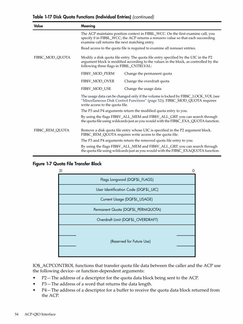
Table 1-17 Disk Quota Functions (Individual Entries) (continued)
MeaningValue
The ACP maintains position context in FIB$L_WCC. On the first examine call, youspecify 0 in FIB$L_WCC; the ACP returns a nonzero value so that each succeedingexamine call returns the next matching entry.Read access to the quota file is required to examine all nonuser entries.
Modify a disk quota file entry. The quota file entry specified by the UIC in the P2argument block is modified according to the values in the block, as controlled by thefollowing three flags in FIB$L_CNTRLVAL:
FIB$C_MOD_QUOTA
Change the permanent quotaFIB$V_MOD_PERM
Change the overdraft quotaFIB$V_MOD_OVER
Change the usage dataFIB$V_MOD_USE
The usage data can be changed only if the volume is locked by FIB$C_LOCK_VOL (see“Miscellaneous Disk Control Functions” (page 52)). FIB$C_MOD_QUOTA requireswrite access to the quota file.The P3 and P4 arguments return the modified quota entry to you.By using the flags FIB$V_ALL_MEM and FIB$V_ALL_GRP, you can search throughthe quota file using wildcards just as you would with the FIB$C_EXA_QUOTA function.
Remove a disk quota file entry whose UIC is specified in the P2 argument block.FIB$C_REM_QUOTA requires write access to the quota file.The P3 and P4 arguments return the removed quota file entry to you.By using the flags FIB$V_ALL_MEM and FIB$V_ALL_GRP, you can search throughthe quota file using wildcards just as you would with the FIB$C_EXAQUOTA function.
FIB$C_REM_QUOTA
Figure 1-7 Quota File Transfer Block
Flags Longword (DQF$L_FLAGS)
User Identification Code (DQF$L_UIC)
Current Usage (DQF$L_USAGE)
Permanent Quota (DQF$L_PERMQUOTA)
Overdraft Limit (DQF$L_OVERDRAFT)
(Reserved for Future Use)
31 0
IO$_ACPCONTROL functions that transfer quota file data between the caller and the ACP usethe following device- or function-dependent arguments:• P2—The address of a descriptor for the quota data block being sent to the ACP.• P3—The address of a word that returns the data length.• P4—The address of a descriptor for a buffer to receive the quota data block returned from
the ACP.
54 ACP-QIO Interface

1.7 I/O Status BlockFigure 1-8 shows the I/O status block (IOSB) for ACP--QIO functions. Appendix A lists the statusreturns for these functions. (The OpenVMS system messages documentation provides explanationsand suggested user actions for these returns.)The file ACP returns a completion status in the first longword of the IOSB. In an extend operation,the second longword is used to return the number of blocks allocated to the file. If a contiguousextend operation (FIB$V_ALCON) fails, the second longword is used to return the size of thefile after truncation.Values returned in the IOSB are most useful during operations in compatibility mode. Whenexecuting programs in the native mode, use the values returned in FIB locations.
Figure 1-8 IOSB Contents — ACP-QIO Functions
Not Used Status
+2
+4
IOSB
If an extend operation (including CREATE) was performed, IOSB+4 contains the number ofblocks allocated, or the largest available contiguous space if a contiguous extend operation failed.If a truncate operation was performed, IOSB+4 contains the number of blocks added to the filesize to reach the next cluster boundary.
1.7 I/O Status Block 55

56

2 Disk DriversThis chapter describes the use of disk drivers that support the disk devices listed in the SoftwareProduct Description for the OpenVMS Operating System (SPD 82.35.xx). The chapter also includesdescriptions of many of the supported disks and controllers; however, not all supported devicesare described here. For the definitive list of supported devices, see Software Product Descriptionfor the OpenVMS Operating SystemAll disk drivers support Files-11 On-Disk Structure Level 1 and Level 2 file structures. Access tothese file structures is through the DCL commands INITIALIZE and MOUNT, followed by theRMS calls described in the OpenVMS Record Management Utilities Reference Manual. Files inRT-11 format can be read or written with the file exchange facility EXCHANGE.
2.1 Driver FeaturesDisk drivers provide the following features:• Multiple controllers of the same type (except RB730), for example, more than one MBA or
RK611 can be used on the system• Multiple disk drives per controller (the exact number depends on the controller)• Different types of disk drives on a single controller• Static dual porting (MBA drives only)• Overlapped seeks (except RL02, RX01, RX02, and TU58)• Data checks on a per-request, per-file, or per-volume basis (except RX01 and RX02)• Full recovery from power failure for online disk drives with volumes mounted• Extensive error recovery algorithms, such as error code correction and offset (except RB02,
RL02, RX01, RX02, and TU58); for DSA disks, these algorithms are implemented in thecontroller
• Dynamic, as well as static, bad block handling• Logging of device errors in a file that can be displayed by field service personnel or customer
personnel• Online diagnostic support for drive level diagnostics• Multiple-block, noncontiguous, virtual I/O operations at the driver level• Logical-to-physical sector translation (RX01 and RX02 only)The following sections describe these features in greater detail.
2.1.1 Data CheckA data check is made after successful completion of a read or write operation and, except for theTU58, compares the data in memory with the data on disk to make sure they match.Disk drivers support data checks at the following levels:• Per request—You can specify the data check function modifier (IO$M_DATACHECK) on
a read logical block, write logical block, read virtual block, write virtual block, read physicalblock, or write physical block operation. IO$M_DATACHECK is not supported for the RX01and RX01 drivers.
• Per volume—You can specify the characteristics “data check all reads” and “data check allwrites” when the volume is mounted. The HP OpenVMS DCL Dictionary describes volumemounting and dismounting. The HP OpenVMS System Services Reference Manual describesthe Mount Volume ($MOUNT) and Dismount Volume ($DISMOUNT) system services.
• Per file—You can specify the file access attributes “data check on read” and “data check onwrite.” File access attributes are specified when the file is accessed. Chapter 1 of this manualand the OpenVMS Record Management Services Reference Manual describe file access.
2.1 Driver Features 57

Offset recovery is performed during a data check, but error code correction (ECC) is not performed(see “Error Recovery” (page 58)). For example, if a read operation is performed and an ECCcorrection is applied, the data check would fail even though the data in memory is correct. Inthis case, the driver returns a status code indicating that the operation was completed successfully,but the data check could not be performed because of an ECC correction.Data checks on read operations are extremely rare, and you can either accept the data as is, treatthe ECC correction as an error, or accept the data but immediately move it to another area onthe disk volume.A data check operation directed to a TU58 does not compare the data in memory with the dataon tape. Instead, either a read check or a write check operation is performed (see “Read” (page 63)and “Write” (page 64)).
2.1.2 Effects of a Failure During an I/O Write OperationThe operating system ensures that when an I/O write operation returns a successful completionstatus, the data is available on the disk or tape media. Applications that must guarantee thesuccessful completion of a write operation can verify that the data is on the media by specifyingthe data check function modifier IO$M_DATACHECK. Note that the IO$M_DATACHECK datacheck function, which compares the data in memory with the data on disk, affects performancebecause the function incurs the overhead of an additional read operation to the media.If a system failure occurs while a multiple-block write operation is in progress, the operatingsystem does not guarantee the successful completion of the write operation. (OpenVMS doesguarantee single-block write operations to DSA drives.) When a failure interrupts a writeoperation, the data may be left in any one of the following conditions:• The new data is written completely to the disk blocks on the media, but a completion status
was not returned before the failure.• The new data is partially written to the media so that some of the disk blocks involved in
the I/O contain the data from the write operation in progress, and the remainder of the blockscontain the data that was present before the write operation.
• The new data was never written to the disk blocks on the media.To guarantee that a write operation either finishes successfully or (in the event of failure) isredone or rolled back as if it were never started, use additional techniques to ensure datacorrectness and recovery. For example, using database journaling and recovery techniques allowsapplications to recover automatically from failures such as the following:• Permanent loss of the path between a CPU data buffer containing the data being written
and the disk being written to during a multiple-block I/O operation. Communication pathloss can occur due to node or controller failure or a failure of node-to-node communications.
• Failure of a CPU (such as a system failure, system halt, power failure, or system shutdown)during a multiple-block write operation.
• Mistaken deletion of a file.• Corruption of file system pointers.• File corruption due to a software error or incomplete bucket write operation to an indexed
file.• Cancellation of an in-progress multiple-block write operation.
2.1.3 Error RecoveryError recovery in the operating system is aimed at performing all possible operations to completean I/O operation successfully. Error recovery operations fall into the following categories:• Handling special conditions such as power failure and interrupt timeout.• Retrying nonfatal controller and drive errors. For DSA and SCSI disks, this function is
implemented by the controller.
58 Disk Drivers

• Applying error correction information (not applicable for RB02, RL02, RX01, RX02, andTU58 drives). For DSA and SCSI disks, error correction is implemented by the controller.
• Offsetting read heads to try to obtain a stronger recorded signal (not applicable for RB02,RL02, RB80, RM80, RX01, RX02, and TU58 drives). For DSA and SCSI disks, this function isimplemented by the controller.
The error recovery algorithm uses a combination of these four types of error recovery operationsto complete an I/O operation:• Power failure recovery consists of waiting for mounted drives to spin up and come on line,
followed by reexecution of the I/O operation that was in progress at the time of the powerfailure.
• Device timeout is treated as a nonfatal error. The operation that was in progress when thetimeout occurred is reexecuted up to eight times before a timeout error is returned.
• Nonfatal controller/drive errors are executed up to eight times before a fatal error is returned.• All normal error recovery procedures (nonspecial conditions) can be inhibited by specifying
the inhibit retry function modifier (IO$M_INHRETRY). If any error occurs and this modifieris specified, the virtual, logical, or physical I/O operation is immediately terminated, and afailure status is returned. This modifier has no effect on power recovery and timeout recovery.
2.1.4 SCSI Disk Class DriverAlthough SCSI disks do not conform to DSA, they do support the following error recoveryfeatures:• Static and dynamic bad block replacement (BBR)• Error correction code (ECC)• Reexecution of read or write operations within the SCSI drive• Reexecution of read or write operations by the SCSI disk class driverAll SCSI disks supplied by HP implement the REASSIGN BLOCKS command, which relocatesdata for a specific logical block to a different physical location on the disk. The SCSI disk classdriver reassigns the block in the following instances: (1) when the retry threshold is exceededduring an attempt to read or write a block of data on the disk or (2) when an irrecoverable erroroccurs during a write operation.Unlike DSA, there is no forced error flag in SCSI. Blocks that produce irrecoverable errors duringread operations are not reassigned in order to prevent undetected loss of user data. Instead, theSCSI disk class driver returns the SS$_PARITY status whenever a read operation results in anirrecoverable error.
2.1.5 Audio Extensions to the SCSI Disk Class DriverThe operating system provides audio functionality through the SCSI disk class driver. The SCSIdisk class driver provides an interface by which the audio commands can be issued to SCSIdevices. These commands can be issued through the QIO function call. This functionality isavailable for devices, such as CD-ROMs that have audio capability.The IO$_AUDIO function code allows the SCSI disk class driver to process the SCSI audiocommands. An Audio Control Block (AUCB) must be defined for a specific SCSI audio command.This AUCB provides the SCSI disk class driver with command-specific arguments and controlinformation. An application program must use the IO$_AUDIO function code and provide theAUCB for the SCSI driver to process the audio commands.For more information, see $QIO Interface to Audio Functionality of the SCSI Disk Class Driver.
2.1 Driver Features 59

2.2 Disk Driver Device InformationYou can obtain information on all disk device characteristics by using the Get Device/VolumeInformation ($GETDVI) system service (see the HP OpenVMS System Services Reference Manual).$GETDVI returns disk characteristics when you specify the item codes DVI$_DEVCHAR andDVI$_DEVCHAR2.See the Help files for disk device characteristics.
2.3 Disk Function CodesDisk drivers can perform logical, virtual, and physical I/O functions. Foreign-mounted devicesdo not require privilege to perform logical and virtual I/O requests.Logical and physical I/O functions allow access to volume storage and require only that theissuing process have access to the volume; however, DSA disks and the Shadow disk class driver(DUDRIVER) do not accept physical QIO data transfers or seek operations.
NOTE: The results of logical and physical I/O operations are unpredictable if an ancillary controlprocess (ACP) or extended QIO processing (XQP) is present.
Virtual I/O functions require an ACP for Files-11 On-Disk Structure Level 1 files or an XQP forFiles-11 On-Disk Structure Level 2 files. Virtual I/O functions must be executed in a prescribedorder. First, you create and access a file, then you write information to that file, and lastly youdeaccess the file. Subsequently, when you access the file, you read the information and thendeaccess the file. Delete the file when the information is no longer useful.The volume to which a logical or virtual function is directed must be mounted for the functionactually to be executed. If it is not mounted, either a “device not mounted” or “invalid volume”status is returned in the I/O status block.Table 2-1 lists the logical, virtual, and physical disk I/O functions and their function codes.Chapter 1 describes the QIO level interface to the disk device ACP.
Table 2-1 Disk I/O Functions
FunctionFunction ModifiersType1ArgumentsFunction Code
Search a directory for aspecified file and access the fileif found.
IO$M_CREATEIO$M_ACCESS
VP1, [P2],[P3],[P4], [P5]
IO$_ACCESS
Perform miscellaneous controlfunctions.
IO$M_DMOUNTVP1,[P2],[P3],[P4],[P5]
IO$_ACPCONTROL
Clear volume valid; make DSAunits available.
PIO$_AVAILABLE
Create a directory entry or afile.
IO$M_CREATEIO$M_ACCESSIO$M_DELETE
VP1,[P2],[P3],[P4],[P5]
IO$_CREATE
Deaccess a file and, if specified,write final attributes in the fileheader.
VP1,[P2],[P3],[P4],[P5]
IO$_DEACCESS
Remove a directory entry or fileheader, or both.
IO$M_DELETEVP1,[P2],[P3],[P4],[P5]
IO$_DELETE
Set density (RX02 only).PP1IO$_FORMAT
Modify the file attributes orallocation, or both.
VP1,[P2],[P3],[P4],[P5]
IO$_MODIFY
60 Disk Drivers

Table 2-1 Disk I/O Functions (continued)
FunctionFunction ModifiersType1ArgumentsFunction Code
Update UCB fields if RX02;initialize volume valid on otherdevices. Bring DSA units online.
PIO$_PACKACK
Read logical block.IO$M_DATACHECK3
IO$M_INHRETRYLP1,P2,P3IO$_READLBL2
Read physical block.5IO$M_DATACHECK3
IO$M_INHRETRYIO$M_INHSEEK4
PP1,P2,P3IO$_READPBLK2
Read virtual block.IO$M_DATACHECK3
IO$M_INHRETRYVP1,P2,P3IO$_READVBLK2
Search for specified block orsector (only for TU58).
PP1IO$_SEARCH
Seek to specified cylinder.5PP1IO$_SEEK
Sense the device-dependentcharacteristics and return themin the I/O status block.
PIO$_SENSECHAR
Sense the device-dependentcharacteristics and return themin the I/O status block.
LIO$_SENSEMODE
Specifies a preferred path forDSA disks.
IO$M_FORCEPTHPP1IO$_SETPRFPATH
Clear volume valid; make DSAunits available and spin downthe volume.
PIO$_UNLOAD
Verify data written to disk by aprevious write QIO.3
PP1,P2,P3IO$_WRITECHECK 2
Write logical block.IO$M_DATACHECK3
IO$M_ERASEIO$M_INHRETRY
LP1,P2,P3IO$_WRITELBLK2
Write physical block.5IO$M_DATACHECK3
IO$M_ERASEIO$M_INHRETRYIO$M_INHSEEK 4
IO$M_DELDATA 6
PP1,P2,P3IO$_WRITEPBLK2
Write virtual block.IO$M_DATACHECK3
IO$M_ERASEIO$M_INHRETRY
VP1,P2,P3IO$_WRITEVBLK2
1 V = virtual; L = logical; P = physical.2 On OpenVMS Alpha, P1 supports a 64-bit address.3 Not for RX01 and RX02 disks.4 Not for TU58, TX01, RX02, RB02 and RL02 drives.5 Not for DSA and SCSI disks.6 RX02 only.
The function-dependent arguments for IO$_CREATE, IO$_ACCESS, IO$_DEACCESS,IO$_MODIFY, and IO$_DELETE are as follows:• P1—The address of the file information block (FIB) descriptor.• P2—The address of the file name string descriptor (optional). If specified, the name is entered
in the directory specified by the FIB.
2.3 Disk Function Codes 61

• P3—The address of the word that is to receive the length of the resulting file name string(optional).
• P4—The address of a descriptor for a buffer that is to receive the resulting file name string(optional).
• P5—The address of a list of attribute descriptors (optional). If specified, the indicatedattributes are read (IO$_ACCESS) or written (IO$_CREATE, IO$_DEACCESS, andIO$_MODIFY).
See Chapter 1 for more information on these functions.The function-dependent arguments for IO$_READVBLK, IO$_READLBLK, IO$_WRITEVBLK,and IO$_WRITELBLK are as follows:• P1—The starting virtual address of the buffer that is to receive the data from a read operation;
or, in the case of a write operation, the virtual address of the buffer that is to be written onthe disk. On OpenVMS Alpha, P1 can be a 64-bit address.
• P2—The number of bytes that are to be read from the disk, or written from memory to thedisk. An even number must be specified if the controller is an RK611, RL11, RX211, or UDA50.
• P3—The starting virtual/logical disk address of the data to be transferred in a read operation;or, in a write operation, the disk address of the area that is to receive the data.In a virtual read or write operation, the address is expressed as a block number within thefile, that is, block 1 of the file is virtual block 1. (Virtual block numbers are converted tological block numbers using mapping windows that are set up by the file system ACPprocess.)In a logical read or write operation, the address is expressed as a block number relative tothe start of the disk. For example, the first sector on the disk contains block 0 (or at least thebeginning of block 0).
The function-dependent arguments for IO$_WRITEVBLK, IO$_WRITELBLK, andIO$_WRITEPBLK functions that include the IO$M_ERASE function modifier are as follows:• P1——The starting virtual address of the buffer that contains a 4-byte, user-specified erase
pattern. If the P1 address is 0, a longword of 0 is used for the erase pattern. If the P1 addressis nonzero, the contents of the 4 bytes starting at that address is used as the erase pattern.HP recommends that the user specify a P1 address of 0 to lower system overhead. OnOpenVMS Alpha, P1 can be a 64-bit address.
NOTE: DSA disk controllers provide controlled, assisted erasing for the IO$M_ERASEmodifier (with virtual and logical write functions) only when the erase pattern is all zeros.If a nonzero erase pattern is used, there is a significant performance degradation with thesedisks. DSA disks do not accept physical QIO transfers.
• P2—The number of bytes of erase pattern to write to the disk. The number specified isrounded up to the next highest block boundary (512 bytes).
• P3—The starting virtual, logical, or physical disk address of the data to be erased.The function-dependent arguments for IO$_WRITECHECK, IO$_READPBLK, andIO$_WRITEPBLK are as follows:• P1—The starting virtual address of the buffer that is to receive the data in a read operation;
or, in a write operation, the starting virtual address of the buffer that is to be written on thedisk. Passed by reference. On OpenVMS Alpha and OpenVMS Integrity server, P1 can bea 64-bit address.
• P2—The number of bytes that are to be read from the disk, or written from memory to thedisk. Passed by value. An even number must be specified if the controller is an RK611, RL11,or UDA50.
• P3—The starting physical disk address of the data to be read in a read operation; or, in awrite operation, the starting physical address of the disk area that is to receive the data.
62 Disk Drivers

Passed by value. The address is expressed as sector, track, and cylinder in the format shownin Figure 2-1. (On the RX01 and RX02, the high word specifies the track number rather thanthe cylinder number.) Check the UCB of a currently mounted device to determine themaximum physical address value for that type of device.
NOTE: On the RB80 and RM80, do not address cylinders 560 and 561. These two cylindersare used for diagnostic testing only.
The function-dependent argument for IO$_SEARCH is as follows:• P1—The physical disk address where the tape is positioned. The address is expressed as
sector, track, and cylinder in the format shown in Figure 2-1.
Figure 2-1 Starting Physical Address
Cylinder Track SectorP3:
31 1516 78 0
P3:
31 1516 0
Track Sector
(Except RX01 and RX02)
(RX01 and RX02 Only)
The function-dependent argument for IO$_SEEK is as follows:• P1—The physical cylinder number where the disk heads are positioned. The address is
expressed in the format shown in Figure 2-2.
Figure 2-2 Physical Cylinder Number Format31 1516 0
Not Used Cylinder
The function-dependent argument for IO$_FORMAT is as follows:• P1—The density at which an RX02 diskette is reformatted (see “Set Density” (page 65)).
2.3.1 ReadThe read function reads data into a specified buffer from disk starting at a specified disk address.The operating system provides the following read function codes:• IO$_READVBLK—Read virtual block• IO$_READLBLK—Read logical block• IO$_READPBLK—Read physical blockIf a read virtual block function is directed to a volume that is mounted foreign, that function isconverted to read logical block. If a read virtual block function is directed to a volume that ismounted structured, the volume is handled in the same way as for a file-structured device.Three function-dependent arguments are used with these codes: P1, P2, and P3. These argumentsare described in “Disk Function Codes” (page 60).The data check function modifier (IO$M_DATACHECK) can be used with all read functions. Ifthis modifier is specified, a data check operation is performed after the read operation completes.A data check operation is also performed if the volume that has been read, or the volume on
2.3 Disk Function Codes 63
which the file resides (virtual read) has the characteristic “data check all reads.” Furthermore, adata check is performed after a virtual read if the file has the attribute “data check on read.” TheRX01 and RX02 drivers do not support the data check function.If IO$M_DATACHECK is specified with a read function code to a TU58, or if the volume readhas the characteristic “data check all reads,” a read check operation is performed. This alterscertain TU58 hardware parameters when the tape is read. (The read threshold in the data recoverycircuit is increased; if the tape has any weak spots, errors are detected.)The data check function modifier to a disk or tape can return five error codes in the I/O statusblock:
SS$_MEDOFLSS$_DRVERRSS$_CTRLERR
SS$_NORMALSS$_NONEXDRV
If no errors are detected, the disk or tape data is considered reliable.The inhibit retry function modifier (IO$M_INHRETRY) can be used with all read functions. Ifthis modifier is specified, all error recovery attempts are inhibited. IO$M_INHRETRY takesprecedence over IO$M_DATACHECK. If both are specified and an error occurs, there is noattempt at error recovery and no data check operation is performed. If an error does not occur,the data check operation is performed.
2.3.2 WriteThe write function writes data from a specified buffer to disk starting at a specified disk address.The operating system provides the following write function codes:• IO$_WRITEVBLK—Write virtual block• IO$_WRITELBLK—Write logical block• IO$_WRITEPBLK—Write physical blockIf a write virtual block function is directed to a volume that is mounted foreign, the function isconverted to write logical block. If a write virtual block function is directed to a volume that ismounted structured, the volume is handled in the same way as for a file-structured device.Three function-dependent arguments are used with these codes: P1, P2, and P3. These argumentsare described in “Disk Function Codes” (page 60).The data check function modifier (IO$M_DATACHECK) can be used with all write operations.If this modifier is specified, a data check operation is performed after the write operationcompletes. A data check operation is also performed if the volume written, or the volume onwhich the file resides (virtual write), has the characteristic “data check all writes.” Furthermore,a data check is performed after a virtual write if the file has the attribute “data check on write.”The RX01 and RX02 drivers do not support the data check function.If IO$M_DATACHECK is specified with a write function code to a TU58, or if the volume writtenhas the characteristic “data check all writes,” a write check operation is performed. The writecheck verifies data written on the tape. First, the specified data is written on the tape. Then thetape is reversed and the TU58 controller reads the data internally to perform a checksumverification. If the checksum verification is unsuccessful after eight attempts, the write checkoperation is aborted and an error status is returned.The inhibit retry function modifier (IO$M_INHRETRY) can be used with all write functions. Ifthat modifier is specified, all error recovery attempts are inhibited. IO$M_INHRETRY takesprecedence over IO$M_DATACHECK. If both IO$M_INHRETRY and IO$M_DATACHECK arespecified and an error occurs, there is no attempt at error recovery, and no data check operationis performed. If an error does not occur, the data check operation is performed. IO$M_INHRETRYhas no effect on DSA disks.
64 Disk Drivers

The write deleted data function modifier (IO$M_DELDATA) can be used with the write physicalblock (IO$_WRITEPBLK) function to the RX02. If this modifier is specified, a deleted data addressmark instead of the standard data address mark is written preceding the data. Otherwise, theoperation of the IO$_WRITEPBLK function is the same; write data is transferred to the disk.When a successful read operation is performed on this data, the status code SS$_RDDELDATAis returned in the I/O status block rather than the usual SS$_NORMAL status code.The IO$M_ERASE function modifier can be used with all write function codes to erase auser-selected part of a disk. This modifier propagates an erase pattern through the specifiedrange. “Disk Function Codes” (page 60) describes the write function arguments to be used withIO$M_ERASE.
2.3.3 Sense ModeSense mode operations obtain current disk device-dependent characteristics that are returnedto the caller in the second longword of the I/O status block (see Figure 2-6). The operating systemprovides the following function codes:• IO$_SENSEMODE—Sense characteristics• IO$_SENSECHAR—Sense characteristicsIO$_SENSEMODE is a logical function. IO$_SENSECHAR is a physical I/O function and requiresthe access privilege necessary to perform physical I/O. No device- or function-dependentarguments are used with either function.
2.3.4 Set DensityThe set density function assigns a new density to an entire RX02 diskette. The diskette is alsoreformatted: new data address marks are written (single or double density) and all data fieldsare zeroed. Set density is a physical I/O function and requires the access privilege necessary toperform physical I/O. The following function code is provided:• IO$_FORMATIO$_FORMAT takes the following function-dependent argument:• P1—The density at which the diskette is reformatted:
— 0 = single density (default)— 1 = single density— 2 = double density
The set density operation should not be interrupted before it is completed (about 15 seconds). Ifthe operation is interrupted, the resulting diskette might contain illegal data address marks inboth densities. The diskette must then be completely reformatted and the function reissued.
2.3.5 SearchThe search function positions a TU58 magnetic tape to the block specified. Search is a physicalI/O function and requires the access privilege necessary to perform physical I/O. The operatingsystem provides a single function code:• IO$_SEARCHThis function code takes the following function-dependent argument:• P1—Specifies the block where the read/write head is positioned. The low byte contains the
sector number in the range 0 to 127; the high byte contains the track number in the range 0to 3.
IO$_SEARCH can save time between read and write operations. For example, nearly 30 secondsare required to completely rewind a tape. If the last read or write operation is near the end ofthe tape and the next operation is near the beginning of the tape, the search operation can beginafter the last operation completes, and the tape rewinds while the process is otherwise occupied.
2.3 Disk Function Codes 65

(The search QIO is not completed until the search is completed. Consequently, if a $QIOW systemservice request is issued, the process is held up until the search is completed.)
2.3.6 Pack AcknowledgeThe pack acknowledge function sets the volume valid bit for all disk devices. Pack acknowledgeis a physical I/O function and requires the access privilege to perform physical I/O. If directedto an RX02 disk, pack acknowledge also determines the diskette density and updates thedevice-dependent information returned by $GETDVI item codes DVI$_CYLINDERS,DVI$_TRACKS, DVI$_SECTORS, DVI$_DEVTYPE, DVI$_CLASS, and DVI$_MAXBLOCK. Ifdirected to a DSA disk, pack acknowledge also sends the online packet to the controller. Thefollowing function code is provided:• IO$_PACKACKThis function code takes no function-dependent arguments.IO$_PACKACK must be the first function issued when a volume (pack, cartridge, or diskette)is placed in a disk drive. IO$_PACKACK is issued automatically when the DCL commandsINITIALIZE or MOUNT are issued.For DSA disks, the IO$_PACKACK function locks the drive's port selector on the port thatinitiated the pack acknowledge function.In addition, the IO$_PACKACK function updates device-dependent information about DSAdisks returned by $GETDVI.
2.3.7 UnloadThe unload function clears the volume valid bit for all disk drives, makes DSA disks available,and issues an unload command to the drive (spins down the volume). The unload functionreverses the function performed by pack acknowledge (see “Pack Acknowledge” (page 66)).The following function code is provided:• IO$_UNLOADThis function takes no function-dependent arguments.
2.3.8 AvailableThe available function clears the volume valid bit for all disk drives; that is, it reverses the functionperformed by pack acknowledge (see “Pack Acknowledge” (page 66)). No unload function isissued to the drive; therefore, those drives capable of spinning down do not spin down. Thefollowing function code is provided:• IO$_AVAILABLEThis function takes no function-dependent arguments.
2.3.9 SeekThe seek function directs the read/write heads to move to the cylinder specified in the P1 argument(see “Disk Function Codes” (page 60) and Figure 2-2).
2.3.10 Write CheckThe write check function verifies that data was written to disk correctly. The data to be checkedis addressed using physical disk addressing (sector, track, and cylinder) (see Figure 2-1). If therequest is directed to a DSA disk, you must specify a logical block number, even thoughIO$_WRITECHECK is a physical I/O function. The following function code is provided:• IO$_WRITECHECKA write QIO must be used to write data to disk before you enter this command.IO$_WRITECHECK then reads the same block of data and compares it with the data in the
66 Disk Drivers

specified buffer. Three function-dependent arguments are used with this code: P1, P2, and P3.These arguments are described in “Disk Function Codes” (page 60).IO$_WRITECHECK is similar to the IO$M_DATACHECK function modifier for write QIOs,except that IO$_WRITECHECK does not write the data to disk; it is specified after data is writtenby a separate write QIO. Nonprivileged processes can use the IO$M_DATACHECK modifierwith IO$_WRITEVBLK (which does not require access privilege) to determine whether data iswritten correctly. The RX01 and RX02 drivers do not support the write check function.The write check function and the data check function modifier to a TU58 can return six errorcodes in the I/O status block: SS$_NORMAL, SS$_CTRLERR, SS$_DRVERR, SS$_MEDOFL,SS$_NONEXDRV, and SS$_WRTLCK.
2.3.11 Audio ExtensionsThe OpenVMS operating system provides audio functionality through the SCSI disk class driver.The SCSI disk class driver provides an interface by which the audio commands can be issued toSCSI devices. The audio commands can be issued through the QIO function call. This functionalityis available for devices, such as CD-ROMs which have audio capability.The function code IO$_AUDIO allows the SCSI disk class driver to process the SCSI audiocommands. An Audio Control Block (AUCB) must be defined for a specific SCSI audio command.The AUCB provides the SCSI disk class driver with command-specific arguments and controlinformation. An application program must use the IO$_AUDIO function code and provide theAUCB in order for the SCSI driver to process the audio commands.For more information, seeThis section describes the SCSI disk class driver audio commands and the $QIO interface bywhich the operating system provides audio functionality to the SCSI disk.Table 2-2 lists the SCSI audio commands supported by the SCSI disk class driver.
Table 2-2 SCSI Disk Class Driver Audio Commands
DescriptionAudio Function Code1Command
Requests the CD-ROM to begin an audio playback operation.The two required command arguments specify absolutestarting and ending addresses of the playback in terms ofminutes, seconds, and frame (MSF).
AUDIO_PLAY_AUDIO_MSF (5)Play AudioMSF
Requests the CD-ROM to begin an audio playback operation.The two required command arguments specify the startingand ending tracks of the playback in terms of track numberand index.
AUDIO_PLAY_AUDIO_TRACK (6)Play AudioTrack
Requests the CD-ROM to begin an audio playback operation.The two required command arguments specify the startinglogical block address (LBA) and the transfer count, in blocks,of the playback.
AUDIO_PLAY_AUDIO (4)Play Audio
Requests the CD-ROM to suspend any active audiooperations. In response, the CD-ROM enters the hold-trackstate, muting the audio output after playing the currentblock.
AUDIO_PAUSE (0)Pause
Requests the CD-ROM to resume any active audiooperations. In response, the CD-ROM exits the hold-trackstate and resumes playback at the block following the lastblock played.
AUDIO_RESUME (1)Resume
Requests from the CD-ROM the status of the currently activeplayback operation, as well as the state of the current block.The Get Status command corresponds to the SCSI II ReadSub-channel command (READ SUBQ).
AUDIO_GET_STATUS (9)Get Status
2.3 Disk Function Codes 67

Table 2-2 SCSI Disk Class Driver Audio Commands (continued)
DescriptionAudio Function Code1Command
Requests the CD-ROM to adjust the output channel selectionand volume settings for ports 0 through 3. The Set Volumecommand corresponds to the SCSI II Mode Select commandfor the CD-ROM Audio Control Parameters page.
AUDIO_SET_VOLUME (11)Set Volume
Requests from the CD-ROM the output channel selectionand volume settings for ports 0 through 3. The Get Volumecommand corresponds to the SCSI II Mode Sense commandfor the CD-ROM Audio Control Parameters page.
AUDIO_GET_VOLUME (12)Get Volume
Prevents the removal of the CD caddy from the CD-ROMdrive.
AUDIO_PREVENT_REMOVAL (2)PreventRemoval
Allows the removal of the CD caddy from the CD-ROMdrive.
AUDIO_ALLOW_REMOVAL (3)Allow Removal
Requests from the CD-ROM a list of each track on the disk,including information about the audio or data contents ofeach track. Applications that require a detailed knowledgeof the organization of a CD-ROM can use this function toobtain that information. The Get TOC command correspondsto the SCSI II Read TOC command.
AUDIO_GET_TOC (10)Get TOC
1 Symbolic values for the function codes of SCSI audio commands are defined in SYS$EXAMPLES:CDVERIFY.C.Numeric values appear within parentheses in this table column.
2.3.11.1 $QIO Interface to Audio Functionality of the SCSI Disk Class DriverTo employ the audio functions of the RRD42 CD-ROM reader, the application program issuesa call to the $QIO system service using the following format:status=SYS$QIO ([efn] ,[chan] ,func [,iosb] [,astadr] [,astprm] [,p1] [,p2] [,p3] [,p4] [,p5] [,p6])
Arguments
[efn][chan][iosb][astadr][astprm]These arguments apply to the $QIO system service completion, not to device interrupt actions.For an explanation of these arguments, see the description of the $QIO system service in the HPOpenVMS System Services Reference Manual.funcThe IO$_AUDIO function code allows the SCSI disk class driver to process SCSI audio commands.p1Address of an audio control block (AUCB). The $QIO system service passes a SCSI audio commandand command-specific control information to the SCSI disk class driver in the AUCB structure(see “Defining an Audio Control Block (AUCB)” (page 69)).p2Size of the AUCB.
68 Disk Drivers

2.3.11.2 Defining an Audio Control Block (AUCB)An application program that issues a call to the $QIO system service that specifies the IO$_AUDIOfunction code in the func argument must supply the address of an AUCB structure in the p1argument and its size in the p2 argument.An AUCB defines a specific SCSI audio command and provides the SCSI disk class driver withcommand-specific arguments and control information. Table 2-3 defines the fields that appearin an AUCB; these fields are shown in Figure 2-3. See SYS$EXAMPLES:CDROM_AUDIO.C fora code example that shows how an AUCB is defined in the C programming language.
Figure 2-3 Audio Control Block (AUCB)
AUCB Version Number Audio Function Code
Argument 1
Argument 2
Argument 3
Reserved
Operating System Command Status
Destination Buffer Transfer Count
Destination Buffer Count
Destination Buffer Address
Reserved
Sense Data Buffer Transfer Count (optional)
Sense Data Buffer Count (optional)
Sense Data Buffer Address (optional)
SCSI Command Status (optional)
0
4
8
12
16
20
24
28
32
36
40
44
48
52
Table 2-3 Contents of AUCB
UseField
Numeric or symbolic code representing the audio function desired by the application program.(See Table 2-2.) The application program must provide a valid audio function code for eachoperation.
Audio FunctionCode
Version of the AUCB and SCSI disk class driver audio interface. For the current version of theinterface the value of this field should be 1. This field must never contain a zero.
AUCB VersionNumber
This field is audio command-specific and contains the first argument of the function as follows:Argument 1
Field ContentsAudio Function Code1
Starting Frames|(Sec shifted left 8 bits)|(Min shifted left16 bits)
AUDIO_PLAY_AUDIO_MSF (5)
Starting (Track shifted left 8 bits) |IndexAUDIO_PLAY_AUDIO_TRACK (6)
Starting logical block address.AUDIO_PLAY_AUDIO (4)
0 if LBA format, 1 if MSF format. See the SCSI IIspecification for information about these formats.
AUDIO_GET_STATUS (9)
2.3 Disk Function Codes 69

Table 2-3 Contents of AUCB (continued)
UseField
Longword representing the values to be used todetermine the new output channel selection and volumesettings for CD-ROM ports 0 through 3. Figure 2-4 showsthe format of this longword. Note that many CD-ROMdrives do not support ports 2 and 3.
AUDIO_SET_VOLUME (11)
Longword to receive the current values determiningoutput channel selection and volume settings forCD-ROM ports 0 through 3. Figure 2-4 shows the formatof this longword. Note that many CD-ROM drives donot support ports 2 and 3.
AUDIO_GET_VOLUME (12)
0 if LBA format, 1 if MSF format. See the SCSI IIspecification for information about these formats.
AUDIO_GET_TOC (10)
This field is audio command-specific and contains the second argument of the function as follows:Argument 2
Field ContentsAudio Function Code1
Starting frames|(sec shifted left 8 bits)|( min shifted left16 bits)
AUDIO_PLAY_AUDIO_MSF (5)
Ending(track shifted left 8 bits)|indexAUDIO_PLAY_AUDIO_TRACK (6)
Transfer count in number of contiguous blocks to beplayed
AUDIO_PLAY_AUDIO (4)
Starting trackAUDIO_GET_TOC (10)
Must be zero.Reserved
Address of the application program's buffer from which the status from a GET_STATUS orGET_TOC function is returned.
DestinationBuffer Address
Size, in bytes, of the destination buffer specified in the Destination Buffer Address field. For theGET_STATUS function, this field must contain the value 48 to receive complete status information.For the GET_TOC function, this field must contain the value 804 to receive full status. The SCSIdisk class driver truncates the status data, if the destination buffer size is smaller than the size ofthe data.
DestinationBuffer Count
The SCSI disk class driver returns to this field the actual number of bytes transferred to the bufferspecified in the Destination Buffer Address field.Before accessing data returned by the GET_TOC or GET_STATUS commands, an applicationprogram must check the contents of this field to determine precisely how many bytes werereturned by the CD-ROM.The application program initializes this field to zero.
DestinationBuffer TransferCount
Completion status of the SCSI audio function. This value is also returned in the I/O status blockof specified in the iosb argument to the $QIO system service call. See Table 2-4 for a descriptionof these status codes.The application program initializes this field to zero.
OperatingSystemCommand Status
SCSI status of the current operation. The SCSI disk class driver returns the SCSI status byte forthe SCSI audio command described by this AUCB in the low byte of the low-order word of thisfield. It returns the sense key in the low byte of the high-order word. See the SCSI specificationfor information regarding SCSI status and SCSI sense keys.The application program initializes this field to zero.
SCSI CommandStatus (optional)
Address of buffer to which the SCSI disk class driver returns sense data when errors occur duringaudio function execution. When this field is specified, in the event of a check condition on anAudio command, the SCSI disk class driver automatically issues a Request Sense command toretrieve the Sense Key/Sense Data from the target. The target returns this data to the bufferspecified in this field before the failing $QIO audio function completes.
Sense DataBuffer Address(optional)
70 Disk Drivers

Table 2-3 Contents of AUCB (continued)
UseField
Size, in bytes, of the buffer specified in the Sense Data Buffer Address field. During request senseprocessing, the target device truncates the sense data to fit in this buffer.
Sense DataBuffer Count(optional)
Actual number of bytes of sense data returned to the application in the buffer specified in theSense Data Buffer Address field.The application program initializes this field to zero.
Sense DataBuffer TransferCount (optional)
Must be zero.Reserved
1 For any function code not listed in this table, this field contains a zero.
The output channel selection and volume settings for CD-ROM ports as used by the SET_VOLUMEfunction appear as shown in Figure 2-4.
2.3.11.3 Error Handling in Applications Using SCSI Audio FunctionsAs indicated in Table 2-3, the AUCB provides for three levels of error status reporting:• Condition values, returned in the Operating System Command Status field of the AUCB,
as well as in the I/O status block of specified in the iosb argument to the $QIO system servicecall. (See Table 2-4 for a description of these status codes.)If this status is SS$_NORMAL, the function has completed without error. If the status is notSS$_NORMAL, the application program should check the SCSI Command Status field andthe Sense Data buffer to fully determine the cause of the failure.
Figure 2-4 Output Channel Selection and Volume Settings for CD-ROM Ports as Used by theSET_VOLUME Function
Volume Output Selection Output SelectionVolume
31 23 15 7 0
Port 1 or 3 Port 0 or 2
volume=00 (muted) to FF (maximum)output selection<7:4>=0output selection<3:0>=0000 (output muted on this channel)
0001 (connect audio channel 0 to this output port)0010 (connect audio channel 1 to this output port)0011 (connect audio channels 0 and 1 to this port)
• SCSI command status, returned in the SCSI Command Status field of the AUCB. The SCSIdisk class driver returns to this field SCSI status as well as the sense key in the event of acheck condition SCSI status. The sense key can be used to determine the first level of errorreporting supported by SCSI. See the SCSI specification for further information.
• Sense data, returned in the buffer specified in the Sense Data Buffer Address field of theAUCB. Sense data bytes are assigned as defined in the SCSI II specification. Sophisticatedprogrammers can use the data in this to obtain detailed information about the error-causingcondition.
If the CD-ROM device is currently software-enabled (that is, the volume has been mounted) anda unit attention is detected, then mount verification is initiated by the driver. However, if theCD-ROM is not software-enabled, the event returns to the application issuing the Audio $QIOfunction.
2.3 Disk Function Codes 71
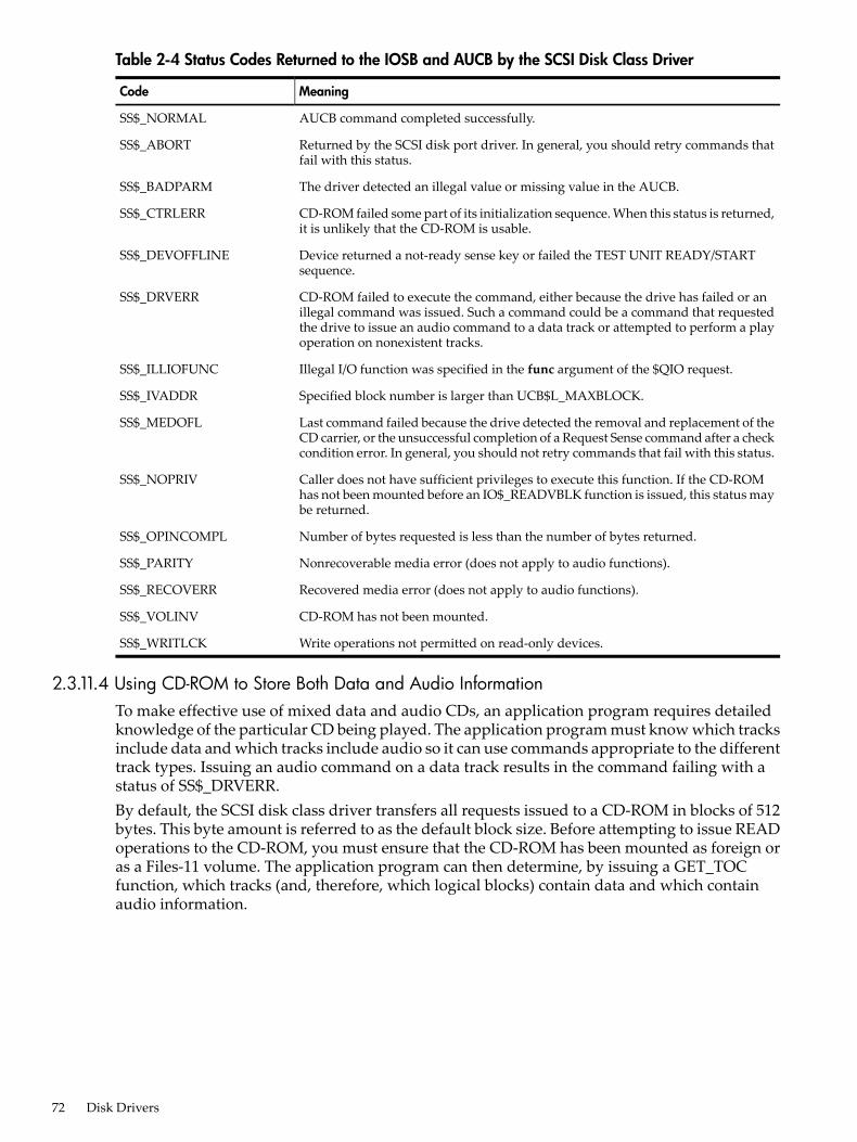
Table 2-4 Status Codes Returned to the IOSB and AUCB by the SCSI Disk Class Driver
MeaningCode
AUCB command completed successfully.SS$_NORMAL
Returned by the SCSI disk port driver. In general, you should retry commands thatfail with this status.
SS$_ABORT
The driver detected an illegal value or missing value in the AUCB.SS$_BADPARM
CD-ROM failed some part of its initialization sequence. When this status is returned,it is unlikely that the CD-ROM is usable.
SS$_CTRLERR
Device returned a not-ready sense key or failed the TEST UNIT READY/STARTsequence.
SS$_DEVOFFLINE
CD-ROM failed to execute the command, either because the drive has failed or anillegal command was issued. Such a command could be a command that requestedthe drive to issue an audio command to a data track or attempted to perform a playoperation on nonexistent tracks.
SS$_DRVERR
Illegal I/O function was specified in the func argument of the $QIO request.SS$_ILLIOFUNC
Specified block number is larger than UCB$L_MAXBLOCK.SS$_IVADDR
Last command failed because the drive detected the removal and replacement of theCD carrier, or the unsuccessful completion of a Request Sense command after a checkcondition error. In general, you should not retry commands that fail with this status.
SS$_MEDOFL
Caller does not have sufficient privileges to execute this function. If the CD-ROMhas not been mounted before an IO$_READVBLK function is issued, this status maybe returned.
SS$_NOPRIV
Number of bytes requested is less than the number of bytes returned.SS$_OPINCOMPL
Nonrecoverable media error (does not apply to audio functions).SS$_PARITY
Recovered media error (does not apply to audio functions).SS$_RECOVERR
CD-ROM has not been mounted.SS$_VOLINV
Write operations not permitted on read-only devices.SS$_WRITLCK
2.3.11.4 Using CD-ROM to Store Both Data and Audio InformationTo make effective use of mixed data and audio CDs, an application program requires detailedknowledge of the particular CD being played. The application program must know which tracksinclude data and which tracks include audio so it can use commands appropriate to the differenttrack types. Issuing an audio command on a data track results in the command failing with astatus of SS$_DRVERR.By default, the SCSI disk class driver transfers all requests issued to a CD-ROM in blocks of 512bytes. This byte amount is referred to as the default block size. Before attempting to issue READoperations to the CD-ROM, you must ensure that the CD-ROM has been mounted as foreign oras a Files-11 volume. The application program can then determine, by issuing a GET_TOCfunction, which tracks (and, therefore, which logical blocks) contain data and which containaudio information.
72 Disk Drivers

2.3.11.5 Programming Audio ApplicationsThe following list contains information useful in avoiding problems when writing code usingthe SCSI audio interfaces:• If you do not know the type of file system on the CD-ROM, you should mount the CD-ROM
as foreign and issue a $QIO request with the logical block I/O read function (IO$_READLBLK)to read individual data blocks. The default block size for all CD-ROMs is 512 bytes.
• When using the GET_TOC command to obtain CD-ROM address information in LBA format,be advised that the byte ordering of the returned data is in big-endian form.SYS$EXAMPLES:CDROM_AUDIO.C contains an example of how to perform this exchange.
• Before attempting to issue a $QIO request with the virtual block I/O read function(IO$_READVBLK) to the CD-ROM, ensure that the CD-ROM has been mounted. Typically,you have to foreign mount non-Files-11 disks. If an IO$_READVBLK $QIO request is issuedto an unmounted CD, the request fails with a status of SS$_NOPRIV.
2.4 I/O Status BlockFigure 2-5 shows the I/O status block (IOSB) for all disk device QIO functions except sense mode.Figure 2-6 shows the I/O status block for the sense mode function. Figure 2-6 lists the statusmessages for all functions and devices. (The OpenVMS system messages documentation providesexplanations and suggested user actions for these messages.)
Figure 2-5 IOSB Contents
Byte Count(LowOrder Word)
Byte Count(HighOrder Word)0
Status
31 1516 0
The byte count is a 32-bit integer that gives the actual number of bytes transferred to or from theprocess buffer.
Figure 2-6 IOSB Contents for the Sense Mode Function
Cylinders Tracks Sectors
0 Status
31 1516 78 0
The second longword of the I/O status block for the sense mode function returns informationabout the cylinder, track, and sector configurations for the particular device.
2.5 Disk Driver Programming ExampleA sample MACRO 32 disk driver program, DISK_DRIVER.MAR, is shown in Example 2-1. Thissample program provides an example of optimizing access time to a disk file. The programcreates a file using Record Management Services (RMS), stores information concerning the file,and closes the file. The program then accesses the file and reads and writes to the file using theQueue I/O ($QIO) system service.
2.4 I/O Status Block 73

Example 2-1 DISK_DRIVER.MAR Disk Driver Programming Example
; ********************************************************************;
.TITLE Disk Driver Programming Example .IDENT /01/
;; Define necessary symbols.;
$FIBDEF ;Define file information block Offsets $IODEF ;Define I/O function codes $RMSDEF ;Define RMS-32 Return Status Values;; Local storage;; Define number of records to be processed.;
NUM_RECS=100 ;One hundred records
;; Allocate storage for necessary data structures.;; Allocate File Access Block.;; A file access block is required by RMS-32 to open and close a; file.;FAB_BLOCK: ; $FAB ALQ = 100,- ;Initial file size is to be - ;100 blocks FAC = PUT,- ;File Access Type is output FNA = FILE_NAME,- ;File name string address FNS = FILE_SIZE,- ;File name string size FOP = CTG,- ;File is to be contiguous MRS = 512,- ;Maximum record size is 512 - ;bytes NAM = NAM_BLOCK,- ;File name block address ORG = SEQ,- ;File organization is to be - ;sequential REM = FIX ;Record format is fixed length;; Allocate file information block.;; A file information block is required as an argument in the; Queue I/O system service call that accesses a file.;FIB_BLOCK: ; .BLKB FIB$K_LENGTH ;
;; Allocate file information block descriptor.;
FIB_DESCR: ; .LONG FIB$K_LENGTH ;Length of the file ;information block .LONG FIB_BLOCK ;Address of the file ;information block
74 Disk Drivers

;; Allocate File Name Block;; A file name block is required by RMS-32 to return information; concerning a file (for example, the resultant file name string; after logical name translation and defaults have been applied).;
NAM_BLOCK: ; $NAM ;
;; Allocate Record Access Block;; A record access block is required by RMS-32 for record; operations on a file.;RAB_BLOCK: $RAB FAB = FAB_BLOCK,- ;File access block address RAC = SEQ,- ;Record access is to be - ;sequential RBF = RECORD_BUFFER,- ;Record buffer address RSZ = 512 ;Record buffer size;; Allocate direct address buffer;
BLOCK_BUFFER: .BLKB 1024 ;Direct access buffer is 1024 ;bytes
;; Allocate space to store channel number returned by the $ASSIGN; Channel system service.;DEVICE_CHANNEL: ; .BLKW 1 ;
;; Allocate device name string and descriptor.;
DEVICE_DESCR: ; .LONG 20$-10$ ;Length of device name string .LONG 10$ ;Address of device name string10$: .ASCII /SYS$DISK/ ;Device on which created file ;will reside20$: ;Reference label to calculate ;length;; Allocate file name string and define string length symbol.;
FILE_NAME: ; .ASCII /SYS$DISK:MYDATAFIL.DAT/ ;File name string
FILE_SIZE=.-FILE_NAME ;File name string length
;; Allocate I/O status quadword storage.;
IO_STATUS: ;
2.5 Disk Driver Programming Example 75

.BLKQ 1 ;;; Allocate output record buffer.;
RECORD_BUFFER: ; .BLKB 512 ;Record buffer is 512 bytes;; ********************************************************************;; Start Program;; ********************************************************************
;; The purpose of the program is to create a file called MYDATAFIL.DAT; using RMS-32; store information concerning the file; write 100; records, each containing its record number in every byte;; close the file; and then access, read, and write the file directly,; using the Queue I/O system service. If any errors are detected, the; program returns to its caller with the final error status in; register R0.
.ENTRY DISK_EXAMPLE,^M,R3,R4,R5,R6> ;Program starting ;address
;; First create the file and open it, using RMS-32.;PART_1: ;First part of example $CREATE FAB = FAB_BLOCK ;Create and open file BLBC R0,20$ ;If low bit = 0, creation ;failure
;; Second, connect the record access block to the created file.;
$CONNECT RAB = RAB_BLOCK ;Connect the record access ;block BLBC R0,30$ ;If low bit = 0, creation ;failure;; Now write 100 records, each containing its record number.;
MOVZBL #NUM_RECS,R6 ;Set record write loop count
;; Fill each byte of the record to be written with its record number.;
10$: SUBB3 R6,#NUM_RECS+1,R5 ;Calculate record number
MOVC5 #0,(R6),R5,#512,RECORD_BUFFER ;Fill record buffer
;; Now use RMS-32 to write the record into the newly created file.;
76 Disk Drivers

$PUT RAB = RAB_BLOCK ;Put record in file BLBC R0,30$ ;If low bit = 0, put failure SOBGTR R6,10$ ;Any more records to write?;; The file creation part of the example is almost complete. All that; remains to be done is to store the file information returned by; RMS-32 and close the file.;
MOVW NAM_BLOCK+NAM$W_FID,FIB_BLOCK+FIB$W_FID ;Save file ;identification MOVW NAM_BLOCK+NAM$W_FID+2,FIB_BLOCK+FIB$W_FID+2 ;Save ;sequence number MOVW NAM_BLOCK+NAM$W_FID+4,FIB_BLOCK+FIB$W_FID+4 ;Save ;relative volume $CLOSE FAB = FAB_BLOCK ;Close file BLBS R0,PART_2 ;If low bit set, successful ;close20$ RET ;Return with RMS error status;; Record stream connection or put record failure.;; Close file and return status.;30$: PUSHL R0 ;Save error status $CLOSE FAB = FAB_BLOCK ;Close file POPL R0 ;Retrieve error status RET ;Return with RMS error status;; The second part of the example illustrates accessing the previously; created file directly using the Queue I/O system service, randomly; reading and writing various parts of the file, and then deaccessing; the file.;; First, assign a channel to the appropriate device and access the; file.PART_2: ; $ASSIGN_S DEVNAM = DEVICE_DESCR,- ;Assign a channel to file CHAN = DEVICE_CHANNEL ;device BLBC R0,20$ ;If low bit = 0, assign ;failure MOVL #FIB$M_NOWRITE!FIB$M_WRITE,- ;Set for read/write FIB_BLOCK+FIB$L_ACCTL ;access $QIOW_S CHAN = DEVICE_CHANNEL,- ;Access file on device channel FUNC = #IO$_ACCESS!IO$M_ACCESS,- ;I/O function is - ;access file IOSB = IO_STATUS,- ;Address of I/O status - ;quadword P1 = FIB_DESCR ;Address of information block ;descriptor BLBC R0,10$ ;If low bit = 0, access ;failure MOVZWL IO_STATUS,R0 ;Get final I/O completion ;status
BLBS R0,30$ ;If low bit set, successful ;I/O function10$: PUSHL R0 ;Save error status $DASSGN_S CHAN = DEVICE_CHANNEL ;Deassign file device channel POPL R0 ;Retrieve error status20$: RET ;Return with I/O error status;; The file is now ready to be read and written randomly. Since the; records are fixed length and exactly one block long, the record
2.5 Disk Driver Programming Example 77
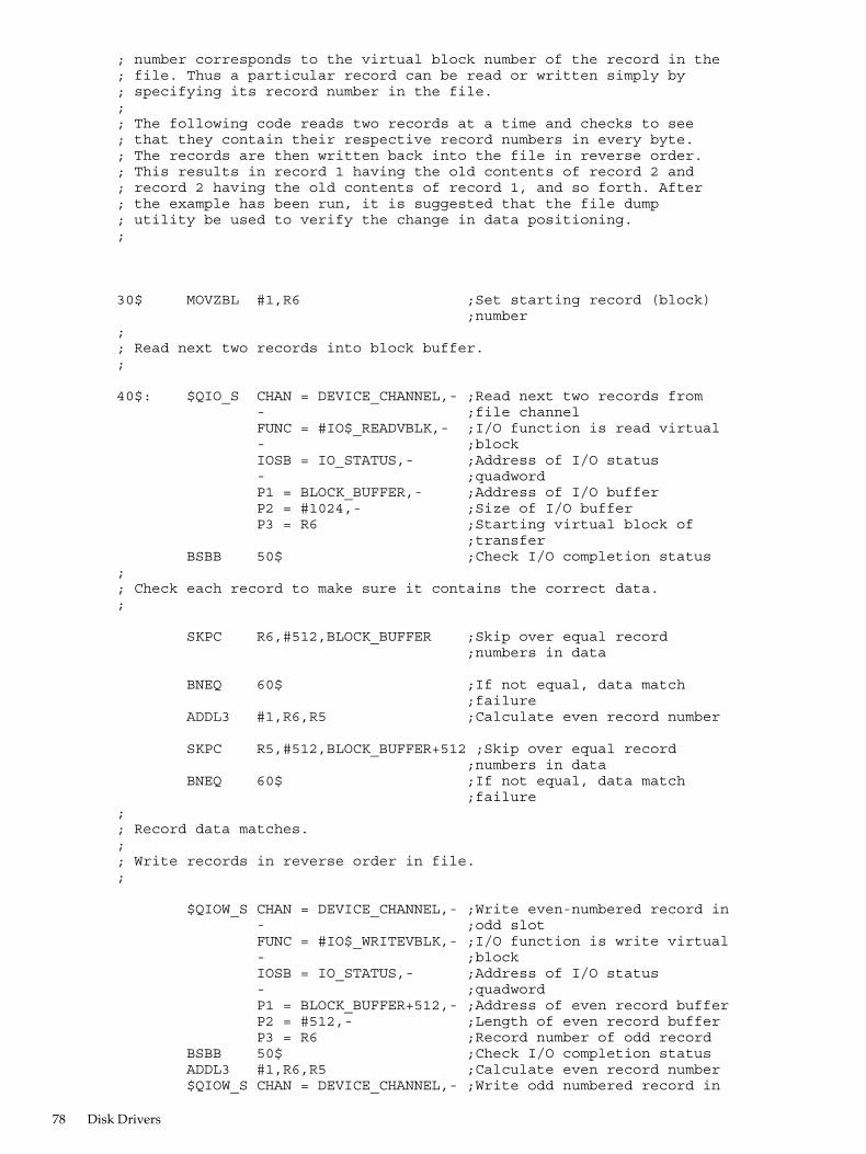
; number corresponds to the virtual block number of the record in the; file. Thus a particular record can be read or written simply by; specifying its record number in the file.;; The following code reads two records at a time and checks to see; that they contain their respective record numbers in every byte.; The records are then written back into the file in reverse order.; This results in record 1 having the old contents of record 2 and; record 2 having the old contents of record 1, and so forth. After; the example has been run, it is suggested that the file dump; utility be used to verify the change in data positioning.;
30$ MOVZBL #1,R6 ;Set starting record (block) ;number;; Read next two records into block buffer.;
40$: $QIO_S CHAN = DEVICE_CHANNEL,- ;Read next two records from - ;file channel FUNC = #IO$_READVBLK,- ;I/O function is read virtual - ;block IOSB = IO_STATUS,- ;Address of I/O status - ;quadword P1 = BLOCK_BUFFER,- ;Address of I/O buffer P2 = #1024,- ;Size of I/O buffer P3 = R6 ;Starting virtual block of ;transfer BSBB 50$ ;Check I/O completion status;; Check each record to make sure it contains the correct data.;
SKPC R6,#512,BLOCK_BUFFER ;Skip over equal record ;numbers in data
BNEQ 60$ ;If not equal, data match ;failure ADDL3 #1,R6,R5 ;Calculate even record number
SKPC R5,#512,BLOCK_BUFFER+512 ;Skip over equal record ;numbers in data BNEQ 60$ ;If not equal, data match ;failure;; Record data matches.;; Write records in reverse order in file.;
$QIOW_S CHAN = DEVICE_CHANNEL,- ;Write even-numbered record in - ;odd slot FUNC = #IO$_WRITEVBLK,- ;I/O function is write virtual - ;block IOSB = IO_STATUS,- ;Address of I/O status - ;quadword P1 = BLOCK_BUFFER+512,- ;Address of even record buffer P2 = #512,- ;Length of even record buffer P3 = R6 ;Record number of odd record BSBB 50$ ;Check I/O completion status ADDL3 #1,R6,R5 ;Calculate even record number $QIOW_S CHAN = DEVICE_CHANNEL,- ;Write odd numbered record in
78 Disk Drivers

- ;even slot FUNC = #IO$_WRITEVBLK,- ;I/O function is write virtual - ;block IOSB = IO_STATUS,- ;Address of I/O status - ;quadword P1 = BLOCK_BUFFER,- ;Address of odd record buffer P2 = #512,- ;Length of odd record buffer P3 = R5 ;Record number of even record BSBB 50$ ;Check I/O completion status ACBB #NUM_RECS-1,#2,R6,40$ ;Any more records to be read?
BRB 70$ ;
;; Check I/O completion status.;
50$: BLBC R0,70$ ;If low bit = 0, service ;failure MOVZWL IO_STATUS,R0 ;Get final I/O completion ;status BLBC R0,70$ ;If low bit = 0, I/O function RSB ;failure;; Record number mismatch in data.;
60$: MNEGL #4,R0 ;Set dummy error status value
;; All records have been read, verified, and odd/even pairs inverted;70$: PUSHL R0 ;Save final status $QIOW_S CHAN = DEVICE_CHANNEL,- ;Deaccess file FUNC = #IO$_DEACCESS ;I/O function is deaccess file $DASSGN_S CHAN = DEVICE_CHANNEL ;Deassign file device channel POPL R0 ;Retrieve final status RET ;
.END DISK_EXAMPLE
2.5 Disk Driver Programming Example 79

80
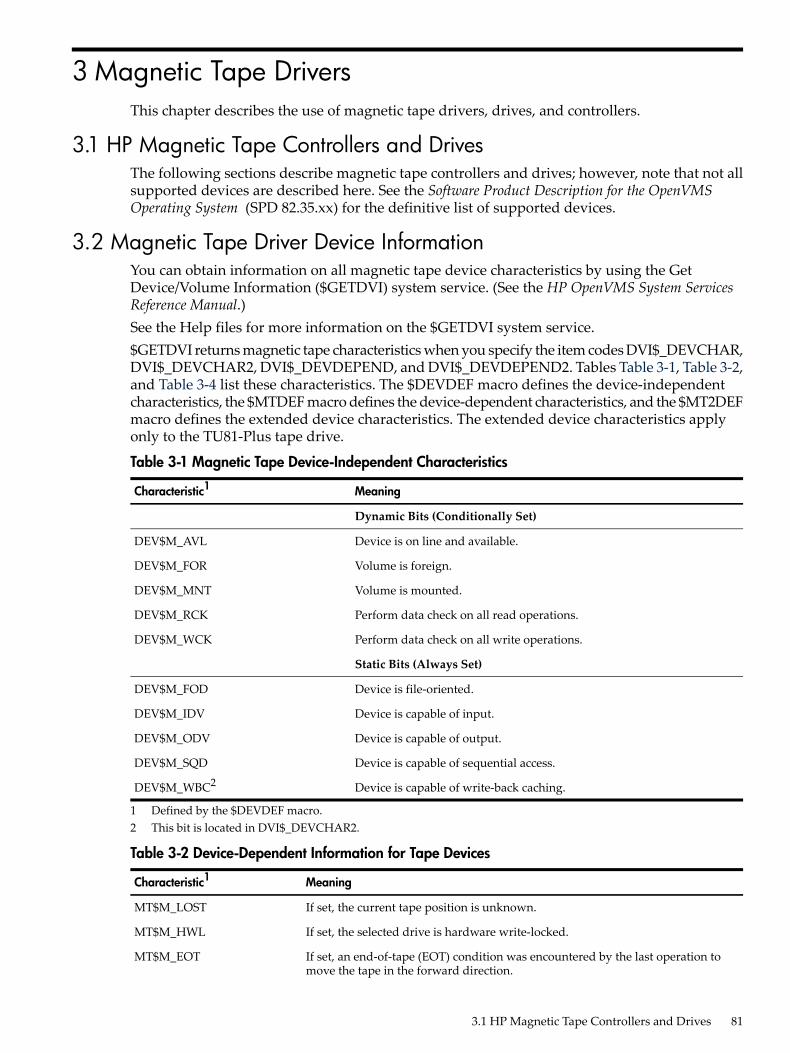
3 Magnetic Tape DriversThis chapter describes the use of magnetic tape drivers, drives, and controllers.
3.1 HP Magnetic Tape Controllers and DrivesThe following sections describe magnetic tape controllers and drives; however, note that not allsupported devices are described here. See the Software Product Description for the OpenVMSOperating System (SPD 82.35.xx) for the definitive list of supported devices.
3.2 Magnetic Tape Driver Device InformationYou can obtain information on all magnetic tape device characteristics by using the GetDevice/Volume Information ($GETDVI) system service. (See the HP OpenVMS System ServicesReference Manual.)See the Help files for more information on the $GETDVI system service.$GETDVI returns magnetic tape characteristics when you specify the item codes DVI$_DEVCHAR,DVI$_DEVCHAR2, DVI$_DEVDEPEND, and DVI$_DEVDEPEND2. Tables Table 3-1, Table 3-2,and Table 3-4 list these characteristics. The $DEVDEF macro defines the device-independentcharacteristics, the $MTDEF macro defines the device-dependent characteristics, and the $MT2DEFmacro defines the extended device characteristics. The extended device characteristics applyonly to the TU81-Plus tape drive.
Table 3-1 Magnetic Tape Device-Independent Characteristics
MeaningCharacteristic1
Dynamic Bits (Conditionally Set)
Device is on line and available.DEV$M_AVL
Volume is foreign.DEV$M_FOR
Volume is mounted.DEV$M_MNT
Perform data check on all read operations.DEV$M_RCK
Perform data check on all write operations.DEV$M_WCK
Static Bits (Always Set)
Device is file-oriented.DEV$M_FOD
Device is capable of input.DEV$M_IDV
Device is capable of output.DEV$M_ODV
Device is capable of sequential access.DEV$M_SQD
Device is capable of write-back caching.DEV$M_WBC2
1 Defined by the $DEVDEF macro.2 This bit is located in DVI$_DEVCHAR2.
Table 3-2 Device-Dependent Information for Tape Devices
MeaningCharacteristic1
If set, the current tape position is unknown.MT$M_LOST
If set, the selected drive is hardware write-locked.MT$M_HWL
If set, an end-of-tape (EOT) condition was encountered by the last operation tomove the tape in the forward direction.
MT$M_EOT
3.1 HP Magnetic Tape Controllers and Drives 81

Table 3-2 Device-Dependent Information for Tape Devices (continued)
MeaningCharacteristic1
If set, a tape mark was encountered by the last operation to move the tape.MT$M_EOF
If set, a beginning-of-tape (BOT) marker was encountered by the last operation tomove the tape in the reverse direction.
MT$M_BOT
If set, all data transfers are performed with even parity. If clear (normal case), alldata transfers are performed with odd parity. Only nonreturn-to-zero-invertedrecording at 800 bits/inch can have even parity.
MT$M_PARITY
Specifies the density at which all data transfer operations are performed. Possibledensity values are as follows:
MT$V_DENSITYMT$S_DENSITY
Group-coded recording, 6250 bits/inchMT$K_GCR_6250
Phase-encoded recording, 1600 bits/inchMT$K_PE_1600
Nonreturn-to-zero-inverted recording, 800 bits/inchMT$K_NRZI_800
Cartridge block mode recording2MT$K_BLK_833
Specifies the format in which all data transfers are performed. A possible formatvalue is as follows:
MT$V_FORMATMT$S_FORMAT
Normal PDP-11 format. Data bytes are recordedsequentially on tape with each byte occupying exactlyone frame.
MT$K_NORMAL11
If set, the most recent IO$_SKIPFILE function was performed using the optimizedSCSI space-by-file-marks algorithm. (See “Skip File” (page 88) for more informationabout the IO$M_ALLOWFAST modifier to the IO$_SKIPFILE function.)
MT$_FASTSKIP_USED
1 Defined by the $MTDEF macro.2 Only for the TK50 and TZ30 tape drives.
Table 3-3 Device-Dependent Information for Tape Devices
MeaningCharacteristic1
If set, write-back caching is enabled for this unit.MT2$V_WBC_ENABLE
If set, read caching is disabled for this unit.MT2$V_RDC_DISABLE
1 Defined by the $MT2DEF macro. Only for the TU81-Plus. Initial device status will show both of these bits cleared;write-back caching will be disabled, read caching will be enabled.
DVI$_DEVTYPE and DVI$_DEVCLASS return the device type and class names, which are definedby the $DCDEF macro. DVI$_DEVBUFSIZ returns the buffer size. The buffer size is the defaultto be used for tape transfers (normally 2048 bytes). The device class for magnetic tapes is$DCTAPE, and the device type is determined by the magnetic tape model. For example, thedevice type for the TA78 is DT$_TA78; for the TA81 it is DT$_TA81.This function code takes no function-dependent arguments.
3.3 Magnetic Tape Function CodesThe magnetic tape driver can perform logical, virtual, and physical I/O functions. Foreign-mounteddevices do not require privileges to perform logical and virtual I/O requests.Logical and physical I/O functions to magnetic tape devices allow sequential access to volumestorage and require only that the requesting process have direct access to the device. The resultsof logical and physical I/O operations are unpredictable if an ACP is present.Virtual I/O functions require intervention by an ACP and must be executed in a prescribed order.The normal order is to create and access a file, write information to that file, and deaccess thefile. Subsequently, when you access the file, you read the information and then deaccess the file.
82 Magnetic Tape Drivers

You can write over the file when the information it contains is no longer useful and the file hasexpired.Any number of bytes (from a minimum of 14 to a maximum of 65,535) can be read from or writteninto a single block by a single request. The number of bytes itself has no effect on the applicablequotas (direct I/O, buffered I/O, and AST). Reading or writing any number of bytes subtracts thesame amount from a quota.The volume to which a logical or virtual function is directed must be mounted for the functionactually to be executed. If it is not, either a “device not mounted” or “invalid volume” status isreturned in the I/O status block.Table 3-4 lists the logical, virtual, and physical magnetic tape I/O functions and their functioncodes. These functions are described in more detail in the following paragraphs. Chapter 1describes the QIO level interface to the magnetic tape device ACP. Chapter 10 describes featuresto improve performance for larger file transfers.
Table 3-4 Magnetic Tape I/O Functions
FunctionFunction ModifiersType1ArgumentsFunction Code
Search a tape for a specified fileand access the file if found andIO$M_ACCESS is set. If the fileis not found andIO$M_CREATE is set, create afile at end-of-tape (EOT)marker.
IO$M_CREATEIO$M_ACCESS
VP1,[P2],[P3],[P4],[P5]
IO$_ACCESS
Perform miscellaneous controlfunctions. 2
IO$M_DMOUNTVP1,[P2],[P3], [P4],[P5]
IO$_ACPCONTROL
Clear volume valid bit.PIO$_AVAILABLE
Create a file.IO$M_CREATEIO$M_ACCESS
VP1,[P2][,[P3],[P4],[P5]
IO$_CREATE
Deaccess a file and, if the filehas been written, write outtrailer records.
VP1,[P2],[P3],[P4],[P5]
IO$_DEACCESS
Erase a prescribed section of thetape.
IO$M_NOWAITPIO$_DSE3
Flush the controller cache totape.
LIO$_FLUSH
Write user labels.VP1,[P2],[P3],[P4],[P5]
IO$_MODIFY
Initialize volume valid bit.PIO$_PACKACK
Read logical block.IO$M_DATACHECK5
IO$M_INHRETRYIO$M_REVERSE6
LP1,P2IO$_READLBLK 4
Read physical block.IO$M_DATACHECK5
IO$M_INHRETRYIO$M_REVERSE6
PP1,P2IO$_READPBLK
Read virtual block.IO$M_DATACHECK5
IO$M_INHRETRYIO$M_REVERSE6
VP1,P2IO$_READVBLK
Reposition tape to thebeginning-of-tape (BOT)marker.
IO$M_INHRETRYIO$M_NOWAITIO$M_RETENSION
LIO$_REWIND
3.3 Magnetic Tape Function Codes 83
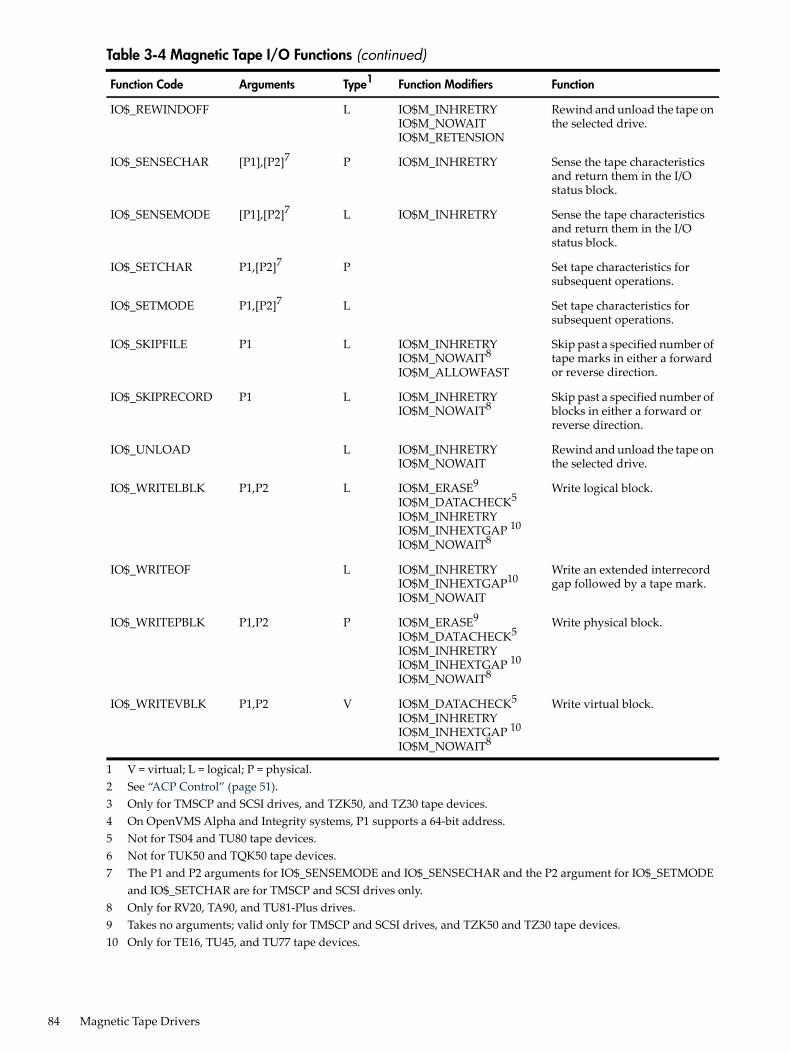
Table 3-4 Magnetic Tape I/O Functions (continued)
FunctionFunction ModifiersType1ArgumentsFunction Code
Rewind and unload the tape onthe selected drive.
IO$M_INHRETRYIO$M_NOWAITIO$M_RETENSION
LIO$_REWINDOFF
Sense the tape characteristicsand return them in the I/Ostatus block.
IO$M_INHRETRYP[P1],[P2]7IO$_SENSECHAR
Sense the tape characteristicsand return them in the I/Ostatus block.
IO$M_INHRETRYL[P1],[P2]7IO$_SENSEMODE
Set tape characteristics forsubsequent operations.
PP1,[P2]7IO$_SETCHAR
Set tape characteristics forsubsequent operations.
LP1,[P2]7IO$_SETMODE
Skip past a specified number oftape marks in either a forwardor reverse direction.
IO$M_INHRETRYIO$M_NOWAIT8
IO$M_ALLOWFAST
LP1IO$_SKIPFILE
Skip past a specified number ofblocks in either a forward orreverse direction.
IO$M_INHRETRYIO$M_NOWAIT8
LP1IO$_SKIPRECORD
Rewind and unload the tape onthe selected drive.
IO$M_INHRETRYIO$M_NOWAIT
LIO$_UNLOAD
Write logical block.IO$M_ERASE9
IO$M_DATACHECK5
IO$M_INHRETRYIO$M_INHEXTGAP 10
IO$M_NOWAIT8
LP1,P2IO$_WRITELBLK
Write an extended interrecordgap followed by a tape mark.
IO$M_INHRETRYIO$M_INHEXTGAP10
IO$M_NOWAIT
LIO$_WRITEOF
Write physical block.IO$M_ERASE9
IO$M_DATACHECK5
IO$M_INHRETRYIO$M_INHEXTGAP 10
IO$M_NOWAIT8
PP1,P2IO$_WRITEPBLK
Write virtual block.IO$M_DATACHECK5
IO$M_INHRETRYIO$M_INHEXTGAP 10
IO$M_NOWAIT8
VP1,P2IO$_WRITEVBLK
1 V = virtual; L = logical; P = physical.2 See “ACP Control” (page 51).3 Only for TMSCP and SCSI drives, and TZK50, and TZ30 tape devices.4 On OpenVMS Alpha and Integrity systems, P1 supports a 64-bit address.5 Not for TS04 and TU80 tape devices.6 Not for TUK50 and TQK50 tape devices.7 The P1 and P2 arguments for IO$_SENSEMODE and IO$_SENSECHAR and the P2 argument for IO$_SETMODE
and IO$_SETCHAR are for TMSCP and SCSI drives only.8 Only for RV20, TA90, and TU81-Plus drives.9 Takes no arguments; valid only for TMSCP and SCSI drives, and TZK50 and TZ30 tape devices.10 Only for TE16, TU45, and TU77 tape devices.
84 Magnetic Tape Drivers

The function-dependent arguments for IO$_CREATE, IO$_ACCESS, IO$_DEACCESS,IO$_MODIFY, IO$_ACPCONTROL are as follows:• P1—The address of the file information block (FIB) descriptor.• P2—Optional. The address of the file name string descriptor. If specified with IO$_ACCESS,
the name identifies the file being sought. If specified with IO$_CREATE, the name is thename of the created file.
• P3—Optional. The address of the word that is to receive the length of the resultant file namestring.
• P4—Optional. The address of a descriptor for a buffer that is to receive the resultant filename string.
• P5—Optional. The address of a list of attribute descriptors. If specified with IO$_ACCESS,the attributes of the file are returned to the user. If specified with IO$_CREATE, P5 is theaddress of the attribute descriptor list for the new file. All file attributes for IO$_MODIFYare ignored.
See Chapter 1 for more information on these functions.The function-dependent arguments for IO$_READVBLK, IO$_READLBLK, IO$_READPBLK,IO$_WRITEVBLK, IO$_WRITELBLK, and IO$_WRITEPBLK are as follows:• P1—The starting virtual address of the buffer that is to receive the data in the case of a read
operation; or, in the case of a write operation, the virtual address of the buffer that is to bewritten on the tape. On OpenVMS Alpha, P1 can be a 64-bit address.
• P2—The length of the buffer specified by P1.The function-dependent argument for IO$_SKIPFILE and IO$_SKIPRECORD is:• P1—The number of tape marks to skip over in the case of a skip file operation; or, in the
case of a skip record operation, the number of blocks to skip over. If a positive number isspecified, the tape moves forward; if a negative number is specified, the tape moves inreverse. (The maximum number of tape marks or records that P1 can specify is 32,767.)
Example 3-1 shows the correct method of defining the P1 parameter in an IO$_SKIPRECORDQIO.
3.3 Magnetic Tape Function Codes 85

Example 3-1 Defining the P1 Parameter in a IO$_SKIPRECORD QIO
.
.
.
TAPE_CHAN: .WORD 0IOSB: .WORD 0 .WORD 0 .LONG 0DEVICE: .ASCID /$127$MUA0:/RECORD: .LONG 2000; .PSECT CODE,EXE,NOWRT; .ENTRY MT_IO,^M
; $ASSIGN_S CHAN=TAPE_CHAN,- DEVNAM=DEVICE BLBC R0,EXIT_ERROR; $QIOW_S CHAN=TAPE_CHAN,- FUNC=#IO$_SKIPRECORD,- IOSB=IOSB,- P1=RECORD BLBC R0,EXIT_ERROR $EXIT_S R0
.
.
.
EXIT_ERROR: $EXIT_S R0 .END MT_IO
3.3.1 ReadThe read function reads data into a specified buffer in the forward or reverse direction startingat the next block position.The operating system provides the following read function codes:• IO$_READVBLK—Read virtual block• IO$_READLBLK—Read logical block• IO$_READPBLK—Read physical blockIf a read virtual block function is directed to a volume that is mounted foreign, it is convertedto a read logical block function. If a read virtual block function is directed to a volume that ismounted structured, the volume is handled the same way as a file-structured device.Two function-dependent arguments are used with these codes: P1 and P2. These arguments aredescribed in “Magnetic Tape Function Codes” (page 82).If the read function code includes the reverse function modifier (IO$M_REVERSE), the drivereads the tape in the reverse direction instead of the forward direction. IO$M_REVERSE cannotbe specified for the TUK50 and TQK50 devices.The data check function modifier (IO$M_DATACHECK) can be used with all read functions. Ifthis modifier is specified, a data check operation is performed after the read operation completes.(The drive performs a space reverse or space forward between the read and data check operations.)A data check operation is also performed if the volume that was read, or the volume on which
86 Magnetic Tape Drivers

the file resides (virtual read), has the characteristic “data check all reads.” Furthermore, a datacheck is performed after a virtual read if the file has the attribute “data check on read.” The TS04and TU80 tape drives do not support the data check function.For read physical block and read logical block functions, the drive returns the statusSS$_NORMAL (not end-of-tape status) if either of the following conditions occurs and no othererror condition exists:• The tape is positioned past the end-of-tape (EOT) position at the start of the read (forward
or reverse) operation.• The tape enters the EOT region as a result of the read (forward) operation.The transferred byte count reflects the actual number of bytes read.If the drive reads a tape mark during a logical or physical read operation in either the forwardor reverse direction, any of the following conditions can return an end-of-file (EOF) status:• The tape is positioned past the EOT position at the start of the read operation.• The tape enters the EOT region as a result of the read operation.• The drive reads a tape mark as a result of a read operation but the tape does not enter the
EOT region.An EOF status is also returned if the drive attempts a read operation in the reverse directionwhen the tape is positioned at the beginning-of-tape (BOT) marker. All conditions that cause anEOF status result in a transferred byte count of zero.If the drive attempts to read a block that is larger than the specified memory buffer during alogical or physical read operation, a data overrun status is returned. The buffer receives only thefirst part of the block. On a read in the reverse direction (on drives other than the TK50 and TZ30)the buffer receives only the latter part of the block. The transferred byte count is equal to theactual size of the block. Read reverse starts at the top of the buffer. Therefore, the start of theblock is at P1 plus P2 minus the length read. The TUK50 and TZ30 cannot actually perform readreverse operations; they must be simulated by the driver. Therefore, the data returned are thosethat would have been returned had the block been read in the forward direction.It is not possible to read a block that is less than 14 bytes in length. Records that contain less than14 bytes are termed “noise blocks” and are completely ignored by the driver.
3.3.2 WriteThe write function writes data from a specified buffer to tape in the forward direction startingat the next block position.The operating system provides the following write function codes:• IO$_WRITEVBLK—Write virtual block• IO$_WRITELBLK—Write logical block• IO$_WRITEPBLK—Write physical blockIf a write virtual block function is directed to a volume that is mounted foreign, the function isconverted to a write logical block. If a write virtual block function is directed to a volume thatis mounted structured, the volume is handled the same way as a file-structured device.Two function-dependent arguments are used with these codes: P1 and P2. These arguments aredescribed in “Magnetic Tape Function Codes” (page 82).The IO$M_ERASE function modifier can be used with the IO$_WRITELBLK and IO$_WRITEPBLKfunction codes to erase a user-selected part of a tape. This modifier propagates an erase patternof all zeros from the current tape position to 10 feet past the EOT position and then rewinds tothe BOT marker.The data check function modifier (IO$M_DATACHECK) can be used with all write functions.If this modifier is specified, a data check operation is performed after the write operationcompletes. (The drive performs a space reverse between the write and the data check operations.)
3.3 Magnetic Tape Function Codes 87

The driver forces a data check operation when an error occurs during a write operation. Thisensures that the data can be reread. A data check operation is also performed if the volumewritten, or the volume on which the file resides (virtual write), has the characteristic “data checkall writes.” Furthermore, a data check is performed after a virtual write if the file has the attribute“data check on write.” The TS04 and TU80 tape drives do not support the data check function.If the IO$M_NOWAIT function modifier is specified, write-back caching is enabled on aper-command basis. IO$M_NOWAIT is applicable only to TU81-Plus drives.If the drive performs a write physical block or a write logical block operation, an EOT status isreturned if either of the following conditions occurs and no other error condition exists:• The tape is positioned past the EOT position at the start of the write operation.• The tape enters the EOT region as a result of the write operation.The transferred byte count reflects the size of the block written. It is not possible to write a blockless than 14 bytes in length. An attempt to do so results in the return of a bad parameter statusfor the QIO request.
3.3.3 RewindThe rewind function repositions the tape to the beginning-of-tape (BOT) marker.If the IO$M_NOWAIT function modifier is specified, the I/O operation is completed when therewind is initiated. Otherwise, I/O completion does not occur until the tape is positioned at theBOT marker.If the IO$M_RETENSION function modifier is specified and the device supports the retentionoperation, the rewind function positions the tape to the physical-end-of-tape (EOT) marker andrewinds the tape to the BOT marker. If the tape does not support the IO$M_RETENSION modifier,a SS$_ILLIOFUNC error is returned.IO$_REWIND has no function-dependent arguments.
3.3.4 Skip FileThe skip file function (IO$_SKIPFILE) skips past a specified number of tape marks in either aforward or reverse direction. A function-dependent argument (P1) is provided to specify thenumber of tape marks to be skipped, as shown in Figure 3-1. If a positive file count is specified,the tape moves forward; if a negative file count is specified, the tape moves in reverse. (The actualnumber of files skipped is returned as an unsigned number in the I/O status block.)
Figure 3-1 IO$_SKIPFILE Argument
Not Used File Count
31
P1:
1516 0
Only tape marks (when the tape moves in either direction) and the BOT marker (when the tapemoves in reverse) are counted during a skip file operation. The BOT marker terminates a skipfile function in the reverse direction. The end-of-tape (EOT) marker does not terminate a skipfile function in either the forward or reverse direction. A negative skip file function leaves thetape positioned just before a tape mark (at the end of a file) unless the BOT marker is encountered,whereas a positive skip file function leaves the tape positioned just past the tape mark.A skip file function in the forward direction can also be terminated if two consecutive tape marksare encountered. “Logical End-of-Volume (EOV) Detection” (page 89) describes this feature.The IO$M_ALLOWFAST modifier can be used with the IO$_SKIPFILE function to provide betterperformance on SCSI tape drives that support the SCSI space-by-file-marks command and theSCSI read position command.
88 Magnetic Tape Drivers

When the IO$M_ALLOWFAST modifier is specified, a tape operation skips over consecutivetape marks that are not immediately before the end-of-data position on the medium. However,if two consecutive tape marks are detected immediately before the end-of-data position on thetape, the tape is positioned between these two tape marks and the SS$_ENDOFVOLUME statusis returned.The IO$M_ALLOWFAST modifier allows a SCSI tape subsystem to use the optimizedIO$_SKIPFILE if it is capable. If a specific tape device does not adequately support the optimizedIO$_SKIPFILE that uses the SCSI space-by-file-marks command, the tape subsystem uses thestandard space-by-records algorithm.
3.3.5 Skip RecordThe skip record function skips past a specified number of physical tape blocks in either a forwardor reverse direction. A device- or function-dependent argument (P1) specifies the number ofblocks to skip, as shown in Figure 3-2. If a positive block count is specified, the tape movesforward; if a negative block count is specified, the tape moves in reverse. The actual number ofblocks skipped is returned as an unsigned number in the I/O status block. If a tape mark isdetected, the count is the number of blocks skipped, plus 1 (forward tape motion) or minus 1(reverse tape motion).
Figure 3-2 IO$_SKIPRECORD Argument
Not Used Block Count
31
P1:
1516 0
A skip record operation is terminated by the end-of-file (EOF) marker when the tape moves ineither direction, by the BOT marker when the tape moves in reverse, and by the EOT markerwhen the tape moves forward.A skip record function in the forward direction can also be terminated if the tape was originallypositioned between two tape marks. “Logical End-of-Volume (EOV) Detection” (page 89)describes this feature.
3.3.5.1 Logical End-of-Volume (EOV) DetectionA skip file or skip record operation that uses the standard space-by-records algorithm is terminatedwhen two consecutive tape marks are encountered when the tape moves in the forward direction.After the operation terminates, the tape remains positioned between the two tape marks thatwere detected. The I/O status block (IOSB) returns the status SS$_ENDOFVOLUME and theactual number of files (or records) skipped during the operation prior to the detection of thesecond tape mark. The skip count is returned in the high-order word of the first longword of theIOSB.An optimized skip file that uses the IO$M_ALLOWFAST modifier is terminated when theend-of-data position is encountered. If two consecutive tape marks immediately precede theend-of-data position on the tape, the tape is positioned between these two tape marks. TheSS$_ENDOFVOLUME status and the skip count are returned in the IOSB.Subsequent skip record (or skip file) requests terminate immediately when the tape is positionedbetween the two tape marks, producing no net tape movement and returning theSS$_ENDOFVOLUME status with a skip count of zero.To move the tape beyond the second tape mark, you must employ another I/O function. Forexample, the IO$_READLBLK function, if issued after receipt of the SS$_ENDOFVOLUME statusreturn, terminates with an SS$_ENDOFFILE status and with the tape positioned just past thesecond tape mark. From this new position, other skip functions could be issued to produceforward tape motion (assuming there is additional data on the tape).
3.3 Magnetic Tape Function Codes 89

If three consecutive tape marks are encountered during a skip file function, you must issue twoIO$_READLBLK functions, the first to get the SS$_ENDOFFILE return and the second to positionthe tape past the third tape mark.
3.3.6 Write End-of-FileThe write end-of-file (EOF) function writes an extended interrecord gap (of approximately 3inches for nonreturn-to-zero-inverted (NRZI) recording and 1.5 inches for phase-encoded (PE)recording) followed by a tape mark. No device- or function-dependent arguments are used withIO$_WRITEOF.An end-of-tape (EOT) status is returned in the I/O status block if either of the following conditionsis present and no other error conditions occur:• A write EOF function is executed while the tape is positioned past the EOT marker.• A write EOF function causes the tape position to enter the EOT region.
3.3.7 Rewind OfflineThe rewind offline function rewinds and unloads the tape on the selected drive.The I/O operation is completed as soon as the tape movement is initiated. The actual finish ofthe mechanical rewind or unload operation may occur long after the I/O operation completes.If the IO$M_RETENSION function modifier is specified and the device supports the retentionoperation, the rewind offline function positions the tape to the physical end-of-tape (EOT) markerand rewinds the tape to the beginning-of-tape (BOT) marker. If the tape does not support theIO$M_RETENSION modifier, a SS$_ILLIOFUNC error is returned.No device- or function-dependent arguments are used with IO$_REWINDOFF.
3.3.8 UnloadThe unload function rewinds and unloads the tape on the selected drive. The unload functionis functionally the same as the rewind offline function. If the IO$M_NOWAIT function modifieris specified, the I/O operation is completed as soon as the rewind operation is initiated. No device-or function-dependent arguments are used with IO$_UNLOAD.
3.3.9 Sense Tape ModeThe sense tape mode function senses the current device-dependent and extended devicecharacteristics (see Tables Table 3-2 and Table 3-4).The operating system provides the following function codes:• IO$_SENSEMODE—Sense mode• IO$_SENSECHAR—Sense characteristicsSense mode requires logical I/O privilege. Sense characteristics requires physical I/O privilege.For TMSCP and SCSI drives, the sense mode function returns magnetic tape information in auser-supplied buffer, which is specified by the following function-dependent arguments:• P1—Optional. Address of a user-supplied buffer.• P2—Optional. Length of a user-supplied buffer.If P1 is not zero, the sense mode buffer returns the tape characteristics. (If P2=8, the secondlongword of the buffer contains the device-dependent characteristics. If P2=12, the secondlongword contains the device-dependent characteristics and the third longword contains thetape densities that the drive supports and the extended tape characteristics.) The extendedcharacteristics are identical to the information returned by DVI$_DEVDEPEND2 (see Table 3-4).Figure 3-3 shows the contents of the P1 buffer.
90 Magnetic Tape Drivers

Figure 3-3 Sense Mode P1 Buffer
Buffer Size
Tape Characteristics*
*From UCB$L_DEVDEPEND
*From UCB$L_DEVDEPEND**From UCB$L_DEVDEPEND2
Type Class
31P2=8:
16 15 0
Buffer Size
Extended Tape Characteristics**
Tape Characteristics*
Supported Densities**
31P2=12:
16 15
8 7
Type Class
8 7 0
3.3.10 Set ModeSet mode operations affect the operation and characteristics of the associated magnetic tapedevice. The operating system defines two types of set mode functions: set mode and setcharacteristics.Set mode requires logical I/O privilege. Set characteristics requires physical I/O privilege. Thefollowing function codes are provided:• IO$_SETMODE—Set mode• IO$_SETCHAR—Set characteristicsThese functions take the following device- or function-dependent arguments (other argumentsare ignored):• P1—The address of a characteristics buffer.• P2—Optional. The length of the characteristics buffer. The default is 8 bytes. If a length of
12 bytes is specified, the third longword (which is for TMSCP and SCSI drives only) specifiesthe extended tape characteristics.
Figure 3-4 shows the P1 characteristics buffer for IO$_SETMODE. Figure 3-5 shows the samebuffer for IO$_SETCHAR.
3.3 Magnetic Tape Function Codes 91
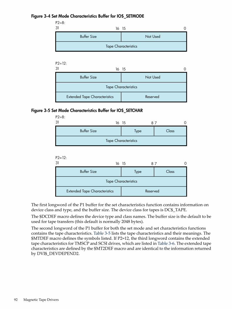
Figure 3-4 Set Mode Characteristics Buffer for IO$_SETMODE
Buffer Size
Tape Characteristics
Not Used
31P2=8:
16 15 0
Buffer Size
Extended Tape Characteristics
Tape Characteristics
Not Used
Reserved
31P2=12:
16 15 0
Figure 3-5 Set Mode Characteristics Buffer for IO$_SETCHAR
Buffer Size
Tape Characteristics
Type Class
31P2=8:
16 15 0
Buffer Size
Extended Tape Characteristics
Tape Characteristics
Reserved
31P2=12:
16 15
8 7
Type Class
8 7 0
The first longword of the P1 buffer for the set characteristics function contains information ondevice class and type, and the buffer size. The device class for tapes is DC$_TAPE.The $DCDEF macro defines the device type and class names. The buffer size is the default to beused for tape transfers (this default is normally 2048 bytes).The second longword of the P1 buffer for both the set mode and set characteristics functionscontains the tape characteristics. Table 3-5 lists the tape characteristics and their meanings. The$MTDEF macro defines the symbols listed. If P2=12, the third longword contains the extendedtape characteristics for TMSCP and SCSI drives, which are listed in Table 3-6. The extended tapecharacteristics are defined by the $MT2DEF macro and are identical to the information returnedby DVI$_DEVDEPEND2.
92 Magnetic Tape Drivers
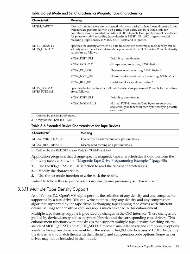
Table 3-5 Set Mode and Set Characteristics Magnetic Tape Characteristics
MeaningCharacteristic1
If set, all data transfers are performed with even parity. If clear (normal case), all datatransfers are performed with odd parity. Even parity can be selected only fornonreturn-to-zero-inverted recording at 800 bits/inch. Even parity cannot be selectedfor phase-encoded recording (tape density is MT$K_PE_1600) or group-codedrecording (tape density is MT$K_GCR_6250) and is ignored.
MT$M_PARITY
Specifies the density at which all data transfers are performed. Tape density can beset only when the selected drive's tape position is at the BOT marker. Possible densityvalues are as follows:
MT$V_DENSITYMT$S_DENSITY
Default system density.MT$K_DEFAULT
Group-coded recording, 6250 bits/inch.MT$K_GCR_6250
Phase-encoded recording, 1600 bits/inch.MT$K_PE_1600
Nonreturn-to-zero-inverted recording, 800 bits/inch.MT$K_NRZI_800
Cartridge block mode recording.2MT$K_BLK_833
Specifies the format in which all data transfers are performed. Possible format valuesare as follows:
MT$V_FORMATMT$S_FORMAT
Default system format.MT$K_DEFAULT
Normal PDP-11 format. Data bytes are recordedsequentially on tape with each byte occupying exactlyone frame.
MT$K_NORMAL11
1 Defined by the $MTDEF macro.2 Only for the TK50 and TZ30.
Table 3-6 Extended Device Characteristics for Tape Devices
MeaningCharacteristic1
Enable write-back caching on a per-unit basis.MT2$V_WBC_ENABLE
Disable read caching on a per-unit basis.MT2$V_RDC_DISABLE
1 Defined by the $MT2DEF macro. Only for TU81-Plus drives.
Application programs that change specific magnetic tape characteristics should perform thefollowing steps, as shown in “Magnetic Tape Drive Programming Examples” (page 95):1. Use the IO$_SENSEMODE function to read the current characteristics.2. Modify the characteristics.3. Use the set mode function to write back the results.Failure to follow this sequence results in clearing any previously set characteristic.
3.3.11 Multiple Tape Density SupportAs of Version 7.2, OpenVMS Alpha permits the selection of any density and any compressionsupported by a tape drive. You can write to tapes using any density and any compressionalgorithm supported by the tape drive. Exchanging tapes among tape drives with differentdefault settings for density or compression is much easier with this enhancement.Multiple tape density support is provided by changes in the QIO interface. These changes areguided by device/density tables in system libraries and the corresponding class drivers. Thisenhancement functions with tape drives that support multiple tape density switching via thestandard MODE_SENSE and MODE_SELECT mechanisms. All density and compression optionsavailable for a given drive is accessible by the system. The QIO interface uses MT3DEF to identifythe drives, and to match them with their density and compression code options. Some newerdrives may not be included in the module.
3.3 Magnetic Tape Function Codes 93

NOTE: After the media has been initialized to a specific density, it retains that density untilthe media is initialized to a different density. For example, if an HP media has been initializedwith TK86 density, the DCL command MOUNT/DENSITY=TK85 will have no effect because themedia is initialized at TK86 density. Likewise, BACKUP/DENSITY=TK85 will have no effect ifthe media is initialized at TK86 density. However, BACKUP/DENS=TK85/INITIALIZE initializesthe media to TK85 density.
These enhancements allow IO$_SETMODE and IO$_SENSEMODE to function with most densityvalues and a wider variety of drives. The system management utilities BACKUP and MOUNTtake advantage of this added functionality. For more information about multiple tape densitysupport with these utilities, see the HP OpenVMS System Management Utilities Reference Manual.For more information about enhancements in INITIALIZE, see theHPOpenVMSDCLDictionary.
3.3.12 Data Security EraseThe data security erase function erases all data from the current position of the volume to 10 feetbeyond the EOT reflective strip, and then rewinds the tape to the BOT marker. It is a physicalI/O function and requires the access privilege necessary to perform physical I/O functions. Thefollowing function code is provided:• IO$_DSEIf the function is issued when a tape is positioned at the BOT marker, all data on the tape iserased.IO$_DSE takes no device- or function-dependent arguments.
3.3.13 ModifySpecifying the ATR$C_USERLABEL or ATR$C_ENDLBLAST attributes with IO$_MODIFYresults in a bad attribute error. If any other attributes are specified, the IO$_MODIFY functionis treated as a no-operation; that is, the function returns success, but no action is performed.
3.3.14 Pack AcknowledgeThe pack acknowledge function sets the volume valid bit for all magnetic tape devices. It is aphysical I/O function and requires the access privilege to perform physical I/O. The followingfunction code is provided:• IO$_PACKACKIO$_PACKACK must be the first function issued when a volume is placed in a magnetic tapedrive. IO$_PACKACK is issued automatically when the DCL commands INITIALIZE or MOUNTare issued.
3.3.15 AvailableThe available function clears the volume valid bit for all magnetic tape drives, that is, it reversesthe function performed by the pack acknowledge function (see the “Pack Acknowledge”(page 94)). A rewind of the tape is performed (applicable to all tape drives). No unload functionis issued to the drive. The following function code is provided:• IO$_AVAILABLEThis function takes no function-dependent arguments.
94 Magnetic Tape Drivers
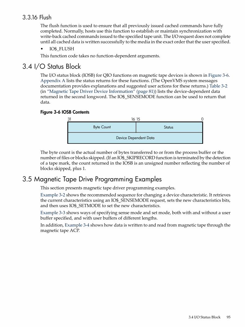
3.3.16 FlushThe flush function is used to ensure that all previously issued cached commands have fullycompleted. Normally, hosts use this function to establish or maintain synchronization withwrite-back cached commands issued to the specified tape unit. The I/O request does not completeuntil all cached data is written successfully to the media in the exact order that the user specified.• IO$_FLUSHThis function code takes no function-dependent arguments.
3.4 I/O Status BlockThe I/O status block (IOSB) for QIO functions on magnetic tape devices is shown in Figure 3-6.Appendix A lists the status returns for these functions. (The OpenVMS system messagesdocumentation provides explanations and suggested user actions for these returns.) Table 3-2(in “Magnetic Tape Driver Device Information” (page 81)) lists the device-dependent datareturned in the second longword. The IO$_SENSEMODE function can be used to return thatdata.
Figure 3-6 IOSB Contents
Device Dependent Data
Byte Count Status
31 1516 0
The byte count is the actual number of bytes transferred to or from the process buffer or thenumber of files or blocks skipped. (If an IO$_SKIPRECORD function is terminated by the detectionof a tape mark, the count returned in the IOSB is an unsigned number reflecting the number ofblocks skipped, plus 1.
3.5 Magnetic Tape Drive Programming ExamplesThis section presents magnetic tape driver programming examples.Example 3-2 shows the recommended sequence for changing a device characteristic. It retrievesthe current characteristics using an IO$_SENSEMODE request, sets the new characteristics bits,and then uses IO$_SETMODE to set the new characteristics.Example 3-3 shows ways of specifying sense mode and set mode, both with and without a userbuffer specified, and with user buffers of different lengths.In addition, Example 3-4 shows how data is written to and read from magnetic tape through themagnetic tape ACP.
3.4 I/O Status Block 95

Example 3-2 Device Characteristic Program Example
$QIOW_S - ; Get current characteristics. FUNC = #IO$_SENSEMODE,- ; - Sense mode CHAN = CHANNEL,- ; - Channel IOSB = IO_STATUS,- ; - IOSB P1 = BUFFER,- ; - User buffer supplied P2 = #12 ; - Buffer length = 12 . . .(Check for errors) . . .(Set desired characteristics bits) . . .
$QIOW_S - ; Set new characteristics. FUNC = #IO$_SETMODE,- ; - Set Mode CHAN = CHANNEL,- ; - Channel IOSB = IO_STATUS,- ; - IOSB P1 = BUFFER,- ; - User buffer address P2 = #12 ; - Buffer length = 12 . . .(Check for errors) . . .
96 Magnetic Tape Drivers

Example 3-3 Set Mode and Sense Mode Program Example
.PSECT IMPURE, NOEXE, NOSHR
$IODEF
DEVICE_NAME: ; Name of device .ASCID /MUA0/ ;
CHANNEL: ; Channel to device .WORD 0 ;
BUFFER: .BLKL 3 ; Set/Sense characteristics ; buffer
IO_STATUS: ; Final I/O status .QUAD 0 ;
.PSECT CODE, RD, NOWRT, EXE
.ENTRY MAIN,^M
$ASSIGN_S - ; Assign a channel to device DEVNAM = DEVICE_NAME,- ; CHAN = CHANNEL ;
BSBW ERR_CHECK2 ; Check for errors
$QIOW_S - ; Get current characteristics FUNC = #IO$_SENSEMODE,-; No user buffer supplied CHAN = CHANNEL,- ; IOSB = IO_STATUS ;
BSBW ERR_CHECK ; Check for errors
$QIOW_S - ; Get current characteristics FUNC = #IO$_SENSEMODE,-; User buffer supplied, length CHAN = CHANNEL,- ; defaulted IOSB = IO_STATUS,- ; P1 = BUFFER ;
BSBW ERR_CHECK ; Check for errors
$QIOW_S - ; Get current characteristics FUNC = #IO$_SENSEMODE,-; User buffer supplied, length CHAN = CHANNEL,- ; = 8 IOSB = IO_STATUS,- ; P1 = BUFFER,- ; P2 = #8 ;
BSBW ERR_CHECK ; Check for errors
$QIOW_S - ; Get extended characteristics FUNC = #IO$_SENSEMODE,-; User buffer supplied, length CHAN = CHANNEL,- ; = 12 IOSB = IO_STATUS,- ; P1 = BUFFER,- ; P2 = #12 ;
BSBW ERR_CHECK ; Check for errors
3.5 Magnetic Tape Drive Programming Examples 97

$QIOW_S
FUNC = #IO$_SETMODE,- ; Length defaulted CHAN = CHANNEL,- ; IOSB = IO_STATUS,- ; P1 = BUFFER ;
BSBW ERR_CHECK ; Check for errors
$QIOW_S - ; Set new characteristics FUNC = #IO$_SETMODE,- ; Length = 8 CHAN = CHANNEL,- ; IOSB = IO_STATUS,- ; P1 = BUFFER,- ; P2 = #8 ;
BSBW ERR_CHECK ; Check for errors
$QIOW_S - ; Set extended characteristics FUNC = #IO$_SETMODE,- ; Length = 12 CHAN = CHANNEL,- ; IOSB = IO_STATUS,- ; P1 = BUFFER,- ; P2 = #12 ;
BSBW ERR_CHECK ; Check for errors
RET
.ENABLE LSB
ERR_CHECK: BLBS IO_STATUS,ERR_CHECK2 ; Continue if good IOSB MOVZWL IO_STATUS,-(SP) ; Otherwise, set up for stop BRB 10$ ; Branch to common code
ERR_CHECK2: BLBS R0,20$ ; Continue if good status PUSHL R0 ; Otherwise, set up for stop10$: CALLS #1,G^LIB$STOP ; Stop execution
20$: RSB
.DISABLE LSB
.END MAIN
98 Magnetic Tape Drivers
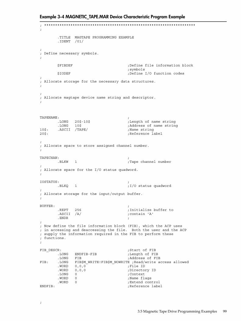
Example 3-4 MAGNETIC_TAPE.MAR Device Characteristic Program Example
; *********************************************************************;
.TITLE MAGTAPE PROGRAMMING EXAMPLE .IDENT /01/
;; Define necessary symbols.;
$FIBDEF ;Define file information block ;symbols $IODEF ;Define I/O function codes;; Allocate storage for the necessary data structures.;
;; Allocate magtape device name string and descriptor.;
TAPENAME: ; .LONG 20$-10$ ;Length of name string .LONG 10$ ;Address of name string10$: .ASCII /TAPE/ ;Name string20$: ;Reference label
;; Allocate space to store assigned channel number.;
TAPECHAN: ; .BLKW 1 ;Tape channel number;; Allocate space for the I/O status quadword.;
IOSTATUS: ; .BLKQ 1 ;I/O status quadword;; Allocate storage for the input/output buffer.;
BUFFER: ; .REPT 256 ;Initialize buffer to .ASCII /A/ ;contain 'A' .ENDR ;;; Now define the file information block (FIB), which the ACP uses; in accessing and deaccessing the file. Both the user and the ACP; supply the information required in the FIB to perform these; functions.;
FIB_DESCR: ;Start of FIB .LONG ENDFIB-FIB ;Length of FIB .LONG FIB ;Address of FIBFIB: .LONG FIB$M_WRITE!FIB$M_NOWRITE ;Read/write access allowed .WORD 0,0,0 ;File ID .WORD 0,0,0 ;Directory ID .LONG 0 ;Context .WORD 0 ;Name flags .WORD 0 ;Extend controlENDFIB: ;Reference label
;
3.5 Magnetic Tape Drive Programming Examples 99

; Now define the file name string and descriptor.;
NAME_DESCR: ; .LONG END_NAME-NAME ;File name descriptor .LONG NAME ;Address of name stringNAME: .ASCII "MYDATA.DAT;1" ;File name stringEND_NAME: ;Reference label;; *********************************************************************;; Start Program;; *********************************************************************;
; The program first assigns a channel to the magnetic tape unit and; then performs an access function to create and access a file called; MYDATA.DAT. Next, the program writes 26 blocks of data (the letters; of the alphabet) to the tape. The first block contains all A's, the; next, all B's, and so forth. The program starts by writing a block of; 256 bytes, that is, the block of A's. Each subsequent block is reduced; in size by two bytes so that by the time the block of Z's is written,; the size is only 206 bytes. The magtape ACP does not allow the reading; of a file that has been written until one of three events occurs:; 1. The file is deaccessed.; 2. The file is rewound.; 3. The file is backspaced.; In this example the file is backspaced zero blocks and then read in; reverse (incrementing the block size every block); the data is; checked against the data that is supposed to be there. If no data; errors are detected, the file is deaccessed and the program exits.;
.ENTRY MAGTAPE_EXAMPLE,^M,R4,R5,R6,R7,R8>
;; First, assign a channel to the tape unit.;
$ASSIGN_S TAPENAME,TAPECHAN ;Assign tape unit CMPW #SS$_NORMAL,R0 ;Success? BSBW ERRCHECK ;Find out
;; Now create and access the file MYDATA.DAT.;
$QIOW_S CHAN=TAPECHAN,- ;Channel is magtape FUNC=#IO$_CREATE!IO$M_ACCESS!IO$M_CREATE,-;Function - ;is create IOSB=IOSTATUS,- ;Address of I/O status - ;word P1=FIB_DESCR,- ;FIB descriptor P2=#NAME_DESCR ;Name descriptor CMPW #SS$_NORMAL,R0 ;Success? BSBW ERRCHECK ;Find out
;; LOOP1 consists of writing the alphabet to the tape (see previous; description).;
MOVL #26,R5 ;Set up loop count MOVL #256,R3 ;Set up initial byte count ;in R3LOOP1: ;Start of loop $QIOW_S CHAN=TAPECHAN,- ;Perform QIOW to tape channel FUNC=#IO$_WRITEVBLK,- ;Function is write virtual - ;block
100 Magnetic Tape Drivers

P1=BUFFER,- ;Buffer address P2=R3 ;Byte count CMPW #SS$_NORMAL,R0 ;Success? BSBW ERRCHECK ;Find out;; Now decrement the byte count in preparation for the next write; operation and set up a loop count for updating the character; written; LOOP2 performs the update.
SUBL2 #2,R3 ;Decrement byte count for ;next write MOVL R3,R8 ;Copy byte count to R8 for ;LOOP2 count MOVAL BUFFER,R7 ;Get buffer address in R7LOOP2: INCB (R7)+ ;Increment character SOBGTR R8,LOOP2 ;Until finished SOBGTR R5,LOOP1 ;Repeat LOOP1 until alphabet ;complete
;; The alphabet is now complete. Fall through LOOP1 and update the; byte count so that it reflects the actual size of the last block; written to tape.;
ADDL2 #2,R3 ;Update byte count
;; The tape is now read, but first the program must perform one of; the three functions described previously before the ACP allows; read access. The program performs an ACP control function,; specifying skip zero blocks. This is a special case of skip reverse; and causes the ACP to allow read access.;
CLRL FIB+FIB$L_CNTRLVAL ;Set up to space zero blocks MOVW #FIB$C_SPACE,FIB+FIB$W_CNTRLFUNC ;Set up for space ;function $QIOW_S CHAN=TAPECHAN,- ;Perform QIOW to tape channel FUNC=#IO$_ACPCONTROL,- ;Perform an ACP control - ;function P1=FIB_DESCR ;Define the FIB CMPW #SS$_NORMAL,R0 ;Success? BSBW ERRCHECK ;Find out
;; Read the file in reverse.;
MOVL #26,R5 ;Set up loop count MOVB #^A/Z/,R6 ;Get first character in R6LOOP3: ; MOVAL BUFFER,R7 ;And buffer address to R7 $QIOW_S CHAN=TAPECHAN,- ;Channel is magtape FUNC=#IO$_READVBLK!IO$M_REVERSE,- ;Function is read - ;reverse IOSB=IOSTATUS,- ;Define I/O status quadword P1=BUFFER,- ;And buffer address P2=R3 ;R3 bytes CMPW #SS$_NORMAL,R0 ;Success? BSBW ERRCHECK ;Find out
;; Check the data read to verify that it matches the data written.;
MOVL R3,R4 ;Copy R3 to R4 for loop countCHECKDATA: ;
3.5 Magnetic Tape Drive Programming Examples 101

CMPB (R7)+,R6 ;Check each character BNEQ MISMATCH ;If error, print message SOBGTR R4,CHECKDATA ;Continue until finished DECB R6 ;Go through alphabet in reverse ADDL2 #2,R3 ;Update byte count by 2 for ;next block SOBGTR R5,LOOP3 ;Read next block;; Now deaccess the file.;
$QIOW_S CHAN=TAPECHAN,- ;Channel is magtape FUNC=#IO$_DEACCESS,- ;Deaccess function P1=FIB_DESCR,- ;File information block (required) IOSB=IOSTATUS ;I/O status
;; Deassign the channel and exit.;
EXIT: $DASSGN_S CHAN=TAPECHAN ;Deassign channel RET ;Exit
;; If an error had been detected, a program would normally; generate an error message here. But for this example the; program simply exits.;
MISMATCH: ; BRB EXIT ;Exit
ERRCHECK: ; BNEQ EXIT ;If not success, exit RSB ;Otherwise, return
.END MAGTAPE_EXAMPLE
102 Magnetic Tape Drivers

4 Mailbox DriverThe operating system supports a virtual device, called a mailbox, that is used for communicationbetween processes. Mailboxes provide a controlled, synchronized method for processes toexchange data. Although mailboxes transfer information much like other I/O devices, they arenot hardware devices. Rather, mailboxes are a software-implemented way to perform read andwrite operations between processes.For additional information about using mailboxes, see HP OpenVMS Programming Concepts andthe HP OpenVMS System Services Reference Manual.
4.1 Mailbox OperationsThis section describes the following mailbox operations:• Creating mailboxes• Deleting mailboxes• Protecting mailboxes
4.1.1 Creating MailboxesTo create a mailbox and assign a channel and logical name to it, a process uses the Create Mailboxand Assign Channel ($CREMBX) system service. A logical name can optionally be associatedwith the mailbox. If a logical name is specified for the mailbox, the system enters the logical namein a logical name table and gives it an equivalence name of MBAn, where n is a unique unitnumber.$CREMBX also establishes the characteristics of the mailbox. These characteristics include aprotection mask, a permanence indicator, maximum message size, buffer quota, and directionin which I/O can be performed (read, write, or read/write). A mailbox is created as eithertemporary or permanent; both types require privilege to create. Applications and restrictions onhow to use temporary and permanent mailboxes are described in the following sections. (Seethe HP OpenVMS System Services Reference Manual for additional information on creatingmailboxes.)Other processes can assign additional channels to a mailbox using either the $CREMBX or theAssign I/O Channel ($ASSIGN) system service. The mailbox is identified by its logical name bothwhen it is created and when it is assigned channels by cooperating processes. Channels assignedto the mailbox can specify the direction that I/O can be performed on the channel.Figure 4-1 shows the use of $CREMBX and $ASSIGN.
4.1 Mailbox Operations 103

Figure 4-1 Multiple Mailbox Channels
User orsystemprocesscreatesmailbox.
Process
ProcessProcess
$CREMBXassignschannel.
Cooperatingprocesses use
$ASSIGN or CREMBXto define additional
channels.
If sufficient dynamic memory for the mailbox data structure is not available when a mailbox iscreated, a resource wait occurs if resource wait mode is enabled.When a mailbox is created, a certain amount of space is specified for buffering messages thathave been written to the mailbox but have not yet been read. The bufquo argument to the$CREMBX system service specifies this amount or quota. If that argument is omitted, its valuedefaults to the system parameter DEFMBXBUFQUO.A message written to a mailbox, in the absence of an outstanding read request, is queued to themailbox, and the size of the message (the QIO P2 argument) is subtracted from the availablebuffering space. After the message is read, it is added back to the available buffering space.If a process attempts to write to a mailbox that is full or has insufficient buffering space and ifthe process has resource wait enabled (which is the default case), the process is placed inmiscellaneous resource wait mode until sufficient space is available in the mailbox. If resourcewait is not enabled, the I/O completes with the status return SS$_MBFULL in the I/O status block(IOSB).Channels can be assigned to mailboxes as bidirectional (read/write), read only, or write only.This allows for greater synchronization between users of the mailbox. To specify a unidirectionalchannel to the mailbox, specify the flags argument for the $CREMBX or $ASSIGN system services.The flags argument is a longword bit mask that enables you to specify that the channel assignedto the mailbox is a read-only or write-only channel. If the flags argument is not specified, thedefault channel behavior is read/write. A channel assigned to the mailbox as read only isconsidered a reader. A channel assigned to the mailbox as write only is considered a writer. Achannel assigned to the mailbox as read/write is considered both a reader and a writer.
104 Mailbox Driver

For the $ASSIGN system service, the $AGNDEF macro defines a symbolic name for each flagbit. These flags are as follows:• AGN$M_READONLY— When this flag is specified, $ASSIGN assigns a read-only channel
to the mailbox device. An attempt to issue a $QIO WRITE operation on the mailbox channelcauses an illegal I/O operation error.
• AGN$M_WRITEONLY— When this flag is specified, $ASSIGN assigns a write-only channelto the mailbox device. An attempt to issue a $QIO READ operation on the mailbox channelcauses an illegal I/O operation error.
For the $CREMBX system service, the $CMBDEF macro defines a symbolic name for each flagbit. These flags are as follows:• CMB$M_READONLY— When this flag is specified, $CREMBX assigns a read-only channel
to the mailbox device. An attempt to issue a $QIO WRITE operation on the mailbox channelcauses an illegal I/O operation error.
• CMB$M_WRITEONLY— When this flag is specified, $CREMBX assigns a write-only channelto the mailbox device. An attempt to issue a $QIO READ operation on the mailbox channelcauses an illegal I/O operation error.
See the HP OpenVMS System Services Reference Manual for a syntax description of the $CREMBXand $ASSIGN system services.The programming examples at the end of this section (“Mailbox Driver Programming Examples”(page 117)) show mailbox creation, interprocess communication, and synchronization.
4.1.2 Deleting MailboxesAs each process finishes using a mailbox, it deassigns the channel using the Deassign I/O Channel($DASSGN) system service. Temporary mailboxes or permanent mailboxes that have been markedfor deletion are actually deleted when no more channels are assigned to them.If a mailbox channel is deassigned, any incomplete I/O requests on the mailbox channel for theprocess deassigning the channel are removed.Permanent mailboxes that have not been marked for deletion must be explicitly deleted usingthe Delete Mailbox ($DELMBX) system service. An explicit deletion can occur at any time. As istrue for temporary mailboxes, the mailbox is deleted when no processes have channels assignedto it.When a temporary mailbox is deleted, its message buffer quota is returned to the process thatcreated it. (No quota charge is made for permanent mailboxes.)
4.1.3 Mailbox ProtectionMailboxes (both temporary and permanent) are protected by a code, or mask, that is similar tothe code used in protecting volumes. As with volumes, four types of users (defined by UIC) cangain access to a mailbox: SYSTEM, OWNER, GROUP, and WORLD; however, only three typesof access—logical I/O, read, and write—are meaningful to users of a mailbox. Therefore, whencreating a mailbox, you can specify logical I/O, read, and write access to the mailbox separatelyfor each type of user. Logical I/O access is required for any mailbox operation. The set protectionfunction modifier provides additional control of mailbox access (see “Set Protection” (page 115)).For additional information on temporary mailboxes and mailbox protection, see the descriptionof the $CREMBX system service in the HP OpenVMS System Services Reference Manual.
4.1.4 Mailbox Message FormatThere is no standardized format for mailbox messages and none is imposed on users.
4.1 Mailbox Operations 105

4.2 Mailbox Driver Device InformationYou can obtain information on mailbox characteristics by using the Get Device/VolumeInformation ($GETDVI) system service. (See the HPOpenVMS System Services Reference Manual.)$GETDVI returns mailbox characteristics when you specify the item code DVI$_DEVCHAR.Table 4-1 lists these characteristics, which are defined by the $DEVDEF macro.
Table 4-1 Mailbox Characteristics
MeaningCharacteristic1
Dynamic Bits (Conditionally Set)
Device is shareable.DEV$M_SHR
Device is available.DEV$M_AVL
Static Bits (Always Set)
Device is record-oriented.DEV$M_REC
Device is capable of input.DEV$M_IDV
Device is capable of output.DEV$M_ODV
Device is a mailbox.DEV$M_MBX
1 Defined by the $DEVDEF macro.
DVI$_DEVCLASS and DVI$_DEVTYPE return the device class and device type names, whichare defined by the $DCDEF macro. The device class for mailboxes is DC$_MAILBOX. The devicetype is DT$_MBX (or DT$_SHRMBX if the mailbox is a shared memory mailbox).DVI$_DEVBUFSIZ returns the buffer size, which is the maximum message size in bytes.DVI$_DEVDEPEND returns a longword field in which the two low-order bytes contain thenumber of messages in the mailbox. (The two high-order bytes are not used and should beignored.) This information can also be obtained through the Get Mailbox Information function(see “Get Mailbox Information” (page 115)).DVI$_UNIT returns the mailbox unit number. Using mailbox to hold a termination message fora subprocess or a detached process requires that the parent process obtain this number to passto the mbxunt argument of the $CREPRC system service.
4.3 Mailbox Function CodesThe mailbox I/O functions are:• read• write• write end-of-file• set attention AST• wait for writer/reader• set protection• get mailbox informationNo buffered I/O byte count quota checking is performed on mailbox I/O messages. Instead, thebyte count or buffer quota of the mailbox is checked for sufficient space to buffer the messagebeing sent. The buffered I/O quota and AST quota are also checked.
106 Mailbox Driver
4.3.1 ReadRead mailbox functions are used to obtain messages written to the mailbox. The operating systemprovides the following mailbox function codes:• IO$_READVBLK—Read virtual block• IO$_READLBLK—Read logical block• IO$_READPBLK—Read physical blockIO$_READVBLK, IO$_READLBLK, and IO$_READPBLK all perform the same operation. Toissue a read request, a process can specify any of the read function codes.The following device- or function-dependent arguments are used with these codes:• P1—The starting virtual address of the buffer that is to receive the message. If P2 specifies
a zero-length buffer, P1 is ignored. On OpenVMS Alpha and Integrity server, P1 can be a64-bit address.
• P2—The size of the buffer in bytes (limited by the maximum message size for the mailbox).A zero-length buffer may be specified. If a message longer than the buffer is read, the alternatesuccess status SS$_BUFFEROVF is returned in the I/O status block. In such cases, the messageis truncated to fit the buffer. The driver does not provide a means for recovering the deletedportion of the message.
The following function modifiers can be specified with a read request:• IO$M_WRITERCHECK—Completes the I/O operation with SS$_NOWRITER status if the
mailbox is empty and no write channels are assigned to the mailbox. If no writer is assignedto the mailbox when the $QIO is issued and no data is in the mailbox, the $QIO completesimmediately. If no data is in the mailbox but a writer is assigned, the $QIO operationcompletes when either a message is written or all writers deassign their channels to themailbox. IO$M_WRITERCHECK is ignored if the channel on which it is issued is read/writebecause a writer is always assigned.
• IO$M_NOW—Completes the I/O operation immediately with no wait for a write requestfrom another process.
• IO$M_STREAM—Ignores QIO record boundaries. The read operation transfers messagedata to the user's buffer until either P2 bytes are transferred, all message data currently inthe mailbox is transferred, or an end-of-file message is encountered. If a WRITEOF messageis within the records required to be read in order to fulfill the request for P2 bytes, the readrequest terminates successfully with the bytes it was able to read before finding the WRITEOFmessage and the end-of-file message becomes the first message in the mailbox. The nextread request processes the end-of-file message. If the read request is a READ STREAM, thenthe request must be for greater than 0 bytes. $QIO READ STREAM can return fewer thanP2 bytes with a return value of SS$_NORMAL if the mailbox is emptied by the $QIO READSTREAM request or a WRITEOF message is encountered.Figure 4-2 shows $QIO READ STREAM operations.
4.3 Mailbox Function Codes 107

Figure 4-2 $QIO READ STREAM Operation
1. CREMBX
2. WRITE 20 Bytes
3. READ (Record) 10 bytes
4. WRITE 20 bytes
5. READ STREAM 10 bytes
6. WRITE 50 bytes
7. READ STREAM 30 bytes
8. Read (Record) 40 bytes
Empty Mailbox
Mailbox contains 1 record, 20 bytes long
Empty Mailbox
Mailbox contains 1 record, 20 bytes long
Mailbox contains 1 record, 10 bytes long
Mailbox contains 2 records, 10 and 50 bytes long
Mailbox contains 1 record, 30 bytes long
Empty Mailbox
Diagram reflects state of Mailbox after specified operation has been performed.
A READ IO$M_STREAM (without IO$M_NOW specified) on an empty mailbox waits untilsome data has been written to the mailbox. It terminates with:— 0 bytes read if the next data written is an end-of-file message.— Fewer than P2 bytes read if the next data written is less than P2 bytes but greater than
0 bytes. (READ IO$M_STREAM ignores writes of 0 bytes.)— P2 bytes read if the next data written is greater than or equal to P2 bytes.If a $QIO READ STREAM is fulfilled by multiple $QIO WRITE requests, the sender PIDreturned in the IOSB of the $QIO READ STREAM reflects the first write request. A $QIOREAD STREAM is charged BUFQUO for the request. This BUFQUO is released when theread request is met. A $QIO READ STREAM request that would cause BUFQUO to beexceeded for the mailbox when the mailbox has no writes pending returns an SS$_EXQUOTAerror.A $QIO READ STREAM issued to a mailbox that would cause BUFQUO to be exceededbecause BUFQUO is occupied by write requests still executes. This happens because byallowing the mailbox to temporarily exceed BUFQUO, BUFQUO is freed. Similarly, a $QIOWRITE that is issued to a mailbox that would cause BUFQUO to be exceeded, because theBUFQUO is occupied by read stream requests, still executes.
108 Mailbox Driver

Reads of 0 bytes are handled differently depending on which functional modifiers are specified.If IO$M_STREAM is specified, then the $QIO returns SS$_NORMAL with 0 bytes read. Thecontents of the mailbox remain exactly as they were before the $QIO was issued. A $QIO READSTREAM of 0 bytes does not remove a 0 byte record, nor does it remove an end-of-file marker.If IO$M_STREAM is not specified, then $QIO returns one of the following:• SS$_NORMAL (if 0 bytes were written with the corresponding $QIO WRITE performed)• SS$_BUFFEROVF (if the corresponding $QIO WRITE wrote more than 0 bytes with 0 bytes
read)• SS$_ENDOFFILE (if a WRITEOF function was performed as the corresponding $QIO write
function)For a 0-byte nonstream read, a record is actually removed from the mailbox to meet the $QIOREAD request. Note that the use of the word “immediately” does not imply that synchronizationof the $QIO request should not be performed.Figure 4-3 shows the read mailbox functions. In this figure, Process A reads a mailbox messagewritten by Process B. As the figure indicates, a mailbox read request requires a correspondingmailbox write request (except in the case of an error). The requests can be made in any sequence;the read request can either precede or follow the write request.
Figure 4-3 Read Mailbox
Read QIO Write QIO
1
Data
4
Data
3
2or 1 2or
ProcessB
ProcessA
NOTE: Numbers indicate order of events.
If Process A issues a read request before Process B issues a write request, one of two events canoccur. If Process A did not specify the function modifier IO$M_NOW, Process A's request isqueued before Process B issues the write request. When Process B's write request occurs, thedata is transferred from Process B, through the system buffers, to Process A to complete the I/Ooperation.However, if Process A did specify the IO$M_NOW function modifier, the read operation iscompleted immediately. That is, no data is transferred from Process B to Process A, and ProcessA's request is not queued. In this case, the I/O status returned to Process A is SS$_ENDOFFILE.If Process B sends a message (with no function modifier; see “Write” (page 110)) before ProcessA issues a read request (with or without a function modifier), Process A finds a message in themailbox. The data is transferred and the I/O operation is completed immediately, regardless ofwhether IO$M_NOW is specified on the read request.
4.3 Mailbox Function Codes 109

4.3.2 WriteWrite mailbox functions are used to transfer data from a process to a mailbox. The operatingsystem provides the following mailbox function codes:• IO$_WRITEVBLK—Write virtual block• IO$_WRITELBLK—Write logical block• IO$_WRITEPBLK—Write physical blockIO$_WRITEVBLK, IO$_WRITELBLK, and IO$_WRITEPBLK all perform the same operation. Toissue a write request, a process can specify any of the write function codes.These function codes take the following device- or function-dependent arguments:• P1—The starting virtual address of the buffer that contains the message being written. If P2
specifies a zero-length buffer, P1 is ignored. On OpenVMS Alpha and Integrity servers, P1can be a 64-bit address.
• P2—The size of the buffer in bytes (limited by the maximum message size for the mailbox).A zero-length buffer produces a zero-length message to be read by the mailbox reader.
The following function modifiers can be specified with a write request:• IO$M_READERCHECK—Completes the I/O operation immediately, with SS$_NOREADER
status, if no read channels are assigned to the mailbox. If a $QIO WRITE withIO$M_READERCHECK is issued and is outstanding and all read channels assigned to themailbox are then deassigned, the $QIO completes with SS$_NOREADER status.IO$M_READERCHECK is ignored if the channel on which it is issued is bidirectionalread/write, because there is always a reader assigned. If SS$_NOREADER is returned for awrite request, the $QIO WRITE operation does not place any data in the mailbox. IfSS$_NOREADER is returned for a write end-of-file message request, the $QIO WRITEoperation does not place the end-of-file marker in the mailbox.
• IO$M_NOW—Completes the I/O operation immediately without waiting for another processto read the mailbox message. $QIO WRITE, without IO$M_NOW specified, does not completeuntil the data is read. $QIO WRITE NOW completes when the data is in the mailbox. If bothIO$M_READERCHECK and IO$M_NOW are specified and no read channel is assigned tothe mailbox, a status of SS$_NOREADER is returned and the data is not placed in the mailbox.If a read channel is assigned, the IO$M_READERCHECK modifier is ignored.
• IO$M_NORSWAIT—If the mailbox is full, the I/O operation fails with a status return ofSS$_MBFULL rather than placing the process in resource wait mode. Note thatIO$M_NORSWAIT does not disable resource waits that may occur elsewhere in the $QIOoperation. For example, IO$M_NORSWAIT does not affect any resource waiting that occurswhen I/O processing routines try to allocate an I/O request packet while passing the I/Orequest to the mailbox driver.
A $QIO WRITE of 0 bytes causes a 0-byte long message to be placed in the mailbox. When thisdata is read by a $QIO READ without IO$M_STREAM specified, the $QIO READ returns anSS$_NORMAL status and 0 bytes. When this data is read by a $QIO READ STREAM in an attemptto read P2 bytes (P2 being greater than 0), the data is ignored. However, a $QIO READ STREAMof 0 bytes has no effect on the mailbox. A $QIO WRITE READERCHECK of 0 bytes, when noread channel is assigned to the mailbox, returns an SS$_NOREADER error and the 0-byte recordis not placed in the mailbox. A message that is 0 bytes long is charged 1 byte of mailbox BUFQUO.Figure 4-4 shows the write mailbox function. In this figure, Process A writes a message to beread by Process B. As in the read request example, a mailbox write request requires acorresponding mailbox read request (unless an error occurs) and the requests can be made inany sequence.If Process A issues a write request before Process B issues a read request, one of two events canoccur. If Process A did not specify the function modifier IO$M_NOW, Process A's write requestis queued before Process B issues a read request. When this request occurs, the data is transferredfrom Process A to Process B to complete the I/O operation.
110 Mailbox Driver
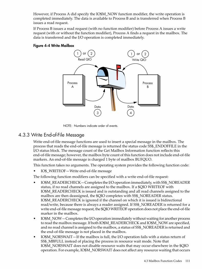
However, if Process A did specify the IO$M_NOW function modifier, the write operation iscompleted immediately. The data is available to Process B and is transferred when Process Bissues a read request.If Process B issues a read request (with no function modifier) before Process A issues a writerequest (with or without the function modifier), Process A finds a request in the mailbox. Thedata is transferred and the I/O operation is completed immediately.
Figure 4-4 Write Mailbox
Read QIO Write QIO
1
Data
3
Data
4
2or 1 2or
ProcessA
NOTE: Numbers indicate order of events.
ProcessB
4.3.3 Write End-of-File MessageWrite end-of-file message functions are used to insert a special message in the mailbox. Theprocess that reads the end-of-file message is returned the status code SS$_ENDOFFILE in theI/O status block. The message count of the Get Mailbox Information function reflects thisend-of-file message; however, the mailbox byte count of this function does not include end-of-filemarkers. An end-of-file message is charged 1 byte of mailbox BUFQUO.This function takes no arguments. The operating system provides the following function code:• IO$_WRITEOF—Write end-of-file messageThe following function modifiers can be specified with a write end-of-file request:• IO$M_READERCHECK—Completes the I/O operation immediately, with SS$_NOREADER
status, if no read channels are assigned to the mailbox. If a $QIO WRITEOF withIO$M_READERCHECK is issued and is outstanding and all read channels assigned to themailbox are then deassigned, the $QIO completes with SS$_NOREADER status.IO$M_READERCHECK is ignored if the channel on which it is issued is bidirectionalread/write, because there is always a reader assigned. If SS$_NOREADER is returned for awrite end-of-file message request, the $QIO WRITEOF operation does not place the end-of-filemarker in the mailbox.
• IO$M_NOW—Completes the I/O operation immediately without waiting for another processto read the mailbox message. If both IO$M_READERCHECK and IO$M_NOW are specified,and no read channel is assigned to the mailbox, a status of SS$_NOREADER is returned andthe end-of-file message is not placed in the mailbox.
• IO$M_NORSWAIT—If the mailbox is full, the I/O operation fails with a status return ofSS$_MBFULL instead of placing the process in resource wait mode. Note thatIO$M_NORSWAIT does not disable resource waits that may occur elsewhere in the $QIOoperation. For example, IO$M_NORSWAIT does not affect any resource waiting that occurs
4.3 Mailbox Function Codes 111

when I/O processing routines try to allocate an I/O request packet while passing the I/Orequest to the mailbox driver.
4.3.4 Set Attention ASTSet attention AST functions specify that an asynchronous system trap (AST) be delivered to therequesting process in the following cases:• When a cooperating process places a read request for which no write request is pending in
a designated mailbox. This is called an unsolicited read request.• When a cooperating process places a write request for which no read request is pending in
a designated mailbox. This is called an unsolicited write request.• When room becomes available in the mailbox.If a message exists in the mailbox when a request to enable a write attention AST is issued, theAST routine is activated immediately. If no message exists, the AST is delivered when a writerequest message arrives; therefore, the requesting process need not repeatedly check the mailboxstatus. You must have both logical I/O and read access to the mailbox prior to performing a setattention AST function.The operating system provides the following function codes:• IO$_SETMODE!IO$M_READATTN—Read attention AST• IO$_SETMODE!IO$M_WRTATTN—Write attention AST• IO$_SETMODE!IO$M_MB_ROOM_NOTIFY—Room in the mailbox attention ASTThese function codes take the following device- or function-dependent arguments:• P1—AST address (request notification is disabled if the address is 0)• P2—AST parameter returned in the argument list when the AST service routine is called• P3—Access mode to deliver AST; maximized with requester's modeThese functions are enabled only once; they must be explicitly reenabled after the AST has beendelivered if you desire repeat notification. All types of enable functions, and more than one ofeach type, can be set at the same time. The number of enable functions is limited only by the ASTquota for the process.Figure 4-5 shows the write attention AST function. In this figure, an AST is set to notify ProcessA when Process B sends an unsolicited message.
112 Mailbox Driver

Figure 4-5 Write Attention AST (Read Unsolicited Data)
Read QIO andIO$M_NOW
AST specified byIO$_SETMODE
!IO$M+WRTATTNUnsolicitedWrite QIO
1
Data
6 2
Data
25
3
4
ProcessA
AST
NOTE: Numbers indicate order of events.
ProcessB
Process A uses the IO$_SETMODE!IO$M_WRTATTN function to request an AST. When ProcessB sends a message to the mailbox, the AST is delivered to Process A. Process A responds to theAST by issuing a read request to the mailbox. The data is then transferred to complete the I/Ooperation.If several requesting processes have set ASTs for unsolicited messages at the same mailbox, allASTs are delivered when the first unsolicited message is placed in the mailbox; however, onlythe first process to respond to the AST with a read request receives the data. Therefore, whenthe next process to respond to an AST issues a read request to the mailbox, it might find themailbox empty. If this request does not include the function modifier IO$M_NOW, it is queuedbefore the next message arrives in the mailbox.Figure 4-6 shows the read attention AST function. In this figure, an AST is set to notify ProcessA when Process B issues a read request for which no message is available.
4.3 Mailbox Function Codes 113

Figure 4-6 Read Attention AST
Write QIO andIO$M_NOW
AST specified byIO$_SETMODE
!IO$M+WRTATTN Read QIO1
Data
5 6
Data
25
3
4
ProcessA
AST
NOTE: Numbers indicate order of events.
ProcessB
Process A uses the IO$_SETMODE!IO$M_READATTN function to specify an AST. When ProcessB issues a read request to the mailbox, the AST is delivered to Process A. Process A responds tothe AST by sending a message to the mailbox. The data is then transferred to complete the I/Ooperation.If several requesting processes set ASTs for read requests for the same mailbox, all ASTs aredelivered when the first read request is placed in the mailbox. Only the first process to respondwith a write request is able to transfer data to Process B.
4.3.5 Wait for Writer/ReaderThe wait for writer/reader mailbox driver function waits until a channel is assigned to the mailboxwith the requested access direction. This function returns immediately if a channel is alreadyassigned to the mailbox with the proper access direction. This function always returns immediatelyif issued on a bidirectional mailbox channel. Any channel assigned bidirectionally to the mailboxsatisfies both types of wait requests.The wait function requires the same synchronization techniques as all other $QIO functions.$QIO Wait should not be issued without any synchronization of its completion. If nosynchronization is performed, the program behaves as if no $QIO Wait function had been issued(except for the small delay caused by issuing the $QIO Wait).The following function codes and modifiers are provided:• IO$_SETMODE!IO$M_READERWAIT—Waits for a read channel to be assigned to the
mailbox.• IO$_SETMODE!IO$M_WRITERWAIT—Waits for a write channel to be assigned to the
mailbox.These function codes require no function-dependent arguments.These functions are enabled only once. Once the $QIO operation completes, these functions mustbe explicitly reenabled.
114 Mailbox Driver
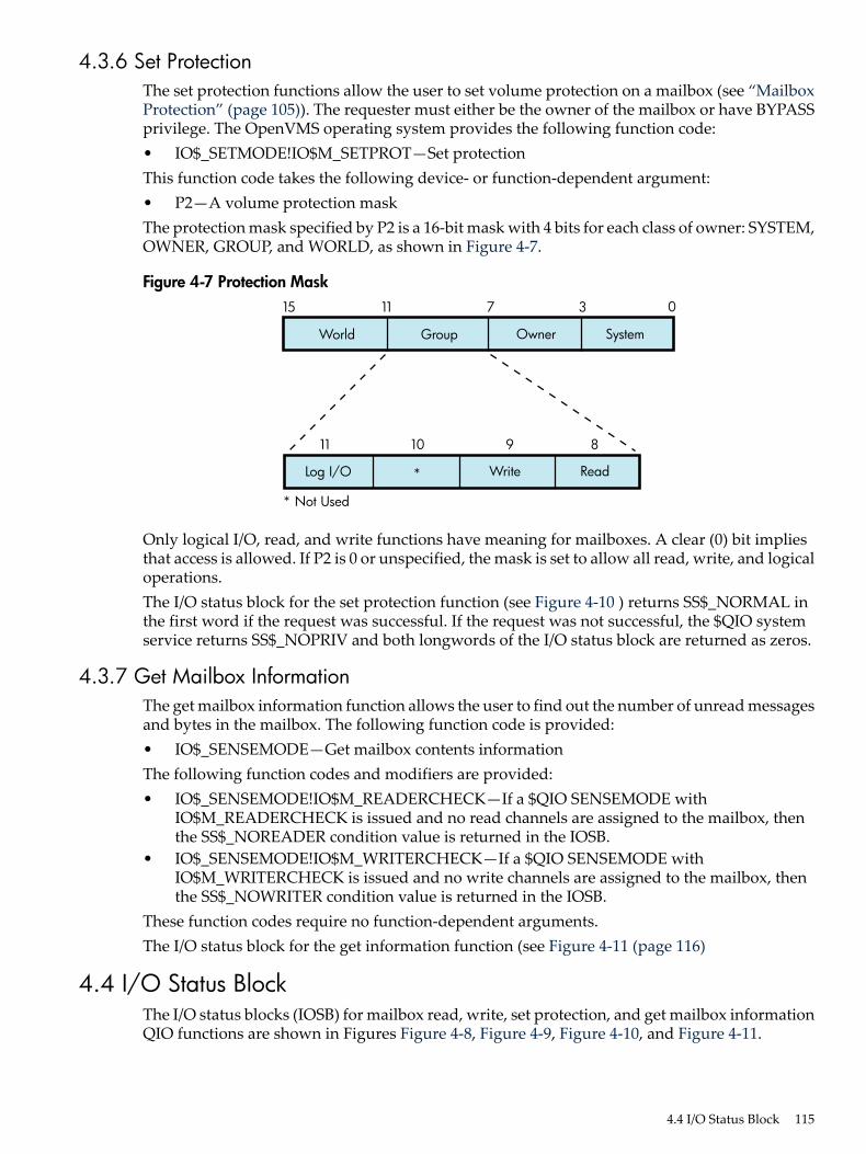
4.3.6 Set ProtectionThe set protection functions allow the user to set volume protection on a mailbox (see “MailboxProtection” (page 105)). The requester must either be the owner of the mailbox or have BYPASSprivilege. The OpenVMS operating system provides the following function code:• IO$_SETMODE!IO$M_SETPROT—Set protectionThis function code takes the following device- or function-dependent argument:• P2—A volume protection maskThe protection mask specified by P2 is a 16-bit mask with 4 bits for each class of owner: SYSTEM,OWNER, GROUP, and WORLD, as shown in Figure 4-7.
Figure 4-7 Protection Mask
World Group
* Not Used
Owner System
1115 37 0
Log I/O * Write Read
1011 89
Only logical I/O, read, and write functions have meaning for mailboxes. A clear (0) bit impliesthat access is allowed. If P2 is 0 or unspecified, the mask is set to allow all read, write, and logicaloperations.The I/O status block for the set protection function (see Figure 4-10 ) returns SS$_NORMAL inthe first word if the request was successful. If the request was not successful, the $QIO systemservice returns SS$_NOPRIV and both longwords of the I/O status block are returned as zeros.
4.3.7 Get Mailbox InformationThe get mailbox information function allows the user to find out the number of unread messagesand bytes in the mailbox. The following function code is provided:• IO$_SENSEMODE—Get mailbox contents informationThe following function codes and modifiers are provided:• IO$_SENSEMODE!IO$M_READERCHECK—If a $QIO SENSEMODE with
IO$M_READERCHECK is issued and no read channels are assigned to the mailbox, thenthe SS$_NOREADER condition value is returned in the IOSB.
• IO$_SENSEMODE!IO$M_WRITERCHECK—If a $QIO SENSEMODE withIO$M_WRITERCHECK is issued and no write channels are assigned to the mailbox, thenthe SS$_NOWRITER condition value is returned in the IOSB.
These function codes require no function-dependent arguments.The I/O status block for the get information function (see Figure 4-11 (page 116)
4.4 I/O Status BlockThe I/O status blocks (IOSB) for mailbox read, write, set protection, and get mailbox informationQIO functions are shown in Figures Figure 4-8, Figure 4-9, Figure 4-10, and Figure 4-11.
4.4 I/O Status Block 115
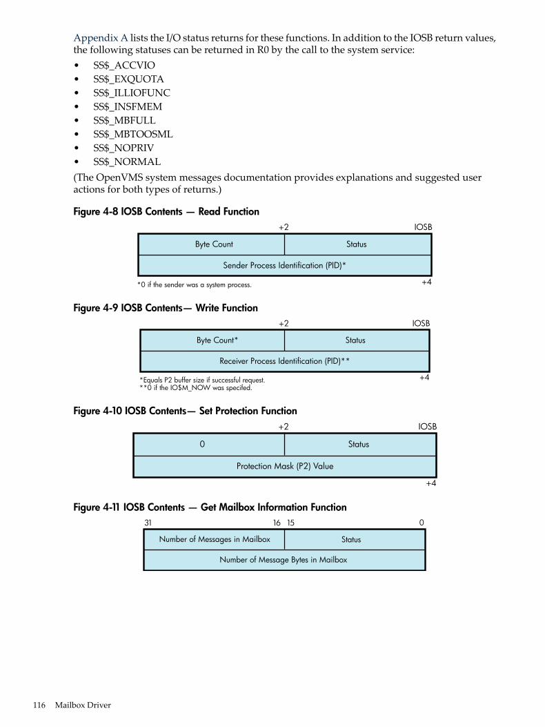
Appendix A lists the I/O status returns for these functions. In addition to the IOSB return values,the following statuses can be returned in R0 by the call to the system service:• SS$_ACCVIO• SS$_EXQUOTA• SS$_ILLIOFUNC• SS$_INSFMEM• SS$_MBFULL• SS$_MBTOOSML• SS$_NOPRIV• SS$_NORMAL(The OpenVMS system messages documentation provides explanations and suggested useractions for both types of returns.)
Figure 4-8 IOSB Contents — Read Function
Byte Count
Sender Process Identification (PID)*
*0 if the sender was a system process.
Status
+2
+4
IOSB
Figure 4-9 IOSB Contents— Write Function
Byte Count*
Receiver Process Identification (PID)**
*Equals P2 buffer size if successful request.**0 if the IO$M_NOW was specifed.
Status
+2
+4
IOSB
Figure 4-10 IOSB Contents— Set Protection Function
0
Protection Mask (P2) Value
Status
+2
+4
IOSB
Figure 4-11 IOSB Contents — Get Mailbox Information Function
Number of Messages in Mailbox
Number of Message Bytes in Mailbox
Status
31 16 15 0
116 Mailbox Driver

4.5 Mailbox Driver Programming ExamplesThis section contains the following programming examples:• Example 4-1 shows a MACRO32 program that creates a mailbox and puts mail into it.• Example 4-2 assigns a read-only channel to the mailbox.• Example 4-3 assigns a write-only channel to the mailbox.Example 4-1 creates a mailbox and puts mail into it; no matching read is pending on the mailbox.First, the program shows that if the function modifier IO$M_NOW is not used when mail isdeposited, the write function waits until a read operation is performed. In this case, IO$M_NOWis specified and the program continues after the mail is left in the mailbox.Next, the mailbox is read. If there is no mail in the mailbox, the program waits becauseIO$M_NOW is not specified. IO$M_NOW should be specified if there is any doubt about theavailability of data in the mailbox, and it is important for the program not to wait.It is up to the user to coordinate the data that goes into and out of mailboxes. In this example,the process reads its own message. Normally, two mailboxes are used for interprocesscommunication: one for sending data from process A to process B, and one for sending datafrom process B to process A. If a program is arranged in this manner, there is no possibility of aprocess reading its own message.
NOTE: The table for temporary mailbox names can be redefined to be a group table. This allowsthe processes in other jobs with same group number to use the same logical name to access themailbox. For example, LNM$TEMPORARY_MAILBOX can be redefined to any shareable tablethat the process has write access to. In this case, it could be redefined to LNM$GROUP if theprocess has GRPNAM privlege or if the group table allows the process to write to it. See thedescription of the $CREMBX service in the System Services ReferenceManual for more information.
Example 4-2 (Example 4-2 (page 121)) and Example 4-3 (Example 4-3 (page 123)) work togetherfrom two separate processes and show the unidirectional mailbox synchronization features. Withthe default definition of LNM$TEMPORARY_MAILBOX, the logical name for the mailbox iscreated in the job logical name table. The processes running both example programs should bein the same job.Example 4-2 performs the following functions:1. Assigns a read-only channel to the mailbox.2. Waits for another program to assign a writable channel to the mailbox.3. Reads, using the IO$M_WRITERCHECK function modifier, what has been written to the
mailbox. Each record is echoed to SYS$OUTPUT.4. When SS$_NOWRITER is returned from the read operation, goes back to Step 2 and waits
for another writer.Example 4-3 is a writer to the mailbox. It performs the following functions:1. Assigns a write-only channel to the mailbox.2. Waits for a reader.3. Gathers user input until the user enters Ctrl/Z, then writes that input to the mailbox.
4.5 Mailbox Driver Programming Examples 117

Example 4-1 Mailbox Driver Program Example 1
; *********************************************************************;
.TITLE MAILBOX DRIVER PROGRAM EXAMPLE .IDENT /01/
;; Define necessary symbols.;
$IODEF ;Define I/O function codes
;; Allocate storage for necessary data structures.;
;; Allocate output device name string and descriptor.;
DEVICE_DESCR: ; .LONG 20$-10$ ;Length of name string .LONG 10$ ;Address of name string10$: .ASCII /SYS$OUTPUT/ ;Name string of output device20$: ;Reference label
;; Allocate space to store assigned channel number.;
DEVICE_CHANNEL: ; .BLKW 1 ;Channel number
;; Allocate mailbox name string and descriptor.;
MAILBOX_NAME: ; .LONG ENDBOX-NAMEBOX ;Length of name string .LONG NAMEBOX ;Address of name stringNAMEBOX: .ASCII /146_MAIN_ST/ ;Name stringENDBOX: ;Reference label
;; Allocate space to store assigned channel number.;
MAILBOX_CHANNEL: ; .BLKW 1 ;Channel number
;; Allocate space to store the outgoing and incoming messages.;
IN_BOX_BUFFER: ; .BLKB 40 ;Allocate 40 bytes for ;received message IN_LENGTH=.-IN_BOX_BUFFER ;Define input buffer length
OUT_BOX_BUFFER: ; .ASCII /SHEEP ARE VERY DIM/ ;Message to send OUT_LENGTH=.-OUT_BOX_BUFFER ;Define length of message to ;send
118 Mailbox Driver

;; Finally, allocate space for the I/O status quadword.;
STATUS: ; .QUAD 1 ;I/O status quadword
;; *********************************************************************;; Start Program;; *********************************************************************;
;; The program first creates a mailbox and assigns a channel to the; process output device. Then a message is placed in the mailbox and; a message is received from the mailbox (the same message). Finally,; the program prints the contents of the mailbox on the process output; device.;
START: .WORD 0 ;Entry mask $CREMBX_S CHAN=MAILBOX_CHANNEL,- ;Channel is the mailbox PROMSK=#^X0000,- ;No protection BUFQUO=#^X0060,- ;Buffer quota is hex 60 LOGNAM=MAILBOX_NAME,- ;Logical name descriptor MAXMSG=#^X0060 ;Maximum message is hex 60 CMPW #SS$_NORMAL,R0 ;Successful mailbox creation? BSBW ERROR_CHECK ;Find out $ASSIGN_S - ;Assign channel DEVNAM=DEVICE_DESCR,- ;Device descriptor CHAN=DEVICE_CHANNEL ;Channel CMPW #SS$_NORMAL,R0 ;Successful channel assign? BSBW ERROR_CHECK ;Find out
;; The program now writes to the mailbox using a write request that; includes the function modifier IO$M_NOW so that it need not wait for; a read request to the mailbox before continuing to the next step in; the program.;
$QIOW_S FUNC=#IO$_WRITEVBLK!IO$M_NOW,- ;Write message NOW CHAN=MAILBOX_CHANNEL,- ;to the mailbox channel P1=OUT_BOX_BUFFER,- ;Write buffer P2=#OUT_LENGTH ;Buffer length CMPW #SS$_NORMAL,R0 ;Successful write request? BSBW ERROR_CHECK ;Find out
;; Read the mailbox.;
$QIOW_S FUNC=#IO$_READVBLK,- ;Read the message CHAN=MAILBOX_CHANNEL,- ;in the mailbox channel IOSB=STATUS,- ;Define status block to - ;receive message length P1=IN_BOX_BUFFER,- ;Read buffer P2=#IN_LENGTH ;Buffer length CMPW #SS$_NORMAL,R0 ;Successful read request? BSBW ERROR_CHECK ;Find out
4.5 Mailbox Driver Programming Examples 119

;; The program now determines how much mail is in the mailbox (this; information is in STATUS+2) and then prints the mailbox message on; the process output device.;
MOVZWL STATUS+2,R2 ;Byte count into R2 $QIOW_S FUNC=#IO$_WRITEVBLK,- ;Write function to the CHAN=DEVICE_CHANNEL,- ;output device channel P1=IN_BOX_BUFFER,- ;Address of buffer to write P2=R2,- ;How much to write P4=#32 ;Carriage control
;; Finally, deassign the channel and exit.;
EXIT: $DASSGN_S CHAN=DEVICE_CHANNEL ;Deassign channel RET ;Return
;; This is the error-checking part of the program. Normally, some kind; of error recovery would be attempted at this point if an error was; detected. However, this example program simply exits.;
ERROR_CHECK: ; BNEQ EXIT ;System service failure, exit RSB ;Otherwise, return
.END START
Example 4-2 assigns a read-only channel to the mailbox.
120 Mailbox Driver

Example 4-2 Mailbox Driver Program Example 2
/* * MAILBOX_READER.C * C program to demonstrate features of the Mailbox driver. * This program is a Mailbox READER. It assigns a READ_ONLY channel to the * mailbox. Its partner program is a Mailbox WRITER. * Compile with Compaq C on VAX or Alpha systems: * $ CC MAILBOX_READER * $ LINK MAILBOX_READER * /#include <stdio.h> /* Standard C I/O */#include <descrip.h> /* Descriptor structure definitions */#include <lib$routines.h> /* LIB$ RTL function definitions */#include <starlet.h> /* System service definitions */#include <ssdef.h> /* System Service status code definitions */#include <cmbdef.h> /* CREMBX definitions */#include <efndef.h> /* Event Flag definitions */#include <iodef.h> /* I/O definitions */
#define $ARRAY_DESCRIPTOR(name,size,array_name) \ static char array_name[ size ]; \ struct dsc$descriptor_s name = \ { size, DSC$K_DTYPE_T, DSC$K_CLASS_S, array_name }int main(void){/* * Message limits are intentionally small to facilitate demonstration of * error conditions. */#define max_msg_len 64 /* Maximum output string size */#define mailbox_maxmsg 64 /* Maximum mailbox message size */#define mailbox_bufquo 128 /* Total buffer space in mailbox */$DESCRIPTOR(mailbox_name_desc,"MAILBOX_EXAMPLE");$DESCRIPTOR(EOF_string_desc, "End of file read ... waiting for another WRITER");$ARRAY_DESCRIPTOR(read_buffer_desc,max_msg_len,read_buffer);
#pragma member_alignment save#pragma nomember_alignment LONGWORD struct io_status_block { /* I/O status block */ unsigned short int condition; unsigned short int count; unsigned int dev; } iosb;#pragma member_alignment restore
int status, mailbox_channel;
/* * Create a temporary mailbox with a READONLY channel. Its logical name * will be entered into the LNM$TEMPORARY_MAILBOX logical name table. */
status = sys$crembx(0,&mailbox_channel,mailbox_maxmsg,mailbox_bufquo, 0,0,&mailbox_name_desc,CMB$M_READONLY); if (status != SS$_NORMAL) (void) lib$signal(status);
/* * Mark the mailbox for deletion. This step is not necessary for a temporary * mailbox, but is included as an illustration. */ (void) sys$delmbx(mailbox_channel);/* * Loop forever, first waiting until a WRITE channel is assigned to the mailbox * and then reading data from it until the WRITER deassigns. */ while (TRUE) { /* First, check to see if there is a WRITER assigned to the mailbox */ status = sys$qiow(
4.5 Mailbox Driver Programming Examples 121

EFN$C_ENF, mailbox_channel, IO$_SENSEMODE|IO$M_WRITERCHECK, &iosb, 0,0, 0,0,0,0,0,0);
/* If there was no WRITER, then wait for one.*/ if ((unsigned int) iosb.condition == SS$_NOWRITER) status = sys$qiow( EFN$C_ENF, mailbox_channel, IO$_SETMODE|IO$M_WRITERWAIT, &iosb, 0,0, 0,0,0,0,0,0);
/* * While the status is good, READ from the mailbox, and echo the * data to SYS$OUTPUT. */ while (status == SS$_NORMAL) { status = sys$qiow( EFN$C_ENF, mailbox_channel, IO$_READVBLK|IO$M_WRITERCHECK, &iosb, 0,0, read_buffer_desc.dsc$a_pointer,max_msg_len, 0,0,0,0); if (status != SS$_NORMAL) (void) lib$signal(status); status = iosb.condition;
if (status == SS$_NORMAL) { read_buffer_desc.dsc$w_length = iosb.count; (void) lib$put_output(&read_buffer_desc); } else if (status == SS$_ENDOFFILE) { (void) lib$put_output(&EOF_string_desc); } } }}
Example 4-3 assigns a write-only channel to the mailbox.
122 Mailbox Driver

Example 4-3 Mailbox Driver Program Example 3
/* * MAILBOX_WRITER.C * C program to demonstrate features of the Mailbox driver. * This program is a Mailbox WRITER. It assigns a WRITE_ONLY channel to the * mailbox. It's partner program is a Mailbox READER. * Compile with Compaq C on VAX or Alpha systems: * $ CC MAILBOX_WRITER * $ LINK MAILBOX_WRITER */
#include <stdio.h> /* Standard C I/O */#include <descrip.h> /* Descriptor structure definitions */#include <lib$routines.h> /* LIB$ RTL function definitions */#include <rmsdef.h> /* RMS status code definitions */#include <starlet.h> /* System service definitions */#include <ssdef.h> /* System Service status code definitions */#include <cmbdef.h> /* CREMBX definitions */#include <efndef.h> /* Event Flag definitions */#include <iodef.h> /* I/O definitions */
#define $ARRAY_DESCRIPTOR(name,size,array_name) \ static char array_name[ size ]; \ struct dsc$descriptor_s name = \ { size, DSC$K_DTYPE_T, DSC$K_CLASS_S, array_name }
void enable_room_ast(int mailbox_channel, int efn);void more_room_ast(int efn);
volatile int ast_enabled = FALSE;int main(void){/* * Message limits are intentionally small to facilitate demonstration of * error conditions. */#define max_msg_len 128 /* Maximum input string size */#define mailbox_maxmsg 64 /* Maximum mailbox message size */#define mailbox_bufquo 128 /* Total buffer space in mailbox */$DESCRIPTOR(mailbox_name_desc,"MAILBOX_EXAMPLE");$DESCRIPTOR(prompt_string_desc, "DATA TO SEND TO MAILBOX (<CTRL Z> to terminate) >>>");$ARRAY_DESCRIPTOR(write_buffer_desc,max_msg_len,write_buffer);
#pragma member_alignment save#pragma nomember_alignment LONGWORDstruct io_status_block { /* I/O status block */ unsigned short int condition; unsigned short int count; unsigned int dev; } iosb;#pragma member_alignment restore
int status, mailbox_channel, wait_efn;
/* * Create a temporary mailbox with a WRITEONLY channel. Its logical name * will be entered into the LNM$TEMPORARY_MAILBOX logical name table. */
status = sys$crembx(0,&mailbox_channel,mailbox_maxmsg,mailbox_bufquo, 0,0,&mailbox_name_desc,CMB$M_WRITEONLY); if (status != SS$_NORMAL) (void) lib$signal(status);
/* * Mark the mailbox for deletion. This step is not necessary for a temporary * mailbox, but is included as an illustration. */ (void) sys$delmbx(mailbox_channel);
/*
4.5 Mailbox Driver Programming Examples 123

* Reserve an event flag to use with "room in mailbox" AST notifications. */ status = lib$get_ef(&wait_efn); if (status != SS$_NORMAL) (void) lib$signal(status);
/* * Loop forever, first waiting until a READ channel is assigned to the mailbox * and then write data until there is no more data to write. */ while (TRUE) { /* * Wait for a READER to assign a channel. If a READER is already * assigned, this will return immediately. */ status = sys$qiow( EFN$C_ENF, mailbox_channel, IO$_SETMODE|IO$M_READERWAIT, &iosb, 0,0, 0,0,0,0,0,0); while (status) { write_buffer_desc.dsc$w_length = max_msg_len; status = lib$get_input( &write_buffer_desc, &prompt_string_desc, &write_buffer_desc.dsc$w_length);
/* If at end of file (user typed <CTRL Z>) then write EOF to * the mailbox, deassign the channel, and exit. * The writer should not deassign the channel while the write EOF * operation is pending, since the write would be cancelled and * the reader would never receive the EOF. Omitting IO$M_NOW in * this QIOW insures that it will not complete until the reader * has actually read the EOF from the mailbox. */ if (status == RMS$_EOF) { (void) sys$qiow( EFN$C_ENF, mailbox_channel, IO$_WRITEOF|IO$M_READERCHECK, &iosb, 0,0,0,0, 0,0,0,0); (void) sys$dassgn(mailbox_channel); (void) sys$exit(SS$_NORMAL); }
/* Write the message into the mailbox. If there isn't enough * room, try again until it fits. * Note that if the NORSWAIT function modifier had been eliminated * below, then the ROOM_NOTIFY and the retry loop could have been * removed. ROOM_NOTIFY was used in this example simply to show * its use. It would be more appropriately used when the program * has other things it can be working on, as opposed to the * example below in which the program is not doing anything except * WAITING for room in the mailbox. */ do { status = sys$qiow( EFN$C_ENF, mailbox_channel, IO$_WRITEVBLK|IO$M_READERCHECK|IO$M_NOW|IO$M_NORSWAIT, &iosb, 0,0, write_buffer_desc.dsc$a_pointer, write_buffer_desc.dsc$w_length, 0,0,0,0);
124 Mailbox Driver

if (status == SS$_NORMAL) { /* If there is no longer a reader, just exit. */ if ((unsigned int) iosb.condition == SS$_NOREADER) { (void) sys$dassgn(mailbox_channel); (void) sys$exit(iosb.condition); } } else if (status == SS$_MBFULL) { if (ast_enabled) /* * Wait here until the AST routine sets the event * flag. A read might have already occurred, in which * case the wait will return immediately. */ (void) sys$waitfr(wait_efn); else /* * The mailbox was full a moment ago at the time of * write, but a read might have already occurred and * the mailbox might be empty now. It is possible * that no more reads will complete (and deliver * the AST) before the next write. So enable the AST * and try the write one more time before waiting for * the event flag. */ enable_room_ast(mailbox_channel, wait_efn); } else /* An unexpected error condition */ (void) lib$signal(status); } while (status != SS$_NORMAL); } }}void enable_room_ast(int mailbox_channel, int efn)/* * This routine requests AST delivery when there is room in the mailbox. * AST delivery may be triggered by a read or a cancelled I/O. */{ int status;
ast_enabled = TRUE; status = sys$clref(efn);
/* * This QIOW returns immediately, whether there is room in the mailbox * or not. Even if there is room in the mailbox now, the AST is * NOT delivered immediately, but only later when a read or cancel * I/O occurs on the mailbox. */ status = sys$qiow( EFN$C_ENF, mailbox_channel, IO$_SETMODE|IO$M_MB_ROOM_NOTIFY, 0,0,0, more_room_ast,efn,0,0,0,0);}void more_room_ast(int efn)/* * This AST routine is called when there is room to write more data into * the mailbox. */{ ast_enabled = FALSE; (void) sys$setef(efn);}
4.5 Mailbox Driver Programming Examples 125

126

5 Terminal DriverThis chapter describes the use of the terminal driver (TTDRIVER) and the LAT port driver(LTDRIVER). The terminal driver supports the asynchronous, serial line multiplexers.The terminaldriver also supports the console terminal. The LAT port driver accommodates I/O requests fromapplication programs; for example to make connections to remote devices, such as a printer, ona server (see “LAT Port Driver QIO Interface” (page 163)).
5.1 Terminal Driver FeaturesThe terminal driver provides the following features:• Input processing
— Command-line editing and command recall— Control characters and special keys— Input character validation (read verify)— American National Standard Institute (ANSI) escape sequence detection— Type-ahead feature— Specifiable or default input terminators— Special operating modes, such as NOECHO and PASTHRU
• Output processing— Efficiency— Limited full-duplex operation— Formatted or unformatted output
• Dialup support— Modem control— Hangup on logout— Preservation of process across hangups
• Miscellaneous— Terminal/mailbox interaction— Autobaud detection— Out-of-band control character handling
NOTE: Not all terminal controllers support all terminal driver capabilities.
5.1.1 Input ProcessingThe terminal driver defines many terminal characteristics and read function modifiers, whichprovide a wide range of options to an application program. These options allow multiple levelsof control over the terminal driver's input process, ranging from the default of command-lineediting that provides a highly flexible user interface, to the PASTHRU mode, which inhibitsinput process interpretation of data.
5.1.1.1 Command-Line Editing and Command RecallThe terminal driver input process defines a bounded set of line editing functions. You can accessthese functions with control keys on all keyboards, and with some special keys on certainkeyboards as well. You can move the cursor in single-character increments (left arrow or Ctrl/D,right arrow or Ctrl/F) or in multicharacter increments, to the beginning of the line (Ctrl/H) orend of the line (Ctrl/E). The terminal driver supports both insert character and overstrike charactermodes. The insert or overstrike mode is the terminal's default characteristic1 at the beginning of
1. HP suggests that new users specify overstrike mode.
5.1 Terminal Driver Features 127

a read operation, but you can change it with the toggle insert/overstrike key (Ctrl/A). You candelete characters in word increments (Ctrl/J or line feed) and beginning-of-the-line increments(Ctrl/U).When you use the terminal driver's editing functions, the following restrictions result:• You cannot move the cursor to a previous line after a line wrap.• You cannot insert a character if the insertion would force a line wrap or if a tab follows the
current cursor position.• You cannot delete a word at the beginning of a line after a line wrap.• You cannot assign the line editing function to other keys.Command recall, initiated by Ctrl/B or the up arrow, returns the last line entered to thecommand-line buffer. At this point, you edit or reenter the line by pressing the Return key. DCLextends command recall up to the last 254 commands by using the TRM$M_TM_NORECALLmodifier to disable the terminal driver's recall mechanism.Any control key that is not defined by line editing is ignored. For application programs thatrequire control key input but do not perform QIO functions with special read modifiers, the SETTERMINAL/NOLINE_EDIT DCL command disables command-line editing.
5.1.1.2 Control Characters and Special KeysA control character is a character that controls action at the terminal rather than passing data toa process. An ASCII control character has a code between 0 and 31, and 127 (hexadecimal 0through 1F, and 7F); that is, all normal control characters plus DELETE. (Table C-1 lists thenumeric values for all control characters.)You enter some control characters at the terminal by simultaneously pressing the Ctrl key anda character key, such as Ctrl/x. Table 5-1 lists the terminal control characters. You can changecontrol character echo strings (Ctrl/C, Ctrl/Y, Ctrl/O, and Ctrl/Z) on a systemwide basis (see theHP OpenVMS System Management Utilities Reference Manual). You enter special keys, such asReturn, Line Feed, and Escape, by pressing a single key.Several of the control characters do not function as described if the DCL command SETTERMINAL/LINE_EDIT is not specified. See the HP OpenVMS DCL Dictionary for informationon line editing function keys and the SET TERMINAL command.
128 Terminal Driver

Table 5-1 Terminal Control Characters
MeaningControl Character
Gains the attention of the enabling process if the user program has enabled a Ctrl/CAST. If a Ctrl/C AST is not enabled, Ctrl/C is converted to Ctrl/Y (see “Enable Ctrl/CAST and Enable Ctrl/Y AST Function Modifiers” (page 159)).The terminal performs a carriage-return/line-feed combination (carriage returnfollowed by a line feed), echoes CANCEL, and performs anothercarriage-return/line-feed combination. If the terminal has the ReGIS characteristic orif Ctrl/Y is pressed, the cancel ReGIS escape sequence is sent.Additional consequences of Ctrl/C are as follows:• The type-ahead buffer is emptied.• Ctrl/S and Ctrl/O are reset.• All queued and in-progress write operations and all in-progress read operations
are successfully completed. The status return is SS$_CONTROLC, orSS$_CONTROLY if Ctrl/C is converted to Ctrl/Y.
The F6 key maps to Ctrl/C on the following terminal types: LK201, LK46W, LK461,LK463, and other compatible LK-series keyboards.Note that Ctrl/C is generally translated to Ctrl/Y for processing within DCL, unlessyou have a Ctrl/C handler. Use LIB$ENABLE_CTRL and LIB$DISABLE_CTRL to getCtrl/C and Ctrl/Y handled within your application. Example 5-4 shows a programmingexample that demonstrates Ctrl/Y and Ctrl/C handling under OpenVMS.
Cancel (Ctrl/C)
Removes the last character entered from the input stream.DELETE (decimal 127 or hexadecimal 7F) is ignored if there are currently no inputcharacters. Hardcopy terminals echo the deleted character enclosed in backslashes.For example, if the character z is deleted,\z\is echoed (the second backslash is echoedafter the next non-DELETE character is entered). Terminals that have theTT$M_SCOPE characteristic echo DELETE by removing the character.
Delete Character (DELETE)
Purges current input data. When Ctrl/U is entered before the end of a read operation,the current input line is deleted. (In the case of a line wrap, Ctrl/U deletes only a lineat a time.) If line editing is enabled (SET TERMINAL/LINE_EDIT is specified), thedata from the beginning of the line to the current cursor position is deleted.
Delete line (Ctrl/U)
Deletes the word before the cursor. Word terminators are all control characters, space,comma, dash, period, and ! ' # $ & ' ( ) + @ [ \ ] ^ {| ~ / : ; = ? (seeAppendix C).
Delete word (Ctrl/J or F13)(Line feed)
Discards output. Action is immediate. All output is discarded until the next readoperation, the next write operation with a IO$M_CANCTRLO modifier, or the receiptof the next Ctrl/O. The terminal echoes OUTPUT OFF. The current write operation(if any) and write operations performed while Ctrl/O is in effect are completed witha status return of SS$_CONTROLO.A second Ctrl/O, which reenables output, echoes OUTPUT ON. Ctrl/C, Ctrl/Y, andCtrl/T cancel Ctrl/O.
Discard output (Ctrl/O)
Moves the cursor to the end of the line.End of line (Ctrl/E)
Echoes EXIT when Ctrl/Z is entered as a read terminator. By convention, Ctrl/Zconstitutes end-of-file.
Exit (Ctrl/Z or F10)
5.1 Terminal Driver Features 129

Table 5-1 Terminal Control Characters (continued)
MeaningControl Character
Ctrl/Y is a special interrupt or attention character that is used to invoke the commandinterpreter for a logged-in process. Ctrl/Y can be enabled with an IO$M_CTRLYASTfunction modifier to a IO$_SETCHAR or IO$_SETMODE function code. The commandinterpreter's Ctrl/Y AST handler always takes precedence over a user program's Ctrl/YAST handlerEntering Ctrl/Y results in an AST to an enabled process to signify that the user enteredCtrl/Y from the terminal. The terminal performs a carriage-return/line-feedcombination, echoes INTERRUPT, and performs another carriage-return/line-feedcombination if the AST and echo are enabled. Ctrl/Y is ignored (and not echoed) ifthe process is not enabled for the AST.Additional consequences of Ctrl/Y are as follows:• The type-ahead buffer is flushed.• Ctrl/S and Ctrl/O are reset.• All queued and in-progress write operations and all in-progress read operations
are successfully completed with a 0 transfer count. The status return isSS$_CONTROLY.
• The cancel ReGIS escape sequence is sent.
Interrupt (Ctrl/Y)
Moves the cursor one position to the left.Move cursor left (Ctrl/D)
Moves the cursor one position to the right.Move cursor right (Ctrl/F)
Moves the cursor to the beginning of the line.Move cursor to beginning ofline (Ctrl/H or F12) (Backspace)
Purges the type-ahead buffer and performs a Ctrl/U operation. Action is immediate.If a read operation is in progress, the operation is equivalent to Ctrl/U.
Purge type-ahead (Ctrl/X)
Recalls the last command entered. DCL extends recall to several commands.Recall (Ctrl/B or up arrow)
Redisplays current input. When Ctrl/R is entered during a read operation, acarriage-return/line-feed combination is echoed on the terminal, and the currentcontents of the input buffer are displayed. If the current operation is a read withprompt (IO$_READPROMPT) operation, the current prompt string is also displayed.Ctrl/R has no effect if the characteristic TT$M_NOECHO is set.
Redisplay input (Ctrl/R)
Controls data flow; used by terminals and the driver. Restarts data flow to and froma terminal if previously stopped by Ctrl/S. The action occurs immediately with noecho. Ctrl/Q is also used to solicit read operations.Ctrl/Q is meaningless if the line does not have the characteristic TT$M_TTSYNC, thecharacteristic TT$M_READSYNC, or is not currently stopped by Ctrl/S.
Restart output (Ctrl/Q)
If used during a read (input) operation, RET echoes a carriage-return/line-feedcombination. All carriage returns are filled on terminals with TT$M_CRFILL specified.
RET (Return)
Controls data flow; used by both terminals and the terminal driver. Ctrl/S stops alldata flow; the action occurs immediately with no echo. Ctrl/S is also used to stopread operations. Ctrl/S is meaningful only if the terminal has either the TT$M_TTSYNCcharacteristic or the TT$M_READSYNC characteristic.
Stop output (Ctrl/S)
Tabs horizontally. Advances to the next tab stop on terminals with the characteristicTT$M_MECHTAB, but the terminal driver assumes tab stops on MODULO 8(multiples of 8) cursor positions. On terminals without this characteristic, enoughspaces are output to move the cursor to the next MODULO 8 position.
TAB(Ctrl/I)
Displays the current time. Ctrl/T also displays the current node and user name, thename of the image that is running, and information about system resources that havebeen used during the current terminal session.
Status (Ctrl/T)
Changes current edit mode from insert to overstrike, or from overstrike to insert. Thedefault mode (as set with SET TERMINAL/LINE_EDIT) is reset at the beginning ofeach line.
Toggle insert/overstrike(Ctrl/A or F14)
130 Terminal Driver

5.1.1.3 Read VerifyThe read verify instructions provided by the terminal driver allow validation of data as eachcharacter is entered. Invalid characters are not echoed and terminate the operation. The terminaldriver does not support full function field processing. Large data entry applications should useone of the DECforms, FMS, or TDMS layered products, which support the entire data entryenvironment.
5.1.1.4 Escape and Control SequencesEscape and control sequences provide additional terminal control not furnished by the controlcharacters and special keys (see “Control Characters and Special Keys” (page 128)). Escapesequences are strings of two or more characters, beginning with the escape character (decimal27 or hexadecimal 1B), which indicate that control information follows. Many terminals sendand respond to such escape sequences to request special character sets or to indicate the positionof a cursor.The set mode characteristic TT$M_ESCAPE (see Table 5-4) is used to specify that terminal linescan generate valid escape sequences. Also, the read function modifier IO$M_ESCAPE allowsany read operation to terminate on an escape sequence regardless of whether TT$M_ESCAPEis set. If either TT$M_ESCAPE or IO$M_ESCAPE is set, the terminal driver verifies the syntaxof the escape sequences. The sequence is always considered a read function terminator and isreturned in the read buffer; a read buffer can contain other characters that are not part of anescape sequence, but a complete escape sequence always terminates a read operation. The returninformation in the read buffer and the I/O status block includes the position and size of theterminating escape sequence in the data record (see “Read Verify Function” (page 153)).Any escape sequence received from a terminal is checked for correct syntax. If the syntax is notcorrect, SS$_BADESCAPE is returned as the status of the I/O. If the escape sequence does not fitin the user buffer, SS$_PARTESCAPE is returned. If SS$_PARTESCAPE is returned, the applicationprogram must issue enough single-character read requests, without timeout, to read the remainingcharacters in the escape sequence, while parsing the syntax of the rest of the escape sequence.Use of the TRM$_ESCTRMOVR item code prevents SS$_PARTESCAPE errors. No syntax integrityis guaranteed across read operations. Escape sequences are never echoed. Valid escape sequencestake any of the following forms (hexadecimal notation):ESC <int>...<int><fin>(7-bit environment)
CSI <int>...<int><fin>(8-bit environment)
The keywords in the escape sequences indicate the following:
The ESC key, a byte (character) of 1B. This character introduces the escape sequence in a 7-bit environment.ESC
The control sequence introducer, a byte (character) of 9B. This character introduces the escape sequencein a 8-bit environment.
CSI
An “intermediate character” in the range of 20 to 2F. This range includes the space character and 15punctuation marks. An escape sequence can contain any number of intermediate characters, or none.
<int>
A “final character” in the range of 30 to 7E. This range includes uppercase and lowercase letters, numbers,and 13 punctuation marks.
<fin>
Three additional escape sequence forms are as follows:ESC <;> <20-2F>...<30-7E>ESC <20-2F>...<30-7E>ESC <O><20-2F>...<40-7E>
Control sequences, as defined by the ANSI standard, are escape sequences that include controlparameters. Control sequences have the following format:ESC [ <par>...<par><int>...<int><fin>(7-bit environment)
CSI <par>...<par><int>...<int><fin>(8-bit environment)
5.1 Terminal Driver Features 131

The keywords in the control sequences indicate the following:
The ESC key, a byte (character) of 1B.ESC
A control sequence, a byte (character) of 5B.[
The control sequence introducer, a byte (character) of 9B.CSI
A parameter specifier in the range of 30 to 3F.<par>
An “intermediate character” in the range of 20 to 2F.<int>
A “final character” in the range of 40 to 7E.<fin>
For example, the position cursor control sequence is ESC [ Pl ; Pc H where Pl is the desired lineposition and Pc is the desired column position.The user guides for the various terminals list valid escape and control sequences. For example,the VT100 User Guide lists the escape and control sequences for VT100 terminals.“Control Characters and Special Keys” (page 128) describes control character functions duringescape sequences.Table C-2 lists the valid ANSI and DIGITAL private escape sequences for terminals that havethe TT2$M_ANSICRT, TT2$M_DECCRT, TT2$M_DECCRT2, TT2$M_AVO, TT2$M_EDIT, andTT2$M_BLOCK characteristics (see Table 5-5). Table C-2 also lists assumed and selectable ANSImodes and selectable DIGITAL private modes. Only the names of the escape sequences andmodes are listed (for more information, see the specific user guide for the various terminals).Unless otherwise noted, the operation of escape sequences and modes is identical to the particularterminals that implement these features.
5.1.1.5 Type-Ahead FeatureInput (data received) from a terminal is always independent of concurrent output (data sent) toa terminal. This feature is called type-ahead. Type-ahead is allowed on all terminals, unlessexplicitly disabled by the set mode characteristic, inhibit type-ahead (TT$M_NOTYPEAHD; seeTable 5-4 and “Set Mode” (page 156)).Data entered at the terminal is retained in the type-ahead buffer until the user program issuesan I/O request for a read operation. At that time, the data is transferred to the program bufferand echoed at the terminal where it was typed.Deferring the echo until the read operation is active allows the user process to specify functioncode modifiers that modify the read operation. These modifiers can include, for example, noecho(IO$M_NOECHO) and convert lowercase characters to uppercase (IO$M_CVTLOW) (seeTable 5-6).If a read operation is already in progress when the data is typed at the terminal, the data transferand echo are immediate.The action of the driver when the type-ahead buffer fills depends on the set mode characteristicTT$M_HOSTSYNC (see Table 5-4 and “Set Mode” (page 156)). If TT$M_HOSTSYNC is not set,Ctrl/G (bell) is returned to inform you that the type-ahead buffer is full. The buffer must then beemptied, at which time a status of SS$_DATAOVERUN is returned. If TT$M_HOSTSYNC is set,the driver stops input by sending a Ctrl/S and the terminal responds by sending no morecharacters. These warning operations begin eight characters before the type-ahead buffer fillsunless the TT2$M_ALTYPEAHD characteristic is set. In that case, the system generation parameterTTY_ALTALARM is used. The driver sends a Ctrl/Q to restart transmission when the type-aheadbuffer empties completely, and the user has posted another READ QIO.The type-ahead buffer length is variable, with possible values in the range of 0 through 32,767.The length can be set on a systemwide basis through use of the system generation parameterTTY_TYPAHDSZ. Terminal lines that do a large amount of bulk input should use the characteristicTT2$M_ALTYPEAHD, which allows the use of a larger type-ahead buffer specified by the systemgeneration parameters TTY_ALTYPAHD and TTY_ALTALARM. (TTY_ALTYPAHD specifies
132 Terminal Driver
the total size of the alternate type-ahead buffer; TTY_ALTALARM specifies the threshold atwhich a Ctrl/S is sent.)Certain input-intensive applications, such as block mode input terminals, can take advantage ofan optimization in the driver. If a terminal has the characteristic TT2$M_PASTHRU and the readfunction IO$M_NOECHO is specified, data is placed directly into the read buffer and therebyeliminates the overhead for moving the data from the type-ahead buffer.
5.1.1.6 Line TerminatorsA line terminator is the control sequence that you type at the terminal to indicate the end of aninput line. Optionally, the application can specify a particular line terminator or class ofterminators for read operations.Terminators are specified by an argument to the QIO request for a read operation. By default,they can be any ASCII control character except FF, VT, LF, TAB, or BS (see Appendix C). If lineediting is enabled, the only terminators are CR, Ctrl/Z, or an escape sequence. Control keys thatdo not have an editing function are nonfunctioning keys. If included in the request, the argumentis a user-selected group of characters (see “Read Function Terminators” (page 148)).All characters are 7-bit ASCII characters unless data is input on an 8-bit terminal (see “Read”(page 147)). The characteristic TT$M_EIGHTBIT determines whether a terminal uses the 7-bit or8-bit character set; see Table 5-4. All input characters (except some special keys; see “ControlCharacters and Special Keys” (page 128)) are tested against the selected terminators. The inputis terminated when a match occurs or your input buffer fills.The terminal driver notifies the job controller to initiate login when it detects a carriage-returnterminator on a line with no current process (provided the line is not a secure server or thetype-ahead feature has not been disabled). A bell character is sent when the notification occurs.A notification character other than the bell character may be specified by setting the systemgeneration parameter TTY_AUTOCHAR.
5.1.1.7 Special Operating ModesThe terminal driver supports many special operating modes for terminal lines. (Table 5-4 andTable 5-5 list these modes.) All special modes are enabled or disabled by the set mode and setcharacteristics functions (see “Set Mode” (page 156)).
5.1.2 Output ProcessingOutput handling is designed to be very efficient in the terminal driver. For example, onmultiplexers that support both silo and direct memory access (DMA) output, the driver considersrecord size to decide dynamically which mode will result in the least overhead. The block sizespecified by the system generation parameter TTY_DMASIZE is the minimum size block thatcan be used in a DMA operation.
5.1.2.1 Duplex ModesThe terminal driver can execute in either half- or full-duplex mode. These modes describe theterminal driver software, specifically the ordering algorithms used to service read and writerequests, not the terminal communication lines.In half-duplex mode, all read and write requests are inserted onto one queue. The terminal driverremoves requests from the head of this queue and executes them one at a time; all requests areexecuted sequentially in the order in which they were issued.In full-duplex mode, read requests (and all other requests except write requests) are insertedonto one queue and write requests onto another. The existence of two queues allows the driverto recognize the presence of two requests, such as a read request and a write request at the sametime. However, the driver does not execute the read request and the write request simultaneously.When it is ready to service a request, the driver decides which request—the read request or thewrite request—to process next.
5.1 Terminal Driver Features 133

The following terms describe the state of a read request:• A read request is active when the terminal driver removes that request from the head of the
I/O queue.• A read request is started when the terminal driver moves the first character into the read
buffer.In the terminal driver, write requests usually have priority. A write request can interrupt anactive, but not started, read request.The terminal driver does not start a read request until all outstanding writes are completed. Thismeans that a read request could be removed from the head of the read queue while write requestsare outstanding, but the first character is not moved into the read buffer until all outstandingwrites are completed.Once a read request is started, all write requests are queued until the read completes. However,during a read operation many write requests can be executed before the first input character isentered at the terminal. Terminal lines that have the TT$M_NOECHO characteristic, or readfunctions that include the IO$M_NOECHO function modifier, do not inhibit write operationsin full-duplex mode.If a write function specifies the IO$M_BREAKTHRU modifier, the write operation is not blocked,even by an active read operation. IO$M_BREAKTHRU does not change the order in which writeoperations are queued.When all I/O requests are entered using the Queue I/O Request and Wait ($QIOW) system service,there can be only one current I/O request at a time. In this case, the order in which requests areserviced is the same for both half- and full-duplex modes.The type-ahead buffer always buffers input data for which there is no current read request, inboth half- and full-duplex modes.
5.1.2.2 Formatting of OutputBy default, output data is subject to formatting by the terminal driver. This formatting includesactions such as wrapping, tab expansion, uppercase, and fallback conversions. Applications thatdo not require formatting of data can write with the IO$M_NOFORMAT modifier and therebyreduce overhead. IO$M_NOFORMAT overrides all formatting except fallback translation. Settingthe PASTHRU mode (TT2$M_PASTHRU) is equivalent to writing with the noformat modifier.Fallback conversions occur regardless of formatting mode.
5.1.2.3 SET HOST Facility and Output BufferingThe SET HOST facility emulates the terminal driver in the way it writes data to the terminal bystopping the display as soon as the abort character is entered. However, the SET HOST facilitybehaves differently from the terminal driver in that it buffers output data from the program thatis executing. Occasionally, this causes a perception problem for the user when the program isaborted with a Ctrl/C, Ctrl/Y, or an out-of-band abort character. The user expects the programto terminate and the display to stop immediately.
CTDRIVER and RTPAD
When used between two systems, the SET HOST facility consists of two components: RTPADon the local node and CTDRIVER on the remote node. Both components buffer output data toenhance performance when using wide area networks. CTDRIVER performs the initial buffering,queues the buffers for network transfer, and returns a successful write status. The user shouldnote that the local terminal display reflects the output of the executing program after the datahas been buffered and transferred over the network—not as the output buffers are filled on theremote node.The delay between execution of an application and the display of its output can lead to severalanomalies in the effects of Ctrl/C, Ctrl/Y, and out-of-band abort characters.
134 Terminal Driver

Output Line Not in Sequence Following an Abort Character
After you enter an abort character (Ctrl/C, Ctrl/Y, or an out-of-band abort character) that causesthe input or output to be aborted, it is possible to receive an additional line of output. This occurswhen the application program calls $QIO (either directly or indirectly through RMS or languagesupport routines) to output data to a buffer at the same time the abort character is entered.When CTDRIVER receives the abort character (Ctrl/C, Ctrl/Y, or an out-of-band abort character)from the network, it flushes the current output buffers and aborts any pending read operations.However, if the application program calls $QIO with a write operation when the abort characteris entered, the $QIO write data is still buffered and then displayed. The data may not be the nextoutput in sequence from the user's point of view, since all the previous output buffers inCTDRIVER were flushed and the data in them was not displayed.When using the terminal driver, the effect of an abort character on the display screen is different.The terminal driver does not buffer output from the application during program execution. Ifthe application program has just called $QIO with a write operation when the abort character isentered, then the $QIO write data is displayed. Because all write operations are sequential anddo not complete until the output is actually displayed, the additional line displayed is in sequence.There is no break in the data. Normally, the user does not notice that there is an additional line.
Extra Input Prompt Following an Abort Character
For connections between systems, the CTERM protocol allows CTDRIVER to synchronize withRTPAD before displaying any more data on the terminal.
Processing Abort Characters
The abort character AST is delivered after the message describing the aborted read operationhas been received. Therefore, the read status should be set very shortly after the abort characterAST is delivered to the application. Note, however, these are still two asynchronous events, andthe application must still synchronize with the completing read operation.
Captive Command Procedures and Ctrl/Y
CTDRIVER and RTPAD emulate the terminal driver in that the current read operation and allpending write operations abort when Ctrl/Y is entered. However, the pending write operationsalso include all the buffered output that occurred and that would have been output before theCtrl/Y was entered but due to the buffering was not.The effect of the buffering can be confusing if a Ctrl/Y is entered when a captive commandprocedure is executing. During execution of captive command procedures, DCL has a Ctrl/Ypending. When this AST is delivered, DCL only reenables it; no other action is performed. Inthat case, if the program being executed only performs output, it appears that the program wasaborted by the Ctrl/Y. Actually, the program completed execution before the Ctrl/Y was entered,and the Ctrl/Y merely discarded all the buffered output.
5.1.3 Dialup SupportThe operating system supports modem control (for example, Bell 103A, Bell 113, or equivalent)for all supported multiplexers in autoanswer, full-duplex mode. The terminal driver does notsupport half-duplex operations on modems such as the Bell 202. Also not supported are modemsthat use circuit 108/1 (connect data set to line signal) in place of the data terminal ready (DTR)signal. Most U.S. and European modems use the data terminal ready signal, which is the signalsupported by the operating system.
5.1 Terminal Driver Features 135

5.1.3.1 Modem Signal ControlDialup lines with the characteristic TT$M_MODEM are monitored periodically to detect a changein the modem carrier signals data set ready (DSR), calling indicator (RING), or request to send(RTS). The system generation parameter TTY_SCANDELTA establishes the dialup monitoringfor multiplexers that do not support modem signal transition interrupts, such as the DZ seriesof controllers.If a line's carrier signal is lost, the driver waits 2 seconds for the carrier signal to return. If bit 0of the system generation parameter TTY_DIALTYPE is set to 1, the driver does not wait. Bit 0 is0 by default for countries with Bell System standards, but that bit should be set to 1 for countrieswith International Telegraph and Telephone Consultative Committee (CCITT) standards. If thecarrier signal is not detected during this time, the line is hung up. The hangup action can signalthe owner of the line, through a mailbox message, that the line is no longer in use. (No dial-inmessage is sent; the unsolicited character message is sufficient when the first available data isreceived.) The line is not available for a minimum of 2 seconds after the hangup sequence begins.The hangup sequence is not reversible. If the line hangs up, all enabled Ctrl/Y and out-of-bandASTs are delivered; the Ctrl/Y AST P2 argument is overwritten with SS$_HANGUP. The I/Ooperation in progress is canceled, and the status value SS$_HANGUP is returned in the I/O statusblock. DCL is responsible for process deletion after Ctrl/Y is delivered. If the process is suspended,DCL cannot run, and therefore deletion cannot occur, until the process is resumed.
NOTE: Some systems provide built-in serial lines using 6-pin modular jacks. These lines donot provide the minimum required modem signals. Although the hardware may allow a dial-outconnection to be established, hangup cannot be detected and process deletion does not occur onthese lines.
For terminals with the TT$M_MODEM characteristic, TT$M_REMOTE reflects the state of thecarrier signal. TT$M_REMOTE is set when the carrier signal changes from off to on, and clearedwhen the carrier signal is lost.A line that does not have TT$M_MODEM set does not respond to modem signals or set the DTRsignal. Modem signals can be set and sensed manually through use of the IO$M_MAINT functionmodifier (see “Set Modem Function Modifier” (page 160)).The terminal driver default modem protocol meets the requirements of the United States and ofEuropean countries. This protocol is capable of working in automatic answer mode and can alsoperform manually dialed outgoing calls. The protocol supports the requirements of most knowninternational telephone networks. Enhanced modem features are used on multiplexers thatsupport them; processor polling is not necessary. The protocol also functions in a subset modefor the multiplexers that do not support full modem signals.Table 5-2 lists the control and data signals used in a full modem control mode configuration (ina two-way simultaneous, symmetrical transmit mode). Figure 5-1 is a flowchart that shows atypical signal sequence for a terminal operation in this mode. The flowchart shows the statesthat the modem transition code goes through to detect different types of transitions in modemstate. These transitions allow the driver to detect loss of lines that have been idle for severalminutes. Modem states do not affect the ability of the system to transmit characters.
136 Terminal Driver

Figure 5-1 Modem Control: Two-Way Simultaneous Operation
Idle
Delay 2 sec
Delay 1 sec
Delay 1 sec
TTY_DIALTYPE=2
CARRIER andCTS and DSR ON
Timeout
Timeout
Timeout
ReferenceCount=0
Reference Count>0
DTR OFF
RING ON
RING ONDSR ON
CARRIER ON
CARRIER ON
CARRIER OFF
DSR OFF
RTS OFFTX MARK
Wait
RING Wait
DZ11 Wait
Init1
DTR ON
RTS ON
Init2DTR ONRTS ON
DZ11
TTY_DIALTYPE=4
TTY_DIALTYPE=1
Start 30sec timer
Transmit0
Start 30sec timerPORT_RESUME
Transmit
Transmit and receive data
Transmit1
Start 2sec timer
Shutdown
DSR OFF
DSR OFF
DTR OFF
Shut1
Start 2sec timer
Set mode function modifiers are provided to allow a process to activate or deactivate modemcontrol signals (see “Set Modem Function Modifier” (page 160)).Bit 1 of the system generation parameter TTY_DIALTYPE enables alternate modem protocol ona systemwide basis. If bit 1 is 0 (the default), the RING signal is not used. If bit 1 is 1, the modemprotocol delays setting the DTR signal until the RING signal is detected.Remote terminal connections have a timeout feature for the security of dialup lines. If no channelis assigned to the port within 30 seconds, or a port with an assigned channel is not allocated, theDTR signal is dropped. Such action prevents an unused terminal from tying up a line. However,there are configurations (such as a printer connected to a remote line) in which the line shouldnot be dropped even though it is not being used interactively. To bypass the 30-second timeout,set the system generation parameter TTY_DIALTYPE to 4. (Note that if TTY_DIALTYPE is equalto 4, all dialup lines skips the timeout waiting for a channel to be assigned.)
5.1 Terminal Driver Features 137

Table 5-2 Control and Data Signals
MeaningSourceSignal
The data originated by the computer and transmitted throughthe modem to one or more remote terminals.
ComputerTransmitted data (TxD)
The data generated by the modem in response to telephone linesignals received from a remote terminal and transferred to thecomputer.
ModemReceived data (RxD)
If present (ON condition), RTS directs the modem to assume thetransmit mode. If not present(OFF condition), RTS directs themodem to assume the nontransmit mode after all transmit datahas been transmitted.
ComputerRequest to send (RTS)
Indicates whether the modem is ready (ON condition) or notready (OFF condition) to transmit data on the telephone line.
ModemClear to send (CTS)
If present (ON condition), DSR indicates that the modem is readyto transmit and receive; that is, the modem is connected to theline and is ready to exchange further control signals with thecomputer to initiate the exchange of data.
ModemData set ready (DSR)
If DSR is not present (OFF condition), the modem is not readyto transmit and receive. If DSR is detected, the operating systeminitiates a 30-second timer. This ensures that the phone line isdisconnected if CARRIER is not detected.
If present (ON condition), CARRIER indicates that the receiveddata channel line signal is within appropriate limits, as specifiedby the modem. If not present (OFF condition), the received signalis not within appropriate limits.
ModemData channel received linesignal detector (CARRIER)
If present (ON condition), DTR indicates that the computer isready to operate, prepares the modem to connect to the telephoneline, and maintains the connection after it has been made byother means. DTR can be present whenever the computer is readyto transmit or receive data. If DTR is not present (OFF condition),the modem disconnects the modem from the line.
ComputerData terminal ready (DTR)
Indicates whether a calling signal is being received by themodem. Bit 1 of the system generation parameterTTY_DIALTYPE must be set (=1). If RING is detected, theoperating system initiates a 30-second timer. This ensures thatthe phone line is disconnected if CARRIER is not detected.
ModemCalling indicator (RING)
5.1.3.2 Hangup on Logging OutBy default, logging out on a line with modem signals will not break the connection. IfTT2$M_HANGUP is set, modem signals are dropped when the process logs out. IfTT2$M_MODHANGUP is set, no privilege is required to change the state of TT2$M_HANGUP.By setting TT2M_HANGUP, system managers can prevent nonprivileged users who are notlogged in from tying up a dial-in line.
138 Terminal Driver
5.1.3.3 Preservation of a Process Across HangupsVirtual terminal support provides disconnectable terminals that allow a connection to a physicalterminal line to be broken without losing the job.On Alpha and Integrity server systems, the following SYSMAN command allows terminals tobe discountable terminals:SYSMAN> IO CONNECT VTA0/NOADAPTER/DRIVER=SYS$TTDRIVER
After this command is entered, a terminal with the TT2$M_DISCONNECT characteristic logs inas VTAn:, rather than with the physical terminal name. When a terminal is set up in this manner,no input or output operations are allowed to the physical device; I/O is automatically redirectedto the appropriate virtual terminal.Following are four ways in which a terminal can become disconnected:• Modem signals between the host and the terminal are lost.• A user presses the BREAK key on a terminal that has the TT2$M_SECURE characteristic.• A user enters the DCL command DISCONNECT.• A user enters the DCL command CONNECT/CONTINUE.After validated as a user, you can connect to a disconnected process in either of the followingways:• Allow the login process to make the connection.• Enter the DCL command CONNECT.
5.1.4 Terminal/Mailbox InteractionMailboxes are virtual I/O devices used to communicate between processes. The terminal I/Odriver can use a mailbox to communicate with a user process. Chapter 4 describes the mailboxdriver.A user program can use the Assign I/O Channel ($ASSIGN) system service to associate a mailboxwith one or more terminals. The terminal driver sends messages to this mailbox whenterminal-related events that require the attention of the user image occur.Mailboxes used in this way carry status messages, not terminal data, from the driver to the userprogram. For example, when data is received from a terminal for which no read request isoutstanding (unsolicited data), a message is sent to the associated mailbox to indicate dataavailability. On receiving this message, the user program reads the channel assigned to theterminal to obtain the data. Messages are sent to mailboxes under the following conditions:• Unsolicited data in the type-ahead buffer. The use of the associated mailbox can be enabled
and disabled as a subfunction of the read and write requests (see “Read” (page 147) and“Write” (page 154)). (Initially, mailbox messages are enabled on all terminals. This is thedefault state.) Therefore, the user process can enter into a dialogue with the terminal afteran unsolicited data message arrives. Then, after the dialogue is over, the user process canreenable the unsolicited data message function on the last I/O exchange. Only one messageis sent between read operations.
• Terminal hangup. When a remote line loses the carrier signal, it hangs up; a message is sentto the mailbox. When hangup occurs on lines that have the characteristic TT$M_REMOTEset, the line returns to local mode.
• Broadcast messages. If the characteristic TT2$M_BRDCSTMBX is set, broadcasts sent to aterminal are placed in the mailbox (this is independent of the state of TT$M_NOBRDCST).
Messages placed in the mailbox have the following content and format (see Figure 5-2):• Message type. The codes MSG$_TRMUNSOLIC (unsolicited data), MSG$_TRMHANGUP
(hangup), and MSG$_TRMBRDCST (terminal broadcast) identify the type of message.Message types are identified by the $MSGDEF macro.
• Device unit number to identify the terminal that sent the message.
5.1 Terminal Driver Features 139

• Counted string to specify the device name.• Controller name.• Message (for broadcasts).
Figure 5-2 Terminal Mailbox Message Format
Unit Number
BroadcastMessage
* Does not include the colon (:) character.
Controller Name*
Message Type
Broadcast Message Length
31 16 15 8 7 0
0
4
8
12
16
20
Counted String
Interaction with a mailbox associated with a terminal occurs through standard QIO functionsand ASTs. Therefore, the process need not have outstanding read requests to an interactiveterminal to respond to the arrival of unsolicited data. The process need only respond when themailbox signals the availability of unsolicited data. Chapter 4 contains an example of mailboxprogramming.The ratio of terminals to mailboxes is not always one to one. One user process can have manyterminals associated with a single mailbox.
5.1.5 Autobaud DetectionIf you specify the /AUTOBAUD qualifier with the SET TERMINAL command, automatic baudrate detection is enabled, allowing the terminal baud rate to be set when you log in. The baudrate is set at login by pressing the Return key two or more times separated by an interval of atleast one second. (Pressing a key other than Return might detect the wrong baud rate; if thisoccurs, wait for the login procedure to time out before continuing.) The supported baud ratesare 110, 150, 300, 600, 1200, 1800, 2400, 3600, 4800, 9600, and 19,200. Most Alpha systems canautobaud up to 57600. Parity is allowed on these lines.The autobaud function works with either even parity or no parity, but not with odd parity. If aline is set to even parity and has 7 bits of data, the line automatically switches to no parity if aterminal not generating parity attempts to log in.The SET TERMINAL qualifier /EIGHT_BIT specifies that the terminal uses 8-bit ASCII code./NOEIGHT_BIT, which is the default, specifies 7-bit ASCII code. (If parity is specified, the paritybit is separate from the data bits.) The optimal settings for automatic baud rate detection on HPterminals are /NOEIGHT_BIT/PARITY=EVEN or /EIGHT_BIT/NOPARITY, although automaticbaud rate detection also works with other combinations, such as /NOEIGHT_BIT/NOPARITY.Table 5-5 describes the terminal characteristic TT2$M_AUTOBAUD, which allows the baud rateto be set automatically at login.HP does not usually recommend specifying the /FRAME qualifier with the SET TERMINALcommand. The terminal driver selects the frame size (the number of data bits that the device can
140 Terminal Driver

transmit) based on how the /PARITY and /EIGHT_BIT qualifiers are set. It might be necessaryto change these values if the terminal is not made by HP.
5.1.6 Out-of-Band Control Character HandlingAll control characters (0 through 1F hexadecimal) can be enabled as out-of-band characters.Typing one of these characters immediately delivers an AST to the requesting process. DCL usesthis mechanism to sense whether Ctrl/T has been entered. Out-of-band character options allowusing the IO$M_INCLUDE function modifier to include the character in the data stream and theIO$M_TT_ABORT function modifier to abort the current input or output operation.
5.2 Terminal Driver Device InformationYou can obtain information on terminal characteristics by using the Get Device/VolumeInformation ($GETDVI) system service. (See the HPOpenVMS System Services Reference Manual.)The sense mode function provides an alternative means to obtain terminal characteristics; see“Sense Mode and Sense Characteristics” (page 186).$GETDVI returns terminal characteristics when you specify the item codes DVI$_DEVCHAR,DVI$_DEVDEPEND, and DVI$_DEVDEPEND2. Table 5-3, Table 5-4, and Table 5-5 list thesecharacteristics. Terminal characteristics are normally set during system generation to any oneof, or a combination of, the values listed in Table 5-4. DVI$_DEVDEPEND returns a longwordfield in which the three low-order bytes contain the device-dependent characteristics and thehigh-order byte contains the page length. Page length can have a value in the range of 0 through255. The $DEVDEF macro defines the device-independent characteristics, the $TTDEF macrodefines the device-dependent characteristics, and the $TT2DEF macro defines the extendeddevice-dependent characteristics.DVI$_DEVCLASS and DVI$_DEVTYPE return the device class and device type names, whichare defined by the $DCDEF and $TTDEF macros, respectively. The device class for terminals isDC$_TERM. The terminal model determines the device type. For example, the device type forthe VT240 is TT$_VT200_SERIES. DVI$_DEVBUFSIZ returns the page width, which can be avalue in the range of 1 through 511. The driver does not accept a value of 0.
Table 5-3 Terminal Device-Independent Characteristics
MeaningCharacteristic
Terminal is on line and available.DEV$M_AVL
Carriage control is enabled.DEV$M_CCL
Terminal is detached.DEV$M_DET
Terminal is capable of input.DEV$M_IDV
Terminal is capable of output.DEV$M_ODV
Terminal is enabled as an operator console.DEV$M_OPR
Device is record-oriented.DEV$M_REC
Terminal has remote terminal UCB extension.DEV$M_RTT
Device is spooled.DEV$M_SPL
Device is a terminal.DEV$M_TRM
Terminal line is allocated for DECnet use.DEV$M_NET
5.2 Terminal Driver Device Information 141

Table 5-4 Terminal Characteristics
MeaningValue1
Terminal requires fill after the Return key is pressed (the fill type can be specifiedby the set mode function P4 argument).
TT$M_CRFILL
Terminal uses the 8-bit ASCII character set (see Appendix C). Terminals withoutthis characteristic use the 7-bit ASCII code. In this case, the eighth bit is maskedout on received characters and is ignored on output characters. The eighth bit ismeaningful only if TT$M_EIGHTBIT is set.
TT$M_EIGHTBIT
Terminal generates escape sequences (see “Escape and Control Sequences”(page 131)). Escape sequences are validated for syntax.
TT$M_ESCAPE
Terminal is in half-duplex mode (see “Duplex Modes” (page 133)). All read andwrite requests are executed sequentially.
TT$M_HALFDUP
The host system is synchronized to the terminal. Ctrl/Q and Ctrl/S are used tocontrol data flow and thus keep the type-ahead buffer from filling.TT$M_HOSTSYNC should always be set on LAT terminals.
TT$M_HOSTSYNC
Terminal requires fill after the line-feed character is processed. (The fill can bespecified by the set mode P4 argument.)
TT$M_LFFILL
Terminal has the lowercase character set. Unless the terminal is in the PASTHRUmode or IO$M_NOFORMAT is specified, all input and echoed lowercasecharacters (hexadecimal 61 to 7A) are converted to uppercase if TT$M_LOWERis not set. (The character ALTMODE (decimal 125 and 126, or hexadecimal 7Dand 7E) converts to ESCAPE on terminals that do not have the lowercasecharacteristic TT$M_LOWER set.)
TT$M_LOWER
Mailboxes associated with the terminal do not receive notification of unsolicitedinput or hangup (see “Dialup Support” (page 135)). This bit can be set by theIO$M_DSABLMBX function modifier for read requests and cleared by theIO$M_ENABLMBX function modifier for write requests.
TT$M_MBXDSABL
Terminal has mechanical form feed. The terminal driver passes form feeds directlyto the terminal instead of expanding to line feeds.
TT$M_MECHFORM
Terminal has mechanical tabs and is capable of tab expansion. To accomplishcorrect line wrapping, the terminal driver assumes there are eight spaces betweentab stops.
TT$M_MECHTAB
Terminal line is connected to a modem. If TT$M_MODEM is set, the terminaldriver automatically handles modem control. If TT$M_MODEM is not set, allmodem signals are ignored. If TT$M_MODEM is set and then cleared, a hangupis declared on the terminal line if that line is in the remote state (TT$M_REMOTEis set). If DTR and RTS are set withIO$_SETMODE!IO$M_SET_MODEM!IO$M_MAINT on a nonmodem port, DTRand RTS goes off and then back on when the port is set for modem.TT$M_MODEM is not supported for LAT devices.
TT$M_MODEM
Terminal does not receive any broadcast messages.TT$M_NOBRDCST
Input characters are not echoed on this terminal line (see “Type-Ahead Feature”(page 132)).
TT$M_NOECHO
Data must be solicited by a read operation. Data is lost if received in the absenceof an outstanding read request (if it is unsolicited data). Disables type-aheadfeature (see “Type-Ahead Feature” (page 132)). If this characteristic is set, loginattempts on this line are disabled. See “Modem Signal Control” (page 136) forinformation on modem signal control.
TT$M_NOTYPEAHD
Read synchronization is enabled. The host explicitly solicits all read operationsby entering a Ctrl/Q and terminates the operation by entering a Ctrl/S.TT$M_READSYNC is not applicable to LAT terminals.
TT$M_READSYNC
142 Terminal Driver
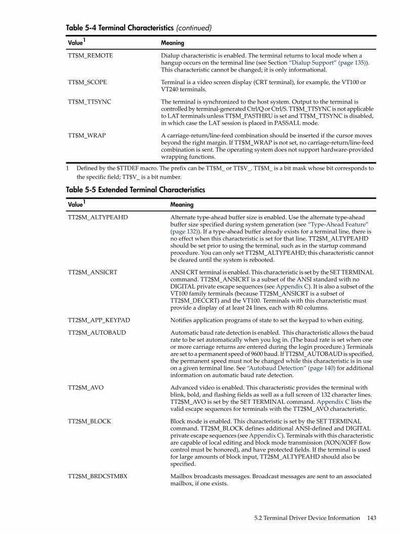
Table 5-4 Terminal Characteristics (continued)
MeaningValue1
Dialup characteristic is enabled. The terminal returns to local mode when ahangup occurs on the terminal line (see Section “Dialup Support” (page 135)).This characteristic cannot be changed; it is only informational.
TT$M_REMOTE
Terminal is a video screen display (CRT terminal), for example, the VT100 orVT240 terminals.
TT$M_SCOPE
The terminal is synchronized to the host system. Output to the terminal iscontrolled by terminal-generated Ctrl/Q or Ctrl/S. TT$M_TTSYNC is not applicableto LAT terminals unless TT$M_PASTHRU is set and TT$M_TTSYNC is disabled,in which case the LAT session is placed in PASSALL mode.
TT$M_TTSYNC
A carriage-return/line-feed combination should be inserted if the cursor movesbeyond the right margin. If TT$M_WRAP is not set, no carriage-return/line-feedcombination is sent. The operating system does not support hardware-providedwrapping functions.
TT$M_WRAP
1 Defined by the $TTDEF macro. The prefix can be TT$M_ or TT$V_. TT$M_ is a bit mask whose bit corresponds tothe specific field; TT$V_ is a bit number.
Table 5-5 Extended Terminal Characteristics
MeaningValue1
Alternate type-ahead buffer size is enabled. Use the alternate type-aheadbuffer size specified during system generation (see “Type-Ahead Feature”(page 132)). If a type-ahead buffer already exists for a terminal line, there isno effect when this characteristic is set for that line. TT2$M_ALTYPEAHDshould be set prior to using the terminal, such as in the startup commandprocedure. You can only set TT2$M_ALTYPEAHD; this characteristic cannotbe cleared until the system is rebooted.
TT2$M_ALTYPEAHD
ANSI CRT terminal is enabled. This characteristic is set by the SET TERMINALcommand. TT2$M_ANSICRT is a subset of the ANSI standard with noDIGITAL private escape sequences (see Appendix C). It is also a subset of theVT100 family terminals (because TT2$M_ANSICRT is a subset ofTT2$M_DECCRT) and the VT100. Terminals with this characteristic mustprovide a display of at least 24 lines, each with 80 columns.
TT2$M_ANSICRT
Notifies application programs of state to set the keypad to when exiting.TT2$M_APP_KEYPAD
Automatic baud rate detection is enabled. This characteristic allows the baudrate to be set automatically when you log in. (The baud rate is set when oneor more carriage returns are entered during the login procedure.) Terminalsare set to a permanent speed of 9600 baud. If TT2$M_AUTOBAUD is specified,the permanent speed must not be changed while this characteristic is in useon a given terminal line. See “Autobaud Detection” (page 140) for additionalinformation on automatic baud rate detection.
TT2$M_AUTOBAUD
Advanced video is enabled. This characteristic provides the terminal withblink, bold, and flashing fields as well as a full screen of 132 character lines.TT2$M_AVO is set by the SET TERMINAL command. Appendix C lists thevalid escape sequences for terminals with the TT2$M_AVO characteristic.
TT2$M_AVO
Block mode is enabled. This characteristic is set by the SET TERMINALcommand. TT2$M_BLOCK defines additional ANSI-defined and DIGITALprivate escape sequences (see Appendix C). Terminals with this characteristicare capable of local editing and block mode transmission (XON/XOFF flowcontrol must be honored), and have protected fields. If the terminal is usedfor large amounts of block input, TT2$M_ALTYPEAHD should also bespecified.
TT2$M_BLOCK
Mailbox broadcasts messages. Broadcast messages are sent to an associatedmailbox, if one exists.
TT2$M_BRDCSTMBX
5.2 Terminal Driver Device Information 143

Table 5-5 Extended Terminal Characteristics (continued)
MeaningValue1
Enables devices such as asynchronous printers to be connected to terminalports. Flow control is handled by EIA modem signals instead of XON/XOFF.Setting TT2$M_COMMSYNC activates the DTR and RTS signals; data is sentonce the DSR and CTS signals are also present. If either of these signals is notpresent, printing stops. When both signals are present again, printing resumes.Do not set TT2$M_COMMSYNC on a line connected to a modem that isintended for interactive use. TT2$M_COMMSYNC disables the modemterminal characteristic that disconnects a user process from the terminal linein case of a modem phone line failure. With TT2$M_COMMSYNC set, thenext call on the terminal line could be attached to the previous user's process.TT2$M_COMMSYNC should also not be used in combination withXON/XOFF, TT$M_TTSYNC, or TT$M_HOSTSYNC. TT2$M_COMMSYNCand TT$M_MODEM are mutually exclusive.
TT2$M_COMMSYNC
DIGITAL CRT terminal. This characteristic is set by the SET TERMINALcommand for all terminals that are upward-compatible with VT100 familyterminals. TT2$M_DECCRT is a superset of TT2$M_ANSICRT. AdditionalANSI-defined as well as most DIGITAL private escape sequences are allowedfor terminals with this characteristic (see Appendix C); maintenance modes,VT52 mode, and the use of the LED displays are not defined byTT2$M_DECCRT. Not all VT100 family terminals implement these features.The presence of the advanced video feature cannot be assumed because it isa VT100 option. This restricts the use of graphics attributes. However, theTT2$M_AVO characteristic can be used to determine whether additionalgraphic attributes are available.
TT2$M_DECCRT
DIGITAL CRT terminal. This characteristic is set by the SET TERMINALcommand for all terminals that are upward-compatible with VT200 familyterminals. TT2$M_DECCRT2 is a superset of TT2$M_DECCRT.
TT2$M_DECCRT2
DIGITAL CRT terminal. This characteristic is set by the SET TERMINALcommand for all terminals that are upward-compatible with VT300 familyterminals. TT2$M_DECCRT3 is a superset of TT2$M_DECCRT2.
TT2$M_DECCRT3
DIGITAL CRT terminal. This characteristic is set by the SET TERMINALcommand for all terminals that are upward-compatible with VT400 familyterminals. TT2$M_DECCRT4 is a superset of TT2$M_DECCRT3.
TT2$M_DECCRT4
Terminal is a dialup line. Used by LOGINOUT for the disable dialup control.TT2$M_DIALUP
Allows terminal disconnect when a hangup occurs (that is, when modemsignals are lost, when the DCL commands DISCONNECT orCONNECT/CONTINUE are entered, or when the BREAK key is pressed ona terminal that has the TT2$M_SECURE characteristic). These terminals arecreated as VTAn:. (See the description for the DCL commandCONNECT/DISCONNECT in the HP OpenVMS DCL Dictionary.)
TT2$M_DISCONNECT
Direct memory access (DMA) mode. This characteristic enables the use ofDMA mode for asynchronous DMA multiplexers. It is ignored by non-DMAcontrollers.
TT2$M_DMA
Terminal supports loadable character fonts. This characteristic is set with theDCL command SET TERMINAL/SOFT_CHARACTERS.
TT2$M_DRCS
Terminal edit. This characteristic is set by the SET TERMINAL command forall terminals that support ANSI-defined advanced editing functions. Thesefunctions include the ability to insert or delete a line and the ability to insertor delete characters in an existing line. Terminals with this characteristic area superset of TT2$M_DECCRT. Appendix Clists the valid escape sequencesfor terminals with the TT2$M_EDIT characteristic.
TT2$M_EDIT
Line editing is allowed.TT2$M_EDITING
144 Terminal Driver

Table 5-5 Extended Terminal Characteristics (continued)
MeaningValue1
Output is transformed from the 8-bit multinational character set to a 7-bitASCII character set on terminals that do not support the 8-bit character set(see Appendix C).
TT2$M_FALLBACK2
Terminal hangup. Terminal lines connected through modems are hung upwhen a process logs out or is deleted. The state of this characteristic cannotbe changed unless TT2$M_MODHANGUP is enabled or the process has eitherLOG_IO or PHY_IO privilege.
TT2$M_HANGUP
Sets default mode for insert or overstrike at the beginning of each readoperation.
TT2$M_INSERT
Local echo. This characteristic is used with TT$M_NOECHO. If bothcharacteristics are set, only terminators and special control characters areechoed. Use of this mode is restricted to command-line read operations.Application programs that use the IO$M_NOECHO function modifier willnot necessarily work if TT2$M_LOCALECHO is set. Local echo is also notcompatible with line editing (TT2$M_EDITING).
TT2$M_LOCALECHO
Modify hangup. If specified, TT2$M_HANGUP can be modified withoutprivilege. Otherwise, logical or physical I/O privilege is required.
TT2$M_MODHANGUP
Terminal is in PASTHRU mode; all input and output data is in 7- or 8-bitbinary format (no data interpretation occurs). Data is terminated when thebuffer is full or when the data that is read matches the specified terminator.If the characteristic TT$M_TTSYNC is set, Ctrl/S and Ctrl/Q interpretationdoes occur.
TT2$M_PASTHRU
DIGITAL CRT terminal with a local printer port.TT2$M_PRINTER
ReGIS graphics. The terminal supports the ReGIS graphics instruction set.TT2$M_REGIS
SIXEL graphics. The terminal supports the SIXEL graphics instruction set.TT2$M_SIXEL
For use with nonmodem, nonautobaud lines. This characteristic guaranteesthat no process is connected to the terminal after the BREAK key is pressed.If TT2$M_SECURE is not set, BREAK is a null key.
TT2$M_SECURE
Set speed. If specified, either LOG_IO or PHY_IO privilege is required tochange terminal speed. TT2$M_SETSPEED is not supported for LAT devices.
TT2$M_SETSPEED
System password. This characteristic specifies that the login procedure shouldrequire the system password before the user name prompt is displayed.
TT2$M_SYSPWD
XON/XOFF control. If a set mode function is performed on a terminal in theCtrl/S state, and if TT2$M_XON is set, output is resumed. Users must notethat the driver attempts to resume stopped (XOFF) output on the line.However, restarting the output may not be successful in all cases. TheXON/XOFF feature does not work on all terminals, for example, the VT220.
TT2$M_XON
1 Defined by the $TT2DEF macro. The prefix can be TT2$M_ or TT2$V_. TT2$M_ is a bit mask in which the bit setcorresponds to the specific field; TT2$V_ is a bit number.
2 If an attempt is made to turn on TT2$V_FALLBACK for a disconnected virtual terminal (_VTAx:) or if the TerminalFallback Facility (TFF) has not been activated, the status code SS$_BADPARAM is returned. For more informationon TFF, see the OpenVMS Terminal Fallback Utility (available on the Documentation CD-ROM).
5.2 Terminal Driver Device Information 145

5.2.1 Terminal Characteristics CategoriesThe set mode and set characteristics functions (see “Set Mode” (page 156)) and the DCL commandSET TERMINAL are used to change terminal characteristics. The HP OpenVMS DCL Dictionarydescribes the SET TERMINAL command.To customize terminal behavior and usage, the operating system divides terminal characteristicsinto the following categories:• Format effectors—The following characteristics allow you to specify terminal-dependent
formatting requirements:
TT$M_LFFILLTT$M_EIGHTBITTT$M_CRFILL
TT$M_MECHFORMTT2$M_LOCALECHOTT$M_LOWER
TT$M_SCOPETT$M_NOECHOTT$M_MECHTAB
TT$M_WRAP
• Generic terminal capabilities—The following characteristics specify generic terminal featuresavailable to applications programs:
TT2$M_BLOCKTT2$M_AVOTT2$M_ANSICRT
TT2$M_DECCRT3TT2$M_DECCRT2TT2$M_DECCRT
TT2$M_EDITTT2$M_DRCSTT2$M_DECCRT4
TT2$M_SIXELTT2$M_REGISTT2$M_PRINTER
Their use allows execution of these programs without knowledge of the actual terminaltype. For example, a program should check for TT2$M_DECCRT rather than for VT100 orVT101.
• Protocol—The following characteristics control protocols used by the terminal:
TT$M_HOSTSYNCTT$M_HALFDUPTT$M_ESCAPE
TT$M_TTSYNCTT2$M_PASTHRU
• System management—The following characteristics, normally set only at system startup,allow the system manager to regulate terminal usage:
TT2$M_DIALUPTT2$M_AUTOBAUDTT2$M_ALTYPEAHD
TT2$M_HANGUPTT2$M_DMATT2$M_DISCONNECT
TT2$M_MODHANGUPTT$M_NOTYPEAHDTT$M_MODEM
TT2$M_SYSPWDTT2$M_SETSPEEDTT2$M_SECURE
TT2$M_COMMSYNC
• User preference—The following characteristics allow you to customize the terminal operatingmode:
TT2$M_EDITINGTT2$M_FALLBACKTT2$M_APP_KEYPAD
TT$M_NOBRDCSTTT2$M_INSERT
• Miscellaneous—The following characteristics provide greater program control of terminaloperations:
TT2$M_XONTT$M_MBXDSABLTT2$M_BRDCSTMBX
146 Terminal Driver

5.3 Terminal Function CodesThe basic terminal I/O functions are read, write, set mode, set characteristics, sense mode, andsense characteristics. All I/O functions can take function modifiers.
5.3.1 ReadWhen a read function code is issued, the user-specified buffer is filled with characters from theassociated terminal. The operating system provides the following read function codes:• IO$_READVBLK—Read virtual block• IO$_READLBLK—Read logical block• IO$_READPROMPT—Read with promptRead operations are terminated if either of the following two conditions occurs:• The user buffer is full.• The received character is included in a specified terminator mask (see “Read Function
Terminators” (page 148)).The following device- or function-dependent arguments are used with the read function codes.The codes can take all six arguments (P1 through P6) on QIO requests. The descriptions for thesearguments differ when itemlist read operations are performed (see “Itemlist Read Operations”(page 149)).• P1—The starting virtual address of the buffer that is to receive the data read.• P2—The size of the buffer that is to receive the data read in bytes. (The system generation
parameter, MAXBUF, and the terminal driver limit the maximum size of the buffer. Theterminal driver only functions with buffer sizes less than 32718 bytes.)
• P3—Read with timeout, timeout count (see Table 5-6, IO$M_TIMED).• P4—The read terminator descriptor block address (see “Read Function Terminators”
(page 148)).• P5—The starting virtual address of the prompt buffer that is to be written to the terminal;
for read with prompt operations using the IO$_READPROMPT function code. (This argumentis specified as a value rather than an address as in the P1 argument.)
• P6—The size of the prompt buffer that is to be written to the terminal; for read with promptoperations using the IO$_READPROMPT function code.
In a read with prompt operation, the P5 and P6 arguments specify the address and size of aprompt string buffer containing data to be written to the terminal before the input data is read.In a read with prompt operation, both read and write operations are performed on the specifiedterminal. The prompt string buffer is formatted like any other write buffer. If cursor positionspecifiers are supplied, they are not interpreted by the driver but passed to the terminal.During a read with prompt operation, pressing Ctrl/O (which is turned off at the start of anyread operation) stops the prompt string. If you press either Ctrl/U or Ctrl/X, the entire promptstring is written out again, and the current input is ignored. If you press Ctrl/R, the currentprompt string and input are written to the terminal.Depending on the terminal type and your input, the prompt string can be very simple or quitecomplex—from single command prompts to screen fills followed by input data. HP recommendsthat prompt strings contain only one leading line feed.In PASTHRU mode, data received from the associated terminal is placed in the user buffer asbinary information without interpretation. (Prompts are not refreshed after a broadcast inPASTHRU mode.)
5.3 Terminal Function Codes 147

5.3.1.1 Function Modifier Codes for Read QIO FunctionsEight function modifiers can be specified with IO$_READVBLK, IO$_READLBLK, andIO$_READPROMPT. Table 5-6 lists these function modifiers and IO$_EXTEND, which is describedin Section “Itemlist Read Operations” (page 149). All read function modifiers are supported forLAT devices.
Table 5-6 Read QIO Function Modifiers for the Terminal Driver
ConsequenceCode
Lowercase alphabetic characters (hexadecimal 61 to 7A) are converted touppercase when transferred to the user buffer or echoed. This characteristicis used only for IO$_READLBLK, IO$_READVBLK, and IO$_READPROMPT.
IO$M_CVTLOW
The mailbox is disabled for unsolicited data.IO$M_DSABLMBX
A valid ANSI escape sequence is recognized as a valid delimiter for the readoperation. The TT$M_ESCAPE characteristic is overridden by this modifierfor the current read operation.
IO$M_ESCAPE
This characteristic provides additional functionality for read operations (see“Itemlist Read Operations” (page 149)). Do not specify IO$M_EXTEND withother function modifiers.
IO$M_EXTEND
Characters are not echoed as they are entered at the keyboard. The terminalline can also be set to a “no echo” mode by the set mode characteristicTT$M_NOECHO, which inhibits all read operation echoing. SettingIO$M_NOECHO also disables line editing.
IO$M_NOECHO
The terminal does not interpret Ctrl/U, Ctrl/R, or DEL. They are passed to theuser. IO$M_NOFILTR explicitly disables line editing.
IO$M_NOFILTR
The type-ahead buffer is purged before the read operation begins.IO$M_PURGE
The P3 argument specifies the maximum time (seconds) that can elapsebetween characters received from the terminal (the timeout value for theoperation), only if IO$M_TIMED is specified as a modifier on the read functioncode.Note that if you are using a timeout in an item list of a $QIO read to a terminaldriver, the timeout on an extend read must go into the item list.Because driver timing operates on a 1-second timer, a 2-second timeout mustbe specified to guarantee a 1-second wait. The timer starts when the promptecho is started. If the read time exceeds the time specified in P3, a timeouterror (SS$_TIMEOUT) is returned in the read IOSB. All input charactersreceived before the read operation timed out are returned in the user's buffer.A read with timeout operation, in which the timeout value is 0, empties thetype-ahead buffer into the user buffer until the proper termination conditionis reached (buffer full, termination character detected, or type-ahead bufferempty). The read operation then returns the count of characters read and, ifa terminator is read, SS$_NORMAL; SS$_TIMEOUT is returned if noterminator is read. In either case the offset to terminator in the IOSB alwaysindicates the number of characters read.If a write request is active and there is no prompt string, the read requestgenerally times out with zero bytes of data being returned.If a read operation is interrupted by either a broadcast write or a synchronouswrite request, the timer operation is restarted.
IO$M_TIMED
The termination character (if any) is not echoed. There is no formal terminatorif the buffer is filled before the terminator is typed.
IO$M_TRMNOECHO
5.3.1.2 Read Function TerminatorsThe P4 argument to a read QIO function either specifies the terminator set for the read functionor points to the location containing the terminator set. If P4 is 0, all ASCII characters with a codein the range 0 through 31 (hexadecimal 0 through 1F), except LF, VT, FF, TAB, and BS, are
148 Terminal Driver

terminators (see Appendix C). This is the RMS standard terminator set. The delete character(hexadecimal 7F) and 8-bit controls in the range 128 through 159, and 255 (hexadecimal 80 through9F, and FF) are also terminators. If line editing is enabled, only Return, Ctrl/Z, or an escapesequence terminates a read operation.If P4 does not equal 0, it contains the address of a quadword that either specifies a terminatorcharacter bit mask or points to a location containing that mask. (Note that if P4 references anaddress in a MACRO program, a number sign (#) must precede the address; for example,P4=#TMASK.) The quadword has a short form and a long form, as shown in Figure 5-3. In theshort form, the correspondence is between the bit number and the binary value of the character;the character is a terminator if the bit is set. For example, if bit 0 is set, NULL is a terminator; ifbit 9 is set, TAB is a terminator. If a character is not specified, it is not a terminator. Since ASCIIcontrol characters are in the range 0 through 31, the short form can be used in most cases.The long form allows use of a more comprehensive set of terminator characters. Any mask equalto or greater than 1 byte is acceptable. For example, a mask size of 16 bytes allows all 7-bit ASCIIcharacters to be used as terminators; a mask size of 32 bytes allows all 8-bit characters to be usedas terminators for 8-bit terminals.If the terminator mask is all zeros, there are no specified terminators. The read operation endswhen the specified number of bytes (characters) have been transferred to the input buffer.Certain control keys will not act as terminators unless IO$M_NOFILTR is specified or the linehas the TT2$M_PASTHRU characteristic (see “Control Characters and Special Keys” (page 128)).
Figure 5-3 Short and Long Forms of Terminator Mask Quadwords
0SHORT:
31 0
LONG:
31 1516 0
(Not Used) Mask Size in Bytes
Terminator Character Bit Mask
Address of Mask
5.3.1.3 Itemlist Read OperationsItemlist read operations provide expanded software features to read QIO requests. The operatingsystem provides the following combination of function code and modifier:• IO$_READVBLK!IO$M_EXTEND—Itemlist read virtual blockNo other function modifiers can be specified in an itemlist read request.
NOTE: Itemlist read features supported by the terminal driver are not supported by all DECnetterminal emulators.
The itemlist read function code and modifier combination takes the following device- orfunction-dependent arguments:• P1—The starting virtual address of the buffer that is to receive the data read.• P2—The size of the buffer that is to receive the data read in bytes. If required, the P2 size
includes additional space for an overflow buffer to hold an escape sequence terminator (seeitem code TRM$_ESCTRMOVR in Table 5-7).
5.3 Terminal Function Codes 149

NOTE: The IO$_READxBLK and IO$_WRITExBLK are limited by the system parameterMAXBUF as well as the terminal driver. The terminal driver only functions with buffer sizesless than 32718 bytes.
• P3—The access mode at which the itemlist is to be probed (optional).• P5—The address of the itemlist buffer.• P6—The length in bytes of the itemlist buffer.P4 is not meaningful for itemlist read operations. P5 points to a series of item descriptors.Figure 5-4 shows the format for these descriptors. You cannot repeat the same item code in thesame item list.
Figure 5-4 Itemlist Read Descriptor
Item Code Buffer Length
Buffer Address or Immediate Data
Return Address *
Itemlist Read P5 Buffer
* Must be zero.
31 16 15 0
Table 5-7 lists the item codes that can be specified in the first longword of the item descriptors.
Table 5-7 Item Codes for Terminal Driver Itemlist Read Operations
MeaningItem Code
Alternate echo string. The buffer length word contains the length of the string.The data address word contains the address of the string. The alternate echostring is written to the terminal after the first character is entered.This item code for character validating read mode (TRM$K_EM_RDVERIFY)editing only.
TRM$_ALTECHSTR
Extended editing modes. The immediate data longword specifies extended editingmode values. The buffer length word must be zero. The following editing modesare supported:
TRM$_EDITMODE
Normal read mode. This is the default ifTRM_EDITMODE is not present in theitemlist.
TRM$K_EM_DEFAULT
Character Validating read mode. See “ReadVerify Function” (page 153).
TRM$K_EM_RDVERIFY
Escape terminator overflow size. Specifies the number of bytes that may be usedto hold an escape sequence terminator. This number should be included in P2,the buffer size argument, in addition to the space required for the data to be read.Note that this overflow area is for the terminator only; it is not available for userdata.TRM$_ESCTRMOVR is useful in preventing partial escape errors, which returnSS$_PARTESCAPE. This overflow buffer ensures that all the characters in anescape sequence terminator fits in the user buffer, thus eliminating the need foradditional single-character read operations.
TRM$_ESCTRMOVR
150 Terminal Driver

Table 5-7 Item Codes for Terminal Driver Itemlist Read Operations (continued)
MeaningItem Code
A 2-byte value that indicates the fill and clear character forTRM$K_EM_RDVERIFY. The first byte of the immediate data longword specifiesthe clear character; the second byte specifies the fill character.This item code is for character validating read mode (TRM$K_EM_RDVERIFY)editing only.
TRM$_FILLCHR
Indicates the character in the initial string where echoing starts. The immediatedata longword specifies the character.
TRM$_INIOFFSET
Specifies a string to preload into the read buffer (P1). The buffer length wordcontains the length of the string. The data longword contains the address of thestring. TRM$_INISTRNG must be specified if the edit mode isTRM$K_EM_RDVERIFY, and must be the same length as specified byTRM$_PICSTRNG.
TRM$_INISTRNG
Read modifiers. The immediate data longword contains a 32-bit value thatspecifies modifiers to read operations. The read operations are defined in$TRMDEF. The buffer length word must be zero. The following bits are defined:
TRM$_MODIFIERS
The terminal interprets the left and rightarrow keys (TRM$K_EM_RDVERIFY modeonly). The arrow keys are not put in thebuffer and do not terminate the read.TRM$_ESCTRMOVR must be greater thanor equal to 5.
TRM$M_TM_ARROWS
This bit creates an autotab mode field(TRM$K_EM_RDVERIFY mode only).
TRM$M_TM_AUTO_TAB
Lowercase alphabetic characters(hexadecimal 61 to 7A) are converted touppercase when transferred to the userbuffer or echoed.
TRM$M_TM_CVTLOW
The mailbox is disabled for unsolicited dataand for receiving hangup messages.
TRM$M_TM_DSABLMBX
A valid ANSI escape sequence is recognizedas a valid delimiter for the read operation.
TRM$M_TM_ESCAPE
Fill characters are not replaced with clearcharacters after a nonfill character occurs(TRM$K_EM_RDVERIFY mode only).
TRM$M_TM_NOCLEAR
Characters are not displayed as they areentered at the keyboard.
TRM$M_TM_NOECHO
This bit inhibits advanced editing for thisread operation.
TRM$M_TM_NOEDIT
The terminal does not interpret DEL, Ctrl/U,or Ctrl/R, but passes them to you. Thischaracteristic explicitly disables line editing.
TRM$M_TM_NOFILTR
This bit inhibits command recall (Ctrl/B) bythe terminal driver.
TRM$M_TM_NORECALL
This bit sets left-justify fields to insert modeand right-justify fields to overstrike mode(TRM$K_EM_RDVERIFY mode only).TRM$M_TM_TOGGLE must equal 1.
TRM$M_TM_OTHERWAY
The type-ahead buffer is purged before theread operation begins.
TRM$M_TM_PURGE
This bit creates a right-justified field(TRM$K_EM_RDVERIFY mode only).
TRM$M_TM_R_JUST
5.3 Terminal Function Codes 151

Table 5-7 Item Codes for Terminal Driver Itemlist Read Operations (continued)
MeaningItem Code
The read operation is terminated when theleft arrow key is pressed at the left marginor when the right arrow key is pressed at theright margin (TRM$K_EM_RDVERIFY modeonly). TRM$M_TM_ARROWS must beenabled.
TRM$M_TM_TERM_ARROW
The read operation is terminated when theDELETE key is pressed at the left margin(TRM$K_EM_RDVERIFY mode only).
TRM$M_TM_TERM_DEL
Enables Ctrl/A to function as a toggle keybetween insert mode and overstrike mode(TRM$K_EM_RDVERIFY mode only).Left-justify insert mode shifts characters tothe right; right-justify insert mode shiftscharacters to the left. Shifted characters arenot checked for validity in their newpositions.
TRM$M_TM_TOGGLE
TRM$_TIMEOUT specifies the maximumtime (seconds) that can elapse betweencharacters received from the terminal; thatis, the timeout value for the operation.TRM$M_TM_TIMED is assumed set ifTRM$_TIMEOUT is included in the itemlist.See the description of IO$M_TIMED inTable 5-6.
TRM$M_TM_TIMED
The termination character (if any) is notdisplayed. There is no formal terminator ifthe buffer is filled before the terminator istyped.All other bits must be zero.
TRM$M_TM_TRMNOECHO
Character validation string. The buffer length word contains the length of thestring, which must be the same as the length specified by TRM$_INISTRNG. Thedata address word contains the address of the string. TRM$_PICSTRNG mustbe specified if the edit mode is TRM$K_EM_RDVERIFY.Note that this item code is for character validating read mode(TRM$K_EM_RDVERIFY) editing only.The format of the character validation string is 1 byte per input character. Eachbyte is a bit mask. The following values are provided:
TRM$_PICSTRNG
MeaningValue
Uppercase alphabeticTRM$M_CV_UPPER
Lowercase alphabeticTRM$M_CV_LOWER
Numeric (0-9)TRM$M_CV_NUMERIC
Numeric punctuation (+ - .)TRM$M_CV_NUMPUNC
Printable ASCII characterTRM$M_CV_PRINTABLE
Any characterTRM$M_CV_ANY
If no values are set, the corresponding character specified by TRM$_INISTRNGis used. Appendix C lists the multinational character set.
Specifies a prompt string. The buffer length word contains the length of theprompt. The data address word contains the address of the prompt string. See“Read” (page 147) for information on how carriage control specifiers in a promptstring are handled.
TRM$_PROMPT
152 Terminal Driver

Table 5-7 Item Codes for Terminal Driver Itemlist Read Operations (continued)
MeaningItem Code
The buffer length word determines the format of the nondefault terminator mask.If the buffer length word is zero, then the data longword is used as a short formmask. If the buffer length word is nonzero, then a mask n bytes long is availableat the specified address.
TRM$_TERM
Read timeout. See the description of IO$M_TIMED in Table 5-6.TRM$_TIMEOUT
5.3.1.4 Read Verify FunctionWhen using the read verify function, the terminal driver performs input validation based oncharacter attributes. (Read verification bypasses the optionally specified termination mask(TRM$_TERM).) Validation is performed one character at a time as data is entered. Invalidcharacters are not echoed, and cause the read operation to complete. It is then up to the applicationprogram to handle the error appropriately.The initial string describes the initial contents of the input field. This string may consist of dataand marker characters. The clear character is displayed on the screen for each occurrence of thefill character in the initial string buffer.The picture string is a string of bytes where each byte corresponds to one character of the fieldbeing entered. Each byte specifies a mask of legal character types for that character position. Ifthe byte is left as zero, then that position is a marker character, and the character from the initialstring is echoed for that position.For left-justified fields, the prompt data is output to the terminal, followed by an optional number(TRM$_INIOFFSET) of initial string characters. Leading marker characters are always outputfollowing the prompt, leaving the cursor at the leftmost data position. As each character is entered,it is validated and then echoed, advancing the cursor position. Additional marker characters areskipped as they are encountered. If an input character fails the validation, the read operation iscompleted with the invalid character as the terminator.For right-justified fields, the prompt is output and is followed by the initial string. (In general,TRM$_INIOFFSET is set to the length of TRM$_INISTRNG for right-justified fields.) The cursorposition remains one position to the right of the initial string. For proper operation, right-justifiedfields cannot have mixed picture definitions. After each character is input, the entire prompt andinput fields are output. Therefore, the prompt should include a cursor positioning escape sequence.The definition of full field is different for left- and right-justified read operations. For left-justifiedfields, full field is detected when the character corresponding to the last nonmarker position inthe picture string has been entered. For right-justified fields, full field is detected when a characterother than the fill character is shifted into the leftmost, nonmarker position in the field.If the modifier TRM$M_TM_AUTO_TAB is set in TRM$_MODIFIERS, then detection of a fullfield terminates the read operation. In the event of autotab termination, the terminator characterin the IOSB is null. If the autotab option is not selected, then termination occurs when one morecharacter is typed to a full field. Applications can detect this condition when the terminatingcharacter index is one character beyond the end of the field. The extra character is reported asthe terminator. In a left-justified field, the IOSB index to the terminator is zero-based; in aright-justified field, this index is one-based.If a read verify function is interrupted by an asynchronous write operation, the read verify iscompleted with status SS$_OPINCOMPL.No line editing functions other than the delete character function are supported for read verify.
5.3 Terminal Function Codes 153

5.3.2 WriteWrite operations display the contents of a user-specified buffer on the associated terminal. Theoperating system provides the following write I/O functions, which are listed with their functioncodes:• IO$_WRITEVBLK—Write virtual block• IO$_WRITELBLK—Write logical block• IO$_WRITEPBLK—Write physical blockThe write function codes can take the following device- or function-dependent arguments:• P1—The starting virtual address of the buffer that is to be written to the terminal.• P2—The number of bytes that are to be written to the terminal. (The system generation
parameter, MAXBUF, and the terminal driver limit the maximum size of the buffer. Theterminal driver only functions with buffer sizes less than 32718 bytes.)
• P4—Carriage control specifier except for write physical block operations. (Write functioncarriage control is described in “Write Function Carriage Control” (page 155).)
P3, P5, and P6 are not meaningful for terminal write operations.In write virtual block and write logical block operations, the buffer (P1 and P2) is formatted forthe selected terminal and includes the carriage control information specified by P4.Unless TT$M_MECHFORM is specified, multiple line feeds are generated for form feeds. Thenumber of line feeds generated depends on the current page position and the length of the page.By producing a carriage return after the last line feed, a form feed also moves the cursor to theleft margin. Multiple spaces are generated for tabs if the characteristics of the selected terminaldo not include TT$M_MECHTAB (this does not apply to write physical block operations). Tabstops occur every eight characters or positions.
CTDRIVER and Buffered OutputCTDRIVER, a component of the SET HOST facility, buffers output from remote terminals inorder to package multiple output requests into a single network transfer. As a result, control isreturned early to the user with a status of SS$_NORMAL when the output buffer has been filledand successfully queued.Note that this output might not be displayed if the user enters an abort character or a Ctrl/O.
5.3.2.1 Function Modifier Codes for Write QIO FunctionsFive function modifiers can be specified with IO$_WRITEVBLK, IO$_WRITELBLK, andIO$_WRITEPBLK. Table 5-8 lists these function modifiers. All write function modifiers aresupported for LAT devices.
Table 5-8 Write QIO Function Modifiers for the Terminal Driver
ConsequenceCode
Allows breakthrough read regardless of the current active state.IO$M_BREAKTHRU
Turns off Ctrl/O (if it is in effect) before the write operation. Otherwise, thedata cannot be displayed.
IO$M_CANCTRLO
Enables use of the mailbox associated with the terminal for notification thatunsolicited data is available.
IO$M_ENABLMBX
Allows you to specify write functions without interpretation or format; ineffect, the terminal line is in a temporary PASTHRU mode.
IO$M_NOFORMAT
If a read operation is interrupted by a write operation (by either a writebreakthrough1 or any other type of write), the terminal displays the currentread data when the read function is restarted.
IO$M_REFRESH
154 Terminal Driver

1 Any interruption caused by the execution of the $BRDCST or the $BRKTHRU system service broadcasting messagesto terminals is referred to as a “write breakthrough.”
5.3.2.2 Write Function Carriage ControlThe P4 argument is a longword that specifies carriage control. Carriage control determines thenext printing position on the terminal. P4 is ignored in a write physical block operation. Figure 5-5shows the P4 longword format.
Figure 5-5 P4 Carriage Control Specifier
POSTFIX PREFIX (Not Used) FORTRAN
3
P4:
12 0
Only bytes 0, 2, and 3 in the longword are used. Byte 1 is ignored. If the low-order byte (byte 0)is not 0, the contents of the longword are interpreted as a FORTRAN carriage control specifier.Table 5-9 lists the possible byte 0 values (in hexadecimal) and their meanings.
Table 5-9 FORTRAN Write Function Carriage Control
MeaningASCII CharacterByte 0 Value (hexadecimal)
Single-space carriage control (sequence: carriage-return/line-feedcombination, print buffer contents, return1).
(space)20
Double-space carriage control (sequence: carriage-return/line-feedcombination, carriage-return/line-feed combination, print buffercontents, return1).
030
Page eject carriage control (sequence: form feed, print buffercontents, return).
131
Overprint carriage control; allows double printing for emphasis orspecial effects (sequence: print buffer contents, return).
+2B
Prompt carriage control (sequence: carriage-return/line-feedcombination, print buffer contents).
$24
Same as ASCII space character: single-space carriage control.All other values
1 A carriage-return/line-feed combination is a carriage return followed by a line feed.
If the low-order byte (byte 0) is 0, bytes 2 and 3 of the P4 longword are interpreted as the prefixand postfix carriage control specifiers. The prefix (byte 2) specifies the carriage control beforethe buffer contents are printed. The postfix (byte 3) specifies the carriage control after the buffercontents are printed. The sequence is as follows:1. Prefix carriage control2. Print3. Postfix carriage controlThe prefix and postfix bytes, although interpreted separately, use the same encoding scheme.Table 5-10 shows this encoding scheme in hexadecimal.With several exceptions, Figure 5-6 shows the prefix and postfix hexadecimal coding that producesthe carriage control functions listed in Table 5-9. Prefix and postfix coding provides an alternativeway to achieve these controls.In the first example in Figure 5-6, the prefix/postfix hexadecimal coding for a single-space carriagecontrol (carriage-return/line-feed combination, print buffer contents, return) is obtained byplacing the value 1 in the second (prefix) byte and the sum of the bit 7 value (80) and the returnvalue (D) in the third postfix byte. 80 (bit 7 = 1)+ D (return)
5.3 Terminal Function Codes 155

—- 8D (postfix = return)
Table 5-10 Write Function Carriage Control (P4 byte 0 = 0)
Prefix/Postfix Bytes (Hexadecimal)
MeaningBits 0—6Bit 7
No carriage control is specified (NULL).00
Bits 0 through 6 are a count of carriage-return/line-feedcombinations.
1—7F0
MeaningBits 0—4Bit 5Bit 6Bit 7
Output the single ASCII control character specified bythe configuration of bits 0 through 4 (7-bit character set).
0—1F001
Output the single ASCII control character specified bythe configuration of bits 0 through 4, which are translatedas ASCII characters 128 through 159 (8-bit character set;see Appendix C).
0—1F011
Reserved.0—1F111
Figure 5-6 Write Function Carriage Control (Prefix and Postfix Coding)
8DP4: 1 0
(Space) Sequence:
Prefix = NLPrintPostix = CR
8DP4: 2 0
“0” Sequence:
Prefix = NL, NLPrintPostix = CR
8DP4: 8C 0
”1” Sequence:
Prefix = FFPrintPostix = CR
8DP4: 0 0
“+” Sequence:
Prefix = NULLPrintPostix = CR
0P4: 1 0
“$” Sequence:
Prefix = NLPrintPostix = NULL
8DP4: 18 0
Example: Skip 24 lines before printing. Sequence:
Prefix = 24NLPrintPostix = CR
5.3.3 Set ModeSet mode operations affect the operation and characteristics of the associated terminal line. Theoperating system provides two types of set mode functions: set mode and set characteristics.The set mode function affects the mode and temporary characteristics of the associated terminalline. Set mode is a logical I/O function and requires no privilege. (If you do not have LOG_IO orPHY_IO privilege, the terminal driver does not accept a set mode request to a terminal that does
156 Terminal Driver

not have the extended terminal characteristic TT2$M_SETSPEED, even if no request for a changeof speed is made. Privilege is not required if TT2$M_SETSPEED is set but no attempt to changethe speed is made.) The following function code is provided:• IO$_SETMODEThe set characteristics function affects the permanent characteristics of the associated terminalline. Set characteristics is a physical I/O function and requires the privilege necessary to performphysical I/O. The following function code is provided:• IO$_SETCHARThe set mode and set characteristics functions take the following device- or function-dependentarguments if no function modifiers are specified:• P1—Address of characteristics buffer• P2—Length of characteristics buffer (default length is 8 bytes, maximum is 16 bytes)• P3—Speed specifier (bits 0 through 7 = transmit; 8 through 15 = receive)• P4—Fill specifier (bits 0 through 7 = CR fill count; bits 8 through 15 = LF fill count)• P5—Parity flagsThe P1 argument points to a variable-length block, as shown in Figure 5-7. With the exceptionof terminal characteristics, the contents of the block are the same for both the set mode and setcharacteristics functions.
Figure 5-7 Set Mode and Set Characteristics Buffers
Extended Terminal Characteristics
P2 = 12
31 16 15 0
Page Width
Page Width
Page Length
Page Length
Type Class
Basic Terminal Characteristics
Basic Terminal Characteristics
P2 = 8 (Default)
31 16 1524 23 08 7
24 23
Type Class
8 7
In the buffer, the device class is DC$_TERM, which is defined by the $DCDEF macro. The terminaltype is defined by the $TTDEF macro; for example, TT$_LA36. The page width is a value in therange of 1 through 511. The page length is a value in the range of 0 through 255. Table 5-4 liststhe values for terminal characteristics. Table 5-5 lists the extended terminal characteristics.Characteristics values are defined by the $TTDEF, $TT2DEF, and $TT3DEF macros.
NOTE: Make sure that the selected device is a terminal before performing any set mode function,particularly when using SYS$INPUT or SYS$OUTPUT.
The P3 argument defines the device speed, such as TT$C_BAUD_300. The low eight bits specifythe transmit speed, and the high eight bits specify the receive speed. If no receive speed isspecified, the indicated transmit speed is used for both transmitting and receiving. If neither thetransmit nor the receive speed is specified (P3 = 0), the baud rate is not changed. The terminaldriver ignores the receive speed bits for interfaces that do not support split-speed operation.
5.3 Terminal Function Codes 157

Though speeds up to 115.2 K baud can be specified, not all controllers support all speedcombinations. See the associated hardware documentation to determine which speeds aresupported by your controller.P4 contains fill counts for the carriage-return and line-feed characters. Bits 0 through 7 specifythe number of fill characters used after a carriage return. Bits 8 through 15 specify the numberof fill characters used after a line feed.P4 is applicable only if TT$M_CRFILL or TT$M_LFFILL is specified as a terminal characteristicfor the current QIO request; see Table 5-4.Several parity flags can be specified in the P5 argument:• TT$M_ALTRPAR—Alter parity. If set, check the state of TT$M_PARITY and TT$M_ODD
and, if indicated, change the parity. Otherwise, ignore these bits.• TT$M_PARITY—Enable parity on terminal line if set, disable if clear.• TT$M_ODD—Parity is odd if set.• TT$M_ALTDISPAR—Alter dismiss parity errors. If set, check the state of TT$M_DISPARERR.• TT$M_DISPARERR—Dismiss parity errors. If this mode is set, a character with a parity
error is passed to the reader. An error message is not reported.
NOTE: If parity is enabled, the DZ11 generates a parity check bit to detect parity mismatch.Unless TT$M_DISPARERR is enabled, parity errors that occur during an I/O read operationare fatal to the operation. Parity errors that occur on input characters (that is, keys pressedon the keyboard) when no I/O operation is in progress might result in a character loss.
• TT$M_BREAK—Generate a break if set. The break is in effect until this bit is turned off.TT$M_BREAK is supported by the LTDRIVER for terminal servers that support the breakcapability, such as the DECserver 200 and DECserver 500. However, in the case of LATterminals, the terminal server controls the duration of the break.
• TT$M_ALTFRAME—If set, the four low-order bits of P5 become the frame size. Note thatthe frame size is for data bits only and is exclusive of parity. TT$M_ALTFRAME is supportedfor frame sizes of 7 and 8 for LAT devices.
To take the existing parity settings, modify them, and use them in the set mode or set characteristicfunction, move the byte starting at the second nibble of the buffer that is going to be used in theP5 argument. For example, the following instructions change the parity from even to odd:insv iosb+6, #4, #8, flagsbisl #tt$m_altrpar!tt$m_odd!tt$m_parity, flags
The following instruction then resets the parity to its original state:bicl #tt$m_odd!tt$m_parity, flags
See “Autobaud Detection” (page 140) for information about the SET TERMINAL/FRAMEcommand.Application programs that change terminal characteristics should perform the following steps:1. Use the IO$_SENSEMODE function to read the current characteristics.2. Modify the characteristics.3. Use the set mode function to write back the results.4. If the characteristic is intended to be reset when the image exits, the application must perform
this operation.Failure to follow this sequence results in clearing any previously set characteristic.Two stop bits are used only for data rates less than or equal to 150 baud; higher data rates defaultto one stop bit.The set mode and set characteristics functions can take the enable Ctrl/C AST, enable Ctrl/Y AST,enable out-of-band AST, hangup, set modem, broadcast, and loopback function modifiers thatare described in the following sections.
158 Terminal Driver

NOTE: If an attempt is made to turn on TT2$V_FALLBACK for a disconnected virtual terminal(_VTAx:) or if the Terminal Fallback facility has not been activated, the status codeSS$_BADPARAM is returned. For more information on TFF, see the OpenVMS Terminal FallbackUtility Manual (available on the Documentation CD-ROM).
5.3.3.1 Hangup Function ModifierThe hangup function disconnects a terminal that is on a dialup line. (Dialup lines are describedin “Set Mode” (page 156).) The following combinations of function code and modifier are provided:• IO$_SETMODE!IO$M_HANGUP• IO$_SETCHAR!IO$M_HANGUPThe hangup function modifier takes no arguments. SS$_NORMAL is returned in the I/O statusblock.
NOTE: For remote terminals, the hangup function breaks the network connection to the localsystem, ending the remote terminal session.
5.3.3.2 Enable Ctrl/C AST and Enable Ctrl/Y AST Function ModifiersBoth set mode functions can take the enable Ctrl/C AST and enable Ctrl/Y AST function modifiers.These function modifiers request the terminal driver to queue an AST for the requesting processwhen you press Ctrl/C or Ctrl/Y. The following combinations of function code and modifier areprovided:• IO$_SETMODE!IO$M_CTRLCAST—Enable Ctrl/C AST• IO$_SETMODE!IO$M_CTRLYAST—Enable Ctrl/Y ASTThese function code modifier pairs take the following device- or function-dependent arguments:• P1—Address of the AST service or 0 if the corresponding AST is disabled• P2—AST parameter• P3—Access mode to deliver AST (maximized with caller's access mode)If the respective enabling is in effect, pressing Ctrl/C or Ctrl/Y gains the attention of the enablingprocess (see Table 5-1).Enable Ctrl/C and Ctrl/Y AST are one-time enabling function modifiers. After the AST occurs,it must be explicitly reenabled by one of the two function code combinations before an AST canoccur again. This function code is also used to disable the AST. The function is subject to ASTquotas.You can have more than one Ctrl/C or Ctrl/Y enabled; pressing Ctrl/C, for example, results inthe delivery of all Ctrl/C ASTs. ASTs are queued and delivered to the user process on afirst-in/first-out basis for each access mode. However, ASTs are processed in the reverse orderof the Ctrl/C AST or Ctrl/Y AST requests that have been issued to the terminal driver (on alast-in/first-out basis).If no enable Ctrl/C AST is present, the holder of an enable Ctrl/Y AST receives an AST whenCtrl/C is pressed; carriage-return/line-feed combination, Ctrl/Y, and Return are echoed.Figure 5-9 shows the relationship of Ctrl/C and Ctrl/Y with the out-of-band function. If Ctrl/Cor Ctrl/Y is an enabled out-of-band character, any out-of-band ASTs specified for this characterare delivered. If IO$M_INCLUDE function modifier is included in the out-of-band AST requestfor this character, an enabled Ctrl/C or Ctrl/Y AST is also delivered.Enable Ctrl/C AST requests are flushed by the Cancel I/O on the Channel ($CANCEL) systemservice. Enable Ctrl/Y AST requests are flushed by the Deassign I/O Channel ($DASSGN) systemservice.
5.3 Terminal Function Codes 159

Ctrl/Y is normally used to gain the attention of the command interpreter and to input specialcommands such as DEBUG, STOP, and CONTINUE. Programs that are run from a commandinterpreter should not enable Ctrl/Y. Because ASTs are delivered on a first-in/first-out basis, thecommand interpreter's AST routine gets control first, and might not allow the program's AST tobe delivered at all. Programs that require the use of Ctrl/Y should use the LIB$DISABLE_CTRLRTL routine to disable DCL recognition of Ctrl/Y.See Example 5-4 for a programming example that demonstrates Ctrl/Y and Ctrl/C handling underOpenVMS.“Control Characters and Special Keys” (page 128) describes other effects of Ctrl/C and Ctrl/Y.
5.3.3.3 Set Modem Function ModifierThe set modem function modifier is used in maintenance operations to allow a process to activateand deactivate modem control signals. Both set mode and set characteristics functions can takethe set modem function modifier. The following combinations of function code and modifier areprovided:• IO$_SETMODE!IO$M_SET_MODEM!IO$M_MAINT• IO$_SETCHAR!IO$M_SET_MODEM!IO$M_MAINT
NOTE: For LAT devices, the set modem field for maintenance operations of theIO$M_SET_MODEM!IO$M_MAINT function modifier is unsupported and may returnunpredictable results.
These function code modifier pairs take the following device- or function-dependent argument:• P1—The address of a quadword block that specifies which modem control signals to activate
or deactivateFigure 5-8 shows the format of this block.The modem on and modem off fields, in combination or separately, can specify one or more ofthe following values:• TT$M_DS_RTS—Request to send (RTS)• TT$M_DS_DTR—Data terminal ready (DTR)
Figure 5-8 Set Mode P1 Block
Modem Off Modem On
31 1516 78 02324
• TT$M_DS_SECTX—Transmitted backward channel data (Sec Txd)The $TTDEF macro defines the values for these values. These values can only be specified if theterminal characteristic TT$M_MODEM is not set. Otherwise, an error (SS$_ABORT) occurs.
160 Terminal Driver

NOTE: The set modem function is not supported for remote terminals. The statusSS$_DEVREQERR is returned in the I/O status block.Because the DMF32 does not provide the secondary transmitted data signal (Sec Txd), the driversets the secondary request to send the signal. Users should connect a jumper cable between pins14 and 19 on the DMF32.
5.3.3.4 Loopback Function ModifierThe loopback function modifier is used in maintenance operations to place the terminal line ina hardware loopback mode. Data transmitted to a line in this mode is returned as receive data.If the controller does not support loopback mode or the terminal line has the TT$M_MODEMcharacteristic set, an error status (SS$_ABORT) is returned. Both set mode functions can take theloopback function modifier.
NOTE: The loopback function is not supported for remote terminals. The statusSS$_DEVREQERR is returned in the I/O status block.
The following combinations of function code and modifier are provided:• IO$_SETMODE!IO$M_LOOP!IO$M_MAINT• IO$_SETCHAR!IO$M_LOOP!IO$M_MAINTData transmitted in the loopback mode should only be written in records less than or equal tothe size of the type-ahead buffer (see “Type-Ahead Feature” (page 132)). Programs that use theloopback function modifier should incorporate a 1-second delay to allow the controller to enablethe loopback mode after the request is posted. Write requests should also include theIO$M_NOFORMAT function modifier to prevent terminal driver from formatting input or outputdata.The operating system provides another function modifier to reset a terminal line previouslyplaced in loopback mode. The following combinations of function code and modifier are provided:• IO$_SETMODE!IO$M_UNLOOP!IO$M_MAINT• IO$_SETCHAR!IO$M_UNLOOP!IO$M_MAINTPrograms that use the unloop function modifier should incorporate a 1-second delay to allowthe controller to reset the loopback mode after the request is posted.
NOTE: IO$M_LOOP and IO$M_UNLOOP are not supported for LAT devices.
5.3.3.5 Enable Out-of-Band AST Function ModifierThe enable out-of-band AST function modifier requests that the terminal driver queue an ASTfor the requesting process when you enter any one of 32 control characters. The followingcombinations of function code and modifier are provided:• IO$_SETMODE!IO$M_OUTBAND—Enable out-of-band AST• IO$_SETCHAR!IO$M_OUTBAND—Enable out-of-band ASTThese function code modifier pairs take the following device- or function-dependent arguments:• P1—Address of the AST service or 0 if the AST entered on this channel is to be canceled.
(The AST parameter is the out-of-band character.)• P2—Address of a character mask with the same format as the short form terminator mask
(see “Read Function Terminators” (page 148)).• P3—Access mode to deliver AST (maximized with the caller's access mode).
5.3 Terminal Function Codes 161

The IO$_SETMODE!IO$M_OUTBAND function can optionally take the following functionmodifiers:• IO$M_INCLUDE—Include the character typed in the data stream.• IO$M_TT_ABORT—Allow current read and write operations to be aborted. (The IOSB for
aborted operations returns the status SS$_CONTROLC.)If an out-of-band AST is in effect, pressing any control character specified in the P2 mask gainsthe attention of the enabling process. Figure 5-9 shows the relationship of the out-of-band functionwith some of the control characters.You can have only one out-of-band AST enabled per channel.Out-of-band ASTs are repeating ASTs; they continue to be delivered until specifically disabled.Out-of-band AST enables are flushed by the Cancel I/O on Channel ($CANCEL) system service.
Figure 5-9 Relationship of Out-of-Band Function with Control Characters
Yes
Yes
OneShot
Yes
Yes
Yes
Yes
No
No
No
No
No
No
IsTT2$_PASTHRU
set ?
CTRL/Sor
CTRL/Q?
CTRL/Cenabled
?
IsTT$M_TTSYNC
set?
IsTT$M_TTSYNC
set?
CTRL/Yenabled
?
Is thisan enabledoutofbandcharacter
?
If TT$M_EIGHTBITnot set, strip bit 7of character
DeliveroutofbandAST.
DeliverCTRL/CAST.
AutomaticallyreenableAST.
Discard output/continueoutput.
Put characterin typehead buffer.
Character typedon keyboard
Done
Done
Stop outputstream.
Done
Done
OneShot
DeliverCTRL/CAST.
Done
Flushtypeheadbuffer.
Done
Resumeoutputstream.
Done
CTRL/O CTRL/S CTRL/Q CTRL/X OtherCTRL/C CTRL/Y
IO$M_INCLUDEset for this
character in anyoutofbandAST?
162 Terminal Driver

5.3.3.6 Broadcast Function ModifierThe broadcast function modifier allows you to turn on or turn off selected broadcast requesteridentifiers (IDs). The following combination of function code and modifier is provided:• IO$_SETMODE!IO$M_BRDCSTThis function code modifier pair takes the following device- or function-dependent arguments:• P1—A buffer that contains the bits that specify the requester IDs to be broadcast• P2—The length of the P1 buffer (default is 8 bytes)The first longword of P1 is reserved for use by HP facilities, as shown in Table 5-11. The symbolsare defined in the system macro library ($BRKDEF). The second longword is for customer useto specify selected bits. If any bit is set in the P1 buffer, that particular requester ID is turned offfor broadcast.
Table 5-11 Broadcast Requester IDs
MeaningBit
Disables broadcasts by Ctrl/TBRK$C_DCL
Disables broadcasts by the DCL command REPLY and the SYS$BRDCST systemservice
BRK$C_GENERAL
Disables broadcasts by the Mail utilityBRK$C_MAIL
Disables broadcasts by the Phone utilityBRK$C_PHONE
Disables broadcasts about batch and print queuesBRC$C_QUEUE
Disables broadcasts about system shutdownBRK$C_SHUTDOWN
Disables broadcasts labeled URGENT by the REPLY commandBRK$C_URGENT
Disables broadcasts by images associated with the specified value; n can beany decimal integer between 1 and 16
BRK$C_USERn
5.3.4 LAT Port Driver QIO InterfaceThe LAT port driver (LTDRIVER) accommodates I/O requests from application programs forconnections to remote devices on one or more terminal servers; for connections to remote services;and for configuring LTDRIVER and retrieving configuration information about LTDRIVER. Aremote device, such as a printer, can be shared in a LAT configuration. Before an applicationprogram can access a remote device, the system manager must create logical devices and mapthem to physical devices connected to terminal servers. Creating and mapping these logicaldevices can be done either with the LAT Control Program (LATCP) utility or with a $QIO requestfrom a program that has OPER privilege. Once mapped, application programs can establish andterminate connections to these remote devices.This section describes the capabilities of the QIO interface to the LAT port driver (LTDRIVER).The QIO interface allows application programs to access and modify information contained inthe LTDRIVER data structures and to initiate events and obtain status information. You mustuse these QIO functions to establish a connection to a remote device or service from an applicationprogram. HP does not support any other methods of connection.The LTDRIVER responds to TEST SERVICE commands issued at terminal servers that supportthe TEST SERVICE command, such as the DECserver 200 and DECserver 500 servers.LAT devices can use all read and write function modifiers listed for the terminal driver functioncodes except those modifiers that apply to modems (see “Read” (page 147) and “Write” (page 154)).
5.3 Terminal Function Codes 163
The operating system does not support the following set mode or set characteristics functioncode modifiers for LAT devices:• IO$M_LOOP• IO$M_UNLOOP• TT$M_ALTRPAR• TT$M_ALTFRAME• TT$M_MODEM• TT$M_READSYNC• TT2$M_SETSPEEDWith LAT devices, the terminal server, rather than the host, handles flow control to the physicaldevice. A separate flow control mechanism exists between the server and the host.
5.3.4.1 LAT Port TypesQIO functions can be used to create the following LAT port types:• Application Port. This type of port can be used to connect to a remote device (typically a
printer) on a terminal server or to a dedicated port on another LAT service node. This is thedefault port type. See “Programming Application Ports” (page 183) for a description ofprogramming an application port.
• Dedicated Port. This type of port specifies that the logical port on your node is dedicated toan application service. When users on a terminal server (or on another node that supportsoutgoing connections) request a connection to this service name, they are connected to adedicated port. See “Programming Application Services and Dedicated Ports” (page 184) fora description of programming a dedicated port and application service.
• Forward Port. This type of port is used for outgoing LAT connections (to remote services)and is created by assigning a channel to the LAT template device _LTA0: with the $ASSIGNsystem service.QIO functions can also be used to configure and read information about these ports; formore information:— See “Creating and Configuring LAT Entities” (page 165) for a description of configuring
a LAT port— See “Obtaining Information About LAT Entities” (page 171) for a description of reading
configuration information about a LAT port— See “Programming Forward Ports” (page 185) for a description of programming a
forward port in order to make a connection to a LAT service
5.3.4.2 LAT Port Driver FunctionsThe operating system provides the following combinations of function code and modifier:• IO$_TTY_PORT!IO$M_LT_CONNECT. Requests that the LAT port driver make a connection
to a remote device on a server (or dedicated port on another LAT service node) or to a remoteservice, depending on whether the port is an application port or a forward port respectively.For dedicated ports, this QIO completes when an incoming connection to the port isestablished. See “Programming Application Ports” (page 183) for a description ofprogramming an application port, “Programming Application Services and Dedicated Ports”(page 184) for a description of programming a dedicated port, and “Programming ForwardPorts” (page 185) for a description of programming a forward port.
• IO$_TTY_PORT!IO$M_LT_DISCON. Depending on the port type, requests that the LATport driver terminate the LAT connection to the remote device, service, or local applicationservice. IO$M_FLUSH_DATA can be specified in the P2 argument to IO$M_LT_DISCON.The flush flag indicates that any data not delivered to the remote device is to be flushedwhen the disconnect is issued.
164 Terminal Driver

• IO$_TTY_PORT!IO$M_LT_SETMODE. Requests that the LAT port driver create or configurea LAT entity. See “Creating and Configuring LAT Entities” (page 165) for more information.
• IO$_TTY_PORT!IO$M_LT_SENSEMODE. Requests that the LAT port driver returnconfiguration information about a LAT entity. See “Obtaining Information About LATEntities” (page 171) for more information.
5.3.4.3 Creating and Configuring LAT EntitiesThe LAT SETMODE $QIO function (IO$_TTY_PORT!IO$M_LT_SETMODE) is used to create,delete, and modify LAT nodes, services, ports, and links.Creation, deletion, or modification of any entity requires the OPER privilege.The LAT SETMODE $QIO function accepts four arguments: P1, P2, P3, and P4. P1 is the addressof an item list; P2 is the length of this item list.P3 specifies the type of entity to which the SETMODE operation applies. The entity type can beone of five types:• Node (LAT$C_ENT_NODE). Only the local node name may be specified, with the exception
of a SETMODE itemlist containing no item codes other than LAT$_ITM_COUNTERS.• Service (LAT$C_ENT_SERVICE). Only local service names may be specified, with the
exception of a SETMODE itemlist containing no item codes other thanLAT$_ITM_COUNTERS.
• Link (LAT$C_ENT_LINK). The data link associated with the LAN.• Port (LAT$C_ENT_PORT).• Queue Entry (LAT$C_ENT_QUEUE_ENTRY). Indicates queue entry entities. When this
entity is used, the only valid SETMODE operation is delete.The value for the entity type occupies the low-order 16 bits (bits 0--15) of the P3 parameter. Forall four entity types, bits 16--19 are used as a status field to indicate the expected current statusof the entity. These bits are used to decide whether the entity needs to be created before itscharacteristics are set. The possible values for this field are:• LAT$C_ENTS_OLD—The entity must already exist. An SS$_NOSUCHDEV error is returned
if the entity does not exist.• LAT$C_ENTS_NEW—The entity must be created. An SS$_DUPLNAM error is returned if
the entity already exists.• LAT$C_ENTS_UNK—If the entity does not exist, it is created. If it does exist, its characteristics
are modified.• LAT$C_ENTS_DEL—If the entity exists, delete it. Otherwise, an SS$_NOSUCHDEV error
is returned and the item list is not used.P4 may contain the address of an entity name string descriptor. If this parameter is omitted(contains a 0 or the address of a descriptor that points to an empty buffer), a default may be usedin some cases. The defaults for each entity type are as follows:• LAT$C_ENT_NODE—The local node.• LAT$C_ENT_SERVICE—No default; you must specify the service name.• LAT$C_ENT_LINK—The string LAT$LINK.• LAT$C_ENT_PORT—The device name associated with the currently assigned channel (the
CHAN parameter of the $QIO function).SETMODE can return the following status codes:• SS$_NOPRIV—No privilege to complete the desired operation.• SS$_ACCVIO—Part of the argument list or itemlist is not addressable.• SS$_BADPARAM—One of the parameters in the itemlist is in error. If this value is returned,
the second longword of the IOSB contains the item code of the parameter in error.
5.3 Terminal Function Codes 165

SETMODE Item Codes
Each item in the itemlist consists of a one-word (16-bit) item code, followed by a value associatedwith the item.Item codes in which the bit named LAT$V_STRING is zero take a longword value. The associatedvalue is contained in the longword immediately following the item code in the itemlist. Itemcodes in which this bit is 1 take a counted string for their value. The byte immediately followingthe item code contains a byte count, which describes the length of the string that immediatelyfollows it.If you set bit LAT$V_CLEAR in the item code to 1, the current value associated with the itemcode is cleared or set to its default value. In this case, the actual value specified in the itemlist isignored, although the byte count field skips to the next item in the itemlist.Figure 5-10 shows an example of a SETMODE itemlist.
Figure 5-10 Example SETMODE Itemlist
LAT$C_ON
‘ L ’
‘ C ’ ‘ ’
‘ S ’
‘ C ’ ‘ T ’
‘ U ’ ‘ L ’
‘ R ’ ‘ E ’
‘ T ’
11
LAT$_ITM_STATE
LAT$_ITM_KEEPALIVE_TIMER
LAT$_ITM_IDENTIFICATION
LAT$_ITM_CIRCUIT_TIMER
LAT$C_ENABLED LAT$_ITM_SERVER_MODE
LAT$_ITM_USER_GROUPS
LAT$_OUTGOING_SES_LIMIT
31 16
13 4 5
9 1
0
40
5
160
15 0
This SETMODE itemlist is the P1 parameter for a $QIO SETMODE function on the local node.P4 is omitted, and P3 is #LAT$C_ENT_NODE!$C_ENTS_OLD@16>. P2 is the length of the itemlist(52). A $QIO SETMODE function for this itemlist would perform the following operations:1. Set the state of the node to on.2. Set the LAT keepalive timer to 40 seconds.3. Set the node identification to LTC CLUSTER.4. Set the LAT circuit timer to 160 milliseconds.5. Enable LAT outbound connections.6. Turn on user groups 2, 8, 10, 11, 12, 16, and 19. LAT$_ITM_USER_GROUPS is represented
by a bit field.7. Set the outgoing session limit to five sessions.For each entity type, only a subset of item codes may be set. Table 5-12 lists the item codes thatmay be set for the LAT$C_ENT_NODE entity type.
166 Terminal Driver
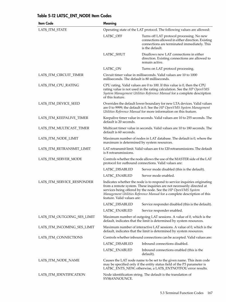
Table 5-12 LAT$C_ENT_NODE Item Codes
MeaningItem Code
Operating state of the LAT protocol. The following values are allowed:LAT$_ITM_STATE
Turns off LAT protocol processing. No newconnections allowed in either direction. Existingconnections are terminated immediately. Thisis the default.
LAT$C_OFF
Disallows new LAT connections in eitherdirection. Existing connections are allowed toremain active.
LAT$C_SHUT
Turns on LAT protocol processing.LAT$C_ON
Circuit timer value in milliseconds. Valid values are 10 to 1000milliseconds. The default is 80 milliseconds.
LAT$_ITM_CIRCUIT_TIMER
CPU rating. Valid values are 0 to 100. If this value is 0, then the CPUrating value is not used in the rating calculation. See the HP OpenVMSSystem Management Utilities Reference Manual for a complete descriptionof this feature.
LAT$_ITM_CPU_RATING
Overrides the default lower boundary for new LTA devices. Valid valuesare 0 to 9999; the default is 0. See the HP OpenVMS System ManagementUtilities Reference Manual for more information on this feature.
LAT$_ITM_DEVICE_SEED
Keepalive timer value in seconds. Valid values are 10 to 255 seconds. Thedefault is 20 seconds.
LAT$_ITM_KEEPALIVE_TIMER
Multicast timer value in seconds. Valid values are 10 to 180 seconds. Thedefault is 60 seconds.
LAT$_ITM_MULTICAST_TIMER
Maximum number of nodes in LAT database. The default is 0, where themaximum is determined by system resources.
LAT$_ITM_NODE_LIMIT
LAT retransmit limit. Valid values are 4 to 120 retransmissions. The defaultis 8 retransmissions.
LAT$_ITM_RETRANSMIT_LIMIT
Controls whether the node allows the use of the MASTER side of the LATprotocol for outbound connections. Valid values are:
LAT$_ITM_SERVER_MODE
Server mode disabled (this is the default).LAT$C_DISABLED
Server mode enabled.LAT$C_ENABLED
Indicates whether the node is to respond to service inquiries originatingfrom a remote system. These inquiries are not necessarily directed atservices being offered by the node. See the HP OpenVMS SystemManagement Utilities Reference Manual for a complete description of thisfeature. Valid values are:
LAT$_ITM_SERVICE_RESPONDER
Service responder disabled (this is the default).LAT$C_DISABLED
Service responder enabled.LAT$C_ENABLED
Maximum number of outgoing LAT sessions. A value of 0, which is thedefault, indicates that the limit is determined by system resources.
LAT$_ITM_OUTGOING_SES_LIMIT
Maximum number of interactive LAT sessions. A value of 0, which is thedefault, indicates that the limit is determined by system resources.
LAT$_ITM_INCOMING_SES_LIMIT
Controls whether inbound connections can be accepted. Valid values are:LAT$_ITM_CONNECTIONS
Inbound connections disabled.LAT$C_DISABLED
Inbound connections enabled (this is thedefault).
LAT$C_ENABLED
Causes the LAT node name to be set to the given name. This item codemay be specified only if the entity status field of the P3 parameter isLAT$C_ENTS_NEW; otherwise, a LAT$_ENTNOTFOU error results.
LAT$_ITM_NODE_NAME
Node identification string. The default is the translation ofSYS$ANNOUNCE.
LAT$_ITM_IDENTIFICATION
5.3 Terminal Function Codes 167

Table 5-12 LAT$C_ENT_NODE Item Codes (continued)
MeaningItem Code
Specifies a default service group code bit mask. This mask is then usedwhen creating new local services. The default is group code 0 enabledand all others disabled when the LAT software is initialized.Note that the use of the LAT$V_CLEAR bit is an exception for thisparameter code. If you clear bit LAT$V_CLEAR, group codescorresponding to the group code mask, as specified in the itemlist, areset. Alternatively, if you set LAT$V_CLEAR, group codes correspondingto the group code mask, as specified in the itemlist, are cleared.
LAT$_ITM_SERVICE_GROUPS
LAT group codes to be used when attempting outbound connectionsusing the MASTER side of the LAT protocol. The default is all groupcodes disabled when the LAT software is initialized.Note that the use of the LAT$V_CLEAR bit is an exception for thisparameter code. If you clear bit LAT$V_CLEAR, group codescorresponding to the group code mask, as specified in the itemlist, areset. Alternatively, if you set LAT$V_CLEAR, group codes correspondingto the group code mask, as specified in the itemlist, are cleared.
LAT$_ITM_USER_GROUPS
Node counters block. Allows for zeroing of all node counters. This itemcode may be specified only if the entity status field of the P3 parameteris LAT$C_ENTS_OLD and the LAT$V_CLEAR bit is set. Violating eitherof these two rules results in a returned status of SS$_BADPARAM.
LAT$_ITM_COUNTERS
Maximum unit number. Sets the highest value for a LTA unit number.Must be between 1 and 9999; defaults to 9999.
LAT$_ITM_MAXIMUM_UNITS
Indicates the highest number the resource attained since the host wasinitialized for LAT connections to node.
LAT$_ITM_HI_CIRCUITS1
Indicates current count of active connections to node.LAT$_ITM_CUR_CIRCUITS1
Indicates maximum allowed virtual circuits to node.LAT$_ITM_MAX_CIRCUITS1
Indicates highest number the resource attained since the host wasinitialized for LAT sessions.
LAT$_ITM_HI_SESSIONS1
Indicates current number of active sessions.LAT$_ITM_CUR_SESSIONS1
Indicates maximum possible sessions.LAT$_ITM_MAX_SESSIONS1
Indicates highest number the resource attained since the host wasinitialized of outgoing queued connect requests.
LAT$_ITM_HI_OUT_QUEUE1
Indicates current count of outgoing queued connect requests.LAT$_ITM_CUR_OUT_QUEUE1
Indicates maximum number of simultaneous outgoing queued connectrequests.
LAT$_ITM_MAX_OUT_QUEUE1
Indicates highest number the resource attained since the host wasinitialized of incoming queued requests.
LAT$_TIM_HI_IN_QUEUE1
Indicates current number of entries in the incoming connect queue.LAT$_ITM_CUR_IN_QUEUE1
Indicates maximum number of entries allowed on the incoming connectqueue.
LAT$_ITM_CUR_IN_QUEUE1
Indicates highest number the resource attained since the host wasinitialized of outstanding, unprocessed service announcement messagesby LATACP.
LAT$_ITM_HI_SAMS_QUEUED1
Indicates current number of outstanding, unprocessed serviceannouncement messages on LATACP's queue.
LAT$_ITM_CUR_SAMS_QUEUED1
Indicates maximum number of outstanding, unprocessed serviceannouncement messages allowed on LATACP's queue. If this limit is everreached, subsequent service announcement messages are not deliveredor processed by LATACP.
LAT$_ITM_MAX_SAMS_QUEUED1
Indicates highest number the resource attained since the host wasinitialized of outstanding, unprocessed solicit information messages byLATACP.
LAT$_ITM_HI_SOL_QUEUED1
168 Terminal Driver

Table 5-12 LAT$C_ENT_NODE Item Codes (continued)
MeaningItem Code
Indicates current number of outstanding, unprocessed solicit informationmessages on LATACP's queue.
LAT$_ITM_CUR_SOL_QUEUED
Indicates maximum number of outstanding, unprocessed solicitinformation messages allowed on LATACP's queue. If this limit is everreached, subsequent solicit information messages are not delivered orprocessed by LATACP.
LAT$_ITM_MAX_SOL_QUEUED1
Indicates highest number the resource attained since the host wasinitialized by the number of available services in LATACP database.
LAT$_ITM_HI_AVAIL_SVCS1
Indicates count of currently available LAT services in LATACP database.LAT$_ITM_CUR_AVAIL_SVCS1
Indicates maximum number of available services possible in LATACPdatabase.
LAT$_ITM_MAX_AVAIL_SVCS1
Indicates highest number the resource attained since the host wasinitialized of reachable nodes in LATACP database.
LAT$_ITM_HI_REACH_NODES1
Indicates current number of reachable nodes in LATACP database.LAT$_ITM_CUR_REACH_NODES1
Indicates maximum number of nodes allowed in LATACP database.LAT$_ITM_MAX_REACH_NODES1
Indicates highest number the resource attained since the host wasinitialized of locally offered services.
LAT$_ITM_HI_LCL_SVCS
Indicates current count of locally offered service.LAT$_ITM_CUR_LCL_SVCS1
Indicates maximum number of locally offered services.LAT$_ITM_MAX_LCL_SVCS1
Indicates number of discarded service announcement messages.LAT$_ITM_DISCARDED_NODES1
Indicates returned service class bit mask for supported service classes onnode. It is returned for both local and remote nodes. If service class 1 isenabled, then bit 1 is set in this mask. When bit setting equals 1, thisindicates the corresponding service class for that bit is enabled. That is,when bit 3 equal 1, then service class 3 is enabled.
LAT$_ITM_SERVICE_CLASSES1
Indicates in Boolean logic whether or not the LAT software is using largepacket support by default.
LAT$_ITM_LARGE_BUFFERS
Indicates in Boolean logic whether or not the LAT software is transmittingLAT service advertisement messages.
LAT$_ITM_ANNOUNCEMENTS
1 Alpha and Integrity servers specific
Table 5-13 lists the item codes that may be set for the LAT$C_ENT_SERVICE entity type.
Table 5-13 LAT$C_ENT_SERVICE Item Codes
MeaningItem Code
Static LAT service rating. The default is the dynamic rating calculation. Staticratings can be between 0 and 255.
LAT$_ITM_RATING
Service identification string. The default is the translation ofSYS$ANNOUNCE.
LAT$_IETEM_IDENTIFICATION
Defines the type of service. Valid values are:LAT$_ITM_SERVICE_TYPE
Creates a general timesharing service.LAT$C_ST_GENERAL
Creates a special application service thatmust then be associated with portsdedicated to accepting connections to thisservice (dedicated ports).
LAT$C_ST_APPLICATION
Indicates that the service is limited.LAT$C_ST_LIMITED1
Service counters block. Allows for zeroing of all service counters. This itemcode may be specified only if the entity status field is LAT$C_ENTS_OLDand the LAT$V_CLEAR bit is set. Violating either of these two rules resultsin a returned status of SS$_BADPARAM.
LAT$_ITM_COUNTERS
5.3 Terminal Function Codes 169

Table 5-13 LAT$C_ENT_SERVICE Item Codes (continued)
MeaningItem Code
Indicates that if a value of LAT$C_ENABLED is indicated, then the serviceis password protected. Indicates that if a value of LAT$C_DISABLED isindicated, then the service is not password protected.
LAT$_ITM_PASSWORD1
Indicates a subblock contained in an itemlist, which has a list of limited portsassociated with the named service. This subblock may be repeated severaltimes; that is, once for each limited LAT device associated with the specifiedservice.
LAT$_ITM_LIM_PORT_BLOCK1
1 Alpha and Integrity servers specific
Table 5-14 lists the item codes that may be set for the LAT$C_ENT_LINK entity type.
Table 5-14 LAT$C_ENT_LINK Item Codes
MeaningItem Code
Operating state of the LAT protocol. Valid values are:LAT$_ITM_STATE
Turns off LAT protocol processing. No newconnections allowed in either direction. Existingconnections are terminated immediately.
LAT$C_OFF
Disallows new LAT connections in either direction.Existing connections are allowed to remain active.
LAT$C_SHUT
Turns on LAT protocol processing. This is thedefault.
LAT$C_ON
The name of the local area network (LAN) device to be used for this link.The default is hardware-dependent.
LAT$_ITM_DEVICE_NAME
Specifies whether to use the DECnet address when starting the LAT protocolon the LAN controller associated with this link. Valid values are:
LAT$_ITM_DECNET_ADDRESS
DECnet address use disabled.LAT$C_DISABLED
DECnet address use enabled (this is the default).LAT$C_ENABLED
Link counters block. Allows for zeroing of all link counters. This item codemay be specified only if the entity status field is LAT$C_ENTS_OLD andthe LAT$V_CLEAR bit is set. Violating either of these two rules results in areturned status of SS$_BADPARAM.
LAT$_ITM_COUNTERS
Table 5-15 lists the item codes that may be set for the LAT$C_ENT_PORT entity type.
Table 5-15 LAT$C_ENT_PORT Item Codes
MeaningItem Code
Type of port. Valid values are:LAT$_ITM_PORT_TYPE
Application port for solicitedconnections.
LAT$C_PT_APPLICATION
Dedicated port associatedwith a local applicationservice.
LAT$C_PT_DEDICATED
Indicates that the port typeis limited.
LAT$C_PT_LIMITED1
Controls whether the solicited connection requests queued ornonqueued access. Valid values are:
LAT$_ITM_QUEUED
Queued access disabled.LAT$C_DISABLED
170 Terminal Driver

Table 5-15 LAT$C_ENT_PORT Item Codes (continued)
MeaningItem Code
Queued access enabled (thisis the default).
LAT$C_ENABLED
Controls the class driver that the LAT driver communicates withwhen a connection is established. This item code can be used onlywith an entity status of LAT$C_ENTS_NEW. Therefore, the serviceclass must be specified when the device is created. An attempt tochange the service class of an existing device returnsSS$_BADPARAM. Valid values are:
LAT$_ITM_SERVICE_CLASS
Service class 1, TTDRIVER(this is the default).
LAT$C_SERVCLASS_INTERACTIVE
Service class 3, X Protocol.LAT$C_SERVCLASS_XTRANSPORT
Service class 4, X fonts.LAT$C_SERVCLASS_FONT
For X devices, this is the binary value of the display number, whichmay need to be transmitted in some LAT messages. Values rangefrom 0--255, with a default of 0. This item code has meaning onlywhen used with service classes 3 and 4(LAT$C_SERVCLASS_XTRANSPORT ANDLAT$C_SERVCLASS_FONT).
LAT$_ITM_DISPLAY_NUMBER
Target node name for connection. This parameter must be specifiedfor application ports and may optionally be specified for forwardports.
LAT$_ITM_TARGET_NODE_NAME
Target service name for connection. This parameter must be specifiedfor forward ports and may optionally be specified for applicationports. For dedicated ports, this parameter specifies the localapplication service to which the port should be associated.
LAT$_ITM_TARGET_SERVICE_NAME
Target port name for connection. This parameter may optionally bespecified for application ports or forward ports; it is ignored for allother kinds of ports.
LAT$_ITM_TARGET_PORT_NAME
Password string for remote service on forward ports. This parametermust be specified to access services that are protected with apassword. This parameter is ignored if it is specified for a service thatis not protected with a password.
LAT$_ITM_SERVICE_PASSWORD
Indicates if an LAT device tells a remote node that the connection iscoming from a dialing source. Possible values are LAT$C_ENABLEDor LAT$C_DISABLED.
LAT$_ITM_DIALUP1
Indicates if a connect request has autoprompt enabled. Possible valuesare LAT$C_ENABLED or LAT$C_DISABLED.
LAT$_ITM_AUTOPROMPT1
1 Alpha and Integrity servers specific.
5.3.4.4 Obtaining Information About LAT EntitiesThe LAT SENSEMODE $QIO function (IO$_TTY_PORT!IO$M_LT_SENSEMODE) is used toobtain information about LAT nodes, services, ports, and links.The LAT SENSEMODE $QIO function accepts four arguments: P1, P2, P3, and P4. P1 is theaddress of a buffer into which information about the desired entity is returned. The informationis returned in the form of an item list. Unlike system services such as $GETDVI or $GETJPI, youdo not select which items of information are returned. P2 is the length of the buffer specified inP1, in bytes. The number of bytes of information returned in the P1 buffer is returned in IOSB+2.
5.3 Terminal Function Codes 171

P3 specifies the type of entity to which the SENSEMODE operation applies. The entity type canbe one of five types:• Node (LAT$C_ENT_NODE). Node, including the local node.• Service (LAT$C_ENT_SERVICE). Service, including local services.• Link (LAT$C_ENT_LINK). Data link associated with the LAN.• Port (LAT$C_ENT_PORT).• Queue Entry (LAT$C_ENT_QUEUE_ENTRY). Indicates queue entry entities.The value for the entity type occupies the low-order 16 bits (bits 0--15) of the P3 parameter. Bits16--23 are used as a flag field. Two bits are currently defined within this field:LAT$V_SENSE_NEXT and LAT$V_SENSE_FULL. If the LAT$V_SENSE_NEXT bit is 0,information about the current entity described by the P3 and P4 parameters is returned to theuser; if this bit is 1, information about the next entity that logically follows the one described byP4 is returned. If LAT$V_SENSE_FULL is 0, only those item codes marked SUMMARY in thefollowing tables are returned; if this bit is 1, all item codes that describe the entity specified bythe P3 and P4 parameters are returned.P4 may contain the address of an entity name string descriptor. If this parameter is omitted(contains a zero or the address of a descriptor that points to an empty string) and theLAT$V_SENSE_NEXT bit is set, information about the first entity that matches the entity typesupplied by P3 is returned.If P4 is omitted and the LAT$V_SENSE_NEXT bit is 0, a default entity name may be used insome cases. The defaults for each entity type are as follows:• LAT$C_ENT_NODE—The local node.• LAT$C_ENT_SERVICE—No default; you must specify the service name.• LAT$C_ENT_LINK—The string LAT$LINK.• LAT$C_ENT_PORT—The device name associated with the currently assigned channel (the
CHAN parameter of the $QIO function.)SENSEMODE can return the following failure return codes:• SS$_NOPRIV—No privilege to complete the desired operation• SS$_ACCVIO—Part of the argument list or item list is not addressable
5.3.4.4.1 SENSEMODE Item Codes
Each item in the itemlist starts with a one-word (16-bit) item code that describes the type ofinformation contained in the item. The item code is followed by a value associated with the item.Item codes in which the bit named LAT$V_STRING is 0 take a longword value. The associatedvalue is contained in the longword immediately following the item code in the itemlist. Itemcodes in which this bit is 1 take a counted string for their value. The byte immediately followingthe item code contains a byte count, which describes the length of the string that immediatelyfollows it.Table 5-16 lists the item codes that are returned for the LAT$C_ENT_NODE entity type. Itemcodes noted as LOCAL are returned only if the information being returned is for the local node.Item codes noted as REMOTE are returned only if the information being returned is for a remotenode. Item codes noted as BOTH are returned for both types of nodes.
Table 5-16 LAT$C_ENT_NODE Item Codes
MeaningItem Code
LAT node name for the node.LAT$_ITM_NODE_NAME (BOTH,SUMMARY)
Node identification string.LAT$_ITM_IDENTIFICATION (BOTH,SUMMARY)
172 Terminal Driver

Table 5-16 LAT$C_ENT_NODE Item Codes (continued)
MeaningItem Code
Type of node. Possible values are:LAT$_ITM_NODE_TYPE (BOTH,SUMMARY)
Node is local node.LAT$C_NT_LOCAL
Node is remote node.LAT$C_NT_REMOTE
Operating state of the LAT protocol. Possible values are:LAT$_ITM_STATE (LOCAL,SUMMARY)
New connections are allowed and theLAT protocol is running.
LAT$C_ON
New connections are not allowed. TheLAT protocol is not running.
LAT$C_OFF
No new connections are allowed.Currently active connections are stillmaintained. The LAT protocol remainsrunning only until the last active sessionis disconnected, at which time the nodeis placed in the OFF state.
Current status of remote node. This item code is present only if a LATvirtual circuit does not currently exist between the local node and thisremote node. Possible values are:
LAT$_ITM_NODE_STATUS (REMOTE,SUMMARY)
Remote node is reachable.LAT$C_REACHABLE
Remote node is unreachable.LAT$C_UNREACHABLE
Remote node status is unknown.LAT$C_UNKNOWN
Number of LAT sessions from the local node to this remote node. Thisitem code replaces the LAT$_ITM_NODE_STATUS item code for remotenodes to which a LAT virtual circuit currently exists.
LAT$_ITM_CONNECTED_COUNT(REMOTE, SUMMARY)
A bit mask of LAT group codes that are serviced by the node.LAT$_ITM_SERVICE_GROUPS (BOTH)
LAT protocol version string.LAT$_ITM_PROTOCOL_VERSION(BOTH)
LAN address used by the node.LAT$_ITM_DATALINK_ADDRESS (REMOTE)
Maximum number of nodes in LAT database. The default is 0, where themaximum is determined by system resources.
LAT$_ITM_NODE_LIMIT
LAT retransmit limit. Possible values are 4 to 120 retransmissions. Thedefault is 8 retransmissions.
LAT$_ITM_RETRANSMIT_LIMIT
Maximum LTA unit number.LAT$_ITM_MAXIMUM_UNITS (LOCAL)
Controls whether the node allows the use of the MASTER side of theLAT protocol for outbound connections. Possible values are:
LAT$_ITM_SERVER_MODE (LOCAL)
Server mode disabled (this is the default).LAT$C_DISABLED
Server mode enabled.LAT$C_ENABLED
Indicates whether the node is to respond to service inquiries originatingfrom a remote system. These inquiries are not necessarily directed atservices being offered by the node. See the HP OpenVMS SystemManagementUtilities ReferenceManual for more information on this feature.Possible values are:
LAT$_ITM_SERVICE_RESPONDER(LOCAL)
Service responder disabled (this is thedefault).
LAT$C_DISABLED
5.3 Terminal Function Codes 173
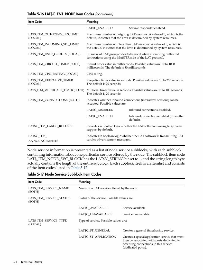
Table 5-16 LAT$C_ENT_NODE Item Codes (continued)
MeaningItem Code
Service responder enabled.LAT$C_ENABLED
Maximum number of outgoing LAT sessions. A value of 0, which is thedefault, indicates that the limit is determined by system resources.
LAT$_ITM_OUTGOING_SES_LIMIT(LOCAL)
Maximum number of interactive LAT sessions. A value of 0, which isthe default, indicates that the limit is determined by system resources.
LAT$_ITM_INCOMING_SES_LIMIT(LOCAL)
Bit mask of LAT group codes to be used when attempting outboundconnections using the MASTER side of the LAT protocol.
LAT$_ITM_USER_GROUPS (LOCAL)
Circuit timer value in milliseconds. Possible values are 10 to 1000milliseconds. The default is 80 milliseconds.
LAT$_ITM_CIRCUIT_TIMER (BOTH)
CPU rating.LAT$_ITM_CPU_RATING (LOCAL)
Keepalive timer value in seconds. Possible values are 10 to 255 seconds.The default is 20 seconds.
LAT$_ITM_KEEPALIVE_TIMER(LOCAL)
Multicast timer value in seconds. Possible values are 10 to 180 seconds.The default is 20 seconds.
LAT$_ITM_MULTICAST_TIMER (BOTH)
Indicates whether inbound connections (interactive sessions) can beaccepted. Possible values are:
LAT$_ITM_CONNECTIONS (BOTH)
Inbound connections disabled.LAT$C_DISABLED
Inbound connections enabled (this is thedefault).
LAT$C_ENABLED
Indicates in Boolean logic whether the LAT software is using large packetsupport by default.
LAT$C_ITM_LARGE_BUFFERS
Indicates in Boolean logic whether the LAT software is transmitting LATservice advertisement messages.
LAT$C_ITM_ANNOUNCEMENTS
Node service information is presented as a list of node service subblocks, with each subblockcontaining information about one particular service offered by the node. The subblock item codeLAT$_ITM_NODE_SVC_BLOCK has the LAT$V_STRING bit set to 1, and the string length byteactually contains the length of the entire subblock. Each subblock itself is an itemlist and consistsof the item codes listed in Table 5-17.
Table 5-17 Node Service Subblock Item Codes
MeaningItem Code
Name of a LAT service offered by the node.LAT$_ITM_SERVICE_NAME(BOTH)
Status of the service. Possible values are:LAT$_ITM_SERVICE_STATUS(BOTH)
Service available.LAT$C_AVAILABLE
Service unavailable.LAT$C_UNAVAILABLE
Type of service. Possible values are:LAT$_ITM_SERVICE_TYPE(LOCAL)
Creates a general timesharing service.LAT$C_ST_GENERAL
Creates a special application service that mustthen be associated with ports dedicated toaccepting connections to this service(dedicated ports).
LAT$C_ST_APPLICATION
174 Terminal Driver
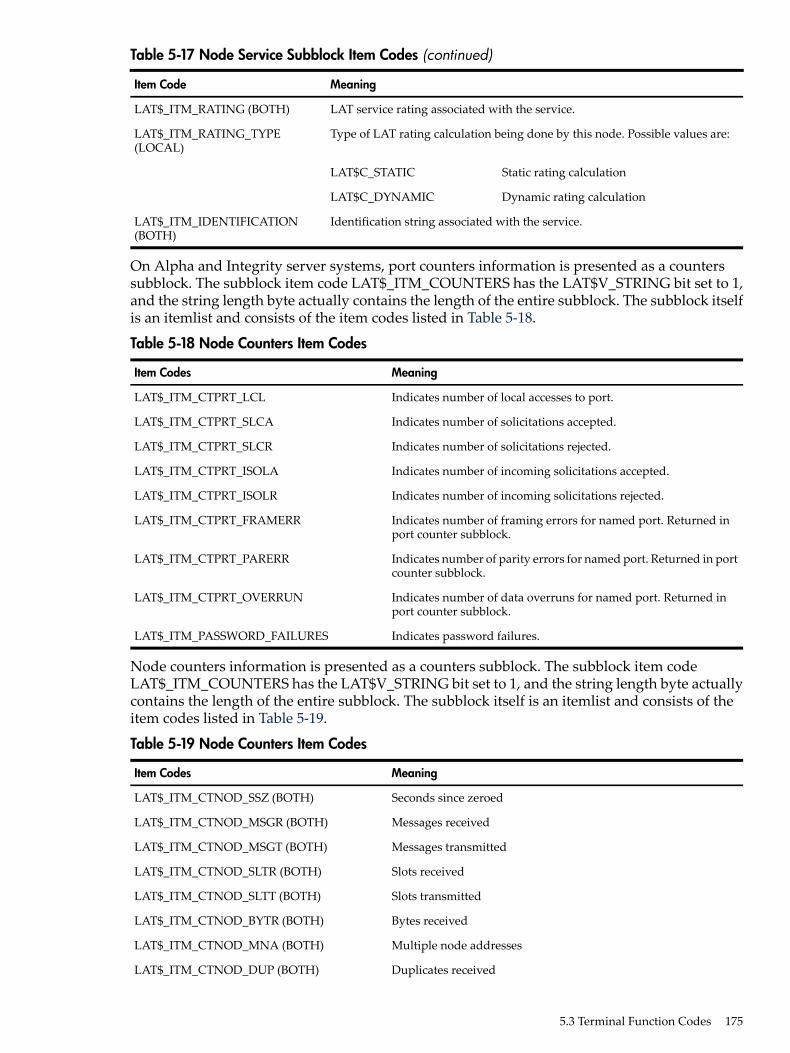
Table 5-17 Node Service Subblock Item Codes (continued)
MeaningItem Code
LAT service rating associated with the service.LAT$_ITM_RATING (BOTH)
Type of LAT rating calculation being done by this node. Possible values are:LAT$_ITM_RATING_TYPE(LOCAL)
Static rating calculationLAT$C_STATIC
Dynamic rating calculationLAT$C_DYNAMIC
Identification string associated with the service.LAT$_ITM_IDENTIFICATION(BOTH)
On Alpha and Integrity server systems, port counters information is presented as a counterssubblock. The subblock item code LAT$_ITM_COUNTERS has the LAT$V_STRING bit set to 1,and the string length byte actually contains the length of the entire subblock. The subblock itselfis an itemlist and consists of the item codes listed in Table 5-18.
Table 5-18 Node Counters Item Codes
MeaningItem Codes
Indicates number of local accesses to port.LAT$_ITM_CTPRT_LCL
Indicates number of solicitations accepted.LAT$_ITM_CTPRT_SLCA
Indicates number of solicitations rejected.LAT$_ITM_CTPRT_SLCR
Indicates number of incoming solicitations accepted.LAT$_ITM_CTPRT_ISOLA
Indicates number of incoming solicitations rejected.LAT$_ITM_CTPRT_ISOLR
Indicates number of framing errors for named port. Returned inport counter subblock.
LAT$_ITM_CTPRT_FRAMERR
Indicates number of parity errors for named port. Returned in portcounter subblock.
LAT$_ITM_CTPRT_PARERR
Indicates number of data overruns for named port. Returned inport counter subblock.
LAT$_ITM_CTPRT_OVERRUN
Indicates password failures.LAT$_ITM_PASSWORD_FAILURES
Node counters information is presented as a counters subblock. The subblock item codeLAT$_ITM_COUNTERS has the LAT$V_STRING bit set to 1, and the string length byte actuallycontains the length of the entire subblock. The subblock itself is an itemlist and consists of theitem codes listed in Table 5-19.
Table 5-19 Node Counters Item Codes
MeaningItem Codes
Seconds since zeroedLAT$_ITM_CTNOD_SSZ (BOTH)
Messages receivedLAT$_ITM_CTNOD_MSGR (BOTH)
Messages transmittedLAT$_ITM_CTNOD_MSGT (BOTH)
Slots receivedLAT$_ITM_CTNOD_SLTR (BOTH)
Slots transmittedLAT$_ITM_CTNOD_SLTT (BOTH)
Bytes receivedLAT$_ITM_CTNOD_BYTR (BOTH)
Multiple node addressesLAT$_ITM_CTNOD_MNA (BOTH)
Duplicates receivedLAT$_ITM_CTNOD_DUP (BOTH)
5.3 Terminal Function Codes 175

Table 5-19 Node Counters Item Codes (continued)
MeaningItem Codes
Messages retransmittedLAT$_ITM_CTNOD_MRT (BOTH)
Illegal messages receivedLAT$_ITM_CTNOD_ILM (BOTH)
Illegal slots receivedLAT$_ITM_CTNOD_ILS (BOTH)
Solicitations acceptedLAT$_ITM_CTNOD_SLCA (BOTH)
Solicitations rejectedLAT$_ITM_CTNOD_SLCR (BOTH)
Transmit errorsLAT$_ITM_CTNOD_TER (LOCAL)
Resource errorsLAT$_ITM_CTNOD_RES (LOCAL)
No transmit bufferLAT$_ITM_CTNOD_NTB (LOCAL)
Virtual circuit timeoutLAT$_ITM_CTNOD_TMO (LOCAL)
Discarded output bytesLAT$_ITM_CTNOD_DOB (LOCAL)
Last transmit errorLAT$_ITM_CTNOD_LSTER (LOCAL)
Number of multicast bytes transmittedLAT$_ITM_CTNOD_MCBXMT (LOCAL)
Number of multicast bytes receivedLAT$_ITM_CTNOD_MCBRCV (LOCAL)
Number of multicast messages transmittedLAT$_ITM_CTNOD_MCMXMT (LOCAL)
Number of multicast messages receivedLAT$_ITM_CTNOD_MCMRCV (LOCAL)
Number of solicitation failuresLAT$_ITM_CTNOD_SOLFAIL (LOCAL)
Number of times attention slot data was lostLAT$_ITM_CTNOD_ATLOS (LOCAL)
Number of times user data was lostLAT$_ITM_CTNOD_DATLOS (LOCAL)
Number of times a reject slot could not be sentLAT$_ITM_CTNOD_NOREJ (LOCAL)
Number of times remote node counters were lostLAT$_ITM_CTNOD_LOSCT (LOCAL)
Number of service announcement messages lostLAT$_ITM_CTNOD_LOSSAM (LOCAL)
Number of times a service announcement message could not besent
LAT$_ITM_CTNOD_NOSAM (LOCAL)
Number of times node status was lostLAT$_ITM_CTNOD_NOSTS (LOCAL)
Number of times no link was available for a transmitLAT$_ITM_CTNOD_NOXMT (LOCAL)
Number of controller errorsLAT$_ITM_CTNOD_CTLERR (LOCAL)
Lost controller errorLAT$_ITM_CTNOD_CERRCOD (LOCAL)
Number of incoming solicitations acceptedLAT$_ITM_CTNOD_ISOLA (LOCAL)
Number of incoming solicitations rejectedLAT$_ITM_CTNOD_ISOLR (LOCAL)
Protocol error countLAT$_ITM_CTNOD_PROTO (LOCAL)
Indicates that the node attempted to start up too many LAT sessionsfor a specific virtual circuit
LAT$_ITM_CTNOD_XSTR (REMOTE)1
1 Alpha and Integrity servers specific.
Several protocol errors are also included in a separate subblock. The protocol errors item codeis LAT$_ITM_PROTOCOL_ERRORS and has LAT$V_STRING set (the size of the subblock iscontained in the first byte following the item code). The item codes and the events they representare listed in Table 5-20.
176 Terminal Driver

Table 5-20 Protocol Error Item Codes
MeaningItem Codes
Invalid message type received.LAT$_ITM_CTPRO_IVM (LOCAL)
Invalid start message received.LAT$_ITM_CTPRO_ISM (LOCAL)
Invalid sequence number received.LAT$_ITM_CTPRO_IVS (LOCAL)
Zero-node index received.LAT$_ITM_CTPRO_NIZ (LOCAL)
Node circuit index out of range.LAT$_ITM_CTPRO_ICI (LOCAL)
Node circuit sequence invalid.LAT$_ITM_CTPRO_CSI (LOCAL)
Node circuit index no longer valid.LAT$_ITM_CTPRO_NLV (LOCAL)
Circuit was forced to halt.LAT$_ITM_CTPRO_HALT (LOCAL)
Invalid master slot index.LAT$_ITM_CTPRO_MIZ (LOCAL)
Invalid slave slot index.LAT$_ITM_CTPRO_SIZ (LOCAL)
Invalid credit field.LAT$_ITM_CTPRO_CRED (LOCAL)
Repeat creation of slot by master.LAT$_ITM_CTPRO_RCSM (LOCAL)
Repeat disconnection of slot by master.LAT$_ITM_CTPRO_RDSM (LOCAL)
Indicates the number of times a LAT message was received with an invalidservice class specified in that message (local node only).
LAT$_ITM_CTPRO_INVCLASS(LOCAL)
Indicates that a remote node attempted to start up too many LAT sessions.When a virtual circuit is started between two LAT nodes, the maximumnumber of sessions on that virtual circuit is negotiated. If the master nodeattempts to create more sessions than the maximum number of sessionson a virtual circuit, then the operating system rejects the excess connectionsand increments this counter.
LAT$_ITM_CTPRO_EXCSTART(LOCAL)1
1 Alpha and Integrity servers specific.
Table 5-21 lists the item codes that are returned for the LAT$C_ENT_SERVICE entity type. Asin Table 5-16, item codes noted as LOCAL are returned only if the information being returnedis for a locally offered service. Item codes noted as REMOTE are returned only if the informationbeing returned is for a service offered by a remote node. Item codes noted as BOTH are returnedfor both types of services.
Table 5-21 LAT$C_ENT_SERVICE Item Codes
MeaningItem Code
Service name.LAT$_ITM_SERVICE_NAME(BOTH, SUMMARY)
Status of the specified service. Possible values are:LAT$_ITM_SERVICE_STATUS(BOTH, SUMMARY)
Service available.LAT$C_AVAILABLE
Service unavailable.LAT$C_UNAVAILABLE
Type of service. Possiblevalues are:
LAT$_ITM_SERVICE_TYPE(LOCAL,SUMMARY)
General timesharing service.LAT$C_ST_GENERAL
5.3 Terminal Function Codes 177

Table 5-21 LAT$C_ENT_SERVICE Item Codes (continued)
MeaningItem Code
Special application service associated withports dedicated to accepting connections to thisservice.
LAT$C_ST_APPLICATION
Service identification string, as advertised by the highest rated node thatcurrently offers the service.
LAT$_ITM_IDENTIFICATION(BOTH, SUMMARY)
Service node information is presented as a list of service node subblocks, with each subblockcontaining information about one particular node that offers the service. The subblock item codeLAT$_ITM_SVC_NODE_BLOCK has the LAT$V_STRING bit set to 1, and the string length byteactually contains the length of the entire subblock. Each subblock itself is an itemlist and consistsof the item codes listed in Table 5-22.
Table 5-22 Service Node Subblock Item Codes
MeaningItem Code
Name of a LAT node that offers the selected service.LAT$C_ITM_NODE_NAME (BOTH)
Current state of the LAT protocol on the local node. Possible values are:LAT$_ITM_STATE (LOCAL)
New connections are allowed, and the LATprotocol is running.
LAT$C_ON
New connections are not allowed, and anycurrent connections are abnormallyterminated. The LAT protocol is not running.
LAT$C_OFF
No new connections are allowed. Currentlyactive connections are still maintained. TheLAT protocol remains running only until thelast active sessions is disconnected, at whichtime the node is placed in the OFF state.
LAT$C_SHUT
Current status of the remote node. This item code is present only if a LATvirtual circuit does not currently exist to the remote node. Possible valuesare:
LAT$_ITM_NODE_STATUS (REMOTE)
Remote node is reachable.LAT$C_REACHABLE
Remote node is unreachable.LAT$C_UNREACHABLE
Remote node status is unknown.LAT$C_UNKNOWN
Number of LAT sessions from the local node to this remote node. This itemcode replaces the LAT$_ITM_NODE_STATUS item code for remote nodesto which a LAT virtual circuit currently exists.
LAT$_ITM_CONNECTED_COUNT(REMOTE)
LAT service rating associated with the service.LAT$_ITM_RATING (BOTH)
Type of LAT rating calculation being done by this node. Possible valuesare LAT$C_STATIC and LAT$C_DYNAMIC.
LAT$_ITM_RATING_TYPE (LOCAL)
Identification string associated with the service.LAT$_ITM_IDENTIFICATION (BOTH)
Service counters information is presented as a counters subblock. The subblock item codeLAT$_ITM_COUNTERS has the LAT$V_STRING bit set, and the string length byte actuallycontains the length of the entire subblock. Each subblock itself is an itemlist and consists of theitem codes listed in Table 5-23.
178 Terminal Driver

Table 5-23 Service Counters Subblock Item Codes
MeaningItem Codes
Seconds since zeroed.LAT$_ITM_CTSRV_SSZ (BOTH)
Outgoing connections attempted (the number of times the local node hasattempted to connect to the service offered on a remote node).Outgoing connections completed (the number of times the local nodesuccessfully connected to the service offered on a remote node).
LAT$_ITM_CTSRV_MCNA (BOTH)
LAT$_ITM_CTSRV_MCNC (BOTH)
Incoming connections accepted (the number of times the local node has accepteda connection request from a remote node to the locally offered service).
LAT$_ITM_CTSRV_SCNA (BOTH)
Incoming connections rejected (the number of times the local node rejected aconnection request from a remote node to the locally offered service).
LAT$_ITM_CTSRV_SCNR (BOTH)
If the selected service is an application service offered by the local node, a listof one or more port subblocks is included in the itemlist. These subblocksdescribe the dedicated port or ports associated with this application service,with each subblock describing one particular port. The subblock item codeLAT$_ITM_DED_PORT_BLOCK has the LAT$V_STRING bit set, and the stringlength byte actually contains the length of the entire subblock. Each subblockitself is an itemlist and currently consists only of the following item code:
LAT$_ITM_DED_PORT_BLOCK(LOCAL)
Name of the dedicated port.LAT$_ITM_PORT_NAME(LOCAL)
Indicates password failures.LAT$_ITM_PASSWORD_FAILURE
Table 5-24 lists the item codes that are returned for the LAT$C_ENT_LINK entity type.
Table 5-24 LAT$C_ENT_LINK Item Codes
MeaningItem Codes
Link name (such as LAT$LINK).LAT$_ITM_LINK_NAME (SUMMARY)
State of the link. Possible values are:LAT$_ITM_STATE (SUMMARY)
New connections are allowed, and the LATprotocol is running.
LAT$C_ON
New connections are not allowed, and any currentconnections are abnormally terminated. The LATprotocol is not running.
LAT$C_OFF
No new connections are allowed. Currently activeconnections are still maintained. The LAT protocolremains running only until the last active sessionis disconnected, at which time the node is placedin the OFF state.
LAT$C_SHUT
The name of the LAN device used for the link.LAT$_ITM_DEVICE_NAME(SUMMARY)
The LAN device's current physical address for the link.LAT$_ITM_DATALINK_ADDRESS
Indicates whether the link attempts to use the default DECnet LAN addresswhen starting the data link controller (enabling the LAT protocol). Possiblevalues are:
LAT$_ITM_DECNET_ADDRESS
DECnet LAN address use disabled.LAT$C_DISABLED
DECnet LAN address use enabled (this is thedefault.
LAT$C_ENABLED
Link counters information is presented as a counters subblock. The subblock item codeLAT$_ITM_COUNTERS has the LAT$V_STRING bit set, and the string length byte actually
5.3 Terminal Function Codes 179
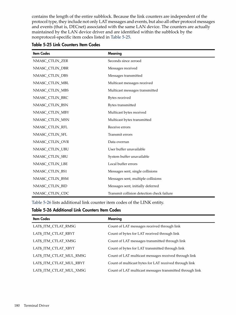
contains the length of the entire subblock. Because the link counters are independent of theprotocol type, they include not only LAT messages and events, but also all other protocol messagesand events (that is, DECnet) associated with the same LAN device. The counters are actuallymaintained by the LAN device driver and are identified within the subblock by thenonprotocol-specific item codes listed in Table 5-25.
Table 5-25 Link Counters Item Codes
MeaningItem Codes
Seconds since zeroedNMA$C_CTLIN_ZER
Messages receivedNMA$C_CTLIN_DBR
Messages transmittedNMA$C_CTLIN_DBS
Multicast messages receivedNMA$C_CTLIN_MBL
Multicast messages transmittedNMA$C_CTLIN_MBS
Bytes receivedNMA$C_CTLIN_BRC
Bytes transmittedNMA$C_CTLIN_BSN
Multicast bytes receivedNMA$C_CTLIN_MBY
Multicast bytes transmittedNMA$C_CTLIN_MSN
Receive errorsNMA$C_CTLIN_RFL
Transmit errorsNMA$C_CTLIN_SFL
Data overrunNMA$C_CTLIN_OVR
User buffer unavailableNMA$C_CTLIN_UBU
System buffer unavailableNMA$C_CTLIN_SBU
Local buffer errorsNMA$C_CTLIN_LBE
Messages sent, single collisionsNMA$C_CTLIN_BS1
Messages sent, multiple collisionsNMA$C_CTLIN_BSM
Messages sent, initially deferredNMA$C_CTLIN_BID
Transmit collision detection check failureNMA$C_CTLIN_CDC
Table 5-26 lists additional link counter item codes of the LINK entity.
Table 5-26 Additional Link Counters Item Codes
MeaningItem Codes
Count of LAT messages received through linkLAT$_ITM_CTLAT_RMSG
Count of bytes for LAT received through linkLAT$_ITM_CTLAT_RBYT
Count of LAT messages transmitted through linkLAT$_ITM_CTLAT_XMSG
Count of bytes for LAT transmitted through linkLAT$_ITM_CTLAT_XBYT
Count of LAT multicast messages received through linkLAT$_ITM_CTLAT_MUL_RMSG
Count of multicast bytes for LAT received through linkLAT$_ITM_CTLAT_MUL_RBYT
Count of LAT multicast messages transmitted through linkLAT$_ITM_CTLAT_MUL_XMSG
180 Terminal Driver

Table 5-26 Additional Link Counters Item Codes (continued)
MeaningItem Codes
Count of multicast bytes for LAT transmitted through linkLAT$_ITM_CTLAT_MUL_XBYT
This block contains the LAT-specific counters for the specified link.Counters returned in this block are the ones defined above (withCTLAT in their name). These counters are LAT-specific for the link(device). They do not include counts from other protocols using thesame adapter.
LAT$_ITM_LAT_DEV_CTR_BLOCK
The counter item codes listed in Table 5-26 are used by LATCP in the display generated by thecommand:$SHOW LINK /COUNTER
The display looks similar to the following:
Link Name: LAT$LINKDevice Name: _XQA1:
Seconds Since Zeroed: 65535Messages Received: 7080630 Messages Sent: 2135394LAT Messages Received: 1484817 LAT Messages Sent: 2086167Multicast Msgs Received: 5578139 Multicast Msgs Sent: 10775LAT Multicast Msgs Received: 5093417 LAT Multicast Msgs Sent: 9142Bytes Received: 678189475 Bytes Sent: 1312778402LAT Bytes Received: 107809441 LAT Bytes Sent: 1278118808Multicast Bytes Received: 602984574 Multicast Bytes Sent: 1696264LAT Multicast Bytes Received: 565264261 LAT Multicast Bytes Sent: 1448342System Buffer Unavailable: 1638401 User Buffer Unavailable: 1Unrecognized Destination: 65537 Data Overrun: 1Receive Errors: 7 Transmit Errors: 1
Receive Errors (bitmask = 001) - Transmit Errors (bitmask = 001) - Block Check Error: Yes Excessive Collisions: Yes Framing Error: No Carrier Check Failure: No Frame Too Long: No Short Circuit: No Frame Status Error: No Open Circuit: No Frame Length Error: No Frame Too Long: No Remote Failure To Defer: No Transmit Underrun: No Transmit Failure: No
CSMACD Specific Counters————————
Transmit CDC Failure: 1
Messages Transmitted - Single Collision: 5208 Multiple Collisions: 4732 Initially Deferred: 0
Table 5-27 lists the item codes that are returned for the LAT$C_ENT_PORT entity type.
Table 5-27 LAT$C_ENT_PORT Item Codes
MeaningItem Code
Name of the port (such as _LTA15:).LAT$_ITM_PORT_NAME_SUMMARY
Type of port.LAT$_ITM_PORT_TYPE_SUMMARY
Possible values are:
Forward port used for outgoing LAT connections or formanagement functions.
LAT$_PT_FORWARD
Interactive port created as the result of an incoming LATconnection request.
LAT$_PT_INTERACTIVE
Application port for solicited connections.LAT$_PT_APPLICATION
5.3 Terminal Function Codes 181

Table 5-27 LAT$C_ENT_PORT Item Codes (continued)
MeaningItem Code
Dedicated port associated with a local service.LAT$_PT_DEDICATED
Controls whether the solicited connection requests queuedor nonqueued access.
LAT$_ITM_QUEUED
Possible values are:
Queued access disabled.LAT$C_DISABLED
Queued access enabled (this is the default).LAT$C_ENABLED
Indicates the class driver with which the device iscommunicating. This item code can be used only with anentity status of LAT$C_ENTS_NEW. Therefore, the serviceclass must be specified when the device is created. An attemptto change the service class of an existing device returnsSS$_BADPARAM.
LAT$_ITM_SERVICE_CLASS
Possible values are:
Service class 1, TTDRIVER (this is the default).LAT$C_SERVCLASS_INTERACTIVE
Service class 2, TEST SERVICE.LAT$C_SERVCLASS_TESTSERVICE
Service class 3, X Protocol.LAT$C_SERVCLASS_XTRANSPORT
Service class 4, X fonts.LAT$C_SERVCLASS_FONT
Display number value for the device. This field has meaningfor services classes 3 and 4 (X) only. It returns a value of 0 forall other service classes.
LAT$_ITM_DISPLAY_NUMBER
Reason (if any) for the last disconnect on the port. If it is nota 0--19 LAT rejection code, it is a LAT message code. The 0--19LAT rejection code meanings are listed in Table 5-31.
LAT$_ITM_DISCONNECT_REASON
Name of service to which this port is connected. For forwardand application ports, this is the name of the remote serviceto which the port is connected (if any). For interactive anddedicated ports, this is the name of the local service thataccepted the remote-initiated connection.
LAT$C_PT_STATE_DISCONNECTING1
Name of remote node to which this port is connected.LAT$_ITM_CONNECTED_NODE_NAME1
Name of remote port to which this port is connected.LAT$_ITM_CONNECTED_PORT_NAME1
Name of the link on which the LAT connection exists.LAT$_ITM_CONNECTED_LINK_NAME1
Target service name for connection of forward or applicationports. For dedicated ports, this item code specifies the localservice with which the port is associated.
LAT$_ITM_TARGET_SERVICE_NAME2
Target node name for connection of forward or applicationports.
LAT$_ITM_TARGET_NODE_NAME2
Target port name for connection of forward or applicationports.
LAT$_ITM_TARGET_PORT_NAME2
Indicates current node queue position for connect request.Returned during SENSEMODE of port entity.
LAT$_ITM_NODE_QUEUE_POSITION3
Indicates current service queue position for connect request.Returned during SENSEMODE of port entity.
LAT$_ITM_SERVICE_QUEUE_POSITION3
Current port state.LAT$_ITM_PORT_STATE
Possible values are:
Port is inactive.LAT$C_PT_STATE_INACTIVE
Port connection in progress but not complete.LAT$C_PT_STATE_CONNECTING
182 Terminal Driver

Table 5-27 LAT$C_ENT_PORT Item Codes (continued)
MeaningItem Code
Port has active LAT connection.LAT$C_PT_STATE_ACTIVE
Port LAT connection in process of terminating.LAT$C_PT_STATE_DISCONNECTING1 Returned only when the LTA port has an active LAT connection.2 Shows information about how the port is set up. May be returned even if there is no current LAT connection.3 Alpha and Integrity servers specific.
On Alpha and Integrity server systems, the item codes for queue entries are listed in Table 5-28.
Table 5-28 LAT SENSEMODE Queue Entries
MeaningItem Code
Indicates by string the queue entry ID name.LAT$_ITM_QUEUED_ENTRY_ID (SUMMARY)
Indicates the current position of entry in node wide queue.LAT$_ITM_NODE_QUEUE_POSITION(SUMMARY)
Indicates the current position of entry in service wide queue.LAT$_ITM_SERVICE_QUEUE_POSITION(SUMMARY)
Indicates where the remote node name queue entry came from.LAT$_ITM_NODE_NAME (SUMMARY)
Indicates the target service name to which the queue entry is queued(if specified).
LAT$_ITM_SERVICE_NAME (SUMMARY)
Indicates the target port name to which the entry is queued (ifspecified).
LAT$_ITM_PORT_NAME (SUMMARY)
Returns the link name on which the queued request is active.LAT$_ITM_LINK_NAME
Returns the remote node that issued the request’s data link address.LAT$_ITM_DATALINK_ADDRESS
5.3.4.5 Programming Application PortsAn application port is used to connect to a remote device (typically a printer) on a terminal serveror to a dedicated port on another LAT service node. The LAT port driver can only connect to aremote device if the device is currently not in use. Table 5-29 lists the conditions that can occurwhen an application program issues an IO$M_LT_CONNECT request for a connection to aremote device. After a request is queued on the terminal server (or dedicated port on anotherLAT service node), the QIO request is not completed until the connection is established, rejected,or times out.
Table 5-29 IO$M_LT_CONNECT Request Status
ExplanationIOSB StatusEvent
The connection is successful, and the port is readyfor use.
SS$_NORMALConnection established
The connection did not complete becausecommunication was never established with theremote end. IOSB+2 containsLAT$_CONTIMEOUT.
SS$_TIMEOUTConnection timeout
The connection cannot be made. The LAT portdriver updates the I/O status block. The LATrejection codes (0--19) are listed in Table 5-31.
SS$_ABORT. IOSB+2contains LAT rejection codeor LAT facility message code.
Connection rejected
The QIO request is not to an application,dedicated, or forward port. The LAT port driverrejects the request immediately.
SS$_ILLIOFUNCConnection request
The QIO request is for a port already in use. TheLAT port driver rejects the request immediately.
SS$_DEVACTIVEConnection already established onport
5.3 Terminal Function Codes 183

Table 5-29 IO$M_LT_CONNECT Request Status (continued)
ExplanationIOSB StatusEvent
The LAT port is incorrectly configured. This maymean that the port type was neither forward norapplication nor dedicated, because a forward porthad no service name mapped or because anapplication port had no node name mapped.
SS$_DEVREQERRIncorrectly configured LAT port
The QIO request failed because the LAT portdriver could not get system memory to completethe connection.
SS$_INS FMEMInsufficient resources
Before the application port can be used, it must be mapped to a remote node name, and eitherthe port name or the service name of the remote terminal server port. (These names must bedefined locally on the terminal server.) The application port is mapped with theIO$M_LT_SETMODE modifier, specifying the following items in the P1 itemlist parameter:• LAT$_ITM_TARGET_NODE_NAME—The node name. The node name is the name of the
terminal server where the application device is located.• LAT$_ITM_TARGET_PORT_NAME—The port name.• LAT$_ITM_TARGET_SERVICE_NAME—The service name.The queued status of the connection can also be mapped to the port by specifying theLAT$_ITM_QUEUED item in the P1 itemlist parameter. Valid values for this item are:• LAT$C_ENABLED—Port has queued status. This is the default.• LAT$C_DISABLED—The port does not have queued status.
5.3.4.6 Programming Application Services and Dedicated PortsRather than the normal timesharing service offered by the operating system, application programscan make use of LAT application services that allow terminal server users (or users on systemswith outgoing connections) to connect to a specialized application. To do this, the system managermust create LAT ports that are dedicated to a particular application service. (Alternatively, thisLAT port creation can be done from a program using the QIOs discussed in previous sections,providing OPER privilege.) When the remote user makes the connection to the application service,the connection is directly to the application program that controls a LAT port (LTA device)associated with the service. In this case the prompt, Username:, is not received. HP recommendsthat you follow these steps to create an application service:1. Define the dedicated ports in LAT$SYSTARTUP.COM and execute the command procedure
in SYSTARTUP_VMS.COM. (For additional information, see the HP OpenVMS SystemManagement Utilities Reference Manual and the HP OpenVMS System Manager's Manual.)
2. Run the application program. Within the application program, allocate dedicated ports withthe same name as those defined in LAT$SYSTARTUP.COM. Use the Assign I/O Channel($ASSIGN) system service to assign service channels to the ports.
3. Post a read request to the dedicated ports. When the terminal user connects to the serviceand presses the Return key, the application program can perform I/O to the dedicated port.
4. To break the connection, use the Deassign I/O Channel ($DASSGN) system service to deassignthe channel and the Deallocate Device ($DALLOC) system service to deallocate the device.The application program must reallocate the port and reassign the channel in preparationfor the next connection.
An example of the application service concept is a program that provides the time of day. Forthis example, the system manager includes the following lines in LAT$SYSTARTUP.COM (orenters them manually in the LATCP program):CREATE SERVICE TIME/ID="At the tone, the time will be"/APPLICATIONCREATE PORT LTA99:/DEDICATEDSET PORT LTA99:/SERVICE=TIME
184 Terminal Driver

An application program then assigns a channel to device LTA99. When a terminal server usertypes CONNECT TIME, the user is connected to this application program, and the programprints out the time of day. The program then deassigns the channel, which disconnects the serveruser.A system manager may associate more than one LAT port with the same service. In that case,the application program that offers the service should assign channels to all of the LTA devicescreated for that service.
5.3.4.7 Programming Forward PortsAn outbound LAT connection to a remote service node can be made using a forward port. TheLAT port driver can connect to a remote service node only if outgoing connections are enabledon the local node. Outgoing connections can be enabled with LATCP or with a LAT SETMODEQIO to the local node. In addition, user group codes on the local node must match the servicegroup codes of the service to which they are being connected. LATCP can list the services towhich the local node can connect. (For additional information, see the HP OpenVMS SystemManagementUtilities ReferenceManual.) Before the forward port can be used to make an outboundLAT connection, it must be mapped to a service and optionally, a node and port. The forwardport is mapped with the IO$M_LT_SETMODE modifier, specifying the following items in theP1 item list parameter:• LAT$_ITM_TARGET_SERVICE_NAME—The service name. The service name is the name
of the service to which to connect.• LAT$_ITM_TARGET_NODE_NAME—The node name. The node name is the name of a
specific service node offering the service.• LAT$_ITM_TARGET_PORT_NAME—The port name. The port name is the name of a specific
port on the target node. The LAT$_ITM_TARGET_NODE_NAME item must be suppliedwhen supplying this item.
• LAT$_ITM_SERVICE_PASSWORD—The password. The password is required for accessto a password-protected service.
A LAT SETMODE QIO on a forward port does not require OPER privilege if the port name isnot specified in the P4 parameter. In other words, the LAT SETMODE QIO must be to the portcorresponding to the CHAN parameter (the forward port attained by assigning a channel to_LTA0:). Note that SS$_NOPRIV is returned if you attempt to change the port type by specifyingthe LAT$_ITM_PORT_TYPE item code in the P1 itemlist parameter. If the P4 parameter isspecified, the LAT port driver also returns SS$_NOPRIV.Table 5-29 lists the conditions that can occur when an application program issues anIO$M_LT_CONNECT request for a connection to a remote service node. The QIO request iscompleted when a session is established with the service node. Once the connection completes,data can be read and written to the port with the QIO read and write functions.
5.3.4.8 Queue Change NotificationOn Alpha and Integrity server systems, the IO$M_LT_QUE_CHG_NOTIF function modifier for$QIO allows a process to enable an attention asynchronous system trap (AST), which is usedwith the LAT $QIO connect request. The IO$M_LT_QUE_CHG_NOTIF function is availableonly for APPLICATION and FORWARD LAT devices.If a $QIO connect request has been issued to a remote node and that request has been queued,this attention AST is set each time the queue position changes. This AST can be used as long asthe $QIO connect request is queued. Like a Ctrl/Y AST, it is set only once; it must be reenabledafter each completion.If the LAT $QIO connect succeeds or if a LAT connection exists for the intended service, the ASTcompletes with the SS$_DEVACTIVE status code.If the LAT device does not have the queued characteristic, issuing theIO$M_LT_QUE_CHG_NOTIF function results in the return of SS$_DEVREQERR status code.
5.3 Terminal Function Codes 185

The implementation of IO$M_LT_QUE_CHG_NOTIF is shown in the following C example:
status - sys$qiow ( 0, /* efn */ ltchannel, /* channel */ IO$_TTY_PORT|IO$M_LT_QUE_CHG_NOTIF, /* function */ q_iosb, /* iosb */ 0, /* astadr */ 0, /* astprm */ queue_pos_change, /* P1 = ast routine */ 0, 0, 0, 0, 0); /* P2 through P6 not used */
When a queue position change occurs, the AST routine is called with a 32-bit value. If this valueis 0, then the LAT connect $QIO is about to complete, if it has not already. If the value is not 0,the lower word of 16 bits indicates the service queue position, and the upper word of 16 bitsindicates the node queue position.
5.3.4.9 Hangup NotificationTo allow notification by the terminal driver of abnormal termination during I/O operations,enable a Ctrl/Y AST on the channel. This ensures that the terminal driver notifies applicationprograms of an abnormal connection termination. Note that the operating system does not returnan AST parameter to the Ctrl/Y AST routine.When an application with a pending read or write request has an abnormal LAT connectioncompletion, the terminal driver returns a SS$_HANGUP status in the first word of the IOSB. Thereason for the abnormal LAT connection completion can be attained with a LAT SENSEMODEQIO request to the port. Search the resulting P1 itemlist for the value corresponding to theLAT$_ITM_DISCONNECT_REASON item code. The value is either a LAT reject code or a LATfacility message. The LAT$V_SENSE_FULL bit must be set in the P3 parameter in order to receivethis information.If IOSB indicates an abnormal completion (SS$_ABORT, see Table 5-29) on a IO$M_LT_CONNECTmodifier QIO, the LAT port driver returns the reason for the abnormal completion in IOSB+2.The reason can also be attained with the LAT SENSEMODE QIO function.
5.3.4.10 Sense Mode and Sense CharacteristicsThe sense mode and sense characteristics functions sense the characteristics of the terminal andreturn them to the caller in the I/O status block. The following function codes are provided:• IO$_SENSEMODE• IO$_SENSECHARIO$_SENSEMODE returns the temporary characteristics of the terminal (the characteristicsassociated with the current process), and IO$_SENSECHAR returns the permanent characteristicsof the terminal. IO$_SENSEMODE is a logical I/O function and requires no privilege.IO$_SENSECHAR is a physical I/O function and requires the privilege necessary to performphysical I/O.These function codes take the following device- or function-dependent arguments:• P1—Address of a characteristics buffer• P2—Length of characteristics buffer (default length is 8 bytes)
For remote terminals, specify a P2 value of 8 or 12 only.
The P1 argument points to a variable-length block, as shown in Figure 5-11.
186 Terminal Driver

Figure 5-11 Sense Mode Characteristics Buffer
Buffer Size*
*Page Width
P2 = 16
Page Length
Type Class
Basic Terminal Characteristics
Extended Terminal Characteristics
31 16 1524 23 08 7
In the buffer, the device class is DC$_TERM, which is defined by the $DCDEF macro. The terminaltype is defined by the $TTDEF macro, such as TT$_LA36. The maximum entry for the buffer size(page width) is 255. Table 5-4 lists the values for terminal characteristics. Table 5-5 lists theextended terminal characteristics. Characteristics values are defined by the $TTDEF macro.The sense mode and sense characteristics functions can take the type-ahead count, read modem,and broadcast function modifiers described in the following sections.
5.3.4.10.1 Type-ahead Count Function Modifier
The type-ahead count function modifier returns the count of characters presently in the type-aheadbuffer and a copy of the first character in the buffer. In this case, the P1 argument points to acharacteristics buffer returned by IO$M_TYPEAHDCNT. Figure 5-12 shows the format of thisbuffer.
Figure 5-12 Sense Mode Characteristics Buffer (type-ahead)
Number of Characteristics in TypeAhead Buffer
(Reserved)
(Reserved) First Character
31 16 1524 23 0
5.3.4.10.2 Read Modem Function Modifier
The read modem function modifier allows access to controller-dependent information. Thefollowing combinations of function code and modifier are provided:• IO$_SENSEMODE!IO$M_RD_MODEM• IO$_SENSECHAR!IO$M_RD_MODEMThese function code modifier pairs take the following device- or function-dependent argument:• P1—The address of a quadword blockFigure 5-13 shows the format of this block.
Figure 5-13 Sense Mode P1 Block
Receive Modem Controller Type
31
P1:
1516 78 02324
5.3 Terminal Function Codes 187

The receive modem field returns the value of the current input modem signals. Any or all of thefollowing signals can be returned:• TT$M_DS_DSR—Data set ready (DSR)• TT$M_DS_RING—Calling indicator (RING)• TT$M_DS_CARRIER—Data channel received line signal detector (CARRIER)• TT$M_DS_CTS—Ready for sending (CTS)• TT$M_DS_SECREC—Received backward channel data (Sec RxD)The $TTDEF macro defines the symbols for the receive modem field.The controller type field returns the type of terminal controller in use by the currently activeterminal line. The $DCDEF macro defines the symbols for the following types of controllers:• DT$_DZ11—DZ11 and DZV11• DT$_DZ32—DZ32• DT$_DMF32—DMF32• DT$_DMB32—DMB32• DT$_DMZ32—DMZ32• DT$_DHV—DHV11• DT$_DHU—DHU11• DT$_LAT—LAT server
NOTE: For LAT devices, the receive modem field of the IO$M_RD_MODEM function modifierdoes not return any valid modem signal data.The IO$M_RD_MODEM function modifier is not supported for remote terminals. The statusSS$_DEVREQERR is returned in the I/O status block.
5.3.4.10.3 Broadcast Function Modifier
The broadcast function modifier returns those bits that have been set by the set mode functionmodifier IO$M_BRDCST (see Table 5-11 in “Broadcast Function Modifier” (page 163)). Thefollowing combination of function code and modifier is provided:• IO$_SENSEMODE!IO$M_BRDCSTThis function code modifier pair takes the following device- or function-dependent arguments:• P1—A buffer that contains the bits that specify the requester IDs to be broadcast. (If the bit
is set in the first longword, that particular command is turned off for broadcast.)• P2—The length of the P1 buffer.
188 Terminal Driver

5.4 I/O Status BlockThe I/O status block (IOSB) formats for the read, write, set mode, set characteristics, sense mode,sense characteristics, and LAT port driver I/O functions are shown in Figures Figure 5-14,Figure 5-16, Figure 5-17, and Figure 5-18. Figure 5-15 shows the IOSB format for the itemlist readfunction. Appendix A lists the status returns for these functions. (The OpenVMS system messagesdocumentation provides explanations and suggested user actions for these returns.)In Figure 5-14, the offset to terminator at IOSB+2 is the count of characters before the terminatorcharacter (see “Read Function Terminators” (page 148)). The terminator character is in the bufferat the offset specified in IOSB+2. When the buffer is full, the offset at IOSB+2 is equal to therequested buffer size. At the same time, IOSB+4 is equal to 0. In the case of multiple characterescape sequences that act as terminators, the terminator at IOSB+4 is the first character (ESC) ofthe escape sequence. IOSB+6 contains the size of the terminator string, usually 1. However, inan escape sequence, IOSB+6 contains the size of the validated escape sequence (see “Escape andControl Sequences” (page 131)). The sum of IOSB+2 and IOSB+6 is the number of characters inthe buffer.
Figure 5-14 IOSB Contents—Read Function
Offset to Terminator Status
Terminator Size Terminator
+4+6
+2 IOSB
In Figure 5-15 the terminator position word contains a number, the character of which isdetermined by the mode of operation. For itemlist read operations that do not specifyTRM$K_EM_RDVERIFY, this word contains the number of characters from the end of the bufferto the cursor location at the time the terminator character was received. If TRM$K_EM_RDVERIFYis specified, the terminator position word contains the offset into the buffer from the nonverifiedcharacter.
Figure 5-15 IOSB Contents—Itemlist Read Function
Offset to Terminator
IOSB Contents: Itemlist Read Function
Status
Cursor Positionfrom EOL
TerminatorLength
TerminatorCharacter
(Reserved)
The byte at IOSB+5 passes the status information, listed in Table 5-30, on TRM$K_EM_RDVERIFYoperations in which TRM$M_TM_ARROWS or TRM$M_TM_TOGGLE is set inTRM$_MODIFIERS.
Table 5-30 Byte IOSB+5 Status Information
InterpretationBit
0 to indicate rest of bits valid. This applies to insert/overstrike andarrow key read verify functionality only.
7 (sign bit)
Always 0 if bit 7 is equal to 0. Not used; reserved for future use.6-2
5.4 I/O Status Block 189

Table 5-30 Byte IOSB+5 Status Information (continued)
InterpretationBit
Set to indicate that read is terminated in left-justify insert mode orright-justify overstrike mode.
1 TRM$V_ST_OTHERWAY
Read terminated on an autotab field full condition. IOSB+7 containsan index to the cursor.
0 TRM$V_ST_FIELD_FULL
In Figure 5-16, the remote terminal driver does not return the number of lines output or thecursor position.
Figure 5-16 IOSB Contents—Write Function
Byte Count
IOSB Contents: Write Function
Status
0 0
In Figure 5-17, the TT driver attempts to return the correct data in IOSB after a SETMODE orSETCHAR. To be sure the returned data is correct, the user should follow the SETMODE orSETCHAR with a SENSEMODE or SENSECHAR.
Figure 5-17 IOSB Contents—Set Mode, Set Characteristics, Sense Mode, and Sense CharacteristicsFunctions
Receive Speed*
0
*Only specified if different than transmit speed.
Transmit Speed Status
Parity Flags LF Fill Count CR Fill Count
When an application program makes an I/O request for a connection to a remote device on aterminal server, the LAT port driver places status information about the request into the firstword of the I/O status block, as shown in Figure 5-18. Table 5-29 lists the possible status returns.If the server rejects the request, the LAT port driver returns a numeric LAT rejection code in thesecond word of the I/O status block. Table 5-31 lists the LAT rejection codes.
Figure 5-18 IOSB Contents—LAT Port Driver Function
Rejection Code Status
(Reserved) (Reserved)
+2 0
Table 5-31 LAT Rejection Codes
ReasonValue
Reason is unknown.0
User requested disconnect.1
System shutdown in progress.2
190 Terminal Driver

Table 5-31 LAT Rejection Codes (continued)
ReasonValue
Invalid slot received.3
Invalid service class received.4
Insufficient resources to satisfy request.5
Service in use.6
No such service.7
Service is disabled.8
Service is not offered on the requested port.9
Port name is unknown.10
Invalid password.11
Entry is not in queue.12
Immediate access rejected (server queue full).13
Access denied (group code mismatch).14
Corrupted solicit request.15
COMMAND_TYPE code is illegal/not supported.16
Start slot cannot be sent.17
Queue entry deleted by local node.18
Inconsistent or illegal request parameters.19
5.5 Terminal Driver Programming ExamplesThe C program LAT.C shown in Example 5-1 initiates and maintains an outbound LAT sessionfrom the local node. It demonstrates the following LAT $QIO functions:• Cloning the LAT template device (LTA0:)• IO$M_LT_SETMODE• IO$M_LT_CONNECT (on forward port)• IO$M_LT_SENSEMODE
5.5 Terminal Driver Programming Examples 191
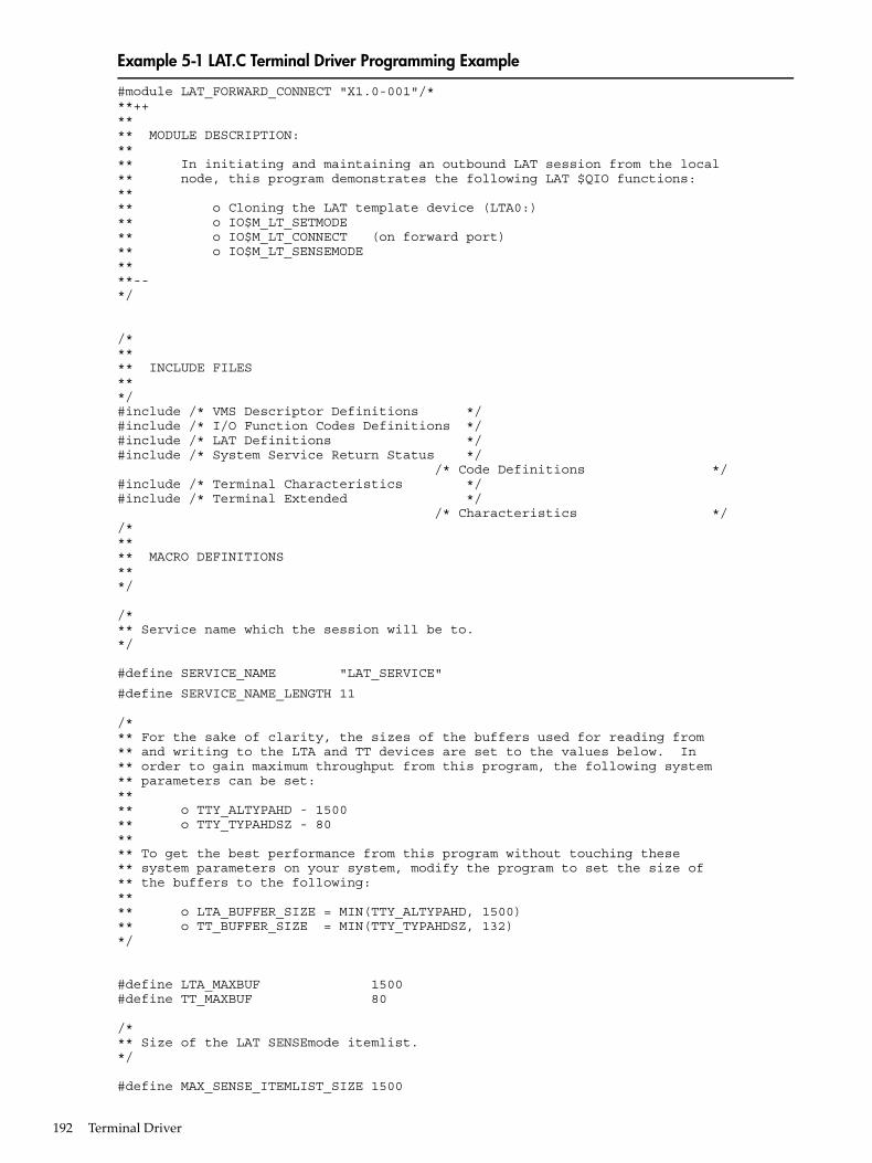
Example 5-1 LAT.C Terminal Driver Programming Example
#module LAT_FORWARD_CONNECT "X1.0-001"/***++**** MODULE DESCRIPTION:**** In initiating and maintaining an outbound LAT session from the local** node, this program demonstrates the following LAT $QIO functions:**** o Cloning the LAT template device (LTA0:)** o IO$M_LT_SETMODE** o IO$M_LT_CONNECT (on forward port)** o IO$M_LT_SENSEMODE****--*/
/***** INCLUDE FILES***/#include /* VMS Descriptor Definitions */#include /* I/O Function Codes Definitions */#include /* LAT Definitions */#include /* System Service Return Status */ /* Code Definitions */#include /* Terminal Characteristics */#include /* Terminal Extended */ /* Characteristics *//***** MACRO DEFINITIONS***/
/*** Service name which the session will be to.*/
#define SERVICE_NAME "LAT_SERVICE"
#define SERVICE_NAME_LENGTH 11
/*** For the sake of clarity, the sizes of the buffers used for reading from** and writing to the LTA and TT devices are set to the values below. In** order to gain maximum throughput from this program, the following system** parameters can be set:**** o TTY_ALTYPAHD - 1500** o TTY_TYPAHDSZ - 80**** To get the best performance from this program without touching these** system parameters on your system, modify the program to set the size of** the buffers to the following:**** o LTA_BUFFER_SIZE = MIN(TTY_ALTYPAHD, 1500)** o TT_BUFFER_SIZE = MIN(TTY_TYPAHDSZ, 132)*/
#define LTA_MAXBUF 1500#define TT_MAXBUF 80
/*** Size of the LAT SENSEmode itemlist.*/
#define MAX_SENSE_ITEMLIST_SIZE 1500
192 Terminal Driver

/*** Character user can press to terminate the LAT connection (CTRL+\).*/
#define CONNECTION_TERMINATOR 0x1C
/***** FUNCTION PROTOTYPES***/
unsigned long SetDeviceChars(void);void ConnectAST(void);void LTAreadChannelAST(void);void TTreadChannelAST(void);void LTAhangupHandler(void);void EndSession(void);void ExitHandler(void);
/***** GLOBAL DATA***/
char *LTAbuffer, /* LTA device I/O buffer */ *TTbuffer, /* TT device I/O buffer */
/* ** Text for LAT reject codes. Note that some LAT ** implementations will return a 0 reject code to ** indicate a normal disconnect. */
*LATrejectTable[] = { "Unknown", "User requested disconnect", "System shutdown in progress", "Invalid slot received", "Invalid service class received", "Insufficient resources at server", "Port or service in use", "No such service", "Service is disabled", "Service is not offeredon the requested port", "Port name is unknown", "Invalid service password", "Remote entry is not in queue", "Immediate access rejected", "Access denied", "Corrupted request", "Requested function is not supported", "Session cannot be started", "Queue entry deleted by server", "Illegal request parameters" };
unsigned short LTAchannel, /* LTA device I/O channel */ TTchannel, /* TT device I/O channel */ LTA_QIOiosb[4], /* IOSB for LTA device functions */ TT_QIOiosb[4]; /* IOSB for TT device functions */
unsigned long ReadTerminatorMask[2] = { 0, 0 }, /* $QIO read terminator mask */ SavedTTdeviceChar[3], /* Saved TT device characteristics */ DeviceCharBuffSize = sizeof(SavedTTdeviceChar); /* Size of device characteristics buffer*/ ExitConditionValue, /* Exit condition value of program */
5.5 Terminal Driver Programming Examples 193

LATrejectTableSize =/* Number of elements in LAT reject tbl */ sizeof(LATrejectTable) / sizeof(LATrejectTable[0]);
/*** Itemlist for setting LAT port with the target service name.*/
struct { unsigned short item_code; char item_byte_count; char item_value[ SERVICE_NAME_LENGTH ];} PortSetmodeItemlist = { LAT$_ITM_TARGET_SERVICE_NAME, SERVICE_NAME_LENGTH, SERVICE_NAME};
/*** Exit handler block.*/
struct { unsigned long flink; void (*exit_handler)(); unsigned long arg_count; unsigned long *exit_status;} ExitHandlerBlock = { 0, ExitHandler, 1, };
/*** Devices which channels are assigned to.*/
$DESCRIPTOR(LTAtemplateDSC, "LTA0:");$DESCRIPTOR(TTchannelDSC, "SYS$COMMAND");
main(){ /* ** Local Variables: */
unsigned long status, portSetmodeItemlistSize = sizeof(PortSetmodeItemlist);
/* ** BEGIN: ** ** Declare an exit handler. */
if (!( (status = sys$dclexh() ) & 1) ) lib$signal(status);
/* ** Assign a channel to LTA0: to get a forward LAT port and assign a ** channel to the terminal. */
if (!( (status = sys$assign(, , 0, 0) ) & 1) ) lib$signal(status); if (!( (status = sys$assign(, , 0, 0) ) & 1) ) lib$signal(status);
/* ** Allocate memory for the channel data buffers. */
LTAbuffer = malloc(LTA_MAXBUF); TTbuffer = malloc(TT_MAXBUF);
/* ** Set device characteristics for the two channels.
194 Terminal Driver

*/
if (!( (status = SetDeviceChars() ) & 1) ) lib$signal(status);
/* ** Do SETmode $QIO to set the port entity with the target service name ** specified in the item list. */
if (!( (status = sys$qiow( 0, LTAchannel, IO$_TTY_PORT|IO$M_LT_SETMODE, _QIOiosb, 0, 0, , portSetmodeItemlistSize, LAT$C_ENT_PORT|(LAT$C_ENTS_OLD << 0x10), 0, 0, 0) ) & 1) ) lib$signal(status); if (!(LTA_QIOiosb[0] & 1) ) lib$signal(LTA_QIOiosb[0]);
/* ** Enable a CTRL+Y AST on the LAT channel. */
if (!( (status = sys$qiow( 0, LTAchannel, IO$_SETMODE|IO$M_CTRLYAST, _QIOiosb, 0, 0, LTAhangupHandler, 0, 0, 0, 0, 0) ) & 1) ) lib$signal(status); if (!(LTA_QIOiosb[0] & 1) ) lib$signal(LTA_QIOiosb[0]);
/* ** Post the first read (with AST) on the LTA device to ensure that the ** first burst of data from the target service is not lost. It is very ** important that the first read is queued before doing the connect ** $QIO to ensure no data lossage. */
if (!( (status = sys$qio( 0, LTAchannel, IO$_READVBLK|IO$M_NOECHO, _QIOiosb, LTAreadChannelAST, 0, LTAbuffer, 1, 0, , 0, 0) ) & 1) ) lib$signal(status);
/* ** Do the LAT connect $QIO and hibernate until program exit. The ** ConnectAST will execute when the connection completes and post the ** initial read on the TT channel. */
if (!( (status = sys$qio( 0, LTAchannel, IO$_TTY_PORT|IO$M_LT_CONNECT, _QIOiosb, ConnectAST, 0, 0, 0, 0, 0, 0, 0) ) & 1) ) lib$signal(status); sys$hiber();
} /* END - main() */
5.5 Terminal Driver Programming Examples 195

/***++**** FUNCTIONAL DESCRIPTION:**** This routine sets device characteristics of the LTA and TT devices.** The HOSTSYNC, NOBRDCST, EIGHTBIT and PASTHRU characteristics are set** on the LTA device. The ESCAPE and TTSYNC characteristics are cleared.**** The TTSYNC, HOSTSYNC, EIGHTBIT, and PASTHRU characteristics are set** on the TT device. The ESCAPE characteristic is cleared. The TT** characterisitcs are also saved for restoration at program exit.****--*/
unsigned long SetDeviceChars(void){ /* ** Local Variables: */
unsigned long status, deviceChar[3];
/* ** BEGIN: ** ** Mask and set the characteristics of the LTA device. Sense the ** current characteristics, and mask in and set the new ones. */
if (!( (status = sys$qiow( 0, LTAchannel, IO$_SENSEMODE, _QIOiosb, 0, 0, , DeviceCharBuffSize, 0, 0, 0, 0) ) & 1) ) lib$signal(status); if (!(LTA_QIOiosb[0] & 1) ) lib$signal(LTA_QIOiosb[0]);
deviceChar[1] = (deviceChar[1] | (TT$M_HOSTSYNC | TT$M_NOBRDCST | TT$M_EIGHTBIT) ) & ~TT$M_ESCAPE & ~TT$M_TTSYNC; deviceChar[2] |= TT2$M_PASTHRU;
if (!( (status = sys$qiow( 0, LTAchannel, IO$_SETMODE, &TT_QIOiosb, 0, 0, &deviceChar DeviceCharBuffSize, 0, 0, 0, 0) ) & 1) ) lib$signal(status); if (!(LTA_QIOiosb[0] & 1) ) lib$signal(LTA_QIOiosb[0]);
/* ** Repeat the procedure for TT device characteristics. However, save ** the current characteristics for restoration at program exit. */
if (!( (status = sys$qiow( 0, TTchannel, IO$_SENSEMODE,
196 Terminal Driver

$TT_QIOiosb, 0, 0, &SavedTTdeviceChar DeviceCharBuffSize, 0, 0, 0, 0) ) & 1) ) lib$signal(status); if (!(TT_QIOiosb[0] & 1) ) lib$signal(TT_QIOiosb[0]);
deviceChar[0] = SavedTTdeviceChar[0]; deviceChar[1] = (SavedTTdeviceChar[1] | (TT$M_TTSYNC | TT$M_HOSTSYNC | TT$M_EIGHTBIT) ) & ~TT$M_ESCAPE; deviceChar[2] = SavedTTdeviceChar[2] | TT2$M_PASTHRU;
if (!( (status = sys$qiow( 0, TTchannel, IO$_SETMODE, &TT_QIOiosb, 0, 0, &deviceChar DeviceCharBuffSize, 0, 0, 0, 0) ) & 1) ) lib$signal(status); if (!(TT_QIOiosb[0] & 1) ) lib$signal(TT_QIOiosb[0]);
return(status);
} /* END - SetDeviceChars */
/***++**** FUNCTIONAL DESCRIPTION:**** This routine is an AST which executes when the connect $QIO completes.** First the IOSB is checked. If the connection timed out or was aborted,** simply end the session. Any other abnormal status causes the program** to exit.**** Otherwise the connection completed successfully and a read on the TT** channel is posted.****--*/
void ConnectAST(){ /* ** Local Variables: */
unsigned long status;
/* ** BEGIN: ** ** If the status in the IOSB indicates that the connection timed out ** or aborted, call the session end routine. Any other abnormal ** status causes program exit. */
if ( (LTA_QIOiosb[0] == SS$_TIMEOUT) || (LTA_QIOiosb[0] == SS$_ABORT) ) EndSession();
if (!(LTA_QIOiosb[0] & 1) ) sys$exit(LTA_QIOiosb[0]);
/* ** The connection completed successfully! Post a read (with AST) on ** the TT device and return. */
5.5 Terminal Driver Programming Examples 197

if (!( (status = sys$qio( 0, TTchannel, IO$_READVBLK|IO$M_NOECHO, &TT_QIOiosb, TTreadChannelAST, 0, TTbuffer, 1, 0, &ReadTerminatorMask 0, 0) ) & 1) ) lib$signal(status);
return;
} /* END - ConnectAST */
/***++**** FUNCTIONAL DESCRIPTION:**** This routine is an AST which executes when the first character read on** the LTA channel completes. It does a "flush" read of the channel to** drain any data out of the ALTYPAHD buffer and writes the data to the** TT channel. It then posts another read on the channel.****--*/
void LTAreadChannelAST(void){ /* ** Local Variables: */
unsigned long status;
/* ** BEGIN: ** ** If the status in the IOSB indicates channel hangup, simply end the ** session. Signal any other abnormal status. */
if (LTA_QIOiosb[0] == SS$_HANGUP) EndSession(); if (!(LTA_QIOiosb[0] & 1) ) lib$signal(LTA_QIOiosb[0]);
/* ** Do a "flush" read of the LTA device. This is done by doing a timed ** read with a 0 timeout. There may or may not be any data to drain. ** This method is more efficient than using single character reads. */
if (!( (status = sys$qiow( 0, LTAchannel, IO$_READVBLK|IO$M_TIMED|IO$M_NOECHO, _QIOiosb, 0, 0, LTAbuffer+1, LTA_MAXBUF-1, 0, &ReadTerminatorMask, 0, 0) ) & 1) ) lib$signal(status); if (!(LTA_QIOiosb[0] & 1) && (LTA_QIOiosb[0] != SS$_TIMEOUT) ) lib$signal(LTA_QIOiosb[0]);
/* ** The second word of the IOSB contains the number of characters ** read. Write the characters plus 1 for the initial read to the ** TT device.
198 Terminal Driver
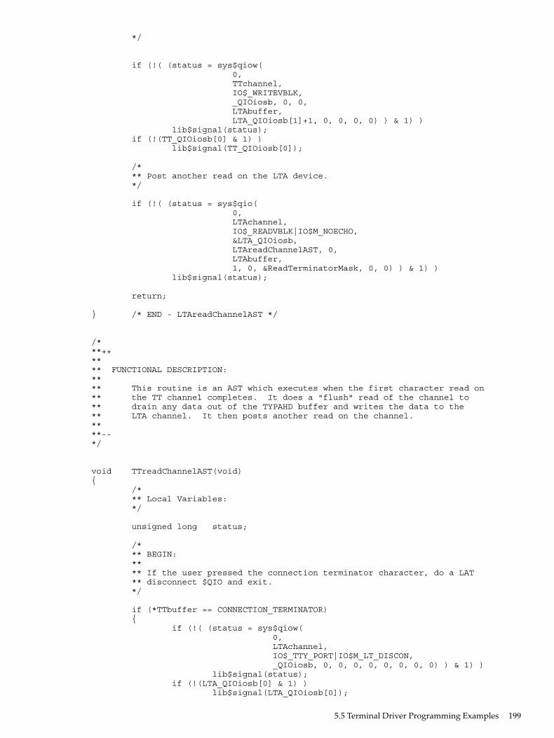
*/
if (!( (status = sys$qiow( 0, TTchannel, IO$_WRITEVBLK, _QIOiosb, 0, 0, LTAbuffer, LTA_QIOiosb[1]+1, 0, 0, 0, 0) ) & 1) ) lib$signal(status); if (!(TT_QIOiosb[0] & 1) ) lib$signal(TT_QIOiosb[0]);
/* ** Post another read on the LTA device. */
if (!( (status = sys$qio( 0, LTAchannel, IO$_READVBLK|IO$M_NOECHO, <A_QIOiosb, LTAreadChannelAST, 0, LTAbuffer, 1, 0, &ReadTerminatorMask, 0, 0) ) & 1) ) lib$signal(status);
return;
} /* END - LTAreadChannelAST */
/***++**** FUNCTIONAL DESCRIPTION:**** This routine is an AST which executes when the first character read on** the TT channel completes. It does a "flush" read of the channel to** drain any data out of the TYPAHD buffer and writes the data to the** LTA channel. It then posts another read on the channel.****--*/
void TTreadChannelAST(void){ /* ** Local Variables: */
unsigned long status;
/* ** BEGIN: ** ** If the user pressed the connection terminator character, do a LAT ** disconnect $QIO and exit. */
if (*TTbuffer == CONNECTION_TERMINATOR) { if (!( (status = sys$qiow( 0, LTAchannel, IO$_TTY_PORT|IO$M_LT_DISCON, _QIOiosb, 0, 0, 0, 0, 0, 0, 0, 0) ) & 1) ) lib$signal(status); if (!(LTA_QIOiosb[0] & 1) ) lib$signal(LTA_QIOiosb[0]);
5.5 Terminal Driver Programming Examples 199

return; }
/* ** Do a "flush" read of the TT device. This is done by doing a timed ** read with a 0 timeout. There may or may not be any data to drain. */
if (!( (status = sys$qiow( 0, TTchannel, IO$_READVBLK|IO$M_TIMED|IO$M_NOECHO, _QIOiosb, 0, 0, TTbuffer+1, TT_MAXBUF-1, 0, &ReadTerminatorMask, 0, 0) ) & 1) ) lib$signal(status); if (!(TT_QIOiosb[0] & 1) && (TT_QIOiosb[0] != SS$_TIMEOUT) ) lib$signal(TT_QIOiosb[0]);
/* ** The second word of the IOSB contains the number of characters ** read. Write the characters plus 1 for the initial read to the ** TT device. */
if (!( (status = sys$qiow( 0, LTAchannel, IO$_WRITEVBLK, _QIOiosb, 0, 0, TTbuffer, TT_QIOiosb[1]+1, 0, 0, 0, 0) ) & 1) ) lib$signal(status);
/* ** If the status in the IOSB indicates channel hangup, simply end ** the session. Signal any other abnormal status. */
if (LTA_QIOiosb[0] == SS$_HANGUP) EndSession(); if (!(LTA_QIOiosb[0] & 1) ) lib$signal(LTA_QIOiosb[0]);
/* ** Post another read on the LTA device. */
if (!( (status = sys$qio( 0, TTchannel, IO$_READVBLK|IO$M_NOECHO, _QIOiosb, TTreadChannelAST, 0, TTbuffer, 1, 0, &ReadTerminatorMask, 0, 0) ) & 1) ) lib$signal(status);
return;
} /* END - TTreadChannelAST */
/***++**** FUNCTIONAL DESCRIPTION:**** This routine is the CTRL+Y AST for the LTA channel. It executes when
200 Terminal Driver

** a hangup on the LTA channel is recognized (connection timed out or** aborted). It will call the session end routine if it hasn't already** been called by ConnectAST.**** NOTE: CTRL+Y ASTs for application ports will NOT execute when the** connection is disconnected.****--*/
void LTAhangupHandler(void){ /* ** BEGIN: ** ** Call the session end routine and return. */
EndSession(); return;
} /* END - LTAhanghupHandler */
/***++**** FUNCTIONAL DESCRIPTION:**** This routine is executed at session end. It will do a $QIO SENSEmode** and search the resulting itemlist to find the reason for the LAT** disconnect. The reason for the disconnect is displayed on the** terminal and the image exits.****--*/
void EndSession(void){
/* ** Local Variables: */
struct ITEM_ENTRY *itemlistEntry; unsigned long status; char *senseItemlist = malloc(MAX_SENSE_ITEMLIST_SIZE), *itemlistEntryPointer;
/* ** BEGIN: ** ** Do the SENSEmode on the port. */
if (!( (status = sys$qiow( 0, LTAchannel, IO$_TTY_PORT|IO$M_LT_SENSEMODE, <A_QIOiosb, 0, 0, senseItemlist, MAX_SENSE_ITEMLIST_SIZE, LAT$C_ENT_PORT|(LAT$M_SENSE_FULL << 0x10), 0, 0, 0) ) & 1) ) lib$signal(status); if (!(LTA_QIOiosb[0] & 1) ) lib$signal(LTA_QIOiosb[0]);
/* ** Set up two pointers used to traverse the itemlist. */
5.5 Terminal Driver Programming Examples 201

itemlistEntry = (struct ITEM_ENTRY *) senseItemlist; itemlistEntryPointer = senseItemlist;
/* ** Search the itemlist for the LAT$_ITM_DISCONNECT_REASON code to find ** out why the connection terminated. */
while (itemlistEntry->LAT$R_ITM_CODE.LAT$W_ITEMCODE != LAT$_ITM_DISCONNECT_REASON) { /* ** If the current itemcode being checked has a string value, ** advance the pointer to the next itemcode by skipping ** BCNT bytes plus 3 bytes for the BCNT byte itself and the ** 2 byte itemcode. */
if (itemlistEntry-> LAT$R_ITM_CODE.LAT$R_ITM_BITS.LAT$V_STRING) itemlistEntryPointer += itemlistEntry->LAT$R_ITEM_VALUE. LAT$R_ITEM_COUNTED_STRING.LAT$B_ITEM_BCNT + 3;
/* ** If the current itemcode being checked has a scalar value, ** advance the pointer to the next itemcode by skipping 6 ** bytes for the itemcode and the 4 byte scalar. */
else itemlistEntryPointer += 6; itemlistEntry = (struct ITEM_ENTRY *) itemlistEntryPointer; }
/* ** If the disconnect reason is a LAT reject code, print out the ** text corresponding to the code and set the exit condition value ** to SS$_NORMAL. */
if (itemlistEntry->LAT$R_ITEM_VALUE.LAT$L_ITEM_SCALAR_VALUE <= LATrejectTableSize) { printf("\nSession disconnected. Reason: %s\n\n\n", LATrejectTable[ itemlistEntry->LAT$R_ITEM_VALUE. LAT$L_ITEM_SCALAR_VALUE ]); ExitConditionValue = SS$_NORMAL; }
/* ** The scalar value is a LAT facility message code. Set the exit ** condition value to be the scalar. Upon image exit, the ** corresponding LAT facility message will be displayed. */
else ExitConditionValue = itemlistEntry->LAT$R_ITEM_VALUE.LAT$L_ITEM_SCALAR_VALUE;
sys$exit(ExitConditionValue);
} /* END - EndSession */
/***++**** FUNCTIONAL DESCRIPTION:**
202 Terminal Driver

** This is the program exit handler which is executed upon image exit.** It will cancel all pending I/O on the two channels and restore the** TT channel characteristics.****--*/
void ExitHandler(void){ /* ** Local Variables: */
unsigned long status;
/* ** BEGIN: ** ** Cancel I/O on the channels, reset terminal characteristics and ** return. */
if (!( (status = sys$cancel(LTAchannel) ) & 1) ) lib$signal(status); if (!( (status = sys$cancel(TTchannel) ) & 1) ) lib$signal(status);
if (!( (status = sys$qiow( 0, TTchannel, IO$_SETMODE, &TT_QIOiosb, 0, 0, &SavedTTDeviceChar, DeviceCharBuffSize, 0, 0, 0, 0) ) & 1) ) lib$signal(status); if (!(TT_QIOiosb[0] & 1) ) lib$signal(TT_QIOiosb[0]);
return;
} /* END - ExitHandler */
The MACRO 32 program FULL_DUPLEX_TERMINAL.MAR (Example 5-2) shows several I/Ooperations using the full-duplex capabilities of the terminal. This program shows some importantconcepts about terminal driver programming: assigning an I/O channel, performing full-duplexI/O operations, enabling Ctrl/C AST requests, and itemlist read operations. The program isdesigned to run with a terminal set to full-duplex mode.The initialization code queues a read request to the terminal and enables Ctrl/C AST requests.The main loop then prints out a random message every three seconds. When you enter a messageon the terminal, the read AST routine prints an acknowledgment message and queues anotherread request. If you press Ctrl/C, the associated AST routine cancels the I/O operation on theassigned channel and exits to the command interpreter.
5.5 Terminal Driver Programming Examples 203

Example 5-2 FULL_DUPLEX_TERMINAL.MAR Terminal Driver Programming Example
.TITLE FULL_DUPLEX TERMINAL PROGRAMMING EXAMPLE .IDENT /05/
; ********************************************************************;; TERMINAL PROGRAM;; ********************************************************************
.SBTTL DECLARATIONS .DISABLE GLOBAL
;; Declare the external symbols and MACRO libraries.;
.EXTERNAL LIB$GET_EF .LIBRARY 'SYS$LIBRARY:LIB.MLB' .LIBRARY 'SYS$LIBRARY:STARLET.MLB';; Define symbols;
$IODEF ; Define I/O function codes $QIODEF ; Define QIO definition codes $SSDEF ; Define the system service status codes $TRMDEF ; Define itemlist read codes $TTDEF ; Terminal characteristic definitions
;; Define macros; .SHOW .MACRO ITEM LEN=0,CODE,VALUE .WORD LEN .WORD TRM$_'CODE' .LONG VALUE .LONG 0 .ENDM ITEM .NOSHOW
;; Declare exit handler control block;EXIT_HANDLER_BLOCK: .LONG 0 ; System uses this for pointer .LONG EXIT_HANDLER ; Address of exit handler .LONG 1 ; Argument count for handler .LONG STATUS ; Destination of status codeSTATUS: .BLKL 1 ; Status code from $EXIT
;; Allocate terminal descriptor and channel number storage;
TT_DESC: .ASCID /SYS$INPUT/ ; Logical name of terminalTT_CHAN: .BLKW 1 ; TT channel number storage
;; Define acknowledgment message. This is done right above input buffer; so that we can concatenate the two together when the acknowledgment; message is issued.;
ACK_MSG: .ASCII <CR> /Following input acknowledged: /ACK_MSGLEN=.-ACK_MSG ; Calculate length of message
;; Allocate input buffer;
IN_BUFLEN = 20 ; Set length of bufferIN_BUF: .BLKB IN_BUFLEN ; Allocate character bufferIN_IOSB:
204 Terminal Driver

.BLKQ 1 ; Input I/O status block;; Define out-of-band ast character mask;CNTRLA_MASK: .LONG 0 .LONG ^B0010 ; Control A mask
;; Define old terminal characteristics buffer;OLDCHAR_BUF_LEN = 12OLDCHAR_BUF: .BLKB OLDCHAR_BUF_LEN
;; Define new terminal characteristics buffer;NEWCHAR_BUF_LEN = 12NEWCHAR_BUF: .BLKB NEWCHAR_BUF_LEN
;; Define carriage control symbols;
CR=^X0D ; Carriage return LF=^X0A ; Line feed
;; Define output messages;; Output messages are accessed by indexing into a table of; longwords with each message described by a message address and; message length;
ARRAY: ; Table of message addresses and ; lengths .LONG 10$ ; First message address .LONG 15$ ; First message length .LONG 20$ .LONG 25$ .LONG 30$ .LONG 35$ .LONG 40$ .LONG 45$;; Define messages;
10$: .ASCII <CR>/RED ALERT! RED ALERT!/15$=.-10$;20$: .ASCII <CR>/ALL SYSTEMS GO/25$=.-20$;30$: .ASCII <CR>/WARNING..INTRUDER ALARM/35$=.-30$;40$: .ASCII <CR>/** SYSTEM OVERLOAD **/45$=.-40$;; Static QIO packet for message output using QIO$_G form;
WRITE_QIO: $QIO EFN=SYNC_EFN, - ; QIO packet FUNC=IO$_WRITEVBLK!IO$M_BREAKTHRU!IO$M_REFRESH, - IOSB=SYNC_IOSB
;; Declare the required I/O status blocks.;SYNC_IOSB:: .BLKQ 1 ; I/O status block for synchronous terminal processing.
;; Declare the required event flags.
5.5 Terminal Driver Programming Examples 205

;ASYNC_EFN:: .BLKL 1 ; Event flag for asynchronous terminal processing.SYNC_EFN == WRITE_QIO + 4 ; Event flag for sync terminal processing.TIMER_EFN:: .BLKL 1 ; Event flag for timer processing.
;; Timer storage;
WAITIME: .LONG -10*1000*1000*3,-1 ; 3 second delta timeTIME: .BLKQ 1 ; Current storage time used for ; random number
.PAGE .SBTTL START - MAIN ROUTINE .ENABLE LOCAL_BLOCK;++;; Functional description:;; ********************************************************************;; Start program;; ********************************************************************;; The following code performs initialization functions.; It is assumed that the terminal is already in; FULL-DUPLEX mode.;; NOTE: When doing QIO_S calls, parameters P1 and P3-P6 should be; passed by value, while P2 should be passed by reference.;; Input parameters:; None;; Output parameters:; None;;-- .ENTRY START ^M < >
; Get the required event flags.
PUSHAL ASYNC_EFN CALLS # 1, G^ LIB$GET_EF ; Get EFN for async terminal operations. BLBC R0, 10$ ; Error - branch. PUSHAL SYNC_EFN CALLS # 1, G^ LIB$GET_EF ; Get EFN for sync terminal operations. BLBC R0, 10$ ; Error - branch. PUSHAL TIMER_EFN CALLS # 1, G^ LIB$GET_EF ; Get EFN for timer operations. BLBC R0, 10$ ; Error - branch.
; Initialize the terminal characteristics.
$ASSIGN_S DEVNAM=TT_DESC,-; Assign terminal channel using CHAN=TT_CHAN ; logical name and channel number BLBC R0, 10$ ; Error - branch. BSBW CHANGE_CHARACTERISTICS ; Change the characteristics of ; terminal BSBW ENABLE_CTRLCAST ; Allow Ctrl/C traps BSBW ENABLE_OUTBANDAST ; Enable Ctrl/A out-of-band AST BSBW ENABLE_READ ; Queue read MOVZWL TT_CHAN, WRITE_QIO+8 ; Insert channel into BRB LOOP ; static QIO packet
10$: BRW ERROR
;; This loop outputs a message based on a random number and then; delays for 3 seconds;
LOOP: $GETTIM_S TIMADR=TIME ; Get random time
206 Terminal Driver

BLBC R0, 10$ ; Error - branch. EXTZV #6, #2, TIME, R0 ; Load random bits into switch MOVQ ARRAY[R0], - ; Load message address WRITE_QIO+QIO$_P1 ; and size into QIO ; packet
;; Issue QIO write using packet defined in data area;
$QIOW_G WRITE_QIO BLBC R0, 10$ ; QIO error - branch. MOVZWL SYNC_IOSB, R0 ; Get the terminal driver status. BLBC R0, 10$ ; Terminal driver error - branch.
;; Delay for 3 seconds before issuing next message;
$SETIMR_S EFN=TIMER_EFN,- ; Timer service DAYTIM=WAITIME ; will set event flag ; in 3 seconds BLBC R0, 10$ ; Error - branch. $WAITFR_S EFN=TIMER_EFN ; Wait for event flag BLBS R0, LOOP ; No error if set BRB 10$ ; Error - branch.
.DISABLE LOCAL_BLOCK
.PAGE .SBTTL CHANGE_CHARACTERISTICS - CHANGE CHARACTERISTICS OF TERMINAL;++;; Functional description:;; Routine to change the characteristics of the terminal.;; Input parameters:; None;; Output parameters:; R0 - status from $QIO call.; R1 - R5 destroyed;;--;
CHANGE_CHARACTERISTICS: $QIOW_S EFN=SYNC_EFN, - ; Get current terminal characteristics CHAN=TT_CHAN, - FUNC=#IO$_SENSEMODE, - IOSB=SYNC_IOSB, - P1=OLDCHAR_BUF, - P2=#OLDCHAR_BUF_LEN BLBC R0, 10$ ; Error if clear MOVZWL SYNC_IOSB, R0 ; Get the terminal driver status. BLBC R0, 10$ ; Error - branch
$DCLEXH_S EXIT_HANDLER_BLOCK ; Declare exit handler to reset ; characteristics BLBC R0, 10$ ; Error - branch. MOVC3 #OLDCHAR_BUF_LEN, - ; Move old characteristics into OLDCHAR_BUF, - ; new characteristics buffer NEWCHAR_BUF BISL2 #TT$M_NOBRDCST, - ; Set nobroadcast bit NEWCHAR_BUF+4 ; ... $QIOW_S EFN=SYNC_EFN, - ; Set current terminal characteristics CHAN=TT_CHAN, - FUNC=#IO$_SETMODE, - IOSB=SYNC_IOSB, - P1=NEWCHAR_BUF, - P2=#NEWCHAR_BUF_LEN BLBC R0, 10$ ; QIO error - branch. MOVZWL SYNC_IOSB, R0 ; Get the terminal driver status. BLBC R0, 10$ ; Terminal driver error - branch. RSB10$:
5.5 Terminal Driver Programming Examples 207

BRW ERROR
.PAGE .SBTTL ENABLE_CTRLCAST - ENABLE Ctrl/C AST;++;; Functional description:;; Routine to allow Ctrl/C recognition.;; Input parameters:; None;; Output parameters:; None;;--;
ENABLE_CTRLCAST: $QIOW_S EFN=SYNC_EFN, - CHAN=TT_CHAN, - FUNC=#IO$_SETMODE!IO$M_CTRLCAST, - IOSB=SYNC_IOSB, - P1=CTRLCAST, - ; AST routine address P3=#3 ; User mode BLBC R0, 10$ ; Error - branch. MOVZWL SYNC_IOSB, R0 ; Get the terminal driver status. BLBC R0, 10$ ; Terminal driver error - branch. RSB
10$: BRW ERROR
.PAGE .SBTTL ENABLE_OUTBANDAST - ENABLE Ctrl/A AST;++;; Functional description:;; Routine to allow CNTRL/A recognition.;; Input parameters:; None;; Output parameters:; None;
ENABLE_OUTBANDAST: $QIOW_S EFN=SYNC_EFN, - CHAN=TT_CHAN, - FUNC=#IO$_SETMODE!IO$M_OUTBAND, - IOSB=SYNC_IOSB, - P1=CTRLAAST, - ; AST routine address P2=#CNTRLA_MASK, - ; Character mask P3=#3 ; User mode BLBC R0, 10$ ; QIO error - branch. MOVZWL SYNC_IOSB, R0 ; Get the terminal driver status. BLBC R0, 10$ ; Terminal driver error - branch. RSB
10$: BRW ERROR
.PAGE .SBTTL ENABLE_READ - QUEUE A READ TO THE TERMINAL.;++;; Functional description:;; Routine to queue a read operation to the terminal.;; Input parameters:; None;; Output parameters:; None;
208 Terminal Driver

; Define item list for itemlist read;ITEM_LST: ITEM 0, MODIFIERS, - ; Convert lowercase to TRM$M_TM_CVTLOW!TRM$M_TM_NOEDIT ; upper and inhibit line ITEM 6, TERM,MASK_ADDR ; editing ; Set up terminator mask
ITEM_LEN = . - ITEM_LSTMASK_ADDR: .LONG 1@^XD ; Terminator mask is ; <CR>.WORD 1@4 ; and "$"ENABLE_READ: $QIO_S EFN=ASYNC_EFN, - ; Must not be QIOW form or read will block CHAN=TT_CHAN, - ; process FUNC=#IO$_READVBLK!IO$M_EXTEND, - IOSB=IN_IOSB, - ASTADR=READAST, - ; AST routine to execute P1=IN_BUF, - ; on P2=#IN_BUFLEN, - P5=#ITEM_LST, - ; Itemlist read address P6=#ITEM_LEN ; Itemlist read size BLBC R0, 10$ ; QIO error - branch.
; The queued read operation will not affect write operations due; to the fact that breakthru has been set for the write operations.
RSB
10$: BRW ERROR
.PAGE .SBTTL READAST - AST ROUTINE FOR READ COMPLETION .ENABLE LOCAL_BLOCK;++;; Functional description:;; AST routine to execute on read completion.;; Input parameters:; None;; Output parameters:; None;;--;
10$: MOVZWL IN_IOSB, R0 ; Get the terminal driver status20$: BRW ERROR ; Exit with error status.
.ENTRY READAST ^M < R2, R3, R4, R5 > ; Procedure entry mask
BLBC IN_IOSB, 10$ ; Terminal driver error - branch MOVZWL IN_IOSB+2, R0 ; Get number of characters read into R0 ADDL2 #ACK_MSGLEN, R0 ; Add size of fixed acknowledge message $QIO_S EFN=ASYNC_EFN, - ; Issue acknowledge message CHAN=TT_CHAN, - ; Note, ACK must be asynchronous (QIO) FUNC=#IO$_WRITEVBLK, - ; and the terminal driver write status P1=ACK_MSG, - ; is ignored (no IOSB and AST routine). P2=R0 ; Specify IOSB and AST routine if output ; must be displayed on the terminal. BLBC R0, 20$ ; QIO error - branch
;; Process read message;; .; .; .;(user-provided code to decode command inserted here); .; .; .
5.5 Terminal Driver Programming Examples 209

BSBW ENABLE_READ ; Queue next read RET ; Return to mainline loop
.DISABLE LOCAL_BLOCK
.PAGE .SBTTL CTRLAAST - AST ROUTINE FOR Ctrl/A .SBTTL CTRLCAST - AST ROUTINE FOR Ctrl/C .SBTTL ERROR - EXIT ROUTINE;++;; Functional description:;; AST routine to execute when Ctrl/C or Ctrl/A is entered.;; Input parameters:; None;; Output parameters:; None;
CTRLCAST::CTRLAAST:: .WORD ^M < > ; Procedure entry mask MOVL #SS$_NORMAL, R0 ; Put success in R0
ERROR:: $EXIT_S R0 ; Exit RSB
.PAGE .SBTTL EXIT_HANDLER - EXIT HANDLER ROUTINE;++;; Functional description:;; Exit handler routine to execute when image exits. It cancels; any outstanding I/O on this channel and resets the terminal; characteristics to their original state.;; Input parameters:; None;; Output parameters:; None;;--;
.ENTRY EXIT_HANDLER ^M< > $CANCEL_S CHAN=TT_CHAN ; Flush any I/O on queue $QIOW_S EFN=SYNC_EFN, - ; Reset terminal characteristics CHAN=TT_CHAN, - FUNC=#IO$_SETMODE, - IOSB=SYNC_IOSB, - P1=OLDCHAR_BUF, - P2=#OLDCHAR_BUF_LEN BLBC R0, 10$ ; QIO error - branch. MOVZWL SYNC_IOSB, R0 ; Get the terminal driver status.
10$: RET
.END START
The MACRO 32 program READ_VERIFY.MAR (Example 5-3) shows the read verify function.The program shows a typical build of itemlists (both the right and left fields), channel assignment,a right- and left-justified read verify operation, and then the read QIO operation.
210 Terminal Driver
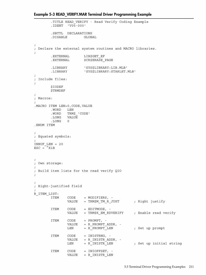
Example 5-3 READ_VERIFY.MAR Terminal Driver Programming Example
.TITLE READ_VERIFY - Read Verify Coding Example .IDENT 'V05-000'
.SBTTL DECLARATIONS .DISABLE GLOBAL
;; Declare the external system routines and MACRO libraries.; .EXTERNAL LIB$GET_EF .EXTERNAL SCR$ERASE_PAGE
.LIBRARY 'SYS$LIBRARY:LIB.MLB' .LIBRARY 'SYS$LIBRARY:STARLET.MLB';; Include files:; $IODEF $TRMDEF;; Macros:;.MACRO ITEM LEN=0,CODE,VALUE .WORD LEN .WORD TRM$_'CODE' .LONG VALUE .LONG 0.ENDM ITEM
;; Equated symbols:;INBUF_LEN = 20ESC = ^X1B
;; Own storage:;; Build item lists for the read verify QIO;
;; Right-justified field;R_ITEM_LIST: ITEM CODE = MODIFIERS, - VALUE = TRM$M_TM_R_JUST ; Right justify
ITEM CODE = EDITMODE, - VALUE = TRM$K_EM_RDVERIFY ; Enable read verify
ITEM CODE = PROMPT, - VALUE = R_PROMPT_ADDR, - LEN = R_PROMPT_LEN ; Set up prompt
ITEM CODE = INISTRNG, - VALUE = R_INISTR_ADDR, - LEN = R_INISTR_LEN ; Set up initial string
ITEM CODE = INIOFFSET, - VALUE = R_INISTR_LEN
5.5 Terminal Driver Programming Examples 211

ITEM CODE = PICSTRNG, - VALUE = R_PICSTR_ADDR, - LEN = R_PICSTR_LEN ; Set up picture string
ITEM CODE = FILLCHR, - VALUE = <^A/* /> ; clear = *, fill = space
R_ITEM_LIST_LEN = .-R_ITEM_LIST
R_PROMPT_ADDR: .ASCII /[12;12H$/R_PROMPT_LEN = .-R_PROMPT_ADDR
R_INISTR_ADDR: .ASCII / , /R_INISTR_LEN = .-R_INISTR_ADDR
MASK = TRM$M_CV_NUMERIC!TRM$M_CV_NUMPUNC
R_PICSTR_ADDR: .BYTE MASK .BYTE MASK .BYTE MASK .BYTE 0 ; Marker character .BYTE MASK .BYTE MASK .BYTE MASKR_PICSTR_LEN = .-R_PICSTR_ADDR;; Left-justified field;L_ITEM_LIST: ITEM CODE = MODIFIERS, - VALUE = TRM$M_TM_CVTLOW!TRM$M_TM_AUTO_TAB ; Upcase input and ; complete on field full
ITEM CODE = EDITMODE, - VALUE = TRM$K_EM_RDVERIFY ; Enable read verify
ITEM CODE = PROMPT, - VALUE = L_PROMPT_ADDR, - LEN = L_PROMPT_LEN ; Set up prompt
ITEM CODE = INISTRNG, - VALUE = L_INISTR_ADDR, - LEN = L_INISTR_LEN ; Set up initial string
ITEM CODE = INIOFFSET, - VALUE = 0
ITEM CODE = PICSTRNG, - VALUE = L_PICSTR_ADDR, - LEN = L_PICSTR_LEN ; Set up picture string
ITEM CODE = FILLCHR, - VALUE = <^A/* /> ; clear = *, fill = space
L_ITEM_LIST_LEN = .-L_ITEM_LIST
L_PROMPT_ADDR: .ASCII /[13;12H Enter Date: /L_PROMPT_LEN = .-L_PROMPT_ADDR
L_INISTR_ADDR:
212 Terminal Driver

.ASCII / - - /L_INISTR_LEN = .-L_INISTR_ADDR
MASK1 = TRM$M_CV_NUMERICMASK2 = TRM$M_CV_UPPER!TRM$M_CV_LOWER
L_PICSTR_ADDR: .BYTE MASK1 .BYTE MASK1 .BYTE 0 ; Marker character .BYTE MASK2 .BYTE MASK2 .BYTE MASK2 .BYTE 0 ; marker character .BYTE MASK1 .BYTE MASK1L_PICSTR_LEN = .-L_PICSTR_ADDR
IN_IOSB: .BLKL 2TT_CHAN: .BLKW 1INBUF: .BLKB INBUF_LENSYSINPUT: .ASCID /SYS$INPUT/SYNC_EFN: .BLKL 1
.PAGE
.ENTRY READ_VERIFY ^M < >
;; Get the required event flags.;
PUSHAL SYNC_EFN CALLS # 1, G^ LIB$GET_EF BLBC R0, ERROR ; Error - branch;; Assign the channel to SYS$INPUT;
$ASSIGN_S - CHAN = TT_CHAN - DEVNAM = SYSINPUT ; SYS$INPUT BLBC R0, ERROR ; Branch on error
;; Clear the screen;
CLRQ -(SP) CALLS #2, G^ SCR$ERASE_PAGE BLBC R0, ERROR
;; Do the right-justified read operation;
PUSHL #R_ITEM_LIST_LEN PUSHAB R_ITEM_LIST CALLS #2, DO_READ BLBC R0, ERROR
;; Do the left-justified read operation
5.5 Terminal Driver Programming Examples 213

;
PUSHL #L_ITEM_LIST_LEN PUSHAB L_ITEM_LIST CALLS #2, DO_READ BLBC R0, ERROR
ERROR: RET
.PAGE;++;; DO_READ - do the actual QIO;; Inputs:;; 4(AP) the address of the itemlist; 8(AP) the length of the itemlist;;--
.ENTRY DO_READ, ^M
$QIOW_S EFN=SYNC_EFN, - CHAN = TT_CHAN, - FUNC = #$_READVBLK!IO$M_EXTEND>, - IOSB = IN_IOSB, - p1 = inbuf, - p2 = #inbuf_len, - p5 = 4(AP), - P6 = 8(AP) BLBC R0, 10$ ; QIO error - branch MOVZWL IN_IOSB, R0 ; Get the terminal driver status. BLBC R0, 10$ ; Terminal driver error - branch
; Handle the input...
10$: RET .END READ_VERIFY
214 Terminal Driver

Example 5-4 LIB$XXABLE_CTRL.C Terminal Driver Programming Example
//Demonstrates CTRL-Y and CTRL-C handling under OpenVMS,
//as well as//some basic dynamic string descriptor operations and a few other//string-related operations.////To build and use://$ CC/DECC LIB$XXABLE_CTRL//$ LINK LIB$XXABLE_CTRL//$ RUN LIB$XXABLE_CTRL/*#include <descrip.h>>#include <iodef.h>>#include <libclidef.h>>#include <lib$routines.h>>#include <ssdef.h>>#include <starlet.h>>#include <stdio.h>>#include <stsdef.h>>void CtrlYHandler()*/ { int RetStat; $DESCRIPTOR( Y, "<CTRL/Y>>was detected" ); RetStat = lib$put_output( ); if (!$VMS_STATUS_SUCCESS( RetStat ) ) return; RetStat = lib$enable_ctrl( $M_CLI_CTRLY ); if (!$VMS_STATUS_SUCCESS( RetStat ) ) return; return; }
void CtrlCHandler() { int RetStat; $DESCRIPTOR( Y, "<CTRL/C>>was detected" ); RetStat = lib$put_output( ); if (!$VMS_STATUS_SUCCESS( RetStat ) ) return; RetStat = lib$enable_ctrl( $M_CLI_CTRLY ); if (!$VMS_STATUS_SUCCESS( RetStat ) ) return; return; }
main() { int RetStat; unsigned short int IOChan; unsigned short int GotLen; struct dsc$descriptor GotDsc = { 0, DSC$K_DTYPE_T, DSC$K_CLASS_D, NULL }; $DESCRIPTOR( Prompt, "Enter CTRL/Y, CTRL/C, or any characters and RETURN:" ); $DESCRIPTOR( Exiting, "Exiting" ); $DESCRIPTOR( TTDsc, "TT:");
RetStat = lib$disable_ctrl( $M_CLI_CTRLY ); if (!$VMS_STATUS_SUCCESS( RetStat ) ) return RetStat; RetStat = sys$assign( , , 0, 0 ); if (!$VMS_STATUS_SUCCESS( RetStat ) ) return RetStat; RetStat = sys$qiow( 0, IOChan, IO$_SETMODE|IO$M_CTRLYAST, 0, 0, 0, CtrlYHandler, 0, 0, 0, 0, 0 ); if (!$VMS_STATUS_SUCCESS( RetStat ) ) return RetStat; RetStat = sys$qiow( 0, IOChan, IO$_SETMODE|IO$M_CTRLCAST, 0, 0, 0, CtrlCHandler, 0, 0, 0, 0, 0 ); if (!$VMS_STATUS_SUCCESS( RetStat ) ) return RetStat; RetStat = lib$get_input( , , ); if (!$VMS_STATUS_SUCCESS( RetStat ) ) return RetStat; RetStat = sys$dassgn( IOChan ); if (!$VMS_STATUS_SUCCESS( RetStat ) ) return RetStat; RetStat = lib$enable_ctrl( $M_CLI_CTRLY );
5.5 Terminal Driver Programming Examples 215

if (!$VMS_STATUS_SUCCESS( RetStat ) ) return RetStat; RetStat = lib$put_output( ); if (!$VMS_STATUS_SUCCESS( RetStat ) ) return RetStat; RetStat = lib$sfree1_dd( ); if (!$VMS_STATUS_SUCCESS( RetStat ) ) return RetStat; return SS$_NORMAL; }
216 Terminal Driver

6 Pseudoterminal DriverThis chapter describes the use of the pseudoterminal driver (FTDRIVER) and the pseudoterminalsoftware.A pseudoterminal is a software device that appears as a real terminal to an applicationcommunicating with it, but does not require the existence of a physical terminal. A pseudoterminalconsists of two components: the pseudoterminal device and a control program. The controlprogram acts like a keyboard; that is, anything written to the control program appears on thepseudoterminal device as if the keystrokes had been typed in at a physical terminal. The controlprogram also acts like a viewport to the pseudoterminal device; that is, the control programreads anything that is written by the system to the pseudoterminal device.A pseudoterminal allows an application to be set up on the control side of the link to communicatewith another application that is on the pseudoterminal side. This arrangement allows developmentof applications that either simulate users or monitor the communication between a real user (ata physical terminal) and an application. As with other devices, the work of the pseudoterminalis performed by a device driver and is tightly coupled to the operating system.The pseudoterminal driver software includes a set of control connection routines. Applicationscan use these routines to perform pseudoterminal operations and functions. Appendix D providesthe calling conventions for these routines.
6.1 Pseudoterminal OperationsThis section contains information on the following pseudoterminal operations:• Creating a pseudoterminal• Canceling a request• Deleting a pseudoterminal
6.1.1 Creating a PseudoterminalTo create a pseudoterminal, use the PTD$CREATE routine described in Appendix D. When apseudoterminal is created, it inherits the current system terminal default attributes unless youspecify an alternate set of characteristics. In either case, you cannot use PTD$CREATE to alterthe following startup attributes:• TT$M_CRFILL is cleared. To change this attribute, issue the SET MODE $QIO function.• TT$M_LFFILL is cleared. To change this attribute, issue the SET MODE $QIO function.• TT$M_MODEM is cleared. This attribute cannot be changed.• TT$M_REMOTE is cleared. This attribute cannot be changed.• TT$M_HOSTSYNC is set. To change this attribute, issue the SET MODE $QIO function.• TT$M_TTSYNC is set. To change this attribute, issue the SET MODE $QIO function.• TT2$M_DMA is cleared. To change this attribute, issue the SET MODE $QIO function.
Changing it does not alter the behavior of TTDRIVER or the pseudoterminal.• TT2$M_AUTOBAUD is cleared. To change this attribute, issue the SET MODE $QIO function.
Changing it does not alter the behavior of TTDRIVER or the pseudoterminal.• TT2$M_FALLBACK is cleared. To change this attribute, issue the SET MODE $QIO function.• TT2$M_HANGUP is cleared. To change this attribute, issue the SET MODE $QIO function.• TT2$M_DCL_MAILBX is cleared. This attribute cannot be changed.When you create a pseudoterminal, you can specify a repeating asynchronous system trap (AST)to be delivered when the terminal connection is freed. This AST can be supplied only when thepseudoterminal is created, and it cannot be deleted. A terminal is freed when a process logs outor deassigns the last channel to the device. The AST allows the control program to determine
6.1 Pseudoterminal Operations 217

whether or not a user of a pseudoterminal is using it. At this point, the control program can reuseor delete the pseudoterminal by deassigning the control channel.
6.1.2 Canceling a RequestTo cancel a queued control connection request, the control program uses the PTD$CANCELroutine. This routine enables the pseudoterminal driver to differentiate between control requestsand terminal requests that are being canceled. This routine cannot be used to flush eventnotification ASTs.
6.1.3 Deleting a PseudoterminalTo delete the pseudoterminal, the control program uses the PTD$DELETE routine. When apseudoterminal is deleted, any process that is using the pseudoterminal (except the controlprocess) is disconnected. If you have the TT2$M_DISCONNECT bit set in the default terminalcharacteristics parameter (TTY_DEFCHAR2) and virtual terminals have been enabled (see “SETHOST Facility and Output Buffering” (page 134)), you get a virtual terminal upon logging in toa pseudoterminal. In this case, the process is not logged out, but the virtual terminal isdisconnected from the pseudoterminal.The PTD$DELETE request causes any pending I/O for the control program to be aborted. Itdeletes any queued event notification ASTs and returns the I/O buffers to the application. It alsocauses the pseudoterminal unit control block (UCB) to be deleted once the reference count returnsto zero.
NOTE: If an application exits without calling PTD$DELETE, the pseudoterminal is still deleted.
6.2 Pseudoterminal Driver FeaturesThe terminal portion of a pseudoterminal is similar to a regular terminal. The pseudoterminaldriver provides the following features:• Type-ahead buffer• Specifiable or default line terminators• Special operating modes, such as NOECHO and PASTHRU• Escape sequence detection• Terminal/mailbox interaction• Terminal control characters, such as Ctrl/S and Ctrl/Q for starting and stopping output,
Ctrl/O for discarding output, and all other special characters that are handled by the standardterminal driver
• Limited full-duplex operation (simultaneously active read and write requests)For more information on these features, see “Terminal Driver Features” (page 127).
6.3 Pseudoterminal Driver Device InformationThe pseudoterminal inherits its device characteristics from the system default parameters, withthe following exceptions:• The device inherits initial device characteristics from the SYSGEN-supplied default values.
You can modify the device characteristics during device creation by supplying newcharacteristics.
• The HOSTSYNC terminal characteristic is always set.• The device is set to NOMODEM and cannot be set to MODEM.• The device is set not to time output character transmission. Hardware controllers time output
character transmission to determine whether the controller is broken.
218 Pseudoterminal Driver

You can obtain information on pseudoterminal characteristics by using the Get Device/VolumeInformation ($GETDVI) system service, as described in “Terminal Driver Device Information”(page 141) and the HP OpenVMS System Services Reference Manual.Applications should assign a channel other than the control channel to read data from, writedata to, read, or alter the pseudoterminal characteristics. An attempt to perform such I/O withthe control channel, or any other attempt to queue an illegal or unsafe I/O request, results in anSS$_CHANINTLK error.
6.4 I/O BuffersWhen you create a pseudoterminal, you must provide at least one page to be used as an I/Obuffer.On Alpha and Integrity server systems, you can allocate one page and divide it into I/O buffersas needed.No read or write request should reference more than one I/O buffer at a time. The I/O buffersmust be page aligned; therefore, you should create these pages with the $EXPREG system serviceor the LIB$GET_VM_PAGE routine. The pages are owned by the driver until you delete thepseudoterminal. The application is responsible for managing the pages and cannot use buffersthat are owned by another pseudoterminal. The application must decide whether to delete thebuffers when they are freed by the driver or to reuse them.The I/O buffers must be valid pages in virtual address space. Creating or deleting an I/O bufferdoes not alter the contents of the pages.The low-order word of the status information longword contains the status of the request. Thehigh-order word of the status information longword contains the actual number of bytes thatare read or written.Assume that an I/O buffer starting at 200 hexadecimal is available for use. If you want to read20 bytes from the pseudoterminal, the readbuf address would be 200, and the readbuf_lenwouldbe 20. An application can use the rest of this buffer for other purposes, including reading orwriting to the pseudoterminal. Figure 6-1 shows how the buffer would look.
Figure 6-1 Buffer Layout
Byte Count
Data
Status 200
204
218
16
16
16
6.5 Pseudoterminal FunctionsThis section discusses the following pseudoterminal functions:• Reading data• Writing data• Using write with echo• Flow control• Event notification
6.4 I/O Buffers 219

6.5.1 Reading DataTo read data from the pseudoterminal, the control program uses the PTD$READ routine. Whena PTD$READ routine is called, the operating system queues a read operation. The read operationcompletes when the pseudoterminal has characters to output. The read request queries TTDRIVERwhether there is data found to be returned. If so, the resulting string of characters is returned. Ifa read request is issued and no data is available, the read request is queued and then completedat a later time. In this case, the routine always returns at least one character. The read requestmay complete even when there are no characters available to output. In this rare case whenTTDRIVER indicates that there is no more data to be output and there is really no data, the readoperation completes with zero bytes of data.An application that issues an asynchronous pseudoterminal read can use the $SYNCH systemservice to find out when the read completed. The efn argument for the $SYNCH service mustbe the same as the efn specified in the original PTD$READ call, and the iosb for the $SYNCHservice must match the readbuf of the PTD$READ call.
6.5.2 Writing DataTo write data to the pseudoterminal, the control program uses the PTD$WRITE routine. Thewrite request allows you to specify a buffer to receive any output that the write request generates;you do not need to issue a separate read request to read this data. When you use an echo buffer,the control application can significantly reduce the number of I/O requests required.An application can issue only one write request at a time. Once the write request completes, theapplication must check the write buffer status longword to see whether all the data suppliedwas written. If not, the application must issue additional write requests until all the data hasbeen accepted.
6.5.3 Using Write with EchoIf a read request is pending when a write-with-echo request is issued, the echo data is placed inthe echo buffer. If more data is echoed than can fit in the echo buffer, the remaining data is placedin the pending read requests buffer. If no pending read exists, the data is held by the driver untilanother request that can take the data is issued. Both the read and the write with echo must usecompletion ASTs to allow the driver to report request completions to the application in the correctorder.If an application is not using the write-with-echo capability, the application should avoid usingcompletion ASTs if possible. Unnecessary use of completion ASTs significantly increases thenumber of instructions needed to complete a read or write operation.When using write with echo, both the wrtbuf and echobuf arguments contain I/O statusinformation. An application must check both of these status longwords if the PTD$WRITEcompletes successfully. If a write operation wrote no characters, characters might still be in theecho buffer. If no data was echoed, the status in the echobuf is SS$_NORMAL with zero bytestransferred.
6.5.4 Flow ControlBy default, the driver attempts to notify the control program of data overrun or loss. Thepseudoterminal sends an XOFF AST when the type-ahead buffer is getting full. Once thepseudoterminal delivers an XOFF AST, the pseudoterminal also returns a status ofSS$_DATAOVERUN with the actual number of characters input. This prevents a single requestfrom flooding the type-ahead buffer. If a control program makes repeated attempts to insert dataafter receiving the SS$_DATAOVERUN message, it can flood the terminal type-ahead buffer.When the type-ahead buffer has filled, the pseudoterminal returns the status of SS$_DATALOST.If the control program is writing to the terminal or terminal driver, it should let the terminal andterminal driver handle flow control. To do this, the application should enable all three input flow
220 Pseudoterminal Driver

control notification ASTs. The control program should write a DC1 to the terminal if an XONAST is delivered. It should write a DC3 to a terminal if an XOFF AST is delivered, and write aBELL character to the terminal if the BELL AST is delivered. These signals allow the terminal todecide what to do with the flow control data. The application should ignore theSS$_DATAOVERUN and SS$_DATALOST return status and continue writing data to thepseudoterminal.
6.5.5 Event NotificationThis section describes how the pseudoterminal driver provides notification of important driverevents.
6.5.5.1 Input Flow ControlThe driver provides three ways to indicate when the class driver wants to stop input and oneway to signal when it is safe to resume output:• The driver returns a status of SS$_DATAOVERUN and the number of characters input for
the control program write.• The control program can enable a BELL attention AST to be delivered when the class driver
calls the PTD$SET_TERMINAL_NOTIFICATION routine. This AST is delivered if thepseudoterminal does not have the HOSTSYNC attribute set. If only a BELL or only an XOFFAST event is enabled and an XOFF or a BELL AST needs to be delivered, the AST that isavailable is delivered.
• The control program can enable an XOFF attention AST to be delivered when the class drivercalls the PTD$SET_TERMINAL_NOTIFICATION routine. This AST is delivered if thepseudoterminal has the HOSTSYNC attribute set.
• The control program can enable an XON attention AST to be delivered when the class drivercalls the PTD$SET_TERMINAL_NOTIFICATION routine. This AST is delivered only if thepseudoterminal has the HOSTSYNC attribute set.
6.5.5.2 Output StopThe Output Stop AST tells the control program that the terminal driver is stopping output. Thiskeeps the control program from having to determine whether an XOFF written to the controlside is being treated by the terminal driver as flow control or data.
6.5.5.3 Output ResumeThe Output Resume AST tells the control program that the terminal driver wants to resumeoutput. This AST can be delivered at any time, even if output is active or has previously beenstopped. The control program should always restart output processing when it receives this AST.
6.5.5.4 Characteristics ChangedThe Characteristics Changed AST tells the control program that the terminal driver has calledthe pseudoterminal CHANGE CHARACTERISTICS routine. This routine is called whenever theterminal driver has changed the device characteristics. The control program should then readthe pseudoterminal characteristics to determine what has changed.
6.5.5.5 Output AbortThe Output Abort AST tells the control program that the terminal driver has called thepseudoterminal ABORT OUTPUT routine. This routine is called when the terminal driver wantsto flush any outstanding output data. The control program should flush any internally buffereddata when this AST is received.
6.5 Pseudoterminal Functions 221

6.5.5.6 Terminal Driver Read EventsThree special event types notify the control program when a terminal read request starts andfinishes. By default, the pseudoterminal does not deliver the read notification ASTs associatedwith these events. The PTD$SET_EVENT_NOTIFICATION routine must be used explicitly toenable or disable their delivery.• Start Read—Tells the control program that the terminal driver is starting a read request.
Some applications require this in order to know when to start inputting a logged sessionscript. The special event types are:
• Middle Read—Tells the control program that the terminal driver has finished writing theprompt string if one was supplied.
• End Read—Tells the control program that the terminal driver has finished a read request.Once an event notification AST is enabled, it continues to be delivered until it is canceled, oruntil the device is deleted. This characteristic allows the control program to enable the AST once,which greatly reduces the risk of missing multiple rapid occurrences of an event. If the drivercannot get sufficient resources to deliver the notification AST, that report is lost. Only one ASTper event is allowed, and attempts to specify multiple ASTs result in use of the last one specified.To enable or disable event notification, the control program uses thePTD$SET_EVENT_NOTIFICATION routine, which is described in Appendix D.
6.6 Pseudoterminal Driver Programming ExampleExample 6-1 shows how to use the pseudoterminal. (The example is also included in theSYS$EXAMPLES directory.) This section begins with a brief overview of the example. The exampleitself briefly discusses each module; the pseudocode for that module follows its discussion.The scenario chosen for this example is a simple terminal session logging utility that uses mostof the pseudoterminal capabilities. This example also shows how to use the write-with-echocapability, which provides a significant gain in performance.
6.6.1 Design OverviewThe design approach writes the log record in a main loop that hibernates when it has no workto do. The loop uses ASTs to read keystrokes from the terminal, write to the pseudoterminal,and write data to the terminal. When a block of characters is written to the terminal, that blockis placed into a queue of blocks to be written to the log file, and a wake request is issued. Loggingis stopped if you log out of the subprocess, if you enter the stop logging character Ctrl\, or if asevere error occurs during data processing. When any of these events occur, all outstanding logrecords are written before the program exits.One major design consideration is how flow control should be handled — either by attemptingto enforce flow control, or by letting the terminal and terminal driver handle it. In this example,the terminal and terminal driver handle flow control; the driver sends XON, XOFF, or BELLcharacters to the terminal as necessary.One of the six I/O buffers is permanently reserved as the terminal read buffer. This buffer ispassed directly to the terminal read $QIO. This eliminates having to move data that is read fromthe terminal into the read buffer. The other five buffers are placed in a queue and are allocatedand deallocated as needed. This pool of buffers reserves the first two longwords to be used asqueue headers and traditional IOSBs. The third longword and the I/O status longwords are usedby the pseudoterminal driver.
222 Pseudoterminal Driver

Example 6-1 Sample Pseudocode for Pseudoterminal Driver Program
/*** Main Routine**** Function: Intitializes the environment and then hibernates, waiting ** to be awakened. When awakened, the program checks to see whether it ** is exiting, or whether more log data is available. If more data is ** available, the data is appended to the current log record and checked ** to see whether a log record should be written. A log record is written ** either when maxbuf characters are in the log buffer, ** or when it finds a <CR>character pair. The algorithm ** allows an unlimited number of <NULL>fill characters to occur ** between the <CR>and the <LF>. If the program is ** exiting, it closes the log file, deletes the pseudoterminal, resets the ** terminal, and exits.*/Initialize environments (This includes creating pseudoterminal, the log file and starting up the subprocess.)
If (Initialization OK) Then Do while (I/O buffer to log) Data size = number of bytes in I/O buff For all data in I/O buffer If (cr_seen) Then If (current char == <LF>) Then write current log buffer reset cr_seen point to start of log buffer Else if (current char != <NULL>) Then insert <CR>and current char into log buffer move log buffer ptr over 2 characters reset cr_seen Endif Else if (current character != <CR>) Then insert character into log buffer move log buffer ptr over 1 character Else set cr_seen Endif
If (log buffer ptr >= IOC$GW_MAX-48) Then write log buffer reset log buffer pointer reset cr_seen Endif Endloop Free I/O buffer call free_io_buffers Endwhile If (not exiting) Then Wait for more to do call SYS$HIBER Endif Until ( (exiting) and (no I/O buffers to log) )
close log file If ( (close failed) and (exit reason is SS$_NORMAL) ) Then set exit to status to failure reason Endif If (subprocess still running) Then call SYS$FORCEX to run down the subprocess Endif call PTD$CANCEL to flush all pending pseudoterminal read requests call SYS$CANCEL to flush all terminal requests call PTD$DELETE to delete the pseudoterminal If ( (delete failed) and (exit reason is SS$_NORMAL) ) Then set exit to status to failure reason Endif reset terminal to startup condition using SYS$QIOW If ( (terminal reset failed) and (exit reason is SS$_NORMAL) ) Then exit to status to failure reason Endif
6.6 Pseudoterminal Driver Programming Example 223

Endifcall LIB$SIGNAL and report exit reasonExit
/***** Initialization Code**** Function: This routine sets the terminal characteristics, creates the ** pseudoterminal, starts up the subprocess, and opens the log file. If ** any of these steps fail, the program undoes any steps already done and ** returns to the main routine.***/
read the maximum buffer size from IOC$GW_MAXBUFAssign a channel to SYS$INPUTIf (assign ok) Then Read the terminal characteristics from the terminal If (read of terminal characteristics ok) Then Open log file with maximum record size of IOC$GW_MAXBUF If (open ok) Then Create the pseudoterminal with characteristics of terminal If (create ok) then Place 4 of the buffers on the queue of free I/O buffers Copy terminal characteristics and modify them to NOECHO and PASTHRU Set the terminal characteristics use modified value If (set ok) Then Get device name of pseudoterminal use SYS$GETDVI If (get ok) Then Create subprocess If (create ok) Then Enable XON, XOFF, BELL, SET_LINE event notification ASTs If (AST setup OK) Then Call PTD$READ to start reading from the pseudoterminal ASTADR = ft_read_ast ASTPRM = buffer address READBUF = I/O buffer + 8 READBUF_LEN = 500 If (read ok) Then Call SYS$QIO and read a single character from the keyboard ASTADR = kbd_read_ast If (read failed) Then Call PTD$CANCEL to flush queued pseudoterminal read Call PTD$DELETE to delete pseudoterminal Reset terminal to original state Close log file and delete it Endif Else Call PTD$DELETE to delete pseudoterminal Reset terminal to original state Close log file and delete it Endif Else Call PTD$DELETE to delete pseudoterminal Reset terminal to original state Close log file and delete it Endif Else Call PTD$DELETE to delete pseudoterminal Reset terminal to original state Close log file and delete it Endif Else Call PTD$DELETE to delete pseudoterminal Reset terminal to original state Close log file and delete it Endif Else Call PTD$DELETE to delete pseudoterminal Close log file and delete it Endif
224 Pseudoterminal Driver

Else Close log file and delete it Endif Endif EndifEndif
/*** kbd_read_ast**** Function: This routine is called every time data is read from the terminal.** If the program is exiting, then the routine exits without restarting the ** read. The character read is checked to see if the terminate processing ** character Ctrl\ was entered. If the terminate processing character was** entered, the exiting state is set and a SYS$WAKE is issued to start the ** main routine. Now an attempt is made to obtain an I/O buffer in which ** to store echoed output. If an I/O buffer is unavailable, a simple ** PTD$WRITE is issued; a PTD$WRITE with echo is issued if a buffer is ** available. If the write completes successfully, another read is issued ** to the keyboard.***/
If (not exiting) Then If (read ok) Then Search input data for Ctrl\ Allocate a read buffer call allocate_io_buffer If (got a buffer) Then Call PTD$WRITE to write characters to pseudoterminal ASTADR = ft_echo_ast ASTPRM = allocated I/O buffer WRTBUF = read I/O buffer WRTBUF_LEN = number of characters read ECHOBUF = allocated I/O buffer ECHOBUF_LEN = 500 Else Call PTD$WRITE to write characters to pseudoterminal WRTBUF = read I/O buffer WRTBUF_LEN = number of characters read Endif If (write setup ok) If ( (write status is ok) or (write status is SS$_DATALOST) ) Issue another single character read to terminal with ASTADR = kbd_read_ast, with data going to read I/O buffer If (read setup failed) Then Set exit flag Set exiting reason to SS$_NORMAL Endif Else Set exit flag Set exiting reason to SS$_NORMAL Endif Else Set exit flag Set exiting reason to SS$_NORMAL Endif Else Set exit flag Set exiting reason to read failure status Endif If (exiting) Then Wake the mainline call SYS$WAKE EndifEndif
/*** terminal_output_ast**** Function: This routine is called every time an I/O buffer is written ** to the terminal. If the terminal write request completes successfully, ** it inserts the I/O buffer into the queue of I/O buffers to be logged. ** If the I/O buffer is the only entry on the queue, it issues a SYS$WAKE
6.6 Pseudoterminal Driver Programming Example 225

** to start the main routine. To prevent spurious wake requests,** SYS$WAKE is not issued if multiple entries are already on ** the queue. If a terminal write error occurs, the routine sets the ** exit flag and wakes the main routine.***/If (terminal write completed ok) Then insert I/O buffer onto logging queue If (this is only entry on queue) Then wake the mainline call SYS$WAKE EndifElse set exit flag set exiting reason to terminal write error reason wake the mainline call SYS$WAKEEndif
/***** ft_read_ast**** Function: This routine is called when a pseudoterminal read request ** completes. It writes the buffer to the terminal and attempts to start ** another read from the pseudoterminal. If the program is not exiting, ** this routine writes the buffer to the terminal and does not start another ** pseudoterminal read.***/If (not exiting) If (Pseudoterminal read ok) Then write buffer to the terminal ASTADR = terminal_output_ast If (write setup ok) Then Allocate another read buffer call allocate_io_buffer If (got a buffer) Then Call PTD$READ to restart reads from the pseudoterminal. ASTADR = ft_read_ast ASTPRM = buffer address READBUF = I/O buffer + 8 READBUF_LEN = 500 If (read setup failed) Then Set exit flag Set exiting reason to read failure reason Wake the mainline call SYS$WAKE Endif Else Set read stopped flag Endif Else Set exit flag Set exiting reason to terminal write failure reason Wake the mainline call SYS$WAKE Endif Else Set exit flag Set exiting reason to terminal read failure reason Wake the mainline call SYS$WAKE EndifEndif
/***** ft_echo_ast**** Function: This routine is called if a write to the pseudoterminal used ** an ECHO buffer. If any data was echoed, the output is written to the ** terminal. If no data was echoed, the I/O buffer is freed so it can be** used later. If the program is exiting, this routine exits.***/If (not exiting) Then If (ECHO buffer has data) Then Write the buffer to the terminal with ASTADR = terminal_output_ast
226 Pseudoterminal Driver

If (error setting up write) Then Set exit flag Set exiting reason to write failure reason Wake mainline call SYS$WAKE Endif Else Free I/O buffer call free_io_buffers EndifEndif
/*** free_io_buffers**** Function: This routine places a free I/O buffer on the queue of available ** I/O buffers. It also restarts any stopped read operations from the ** pseudoterminals. This routine disables AST delivery while it is running ** in order to synchronize reading and resetting the read stopped flag. ***/If (not exiting) Then Disable AST deliver using SYS$SETAST If (Pseudoterminal reads not stopped) Then Insert I/O buffer on the interlocked queue of free I/O buffers Else Call PTD$READ to restart reads from the pseudoterminal. ASTADR = ft_read_ast ASTPRM = buffer address READBUF = I/O buffer + 8 READBUF_LEN = 500 If (no error starting read) Then Clear read stopped flag Else Set exit flag Set exit reason to read setup reason Endif Endif Enable AST delivery using SYS$SETASTEndif
/***** allocate_io_buffer**** Function: This routine obtains a free I/O buffer from the queue of ** available I/O buffers. If the program is exiting, this routine ** returns an SS$_FORCEDEXIT error.***/If (not exiting) Then remove a I/O buffer from the interlocked queue of I/O buffers If (queue empty) Then exit with reason LIB$_QUEWASEMPelse exit with reason SS$_FORCEDEXITEndif
/*** subprocess_exit**** Function: This routine is called when the subprocess has completed ** and exited. This routine checks whether the program is already exiting.** If not, then the routine indicates that the program is exiting and wakes ** up the main program.***/If (not exiting) Then indicate subprocess no longer running set exit status to SS$_NORMAL indicate exiting call SYS$WAKE to start up main loopEndif
6.6 Pseudoterminal Driver Programming Example 227

/*** xon_ast** ** Function: This routine is called for the pseudoterminal driver to signal ** that it is ready to accept keyboard input. The routine attempts to send ** an XON character to the terminal by sending XON DC1 using SYS$QIO. ** If the attempt fails, it is not retried.***/If (not exiting) Then call SYS$QIO to send a <DC1>character to the terminalEndif
/*** bell_ast**** Function: This routine is called when the pseudoterminal driver wants ** to warn the user to stop sending keyboard data. The routine attempts ** to ring the terminal bell by sending the BELL character to the terminal ** using SYS$QIO. If the attempt fails, it is not retried.***/If (not exiting) Then call SYS$QIO to send a <BELL>character to the terminalEndif
/*** xoff_ast**** Function: This routine is called when the pseudoterminal driver wants to ** signal that it will stop accepting keyboard input. The routine attempts ** to send an XOFF character to the terminal by sending XOFF DC3 to the** terminal using SYS$QIO. If the attempt fails, it is not retried.***/If (not exiting) Then call SYS$QIO to send a <DC3>character to the terminalEndif
/*** set_line_ast**** Function: This routine is called when the pseudoterminal device ** characteristics change. The routine reads the current pseudoterminal ** characteristics, changes the characteristics to set PASTHRU and NOECHO,** and applies the characteristics to the input terminal. If the attempt ** to alter the terminal characteristics fails, it is not retried.***/If (not exiting) Then call SYS$QIOW to read the pseudoterminals characteristics If (not error) Then Set the alter the just read characteristics to have PASTHRU and NOECHO attributes call SYS$QIO to set the terminal characteristics. EndifEndif
228 Pseudoterminal Driver

7 Shadow-Set Virtual Unit DriverThis chapter provides an overview of HP Volume Shadowing for OpenVMS and describes theuse of the shadow-set virtual unit driver (SHDRIVER).
7.1 IntroductionHP Volume Shadowing for OpenVMS ensures that data is available for applications and endusers by duplicating data on multiple disks. Because the same data is recorded on multiple diskvolumes, if one disk fails, the remaining disk or disks can continue to service I/O requests. Thisability to shadow disk volumes is sometimes referred to as disk mirroring.Volume shadowing supports the clusterwide shadowing of a variety of storage systems. Volumeshadowing also supports shadowing of all mass storage control protocol (MSCP) served disks.For more information about Volume Shadowing supported devices, see the Volume Shadowingfor OpenVMS Software Product Description.You can mount multiple compatible disk volumes, including the system disk, to form a shadowset. Each disk in the shadow set is known as a shadow set member. Volume Shadowing forOpenVMS logically binds the shadow set devices together and represents them as a single virtualdevice called a virtual unit. This means that multiple members of the shadow set, representedby the virtual unit, appear to applications and users as a single, highly available disk.Volume Shadowing features include:• Controller independence. Shadow set members can be located on any node in an OpenVMS
Cluster that has Volume Shadowing enabled.• Clusterwide, homogeneous shadow-set maintenance functions.• Ability to survive controller, disk, and media failures transparently.• Shadowing functions that do not affect application I/O.Applications and users read and write data to and from a shadow set using the same commandsand program language syntax and semantics that are used for nonshadowed I/O operations.Volume shadowed sets are managed and monitored using the same commands and utilities thatare used for nonshadowed disks. The only difference is that access is through the virtual unit,not to individual devices.SHDRIVER, the driver that controls the virtual unit functions, is described in “Driver Functions”(page 230).For more detailed information on HP Volume Shadowing for OpenVMS, see theVolume Shadowingfor OpenVMS manual.
7.2 ConfigurationsHP Volume Shadowing for OpenVMS does not depend on specific hardware in order to operate.All shadowing functions can be performed on Alpha and Integrity server systems running theOpenVMS operating system. Shadow set members must have the same physical geometry (thatis, the same number of identical logical blocks (LBNs)) and members can be located anywherein an OpenVMS Cluster.
7.2.1 Supported HardwareVolume shadowing requires a minimum of one Alpha or Integrity server computer and diskdrives.See the most recent Volume Shadowing for OpenVMS Software Product Descriptions (SPD 27.29.xx) for additional information about hardware requirements.
7.1 Introduction 229
7.2.2 Compatible Disk Drives and VolumesVolume shadowing requires compatibility among the physical units (disk drives and volumes)that form a shadow set. For example:• Units must be Files-11 On-Disk Structure Level 2 (ODS-2 or ODS-5) data disks.• Units and controllers must conform to DSA and OpenVMS MSCP, or must be SCSI FC
compliant.• Units should not have hardware write protection enabled. Hardware write protection stops
the volume shadowing software from maintaining identical volumes. However, the shadowset virtual unit may be mounted software write-locked with the /NOWRITE qualifier toMOUNT.
7.3 Driver FunctionsThis section describes the major virtual unit functions supported by SHDRIVER. In addition tothe virtual unit functions described in this section, SHDRIVER supports all OpenVMS diskfunctions. SHDRIVER receives QIO operations from application programs and is a client of thedisk class drivers DUDRIVER. Applications access the shadow set as they would access a standardOpenVMS disk.Table 7-1 summarizes the major SHDRIVER functions.
NOTE: The MOUNTSHAD, ADDSHADMBR, COPYSHAD, SETCHAR, and REMSHADMBRfunctions are reserved for HP internal use. Use of these functions by customer or third-partyprovided software may cause unpredictable results including system crashes and data corruption.
Table 7-1 Functions of the Shadow Set Virtual Unit Driver
DescriptionFunction
Creates a virtual unitMOUNTSHAD
Evaluates a physical member and adds membersADDSHADMBR
Triggers and controls copy operationsCOPYSHAD
Removes a physical memberREMSHADMBR
Virtual unit dissolutionAVAILABLE
Verifies shadow set statusSENSECHAR
Directs I/O to a physical memberREAD
Propagates a write operation to all physical membersWRITE
Sets characteristics of the shadow setSETCHAR
7.3.1 Read and Write FunctionsWith minor changes, the read and write functions for SHDRIVER operate the same as for thedisk class driver (see “Read” (page 63) and “Write” (page 64)).During an SHDRIVER read operation, the host directs the read to the member volume, whichwill likely return the data the fastest. See the Volume Shadowing for OpenVMS manual for moreinformation about controlling this behavior.During a write operation, SHDRIVER directs the write to each member volume. The writeoperations for each member volume usually proceed in parallel; the virtual unit write operationterminates when all writes have completed. The write function for SHDRIVER takes theIO$M_VUEX_FC function modifier; this modifier should not be used by application programs.
230 Shadow-Set Virtual Unit Driver

The read and write SHDRIVER functions, as well as all user functions, are issued by userprograms. All other SHDRIVER functions are invoked by MOUNT and DISMOUNT commands,or the $MOUNT and $DISMOUNT system services.Remember that volume shadowing provides data availability by protecting against hardwareproblems or communication path problems that might cause a disk volume to be a single pointof failure. If a write request is made to a shadow set, but the system fails before a completionstatus is returned from all of the shadow set members, it is possible that:• All members might contain the new data.• All members might contain the old data.• Some members might contain new data and others might contain old data.When the system recovers, volume shadowing performs a merge operation to ensure that thecorresponding blocks on each shadow set member contain the same data (right or wrong);therefore, the goal here is not one of data correctness but of data availability. Volume shadowingis designed to make the data on all disks identical, then, if necessary, incorrect data can bereconciled either by the user reentering the data or by an application automatically employingdatabase or journaling techniques.For example, when used with volume shadowing, OpenVMS RMS journaling allows you todevelop applications that can automatically recover from failures such as:• Permanent loss of the path between a CPU data buffer containing the data being written
and the disk being written to during a multiple block I/O operation. Communication pathloss can occur due to node failure or a failure of node-to-node communications.
• Failure of a CPU (such as a system crash, halt, power failure, or system shutdown) duringa multiple block write I/O operation.
• Mistaken deletion of a file.• Corruption of file system pointers.• OpenVMS RMS file corruption due to a software error or incomplete bucket write operation
to an indexed file.• Cancellation of an in-progress multiple block write operation.For more information about shadowing merge operations, see theVolume Shadowing for OpenVMSmanual.
7.4 Error ProcessingShadow set recovery and repair are handled by volume processing, which replaces mountverification for shadow sets. Membership failure decisions are made by the host system. Deviceerrors that result in inaccessibility of physical member units first utilize the class driver'sconnection walking algorithm. If that fails, a local decision is made on the shadow set membership.The rules are:• If some, but not all, members of the set are accessible, then the local node sequentially adjusts
the membership and notifies the other hosts.• If no members are accessible, no modifications to the set membership are made.There are two types of volume processing: active and passive. Active volume processing handleserror processing on a local node. Triggered by a failed I/O operation, active volume processingalso controls mount verification functions, member removal, and failover. Passive volumeprocessing is triggered by lock messages or by a cluster event. Passive volume processingrevalidates shadow set membership, ensures that the shadow set reflects changes made outsidethe shadow set, and handles the following functions:• Member additions from other nodes• Member removals from other nodes• A new node mounting the shadow set
7.4 Error Processing 231

• A node dismounting the shadow set• A system crash on a node that has the shadow set mountedFor more information, see the Volume Shadowing for OpenVMS manual.
232 Shadow-Set Virtual Unit Driver

8 Using the OpenVMS Generic SCSI Class DriverThis chapter describes the use of the OpenVMS Generic Small Computer System Interface (SCSI)class driver.
8.1 Overview of SCSIThe American National Standard for information systems — Small Computer System Interface-2(SCSI-2) specification defines mechanical, electrical, and functional requirements for connectingsmall computers to a wide variety of intelligent devices, such as rigid disks, flexible disks,magnetic tape devices, printers, optical disks, and scanners. It specifies standard electrical bussignals, timing, and protocol, as well as a standard packet interface for sending commands todevices on the SCSI bus.Certain OpenVMS systems employ the SCSI bus as an I/O bus. For these systems, HP offersSCSI-compliant disk and tape drives. The operating system also allows devices including diskdrives, tape drives, and scanners, supplied by sources other than HP, to be connected to the SCSIbus of such a system.SCSI has been widely adopted by manufacturers for a variety of peripheral devices; however,because the ANSI SCSI standard is broad in scope, not all devices that implement its specificationscan fully interrelate on the bus. HP fully supports SCSI-compliant equipment sold or suppliedby HP. Proper operation of products not sold or supplied by HP cannot be assured.For more information, see the following documents:• American National Standard for Information Systems — Small Computer System Interface-2
(SCSI-2) specification (X3T9.2/86-109)Copies of this document can be purchased from: Global Engineering Documents, 2805McGaw, Irvine, California 92714, United States; or (800) 854-7179 or (714) 261-1455. Seedocument X3.131-198X.
• American National Standard for Information Systems — Small Computer System Interfacespecification (X3.131-1986)Copies of this document can be obtained from: American National Standards Institute, Inc.,1430 Broadway, New York, New York, 10018. This document is now known as the SCSI-1standard.
HP publishes two additional documents to help third-party vendors prepare SCSI peripheralsand peripheral software for use with DIGITAL workstations.• The Small Computer System Interface: An Overview (EK-SCSISOV-001) provides a general
description of the DIGITAL SCSI third-party support program.• The Small Computer System Interface: A Developer's Guide (EK-SCSIS-SP-001) presents the
details of implementation of SCSI within DIGITAL operating systems.
8.2 OpenVMS SCSI Class/Port ArchitectureThe operating system employs a class/port driver architecture to communicate with devices onthe SCSI bus. The class/port design allows the responsibilities for communication between theoperating system and the device to be cleanly divided between two separate driver modules (seeFigure 8-1).
8.1 Overview of SCSI 233

Figure 8-1 OpenVMS SCSI Class/Port Interface
SCSI Port Interface
DeviceLevel OperationsClassDriver
PortDriver
$QIO
Port Hardware
Handles SCSI commandsHandles SCSI status..
BusLevel Operations
Handles SCSI phases and timingHandles SCSI messagesHandles data movement
.
.
.
The SCSI port driver transmits and receives SCSI commands and data. It knows the details oftransmitting data from the local processor's SCSI port hardware across the SCSI bus. Althoughit understands SCSI bus phases, protocol, and timing, it has no knowledge of which SCSIcommands the device supports, what status messages it returns, or the format of the packets inwhich this information is delivered. Strictly speaking, the port driver is a communications path.When directed by a SCSI class driver, the port driver forwards commands and data from theclass driver onto the SCSI bus to the device. On any given OpenVMS system, a single SCSI portdriver handles bus-level communications for all SCSI class drivers that may exist on the system.The SCSI class driver acts as an interface between the user and the SCSI port, translating an I/Ofunction as specified in a user's $QIO request to a SCSI command targeted to a device on theSCSI bus. Although the class driver knows about SCSI command descriptor buffers, status codes,and data, it has no knowledge of underlying bus protocols or hardware, command transmission,bus phases, timing, or messages. A single class driver can run on any given OpenVMS system,in conjunction with the SCSI port driver that supports that system. The operating system suppliesa standard SCSI disk class driver and a standard SCSI tape class driver to support its disk andtape SCSI devices.
8.3 Overview of the OpenVMS Generic SCSI Class DriverThe OpenVMS generic SCSI class driver provides a mechanism by which an application programcan control a SCSI device, supplied by a source other than HP, that cannot be controlled by thestandard OpenVMS disk and tape class drivers. By means of a Queue I/O Request ($QIO) systemservice call, a program can pass to the generic SCSI class driver a pre-formatted SCSI commanddescriptor block. The generic SCSI class driver, in conjunction with the standard OpenVMS SCSIport driver, delivers this SCSI command to the device, manages any transfer of data from thedevice to a user buffer, and returns SCSI status to the application.
234 Using the OpenVMS Generic SCSI Class Driver

In effect, an application using the generic SCSI class driver implements details of device controlusually managed within device driver code. The programmer of such an application mustunderstand which SCSI commands the device supports and which SCSI status values the devicereturns. The programmer must also be aware of the device's timeout requirements, data transfercapabilities, and command retry behavior.The application program sets up the characteristics of the connection the generic SCSI class driveruses when delivering commands to, exchanging data with, and receiving status from the device.The program associates each I/O operation the device can perform with a specific SCSI command.When it receives a request for a particular operation, the application program creates the specificcommand descriptor block that, when passed to the device, causes it to perform that operation.The application initiates all transactions to the SCSI device by means of a $QIO call to the genericSCSI class driver, supplying the address and length of the SCSI command descriptor block, plusthe parameters of any data transfer operation, in the call. When the transaction completes andthe application program regains control, it interprets the returned status value, processes anyreturned data, and services any failure. To avoid conflicts with other applications accessing thesame device, an application may need to explicitly allocate the device.Because the generic SCSI class driver has no knowledge of specific device errors, it neither logsdevice errors nor implements error recovery. An application using the driver must managedevice-specific errors itself. To service an error returned on a single transaction, the applicationmust issue additional $QIO requests and initiate further transactions to the device. If more preciseor more efficient error recovery is required for a device, the developer should consider writinga third-party SCSI class driver, as described in the OpenVMS VAX Device Support Manual. Athird-party SCSI class driver can log errors associated with device activity by using the methoddescribed in the OpenVMS VAX Device Support Manual.A third-party class driver is the only means of supporting devices that themselves generatetransactions on the SCSI bus, such as notification of a device selection event to the host processor.See the description of asynchronous event notification (AEN) in theOpenVMSVAXDevice SupportManual.Figure 8-2 shows the flow of a $QIO request through the generic SCSI class driver and the portdriver.
8.3 Overview of the OpenVMS Generic SCSI Class Driver 235
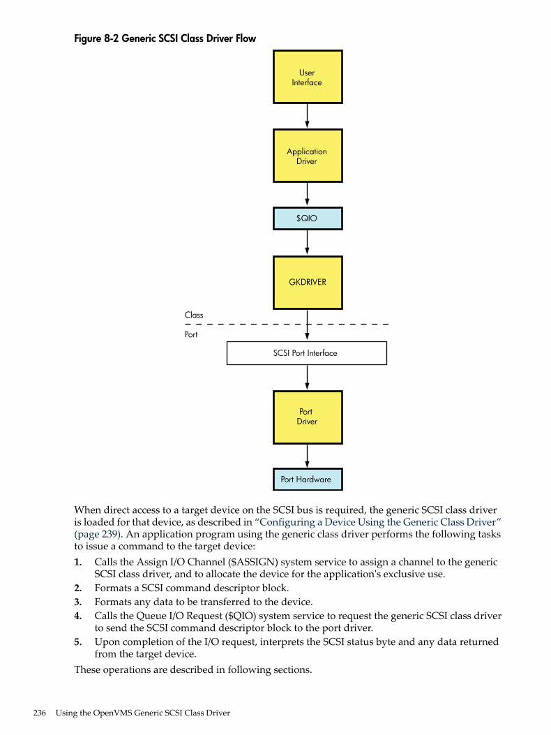
Figure 8-2 Generic SCSI Class Driver Flow
SCSI Port Interface
Class
GKDRIVER
ApplicationDriver
UserInterface
PortDriver
$QIO
Port Hardware
Port
When direct access to a target device on the SCSI bus is required, the generic SCSI class driveris loaded for that device, as described in “Configuring a Device Using the Generic Class Driver”(page 239). An application program using the generic class driver performs the following tasksto issue a command to the target device:1. Calls the Assign I/O Channel ($ASSIGN) system service to assign a channel to the generic
SCSI class driver, and to allocate the device for the application's exclusive use.2. Formats a SCSI command descriptor block.3. Formats any data to be transferred to the device.4. Calls the Queue I/O Request ($QIO) system service to request the generic SCSI class driver
to send the SCSI command descriptor block to the port driver.5. Upon completion of the I/O request, interprets the SCSI status byte and any data returned
from the target device.These operations are described in following sections.
236 Using the OpenVMS Generic SCSI Class Driver

NOTE: Because incorrect or malicious use of the generic SCSI class driver can result in SCSIbus hangs and lead to SCSI bus resets, DIAGNOSE and PHY_IO or LOG_IO privileges arerequired to access the driver. An application program can be designed in such a way as to filteruser I/O requests, which allows nonprivileged users access to some device functions.
8.4 Accessing the OpenVMS Generic SCSI Class DriverInteractive commands and procedure calls can use the OpenVMS generic SCSI class driver toaccess devices on the SCSI bus. However, it is unlikely that a user application would access adevice on the SCSI bus by directly using the $QIO interface of the generic SCSI class driver. Firstof all, any user process directly using the $QIO interface would require DIAGNOSE and PHY_IOor LOG_IO privileges. Under normal circumstances, it would be a system security risk to grantDIAGNOSE and PHY_IO or LOG_IO privileges to many system users. Secondly, it would becumbersome for end users of the device to identify, format, and issue SCSI commands to thedevice. Rather, it would be more efficient to develop an interface that hides these details.A utility program, installed with the DIAGNOSE and PHY_IO or LOG_IO privileges, can providenonprivileged users with a command-line interface to a SCSI device. The utility translatesinteractive commands provided by the user into the appropriate set of SCSI commands andsends them to the device using the $QIO interface provided by the generic SCSI class driver. Theutility checks user commands to ensure that only valid SCSI commands are sent to the device.For information about installing images with privileges, see the HP OpenVMS System Manager'sManual and the HP OpenVMS System Management Utilities Reference Manual .A privileged shareable image can provide system applications with a procedure interface to aSCSI device. The image contains a set of procedures that translate operations specified by thecaller into the appropriate set of SCSI commands. The SCSI commands are sent to the devicethrough the $QIO interface of the generic SCSI class driver. The privileged shareable imagechecks its caller's parameters to ensure that only valid SCSI commands are sent to the device.For information about creating shareable images, see the HP OpenVMS Programming Conceptsmanual.
8.5 SCSI Port Features Under Application ControlThe standard OpenVMS SCSI port driver provides mechanisms by which the generic SCSI classdriver can control the nature of data transfers and command transmission across the SCSI bus.An application uses the $QIO interface to tailor these mechanisms to the specific device it supports.Among the features under application program control are the following:• Data transfer mode• Disconnection and reselection• Command retry• Command time-outsThe following sections discuss these features.
8.5.1 Setting the Data Transfer ModeThe SCSI bus defines two data transfer modes, asynchronous and synchronous. In asynchronousmode, for each REQ from a target there is an ACK from the host prior to the next REQ from thetarget. Synchronous mode allows higher data transfer rates by allowing a pipelined data transfermechanism where, for short bursts (defined by the REQ-ACK offset), the target can pipeline datato an initiator without waiting for the initiator to respond.Whether or not a port or a target device allows synchronous data transfers, it is harmless for theprogram to set up the connection to use such transfers. If synchronous mode is not supported,the port driver automatically uses asynchronous mode.
8.4 Accessing the OpenVMS Generic SCSI Class Driver 237

For example, to use synchronous mode in a transfer, a programmer using the generic SCSI classdriver must ensure that both the SCSI port and the SCSI device involved in the transfer supportsynchronous mode. The SCSI port of the VAXstation 3520/3540 system allows both synchronousand asynchronous transfers, whereas that of OpenVMS 3100 systems supports only asynchronoustransfers.To set up a connection to use synchronous data transfer mode, a program using the generic SCSIclass driver sets the syn bit in the flags field of the generic SCSI descriptor, the address of whichis passed to the driver in the p1 argument to the $QIO request.
8.5.2 Enabling Disconnection and ReselectionThe ANSI SCSI specification defines a disconnection facility that allows a target device to yieldownership of the SCSI bus while seeking or performing other time-consuming operations. Whena target disconnects from the SCSI bus, it sends a sequence of messages to the initiator that causeit to save the state of the I/O transfer in progress. Once this is done, the target releases the SCSIbus. When the target is ready to complete the operation, it reselects the initiator and sends to itanother sequence of messages. This sequence uniquely identifies the target and allows the initiatorto restore the context of the suspended I/O operation.Whether disconnection should be enabled or disabled on a given connection depends on thenature and capabilities of the device involved in the transfer, as well as on the configuration ofthe system. In configurations where there is a slow device present on the SCSI bus, enablingdisconnection on connections that transfer data to the device can increase bus throughput. Bycontrast, systems where most of the I/O activity is directed towards a single device for longintervals can benefit from disabling disconnection. By disabling disconnection when there is nocontention on the SCSI bus, port drivers can increase throughput and decrease the processoroverhead for each I/O request.By default, the OpenVMS class/port interface disables the disconnect facility on a connection.To enable disconnection, an application program using the generic SCSI class driver sets the disbit of the flags field of the generic SCSI descriptor, the address of which is passed to the driverin the p1 argument to the $QIO call.
8.5.3 Disabling Command RetryThe SCSI port driver implements a command retry mechanism, which is enabled on a givenconnection by default.When the command retry mechanism is enabled, the port driver retries up to three times anyI/O operation that fails during the COMMAND, Message, Data, or STATUS phases. For instance,if the port driver detects a parity error during the Data phase, it aborts the I/O operation, logsan error, and retries the I/O operation. It repeats this sequence twice more, if necessary. If theI/O operation completes successfully during a retry attempt, the port driver returns success statusto the class driver. However, if all retry attempts fail, the port driver returns failure status to theclass driver.An application may need to disable the command retry mechanism under certain circumstances.For example, repeated execution of a command on a sequential device may produce differentresults than are intended by a single command request. A tape drive could perform a partialwrite and then repeat the write without resetting the tape position.An application program using the generic SCSI class driver can disable the command retrymechanism by setting the dpr bit of the flags field of the generic SCSI descriptor, the address ofwhich is passed to the driver in the p1 argument to the $QIO request.
238 Using the OpenVMS Generic SCSI Class Driver

8.5.4 Setting Command TimeoutsThe SCSI port driver implements several timeout mechanisms, some governed by the ANSI SCSIspecification and others required by OpenVMS. The time-outs required by OpenVMS includethe following:
DescriptionTimeout
Maximum number of seconds for a target to change the SCSI bus phase or completea data transfer. (This value is also known as the DMA timeout.)Upon sending the last command byte, the port driver waits this many seconds forthe target to change the bus phase lines and assert REQ (indicating a new phase).Or, if the target enters the DATA IN or DATA OUT phase, the transfer must becompleted within this interval.
Phase change timeout
Maximum number of seconds, from the time the initiator receives theDISCONNECT message, for a target to reselect the initiator so that it can proceedwith the disconnected I/O transfer
Disconnect timeout
An application program using the generic SCSI class driver is responsible for maintaining bothof these timeout values. It has the following options:• Accepting a connection's default value. The default value for both timeouts is 20 seconds.• Altering the connection's default value. To modify the default values, the class driver specifies
nonzero values for the phase change timeout and disconnect timeout fields of the genericSCSI descriptor, the address of which is passed to the driver in the p1 argument to the $QIOsystem service call.
8.6 Configuring a Device Using the Generic Class DriverOn VAX systems, the System Generation utility (SYSGEN) loads the generic SCSI class driverinto system virtual memory, creates additional data structures for the device unit, and calls thedriver's controller initialization routine and unit initialization routine. SYSGEN automaticallyloads and autoconfigures the SCSI port driver at system initialization. As part of autoconfiguration,SYSGEN polls each device on each SCSI bus. If the device identifies itself as a direct-access device,direct-access CD-ROM device, or flexible disk device, SYSGEN automatically loads the disk classdriver (DKDRIVER). If the device identifies itself as a sequential-access device, SYSGENautomatically loads the tape class driver (MKDRIVER). If the autoconfiguration facility does notrecognize the type of the SCSI device, it does not load a driver.If a third-party-supplied SCSI device requires that the generic class driver be loaded, it must beconfigured by an explicit SYSGEN CONNECT command, as follows:$ RUN SYS$SYSTEM:SYSGENSYSGEN> CONNECT GKpd0u /NOADAPTER
SYSMAN performs the same functions that SYSGEN performs on VAX systems. If athird-party-supplied SCSI device requires that the generic class driver be loaded, the device mustbe configured by an explicit SYSMAN CONNECT command, as follows:$ RUN SYS$SYSTEM:SYSMANSYSMAN> IO CONNECT GKpd0u /NOADAPTER/DRIVER=SYS$GKDRIVER
On VAX and Alpha systems, GK is the device mnemonic for the generic SCSI class driver(GKDRIVER); p represents the SCSI port ID (for instance, the controller ID A or B ); d representsthe SCSI device ID (a digit from 0 to 7); 0 signifies the digit zero; and u represents the SCSI logicalunit number (a digit from 0 to 7).Multiple devices residing on any SCSI bus in the system can share GKDRIVER as a class driver,as long as a CONNECT command is issued for each target device that requires the driver.Because just one connection can exist through the SCSI port driver to each target, the genericclass driver cannot be used for a target if a different SCSI class driver is already connected to
8.6 Configuring a Device Using the Generic Class Driver 239
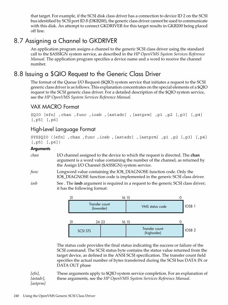
that target. For example, if the SCSI disk class driver has a connection to device ID 2 on the SCSIbus identified by SCSI port IDB (DKB200), the generic class driver cannot be used to communicatewith this disk. An attempt to connect GKDRIVER for this target results in GKB200 being placedoff line.
8.7 Assigning a Channel to GKDRIVERAn application program assigns a channel to the generic SCSI class driver using the standardcall to the $ASSIGN system service, as described in the HP OpenVMS System Services ReferenceManual. The application program specifies a device name and a word to receive the channelnumber.
8.8 Issuing a $QIO Request to the Generic Class DriverThe format of the Queue I/O Request ($QIO) system service that initiates a request to the SCSIgeneric class driver is as follows. This explanation concentrates on the special elements of a $QIOrequest to the SCSI generic class driver. For a detailed description of the $QIO system service,see the HP OpenVMS System Services Reference Manual.
VAX MACRO Format$QIO [efn] ,chan ,func ,iosb ,[astadr] ,[astprm] ,p1 ,p2 [,p3] [,p4][,p5] [,p6]
High-Level Language FormatSYS$QIO ([efn] ,chan ,func ,iosb ,[astadr] ,[astprm] ,p1 ,p2 [,p3] [,p4][,p5] [,p6])
Argumentschan I/O channel assigned to the device to which the request is directed. The chan
argument is a word value containing the number of the channel, as returned bythe Assign I/O Channel ($ASSIGN) system service.
func Longword value containing the IO$_DIAGNOSE function code. Only theIO$_DIAGNOSE function code is implemented in the generic SCSI class driver.
iosb See . The iosb argument is required in a request to the generic SCSI class driver;it has the following format:
31 1516 0
Transfer count(loworder) VMS status code
31 15162324 0
SCSI STS
IOSB 1
IOSB 2Transfer count(highorder)
The status code provides the final status indicating the success or failure of theSCSI command. The SCSI status byte contains the status value returned from thetarget device, as defined in the ANSI SCSI specification. The transfer count fieldspecifies the actual number of bytes transferred during the SCSI bus DATA IN orDATA OUT phase
[efn],[astadr],[astprm]
These arguments apply to $QIO system service completion. For an explanation ofthese arguments, see the HP OpenVMS System Services Reference Manual.
240 Using the OpenVMS Generic SCSI Class Driver

p1 Address of a generic SCSI descriptor of the following format:
31 0
opcode
4
0
flags
8SCSI command address
12
16
20
24
28
32
36
56
SCSI command length
SCSI data address
SCSI pad length
SCSI data length
phase change timeout
disconnect timeout
reserved
p2 Length of the generic SCSI descriptor.Descriptor Fieldsopcode Currently, the only supported opcode is 1, indicating a
pass-through function. Other opcode values are reserved forfuture expansion.
flags Bit map having the following format:
8.8 Issuing a $QIO Request to the Generic Class Driver 241

31 1234 0
reserved dpr syn dis dir
Bits in the flags bit map are defined as follows:
DefinitionField
Direction of transfer.If this bit is set, the target is expected at some time to enter theDATA IN phase to send data to the host. To facilitate this, the portdriver maps the specified data buffer for write access.If this bit is clear, the target is expected at some time to enter theDATA OUT phase to receive data from the host. To facilitate this,the port driver maps the specified data buffer for read access.The generic SCSI class driver ignores thedir flag if either theSCSIdata address or SCSI data length field of the generic SCSIdescriptor is zero.
dir
Enable disconnection.If this bit is set, the target device is allowed to disconnect duringthe execution of the command.If this bit is clear, the target cannot disconnect during the executionof the command.Note that targets that hold on to the bus for long periods of timewithout disconnecting can adversely affect system performance.See “Enabling Disconnection and Reselection” (page 238) foradditional information.
dis
Enable synchronous mode.If this bit is set, the port driver uses synchronous mode for datatransfers, if both the host and target allow this mode of operation.If this bit is clear, or synchronous mode is not supported by eitherthe host or target, the port driver uses asynchronous mode fordata transfers.See “Setting the Data Transfer Mode” (page 237) for additionalinformation.
syn
Disable port retry.If this bit is clear, the port driver retries, up to three times, anycommand that fails with a timeout, bus parity, or invalid phasetransition error.If this bit is set, the port driver does not retry commands for whichit detects failure.See “Disabling Command Retry” (page 238) for additionalinformation.
dpr
SCSI command address Address of a buffer containing a SCSI command.SCSI command length Length of the SCSI command. The maximum length of the SCSI
command is 128 bytes.SCSI data address Address of a data buffer associated with the SCSI command.
If the dir bit is set in the flags field, data is written into this bufferduring the execution of the command. Otherwise, data is readfrom this buffer and sent to the target device.If the SCSI command requires no data to be transferred, then theSCSI data address field should be clear.
242 Using the OpenVMS Generic SCSI Class Driver

SCSI data length Length, in bytes, of the data buffer pointed to by the SCSI dataaddress field. The maximum data buffer size is 65,535 bytes.If the SCSI command requires no data to be transferred, then thisfield should be clear.
SCSI pad length This field is used to accommodate SCSI device classes that requirethat the transfer length be specified in terms of a larger data unitthan the count of bytes expressed in the SCSI data length field.If the total amount of data requested in the SCSI command doesnot match that specified in the SCSI data length field, this fieldmust account for the difference.For example, suppose an application program is using the genericclass driver to read the first 2 bytes of a disk block. The lengthfield in the SCSI READ command contains 1 (indicating onelogical block, or 512 bytes), while the SCSI data length fieldcontains a 2. The SCSI pad length field must contain thedifference, 510 bytes.For most transfers, this field should contain 0. Failure to initializethe SCSI pad length field properly causes port driver timeoutsand SCSI bus resets.
phase change timeout Maximum number of seconds for a target to change the SCSI busphase or complete a data transfer. A value of 0 causes the SCSIport driver's default phase change timeout value of 4 seconds tobe used.See “Setting Command Timeouts” (page 239) for additionalinformation.
disconnect timeout Maximum number of seconds for a target to reselect the initiatorto proceed with a disconnected I/O transfer. A value of 0 causesthe SCSI port driver's default disconnect timeout value of 4seconds to be used.See “Setting Command Timeouts” (page 239) for additionalinformation.
8.8 Issuing a $QIO Request to the Generic Class Driver 243

8.9 Generic SCSI Class Driver Device InformationA call to the Get Device/Volume Information ($GETDVI) system service returns the followinginformation for any device serviced by the generic SCSI class driver. (See the description of the$GETDVI system service in the HP OpenVMS System Services Reference Manual.)$GETDVI returns the following device characteristics when you specify the item codeDVI$_DEVCHAR:
Available deviceDEV$M_AVL
Input deviceDEV$M_IDV
Output deviceDEV$M_ODV
Shareable deviceDEV$M_SHR
Random-access deviceDEV$M_RND
DVI$DEVCLASS returns the device class, which is DC$_MISC; DVI$DEVTYPE returns the devicetype, which is DT$_GENERIC_SCSI.
8.10 Call a Generic SCSI Class DriverExample 8-1 is an application that uses the generic SCSI class driver to send a SCSI INQUIRYcommand to a device.
244 Using the OpenVMS Generic SCSI Class Driver

Example 8-1 Generic SCSI Class Driver Call Example
/*** * © 2009 Hewlett-Packard Development Company, L.P.** Confidential computer software. Valid license from HP and/or its* subsidiaries required for possession, use, or copying.** Consistent with FAR 12.211 and 12.212, Commercial Computer Software,* Computer Software Documentation, and Technical Data for Commercial Items* are licensed to the U.S. Government under vendor's standard commercial* license.** Neither HP nor any of its subsidiaries shall be liable for technical or* editorial errors or omissions contained herein. The information in this* document is provided "as is" without warranty of any kind and is subject* to change without notice. The warranties for HP products are set forth * in the express limited warranty statements accompanying such products. * Nothing herein should be construed as constituting an additional * warranty.**/
#ifdef VAX#module gktest "V01-03"#else#pragma module gktest "V01-03"#endif
/***++** FACILITY: SYS$EXAMPLES**** MODULE DESCRIPTION:**** GKTEST -- Generic SCSI device inquiry example. This program** uses the SCSI generic class driver to send an inquiry command** to a device on the SCSI bus and send the resulting status to** stdout. PHY_IO and DIAGNOSE privileges are needed to run this** program.**
** AUTHORS:**** Hewlett-Packard**** CREATION DATE: 28-Aug-2009 (adapted from previous OpenVMS version)**** DESIGN ISSUES:**** To be appropriately upwardly-compatible, it would be better** that this module use a SCSI descriptor structure definition** from an appropriate header file (something like scsidef.h).** At the time of most recent modification, no such file was** available for OpenVMS.****** MODIFICATION HISTORY:**** X-1 DCP001 28-Aug-2009** Use structure members that are more "type-sensitive".**** X-2 DCP002 11-Sep-2009** Modifications to platform-specific macro names.** X-3 05-Oct-2009** Modify status checking to return proper error code from** $qio.
8.10 Call a Generic SCSI Class Driver 245

**--*/
/***** INCLUDE FILES***/
#include <stdio.h>#include <ctype.h>#include <iodef.h>#include <descrip.h>#include <starlet.h>
/* ** "De-comment" (and if necessary modify) the following if the** appropriate header file becomes available:#include <scsidef.h>*/
/***** MACRO DEFINITIONS***/
#define GK_EFN 0 /* Event flag number */
#define INQUIRY_OPCODE 0x12 /* Operation code for SCSI inquiry */#define INQUIRY_DATA_LENGTH 0x24 /* Length of inquiry buffer */
/*** SCSI definitions:**** Ideally, these definitions should come from a header file provided** with the system. At the time that this example was written and at** the time of last update, no such file was available. For now, we** define right here fields we need from the SCSI descriptor for this** example; this should be replaced with the appropriate #include,** should such a header file become available. The reader should note** that some of the field names and types in that header file may** differ slightly from what's shown here; when and if the header file** becomes available, code which does depend on the names should use** the appropriate header file names. Code which depends on getting** the types right may need to re-cast these members when referencing** them.*/
/* Generic SCSI command descriptor */
struct SCSI$DESC { unsigned int SCSI$L_OPCODE; /* SCSI Operation Code */ unsigned int SCSI$L_FLAGS; /* SCSI Flags Bit Map */ char * SCSI$A_CMD_ADDR; /* ->SCSI command buffer */ unsigned int SCSI$L_CMD_LEN; /* SCSI command length, bytes */ char * SCSI$A_DATA_ADDR; /* ->SCSI data buffer */ unsigned int SCSI$L_DATA_LEN; /* SCSI data length, bytes */ unsigned int SCSI$L_PAD_LEN; /* SCSI pad length, bytes */ unsigned int SCSI$L_PH_CH_TMOUT; /* SCSI phase change timeout, sec */ unsigned int SCSI$L_DISCON_TMOUT; /* SCSI disconnect timeout, sec */ unsigned int SCSI$L_RES_1; /* Reserved */ unsigned int SCSI$L_RES_2; /* Reserved */ unsigned int SCSI$L_RES_3; /* Reserved */ unsigned int SCSI$L_RES_4; /* Reserved */ unsigned int SCSI$L_RES_5; /* Reserved */ unsigned int SCSI$L_RES_6; /* Reserved */ } ;
246 Using the OpenVMS Generic SCSI Class Driver

/* SCSI Input/Output Status Block */
#ifdef __ALPHA#pragma member_alignment save#pragma nomember_alignment#endif
struct SCSI$IOSB { unsigned short int SCSI$W_VMS_STAT; /* VMS status code */ unsigned long int SCSI$L_IOSB_TFR_CNT; /* Actual #bytes transferred */ char SCSI$B_IOSB_FILL_1; unsigned char SCSI$B_IOSB_STS; /* SCSI device status */ };
#ifdef __ALPHA#pragma member_alignment restore#endif
/* SCSI status codes and flag field constants */
#define SCSI$K_GOOD_STATUS 0#define SCSI$K_READ 0X1 /* direction of transfer=read */#define SCSI$V_FL_ENAB_DIS 1 /* enable disconnects */#define SCSI$K_FL_ENAB_DIS 0X2 /* enable disconnects */
/* end of SCSI definitions */
/* data declarations */
char scsi_status, inquiry_command[6] = {INQUIRY_OPCODE, 0, 0, 0, INQUIRY_DATA_LENGTH, 0}, inquiry_data[INQUIRY_DATA_LENGTH], gk_device[] = {"GKA0"};
main ()
{
unsigned short int gk_chan, transfer_length; int i, status;
/* Set up the descriptor with the SCSI information to be sent to the target */
struct SCSI$DESC gk_desc = { 1, /* Pass-through - the only code defined */ SCSI$K_READ|SCSI$K_FL_ENAB_DIS, /* flags */ &inquiry_command[0], /* command addr */ 6, /* command length*/ &inquiry_data[0], /* data addr */ INQUIRY_DATA_LENGTH, /* data length */ 0, /* pad length */ 180, /* phase timeout */ 60, /* disconnect timeout */ 0, 0, 0, 0, 0, 0 }; /* reserved */
struct SCSI$IOSB gk_iosb ;
$DESCRIPTOR (gk_device_desc, gk_device);
/* Assign the device channel */ status = sys$assign ( &gk_device_desc, &gk_chan, 0, 0); if (!(status & 1)) { printf ("Unable to assign channel to %s", &gk_device[0]); sys$exit (status);
8.10 Call a Generic SCSI Class Driver 247

}
/* Issue the QIO to send the inquiry command and receive the inquiry data */
status = sys$qiow ( GK_EFN, gk_chan, IO$_DIAGNOSE, &gk_iosb, 0, 0, &gk_desc, 15*4, 0, 0, 0, 0);
/* Check the various returned status values */ if (!(status & 1)) sys$exit (status);
/* Was VMS Status OK from QIO? */
if (!(gk_iosb.SCSI$W_VMS_STAT & 1)) sys$exit (gk_iosb.SCSI$W_VMS_STAT);
/* Yes, was SCSI Status OK from QIO? */
if (gk_iosb.SCSI$B_IOSB_STS != SCSI$K_GOOD_STATUS) { printf ("Bad SCSI status returned: %02.2x\n", gk_iosb.SCSI$B_IOSB_STS); sys$exit (1); }
/* The command succeeded. Display the SCSI data returned from the target */
transfer_length = gk_iosb.SCSI$L_IOSB_TFR_CNT; printf ("SCSI inquiry data returned %lu bytes of data: ", transfer_length); for (i=0; i<transfer_length; i++) { if (isprint (inquiry_data[i])) printf ("%c", inquiry_data[i]); else printf ("."); } printf ("\n");}
248 Using the OpenVMS Generic SCSI Class Driver

9 Local Area Network (LAN) Device DriversThis chapter describes the use of LAN drivers that support the LAN devices listed in the SoftwareProduct Description for the OpenVMS Operating System (SPD 82.35.xx). Most of the LAN devicesare described here, but see the Software Product Description for the OpenVMS Operating Systemfor the definitive list of supported devices.The LAN drivers support two user interfaces or APIs, QIO and VCI (VMS CommunicationsInterface). This chapter describes the QIO interface to the LAN drivers, primarily. But most ofthe QIO functionality applies to the VCI interface as well. And the description of the other featuresand characteristics of the LAN devices and LAN drivers applies equally to either interface.The LAN drivers are composed of a set of LAN common routines that implement the userinterfaces plus a LAN port driver for each different type of LAN device. The LAN drivers comprisethe Data Link layer as defined by the OSI Model defined in “Local Area Network (LAN)Terminology” (page 249).
9.1 Local Area Network (LAN) TerminologyThe following is a list of terms relevant to local area networks:• Ethernet — A network communications technology using coaxial or twisted-pair cable,
originally developed by Intel, Xerox, and Digital. It has a data transmission rate of 10megabits/second. It is characterized by the use of the CSMA/CD network access method. Itis described by the IEEE 802.3 standard. Ethernet is also used as an adjective to describeEthernet characteristics, such as an Ethernet address, or an Ethernet application.
• Fast Ethernet — Ethernet operating at 100 megabits/second over twisted-pair cable ormultimode fiber. Fast Ethernet devices support 10 and 100 megabits/second operation overtwisted-pair media or 100 megabits/second over multimode fiber.
• Gigabit Ethernet — Ethernet operating at 1000 megabits/second over twisted-pair cable ormultimode fiber. Gigabit Ethernet devices support 10, 100, and 1000 megabits/secondoperation over twisted-pair media or 1000 megabits/second over multimode fiber.
• FDDI — Fiber Distributed Data Interface, a token-passing network communicationstechnology characterized by use of a dual ring configuration to improve availability uponfailure of a node or connection. It has a data transmission rate of 100 megabits/second. Itoperates over multimode fiber or twisted-pair cable. It is described by the American NationalStandards Institute (ANSI) standard X3T9.5.
• Token Ring — A token-passing network communications technology characterized by astar topology in most implementations. It has a data transmission rate of 4 or 16megabits/second. It operates over twisted-pair cable. It is described by the IEEE 802.5standard.
• ATM — Asynchronous Transfer Mode, a cell-based network communications technology,where network data is divided into 48-byte chunks and transferred across the network witha 5-byte header that contains addressing and control information. The ATM Forum describesthe communications protocol, and specifies how it is to be used to interoperate with Ethernetnetworks, in the LAN Emulation (LANE) standard. To interoperate with Ethernet, the ATMdevice hardware transparently breaks transmit packets into 48-byte chunks and adds a5-byte header and transmits the cells onto the ATM network. On receive, it transparentlyre-assembles the 48-byte chunks to construct each receive packet.
• IEEE — Institute of Electrical and Electronics Engineers, an organization that, among otheractivities, develops and maintains standards for the computer and electronics industries,including the 802 standards that define local area networking.
• ANSI — American National Standards Institute, an organization that develops and maintainsstandards for the computer and communications industries
9.1 Local Area Network (LAN) Terminology 249

• 802.3 — The IEEE standard for Ethernet network technology, including 802.3u for FastEthernet, and 802.3z for Gigabit Ethernet.
• 802.5 — The IEEE standard for Token Ring network technology.• CSMA/CD — Carrier Sense Multiple Access with Collision Detection, the network access
protocol used on half-duplex Ethernet networks to resolve contention between nodescompeting for access to the network medium.
• NIC — Network Interface Card. Other terms that may be used interchangeably includeAdapter, Controller, Device, Card, Port. LAN On Motherboard (LOM) is a variant wherethe NIC hardware is included on a system board. A multiport adapter consists of multipleadapters on one card, so, for example, a quad Ethernet NIC may be referred to as a 4-portcard. A combo adapter consists of multiple adapters, some Ethernet and some storage, SCSIor Fibre Channel.
• Bus — Data and control paths that connect the functional units of a computer. In relationto LAN devices, it refers to the hardware interface between the CPU and the I/O devices.Each LAN device connects to a particular type of bus, such as PCI, PCI-X, PCI-Express, EISA,ISA, XMI, TurboChannel, each of which typically has multiple slots to accommodate severalI/O devices.
• Duplex — A characteristic of a 2-way communication channel that indicates whether thechannel can allow transmission in both directions at the same time (full-duplex) or not(half-duplex).
• Flow Control — A technique where the flow of data along a communications channel isadjusted to ensure that the receiving side can handle incoming data without loss. Manynetwork applications implement flow control techniques in software. Here, this term refersto the implementation of flow control in hardware independent of the network applicationor protocol, as specified by the IEEE 802.3x standard. The receiver side hardware sendsspecial packets, called pause frames, that asks the transmitting side to stop transmitting fora certain amount of time. When the receiver has caught up, it sends a pause frame with azero time to re-enable the transmitter.
• Packet — A unit of data transmission on the network, also called frame. It consists of aheader, body of data, and a Cyclic Redundancy Check (CRC). The frame may be encapsulatedby additional data needed for the particular network technology. Note that LAN Emulationover ATM imposes packet concepts over the underlying cell-based network technology.
• Jumbo Frames — Oversize Ethernet packets, where the range of sizes on Ethernet is from64-1518 bytes, jumbo frames are packets ranging in size from 1519 to 9216 bytes dependingon the hardware and software implementation.
• Link Up/Down — Network connection state, for Ethernet devices. Most Ethernet devicesthat connect to twisted-pair cables have the ability to detect if an active link connectionexists. When both ends of the network connection can detect a valid connection, the link isconsidered to be 'up' and the Ethernet device is capable of using the network channel totransmit and receive packets. When the Ethernet device cannot detect a valid connection,the link is considered 'down' and the device will not transmit or receive over the networkcommunications path.
• Ring Available/Unavailable — Network connection state, for FDDI, Token Ring, or ATMdevices.
• Open Systems Interconnect (OSI) Model — Defines the following seven layers in a networkingframework:— (7) Application Layer— (6) Presentation Layer— (5) Session Layer— (4) Transport Layer— (3) Network Layer
250 Local Area Network (LAN) Device Drivers

— (2) Data Link Layer— (1) Physical Layer
• Port — One end of a communications channel, or the channel itself. When correlated to theOSI Model, port may refer to a communications channel at various layers. At the physicallayer, a port is a LAN device, so a quad Ethernet device is said to be a 4-port card. At thedata link layer, the LAN drivers allow multiple applications to run on one LAN device. Eachapplication will have opened a port to the LAN driver. At the application layer, an applicationmay allow multiple ports to be opened to it, with the application itself doing the multiplexingof the ports through itself to the underlying network. An example of this would be a networkapplication written to send and receive data over a TCP/IP port.In this chapter, applications open a port to the LAN driver to communicate over a particularLAN device. In OpenVMS terms, opening a port is done by assigning a channel.
• User — Refers to the application that has opened a port to the LAN driver. A LAN devicemay be described as having a number of different users. Each user would have opened aport to the LAN device. Examples of users are LAT, TCP/IP, DECnet, Clusters (NISCA).In this chapter, the terms application and user may be used interchangeably.
9.2 Supported LAN DevicesTable 9-1 and Table 9-2 show the LAN devices supported by the OpenVMS Integrity serveroperating system. Table 9-2 lists additional information for the devices listed in Table 9-1. Mostof the LAN devices are described here, but see the Software Product Description for the OpenVMSOperating System (SPD 82.35.xx) for the definitive list of supported devices.
Table 9-1 Supported OpenVMS Integrity server Systems LAN Devices, Part 1
OpenVMS Device TypeDECnetName
OpenVMSName
Device NameI/O BusMedium TypeMedium
DT$_EW_DE500EWAEWA5230APCI100BaseTXEthernet
DT$_EW_DE500EWAEWA5506BPCI4x100BaseTXEthernet
DT$_EI_82559EWAEW82559 (LOM)PCI100BaseTXEthernet
DT$_EW_BCM5701EWAEWA6847APCI-X1000BaseSXEthernet
DT$_EW_BCM5701EWAEWA6825APCI-X1000BaseTXEthernet
DT$_EI_82540EIAEIA7011APCI-X2x1000BaseSXEthernet
DT$_EI_82540EIAEIA7012APCI-X2x1000BaseTXEthernet
DT$_EI_82540EIAEIIntel 82546(LOM)
PCI-X1000BaseTXEthernet
DT$_EW_BCM5703EWAEWAB352APCI-X1000BaseSXEthernet
DT$_EW_BCM5703EWAEWA9782APCI-X1000BaseSXEthernet
DT$_EW_BCM5703EWAEWA9784APCI-X1000BaseTXEthernet
DT$_EW_BCM5703EWAEWAB290APCI-X1000BaseTXEthernet
DT$_EW_BCM5704EWAEWAB465APCI-X2x1000BaseTXEthernet
DT$_EW_BCM5701EWAEWBCM5701(LOM)
PCI1000BaseTXEthernet
DT$_EI_82540EIAEIAD337APCI-e1000BaseTEthernet
DT$_EI_82540EIAEIAD338APCI-e1000BaseSXEthernet
DT$_EI_82540EIAEIAD339APCI-e1000BaseTEthernet
9.2 Supported LAN Devices 251

Table 9-1 Supported OpenVMS Integrity server Systems LAN Devices, Part 1 (continued)
OpenVMS Device TypeDECnetName
OpenVMSName
Device NameI/O BusMedium TypeMedium
DT$_EI_82540EIAEINC360MPCI-e2-p 1Gb MezzEthernet
DT$_EI_82540EIAEINC364MPCI-e4-p GbE MezzEthernet
Table 9-2 Supported OpenVMS Integrity server Systems LAN Devices, Part 2
Driver NameOpenVMSVersion
OpenVMS Device TypeDevice
SYS$EWDRIVER_DE500BA.EXEV8.2DT$_EW_DE500A5230A
SYS$EWDRIVER_DE500BA.EXEV8.2DT$_EW_DE500A5506B
SYS$EIDRIVER.EXEV8.2DT$_EI_8255982559 (LOM)
SYS$EW5700.EXEV8.2DT$_EW_BCM5701A6847A
SYS$EW5700.EXEV8.2DT$_EW_BCM5701A6825A
SYS$EI1000.EXEV8.2DT$_EI_82540A7011A
SYS$EI1000.EXEV8.2DT$_EI_82540A7012A
SYS$EI1000.EXEV8.2DT$_EI_82540Intel 82546 (LOM)
SYS$EI1000.EXEV8.2DT$_EI_82540AB352A
SYS$EW5700.EXEV8.2DT$_EW_BCM5703A9782A
SYS$EW5700.EXEV8.2DT$_EW_BCM5703A9784A
SYS$EW5700.EXEV8.2DT$_EW_BCM5703AB290A
SYS$EW5700.EXEV8.2DT$_EW_BCM5703AB465A
SYS$EW5700.EXEV8.2DT$_EW_BCM5701BCM5701 (LOM)
SYS$EW5700.EXEV8.2DT$_EW_BCM5703BCM5703 (LOM)
SYS$EW5700.EXEV8.2DT$_EW_BCM5704BCM5704 (LOM)
SYS$EI1000.EXEV8.2DT$_EI_82540AB545A
SYS$EI1000.EXEV8.3DT$_EI_82540AD193A
SYS$EI1000.EXEV8.3DT$_EI_82540AD194A
SYS$EI1000.EXEV8.3DT$_EI_82540AD331A
SYS$EI1000.EXEV8.3DT$_EI_82540AD332A
SYS$EI1000.EXEV8.3–1H1DT$_EI_82540AD337A
SYS$EI1000.EXEV8.3DT$_EI_82540AD338A
SYS$EI1000.EXEV8.3DT$_EI_82540AD339A
SYS$EI1000.EXEV8.3DT$_EI_82540NC360M
SYS$EI1000.EXEV8.3DT$_EI_82540NC364M
252 Local Area Network (LAN) Device Drivers

NOTE: A5230A is a DE500-BA equivalent made by Adaptec.A5506B is a DE504-BA equivalent made by IntraServer.A9782A and A9784A are combo Qlogic FibreChannel plus Gigabit Ethernet devices.AB465A is a combo dual Qlogic FibreChannel plus dual Gigabit Ethernet device.AD193A and AD194A are combo Qlogic FibreChannel plus Gigabit Ethernet devices.BCM5701 (LOM) is embedded in the rx2600 and rx8620 systems.BCM5703 (LOM) is embedded in the rx8640 systems.BCM5704 (LOM) is embedded in the rx2660 and BL860c systems.Intel 82546 (LOM) is embedded in the rx1620 and rx2620 systems.100BaseTX devices can do 10BaseT as well.1000BaseTX devices can do 10BaseT and 100BaseTX as well.1000BaseSX is 1000 Mb/s multimode fiber.
9.3 Supported Industry StandardsEthernet drivers support the following features and standards:• Ethernet and IEEE 802.3 packet format• Physical layer identified as 10Base5 (ThickWire), 10Base2 (ThinWire), and 10BaseT
(twisted-pair)• Fast Ethernet physical layer identified as type 100BaseTX• Gigabit Ethernet physical layer identified as 1000BaseT for unshielded twisted-pair (UTP),
1000BaseSX for multimode fiber-optic cables• Gigabit and 10 Gigabit Ethernet implementation of jumbo frames, a de facto industry standard
using a maximum frame size larger than the standard Ethernet maximum of 1518 bytes,generally up to 9018 bytes
FDDI drivers support the following features and standards:• FDDI packet format• Transmission and reception of frame control (FC) priority• ANSI X3.139-1987 FDDI Media Access Control (MAC)• ANSI X3.148-1988 FDDI Physical Layer Protocol (PHY)• ANSI X3.166-1990 FDDI Physical Layer Medium Dependent (PMD)Token Ring drivers support the following features and standards:• IEEE 802.5 packet format• Transmission and reception of priority bits in the access control (AC) field and the frame
control (FC) field• Transmission of source routing header information• Reception of route information (RI)ATM drivers over ELAN support the following features and standards:• Ethernet and IEEE 802.3 packet format• UNI Version 3.0 or 3.1 signaling protocol• LAN emulation (LANE) Version 1.0• Maximum frame sizes of 1516, 4544, and 9234 bytes
9.3 Supported Industry Standards 253

All LAN drivers support the following features:• 802.2 packet format• IEEE 802.2 Class I service including the unnumbered information (UI), exchange identification
(XID) commands and responses, and TEST commands and responses• IEEE 802.2 Class II service may be specified where the functions are provided by the user
application• Six-byte destination and source address fields
9.4 LAN I/O ArchitectureThe OpenVMS LAN software employs a class/port driver architecture to allow LAN applicationsto communicate with other nodes over the LAN device and the network.The class driver is implemented by a collection of execlets known as the LAN common routines.The LAN common routines implement two APIs, QIO and VCI. LAN applications interface tothe LAN device port drivers using these APIs in a common manner across each type of LAN(Ethernet, FDDI, Token Ring, ATM, and Shared Memory). An execlet for each LAN mediumminimizes the differences between them so applications can operate transparently over differenttypes of LANs. LAN over ATM emulates Ethernet and uses the Ethernet LAN common routines.ATM needs a significant amount of additional support code to provide LAN emulation (LANE)and Classical IP (CLIP) support. This support code is located in an ATM execlet. LAN over SharedMemory also emulates Ethernet and uses the Ethernet LAN common routines. No additionalsupport code is needed for Shared Memory.The port drivers operate the LAN hardware, and there is one port driver for each type of LANdevice. Many of the port drivers operate multiple variations of similar hardware. One port driverfor ATM emulates Ethernet and another emulates IP (called Classical IP). The port driver forShared Memory emulates Ethernet. Unlike the port drivers that directly control LAN hardware,the emulated port drivers are pseudo drivers that implement a pseudo hardware interface insoftware.When correlated to the OSI Model, the LAN implementation occupies the bottom two layers,the LAN common routines and LAN port drivers constitute the Data Link Layer, and the LANdevice hardware the Physical Layer and parts of the Data Link Layer. The LAN drivers are oftencalled the data link drivers.
9.4.1 LAN Data StructuresThe OpenVMS I/O subsystem describes devices in terms of a Unit Control Block (UCB). Thereis a UCB for each device, which may be an actual physical device or a pseudo or virtual device.LAN devices include physical devices, NICs located in PCI buses, for example; and virtualdevices, a shared memory emulated Ethernet device, an ATM emulated LAN device, a LANFailover device, or a VLAN device. The LAN drivers define an extension to the standard VMSUCB that includes additional fields needed to provide LAN context.When a LAN application wants to use a LAN device, it assigns a channel (opens a port) to theUCB associated with the LAN device. When this occurs, the VMS I/O subsystem makes a copyof the device UCB and associates the channel with this cloned UCB. Then the application canactivate the channel by specifying the desired characteristics of the channel, such as protocoltype and what multicast addresses to enable. The unit 0 UCB is called the template UCB. Eachnon-zero UCB represents a channel to the device and contains application-specific channelcharacteristics.Each LAN driver also maintains another structure, the LAN Station Block (LSB), which containsLAN common information as well as device-specific data. For each LAN device there is one LSBand a corresponding unit 0 UCB. The LSB contains device-specific data the would be inappropriateto include in the UCB structures such as device rings and device counters.
254 Local Area Network (LAN) Device Drivers
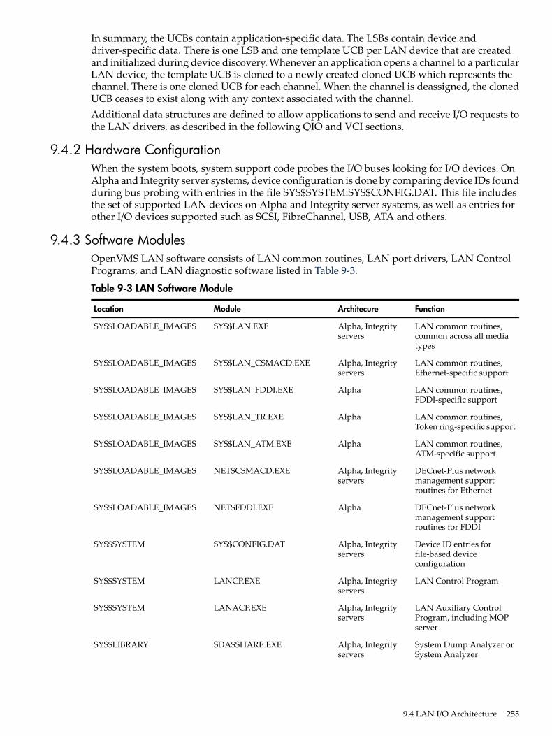
In summary, the UCBs contain application-specific data. The LSBs contain device anddriver-specific data. There is one LSB and one template UCB per LAN device that are createdand initialized during device discovery. Whenever an application opens a channel to a particularLAN device, the template UCB is cloned to a newly created cloned UCB which represents thechannel. There is one cloned UCB for each channel. When the channel is deassigned, the clonedUCB ceases to exist along with any context associated with the channel.Additional data structures are defined to allow applications to send and receive I/O requests tothe LAN drivers, as described in the following QIO and VCI sections.
9.4.2 Hardware ConfigurationWhen the system boots, system support code probes the I/O buses looking for I/O devices. OnAlpha and Integrity server systems, device configuration is done by comparing device IDs foundduring bus probing with entries in the file SYS$SYSTEM:SYS$CONFIG.DAT. This file includesthe set of supported LAN devices on Alpha and Integrity server systems, as well as entries forother I/O devices supported such as SCSI, FibreChannel, USB, ATA and others.
9.4.3 Software ModulesOpenVMS LAN software consists of LAN common routines, LAN port drivers, LAN ControlPrograms, and LAN diagnostic software listed in Table 9-3.
Table 9-3 LAN Software Module
FunctionArchitecureModuleLocation
LAN common routines,common across all mediatypes
Alpha, Integrityservers
SYS$LAN.EXESYS$LOADABLE_IMAGES
LAN common routines,Ethernet-specific support
Alpha, Integrityservers
SYS$LAN_CSMACD.EXESYS$LOADABLE_IMAGES
LAN common routines,FDDI-specific support
AlphaSYS$LAN_FDDI.EXESYS$LOADABLE_IMAGES
LAN common routines,Token ring-specific support
AlphaSYS$LAN_TR.EXESYS$LOADABLE_IMAGES
LAN common routines,ATM-specific support
AlphaSYS$LAN_ATM.EXESYS$LOADABLE_IMAGES
DECnet-Plus networkmanagement supportroutines for Ethernet
Alpha, Integrityservers
NET$CSMACD.EXESYS$LOADABLE_IMAGES
DECnet-Plus networkmanagement supportroutines for FDDI
AlphaNET$FDDI.EXESYS$LOADABLE_IMAGES
Device ID entries forfile-based deviceconfiguration
Alpha, Integrityservers
SYS$CONFIG.DATSYS$SYSTEM
LAN Control ProgramAlpha, Integrityservers
LANCP.EXESYS$SYSTEM
LAN Auxiliary ControlProgram, including MOPserver
Alpha, Integrityservers
LANACP.EXESYS$SYSTEM
System Dump Analyzer orSystem Analyzer
Alpha, Integrityservers
SDA$SHARE.EXESYS$LIBRARY
9.4 LAN I/O Architecture 255

Table 9-3 LAN Software Module (continued)
FunctionArchitecureModuleLocation
SDA extension for LANdrivers
Alpha, Integrityservers
LAN$SDA.EXESYS$LIBRARY
LAN port driversAlpha, Integrityservers
LAN port driversSYS$LOADABLE_IMAGES
The NET$ modules are only loaded when DECnet-Plus is configured on the system.SYS$CONFIG.DAT includes LAN devices as well as any other I/O devices. LAN supportrepresents only a small portion of the SDA.EXE and SDA$SHARE.EXE images.On Alpha and Integrity servers, these routines are separate execlets.
9.4.4 Application APIsThe LAN common routines provide two APIs to allow applications to interface to the LANdrivers and ultimately to send and receive data over the network. The APIs allow an applicationto initialize a port (assign a channel), send a packet over the port, receive a packet from the port,and do other management functions such as set port characteristics, obtain port characteristicsand counters, and to shut down the port (deassign the channel).The APIs are:• QIO — An unprivileged interface to the LAN drivers, designed for user mode code.• VCI — A privileged interface to the LAN drivers that runs in kernel mode at IPL 8, designed
to be very efficient.
9.4.4.1 QIO APIThe QIO API is implemented in the LAN common routines to interface between an applicationand the LAN port driver in user mode. The QIO subsystem passes I/O requests from theapplication to the LAN driver. The LAN driver performs the requested I/O and returns statusand data to the application.An application calls SYS$QIO with a function code, function modifiers, and addresses of buffersthat provide any information needed, such as a buffer containing transmit data, transmit headerdata, a buffer to contain receive data and receive header data, and buffers for setmode andsensemode functions. This information is passed to the LAN driver via the P1-P6 QIO parameters.The LAN common routines translate the I/O function in the QIO request to a transmit, receive,sensemode, setmode, or diagnose operation and passes the request on to the LAN port driver.The LAN port driver does the transmit request, retrieves the receive packet, collects sensemodedata, sets characteristics, or does the diagnose function, and passes the results back through theLAN common routines, back through the QIO subsystem, and back to the application.QIO operations do buffered I/O. This, in addition to considerable validation of the QIO request,makes for a robust user mode interface, but less efficient from a performance standpoint thanthe VCI interface.
9.4.4.1.1 QIO Program Operation
The following sequence shows a typical application sequence, to start a port, do transmits andreceives, then shut down a port:1. Use the Assign I/O Channel ($ASSIGN) system service to assign I/O channels to one or more
of the LAN device names and devices specified in ??? through Table 9-3 (page 255). $ASSIGNcreates a new unit control block (UCB), to which the channel for the port is assigned.
2. Start the port with the set mode function and startup function modifier (see “Set ControllerMode” (page 290). You must supply the required P2 buffer parameters listed in Table 9-33.
3. Perform read, write, and sense mode operations as needed.
256 Local Area Network (LAN) Device Drivers
4. Shut down the port with the set mode function and shutdown function modifier (see“Shutdown Controller” (page 299).
5. Use the Deassign I/O Channel ($DASSGN) system service to deassign the I/O channel.The sample programs described in “Local Area Network Programming Examples” (page 311)illustrate a QIO implementation.
9.4.4.2 VCI APIThe VCI API is implemented in the LAN common routines to interface between the applicationand the LAN port driver in kernel mode at IPL 8. The VCI application calls VCI routines in kernelmode at IPL 8. The VCI routines are part of the LAN common routines. There are routines toinitiate a port management request (to start, stop, and change a port) and to initiate a transmitrequest. The VCI application provides routines that the LAN common routines calls for transmit,receive, and port management completion.An applications calls a VCI initiation routine with an I/O request that contains the transmit bufferor pointers to the transmit data, or the port management buffer data.The LAN common routines process the transmit or port management request and passes therequest on to the LAN port driver.The LAN port driver does the transmit request, or sets characteristics, and passes the resultsback through the LAN common routines, and back to the VCI application by calling theapplication's completion routine. When a receive packet arrives, the LAN common routinespasses the receive buffer to the VCI application by calling the application's receive completionroutine. When the application has completed processing the receive data, it returns the receivebuffer to the LAN common routines by calling a return receive buffer routine.VCI operations do direct I/O, avoiding buffer copies in most cases. VCI applications are consideredtrusted applications, so must abide by the VCI specification to gain that trust and to ensuresystem integrity is maintained operating in kernel mode with privileges.
9.4.5 LAN AddressingEach LAN device is identified by a hardware address that is intended to uniquely identify theLAN device and local system as a node on the network. The hardware address is a 48-bit addressknown as a MAC address or Ethernet address.Ethernet addresses are represented by the Ethernet standard as six pairs of hexadecimal digits(six bytes), separated by hyphens (for example, AA-01-23-45-67-FF). The bytes are displayedfrom left to right in the order in which they are transmitted; bits within each byte are transmittedfrom right to left. In this example, byte AA is transmitted first; byte FF is transmitted last. (Seethe description of NMA$C_PCLI_PHA in Table 9-33, “Set Controller Mode” (page 290), for theinternal representation of addresses.)For Token Ring networks, the address is often given in bit-reversed form, called canonical format,separated by colons. For example, AA-01-23-45-67-FF in canonical format is 55:80:C4:A2:E6:FF.Upon application, IEEE assigns a block of addresses to a producer of LAN nodes. Thus, everymanufacturer has a unique set of addresses to use. Normally, one address out of the assignedblock of physical addresses is permanently associated with each device (usually in read-onlymemory). This address is known as the hardware address or MAC address of the device. Eachindividual device has a unique hardware address.
9.4.5.1 Ethernet Address ClassificationsAn Ethernet address can be a physical address of a single node or a multicast address, dependingon the value of the low-order bit of the first byte of the address (this bit is transmitted first).Following are the two types of node addresses:• Physical address—The unique address of a single node on a LAN. The least significant bit
of the first byte of a physical address is 0. (For example, in physical address
9.4 LAN I/O Architecture 257

AA-00-03-00-FC-00, byte AA in binary is 1010 1010, and the value of the low-order bit is 0.)This is also called an individual address or unicast address.
• Multicast address—A multi-destination address of one or more nodes on a given LAN. Theleast significant bit of the first byte of a multicast address is 1. (For example, in the multicastaddress 0B-22-22-22-22-22, byte 0B in binary is 0000 1011, and the value of the low-order bitis 1. This is the first bit of the address as transmitted over the wire.)
9.4.5.2 Selecting an Ethernet Physical AddressThe OpenVMS interface to the LAN controllers allows you to set a physical address of thecontroller. The selection of the physical address of a LAN controller is different for Ethernet andFDDI.For Ethernet, all users of the controller must agree on this address. The first user of the controllerchooses the physical address; any additional users of the controller must specify either the samephysical address, no physical address, or change the address (if allowed). When all channels tothe controller are shut down, the next user to start a channel chooses the physical address. Thecontroller's physical address is always chosen on the first successful startup when there are noactive ports. If the address is not chosen at this time, the controller's hardware address is usedas the physical address.For Ethernet, the Can Change Address parameter allows the physical address to be changedeven though there are active users. If all current users of the controller have set theNMA$C_PCLI_CCA parameter to NMA$C_STATE_ON, then the physical address can bechanged.For FDDI, each port using a controller may specify its own unique physical address. Anycombination of sharing of physical addresses is also allowed across the ports of an FDDI controller.For example, ports A, B, and C may use one unique physical address and ports D and E may useanother unique address.
9.4.5.3 Ethernet Physical and Multicast Address ValuesThe following shows the multicast addresses assigned for use in cross-company communications:.
MeaningValue
BroadcastFF-FF-FF-FF-FF-FF
Loopback assistanceCF-00-00-00-00-00
The following lists the commonly used multicast addresses.
MeaningValue
Dump/load assistanceAB-00-00-01-00-00
Remote consoleAB-00-00-02-00-00
Level 1 and Level 2 routersAB-00-00-03-00-00
All end nodesAB-00-00-04-00-00
Level 2 routers09-00-2B-02-00-00
Reserved for future useAB-00-00-05-00-00 throughAB-00-03-FF-FF-FF
LATAB-00-03-00-00-00
For use by HP customers for their own applicationsAB-00-04-00-00-00 throughAB-00-04-00-FF-FF
258 Local Area Network (LAN) Device Drivers

MeaningValue
Local area VMSclusterAB-00-04-01-00-00 throughAB-00-04-01-FF-FF
Reserved for future useAB-00-04-02-00-00 throughAB-00-04-FF-FF-FF
Bridge management09-00-2B-01-00-00
Bridge hello multicast09-00-2B-01-00-01
9.4.5.4 Token Ring Functional Address MappingExcept for the global broadcast address (FF-FF-FF-FF-FF-FF), Token Ring hardware does notsupport the 802 standard group LAN address mechanism. Instead, it uses functional addresses.Functional addresses are locally administered group addresses (multicast addresses). The firsttwo bytes of the address are always 03-00 (canonical format), and the remaining four bytes containa bit mask that specifies which of the 32 possible combination masks is being described.Because most OpenVMS LAN applications use standard multicast addresses, a mechanism hasbeen designed to map functional addresses to globally and locally administered multicastaddresses. This allows applications to use the same multicast addresses that are used in the otherLAN media.Table 9-4 shows the default mapping used by the OpenVMS Alpha Token Ring drivers:
Table 9-4 Address Mappings of Token Ring Drivers
DescriptionBit-ReversedFunctional AddressMulticast Address
ISO 9542 All End-system NetworkEntities
C0:00:00:00:40:0003-00-00-00-02-0009-00-2B-00-00-04
ISO 9542 All Intermediate SystemNetwork Entities
C0:00:00:00:80:0003-00-00-00-01-0009-00-2B-00-00-05
Loopback AssistanceC0:00:00:10:00:0003-00-00-08-00-00CF-00-00-00-00-00
MOP Dump/LoadC0:00:40:00:00:0003-00-02-00-00-00AB-00-00-01-00-00
MOP Remote ConsoleC0:00:20:00:00:0003-00-04-00-00-00AB-00-00-02-00-00
DNA L1 RoutersC0:00:10:00:00:0003-00-08-00-00-00AB-00-00-03-00-00
DNA L2 RoutersC0:00:10:00:00:0003-00-08-00-00-0009-00-2B-02-00-00
DECnet Phase IV — TRN — All PhaseIV — TRN Routers
C0:00:10:00:00:0003-00-08-00-00-0009-00-2B-02-01-0A
DNA End nodesC0:00:08:00:00:0003-00-10-00-00-00AB-00-00-04-00-00
Phase IV Prime UnknownC0:00:08:00:00:0003-00-10-00-00-0009-00-2B-02-01-0B
PCSA NETBIOS EmulationC0:00:04:00:00:0003-00-20-00-00-0009-00-2B-00-00-07
Local Area Transport (LAT)C0:00:02:00:00:0003-00-40-00-00-0009-00-2B-00-00-0F
LAT Directory Service Solicit (to slave)C0:00:01:00:00:0003-00-80-00-00-0009-00-2B-02-01-04
LAT Directory Service Solicit — XService Class
C0:00:00:40:00:0003-00-00-02-00-0009-00-2B-02-01-07
LASTC0:00:00:20:00:0003-00-00-04-00-0009-00-2B-04-00-00
DNA Naming Service AdvertisementC0:00:00:00:10:0003-00-00-00-08-0009-00-2B-02-01-00
DNA Naming Service SolicitationC0:00:00:00:08:0003-00-00-00-10-0009-00-2B-02-01-01
9.4 LAN I/O Architecture 259
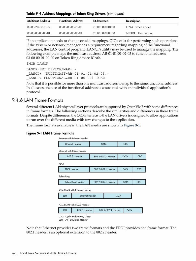
Table 9-4 Address Mappings of Token Ring Drivers (continued)
DescriptionBit-ReversedFunctional AddressMulticast Address
DNA Time ServiceC0:00:00:00:04:0003-00-00-00-20-0009-00-2B-02-01-02
NETBUI EmulationC0:00:00:00:00:8003-00-00-00-00-0103-00-00-00-00-01
If an application needs to change or add mappings, QIOs exist for performing such operations.If the system or network manager has a requirement regarding mapping of the functionaladdresses, the LAN control program (LANCP) utility may be used to manage the mapping. Thefollowing example maps the multicast address AB-01-01-01-02-03 to functional address03-00-00-01-00-00 on Token Ring device ICA0:.$MCR LANCP
LANCP>SET DEVICE/MAP= -_LANCP> (MULTICAST=AB-01-01-01-02-03,-_LANCP> FUNCTIONAL=00-01-00-00) ICA0:
Note that it is possible for more than one multicast address to map to the same functional address.In all cases, the use of the functional address is associated with an individual application'sprotocol.
9.4.6 LAN Frame FormatsSeveral different LAN physical layer protocols are supported by OpenVMS with some differencesin frame formats. The following sections describe the similarities and differences in these frameformats. Despite differences, the QIO interface to the LAN drivers is designed to allow applicationsto run over the different media with few changes to the application.The frame formats available in the LAN media are shown in Figure 9-1.
Figure 9-1 LAN Frame Formats
Ethernet Header DATA CRC
Ethernet with Ethernet header
CRC: Cyclic Redundancy CheckLEH: LAN Emulation Header
802.3 Header CRC
Ethernet with 802.3 header
FDDI Header DATA CRC
FDDI
Token Ring Header DATA CRC
Token Ring
LEH DATA
ATM ELAN with Ethernet Header
ATM ELAN with 802.3 Header
DATA
802.2/802.1 Header
802.2/802.1 Header
802.2/802.1 Header
802.2/802.1 Header
DATA
Ethernet Header
LEH 802.3 Header
Note that Ethernet provides two frame formats and the FDDI provides one frame format. The802.1 header is an optional extension to the 802.2 header.
260 Local Area Network (LAN) Device Drivers
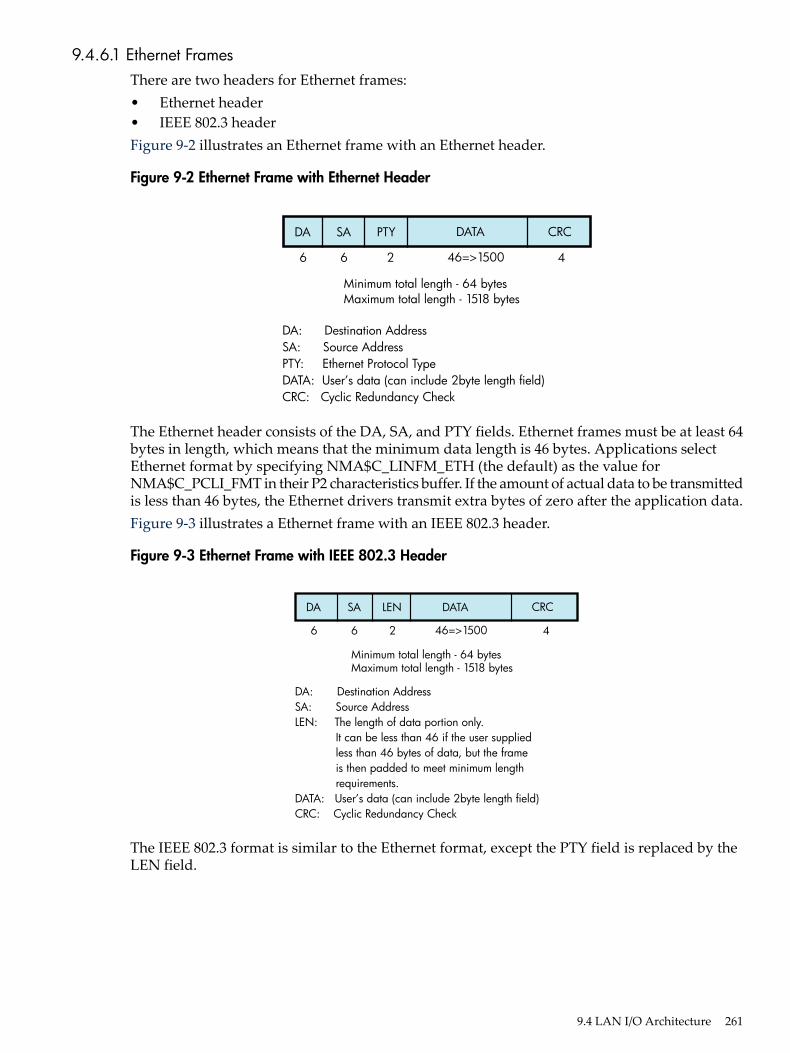
9.4.6.1 Ethernet FramesThere are two headers for Ethernet frames:• Ethernet header• IEEE 802.3 headerFigure 9-2 illustrates an Ethernet frame with an Ethernet header.
Figure 9-2 Ethernet Frame with Ethernet Header
DA SA PTY DATA
Minimum total length - 64 bytesMaximum total length - 1518 bytes
CRC
6 26 446=>1500
DA: Destination AddressSA: Source AddressPTY: Ethernet Protocol TypeDATA: User’s data (can include 2byte length field)CRC: Cyclic Redundancy Check
The Ethernet header consists of the DA, SA, and PTY fields. Ethernet frames must be at least 64bytes in length, which means that the minimum data length is 46 bytes. Applications selectEthernet format by specifying NMA$C_LINFM_ETH (the default) as the value forNMA$C_PCLI_FMT in their P2 characteristics buffer. If the amount of actual data to be transmittedis less than 46 bytes, the Ethernet drivers transmit extra bytes of zero after the application data.Figure 9-3 illustrates a Ethernet frame with an IEEE 802.3 header.
Figure 9-3 Ethernet Frame with IEEE 802.3 Header
DA SA LEN DATA
Minimum total length - 64 bytesMaximum total length - 1518 bytes
CRC
6 26 446=>1500
DA: Destination AddressSA: Source AddressLEN: The length of data portion only.
It can be less than 46 if the user suppliedless than 46 bytes of data, but the frameis then padded to meet minimum lengthrequirements.
DATA: User’s data (can include 2byte length field)CRC: Cyclic Redundancy Check
The IEEE 802.3 format is similar to the Ethernet format, except the PTY field is replaced by theLEN field.
9.4 LAN I/O Architecture 261

9.4.6.2 FDDI FramesFigure 9-4 illustrates the format of FDDI frames.
Figure 9-4 FDDI Frame Format
FC DA SA DATA CRC
1 66 40=>4478
FC: Frame Control contains a “priority” field thatcan be used to determine if the frame originatedon the FDDI or on the Ethernet.
DA: Destination AddressSA: Source AddressDATA: User’s dataCRC: Cyclic Redundancy Check
The FDDI header consists of the FC, DA, and SA fields.
9.4.6.3 Token Ring FramesFigure 9-5 illustrates the format of Token Ring frames.
Figure 9-5 Token Ring Frame Format
AC FC DA SA [RI] DATA CRC
1 6 6 0301 40=>4476
AC: Access Control contains priority for the frame.FC: Frame Control contains the type of frame.DA: Destination AddressSA: Source AddressRI: Optional Routing Information. Only valid with
packets that are source routed.DATA: User’s dataCRC: Cyclic Redundancy Check
262 Local Area Network (LAN) Device Drivers

9.4.6.4 ATM ELAN FramesFigure 9-6 illustrates the format of LAN emulation data frame format for the IEEE 802.3 andEthernet Header.
Figure 9-6 LAN Emulation Data Frame Format with IEEE 802.3/Ethernet Header
LEH DA SA PTY/LEN
*1500 For an 802.3 LAN emulation of size 15164528 For an 802.3 LAN emulation of size 45449218 For an 802.3 LAN emulation of size 9234
DATA
2 66 46=>*2
LEH: LAN Emulator HeaderDA: Destination AddressSA: Source AddressPTY/LEN: For frames with the IEEE 802.3 header,
PTY is the Ethernet Protocol Type. Forframes with the Ethernet header, LEN isthe length of the data portion only. It canbe less than 46 if the user supplied less than46 bytes of data, but the frame is thenpadded to meet minimum requirements.
DATA: User’s data
9.4.6.5 Ethernet (Ethernet Version 2, DIX) Frame FormatThe Ethernet format specifies a two-byte protocol type field followed by an optional length field.The length field is included in transmit packets and expected in receive packets with the PADparameter is enabled. The following sections describe these features.
9.4.6.5.1 Ethernet Protocol Types
Every Ethernet frame has a 2-byte protocol type field. This field is used to determine the port towhich a packet belongs. When an application starts a port, it specifies the protocol type to beused on that port. Packets sent over that port always have the protocol type inserted in the packetheader by the LAN driver, and packets received for that protocol type are delivered to theapplication that owns the port. Valid protocol types are in the range 05-DD through FF-FF.The following lists the cross-company protocol types:
MeaningValue
IP protocol08-00
Address resolution protocol (ARP)08-06
IP protocol Version 6 (IPV6)86-DD
Ethernet Loopback protocol90-00
The following list some commonly used protocol types.
MeaningValue
DNA Dump/load (MOP)60-01
DNA Remote Console (MOP)60-02
9.4 LAN I/O Architecture 263

MeaningValue
DNA Routing60-03
Local Area Transport (LAT)60-04
Diagnostics60-05
Customer use60-06
System Communication Architecture (SCA)60-07
Bridge80-38
DNA Naming Service80-3C
CSMA/CD Encryption80-3D
DNA Time Service80-3E
LAN Traffic Monitor80-3F
NETBIOS Emulator (PCSG)80-40
Local Area System Transport (LAST)80-41
9.4.6.6 802 (IEEE 802.x LLC) Frame FormatThe IEEE 802 packet formats accepted for a port depend on the service enabled on that port. All802 packet formats have an 802.2 header. The service on the port determines the valid values forthe 802.2 fields.When a port is started, the NMA$C_PCLI_SRV parameter in the P2 buffer selects the service onthat port. A value of NMA$C_LINSR_CLI specifies Class I service and a value ofNMA$C_LINSR_USR specifies er-supplied service (the default).
9.4.6.6.1 802 Service Access Point (SAP) Types
Every IEEE 802 frame has a 1-byte Service Access Point (SAP) field. This field identifies wherethe packet came from, the source port on the sending node. And it identifies the destination portfor the packet on the receiving node. When an application starts a port, it specifies the SAP valuethat identifies the port. Packets sent over that port always have SAP value inserted into the SSAPfield in the packet header by the LAN driver, and packets received for the SAP value in the DSAPfield are delivered to the application that owns the port. Also, when transmitting a packet, theapplication specifies the destination SAP value, in addition to the destination address. And whenreceiving a packet, the application is given the source SAP value as well as the source address.The following lists some commonly used SAP values.
MeaningValue
DECnet-V Link State RoutingFE
PathworksF0
9.4.6.6.2 Class I Service Packet Format
For Class I service, only three packet formats are transmitted and received: UI, XID, and TEST.Figure 9-7 shows the 802.2 header format for Class I service.
264 Local Area Network (LAN) Device Drivers

Figure 9-7 Class I Service 802.2 Header
DSAP
SSAP
Size ofField(Bytes)
1
1
1U
The control field for an 802 packet is always an unnumbered control field. The unnumberedcontrol field, which is always 1 byte in length, is passed by the P4 argument of the write QIOand can be one of the following binary values:• UI command (00000011)
This is the unnumbered information command. It is the method used to transmit data fromone user to another and is the most widely used control field value.The UI command can be specified by using NMA$C_CTLVL_UI.
• XID command (101p1111)This is the exchange identification command. It is used to convey information about theport. The “p” bit is the poll bit and can be either 0 or 1. This command can be specified byusing NMA$C_CTLVL_XID for a “0” poll bit or NMA$C_CTLVL_XID_P for a “1” poll bit.
• XID response (101f1111)The XID response is a response to an XID command. The “f” bit is the final bit and matchesthe poll bit from the XID command.
• TEST command (111p0011)The TEST command is used to test a connection. The “p” bit is the poll bit and can be either0 or 1. This command can be specified by using NMA$C_CTLVL_TEST for a “0” poll bit orNMA$C_CTLVL_TEST_P for a “1” poll bit.
• TEST response (111f0011)The TEST response is a response to a TEST command. The “f” bit is the final bit and matchesthe poll bit from the TEST command.
An 802 format port with Class I service is allowed to transmit UI, XID, and TEST commands. An802 format port with Class I service is allowed to receive UI commands and XID and TESTresponses.For more information on these control field values and response messages, see the IEEE 802.2Standard.
9.4.6.6.3 User-Supplied Service Packet Format
The user provides the control field values, which are documented in the IEEE 802.2 Standard.The user-supplied packet format is the generic packet format as specified in the IEEE 802.2Standard. Class I packets (see “Class I Service Packet Format” (page 264) ) are a subset of thisgeneric packet format; therefore, if the control field value of the user-supplied packet is UI, XID,or TEST, the packet is the same as a Class I packet. Note that Class II packets, as defined in theIEEE 802.2 Standard, include the UI, XID, and TEST command/response formats.
9.4.6.6.4 Service Access Point (SAP) Use and Restrictions
The IEEE 802.2 Standard places restrictions on both user SAPs and source SAPs (SSAPs). AllSAPs are 8 bits long. Figure 9-8 shows the format of destination SAPs (DSAPs) and SSAPs.
9.4 LAN I/O Architecture 265

Figure 9-8 DSAP and SSAP Format
DSAP
7 0
DDDDDDDI/G SSAP
7 0
SSSSSSSC/R
Definition of the least significant bit depends on whether the SAP is a source SAP (SSAP) or adestination SAP (DSAP). For a DSAP field, the least significant bit distinguishes group SAPs (bit0 = 1) from individual SAPs (bit 0 = 0). For an SSAP field, the least significant bit distinguishescommands (bit 0 = 0) from responses (bit 0 = 1). Because these two bits are located at the samebit position within the SAP field, a group SAP cannot be used as an SSAP. If this were allowed,a group SAP would be interpreted as an individual SAP with the command/response bit set to1, thus implying a response. The IEEE 802.2 Standard reserves for its own definition all SAPaddresses with the second least significant bit set to 1. You should use these SAP values for theirintended purposes, as defined in the IEEE 802.2 Standard.Up to four group SAPs can be enabled on each 802 port. The group SAPs enabled on a controllerdo not have to be unique for each port; for example, two 802 format ports can have the samegroup SAP enabled. This allows a single packet coming into the controller to be duplicated andpassed to each port on the controller that has the group SAP enabled—assuming the packet hasa DSAP value that is a group SAP. If the received packet has an individual SAP for a DSAP, thepacket goes to, at most, one port.
9.4.6.7 802 Extended (IEEE 802.x LLC/SNAP) Frame FormatThe 802E format uses the 802.2 and 802.1 headers, as shown in Figure 9-9.
Figure 9-9 802 Extended Header
DSAP
SSAP
PID
Size ofField(Bytes)
1
1
1
5
U
For an 802E packet format, the DSAP and SSAP fields are always set to the SNAP SAP (AA hex).The SNAP SAP value is a special SAP value reserved for 802 extended format packets. The SNAPSAP value distinguishes an 802 packet from an 802 extended packet. The only valid control fieldvalue for 802 extended packets is UI (unnumbered information).
9.4.6.7.1 802E PID Types
Every SNAP frame has a 5-byte protocol ID (PID) field. This field is used to determine the portto which a packet belongs. When an application starts a port, the it specifies the PID to be usedon that port. Packets sent over that port always have the PID inserted in the packet header bythe LAN driver, and packets received for that PID are delivered to the application that owns theport.The following lists the cross-company PID values.
MeaningValue
Loopback protocol08-00-2B-90-00
266 Local Area Network (LAN) Device Drivers

The following lists some commonly used PID values.
MeaningValue
Loopback protocol08-00-2B-60-02
DNA Dump/load (MOP)08-00-2B-60-01
DNA Remote Console (MOP)08-00-2B-60-02
DNA Naming Service08-00-2B-80-3C
DNA Time Service08-00-2B-80-3E
Availability Manager (AMDS)08-00-2B-80-48
9.4.7 Packet PaddingThis section describes the PAD parameter NMA$C_PCLI_PAD, which is used only in the Ethernetpacket format.All Ethernet frames must be at least 64 bytes in length. This includes the Ethernet header, theuser data, and the CRC. If the user data, CRC, and Ethernet header together are less than 64bytes, zero padding bytes are inserted between the user data and the CRC to make a 64-bytepacket. This packet padding cannot be turned off.The PAD parameter directs the LAN drivers to place a data-size field in the packet between thestandard header and the user data. If padding is on (NMA$C_STATE_ON is specified), a 2-bytelength field is inserted after the Protocol Type field and before the user data.If the PAD parameter is off (NMA$C_STATE_OFF is specified), Ethernet packets have thefollowing characteristics:• Packets transmitted are padded with null bytes as needed (CSMA/CD only).• Packets transmitted do not include the size field.• The length of user data in the packets received is always between 46 and 1500 bytes (9000
bytes for jumbo frames) for CSMA/CD, and 0 to 4470 for FDDI. For example, if a 10-bytepacket is transmitted, it is received as 46 bytes because the driver cannot determine theamount of user data in the packet—only the amount of user data plus padded null bytes.
If the PAD parameter is on (NMA$C_STATE_ON is specified), Ethernet packets have the followingcharacteristics:• Packets transmitted are padded with null bytes as needed (CSMA/CD only).• Packets transmitted include the size field.• The length of user data in the packets received is always between 0 and 1498 bytes (8998
bytes for jumbo frames) for CSMA/CD, and 0 to 4468 bytes for FDDI. The driver uses thesize field to determine the amount of user data in the packet. The size field is not includedin the data returned to the user.
9.4.8 Protocol Type and PID SharingProtocol types and PIDs are usually nonshareable; however, an application may benefit from ashared protocol implementation. The protocol access parameter (NMA$C_PCLI_ACC) allows aprotocol type or PID to be opened in either of two shareable modes: shared-default(NMA$C_ACC_SHR) and shared-with-destination (NMA$C_ACC_LIM).The LAN drivers also
9.4 LAN I/O Architecture 267

provide the nonshareable exclusive mode (NMA$C_ACC_EXC). (See Table 9-33.) The rules andrequirements for using each mode are as follows:• The exclusive mode is the default if no access mode is supplied as a P2 buffer parameter.
This mode of operation does not allow the protocol to be shared by other users. Any attemptto start up another protocol of the same type results in an error status of SS$_BADPARAM.
• The shared-with-destination mode is a protocol type or PID/destination address pairingthat allows multiple users to share a protocol type or PID and to communicate with a differentnode.For a given shared protocol type or PID, there can be many “shared-with-destination” users;each user communicates with a different destination address. Any attempt to start a portwith a destination address that is in use results in an error status of SS$_BADPARAM.When a “shared-with-destination” user passes the set mode P2 buffer, the buffer mustcontain a destination address in the NMA$C_PCLI_DES parameter. This destination addressis used as the destination address in all messages transmitted, and the user receives messagesonly from this address.
• The shared-default mode is the default user of a shared protocol type or PID. There can beonly one such user for each shared protocol type or PID. A “shared-default” user does nothave to exist if a protocol type or PID is shared, but there can be no more than one such userper shared protocol type or PID.The “shared-default” user receives all messages for the shared protocol type or PID, but notfor any of the “shared-with-destination” users. The “shared-default” user also receives allmessages matching both the shared protocol type or PID and any multicast address enabledby the “shared-default” user.The “shared-default” user can only transmit to multicast addresses and physical addressesthat are not enabled by any of the “shared-with-destination” users sharing the same protocoltype or PID.If there is no “shared-default” user of a protocol type or PID, incoming messages from nodesnot among the “shared-with-destination” users for that protocol type or PID are ignored.
9.5 LAN DevicesThis section describes each LAN device, giving a list of device variants and device characteristics.Some port drivers for these devices provide additional counters and device-specific functionsthat are useful for troubleshooting purposes. This additional data is described in a text file onthe system, SYS$HELP:LAN_COUNTERS_AND_FUNCTIONS.TXT.
9.5.1 Driver-Specific Internal CountersDriver-specific internal counters consist of data maintained by a particular LAN driver that isnot common across all LAN drivers or is not suitable for inclusion in LAN statistics and errorcounters.The LANCP command SHOW DEVICE/INTERNAL_COUNTERS displays the internal countersmaintained by a port driver. Some counters are special debug counters. These are not displayedunless the additional qualifier /DEBUG is specified. Counters that are zero are not displayedunless the additional qualifier /ZERO is specified.The LAN$SDA SDA extension also displays the complete set of internal counters with thecommand LAN INTERNAL/DEVICE=devname.Some Alpha and Integrity servers LAN drivers do not provide a LANCP or LAN$SDA mechanismfor reading these counters. For these drivers, use SDA to display the internal counters using thecommand SHOW LAN/INTERNAL/DEVICE=devname.
268 Local Area Network (LAN) Device Drivers
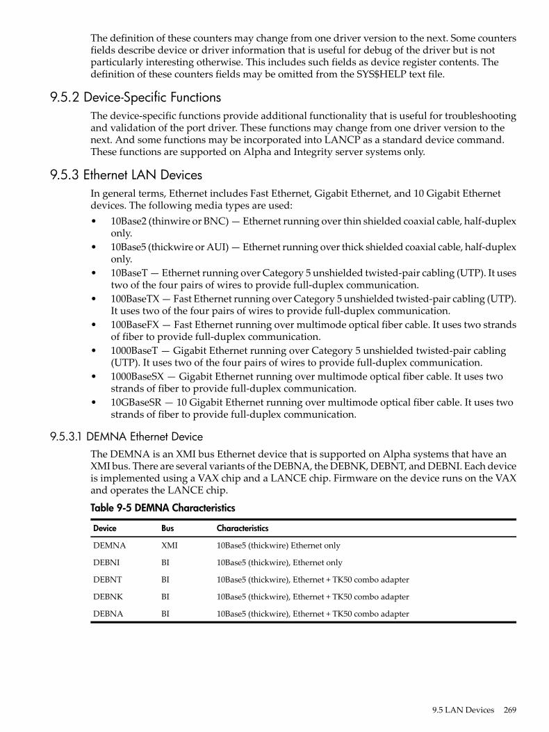
The definition of these counters may change from one driver version to the next. Some countersfields describe device or driver information that is useful for debug of the driver but is notparticularly interesting otherwise. This includes such fields as device register contents. Thedefinition of these counters fields may be omitted from the SYS$HELP text file.
9.5.2 Device-Specific FunctionsThe device-specific functions provide additional functionality that is useful for troubleshootingand validation of the port driver. These functions may change from one driver version to thenext. And some functions may be incorporated into LANCP as a standard device command.These functions are supported on Alpha and Integrity server systems only.
9.5.3 Ethernet LAN DevicesIn general terms, Ethernet includes Fast Ethernet, Gigabit Ethernet, and 10 Gigabit Ethernetdevices. The following media types are used:• 10Base2 (thinwire or BNC) — Ethernet running over thin shielded coaxial cable, half-duplex
only.• 10Base5 (thickwire or AUI) — Ethernet running over thick shielded coaxial cable, half-duplex
only.• 10BaseT — Ethernet running over Category 5 unshielded twisted-pair cabling (UTP). It uses
two of the four pairs of wires to provide full-duplex communication.• 100BaseTX — Fast Ethernet running over Category 5 unshielded twisted-pair cabling (UTP).
It uses two of the four pairs of wires to provide full-duplex communication.• 100BaseFX — Fast Ethernet running over multimode optical fiber cable. It uses two strands
of fiber to provide full-duplex communication.• 1000BaseT — Gigabit Ethernet running over Category 5 unshielded twisted-pair cabling
(UTP). It uses two of the four pairs of wires to provide full-duplex communication.• 1000BaseSX — Gigabit Ethernet running over multimode optical fiber cable. It uses two
strands of fiber to provide full-duplex communication.• 10GBaseSR — 10 Gigabit Ethernet running over multimode optical fiber cable. It uses two
strands of fiber to provide full-duplex communication.
9.5.3.1 DEMNA Ethernet DeviceThe DEMNA is an XMI bus Ethernet device that is supported on Alpha systems that have anXMI bus. There are several variants of the DEBNA, the DEBNK, DEBNT, and DEBNI. Each deviceis implemented using a VAX chip and a LANCE chip. Firmware on the device runs on the VAXand operates the LANCE chip.
Table 9-5 DEMNA Characteristics
CharacteristicsBusDevice
10Base5 (thickwire) Ethernet onlyXMIDEMNA
10Base5 (thickwire), Ethernet onlyBIDEBNI
10Base5 (thickwire), Ethernet + TK50 combo adapterBIDEBNT
10Base5 (thickwire), Ethernet + TK50 combo adapterBIDEBNK
10Base5 (thickwire), Ethernet + TK50 combo adapterBIDEBNA
9.5 LAN Devices 269

9.5.3.2 SGEC/TGEC Ethernet DevicesThe Third Generation Ethernet Controller (TGEC) is embedded in the Alpha-based Digital 4000system.
Table 9-6 SGEC/TGEC Characteristics
CharacteristicsBusDevice
10Base2 (thinwire)AlphaTGEC
9.5.3.3 LANCE Ethernet DevicesThe LANCE is a widely used Ethernet chip used in VAX and Alpha systems. It is used inembedded (LOM) configurations in VAX and Alpha systems, and in QBUS andTURBOchannel-based NICs in VAX and Alpha systems.
Table 9-7 LANCE Characteristics
CharacteristicsBusDevice
LOM, 10Base2 (thinwire)AlphaLANCE
TURBOchannel NIC, 10Base5 (thickwire)AlphaPMAD
Dual TURBOchannel, 10Base5 (thickwire)AlphaDELTA
EISA, 10BaseT (UTP), 10Base2 (thinwire)AlphaDE422
ISA, 10Base2 (thinwire), 10Base5 (thickwire)AlphaDE200
ISA, 10BaseT (UTP)AlphaDE201
ISA, 10Base2 (thinwire), 10BaseT (UTP)AlphaDE202
9.5.3.3.1 LANCE Hardware Configuration
For implementations that include both the 10Base2 and 10Base5 ports, a switch next to the physicalconnectors determines the port selection.The DE422 includes a jumper block on the NIC that selects 10BaseT or 10Base2.The DE20x NICs are configured by a 12-pin DIP switch on the NIC. See the DE20x User Guidefor details.
9.5.3.4 LEMAC Ethernet DevicesThe DE203 and variants are based on the LEMAC chip. These NICs are used on ISA-based Alphaworkstations, primarily the AlphaStation 200 and 400 system.
Table 9-8 LEMAC Characteristics
CharacteristicsDevice
10Base2 (thinwire)DE203
10BaseT (UTP)DE204
10Base2 (thinwire), 10Base5 (thickwire), 10BaseT (UTP)DE205
9.5.3.4.1 ISA LEMAC Hardware Configuration
The DE203 NIC and variants are configured by the console of AlphaStations 200 and 400 systemsusing the 'isacfg' console utility. First, an ISA slot number is chosen, then the IRQ, IO base address,and DMA channel address. Then the slot is configured with the selected characteristics. Whenthe system is reset or power-cycled, the console configures the device as specified.
270 Local Area Network (LAN) Device Drivers

For complete information on using 'isacfg' from your console prompt, see the hardwaredocumentation associated with your system for more information.The ISA slot number is any one of three available slots that is not already in use. The physicallocation of the NIC in the ISA bus is of no consequence as any free slot can be assigned to theNIC.To initialize the 'isacfg' data at the console prompt:>>> isacfg -init
To add a DE205 in slot 1, using IRQ 15:>>> add_de205>>>isacfg -slot 1 -dev 0 -mod -irq 15
To display the ISA configuration data for slot 1:>>>isacfg -slot 1============================================================= handle: DE200-LE etyp: 1 slot: 1 dev: 0 enadev: 1 totdev: 1 iobase0: 300 iobase1: 8000000000000000 iobase2: 8000000000000000 iobase3: 8000000000000000 iobase4: 8000000000000000 iobase5: 8000000000000000 membase0: d0000 memlen0: 10000 membase1: 8000000000000000 memlen1: 8000000000000000 membase2: 8000000000000000 memlen2: 8000000000000000 rombase: 8000000000000000 romlen: 8000000000000000 dma0: 80000000 irq0: f dma1: 80000000 irq1: 80000000 dma2: 80000000 irq2: 80000000 dma3: 80000000 irq3: 80000000 =============================================================
To display the ISA configuration at the console prompt, showing, in this example, a DE203configured in slot 1, and two DW110 Token Ring NICs configured in slots 2 and 3.>>> show config
ISA Slot Device Name Type Enabled BaseAddr IRQ DMA 0 0 MOUSE Embedded Yes 60 12 1 KBD Embedded Yes 60 1 2 COM1 Embedded Yes 3f8 4 3 COM2 Embedded Yes 2f8 3 4 LPT1 Embedded Yes 3bc 7 5 FLOPPY Embedded Yes 3f0 6 2 1 0 DE200-LE Singleport Yes 300 15 2 0 DW11 Singleport Yes a20 10 7 3 0 DW11 Singleport Yes 1a20 5 6
9.5.3.5 3C589 Ethernet DeviceThe 3COM 3C589 PCMCIA NIC is used on the Tadpole AlphaBook notebook system. There aretwo variants:
Table 9-9 3C589 Characteristics
CharacteristicsDevice
10Base2 (thinwire), 10BaseT (UTP)3C589B
10Base2 (thinwire), 10BaseT (UTP)3C589D
9.5 LAN Devices 271

9.5.3.6 Tulip Ethernet and Fast Ethernet DevicesTulip refers to an Ethernet chip designed by Digital Equipment Corporation. It also refers to laterFast Ethernet versions of the chip that maintain a similar programming interface, so can becontrolled by the same driver with few changes.
Table 9-10 Tulip Ethernet and Fast Ethernet Characteristics
CharacteristicsBusDevice
10Base2 (thinwire), 10Base5 (thickwire), 10BaseT (UTP)EISADE425
10BaseT (UTP)PCIDE434
10Base2 (thinwire), 10Base5 (thickwire), 10BaseT (UTP)PCIDE435
Quad DE435PCIDE436
10Base2 (thinwire), 10Base5 (thickwire), 10BaseT (UTP)PCIDE450
10BaseT (UTP), 100BaseTX (UTP), auto-negotiation not supportedPCIDE500-XA
10BaseT (UTP), 100BaseTX (UTP), auto-negotiation supportedPCIDE500-AA
10BaseT (UTP), 100BaseTX (UTP), auto-negotiation supportedPCIDE500-BA
100BaseFX (multimode fiber), auto-negotiation not supportedPCIDE500-FA
Quad DE500-BAPCIDE504-BA
Combo SCSI + DE434PCIP2SE
Combo SCSI + DE500-XAPCIP2SE+
LOM, Digital Personal Workstation, all modes depending on MAU options,auto-negotiation supported
PCI21142
LOM, Alpha Professional Workstation XP900/XP1000, all modes depending onMAU options, auto-negotiation supported
PCI21143
DE500-BA equivalentPCIA5230A
DE504-BA equivalentPCIA5506B
9.5.3.6.1 Tulip Hardware Configuration
The DE425 and DE435 contain a hardware jumper block that selects twisted-pair or AUI as notedon the printed circuit board. AUI includes 10Base2 (thinwire) or 10Base5 (thickwire) and thisselection is made by setting a console environment variable, by a driver autosense algorithm, orby a LANCP command to set the media type, speed, and duplex mode.On Alpha systems prior to OpenVMS Version 7.1, the Tulip driver autosenses the mediaconnection if needed.On Alpha systems starting with OpenVMS Version 7.1, the Tulip driver uses the setting of aconsole environment variable to select the media connection, speed, duplex mode, andauto-negotiation setting. The console environment variable is called EWx0_MODE where x isthe controller letter (for example, A, B, C, ...). The console environment variable is set with thecommand:SET EWx0_MODE media_selection
The media_selection is defined by Table 9-11.
Table 9-11 Tulip Hardware Media Selection
What is selectedMedia selection
10BaseT (UTP) half-duplexTwisted-pair
10BaseT (UTP) full-duplexFull duplex, twisted-pair
272 Local Area Network (LAN) Device Drivers

Table 9-11 Tulip Hardware Media Selection (continued)
What is selectedMedia selection
10Base5 (thickwire)AUI
10Base2 (thinwire)BNC
100BaseTX (UTP) half-duplexFast
100BaseTX (UTP) full-duplexFastFD (full duplex)
Auto-negotiate speed and duplex (UTP)Autonegotiate
During driver initialization, a message is sent to the operator's console to indicate the consoleselection.If a console environment variable has been set with an unsupported media type for the actualdevice, then the driver selects a default media type.An Alpha system console may assign a controller letter to an adapter differently from OpenVMS,because OpenVMS EW devices include Tulip, DEGPA, and Broadcom 5700, but the console onlyrecognizes Tulip devices as EW devices. In this case, you can compare the MAC address listedfor the device at the console SHOW CONFIG and the LANCP SHOW CONFIG commands.On Integrity server systems, there is no console environment variable equivalent, so the defaultsetting is auto-negotiation.On Alpha and Integrity server systems, you can override the console environment variable settingor default setting of auto-negotiation by defining the speed, duplex mode, and auto-negotiationsettings in the LANCP permanent device database.
9.5.3.7 Intel 82559 Fast Ethernet Devices82559 refers to a Fast Ethernet chip designed by Intel Corporation, either the 82558 or the 82559chip. These chips are implemented in PCI bus NICs or a embedded PCI bus on the system board.Both chips support auto-negotiation. Table 9-12 lists the Intel 82559 Fast Ethernet characteristics.
Table 9-12 Intel 82559 Fast Ethernet Characteristics
CharacteristicsDevice
10BaseT (UTP), 100BaseTX (UTP)DE600-AA
Dual DE600-AADE602-AA
Dual DE600-AADE602-BA
Dual DE600-AADE602-BB
Dual DE600-AA daughter card for the DE602DE602-TA
Dual 100BaseFX (multimode fiber) daughter card for the DE602DE602-FA
Combo SCSI + DE600Trifecta
LOM, 10BaseT (UTP), 100BaseTX (UTP)82559ER
LOM, 10BaseT (UTP), 100BaseTX (UTP)82559
9.5.3.7.1 82559 Hardware Configuration
On Alpha systems, the 82559 driver uses the setting of a console environment variable to selectthe media connection, speed, and duplex mode. The console environment variable is calledEIx0_MODE where x is the controller letter (e.g., A, B, C, ...). The console environment variableis set with the command:SET EWx0_MODE media_selection
The media_selection is defined by Table 9-12.
9.5 LAN Devices 273
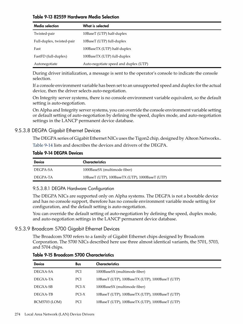
Table 9-13 82559 Hardware Media Selection
What is selectedMedia selection
10BaseT (UTP) half-duplexTwisted-pair
10BaseT (UTP) full-duplexFull-duplex, twisted-pair
100BaseTX (UTP) half-duplexFast
100BaseTX (UTP) full-duplexFastFD (full-duplex)
Auto-negotiate speed and duplex (UTP)Autonegotiate
During driver initialization, a message is sent to the operator's console to indicate the consoleselection.If a console environment variable has been set to an unsupported speed and duplex for the actualdevice, then the driver selects auto-negotiation.On Integrity server systems, there is no console environment variable equivalent, so the defaultsetting is auto-negotiation.On Alpha and Integrity server systems, you can override the console environment variable settingor default setting of auto-negotiation by defining the speed, duplex mode, and auto-negotiationsettings in the LANCP permanent device database.
9.5.3.8 DEGPA Gigabit Ethernet DevicesThe DEGPA series of Gigabit Ethernet NICs uses the Tigon2 chip, designed by Alteon Networks..Table 9-14 lists and describes the devices and drivers of the DEGPA.
Table 9-14 DEGPA Devices
CharacteristicsDevice
1000BaseSX (multimode fiber)DEGPA-SA
10BaseT (UTP), 100BaseTX (UTP), 1000BaseT (UTP)DEGPA-TA
9.5.3.8.1 DEGPA Hardware Configuration
The DEGPA NICs are supported only on Alpha systems. The DEGPA is not a bootable deviceand has no console support, therefore has no console environment variable mode setting forconfiguration, and the default setting is auto-negotiation.You can override the default setting of auto-negotiation by defining the speed, duplex mode,and auto-negotiation settings in the LANCP permanent device database.
9.5.3.9 Broadcom 5700 Gigabit Ethernet DevicesThe Broadcom 5700 refers to a family of Gigabit Ethernet chips designed by BroadcomCorporation. The 5700 NICs described here use three almost identical variants, the 5701, 5703,and 5704 chips.
Table 9-15 Broadcom 5700 Characteristics
CharacteristicsBusDevice
1000BaseSX (multimode fiber)PCIDEGXA-SA
10BaseT (UTP), 100BaseTX (UTP), 1000BaseT (UTP)PCIDEGXA-TA
1000BaseSX (multimode fiber)PCI-XDEGXA-SB
10BaseT (UTP), 100BaseTX (UTP), 1000BaseT (UTP)PCI-XDEGXA-TB
10BaseT (UTP), 100BaseTX (UTP), 1000BaseT (UTP)PCIBCM5703 (LOM)
274 Local Area Network (LAN) Device Drivers

Table 9-15 Broadcom 5700 Characteristics (continued)
CharacteristicsBusDevice
1000BaseSX (multimode fiber)PCIA6847A
10BaseT (UTP), 100BaseTX (UTP), 1000BaseT (UTP)PCIA6825A
10BaseT (UTP), 100BaseTX (UTP), 1000BaseT (UTP)PCI-XAB352A
1000BaseSX (multimode fiber)PCI-XA9782A
10BaseT (UTP), 100BaseTX (UTP), 1000BaseT (UTP)PCI-XA9784A
10BaseT (UTP), 100BaseTX (UTP), 1000BaseT (UTP)PCI-XAB465A
10BaseT (UTP), 100BaseTX (UTP), 1000BaseT (UTP)PCIBCM5701 (LOM)
2x10BaseT (UTP), 10BaseT (UTP), 100BaseTX (UTP), 1000BaseT (UTP)PCIBCM704 (LOM)
2x10BaseT (UTP), 10BaseT (UTP), 100BaseTX (UTP), 1000BaseT (UTP)PCIBCM5709 (LOM)
9.5.3.9.1 5700 Hardware Configuration
On Alpha systems, the 5700 driver uses the setting of a console environment variable to selectthe speed and duplex mode. The console environment variable is called EGx0_MODE where xis the controller letter (e.g., A, B, C, ...). The console environment variable is set with the command:SET EGx0_MODE media_selection
The media_selection is defined by Table 9-16.
Table 9-16 5700 Hardware Media Selection
What is selectedMedia selection
Auto-negotiate speed and duplex (UTP)auto
10BaseT (UTP) half-duplex10mbps
10BaseT (UTP) full-duplex10mbps_full_duplex
100BaseTX (UTP) half-duplex100mbps
100BaseTX (UTP) full-duplex100mbps_full_duplex
1000BaseT (UTP) half-duplex1000mbps
1000BaseT (UTP) full-duplex1000mbps_full_duplex
During driver initialization, a message is sent to the operator's console to indicate the consoleselection.If a console environment variable has been set with an unsupported media type for the actualdevice, then the driver selects a default media type.An Alpha system console may assign a controller letter to an adapter differently from OpenVMS,since OpenVMS EW devices include Tulip, DEGPA, Broadcom 5700, but the console onlyrecognizes 5700 devices as EW devices. In this case you can compare the MAC address listed forthe device at the console SHOW CONFIGURATION and LANCP SHOW CONFIGURATIONcommands.On Integrity server systems, there is no console environment variable equivalent, so the defaultsetting is auto-negotiation.On Alpha and Integrity server systems, you can override the console environment variable settingor default setting of auto-negotiation by defining the speed, duplex mode, and auto-negotiationsettings in the LANCP permanent device database.
9.5 LAN Devices 275

9.5.3.10 Intel 82540 Gigabit Ethernet DevicesThe Intel 82540 refers to a family of Gigabit Ethernet chips designed by Intel Corporation. Thevariants used on these NICs include the 82540, 82546, and 82571 chips.
Table 9-17 Intel 82540 Characteristics
CharacteristicsBusDevice
Dual 1000BaseSX (multimode fiber)PCI-XA7011A
Dual 10BaseT (UTP), 100BaseTX (UTP), 1000BaseT (UTP)PCI-XA7012A
Dual 10BaseT (UTP), 100BaseTX (UTP), 1000BaseT (UTP)PCI-XIntel 82546 (LOM)
Dual 10BaseT (UTP), 100BaseTX (UTP), 1000BaseT (UTP)PCI-XAB352A
9.5.3.10.1 82540 Hardware Configuration
The 82540 devices are supported only on Integrity server systems. The default setting isauto-negotiation.You can override the default setting of auto-negotiation by defining the speed, duplex mode,and auto-negotiation settings in the LANCP permanent device database.
9.5.3.11 Neterion XFRAME 10–Gigabit Ethernet DevicesXFRAME refers to a family of 10–Gigabit Ethernet adapters from Neterion. The variants usedinclude the AB287A and AD385A.
9.5.3.12 Shared Memory Ethernet DeviceThe Shared Memory device is an emulated Ethernet device that uses Galaxy Shared Memory onAlpha systems. Each Galaxy partion is considered a network node. The driver uses sharedmemory to send packet data from one node to another. Applications see the Shared Memorydevice as just another Ethernet device.
9.5.4 FDDI LAN DevicesFDDI devices support the following media• Multimode optical fiber, using two strands of fiber to provide full-duplex communication.• Category 5 unshielded twisted-pair cabling (UTP), using two of the four pairs of wires to
provide full duplex communication.
9.5.4.1 DEMFA FDDI DeviceThe DEMFA is an XMI bus FDDI device that is supported on Alpha systems that have an XMIbus. The DEMFA is a firmware based FDDI controller that uses an Motorola 68000 microprocessorto implement a host interface and the necessary FDDI support functionality.
Table 9-18 DEMFA FDDI Characteristics
CharacteristicsBusDevice
Multimode fiber, 100 megabits/secondXMIDEMFA
9.5.4.2 DEFZA FDDI DeviceThe DEFZA is a TurboChannel FDDI device supported on Alpha TURBOchannel-based systems.
Table 9-19 DEFZA FDDI Characteristics
CharacteristicsBusDevice
Multimode fiber, 100 megabits/secondTurboChannelDEFZA
276 Local Area Network (LAN) Device Drivers

9.5.4.3 PDQ FDDI DevicesThe PDQ chip forms the basis of a family of FDDI devices. These are shown in Table 9-20
Table 9-20 PDQ FDDI Characteristics
CharacteristicBusDevice
Multimode fiber, single attached station (SAS), 100 megabits/secondQBUSDEFQA-SA
Multimode fiber, dual attached station (DAS), 100 megabits/secondQBUSDEFQA-DA
UTP, single attached station (SAS), 100 megabits/secondQBUSDEFQA-SF
UTP, dual attached station (DAS), 100 megabits/secondQBUSDEFQA-DF
Multimode fiber, single attached station (SAS), 100 megabits/secondTurboChannelDEFTA-AA
Multimode fiber, dual attached station (DAS), 100 megabits/secondTurboChannelDEFTA-DA
UTP, single attached station (SAS), 100 megabits/secondTurboChannelDEFTA-UA
UTP, dual attached station (DAS), 100 megabits/secondTurboChannelDEFTA-MA
Multimode fiber, single attached station (SAS), 100 megabits/secondFutureBus+DEFAA-AA
Multimode fiber, dual attached station (DAS), 100 megabits/secondFutureBus+DEFAA-DA
Multimode fiber, single attached station (SAS), 100 megabits/secondEISADEFEA-AA
Multimode fiber, dual attached station (DAS), 100 megabits/secondEISADEFEA-DA
UTP, single attached station (SAS), 100 megabits/secondEISADEFEA-UA
UTP, dual attached station (DAS), 100 megabits/secondEISADEFEA-MA
Multimode fiber, single attached station (SAS), 100 megabits/secondPCIDEFPA-AA
Multimode fiber, dual attached station (DAS), 100 megabits/secondPCIDEFPA-DA
UTP, single attached station (SAS), 100 megabits/secondPCIDEFPA-UA
UTP, dual attached station (DAS), 100 megabits/secondPCIDEFPA-MA
9.5.5 Token Ring LAN DevicesToken Ring devices support the following media types:• STP — Shielded twisted-pair cabling, type 1 STP, using 2 pairs of wires in crossover form.
The cables have DB-9 connectors on them.• UTP — Unshielded twisted-pair cabling, type 3 UTP, using 2 pairs of wires in crossover
form to provide full-duplex communications.
9.5.5.1 TMS380 Token Ring DevicesThe Texas Instruments TMS380 chip forms the basis of a family of Token Ring devices. Theseare shown in Table 9-21.
Table 9-21 TMS380 Token Ring Characteristics
CharacteristicsBusDevice
4/16 megabits/second, STP or UTPTurboChannelDETRA
4/16 megabits/second, STP or UTPEISADW300
4/16 megabits/second, STP or UTP, aka P1392+ISADW110
4/16 megabits/second, STP or UTP, made by Thomas Conrad CorporationPCITC4048
4/16 megabits/second, STP or UTP, made by Racore Computer Products, Inc.PCIM8154
9.5 LAN Devices 277

9.5.5.1.1 ISA TMS380 Hardware Configuration
The DW110 is a bus mastering DMA device on the ISA bus. In addition to setting up the ISA I/Oparameters, you may configure ring speed (4 or 16 megabits/second) and media (UTP or STP).By using LANCP you can also configure ring speed and media during system startup. Example 9-1shows how to configure the OpenVMS software to use the DW110 device.The method for configuring an ISA TMS380 device is to type 'isacfg' at the console prompt (>>>).For complete information on using 'isacfg' from your console prompt, see the hardwaredocumentation associated with your system for more information.The following example illustrates a configuration of:• Slot 4• IRQ 10• DMA channel 7• Base %x4e20• Shielded twisted pair (STP)• Ring speed of 16
Example 9-1 Using the 'isacfg' at Console Prompt with the DW110
>>> isacfg -slot 4 -etyp 1 -ena 1 -irq0 %xa -dmachan0 7 -iobase0 %x4e20 -handle "DW11,STP,16" -mk
The -mk command makes an isacfg entry for an ISA device at slot 4. It is a Single port type ofdevice (-etyp 1). The -handle parameter tells the operating system that this is a DW110 device,that STP media is to be used, and the ring speed is 16.
9.5.6 ATM LAN DevicesAsynchronous transfer mode (ATM) is a cell-oriented switching technology that uses fixed-lengthpackets to carry different types of data.The ATM communicates by first establishing endpoints between two computers with a virtualcircuit (VC) through one or more ATM switches. ATM then provides a physical path for dataflow between the endpoints by either a permanent virtual circuit (PVC), or a switched virtualcircuit (SVC).OpenVMS provides LAN Emulation Client (LEC) support over ATM. The LAN Emulation Clientsoftware supports IEEE/802.3 Emulated LANs, and UNI 3.0 or UNI 3.1 and the followingmaximum frame size (in bytes): 1516, 4544, and 9234.The Emulated LAN driver provides the means for communicating over the LAN ATM. Thedevice type for the Emulated LAN device is DT$_EL_ELAN.The device name for the Emulated LAN is:ELcuwhere c is the controller and u is the unit number (for example, ELA0).ATM devices support the following media types:• Multimode optical fiber, using two strands of fiber to provide full-duplex communication.• Category 5 unshielded twisted-pair cabling (UTP), using two of the four pairs of wires to
provide full-duplex communication.
9.5.6.1 OTTO ATM DevicesOTTO refers to a family of ATM adapters developed by Digital Equipment Corporation. TheTurboChannel adapter is named OTTO. The PCI DGLPB adapter is named OPPO. OTTO andOPPO are programmable logic designs where the driver loads firmware onto the adapters to
278 Local Area Network (LAN) Device Drivers

program the FPGA devices. The DGLPA is a single chip ATM adapter that is a considerablydifferent implementation but lumped into this same category.
Table 9-22 OTTO ATM Characteristics
CharacteristicsBusDevice
155 megabits/second (OC3), multimode fiberTurboChannelDGLTA
155 megabits/second (OC3), multimode fiberPCIDGLPB
155 megabits/second (OC3), UTPPCIDGLPA-UA
155 megabits/second (OC3), multimode fiberPCIDGLPA-FA
The OTTO drivers support ATM LAN Emulation according to the ATM LANE standards, andClassical IP over ATM according to RFC 1577.
9.5.6.2 FORE ATM DevicesThe DAPBA and DAPCA are ATM adapters made by Fore Networks, Inc., now part of MarconiCorporation, Plc.The FORE drivers support ATM LAN Emulation according to the ATM LANE standards.
Table 9-23 FORE ATM Characteristics
CharacteristicsDevice
155 megabits/second (OC3), UTPDAPBA-UA
155 megabits/second (OC3), multimode fiberDAPBA-FA
622 megabits/second (OC12), multimode fiberDAPCA-FA
For each DAPBA, HP recommends increasing the SYSGEN parameter NPAGEVIR by 3000000.For each DAPCA, HP also recommends increasing NPAGEVIR by 6000000. To do this, add theADD_NPAGEVIR parameter to MODPARAMS.DAT and then run AUTOGEN. For example,add the following command to MODPARAMS.DAT on a system with two DAPBAs and oneDAPCA:ADD_NPAGEVIR = 12000000
The following restrictions apply to the DAPBA and DAPCA adapters.• The adapter cannot be located on a PCI bus that is located behind a PCI-to-PCI bridge.
Systems that have this configuration are the following:— HP Personal AlphaWorkstation 600 (MIATA GL)— AlphaStation 1000A (Noritake)— HP Professional Workstation XP1000 (MONET)— AlphaServer 2000 and 2100 (SABLE)
• Classical IP is not supported.
9.5.6.3 Permanent Virtual Circuits (PVC)Permanent Virtual Circuits are set up and torn down by prior arrangement. They are establishedmanually by a user before the sending of any data between endpoints on a network. Some PVCsare defined directly on the switch; others are predefined for use in managing switched virtualcircuits (SVCs).
9.5.6.4 Switched Virtual Circuits (SVC)Switched virtual circuits require no operator interaction to create and manage connectionsbetween endpoints. Software sets up and tears down connections dynamically as they are neededthrough the request of an endpoint.
9.5 LAN Devices 279

9.5.6.5 LAN Emulation over an ATM NetworkLAN emulation over an ATM network network allows existing applications to run essentiallyunchanged while also allowing the applications to run on computers directly connected to theATM network. The LAN emulation hides the underlying ATM network at the media accesscontrol (MAC) layer, which provides device driver interfaces.Table 9-24 shows the four components that make up a LAN emulation over an ATM network.Of the four components, OpenVMS supports only the LAN emulation client (LEC). The remainingcomponents are provided by the ATM switch.
Table 9-24 Components of LAN Emulation over an ATM Network
FunctionComponent
Provides a software driver that runs on a network client and enables LANclients to connect to an ATM network.
LAN emulation client (LEC)
Maintains a mapping between LAN and ATM addresses by resolving LANmedia access control (MAC) addresses with ATM addresses.
LAN emulation server (LES)
Maintains connections with every LAN emulation client (LEC) in the network.For broadcast messages, the BUS sends messages to every attached LEC. TheLECs then forward the message to their respectively attached LANs. Formulticast messages, the BUS sends messages to only those LECs that havedevices in the multicast group. For a LEC that wants to send a regular messagewhose destination MAC address is unknown, the BUS can be used todetermine this address.
Broadcast and Unknown Server (BUS)
Provides a service for LAN emulation clients by helping to determine whichemulated LAN each of the LEC's registered users should join, since each clientcan specify which emulated LAN to join.
LAN emulation configuration server(LECS)
The LEC exists on all ATM-attached computers that participate in the LAN emulationconfiguration. LEC provides the ATM MAC-layer connectionless function that is transparent tothe LAN-type applications. The LEC, LES, and BUS can exist on one ATM-attached computeror on separate computers. The server functions usually reside inside an ATM switch, but can beimplemented on client systems.
9.5.6.6 LAN Emulation TopologyFigure 9-10 shows the topology of a typical emulated LAN over ATM.
280 Local Area Network (LAN) Device Drivers

Figure 9-10 Emulated LAN Topology
ATM/EthernetSwitch
OpenVMSServer
OpenVMSServer
NTWorkstation
UNIX Server
Ethernet
Ethernet
ATM Switch
ATM Switch
Ethernet
...
LECLEC
LEC LEC
LEC
LES BUS
LES BUS
155 Mbps 155 Mbps
155 Mbps 155 Mbps
9.5.6.7 Classical IP Over an ATM NetworkClassical IP (CLIP) implements a data-link level device that has the same semantics as an Ethernetinterface (802.3). This interface is used by a TCP/IP protocol to transmit 802.3 (IEEE Ethernet)frames over an ATM network. The model that OpenVMS follows for exchanging IP datagramsover ATM is based on RFC 1577 (Classical IP over ATM).For information on using LANCP commands to manage Classical IP, see theHPOpenVMSSystemManagement Utilities Reference Manual.
9.5.6.8 Specifying the User to Network Interface (UNI)The ATM software is set to autosense the UNI version by default. Setting bit 3 of the systemparameter, LAN_FLAGS, to 1 enables UNI 3.0 over all ATM adapters. Setting bit 4 of the systemparameter, LAN_FLAGS, to 1 enables UNI 3.1 over all ATM adapters.
9.5.6.9 Enabling SONET/SDHThe ATM drivers have the capability of operating with either synchronous optical network(SONET) or Synchronous Digital Hierarchy (SDH) framing. Setting bit 0 of the system parameter,LAN_FLAGS, to 1 enables SDH framing. Setting bit 0 of the system parameter, LAN_FLAGS, to0 enables SONET framing (default). For this to take affect, the system parameter must be specifiedcorrectly before the ATM adapter driver is loaded.
9.5 LAN Devices 281

9.5.6.10 BootingOpenVMS Alpha does not support ATM adapters as boot devices.
9.5.6.11 Configuring an Emulated LAN (ELAN)The LANCP utility sets up an Emulated LAN (ELAN). If the ELAN is defined in the permanentdatabase, these settings take effect at boot time. To define the commands in the permanentdatabase for specific adapters, you invoke the DEFINE DEVICE commands. Once these commandsdefine the adapters in the permanent database, the ELAN can be started during system startup.You can also invoke the LANCP SET commands to start up an ELAN after the system is booted.The following example shows the DEFINE DEVICE commands that define the adapter in thepermanent database:$ mcr lancpLANCP> define device ela0/elan=createLANCP> define device ela0/elan=(parent=hwa0,type=csmacd,size=1516)LANCP> define device ela0/elan=(descr="An ATM ELAN")LANCP> define device ela0/elan=enable=startupLANCP> list dev ela0/param
Device Characteristics, Permanent Database, for ELA0: Value Characteristic —— ————— HWA0 Parent ATM device "An ATM ELAN" Emulated LAN description 1516 Emulated LAN packet size CSMA/CD Emulated LAN type Yes Emulated LAN enabled for startupLANCP> exit$
The following example shows the SET DEVICE commands required for setting up an ELANwith the desired parameters. Note that some of the commands generate a console message.$ mcr lancpLANCP> set dev ela0/elan=create
%%%%%%%%%%% OPCOM 26-MAR-2001 16:57:12.89 %%%%%%%%%%%Message from user SYSTEM on ALPHA1LANACP LAN ServicesFound LAN device ELA0, hardware address 00-00-00-00-00-00
LANCP> set dev ela0/elan=(parent=hwa0,type=csmacd,size=1516)LANCP> set dev ela0/elan=(descr="An ATM ELAN")LANCP> set dev ela0/elan=enable=startup
%ELDRIVER, LAN Emulation event at 26-MAR-1996 16:57:28.78%ELDRIVER, LAN Emulation startup: Emulated LAN 1 on device ELA0
LANCP> sho dev ela/char
Device Characteristics ELA0: Value Characteristic —— ————— Normal Controller mode External Internal loopback mode CSMA/CD Communication medium 16 Minimum receive buffers 32 Maximum receive buffers No Full duplex enable No Full duplex operational Unspecified Line media 10 Line speed (megabits/second) CSMA/CD Communication medium
282 Local Area Network (LAN) Device Drivers

"HWA0" Parent ATM Device "An ATM ELAN" Emulated LAN Description 3999990000000008002B LAN Emulation Server ATM Address A57E80AA000302FF1300 Enabled Emulated LAN StateLANCP> exit$
For information about using LANCP and system manager commands with qualifiers for LANemulation over ATM networks, see theHPOpenVMSSystemManagementUtilities ReferenceManualand HP OpenVMS System Manager's Manual.
9.6 LAN Device InformationYou can obtain information on controller characteristics by using the Get Device/VolumeInformation ($GETDVI) system service. (See the HPOpenVMS System Services Reference Manual.)$GETDVI returns controller characteristics when you specify the item code DVI$_DEVCHAR.Table 9-25 lists these characteristics, which are defined by the $DEVDEF macro and in the fileSYS$LIBRARY:DEVDEF.H.
Table 9-25 Ethernet Controller Device Characteristics
MeaningCharacteristic
Static Bits (Always Set)
Device is available.DEV$M_AVL
Input device.DEV$M_IDV
Network device.DEV$M_NET
Output device.DEV$M_ODV
DVI$_DEVTYPE and DVI$_DEVCLASS return the device type and device class names, whichare defined by the $DCDEF macro and in the file SYS$LIBRARY:DCDEF.H. The device classname for the LAN Ethernet controllers listed in “Supported LAN Devices” (page 251) is alwaysDC$_SCOM.DVI$_DEVBUFSIZ returns the maximum message size. The maximum send or receive messagesize depends on the packet format and whether padding (NMA$C_PCLI_PAD) is enabled (see“Read” (page 285) and “Write” (page 287) ). DVI$_DEVDEPEND returns the unit and line statusbits and the error summary bits in a longword field as shown in Figure 9-11.
Figure 9-11 DVI$_DEVDEPEND Returns
Not Used Not UsedError Summary Unit and LineStatus
31 1516 78 02324
Table 9-26 lists the status values and their meanings. These values are defined by the $XMDEFmacro. XM$M_STS_ACTIVE is set when the port is started. XM$M_STS_BUFFAIL andXM$M_STS_TIMO are dynamically set and cleared by the LAN driver.
9.6 LAN Device Information 283

Table 9-26 Ethernet Controller Unit and Line Status
MeaningStatus
Port is active.XM$M_STS_ACTIVE
Attempt to allocate a system receive buffer failed.XM$M_STS_BUFFAIL
Timeout occurred.XM$M_STS_TIMO
The error summary bits are set when an error occurs. They are read-only bits. If an error is fatal,the Ethernet port is shut down. Table 9-27 lists the error summary bit values and their meanings.
Table 9-27 Error Summary Bits
MeaningError Summary Bit
Hardware or software error occurred on the controller.XM$M_ERR_FATAL
9.7 LAN Function CodesThe LAN drivers can perform logical, virtual, and physical I/O operations. The basic functionsare read, write, set mode, set characteristics, sense mode, and sense characteristics. Table 9-28lists these functions and their codes. The following sections describe these functions in greaterdetail.
Table 9-28 LAN I/O Functions
FunctionFunction ModifiersType1ArgumentsFunction Code
Read logical block.IO$M_NOWLP1,P2,[P5]IO$_READLBLK2
Read virtual block.IO$M_NOWVP1,P2,[P5]IO$_READVBLK3
Read physical block.IO$M_NOWPP1,P2,[P5]IO$_READPBLK2
Write logical block.IO$M_RESPONSELP1,P2,[P4],P5IO$_WRITELBLK4
Write virtual block.IO$M_RESPONSEVP1,P2,[P4],P5IO$_WRITEVBLK4
Write physical block.IO$M_RESPONSEPP1,P2,[P4],P5IO$_WRITEPBLK4
Set controller characteristicsand controller state forsubsequent operations.
IO$M_CTRL IO$M_STARTUPIO$M_SHUTDOWNIO$M_ATTNASTIO$M_SET_MACIO$M_UPDATE_MAPIO$M_ROUTE
LP1,[P2],P32IO$_SETMODE
Set controller characteristicsand controller state forsubsequent operations.
IO$M_CTRL IO$M_STARTUPIO$M_SHUTDOWNIO$M_ATTNASTIO$M_SET_MACIO$M_UPDATE_MAPIO$M_ROUTE
PP1,[P2],P32IO$_SETCHAR
Sense controller characteristicsand return them in specifiedbuffers.
IO$M_CTRLIO$M_SENSE_MACIO$M_SHOW_MAPIO$M_SHOW_ROUTE
L[P1],[P2]IO$_SENSEMODE
Sense controller characteristicsand return them in specifiedbuffer.
IO$M_CTRLIO$M_SENSE_MACIO$M_SHOW_MAPIO$M_SHOW_ROUTE
P[P1],[P2]IO$_SENSECHAR
284 Local Area Network (LAN) Device Drivers

1 V= virtual, L=logical, P=physical ( There is no functional difference in these operations.)2 On OpenVMS Alpha and Integrity servers , P1 and P5 support 64-bit addresses.3 On OpenVMS Alpha, P1, P4, and P5 support 64-bit address.4 The P1 and P3 arguments are only for attention AST QIOs.
Note that the LAN device drivers do not differentiate among logical, virtual, and physical I/Ofunctions; all are treated identically.
9.7.1 ReadRead functions directly transfer data from a packet received from another port on the Ethernetinto the virtual memory address space of the user process. The operating system provides thefollowing function codes:• IO$_READLBLK—Read logical block• IO$_READVBLK—Read virtual block• IO$_READPBLK—Read physical blockReceived messages are buffered in system memory and then copied to the user's buffer when aread operation is performed.The read functions take the following device- or function-dependent arguments:• P1—The starting virtual address of the buffer that is to receive data. On OpenVMS Alpha
and Integrity server systems, P1 can be a 64-bit address.• P2—The size of the receive buffer in bytes.• P5—The address of a buffer where the LAN driver returns packet header information. This
is an optional argument. The information returned depends on the packet format enabledwith the set mode QIO. The size of the buffer must be 14 bytes for an Ethernet format packet,16 bytes for an IEEE 802 format packet, and 20 bytes for an 802 extended format packet.Note that the information returned is not the entire packet header but the header informationless any length or size fields. The IOSB, if specified, is where the packet length informationis returned. For FDDI, if received access control (RAC) is on, then 1 byte must be added tothese sizes.For Token Ring, this buffer must be at least 54 bytes in length due to a possible variablelength source routing header.If NMA$C_PCLI_PRM (see Table 9-33) is enabled, the P5 buffer must be at least 20 bytesfor Ethernet and 21 bytes for FDDI. Figure 9-12 shows the format of the three buffers. OnOpenVMS Alpha and Integrity server systems, P5 can be a 64-bit address.
9.7 LAN Function Codes 285

Figure 9-12 Read Function P5 Buffer
6 Byte DestinationAddress
8 Byte Source Address
2 Byte Protocol Type
Ethernet Format0
2
4
6
8
10
12
6 Byte DestinationAddress
8 Byte Source Address
1 or 2 Byte CTL Field
0
2
4
6
8
10
12
14SSAP DSAP
IEEE 802 Format
802 Extended Format
6 Byte DestinationAddress
8 Byte Source Address
5 Byte Protocol Identifier
0
2
4
6
8
10
12
14
16
18
SSAP DSAP
1 Byte CTL Field
The P1 and P2 arguments must always be specified; the P5 argument is optional. However, ifP5 is not specified, you will not be able to determine the source of the received message .If the size of the user data in a receive message is larger than the value of the NMA$C_PCLI_BUSparameter, the message is not given to the user, even if there is sufficient space in the user'sreceive buffer.If the size of the user data in a receive message is larger than the size specified in P2 (and lessthan or equal to the value of the NMA$C_PCLI_BUS parameter), the P1 buffer is filled andSS$_DATAOVERUN is returned in the I/O status block.Table 9-29 lists the maximum user data sizes that can be received for Ethernet, FDDI, and TokenRing protocols.
Table 9-29 Maximum User Data Sizes for Ethernet, FDDI, and Token Ring
Token RingFDDIEthernetPacket Format
441844701500Ethernet format without padding
441644681498Ethernet format with padding
286 Local Area Network (LAN) Device Drivers

Table 9-29 Maximum User Data Sizes for Ethernet, FDDI, and Token Ring (continued)
Token RingFDDIEthernetPacket Format
442344751497802 format with 1-byte CTL field
442244741496802 format with 2-byte CTL field
441844701492802E format
Table 9-30 lists the maximum user data sizes that can be received for LAN emulation over ATMprotocol.
Table 9-30 Maximum User Data Sizes for LAN Emulation over ATM
923445441516ATM ELAN size:Packet Format
921845281500Ethernet format without padding
921645261498Ethernet format with padding
921545251497802 format with 1-byte CTL field
921445241496802 format with 2-byte CTL field
921045201492802E format
For 802 format packets, the P5 buffer always contains the DSAP and SSAP in the bytes at offset12 and 13. The next one or two bytes (offsets 14 and 15) following the SSAP contain the controlfield value. For Class I service, the control field value is always 1 byte in length and is alwaysplaced in the byte at offset 14 of this buffer. For user-supplied service, you have to determinethe length of the control field value according to the IEEE 802.2 Standard.For Token Ring, if received access control (RAC) is on, the first byte of the P5 buffer contains theframe control (FC) field.For FDDI, if RAC is on, the first byte of the P5 buffer contains the FC field.The read functions can take the following function modifier:• IO$M_NOW—Complete the read operation immediately with a received message (if no
message is currently available, return a status of SS$_ENDOFFILE in the I/O status block).
9.7.2 WriteWrite functions provide for the direct transfer of data from the virtual memory address space ofthe user process to the communications medium. The operating system provides the followingfunction codes:• IO$_WRITELBLK—Write logical block• IO$_WRITEVBLK—Write virtual block• IO$_WRITEPBLK—Write physical blockTransmitted messages are copied from the buffer of the requesting process to a system bufferfor transmission.The write function takes the following device- or function-dependent arguments:• P1—The starting virtual address of the buffer containing the data to be transmitted. On
OpenVMS Alpha and Integrity server systems, P1 can be a 64-bit address.• P2—The size of the buffer in bytes.• P4—The address of a quadword that points to a buffer that contains the DSAP and CTL
field values (optional). (See “Service Access Point (SAP) Use and Restrictions” (page 265).)The first longword is the buffer length; the second longword is the address of the buffer.
9.7 LAN Function Codes 287

This argument is used only for ports with the 802 packet format. The format of the buffer
is:CTL DSAP
23 78 0
On OpenVMS Alpha and Integrity server systems, P4 can be a 64-bit address.
• P5—The address of a 6-byte buffer that contains the destination address. For FDDI, if XFCis specified as zero on startup, the first byte of the P5 buffer contains the low-order 3 bits ofthe FC field to be transmitted. On OpenVMS Alpha and Integrity server systems, P5 can bea 64-bit address.If the device is in promiscuous mode (NMA$C_PCLI_PRM; see Table 9-33), you must passa larger buffer with additional information positioned after the destination address. ForEthernet packet format, the buffer must be 8 bytes with the 2-byte protocol type followingthe destination address. For 802 packet format, the buffer must be 7 bytes with the 1-bytesource SAP following the destination address. For 802 extended packet format, the buffermust be 11 bytes with the 5-byte protocol identifier following the destination address. TheSource SAP cannot be a group SAP or the SNAP SAP. Figure 9-13 shows the format of theP5 buffer. For FDDI with XFC specified as zero on startup, 1 byte must be added to thesesizes for the FC field.
Figure 9-13 Write Function P5 Buffer
6 Byte DestinationAddress
2 Byte Protocol Type, 1 Byte Source SAP,or 5 Byte Protocol Identifier*
*Only if the channel is in promiscuous mode.
Table 9-31 lists the maximum user data sizes that can be specified by P2 and received for Ethernet,FDDI, and Token Ring protocols.
Table 9-31 Maximum Message Sizes for Ethernet, FDDI, and Token Ring
Token RingFDDIEthernetPacket Format
441844701500Ethernet format without padding
441644681498Ethernet format with padding
442344751497802 format with 1-byte CTL field
442244741496802 format with 2-byte CTL field
441844701492802E format
Table 9-32 lists the maximum user data sizes that can be specified by P2 and received for LANemulation over ATM protocol.
Table 9-32 Maximum Message Sizes for LAN Emulation over ATM
923445441516ATM ELAN size:Packet Format
921845281500Ethernet format without padding
921645261498Ethernet format with padding
921545251497802 format with 1-byte CTL field
288 Local Area Network (LAN) Device Drivers
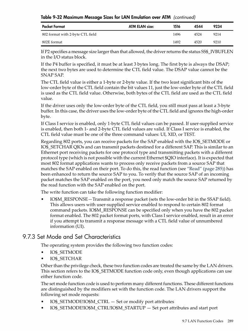
Table 9-32 Maximum Message Sizes for LAN Emulation over ATM (continued)
923445441516ATM ELAN size:Packet Format
921445241496802 format with 2-byte CTL field
921045201492802E format
If P2 specifies a message size larger than that allowed, the driver returns the status SS$_IVBUFLENin the I/O status block.If the P4 buffer is specified, it must be at least 3 bytes long. The first byte is always the DSAP;the next two bytes are used to determine the CTL field value. The DSAP value cannot be theSNAP SAP.The CTL field value is either a 1-byte or 2-byte value. If the two least significant bits of thelow-order byte of the CTL field contain the bit values 11, just the low-order byte of the CTL fieldis used as the CTL field value. Otherwise, both bytes of the CTL field are used as the CTL fieldvalue.If the driver uses only the low-order byte of the CTL field, you still must pass at least a 3-bytebuffer. In this case, the driver uses the low-order byte of the CTL field and ignores the high-orderbyte.If Class I service is enabled, only 1-byte CTL field values can be passed. If user-supplied serviceis enabled, then both 1- and 2-byte CTL field values are valid. If Class I service is enabled, theCTL field value must be one of the three command values: UI, XID, or TEST.Regarding 802 ports, you can receive packets for the SAP enabled with the IO$_SETMODE orIO$_SETCHAR QIOs and can transmit packets destined for a different SAP. This is similar to anEthernet port receiving packets for one protocol type and transmitting packets with a differentprotocol type (which is not possible with the current Ethernet $QIO interface). It is expected thatmost 802 format applications wants to process only receive packets from a source SAP thatmatches the SAP enabled on their port. To do this, the read function (see “Read” (page 285)) hasbeen enhanced to return the source SAP to you. To verify that the source SAP of an incomingpacket matches the SAP enabled on the port, you need only match the source SAP returned bythe read function with the SAP enabled on the port.The write function can take the following function modifier:• IO$M_RESPONSE—Transmit a response packet (sets the low-order bit in the SSAP field).
This allows users with user-supplied service enabled to respond to certain 802 formatcommand packets. IO$M_RESPONSE can be specified only when you have the 802 packetformat enabled. The 802 packet format ports, with Class I service enabled, result in an errorif you attempt to transmit a response message with a CTL field value of unnumberedinformation (UI).
9.7.3 Set Mode and Set CharacteristicsThe operating system provides the following two function codes:• IO$_SETMODE• IO$_SETCHAROther than the privilege check, these two function codes are treated the same by the LAN drivers.This section refers to the IO$_SETMODE function code only, even though applications can useeither function code.The set mode function code is used to perform many different functions. These different functionsare distinguished by the modifiers set with the function code. The LAN drivers support thefollowing set mode requests:• IO$_SETMODE!IO$M_CTRL — Set or modify port attributes• IO$_SETMODE!IO$M_CTRL!IO$M_STARTUP — Set port attributes and start port
9.7 LAN Function Codes 289

• IO$_SETMODE!IO$M_SET_MAC — Set medium attributes• IO$_SETMODE!IO$M_CTRL!IO$M_SHUTDOWN — Shut down port• IO$_SETMODE!IO$M_ATTNAST — Enable attention AST• IO$M_SETMODE!IO$M_UPDATE_MAP — Update functional address mapping table
(Token Ring only)• IO$M_SETMODE!IO$M_ROUTE — Update source routing cache table (Token Ring only)The following sections describe these functions in detail.
9.7.3.1 Set Controller ModeOnce a port is created using the $ASSIGN system service, you can set the port attributes andstart the port using the requests listed in the previous section. Note that in most cases onlyIO$_SETMODE!IO$M_CTRL!IO$M_STARTUP is issued because it sets the port attributes andstarts the port with one request. IO$_SETMODE!IO$M_CTRL is most often used to modify portattributes after the port has been started.If the function modifier IO$M_STARTUP is specified, the LAN port is started. If IO$M_STARTUPis not specified, the specified characteristics are modified.This function takes the following device- or function-dependent argument:• P2—The address of a quadword descriptor for an extended characteristics buffer. The first
longword of the descriptor is the buffer length; the second longword is the address of thebuffer. The P2 argument is optional.
The P2 buffer consists of a series of 6-byte or counted string entries. The first word of each entrycontains the parameter identifier (ID) of an attribute, followed by either a longword that containsone of the (binary) values that can be associated with the parameter ID or a counted string.Counted strings consist of a word that contains the size of the character string followed by thecharacter string. Figure 9-14 shows the format for this buffer.
Figure 9-14 P2 Extended Characteristics Buffer
Parameter ID
Parameter ID
Longword Value or Counted String
Longword Value or Counted String
......
Table 9-33 is an alphabetic listing of the parameter IDs and values that can be specified in the P2buffer. These parameter IDs are applicable to all LAN controllers, except where otherwise noted.The $NMADEF macro defines these values. The $NMADEF macro is included in the macrolibrary SYS$LIBRARY:LIB.MLB. (Table 9-33 lists the parameters that can be used with each ofthe packet formats, and indicates which are required, which are optional, and which generatethe SS$_BADPARAM error.)If the status SS$_BADPARAM is returned in the first word of the I/O status block, the secondlongword contains the parameter ID of the parameter in error.
290 Local Area Network (LAN) Device Drivers

Table 9-33 P2 Attributes
MeaningParameter ID
Protocol access mode. This optional parameter determines the access mode for theprotocol type. NMA$C_PCLI_ACC is valid only for ports using Ethernet packetformat.NMA$C_PCLI_ACC is valid for ports using 802E packet format.One of the following values can be specified:• NMA$C_ACC_EXC — Exclusive mode (default)• NMA$C_ACC_SHR — Shared-default user mode• NMA$C_ACC_LIM — Shared-with-destination mode“Protocol Type and PID Sharing ” (page 267) provides a description of protocol typesharing.“Protocol Type and PID Sharing ” (page 267) provides a description of protocol typePID sharing.NMA$C_PCLI_ACC is passed as a longword value.
NMA$C_PCLI_ACC
Number of receive buffers to preallocate (default = 1). NMA$C_PCLI_BFN can havea maximum value of 255. This optional parameter is specified on a per-port basis.NMA$C_PCLI_BFN is passed as a longword value.NMA$C_PCLI_BFN represents the number of receive messages the LAN driverholds for a port when the port has no read QIOs posted to the driver.
NMA$C_PCLI_BFN
Any message received for this port that is larger than this parameter value isdiscarded.Maximum allowable port receive data size, that is, message length (default = 512bytes). NMA$C_PCLI_BUS can have a maximum value of 9234.This optionalparameter is specified on a per-port basis. It is passed as a longword value.
NMA$C_PCLI_BUS
Can change address. This optional parameter enables applications to start beforeDECnet starts. DECnet may attempt to set the physical address of the controllerwhen it starts. Ethernet devices support only one physical address, and so allapplications that are using the same device must also use the same physical address.If applications that do not use the DECnet address start before DECnet, DECnet isnot able to start on that controller unless the other applications that have alreadystarted have all specified NMA$C_PCLI_CCA to be ON.This parameter is not applicable to FDDI because FDDI devices can run with morethan one physical address; however, no error is returned if this parameter is suppliedfor FDDI devices. The application receives no indication whatsoever that the physicaladdress has changed. This parameter is passed as a longword. One of the followingvalues can be specified:• NMA$C_STATE_ON — The physical address can be changed.• NMA$C_STATE_OFF — The physical address cannot be changed (default).
NMA$C_PCLI_CCA
9.7 LAN Function Codes 291

Table 9-33 P2 Attributes (continued)
MeaningParameter ID
Controller mode. This optional parameter determines whether transmit packetsare to be looped back at the controller. One of the following values can be specified:NMA$C_LINCN_NOR — Normal mode (default)NMA$C_LINCN_LOO —Loopback modeThe only messages looped back are those acceptable to the controller as receivemessages, that is, those messages that possess at least one of the followingcharacteristics:• Matching physical address (see “LAN Addressing” (page 257))• Matching multicast address (see “LAN Addressing” (page 257))• Promiscuous mode (NMA$C_PCLI_PRM) is in the ON state• Destination address is a multicast address and all multicasts are enabled
(NMA$C_PCLI_MLT is in the ON state)NMA$C_PCLI_CON affects all ports on a single controller. It is passed as a longwordvalue.For the DELUA, DEBNA, DEBNI, DEQTA, PMAD, DEMNA, and DESVA, thefollowing list shows the maximum amount of user data that can be looped:Ethernet format without padding — 18 bytesEthernet format with padding — 16 bytes802 format with 1-byte CTL field — 15 bytes802 format with 2-byte CTL field — 14 bytes802 extended format—10 bytesWhen the DEUNA is in loopback mode, the driver always enables echo mode(NMA$C_PCLI_EKO is in the ON state).Not all devices support loopback mode. If normal mode is not specified, the requestis completed with SS$_BADPARAM status.
NMA$C_PCLI_CON1
Cyclic redundancy check (CRC) generation state for transmitted messages (optional).One of the following values can be specified:NMA$C_STATE_ON — Controller generates a CRC (default).NMA$C_STATE_OFF— Controller does not generate a CRC.NMA$C_PCLI_CRC affects all ports on asingle controller. There is no effect onchecking a receive message’s CRC (it is alwayschecked). NMA$C_PCLI_CRC is passed as a longword value.
If NMA$C_PCLI_CRC is turned off, all users of the controller must supply the4-byte CRC value for all messages transmitted. The CRC is passed at the end of theP1 transmit buffer; the additional 4 bytes are included in the size of the P1 buffer.The CRC value is not checked for correctness.For the DEQNA, DELQA, and Token Ring devices, the NMA$C_PCLI_CRCparameter cannot be turned off.For the DEQNA, DELQA, and Token Ring devices, the NMA$C_PCLI_CRCparameter cannot be turned off.Not all devices support user-supplied CRC. If a controller-generated CRC isspecified, the request is completed with SS$_BADPARAM status.
NMA$C_PCLI_CRC1
292 Local Area Network (LAN) Device Drivers

Table 9-33 P2 Attributes (continued)
MeaningParameter ID
Shared protocol destination address. Passed as a counted string that consists of amodifier word (NMA$C_LINMC_SET or NMA$C_LINMC_CLR) followed by a6-byte (48-bit) physical destination address. The size of the counted string mustalways be 8. NMA$C_PCLI_DES only has meaning when protocol access(NMA$C_PCLI_ACC) is defined as shared-with-destination mode (NMA$C_ACC_LIM). The destination address specified must be a physical address—not amulticast address—and it must be unique among all ports sharing the same protocol.NMA$C_PCLI_DES is required when the access mode is defined as‘‘shared-with-destination.’’NMA$C_PCLI_DES should not be specified on a port where the 802 or 802E packetformat is selected (NMA$C_PCLIFMT is set to NMA$C_LIFM_802 orNMA$C_LIFM_802E). For 802 packet format, the concept of shared protocol typeis handled by using group SAPs.NMA$C_PCLI_DES should not be specified on a port where the 802 packet formatis selected (NMA$C_PCLIFMT is set to NMA$C_LIFM_802). For 802 packet format,the concept of shared protocol type is handled by using group SAPs.“Protocol Type and PID Sharing ” (page 267) provides a description of protocol typesharing.“Protocol Type and PID Sharing ” (page 267) provides a description of protocol typePID sharing.
NMA$C_PCLI_DES
Echo mode. Applicable only to the DEUNA device driver.If echo mode is on, transmitted messages are returned to the sender. This optionalparameter controls the condition of the half-duplex bit in the DEUNA mode register.One of the following values can be specified:NMA$C_STATE_OFF — Does not echo transmit messages (default)NMA$C_STATE_ON — Echoes transmit messagesIf NMA$C_STATE_ON is specified, the only transmitted messages echoed are thoseacceptable to the DEUNA as receive messages, that is, those messages that have atleast one of the following characteristics:• Matching physical address (see “LAN Addressing” (page 257))• Matching multicast address (see “LAN Addressing” (page 257))• Promiscuous mode (NMA$C_PCLI_PRM) is in the ON state• Destination address is a multicast address and all multicasts are enabled
(NMA$C_PCLI_MLT is in the ON state)If the DEUNA is placed in loopback mode (NMA$C_LINCN_LOO is specified inthe NMA$C_PCLI_CON parameter), the driver enables echo mode.NMA$C_PCLI_EKO affects all ports on a single controller. It is passed as a longwordvalue.
NMA$C_PCLI_EKO1
Packet format. This optional parameter specifies the packet format as either Ethernet,IEEE 802, or 802 extended. This characteristic is passed as a longword value andaffects single ports on a single controller. One of the following values can bespecified:NMA$C_LINFM_ETH — Ethernet packet format (default) NMA$C_LINFM_802— 802 packet format NMA$C_LINFM_802E — 802 extended packet formatNMA$C_PCLI_PTY, NMA$C_PCLI_ACC, and NMA$C_PCLI_DES should onlybe specified on those ports where the Ethernet packet format (NMA$C_LINFM_ETH) is selected.NMA$C_PCLI_SRV, NMA$C_PCLI_SAP, and NMA$C_PCLI_GSP should only bespecified on those ports where the 802 packet format (NMA$C_LINFM_802) isselected.NMA$C_PCLI_PID should only be specified on those ports where the 802 extendedpacket format (NMA$C_LINFM_802E) is selected.
NMA$C_PCLI_FMT
9.7 LAN Function Codes 293

Table 9-33 P2 Attributes (continued)
MeaningParameter ID
Group SAP. This is an optional parameter if the 802 packet format is selected(NMA$C_PCLIFMT is set to NMA$C_LINFM_802). If the Ethernet or 802 extendedpacket format is selected, NMA$C_PCLI_GSP cannot be specified. Group SAPs canbe shared among multiple ports on the same controller. If the 802 packet format isselected, NMA$C_PCLI_GSP defines up to four 802 group SAPs that are to beenabled for matching incoming packets to complete read operations on this port.By default, no group SAPs are enabled.NMA$C_PCLI_GSP is passed as a longword value and is read as four 8-bit unsignedintegers. Each integer must be either a group SAP or zero. To enable a single groupSAP on a port, you need only specify the group SAP value to be enabled in one ofthe four integers and place a value of zero in the three remaining integers. To disablegroup SAPs on the port, you need only place a value of zero in all four integers andissue the QIO.If this characteristic is correctly specified, any group SAPs that were previouslyenabled on the port are now replaced by the SAPs specified by the current request.
NMA$C_PCLI_GSP
Internal loopback mode. This optional parameter places the device in internalloopback mode (not for the DEUNA, DEQNA, or DELQA devices). One of thefollowing values can be specified:NMA$C_STATE_ON — Internal loopback modeNMA$C_STATE_OFF — Not in internal loopback mode (default)If NMA$C_STATE_ON is specified, the NMA$C_PCLI_CON parameter must bein loopback (NMA$C_LINCN_LOO) mode.When the controller is in loopback mode (generally for testing), it can loop packetsin external loopback or internal loopback. This parameter places the controller inone of these loopback modes. NMA$C_PCLI_ILP is passed as a longword valueand affects all ports on the controller.Not all devices support loopback mode. If NMA$C_STATE_OFF is not specified,the request is completed with SS$_BADPARAM status.
NMA$C_PCLI_ILP1
Multicast address (optional). Passed as a counted string that consists of a modifierword followed by a list of 6-byte (48-bit) multicast addresses. The value specifiedin the modifier word determines whether the addresses are set or cleared. IfNMA$C_LINMC_CAL is specified, all multicast addresses in the list are ignored.The following mode values can be specified in the low byte of the modifier word:NMA$C_LINMC_SET — Set the multicast addresses.NMA$C_LINMC_CLR — Clear the multicast addresses.NMA$C_LINMC_CAL — Clear all multicast addresses.The driver filters all multicast addresses on a per-port basis; therefore, only messagesreceived with the port's physical address or the multicast addresses enabled on theport are used to complete the user's read operations.Note that each LAN controller supports a limited number of multicast addresses.If this limit is exceeded, the LAN driver enables the “accept all multicast” featureon the controller and all multicast packets on the LAN must be filtered by the LANdriver. This may cause a minor performance loss.NMA$C_PCLI_MCA is specified on a per-port basis.
NMA$C_PCLI_MCA
294 Local Area Network (LAN) Device Drivers

Table 9-33 P2 Attributes (continued)
MeaningParameter ID
Multicast address state. This optional parameter instructs the controller hardwarewhether to accept all multicast addresses for this port. One of the following valuescan be specified:NMA$C_STATE_ON — Accept all multicast addresses.NMA$C_STATE_OFF —Do not accept all multicast addresses (default).NMA$C_PCLI_MLT allows you to receive all multicast address packets that alsomatch the port's protocol type, SAP, or protocol identifier.Generally, you enable only your individual set of multicast addresses using theNMA$C_PCLI_MCA parameter, and leave the NMA$C_PCLI_MLT parameter inthe off state.There could be a minor performance loss when the NMA$C_PCLI_MLT parameteris in the ON state because the LAN driver may have to process all multicastaddresses on the medium; the number of multicast addresses on the line determinesthe amount of processing required.The NMA$C_PCLI_MLT parameter is passed as a longword value.
NMA$C_PCLI_MLT
Use message size field on transmit and receive messages (optional). One of thefollowing values can be specified:NMA$C_STATE_ON — Insert message size field (default)NMA$C_STATE_OFF — No size fieldNMA$C_PCLI_PAD affects only the protocol type that issued the set mode request.It is passed as a longword value.On Ethernet, if padding is enabled on Ethernet format packets, the driver adds a2-byte count field to the transmitted data. This field allows short packets (packetsfewer than 46 bytes long) to be received with the proper length returned by thedriver. The minimum Ethernet packet contains 46 bytes of user data. When fewerthan 46 bytes are sent, the packet is padded and the receiver always receives 46bytes of data. When padding is enabled, the maximum message size for transmitor receive operations is 1498 bytes (8998 bytes for jumbo packets) and the minimumis zero bytes. See “Ethernet Protocol Types” (page 263) for additional information.NMA$C_PCLI_PAD should be specified only on a port where the Ethernet packetformat is selected (NMA$C_PCLI_FMT is set to NMA$C_LINFM_ETH).For FDDI, the same 2-byte count field is added; however, because FDDI packetscan be as short as 22 bytes, FDDI transmit requests are never padded.
NMA$C_PCLI_PAD
Physical address (optional). It is passed as a counted string that consists of a modifierword followed by the 48-bit physical address. If the request is to clear the physicaladdress or to set the physical address to the default address, the physical address(if present) is not read.One of the following mode values can be specified in the low byte of the modifierword:NMA$C_LINMC_SET — Set the string value.NMA$C_LINMC_CLR — Clear the physical address.NMA$C_LINMC_SDF — Set the physical address to the default address. ForCSMA/CD, the default address is constructed by appending the low-order wordof the system parameter SCSSYSTEMID to the constant DECnet header(AA-00-04-00). If SCSSYSTEMID is zero, and NMA$C_LINMC_SDF is specified,the hardware address is used as the default.If not specified for Ethernet, the default is the current address set by a previous setmode function on this controller, or the hardware address if no address was definedby a previous set mode function. If not specified for FDDI, the default is thehardware address.The physical address must be passed as a 6-byte (48-bit) quantity. The first byte isthe least significant byte. A return value of -1 on a sense mode request implies thata physical address is not defined.The NMA$C_PCLI_PHA parameter affects all ports on a single controller. If theaddress specified is already being used on the extended LAN, SS$_IVADDR isreturned.
NMA$C_PCLI_PHA1
9.7 LAN Function Codes 295

Table 9-33 P2 Attributes (continued)
MeaningParameter ID
Protocol identifier. This parameter is required for, and valid only on, ports that use802 extended format packets. NMA$C_PCLI_PID is passed as a counted 5-bytestring, which is the unique protocol identifier required for each 802 extended formatuser.All protocol identifiers specified on a controller must be unique except when thePID is being shared.NMA$C_PCLI_PID may only be specified on a port when the 802 extended packetformat is selected; that is, NMA$C_PCLIFMT is set to NMA$C_LIFM_802E.
NMA$C_PCLI_PID
Promiscuous (optional). One of the following values can be specified:• NMA$C_STATE_ON—Promiscuous mode enabled.• NMA$C_STATE_OFF—Promiscuous mode off.The NMA$C_PCLI_PRM parameter is passed as a longword value.Only one port on each controller can be active with promiscuous mode enabled.Enabling promiscuous mode requires PHY_IO privilege.THe NMA$C_PCLI_PRM parameter is passed as a longword value.HP does not recommend promiscuous mode for normal usage.Some Token Ring devices do not support real promiscuous access to the ring.See “Promiscuous Mode” (page 310) for additional information.
NMA$C_PCLI_PRM
Protocol type. This value is read as a 16-bit unsigned integer and must be uniqueon the controller except when the protocol type is being shared. For Ethernet formatports, this is a required parameter.Valid protocol types are in the range 05-DD through FF.NMA$C_PCLI_PTY may only be specified on a port where the Ethernet packetformat is selected (NMA$C_PCLI_FMT is set to NMA$C_LINFM_ETH).NMA$C_PCLI_PTY is passed as a longword value; however, only the low-orderword is used.
NMA$C_PCLI_PTY
Receive access control (Token Ring only). This optional parameter specifies whetherthe application receives a copy of the access control (AC) field for each Token Ringframe received. It is passed as a longword value. It must be passed with one of thefollowing values:• NMA$C_STAT_ON — Application gets a copy of the AC for each Token Ring
frame received.• NMA$C_STATE_OFF — Application does not get a copy of the AC for each
Token Ring frame received.The AC is returned in the P5 buffer. The P5 buffer size for Token Ring should alwaysbe a minimum of 54 bytes. This is due to the variable size of the Token Ring header.
NMA$C_PCLI_RAC
296 Local Area Network (LAN) Device Drivers

Table 9-33 P2 Attributes (continued)
MeaningParameter ID
Restart. This optional parameter allows the user to enable the automatic port restartfeature of the LAN drivers. One of the following values can be specified:• NMA$C_LINRES_DIS — Disable automatic restart (default)• NMA$C_LINRES_ENA — Enable automatic restartThe LAN drivers shut down all users of a controller if there is a fatal error on thecontroller or if the LAN driver determines that the controller has stoppedfunctioning. All outstanding I/O operations on the LAN driver are completed witheither an SS$_ABORT or SS$_TIMEOUT status.All ports that have the NMA$C_PCLI_RES parameter enabled (set toNMA$C_LINRES_ENA) have the port automatically restarted by the LAN driverapproximately one second after it has been shut down due to a fatal error. If theuser issues read or write QIOs to the port during the time the port is shut down,the driver completes the QIOs with an SS$_OPINCOMPL status.All ports that have the automatic restart feature disabled must be restarted by theapplication program when the port is shut down by the LAN driver. The applicationprogram should wait approximately 2 seconds to allow the LAN driver to stabilize.Once the LAN driver shuts down a port, it attempts a maximum of 30 consecutiveautomatic restarts. If there are 30 consecutive failures to restart the port, the portremains shut down.Note that it is unusual to have fatal errors on a LAN controller or to have a LANdriver detect that a LAN controller has stopped functioning. Having the ability toautomatically restart a user's port makes the program easier to design because theprogram does not have to take into account the possibility of the LAN driver shuttingdown the port.
NMA$C_PCLI_RES
Receive frame control (FDDI only). This optional parameter specifies whether theapplication receives a copy of the Frame Control (FC) field for each FDDI framereceived. It is passed as a longword value. However, only the low-order byte isused. It must be passed with one of the following values:• NMA$C_STATE_ON — Application gets a copy of the FC for each FDDI frame
received.• NMA$C_STATE_OFF — Application gets a copy of the FC for each FDDI frames
(default).For $QIO Read operations, the FC is passed to the application in the P5 buffer. Thefollowing are the sizes required for the P5 buffer for various packet formats andsettings of NMA$C_PCLI_RFC:• Ethernet (NMA$C_LINFM_ETH) — 14 if NMA$C_STATE_OFF is specified, 15
if NMA$C_STATE_ON is specified.• 802 (NMA$C_LINFM_802) — 16 if NMA$C_STATE_OFF is specified, 17 if
NMA$C_STATE_ON is specified.• 802E (NMA$C_LINFM_802E) — 20 if NMA$C_STATE_OFF is specified, 21 if
NMA$C_STATE_ON is specified.Receiving the FC requires one additional byte of space in the P5 buffer. The FCis the first byte in the P5 buffer, immediately preceding the 6-byte destinationaddress. The size of the P5 buffer required does not change from the CSMA/CDsizes if NMA$C_PCLI_RFC is set to NMA$C_STATE_OFF.
NMA$C_PCLL_RFC
9.7 LAN Function Codes 297

Table 9-33 P2 Attributes (continued)
MeaningParameter ID
802 format SAP. This parameter is required if the 802 packet format is selected(NMA$C_PCLI_FMT is set to NMA$C_LINFM_802)> NMA$C_PCLI_SAP definesan 802 SAP and is read as an 8-bit unsigned integer. The least significant bit of theSAP must be 0 and the SAP cannot be the null SAP (all 8 bits equal 0) or the SNAPSAP. NMA$C_PCLI_SAP is passed as a longword value. However, only thelow-order byte is used.The SAP specified by NMA$C_PCLI_SAP is the SAP used to match incomingpackets to complete read requests. It is used as the source SAP (SSAP) in alltransmissions (write QIOs). Because it is illegal to transmit using a group SAP asthe source SAP, the SAP specified by this NMA$C_PCLI_SAP cannot be a groupSAP. NMA$C_PCLI_GSP describes how to set up group SAPs on a port.All individual SAPs specified on a controller must be unique on that controller;therefore, the SAP specified using the NMA$C_PCLI_SAP parameter is checkedfor uniqueness on the controller.
NMA$C_PCLI_SAP
Sets the source routing (SR) mode for the $QIO user (Token Ring only). This optionalparameter allows the application to perform the source routing discovery. It mustbe passed with one of the following values:• NMA$C_SR_TRANSPARENT — Application source routing is transparent. This
is the default when this parameter is not specified.• NMA$C_SR_SELF — This shuts off the automatic route discovery exploration
message for this user.The $QIOs exist to further manipulate the source routing cache. HP recommendsthat applications use the NMA$C_SR_TRANSPARENT mode.
NMA$C_PCLI_SRMODE
Port service. This optional parameter specifies the service supplied by the driverfor the port. It can only be specified if the 802 packet format is selected(NMA$C_PCLI_FMT is set to NMA$C_LINFM_802). This characteristic is passedas a longword value. One of the following values can be specified:• NMA$C_LINSR_USR — User supplied service (default)• NMA$C_LINSR_CLI — Class I service
NMA$C_PCLI_SRV
Transmit access control (Token Ring only). This is an optional parameter that enablesapplications to control the setting of the priority bits in the access control (AC) forframes being transmitted in a $QIO write operations. When set to a wanted value,all subsequent transmits use this AC value.
NMAC$C_PCLI_XAC
Transmit frame control (FDDI) only). NMA$C_PCLI_XFC is an optional parameterthat enables applications to control the setting of the priority bits in the FC forframes being transmitted in a $QIO write operation. NMA$C_PCLI_XFC is passedas a longword parameter that has many valid settings. If specified with a value of0, the application supplies an FC value on each $QIO write operation. The FC valueto be used in this case is supplied in the P5 buffer for the $QIO write operation. Ifthe parameter is specified with a value other than 0, that value is inserted into theFC field of every transmit by the FDDI drivers. NO FC is present in the P5 bufferfor the $QIO write in this case. If this parameter is not specified, the default setting(0) of the priority bits is used.Regardless of how the FC is supplied, the value specified must be valid. Theallowable values for FC are between 50 hexadecimal and 57 hexadecimal. IfNMA$C_PCLI_XFC is specified with a nonzero value outside the valid range, theapplication receives a SS$_BADPARAM error. The priority bits are the threelow-order bits.
NMA$C_PCLI_XFC
1 If the LAN controller is active and you do not specify this parameter, the parameter defaults to current setting. Ifthe LAN controller is not controller is not active, this parameter defaults to the default value indicated.
298 Local Area Network (LAN) Device Drivers

9.7.3.2 Set Mode Parameters for Packet FormatsTable 9-34 summarizes the use of the set mode parameters for the Ethernet, 802, and 802 extended(802E) packet formats.
Table 9-34 Set Mode Parameters for Packet Formats
802EIEEE 802EthernetParameter ID
RequiredRequiredDefaultFMT
ErrorErrorRequiredPTY
ErrorRequiredErrorSAP
RequiredErrorErrorPID
ErrorErrorOptionalACC
ErrorErrorOptionalDES
ErrorErrorOptionalPAD
ErrorOptionalErrorSRV
ErrorOptionalErrorGSP
OPTOPTOptionalBFN, BUS, CCA, CON,CRC, EKO, ILP, MCA,MLT, PHA, PRM, RAC,RES, RFC, SRMODE, XAC,XFC
9.7.3.3 Set Mode Parameter ValidationWhen starting a LAN port, the LAN driver checks that the mode of the new port is compatiblewith the mode of the LAN ports already started. There are two sets of compatibility checks: onefor ports running in shared mode and one for all ports.The following parameters must match for all ports on the same controller:• NMA$C_PCLI_CON• NMA$C_PCLI_CRC• NMA$C_PCLI_EKO• NMA$C_PCLI_ILP• NMA$C_PCLI_PHA (need only match for Ethernet controllers)Once a port is started, only the following parameters can be changed:• NMA$C_PCLI_GSP• NMA$C_PCLI_MCA
9.7.4 Shutdown ControllerThe shutdown controller function shuts down the LAN port. On completion of a shutdownrequest all outstanding I/O requests are completed. This port cannot be used again until anotherstartup request has been issued (see “Set Controller Mode” (page 290) ).The following function code is used to shut down a port:• IO$_SETMODE!IO$M_CTRL!IO$M_SHUTDOWN—Shut down portThe shutdown controller function takes no device- or function-dependent arguments.
9.7 LAN Function Codes 299

9.7.5 Enable Attention ASTThis function requests that an attention AST be delivered to the requesting process when a statuschange occurs on the assigned port. An AST is queued when a message is available and there isno waiting read request. The enable attention AST function is legal at any time, regardless of thecondition of the unit status bits.The following function code and modifier is used to enable an attention AST:• IO$_SETMODE!IO$M_ATTNAST—Enable attention ASTThis function takes the following device- or function-dependent arguments:• P1—The address of an AST service routine or 0 for disable• P2—Ignored• P3—Access mode to deliver ASTThe enable attention AST function enables an attention AST to be delivered to the requestingprocess once only. After the AST occurs, it must be explicitly reenabled by the function beforethe AST can occur again. The function is subject to AST quotas.The AST service routine is called with an argument list. The first argument is the current valueof the second longword of the I/O status block (see “I/O Status Block” (page 310)).
9.7.6 IO$M_SET_MAC Functional Modifier to IO$M_SETMODEThe IO$M_SET_MAC qualifier, when used with IO$_SETMODE, is used to set medium specificparameters. The Token Ring parameters require PHY_IO privilege to be set. Table 9-35 showsthe parameters that may be set for Ethernet. Table 9-36 shows the parameters that may be set forFDDI. Table 9-37 shows the parameters that may be set for Token Ring, and Table 9-38 showsthe parameters that may be set for ATM.
Table 9-35 Parameters of IO$M_SET_MAC for Ethernet
MeaningParameter ID
Enables or disables full duplex operation. The values for this parameter areNMA$C_STATE_ON or NMA$C_STATE_OFF.
MA$C_PCLI_FDE
Sets the connection media type for the Ethernet adapter. Valid values for thisparameter are:• NMA$C_MEDIA_AUTO• NMA$C_MEDIA_AUI• NMA$C_MEDIA_BNC• NMA$C_MEDIA_TP
NMA$C_PCLI_LINEMEDIA
Sets the speed of the Ethernet adapter. Valid values for this parameter are:• 0—Used to autosense the speed.• 10—Sets the speed to 10 megabits/second.• 100—Sets the speed to 100 megabits/second.• 1000—Sets the speed to 1000 megabits/second.• 10000—Sets the speed to 10 gigabits/second.
NMA$C_PCLI_LINESPEED
Table 9-36 Parameters of IO$M_SET_MAC for FDDI
MeaningParameter ID
Requested value for token rotation timer, ANSI MAC T_req parameter. Unitsare in 80 nanoseconds, the default is 8000, minimum is 4000, and maximumis 167772.
NMA$C_PCLI_TREQ
Maximum time between arrivals of a valid frame or unrestricted token, ANSIMAC TVX parameter. Units are in 80 nanoseconds, the default is 2621,minimum is 2500, and maximum is 5222.
NMA$C_PCLI_TVX
300 Local Area Network (LAN) Device Drivers

Table 9-36 Parameters of IO$M_SET_MAC for FDDI (continued)
MeaningParameter ID
Restricted token timeout which limits how long a single restricted mode dialogmay last before being terminated. Units are in milliseconds, the default is1000, minimum is 0, and maximum is 10000.
NMA$C_PCLI_REST_TTO
Ring purge enable. If 1 (TRUE), this link participates in the Ring Purgerelection and, if elected, perform the Ring Purger function.
NMA$C_PCLI_RPE
Neighbor information frame target.NMA$C_PCLI_NIF_TARG
Station information frame configuration target. A 6-byte string specifying theLAN address of the target. Used only by DECnet/OSI.
NMA$C_PCLI_SIF_CONF_TARG
Station information frame operation target. A 6-byte string specifying theLAN address of the target. Used only by DECnet/OSI.
NMA$C_PCLI_SIF_OP_TARG
Echo test target. A 6-byte string specifying the LAN address of the target.Used only by DECnet/OSI.
NMA$C_PCLI_ECHO_TARG
Data pattern to use for the echo test. Used only by DECnet/OSI.NMA$C_PCLI_ECHO_DAT
Length of the echo packet. Used only by DECnet/OSI.NMA$C_PCLI_ECHO_LEN
Table 9-37 Parameters of IO$M_SET_MAC for Token Ring
MeaningParameter ID
Sets the speed of the ring. This longword may be either:• NMA$C_LINRNG_FOUR — Used for 4 Mb/s rings.• NMA$C_LINRNG_SIXTN — Used for 16 Mb/s rings.The default is NMA$C_LINRNG_SIXTN.
NMA$C_PCLI_RNG_SPD
Sets the connection media type for the Token Ring adapter. Valid values forthis longword parameter are:• NMA$C_MEDIA_STP• NMA$C_MEDIA_UTPThe default is NMA$C_MEDIA_STP.
NMA$C_PCLI_LINEMEDIA
Controls the Early Token release feature of the Token Ring hardware. Thisfeature can greatly improve throughput, and is only valid on 16 Mb/s rings.The values for this longword parameter are NMA$C_STATE_ON orNMA$C_STATE_OFF. The default is NMA$C_STATE_ON.
NMA$C_PCLI_ETR
Specifies whether the controller participates in the monitor contention processwhen another adapter detects the need for contention and initiates the process.The values for this longword parameter are NMA$C_STATE_ON orNMA$C_STATE_OFF. The default is NMA$C_STATE_OFF.
NMA$C_PCLI_MONCONTEND
The number of source routing (SR) entries to make available for caching. Thedefault is 200, minimum is 20, and maximum is 2000. Each cache entryconsumes 64 bytes.
NMA$C_PCLI_CACHE_ENT
The source routing discovery timer. This is the amount of seconds to wait afterthe transmission of ring explorer packets before declaring the route of a pathto be unknown. The default is 2 seconds, minimum is 1, and maximum is 255.
NMA$C_PCLI_ROUTEDIS
The source routing aging timer. After traffic is neither received from nor sentto a given node for this number of seconds, the entry is marked stale. After theentry is marked stale, rediscovery is required to communicate with the node.The default is 60 seconds, minimum is 1, and maximum is 65535.
NMA$C_PCLI_A_TIM
9.7 LAN Function Codes 301
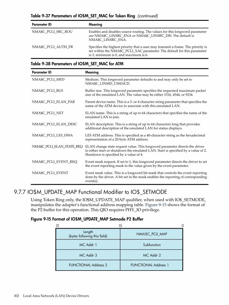
Table 9-37 Parameters of IO$M_SET_MAC for Token Ring (continued)
MeaningParameter ID
Enables and disables source routing. The values for this longword parameterare NMA$C_LINSRC_ENA or NMA$C_LINSRC_DIS. The default isNMA$C_LINSRC_ENA.
NMA$C_PCLI_SRC_ROU
Specifies the highest priority that a user may transmit a frame. The priority isset within the NMA$C_PCLI_XAC parameter. The default for this parameteris 3, minimum is 0, and maximum is 6.
NMA$C_PCLI_AUTH_PR
Table 9-38 Parameters of IO$M_SET_MAC for ATM
MeaningParameter ID
Medium. This longword parameter defaults to and may only be set toNMA$C_LINMD_CSMACD.
NMA$C_PCLI_MED
Buffer size. This longword parameter specifies the requested maximum packetsize of the emulated LAN. The value may be either 1516, 4544, or 9234.
NMA$C_PCLI_BUS
Parent device name. This is a 3- or 4-character string parameter that specifies thename of the ATM device to associate with this emulated LAN.
NMA$C_PCLI_ELAN_PAR
ELAN name. This is a string of up to 64 characters that specifies the name of theemulated LAN to join.
NMA$C_PCLI_NET
ELAN description. This is a string of up to 64 characters long that providesadditional description of the emulated LAN for status displays.
NMA$C_PCLI_ELAN_DESC
LES ATM address. This is specified as a 40-character string as the hexadecimalrepresentation of a 20-byte ATM address.
NMA$C_PCLI_LES_HWA
ELAN change state request value. This longword parameter directs the driverto either start or shutdown the emulated LAN. Start is specified by a value of 2.Shutdown is specified by a value of 4.
NMA$C_PCLI_ELAN_STATE_REQ
Event mask request. If set to 1, this longword parameter directs the driver to setthe event reporting mask to the value given by the event parameter.
NMA$C_PCLI_EVENT_REQ
Event mask value. This is a longword bit mask that controls the event reportingdone by the driver. A bit set in the mask enables the reporting of correspondingevent(s).
NMA$C_PCLI_EVENT
9.7.7 IO$M_UPDATE_MAP Functional Modifier to IO$_SETMODEUsing Token Ring only, the IO$M_UPDATE_MAP qualifier, when used with IO$_SETMODE,manipulates the adapter's functional address mapping table. Figure 9-15 shows the format ofthe P2 buffer for this operation. This QIO requires PHY_IO privilege.
Figure 9-15 Format of IO$M_UPDATE_MAP Setmode P2 Buffer
Length(bytes following this field)
MC Addr 1 Subfunction
MC Addr 3 MC Addr 2
FUNCTIONAL Address 2 FUNCTIONAL Address 1
NMA$C_PCLI_MAP
31 15 0
302 Local Area Network (LAN) Device Drivers

The subfunction is one of the following:• NMA$C_MAP_CHANGE — This function adds or changes a mapping in the functional
address table. If the specified multicast entry does not exist, an entry is created with thespecified functional address mask. If the specified multicast entry does exist, thecorresponding functional address mask is changed to the specified mask. All users whocurrently have the multicast enabled when the functional mask is changed will automaticallyupdate the functional address table as part of this operation.Possible errors returned include the following:— SS$_DEVICEFULL — This error indicates that there is insufficient space in the mapping
table to complete the request. The multicast to functional address mapping table has200 entries.
• NMA$C_MAP_DELETE — This function deletes the specified MC address in the table. Forthis function, the functional address mask is not required to pass the P2 buffer. If thefunctional address mask is passed, its contents are ignored.Possible errors returned include the following:— SS$_BADPARAM — This error indicates that the specified multicast address cannot be
found in the table.
The following example maps multicast address AB-01-01-01-02-03 to the functional address03-00-00-01-00-00 for device ICA0:.LANCP>SET DEVICE/MAP= -_LANCP>(MULTICAST=AB-01-01-01-02-03, -_LANCP>FUNCTIONAL=00-01-00-00) ICA0:
The following example deletes the mapping of the multicast address of AB-01-01-01-02-03 forthe device ICA0:.LANCP>SET DEVICE/NOMAP=(MULTICAST=AB-01-01-01-02-03) ICA0:
9.7.8 IO$M_ROUTE Functional Modifier to IO$_SETMODEFor Token Ring only, the IO$M_ROUTE qualifier, when used with IO$_SETMODE, manipulatesthe source routing cache table. This command is successful only when source routing is enabled.Source routing is enabled with the set mac qualified set mode QIO. Figure 9-16 shows the formatof the P2 buffer. This QIO requires the PHY_IO privilege.
Figure 9-16 Format of the IO$M_ROUTE P2 Buffer31 15 0
Length(bytes following this field)
MC Addr 1 Subfunction
MC Addr 3 MC Addr 2
Routing Information String030 bytes.
RI_Size
NMA$C_PCLI_MAP
The subfunction is one of the following:• NMA$C_SR_ADD — This function adds or changes a source routing cache entry. It enters
the LAN address into the table with the enclosed routing information. The routing
9.7 LAN Function Codes 303
information string format is documented in “Token Ring Frames ” (page 262) . If RI_size ispassed as 0, the entry is created (or modified) to be in the EXPLORING state (this is usefulfor users who are doing their own source routing). If the RC 'Lth' field is 0, the LAN addressis entered in the table as being in the local state.Possible errors returned include:— SS$_INSFMEM — The source routing cache is full.— SS$_BADPARAM — An invalid RI string was passed or invalid sizes were passed.— SS$_IVMODE — Source routing is not enabled.
• NMA$C_SR_DELETE — This function deletes a source routing cache entry. The RI_sizeand the routing information string are not required for this QIO. If one or both of the fieldsare passed for this operation, they are ignored. The result of this command is to put theentry into the deleted state. When the entry goes into the deleted state, it is deleted within10 minutes.Possible errors returned include the following:— SS$_BADPARAM — The requested entry could not be found.
9.7.9 Sense Mode and Sense CharacteristicsThe sense mode function returns the port attributes in the specified buffer. These attributesinclude the device characteristics described in “LAN Device Information” (page 283) and, withthe exceptions noted below, the attributes listed in Table 9-33.The following combinations of function code and modifier are provided:• IO$_SENSEMODE!IO$M_CTRL—Read characteristics• IO$_SENSECHAR!IO$M_CTRL—Read characteristics• IO$_SENSEMODE!IO$M_SENSE_MAC—Medium specific characteristics• IO$_SENSEMODE!IO$M_SHOW_MAP—Returns current functional address to multicast
address mapping (Token Ring only)• IO$_SENSEMODE!IO$M_SHOW_ROUTE—Returns current source routing cache table
(Token Ring only)These functions take the following device- or function-dependent arguments:• P1—The address of a two-longword buffer where the device characteristics are stored.
(Figure 9-17 shows the format for, and “LAN Device Information” (page 283) describes thecontents of, the P1 buffer.) The P1 argument is optional.
• P2—The address of a quadword descriptor where the attributes buffer is stored. The firstlongword of the descriptor is the buffer length; the second longword is the address of thebuffer. The P2 argument is optional.The P2 buffer is not read by the LAN driver. The driver stores the port's attributes in thebuffer, which contains multiple entries. The format of each entry depends on whether alongword or a counted string is returned, as shown in Figure 9-18. Each parameter IDcontains a string indicator bit (bit 12) that describes whether the data item is a string or alongword.
Except for the following differences, P2 returns the same attributes as those listed in Table 9-31:• All parameters that are valid for the enabled packet format are returned (see Table 9-32).• The sense-mode P2 buffer does not return the modifier word for the NMA$C_PCLI_PHA,
NMA$C_PCLI_MCA, and NMA$C_PCLI_DES parameter IDs.
304 Local Area Network (LAN) Device Drivers

• The NMA$C_PCLI_DES parameter is only returned on Ethernet ports whose access modeis set to “shared with destination.”
• In addition to the parameter IDs listed in Table 9-31, the sense-mode P2 buffer contains thefollowing parameter IDs:2
MeaningParameter ID
List of the currently enabled functional addresses (Token Ring only). Each 32-bitentry corresponds respectively with the items returned under NMA$C_PCLI_MCA.
NMA$C_PCLI_FCA
Hardware address. Describes the value for the hardware address. The hardwareaddress is the default physical address when no physical address has been specifiedand there are no active users on the controller. NMA$C_PCLI_HWA is returnedin the same format as NMA$C_PCLI_PHA.
NMA$C_PCLI_HWA
Maximum packet length. NMA$C_PCLI_MBS is a longword, read-only parameter.The value returned reflects the largest data packet that the application can receivefor its packet format and type of LAN, measured in bytes. The values for Ethernet,FDDI, and Token Ring are:
NMA$C_PCLI_MBS
Token RingFDDIEthernetPacket Format
441844701500Ethernet format without padding
441644681498Ethernet format with padding
442344751497802 format with 1-byte CTL field
441844701492802E format
The values for LAN emulation over ATM are:
923445441516ATM ELAN size:Packet Format
921845281500Ethernet format without padding
921645261498Ethernet format with padding
921545251497802 format with 1-byte CTL field
921045201492802E format
Figure 9-17 Sense Mode P1 Characteristics Buffer
Maximum Message Size Type
Not Used Not UsedError Summary Status
Class
31 1516 78 02324
It is suggested that a size of 250 bytes be used for the P2 buffer. This allows space for additionalparameters that may be returned in future releases of OpenVMS.All attributes that fit into the buffer specified by P2 are returned; however, if all the attributescannot be stored in the buffer, the I/O status block returns the status SS$_BUFFEROVF. Thesecond word of the I/O status block contains the number of bytes used in the P2 buffer (see “I/OStatus Block” (page 310)).
2. Alpha specific.
9.7 LAN Function Codes 305

Figure 9-18 Sense Mode Attribute Buffer
0 0 Parameter ID
Longword Parameter:
Longword of
Value
15 1314 12 11 0
*
* Not Used
0 1 Parameter ID
String
String Parameter:
Word of String Count
15 1314 12 11 0
*
* Not Used
9.7.10 IO$M_SENSE_MAC Functional Modifier to IO$_SENSEMODEThe IO$M_SENSE_MAC qualifier, when used with IO$_SENSEMODE, returns the parametersspecified in “IO$M_SET_MAC Functional Modifier to IO$M_SETMODE” (page 300). In additionto the set mac parameters, Table 9-39 shows the returns of the following parameters:
Table 9-39 Parameters of IO$M_SENSE_MAC
MeaningParameter ID
The negotiated value of the token rotation timer (ANSI MAC parameter T_neg)(FDDI only).
NMA$C_PCLI_T_NEG
The duplicate address test flag (FDDI only). If set, this indicates that there isanother station on the ring with the same hardware LAN address.
NMA$C_PCLI_DAT
Upstream neighbor's address (FDDI and Token Ring). This is a string parameterspecifying the 6-byte LAN address of the upstream neighbor. Not all devicesmay support this feature.
NMA$C_PCLI_UNA
The old (previous) upstream neighbor address (FDDI only). Neighbor addresseschange as nodes insert and deinsert into the ring.
NMA$C_PCLI_OLD_UNA
The upstream neighbor's duplicate address test flag (FDDI only).NMA$C_PCLI_UN_DAT
The downstream neighbor's LAN address (FDDI only).NMA$C_PCLI_DNA
The old (previous) downstream neighbor's LAN address (FDDI only).NMA$C_PCLI_OLD_DNA
The current ring purger state (FDDI only). This longword parameter is one ofthe following values:• 0 — Off• 1 — Candidate• 2 — Non-purger• 3 — Purger
NMA$C_PCLI_RPS
306 Local Area Network (LAN) Device Drivers

Table 9-39 Parameters of IO$M_SENSE_MAC (continued)
MeaningParameter ID
The latest ring error reason (FDDI only). This longword parameter is one of thefollowing values:• 0 — No Error• 5 — Ring Init initiated• 6 — Ring Init received• 7 — Ring beaconing initiated• 8 — Duplicate address detected• 9 — Duplicate token detected• 10 — Ring purger error• 11 — FCI strip error• 12 — Ring op oscillation• 14 — PC trace initiated• 15 — PC trace received
NMA$C_PCLI_RER
Neighbor's PHY type (FDDI only). This longword parameter is one of thefollowing values:• 0 — A• 1 — B• 2 — S• 3 — M• 4 — Unknown
NMA$C_PCLI_NBR_PHY
Ring reject reason (FDDI only). This longword parameter is one of the followingvalues:• 0 — None• 1 — Local LCT• 2 — Remote LCT• 3 — LCT both sides• 4 — LEM reject• 5 — Topology error• 6 — Noise reject• 7 — Remote reject• 8 — Trace in progress• 9 — Trace received-disabled• 10 — Standby• 11 — LCT protocol error
NMA$C_PCLI_RJR
Link error estimate (FDDI only). The longword value is a negative exponent of10 representing the Link error rate. For example, the value of X represents theerror rate of 10^X.
NMA$C_PCLI_LEE
The longword value contains the ring number that the controller is running on(Token Ring only). It is only valid for a controller that is started, and also onlyvalid for rings that have a ring parameter server that is configured for providingthis information.
NMA$C_PCLI_RNG_NUM
9.7 LAN Function Codes 307

9.7.11 IO$M_SHOW_MAP Functional Modifier to IO$_SENSEMODEFor Token Ring only, the IO$M_SHOW_MAP qualifier, when used with IO$_SENSEMODE,returns the current setting of the mapping table. The P2 buffer is filled with the current multicastto functional address mapping information. The entries are 16 bytes long and are in the formatshown in Figure 9-19. This QIO requires PHY_IO privilege.
Figure 9-19 Format of IO$M_SHOW_MAP P2 Buffer31 15 0
Multicast 2
Reserved
Reserved Reserved
Multicast 3
Functional Address Mark
Multicast 1
The multicast address and functional address mask are returned in canonical format (that is, notbit-reversed). The following errors may occur:• SS$_BUFFEROVF — The passed buffer is not large enough to hold all the data required for
the operation.• SS$_BADPARAM — Not able to get read access to buffer or zero length buffer passed.
9.7.12 IO$M_SHOW_ROUTE Functional Modifier to IO$_SENSEMODEFor Token Ring only, the IO$M_SHOW_ROUTE qualifier, when used with IO$_SENSEMODE,returns the current value of the source routing cache table. Each entry is 64 bytes long. Figure 9-20shows the format of the returned P2 buffer.
308 Local Area Network (LAN) Device Drivers

Figure 9-20 Format of IO$M_SHOW_ROUTE P2 Buffer31 15 0
LAN Addr 2 LAN Addr 1
LAN Addr 3Reserved
Segment Descriptor
Segment Descriptor Segment Descriptor
Segment Descriptor Segment Descriptor
Segment Descriptor Segment Descriptor
Segment Descriptor Segment Descriptor
Segment Descriptor Segment Descriptor
Segment Descriptor Segment Descriptor
Routing Control Field
State of Entry
Last Transmit Timer
Last Receive Timer
Stale Timer
Discovery Timer
Routing Information String Size
Table 9-40 shows possible states of the entry.
Table 9-40 State of the Entry
DescriptionNameValue
Address is reachable on the attached ring.LOCAL0
Entry is stale (inactive).STALE1
Route to the address is unknown.UNKNOWN2
Entry is marked for deletion.DELETED3
Route is known and the route is stored in the routing information string.KNOWN4
Route to the address is currently being explored.EXPLORING5
The LAN address is returned in canonical format (that is, not bit-reversed). The timers arerecorded as seconds before expiration. The transmit and receive timers are initialized from theNMA$C_PCLI_A_TIM parameter, the discovery timer is initialized from the
9.7 LAN Function Codes 309
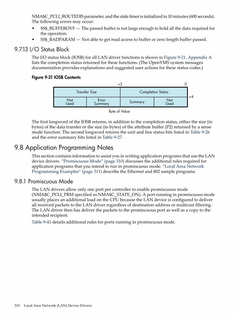
NMA$C_PCLI_ROUTEDIS parameter, and the stale timer is initialized to 10 minutes (600 seconds).The following errors may occur:• SS$_BUFFEROVF — The passed buffer is not large enough to hold all the data required for
the operation.• SS$_BADPARAM — Not able to get read access to buffer or zero length buffer passed.
9.7.13 I/O Status BlockThe I/O status block (IOSB) for all LAN driver functions is shown in Figure 9-21. Appendix Alists the completion status returned for these functions. (The OpenVMS system messagesdocumentation provides explanations and suggested user actions for these status codes.)
Figure 9-21 IOSB Contents
Transfer Size
NotUsed SummaryError
SummaryNotUsed
Completion Status
+2
+4
Byte of Value
0
The first longword of the IOSB returns, in addition to the completion status, either the size (inbytes) of the data transfer or the size (in bytes) of the attribute buffer (P2) returned by a sensemode function. The second longword returns the unit and line status bits listed in Table 9-26and the error summary bits listed in Table 9-27.
9.8 Application Programming NotesThis section contains information to assist you in writing application programs that use the LANdevice drivers. “Promiscuous Mode” (page 310) discusses the additional rules required forapplication programs that you intend to run in promiscuous mode. “Local Area NetworkProgramming Examples” (page 311) describe the Ethernet and 802 sample programs.
9.8.1 Promiscuous ModeThe LAN drivers allow only one port per controller to enable promiscuous mode(NMA$C_PCLI_PRM specified as NMA$C_STATE_ON). A port running in promiscuous modeusually places an additional load on the CPU because the LAN device is configured to deliverall received packets to the LAN driver regardless of destination address or multicast filtering.The LAN driver then has deliver the packets to the promiscuous port as well as a copy to theintended recipient.Table 9-41 details additional rules for ports running in promiscuous mode.
310 Local Area Network (LAN) Device Drivers

Table 9-41 Rules for Promiscuous Mode Operation
RuleI/O Function
It is not necessary to specify a unique identifier (a protocol type, SAP, or protocol identifierparameter ID) in the P2 buffer.The port cannot be running in shared mode.
IO$_SETMODEIO$_SETCHAR
The user can only transmit packets in the packet format previously specified with a setmode QIO when the user was started. The unique identifier for the packet format mustbe included in the P5 buffer following the destination address (see “Write” (page 287) ).
IO$_WRITE
The LAN driver completes the promiscuous user's read requests with Ethernet, 802, and802 extended packets. Because any packet format can be used to complete a read request,the P5 parameter (if specified) must be at least 20 bytes in length (21 bytes for FDDI withRFC turned on).All Ethernet format packets are processed as if they have no size field specified after theprotocol type. Therefore, Ethernet packets are always returned with 46 to 1500 bytes ofdata. If the Ethernet packet contains a size field, it is returned as part of the user data inthe first word of the P1 buffer.The promiscuous user should use the information returned in the P5 buffer to determinethe packet format. If the application program first filled the P5 buffer with zeros, theprogram can determine the format of the packet received by scanning the P5 buffer afterthe read request is completed.
IO$_READ
9.8.2 Local Area Network Programming ExamplesThe MACRO program LANETH.MAR (Example 9-2 shows the typical use of QIO functions indriver operations such as establishing the protocol type, starting the port, and transmitting andreceiving data. The program sends a LOOPBACK packet and waits for the packet to be returned.The HP C program LAN802E.C (Example 9-3 ) shows how to initialize an 802E port and how tosend and receive packets on that port. This program sends a LOOPBACK packet and waits forthe packet to be returned.
9.8 Application Programming Notes 311

Example 9-2 LANETH.MAR Local Area Network Programming Example
.TITLE LAN SAMPLE TEST PROGRAM .IDENT /X03/ .PSECT RWDATA,WRT,NOEXE,PAGE
; This LAN test program sends a MOP loopback message to the Loopback Assistant; Multicast address and waits for a response. The program uses the LAN device; EWA0. To use a different device, change the device name in the program or; define the desired lan device as EWA0.; * To build on VAX, Alpha, I64:; $ MACRO/OBJECT=LANETH/LIST=LANETH SYS$LIBRARY:ARCH_DEFS.MAR+SYS$DISK:[]LANETH; $ LINK LANETH;; To run:; $ RUN LANETH
.LIBRARY "SYS$LIBRARY:LIB.MLB"
$IODEF ; Define I/O functions and modifiers $NMADEF ; Define Network Management parameters
; Setmode parameter buffer and descriptor. Since the loopback protocol does; not include a length word following the protocol type, we have to explicitly; turn off padding since the default is on.
SETPARM: .WORD NMA$C_PCLIFMT ; Packet format .LONG NMA$C_LIFM_ETH ; Ethernet .WORD NMA$C_PCLI_PTY ; Protocol type .LONG ^X0090 ; Loopback .WORD NMA$C_PCLI_PAD ; Padding .LONG NMA$C_STATE_OFF ; Off SETPARMLEN = .-SETPARM
SETPARMDSC: .LONG SETPARMLEN .ADDRESS SETPARM
; Sensemode parameter buffer and descriptor. This is used to get our physical; address to put into the loopback message.
SENSEBUF: .BLKB 512SENSELEN=.-SENSEBUF
SENSEDSC: .LONG SENSELEN .ADDRESS SENSEBUF
; P2 transmit data buffer.
XMTBUF: .WORD 00 ; Skip count .WORD 02 ; Forward request FORW: .BLKB 6 ; Forward address .WORD 01 ; Reply request .WORD 00XMTBUFLEN = .-XMTBUF ; Size of transmit buffer
; P5 transmit destination address, the Loopback Assistant Multicast Address.
XMTP5: .BYTE ^XCF,0,0,0,0,0
; P2 receive data buffer.
RCVBUF: .BLKB 512RCVBUFLEN = .-RCVBUF ; Size of receive buffer
; P5 receive header buffer.
RCVP5:
312 Local Area Network (LAN) Device Drivers

RCVDA: .BLKB 6RCVSA: .BLKB 6RCVPTY: .BLKB 2
; Messages used to display status of this program.
GMSG: .ASCID "Successful test"LMSG: .ASCID "No response"EMSG: .ASCID "Error occurred while running test"DMSG: .ASCID "LAN device not found"
; Miscellaneous data.
IOSB: .BLKQ 1 ; I/O status block DEVCHAN:.BLKL 1 ; Returned port number LANDSC: .ASCID 'EWA0' ; Device to use for test
;*************************************************************************;; Start of code;;*************************************************************************
.PSECT CODE,EXE,NOWRT,PAGE .ENTRY START,^M<>
; Assign a port to the LAN device.
$ASSIGN_S DEVNAM=LANDSC,CHAN=DEVCHAN BLBS R0,10$ ; Branch if succeeded MOVAL DMSG,R9 ; Get address of error message BRW EXIT ; Print message and exit
; Set up the port's characteristics.
10$: MOVAL EMSG,R9 ; Assume error message address $QIOW_S FUNC=#<IO$_SETMODE!IO$M_CTRL!IO$M_STARTUP>,- CHAN=DEVCHAN,IOSB=IOSB,- P2=#SETPARMDSC BLBC R0,20$ ; Branch if failed MOVZWL IOSB,R0 ; Get status from IOSB BLBS R0,30$ ; Branch if succeeded 20$: BRW EXIT ; Print message and exit
; Issue the SENSEMODE QIO to get our physical address for the loopback; message.
30$: $QIOW_S FUNC=#<IO$_SENSEMODE!IO$M_CTRL>,- CHAN=DEVCHAN,IOSB=IOSB,- P2=#SENSEDSC BLBC R0,20$ ; Branch if failed MOVZWL IOSB,R0 ; Get status from IOSB BLBC R0,20$ ; Branch if failed
; Locate the PHA parameter in the SENSEMODE buffer and copy it into the; LOOPBACK transmit message. The PHA parameter is a string parameter.
MOVAB SENSEBUF,R0 ; Start at beginning of buffer 40$: BBS #^XC,(R0),50$ ; Branch if a string parameter ADDL #6,R0 ; Skip over longword parameter BRB 40$ ; Check next parameter 50$: BICW3 #^XF000,(R0)+,R1 ; Get type field less flag bits CMPW R1,#NMA$C_PCLI_PHA ; Is this the PHA parameter? BEQL 60$ ; Branch if so ADDW (R0)+,R0 ; Skip over string parameter BRW 40$ ; Check next parameter .IF NOT_DEFINED VAX .DISABLE FLAGGING.ENDC60$: MOVL 2(R0),FORW ; Copy our address to the loopback MOVW 6(R0),FORW+4 ; packet we are about to transmit .IF NOT_DEFINED VAX
9.8 Application Programming Notes 313
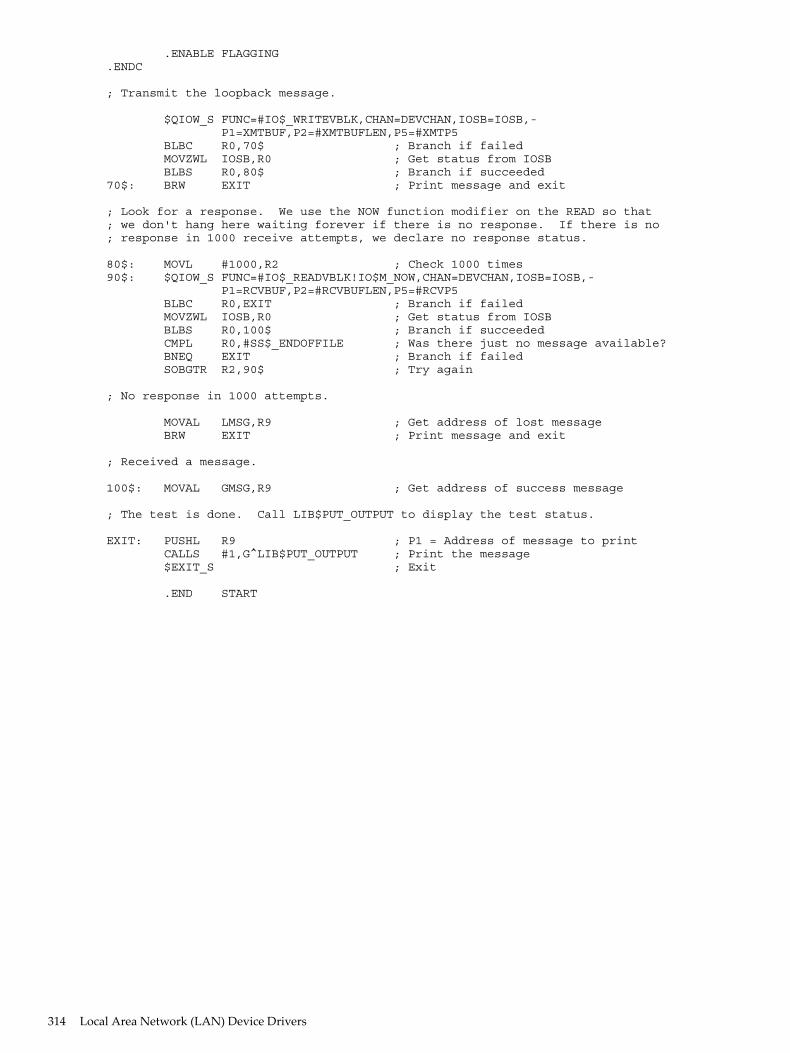
.ENABLE FLAGGING.ENDC
; Transmit the loopback message.
$QIOW_S FUNC=#IO$_WRITEVBLK,CHAN=DEVCHAN,IOSB=IOSB,- P1=XMTBUF,P2=#XMTBUFLEN,P5=#XMTP5 BLBC R0,70$ ; Branch if failed MOVZWL IOSB,R0 ; Get status from IOSB BLBS R0,80$ ; Branch if succeeded 70$: BRW EXIT ; Print message and exit
; Look for a response. We use the NOW function modifier on the READ so that; we don't hang here waiting forever if there is no response. If there is no; response in 1000 receive attempts, we declare no response status.
80$: MOVL #1000,R2 ; Check 1000 times90$: $QIOW_S FUNC=#IO$_READVBLK!IO$M_NOW,CHAN=DEVCHAN,IOSB=IOSB,- P1=RCVBUF,P2=#RCVBUFLEN,P5=#RCVP5 BLBC R0,EXIT ; Branch if failed MOVZWL IOSB,R0 ; Get status from IOSB BLBS R0,100$ ; Branch if succeeded CMPL R0,#SS$_ENDOFFILE ; Was there just no message available? BNEQ EXIT ; Branch if failed SOBGTR R2,90$ ; Try again
; No response in 1000 attempts.
MOVAL LMSG,R9 ; Get address of lost message BRW EXIT ; Print message and exit
; Received a message.
100$: MOVAL GMSG,R9 ; Get address of success message
; The test is done. Call LIB$PUT_OUTPUT to display the test status.
EXIT: PUSHL R9 ; P1 = Address of message to print CALLS #1,G^LIB$PUT_OUTPUT ; Print the message $EXIT_S ; Exit
.END START
314 Local Area Network (LAN) Device Drivers

Example 9-3 LAN802.C Local Area Network Programming Example
/************************************************************* * LAN Sample Test Program * * This LAN test program sends a MOP loopback message to the Loopback Assistant * Multicast address and waits for a response. The program uses the LAN device * EWA0. To use a different device, change the device name in the program or * define the desired lan device as EWA0. * * To build on VAX: * $ CC LAN802E * $ LINK LAN802E,SYS$INPUT:/OPT * SYS$SHARE:VAXCRTL.EXE/SHARE * * Note: NMADEF.H must be supplied containing definitions for: * * #define NMA$C_PCLIFMT 2770 * #define NMA$C_PCLI_PID 2774 * #define NMA$C_PCLI_PHA 2820 * #define NMA$C_LIFM_802E 0 * * To build on Alpha, I64: * $ CC LAN802E+SYS$LIBRARY:SYS$LIB_C.TLB/LIB * $ LINK LAN802E * * To run: * $ RUN LAN802E *************************************************************/
#include <ctype> /* Character type classification macros/routines */#include <descrip> /* For VMS descriptor manipulation */#include <iodef> /* I/O function code definitions */#include "nmadef.h" /* LAN parameter definitions */#include <ssdef> /* System service return status code definitions */#include <starlet> /* System library routine prototypes */#include <stdio> /* ANSI C Standard Input/Output */#include <stdlib> /* General utilities */#include <string> /* String handling */#include <stsdef> /* VMS status code definitions */
#define $SUCCESS(status) (((status) & STS$M_SUCCESS) == SS$_NORMAL)#define $FAIL(status) (((status) & STS$M_SUCCESS) != SS$_NORMAL)
#pragma nomember_alignment
struct parm_802e{ short pcli_fmt; /* Format - 802E */ int fmt_value; short pcli_pid; /* Protocol ID - 08-00-2B-90-00 */ short pid_length; char pid_value[5];} setparm_802e = {NMA$C_PCLIFMT, NMA$C_LIFM_802E, NMA$C_PCLI_PID, 5, 8,0,0x2B,0x90,0};
struct setparmdsc{ int parm_len; void *parm_buffer;};
struct setparmdsc setparmdsc_loop = { sizeof(setparm_802e),&setparm_802e};
struct p5_param /* P5 Receive header buffer */{ unsigned char da[6]; unsigned char sa[6]; char misc[20];};
struct iosb /* IOSB structure */{ short w_err; /* Completion status */ short w_xfer_size; /* Transfer size */ short w_addl; /* Additional status */ short w_misc; /* Miscellaneous */};
struct ascid /* Device descriptor for assign */{ short w_len; short w_info; char *a_string;} devdsc = {4,0,"EWA0"};
struct iosb qio_iosb; /* IOSB structure */struct p5_param rcv_param; /* Receive header structure */struct p5_param xmt_param = { /* Transmit header structure */ 0xCF,0,0,0,0,0};char rcv_buffer[512]; /* Receive buffer */
9.8 Application Programming Notes 315

char xmt_buffer[20] = { /* Transmit buffer */ 0,0, /* Skip count */ 2,0, /* Forward request */ 0,0,0,0,0,0, /* Forward address */ 1,0, /* Reply request */ 0,0};
char sense_buffer[512]; /* Sensemode buffer */
struct setparmdsc sensedsc_loop = {sizeof(sense_buffer),sense_buffer};
/* * MAIN */
main(int argc, char *argv[]){ int i, j; /* Scratch */ int chan; /* Channel assigned */ int status; /* Return status */
/* * Start a channel. */
status = sys$assign(&devdsc,&chan,0,0); if ($FAIL(status)) exit(status); status = sys$qiow(0,chan,IO$_SETMODE|IO$M_CTRL|IO$M_STARTUP,&qio_iosb,0,0,0,&setparmdsc_loop,0,0,0,0); if ($SUCCESS(status)) status = qio_iosb.w_err; if ($FAIL(status)) { printf("IOSB addl status = %04X %04X\n",qio_iosb.w_addl,qio_iosb.w_misc); exit(status); }
/* * Issue the SENSEMODE QIO to get our physical address for the loopback message. */
status = sys$qiow(0,chan,IO$_SENSEMODE|IO$M_CTRL,&qio_iosb,0,0,0,&sensedsc_loop,0,0,0,0); if ($SUCCESS(status)) status = qio_iosb.w_err; if ($FAIL(status)) { printf("IOSB addl status = %04X %04X\n",qio_iosb.w_addl,qio_iosb.w_misc); exit(status); }
/* * Locate the PHA parameter in the SENSEMODE buffer and copy it into the * LOOPBACK transmit message. The PHA parameter is a string parameter. */
j = 0; while (j < sizeof(sense_buffer)) { i = (sense_buffer[j] + (sense_buffer[j+1] << 8)); if (0x1000 & i) { if ((i & 0xFFF) == NMA$C_PCLI_PHA) { memcpy(&xmt_buffer[4],&sense_buffer[j+4],6); break; } j += (sense_buffer[j+2] + (sense_buffer[j+3] << 8)) + 4; } else j += 6; /* Skip over longword parameter */ }
/* * Transmit the loopback message. */
status = sys$qiow(0,chan,IO$_WRITEVBLK,&qio_iosb,0,0,&xmt_buffer[0], sizeof(xmt_buffer),0,0,&xmt_param,0); if ($SUCCESS(status)) status = qio_iosb.w_err; if ($FAIL(status)) { printf("IOSB addl status = %04X %04X (on transmit)\n", qio_iosb.w_addl,qio_iosb.w_misc); exit(status); }
/* * Look for a response. We use the NOW function modifier on the READ so that * we don't hang here waiting forever if there is no response. If there is no * response in 1000 receive attempts, we declare no response status. */
for (i=0;i<1000;i++) { status = sys$qio(0,chan,IO$_READVBLK|IO$M_NOW,&qio_iosb,0,0,&rcv_buffer[0], sizeof(rcv_buffer),0,0,rcv_param,0); if ($SUCCESS(status)) status = qio_iosb.w_err; if ($SUCCESS(status)) break; } if ($SUCCESS(status)) printf("Successful test\n"); else printf("No response\n");}
316 Local Area Network (LAN) Device Drivers

10 Optional Features for Improving I/O PerformanceTwo features of OpenVMS Alpha and Integrity servers provide dramatically improved I/Operformance: Fast I/O and Fast Path. These features are designed to promote OpenVMS as aleading platform for database systems. Performance improvement results from reducing theCPU cost per I/O request and improving symmetric multiprocessing (SMP) scaling of I/Ooperations. The CPU cost per I/O is reduced by optimizing code for high-volume I/O and byusing better SMP CPU memory cache. SMP scaling of I/O is increased by reducing the numberof spinlocks taken per I/O and by substituting finer-granularity spinlocks for global spinlocks.The improvements follow a natural division that already exists between the device-independentand device-dependent layers in the OpenVMS I/O subsystem. The device-independent overheadis addressed by Fast I/O, which is a set of lean system services that can substitute for certain$QIO operations. Using these services requires some coding changes in existing applications,but the changes are usually modest and well contained. The device-dependent overhead isaddressed by Fast Path, which is an optional performance feature that creates a “fast path” tothe device. It requires no application changes.Fast I/O and Fast Path can be used independently; however, together they can provide a 45percent reduction in CPU cost per I/O on uniprocessor systems and a 52 percent reduction onmultiprocessor systems.
10.1 Fast I/OFast I/O is a set of three system services that were developed as a $QIO alternative built for speed.These services are not a $QIO replacement; $QIO is unchanged, and $QIO interoperation withthese services is fully supported. Rather, the services substitute for a subset of $QIO operations,namely, only the high-volume read/write I/O requests.The Fast I/O services support 64-bit addresses for data transfers to and from disk and tape devices.While Fast I/O services are available on OpenVMS VAX, the performance advantage appliesonly to OpenVMS Alpha and Integrity servers. OpenVMS VAX has a run-time library (RTL)compatibility package that translates the Fast I/O service requests to $QIO system service requests,so one set of source code can be used on VAX, Alpha, and Integrity server systems.
10.1.1 Fast I/O BenefitsThe performance benefits of Fast I/O result from streamlining high-volume I/O requests. TheFast I/O system service interfaces are optimized to avoid the overhead of general-purpose services.For example, I/O request packets (IRPs) are now permanently allocated and used repeatedly forI/O rather than allocated and deallocated anew for each I/O.The greatest benefits stem from having user data buffers and user I/O status structurespermanently locked down and mapped using system space. This allows Fast I/O to do thefollowing:• For direct I/O, avoid per-I/O buffer lockdown or unlocking.• For buffered I/O, avoid allocation and deallocation of a separate system buffer, because the
user buffer is always addressable.• Complete Fast I/O operations at IPL 8, thereby avoiding the interrupt chaining usually
required by the more general-purpose $QIO system service. For each I/O, this eliminatesthe IPL 4 IOPOST interrupt and a kernel AST.
In total, Fast I/O services eliminate four spinlock acquisitions per I/O (two for the MMG spinlockand two for the SCHED spinlock). The reduction in CPU cost per I/O is 20 percent for uniprocessorsystems and 10 percent for multiprocessor systems.
10.1 Fast I/O 317
10.1.2 Using Buffer ObjectsThe lockdown of user-process data structures is accomplished by buffer objects. A “buffer object”is process memory whose physical pages have been locked in memory and double-mapped intosystem space. After creating a buffer object, the process remains fully pageable and swappableand the process retains normal virtual memory access to its pages in the buffer object.If the buffer object contains process data structures to be passed to an OpenVMS system service,the OpenVMS system can use the buffer object to avoid any probing, lockdown, and unlockingoverhead associated with these process data structures. Additionally, double-mapping intosystem space allows the OpenVMS system direct access to the process memory from systemcontext.To date, only the $QIO system service and the Fast I/O services have been changed to acceptbuffer objects. For example, a buffer object allows a programmer to eliminate I/O memorymanagement overhead. On each I/O, each page of a user data buffer is probed and then lockeddown on I/O initiation and unlocked on I/O completion. Instead of incurring this overhead foreach I/O, it can be done once at buffer object creation time. Subsequent I/O operations involvingthe buffer object can completely avoid this memory management overhead.Two system services can be used to create and delete buffer objects, respectively, and can becalled from any access mode. To create a buffer object, the $CREATE_BUFOBJ system service iscalled. This service expects as inputs an existing process memory range and returns a bufferhandle for the buffer object. The buffer handle is an opaque identifier used to identify the bufferobject on future I/O requests. The $DELETE_BUFOBJ system service is used to delete the bufferobject and accepts as input the buffer handle. Although image rundown deletes all existing bufferobjects, it is good form for the application to clean up properly.A 64-bit equivalent version of the $CREATE_BUFOBJ system service ($CREATE_BUFOBJ_64)can be used to create buffer objects from the new 64-bit P2 or S2 regions. The $DELETE_BUFOBJsystem service can be used to delete 32-bit or 64-bit buffer objects.Buffer objects require system management. Because buffer objects tie up physical memory,extensive use of buffer objects requires system management planning. All the bytes of memoryin the buffer object are deducted from a systemwide system parameter called MAXBOBMEM(maximum buffer object memory). System managers must set this parameter correctly for theapplication loads that run on their systems.The MAXBOBMEM parameter defaults to 100 Alpha pages, but for applications with large bufferpools it will likely be set much larger. To prevent user-mode code from tying up excessive physicalmemory, user-mode callers of $CREATE_BUFOBJ must have a new system identifier,VMS$BUFFER_OBJECT_USER, assigned. This new identifier is automatically created in anOpenVMS Version 7.0 upgrade if the file SYS$SYSTEM:RIGHTSLIST.DAT is present. The systemmanager can assign this identifier with the DCL command SET ACL command to a protectedsubsystem or application that creates buffer objects from user mode. It may also be appropriateto grant the identifier to a particular user with the Authorize utility commandGRANT/IDENTIFIER (for example, to a programmer who is working on a development system).There is currently a restriction on the type of process memory that can be used for buffer objects.Global section memory cannot be made into a buffer object.
10.1.3 Differences Between Fast I/O Services and $QIOThe precise definition of high-volume I/O operations optimized by Fast I/O services is important.I/O that does not comply with this definition either is not possible with the Fast I/O services oris not optimized. The characteristics of the high-volume I/O optimized by Fast I/O services canbe seen by contrasting the operation of Fast I/O system services to the $QIO system service asfollows:• The $QIO system service I/O status block (IOSB) is replaced by an I/O status area (IOSA)
that is larger and quadword aligned. The transfer byte count returned in IOSA is 64 bits,
318 Optional Features for Improving I/O Performance

and the field is aligned on a quadword boundary. Unlike the IOSB, which is optional, theIOSA is required.
• User data buffers must be aligned to a 512-byte boundary.• All user process structures passed to the Fast I/O system services must reside in buffer
objects. This includes the user data buffer and the IOSA.• Only transfers that are multiples of 512 bytes are supported.• Only the following function codes are supported: IO$_READVBLK, IO$_READLBLK,
IO$_WRITEVBLK, and IO$_WRITELBLK.• Only I/O to disk and tape devices is optimized for performance.• No event flags are used with Fast I/O services. If application code must use an event flag in
relation to a specific I/O, then the Event No Flag EFN (EFN$C_ENF) can be used. This eventflag is a no-overhead EFN that can be used in situations when an EFN is required by a systemservice interface but has no meaning to an application.For example, Fast I/O services do not use EFNs, so the application cannot specify a validEFN associated with the I/O to the $SYNCH system service with which to synchronize I/Ocompletion. To resolve this issue, the application can call the $SYNCH system service passingas arguments: EFN$C_ENF and the address of the appropriate IOSA. Specifying EFN$C_ENFsignifies to $SYNCH that no EFN is involved in the synchronization of the I/O. Once theIOSA has been written with a status and byte count, return from the $SYNCH call occurs.The IOSA is now the central point of synchronization for a given Fast I/O (and is the onlyway to determine whether the asynchronous I/O is complete).
• To minimize arguments passing overhead to these services, the $QIO parameters P3 throughP6 are replaced by a single argument that is passed directly by the Fast I/O system servicesto device drivers. For disk-like devices, this argument is the media address (VBN or LBN)of the transfer. For drivers with complex parameters, this argument is the address of adescriptor or of a buffer specific to the device and function.
• Segmented transfers are supported by Fast I/O but are not fully optimized. There are twomajor causes of segmented transfers. The first is disk fragmenting. While this can be an issue,it is assumed that sites seeking maximum performance have eliminated the overhead ofsegmenting I/O due to fragmentation.A second cause of segmenting is issuing an I/O that exceeds the port's maximum limit fora single transfer. Transfers beyond the port maximum limit are segmented into severalsmaller transfers. Some ports limit transfers to 64KB. If the application limits its transfers toless than 64KB, this type of segmentation should not be a concern.
10.1.4 Using Fast I/O ServicesThe three Fast I/O system services are:• $IO_SETUP—-Sets up an I/O• $IO_PERFORM[W]—-Performs an I/O request• $IO_CLEANUP—Cleans up an I/O request
10.1.4.1 Using FandlesA key concept behind the operation of the Fast I/O services is the file handle or fandle. A fandleis an opaque token that represents a “setup” I/O. A fandle is needed for each I/O outstandingfrom a process.All possible setup, probing, and validation of arguments is performed off the mainline code pathduring application startup with calls to the $IO_SETUP system service. The I/O function, theAST address, the buffer object for the data buffer, and the IOSA buffer object are specified oninput to $IO_SETUP service, and a fandle representing this setup is returned to the application.
10.1 Fast I/O 319

To perform an I/O, the $IO_PERFORM system service is called, specifying the fandle, the channel,the data buffer address, the IOSA address, the length of the transfer, and the media address(VBN or LBN) of the transfer.If the asynchronous version of this system service, $IO_PERFORM, is used to issue the I/O, thenthe application can wait for I/O completion using a $SYNCH specifying EFN$C_ENF and theappropriate IOSA. The synchronous form of the system service, $IO_PERFORMW, is used toissue an I/O and wait for it to complete. Optimum performance comes when the application usesAST completion; that is, the application does not issue an explicit wait for I/O completion.To clean up a fandle, the fandle can be passed to the $IO_CLEANUP system service.
10.1.4.2 Modifying Existing ApplicationsModifying an application to use the Fast I/O services requires a few source-code changes. Forexample:1. A programmer adds code to create buffer objects for the IOSAs and data buffers.2. The programmer changes the application to use the Fast I/O services. Not all $QIOs need
to be converted. Only high-volume read/write I/O requests should be changed.A simple example is a “database writer” program, which writes modified pages back to thedatabase. Suppose the writer can handle up to 16 simultaneous writes. At application startup,the programmer would add code to create 16 fandles by 16 $IO_SETUP system service calls.
3. In the main processing loop within the database writer program, the programmer replacesthe $QIO calls with $IO_PERFORM calls. Each $IO_PERFORM call uses one of the 16 availablefandles. While the I/O is in progress, the selected fandle is unavailable for use with otherI/O requests. The database writer is probably using AST completion and recycling fandle,data buffer, and IOSA once the completion AST arrives.If the database writer routine cannot return until all dirty buffers are written (that is, it mustwait for all I/O completions), then $IO_PERFORMW can be used. Alternatively$IO_PERFORM calls can be followed by $SYNCH system service calls passing theEFN$C_ENF argument to await I/O completions.The database writer runs faster and scale better because I/O requests now use less CPU time.
4. When the application exits, an $IO_CLEANUP system service call is done for each fandlereturned by a prior $IO_SETUP system service call. Then the buffer objects are deleted.Image rundown performs fandle and buffer object cleanup on behalf of the application, butit is good form for the application to clean up properly.
10.1.4.3 I/O Status Area (IOSA)The central point of synchronization for a given Fast I/O is its IOSA. The IOSA replaces the $QIOsystem service's IOSB argument. Larger than the IOSB argument, the byte count field in the IOSAis 64 bits and quadword aligned. Unlike the $QIO system service, Fast I/O services require thecaller to supply an IOSA and require the IOSA to be part of a buffer object.The IOSA context field can be used in place of the $QIO system service ASTPRM argument. The$QIO ASTPRM argument is typically used to pass a pointer back to the application on thecompletion AST to locate the user context needed for resuming a stalled user-thread; however,for the $IO_PERFORM system service, the ASTPRM on the completion AST is always the IOSA.Because there is no user-settable ASTPRM, an application can store a pointer to the user-threadcontext for this I/O in the IOSA context field and retrieve the pointer from the IOSA in thecompletion AST. )
320 Optional Features for Improving I/O Performance

10.1.4.4 $IO_SETUPThe $IO_SETUP system service performs the setup of an I/O and returns a unique identifier forthis setup I/O, called a fandle, to be used on future I/Os. The $IO_SETUP arguments used tocreate a given fandle remain fixed throughout the life of the fandle. This has implications for thenumber of fandles needed in an application. For example, a single fandle can be used only forreads or only for writes. If an application module has up to 16 simultaneous reads or writespending, then potentially 32 fandles are needed to avoid any $IO_SETUP calls during mainlineprocessing.The $IO_SETUP system service supports an expedite flag, which is available to boost the priorityof an I/O among the other I/O requests that have been handed off to the controller. Unrestraineduse of this argument is useless, because if all I/O is expedited, nothing is expedited. Note thatthis flag requires the use of ALTPRI and PHY_IO privilege.
10.1.4.5 $IO_PERFORM[W]The $IO_PERFORM[W] system service accepts a fandle and five other variable I/O parametersfor the high-performance I/O operation. The fandle remains in use to the application until the$IO_PERFORMW returns or if $IO_PERFORM is used until a completion AST arrives.The CHAN argument to the fandle contains the data channel returned to the application by aprevious file operation. This argument allows the application the flexibility of using the samefandle for different open files on successive I/Os; however, if the fandle is used repeatedly forthe same file or channel, then an internal optimization with $IO_PERFORM is taken.Note that $IO_PERFORM was designed to have no more than six arguments to take advantageof the HP OpenVMS Calling Standard, which specifies that calls with up to six arguments can bepassed entirely in registers.
10.1.4.6 $IO_CLEANUPA fandle can be cleaned up by passing the fandle to the $IO_CLEANUP system service.
10.1.4.7 Fast I/O FDT Routine (ACP_STD$FASTIO_BLOCK)Because $IO_PERFORM supports only four function codes, this system service does not use thegeneralized function decision table (FDT) dispatching that is contained in the $QIO systemservice. Instead, $IO_PERFORM uses a single vector in the driver dispatch table calledDDT$PS_FAST_FDT for the four supported functions. The DDT$PS_FAST_FDT field is a FDTroutine vector that indicates whether the device driver called by $IO_PERFORM is set up tohandle Fast I/O operations. A nonzero value for this field indicates that the device driver supportsFast I/O operations and that the I/O can be fully optimized.If the DDT$PS_FAST_FDT field is zero, then the driver is not set up to handle Fast I/O operations.The $IO_PERFORM system service tolerates such device drivers, but the I/O is only slightlyoptimized in this circumstance.The OpenVMS disk and tape drivers that ship as part of OpenVMS Version 7.0 have added thefollowing line to their driver dispatch table (DDTAB) macro:FAST_FDT=ACP_STD$FASTIO_BLOCK,- ; Fast-IO FDT routine
This line initializes the DDT$PS_FAST_FDT field to the address of the standard Fast I/O FDTroutine, ACP_STD$FASTIO_BLOCK.If you have a disk or tape device driver that can handle Fast I/O operations, you can add thisDDTAB macro line to your driver. If you cannot use the standard Fast I/O FDT routine,ACP_STD$FASTIO_BLOCK, you can develop your own based on the model presented in thisroutine.
10.1 Fast I/O 321

10.1.5 Additional InformationSee the HP OpenVMS System Services Reference Manual for additional information about thefollowing Fast I/O system services:• $CREATE_BUFOBJ• $DELETE_BUFOBJ• $CREATE_BUFOBJ_64• $IO_SETUP• $IO_PERFORM• $IO_CLEANUPTo see a sample program that demonstrates the use of buffer objects and the Fast I/O systemservices, see the IO_PERFORM.C program in the SYS$EXAMPLES directory.
10.2 Fast Path (Alpha and Integrity servers Only)Fast Path is an optional feature designed to improve I/O performance. Three factors serve tothrottle performance for OpenVMS on SMP systems.1. Time spent by a CPU waiting for memory to be faulted into its cache.2. Contention for the SCS/IOLOCK8 spinlock.3. Contention for the primary CPU on which all I/O completion is processed.Fast Path addresses these factors as follows:1. Select a secondary CPU for a given device or port. and cause all I/O for that device to originate
and complete on that CPU. This offloads the primary CPU and reduces cache faults.2. Replace dependence upon SCS/IOLOCK8 spinlock by providing a port-specific spinlock
whenever possible.3. For the most common I/O requests, preallocate resources and provide an optimized path
through the mainline code.Using Fast Path features does not require source-code changes. It does require major changes todevice drivers, so it has been implemented only for the newer high-performance devices. Thesecurrently service many CI, Fibre Channel, parallel SCSI, and LAN devices.Table 10-1 lists the supported ports for each OpenVMS Alpha version.
Table 10-1 Supported Ports for Each Version of OpenVMS Alpha and Integrity servers
Supported PortsVersion
SMART Array 53xx, many LAN devices7.3-2
KZPEA7.3-1
CIXCD, CIPCA, KGPSA, KZPBA7.3
CIXCD, CIPCA7.1
CIXCD7.0
Prior to OpenVMS Alpha Version 7.3-1, all hardware interrupts took place on the primary CPU.Interrupts from Fast Path enabled devices would have to be redirected from the primary CPUto a ''preferred'' CPU. However, this redirection still involved the primary CPU, and also incurredinterprocessor overhead.Starting with OpenVMS Alpha Version 7.3-1, hardware interrupts that are targeted for a''preferred'' CPU go directly to the ''preferred'' CPU, thereby eliminating any I/O processing inthe primary CPU. This major Fast Path enhancement is known as distributed interrupts.
322 Optional Features for Improving I/O Performance

NOTE: This feature is available on Fibre Channel, CI, and some SCSI ports on AlphaServerDS20, ES40/45, and GS series systems.
For more information about Fibre Channel, SCSI, and CI configurations, see Guidelines forOpenVMS Cluster Configurations.
10.2.1 Using Fast Path Features
Preferred CPU SelectionAll Fast Path ports are assignable to CPUs. You can set a system parameter specifying the set ofCPUs that are allowed to serve as preferred CPUs. This set is called the set of allowable CPUs.At any point in time, the set of CPUs that currently can have ports assigned to them, called theset of usable CPUs, is the intersection of the set of allowable CPUs, and the current set of runningCPUs.Each Fast Path Port is initially assigned to a CPU by the FASTPATH_SERVER process that runsat port initialization time. This process executes an automatic assignment algorithm that spreadsFast Path ports evenly among the usable CPUs. The FASTPATH_SERVER process also runswhenever a secondary CPU is started, and whenever the set of system parameters specifyingthe allowable CPUs is changed.If the primary CPU is in the set of allowable CPUs, the initial distribution is biased against theprimary CPU in that a port will only be assigned to the primary after ports have been assignedto each of the other usable CPUs.To identify a device or port's current preferred CPU, you can use either $GETDVI or the SHOWDEVICE/FULL command. To identify the Fast Path ports currently assigned to a CPU, you usethe SHOW CPU /FULL command.You can directly assign a Fast Path port to a CPU, or request the system to automatically selectthe port's preferred CPU from a specific set of CPUs. To do this, you either issue a $QIO or usethe SET DEVICE/PREFERRED_CPU command. This also sets the port's User Preferred CPU tobe the selected CPU.You can clear the port's User Preferred CPU by issuing either a $QIO, or by using the SETDEVICE/NOPREFERRED CPU DCL command.You can redistribute the system assignable Fast Path ports across a subset of the set of usableCPUs by calling the $IO_FASTPATH system service.
Optimizing Application PerformanceProcesses running on a port's preferred CPU have an inherent advantage when issuing I/O to aport in that the overhead to assign the I/O to the preferred CPU can be avoided. An applicationprocess can use the $PROCESS_AFFINITY system service to assign itself to the preferred CPUof the device to which the majority of its I/O is sent.With proper attention to assignment, a process's execution need never leave the preferred CPU.This presents a scalable process and I/O scheme for maximizing multiprocessor system operation.Like most RISC systems, Alpha system performance is highly dependent on the performance ofCPU memory caches. Process assignment and preferred CPU assignment are two keys tominimizing the memory stalls in the application and in the operating system, thereby maximizingmultiprocessor system throughput.
10.2 Fast Path (Alpha and Integrity servers Only) 323

10.2.2 Managing Fast PathThis section describes how to manage Fast Path.
10.2.2.1 Fast Path System ParametersThere are three FAST_PATH system parameters:• FAST_PATH• FAST_PATH_PORTS• IO_PREFER_CPUSThese parameters can be used to control Fast Path as follows:FAST_PATH FAST_PATH is a static system parameter that enables (1) or disables (0)
the Fast Path performance features for all Fast Path-capable ports.Fast Path is enabled by default.
FAST_PATH_PORTS FAST_PATH_PORTS is a 32-bit mask. Once Fast Path has been enabledby setting FAST_PATH to 1, FAST_PATH_PORTS can be used toselectively disable Fast Path for some specific adapter types.The value of the FAST_PATH_PORTS system parameter is the sum ofthe values of the bits that have been set. Table 10-2 describes the bitmask:
Table 10-2 FAST_PATH_PORTS Bit Masks
DescriptionMaskBit
0 = Fast Path is ENABLED for KZPBA ports when FAST_PATH is setto 1.
000000010
1 = Fast Path is DISABLED for KZPBA ports.
0 = Fast Path is ENABLED for KGPSA ports when FAST_PATH is setto 1.
000000021
1 = Fast Path is DISABLED for KGPSA ports.
0 = Fast Path is ENABLED for KZPEA ports when FAST_PATH is setto 1.
000000042
1 = Fast Path is DISABLED for KZPEA ports.
0 = Fast Path is ENABLED for LAN ports when FAST_PATH is set to1.
000000083
1 = Fast Path is DISABLED for LAN ports.
0 = Fast Path is ENABLED for KZPDC ports when FAST_PATH is setto 1.
000000104
1 = Fast Path is DISABLED for KZPDC ports.
The remaining bits are reserved for possible future adapter types.The default setting for FAST_PATH_PORTS is 0; therefore, all supportedports are enabled.Note that CI drivers are not controlled by FAST_PATH_PORTS. FastPath for CI is enabled and disabled exclusively by the FAST_PATHsystem parameter.
IO_PREFER_CPUS IO_PREFER_CPUS is a dynamic system parameter that controls the setof CPUs available for use as Fast Path preferred CPUs.IO_PREFER_CPUS is a CPU bit mask specifying the CPUs that areallowed to serve as preferred CPUs and thus can be assigned a Fast Path
324 Optional Features for Improving I/O Performance

port. CPUs whose bit is set in the IO_PREFER_CPUS bit mask areenabled for Fast Path port assignment. IO_PREFER_CPUS defaults to-1, which specifies that all CPUs are allowed to be assigned Fast Pathports.You may want to disable the primary CPU from serving as a preferredCPU by clearing its bit in IO_PREFER_CPUS. This reserves the primaryfor use by non-Fast Path IO operations.Changing the value of IO_PREFER_CPUS causes theFASTPATH_SERVER process to execute the automatic assignmentalgorithm that spreads Fast Path ports evenly among the new set ofusable CPUs.
10.2.2.2 Identifying and Setting a Port's Preferred CPUFollowing are the commands used to identify and set a preferred CPU for a port.DCL SHOW DEVICE/FULL or$GETDVI DVI$_PREFERRED_CPU
To identify the preferred CPU for any Fast Path-capabledevice when Fast Path is enabled, use the DCL commandSHOW DEVICE/FULL to display — whether or not thedevice supports Fast Path — the current preferred CPU IDand, if set, the User Preferred CPU ID for a port or diskdevice.Alternatively, the $GETDVI system service or the DCLF$GETDVI lexical function returns the preferred CPU fora given device or file. The $GETDVI system service itemcode is DVI$_PREFERRED_CPU, and the F$GETDVI itemcode string argument is PREFERRED_CPU. The returnargument is a 32-bit CPU bit mask with a bit set indicatingthe preferred CPU. A return argument containing a bitmask of zero indicates that no preferred CPU exists, eitherbecause Fast Path is disabled or the device is not a FastPath-capable device. The return argument serves as a CPUbit mask input argument to the $PROCESS_AFFINITYsystem service. The argument can be used to assign anapplication process to the optimal preferred CPU.For an application seeking optimal Fast Path benefits, youcan code each application process to identify and run onthe preferred CPU where the majority of the process' I/Oactivity occurs.A high-availability feature of OpenVMS Cluster Systemsis that dual-pathed devices automatically fail over to asecondary path, if the primary path becomes inoperable.Because a Fast Path device could fail over to another pathor port, and thereby, to another preferred CPU, anapplication should occasionally reissue the $GETDVI in atimer thread to check that process assignment is optimal.
DCL SHOW CPU /FULL You can use this DCL command to identify whether a CPUis enabled for use as a preferred CPU, and the current setof ports assigned to that CPU.
DCL SET DEVICE/PREFERRED_CPU and/NOPREFERRED_CPU
These commands allow you to specify a CPU or a set ofcandidate CPUs from which the operating system choosesthe CPU to assign to the Fast Path port. The chosen CPUis called the preferred CPU for this Fast Path port. The Fast
10.2 Fast Path (Alpha and Integrity servers Only) 325

Path port's interrupt I/O completion processing and I/Oinitiation processing is performed on this preferred CPU.In addition to selecting the preferred CPU, the UserPreferred CPU is set for this port. Setting the User PreferredCPU prevents the port from being reassigned to anotherCPU unless the User Preferred CPU is being stopped. Thequalifier can be negated. When the /NOPREFERRED_CPUSqualifier is specified, the User Preferred CPU is cleared forthe port, but it still remains a Fast Path port, and the currentpreferred CPU is not changed.If both /PREFERRED_CPUS and /NOPREFERRED_CPUSare specified on the same command line,/NOPREFERRED_CPUS is ignored.
$QIO IO$_SETPRFPATH !IO$M_PREFERRED_CPU[!IO$M_SYS_ASSIGNABLE]
You can change the assignment of a Fast Path port to aCPU by issuing a $QIO IO$_SETPRFPATH (Set PreferredPath) to the port device, for example, PNA0. TheIO$M_PREFERRED_CPU modifier must be set, and the$QIO argument P1 must be set to either 0 or the addressof a 32-bit CPU bit mask with a bit set indicating the newpreferred CPU. On return from the I/O, the port and itsassociated devices are all assigned to a new preferred CPU.Note that explicitly setting the preferred CPU overridesany default assignment of Fast Path ports to CPUs. Thisinterface allows you the flexibility to load balance I/Oactivity over multiple CPUs in an SMP system. This isimportant because I/O activity can change over the courseof a day or week.The $QIO passes in either a set containing one or morecandidate CPUs, or 0 as a wildcard value indicating theset of usable CPUs. If the candidate set contains only oneCPU, you are explicitly designating the new preferredCPU. If the candidate set contains multiple CPUs, you arerequesting use of the automatic preferred CPU assignmentalgorithm to select a suitable CPU from the candidate set.Including the IO$M_SYS_ASSIGNABLE modifier inhibitssetting the selected CPU as the device's User PreferredCPU.The $QIO or the SET DEVICE/PREFERRED_CPU commandmakes a best effort to assign the port to a CPU. However,it is possible for this request to return failure for thefollowing reasons:• There is no intersection between the candidate set and
the node's set of usable CPUs.• There is resource contention. If after a reasonable effort
the request is unable to acquire a key system resource,the request fails. Some key resources include Fast Pathspinlock, the CPU mutex, and a CPU transition lock.
If the $QIO or SET DEVICE/PREFERRED_CPU returnsfailure, you should consider retrying either immediatelyor after a short delay. It is possible that a large number ofports were being reassigned, and the request failed due toresource contention.
326 Optional Features for Improving I/O Performance

$IO_FASTPATH The $IO_FASTPATH system service performs operationson the set of Fast Path devices and CPUs enabled for FastPath use. The $IO_FASTPATHW system service completessynchronously. That is, it returns after the operation iscomplete.The FP$K_BALANCE_PORTS function code specifies thatthe system service is to distribute the set of systemassignable Fast Path ports across the intersection of acaller-supplied set of candidate CPUs.
10.2.3 Fast Path RestrictionsFast Path restrictions include the following:• Only high-volume I/Os are optimized.
Fast Path streamlines the operation of high-volume I/O. I/O that does not meet the definitionof high-volume is not optimized.A high-volume Fast Path I/O is a read or write operation to a Fast Path device without specialI/O modifiers issued at a time when necessary resources have been pre-allocated and thereare no circumstances restricting I/O operations.
• Send-credits resource must be managed for DSA controllers.Applications seeking maximum performance must ensure the availability of sufficient I/Oresources.The only I/O resource that a Fast Path user needs to be concerned about is send credits. Sendcredits are extended by DSA controllers to host systems and represent the maximum numberof I/Os that can be outstanding at any given point in time. If an application sends an unlimitednumber of simultaneous I/Os to a controller, it is likely that some I/O will back up waitingfor send credits.You can tell whether the send-credit limit is being exceeded by using the DCL commandSHOW CLUSTER/CONTINUOUS, followed by an ADD CONNECTIONS, CR_WAITcommand. Rapidly increasing credit-wait counts for the disk-class driver connections (aLOC_PROC_NAME name of VMS$DISK_CL_DRVR) is a sign that an application may beincurring send-credit waits.To ensure sufficient send credits, some controllers, like the HSC and HSJ, allow the numberof send credits to vary; however, not all controllers have this flexibility, and differentcontrollers have different send-credit limits. The best workaround is to know your applicationaccess patterns and look for send-credit waits.If the number of send credits is being exhausted on one node, then add another controllerto spread the load over multiple controllers. An alternative is to rework the application toload balance controller activity throughout the cluster, spreading a given controller's diskload over multiple nodes and allowing an application to exceed the send credits allotted toone node.
10.2.4 Special Considerations for Fast Path on Multi-RAD SystemsOn systems supporting multiple resource affinity domains (RADs), the best performance forFast Path ports is usually obtained by setting the Fast Path preferred CPU assignment to a CPUwithin the same RAD as the port.The FASTPATH_SERVER restricts its distribution of ports accordingly whenever possible. If aport should be within a RAD without available Fast Path CPUs, the system sets the preferredCPU to the primary CPU.
10.2 Fast Path (Alpha and Integrity servers Only) 327

Because you can override this assignment by the methods described in this chapter, care shouldbe taken that reassignment does not sacrifice the performance improvements provided bylocalizing activity to a single RAD.
328 Optional Features for Improving I/O Performance

A I/O Function CodesThis appendix lists the function codes and function modifiers defined in the $IODEF macro. Thearguments for these functions are also listed.
A.1 ACP-QIO Interface DriverThis section lists the function codes and function modifiers for the ACP-QIO interface driver.
ModifiersArgumentsFunctions
IO$M_CREATE1 IO$M_ACCESS1
IO$M_DELETE2 IO$M_DMOUNT3P1 — FIB descriptor addressP2 — file name string addressP3 — result string length addressP4 — result string descriptor addressP5 — attribute list address
IO$_CREATE IO$_ACCESSIO$_DEACCESSIO$_MODIFY IO$_DELETEIO$_ACPCONTROL
NoneNoneIO$_MOUNT
1 Only for IO$_CREATE and IO$_ACCESS2 Only for IO$_CREATE and IO$_DELETE3 Only for IO$_ACPCONTROL
QIO Status Returns
SS$_BADATTRIBSS$_ACPVAFULSS$_ACCONFLICT
SS$_BADFILENAMESS$_BADFILEHDRSS$_BADCHKSUM
SS$_BADPARAMSS$_BADIRECTORYSS$_BADFILEVER
SS$_CREATEDSS$_BLOCKCNTERRSS$_BADQFILE
SS$_DIRNOTEMPTYSS$_DIRFULLSS$_DEVICEFULL
SS$_ENDOFFILESS$_DUPFILENAMESS$_DUPDSKQUOTA
SS$_FCPREADERRSS$_EXDISKQUOTASS$_EXBYTLM
SS$_FCPWRITERRSS$_FCPSPACERRSS$_FCPREWNDERR
SS$_FILEPURGEDSS$_FILENUMCHKSS$_FILELOCKED
SS$_FILNOTEXPSS$_FILESTRUCTSS$_FILESEQCHK
SS$_IDXFILEFULLSS$_IBCERRORSS$_HEADERFULL
SS$_NOMOREFILESSS$_NODISKQUOTASS$_ILLCNTRFUNC
SS$_NOSUCHFILESS$_NOQFILESS$_NOPRIV
SS$_NOTPRINTED1SS$_NOTLABELMTSS$_NOTAPEOP
SS$_QFACTIVESS$_OVRDSKQUOTASS$_NOTVOLSET
SS$_SUPERSEDESS$_SERIOUSEXCPSS$_QFNOTACT
SS$_WRITLCKSS$_TOOMANYVERSS$_TAPEPOSLOST
SS$_WRONGACP
1 The second longword of the IOSB contains a job controller status code.
A.1 ACP-QIO Interface Driver 329

A.2 Disk DriversThis section lists the function codes and function modifiers for the disk drivers.
ModifiersArgumentsFunctions
IO$M_INHSEEK1
IO$M_DATACHECK2
IO$M_DELDATA3
IO$M_INHRETRY IO$M_ERASE4
P1 — buffer addressP2 — byte count P3 — disk address
IO$_READVBLKIO$_READLBLKIO$_READPBLKIO$_WRITEVBLKIO$_WRITELBLKIO$_WRITEPBLK
NoneP1 — buffer addressP2 — byte count P3 — disk address
IO$_WRITECHECK
NoneNoneIO$_SENSECHARIO$_SENSEMODEIO$_PACKACKIO$_AVAILABLEIO$_UNLOAD
NoneP1 — read/write head positionIO$_SEARCH
NoneP1 — seek to specified cylinderIO$_SEEK
NoneP1 — RX02 densityIO$_FORMAT5
IO$_FORCEPATHP1 — node or HSx nameIO$_SETPRFPATH
IO$M_CREATE IO$M_ACCESSIO$M_DELETE IO$M_DMOUNT
P1 — FIB descriptor addressP2 — file name string addressP3 — result string length addressP4 — result string descriptor addressP5 — attribute list address
IO$_CREATE IO$_ACCESSIO$_DEACCESS IO$_MODIFYIO$_DELETEIO$_ACPCONTROL
1 Only for IO$_READPBLK and IO$_WRITEPBLK (not for TU58, RX01, RX02, RB02, or RL02)2 Not for RX01 and RX023 Only for IO$_RWRITEPBLK on RX024 Only for write functions5 Not for DSA disks
QIO Status Returns
SS$_CTRLERRSS$_CANCELSS$_ABORT
SS$_DRVERRSS$_DATAOVERUNSS$_DATACHECK
SS$_ILLIOFUNCSS$_FORMATSS$_FORCEDERR
SS$_MEDOFLSS$_IVBUFLENSS$_IVADDR
SS$_OPINCOMPLSS$_NORMALSS$_NONEXDRV
SS$_RDDELDATASS$_RCTSS$_PARITY
SS$_VOLINVSS$_UNSAFESS$_TIMEOUT
SS$_WRITLCKSS$_WASECC
330 I/O Function Codes
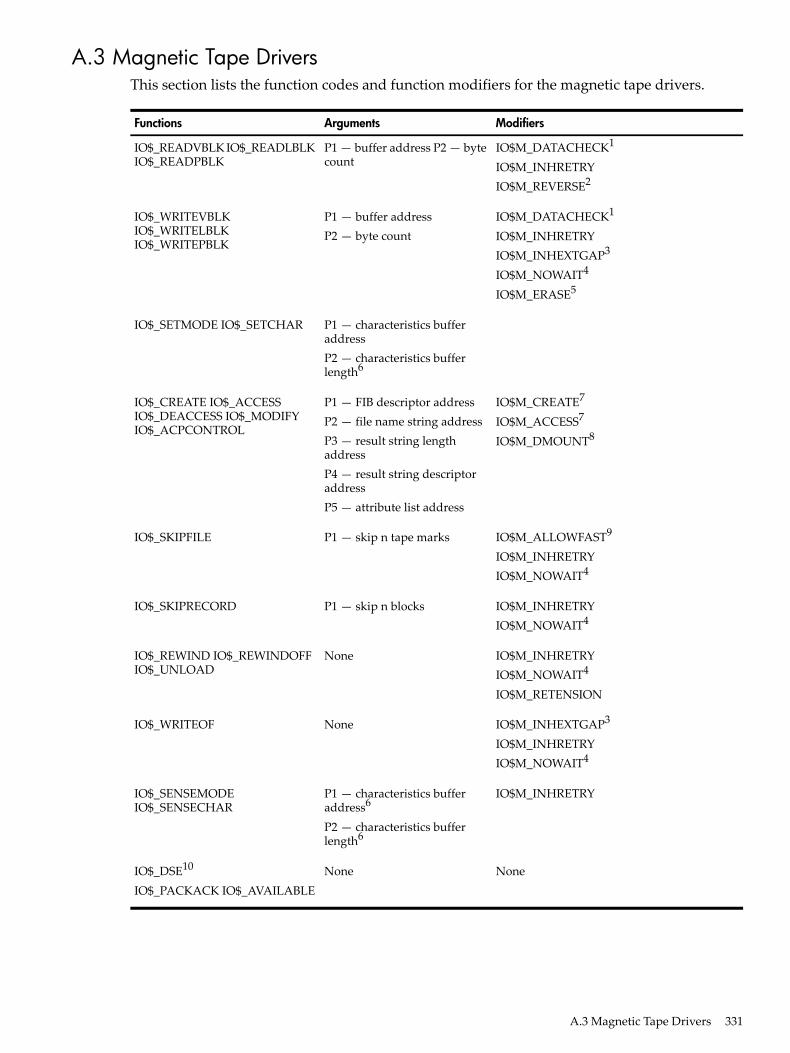
A.3 Magnetic Tape DriversThis section lists the function codes and function modifiers for the magnetic tape drivers.
ModifiersArgumentsFunctions
IO$M_DATACHECK1
IO$M_INHRETRYIO$M_REVERSE2
P1 — buffer address P2 — bytecount
IO$_READVBLK IO$_READLBLKIO$_READPBLK
IO$M_DATACHECK1
IO$M_INHRETRYIO$M_INHEXTGAP3
IO$M_NOWAIT4
IO$M_ERASE5
P1 — buffer addressP2 — byte count
IO$_WRITEVBLKIO$_WRITELBLKIO$_WRITEPBLK
P1 — characteristics bufferaddressP2 — characteristics bufferlength6
IO$_SETMODE IO$_SETCHAR
IO$M_CREATE7
IO$M_ACCESS7
IO$M_DMOUNT8
P1 — FIB descriptor addressP2 — file name string addressP3 — result string lengthaddressP4 — result string descriptoraddressP5 — attribute list address
IO$_CREATE IO$_ACCESSIO$_DEACCESS IO$_MODIFYIO$_ACPCONTROL
IO$M_ALLOWFAST9
IO$M_INHRETRYIO$M_NOWAIT4
P1 — skip n tape marksIO$_SKIPFILE
IO$M_INHRETRYIO$M_NOWAIT4
P1 — skip n blocksIO$_SKIPRECORD
IO$M_INHRETRYIO$M_NOWAIT4
IO$M_RETENSION
NoneIO$_REWIND IO$_REWINDOFFIO$_UNLOAD
IO$M_INHEXTGAP3
IO$M_INHRETRYIO$M_NOWAIT4
NoneIO$_WRITEOF
IO$M_INHRETRYP1 — characteristics bufferaddress6
P2 — characteristics bufferlength6
IO$_SENSEMODEIO$_SENSECHAR
NoneNoneIO$_DSE10
IO$_PACKACK IO$_AVAILABLE
A.3 Magnetic Tape Drivers 331

1 Not for TS04 and TU802 Not for TK503 Only for TE16, TU45, and TU774 Only for TU81-Plus drives5 IO$M_REASE takes no arguments; only for IO$_WRITEBLK and IO$_WRITEPBLK on TMSCP drives.6 Only for TMSCP drives7 Only for IO$_CREATE and IO$_ACCESS8 Only for IO$_ACPCONTROL9 Only for local SCSI drives10 Only for TU78, TU81, TA81, and TA78
QIO Status Returns
SS$_CTRLERRSS$_CANCELSS$_ABORT
SS$_DEVOFFLINESS$_DATAOVERUNSS$_DATACHECK
SS$_ENDOFTAPESS$_ENDOFFILESS$_DRVERR
SS$_ILLIOFUNCSS$_FORMATSS$_ENDOFVOLUME
SS$_NORMALSS$_NONEXDRVSS$_MEDOFL
SS$_SERIOUSEXCPSS$_PARITYSS$_OPINCOMPL
SS$_VOLINVSS$_UNSAFESS$_TIMEOUT
SS$_WRITLCK
A.4 Mailbox DriverThis section lists the function codes and function modifiers for the mailbox driver.
ModifiersArgumentsFunctions
IO$M_NOW IO$M_NORSWAIT1
IO$M_READERCHECK1
IO$M_WRITERCHECK 2
IO$M_STREAM2
P1 — buffer addressP2 — buffer size
IO$_READVBLK IO$_READLBLK IO$_READPBLKIO$_WRITEVBLK IO$_WRITELBLK IO$_WRITEPBLK
IO$M_NOWIO$M_READERCHECKIO$M_STREAM
NoneIO$_WRITEOF
NoneP1 — AST addressP2 — AST parameterP3 — access mode
IO$_SETMODE!IO$M_READATTNIO$_SETMODE!IO$M_WRTATTNIO$_SETMODE!IO$MB_ROOM_NOTIFY
NoneNoneIO$_SETMODE!IO$M_READERWAIT3
IO$_SETMODE!IO$M_WRITERWAIT3
NoneP2 — volumeprotection mask
IO$_SETMODE!IO$M_SETPROT
NoneNoneIO$_SENSEMODE!IO$M_READERCHECK3
IO$_SENSEMODE!IO$M_WRITERCHECK3
332 I/O Function Codes

1 Only for write functions2 Only for read functions3 VAX specific
QIO Status Returns in R0
SS$INFMEMSS$_ILLIOFUNCSS$_EXQUOTASS$_ACCVIO
SS$_NORMALSS$_NOPRIVSS$_MBTOOSMLSS$MBFULL
IOSB Status Returns
SS$_ENDOFFILESS$_CANCELSS$_BUFFEROVFSS$_ABORT
SS$_NOWRITERSS$_NORMALSS$_NOREADER
A.5 Terminal DriverThis section lists the function codes and function modifiers for the terminal driver.
ModifiersArgumentsFunctions
IO$M_NOECHOIO$M_CVTLOWIO$M_NOFILTRIO$M_TIMED IO$M_PURGEIO$M_DSABLMBX IO$M_TRMNOECHOIO$M_ESCAPE
P1 — buffer addressP2 — buffer sizeP3 — timeoutP4 — read terminator blockaddressP5 — prompt string bufferaddressP6 — prompt string buffer size1
IO$_READVBLK IO$_READLBLKIO$_READPROMPT
IO$M_EXTEND2P1 — buffer addressP2 — buffer sizeP3 — access mode to probeitemlistP4 — (zero)P5 — itemlist buffer addressP6 — itemlist buffer size
IO$_READVBLK
IO$M_CANCTRLO IO$M_ENABLMBXIO$M_NOFORMATIO$M_REFRESH IO$M_BREAKTHRU
P1 — buffer addressP2 — buffer sizeP3 — (ignored)P4 — carriage control specifier3
IO$_WRITEVBLK IO$_WRITELBLKIO$_WRITEPBLK
P1 — characteristics bufferaddressP2 — characteristics buffer sizeP3 — speed specifierP4 — fill specifierP5 — parity flags
IO$_SETMODE IO$_SETCHAR
IO$M_HANGUPNoneIO$_SETMODE IO$_SETCHAR
IO$M_BRDCSTP1 — buffer addressP2 — buffer size
IO$_SETMODE
A.5 Terminal Driver 333
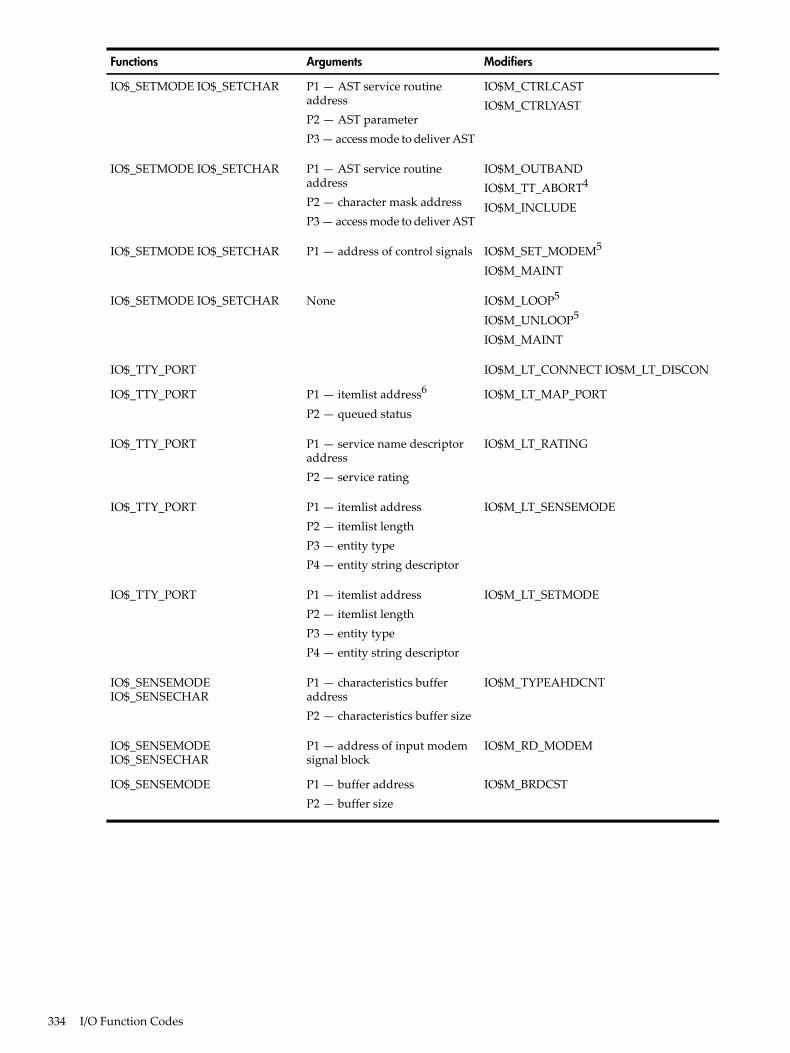
ModifiersArgumentsFunctions
IO$M_CTRLCASTIO$M_CTRLYAST
P1 — AST service routineaddressP2 — AST parameterP3 — access mode to deliver AST
IO$_SETMODE IO$_SETCHAR
IO$M_OUTBANDIO$M_TT_ABORT4
IO$M_INCLUDE
P1 — AST service routineaddressP2 — character mask addressP3 — access mode to deliver AST
IO$_SETMODE IO$_SETCHAR
IO$M_SET_MODEM5
IO$M_MAINTP1 — address of control signalsIO$_SETMODE IO$_SETCHAR
IO$M_LOOP5
IO$M_UNLOOP5
IO$M_MAINT
NoneIO$_SETMODE IO$_SETCHAR
IO$M_LT_CONNECT IO$M_LT_DISCONIO$_TTY_PORT
IO$M_LT_MAP_PORTP1 — itemlist address6
P2 — queued statusIO$_TTY_PORT
IO$M_LT_RATINGP1 — service name descriptoraddressP2 — service rating
IO$_TTY_PORT
IO$M_LT_SENSEMODEP1 — itemlist addressP2 — itemlist lengthP3 — entity typeP4 — entity string descriptor
IO$_TTY_PORT
IO$M_LT_SETMODEP1 — itemlist addressP2 — itemlist lengthP3 — entity typeP4 — entity string descriptor
IO$_TTY_PORT
IO$M_TYPEAHDCNTP1 — characteristics bufferaddressP2 — characteristics buffer size
IO$_SENSEMODEIO$_SENSECHAR
IO$M_RD_MODEMP1 — address of input modemsignal block
IO$_SENSEMODEIO$_SENSECHAR
IO$M_BRDCSTP1 — buffer addressP2 — buffer size
IO$_SENSEMODE
334 I/O Function Codes
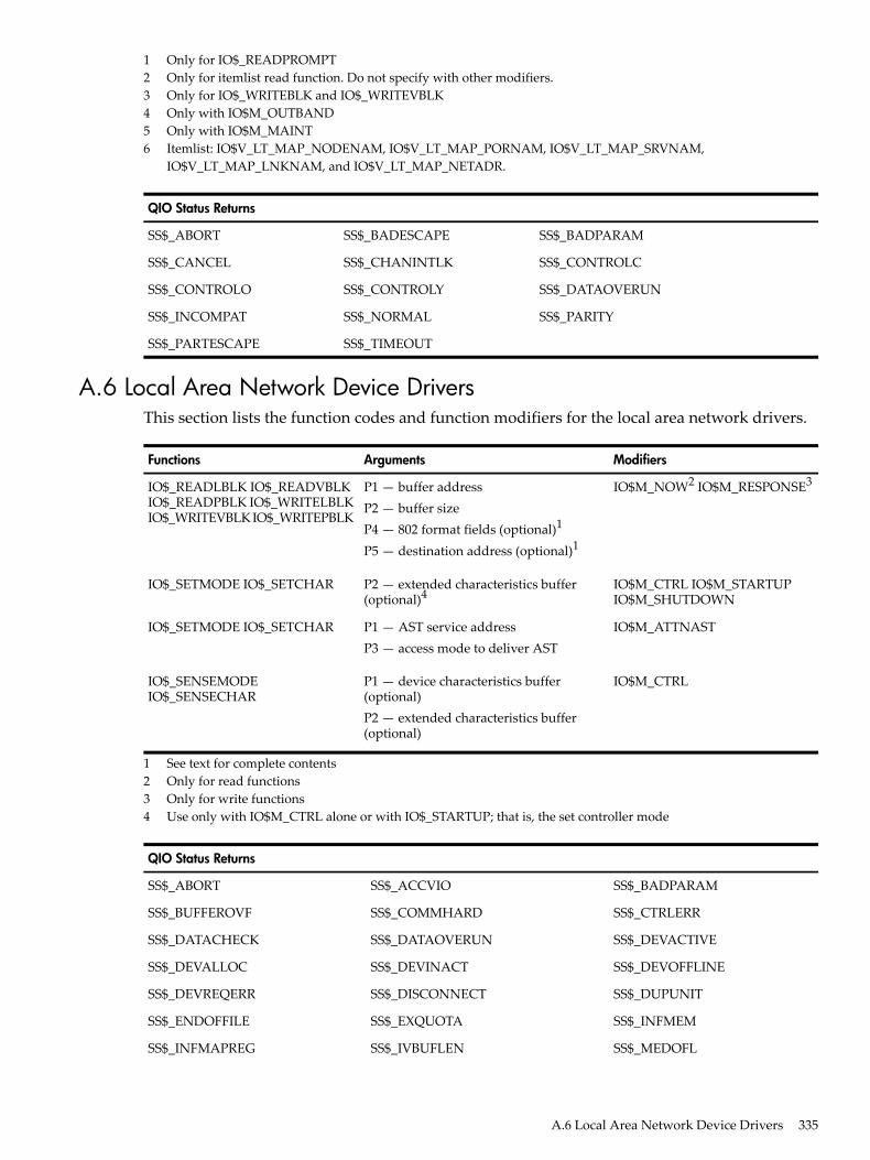
1 Only for IO$_READPROMPT2 Only for itemlist read function. Do not specify with other modifiers.3 Only for IO$_WRITEBLK and IO$_WRITEVBLK4 Only with IO$M_OUTBAND5 Only with IO$M_MAINT6 Itemlist: IO$V_LT_MAP_NODENAM, IO$V_LT_MAP_PORNAM, IO$V_LT_MAP_SRVNAM,
IO$V_LT_MAP_LNKNAM, and IO$V_LT_MAP_NETADR.
QIO Status Returns
SS$_BADPARAMSS$_BADESCAPESS$_ABORT
SS$_CONTROLCSS$_CHANINTLKSS$_CANCEL
SS$_DATAOVERUNSS$_CONTROLYSS$_CONTROLO
SS$_PARITYSS$_NORMALSS$_INCOMPAT
SS$_TIMEOUTSS$_PARTESCAPE
A.6 Local Area Network Device DriversThis section lists the function codes and function modifiers for the local area network drivers.
ModifiersArgumentsFunctions
IO$M_NOW2 IO$M_RESPONSE3P1 — buffer addressP2 — buffer sizeP4 — 802 format fields (optional)1
P5 — destination address (optional)1
IO$_READLBLK IO$_READVBLKIO$_READPBLK IO$_WRITELBLKIO$_WRITEVBLK IO$_WRITEPBLK
IO$M_CTRL IO$M_STARTUPIO$M_SHUTDOWN
P2 — extended characteristics buffer(optional)4
IO$_SETMODE IO$_SETCHAR
IO$M_ATTNASTP1 — AST service addressP3 — access mode to deliver AST
IO$_SETMODE IO$_SETCHAR
IO$M_CTRLP1 — device characteristics buffer(optional)P2 — extended characteristics buffer(optional)
IO$_SENSEMODEIO$_SENSECHAR
1 See text for complete contents2 Only for read functions3 Only for write functions4 Use only with IO$M_CTRL alone or with IO$_STARTUP; that is, the set controller mode
QIO Status Returns
SS$_BADPARAMSS$_ACCVIOSS$_ABORT
SS$_CTRLERRSS$_COMMHARDSS$_BUFFEROVF
SS$_DEVACTIVESS$_DATAOVERUNSS$_DATACHECK
SS$_DEVOFFLINESS$_DEVINACTSS$_DEVALLOC
SS$_DUPUNITSS$_DISCONNECTSS$_DEVREQERR
SS$_INFMEMSS$_EXQUOTASS$_ENDOFFILE
SS$_MEDOFLSS$_IVBUFLENSS$_INFMAPREG
A.6 Local Area Network Device Drivers 335

QIO Status Returns
SS$_OPINCOMPLSS$_NORMALSS$_NOPRIV
SS$_TOOMUCHDATASS$_TIMEOUT
A.7 Fast I/O Function Codes and ModifiersThis section lists the function codes and parameters for the $IO_SETUP system service.
ArgumentsFunctions
bufobj - user's bufferiosobj — I/O Status Area (IOSA)astadr — Completion AST routineflags — longword maskreturn_fandle — fandle address
IO$_READVBLKIO$_READLBLKIO$_WRITEVBLKIO$_WRITELBLK
A.8 Fast Path Function Code and ModifiersThis section lists the function code and function modifiers for Fast Path.
ModifiersArgumentFunction
IO$M_PREFERRED_CPU IO$M_SYS_ASSIGNABLEP1 — CPU mask NoneIO$_SETPRFPATH
336 I/O Function Codes
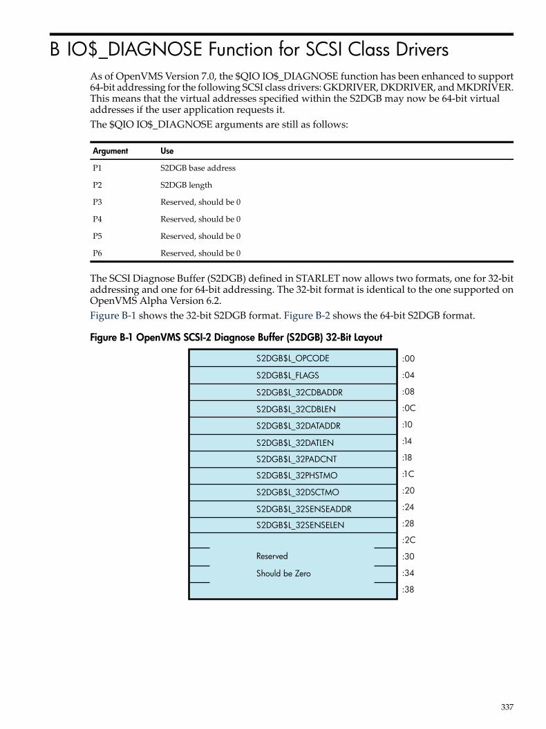
B IO$_DIAGNOSE Function for SCSI Class DriversAs of OpenVMS Version 7.0, the $QIO IO$_DIAGNOSE function has been enhanced to support64-bit addressing for the following SCSI class drivers: GKDRIVER, DKDRIVER, and MKDRIVER.This means that the virtual addresses specified within the S2DGB may now be 64-bit virtualaddresses if the user application requests it.The $QIO IO$_DIAGNOSE arguments are still as follows:
UseArgument
S2DGB base addressP1
S2DGB lengthP2
Reserved, should be 0P3
Reserved, should be 0P4
Reserved, should be 0P5
Reserved, should be 0P6
The SCSI Diagnose Buffer (S2DGB) defined in STARLET now allows two formats, one for 32-bitaddressing and one for 64-bit addressing. The 32-bit format is identical to the one supported onOpenVMS Alpha Version 6.2.Figure B-1 shows the 32-bit S2DGB format. Figure B-2 shows the 64-bit S2DGB format.
Figure B-1 OpenVMS SCSI-2 Diagnose Buffer (S2DGB) 32-Bit Layout
S2DGB$L_OPCODE
S2DGB$L_FLAGS
S2DGB$L_32CDBADDR
S2DGB$L_32CDBLEN
S2DGB$L_32DATADDR
S2DGB$L_32DATLEN
S2DGB$L_32PADCNT
S2DGB$L_32PHSTMO
S2DGB$L_32DSCTMO
S2DGB$L_32SENSEADDR
S2DGB$L_32SENSELEN
Reserved
Should be Zero
:00
:04
:08
:0C
:10
:14
:18
:1C
:20
:24
:28
:2C
:30
:34
:38
337

Figure B-2 OpenVMS SCSI-2 Diagnose Buffer (S2DGB) 64-Bit Layout
S2DGB$L_OPCODE
S2DGB$L_FLAGS
S2DGB$L_64CDBADDR
S2DGB$L_64DATADDR
S2DGB$L_64PHSTMO
S2DGB$L_64PADCNT
S2DGB$L_64DSCTMO
S2DGB$L_64SENSEADDR
S2DGB$L_64SENSELEN
S2DGB$L_64SCDBLEN
S2DGB$L_64DATLEN
Reserved. Should be Zero
:00
:04
:08
:0C
:10
:14
:18
:1C
:20
:24
:28
:2C
:30
:34
:38
A user application must specify which one of the two S2DGB formats is to be used by passing aformat value in S2DGB$L_OPCODE. Specifically, S2DGB$L_OPCODE must be assigned a valueof either OP_XCDB32 (= 1) to request 32-bit format, or OP_XCDB64 (= 2) to request 64-bit format.Once the value of OP_XCDB64 has been specified, the user application is obligated to use the64-bit S2DGB format and, in particular, to use the 64-bit names for S2DGB fields as describedbelow. Likewise, an opcode value of OP_XCDB32 obligates the user application to use the 32-bitnames for the fields.The correct length of the structure is defined by the constant S2DGB$K_XCDB32_LENGTH(value: 60-decimal), as well as by the constant S2DGB$K_XCDB64_LENGTH (value: 60-decimal).The fields in the S2DGB are in the sections that follow. Whenever a field has two different namesfor the 32-bit and 64-bit cases, the 32-bit name is given first, and the 64-bit name is given after itin parentheses. Also, except for fields that contain addresses, all fields are unsigned longwords.S2DGB$L_OPCODEThis field should contain either S2DGB$K_OP_XCDB32 or S2DGB$K_OP_XCDB64, dependingon whether the user application intends to supply 32-bit virtual addresses or 64-bit virtualaddresses, respectively, in the other fields of the S2DGB.S2DGB$L_FLAGSThis field should contain the bit fields shown in the following table. Note that these bit definitionsstart at bit 0 and omit no bits. This is required for compatibility with the IO$_DIAGNOSE interfaceavailable in OpenVMS Alpha Version 6.1 and earlier.
Table B-1 S2DGB$L_FLAGS Bit Fields
DescriptionBit Field
This bit should be 1 if the operation being performed is a read. If the operationis a write, this bit should be 0.
S2DGB$V_READ
This bit should contain the DiscPriv bit value to be used in the IDENTIFYmessage sent with this operation. If S2DGB$V_TAGGED_REQ is 1, then thisbit is ignored. Note that S2DGB$V_DISCPRIV may be ignored by some portsunconditionally.
S2DGB$V_DISCPRIV
This bit is ignored because its value is beyond the control of the user inSCSI-2 drivers.
S2DGB$V_SYNCHRONOUS
338 IO$_DIAGNOSE Function for SCSI Class Drivers
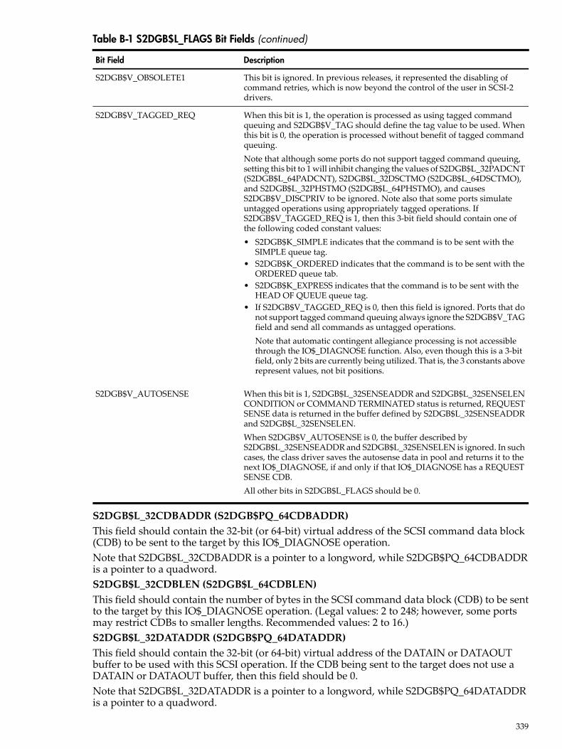
Table B-1 S2DGB$L_FLAGS Bit Fields (continued)
DescriptionBit Field
This bit is ignored. In previous releases, it represented the disabling ofcommand retries, which is now beyond the control of the user in SCSI-2drivers.
S2DGB$V_OBSOLETE1
When this bit is 1, the operation is processed as using tagged commandqueuing and S2DGB$V_TAG should define the tag value to be used. Whenthis bit is 0, the operation is processed without benefit of tagged commandqueuing.Note that although some ports do not support tagged command queuing,setting this bit to 1 will inhibit changing the values of S2DGB$L_32PADCNT(S2DGB$L_64PADCNT), S2DGB$L_32DSCTMO (S2DGB$L_64DSCTMO),and S2DGB$L_32PHSTMO (S2DGB$L_64PHSTMO), and causesS2DGB$V_DISCPRIV to be ignored. Note also that some ports simulateuntagged operations using appropriately tagged operations. IfS2DGB$V_TAGGED_REQ is 1, then this 3-bit field should contain one ofthe following coded constant values:• S2DGB$K_SIMPLE indicates that the command is to be sent with the
SIMPLE queue tag.• S2DGB$K_ORDERED indicates that the command is to be sent with the
ORDERED queue tab.• S2DGB$K_EXPRESS indicates that the command is to be sent with the
HEAD OF QUEUE queue tag.• If S2DGB$V_TAGGED_REQ is 0, then this field is ignored. Ports that do
not support tagged command queuing always ignore the S2DGB$V_TAGfield and send all commands as untagged operations.Note that automatic contingent allegiance processing is not accessiblethrough the IO$_DIAGNOSE function. Also, even though this is a 3-bitfield, only 2 bits are currently being utilized. That is, the 3 constants aboverepresent values, not bit positions.
S2DGB$V_TAGGED_REQ
When this bit is 1, S2DGB$L_32SENSEADDR and S2DGB$L_32SENSELENCONDITION or COMMAND TERMINATED status is returned, REQUESTSENSE data is returned in the buffer defined by S2DGB$L_32SENSEADDRand S2DGB$L_32SENSELEN.When S2DGB$V_AUTOSENSE is 0, the buffer described byS2DGB$L_32SENSEADDR and S2DGB$L_32SENSELEN is ignored. In suchcases, the class driver saves the autosense data in pool and returns it to thenext IO$_DIAGNOSE, if and only if that IO$_DIAGNOSE has a REQUESTSENSE CDB.All other bits in S2DGB$L_FLAGS should be 0.
S2DGB$V_AUTOSENSE
S2DGB$L_32CDBADDR (S2DGB$PQ_64CDBADDR)This field should contain the 32-bit (or 64-bit) virtual address of the SCSI command data block(CDB) to be sent to the target by this IO$_DIAGNOSE operation.Note that S2DGB$L_32CDBADDR is a pointer to a longword, while S2DGB$PQ_64CDBADDRis a pointer to a quadword.S2DGB$L_32CDBLEN (S2DGB$L_64CDBLEN)This field should contain the number of bytes in the SCSI command data block (CDB) to be sentto the target by this IO$_DIAGNOSE operation. (Legal values: 2 to 248; however, some portsmay restrict CDBs to smaller lengths. Recommended values: 2 to 16.)S2DGB$L_32DATADDR (S2DGB$PQ_64DATADDR)This field should contain the 32-bit (or 64-bit) virtual address of the DATAIN or DATAOUTbuffer to be used with this SCSI operation. If the CDB being sent to the target does not use aDATAIN or DATAOUT buffer, then this field should be 0.Note that S2DGB$L_32DATADDR is a pointer to a longword, while S2DGB$PQ_64DATADDRis a pointer to a quadword.
339

S2DGB$L_32DATLEN (S2DGB$L_64DATLEN)This field should contain the number of bytes in the DATAIN or DATAOUT buffer associatedwith this operation. If the CDB being sent to the target does not use a DATAIN or DATAOUTbuffer, then this field should be 0. (Legal values: 0 to UCB$L_MAXBCNT. Recommended values:0 to 65,536. All ports are required to support at least 65,536 byte data transfers.)S2DGB$L_32PADCNT (S2DGB$L_64PADCNT)This field should contain the number of padding DATAIN or DATAOUT bytes required by thisoperation. If S2DGB$V_TAGGED_REQ is 1, then the PAD count value is not its default value.(Legal values: 0 to the maximum number of bytes in a disk block on this system minus one.Current legal values: 0 to 511.)S2DGB$L_32PHSTMO (S2DGB$L_64PHSTMO)This field should contain the number of seconds that the port driver should wait for a phasetransition to occur or for delivery of an expected interrupt. If S2DGB$V_ TAGGED_REQ is 1 orthis field contains a 0 or 1, then the current phase transition timeout setting will not be changed.(Legal values: 0 to 65,535 (about 18 hours).)S2DGB$L_32DSCTMO (S2DGB$L_64DSCTMO)This field should contain the number of seconds that the port driver should wait for a disconnectedtransaction to reconnect. If S2DGB$V_TAGGED_REQ is 1 or this field contains a 0 or 1, then thecurrent disconnect timeout setting will not be changed. (Legal values: 0 to 65,535 (about 18hours).)S2DGB$L_32SENSEADDR (S2DGB$PQ_64SENSEADDR)If S2DGB$V_AUTOSENSE is 1, then this field should contain the 32-bit (or 64-bit) virtual addressof the sense buffer to be used by this SCSI operation. If S2DGB$V_AUTOSENSE is 0, this fieldis ignored.Note that S2DGB$L_32SENSEADDR is a pointer to a longword, while S2DGB$PQ_64SENSEADDRis a pointer to a quadword.S2DGB$L_32SENSELEN (S2DGB$L_64SENSELEN)If S2DGB$V_AUTOSENSE is 1, then this field should contain the number of bytes in the sensebuffer associated with this operation. (Legal values: 0 to 255. Note that a value of 0 instructs theclass driver to discard any sense data received. Recommended value: 18. Some ports may restrictthe number of sense bytes to 18.) If S2DGB$V_AUTOSENSE is 0, this field is ignored.The following example shows how to set up a 64-bit S2DGB:#include /* Define S2DGB */#include _pointers.h> /* Define VOID_PQ */
S2DGB diag_desc;
/* Set up some default S2DGB descriptor values */
diag_desc.s2dgb$l_opcode = OP_XCDB64 /* Use 64-bits */ diag_desc.s2dgb$l_flags = (S2DGB$M_READ | /* Flags*/ S2DGB$M_TAGGED_REQ | S2DGB$M_AUTOSENSE); diag_desc.s2dgb$v_tag = S2DGB$K_SIMPLE; /* SIMPLE que tag */ diag_desc.s2dgb$pq_64cdbaddr = (VOID_PQ)([0]);/* Command addr */ diag_desc.s2dgb$l_64cdblen = 6; /* Command length */ diag_desc.s2dgb$pq_64dataddr = (VOID_PQ)([0]);/* Data addr */ diag_desc.s2dgb$l_64datlen = 20; /* Data length */ diag_desc.s2dgb$l_64padcnt = 0; /* Pad length */ diag_desc.s2dgb$l_64phstmo = 20; /* Phase timeout */ diag_desc.s2dgb$l_64dsctmo = 10; /* Disc timeout */ diag_desc.s2dgb$pq_64senseaddr = (VOID_PQ)([0]);/* Autosense addr */ diag_desc.s2dgb$l_64senselen = 255; /* Sense length */ diag_desc.s2dgb$l_reserved_1 = 0; /* Reserved */ . .
340 IO$_DIAGNOSE Function for SCSI Class Drivers
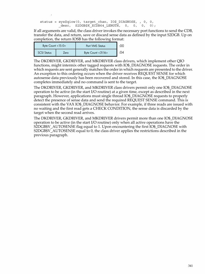
.
status = sys$qiow(0, target_chan, IO$_DIAGNOSE, , 0, 0, _desc, S2DGB$K_XCDB64_LENGTH, 0, 0, 0, 0);
If all arguments are valid, the class driver invokes the necessary port functions to send the CDB,transfer the data, and return, save or discard sense data as defined by the input S2DGB. Up oncompletion, the return IOSB has the following format:
Byte Count <15:0>
Byte Count <31:16>SCSI Status Zero
Port VMS Status :00
:04
The DKDRIVER, GKDRIVER, and MKDRIVER class drivers, which implement other QIOfunctions, might intermix other tagged requests with IO$_DIAGNOSE requests. The order inwhich requests are sent generally matches the order in which requests are presented to the driver.An exception to this ordering occurs when the driver receives REQUEST SENSE for whichautosense data previously has been recovered and stored. In this case, the IO$_DIAGNOSEcompletes immediately and no command is sent to the target.The DKDRIVER, GKDRIVER, and MKDRIVER class drivers permit only one IO$_DIAGNOSEoperation to be active (in the start I/O routine) at a given time, except as described in the nextparagraph. However, applications must single thread IO$_DIAGNOSE requests to properlydetect the presence of sense data and send the required REQUEST SENSE command. This isconsistent with the VAX IO$_DIAGNOSE behavior. For example, if three reads are issued withno waiting and the first read gets a CHECK CONDITION, the sense data is discarded by thetarget when the second read arrives.The DKDRIVER, GKDRIVER, and MKDRIVER drivers permit more than one IO$_DIAGNOSEoperation to be active (in the start I/O routine) only when all active operations have theS2DGB$V_AUTOSENSE flag equal to 1. Upon encountering the first IO$_DIAGNOSE withS2DGB$V_AUTOSENSE equal to 0, the class driver applies the restrictions described in theprevious paragraph.
341

342

C DEC Multinational Character Set and Terminal EscapeSequences/Modes
This appendix includes tables for the DEC Multinational character set and for terminal escapesequences and modes.
C.1 DEC Multinational Character SetTable C-1 lists the DEC Multinational character set. The DEC Multinational character set is an8-bit character set with 256 characters. The first 128 characters in the set correspond to the ASCIIcharacter set. The VAX EDT Reference Manual lists the graphics for these characters and describeshow to enter them from various types of terminals.
Table C-1 DEC Multinational Character Set
DescriptionChar or Abbrev.Decimal CodeOctal CodeHex Code
ASCII Control Characters1
null characterNUL00000000
start of heading (Ctrl/A)SOH00100101
start of text (Ctrl/B)STX00200202
end of text (Ctrl/C)ETX00300303
end of transmission (Ctrl/D)EOT00400404
enquiry (Ctrl/E)ENQ00500505
acknowledge (Ctrl/F)ACK00600606
bell (Ctrl/G)BEL00700707
backspace (Ctrl/H)BS00801008
horizontal tabulation (Ctrl/I)HT00901109
line feed (Ctrl/J)LF0100120A
vertical tabulation (Ctrl/K)VT0110130B
form feed (Ctrl/L)FF0120140C
carriage return (Ctrl/M)CR0130150D
shift out (Ctrl/N)SO0140160E
shift in (Ctrl/O)SI0150170F
data link escape (Ctrl/P)DLE01602010
device control 1 (Ctrl/Q)DC101702111
device control 2 (Ctrl/R)DC201802212
device control 3 (Ctrl/S)DC301902313
device control 4 (Ctrl/T)DC402002414
negative acknowledge (Ctrl/U)NAK02102515
synchronous idle (Ctrl/V)SYN02202616
end of transmission block (Ctrl/W)ETB02302717
cancel (Ctrl/X)CAN02403018
end of medium (Ctrl/Y)EM02503119
C.1 DEC Multinational Character Set 343

Table C-1 DEC Multinational Character Set (continued)
DescriptionChar or Abbrev.Decimal CodeOctal CodeHex Code
substitute (Ctrl/Z)SUB0260321A
escapeESC0270331B
file separatorFS0280341C
group separatorGS0290351D
record separatorRS0300361E
unit separatorUS0310371F
ASCII Special and Numeric Characters
spaceSP03204020
exclamation point!03304121
quotation marks (double quote)'03404222
number sign#03504323
dollar sign$03604424
percent sign%03704525
ampersand&03804626
apostrophe (single quote)'03904727
opening parenthesis(04005028
closing parenthesis)04105129
asterisk*0420522A
plus+0430532B
comma,0440542C
hyphen or minus—0450552D
period or decimal point.0460562E
slash/0470572F
zero004806030
one104906131
two205006232
three305106333
four405206434
five505306535
six605406636
seven705506737
eight805607038
nine905707139
colon:0580723A
semicolon;0590733B
less than<0600743C
344 DEC Multinational Character Set and Terminal Escape Sequences/Modes

Table C-1 DEC Multinational Character Set (continued)
DescriptionChar or Abbrev.Decimal CodeOctal CodeHex Code
equals=0610753D
greater than>0620763E
question mark?0630773F
ASCII Alphabetic Characters
commercial at sign@06410040
uppercase AA06510141
uppercase BB06610242
uppercase CC06710343
uppercase DD06810444
uppercase EE06910545
uppercase FF07010646
uppercase GG07110747
uppercase HH07211048
uppercase II07311149
uppercase JJ0741124A
uppercase KK0751134B
uppercase LL0761144C
uppercase MM0771154D
uppercase NN0781164E
uppercase OO0791174F
uppercase PP08012050
uppercase QQ08112151
uppercase RR08212252
uppercase SS08312353
uppercase TT08412454
uppercase UU08512555
uppercase VV08612656
uppercase WW08712757
uppercase XX08813058
uppercase YY08913159
uppercase ZZ0901325A
left bracket[0911335B
backslash\0921345C
right bracket]0931355D
circumflex^0941365E
underscore_0951375F
C.1 DEC Multinational Character Set 345

Table C-1 DEC Multinational Character Set (continued)
DescriptionChar or Abbrev.Decimal CodeOctal CodeHex Code
grave accent`09614060
lowercase aa09714161
lowercase bb09814262
lowercase cc09914363
lowercase dd10014464
lowercase ee10114565
lowercase ff10214666
lowercase gg10314767
lowercase hh10415068
lowercase ii10515169
lowercase jj1061526A
lowercase kk1071536B
lowercase ll1081546C
lowercase mm1091556D
lowercase nn1101566E
lowercase oo1111576F
lowercase pp11216070
lowercase qq11316171
lowercase rr11416272
lowercase ss11516373
lowercase tt11616474
lowercase uu11716575
lowercase vv11816676
lowercase ww11916777
lowercase xx12017078
lowercase yy12117179
lowercase zz1221727A
left brace{1231737B
vertical line|1241747C
right brace (ALTMODE)}1251757D
tilde (ALTMODE)~1261767E
rubout (DELETE)DEL1271777F
[reserved]—12820080
[reserved]—12920181
[reserved]—13020282
[reserved]—13120383
346 DEC Multinational Character Set and Terminal Escape Sequences/Modes

Table C-1 DEC Multinational Character Set (continued)
DescriptionChar or Abbrev.Decimal CodeOctal CodeHex Code
indexIND13220484
next lineNEL13320585
start of selected areaSSA13420686
end of started areaESA13520787
horizontal tab setHTS13621088
horizontal tab set with justificationHTJ13721189
vertical tab setVTS1382128A
partial line downPLD1392138B
partial line upPLU1402148C
reverse indexRI1412158D
single shift 2SS21422168E
single shift 3SS31432178F
device control stringDCS14422090
private use 1PU114522191
private use 2PU214622292
set transmit stateSTS14722393
cancel characterCCH14822494
message waitingMW14922595
start of protected areaSPA15022696
end of protected areaEPA15122797
[reserved]—15223098
[reserved]—15323199
[reserved]—1542329A
control sequence introducerCSI1552339B
string terminatorST1562349C
operating system commandOSC1572359D
privacy messagePM1582369E
applicationAPC1592379F
[reserved]—160240A0
inverted exclamation point¡161241A1
cent sign¢162242A2
pound sign£163243A3
[reserved]—164244A4
yen sign¥165245A5
[reserved]—166246A6
section sign§167247A7
C.1 DEC Multinational Character Set 347

Table C-1 DEC Multinational Character Set (continued)
DescriptionChar or Abbrev.Decimal CodeOctal CodeHex Code
general currency sign¤168250A8
copyright sign©169251A9
feminine ordinal indicatorª170252AA
angle quotation mark left<<171253AB
[reserved]—172254AC
[reserved]—173255AD
[reserved]—174256AE
[reserved]—175257AF
degree sign°176260B0
plus/minus sign±177261B1
superscript 2²178262B2
superscript 3³179263B3
[reserved]—180264B4
micro signµ181265B5
paragraph sign, pilcrow¶182266B6
middle dotplaceholder183267B7
[reserved]—184270B8
superscript 1¹185271B9
masculine ordinal indicatorº186272BA
angle quotation mark right>>187273BB
fraction one-quarter1/4188274BC
fraction one-half1/2189275BD
[reserved]—190276BE
inverted question mark¿191277BF
uppercase A with grave accentÀ192300C0
uppercase A with acute accentÁ193301C1
uppercase A with circumflexÂ194302C2
uppercase A with tildeÃ195303C3
uppercase A with umlaut (diaeresis)Ä196304C4
uppercase A with ringÅ197305C5
uppercase AE diphthongAE198306C6
uppercase C with cedillaÇ199307C7
uppercase E with grave accentÈ200310C8
uppercase E with acute accentÉ201311C9
uppercase E with circumflexÊ202312CA
uppercase E with umlaut (diaeresis)Ë203313CB
348 DEC Multinational Character Set and Terminal Escape Sequences/Modes
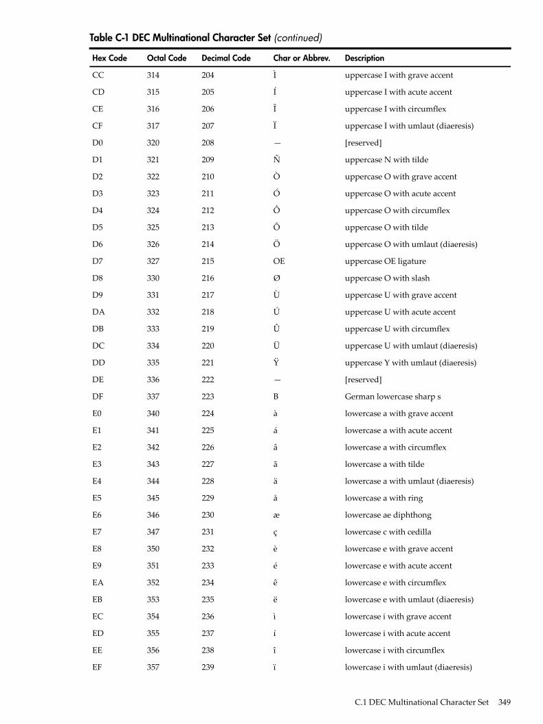
Table C-1 DEC Multinational Character Set (continued)
DescriptionChar or Abbrev.Decimal CodeOctal CodeHex Code
uppercase I with grave accentÌ204314CC
uppercase I with acute accentÍ205315CD
uppercase I with circumflexÎ206316CE
uppercase I with umlaut (diaeresis)Ï207317CF
[reserved]—208320D0
uppercase N with tildeÑ209321D1
uppercase O with grave accentÒ210322D2
uppercase O with acute accentÓ211323D3
uppercase O with circumflexÔ212324D4
uppercase O with tildeÕ213325D5
uppercase O with umlaut (diaeresis)Ö214326D6
uppercase OE ligatureOE215327D7
uppercase O with slashØ216330D8
uppercase U with grave accentÙ217331D9
uppercase U with acute accentÚ218332DA
uppercase U with circumflexÛ219333DB
uppercase U with umlaut (diaeresis)Ü220334DC
uppercase Y with umlaut (diaeresis)Ÿ221335DD
[reserved]—222336DE
German lowercase sharp sB223337DF
lowercase a with grave accentà224340E0
lowercase a with acute accentá225341E1
lowercase a with circumflexâ226342E2
lowercase a with tildeã227343E3
lowercase a with umlaut (diaeresis)ä228344E4
lowercase a with ringå229345E5
lowercase ae diphthongæ230346E6
lowercase c with cedillaç231347E7
lowercase e with grave accentè232350E8
lowercase e with acute accenté233351E9
lowercase e with circumflexê234352EA
lowercase e with umlaut (diaeresis)ë235353EB
lowercase i with grave accentì236354EC
lowercase i with acute accentí237355ED
lowercase i with circumflexî238356EE
lowercase i with umlaut (diaeresis)ï239357EF
C.1 DEC Multinational Character Set 349

Table C-1 DEC Multinational Character Set (continued)
DescriptionChar or Abbrev.Decimal CodeOctal CodeHex Code
[reserved]—240360F0
lowercase n with tildeñ241361F1
lowercase o with grave accentò242362F2
lowercase o with acute accentó243363F3
lowercase o with circumflexô244364F4
lowercase o with tildeõ245365F5
lowercase o with umlaut (diaeresis)ö246366F6
lowercase oe ligatureoe247367F7
lowercase o with slashø248370F8
lowercase u with grave accentù249371F9
lowercase u with acute accentú250372FA
lowercase u with circumflexû251373FB
lowercase u with umlaut (diaeresis)ü252374FC
lowercase y with umlaut (diaeresis)ÿ253375FD
[reserved]—254376FE
[reserved]—255377FF
1 The ALTMODE and DELETE characters (decimal 125, 126, and 127) are also control characters.
C.2 Terminal Sequences and ModesTable C-2 lists the valid ANSI and DIGITAL private escape sequences for terminals that havethe TT2$M_ANSICRT, TT2$M_DECCRT, TT2$M_AVO, TT2$M_EDIT, and TT2$M_BLOCKcharacteristics (see “Escape and Control Sequences” (page 131)).Table C-2 also lists assumed and selectable ANSI modes and selectable DIGITAL private modes.Only the names of the escape sequences and modes are listed (for more information, see thespecific VT100-, VT200-, or VT300- family user's guide). Unless otherwise noted, the operationof escape sequences and modes is identical to the particular VT100-, VT200-, or VT300- familyterminals that implement these features.
Table C-2 Sequences and Modes
BLOCK1EDITAVODECCRTANSICRTValid ParametersName
ANSI-Defined Escape Sequences
xxAllCPR
xxAllCUB
xxAllCUD
xxAllCUF
xxAllCUP
xxAllCUU
xx0,3,5,6DSR
xx0,1,2ED
xx0,1,2EL
350 DEC Multinational Character Set and Terminal Escape Sequences/Modes
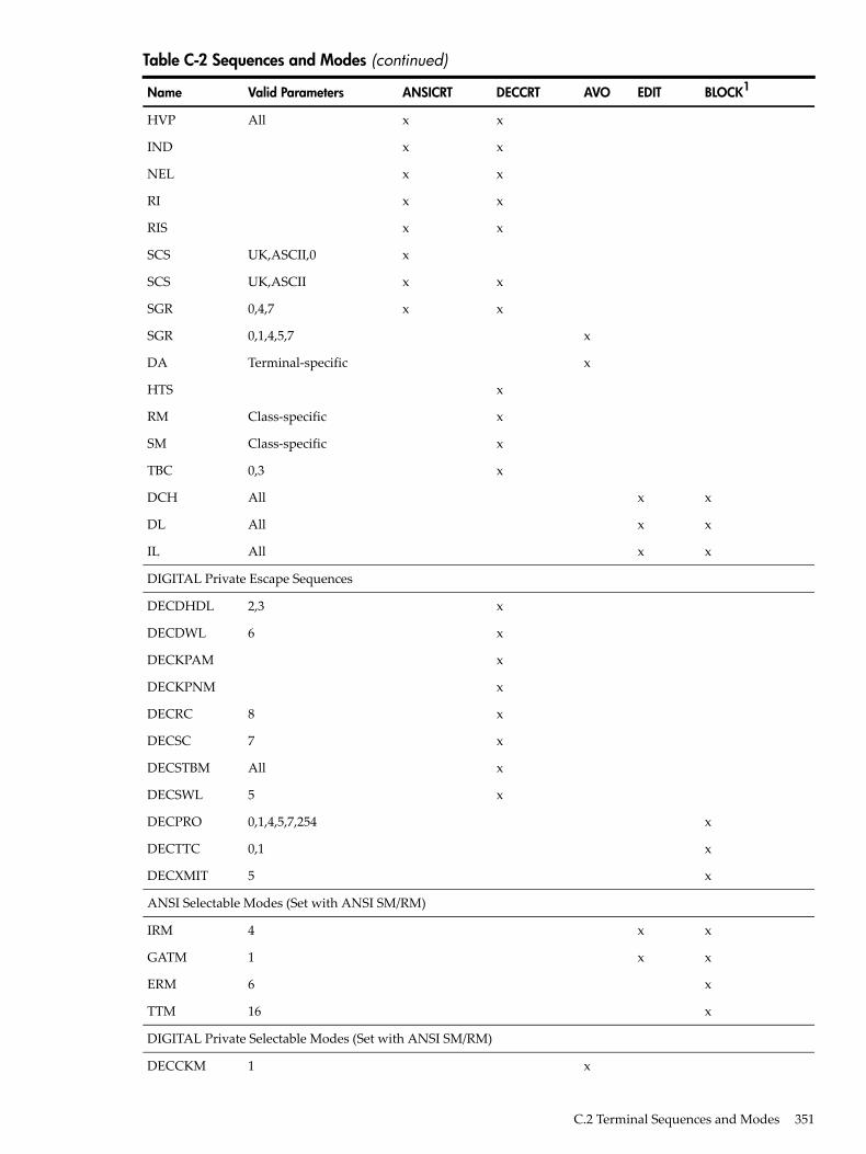
Table C-2 Sequences and Modes (continued)
BLOCK1EDITAVODECCRTANSICRTValid ParametersName
xxAllHVP
xxIND
xxNEL
xxRI
xxRIS
xUK,ASCII,0SCS
xxUK,ASCIISCS
xx0,4,7SGR
x0,1,4,5,7SGR
xTerminal-specificDA
xHTS
xClass-specificRM
xClass-specificSM
x0,3TBC
xxAllDCH
xxAllDL
xxAllIL
DIGITAL Private Escape Sequences
x2,3DECDHDL
x6DECDWL
xDECKPAM
xDECKPNM
x8DECRC
x7DECSC
xAllDECSTBM
x5DECSWL
x0,1,4,5,7,254DECPRO
x0,1DECTTC
x5DECXMIT
ANSI Selectable Modes (Set with ANSI SM/RM)
xx4IRM
xx1GATM
x6ERM
x16TTM
DIGITAL Private Selectable Modes (Set with ANSI SM/RM)
x1DECCKM
C.2 Terminal Sequences and Modes 351

Table C-2 Sequences and Modes (continued)
BLOCK1EDITAVODECCRTANSICRTValid ParametersName
x2DECANM
x3DECCOLM
x4DECSCLM
x5DECSCNM
x6DECOM
x7DECAWM
x8DECARM
x10DECEDM
x16DECEKEM
x11DECLTM
x13DECSCFDM
x14DECTEM
ANSI Assumed Modes
ResetResetCRM
ResetResetEBM2SetSetERM
ResetResetFEAM
ResetResetFETM2N/AN/AGATM
N/AN/AHEM22ResetResetIRM
ResetResetKAM
N/AN/AMATH
ResetResetPUM
N/AN/ASATM
ResetResetSRTM
ResetResetTSM2N/AN/ATTM
N/AN/AVEM
1 Terminal characteristics. Prefix is TT2$M_ .2 Selectable mode.
352 DEC Multinational Character Set and Terminal Escape Sequences/Modes

D Control Connection RoutinesThis appendix lists and describes the calling conventions for the pseudoterminal driver controlconnection routines. The routines appear in this section in alphabetical order.Table D-1 lists the control connection routines and their functions:
Table D-1 Control Connection Routines
DescriptionRoutine Name
Cancels a queued control connection read requestPTD$CANCEL
Creates a pseudoterminalPTD$CREATE
Deletes a pseudoterminalPTD$DELETE
Reads data from the pseudoterminalPTD$READ
Reads data from the pseudoterminal and waits for read tocomplete
PTD$READW
Enables or disables terminal event notification ASTsPTD$SET_EVENT_NOTIFICATION
Writes data to the pseudoterminalPTD$WRITE
D.1 PTD$CANCEL — Cancel Queued RequestCancels a queued control connection read request.
D.1.1 FormatPTD$CANCEL chan
D.1.2 ReturnsOpenVMS usage: cond_valuetype: longword (unsigned)access: write onlymechanism: by value
D.1.3 ArgumentschanOpenVMS usage: channeltype: word (unsigned)access: read onlymechanism: by valueNumber of the I/O channel assigned to the pseudoterminal. This channel is only intended to besued for PTD$XXX operations.
D.1.4 Return Values
Normal successful completion.SS$_NORMAL
Device is off line and request cannot proceed.SS$_DEVOFFLINE
Illegal channel.SS$_IVCHAN
Insufficient privilege to perform request.SS$_NOPRIV
D.1 PTD$CANCEL — Cancel Queued Request 353

D.2 PTD$CREATE — Create a PseudoterminalCreates a new pseudoterminal with a unique device name.
D.2.1 FormatPTD$CREATE chan [,acmode] [,charbuff] [,bufflen] [,astadr] [,astprm] [,ast_acmode], inadr
D.2.2 ReturnsOpenVMS usage: cond_valuetype: longword (unsigned)access: write onlymechanism: by value
D.2.3 ArgumentschanOpenVMS usage: channeltype: word (unsigned)access: write onlymechanism: by valueNumber of the channel that is assigned to the new pseudoterminal. This argument is the addressof a word into which PTD$CREATE writes the channel number. This channel is only intendedto be used for PTD$XXX operations.acmodeOpenVMS usage: access_modetype: longword (unsigned)access: read onlymechanism: by valueAccess mode to be associated with the channel. The most privileged access mode is the accessmode of the caller. I/O operations on the channel can be performed only from equal and moreprivileged access modes.charbuffOpenVMS usage: device_characteristicstype: longword (unsigned)access: read onlymechanism: by referenceAddress of buffer containing the device characteristics. This information is used to set up thepseudoterminal's initial characteristics. This buffer can be 12, 16, or 20 bytes long.Figure D-1 shows the format of this buffer:
Figure D-1 Device Characteristics Buffer
Page Width
Page Length Basic Terminal Characteristics
Extended Terminal Characteristics
Reserved
Reserved
Status
354 Control Connection Routines

bufflenOpenVMS usage: word_unsignedtype: word (unsigned)access: read onlymechanism: by valueLength of the characteristics buffer (either 12, 16, or 20 bytes). This argument is required if yousupply the charbuff argument.astadrOpenVMS usage: ast_proceduretype: procedure valueaccess: call without stack unwindingmechanism: by referenceAST service routine to be executed when the terminal connection deassigns the last channel tothe pseudoterminal. This argument is the procedure value of this routine. This is a repeatingAST and is active until the control connection deletes the pseudoterminal.astprmOpenVMS usage: user_argtype: longword (unsigned)access: read onlymechanism: by valueAST parameter to be passed to the AST service routine specified by astadr.ast_acmodeOpenVMS usage: access_modetype: longword (unsigned)access: read onlymechanism: by valueAccess mode for which the AST is to be declared. The most privileged access mode is the accessmode of the caller. The resulting mode is the access mode at which the AST is declared.inadrOpenVMS usage: address_rangetype: longword (unsigned)access: read onlymechanism: by referenceAddress of a two-longword array containing the starting and ending virtual addresses in thevirtual address space of the process (either P0 or P1 regions) to be used as I/O buffers. The arraycontains, in order, the starting and ending virtual addresses. The addresses supplied to inadrmust express an integral number of CPU-specific pages. The lower address must be on aCPU-specific page boundary, and the higher address must be one less than a CPU-specific pageboundary. Together these addresses form a range from lowest to highest bytes. The pages mustalready exist and must be fully contained in either P0 or P1 space. All pages in the range must:• Have identical page protection• Be writable in the mode of the caller• Be owned by the same access mode• Be owned in a mode equal to or less privileged than the caller• Be of the same page type (process or global)
D.2 PTD$CREATE — Create a Pseudoterminal 355

D.2.4 DescriptionPTD$CREATE creates a new pseudoterminal with a unique device name. This device name isin the form FTAn:, where n is the unit number.When a pseudoterminal is created, it inherits the current system terminal default attributes unlessyou specify an alternate set of characteristics.
D.2.5 Return Values
Normal successful completion.SS$_NORMAL
Unable to read one of the arguments.SS$_ACCVIO
Bad Parameter Value.SS$_BADPARAM
Insufficient BYTLM to create device or map buffers.SS$_EXBYTLM
Insufficient quota to create device.SS$_EXQUOTA
Insufficient AST quota for notification AST.SS$_EXASTLM
Insufficient memory to create device.SS$_INFMEM
Insufficient working set limit to map buffers.SS$_INSFWSL
Invalid process or global section flags.SS$_IVSECFLG
No privilege for attempted operation.SS$_NOPRIV
Page owner violation.SS$_PAGPNWNVIO
Virtual address already in use.SS$_VA_IN_USE
D.3 PTD$DELETE — Delete a PseudoterminalForces the pseudoterminal to be deleted and frees the channel.
D.3.1 FormatPTD$DELETE chan
D.3.2 ReturnsOpenVMS usage: longword (unsigned)type: writeaccess: by value
D.3.3 ArgumentchanOpenVMS usage: channeltype: word (unsigned)access: read onlymechanism: by valueNumber of the I/O channel assigned to the pseudoterminal. This channel is only intended to beused for PTD$XXX operations.
D.3.4 DescriptionPTD$DELETE forces the pseudoterminal to be deleted and frees the channel assigned to thepseudoterminal. When a pseudoterminal is deleted, any process using the pseudoterminal (exceptthe control program) is disconnected. A PTD$DELETE request causes any pending I/O for thecontrol program to be aborted. It deletes any queued event notification ASTs and returns the I/Obuffers back to the application. It also causes the pseudoterminal unit control block (UCB) to bedeleted once the reference count returns to zero.
356 Control Connection Routines

D.3.5 Return Values
Normal successful completion.SS$_NORMAL
Device is off line and request cannot proceed.SS$_DEVOFFLINE
Illegal channel.SS$_IVCHAN
Insufficient privilege to perform request.SS$_NOPRIV
D.4 PTD$READ — Read Data from PseudoterminalReads data from the pseudoterminal. The PTD$READ routine completes asynchronously; thatis, it returns to the caller without waiting for the data to be read.For synchronous completion, use the PTD$READW routine. The PTD$READW routine is identicalto the PTD$READ routine in every way, except that PTD$READW returns to the caller after thedata is read.
D.4.1 FormatPTD$READ [efn], chan [.astadr] [,astprm] readbuf, readbuf_len
D.4.2 ReturnsOpenVMS usage: longword (unsigned)type: write onlyaccess: by value
D.4.3 ArgumentsefnOpenVMS usage: ef_numbertype: longword (unsigned)access: read onlymechanism: by valueNumber of the event flag to be set when PTD$READ returns the requested information. If youdo not specify this argument, event flag 0 is used. When PTD$READ begins execution, it clearsthis flag.chanOpenVMS usage: channeltype: word (unsigned)access: read onlymechanism: by valueNumber of the I/O channel assigned to the new pseudoterminal. This channel is only intendedto be used for PTD$XXX operations.astadrOpenVMS usage: ast_proceduretype: procedure valueaccess: call without stack unwindingmechanism: by referenceAST service routine to be executed when PTD$READ completes. If you specify astadr, the ASTroutine executes at the same access mode as the caller of the PTD$READ routine.astprmOpenVMS usage: user_arg
D.4 PTD$READ — Read Data from Pseudoterminal 357

type: longword (unsigned)access: read onlymechanism: by valueAST parameter to be passed to the AST service routine specified by the astadr argument.readbufOpenVMS usage: char_stringtype: character coded text stringaccess: write onlymechanism: by referenceAddress of the read I/O status longword. The first character position in an I/O buffer to receiveall output is this address plus 4. The readbuf argument must be in the range specified in theinadr argument of the PTD$CREATE routine; otherwise, an SS$_ACCVIO status is returned.readbuf_lenOpenVMS usage: word_unsignedtype: word (unsigned)access: read onlymechanism: by valueNumber of characters that can be read from the pseudoterminal and stored in the buffer specifiedby readbuf.
D.4.4 DescriptionThe PTD$READ routine reads data from the pseudoterminal. The read request completes witha minimum of one character and a maximum of the number of characters specified by thereadbuf_len argument.When a PTD$READ routine is called, the operating system queues a read operation. The readoperation completes when the pseudoterminal has characters to output. The read request queriesTTDRIVER whether there is data found to be returned. If so, the resulting string of characters isreturned. If a read request is issued and no data is available, the read request is queued and thencompleted at a later time. In this case, the routine always returns at least one character. The readrequest may complete even when there are no characters available to output. In this rare casewhen TTDRIVER indicates that there is no more data to be output and there is really no data,the read operation completes with zero bytes of data.
D.4.5 Return Values
Normal successful completion.SS$_NORMAL
Unable to read an argument, or invalid read buffer address.SS$_ACCVIO
Device is off line and request cannot proceed.SS$_DEVOFFLINE
Insufficient AST quota for notification AST.SS$_EXASTLM
Illegal event flag cluster.SS$_ILLEFC
Insufficient memory.SS$_INFMEM
Buffer size supplied is illegal.SS$_IVBUFLEN
Illegal channel.SS$_IVCHAN
Insufficient privilege to perform request.SS$_NOPRIV
Unassociated event flag cluster.SS$_UNASEFC
358 Control Connection Routines

D.5 PTD$READW — Read Data from Pseudoterminal and WaitReads data from the pseudoterminal. The PTD$READW routine completes synchronously; thatis, it returns to the caller after the data has been read.For asynchronous completion, use the PTD$READ routine. The PTD$READ routine is identicalto the PTD$READW routine in every way except that PTD$READ returns to the caller withoutwaiting for the data to be read.
D.5.1 FormatPTD$READW [efn], chan [.astadr] [,astprm] readbuf, readbuf_len
D.6 PTD$SET_EVENT_NOTIFICATION— Enable or Disable Terminal EventNotification ASTs
Enables or disables a number of repeating terminal event notification ASTs.
D.6.1 FormatPTD$SET_EVENT_NOTIFICATION chan, astadr [,astprm] [,acmode], type
D.6.2 ReturnsOpenVMS usage: longword (unsigned)type: write onlyaccess: by value
D.6.3 ArgumentschanOpenVMS usage: channeltype: word (unsigned)access: read onlymechanism: by valueNumber of the I/O channel assigned to the pseudoterminal. This channel is only intended to beused for PTD$XXX operations.astadrOpenVMS usage: ast_proceduretype: procedure valueaccess: call without stack unwindingmechanism: by referenceAddress of the notification AST service routine, or zero if the AST is to be canceled.astprmOpenVMS usage: user_argtype: longword (unsigned)access: read onlymechanism: by valueAST parameter to be passed to the AST service routine specified by the astadr argument.acmodeOpenVMS usage: access_modetype: longword (unsigned)access: read only
D.5 PTD$READW — Read Data from Pseudoterminal and Wait 359

mechanism: by valueAccess mode for which the AST is to be declared. The most privileged access mode is the accessmode of the caller. The resulting mode is the access mode at which the AST is declared.typeOpenVMS usage: type_longwordtype: longword (unsigned)access: read onlymechanism: by valueValue that indicates which notification AST to enable. The $PTDDEF macro defines the symbolicnames listed in Table D-2.
Table D-2 Symbolic Names Defined by $PTDDEF Macro
DescriptionSymbolic Name
Deliver notification AST when the pseudoterminal is ready to accept input. ThisAST is not delivered if the pseudoterminal is set to NO HOSTSYNC.
PTD$C_SEND_XON
Deliver notification AST when the pseudoterminal wants to stop input and signalit with a bell character.
PTD$C_SEND_BELL
Deliver notification AST when the pseudoterminal wants to stop input and signalit with a DC3 character.
PTD$C_SEND_XOFF
Deliver notification AST when the pseudoterminal is stopping output.PTD$C_STOP_OUTPUT
Deliver notification AST when the pseudoterminal is resuming output.PTD$C_RESUME_OUTPUT
Deliver notification AST when the pseudoterminal has changed some devicecharacteristic.
PTD$C_CHAR_CHANGED
Deliver notification AST when the pseudoterminal wants to abort output.PTD$C_ABORT_OUTPUT
Deliver notification AST when the pseudoterminal is starting an application'sread request. This AST is delivered only if read event notification has beenenabled.
PTD$C_START_READ
Deliver notification AST when the pseudoterminal has finished sending anapplication's read request prompt string. This AST is delivered only if read eventnotification has been enabled.
PTD$C_MIDDLE_READ
Deliver notification AST when the pseudoterminal has finished an application'sread request. This AST is delivered only if read event notification has beenenabled.
PTD$C_END_READ
Enable terminal read event AST delivery. If this code is used, you cannot supplythe astadr argument.
PTD$C_ENABLE_READ
Disable terminal read event AST delivery. If this code is used, you cannot supplythe astadr argument.
PTD$C_DISABLE_READ
D.6.4 DescriptionPTD$SET_EVENT_NOTIFICATION enables or disables the repeating terminal event notificationASTs listed in Table D-2. After an event notification AST is enabled, it remains in effect until itis disabled or until the device is deleted.
D.6.5 Return Values
Normal successful completion.SS$_NORMAL
Unable to read an argument, or invalid I/O buffer address.SS$_ACCVIO
An astadr, astprm, or acmode argument was not zero when enabling ordisabling r3ad notification.
SS$_BADPARAM
360 Control Connection Routines

Device is off line and request cannot proceed.SS$_DEVOFFLINE
Insufficient AST quota for notification AST.SS$_EXASTLM
Insufficient memory.SS$_INFMEM
Illegal channel.SS$_IVCHAN
Insufficient privilege to perform request.SS$_NOPRIV
D.7 PTD$WRITE — Write Data to PseudoterminalInputs data to the pseudoterminal and reads any immediately echoed characters.
D.7.1 FormatPTD$WRITE chan [.astadr] [,astprm] wrtbuf, wrtbuf_len [,echobuf] [,echobuf_len]
D.7.2 ReturnsOpenVMS usage: longword (unsigned)type: write onlyaccess: by value
D.7.3 ArgumentschanOpenVMS usage: channeltype: word (unsigned)access: read onlymechanism: by valueNumber of the I/O channel assigned to the new pseudoterminal. This channel is only intendedto be used for PTD$XXX operations.astadrOpenVMS usage: ast_proceduretype: procedure valueaccess: call without stack unwindingmechanism: by referenceAST service routine to be executed when PTD$READ completes. If you specify astadr, the ASTroutine executes at the same access mode as the caller of the PTD$WRITE routine.astprmOpenVMS usage: user_argtype: longword (unsigned)access: read onlymechanism: by valueAST parameter to be passed to the AST service routine specified by the astadr argument.wrtbufOpenVMS usage: char_stringtype: character coded text stringaccess: write onlymechanism: by reference
D.7 PTD$WRITE — Write Data to Pseudoterminal 361

Address of the read I/O status longword. The first character position in an I/O buffer to receiveall output is this address plus 4. Thewrtbuf argument must be in the range specified in the inadrargument of the PTD$CREATE routine; otherwise, an SS$_ACCVIO status is returned.wrtbuf_lenOpenVMS usage: word_unsignedtype: word (unsigned)access: read onlymechanism: by valueNumber of characters to be written to the pseudoterminal. These characters appear as input tothe terminal side of the pseudoterminal.echobufOpenVMS usage: char_stringtype: character coded text stringaccess: write onlymechanism: by referenceAddress of the echo I/O status longword. The first character position in an I/O buffer to receiveall output is this address plus 4. The echobufmust be in the range specified by the inadr argumentof the PTD$CREATE routine; otherwise an SS$_ACCVIO status is returned.echobuf_lenOpenVMS usage: word_unsignedtype: word (unsigned)access: read onlymechanism: by valueNumber of characters that can be read from the pseudoterminal. If an echo buffer is specified,up to echobuf_len characters can be stored in it.
D.7.4 DescriptionPTD$WRITE inputs data to the pseudoterminal and reads any immediately echoed characters.PTD$WRITE allows you to specify a buffer to receive any output generated by the write; youdo not need to issue a separate read request to read this data.
D.7.5 Return Values
Normal successful completion.SS$_NORMAL
Unable to read an argument, or invalid read buffer address.SS$_ACCVIO
The terminal driver type-ahead buffer is full and character written was lost.SS$_DATALOST
The terminal type-ahead buffer is getting full; attempts to send more datamight result in loss of characters.
SS$_DATEAOVERUN
Device is off line and request cannot proceed.SS$_DEVOFFLINE
Insufficient AST quota for notification AST.SS$_EXASTLM
Insufficient memory.SS$_INFMEM
Buffer size supplied is illegal.SS$_IVBUFLEN
Illegal channel.SS$_IVCHAN
Insufficient privilege to perform request.SS$_NOPRIV
362 Control Connection Routines

E Programming USB Generic DriversThis appendix describes the USB generic driver, SYS$UGDRIVER.EXE, which allows users tosupport USB devices such as scanners and smart card readers without having to write a USBdevice driver. This is analogous to GKDRIVER for SCSI, which enables programmers to interfaceto SCSI devices without having to write a full OpenVMS device driver.The device name of the SYS$UGDRIVER driver is UGAx:. The generic driver allows users tosupport USB devices that are not part of the USB Human Interface Device (HID). This documentdescribes various capabilities of the generic driver and provides a simple example of how to useit.
E.1 USB Device StructureA USB device usually comprises one or more interfaces, with each interface having one or moreconfigurations. Each interface contains one or more communications paths called pipes. Eachpipe behaves like a virtual circuit in a network.By default, the control pipe is opened to identify a device and to match a driver for the device.The control pipe is a bidirectional pipe: You send commands out over the pipe and, optionally,receive data back.Three other types of pipes are the interrupt, bulk, and isochronous pipes. The interrupt pipe isused to report an insertion and removal of a card. Bulk input and bulk output pipes are used tomove data on and off the card.As part of configuring a device, the driver opens all the necessary pipes and sets the desiredconfiguration.
NOTE: OpenVMS currently does not support isochronous pipes.
E.2 Driver ModelThis section describes a simple fictional device and lists the steps an application takes to use thegeneric USB driver to control the device. This fictional device is a smart-card reader that doesnot conform to the smart-card device class. This reader has one interface that uses thevendor-specific class “sub class” and protocol types of 0xff.It has a bulk-in pipe, a bulk-out pipe,an interrupt pipe, and the required control pipe.Assume that the steps necessary for the USB configuration to load a driver are complete. (Howdevice configuration works and how to obtain the information necessary for configuration arediscussed later.) With these assumptions, plug the device into the system.Driver ActionsAt this point, the generic driver has opened all the pipes for the chosen interface and is waitingfor an application to assign a channel to it. The first channel assigned must be associated withthe control pipe before it can be used for anything else.1. The application now associates a channel to the interrupt pipe, the bulk-in pipe, and the
bulk-out pipe.2. The application next determines the type of pipe it has and other data about the device that
it needs by using the IO$_SETCHAR and IO$_SENSECHAR functions.3. The application then issues a “read” to the interrupt to determine if a card is present in the
reader. If a card is present, the application uses the control pipe and the bulk in and bulkout pipes to exchange data with the smart card.
E.1 USB Device Structure 363

E.3 Supported $QIO FunctionsThis section describes the $QIO function codes that the generic driver supports.IO$_READxBLKThe driver treats read virtual, logical, and physical in the same way. Note that normal $QIOprocessing rules for logical and physical block I/O still apply and are enforced by the $QIOdispatching code. When a read is queued to a pipe, the driver checks to see if there is anoutstanding I/O for that pipe. If one is found, the request is placed in the I/O queue of the pipe.If no I/O is outstanding, the driver starts the I/O queue for that pipe.The driver treats parameters from the $QIO P1-P6 as follows:
Address of buffer in which to store resultsP1
Size of buffer in bytesP2
Flag USB$_SHORT_XFER_OK allows fewer bytes than requested to complete the I/OP3
Pipe handleP4
Status return codes are the usual OpenVMS ones for I/O devices. Because USB device statuscodes are a longword in length, after first checking the status word of the I/O status block, theapplication must check the second longword of the I/O status block. The second longwordcontains the USB status code for the request. The status word in the IOSB can indicate successbut have a USB error in the second longword, shown as follows:
OpenVMS StatusXfer size bytes
USB Status
IO$_WRITExBLKThe driver treats virtual, logical, and physical writes in the same way. Note that normal $QIOprocessing rules for logical and physical block I/O still apply and are enforced by the $QIOdispatching code.When a write is queued to a pipe, the driver checks to see if there is an outstanding I/O for thatpipe. If one is found, the request is placed in the I/O queue of the pipe. If no I/O is outstanding,the driver starts an I/O queue for that pipe.The driver treats parameters from the $QIO P1-P6 as follows:
Address of buffer from which to read dateP1
Size of buffer in bytesP2
Flag USB$_SHORT_XFER_OK allows fewer bytes than requested to complete the I/OP3
Pipe handleP4
Status return codes are the usual OpenVMS ones for I/O devices. Because USB device statuscodes are a longword in length, after first checking the status word of the I/O status block, theapplication must check the second longword of the I/O status block. The second longwordcontains the USB status code for the request. (The status word in the IOSB can indicate successbut have a USB error in the second longword.)IO$_SETMODE/CHAREnable Unplug notification AST: This item allows an application to associate an AST that isdelivered if a device is unplugged. You can use any channel to enable this AST. HP recommendsthat you use the control channel for this AST. To cancel the AST, do not supply an AST routineaddress and parameter.
364 Programming USB Generic Drivers

The driver treats parameters from the $QIO P1-P6 as follows:
AST routine addressP1
AST parameterP2
UG$_ENABLE_ASTP3
Access modeP4
Associate channel: Use this command to associate an OpenVMS channel to a pipe and to breakthe association of a channel to a pipe.The driver treats parameters from the $QIO P1-P6 as follows:
UnusedP1
UnusedP2
UG$_ASSOCIATE associates a channel to a pipe; UG$_DISASSOCIATE breaks an associationP3
Pipe handleP4
Set pipe state: Use this command to set the state of a pipe.The driver treats parameters from the $QIO P1-P6 as follows:
UnusedP1
Pipe state values are UG$_PIPE_STATE_ACTIVE, UG$_PIPE_STATE_STALED, and UG$_PIPE_STATE_IDLE.P2
UG$_SET_PIPE_STATEP3
Pipe handleP4
Send a control request:Use this command to send a device request to the device control pipe.For more details about device requests, see section 9.3 USB 1.1 or 2.0 specifications at http://www.usb.org/developers/docs/.The driver treats parameters from the $QIO P1-P6 as follows:
Address of setup data; see the following table.P1
Must be 8.P2
UG$_DEVICE_REQUEST.P3
Pipe handle.P4
Address of buffer to receive data if there is a data phase.P5
Flag USB$_SHORT_XFER_OK allows fewer bytes than requested to complete the I/O.P6
E.3 Supported $QIO Functions 365
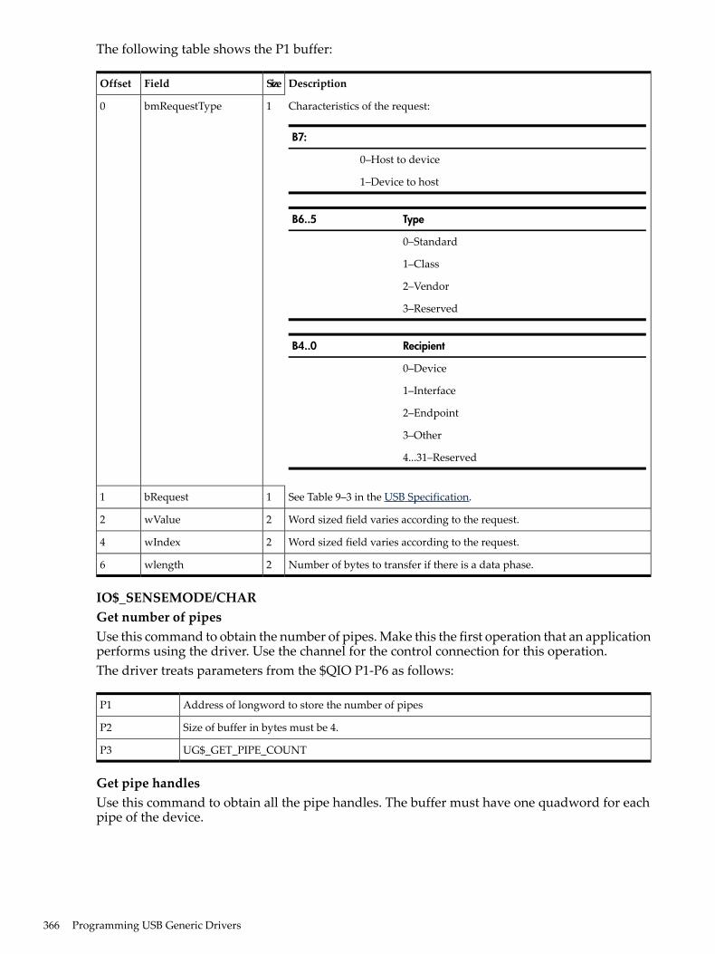
The following table shows the P1 buffer:
DescriptionSizeFieldOffset
Characteristics of the request:
B7:
0–Host to device
1–Device to host
TypeB6..5
0–Standard
1–Class
2–Vendor
3–Reserved
RecipientB4..0
0–Device
1–Interface
2–Endpoint
3–Other
4...31–Reserved
1bmRequestType0
See Table 9–3 in the USB Specification.1bRequest1
Word sized field varies according to the request.2wValue2
Word sized field varies according to the request.2wIndex4
Number of bytes to transfer if there is a data phase.2wlength6
IO$_SENSEMODE/CHARGet number of pipesUse this command to obtain the number of pipes. Make this the first operation that an applicationperforms using the driver. Use the channel for the control connection for this operation.The driver treats parameters from the $QIO P1-P6 as follows:
Address of longword to store the number of pipesP1
Size of buffer in bytes must be 4.P2
UG$_GET_PIPE_COUNTP3
Get pipe handlesUse this command to obtain all the pipe handles. The buffer must have one quadword for eachpipe of the device.
366 Programming USB Generic Drivers

The driver treats parameters from the $QIO P1-P6 as follows:
Address of buffer to hold pipe handlesP1
Size of buffer in bytesP2
UG$_GET_PIPE_HANDLESP3
Get pipe directionUse this command to obtain the direction of a pipe associated with its handle.The driver treats parameters from the $QIO P1-P6 as follows:
Address of buffer to store pipe direction. Legal returns are USB$_XFER_OUT, USB$XFER_IN, andUSB$XFER_SETUP.
P1
Must be 4.P2
UG$_GET_PIPE_TYPEP3
Pipe handleP4
Get pipe typeUse this command to obtain the type of pipe associated with its handle.The driver treats parameters from the $QIO P1-P6 as follows:
Address of buffer to store pipe type. Types are UG$_PIPE_TYPE_CONTROL,UG$_PIPE_TYPE_BULK, UG$_PIPE_TYPE_INTERRUPT, UG$_PIPE_TYPE_ISOCHRONOUS(The last type is currently not supported.).
P1
Must be 4.P2
UG$_GET_PIPE_TYPEP3
Pipe handleP4
Get pipe stateUse this command to obtain the state of the pipe.The driver treats parameters from the $QIO P1-P6 as follows:
Address of buffer to hold the pipe state. Values of the pipe state are UG$_PIPE_STATE_ACTIVE,UG$_PIPE_STATE_STALLED, UG$_PIPE_STATE_IDLE.
P1
Must be 4.P2
UG$_GET_PIPE_STATEP3
Pipe handleP4
Get pipe sizeUse this command to obtain the size of the largest transfer on the pipe. (This is really the largestsize that is sent on the bus in one transfer.) Actual requests can be larger. The driver takes careof splitting the transfer up into appropriately sized bus transfers.The driver treats parameters from the $QIO P1-P6 as follows:
Address of buffer to hold pipe sizeP1
Must be 4.P2
E.3 Supported $QIO Functions 367

UG$_GET_PIPE_SIZEP3
Pipe handleP4
Get pipe descriptorUse this routine is used to obtain the device descriptor from the device.The driver treats parameters from the $QIO P1-P6 as follows:
Address of buffer to receive the device descriptor. The format of the buffer is shown in the table, Format ofthe Device Descriptor.
P1
Size of buffer in bytes.P2
UG$_GET_PIPE_SIZEP3
UG$_GET_DEVICE_DESCRIPTORP4
Table E-1 Format of the Device Descriptor
Descriptor length in bytesug$b_blengthunsigned char
Descriptor type constant 0X01ug$b_bdescriptortypeunsigned char
BCD-encoded specification release numberug$w_bcdusbunsigned short int
Device class codeug$b_bdeviceclassunsigned char
Device sub class codeug$b_bdevicesubclassunsigned char
Device protocolug$b_bdeviceprotocolunsigned char
Maximum packet size for control pipe; 8, 16, 32, 64 are valid.ug$b_bmaxpacketunsigned char
Vendor IDug$w_idvendorunsigned short int
Product IDug$w_idproductunsigned short int
BCD encoded device release number.ug$w_bcddeviceunsigned short int
Index of string descriptor that describes the manufacturer.ug$b_imanufacturerunsigned char
Index of string descriptor that describes the product.ug$b_iproductunsigned char
ndex of string descriptor of device serial number.ug$b_iserailnumberunsigned char
Number of possible device configurations.ug$b_bnumconfigurationsunsigned char
Get interface descriptorUse this command to obtain the interface descriptor from the device.The driver treats parameters from the $QIO P1-P6 as follows:
Address of buffer to receive the interface descriptor. The format of the buffer is shown in the table, Formatof the Interface Descriptor.
P1
Size of buffer in bytes.P2
UUG$_GET_INTERFACE_DESCRIPTORP3
Table E-2 Format of the Interface Descriptor
Descriptor length in bytesug$b_blengthunsigned char
Descriptor type constant 0X04ug$b_bdescriptortypeunsigned char
Zero-based count of this interfaceug$b_binterfacenumberunsigned char
368 Programming USB Generic Drivers
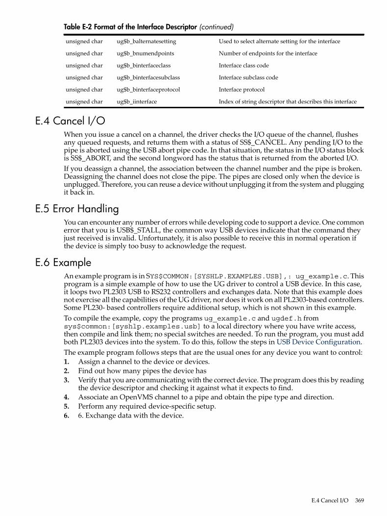
Table E-2 Format of the Interface Descriptor (continued)
Used to select alternate setting for the interfaceug$b_balternatesettingunsigned char
Number of endpoints for the interfaceug$b_bnumendpointsunsigned char
Interface class codeug$b_binterfaceclassunsigned char
Interface subclass codeug$b_binterfacesubclassunsigned char
Interface protocolug$b_binterfaceprotocolunsigned char
Index of string descriptor that describes this interfaceug$b_iinterfaceunsigned char
E.4 Cancel I/OWhen you issue a cancel on a channel, the driver checks the I/O queue of the channel, flushesany queued requests, and returns them with a status of SS$_CANCEL. Any pending I/O to thepipe is aborted using the USB abort pipe code. In that situation, the status in the I/O status blockis SS$_ABORT, and the second longword has the status that is returned from the aborted I/O.If you deassign a channel, the association between the channel number and the pipe is broken.Deassigning the channel does not close the pipe. The pipes are closed only when the device isunplugged. Therefore, you can reuse a device without unplugging it from the system and pluggingit back in.
E.5 Error HandlingYou can encounter any number of errors while developing code to support a device. One commonerror that you is USB$_STALL, the common way USB devices indicate that the command theyjust received is invalid. Unfortunately, it is also possible to receive this in normal operation ifthe device is simply too busy to acknowledge the request.
E.6 ExampleAn example program is in SYS$COMMON:[SYSHLP.EXAMPLES.USB],: ug_example.c. Thisprogram is a simple example of how to use the UG driver to control a USB device. In this case,it loops two PL2303 USB to RS232 controllers and exchanges data. Note that this example doesnot exercise all the capabilities of the UG driver, nor does it work on all PL2303-based controllers.Some PL230- based controllers require additional setup, which is not shown in this example.To compile the example, copy the programs ug_example.c and ugdef.h fromsys$common:[syshlp.examples.usb] to a local directory where you have write access,then compile and link them; no special switches are needed. To run the program, you must addboth PL2303 devices into the system. To do this, follow the steps in USB Device Configuration.The example program follows steps that are the usual ones for any device you want to control:1. Assign a channel to the device or devices.2. Find out how many pipes the device has3. Verify that you are communicating with the correct device. The program does this by reading
the device descriptor and checking it against what it expects to find.4. Associate an OpenVMS channel to a pipe and obtain the pipe type and direction.5. Perform any required device-specific setup.6. 6. Exchange data with the device.
E.4 Cancel I/O 369

E.7 USB Device ConfigurationUSB device configuration is as simple as adding some text lines to SYS$USER_CONFIG.DAT; itis also simple to do wrong.You perform USB configuration with the same files that you use to configure device controllersfor OpenVMS: SYS$CONFIG.DAT and SYS$USER_CONFIG.DAT. Both files are located in theSYS$SYSTEM: directory. As you might expect, user-written drivers add their configurationrecords to SYS$USER_CONFIG.DAT; OpenVMS does not modify the contents – even across O/Supgrades.The contents of the files are evaluated: SYS$USER_CONFIG.DAT is evaluated first, andSYS$CONFIG.DAT second, allowing a user-written configuration record to supersede asystem-supplied record.USB is different from normal OpenVMS device configuration in several respects:• The devices are not classic bus-based controllers, but, rather, devices connected to a peripheral
bus.• You can attach and remove devices at will, even at runtime. which requires USB drivers to
be loaded on the fly as well as made offline on the fly.• Simple vendor/device identification matching, which is performed for other buses, is not
sufficient to determine which driver to load for a USB device.• USB device drivers are part of a larger “stack” of drivers; the controller port driver, the HUB
driver, or the HID driver are involved in aspects of configuration and operation of the device.A USB device driver is a pseudo-driver in the sense that it does not directly talk to the device,but passes messages to other drivers that can talk to the USB bus and send messages to andreceive messages from USB devices.
• The USB protocol was developed to allow device-to-driver matching to be done on multiplelevels, depending on the type of device and the needs of the driver.
• Device discovery is asynchronous on the USB bus, and it is not feasible to poll the bus tofind devices. Instead, devices are configured in response to an event from a HUB deviceindicating that it has a new device to report. HUBs are both external devices that provideadditional slots, and a Root HUB is built onto the controller to which the initial USBconnections are attached.
• You can attach and remove devices at will, even at runtime. which requires USB drivers tobe loaded on the fly as well as made offline on the fly.
The UGDRIVER is the basis of a “generic” driver. It is the functional equivalent of the SCSIGKDRIVER for USB devices; it implements simple logic that takes care of USB housekeepingand allows a user to read and write raw data packets to the USB device.The Basics of Configuration describes how to (configure UGDRIVER to a specific device or aspecific class of devices), and how to make sure that UGDRIVER does not interfere with theconfiguration of other devices and their drivers.The Basics of ConfigurationUSB devices include the device itself and one or more Interfaces. Most devices present a singleinterface. An interface can be serviced by a single driver, or by multiple drivers. A single drivercan also service multiple interfaces. Though this procedure seems complex, for the typical USBdevice, there is only one interface.When a new device is discovered by a HUB, the HUB driver collects information about the deviceand sends a message to the USB Configuration Manager (UCM), which is a background processthat hibernates, waiting to service configuration events. UCM is the code that knows how toperform device-to -driver matching and how to load device drivers. UCM also maintains anon-disk database of device-to-driver mappings that it previously performed and made permanent(persistent). This database allows a device always to obtain the same OpenVMS device nameeach time it is plugged in.Plugging In A New DeviceThe HUB driver collects information about the device and its interfaces, and then requests UCMto attempt to configure and load a device driver for it. The HUB driver does this in the followingmethods:
370 Programming USB Generic Drivers

• First it tries to configure the device as a “DEVICE,” the simplest type of configuration; itignores the interface information. Devices can be identified by vendor_id, product_id,revision, device_class, device_subclass, and device_protocol.
• If a driver is not successfully configured, then the HUB driver asks UCM to try to configurethe device as an “INTERFACE”—for each interface the device presents (which is usuallyonly one). Interfaces are identified by vendor_id, product_id, revision, interface_class,interface_subclass, and interface_protocol. The vendor and product ID codes and revisionvalue are inherited from the device.
NOTE: This discussion excludes Human Interface Devices. These devices involve humaninteraction—such as a mouse, keyboard, joystick, simulator, tablet, or game pad—and are handledby a special HID driver. HID devices are identified by a two-byte value of Usage Page and UsageType; these values are combined into a 16-bit value “TAG,” and device- driver matching isperformed by searching for a matching TAG value. The UG driver can be used to talk to a HIDdevice, but it cannot be loaded using the HID Usage Page/Type values. A second generic HIDdriver is needed for that purpose.
The Generic ListUCM now has the device information it needs to match to a device driver. To do this, it examinesthe Generic list. It has created this list by reading the SYS$USER_CONFIG.DAT file and theSYS$CONFIG.DAT file, searching for records that contain a private section with aUSB_CONFIG_TYPE record.The records in the file are simple; each record starts with a DEVICE keyword and ends with anEND_DEVICE keyword. USB records are pseudo-devices in the sense that they provide noADAPTER type and do not have a conventional device ID. Instead, using the BEGIN_PRIVATEand END_PRIVATE construct, they provide USB-specific information. Within this private dataarea, each line starts with a USB keyword.The following table lists the USB keywords:
DescriptionKeyword
Tells UCM how the driver is to be configured – as a DEVICE, INTERFACE or TAGmethod.
USB_CONFIG_TYPE
Used for specialized drivers that are class drivers for other USB drivers such as theHID driver. You do not need to use it. The values are SINGLE_INSTANCE andMULTIPLE_INSTANCE.
USB_CLASS_DRIVER
Vendor IDVENDOR_ID
Product IDPRODUCT_ID
Revision numberRELEASE_NUMBER
The device class codeDEVICE_CLASS
Device subclassDEVICE_SUB_CLASS
Device protocolDEVICE_PROTOCOL
Starts an interface definition. (There can be multiple interface definitions.)BEGIN_INTERFACE
Interface classINTERFACE_CLASS
Interface subclassINTERFACE_SUB_CLASS
Interface protocolINTERFACE_PROTOCOL
Ends an interface definition.END_INTERFACE
The Usage Page/Type TAG for HID devicesHID_USAGE_DATA
E.7 USB Device Configuration 371

An alternate TAG type used by HID-like drivers for performing TAG lookups; forexample, the EDGEPORT Serial Multiplexer uses this.
USAGE_TAG
Used to enable some extra logging (not available to normal drivers – used by CLASSdrivers)
USB_LOGGING
In addition, the standard DEVICE and DRIVER keywords must be included outside theBEGIN_PRIVATE and END_PRIVATE section, telling UCM the device name and driver nameto use for the device.UCM parses this data into a data structure and creates an in-memory Generic list of all the USBdevices that are in the files. The queue is in the same order as the devices appear in the file, andthe SYS$USER_CONFIG.DAT records come before the SYS$CONFIG.DAT records.The data in this list is used to match against the configuration request that the HUB driver makes.The matching process can be considered complex.Device ConfigurationIn device configuration, the hub driver asks UCM to configure the device by device, not byinterface or tag.
NOTE: In general, drivers do not use device configuration; rather, they use interfaceconfiguration. The most common use of device configuration is to load special device classessuch as hub devices. For a general driver, the only practical use of device configuration is to forcethe loading of a specific device driver, regardless of any other configuration records that mightotherwise match.
The match logic for a device that has not been connected to the system before is not a simplecomparison of all the fields in search of a match. The reason is that a driver (and its configurationrecord) can match a variety of devices; this is a generic driver. Alternatively, you might have avendor-specific driver.The driver class code can be 0-255, and 255 can have special meanings: If the device code is zero,the device present has no device class, no subclass, and no protocol; all of these fields are 0. Ifthe class is 255 (0xFF), the protocol is vendor-specific and must match the vendor ID.A set of tests determines whether a generic record matches the configuration request. The testsare not all equal: A“priority” is assigned to each test. All the generic records are scanned. Arecord that matches is compared against the previous match; if the new match has a greaterpriority, it is used. If no records have matched, a zero is used. This matching means the following:• Higher priority matches win over lower ones.• Duplicate matches of the same priority ignore subsequent matches.In this manner, records are created so that drivers are selected from more specific to less specific.The following tests are in order of priority—from best match to worst match. When only a fieldis included, both the configuration request and the generic list entry field must match. When ageneric field must be 0 (because omitting the field in the device record in the file sets it to zero),the request field is ignored.Match 1:• Vendor ID• Product ID• Release Number• Device Class• Device Subclass• Device ProtocolMatch 2:• Vendor ID• Product ID• Release Number• Device Class
372 Programming USB Generic Drivers
• Device Subclass• Generic Device Protocol must be 0Match 3:• Vendor ID• Product ID• Release Number• Generic Device Protocol must be 0Match 4:• Vendor ID• Product ID• Generic Record Release Number must be 0• Generic Device Protocol must be 0Match 5:• Generic Vendor ID must be 0• Generic Product ID must be 0• Generic Release Number must be 0• Device Class (not 255)• Device Subclass• Device ProtocolMatch 5:• Generic Vendor ID must be 0• Generic Product ID must be 0• Generic Release Number must be 0• Device Class (not 255)• Device SubclassThe matching tests show that an entry that is fully qualified always matches before a more genericone.Note that there is no explicit testing for a Device Class of 0 because the standard requires thatdevices with a class field of 0 have the subclass and protocol set to 0. The preceding tests handleclasses of 0 correctly.All tests in which the device class cannot be 255 require that the generic record contain no vendorID (and, by implication, no product ID and no Release Number). This allows the hub record, forexample, which has no vendor or product IDs, to match against all devices with a class code of9. However, a user record that provides only the vendor and product IDs claims a device witha class code of 9 over the generic hub record.The tests might be tuned to provide a finer granularity, but, in general, the current tests provideall the control a user might need for configuring a device.Interface ConfigurationAn interface configuration means that the hub driver asks UCM to configure the device byinterface—not by device or tag. The match logic for a device interface that has not been connectedto the system before is not simply a comparison of all the fields looking for a match, because youcan have an interface driver (and a configuration record for it) that can match a variety of devices;this is a generic driver. However, you might have a vendor-specific driver.The interface class code can be 0 through 255. The value 255 has a unique meaning: If the classis 255 (0xFF), the interface is vendor-specific and must match the vendor ID.A set of tests determines if a generic record matches the configuration request. The tests are notall equal – a “priority” is assigned to each test, and all the generic records are scanned. A recordthat matches is compared against the previous match (or against zero if no matches are found).If the new match has a greater priority, it is used. This matching means the following:• Higher priority matches win over lower ones.• Duplicate matches of the same priority ignore subsequent matches.
E.7 USB Device Configuration 373

In this manner of matching, records can be created so that drivers are selected from more specificto less specific. The following tests are in order of priority—from best match to worst match.When only one field is given, both the configuration request and the generic list entry field mustmatch. When a generic field must be 0 (because omitting the field in the device record in the filesets it to 0), the request field is ignored.Match 1:• Vendor ID• Product ID• Interface Class• Interface Subclass• Interface ProtocolMatch 2:• Vendor ID• Product ID• Interface Class• Interface Subclass• Generic Interface Protocol must be 0Match 3:• Vendor ID• Interface Class must be 255• Interface Subclass• Interface ProtocolMatch 4:• Vendor ID• Interface Class must be 255• Interface Subclass• Generic Interface Protocol must be 0Match 5:• Generic Vendor ID must be 0• Generic Product ID must not be 255• Interface Subclass• Interface ProtocolMatch 6:• Generic Vendor ID must be 0• Interface Class must not be 255• Interface SubclassJust as in device matching, the order is from strongest match to weakest match, from more specificto less specific, from vendor-specific to generic.
374 Programming USB Generic Drivers
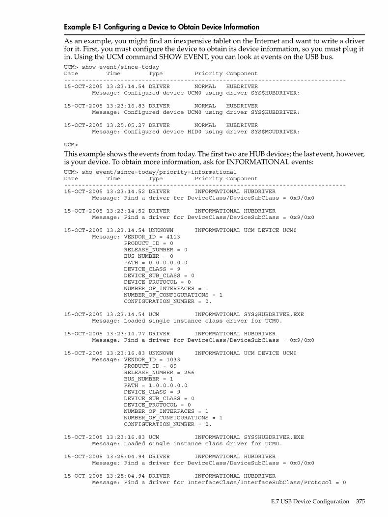
Example E-1 Configuring a Device to Obtain Device Information
As an example, you might find an inexpensive tablet on the Internet and want to write a driverfor it. First, you must configure the device to obtain its device information, so you must plug itin. Using the UCM command SHOW EVENT, you can look at events on the USB bus.UCM> show event/since=todayDate Time Type Priority Component--------------------------------------------------------------------------------15-OCT-2005 13:23:14.54 DRIVER NORMAL HUBDRIVER Message: Configured device UCM0 using driver SYS$HUBDRIVER:
15-OCT-2005 13:23:16.83 DRIVER NORMAL HUBDRIVER Message: Configured device UCM0 using driver SYS$HUBDRIVER:
15-OCT-2005 13:25:05.27 DRIVER NORMAL HUBDRIVER Message: Configured device HID0 using driver SYS$MOUDRIVER:
UCM>
This example shows the events from today. The first two are HUB devices; the last event, however,is your device. To obtain more information, ask for INFORMATIONAL events:UCM> sho event/since=today/priority=informationalDate Time Type Priority Component--------------------------------------------------------------------------------15-OCT-2005 13:23:14.52 DRIVER INFORMATIONAL HUBDRIVER Message: Find a driver for DeviceClass/DeviceSubClass = 0x9/0x0
15-OCT-2005 13:23:14.52 DRIVER INFORMATIONAL HUBDRIVER Message: Find a driver for DeviceClass/DeviceSubClass = 0x9/0x0
15-OCT-2005 13:23:14.54 UNKNOWN INFORMATIONAL UCM DEVICE UCM0 Message: VENDOR_ID = 4113 PRODUCT_ID = 0 RELEASE_NUMBER = 0 BUS_NUMBER = 0 PATH = 0.0.0.0.0.0 DEVICE_CLASS = 9 DEVICE_SUB_CLASS = 0 DEVICE_PROTOCOL = 0 NUMBER_OF_INTERFACES = 1 NUMBER_OF_CONFIGURATIONS = 1 CONFIGURATION_NUMBER = 0.
15-OCT-2005 13:23:14.54 UCM INFORMATIONAL SYS$HUBDRIVER.EXE Message: Loaded single instance class driver for UCM0.
15-OCT-2005 13:23:14.77 DRIVER INFORMATIONAL HUBDRIVER Message: Find a driver for DeviceClass/DeviceSubClass = 0x9/0x0
15-OCT-2005 13:23:16.83 UNKNOWN INFORMATIONAL UCM DEVICE UCM0 Message: VENDOR_ID = 1033 PRODUCT_ID = 89 RELEASE_NUMBER = 256 BUS_NUMBER = 1 PATH = 1.0.0.0.0.0 DEVICE_CLASS = 9 DEVICE_SUB_CLASS = 0 DEVICE_PROTOCOL = 0 NUMBER_OF_INTERFACES = 1 NUMBER_OF_CONFIGURATIONS = 1 CONFIGURATION_NUMBER = 0.
15-OCT-2005 13:23:16.83 UCM INFORMATIONAL SYS$HUBDRIVER.EXE Message: Loaded single instance class driver for UCM0.
15-OCT-2005 13:25:04.94 DRIVER INFORMATIONAL HUBDRIVER Message: Find a driver for DeviceClass/DeviceSubClass = 0x0/0x0
15-OCT-2005 13:25:04.94 DRIVER INFORMATIONAL HUBDRIVER Message: Find a driver for InterfaceClass/InterfaceSubClass/Protocol = 0
E.7 USB Device Configuration 375

x3/0x0/0x0
15-OCT-2005 13:25:04.99 UNKNOWN INFORMATIONAL UCM DEVICE HID0 Message: VENDOR_ID = 2250 PRODUCT_ID = 16 RELEASE_NUMBER = 261 BUS_NUMBER = 1 PATH = 1.2.0.0.0.0 DEVICE_CLASS = 0 DEVICE_SUB_CLASS = 0 DEVICE_PROTOCOL = 0 NUMBER_OF_INTERFACES = 1 CONFIGURATION_VALUE = 1 INTERFACE_NUMBER = 0 INTERFACE_PROTOCOL = 0 INTERFACE_CLASS = 3 INTERFACE_SUB_CLASS = 0 NUMBER_OF_CONFIGURATIONS = 1 MANUFACTURER_STRING = AIPTEK International Inc. PRODUCT_STRING = USB Tablet Series Version 1.05 CONFIGURATION_NUMBER = 0 CURRENT_INTERFACE = 0.
15-OCT-2005 13:25:04.99 UCM INFORMATIONAL SYS$HIDDRIVER.EXE Message: Loaded single instance class driver for HID0.
15-OCT-2005 13:25:05.00 DRIVER INFORMATIONAL HIDDRIVER Message: Find a driver for usage page 0001 usage type 0002
15-OCT-2005 13:25:05.27 UNKNOWN INFORMATIONAL UCM DEVICE MOU Message: BUS_NUMBER = 1 PATH = 1.2.0.0.0.0.HID_USAGE_DATA = 65538.
UCM>
This display provides more information. The last section shows the device, which uses an InterfaceClass of 3, the class that causes the Human Interface Driver (HID) to claim it.To configure your driver (UGDRIVER), assume that you want to handle only this device (becausethe generic Interface driver for this class is HID) and currently no way exists to provideuser-written HID drivers.Edit SYS$USER_CONFIG.DAT to add the following record:device = "CyberTablet 12000"name = UGdriver = sys$ugdriverbegin_privateusb_config_type = interfacevendor_id = 2250product_id = 16begin_interfaceinterface_class = 3interface_sub_class = 0interface_protocol = 0end_interfaceend_privateend_device
This new record indicates that if a device has the vendor code of 2250, and product ID of 16, andInterface Class of 3, and Protocol and Subclass of 0, load the UGDRIVER and call the device UG.All numbers came from the event information. You must include a vendor and product codebecause you do not want other devices, such as a generic mouse or some other vendor’s tablet,to use your driver.You then must reload the database for UCM by using the RELOAD or RESTART command. Thedifference between the two commands is that a RESTART (besides reading in new configurationdata) also removes any in-memory structures that might have been built by earlier device events.
376 Programming USB Generic Drivers

In this case, you create a MOU0 (USB MOUSE) device; MOU0, by default, is never saved as apermanent device (see the description of permanent devices). To reduce the amount of informationin the event file, you must reset it, then you unplug the device and plug it back in as shown inthe following example:$ UCMUniversal Serial Bus Configuration Manager, Version V1.0UCM> restartRestart UCM Server? [N]: yWaiting for UCM Server image to exit....Waiting for UCM Server image to restart....%USB-S-SRVRRESTART, Identification of new UCM Server is 0000021EUCM> set log/newUCM> show eventDate Time Type Priority Component--------------------------------------------------------------------------------15-OCT-2005 13:47:13.58 DECONFIGURED NORMAL HUBDRIVER Message: Deconfiguring device on bus 1 at port 2 bus tier 2 usb address 3
15-OCT-2005 13:47:14.76 UCM NORMAL SYS$UGDRIVER.EXE Message: Tentative device UGA0 proposed... auto-loading driver.
15-OCT-2005 13:47:14.78 UCM NORMAL UGA Message: Auto-perm converting tentative device UGA0 into permanent device.
15-OCT-2005 13:47:14.88 DRIVER NORMAL HUBDRIVER Message: Configured device UGA0 using driver SYS$UGDRIVER:
UCM>
The messages indicate that the device was loaded.If you display INFORMATIONAL data, you see the following additional information:UCM> show event/priority=allDate Time Type Priority Component--------------------------------------------------------------------------------15-OCT-2005 13:47:13.58 DECONFIGURED NORMAL HUBDRIVER Message: Deconfiguring device on bus 1 at port 2 bus tier 2 usb address 3
15-OCT-2005 13:47:14.71 DRIVER INFORMATIONAL HUBDRIVER Message: Find a driver for DeviceClass/DeviceSubClass = 0x0/0x0
15-OCT-2005 13:47:14.71 DRIVER INFORMATIONAL HUBDRIVER Message: Find a driver for InterfaceClass/InterfaceSubClass/Protocol = 0x3/0x0/0x0
15-OCT-2005 13:47:14.76 UNKNOWN INFORMATIONAL UCM DEVICE UGA Message: VENDOR_ID = 2250 PRODUCT_ID = 16 RELEASE_NUMBER = 261 BUS_NUMBER = 1 PATH = 1.2.0.0.0.0 DEVICE_CLASS = 0 DEVICE_SUB_CLASS = 0 DEVICE_PROTOCOL = 0 NUMBER_OF_INTERFACES = 1 CONFIGURATION_VALUE = 1 INTERFACE_NUMBER = 0 INTERFACE_PROTOCOL = 0 INTERFACE_CLASS = 3 INTERFACE_SUB_CLASS = 0 NUMBER_OF_CONFIGURATIONS = 1 MANUFACTURER_STRING = AIPTEK International Inc. PRODUCT_STRING = USB Tablet Series Version 1.05 CONFIGURATION_NUMBER = 0 CURRENT_INTERFACE = 0.
15-OCT-2005 13:47:14.76 UCM NORMAL SYS$UGDRIVER.EXE Message: Tentative device UGA0 proposed... auto-loading driver.
15-OCT-2005 13:47:14.78 UCM NORMAL UGA Message: Auto-perm converting tentative device UGA0 into permanent device.
15-OCT-2005 13:47:14.88 DRIVER NORMAL HUBDRIVER Message: Configured device UGA0 using driver SYS$UGDRIVER:
UCM>
E.7 USB Device Configuration 377

The most significant part of the device configuration is that it does not interfere with other deviceswith the same interface class; for example, the joystick also uses class 3, subclass 0, and protocol0. However, if you plug in a joystick, it correctly uses the HID driver, which uses the genericmatch for Interface Class 3 to load the joystick driver (AGDRIVER), as shown in the followingexample:
378 Programming USB Generic Drivers

UCM> show event/priority=allDate Time Type Priority Component--------------------------------------------------------------------------------15-OCT-2005 13:47:13.58 DECONFIGURED NORMAL HUBDRIVER Message: Deconfiguring device on bus 1 at port 2 bus tier 2 usb address 3
15-OCT-2005 13:47:14.71 DRIVER INFORMATIONAL HUBDRIVER Message: Find a driver for DeviceClass/DeviceSubClass = 0x0/0x0
15-OCT-2005 13:47:14.71 DRIVER INFORMATIONAL HUBDRIVER Message: Find a driver for InterfaceClass/InterfaceSubClass/Protocol = 0x3/0x0/0x0
15-OCT-2005 13:47:14.76 UNKNOWN INFORMATIONAL UCM DEVICE UGA Message: VENDOR_ID = 2250 PRODUCT_ID = 16 RELEASE_NUMBER = 261 BUS_NUMBER = 1 PATH = 1.2.0.0.0.0 DEVICE_CLASS = 0 DEVICE_SUB_CLASS = 0 DEVICE_PROTOCOL = 0 NUMBER_OF_INTERFACES = 1 CONFIGURATION_VALUE = 1 INTERFACE_NUMBER = 0 INTERFACE_PROTOCOL = 0 INTERFACE_CLASS = 3 INTERFACE_SUB_CLASS = 0 NUMBER_OF_CONFIGURATIONS = 1 MANUFACTURER_STRING = AIPTEK International Inc. PRODUCT_STRING = USB Tablet Series Version 1.05 CONFIGURATION_NUMBER = 0 CURRENT_INTERFACE = 0.
15-OCT-2005 13:47:14.76 UCM NORMAL SYS$UGDRIVER.EXE Message: Tentative device UGA0 proposed... auto-loading driver.
15-OCT-2005 13:47:14.78 UCM NORMAL UGA Message: Auto-perm converting tentative device UGA0 into permanent device.
15-OCT-2005 13:47:14.88 DRIVER NORMAL HUBDRIVER Message: Configured device UGA0 using driver SYS$UGDRIVER:
15-OCT-2005 14:16:46.55 DECONFIGURED NORMAL HUBDRIVER Message: Deconfiguring device on bus 1 at port 2 bus tier 2 usb address 3
15-OCT-2005 14:16:49.46 DRIVER INFORMATIONAL HUBDRIVER Message: Find a driver for DeviceClass/DeviceSubClass = 0x0/0x0
15-OCT-2005 14:16:49.46 DRIVER INFORMATIONAL HUBDRIVER Message: Find a driver for InterfaceClass/InterfaceSubClass/Protocol = 0x3/0x0/0x0
15-OCT-2005 14:16:49.49 UNKNOWN INFORMATIONAL UCM DEVICE HID0 Message: VENDOR_ID = 1699 PRODUCT_ID = 13630 RELEASE_NUMBER = 256 BUS_NUMBER = 1 PATH = 1.2.0.0.0.0 DEVICE_CLASS = 0 DEVICE_SUB_CLASS = 0 DEVICE_PROTOCOL = 0 NUMBER_OF_INTERFACES = 1 CONFIGURATION_VALUE = 1 INTERFACE_NUMBER = 0 INTERFACE_PROTOCOL = 0 INTERFACE_CLASS = 3 INTERFACE_SUB_CLASS = 0 NUMBER_OF_CONFIGURATIONS = 1 MANUFACTURER_STRING = Saitek PRODUCT_STRING = Cyborg evo Wireless CONFIGURATION_NUMBER = 0 CURRENT_INTERFACE = 0.
15-OCT-2005 14:16:49.49 UCM INFORMATIONAL SYS$HIDDRIVER.EXE Message: Loaded single instance class driver for HID0.
15-OCT-2005 14:16:49.50 DRIVER INFORMATIONAL HIDDRIVER Message: Find a driver for usage page 0001 usage type 0005
15-OCT-2005 14:16:49.63 UNKNOWN INFORMATIONAL UCM DEVICE AGA Message: BUS_NUMBER = 1 PATH = 1.2.0.0.0.0.HID_USAGE_DATA = 65541.
E.7 USB Device Configuration 379
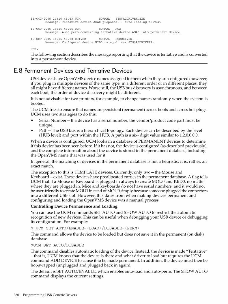
15-OCT-2005 14:16:49.63 UCM NORMAL SYS$AGDRIVER.EXE Message: Tentative device AGA0 proposed... auto-loading driver.
15-OCT-2005 14:16:49.65 UCM NORMAL AGA Message: Auto-perm converting tentative device AGA0 into permanent device.
15-OCT-2005 14:16:49.78 DRIVER NORMAL HUBDRIVER Message: Configured device HID0 using driver SYS$AGDRIVERR:
UCM>
The following section describes the message reporting that the device is tentative and is convertedinto a permanent device.
E.8 Permanent Devices and Tentative DevicesUSB devices have OpenVMS device names assigned to them when they are configured; however,if you plug in multiple devices of the same type, in a different order or in different places, theyall might have different names. Worse still, the USB bus discovery is asynchronous, and betweeneach boot, the order of device discovery might be different.It is not advisable for two printers, for example, to change names randomly when the system isbooted.The UCM tries to ensure that names are persistent (permanent) across boots and across hot-plugs.UCM uses two strategies to do this:• Serial Number—If a device has a serial number, the vendor/product code part must be
unique.• Path—The USB bus is a hierarchical topology. Each device can be described by the level
(HUB level) and port within the HUB. A path is a six- digit value similar to 1.2.0.0.0.0.When a device is configured, UCM looks in a database of PERMANENT devices to determineif this device has been seen before. If it has not, the device is configured (as described previously),and the complete information about the device is stored in the permanent database, includingthe OpenVMS name that was used for it.In general, the matching of devices in the permanent database is not a heuristic; it is, rather, anexact match.The exception to this is TEMPLATE devices. Currently, only two—the Mouse andKeyboard—exist. These devices have preallocated entries in the permanent database. A flag tellsUCM that if a Mouse or Keyboard is plugged in always to create MOU0 and KBD0, no matterwhere they are plugged in. Mice and keyboards do not have serial numbers, and it would notbe user-friendly to create MOU1 instead of MOU0 simply because someone plugged the connectorsinto a different USB slot. However, this dates from when making devices permanent andconfiguring and loading the OpenVMS device was a manual process.Controlling Device Permanence and LoadingYou can use the UCM commands SET AUTO and SHOW AUTO to restrict the automaticrecognition of new devices. This can be useful when debugging your USB device or debuggingits configuration. For example:$ UCM SET AUTO/ENABLE=(LOAD)/DISABLE=(PERM)
This command allows the device to be loaded but does not save it in the permanent (on disk)database.$UCM SET AUTO/DISABLE
This command disables automatic loading of the device. Instead, the device is made “Tentative”– that is, UCM knows that the device is there and what driver to load but requires the UCMcommand ADD DEVICE to cause it to be made permanent. In addition, the device must then behot-swapped (unplugged and plugged back in again).The default is SET AUTO/ENABLE, which enables auto-load and auto-perm. The SHOW AUTOcommand displays the current settings.
380 Programming USB Generic Drivers

In addition, you can set EXCLUDE and INCLUDE lists. For more information, see the UCMsection of the HP OpenVMS System Management Utilities Manual.
E.8 Permanent Devices and Tentative Devices 381

382

Index
Symbols$QIO, 1853C589 Ethernet device, 27164-bit virtual addressing
device driver support, 17802 Extended (IEEE 802.x LLC/SNAP) frame format, 266
AACP (ancillary control process), 21ACP functions, 21, 51
attributes, 34, 36disk quotas, 53IO$_ACCESS, 26, 29, 33, 44IO$_ACPCONTROL, 26IO$_CREATE, 29, 30, 33, 42IO$_DEACCESS, 32, 33, 45IO$_DELETE, 26, 47IO$_MODIFY, 26, 30, 32, 33, 46IO$_MOUNT, 51magnetic tape positioning, 52miscellaneous disk, 52quota file transfer block, 54
ACP subfunctions, 26access, 29directory lookup, 26extend, 30, 55movefile, 46read/write attributes, 33truncate, 32
ACP-QIO interface, 21(see also See also FIBs)access file function, 44access subfunction, 29ACP control function, 51ANSI standard, 21, 52arguments, 22
disk quota, 54attribute control block, 33attributes, 34, 36attributes statistics block, 41BLISS-32 programming, 21create file function, 42
disk, 43magnetic tape, 44
deaccess file function, 45delete file function, 47description, 21directory entries, 44file characteristics, 37function codes, 329function modifiers, 22
IO$M_ACCESS, 29, 42, 44IO$M_CREATE, 42, 43, 44IO$M_DELETE, 42, 43, 47IO$M_DMOUNT, 51, 52
I/O operations, 21I/O status block, 55MACRO programming, 21movefile subfunction, 48record attributes area, 39
values, 39serious exception (EOT), 42, 45, 52status returns, 329XQP (extended QIO processor), 21
ALTMODE key, 142ANSI escape sequence, 350Applications
connecting to LAT ports, 163Arguments
device- or function-dependent, 22list, 329
ASCII character set, 343(see also See DEC Multinational character set)
ASTs (asynchronous system traps)quota, 60, 83, 106, 159
Asynchronous SCSI data transfer modeenabling, 237, 242
ATM (asynchronous transfer mode)ELAN frames, 263
ATM ELAN frames, 263ATM network
LAN emulation, 280Attention AST, 185
LAN drivers, 300mailbox, 112terminal, 159
AUCBs (audio control blocks)definition, 69
Audio$QIO interface to disk class driver, 68error handling in applications, 71extensions to SCSI disk class driver, 67storing with data on CD-ROM, 72
Audio applicationsprogramming, 73
Audio control blocks, 69(see also See AUCBs)
Autoconfigurationof SCSI device, 239
BBaud rate
of terminal, 157Booting, 282BOT (beginning-of-tape), 88
(see also See BOT markers and Magnetic tapes)Broadcast and unknown server (BUS), 280Broadcast messages, 139, 142, 143, 163Broadcom 5700 Gigabit Ethernet devices, 274Buffered I/O
quota, 60, 83, 106
383

CCarriage control, 155Character sets, 343
(see also See also DEC Multinational character set)terminal lowercase, 142, 343
Charactersterminator set for, 149
Classical IP, 281CONNECT command, 139Console terminals, 127Control characters
list, 343terminal, 128, 130, 133
Control key sequences, 131Create file function, 42
directory entry creation, 44CSMA/CD
definition, 250CTDRIVER driver, 134, 154Ctrl/x key sequence, 127
(see also See Terminals, control characters)
DData
storing with audio information on CD-ROM, 72Data checks
disk, 57, 63, 64magnetic tape, 86, 87
Data transfer modeas controlled by the generic SCSI class driver, 237, 242asynchronous, 237, 242synchronous, 237, 242
Deaccess file function, 45DEC Multinational character set, 343DEFZA FDDI device, 276DEGPA Gigabit Ethernet Devices, 274DEGPA Gigabit Ethernet NIC, 274Delete file function, 47Delete key, 129DEMFA FDDI device, 276Device characteristics
disk, 60LAN drivers, 283magnetic tape, 81mailbox, 106pseudoterminal, 218terminal, 141
Device driversdisks, 57LAT port, 127magnetic tape, 81mailbox, 103pseudoterminal, 217SCSI, 59SCSI disk class, 67shadow set virtual unit, 229terminal, 127
DevicesSCSI support, 229
supported, 229Dialup lines, 136Digital private escape sequence, 350DIOLM process limit, 60Direct I/O
count process limit, 60, 83Directory entry
creation, 44Directory lookup subfunction, 26DISCONNECT command, 139Disconnect features
enabling, 242Disk class drivers
$QIO interface to audio functions, 68audio extensions, 67
Disk drivescompatibility for volume shadowing, 230
Disk quotas, 53, 54, 60Disks, 57
(see also I/O functions\;See also ACP-QIO interface)ACP operation
control function, 52creating file, 43deaccessing file, 46
available function, 66data check, 57, 63, 64device characteristics, 60driver, 57, 67
SCSI, 59error recovery, 58features, 57file attributes, 57function codes, 60, 330function modifiers
IO$M_DATACHECK, 57, 63, 64IO$M_DELDATA, 65IO$M_ERASE, 62, 65IO$M_INHRETRY, 59, 64
I/O functions, 60, 63arguments, 61, 63IO$_ACPCONTROL, 52
I/O status block, 73offset recovery, 58pack acknowledge function, 66programming example, 73quotas, 53, 54, 60read function, 63search function, 65seek operations, 66sense mode function, 65set density function, 65status returns, 330supported devices, 57SYS$GETDVI returns, 60TU58 magnetic tape
data checks, 58read function, 64search function, 65write check function, 67
384 Index

write function, 64unload function, 66write check function, 66write function, 64
DISMOUNT command, 52Drivers
disks, 57LAT port, 127magnetic tape, 81mailbox, 103pseudoterminal, 217SCSI, 59SCSI disk class, 67shadow set virtual unit, 229terminal, 127
DSA (Digital Storage Architecture), 57(see also disks)disks, 57
DSA disks, 57(see also See also Disks)
DSE (data security erase)magnetic tape, 94
Duplex mode, 127(see also See also Half-duplex mode)terminal, 133
EELAN configuring, 282Enable attention AST function
LAN drivers, 300End-of-file, 87
(see also See EOF)End-of-tape markers, 81
(see also See EOT markers)End-of-volume, 90
(see also See EOV)EOF (end-of-file)
status of magnetic tape, 87write mailbox message, 111
EOT markersstatus
magnetic tape, 87, 88, 90EOV (end-of-volume)
detection on magnetic tape, 90Error recovery
disk, 58shadow set virtual unit driver, 231
Escape sequencesANSI, 350Digital private, 350terminal, 131, 142
Ethernetdefinition, 249
Ethernet (Ethernet Version 2, DIX) frame format, 263Ethernet LAN devices, 269Event notification
pseudoterminal, 221Extend subfunction, 30
FFandle, 319Fast I/O
function codes, 336system services, 317
Fast Path, 322function codes, 336
Fast Path performance enhancement, 322FDDI
definition, 249FIBs (file information blocks), 21, 23
(see also See also ACP functions)access control, 29contents, 26descriptor, 22, 23directory lookup, 27disk quota, 53, 54extend control, 31IO$_ACCESS, 45IO$_ACPCONTROL, 51, 54IO$_CREATE, 42IO$_DEACCESS, 46IO$_DELETE, 48IO$_MODIFY, 47truncate control, 32
File characteristicsACP-QIO attributes, 37
File system ACP, 21Form feeds
terminal, 142Full-duplex mode, 133Function codes, 329
(see also See also I/O functions)IO$_ACCESS, 44IO$_ACPCONTROL, 51, 84IO$_AVAILABLE, 66, 94IO$_CREATE, 42IO$_DEACCESS, 45IO$_DELETE, 47IO$_DSE, 94IO$_FORMAT, 65IO$_MODIFY, 46IO$_PACKACK, 66IO$_READLBLK, 63, 86, 107, 147, 285IO$_READPBLK, 63, 86, 107, 285IO$_READPROMPT, 147IO$_READVBLK, 63, 86, 107, 147, 285IO$_REWIND, 88IO$_REWINDOFF, 90IO$_SEARCH, 65IO$_SEEK, 63, 66IO$_SENSECHAR, 65, 186IO$_SENSEMODE, 65, 90, 186, 304IO$_SETCHAR, 91, 156, 289IO$_SETMODE, 91, 156, 289IO$_SKIPFILE, 88IO$_SKIPRECORD, 89IO$_UNLOAD, 66, 90IO$_WRITECHECK, 66
385

IO$_WRITELBLK, 64, 87, 110, 154, 287IO$_WRITEOF, 90IO$_WRITEPBLK, 64, 87, 110, 154, 287IO$_WRITEVBLK, 64, 87, 110, 154, 287list of, 329
Function modifiersfor LAN driver, 287IO$M_ACCESS, 42, 44, 84IO$M_ATTNAST, 300IO$M_BRDCST, 163, 188IO$M_BREAKTHRU, 134, 154IO$M_CANCTRLO, 129, 154IO$M_CREATE, 42, 44, 84IO$M_CTRL, 299, 304IO$M_CTRLCAST, 159IO$M_CTRLYAST, 130, 159IO$M_CVTLOW, 148IO$M_DATACHECK, 57, 63, 64, 86, 87IO$M_DELDATA, 65IO$M_DELETE, 42, 47IO$M_DMOUNT, 51IO$M_DSABLMBX, 148IO$M_ENABLMBX, 154IO$M_ERASE, 62, 65, 87IO$M_ESCAPE, 131, 148IO$M_EXTEND, 148, 149IO$M_HANGUP, 159IO$M_INCLUDE, 159, 162IO$M_INHRETRY, 64IO$M_MAINT, 160, 161IO$M_MOVEFILE, 46IO$M_NOECHO, 134, 145, 148IO$M_NOFILTR, 148IO$M_NOFORMAT, 134, 154IO$M_NORSWAIT, 110, 111IO$M_NOW, 107, 110, 111, 287IO$M_NOWAIT, 88, 90IO$M_OUTBAND, 161IO$M_PURGE, 148IO$M_RD_MODEM, 187IO$M_READATTN, 112IO$M_READERCHECK, 110, 111, 115IO$M_REFRESH, 154IO$M_RESPONSE, 289IO$M_REVERSE, 86IO$M_SET_MODEM, 160IO$M_SETPROT, 115IO$M_SHUTDOWN, 299IO$M_STREAM, 107IO$M_TIMED, 148IO$M_TRMNOECHO, 148IO$M_TT_ABORT, 162IO$M_TYPEAHDCNT, 187IO$M_UNLOOP, 161IO$M_WRITERCHECK, 107, 115list of, 329
GGeneric SCSI class driver, 233
$QIO system service format for, 240, 243assigning a channel to, 240flow of, 235, 236I/O status block returned by, 240loading, 239obtaining device information from, 244programming example, 244security considerations, 237
Generic SCSI descriptorformat of, 241, 243
HHalf-duplex mode, 127, 133, 142
(see also See also Duplex mode)Hangup function modifier
terminaldisconnecting a, 159interaction with, 139, 145
Hardwaresupported, 229
Hardware interruptspreferred CPU, 322
II/O buffers
pseudoterminal, 219I/O drivers
disk, 57magnetic tapes, 81mailbox, 103
I/O functionsACP-QIO interface, 21disk, 21, 60for LAN driver, 284list of, 329magnetic tape, 21, 82mailbox, 106terminal, 147
I/O write operationspreventing data loss, 58unsuccessful completion, 58
IEEEdefinition, 249
INITIALIZE command, 94Intel 82540 Gigabit Ethernet devices, 276Intel 82559 Fast Ethernet devices, 273IO$_M_SET_MAC functional modifier, 300IO$_SETMODE
IO$M_UPDATE_MAP, 302IO$M_ALLOWFAST modifier, 88IO$M_LT_QUE_CHG_NOTIF
LAT $QIO Function Modifier, 185IO$M_ROUTE functional modifier, 303IO$M_SENSE_MAC
Used with IO$_SENSEMODE, 306IO$M_SENSE_MAC functional modifier, 306IO$M_SHOW_MAP
Used with IO$_SENSEMODE, 308IO$M_SHOW_MAP functional modifier, 308
386 Index

IO$M_SHOW_ROUTEUsed with IO$_SENSEMODE, 308
IO$M_SHOW_ROUTE functional modifier, 308IO$M_UPDATE_MAP functional modifier, 302IOSBs (I/O status blocks)
ACP-QIO interface, 55disk, 73LAN drivers, 310LAT port driver, 189magnetic tape, 95mailbox, 115returned by generic SCSI class driver, 240terminal, 189
Itemlist read operations, 149
JJumbo frames
definition, 250
KKeyboard control character, 128, 130, 133
LLAN
application APIs, 256frame formats, 260I/O architecture, 254software modules, 255terminology, 249
LAN device drivers, 249LAN drivers
addressesdestination, 285, 288hardware, 305loopback assistance, 258multicast, 258, 285physical, 258, 285, 295, 305port, 295source, 285Token Ring, 259
AST access mode, 300AST service routine address, 300attention AST, 300buffer
receive, 285characteristics
device, 283, 304extended, 290, 298, 305
CRC generation, 292device characteristics, 283, 304echo mode (DEUNA only), 293error summary bits, 284Ethernet packet padding, 267exclusive mode on Alpha systems, 267extended characteristics, 290, 304function codes, 284, 335function modifiers, 287, 289, 299, 304I/O functions, 285, 287, 289, 304I/O status block, 310
IEEE 802 packet formatClass I service packet format, 264extended packet format, 266read function, 285SAP use and restrictions, 265support for, 253write function, 287
IEEE 802 programming example, 311message size, 283, 286, 287, 288modify characteristics, 290packet format
Class I service, 264extended 802, 266set mode parameters, 299SNAP SAP value, 266
paddingmessage size, 283, 287transmit messages, 295
parameter ID, 290packet format, 299
parameter validation, 299port
start, 290privilege, 285programming example, 311programming notes, 310promiscuous mode, 310
rules for, 311protocol type, 263, 285, 288
access mode, 291cross-company, 263
protocol type on Alpha systemssharing, 267
protocol type sharing on Alpha systems, 267read function, 285sense mode function, 304Service Access Point (SAP), 265set controller mode
extended characteristics, 290P2 buffer, 290parameter ID, 290
set controller mode on Alpha systemsprotocol type sharing, 267
set mode function, 289shared default mode on Alpha systems, 267shared with destination mode on Alpha systems, 267shutdown controller mode, 299shutdown port, 299status returns, 335SYS$GETDVI routine, 283unit and line status, 283write function, 287
LAN emulationATM network, 280topology, 280
LAN emulation client (LEC), 280LAN emulation configuration server (LECS), 280LAN emulation data frame format, 263LAN emulation server (LES), 280
387

LANCE Ethernet devices, 270LANCP commands, 282LAT $QIO, 185LAT port driver (LTDRIVER), 127LAT SENSEMODE $QIO Function, 171LAT SETMODE $QIO Function, 165LEMAC Ethernet devices, 270Line terminator
terminal, 133LTDRIVER (LAT port driver), 127
MMagnetic tapes, 81
(see also I/O functions\;See ACP-QIO interface)function codes, 331status returns, 332
Mailboxes, 103(see also See also Terminals)creating, 103deleting, 105device characteristics, 106disable terminal, 142driver, 103function codes, 106, 332function modifiers
IO$M_NORSWAIT, 110, 111IO$M_NOW, 107, 110, 111, 113IO$M_READATTN, 112IO$M_READERCHECK, 110, 111, 115IO$M_SETPROT, 115IO$M_STREAM, 107IO$M_WRITERCHECK, 107, 115
get mailbox information function, 115I/O functions
IO$_READLBLK, 107IO$_READPBLK, 107IO$_READVBLK, 107IO$_WRITELBLK, 110IO$_WRITEOF, 111IO$_WRITEPBLK, 110IO$_WRITEVBLK, 110
I/O status block, 115list of operations, 103message format, 105
terminal, 140message size, 103permanent, 103, 105programming examples, 117protection, 103, 105, 115read attention AST function, 112read function, 107set attention AST function, 112set protection function, 115status returns, 333SYS$GETDVI returns, 106temporary, 103, 105terminal/mailbox interaction, 139volume protection, 115wait for writer/reader function, 114
write attention AST function, 112write end-of-file message function, 111write function, 110
MAXBUF system parameter, 147, 149, 154(see also See also System parameters)
Message format, 140(see also See Mailboxes)
Modify file function, 46MOUNT command, 94Mount function, 51Movefile subfunction
calling, 48description, 48
Multinational character set, 343(see also See DEC Multinational character set)
OOSI model, 250Out-of-band AST, 136, 161
PPacket padding, 267Parity flag, 158PASTHRU mode, 133, 134, 145, 147PDQ FDDI devices, 277Permanent mailboxes, 105
(see also See Mailboxes)PID sharing, 267Pseudoterminals
canceling request, 218creating, 217deleting, 218device characteristics, 218driver, 217event notification, 221features, 218flow control, 220I/O buffers, 219programming example, 222reading data, 220using write with echo, 220writing data, 220
QQIO API, 256Quota file
transfer block, 54Quotas
AST, 60, 83, 106, 112, 159buffered I/O, 60, 83, 106BYTELIM, 30direct I/O, 60, 83disk, 53, 54mailbox buffer, 103, 105, 106
RRadix-50 encoding, 38RADs support, 327
(see also See Resource Affinity Domains support)
388 Index

Read attention AST function, 112Read/write attributes
ACP-QIO interface, 33Read/write attributes subfunction, 33Record attributes value, 39Resource Affinity Domains (RADs) support, 327Return key, 130Rewind offline function, 90RTPAD component of SET HOST, 134
SSCSI (Small Computer Systems Interface)
$QIO interface to disk class driver, 68disk class driver, 67disks
class driver, 59error recovery, 58, 59
handling errors in audio applications, 71SCSI class driver, 234SCSI class/port architecture, 233SCSI command
disabling retry, 238enabling retry, 242padding, when required, 243setting disconnect timeout for, 243setting DMA timeout for, 239, 243setting phase change timeout for, 239, 243
SCSI disconnect featureenabling, 238
SCSI port driver, 234Sense tape mode function, 90Set attention AST, 112
(see also See Attention AST)SET HOST facility, 134Set modes
magnetic tape, 91mailbox, 112Set Mac qualifier, 300terminal, 156
SET TERMINAL command, 128, 140, 146Setting characteristics
magnetic tape, 91terminal, 156
SGEC/TGEC Ethernet devices, 270Shadow set virtual unit driver, 229
functions, 230hardware configurations, 229
Shared Memory Ethernet device, 276SHDRIVER functions, 229Shelving
determining if file is shelvable, 37determining if file is shelved, 37
Skip file function, 88SS$_ABORT return, 161, 183, 330, 332, 333, 335SS$_ACCONFLICT return, 329SS$_ACCVIO return, 116, 333, 335SS$_ACPVAFUL return, 329SS$_BADATTRIB return, 329SS$_BADCHKSUM return, 329
SS$_BADESCAPE return, 131SS$_BADFILEHDR return, 329SS$_BADFILENAME return, 329SS$_BADFILEVER return, 329SS$_BADIRECTORY return, 329SS$_BADPARAM return, 268, 290, 299, 329, 335SS$_BADQFILE return, 329SS$_BLOCKCNTERR return, 329SS$_BUFFEROVF return, 107, 305, 333, 335SS$_CANCEL return, 330, 332, 333SS$_COMMHARD return, 335SS$_CONTROLC return, 162SS$_CREATED return, 329SS$_CTRLERR return, 330, 332, 335SS$_DATACHECK return, 330, 332, 335SS$_DATAOVERUN return, 132, 286, 330, 332, 335SS$_DEVACTIVE, 185SS$_DEVACTIVE return, 183, 335SS$_DEVALLOC return, 335SS$_DEVICEFULL return, 329SS$_DEVINACT return, 335SS$_DEVOFFLINE return, 332, 335SS$_DEVREQERR, 185SS$_DEVREQERR return, 335SS$_DIRFULL return, 329SS$_DIRNOTEMPTY return, 329SS$_DISCONNECT return, 335SS$_DRVERR return, 330, 332SS$_DUPDSKQUOTA return, 329SS$_DUPFILENAME return, 329SS$_DUPUNIT return, 335SS$_ENDOFFILE return, 89, 109, 111, 287, 329
LAN driver status return, 335magnetic tape status return, 332mailbox status return, 333
SS$_ENDOFTAPE return, 332SS$_ENDOFVOLUME return, 89, 332SS$_EXBYTLM return, 329SS$_EXDISKQUOTA return, 329SS$_EXQUOTA return, 116, 333, 335SS$_FCPREADERR return, 329SS$_FCPREWNDERR return, 329SS$_FCPSPACERR return, 329SS$_FCPWRITERR return, 329SS$_FILELOCKED return, 329SS$_FILENUMCHK return, 329SS$_FILEPURGED return, 329SS$_FILESEQCHK return, 329SS$_FILESTRUCT return, 329SS$_FILNOTEXP return, 329SS$_FORCEDERR return, 330SS$_FORMAT return, 330, 332SS$_HANGUP return, 136SS$_HEADERFULL return, 329SS$_IBCERROR return, 329SS$_IDXFILEFULL return, 329SS$_ILLCNTRFUNC return, 329SS$_ILLIOFUNC return, 116, 183, 330, 332, 333SS$_INFMAPREG return, 336
389

SS$_INFMEM return, 116, 333, 335SS$_IVADDR return, 330SS$_IVBUFLEN return, 289, 330, 336SS$_MBFULL return, 104, 110, 116, 333SS$_MBTOOSML return, 116, 333SS$_MEDOFL return, 330, 332, 336SS$_NODISKQUOTA return, 329SS$_NOMOREFILES return, 329SS$_NONEXDRV return, 330, 332SS$_NOPRIV return, 115, 116, 329, 333, 336SS$_NOQFILE return, 329SS$_NOREADER return, 333SS$_NORMAL return, 116, 183, 330, 332, 336SS$_NOSUCHFILE return, 329SS$_NOTAPEOP return, 329SS$_NOTLABELMT return, 329SS$_NOTPRINTED return, 329SS$_NOTVOLSET return, 329SS$_NOWRITER return, 333SS$_OPINCOMPL return, 330, 332, 336SS$_OVRDSKQUOTA return, 329SS$_PARITY return, 330, 332SS$_PARTESCAPE return, 131, 150SS$_QFACTIVE return, 329SS$_QFNOTACT return, 329SS$_RCT return, 330SS$_RDDELDATA return, 330SS$_SERIOUSEXCP return, 329, 332SS$_SUPERSEDE return, 329SS$_TAPEPOSLOST return, 329SS$_TIMEOUT return, 148, 183, 330, 332, 336SS$_TOOMANYVER return, 329SS$_TOOMUCHDATA return, 336SS$_UNSAFE return, 330, 332SS$_VOLINV return, 330, 332SS$_WASECC return, 330SS$_WRITLCK return, 329, 330, 332SS$_WRONGACP return, 329Synchronous SCSI data transfer mode
enabling, 237, 242SYS$ASSIGN routine, 103, 139, 184SYS$CREMBX system service, 103SYS$DASSGN routine, 105SYS$DELMBX system service, 105SYS$DISMOU system service, 52SYS$GETDVI routine, 81
disk, 60LAN drivers, 283mailbox, 106SCSI generic class driver, 244terminal, 141
SYS$QIO routinesformat for request to SCSI generic class driver, 240
SYS$QIO system serviceinterface to audio functions, 68
SYSGEN (System Generation utility), 239(see also See System Generation utility)
Systemconsole terminal, 127
System Generation utility (SYSGEN)configuring SCSI devices, 239
TTabs
Ctrl/I, 130terminal mechanical, 142terminal tab stops, 154
Tape marks, 87, 88, 89Tapes
ACP control function, 51, 84ACP create file operation, 44available function, 94BOT marker, 88, 89byte count
read, 87write, 88
data check, 86, 87data security erase function, 94density, 93device characteristics for, 81driver, 81end-of-volume detection, 90EOF status, 87EOT marker, 88
status, 87, 88, 90extended characteristics, 82function codes, 82, 83function modifiers
IO$M_DATACHECK, 86, 87IO$M_ERASE, 87IO$M_NOWAIT, 88, 90IO$M_REVERSE, 86
I/O functions, 82arguments, 85IO$_ACCESS, 84IO$_ACPCONTROL, 52, 84IO$_AVAILABLE, 94IO$_CREATE, 84IO$_DEACCESS, 84IO$_DSE, 84, 94IO$_FLUSH, 84IO$_MODIFY, 84, 94IO$_PACKACK, 94IO$_READLBLK, 86IO$_READPBLK, 86IO$_READVBLK, 86IO$_REWIND, 88IO$_REWINDOFF, 90IO$_SENSEMODE, 90IO$_SETCHAR, 91IO$_SETMODE, 91IO$_SKIPFILE, 88IO$_SKIPRECORD, 89IO$_UNLOAD, 90IO$_WRITELBLK, 87IO$_WRITEOF, 90IO$_WRITEPBLK, 87IO$_WRITEVBLK, 87
390 Index

I/O status block, 95modify function, 94pack acknowledge function, 94parity, 93positioning, 52programming example, 95quotas, 83read function, 86read reverse function, 86, 87rewind function, 88rewind offline function, 90sense mode function, 90set characteristics function, 91set mode function, 91, 92skip file function, 88skip record function, 89status returns, 83supported devices, 81SYS$GETDVI returns, 81tape controllers, 81tape mark, 87, 88, 89TMSCP and SCSI magnetic tapes, 81unload function, 90write end-of-file function, 90write function, 87
Temporary mailboxes, 105Terminal characteristics, 141, 143, 146Terminals, 127, 136
(see also line editing\;See also Terminals, item codes)(see also out-of-band\;See also Out-of-band AST)ANSI CRT terminal, 143autobaud detection, 140, 143baud rates, 140, 143, 157bell (Ctrl/G), 132broadcast messages, 139, 142, 143, 163carriage control, 155command line editing, 127, 153command recall (Ctrl/B), 128, 130control and data signals, 137control characters, 128, 130, 133, 147
numeric values, 343control key sequences, 131cursor movement, 127, 130, 143delete character, 127delete line (Ctrl/U), 129, 147device characteristics, 141, 143, 146
categories, 146changing, 158extended, 146
dialupcharacteristic, 143lines, 136, 144, 159support, 135
Digital CRT terminal, 144discard output (Ctrl/O), 129, 147, 154driver, 127duplex modes, 133, 135enable Ctrl/C AST, 159enable Ctrl/Y AST, 159
escape sequences, 131, 189ANSI, 350Digital private, 350overflow size (item code), 150
extended characteristics, 146fallback conversion, 134, 145, 159features, 127form feed, 142, 154frame size, 158function codes, 147, 333function modifiers
IO$M_BRDCST, 163, 188IO$M_BREAKTHRU, 134, 154IO$M_CANCTRLO, 129, 154IO$M_CTRLCAST, 159IO$M_CTRLYAST, 130, 136, 159IO$M_CVTLOW, 148IO$M_DSABLMBX, 148IO$M_ENABLMBX, 154IO$M_ESCAPE, 131, 148IO$M_EXTEND, 148, 149IO$M_HANGUP, 159IO$M_INCLUDE, 141, 159, 162IO$M_LOOP, 161IO$M_LT_CONNECT, 165IO$M_LT_DISCON, 165IO$M_LT_SENSEMODE, 165IO$M_LT_SETMODE, 165IO$M_MAINT, 160, 161IO$M_NOECHO, 133, 134, 145, 148IO$M_NOFILTR, 148IO$M_NOFORMAT, 134, 154, 161IO$M_OUTBAND, 161IO$M_PURGE, 148IO$M_RD_MODEM, 187IO$M_REFRESH, 154IO$M_SET_MODEM, 160IO$M_TIMED, 148IO$M_TRMNOECHO, 148IO$M_TT_ABORT, 141, 162IO$M_TYPEAHDCNT, 187IO$M_UNLOOP, 161
hangup, 136, 139, 144, 145, 159, 186I/O functions
CTDRIVER, 154IO$_READLBLK, 147IO$_READPROMPT, 147IO$_READVBLK, 147IO$_SENSECHAR, 186IO$_SENSEMODE, 186IO$_SETCHAR, 156IO$_SETMODE, 156IO$_TTY_PORT, 165IO$_WRITELBLK, 154IO$_WRITEPBLK, 154IO$_WRITEVBLK, 154
I/O status block, 189initiate login, 133input processing, 127
391

insert/overstrike (Ctrl/A), 127, 130interrupt (Ctrl/Y), 130item codes, 153itemlist read, 149
item codes, 153item descriptor, 150
LAT port driver, 163application services creation, 184I/O functions, 164
LAT rejection codes, 190line editing, 127, 144line feed, 154line terminators, 133mailbox, 139, 154
message format, 140message types, 139
modemcharacteristic, 142control signals, 137data signals, 137protocol, 136sense signals, 187signal control, 136
modem signal control, 136no type-ahead, 142out-of-band
characters, 141output
CTDRIVER, 134RTPAD, 134SET HOST, 134
output formatting, 134, 146output processing, 133page length and width, 157, 187parity flag, 158PASTHRU mode, 133, 134, 145, 147process preservation, 139programming examples, 191protocol, 136read function, 147, 153read verify, 131, 153receive speed, 157redisplay data (Ctrl/R), 130, 147ReGIS graphics, 145restart data (Ctrl/Q), 130sense characteristics function, 186sense mode function, 186set characteristics function, 156
arguments, 157set mode function, 156
arguments, 157SET TERMINAL DCL command, 128, 140, 146SIXEL graphics, 145special operating modes, 133status (Ctrl/T), 130status returns, 335stop data (Ctrl/S), 130SYS$GETDVI returns, 141system password, 145
tabCtrl/I, 130mechanical, 142stops, 154
terminator mask, 149time (Ctrl/T), 130transmit speed, 157TTY_DIALTYPE system parameter, 136, 137, 138type-ahead, 132, 139, 142, 187
alternate buffer, 143unsolicited data, 139virtual support, 139write breakthrough function, 154write function, 154, 156XON/XOFF control, 145
Terminator character bit mask, 149ThinWire, 253Timeout periods
for SCSI device, 239, 243Token Ring
Address mappings, 259definition, 249function address mapping, 259LAN devices, 277
Truncate subfunction, 32Tulip Ethernet and Fast Ethernet devices, 272
UUnload function
disk, 66magnetic tape, 90
USBgeneric drive, 363
VVCI API, 257
WWrite attention AST function, 112Write breakthrough function, 154Write end-of-file function
magnetic tape, 90message, 111
Write protectionhardware, 230
XXQP (extended QIO processor), 21
392 Index