hp pro x2 612 g2 retail solutions tablet keyboard hp pro ... · pdf filehp pro x2 612 g2...
TRANSCRIPT
HP Pro x2 612 G2 TabletHP Pro x2 612 G2 Tablet with Collaboration KeyboardHP Pro x2 612 G2 Retail Solutions Tablet
Maintenance and Service Guide

© Copyright 2017 HP Development Company, L.P.
AMD is a trademark of Advanced Micro Devices, Inc. Bluetooth is a trademark owned by its proprietor and used by HP Inc. under license. Intel, Core, and Pentium are trademarks of Intel Corporation in the U.S. and other countries. Windows is either a registered trademark or trademark of Microsoft Corporation in the United States and/or other countries.
Product notice
This guide describes features that are common to most models. Some features may not be available on your computer.
Not all features are available in all editions or versions of Windows. Systems may require upgraded and/or separately purchased hardware, drivers, software or BIOS update to take full advantage of Windows functionality. Windows 10 is automatically updated, which is always enabled. ISP fees may apply and additional requirements may apply over time for updates. Go to http://www.microsoft.com for details.
The information contained herein is subject to change without notice. The only warranties for HP products and services are set forth in the express warranty statements accompanying such products and services. Nothing herein should be construed as constituting an additional warranty. HP shall not be liable for technical or editorial errors or omissions contained herein.
First Edition: January 2017
Document Part Number: 913265-001

Table of contents
1 Product description ....................................................................................................................................... 1
2 External component identification .................................................................................................................. 5
Locating hardware ................................................................................................................................................. 5
Locating software .................................................................................................................................................. 5
Right ....................................................................................................................................................................... 5
Left ......................................................................................................................................................................... 6
Front ....................................................................................................................................................................... 8
Top .......................................................................................................................................................................... 9
Bottom ................................................................................................................................................................. 10
Rear ...................................................................................................................................................................... 11
Keyboard components (select products only) .................................................................................................... 13
Connecting an optional keyboard ..................................................................................................... 13
Removing the keyboard .................................................................................................................... 14
TouchPad ........................................................................................................................................... 14
Lights ................................................................................................................................................. 15
Special keys ....................................................................................................................................... 17
Action keys ........................................................................................................................................ 18
Hot keys ............................................................................................................................................................... 19
Labels ................................................................................................................................................................... 19
3 Illustrated parts catalog .............................................................................................................................. 21
Computer major components .............................................................................................................................. 21
Miscellaneous parts ............................................................................................................................................. 23
4 Removal and replacement procedures preliminary requirements .................................................................... 25
Tools required ...................................................................................................................................................... 25
Service considerations ......................................................................................................................................... 25
Plastic parts ....................................................................................................................................... 25
Cables and connectors ...................................................................................................................... 26
Drive handling ................................................................................................................................... 26
Grounding guidelines ........................................................................................................................................... 27
Electrostatic discharge damage ........................................................................................................ 27
Packaging and transporting guidelines .......................................................................... 28
Workstation guidelines ................................................................................................... 28
Equipment guidelines ..................................................................................................... 29
iii

5 Removal and replacement procedures for Customer Self-Repair parts ............................................................. 30
Component replacement procedures .................................................................................................................. 30
Keyboard (select products only) ....................................................................................................... 31
Micro SIM card tray ............................................................................................................................ 32
MicroSD memory card tray ................................................................................................................ 33
Rear cover .......................................................................................................................................... 34
Disconnecting the battery ................................................................................................................. 35
Kickstand ........................................................................................................................................... 36
SSD ..................................................................................................................................................... 38
6 Removal and replacement procedures for Authorized Service Provider parts ................................................... 40
Component replacement procedures .................................................................................................................. 40
WWAN or GPS module ....................................................................................................................... 41
Rear webcam and flash ..................................................................................................................... 43
Display panel ..................................................................................................................................... 45
Battery ............................................................................................................................................... 49
Hall effects sensor board .................................................................................................................. 51
NFC module ....................................................................................................................................... 53
System board .................................................................................................................................... 55
POGO connector ................................................................................................................................ 58
Microphone board ............................................................................................................................. 58
Front webcam .................................................................................................................................... 59
Fingerprint reader board ................................................................................................................... 59
Smart card reader board and bracket ............................................................................................... 61
Volume button ................................................................................................................................... 64
Power button ..................................................................................................................................... 66
Speakers ............................................................................................................................................ 68
Antennas ............................................................................................................................................ 70
Middle frame ..................................................................................................................................... 71
7 Backup and recovery .................................................................................................................................... 72
Creating recovery media and backups ................................................................................................................ 72
Creating HP Recovery media (select products only) ......................................................................... 72
Using Windows tools ........................................................................................................................................... 73
Restore and recovery ........................................................................................................................................... 74
Recovering using HP Recovery Manager ........................................................................................... 74
What you need to know before you get started ............................................................. 74
Using the HP Recovery partition (select products only) ................................................. 75
Using HP Recovery media to recover .............................................................................. 75
Changing the boot order ................................................................................................. 75
iv
Removing the HP Recovery partition (select products only) ......................................... 76
8 Computer Setup (BIOS), TPM, and HP Sure Start ............................................................................................. 77
Using Computer Setup ......................................................................................................................................... 77
Starting Computer Setup .................................................................................................................. 77
Using a USB keyboard or USB mouse to start Computer Setup (BIOS) .......................... 77
Navigating and selecting in Computer Setup ................................................................................... 78
Restoring factory settings in Computer Setup ................................................................................. 78
Updating the BIOS ............................................................................................................................. 79
Determining the BIOS version ......................................................................................... 79
Downloading a BIOS update ........................................................................................... 79
Changing the boot order using the f9 prompt .................................................................................. 80
TPM BIOS settings (select products only) ........................................................................................................... 80
Using HP Sure Start (select products only) ......................................................................................................... 81
9 Using HP PC Hardware Diagnostics (UEFI) ....................................................................................................... 82
Downloading HP PC Hardware Diagnostics (UEFI) to a USB device .................................................................... 82
10 Specifications ............................................................................................................................................ 84
Computer specifications ...................................................................................................................................... 84
Display specifications .......................................................................................................................................... 85
11 Power cord set requirements ...................................................................................................................... 86
Requirements for all countries ............................................................................................................................ 86
Requirements for specific countries and regions ................................................................................................ 87
12 Statement of memory volatility .................................................................................................................. 89
Nonvolatile memory usage ................................................................................................................................. 91
Questions and answers ....................................................................................................................................... 93
Using HP Sure Start (select models only) ............................................................................................................ 94
13 Recycling .................................................................................................................................................. 96
Index ............................................................................................................................................................. 97
v

vi
1 Product description
Category Description
Product Name HP Pro x2 612 G2 Tablet
HP Pro x2 612 G2 Tablet with Collaboration Keyboard
HP Pro x2 612 G2 Retail Solutions Tablet
Processors 7th generation Intel® Pentium® Processor
Intel Pentium 4410Y, (2 M cache), 1.5 GHz, Dual, Thermal Design Power (TDP) 6 W, configurable TDP (cTDP) 4.5 W, not available with Intel Active Management Technology (iAMT)
7th generation Intel Core™ M Processor
Intel Core M3-7Y30 (4 M cache, turbo up to 2.6 GHz), 1.0 GHz, Dual, TDP 4.5 W, cTDP 3.75 W, not available with iAMT
7th generation Intel Core i5 Processor (no support for HP Pro x2 612 G2 Retail Solutions Tablet)
Intel Core i5-7Y54 (4 M cache, turbo up to 3.2 GHz), 1.20 GHz, Dual, TDP 4.5 W, cTDP 3.5 W, not available with iAMT
Intel Core i5-7Y57 (4 M cache, turbo up to 3.3 GHz), 1.20 GHz, Dual, TDP 4.5 W, cTDP 3.5 W
7th generation Intel Core i7 Processor (no support for HP Pro x2 612 G2 Retail Solutions Tablet)
Intel Core i7-7Y75 (4 M cache, turbo up to 3.6 GHz), 1.30 GHz, Dual, TDP 4.5 W, cTDP 3.5 W
Chipset Intel Core 7th generation Premium PCH, integrated with CPU
Graphics Intel UMA graphics
Intel HD Graphics 615
Panel Touch panel
12.0” (30.48 cm) 3:2 (LED backlight – Ultra-Slim) Wide Ultra eXtended Graphics Array (WUXGA+ Bright View (BV) Ultra Wide View Angle (UWVA) 60% 340 nits eDP Ultraslim 2.4 mm Panel Self Refresh (PSR) (1920x1280)
Corning Gorilla 4 Glass, GF2-MM, Direct Bonded
Memory LPDDR3 1866 fine-pitch ball grid array (FBGA) package with 253 balls
Supports dual channel memory, which is included in base units
Supports up to 8 GB
Supports the following configurations:
● 4096 MB (16 Gb 128 Mx32x4, quantity of 2)
● 8192 MB (32 Gb 256 Mx32x4, quantity of 2) (no support for HP Pro x2 612 G2 Retail Solutions Tablet)
Memory is soldered on the system board.
Primary storage Supports M.2 2280 Solid-State Drive (SSD)
128 GB SATA-3
256 GB PCIe Gen3x4 NVMe SS Triple Level Cell (TLC) (no support for HP Pro x2 612 G2 Retail Solutions Tablet)
256 GB SATA-3 SS TLC (OPAL2) (no support for HP Pro x2 612 G2 Retail Solutions Tablet)
360 GB Intel PCIe Gen3x4 SS TLC (no support for HP Pro x2 612 G2 Retail Solutions Tablet)
1

Category Description
512 GB PCIe Gen3x4 NVMe SS TLC (no support for HP Pro x2 612 G2 Retail Solutions Tablet)
512 GB SATA-3 SS TLC (Federal Information Processing Standard)(FIPS), for Cloud-integrated Storage (CIS) only (no support for HP Pro x2 612 G2 Retail Solutions Tablet)
Webcam and microphone
Audio controls
Dual array microphone
Front facing webcam, 5 MP with LED indicator
Back webcam, 8 MP with flash LED
Audio Two stereo speakers
Ethernet No direct Ethernet support - Ethernet via accessories
Supports HBMA (via UEFI PXE boot and Windows OS)
Wireless WLAN
Supports the following WLANs:
● Intel Dual band wireless-AC 8265 802.11AC 2x2 Wi-Fi + Bluetooth® 4.2 combo adaptor (non-vPro), not available with iAMT
● Intel Dual band wireless-AC 8265 802.11AC 2x2 Wi-Fi + Bluetooth 4.2 combo adaptor (vPro), available with iAMT (no support for HP Pro x2 612 G2 Retail Solutions Tablet)
WLAN options on system board, 2 antennas
Support for S3/S4 wake on WLAN (Intel Only)
Support for Wi-Fi SAR in BIOS (Intel Only)
Compatible with Miracast-certified devices
Support for HP Sure Connect
Bluetooth
Bluetooth 4.2, which is only supported via combo card
Supports Bluetooth disabled
GPS
u-blox GPS EVA-M8M M.2/USB WW, not available with WWAN
Supports no GPS option
No support for HP Pro x2 612 G2 Retail Solutions Tablet
NFC (Near Field Communication)
Integrated NFC NXP NPC100 I2C NCI 10 mm x 25 mm module (No Felicity Card (FeliCa) S and M class support)
Supports no NFC option
WWAN
Supports the following WWANs:
● Fibocom HP hs3210 WW HSPA+ without GPS
● Huawei HP It4132, LTE/HSPA+ 4G with GPS M.2
● Foxconn HP It4120 LTE/EVDO/HSPA+ with GPS M.2
SIM module: user-accessible on side (3FF/micro SIM), installed in the factory when a service provider is configured
2 Chapter 1 Product description

Category Description
2 WWAN Antennas
Not available if separate GPS module is selected
Supports non–WWAN option
No support for after-market WWAN
External media cards MicroSD media reader slot
Supports SD/SDHC/SDXC
Uses card tray
Not accessible when HP Retail Case 12 is installed
Sensors Combo chip with the following sensors:
● Accelerometer
● Magnetometer
● Gyro
Ambient Light Sensor (ALS)
Proximity (SAR for WWAN)
Dual Accelerometers in the keyboard only
Ports Audio-out (headphone)/Audio-in (microphone) combo jack
1 USB 3.0 port on the right side
1 USB Type-C power connector and charging port on the right side
Docking station HP Elite USB-C Docking Station
Keyboard/pointing devices
Optional travel keyboard, with backlight and clickpad
Clickpad requirements support the following actions:
● 2-way scroll
● Single and Double Taps enabled as default
● Gestures enabled by default - 2 Finger Scrolling, 2 Finger Zoom (Pinch), 3 Finger tap (Cortana), 4 Finger tap (Action Center)
No support for HP Pro x2 612 G2 Retail Solutions Tablet
Power requirements Batteries:
4-cell Long Life Polymer 41.58 Whr (2700 mAhr)
AC adapters:
1.8 M length power cord supporting the following adapters:
● HP 45 W USB Type-C AC adapter
● HP 65 W USB Type-C AC adapter
Power cord:
1.0 M length power cord with duckhead, for use in select areas
Duckhead, for use in select areas
Security TPM 1.2/2.0
Integrated smart card reader (Active)
3

Category Description
Pad fingerprint reader (optional)
Drive encryption pre-boot (password, fingerprint, select smart cards)
Power-on authentication (password, fingerprint)
Security lock slot
Operating system Preinstalled:
Windows 10 Pro 64
Windows 10 Pro 64 StF MSNA (no support for HP Pro x2 612 G2 Retail Solutions Tablet):
● Windows 10 Pro 64 Shape the Future program for education (StF) Microsoft National Academic Offering (MSNA), only available with Pentium or M3 processors + 4 GB + 128 GB SSD
● Windows 10 Pro 64 StF MSNA EM, only available with Pentium or M3 processors + 4 GB + 128 GB SSD
● Windows 10 Pro 64 StF MSNA High-end, only available with 8 GB RAM
● Windows 10 Pro 64 StF MSNA Standard, only available with 4 GB RAM
● Windows 10 Pro 64 StF MSNA Strategic, only available with Pentium or M3 processors + 4 GB + 128 GB SSD
● Win 10 Home 64 StF MSNA for Higher Education, only available with Pentium or M3 processors + 4 GB + 128 GB SSD
Windows 10 Home 64 (no support for HP Pro x2 612 G2 Retail Solutions Tablet):
● Windows 10 Home 64, only available with 4 GB RAM
● Windows 10 Home 64 Chinese Market CPPP, only available for Asia, People’s Republic of China country locations
● Windows 10 Home Single Language, only available with 4 GB RAM
● Windows 10 Home High End 64, only available with 8 GB RAM
● Windows 10 Home High End 64 Single Language, only available with 8 GB RAM
● Win 10 Home 64 StF MSNA for Higher Education Strategic, only available with Pentium or M3 processors + 4 GB + 128 GB SSD
Windows 10 Internet of Things (IoT) Enterprise for Retail (only available for HP Pro x2 612 G2 Retail Solutions Tablet)
Web-only Support (no support for HP Pro x2 612 G2 Retail Solutions Tablet):
● Windows 10 Enterprise 64
Serviceability End user replaceable parts:
AC adapter
Keyboard (no support for HP Pro x2 612 G2 Retail Solutions Tablet)
Kickstand
Rear cover
SSD
4 Chapter 1 Product description
2 External component identification
Locating hardwareTo find out what hardware is installed on your computer:
▲ Type device manager in the taskbar search box, and then select the Device Manager app.
A list displays all the devices installed on your computer.
For information about system hardware components and the system BIOS version number, press fn+esc (select products only).
Locating softwareTo find out what software is installed on your computer:
▲ Select the Start button.
‒ or –
Right-click the Start button, and then select Programs and Features.
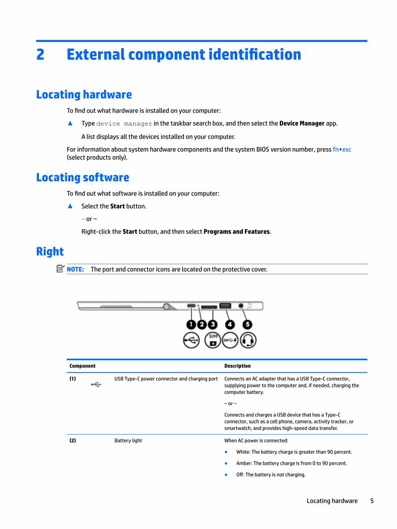
RightNOTE: The port and connector icons are located on the protective cover.
Component Description
(1) USB Type-C power connector and charging port Connects an AC adapter that has a USB Type-C connector, supplying power to the computer and, if needed, charging the computer battery.
– or –
Connects and charges a USB device that has a Type-C connector, such as a cell phone, camera, activity tracker, or smartwatch, and provides high-speed data transfer.
(2) Battery light When AC power is connected:
● White: The battery charge is greater than 90 percent.
● Amber: The battery charge is from 0 to 90 percent.
● Off: The battery is not charging.
Locating hardware 5

Component Description
When AC power is disconnected (battery not charging):
● Blinking amber: The battery has reached a low battery level. When the battery has reached a critical battery level, the battery light begins blinking rapidly.
● Off: The battery is not charging.
(3) Micro SIM card slot (select products only) Supports a wireless subscriber identity module (SIM) card.
(4) USB 3.x charging port When the computer is on, connects and charges a USB device, such as a cell phone, camera, activity tracker, or smartwatch, and provides high-speed data transfer.
(5) Audio-out (headphone)/Audio-in (microphone) combo jack
Connects optional powered stereo speakers, headphones, earbuds, a headset, or a television audio cable. Also connects an optional headset microphone. This jack does not support optional standalone microphones.
WARNING! To reduce the risk of personal injury, adjust the volume before putting on headphones, earbuds, or a headset. For additional safety information, refer to the Regulatory, Safety, and Environmental Notices.
To access this document:
▲ Select the Start button, select HP Help and Support, and then select HP Documentation.
‒ or –
▲ Select the Start button, select HP, and then select HP Documentation.
NOTE: When a device is connected to the jack, the computer speakers are disabled.
LeftNOTE: The port and connector icons are located on the protective cover.
Component Description
(1) Power button ● When the computer is off, press the button to turn on the computer.
● When the computer is on, press the button briefly to initiate Sleep.
● When the computer is in the Sleep state, press the button briefly to exit Sleep.
6 Chapter 2 External component identification

Component Description
● When the computer is in Hibernation, press the button briefly to exit Hibernation.
CAUTION: Pressing and holding down the power button results in the loss of unsaved information.
If the computer has stopped responding and shutdown procedures are ineffective, press and hold the power button for at least 5 seconds to turn off the computer.
To learn more about your power settings, see your power options.
▲ Type power options in the taskbar search box, and then select Power Options.
‒ or –
Right-click the Power meter icon , and then select
Power Options.
(2) Volume button Increases or decreases speaker volume incrementally while you hold down the button.
(3) MicroSD memory card reader Reads optional memory cards that store, manage, share, or access information.
(4) Security cable slot Attaches an optional security cable to the computer.
NOTE: The security cable is designed to act as a deterrent, but it may not prevent the computer from being mishandled or stolen.
(5) Pen lanyard slots Allow you to connect the optional pen using the pen lanyard.
Left 7
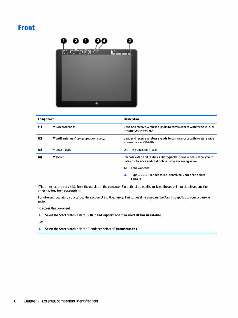
Front
Component Description
(1) WLAN antennas* Send and receive wireless signals to communicate with wireless local area networks (WLANs).
(2) WWAN antennas* (select products only) Send and receive wireless signals to communicate with wireless wide area networks (WWANs).
(3) Webcam light On: The webcam is in use.
(4) Webcam Records video and captures photographs. Some models allow you to video conference and chat online using streaming video.
To use the webcam:
▲ Type camera in the taskbar search box, and then select Camera.
*The antennas are not visible from the outside of the computer. For optimal transmission, keep the areas immediately around the antennas free from obstructions.
For wireless regulatory notices, see the section of the Regulatory, Safety, and Environmental Notices that applies to your country or region.
To access this document:
▲ Select the Start button, select HP Help and Support, and then select HP Documentation.
‒ or –
▲ Select the Start button, select HP, and then select HP Documentation.
8 Chapter 2 External component identification
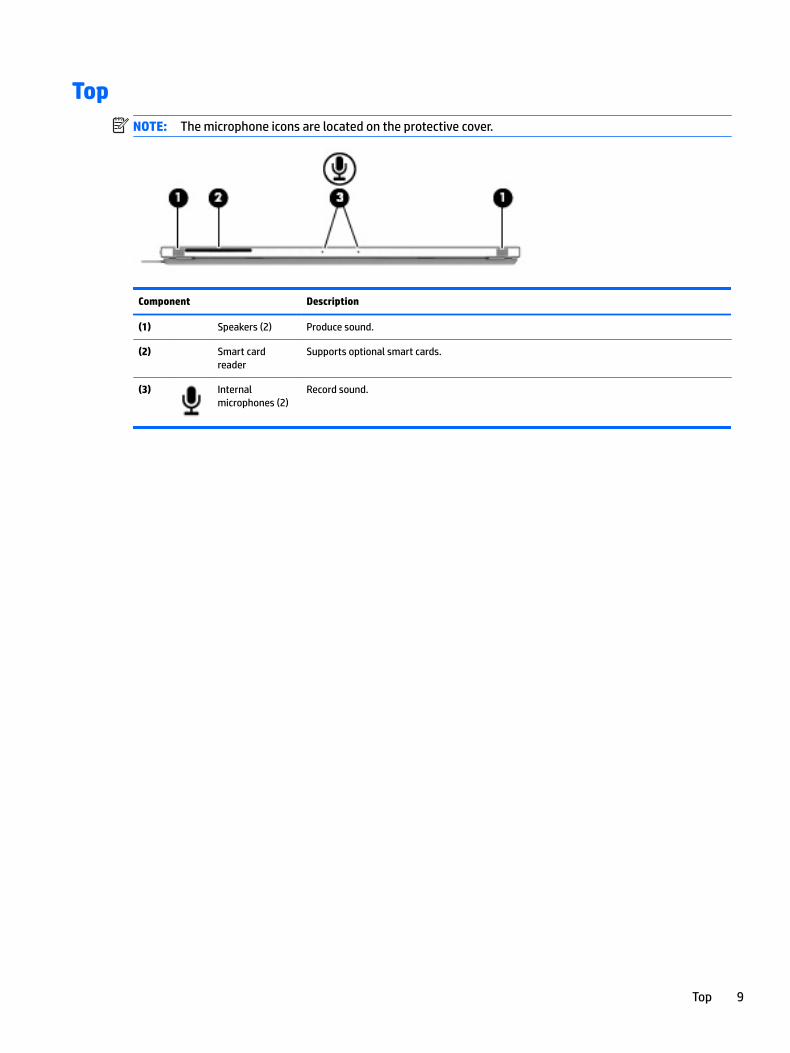
TopNOTE: The microphone icons are located on the protective cover.
Component Description
(1) Speakers (2) Produce sound.
(2) Smart card reader
Supports optional smart cards.
(3) Internal microphones (2)
Record sound.
Top 9
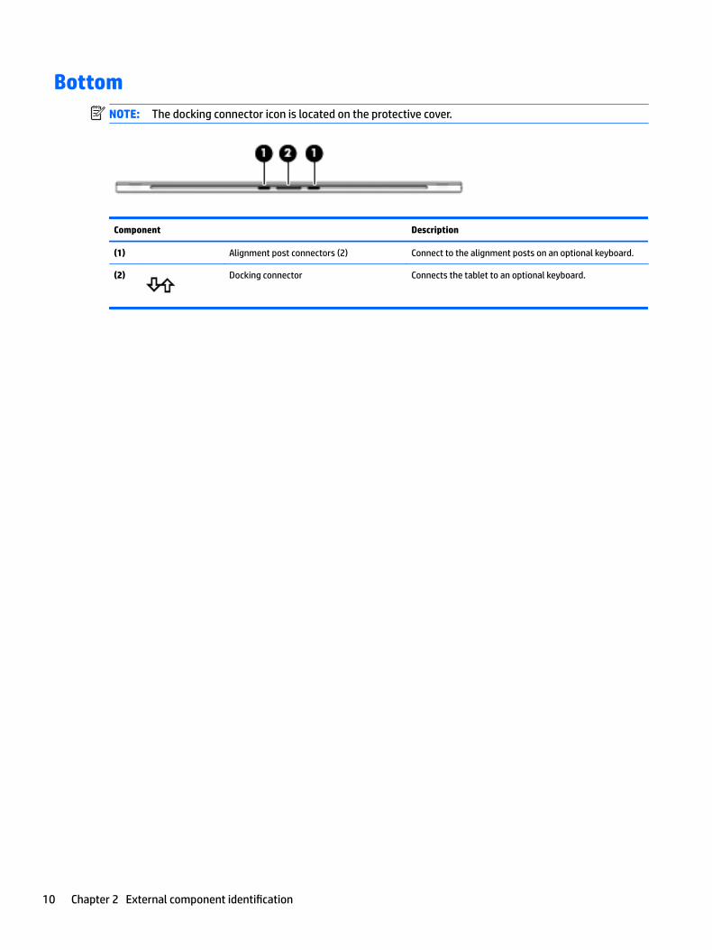
BottomNOTE: The docking connector icon is located on the protective cover.
Component Description
(1) Alignment post connectors (2) Connect to the alignment posts on an optional keyboard.
(2) Docking connector Connects the tablet to an optional keyboard.
10 Chapter 2 External component identification
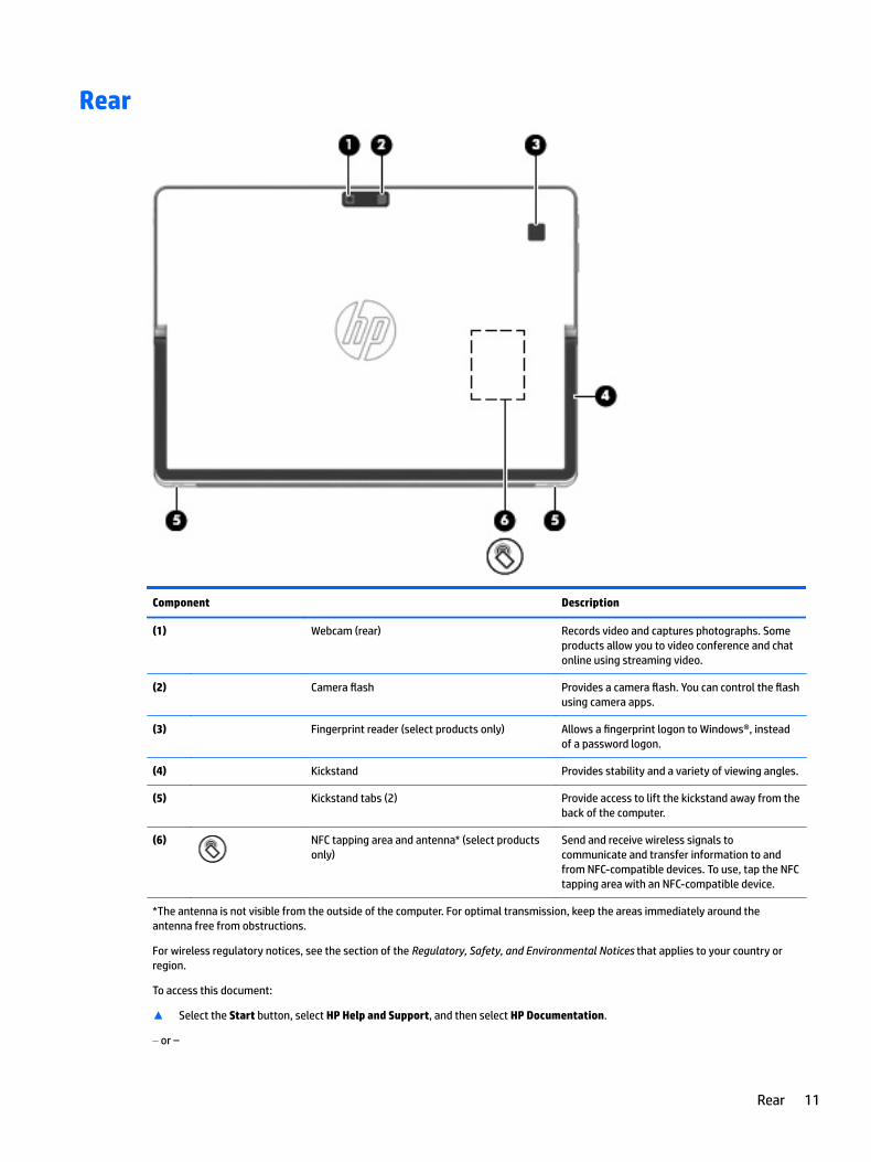
Rear
Component Description
(1) Webcam (rear) Records video and captures photographs. Some products allow you to video conference and chat online using streaming video.
(2) Camera flash Provides a camera flash. You can control the flash using camera apps.
(3) Fingerprint reader (select products only) Allows a fingerprint logon to Windows®, instead of a password logon.
(4) Kickstand Provides stability and a variety of viewing angles.
(5) Kickstand tabs (2) Provide access to lift the kickstand away from the back of the computer.
(6) NFC tapping area and antenna* (select products only)
Send and receive wireless signals to communicate and transfer information to and from NFC-compatible devices. To use, tap the NFC tapping area with an NFC-compatible device.
*The antenna is not visible from the outside of the computer. For optimal transmission, keep the areas immediately around the antenna free from obstructions.
For wireless regulatory notices, see the section of the Regulatory, Safety, and Environmental Notices that applies to your country or region.
To access this document:
▲ Select the Start button, select HP Help and Support, and then select HP Documentation.
‒ or –
Rear 11

Component Description
▲ Select the Start button, select HP, and then select HP Documentation.
12 Chapter 2 External component identification
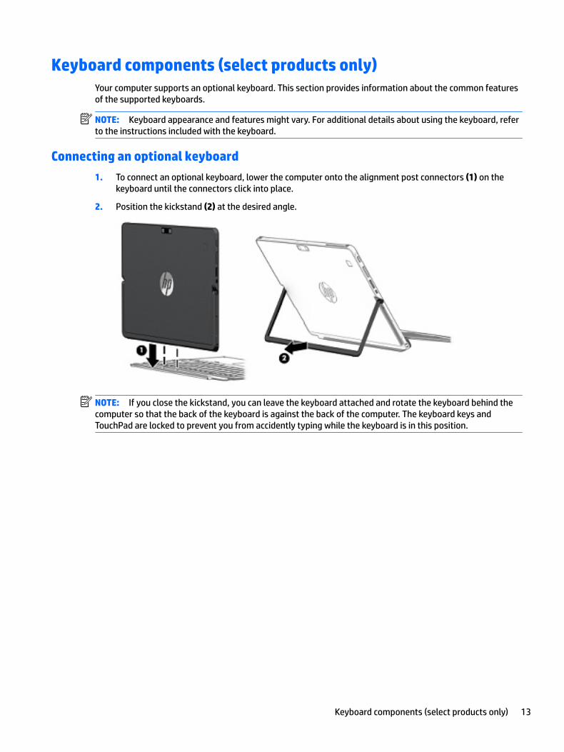
Keyboard components (select products only)Your computer supports an optional keyboard. This section provides information about the common features of the supported keyboards.
NOTE: Keyboard appearance and features might vary. For additional details about using the keyboard, refer to the instructions included with the keyboard.
Connecting an optional keyboard
1. To connect an optional keyboard, lower the computer onto the alignment post connectors (1) on the keyboard until the connectors click into place.
2. Position the kickstand (2) at the desired angle.
NOTE: If you close the kickstand, you can leave the keyboard attached and rotate the keyboard behind the computer so that the back of the keyboard is against the back of the computer. The keyboard keys and TouchPad are locked to prevent you from accidently typing while the keyboard is in this position.
Keyboard components (select products only) 13

Removing the keyboard
To remove the keyboard, pull the keyboard away from the computer.
TouchPad
Component Description
(1) TouchPad zone Reads your finger gestures to move the pointer or activate items on the screen.
(2) Left TouchPad button Functions like the left button on an external mouse.
(3) Right TouchPad button Functions like the right button on an external mouse.
14 Chapter 2 External component identification

Lights
Component Description
(1) Caps lock light On: Caps lock is on, which switches the key input to all capital letters.
(2) Mute light ● On: Computer sound is off.
● Off: Computer sound is on.
(3) Microphone mute light ● On: Microphone sound is off.
● Off: Microphone sound is on.
(4) Num lk light On: Num lock is on.
(5) Wireless light On: An integrated wireless device, such as a wireless local area network (WLAN) device and/or a Bluetooth® device, is on.
NOTE: On some models, the wireless light is amber when all wireless devices are off.
(6) Sharing screen light On: Sharing is on.
NOTE: This feature requires Skype® for Business or Lync® 2013 running on Microsoft Exchange or Office 365® servers.
(7) Call answer light ● Blinking: The phone app has an incoming call.
● On: The phone app has an active call.
NOTE: This feature requires Skype for Business or Lync 2013 running on Microsoft Exchange or Office 365 servers.
(8) Call end light ● Blinking: The phone app has an incoming call.
● On: The phone app has an active call.
Keyboard components (select products only) 15

Component Description
NOTE: This feature requires Skype for Business or Lync 2013 running on Microsoft Exchange or Office 365 servers.
(9) Fn lock light ● On: The fn key is locked. For more information, see Hot keys on page 19.
16 Chapter 2 External component identification

Special keys
Component Description
(1) esc key Displays system information when pressed in combination with the fn key.
(2) fn key Executes frequently used system functions when pressed in combination with the esc key or other keys. These key combinations are called hot keys.
See Hot keys on page 19.
(3) Windows key Opens the Start menu.
NOTE: Pressing the Windows key again will close the Start menu.
(4) Action keys Execute frequently used system functions.
See Action keys on page 18.
(5) Embedded numeric keypad A numeric keypad superimposed over the keyboard alphabet keys. When num lk is on, the keypad can be used like an external numeric keypad. Each key on the keypad performs the function indicated by the icon in the upper-right corner of the key.
NOTE: If the keypad function is active when the computer is turned off, that function is reinstated when the computer is turned back on.
Keyboard components (select products only) 17

Action keys
An action key performs the function indicated by the icon on the key. To determine which keys are on your product, see the illustration in Special keys on page 17.
NOTE: All action keys may not be supported by your device.
▲ To use an action key, press and hold the key.
Icon Description
Switches the screen image among display devices connected to the system. For example, if a monitor is connected to the computer, repeatedly pressing the action key alternates the screen image from the computer display to the monitor display to a simultaneous display on both the computer and the monitor.
Helps prevent side-angle viewing from onlookers. If needed, decrease or increase brightness for well-lit or darker environments. Press the action key again to turn off the privacy screen.
NOTE: To quickly turn on the highest privacy setting, press fn+p.
Decreases the screen brightness incrementally as long as you hold down the key.
Increases the screen brightness incrementally as long as you hold down the key.
Mutes or restores speaker sound.
Decreases speaker volume incrementally while you hold down the key.
Increases speaker volume incrementally while you hold down the key.
Mutes the microphone.
Turns the keyboard backlight off or on.
NOTE: To conserve battery power, turn off this feature.
num lk Turns the embedded numeric keypad on and off.
Turns the wireless feature on or off.
NOTE: A wireless network must be set up before a wireless connection is possible.
Provides quick access to your Skype for Business calendar.
NOTE: This feature requires Skype for Business or Lync 2013 running on Microsoft Exchange or Office 365 servers.
18 Chapter 2 External component identification

Icon Description
Turns the screen sharing function on or off.
NOTE: This feature requires Skype for Business or Lync 2013 running on Microsoft Exchange or Office 365 servers.
● Answers a call.
● Starts a call during a 1–on–1 chat.
● Places a call on hold.
NOTE: This feature requires Skype for Business or Lync 2013 running on Microsoft Exchange or Office 365 servers.
● Ends a call.
● Declines incoming calls.
● Ends screen sharing.
NOTE: This feature requires Skype for Business or Lync 2013 running on Microsoft Exchange or Office 365 servers.
NOTE: The action key feature is enabled at the factory. You can disable this feature by pressing and holding the fn key and the left shift key. The fn lock light will turn on. After you have disabled the action key feature, you can still perform each function by pressing the fn key in combination with the appropriate action key.
Hot keysA hot key is the combination of the fn key and another key.
To use a hot key:
▲ Press the fn key, and then press one of the keys listed in the following table.
Key Description
C Turns on scroll lock.
E Turns on the insert function.
R Breaks an operation.
S Captures a screen shot.
LabelsThe labels affixed to the computer provide information you may need when you troubleshoot system problems or travel internationally with the computer.
IMPORTANT: Check the following locations for the labels described in this section: the bottom of the computer, inside the battery bay, under the service door, or on the back of the display.
● Service label—Provides important information to identify your computer. When contacting support, you will probably be asked for the serial number, and possibly for the product number or the model number. Locate these numbers before you contact support.
Your service label will resemble the example shown below.
Hot keys 19
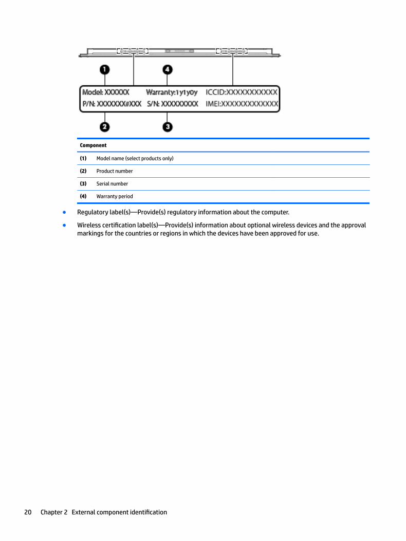
Component
(1) Model name (select products only)
(2) Product number
(3) Serial number
(4) Warranty period
● Regulatory label(s)—Provide(s) regulatory information about the computer.
● Wireless certification label(s)—Provide(s) information about optional wireless devices and the approval markings for the countries or regions in which the devices have been approved for use.
20 Chapter 2 External component identification
3 Illustrated parts catalog
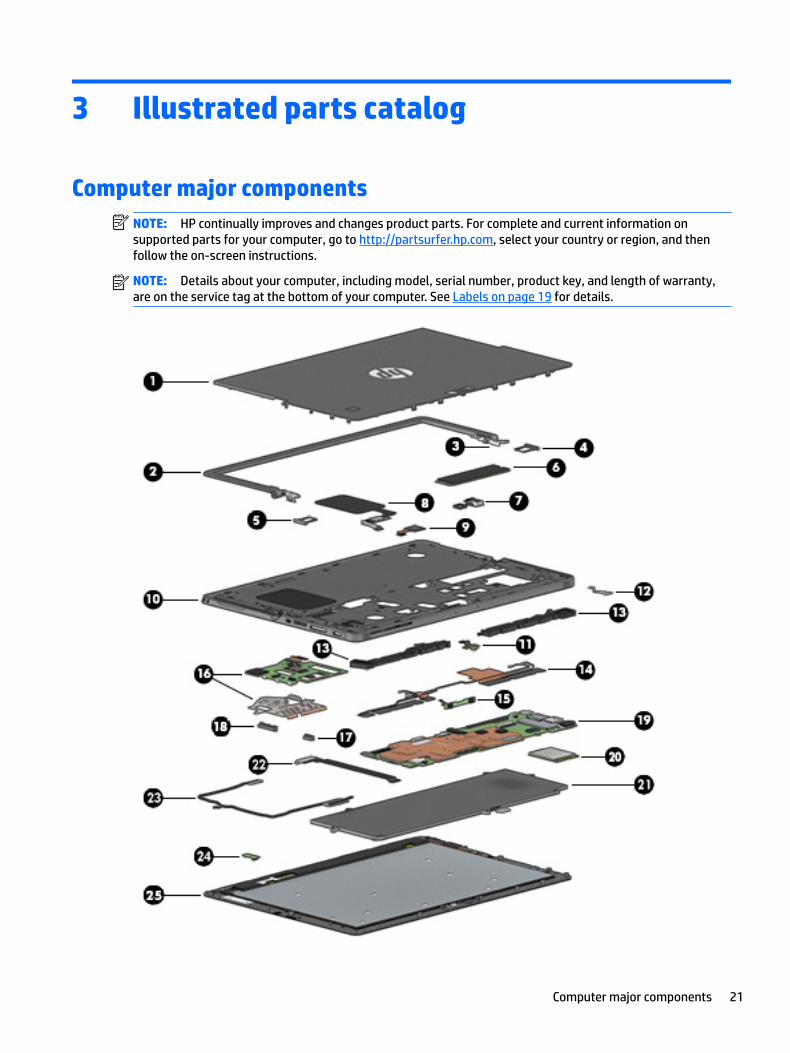
Computer major componentsNOTE: HP continually improves and changes product parts. For complete and current information on supported parts for your computer, go to http://partsurfer.hp.com, select your country or region, and then follow the on-screen instructions.
NOTE: Details about your computer, including model, serial number, product key, and length of warranty, are on the service tag at the bottom of your computer. See Labels on page 19 for details.
Computer major components 21
Item Component Spare part number
(1) Rear cover 918385-001
(2) Kickstand 918394-001
(3) Hinges 918904-001
(4) SIM card tray (included with the Plastics Kit) 918392-001
(5) SD card tray (included with the Plastics Kit) 918392-001
(6) SSD
128 GB M2 SATA-3 918353-001
256 GB Turbo Drive G2 TLC 918354-001
256 GB SATA-3 SED OPAL2 TLC 918356-001
360 GB PCIe TLC 918357-001
512 GB PCIe TLC 918358-001
(7) Rear webcam and flash 918907-001
(8) NFC module and antenna 918399-001
(9) Fingerprint reader (includes cable). The fingerprint reader blank is included in the Plastics Kit.
918398-001
(10) Middle frame 918395-001
(11) Front webcam 918906-001
(12) USB Type-C bracket (included with the Plastics Kit) 918392-001
(13) Speakers 921406-001
(14) Antennas, WLAN dual 918901-001
(15) Microphone board 918387-001
(16) Smart card reader board and bracket 918386-001
(17) Power button (included with the Plastics Kit) 918392-001
(18) Volume button (included with the Plastics Kit) 918392-001
(19) System board
UMA graphics Core M-7Y30 4 GB with Windows operating system and WLAN capability 918345-601
UMA graphics Core i5-7Y54 4 GB with Windows operating system and WLAN capability 918346-601
UMA graphics Core i5-7Y54 8 GB with Windows operating system and WLAN capability 918347-601
UMA graphics Core i5-7Y57 4 GB with Windows operating system and WLAN capability 918348-601
UMA graphics Core i5-7Y57 8 GB with Windows operating system and WLAN capability 918349-601
UMA graphics Core i7-7Y75 8 GB with Windows operating system and WLAN capability 918350-601
UMA graphics Pentium 4410Y 4 GB with Windows operating system and WLAN capability 918351-601
(20) WWAN module (select products only)
Foxconn HP lt4120 LTE/EVDO/HPSA+ with GPS M.2 with antennas 922446-001
22 Chapter 3 Illustrated parts catalog
Item Component Spare part number
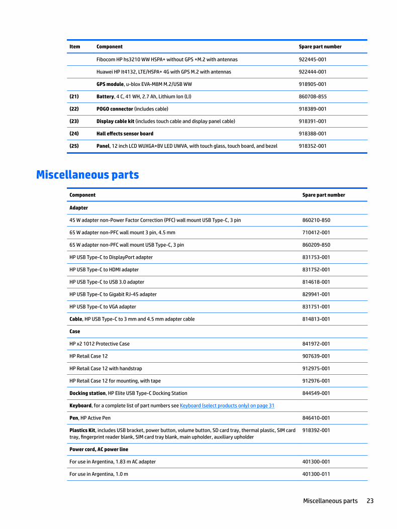
Fibocom HP hs3210 WW HSPA+ without GPS +M.2 with antennas 922445-001
Huawei HP It4132, LTE/HSPA+ 4G with GPS M.2 with antennas 922444-001
GPS module, u-blox EVA-M8M M.2/USB WW 918905-001
(21) Battery, 4 C, 41 WH, 2.7 Ah, Lithium Ion (LI) 860708-855
(22) POGO connector (includes cable) 918389-001
(23) Display cable kit (includes touch cable and display panel cable) 918391-001
(24) Hall effects sensor board 918388-001
(25) Panel, 12 inch LCD WUXGA+BV LED UWVA, with touch glass, touch board, and bezel 918352-001
Miscellaneous parts
Component Spare part number
Adapter
45 W adapter non-Power Factor Correction (PFC) wall mount USB Type-C, 3 pin 860210-850
65 W adapter non-PFC wall mount 3 pin, 4.5 mm 710412-001
65 W adapter non-PFC wall mount USB Type-C, 3 pin 860209-850
HP USB Type-C to DisplayPort adapter 831753-001
HP USB Type-C to HDMI adapter 831752-001
HP USB Type-C to USB 3.0 adapter 814618-001
HP USB Type-C to Gigabit RJ-45 adapter 829941-001
HP USB Type-C to VGA adapter 831751-001
Cable, HP USB Type-C to 3 mm and 4.5 mm adapter cable 814813-001
Case
HP x2 1012 Protective Case 841972-001
HP Retail Case 12 907639-001
HP Retail Case 12 with handstrap 912975-001
HP Retail Case 12 for mounting, with tape 912976-001
Docking station, HP Elite USB Type-C Docking Station 844549-001
Keyboard, for a complete list of part numbers see Keyboard (select products only) on page 31
Pen, HP Active Pen 846410-001
Plastics Kit, includes USB bracket, power button, volume button, SD card tray, thermal plastic, SIM card tray, fingerprint reader blank, SIM card tray blank, main upholder, auxiliary upholder
918392-001
Power cord, AC power line
For use in Argentina, 1.83 m AC adapter 401300-001
For use in Argentina, 1.0 m 401300-011
Miscellaneous parts 23

Component Spare part number
For use in Australia, 1.0 m 213356-013
For use in Brazil, 1.83 m AC adapter 438722-001
For use in Brazil, 1.0 m 438722-008
For use in the People’s Republic of China, 1.83 m AC adapter 286497-001
For use in the People’s Republic of China, 1.0 m 286497-013
For use in Denmark, 1.83 m AC adapter 213353-001
For use in Denmark, 1.0 m 213353-013
For use in Europe, 1.83 m AC adapter 213350-001
For use in Europe, 1.0 m 213350-014
For use in India, 1.83 m AC adapter 404827-001
For use in India, 1.0 m 404827-008
For use in Israel, 1.83 m AC adapter 398063-001
For use in Israel, 1.0 m 398063-008
For use in Italy, 1.83 m AC adapter 213352-001
For use in Italy, 1.0 m 213352-013
Adapter, for use in Japan, 1.0 m 226768-001
For use in Japan, with ground lead 349756-001
For use in Korea, 1.0 m 267836-001
For use in North America, 1.0 m 213349-015
For use in South Africa, 1.83 m AC adapter 361240-001
For use in South Africa, 1.0 m 361240-007
For use in Switzerland, 1.83 m AC adapter 213354-001
For use in Switzerland, 1.0 m 213354-013
For use in Taiwan, 1.83 m AC adapter 393313-001
For use in Taiwan, 1.0 m 393313-007
For use in Thailand, 1.83 m AC adapter 285096-001
For use in Thailand, 1.0 m 285096-012
For use in the United Kingdom and Singapore, 1.83 m AC adapter 213351-001
For use in the United Kingdom, 1.0 m 213351-013
For use in the United States, 1.83 m AC adapter 213349-001
Power cord with duck head
For use in Europe and Korea 854703-001
For use in the United States 854702-001
Screw Kit 918393-001
24 Chapter 3 Illustrated parts catalog

4 Removal and replacement procedures preliminary requirements
Tools requiredYou will need the following tools to complete the removal and replacement procedures:
● Flat-bladed screwdriver
● Magnetic screwdriver
● Phillips P0 and P1 screwdrivers
● Torx T5 screwdriver
● Tweezers
● Thin plastic tool
● Paper clip or thin wire
Service considerationsThe following sections include some of the considerations that you must keep in mind during disassembly and assembly procedures.
NOTE: As you remove each subassembly from the computer, place the subassembly (and all accompanying screws) away from the work area to prevent damage.
Plastic parts
CAUTION: Using excessive force during disassembly and reassembly can damage plastic parts. Use care when handling the plastic
Tools required 25

Cables and connectors
CAUTION: When servicing the computer, be sure that cables are placed in their proper locations during the reassembly process. Improper cable placement can damage the computer.
Cables must be handled with extreme care to avoid damage. Apply only the tension required to unseat or seat the cables during removal and insertion. Handle cables by the connector whenever possible. In all cases, avoid bending, twisting, or tearing cables. Be sure that cables are routed in such a way that they cannot be caught or snagged by parts being removed or replaced. Handle flex cables with extreme care; these cables tear easily.
Drive handling
CAUTION: Drives are fragile components that must be handled with care. To prevent damage to the computer, damage to a drive, or loss of information, observe these precautions:
Before removing or inserting a hard drive, shut down the computer. If you are unsure whether the computer is off or in Hibernation, turn the computer on, and then shut it down through the operating system.
Before handling a drive, be sure that you are discharged of static electricity. While handling a drive, avoid touching the connector.
Before removing a diskette drive or optical drive, be sure that a diskette or disc is not in the drive and be sure that the optical drive tray is closed.
Handle drives on surfaces covered with at least one inch of shock-proof foam.
Avoid dropping drives from any height onto any surface.
Avoid exposing an internal hard drive to products that have magnetic fields, such as monitors or speakers.
Avoid exposing an internal hard drive to products that have magnetic fields, such as monitors or speakers.
Avoid exposing a drive to temperature extremes or liquids.
If a drive must be mailed, place the drive in a bubble pack mailer or other suitable form of protective packaging and label the package “FRAGILE.”
26 Chapter 4 Removal and replacement procedures preliminary requirements
Grounding guidelines
Electrostatic discharge damage
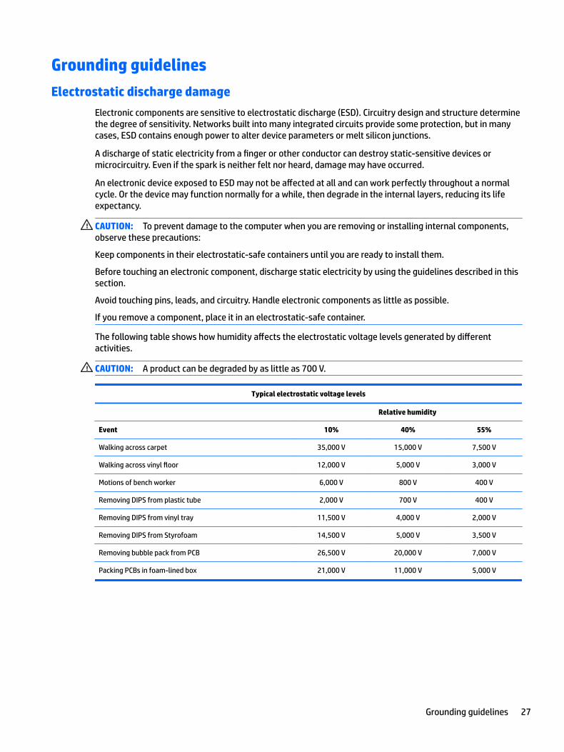
Electronic components are sensitive to electrostatic discharge (ESD). Circuitry design and structure determine the degree of sensitivity. Networks built into many integrated circuits provide some protection, but in many cases, ESD contains enough power to alter device parameters or melt silicon junctions.
A discharge of static electricity from a finger or other conductor can destroy static-sensitive devices or microcircuitry. Even if the spark is neither felt nor heard, damage may have occurred.
An electronic device exposed to ESD may not be affected at all and can work perfectly throughout a normal cycle. Or the device may function normally for a while, then degrade in the internal layers, reducing its life expectancy.
CAUTION: To prevent damage to the computer when you are removing or installing internal components, observe these precautions:
Keep components in their electrostatic-safe containers until you are ready to install them.
Before touching an electronic component, discharge static electricity by using the guidelines described in this section.
Avoid touching pins, leads, and circuitry. Handle electronic components as little as possible.
If you remove a component, place it in an electrostatic-safe container.
The following table shows how humidity affects the electrostatic voltage levels generated by different activities.
CAUTION: A product can be degraded by as little as 700 V.
Typical electrostatic voltage levels
Relative humidity
Event 10% 40% 55%
Walking across carpet 35,000 V 15,000 V 7,500 V
Walking across vinyl floor 12,000 V 5,000 V 3,000 V
Motions of bench worker 6,000 V 800 V 400 V
Removing DIPS from plastic tube 2,000 V 700 V 400 V
Removing DIPS from vinyl tray 11,500 V 4,000 V 2,000 V
Removing DIPS from Styrofoam 14,500 V 5,000 V 3,500 V
Removing bubble pack from PCB 26,500 V 20,000 V 7,000 V
Packing PCBs in foam-lined box 21,000 V 11,000 V 5,000 V
Grounding guidelines 27
Packaging and transporting guidelines
Follow these grounding guidelines when packaging and transporting equipment:
● To avoid hand contact, transport products in static-safe tubes, bags, or boxes.
● Protect ESD-sensitive parts and assemblies with conductive or approved containers or packaging.
● Keep ESD-sensitive parts in their containers until the parts arrive at static-free workstations.
● Place items on a grounded surface before removing items from their containers.
● Always be properly grounded when touching a component or assembly.
● Store reusable ESD-sensitive parts from assemblies in protective packaging or nonconductive foam.
● Use transporters and conveyors made of antistatic belts and roller bushings. Be sure that mechanized equipment used for moving materials is wired to ground and that proper materials are selected to avoid static charging. When grounding is not possible, use an ionizer to dissipate electric charges.
Workstation guidelines
Follow these grounding workstation guidelines:
● Cover the workstation with approved static-shielding material.
● Use a wrist strap connected to a properly grounded work surface and use properly grounded tools and equipment.
● Use conductive field service tools, such as cutters, screwdrivers, and vacuums.
● When fixtures must directly contact dissipative surfaces, use fixtures made only of static safe materials.
● Keep the work area free of nonconductive materials, such as ordinary plastic assembly aids and Styrofoam.
● Handle ESD-sensitive components, parts, and assemblies by the case or PCM laminate. Handle these items only at static-free workstations.
● Avoid contact with pins, leads, or circuitry.
● Turn off power and input signals before inserting or removing connectors or test equipment.
28 Chapter 4 Removal and replacement procedures preliminary requirements

Equipment guidelines
Grounding equipment must include either a wrist strap or a foot strap at a grounded workstation.
● When seated, wear a wrist strap connected to a grounded system. Wrist straps are flexible straps with a minimum of one megohm ±10% resistance in the ground cords. To provide proper ground, wear a strap snugly against the skin at all times. On grounded mats with banana-plug connectors, use alligator clips to connect a wrist strap.
● When standing, use foot straps and a grounded floor mat. Foot straps (heel, toe, or boot straps) can be used at standing workstations and are compatible with most types of shoes or boots. On conductive floors or dissipative floor mats, use foot straps on both feet with a minimum of one megohm resistance between the operator and ground. To be effective, the conductive must be worn in contact with the skin.
The following grounding equipment is recommended to prevent electrostatic damage:
● Antistatic tape
● Antistatic smocks, aprons, and sleeve protectors
● Conductive bins and other assembly or soldering aids
● Nonconductive foam
● Conductive tabletop workstations with ground cords of one megohm resistance
● Static-dissipative tables or floor mats with hard ties to the ground
● Field service kits
● Static awareness labels
● Material-handling packages
● Nonconductive plastic bags, tubes, or boxes
● Metal tote boxes
● Electrostatic voltage levels and protective materials
The following table lists the shielding protection provided by antistatic bags and floor mats.
Material Use Voltage protection level
Antistatic plastics Bags 1,500 V
Carbon-loaded plastic Floor mats 7,500 V
Metallized laminate Floor mats 5,000 V
Grounding guidelines 29
5 Removal and replacement procedures for Customer Self-Repair parts
This chapter provides removal and replacement procedures for Customer Self-Repair parts.
NOTE: The Customer Self-Repair program is not available in all locations. Installing a part not supported by the Customer Self-Repair program may void your warranty. Check your warranty to determine if Customer Self-Repair is supported in your location.
Component replacement proceduresNOTE: Details about your computer, including model, serial number, product key, and length of warranty, are on the service tag at the bottom of your computer. See Labels on page 19 for details.
NOTE: HP continually improves and changes product parts. For complete and current information on supported parts for your computer, go to http://partsurfer.hp.com, select your country or region, and then follow the on-screen instructions.
NOTE: There are a number of magnets located on the computer. The screws may attach to the magnets after being unscrewed.
There may be as many as 10 screws that must be removed, replaced, and/or loosened when servicing Customer Self-Repair parts. Make special note of the screw sizes and locations during removal and replacement.
30 Chapter 5 Removal and replacement procedures for Customer Self-Repair parts
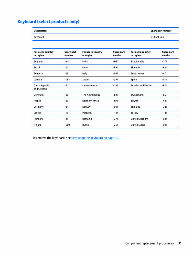
Keyboard (select products only)
Description Spare part number
Keyboard 918321-xxx
For use in country or region
Spare part number
For use in country or region
Spare part number
For use in country or region
Spare part number
Belgium -A41 India -D61 Saudi Arabia -171
Brazil -201 Israel -BB1 Slovenia -BA1
Bulgaria -261 Italy -061 South Korea -AD1
Canada -DB1 Japan -291 Spain -071
Czech Republic and Slovakia
-FL1 Latin America -161 Sweden and Finland -B71
Denmark -081 The Netherlands -B31 Switzerland -BG1
France -051 Northern Africa -FP1 Taiwan -AB1
Germany -041 Norway -091 Thailand -281
Greece -151 Portugal -131 Turkey -141
Hungary -211 Romania -271 United Kingdom -031
Iceland -DD1 Russia -251 United States -001
To remove the keyboard, see Removing the keyboard on page 14.
Component replacement procedures 31
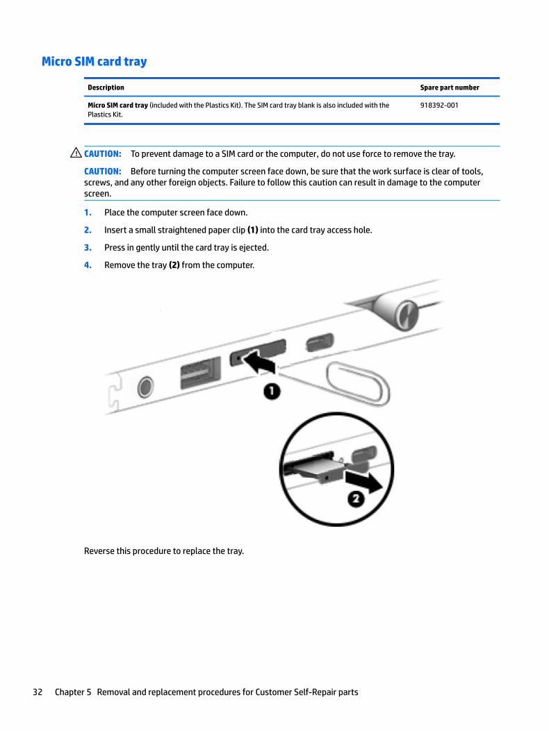
Micro SIM card tray
Description Spare part number
Micro SIM card tray (included with the Plastics Kit). The SIM card tray blank is also included with the Plastics Kit.
918392-001
CAUTION: To prevent damage to a SIM card or the computer, do not use force to remove the tray.
CAUTION: Before turning the computer screen face down, be sure that the work surface is clear of tools, screws, and any other foreign objects. Failure to follow this caution can result in damage to the computer screen.
1. Place the computer screen face down.
2. Insert a small straightened paper clip (1) into the card tray access hole.
3. Press in gently until the card tray is ejected.
4. Remove the tray (2) from the computer.
Reverse this procedure to replace the tray.
32 Chapter 5 Removal and replacement procedures for Customer Self-Repair parts
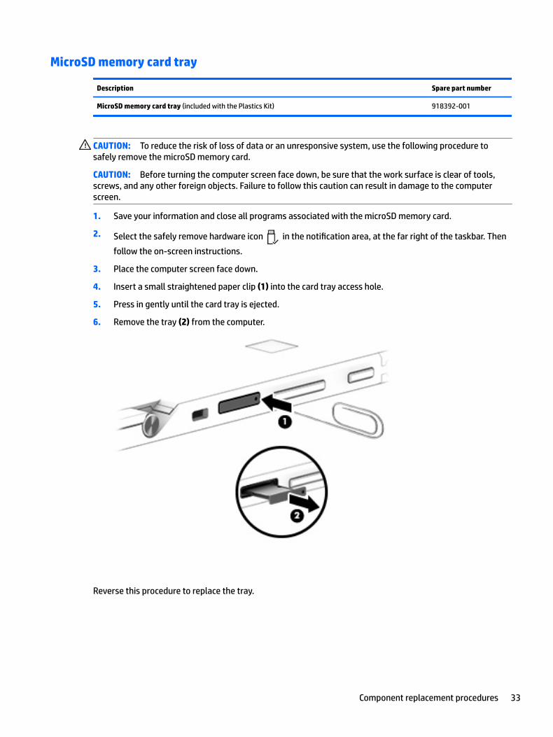
MicroSD memory card tray
Description Spare part number
MicroSD memory card tray (included with the Plastics Kit) 918392-001
CAUTION: To reduce the risk of loss of data or an unresponsive system, use the following procedure to safely remove the microSD memory card.
CAUTION: Before turning the computer screen face down, be sure that the work surface is clear of tools, screws, and any other foreign objects. Failure to follow this caution can result in damage to the computer screen.
1. Save your information and close all programs associated with the microSD memory card.
2. Select the safely remove hardware icon in the notification area, at the far right of the taskbar. Then
follow the on-screen instructions.
3. Place the computer screen face down.
4. Insert a small straightened paper clip (1) into the card tray access hole.
5. Press in gently until the card tray is ejected.
6. Remove the tray (2) from the computer.
Reverse this procedure to replace the tray.
Component replacement procedures 33

Rear cover
Description Spare part number
Rear cover 918385-001
CAUTION: Before turning the computer screen face down, be sure that the work surface is clear of tools, screws, and any other foreign objects. Failure to follow this caution can result in damage to the computer screen.
Before removing the rear cover, follow these steps:
1. Turn off the computer. If you are unsure whether the computer is off or in Hibernation, turn the computer on, and then shut it down through the operating system.
2. Disconnect the power from the computer by unplugging the power cord from the computer.
3. Disconnect all external devices from the computer.
4. Remove the keyboard (select products only) (see Keyboard (select products only) on page 31.
1. Turn the computer screen face down on a flat surface, with the rear webcam facing you.
NOTE: The rear cover is secured by clips (1) around the outer edge and across the middle of the cover.
2. Lift the kickstand (2).
3. Place a thin tool at the bottom corner (3) to release the cover from the computer.
4. Lift the bottom edge (4) to release the clips securing the cover to the computer. Continue to lift the cover until all of the clips are released.
5. Slide the cover (5) toward you to remove it from the computer.
Reverse this procedure to replace the cover.
34 Chapter 5 Removal and replacement procedures for Customer Self-Repair parts

Disconnecting the battery
Description Spare part number
Battery, 4 C, 41 WH, 2.7 Ah, LI 860708-855
CAUTION: Disconnecting a battery that is the sole power source for the device can cause loss of information. To prevent loss of information, save your work or shut down the device through the operating system before disconnecting the battery.
IMPORTANT: Make special note of each screw size and location during removal and replacement.
Before removing the display panel, follow these steps:
1. Turn off the computer. If you are unsure whether the computer is off or in Hibernation, turn the computer on, and then shut it down through the operating system.
2. Disconnect the power from the computer by unplugging the power cord from the computer.
3. Disconnect all external devices from the computer.
4. Remove the following components:
a. Keyboard (select products only) (see Keyboard (select products only) on page 31)
b. Rear cover (see Rear cover on page 34)
Disconnect the battery:
1. Insert a thin tool to release the battery cable (1).
2. Disconnect the battery cable (2).
Reverse this procedure to reconnect the battery.
Component replacement procedures 35
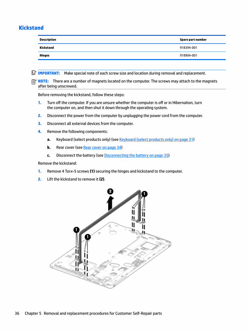
Kickstand
Description Spare part number
Kickstand 918394-001
Hinges 918904-001
IMPORTANT: Make special note of each screw size and location during removal and replacement.
NOTE: There are a number of magnets located on the computer. The screws may attach to the magnets after being unscrewed.
Before removing the kickstand, follow these steps:
1. Turn off the computer. If you are unsure whether the computer is off or in Hibernation, turn the computer on, and then shut it down through the operating system.
2. Disconnect the power from the computer by unplugging the power cord from the computer.
3. Disconnect all external devices from the computer.
4. Remove the following components:
a. Keyboard (select products only) (see Keyboard (select products only) on page 31)
b. Rear cover (see Rear cover on page 34)
c. Disconnect the battery (see Disconnecting the battery on page 35)
Remove the kickstand:
1. Remove 4 Torx-5 screws (1) securing the hinges and kickstand to the computer.
2. Lift the kickstand to remove it (2).
36 Chapter 5 Removal and replacement procedures for Customer Self-Repair parts
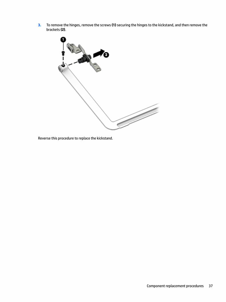
3. To remove the hinges, remove the screws (1) securing the hinges to the kickstand, and then remove the brackets (2).
Reverse this procedure to replace the kickstand.
Component replacement procedures 37

SSD
Description Spare part number
SSD
128 GB M2 SATA-3 918353-001
256 GB Turbo Drive G2 TLC 918354-001
256 GB SATA-3 SED OPAL2 TLC 918356-001
360 GB PCIe TLC 918357-001
512 GB PCIe TLC 918358-001
IMPORTANT: Make special note of each screw size and location during removal and replacement.
Before removing the SSD, follow these steps:
1. Turn off the computer. If you are unsure whether the computer is off or in Hibernation, turn the computer on, and then shut it down through the operating system.
2. Disconnect the power from the computer by unplugging the power cord from the computer.
3. Disconnect all external devices from the computer.
4. Remove the following components:
a. Keyboard (select products only) (see Keyboard (select products only) on page 31)
b. Micro SIM card tray (see Micro SIM card tray on page 32)
c. MicroSD card tray (see MicroSD memory card tray on page 33)
d. Rear cover (see Rear cover on page 34)
e. Disconnect the battery (see Disconnecting the battery on page 35)
Remove the SSD:
1. Remove 1 Phillips M2.0x2.0 screw (1).
38 Chapter 5 Removal and replacement procedures for Customer Self-Repair parts

2. Slide the SSD (2) to the right, and then lift the SSD to remove it.
Reverse this procedure to replace the SSD.
Component replacement procedures 39

6 Removal and replacement procedures for Authorized Service Provider parts
This chapter provides removal and replacement procedures for Authorized Service Provider only parts.
CAUTION: Components described in this chapter should only be accessed by an authorized service provider. Accessing these parts can damage the computer or void the warranty.
CAUTION: This computer does not have user-replaceable parts. Only HP authorized service providers should perform the removal and replacement procedures described here. Accessing the internal part could damage the computer or void the warranty.
Component replacement proceduresNOTE: Details about your computer, including model, serial number, product key, and length of warranty, are on the service tag at the bottom of your computer. See Labels on page 19 for details.
NOTE: HP continually improves and changes product parts. For complete and current information on supported parts for your computer, go to http://partsurfer.hp.com, select your country or region, and then follow the on-screen instructions.
NOTE: There are a number of magnets located on the computer. The screws may attach to the magnets after being unscrewed.
There are as many as 34 screws that must be removed, replaced, and/or loosened when servicing Authorized Service Provider only parts. Make special note of each screw size and location during removal and replacement.
40 Chapter 6 Removal and replacement procedures for Authorized Service Provider parts

WWAN or GPS module
IMPORTANT: Make special note of each screw size and location during removal and replacement.
Description Spare part number
WWAN module (select products only)
Foxconn HP lt4120 LTE/EVDO/HPSA+ with GPS M.2 with antennas 922446-001
Fibocom HP hs3210 WW HSPA+ without GPS +M.2 with antennas 922445-001
Huawei HP It4132, LTE/HSPA+ 4G with GPS M.2 with antennas 922444-001
GPS module, u-blox EVA-M8M M.2/USB WW 918905-001
Before removing the WWAN or GPS module, follow these steps:
1. Turn off the computer. If you are unsure whether the computer is off or in Hibernation, turn the computer on, and then shut it down through the operating system.
2. Disconnect the power from the computer by unplugging the power cord from the computer.
3. Disconnect all external devices from the computer.
4. Remove the following components:
a. Keyboard (select products only) (see Keyboard (select products only) on page 31)
b. Micro SIM card tray (see Micro SIM card tray on page 32)
c. MicroSD card tray (see MicroSD memory card tray on page 33)
d. Rear cover (see Rear cover on page 34)
e. Disconnect the battery (see Disconnecting the battery on page 35)
Remove the WWAN or GPS module:
NOTE: Before removing the WWAN or GPS module, note which antennas is AUX and which is MAIN. These connectors are not always located on the same side of a module; they can vary depending upon the supplier. When you replace the module, the MAIN antenna should be attached to the connector marked MAIN and the AUX antenna should be attached to the connector marked AUX.
▲ Disconnect the 2 antenna cables (1), remove 1 Phillips M2.0x2.0 screw (2), and then remove the module (3).
NOTE: The GPS module will be connected to the WWAN AUX antenna cable only.
Component replacement procedures 41
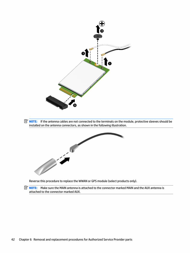
NOTE: If the antenna cables are not connected to the terminals on the module, protective sleeves should be installed on the antenna connectors, as shown in the following illustration.
Reverse this procedure to replace the WWAN or GPS module (select products only).
NOTE: Make sure the MAIN antenna is attached to the connector marked MAIN and the AUX antenna is attached to the connector marked AUX.
42 Chapter 6 Removal and replacement procedures for Authorized Service Provider parts

Rear webcam and flash
Description Spare part number
Rear webcam and flash 918907-001
IMPORTANT: Make special note of each screw size and location during removal and replacement.
Before removing the rear webcam, follow these steps:
1. Turn off the computer. If you are unsure whether the computer is off or in Hibernation, turn the computer on, and then shut it down through the operating system.
2. Disconnect the power from the computer by unplugging the power cord from the computer.
3. Disconnect all external devices from the computer.
4. Remove the following components:
a. Keyboard (select products only) (see Keyboard (select products only) on page 31)
b. Micro SIM card tray (see Micro SIM card tray on page 32)
c. MicroSD card tray (see MicroSD memory card tray on page 33)
d. Rear cover (see Rear cover on page 34)
e. Disconnect the battery (see Disconnecting the battery on page 35)
Remove the rear webcam:
CAUTION: Use care to prevent damaging the zero-insertion force (ZIF) connector and ribbon cable.
1. Remove the conductive tape (1) from the rear webcam.
Component replacement procedures 43

2. Disconnect the ZIF connector and release the rear webcam cable (2) from the system board, and then lift the rear webcam and flash (3) to remove it.
Reverse this procedure to replace the rear webcam.
44 Chapter 6 Removal and replacement procedures for Authorized Service Provider parts
Display panel
Description Spare part number
Panel, 12 inch LCD WUXGA+BV LED UWVA, (includes touch glass, touch board, and bezel) 918352-001
Display cable kit, (includes touch cable and display panel cable) 918391-001
IMPORTANT: Make special note of each screw size and location during removal and replacement.
Before removing the display panel, follow these steps:
1. Turn off the computer. If you are unsure whether the computer is off or in Hibernation, turn the computer on, and then shut it down through the operating system.
2. Disconnect the power from the computer by unplugging the power cord from the computer.
3. Disconnect all external devices from the computer.
4. Remove the following components:
a. Keyboard (select products only) (see Keyboard (select products only) on page 31)
b. Micro SIM card tray (see Micro SIM card tray on page 32)
c. MicroSD card tray (see MicroSD memory card tray on page 33)
d. Rear cover (see Rear cover on page 34)
e. Disconnect the battery (see Disconnecting the battery on page 35)
f. Kickstand (see Kickstand on page 36)
g. SSD (see SSD on page 38)
Remove the display panel:
1. Remove the 8 Torx T5 3 mm screws (1) securing the sides and bottom.
2. Remove the 5 Torx T5 5 mm screws (2) securing the top.
Component replacement procedures 45

3. Remove the Torx T5 6 mm screw (3) beside the fingerprint reader.
4. Release the following cables from the system board:
1. Right speaker
2. WWAN module or GPS module antenna
3. Rear webcam
5. Release the following cables from the system board:
46 Chapter 6 Removal and replacement procedures for Authorized Service Provider parts

1. Left speaker
2. WLAN card antennas
3. Smart card
NOTE: The display cable and touch control cable are still connected to the display and system board. Separate the middle frame and display only enough to disconnect the cables.
6. Insert a thin tool (1) in the video cable cutout, and then move the display panel (2) away from the middle frame.
Component replacement procedures 47
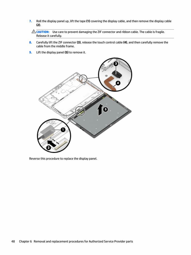
7. Roll the display panel up, lift the tape (1) covering the display cable, and then remove the display cable (2).
CAUTION: Use care to prevent damaging the ZIF connector and ribbon cable. The cable is fragile. Release it carefully.
8. Carefully lift the ZIF connector (3), release the touch control cable (4), and then carefully remove the cable from the middle frame.
9. Lift the display panel (5) to remove it.
Reverse this procedure to replace the display panel.
48 Chapter 6 Removal and replacement procedures for Authorized Service Provider parts
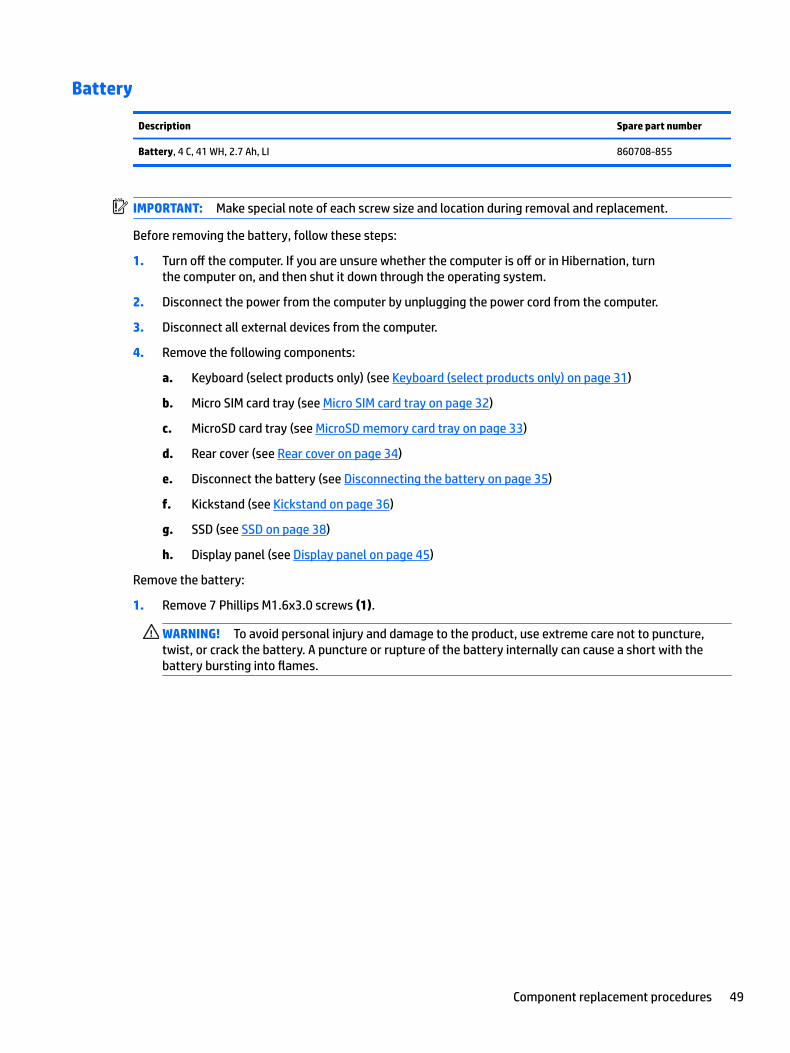
Battery
Description Spare part number
Battery, 4 C, 41 WH, 2.7 Ah, LI 860708-855
IMPORTANT: Make special note of each screw size and location during removal and replacement.
Before removing the battery, follow these steps:
1. Turn off the computer. If you are unsure whether the computer is off or in Hibernation, turn the computer on, and then shut it down through the operating system.
2. Disconnect the power from the computer by unplugging the power cord from the computer.
3. Disconnect all external devices from the computer.
4. Remove the following components:
a. Keyboard (select products only) (see Keyboard (select products only) on page 31)
b. Micro SIM card tray (see Micro SIM card tray on page 32)
c. MicroSD card tray (see MicroSD memory card tray on page 33)
d. Rear cover (see Rear cover on page 34)
e. Disconnect the battery (see Disconnecting the battery on page 35)
f. Kickstand (see Kickstand on page 36)
g. SSD (see SSD on page 38)
h. Display panel (see Display panel on page 45)
Remove the battery:
1. Remove 7 Phillips M1.6x3.0 screws (1).
WARNING! To avoid personal injury and damage to the product, use extreme care not to puncture, twist, or crack the battery. A puncture or rupture of the battery internally can cause a short with the battery bursting into flames.
Component replacement procedures 49
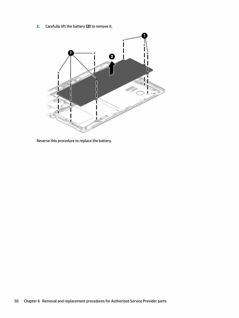
2. Carefully lift the battery (2) to remove it.
Reverse this procedure to replace the battery.
50 Chapter 6 Removal and replacement procedures for Authorized Service Provider parts

Hall effects sensor board
Description Spare part number
Hall effects sensor board 918388-001
IMPORTANT: Make special note of each screw size and location during removal and replacement.
Before removing the Hall effects sensor board, follow these steps:
1. Turn off the computer. If you are unsure whether the computer is off or in Hibernation, turn the computer on, and then shut it down through the operating system.
2. Disconnect the power from the computer by unplugging the power cord from the computer.
3. Disconnect all external devices from the computer.
4. Remove the following components:
a. Keyboard (select products only) (see Keyboard (select products only) on page 31)
b. Micro SIM card tray (see Micro SIM card tray on page 32)
c. MicroSD card tray (see MicroSD memory card tray on page 33)
d. Rear cover (see Rear cover on page 34)
e. Disconnect the battery (see Disconnecting the battery on page 35)
f. Kickstand (see Kickstand on page 36)
g. SSD (see SSD on page 38)
h. Display panel (see Display panel on page 45)
i. Battery (see Battery on page 49)
Remove the Hall effects sensor board:
1. Disconnect the display cable (1) from the Hall effects sensor board.
2. Remove the Phillips screw (2) securing board.
Component replacement procedures 51
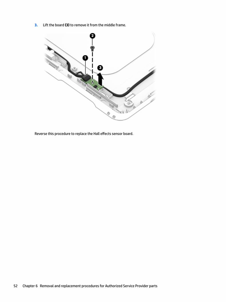
3. Lift the board (3) to remove it from the middle frame.
Reverse this procedure to replace the Hall effects sensor board.
52 Chapter 6 Removal and replacement procedures for Authorized Service Provider parts

NFC module
Description Spare part number
NFC module and antenna 918399-001
IMPORTANT: Make special note of each screw size and location during removal and replacement.
Before removing the NFC module, follow these steps:
1. Turn off the computer. If you are unsure whether the computer is off or in Hibernation, turn the computer on, and then shut it down through the operating system.
2. Disconnect the power from the computer by unplugging the power cord from the computer.
3. Disconnect all external devices from the computer.
4. Remove the following components:
a. Keyboard (select products only) (see Keyboard (select products only) on page 31)
b. Micro SIM card tray (see Micro SIM card tray on page 32)
c. MicroSD card tray (see MicroSD memory card tray on page 33)
d. Rear cover (see Rear cover on page 34)
e. Disconnect the battery (see Disconnecting the battery on page 35)
f. Kickstand (see Kickstand on page 36)
g. SSD (see SSD on page 38)
h. Display panel (see Display panel on page 45)
i. Battery (see Battery on page 49)
Remove the NFC module:
1. Remove the clear plastic tape (1) covering the NFC cable and the fingerprint reader board, and then disconnect the cable from the fingerprint reader board (2).
2. Remove the clear plastic tape (3) securing the NFC cable to the middle frame.
NOTE: The tape can be reused.
Component replacement procedures 53

3. Carefully peel and lift the NFC antenna (4) to remove it.
Reverse this procedure to replace the NFC module.
54 Chapter 6 Removal and replacement procedures for Authorized Service Provider parts

System board
Description Spare part number
System board
UMA graphics Core M-7Y30 4 GB with Windows operating system and WLAN capability 918345-601
UMA graphics Core i5-7Y54 4 GB with Windows operating system and WLAN capability 918346-601
UMA graphics Core i5-7Y54 8 GB with Windows operating system and WLAN capability 918347-601
UMA graphics Core i5-7Y57 4 GB with Windows operating system and WLAN capability 918348-601
UMA graphics Core i5-7Y57 8 GB with Windows operating system and WLAN capability 918349-601
UMA graphics Core i7-7Y75 8 GB with Windows operating system and WLAN capability 918350-601
UMA graphics Pentium 4410Y 4 GB with Windows operating system and WLAN capability 918351-601
USB Type-C bracket (included with the Plastics Kit) 918392-001
POGO connector (includes cable) 918389-001
Microphone board 918387-001
Front webcam 918906-001
IMPORTANT: Make special note of each screw size and location during removal and replacement.
Before removing the system board, follow these steps:
1. Turn off the computer. If you are unsure whether the computer is off or in Hibernation, turn the computer on, and then shut it down through the operating system.
2. Disconnect the power from the computer by unplugging the power cord from the computer.
3. Disconnect all external devices from the computer.
4. Remove the following components:
a. Keyboard (select products only) (see Keyboard (select products only) on page 31)
b. Micro SIM card tray (see Micro SIM card tray on page 32)
c. MicroSD card tray (see MicroSD memory card tray on page 33)
d. Rear cover (see Rear cover on page 34)
e. Disconnect the battery (see Disconnecting the battery on page 35)
f. Kickstand (see Kickstand on page 36)
g. SSD (see SSD on page 38)
h. Display panel (see Display panel on page 45)
i. Battery (see Battery on page 49)
Remove the system board:
1. Remove the 2 Phillips M1.6x2.0 screws (1) securing the POGO cable.
2. Use a thin tool (2) to release the POGO cable from the glue securing it.
Component replacement procedures 55
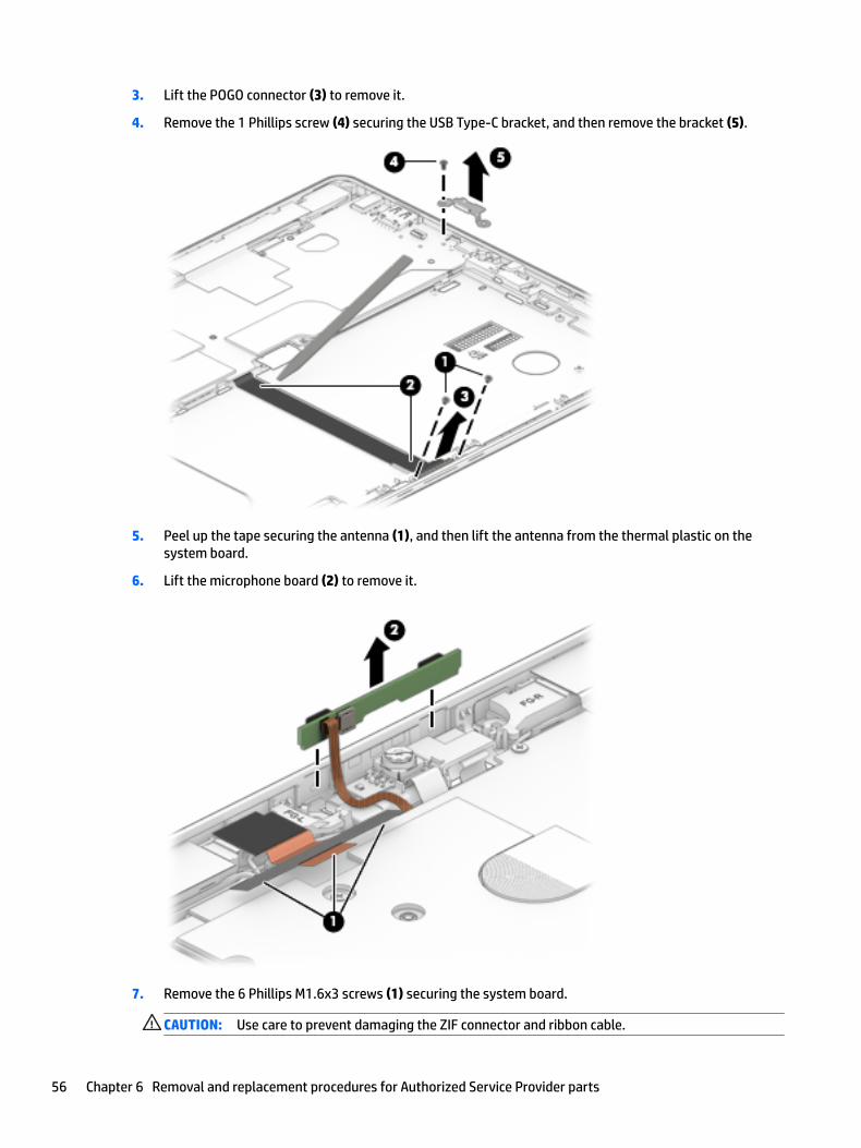
3. Lift the POGO connector (3) to remove it.
4. Remove the 1 Phillips screw (4) securing the USB Type-C bracket, and then remove the bracket (5).
5. Peel up the tape securing the antenna (1), and then lift the antenna from the thermal plastic on the system board.
6. Lift the microphone board (2) to remove it.
7. Remove the 6 Phillips M1.6x3 screws (1) securing the system board.
CAUTION: Use care to prevent damaging the ZIF connector and ribbon cable.
56 Chapter 6 Removal and replacement procedures for Authorized Service Provider parts
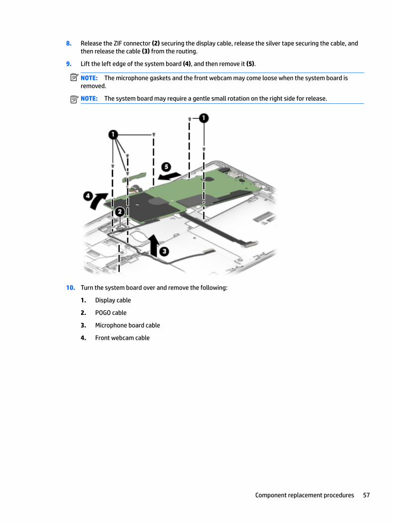
8. Release the ZIF connector (2) securing the display cable, release the silver tape securing the cable, and then release the cable (3) from the routing.
9. Lift the left edge of the system board (4), and then remove it (5).
NOTE: The microphone gaskets and the front webcam may come loose when the system board is removed.
NOTE: The system board may require a gentle small rotation on the right side for release.
10. Turn the system board over and remove the following:
1. Display cable
2. POGO cable
3. Microphone board cable
4. Front webcam cable
Component replacement procedures 57

Reverse this procedure to replace the system board.
POGO connector
Description Spare part number
POGO connector (includes cable) 918389-001
The POGO connector is removed as part of the system board removal. See System board on page 55.
Microphone board
Description Spare part number
Microphone board 918387-001
The microphone board is removed as part of the system board removal. See System board on page 55.
58 Chapter 6 Removal and replacement procedures for Authorized Service Provider parts
Front webcam
Description Spare part number
Front webcam 918906-001
The front webcam is removed as part of the system board removal. See System board on page 55.
Fingerprint reader board
Description Spare part number
Fingerprint reader board (includes cable) 918398-001
Fingerprint reader blank (included with the Plastics Kit) 918392-001
IMPORTANT: Make special note of each screw size and location during removal and replacement.
Before removing the fingerprint reader board, follow these steps:
1. Turn off the computer. If you are unsure whether the computer is off or in Hibernation, turn the computer on, and then shut it down through the operating system.
2. Disconnect the power from the computer by unplugging the power cord from the computer.
3. Disconnect all external devices from the computer.
4. Remove the following components:
a. Keyboard (select products only) (see Keyboard (select products only) on page 31)
b. Micro SIM card tray (see Micro SIM card tray on page 32)
c. MicroSD card tray (see MicroSD memory card tray on page 33)
d. Rear cover (see Rear cover on page 34)
e. Disconnect the battery (see Disconnecting the battery on page 35)
f. Kickstand (see Kickstand on page 36)
g. SSD (see SSD on page 38)
h. Display panel (see Display panel on page 45)
i. Battery (see Battery on page 49)
j. System board (see System board on page 55)
Remove the fingerprint reader board:
CAUTION: Use care to prevent damaging the ZIF connector and ribbon cable.
1. Open the ZIF connector (1) to release the cable, and then remove the fingerprint reader board cable (2).
Component replacement procedures 59
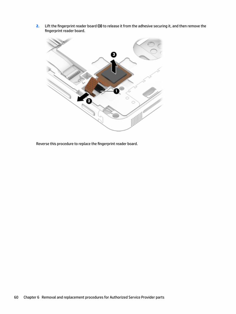
2. Lift the fingerprint reader board (3) to release it from the adhesive securing it, and then remove the fingerprint reader board.
Reverse this procedure to replace the fingerprint reader board.
60 Chapter 6 Removal and replacement procedures for Authorized Service Provider parts

Smart card reader board and bracket
Description Spare part number
Smart card reader board and bracket 918386-001
IMPORTANT: Make special note of each screw size and location during removal and replacement.
Before removing the smart card reader board and bracket, follow these steps:
1. Turn off the computer. If you are unsure whether the computer is off or in Hibernation, turn the computer on, and then shut it down through the operating system.
2. Disconnect the power from the computer by unplugging the power cord from the computer.
3. Disconnect all external devices from the computer.
4. Remove the following components:
a. Keyboard (select products only) (see Keyboard (select products only) on page 31)
b. Micro SIM card tray (see Micro SIM card tray on page 32)
c. MicroSD card tray (see MicroSD memory card tray on page 33)
d. Rear cover (see Rear cover on page 34)
e. Disconnect the battery (see Disconnecting the battery on page 35)
f. Kickstand (see Kickstand on page 36)
g. SSD (see SSD on page 38)
h. Display panel (see Display panel on page 45)
i. Battery (see Battery on page 49)
j. System board (see System board on page 55)
Remove the smart card reader board:
CAUTION: Use care to prevent damaging the ZIF connectors and ribbon cables.
1. Open the ZIF connector (1), and then release the ribbon cable (2).
Component replacement procedures 61

2. Remove the Phillips M1.6x3 screw (1), and then lift the bracket (2).
NOTE: The copper antenna tapes attached to the bracket have a crease for maximum antenna performance. If you are replacing the bracket allow space for that crease when you reapply the antenna tapes.
3. If you need to replace the bracket, remove copper antenna tapes (3), and remove the bracket.
4. Remove the Phillips M1.6x3 screw (1) securing the smart card reader board.
62 Chapter 6 Removal and replacement procedures for Authorized Service Provider parts
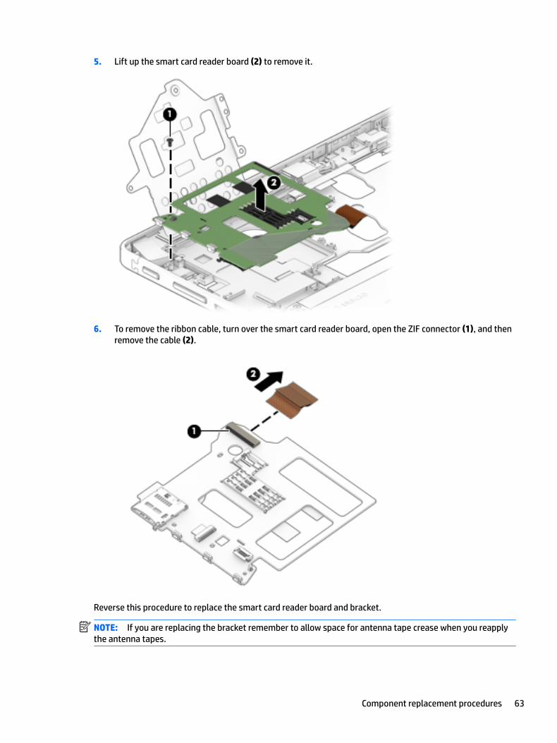
5. Lift up the smart card reader board (2) to remove it.
6. To remove the ribbon cable, turn over the smart card reader board, open the ZIF connector (1), and then remove the cable (2).
Reverse this procedure to replace the smart card reader board and bracket.
NOTE: If you are replacing the bracket remember to allow space for antenna tape crease when you reapply the antenna tapes.
Component replacement procedures 63
Volume button
Description
Volume button (included with the Plastics Kit) 918392-001
IMPORTANT: Make special note of each screw size and location during removal and replacement.
Before removing the volume button, follow these steps:
1. Turn off the computer. If you are unsure whether the computer is off or in Hibernation, turn the computer on, and then shut it down through the operating system.
2. Disconnect the power from the computer by unplugging the power cord from the computer.
3. Disconnect all external devices from the computer.
4. Remove the following components:
a. Keyboard (select products only) (see Keyboard (select products only) on page 31)
b. Micro SIM card tray (see Micro SIM card tray on page 32)
c. MicroSD card tray (see MicroSD memory card tray on page 33)
d. Rear cover (see Rear cover on page 34)
e. Disconnect the battery (see Disconnecting the battery on page 35)
f. Kickstand (see Kickstand on page 36)
g. SSD (see SSD on page 38)
h. Display panel (see Display panel on page 45)
i. Battery (see Battery on page 49)
j. System board (see System board on page 55)
k. Smart card reader board (see Smart card reader board and bracket on page 61)
Remove the volume button:
▲ Push the button in to remove it from the frame.
64 Chapter 6 Removal and replacement procedures for Authorized Service Provider parts
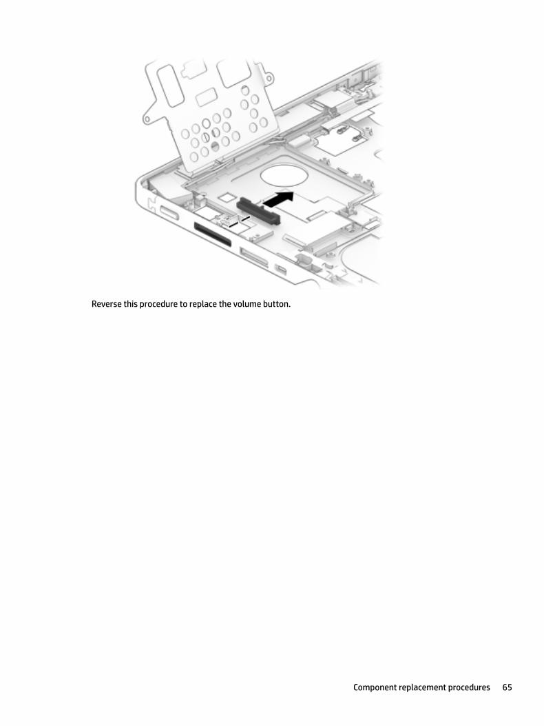
Reverse this procedure to replace the volume button.
Component replacement procedures 65

Power button
Description
Power button (included with the Plastics Kit) 918392-001
IMPORTANT: Make special note of each screw size and location during removal and replacement.
Before removing the power button, follow these steps:
1. Turn off the computer. If you are unsure whether the computer is off or in Hibernation, turn the computer on, and then shut it down through the operating system.
2. Disconnect the power from the computer by unplugging the power cord from the computer.
3. Disconnect all external devices from the computer.
4. Remove the following components:
a. Keyboard (select products only) (see Keyboard (select products only) on page 31)
b. Micro SIM card tray (see Micro SIM card tray on page 32)
c. MicroSD card tray (see MicroSD memory card tray on page 33)
d. Rear cover (see Rear cover on page 34)
e. Disconnect the battery (see Disconnecting the battery on page 35)
f. Kickstand (see Kickstand on page 36)
g. SSD (see SSD on page 38)
h. Display panel (see Display panel on page 45)
i. Battery (see Battery on page 49)
j. System board (see System board on page 55)
k. Smart card reader board (see Smart card reader board and bracket on page 61)
Remove the power button:
▲ Push the button in to remove it from the frame.
66 Chapter 6 Removal and replacement procedures for Authorized Service Provider parts

Reverse this procedure to replace the power button.
Component replacement procedures 67

Speakers
Description Spare part number
Speakers 921406-001
IMPORTANT: Make special note of each screw size and location during removal and replacement
Before removing the speakers, follow these steps:
1. Turn off the computer. If you are unsure whether the computer is off or in Hibernation, turn the computer on, and then shut it down through the operating system.
2. Disconnect the power from the computer by unplugging the power cord from the computer.
3. Disconnect all external devices from the computer.
4. Remove the following components:
a. Keyboard (select products only) (see Keyboard (select products only) on page 31)
b. Micro SIM card tray (see Micro SIM card tray on page 32)
c. MicroSD card tray (see MicroSD memory card tray on page 33)
d. Rear cover (see Rear cover on page 34)
e. Disconnect the battery (see Disconnecting the battery on page 35)
f. Kickstand (see Kickstand on page 36)
g. SSD (see SSD on page 38)
h. Display panel (see Display panel on page 45)
i. Battery (see Battery on page 49)
j. System board (see System board on page 55)
Remove the speakers:
1. Lift the adhesive (1) securing the left speaker, and then lift the adhesive (2) securing the right speaker.
68 Chapter 6 Removal and replacement procedures for Authorized Service Provider parts

2. Release the antenna wires (3) from the routing, and then lift the speakers (4) to remove them.
Reverse this procedure to replace the speakers.
Component replacement procedures 69

Antennas
Description Spare part number
Antennas, WLAN dual 918901-001
IMPORTANT: Make special note of each screw size and location during removal and replacement.
Before removing the antennas, follow these steps:
1. Turn off the computer. If you are unsure whether the computer is off or in Hibernation, turn the computer on, and then shut it down through the operating system.
2. Disconnect the power from the computer by unplugging the power cord from the computer.
3. Disconnect all external devices from the computer.
4. Remove the following components:
a. Keyboard (select products only) (see Keyboard (select products only) on page 31)
b. Micro SIM card tray (see Micro SIM card tray on page 32)
c. MicroSD card tray (see MicroSD memory card tray on page 33)
d. Rear cover (see Rear cover on page 34)
e. Disconnect the battery (see Disconnecting the battery on page 35)
f. Kickstand (see Kickstand on page 36)
g. SSD (see SSD on page 38)
h. Display panel (see Display panel on page 45)
i. Battery (see Battery on page 49)
j. System board (see System board on page 55)
k. Speakers (see Speakers on page 68)
Remove the antennas:
NOTE: The copper antenna tapes have a crease for maximum antenna performance. Allow space for that crease when you reapply the antenna tapes.
1. Lift the black plastic tapes (1) securing antennas.
70 Chapter 6 Removal and replacement procedures for Authorized Service Provider parts

2. Continue to lift the copper antennas and then carefully remove the antennas (2).
Reverse this procedure to replace the antennas.
Middle frame
Description Spare part number
Middle frame 918395-001
The middle frame is left after you remove all of the parts.
Component replacement procedures 71
7 Backup and recovery
This chapter provides information about the following processes. The information in the chapter is standard procedure for most products.
● Creating recovery media and backups
● Restoring and recovering your system
For additional information, refer to the HP support assistant app.
▲ Type support in the taskbar search box, and then select the HP Support Assistant app.
‒ or –
Select the question mark icon in the taskbar.
IMPORTANT: If you will be performing recovery procedures on a tablet, the tablet battery must be at least 70% charged before you start the recovery process.
IMPORTANT: For a tablet with a detachable keyboard, connect the keyboard to the keyboard dock before beginning any recovery process.
Creating recovery media and backupsThe following methods of creating recovery media and backups are available on select products only. Choose the available method according to your model.
● Use HP Recovery Manager to create HP Recovery media after you successfully set up the tablet. This step creates a backup of the HP Recovery partition on the tablet. The backup can be used to reinstall the original operating system in cases where the hard drive is corrupted or has been replaced. For information on creating recovery media, see Creating HP Recovery media (select products only) on page 72. For information on the recovery options that are available using the recovery media, see Using Windows tools on page 73.
● Use Windows tools to create system restore points and create backups of personal information.
For more information, see Recovering using HP Recovery Manager on page 74.
NOTE: If storage is 32 GB or less, Microsoft System Restore is disabled by default.
Creating HP Recovery media (select products only)
If possible, check for the presence of the Recovery partition and the Windows partition. From the Start menu, select File Explorer, and then select This PC.
● If your tablet does not list the Windows partition and the Recovery partition, you can obtain recovery media for your system from support. See the Worldwide Telephone Numbers booklet included with the tablet. You can also find contact information on the HP website. Go to http://www.hp.com/support, select your country or region, and follow the on-screen instructions.
72 Chapter 7 Backup and recovery
You can use Windows tools to create system restore points and create backups of personal information, see Using Windows tools on page 73.
● If your tablet does list the Recovery partition and the Windows partition, you can use HP Recovery Manager to create recovery media after you successfully set up the tablet. HP Recovery media can be used to perform system recovery if the hard drive becomes corrupted. System recovery reinstalls the original operating system and software programs that were installed at the factory and then configures the settings for the programs. HP Recovery media can also be used to customize the system or restore the factory image if you replace the hard drive.
– Only one set of recovery media can be created. Handle these recovery tools carefully, and keep them in a safe place.
– HP Recovery Manager examines the tablet and determines the required storage capacity for the media that will be required.
– To create recovery discs, your tablet must have an optical drive with DVD writer capability, and you must use only high-quality blank DVD-R, DVD+R, DVD-R DL, or DVD+R DL discs. Do not use rewritable discs such as CD±RW, DVD±RW, double-layer DVD±RW, or BD-RE (rewritable Blu-ray) discs; they are not compatible with HP Recovery Manager software. Or, instead, you can use a high-quality blank USB flash drive.
– If your tablet does not include an integrated optical drive with DVD writer capability, but you would like to create DVD recovery media, you can use an external optical drive (purchased separately) to create recovery discs. If you use an external optical drive, it must be connected directly to a USB port on the tablet; the drive cannot be connected to a USB port on an external device, such as a USB hub. If you cannot create DVD media yourself, you can obtain recovery discs for your tablet from HP. See the Worldwide Telephone Numbers booklet included with the tablet. You can also find contact information on the HP website. Go to http://www.hp.com/support, select your country or region, and follow the on-screen instructions.
– Be sure that the tablet is connected to AC power before you begin creating the recovery media.
– The creation process can take an hour or more. Do not interrupt the creation process.
– If necessary, you can exit the program before you have finished creating all of the recovery DVDs. HP Recovery Manager will finish burning the current DVD. The next time you start HP Recovery Manager, you will be prompted to continue.
To create HP Recovery media:
IMPORTANT: For a tablet with a detachable keyboard, connect the keyboard to the keyboard dock before beginning these steps.
1. Type recovery in the taskbar search box, and then select HP Recovery Manager.
2. Select Create recovery media, and then follow the on-screen instructions.
If you ever need to recover the system, see Recovering using HP Recovery Manager on page 74.
Using Windows toolsYou can create recovery media, system restore points, and backups of personal information using Windows tools.
NOTE: If storage is 32 GB or less, Microsoft System Restore is disabled by default.
For more information and steps, see the Get started app.
▲ Select the Start button, and then select the Get started app.
Using Windows tools 73

Restore and recoveryThere are several options for recovering your system. Choose the method that best matches your situation and level of expertise:
IMPORTANT: Not all methods are available on all products.
● Windows offers several options for restoring from backup, refreshing the tablet, and resetting the tablet to its original state. For more information see the Get started app.
▲ Select the Start button, and then select the Get started app.
● If you need to correct a problem with a preinstalled application or driver, use the Reinstall drivers and/or applications option (select products only) of HP Recovery Manager to reinstall the individual application or driver.
▲ Type recovery in the taskbar search box, select HP Recovery Manager, select Reinstall drivers and/or applications, and then follow the on-screen instructions.
● If you want to recover the Windows partition to original factory content, you can choose the System Recovery option from the HP Recovery partition (select products only) or use the HP Recovery media. For more information, see Recovering using HP Recovery Manager on page 74. If you have not already created recovery media, see Creating HP Recovery media (select products only) on page 72.
● On select products, if you want to recover the tablet’s original factory partition and content, or if you have replaced the hard drive, you can use the Factory Reset option of HP Recovery media. For more information, see Recovering using HP Recovery Manager on page 74.
● On select products, if you want to remove the recovery partition to reclaim hard drive space, HP Recovery Manager offers the Remove Recovery Partition option.
For more information, see Removing the HP Recovery partition (select products only) on page 76.
Recovering using HP Recovery Manager
HP Recovery Manager software allows you to recover the tablet to its original factory state by using the HP Recovery media that you either created or that you obtained from HP, or by using the HP Recovery partition (select products only). If you have not already created recovery media, see Creating HP Recovery media (select products only) on page 72.
What you need to know before you get started
● HP Recovery Manager recovers only software that was installed at the factory. For software not provided with this tablet, you must either download the software from the manufacturer's website or reinstall the software from the media provided by the manufacturer.
IMPORTANT: Recovery through HP Recovery Manager should be used as a final attempt to correct issues.
● HP Recovery media must be used if the hard drive fails. If you have not already created recovery media, see Creating HP Recovery media (select products only) on page 72.
● To use the Factory Reset option (select products only), you must use HP Recovery media. If you have not already created recovery media, see Creating HP Recovery media (select products only) on page 72.
● If your tablet does not allow the creation of HP Recovery media or if the HP Recovery media does not work, you can obtain recovery media for your system from support. See the Worldwide Telephone Numbers booklet included with the tablet. You can also find contact information from the HP website. Go to http://www.hp.com/support, select your country or region, and follow the on-screen instructions.
74 Chapter 7 Backup and recovery

IMPORTANT: HP Recovery Manager does not automatically provide backups of your personal data. Before beginning recovery, back up any personal data you want to retain.
Using HP Recovery media, you can choose from one of the following recovery options:
NOTE: Only the options available for your tablet display when you start the recovery process.
● System Recovery—Reinstalls the original operating system, and then configures the settings for the programs that were installed at the factory.
● Factory Reset—Restores the tablet to its original factory state by deleting all information from the hard drive and re-creating the partitions. Then it reinstalls the operating system and the software that was installed at the factory.
The HP Recovery partition (select products only) allows System Recovery only.
Using the HP Recovery partition (select products only)
The HP Recovery partition allows you to perform a system recovery without the need for recovery discs or a recovery USB flash drive. This type of recovery can be used only if the hard drive is still working.
To start HP Recovery Manager from the HP Recovery partition:
IMPORTANT: For a tablet with a detachable keyboard, connect the keyboard to the keyboard dock before beginning these steps (select products only).
1. Type recovery in the taskbar search box, select Recovery Manager, and then select HP Recovery Environment.
- or-
For tablets with keyboards attached, press f11 while the tablet boots, or press and hold f11 as you press the power button.
For tablets without keyboards:
Turn on or restart the tablet, and then quickly hold down the volume down button; then select f11.
2. Select Troubleshoot from the boot options menu.
3. Select Recovery Manager, and then follow the on-screen instructions.
Using HP Recovery media to recover
You can use HP Recovery media to recover the original system. This method can be used if your system does not have an HP Recovery partition or if the hard drive is not working properly.
1. If possible, back up all personal files.
2. Insert the HP Recovery media, and then restart the tablet.
NOTE: If the tablet does not automatically restart in HP Recovery Manager, change the boot order. See Changing the boot order on page 75.
3. Follow the on-screen instructions.
Changing the boot order
If your tablet does not restart in HP Recovery Manager, you can change the boot order, which is the order of devices listed in BIOS where the tablet looks for startup information. You can change the selection to an optical drive or a USB flash drive.
Restore and recovery 75

To change the boot order:
IMPORTANT: For a tablet with a detachable keyboard, connect the keyboard to the keyboard dock before beginning these steps.
1. Insert the HP Recovery media.
2. Access BIOS:
For tablets with keyboards attached:
▲ Turn on or restart the tablet, quickly press esc, and then press f9 for boot options.
For tablets without keyboards:
▲ Turn on or restart the tablet, and then quickly hold down the volume down button; then select f9.
3. Select the optical drive or USB flash drive from which you want to boot.
4. Follow the on-screen instructions.
Removing the HP Recovery partition (select products only)
HP Recovery Manager software allows you to remove the HP Recovery partition to free up hard drive space.
IMPORTANT: After you remove the HP Recovery partition, you will not be able to perform System Recovery or create HP recovery media from the HP Recovery partition. So before you remove the Recovery partition, create HP Recovery media; see Creating HP Recovery media (select products only) on page 72.
NOTE: The Remove Recovery Partition option is only available on products that support this function.
Follow these steps to remove the HP Recovery partition:
1. Type recovery in the taskbar search box, and then select HP Recovery Manager.
2. Select Remove Recovery Partition, and then follow the on-screen instructions.
76 Chapter 7 Backup and recovery
8 Computer Setup (BIOS), TPM, and HP Sure Start
Using Computer SetupComputer Setup, or Basic Input/Output System (BIOS), controls communication between all the input and output devices on the system (such as disk drives, display, keyboard, mouse, and printer). Computer Setup includes settings for the types of devices installed, the startup sequence of the computer, and the amount of system and extended memory.
NOTE: Use extreme care when making changes in Computer Setup. Errors can prevent the computer from operating properly.
Starting Computer Setup
● Computers or tablets with keyboards:
▲ Turn on or restart the computer, and when the HP logo appears, press f10 to enter Computer Setup.
● Computers or tablets without keyboards:
▲ Turn off the computer. Press the power button, quickly press the volume down button until the Startup menu is displayed, and then tap f10 to enter Computer Setup.
Using a USB keyboard or USB mouse to start Computer Setup (BIOS)
You can start Computer Setup by using a keyboard or mouse connected to a USB port, but you must first disable FastBoot.
1. Enter the Boot Device Options menu.
● Computers or tablets with keyboards:
▲ Turn on or restart the computer, and when the HP logo appears, press f9 to enter the Boot Device Options menu.
● Computers or tablets without keyboards:
▲ Turn off the computer. Press the power button, quickly press the volume down button until the Startup menu is displayed, and then press f9 to enter the Boot Device Options menu.
2. Clear the check box for FastBoot.
3. To save your changes and exit, select the Save icon in the lower-right corner of the screen, and then follow the on-screen instructions.
- or -
Select Main, select Save Changes and Exit, and then press enter.
Your changes go into effect when the computer restarts.
Using Computer Setup 77

Navigating and selecting in Computer Setup
● To select a menu or a menu item, use the tab key and the keyboard arrow keys and then press enter, or use a pointing device to select the item.
NOTE: On tablets without keyboards, you can use your finger to make selections.
● To scroll up and down, select the up arrow or the down arrow in the upper-right corner of the screen, or use the up arrow key or the down arrow key on the keyboard.
● To close open dialog boxes and return to the main Computer Setup screen, press esc, and then follow the on-screen instructions.
To exit Computer Setup menus, choose one of the following methods:
● To exit Computer Setup menus without saving your changes:
Select the Exit icon in the lower-right corner of the screen, and then follow the on-screen instructions.
– or –
Select Main, select Ignore Changes and Exit, and then press enter.
● To save your changes and exit Computer Setup menus:
Select the Save icon in the lower-right corner of the screen, and then follow the on-screen instructions.
– or –
Select Main, select Save Changes and Exit, and then press enter.
Your changes go into effect when the computer restarts.
Restoring factory settings in Computer Setup
NOTE: Restoring defaults will not change the hard drive mode.
To return all settings in Computer Setup to the values that were set at the factory, follow these steps:
1. Start Computer Setup. See Starting Computer Setup on page 77.
2. Select Main, and then select Apply Factory Defaults and Exit.
NOTE: On select products, the selections may display Restore Defaults instead of Apply Factory Defaults and Exit.
3. Follow the on-screen instructions.
4. To save your changes and exit, select the Save icon in the lower-right corner of the screen, and then follow the on-screen instructions.
– or –
Select Main, select Save Changes and Exit, and then press enter.
Your changes go into effect when the computer restarts.
NOTE: Your password settings and security settings are not changed when you restore the factory settings.
78 Chapter 8 Computer Setup (BIOS), TPM, and HP Sure Start

Updating the BIOS
Updated versions of the BIOS may be available on the HP website.
Most BIOS updates on the HP website are packaged in compressed files called SoftPaqs.
Some download packages contain a file named Readme.txt, which contains information regarding installing and troubleshooting the file.
Determining the BIOS version
To decide whether you need to update Computer Setup (BIOS), first determine the BIOS version on your computer.
BIOS version information (also known as ROM date and System BIOS) can be accessed by pressing fn+esc (if you are already in Windows) or by using Computer Setup.
1. Start Computer Setup. See Starting Computer Setup on page 77.
2. Select Main, and then select System Information.
3. To exit Computer Setup without saving your changes, select the Exit icon in the lower-right corner of the screen, and then follow the on-screen instructions.
– or –
Select Main, select Ignore Changes and Exit, and then press enter.
To check for later BIOS versions, see Downloading a BIOS update on page 79.
Downloading a BIOS update
CAUTION: To reduce the risk of damage to the computer or an unsuccessful installation, download and install a BIOS update only when the computer is connected to reliable external power using the AC adapter. Do not download or install a BIOS update while the computer is running on battery power, docked in an optional docking device, or connected to an optional power source. During the download and installation, follow these instructions:
Do not disconnect power on the computer by unplugging the power cord from the AC outlet.
Do not shut down the computer or initiate Sleep.
Do not insert, remove, connect, or disconnect any device, cable, or cord.
1. Type support in the taskbar search box, and then select the HP Support Assistant app.
– or –
Select the question mark icon in the taskbar.
2. Select Updates, and then select Check for updates and messages.
3. Follow the on-screen instructions.
4. At the download area, follow these steps:
a. Identify the most recent BIOS update and compare it to the BIOS version currently installed on your computer. Make a note of the date, name, or other identifier. You may need this information to locate the update later, after it has been downloaded to your hard drive.
b. Follow the on-screen instructions to download your selection to the hard drive.
Make a note of the path to the location on your hard drive where the BIOS update is downloaded. You will need to access this path when you are ready to install the update.
Using Computer Setup 79

NOTE: If you connect your computer to a network, consult the network administrator before installing any software updates, especially system BIOS updates.
BIOS installation procedures vary. Follow any instructions that are displayed on the screen after the download is complete. If no instructions are displayed, follow these steps:
1. Type file in the taskbar search box, and then select File Explorer.
2. Select your hard drive designation. The hard drive designation is typically Local Disk (C:).
3. Using the hard drive path you recorded earlier, open the folder that contains the update.
4. Double-click the file that has an .exe extension (for example, filename.exe).
The BIOS installation begins.
5. Complete the installation by following the on-screen instructions.
NOTE: After a message on the screen reports a successful installation, you can delete the downloaded file from your hard drive.
Changing the boot order using the f9 prompt
To dynamically choose a boot device for the current startup sequence, follow these steps:
1. Access the Boot Device Options menu:
● Computers or tablets with keyboards:
▲ Turn on or restart the computer, and when the HP logo appears, press f9 to enter the Boot Device Options menu.
● Computers or tablets without keyboards:
▲ Turn off the computer. Press the power button, quickly press the volume down button until the Startup menu is displayed, and then press f9 to enter the Boot Device Options menu.
2. Select a boot device, press enter, and then follow the on-screen instructions.
TPM BIOS settings (select products only) IMPORTANT: Before enabling Trusted Platform Module (TPM) functionality on this system, you must ensure that your intended use of TPM complies with relevant local laws, regulations and policies, and approvals or licenses must be obtained if applicable. For any compliance issues arising from your operation/usage of TPM which violates the above mentioned requirement, you shall bear all the liabilities wholly and solely. HP will not be responsible for any related liabilities.
TPM provides additional security for your computer. You can modify the TPM settings in Computer Setup (BIOS).
NOTE: If you change the TPM setting to Hidden, TPM is not visible in the operating system.
To access TPM settings in Computer Setup:
1. Start Computer Setup. See Starting Computer Setup on page 77.
2. Select Security, select TPM Embedded Security, and then follow the on-screen instructions.
80 Chapter 8 Computer Setup (BIOS), TPM, and HP Sure Start

Using HP Sure Start (select products only)Select computer models are configured with HP Sure Start, a technology that monitors the computer's BIOS for attacks or corruption. If the BIOS becomes corrupted or is attacked, HP Sure Start automatically restores the BIOS to its previously safe state, without user intervention.
HP Sure Start is configured and already enabled so that most users can use the HP Sure Start default configuration. The default configuration can be customized by advanced users.
To access the latest documentation on HP Sure Start, go to http://www.hp.com/support. Select Find your product, and then follow the on-screen instructions.
Using HP Sure Start (select products only) 81

9 Using HP PC Hardware Diagnostics (UEFI)
HP PC Hardware Diagnostics is a Unified Extensible Firmware Interface (UEFI) that allows you to run diagnostic tests to determine whether the computer hardware is functioning properly. The tool runs outside the operating system so that it can isolate hardware failures from issues that are caused by the operating system or other software components.
When HP PC Hardware Diagnostics UEFI detects a failure that requires hardware replacement, a 24-digit Failure ID code is generated. This ID code can then be provided to support to help determine how to correct the problem.
To start HP PC Hardware Diagnostics (UEFI), follow these steps:
1. Start BIOS.
● Tablets with keyboards
▲ Turn on or restart the computer, quickly press esc.
● Tablets without keyboards
▲ Turn on or restart the computer, and then quickly hold down the volume down button.
2. Press or tap f2.
The BIOS searches three places for the diagnostic tools, in the following order:
a. Connected USB drive
NOTE: To download the HP PC Hardware Diagnostics (UEFI) tool to a USB drive, see Downloading HP PC Hardware Diagnostics (UEFI) to a USB device on page 82.
b. Hard drive
c. BIOS
3. When the diagnostic tool opens, select the type of diagnostic test you want to run, and then follow the on-screen instructions.
NOTE: To stop a test, press the button you used to access UEFI.
Downloading HP PC Hardware Diagnostics (UEFI) to a USB deviceNOTE: The HP PC Hardware Diagnostics (UEFI) download instructions are provided in English only, and you must use a Windows computer to download and create the HP UEFI support environment because only .exe files are offered.
There are two options to download HP PC Hardware Diagnostics to a USB device.
Download the latest UEFI version
1. Go to http://www.hp.com/go/techcenter/pcdiags. The HP PC Diagnostics home page is displayed.
2. In the HP PC Hardware Diagnostics section, select the Download link, and then select Run.
82 Chapter 9 Using HP PC Hardware Diagnostics (UEFI)
Download any version of UEFI for a specific product
1. Go to http://www.hp.com/support.
2. Select Get software and drivers.
3. Enter the product name or number.
– or –
Select Identify now to let HP automatically detect your product.
4. Select your computer, and then select your operating system.
5. In the Diagnostic section, follow the on-screen instructions to select and download the UEFI version you want.
Downloading HP PC Hardware Diagnostics (UEFI) to a USB device 83
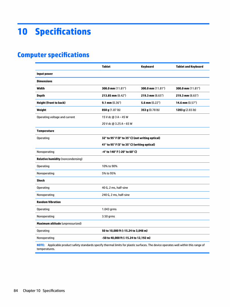
10 Specifications
Computer specifications
Tablet Keyboard Tablet and Keyboard
Input power
Dimensions
Width 300.0 mm (11.81") 300.0 mm (11.81") 300.0 mm (11.81")
Depth 213.85 mm (8.42") 219.3 mm (8.65") 219.3 mm (8.65")
Height (front to back) 9.1 mm (0.36") 5.6 mm (0.22”) 14.6 mm (0.57”)
Weight 850 g (1.87 lb) 353 g (0.78 lb) 1203 g (2.65 lb)
Operating voltage and current 15 V dc @ 3 A – 45 W
20 V dc @ 3.25 A – 65 W
Temperature
Operating 32° to 95° F (0° to 35° C) (not writing optical)
41° to 95° F (5° to 35° C) (writing optical)
Nonoperating -4° to 140° F (-20° to 60° C)
Relative humidity (noncondensing)
Operating 10% to 90%
Nonoperating 5% to 95%
Shock
Operating 40 G, 2 ms, half-sine
Nonoperating 240 G, 2 ms, half-sine
Random Vibration
Operating 1.043 grms
Nonoperating 3.50 grms
Maximum altitude (unpressurized)
Operating 50 to 10,000 ft (-15.24 to 3,048 m)
Nonoperating -50 to 40,000 ft (-15.24 to 12,192 m)
NOTE: Applicable product safety standards specify thermal limits for plastic surfaces. The device operates well within this range of temperatures.
84 Chapter 10 Specifications
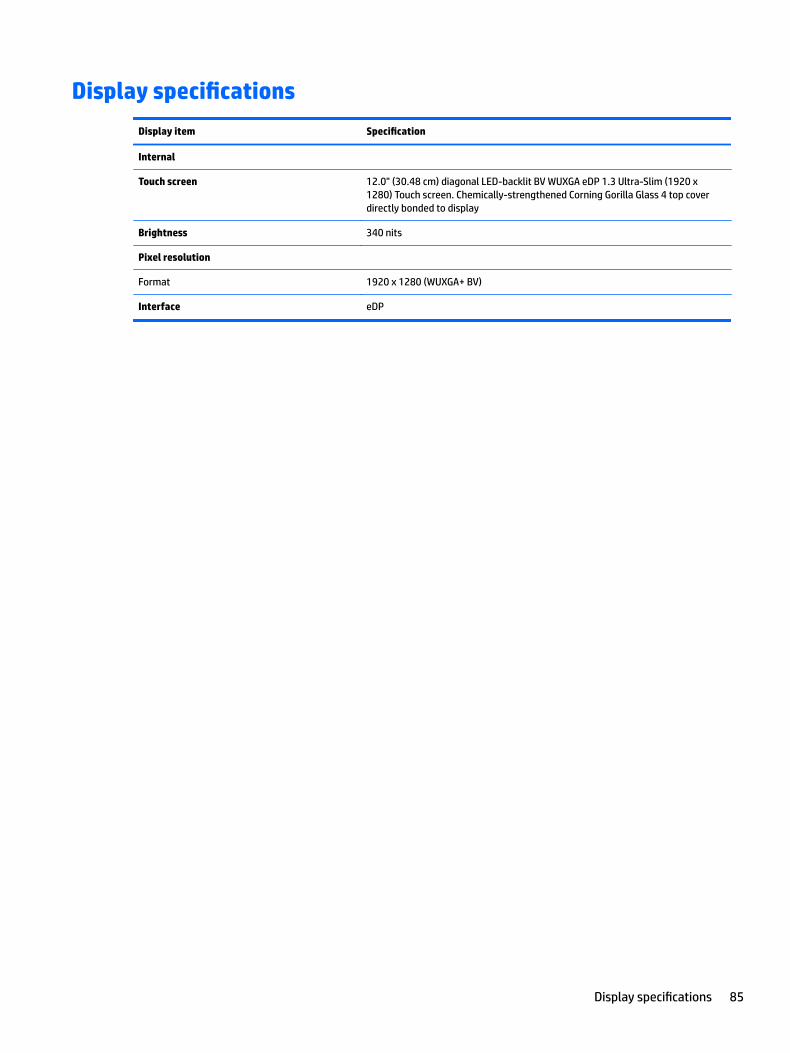
Display specifications
Display item Specification
Internal
Touch screen 12.0" (30.48 cm) diagonal LED-backlit BV WUXGA eDP 1.3 Ultra-Slim (1920 x 1280) Touch screen. Chemically-strengthened Corning Gorilla Glass 4 top cover directly bonded to display
Brightness 340 nits
Pixel resolution
Format 1920 x 1280 (WUXGA+ BV)
Interface eDP
Display specifications 85

11 Power cord set requirements
The wide-range input feature of the computer permits it to operate from any line voltage from 100 to 120 V ac, or from 220 to 240 V ac.
The 3-conductor power cord set included with the computer meets the requirements for use in the country or region where the equipment is purchased.
Power cord sets for use in other countries or regions must meet the requirements of the country and region where the computer is used.
Requirements for all countriesThe following requirements are applicable to all countries and regions:
● The length of the power cord set must be at least 1.0 m (3.3 ft) and no more than 2.0 m (6.5 ft).
● All power cord sets must be approved by an acceptable accredited agency responsible for evaluation in the country or region where the power cord set will be used.
● The power cord sets must have a minimum current capacity of 10 A and a nominal voltage rating of 125 or 250 V ac, as required by the power system of each country or region.
● The appliance coupler must meet the mechanical configuration of an EN 60 320/IEC 320 Standard Sheet C13 connector for mating with the appliance inlet on the back of the computer.
86 Chapter 11 Power cord set requirements

Requirements for specific countries and regions
Country/region Accredited agency Applicable note number
Argentina IRAM 1
Australia SAA 1
Austria OVE 1
Belgium CEBEC 1
Brazil ABNT 1
Canada CSA 2
Chile IMQ 1
Denmark DEMKO 1
Finland FIMKO 1
France UTE 1
Germany VDE 1
India ISI 1
Israel SII 1
Italy IMQ 1
Japan JIS 3
The Netherlands KEMA 1
New Zealand SANZ 1
Norway NEMKO 1
The People's Republic of China CCC 4
Saudi Arabia SASO 7
Singapore PSB 1
South Africa SABS 1
South Korea KTL 5
Sweden SEMKO 1
Switzerland SEV 1
Taiwan BSMI 6
Thailand TISI 1
The United Kingdom ASTA 1
The United States UL 2
1. The flexible cord must be Type HO5VV-F, 3-conductor, 0.75 mm² conductor size. Power cord set fittings (appliance coupler and wall plug) must bear the certification mark of the agency responsible for evaluation in the country or region where it will be used.
2. The flexible cord must be Type SVT/SJT or equivalent, No. 18 AWG, 3-conductor. The wall plug must be a two-pole grounding type with a NEMA 5-15P (15 A, 125 V ac) or NEMA 6-15P (15 A, 250 V ac) configuration. CSA or C-UL mark. UL file number must be on each element.
Requirements for specific countries and regions 87

Country/region Accredited agency Applicable note number
3. The appliance coupler, flexible cord, and wall plug must bear a “T” mark and registration number in accordance with the Japanese Dentori Law. The flexible cord must be Type VCTF, 3-conductor, 0.75 mm² or 1.25 mm² conductor size. The wall plug must be a two-pole grounding type with a Japanese Industrial Standard C8303 (7 A, 125 V ac) configuration.
4. The flexible cord must be Type RVV, 3-conductor, 0.75 mm² conductor size. Power cord set fittings (appliance coupler and wall plug) must bear the CCC certification mark.
5. The flexible cord must be Type H05VV-F 3-conductor, 0.75 mm² conductor size. KTL logo and individual approval number must be on each element. Corset approval number and logo must be printed on a flag label.
6. The flexible cord must be Type HVCTF 3-conductor, 1.25 mm² conductor size. Power cord set fittings (appliance coupler, cable, and wall plug) must bear the BSMI certification mark.
7. For 127 V ac, the flexible cord must be Type SVT or SJT 3-conductor, 18 AWG, with plug NEMA 5-15P (15 A, 125 V ac), with UL and CSA or C-UL marks. For 240 V ac, the flexible cord must be Type H05VV-F 3-conductor, 0.75 mm² or 1.00 mm2 conductor size, with plug BS 1363/A with BSI or ASTA marks.
88 Chapter 11 Power cord set requirements

12 Statement of memory volatility
The purpose of this chapter is to provide general information regarding nonvolatile memory in HP Business computers. This chapter also provides general instructions for restoring nonvolatile memory that can contain personal data after the system has been powered off and the hard drive has been removed.
HP Business computer products that use Intel®-based or AMD®-based system boards contain volatile DDR memory. The amount of nonvolatile memory present in the system depends upon the system configuration. Intel-based and AMD-based system boards contain nonvolatile memory subcomponents as originally shipped from HP, assuming that no subsequent modifications have been made to the system and assuming that no applications, features, or functionality have been added to or installed on the system.
Following system shutdown and removal of all power sources from an HP Business computer system, personal data can remain on volatile system memory (DIMMs) for a finite period of time and will also remain in nonvolatile memory. Use the steps below to remove personal data from the computer, including the nonvolatile memory found in Intel-based and AMD-based system boards.
NOTE: If your tablet has a keyboard base, connect to the keyboard base before beginning steps in this chapter.
1. Follow steps (a) through (l) below to restore the nonvolatile memory that can contain personal data. Restoring or reprogramming nonvolatile memory that does not store personal data is neither necessary nor recommended.
a.● Computers or tablets with keyboards:
▲ Turn on or restart the computer, and when the HP logo appears, press f10 to enter Computer Setup.
● Computers or tablets without keyboards:
▲ Turn off the computer. Press the power button, quickly press the volume down button until the Startup menu is displayed, and then tap f10 to enter Computer Setup.
NOTE: If the system has a BIOS administrator password, enter the password at the prompt.
b. Select Main, select Apply Factory Defaults and Exit, and then select Yes to load defaults.
The computer will reboot.
c. During the reboot, press esc (for tablets without keyboards press the volume down button) while the “Press the ESC key for Startup Menu” message is displayed at the bottom of the screen.
NOTE: If the system has a BIOS administrator password, enter the password at the prompt.
d. Select the Security menu, select Restore Security Settings to Factory Defaults, and then select Yes to restore security level defaults.
The computer will reboot.
e. During the reboot, press esc (for tablets without keyboards press the volume down button) while the “Press the ESC key for Startup Menu” message is displayed at the bottom of the screen.
NOTE: If the system has a BIOS administrator password, enter the password at the prompt.
89

f. If an asset or ownership tag is set, select the Security menu and scroll down to the Utilities menu. Select System IDs, and then select Asset Tracking Number. Clear the tag, and then make the selection to return to the prior menu.
g. If a DriveLock password is set, select the Security menu, and scroll down to Hard Drive Utilities under the Utilities menu. Select Hard Drive Utilities, select DriveLock, then uncheck the checkbox for DriveLock password on restart. Select OK to proceed.
h. Select the Main menu, and then select Reset BIOS Security to factory default. Click Yes at the warning message.
The computer will reboot.
i. During the reboot, press esc (for tablets without keyboards press the volume down button) while the “Press the ESC key for Startup Menu” message is displayed at the bottom of the screen.
NOTE: If the system has a BIOS administrator password, enter the password at the prompt.
j. Select the Main menu, select Apply Factory Defaults and Exit, select Yes to save changes and exit, and then select Shutdown.
k. Reboot the system. If the system has a Trusted Platform Module (TPM) and/or fingerprint reader, one or two prompts will appear—one to clear the TPM and the other to Reset Fingerprint Sensor; press F1 to accept or F2 to reject (for tablets without keyboards select Accept or Reject on the screen).
l. Remove all power and system batteries for at least 24 hours.
2. Complete one of the following:
● Remove and retain the storage drive.
– or –
● Clear the drive contents by using a third party utility designed to erase data from an SSD.
– or –
● Clear the contents of the drive by using the following BIOS Setup Secure Erase command option steps:
IMPORTANT: If you clear data using Secure Erase, it cannot be recovered.
a.● Computers or tablets with keyboards:
▲ Turn on or restart the computer, and when the HP logo appears, press f10 to enter Computer Setup.
● Computers or tablets without keyboards:
▲ Turn off the computer. Press the power button, quickly press the volume down button until the Startup menu is displayed, and then tap f10 to enter Computer Setup.
b. Select the Security menu and scroll down to the Utilities menu.
c. Select Hard Drive Utilities.
d. Under Utilities, select Secure Erase, select the hard drive storing the data you want to clear, and then follow the on-screen instructions to continue.
90 Chapter 12 Statement of memory volatility

Nonvolatile memory usage
Nonvolatile Memory Type Amount (Size)
Does this memory store customer data?
Does this memory retain data when power is removed?
What is the purpose of this memory?
How is data input into this memory?
How is this memory write-protected?
HP Sure Start flash (select models only)
8 MBytes No Yes Provides protected backup of critical System BIOS code, EC firmware, and critical computer configuration data for select platforms that support HP Sure Start.
For more information, see Using HP Sure Start (select models only) on page 94.
Data cannot be written to this device via the host processor. The content is managed solely by the HP Sure Start Embedded Controller.
This memory is protected by the HP Sure Start Embedded Controller.
Real Time Clock (RTC) battery backed-up CMOS configuration memory
256 Bytes No Yes Stores system date and time and noncritical data.
RTC battery backed-up CMOS is programmed using the Computer Setup (BIOS), or changing the Microsoft Windows date & time.
This memory is not write-protected.
Controller (NIC) EEPROM
64 KBytes (not customer accessible)
No Yes Stores NIC configuration and NIC firmware.
NIC EEPROM is programmed using a utility from the NIC vendor that can be run from DOS.
A utility is required to write data to this memory and is available from the NIC vendor. Writing data to this ROM in an inappropriate manner will render the NIC non-functional.
DIMM Serial Presence Detect (SPD) configuration data
256 Bytes per memory module, 128 Bytes programmable (not customer accessible)
No Yes Stores memory module information.
DIMM SPD is programmed by the memory vendor.
Data cannot be written to this memory when the module is installed in a computer. The specific write-protection method varies by memory vendor.
System BIOS 9 MBytes Yes Yes Stores system BIOS code and computer configuration data.
System BIOS code is programmed at the factory. Code is updated when the system BIOS is updated. Configuration data and settings are input using the Computer Setup (BIOS) or a custom utility.
NOTE: Writing data to this ROM in an inappropriate manner can render the computer non-functional.
A utility is required for writing data to this memory and is available on the HP website; go to http://www.hp.com/support. Select Find your
Nonvolatile memory usage 91

Nonvolatile Memory Type Amount (Size)
Does this memory store customer data?
Does this memory retain data when power is removed?
What is the purpose of this memory?
How is data input into this memory?
How is this memory write-protected?
product, and then follow the on-screen instructions.
Intel Management Engine Firmware (present only in select Elite or Z models. For more information, go to http://www.hp.com/support. Select Find your product, and then follow the on-screen instructions.)
1.5 MBytes or 7 MBytes
Yes Yes Stores Management Engine Code, Settings, Provisioning Data and iAMT third-party data store.
Management Engine Code is programmed at the factory. Code is updated via Intel secure firmware update utility. Unique Provisioning Data can be entered at the factory or by an administrator using the Management Engine (MEBx) setup utility. The third party data store contents can be populated by a remote management console or local applications that have been registered by an administrator to have access to the space.
The Intel chipset is configured to enforce hardware protection to block all direct read/write access to this area. An Intel utility is required for updating the firmware. Only firmware updates digitally signed by Intel can be applied using this utility.
Bluetooth flash (select products only)
2 Mbit No Yes Stores Bluetooth configuration and firmware.
Bluetooth flash is programmed at the factory. Tools for writing data to this memory are not publicly available but can be obtained from the silicon vendor.
A utility is required for writing data to this memory and is made available through newer versions of the driver whenever the flash requires an upgrade.
802.11 WLAN EEPROM
4 Kbit to 8 Kbit No Yes Stores configuration and calibration data.
802.11 WLAN EEPROM is programmed at the factory. Tools for writing data to this memory are not made public.
A utility is required for writing data to this memory and is typically not made available to the public unless a firmware upgrade is necessary to address a unique issue.
Webcam (select products only)
64 Kbit No Yes Stores webcam configuration and firmware.
Webcam memory is programmed using a utility from the device manufacturer that can be run from Windows.
A utility is required for writing data to this memory and is typically not made available to the public unless a firmware upgrade is necessary to address a unique issue.
Fingerprint reader (select products only)
512 KByte flash Yes Yes Stores fingerprint templates.
Fingerprint reader memory is programmed by user enrollment in HP ProtectTools Security Manager.
Only a digitally signed application can make the call to write to the flash.
92 Chapter 12 Statement of memory volatility

Questions and answers1. How can the BIOS settings be restored (returned to factory settings)?
IMPORTANT: Restore defaults does not securely erase any data on your hard drive. See question and answer 6 for steps to securely erase data.
Restore defaults does not reset the Custom Secure Boot keys. See question and answer 7 for information about resetting the keys.
a. ○ Computers or tablets with keyboards:
▲ Turn on or restart the computer, and when the HP logo appears, press f10 to enter Computer Setup.
○ Computers or tablets without keyboards:
▲ Turn off the computer. Press the power button, quickly press the volume down button until the Startup menu is displayed, and then tap f10 to enter Computer Setup.
NOTE: If the system has a BIOS administrator password, enter the password at the prompt.
b. Select Main, and then select Apply Factory Defaults and Exit.
c. Follow the on-screen instructions.
d. Select Main, select Save Changes and Exit, and then follow the on-screen instructions.
2. What is a UEFI BIOS, and how is it different from a legacy BIOS?
The Unified Extensible Firmware Interface (UEFI) BIOS is an industry-standard software interface between the platform firmware and an operating system (OS). It is a replacement for the older BIOS architecture, but supports much of the legacy BIOS functionality.
Like the legacy BIOS, the UEFI BIOS provides an interface to display the system information and configuration settings and to change the configuration of your computer before an OS is loaded. BIOS provides a secure run-time environment that supports a Graphic User Interface (GUI). In this environment, you can use either a pointing device (Touchscreen, TouchPad, pointing stick, or USB mouse) or the keyboard to navigate and make menu and configuration selections. The UEFI BIOS also contains basic system diagnostics.
The UEFI BIOS provides functionality beyond that of the legacy BIOS. In addition, the UEFI BIOS works to initialize the computer’s hardware before loading and executing the OS; the run-time environment allows the loading and execution of software programs from storage devices to provide more functionality, such as advanced hardware diagnostics (with the ability to display more detailed system information) and advanced firmware management and recovery software.
HP has provided options in Computer Setup (BIOS) to allow you to run in legacy BIOS, if required by the operating system. Examples of this requirement would be if you upgrade or downgrade the OS.
3. Where does the UEFI BIOS reside?
The UEFI BIOS resides on a flash memory chip. A utility is required to write to the chip.
4. What kind of configuration data is stored on the DIMM Serial Presence Detect (SPD) memory module? How would this data be written?
The DIMM SPD memory contains information about the memory module, such as size, serial number, data width, speed/timing, voltage, and thermal information. This information is written by the module manufacturer and stored on an EEPROM. This EEPROM cannot be written to when the memory module is installed in a computer. Third-party tools do exist that can write to the EEPROM when the memory module is not installed in a computer. Various third-party tools are available to read SPD memory.
Questions and answers 93
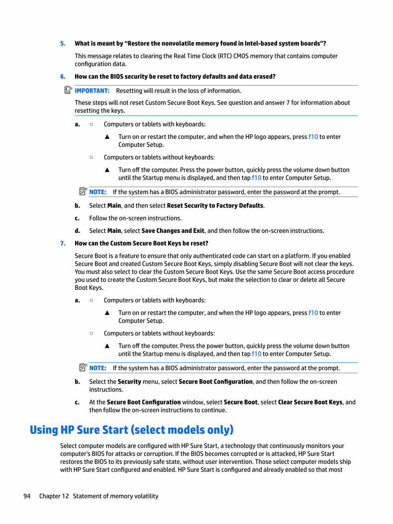
5. What is meant by “Restore the nonvolatile memory found in Intel-based system boards”?
This message relates to clearing the Real Time Clock (RTC) CMOS memory that contains computer configuration data.
6. How can the BIOS security be reset to factory defaults and data erased?
IMPORTANT: Resetting will result in the loss of information.
These steps will not reset Custom Secure Boot Keys. See question and answer 7 for information about resetting the keys.
a. ○ Computers or tablets with keyboards:
▲ Turn on or restart the computer, and when the HP logo appears, press f10 to enter Computer Setup.
○ Computers or tablets without keyboards:
▲ Turn off the computer. Press the power button, quickly press the volume down button until the Startup menu is displayed, and then tap f10 to enter Computer Setup.
NOTE: If the system has a BIOS administrator password, enter the password at the prompt.
b. Select Main, and then select Reset Security to Factory Defaults.
c. Follow the on-screen instructions.
d. Select Main, select Save Changes and Exit, and then follow the on-screen instructions.
7. How can the Custom Secure Boot Keys be reset?
Secure Boot is a feature to ensure that only authenticated code can start on a platform. If you enabled Secure Boot and created Custom Secure Boot Keys, simply disabling Secure Boot will not clear the keys. You must also select to clear the Custom Secure Boot Keys. Use the same Secure Boot access procedure you used to create the Custom Secure Boot Keys, but make the selection to clear or delete all Secure Boot Keys.
a. ○ Computers or tablets with keyboards:
▲ Turn on or restart the computer, and when the HP logo appears, press f10 to enter Computer Setup.
○ Computers or tablets without keyboards:
▲ Turn off the computer. Press the power button, quickly press the volume down button until the Startup menu is displayed, and then tap f10 to enter Computer Setup.
NOTE: If the system has a BIOS administrator password, enter the password at the prompt.
b. Select the Security menu, select Secure Boot Configuration, and then follow the on-screen instructions.
c. At the Secure Boot Configuration window, select Secure Boot, select Clear Secure Boot Keys, and then follow the on-screen instructions to continue.
Using HP Sure Start (select models only)Select computer models are configured with HP Sure Start, a technology that continuously monitors your computer's BIOS for attacks or corruption. If the BIOS becomes corrupted or is attacked, HP Sure Start restores the BIOS to its previously safe state, without user intervention. Those select computer models ship with HP Sure Start configured and enabled. HP Sure Start is configured and already enabled so that most
94 Chapter 12 Statement of memory volatility

users can use the HP Sure Start default configuration. The default configuration can be customized by advanced users.
To access the latest documentation on HP Sure Start, go to http://www.hp.com/support. Select Find your product, and then follow the on-screen instructions.
Using HP Sure Start (select models only) 95

13 Recycling
When a non-rechargeable or rechargeable battery has reached the end of its useful life, do not dispose of the battery in general household waste. Follow the local laws and regulations in your area for battery disposal.
HP encourages customers to recycle used electronic hardware, HP original print cartridges, and rechargeable batteries.
96 Chapter 13 Recycling
Index
AAC adapter, spare part numbers
spare part number 23answer calls 19antennas 70
spare part number 22spare part numbers 70
audio, product description 2audio-out (headphone)/audio-in
(microphone) combo jack, identifying 6
Bbackups 72battery 49
spare part numbers 23, 35, 49battery light 5battery, disconnecting 35BIOS
determining version 79downloading an update 79updating 79
Bluetooth label 20boot order
changing 75bottom 20button
volume down 7volume up 7
buttonsleft TouchPad 14power 6right TouchPad 14
Ccall answer light 15call end light 15camera flash, identifying 11caps lock light, identifying 15chipset, product description 1components
bottom 10front 8keyboard 13left side 6
rear 11right side 5top 9
computer major components 21Computer Setup
navigating and selecting 78restoring factory settings 78
computer specifications 84
Ddisplay
specifications 85display cable kit
spare part numbers 23, 45display panel 45
product description 1docking connector, identifying 10docking station
product description 3
Eembedded numeric keypad,
identifying 17end calls 19esc key, identifying 17Ethernet, product description 2
Ffingerprint board
spare part numbers 59fingerprint reader
spare part number 22fingerprint reader board 59fingerprint reader, identifying 11fn key, identifying 17fn lock light, identifying 16Front webcam 59front webcam 55
spare part number 22, 59
GGPS module 41graphics, product description 1
HHall effects sensor board 51
spare part numbers 23, 51hard drive
product description 1hinges
spare part number 22spare part numbers 36
hot keysanswering calls 19break an operation 19calendar display 18ending calls 19insert 19microphone mute 18screen shot 19scroll lock 19sharing or presenting 19using 18volume decrease 18volume increase 18
HP PC Hardware Diagnostics (UEFI)Failure ID code 82using 82
HP Recovery Managercorrecting boot problems 75starting 75
HP Recovery mediacreating 72recovery 75
HP Recovery partitionrecovery 75removing 76
HP Sure Start 94
Iinsert 19integrated camera flash,
identifying 11integrated webcam light,
identifying 8internal microphones, identifying 9
Index 97

Jjacks
audio-out (headphone)/audio-in (microphone) combo 6
Kkeyboard
components 13connecting 13product description 3removal 31removing 14spare part numbers 23, 31
keypadembedded numeric 17
keysesc 17fn 17Windows key 17
kickstand 36spare part number 22spare part numbers 36
kickstand tabs, identifying 11kickstand, identifying 11
Llabels
Bluetooth 20regulatory 20serial number 19service 19wireless certification 20WLAN 20
lightsbattery 5call answer 15call end 15caps lock 15fn lock 16microphone mute 15num lock 15sharing 15webcam 8, 11wireless 15
locating informationhardware 5software 5
Mmemory
nonvolatile 89volatile 89
memory card reader, identifying 7memory module
product description 1micro SIM card tray
spare part numbers 32Microphone board 58microphone board 55
spare part number 22, 58microphone mute key, identifying
18microphone mute light, identifying
15microSD memory card tray
removing 33spare part numbers 33
middle frame 71spare part number 22spare part numbers 71
minimized image recovery 75minimized image, creating 74model name 1
Nnear field communication antenna,
identifying 11NFC antenna, identifying 11NFC module 53
spare part numbers 53NFC module and antenna
spare part number 22NFC tapping area, identifying 11nonvolatile memory 89num lock light 15
Ooperating system, product
description 4original system recovery 74
Ppanel
spare part numbers 23, 45pen
spare part number 23pen lanyard slot, identifying 7plastics kit
spare part number 23, 59
POGO connector 55, 58spare part number 58spare part numbers 23
POGO pin connector, identifying 10pointing device, product
description 3ports
product description 3USB 3.x charging 6USB Type-C power connector and
charging 5power button 66
spare part number 22power button, identifying 6power cord
requirements for all countries86
requirements for specific countries and regions 87
set requirements 86spare part number 23
power cord with duck headspare part number 24
power requirements, product description 3
processorproduct description 1
product descriptionaudio 2camera 2chipset 1display panel 1docking station 3Ethernet 2external media cards 3graphics 1keyboard 3memory module 1microphone 2operating system 4pointing device 3ports 3power requirements 3processors 1product name 1security 3sensors 3serviceability 4storage 1wireless 2
98 Index

product name 1product name and number,
computer 19
Rrear cover
spare part number 22spare part numbers 34
rear cover, removing 34rear webcam and flash
spare part number 22recover
options 74recovery
discs 73, 75HP Recovery Manager 74media 75starting 75supported discs 73system 74USB flash drive 75using HP Recovery media 73
recovery mediacreating 72creating using HP Recovery
Manager 73recovery partition
removing 76regulatory information
regulatory label 20wireless certification labels 20
removal/replacementprocedures 30, 40
removing personal data from volatile system memory 89
Sscreen shot 19screw kit
spare part number 24scroll lock 19SD card tray
spare part number 22security cable slot, identifying 7security, product description 3sensors
product description 3serial number 19serial number, computer 19service labels, locating 19
serviceability, product description 4setup utility
navigating and selecting 78restoring factory settings 78
sharing light 15sharing or presenting 19SIM card
inserting 6removing 6
SIM card slot, identifying 6SIM card tray
spare part number 22slots
security cable 7SIM card 6smart card 9
smart cardslot 9
Smart card reader board and bracketspare part numbers 22, 61
smart card reader board and bracket 61
speakers 68spare part number 22spare part numbers 68
speakers, identifying 9special keys 17specifications
computer 84display 85
SSD 38spare part number 22spare part numbers 38
supported discs, recovery 73Sure Start
using 81system board 55
spare part numbers 22, 55system memory, removing personal
data from volatile 89system recovery 74system restore point
creating 73system restore point, creating 72
TTouchPad
buttons 14TouchPad zone
identifying 14
TPM settings 80traveling with the computer 20
UUSB 3.x charging port, identifying 6USB Type-C bracket 55USB type-C bracket
spare part number 22spare part numbers 64, 66
USB Type-C power connector and charging port, identifying 5
Vvolume button 64
spare part number 22volume button, identifying 7
Wwebcam 8
identifying 11rear 43spare part numbers 43
webcam light, identifying 8webcam, identifying 8Windows
system restore point 72, 73Windows key, identifying 17Windows tools
using 73wireless antennas, identifying 8wireless certification label 20wireless light 15wireless, product description 2WLAN antennas, identifying 8WLAN device 20WLAN label 20WWAN antennas, identifying 8WWAN module 41
spare part number 22spare part numbers 41
Index 99