hp proliant dl140 generation 2 and hp proliant dl145 ... · pdf fileusing secure shell ......
TRANSCRIPT

HP ProLiant DL140 Generation 2 and HP ProLiant DL145 Generation 2 Lights-Out 100i Remote Management Processor User Guide
December 2005 (Third Edition) Part Number 390153-003

© Copyright 2005 Hewlett-Packard Development Company, L.P.
The information contained herein is subject to change without notice. The only warranties for HP products and services are set forth in the express warranty statements accompanying such products and services. Nothing herein should be construed as constituting an additional warranty. HP shall not be liable for technical or editorial errors or omissions contained herein.
Confidential computer software. Valid license from HP required for possession, use or copying. Consistent with FAR 12.211 and 12.212, Commercial Computer Software, Computer Software Documentation, and Technical Data for Commercial Items are licensed to the U.S. Government under vendor’s standard commercial license.
Microsoft and Windows are U.S. registered trademarks of Microsoft Corporation. Linux is a U.S. registered trademark of Linus Torvalds.
December 2005 (Third Edition) Part Number 390153-003
Audience assumptions This document is for the person who installs, administers, and troubleshoots servers and storage systems. HP assumes you are qualified in the servicing of computer equipment and trained in recognizing hazards in products with hazardous energy levels.
Contents 3
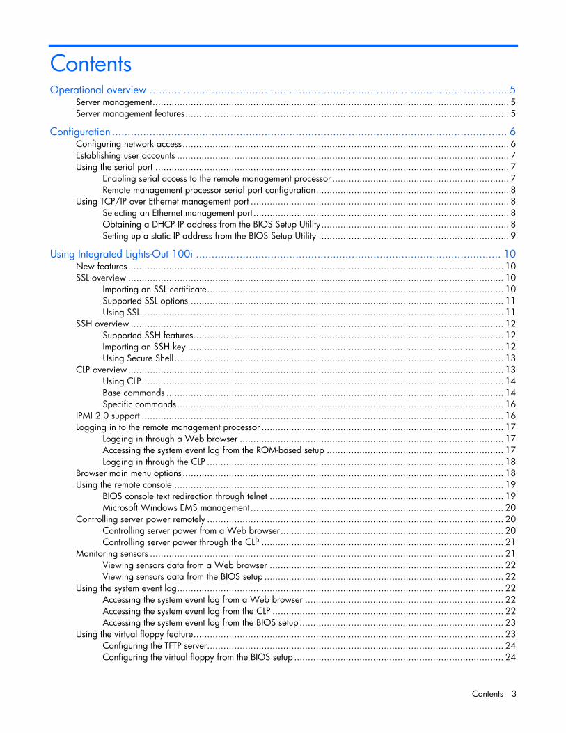
Contents Operational overview ................................................................................................................... 5
Server management................................................................................................................................... 5 Server management features....................................................................................................................... 5
Configuration ............................................................................................................................... 6 Configuring network access........................................................................................................................ 6 Establishing user accounts .......................................................................................................................... 7 Using the serial port .................................................................................................................................. 7
Enabling serial access to the remote management processor ................................................................. 7 Remote management processor serial port configuration....................................................................... 8
Using TCP/IP over Ethernet management port ............................................................................................... 8 Selecting an Ethernet management port .............................................................................................. 8 Obtaining a DHCP IP address from the BIOS Setup Utility..................................................................... 8 Setting up a static IP address from the BIOS Setup Utility ...................................................................... 9
Using Integrated Lights-Out 100i .................................................................................................. 10 New features .......................................................................................................................................... 10 SSL overview .......................................................................................................................................... 10
Importing an SSL certificate............................................................................................................. 10 Supported SSL options ................................................................................................................... 11 Using SSL ..................................................................................................................................... 11
SSH overview ......................................................................................................................................... 12 Supported SSH features.................................................................................................................. 12 Importing an SSH key .................................................................................................................... 12 Using Secure Shell ......................................................................................................................... 13
CLP overview.......................................................................................................................................... 13 Using CLP..................................................................................................................................... 14 Base commands ............................................................................................................................ 14 Specific commands........................................................................................................................ 16
IPMI 2.0 support ..................................................................................................................................... 16 Logging in to the remote management processor ......................................................................................... 17
Logging in through a Web browser ................................................................................................. 17 Accessing the system event log from the ROM-based setup ................................................................. 17 Logging in through the CLP ............................................................................................................. 18
Browser main menu options...................................................................................................................... 18 Using the remote console ......................................................................................................................... 19
BIOS console text redirection through telnet ...................................................................................... 19 Microsoft Windows EMS management ............................................................................................. 20
Controlling server power remotely ............................................................................................................. 20 Controlling server power from a Web browser.................................................................................. 20 Controlling server power through the CLP ......................................................................................... 21
Monitoring sensors .................................................................................................................................. 21 Viewing sensors data from a Web browser ...................................................................................... 22 Viewing sensors data from the BIOS setup ........................................................................................ 22
Using the system event log........................................................................................................................ 22 Accessing the system event log from a Web browser ......................................................................... 22 Accessing the system event log from the CLP ..................................................................................... 22 Accessing the system event log from the BIOS setup ........................................................................... 23
Using the virtual floppy feature.................................................................................................................. 23 Configuring the TFTP server............................................................................................................. 24 Configuring the virtual floppy from the BIOS setup ............................................................................. 24

Contents 4
Configuring virtual floppy from a Web browser................................................................................. 24 Configuring virtual floppy from the CLP ............................................................................................ 25 Rebooting the server ...................................................................................................................... 25
Hardware Inventory page ........................................................................................................................ 26 User administration.................................................................................................................................. 26
Changing the password through a Web browser .............................................................................. 26 Changing the password through the CLP .......................................................................................... 27
Additional network settings....................................................................................................................... 27 Configuring network settings using a Web browser ........................................................................... 28 Configuring network settings using the CLP ....................................................................................... 28
IPMI Platform Event Filtering configuration pages......................................................................................... 28 IPMI Platform Event Trap Configuration page .............................................................................................. 30
Acronyms and abbreviations........................................................................................................ 31
Index......................................................................................................................................... 33
Operational overview 5
Operational overview
In this section Server management.................................................................................................................................. 5 Server management features...................................................................................................................... 5
Server management The HP ProLiant DL140 Generation 2 or HP ProLiant DL145 Generation 2 Lights-Out 100i Remote Management Processor delivers basic remote control of vital server resources and supports IPMI 2.0. Throughout this document, you will also see the term "BMC," which is synonymous with remote management processor.
The ProLiant DL140 G2 or ProLiant DL145 G2 Lights-Out 100i Remote Management Processor provides system administrators with access to the server at any time, even before an operating system is installed on the server. This remote management processor provides a text mode console redirection, IPMI CLP, and browser access to many of the same IPMI functions. You can access the remote management processor and the management features of the HP ProLiant DL140 G2 or ProLiant DL145 G2 Server through a dedicated Ethernet port over a TCP/IP management port or the integrated serial port.
Server management features With the ProLiant DL140 G2 or ProLiant DL145 G2 Lights-Out 100i Remote Management Processor, you can: • Switch between console redirection and the command line using either the dedicated management
or serial port • Communicate securely using SSL and SSH • Remotely power on and off the server • Perform warm or cold server reboots • Reboot the server to a virtual floppy • Remotely monitor server state voltage, fan speed, and system state (S0 or S5) • Access the System Event Log • Configure TCP/IP settings for the NIC • Change user password • Access the BMC and server controls using a standard browser or new industry standard SMASH CLP
command line interface • Access command line help • Manage the server with IPMI 2.0 compliant applications
Configuration 6
Configuration
In this section Configuring network access....................................................................................................................... 6 Establishing user accounts ......................................................................................................................... 7 Using the serial port ................................................................................................................................. 7 Using TCP/IP over Ethernet management port.............................................................................................. 8
Configuring network access The server is connected to the network using a standard Ethernet cable. Through this connection, you can access the remote management CLP, verify POST remotely, and access the BIOS setup utility remotely.
To configure network access: 1. Connect a standard Ethernet cable between the onboard NIC on the server rear panel and a
network jack. By default, the remote management card has DHCP enabled and will automatically negotiate an IP address. (The ProLiant DL140 G2 or ProLiant DL145 G2 system also provides the ability to set up a static IP address through the BIOS setup menu. Refer to the following "To set up a static IP address" procedure.)
2. Obtain the DHCP IP address by using one of the following methods: • Look at the DHCP clients table • Read the IP address from BIOS setup menu (Press the F10 key during POST) under
Advanced/IPMI/LAN Setting. 3. On the target server, press the F10 key during POST to enter BIOS setup. 4. In the BIOS Setup utility, press the right arrow (→) key to navigate to the Advanced menu. 5. Press the down arrow (↓) key to scroll to IPMI. Press the Enter key. 6. Press the down arrow (↓) key to scroll to the LAN Settings submenu. Press the Enter key. 7. Press the down arrow (↓) key to scroll to the following settings, and set the parameters as needed
(the following example shows configuring for remote management processor access using telnet and a Web page): • BMC Telnet Service: [Enabled] • BMC Ping Response: [Enabled] • BMC HTTP Server: [Enabled]
8. Using the DHCP IP address, use telnet to log into the remote management CLP, or use a Web browser to access the HTML interface.
To set up a static IP address: 1. On the target server, press the F10 key during POST to enter BIOS setup. 2. In the BIOS Setup utility, press the right arrow (→) key to navigate to the Advanced menu. 3. Press the down arrow (↓) key to scroll to IPMI. Press the Enter key. 4. Press the down arrow (↓) key to scroll to the LAN Settings submenu. Press the Enter key.
Configuration 7
5. Set the IP Address Assignment to STATIC. This setting enables you to modify a static IP address through the BIOS setup menu.
6. Press the down arrow (↓) key to scroll down and enter a valid IP address, subnet mask, and gateway address (press the Tab key to move between address fields).
7. Press the down arrow (↓) key to scroll to the following settings, and set the parameters as needed (the following example shows configuring for remote management processor access using telnet and a Web page): • BMC Telnet Service: [Enabled] • BMC Ping Response: [Enabled] • BMC HTTP Server: [Enabled]
8. Press the F10 key to save and exit.
Establishing user accounts The remote management card supports an administrator and an operator account.
The default account is Administrator, which enables the user to execute the full set of CLP commands and change management processor configuration. The default user name is admin, and the default password is admin.
The operator account enables the user to execute common commands and functions but restricts access to specific functions, such as adding and changing user account information and changing the configuration of the management processor. HP recommends logging in with the operator account to perform common functions. The default user name is Operator, and the default password is Operator.
For more information on how to log in to the remote management card, refer to the "Logging in to the remote management processor (on page 17)" section.
Using the serial port The server serial port provides basic serial port functionality and also serves as an interface to the remote management processor. You can configure the system serial port for exclusive use with BMC.
CAUTION: After the port has been enabled for use with BMC, legacy serial devices might not function correctly if attached to the serial port.
You must also configure the remote management processor serial port hardware parameters to work with your respective serial port communications software. Remote management processor serial port configuration is controlled with the BIOS Setup Utility.
Enabling serial access to the remote management processor 1. Power on the server by pressing the power on/off button on the front panel. 2. When POST shows the message ROM-Based Setup, press the F10 key. If the server has an
administrator password configured, the system prompts you to enter the password. If the server does not have a password configured, the main screen of the BIOS Setup Utility appears.
3. Press the right arrow (→) key to navigate to the Advanced menu. 4. Press the down arrow key (↓) to scroll to the IO Device Configuration menu. Press the Enter key. 5. Press the down arrow key (↓) to scroll to the Serial Port menu. Press the Enter key to toggle between
SIO COM Port and BMC COM Port. 6. Select BMC COM Port.
Configuration 8
Remote management processor serial port configuration 1. Power on the server by pressing the power on/off button on the front panel. 2. When POST shows the message ROM-Based Setup, press the F10 key. If the server has an
administrator password configured, the system prompts you to enter the password. If the server does not have a password configured, the main screen of the BIOS Setup Utility appears.
3. Press the right arrow (→) key to navigate to the Advanced menu. 4. Press the down arrow (↓) key to scroll to the Console Redirection menu. 5. Press the Enter key to toggle between Enabled and Disabled. Select Enabled. 6. Review the serial port settings, and be sure the settings match the serial port communications
software settings used to connect to the remote management processor. 7. Press the Esc key to return to the previous screen, or press the F10 key to save the changes and exit
Setup.
Using TCP/IP over Ethernet management port The remote management processor LAN port can be accessed from two different Ethernet ports: the dedicated 10\100 LOi00i management port, or through a side-band connection with the second LOM (NIC2).
Selecting an Ethernet management port To select either the LO100i or side-band connection: 1. Power on the server by pressing the power on/off button on the front panel. 2. When POST displays the message ROM-Based Setup, press the F10 key. If the server has an
administrator password configured, the system prompts you to enter the password. If the server does not have a password configured, the main screen of the BIOS Setup Utility appears.
3. Press the right arrow (→) key to navigate to the Advanced menu. 4. Press the down arrow (↓) key to scroll to NIC Option. Press the Enter key to select between the
dedicated or side-band connection. 5. Press the Esc key to return to the previous screen, or press the F10 key to save the changes and exit
Setup.
The dedicated TCP\IP over Ethernet management port, whether dedicated or shared, is a standard Ethernet 10\100Mb interface and is connected to the network using a standard Ethernet cable. Before using the dedicated management port, you must determine the DHCP IP address, set a static IP address, or use the default static IP address.
Obtaining a DHCP IP address from the BIOS Setup Utility 1. By default, the remote management processor has DHCP enabled and automatically negotiates an IP
address. To view the DHCP IP address, run the BIOS setup program or retrieve the DHCP IP address using CLI through the serial port connection.
2. Power on the server by pressing the power on/off button on the front panel. 3. When POST displays the message ROM-Based Setup, press the F10 key. If the server has an
administrator password configured, the system prompts you to enter the password. If the server does not have a password configured, the main screen of the BIOS Setup Utility appears.
4. Press the right arrow (→) key to navigate to the Advanced menu. 5. Press the down arrow (↓) key to scroll to the IPMI menu. Press the Enter key.
Configuration 9
6. Note the DHCP assigned IP address for future reference. 7. Press the Esc key to return to the previous screen, or press the F10 key to save the changes and exit
Setup.
Setting up a static IP address from the BIOS Setup Utility By default, the remote management processor has DHCP enabled and automatically negotiates an IP address. To disable DHCP and enable a static address: 1. Power on the server by pressing the power on/off button on the front panel. 2. When POST displays the message ROM-Based Setup, press the F10 key. If the server has an
administrator password configured, the system prompts you to enter the password. If the server does not have a password configured, the main screen of the BIOS Setup Utility appears.
3. Press the right arrow (→) key to navigate to the Advanced menu. 4. Press the down arrow (↓) key to scroll to the IPMI menu. Press the Enter key. 5. Press the Enter key to toggle between DHCP and Static. Select Static. 6. Press the down arrow (↓) key to scroll to the IP address field. 7. Press the right arrow (→) key to move to first octet. 8. Enter the four octets of the static IP address, pressing the Enter or Tab key to move between each
octet. 9. Enter the subnet mask and gateway addresses as necessary. 10. Note the static IP, subnet mask, and gateway addresses for future reference. 11. Press the Esc key to return to the previous screen, or press the F10 key to save the changes and exit
Setup.
Using Integrated Lights-Out 100i 10
Using Integrated Lights-Out 100i
In this section New features ......................................................................................................................................... 10 SSL overview ......................................................................................................................................... 10 SSH overview ........................................................................................................................................ 12 CLP overview......................................................................................................................................... 13 IPMI 2.0 support .................................................................................................................................... 16 Logging in to the remote management processor........................................................................................ 17 Browser main menu options..................................................................................................................... 18 Using the remote console ........................................................................................................................ 19 Controlling server power remotely............................................................................................................ 20 Monitoring sensors ................................................................................................................................. 21 Using the system event log....................................................................................................................... 22 Using the virtual floppy feature ................................................................................................................ 23 Hardware Inventory page ....................................................................................................................... 26 User administration................................................................................................................................. 26 Additional network settings...................................................................................................................... 27 IPMI Platform Event Filtering configuration pages ....................................................................................... 28 IPMI Platform Event Trap Configuration page............................................................................................. 30
New features • Encrypted browser communication using SSL • Encrypted command line interface communication using SSH • DMTF SMASH CLP support • IPMI 2.0 support
SSL overview The ProLiant DL140 G2 or ProLiant DL145 G2 Lights-Out 100i remote management processor provides strong security for remote management in distributed IT environments by using 128-bit SSL encryption of HTTP data transmitted across the network. SSL encryption ensures that the HTTP information is secure as it travels across the network.
Before using SSL for the first time, perform the one-time setup procedure detailed in the "Importing an SSL certificate (on page 10)" section.
Importing an SSL certificate Before using the new SSL or SSH features of the Lights-Out 100 remote management processor, you must create and install a public key (certificate). The key must be generated using external third-party software, placed on a TFTP server, and uploaded to the Lights-Out 100 remote management processor.
Using Integrated Lights-Out 100i 11
The Lights-Out 100 remote management processor requires a 2048-bit DSA key stored in PEM (Base64 encoded) format to be located on a TFTP server. For example, the following process uses Win32 OpenSSL, downloaded from the Shining Light Productions website (http://www.slproweb.com/products/Win32OpenSSL.html), and the commands issued in a DOS window to generate the certificate. To generate a certificate using Win32 OpenSSL: 1. Download Win32 OpenSSL. 2. Install and set up OpenSSL. 3. Using OpenSSL, generate a DSA parameters file:
openssl dsaparam -out server_dsaparam.pem 2048
4. Generate the DSA private key file, called server_privkey.pem: openssl gendsa -out server_privkey.pem server_dsaparam.pem
5. Generate the DSA certificate (public key) file, called server_cacert.pem: openssl req -new -x509 -key sshkey -out server_cacert.pem -days 1095
6. When prompted for a distinguished name, enter an appropriate domain name for the servers that will receive the certificate.
7. After a certificate has been created and copied to a TFTP server accessible on the same network as the Lights-Out 100 remote management processor, use the CLP interface to log in to the Lights-Out 100 remote management processor as administrator, and issue the command to upload and install the certificate (the following commands can also be found in the /map1 directory): load -source <URI> -oemhpfiletype cer Where: • <URI>is the //tftpserver IP/path/filename to be downloaded. • tftpserver is the URL or IP address of the TFTP server containing the certificate. • filename is the file name of the certificate file.
Supported SSL options The remote management processor supports version SSLv3/TLSv1 of the protocol. The supported algorithms are:
Algorithm Supported version
Symmetric cyphers DES, 3DES, AES
Asymmetrical encryption Diffie-Hellman, DSA
Symmetric modes CBC
Hash algorithms SHA, SHA1
MAC algorithm HMAC-SHA
Certificates X.509v3
Using SSL If you cannot access the login page, you must verify the SSL encryption level of your browser is set to 128 bits. The SSL encryption level within the management processor is set to 128 bits and cannot be changed. The browser and management processor encryption levels must be the same.
Using Integrated Lights-Out 100i 12
SSH overview SSH is a telnet-like program for logging into and for executing commands on a remote machine, which includes security with authentication, encryption, and data integrity features. The ProLiant DL140 G2 or ProLiant DL145 G2 Lights-Out 100i remote management processor can support simultaneous access from two SSH clients. After SSH is connected and authenticated, the command line interface is available.
Before using SSH for the first time, perform the one-time setup procedure detailed in the "Importing an SSH key (on page 12)" section.
The remote management processor supports: • SSH protocol version 2. • PuTTY 0.54, which is a free version of telnet and SSH protocol available for download on the
Internet. When using PuTTY, versions before 0.54 might display two line feeds instead on a single line feed, when the Enter key is pressed. To avoid this issue and for best results, HP recommends using version 0.54 or later.
• OpenSSH, which is a free version of the SSH protocol available for download on the Internet.
NOTE: Logging in to an SSH session could take up to 90 seconds. Depending on the client used, you might not see on-screen activity during this time.
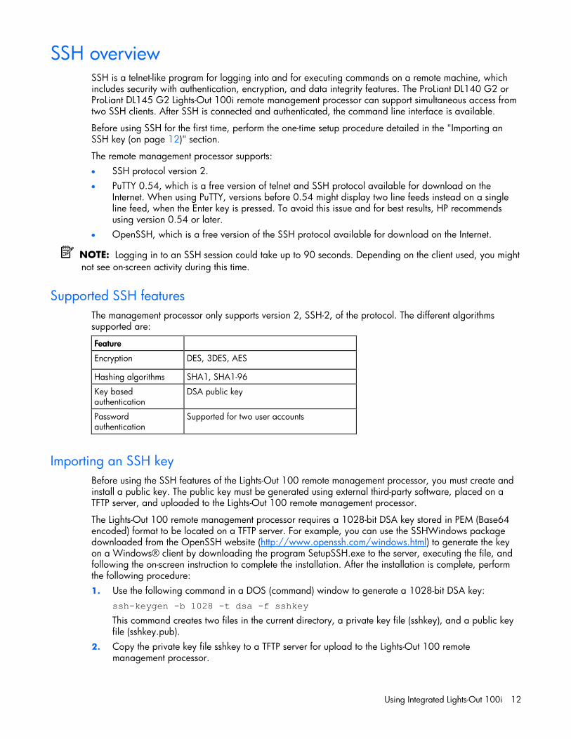
Supported SSH features The management processor only supports version 2, SSH-2, of the protocol. The different algorithms supported are:
Feature
Encryption DES, 3DES, AES
Hashing algorithms SHA1, SHA1-96
Key based authentication
DSA public key
Password authentication
Supported for two user accounts
Importing an SSH key Before using the SSH features of the Lights-Out 100 remote management processor, you must create and install a public key. The public key must be generated using external third-party software, placed on a TFTP server, and uploaded to the Lights-Out 100 remote management processor.
The Lights-Out 100 remote management processor requires a 1028-bit DSA key stored in PEM (Base64 encoded) format to be located on a TFTP server. For example, you can use the SSHWindows package downloaded from the OpenSSH website (http://www.openssh.com/windows.html) to generate the key on a Windows® client by downloading the program SetupSSH.exe to the server, executing the file, and following the on-screen instruction to complete the installation. After the installation is complete, perform the following procedure: 1. Use the following command in a DOS (command) window to generate a 1028-bit DSA key:
ssh-keygen -b 1028 -t dsa -f sshkey This command creates two files in the current directory, a private key file (sshkey), and a public key file (sshkey.pub).
2. Copy the private key file sshkey to a TFTP server for upload to the Lights-Out 100 remote management processor.
Using Integrated Lights-Out 100i 13
3. Log in to the Lights-Out 100 remote management processor, through the CLP interface with the user name "admin," change to the /./map1/firmware directory, and execute the following command from the command line: load -source <URI> -oemhpfileType key Where: • <URI> is the //tftpserver IP/path/filename to be downloaded. • tftpserver is the URL or IP address of the TFTP server containing the key file. • filename is the file name of the key file.
Using Secure Shell Using SSH
When using a Secure Shell utility to connect to a server for the first time, the utility will prompt you to accept the server's public key, sometimes referred to as a host key. Accepting this key authorizes the utility to store a copy of the public key in its own database. The utility will automatically recognize the server when future connections are attempted, by comparing the public key to the one stored in its database.
To access the remote management processor using SSH: 1. Open an SSH window. 2. When prompted, enter the IP address or DNS name, login name, and password.
Using OpenSSH
To start an OpenSSH client in Linux, use: ssh -l loginname ipaddress/dns name
Using PuTTY • To start a PuTTY session, double-click the PuTTY icon in the directory in which PuTTY is installed. • To start a PuTTY session from the command line:
• To start a connection to a server called host: putty.exe [-ssh | -telnet | -rlogin | -raw] [user@]host
• For telnet sessions, the following alternative syntax is supported: putty.exe telnet://host[:port]/
• To start an existing saved session called sessionname: putty.exe -load "session name"
CLP overview HP has worked with key industry partners within Distributed Management Task Force, Inc. to define an industry-standard set of commands. The SMASH suite will standardize manageability interfaces for servers. The ProLiant DL140 G2 or ProLiant DL145 G2 Lights-Out 100i remote management processor implements the command set defined in the Server Management Command Line Protocol Specification, 1.00 Draft. The CLP is intended to replace the simple CLI previously released with the ProLiant DL140 G2 or ProLiant DL145 G2.
The management processor functionality accessible from the SMASH CLP is a low-bandwidth interface and provides similar functionality to the Web interface. The CLP is designed for users who prefer a non-graphical interface. The CLP is accessible through the following methods: • Telnet

Using Integrated Lights-Out 100i 14
• SSH connection • Physical serial port
Using CLP The general syntax of CLP command is:
<verb> <target> <option> <property>
• Verbs—The supported verbs are: • cd
• help
• load
• reset
• set
• show
• start
• stop
• exit
• version • Target—The default target is the /. The target can be changed by the cd command or by
specifying a target on the command line. • Options—The valid options are:
• -help/-h
• -all/-a • Properties are the attributes of the target that can be modified. • Output—The output syntax is text.
The valid Boolean values for any command are yes, no, true, false, y, n, t, and f.
General notes
If the commands on the CLP command span more than one line, you will not be able to navigate between different lines.
Operating system-specific notes: • The Microsoft® Windows® 2000 telnet client does not support the Functions keys F1 through F12,
Insert, Home, and End keys. These keys will not work in a Lights-Out 100i command line session. • The Backspace key in the ProLiant DL140 G2 or ProLiant DL145 G2 Lights-Out 100i CLP
implementation is mapped to the value 0x8. Some client operating systems, Novell Linux Desktop and Red Hat Enterprise Linux 4 Desktop, map the Backspace key to the value 0x7f, which is used for the Delete key in the Windows® telnet client. The Backspace key will not work from a client from which it has value of 0x7f. For the Linux clients, using the Home or the End key lets the Lights-Out 100i CLP service remap the Backspace key to use the value 0x7f, making the key functional.
In the Windows® PuTTY client, the Backspace key can be mapped to a value of 0x8 by changing the setting for Terminal Keyboard to Control-H.
Base commands • help displays context-sensitive help.
Entering help displays all the supported commands. Entering <command help/?> displays the help message specific to that command.

Using Integrated Lights-Out 100i 15
• exit terminates the CLP session. • cd sets the current default target. The context works like a directory path. The root context for the
server is /, which is the starting point for a CLP system. By changing the context, you can shorten commands. For example, to find the current Lights-Out 100i remote management processor firmware version, you could issue the command show /map1/firmware version. However, if you issue the cd /map1/firmware command, then a simple show version command displays the information.
• show displays values of a property or contents of a collection target. For example: /./> show
/./
Targets
system1/
map1/
Properties
Verbs
cd
version
exit
show
help
The first line of information returned by the show command is the current context. In the example, / is the current context. Following the context is a list of sub targets (Targets) and properties (Properties) applicable to the current context. The verbs (Verbs) section shows what commands are applicable to this context. The show command can also be specified with an explicit or implicit context and a specific property. An explicit context is /map1/firmware and is not dependent on the current context. An implicit context assumes that the context specified is a child of the current context. If the current context is /map1, then a show firmware command displays the /map1/firmware data. If a property is not specified, then all properties are shown. In the case of the /map1/firmware context, two properties are available: version and date. If you execute show /map1/firmware date, only the date is shown.
• load moves a binary image from a URL to the map. The load command is used to take a binary image from a specific source location (specified as a URL) and place it at the specified target address. In remote management processor implementation, the firmware downloads a full image file using TFTP from the specified location and programs flash with the image. In remote management processor implementation, /map1/firmware is a valid target. The load command supports usage only with the following options. • -source <location>—This option must be specified. • (h)elp—When the option -help appears on the command line, the command ignores all
options and properties except -output (for terse or verbose output). These options are only valid for this command when the -help option is used.
• source <value>—This option tells the implementation the target from which it will transfer the binary image. The value specified must be a valid URL. The expected format is //tftpserverip/path/filename. This option is required on the command line every time the load command is executed unless -help is used. The file must be an uncompressed firmware image file, which you create using the DOS ROMPAQ utility found on the Lights-Out 100

Using Integrated Lights-Out 100i 16
Firmware Upgrade Diskette Utility available for download from the HP website (http://www.hp.com/servers/lights-out). To create the uncompressed image file, enter the following command from DOS: ROMPAQ /D <infile> <outfile> where <infile> is the ROMPAQ firmware image file and <outfile> is the filename for the uncompressed binary image file.
The load command returns any status data on the first lines. After the status data appears, one of the following lines of text displays on the next line:
<URL> transferred to <target address> (if the file is transferred) <URL> not transferred (if the file is not transferred)
Example: load -source //192.168.2.1/pub/firmwareimage.bin -oemhpfiletype csr
//192.168.2.1/pub/firmwareimage.bin transferred to /map1/firmware/fullimage
• reset causes a target to cycle from enabled to disabled and back to enabled. • set sets a property or set of properties to a specific value. • start causes a target to change state to a higher run level. • stop causes a target to change state to a lower run level. • version queries the version of the CLP implementation or other CLP elements. For example:
hpiLO-> version status=0 status_tag=COMMAND COMPLETED SM-CLP Version 1.0
Specific commands CLP syntax for specific commands is found in the sections that also describe the functionality through the Web interface.
IPMI 2.0 support The ProLiant DL140 G2 or ProLiant DL145 G2 Lights-Out 100i remote management processor supports the industry standard IPMI 2.0. The IPMI specification defines standardized, abstracted interfaces that can be used for monitoring and control functions that are built in to the platform hardware.
In addition to supporting the mandatory commands for IPMI 2.0, the following additional IPMI 2.0 features are supported by the ProLiant DL140 G2 or ProLiant DL145 G2 Lights-Out 100i remote management processor: • Additional IPMI 2.0 commands
• Get Channel Cipher Suites • Set/Get Channel Security Keys • Suspend/Resume Payload Encryption
• Payload types supported • IPMI Message • RMCP+ Open Session Request/Response • RAKP Message 1 / 2 • RAKP Message 3 / 4

Using Integrated Lights-Out 100i 17
• Authentication algorithms • RAKP-none • RAKP-HMAC-SHA1
• Integrity algorithms • None • HMAC-SHA1-96
• Confidentiality algorithms • None • AES-CBC-128
Logging in to the remote management processor You can log in to the remote management processor through a Web browser ("Logging in through a Web browser" on page 17) or through the CLP ("Logging in through the CLP" on page 18). If you are unsure of your DHCP IP address, refer to the "Configuring network access (on page 6)" section.
Logging in through a Web browser 1. Browse to the IP address of the remote management processor to access the login screen. 2. Enter your user name and password. The default user name for the Administrator account is admin,
and the default password is admin. The default user name for the Operator account is Operator, and the default password is Operator.
Accessing the system event log from the ROM-based setup 1. In the BIOS setup utility, press the right arrow (→) key to navigate to the Advanced menu. 2. Press the down arrow (↓) key to scroll to the DMI Event Logging submenu. Press the Enter key.

Using Integrated Lights-Out 100i 18
3. Press the down arrow (↓) key to scroll to the following available setup items. The available options include: • View DMI event log • Event Logging • ECC Event Logging • Mark DMI events as read • Clear all DMI event logs
4. Press the Enter key to view the options. 5. Press the Esc key to return to the previous screen, or press the F10 key to save the changes and exit
Setup.
You can also view the system event log by entering the selread command at the remote management card CLI.
Logging in through the CLP To log in to the remote management processor through the CLP and enter Terminal mode: 1. Establish a connection to the remote management processor by launching a telnet session or an SSH
session. 2. Enter the user name at the login: prompt. The default user name for the Administrator account is
admin. The default user name for the Operator account is Operator. 3. Enter the password at the password: prompt. The default password for the Administrator account is
admin. The default password for the Operator account is Operator.
To exit the CLP and enter Console mode, enter the exit command at the command prompt.
Browser main menu options From the main menu, you can access all of the basic remote management capabilities of the remote management processor.

Using Integrated Lights-Out 100i 19
Option Description
Virtual Power Accesses system power control options
Monitoring Sensors Lists all sensor information, including type, name, status, reading, and PEF settings
System Event Log Displays the system event log
Virtual Floppy Accesses the virtual floppy screen
Hardware Inventory Displays system hardware
User Administration Accesses the user configuration screen
Network Settings Accesses the network parameter settings screen
IPMI PET Configuration Accesses the PET destinations and alert policy table
Using the remote console You can access the remote console through either the BIOS console text redirection functionality or a Microsoft® Windows® Server 2003 text-based console.
BIOS console text redirection through telnet BIOS console text redirection functionality enables you to view the entire boot process remotely and make changes in the BIOS Setup Utility from a remote computer. This tool is valuable in troubleshooting and managing servers remotely.
To configure the BIOS Setup Utility on the target ProLiant DL140 G2 or ProLiant DL145 G2 system: 1. Press the F10 key during POST to enter the BIOS Setup Utility. 2. Press the right arrow (→) key to navigate to the Advanced menu. 3. Press the down arrow (↓) key to scroll down to the Console Redirection, and press the Enter key to
enter the sub-menu. 4. Select Enable. 5. Press the Esc key to return to the previous screen, or press the F10 key to save the changes and exit
Setup. 6. Follow the instructions in the "Additional network settings (on page 27)" section to set or obtain a
valid IP address. 7. Press the F10 key to save the changes and exit Setup. 8. Now that console redirection has been configured, you can view the boot process remotely by
establishing a telnet session to the IP address of the remote management processor from a client PC. Consult your operating system documentation for further details on establishing telnet sessions.
NOTE: If you encounter problems logging in to the remote console, be aware that some telnet programs might require you to enable their send line feed at end of line option. If the remote console does not respond to the Enter key, try setting this option in your telnet program.
NOTE: You must follow the instructions in the "Additional network settings (on page 27)" section to configure the network access properly.

Using Integrated Lights-Out 100i 20
Microsoft Windows EMS management Microsoft® Windows® Server 2003 provides text-based console access. You can connect a laptop to the remote management processor to perform basic management tasks on the ProLiant DL140 G2 or ProLiant DL145 G2 target system. The Windows® EMS Console, if enabled, displays the processes that are running and enables administrators to halt processes. This capability is important in cases in which video, device drivers, or other operating system features have prevented normal operation and normal corrective actions.
To enable Windows® EMS management on the target ProLiant DL140 G2 or ProLiant DL145 G2 system: 1. Press the F10 key during POST to enter BIOS Setup Utility. 2. Press the right arrow (→) key to navigate to the Advanced menu. 3. Press the down arrow (↓) key to scroll down to the EMS Console option, and press the Enter key to
enter the submenu. 4. Select Enable. 5. Press the Esc key to return to the previous screen, or press the F10 key to save the changes and exit
Setup.
You can now view the Windows® EMS management console remotely by establishing a telnet session to the IP address of the target server from a client PC. Consult your operating system documentation for further details on establishing telnet sessions.
NOTE: If you encounter problems logging in to the remote console, be aware that some telnet programs might require you to enable their send line feed at end of line option. If the remote console does not respond to the Enter key, try setting this option in your telnet program.
NOTE: You must follow the instructions in the "Additional network settings (on page 27)" section to configure the network access properly.
Controlling server power remotely Using a Web browser or the CLP, you can remotely operate the power button of a host server. Virtual power support enables you to power on, power off, and power cycle the host server. This virtual power support operates independently of the state of the operating system.
Controlling server power from a Web browser 1. Click Virtual Power on the main menu navigation bar. 2. Select the Power Control Option, and click Apply to initiate the Chassis Action.

Using Integrated Lights-Out 100i 21
3. To light the Chassis Identify LED, select the Chassis Locater LED on interval and click Identify.
Controlling server power through the CLP 1. Log into the remote management processor CLP as described in the "Logging in to the remote
management processor (on page 17)" section. 2. Change to the system1 target by entering cd system1. 3. To power on the server, enter start /system1. For example:
/./system1/> start /system1 System1 started.
4. To power off the server, enter stop /system1. For example: /./system1/> stop /system1 System1 stopped.
The -force option may also be used for the stop command. This option forces the implementation to stop the target, ignoring any policy that might cause the implementation to normally not execute the command. In remote management processor implementation, this is equivalent to a hard power down.
5. To reset the server, enter reset /system1. For example: /./system1/> reset /system1 System1 reset.
Monitoring sensors The Monitor Sensors page enables remote monitoring of the current status of major sensors of a target ProLiant DL140 G2 or ProLiant DL145 G2 server. The data for this feature can be viewed from the Monitoring Sensors Page through a web browser, or viewed through the BIOS Setup.

Using Integrated Lights-Out 100i 22
Viewing sensors data from a Web browser To access this page from a Web browser, click Monitoring Sensors on the main menu navigation bar. This page displays a snapshot of the sensor data. To update the display, click the Refresh button on the Web browser.
Viewing sensors data from the BIOS setup 1. On the target server, press the F10 key during POST to enter BIOS setup. 2. In the BIOS Setup Utility, press the right arrow (→) key to navigate to the Advanced menu. 3. Press the down arrow (↓) key to scroll to IPMI. Press the Enter key. 4. Press the down arrow (↓) key to scroll to Realtime Sensor Data. Press the Enter key. 5. The Loading data. Please wait… message appears. After this message disappears, the
Temperature and Voltage sensor data appears. This data is real-time data and is updated on a periodic basis.
Using the system event log The system event log lists a short description of each system event. Events that are recorded include abnormal temperature, fan and voltage events, system resets, and system power loss.
Accessing the system event log from a Web browser Click System Event Log on the main menu navigation bar to access the System Event Log from a web browser.
Accessing the system event log from the CLP 1. Log in to the CLP as described in the "Logging in to the remote management processor (on page
17)" section. 2. Enter cd /system1/log1. 3. Enter show to display the total number of system event records.

Using Integrated Lights-Out 100i 23
4. Enter show record<n> to display the details of a specific record. For example: /system1/log1/record1 Targets Properties
number=1
date=12/20/2004
time=15:22:05
sensordescription= Backplane +12V
eventdescription= Upper Critical-going high
eventdirection=Assertion Verbs
cd
version
exit
show
reset
oemhp
help
Accessing the system event log from the BIOS setup 1. On the target server, press the F10 key during POST to enter BIOS setup. 2. In the BIOS setup utility, press the right arrow (→) key to navigate to the Advanced menu. 3. Press the down arrow (↓) key to scroll to the IPMI submenu. Press the Enter key. 4. Press the down arrow (↓) key to scroll to the System Event Log submenu. Press the Enter key. 5. Press the down arrow (↓) key to scroll to the following available setup items. The available options
include: • Clear System Event Log • View System Event Log
6. Press the Enter key to view the options. 7. Press the Esc key to return to the previous screen, or press the F10 key to save the changes and exit
Setup.
Using the virtual floppy feature With the virtual floppy feature, you can boot the ProLiant DL140 G2 or ProLiant DL145 G2 server with a boot image residing on a remote server. To boot from a virtual floppy from a remote system: 1. Configure the TFTP server ("Configuring the TFTP server" on page 24). 2. Configuring the virtual floppy on the ProLiant DL140 G2 or ProLiant DL145 G2 server using one of
the following methods from: • BIOS Setup ("Configuring the virtual floppy from the BIOS setup" on page 24) • A Web browser • The CLP ("Configuring virtual floppy from the CLP" on page 25)
3. Reboot the ProLiant DL140 G2 or ProLiant DL145 G2 server ("Rebooting the server" on page 25).
Using Integrated Lights-Out 100i 24
Configuring the TFTP server With the virtual floppy features, you can boot the ProLiant DL140 G2 or ProLiant DL145 G2 server with a boot image residing on a remote server. To boot from a virtual floppy from a remote system: 1. Install a TFTP server on a remote system, and ensure that it is running. (TFTP servers are typically
included with Linux and are available for other operating systems as well. Consult your TFTP server documentation for further details.)
2. Create the remote boot image of the boot floppy using the HP Floppy Image Utility (flimage.exe). The Flimage.exe utility application is used to create a binary image of a 1.44-MB floppy disk. The floppy image is stored as 80 sequentially numbered binary files starting with 0. Each file represents the contents of the corresponding cylinder from the floppy disk. You can find flimage.exe on the HP website (http://www.hp.com/support).
3. Place the boot image in a subfolder (for this example, rboot is the folder containing the boot image) under the folder where the TFTP server executable program is residing. For example, if the TFTP server program TFTP.exe is in C:\tftp, then place the boot image in the folder c:\tftp\rboot.
4. Launch the executable file TFTP.exe and run TFTP.
Configuring the virtual floppy from the BIOS setup 1. On the target server, press the F10 key during POST to enter BIOS setup. 2. In the BIOS Setup Utility, press the right arrow (→) key to navigate to the Advanced menu. 3. Press the down arrow (↓) key to scroll to IPMI. Press the Enter key. 4. Press the down arrow (↓) key to scroll to VSI configuration. Press the Enter key. 5. Select Virtual Floppy, and press the Enter key. 6. Select Enabled. 7. Press the down arrow (↓) key to scroll to TFTP Server IP Address, and enter the IP address of the TFTP
server that you configured in the "Configuring the TFTP server (on page 24)" section of this guide. 8. Press the down arrow (↓) key to scroll to Floppy Timeout to change the default value. 9. Press the down arrow (↓) key to scroll to Image Directory Name. Press the Enter key. 10. In the Enter new Address Path box, enter the path to the folder containing the floppy boot image.
This path is relative to where the TFTP server program, TFTP.exe, resides. For example, if TFTP.exe is in C:\tftp and the floppy boot image in C:\tftp\rboot, then the path would be rboot.
11. Press the F10 key to save the changes and exit Setup.
Configuring virtual floppy from a Web browser 1. Log in to the remote management processor as described previously in the "Logging in to the remote
management processor (on page 17)" section. 2. Click the Virtual Floppy link from the main menu navigation bar. 3. Enter the IP address of the TFTP server that you configured in the previous section. 4. Enter the path to the folder containing the floppy boot image. This path is relative to where the TFTP
server program TFTP.exe resides. For example, if the TFTP server program TFTP.exe is in C:\tftp and the floppy boot image is in the folder c:\tftp\rboot, then the path would be rboot.

Using Integrated Lights-Out 100i 25
5. Click the Apply button.
Configuring virtual floppy from the CLP 1. Open a CLP window on the remote system, and enter cd map1/nic1 at the command prompt. 2. Configure the TFTP server path by entering the following: set oemhp_vsi_tftpserver=<path>
where <path> is the remote TFTP server IP address. For example: set oemhp_vsi_tftpserver=10.12.52.142
3. Configure the VSI path by entering the following: set oemhp_vsi_path=<path>, where <path> the path to the folder containing the floppy boot image. This path is relative to where the TFTP server program TFTP.exe resides. For example, if the TFTP server program TFTP.exe is in C:\tftp and the floppy boot image in the folder c:\tftp\rboot, then the path would be rboot. For example: set oemhp_vsi_path=rboot
4. Configure the remote file permission by entering the following: set oemhp_vsi_permission=<permission>, where <permission> is the file permission default RW (Read Write.) For example: set oemhp_vsi_permission=rw
Rebooting the server After the TFTP server and the virtual floppy are properly configured, the ProLiant DL140 G2 or ProLiant DL145 G2 server can be rebooted using the remote floppy boot image that resides on the TFTP server. The methods for rebooting the ProLiant DL140 G2 or ProLiant DL145 G2 servers are described in the "Controlling server power remotely (on page 20)" section of this guide. The server continues to reboot to the virtual floppy until the virtual floppy is disabled on the ProLiant DL140 G2 or ProLiant DL145 G2 server using the following procedure: 1. Ensure the target server is configured for network access. Follow the instructions in the "Additional
network settings (on page 27)" section of this guide. 2. On the target server, press the F10 key during POST to enter BIOS setup, and navigate to I/O
Device Configuration in the Advanced window. Press the Enter key. 3. Press the right arrow (→) key to navigate to the Advanced menu. 4. Press the down arrow (↓) key to scroll to IPMI. Press the Enter key. 5. Press the down arrow (↓) key to scroll to VSI configuration. Press the Enter key.
Using Integrated Lights-Out 100i 26
6. Select Virtual Floppy, and press the Enter key. 7. Select Disabled. 8. Press the F10 key to save the changes and exit Setup.
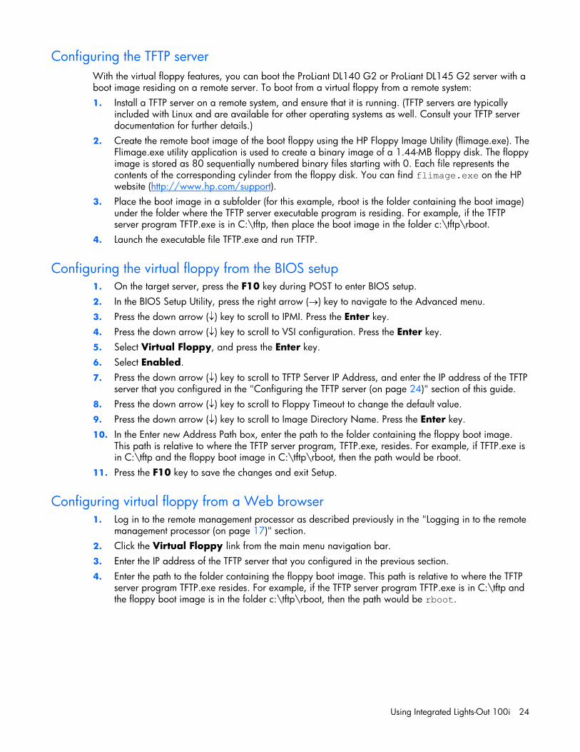
Hardware Inventory page The Hardware Inventory page enables you to remotely identify the presence of processors on a target ProLiant DL140 G2 or ProLiant DL145 G2 server.
To access this page from a web browser, click Hardware Inventory on the main menu navigation bar.
User administration The user password is stored in nonvolatile memory and can be changed through a Web browser ("Changing the password through a Web browser" on page 26) or the CLP ("Changing the password through the CLP" on page 27).
Changing the password through a Web browser 1. Click Administration on the main menu navigation bar. 2. Enter the password in the Password and Confirm Password fields. 3. Select the User Privilege level from the dropdown menu. 4. Change the user name if needed.

Using Integrated Lights-Out 100i 27
5. Click the Set button to save the changes.
Changing the password through the CLP Passwords are case-sensitive and can contain up to 16 characters. To change the user password through the CLP: 1. Log in to the CLP as described in the "Logging in to the remote management processor (on page
17)" section. 2. At the command prompt, enter cd map1/accounts. 3. Select a user by entering cd user1 or cd user2. 4. Enter a new user name by entering set username=<new username>. For example:
/./map1/accounts/user1/> set username=testuser1
5. Enter the new password by entering set password=<new password>. For example: /./map1/accounts/user1/> set password=testpswd1
6. Enter the new password when prompted. 7. Enter a new group by entering set group=<new group name>. Valid group settings are user,
operator, and oemhp. For example: /./map1/accounts/user1/> set group=user
Additional network settings You can configure additional network settings using a Web browser or the CLP.
Using Integrated Lights-Out 100i 28
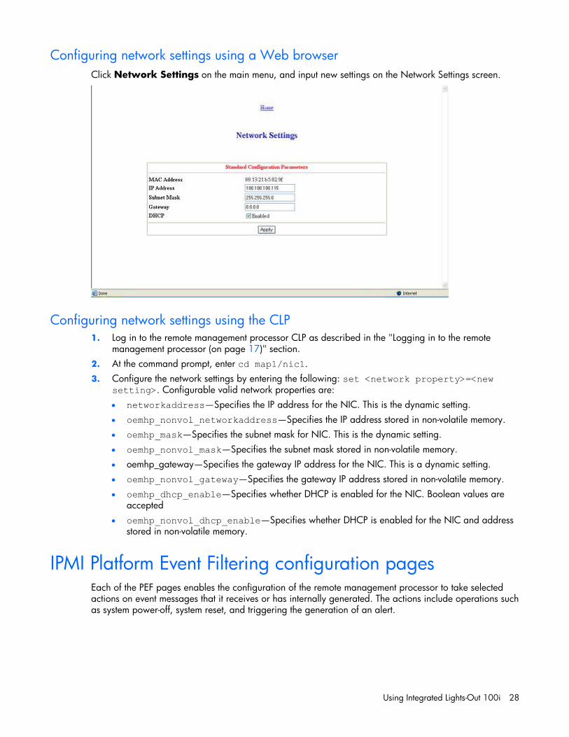
Configuring network settings using a Web browser Click Network Settings on the main menu, and input new settings on the Network Settings screen.
Configuring network settings using the CLP 1. Log in to the remote management processor CLP as described in the "Logging in to the remote
management processor (on page 17)" section. 2. At the command prompt, enter cd map1/nic1. 3. Configure the network settings by entering the following: set <network property>=<new
setting>. Configurable valid network properties are: • networkaddress—Specifies the IP address for the NIC. This is the dynamic setting. • oemhp_nonvol_networkaddress—Specifies the IP address stored in non-volatile memory. • oemhp_mask—Specifies the subnet mask for NIC. This is the dynamic setting. • oemhp_nonvol_mask—Specifies the subnet mask stored in non-volatile memory. • oemhp_gateway—Specifies the gateway IP address for the NIC. This is a dynamic setting. • oemhp_nonvol_gateway—Specifies the gateway IP address stored in non-volatile memory. • oemhp_dhcp_enable—Specifies whether DHCP is enabled for the NIC. Boolean values are
accepted • oemhp_nonvol_dhcp_enable—Specifies whether DHCP is enabled for the NIC and address
stored in non-volatile memory.
IPMI Platform Event Filtering configuration pages Each of the PEF pages enables the configuration of the remote management processor to take selected actions on event messages that it receives or has internally generated. The actions include operations such as system power-off, system reset, and triggering the generation of an alert.

Using Integrated Lights-Out 100i 29
To configure a PEF for a particular sensor, click the PEF button on the far right of that sensor on the Monitoring Sensors page, which opens the IPMI PEF Configuration page for that sensor.
The PEF Configuration page has two sections for the sensors: • Current PEF Entries • Add PEF Entry
The Current PEF Entries section includes: • Sensor Type • Sensor Name • PEF Action • PEF Control
Initially, there are no entries in the Current PEF Entries section because no PEFs have been defined. When PEF entries are defined, the PEF Control field is active and allows individual entries to be enabled, disabled, and deleted.
The Add PEF Entry section contains two main subsections: • Event Offsets are trip points (movements across thresholds) that define what type of sensor event
triggers an action. The information in this section varies from sensor to sensor. Not all checkboxes are available for all sensors. You can select any of the available checkboxes.
• PEF Action has the same information for all sensors: • Sensor Type (in this case, it is "Fan"). • Sensor Name (in this case, it is "CPU0 FAN"). • PEF Action. This dropdown menu enables you to select from Power Off (selected for this
example), Power Cycle, Hard Reset, and Send Alert (requires a systems management console supporting IPMI 1.5).
• PEF Control. This setting allows you to enable or disable each sensor. • Alert Policy. This dropdown menu, by default, shows No Alert Policy if alerts are not defined
on the PET Configuration page (as in this example). If alerts are defined in the PET Configuration page, then you can select from your defined alert policies for this particular sensor and PEF.
• Add. This button adds the new entry to the PEF Current Entry table at the top of the page.
Using Integrated Lights-Out 100i 30
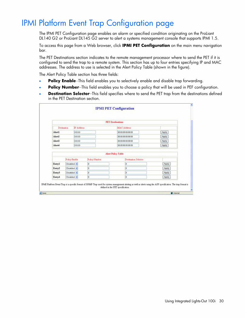
IPMI Platform Event Trap Configuration page The IPMI PET Configuration page enables an alarm or specified condition originating on the ProLiant DL140 G2 or ProLiant DL145 G2 server to alert a systems management console that supports IPMI 1.5.
To access this page from a Web browser, click IPMI PET Configuration on the main menu navigation bar.
The PET Destinations section indicates to the remote management processor where to send the PET if it is configured to send the trap to a remote system. This section has up to four entries specifying IP and MAC addresses. The address to use is selected in the Alert Policy Table (shown in the figure).
The Alert Policy Table section has three fields: • Policy Enable—This field enables you to selectively enable and disable trap forwarding. • Policy Number—This field enables you to choose a policy that will be used in PEF configuration. • Destination Selector—This field specifies where to send the PET trap from the destinations defined
in the PET Destination section.
Acronyms and abbreviations 31
Acronyms and abbreviations
BIOS
Basic Input/Output System
BMC
base management controller
CLI
Command Line Interface
CLP
command line protocol
DHCP
Dynamic Host Configuration Protocol
DSA
Digital Signature Algorithm
EMS
Emergency Management Services
HTTP
hypertext transfer protocol
IP
Internet Protocol
IPMI
Intelligent Platform Management Interface
MAC
medium access control
NIC
network interface controller

Acronyms and abbreviations 32
PEF
Platform Event Filtering
PEM
Privacy Enhanced Mail
PET
Platform Event Trap
POST
Power-On Self Test
SMASH
System Management Architecture for Server Hardware
SSH
Secure Shell
SSL
Secure Sockets Layer
TCP/IP
Transmission Control Protocol/Internet Protocol
TFTP
Trivial File Transfer Protocol
URL
uniform resource locator
VSI
virtual storage interface

Index 33
B
base management controller (BMC) 6 Basic Input/Output System (BIOS) 7 BIOS (Basic Input/Output System) 7 BMC (base management controller) 6 booting the server 23 browser, main menu 18 browsers 20
C
CLI (Command Line Interface) 17, 19 CLP (Command Line Protocol) 25 CLP (Command Line Protocol), commands 21 CLP overview 13 CLP, commands 14, 16 CLP, using 14, 21 Command Line Interface (CLI) 17, 19 command line options 14, 16 Command Line Protocol (CLP) 25 configuration procedures 6 configuration, network 6, 28 configuring the LOM processor 10
D
DHCP (Dynamic Host Configuration Protocol) 31 Digital Signature Algorithm (DSA) 11, 13 DSA (Digital Signature Algorithm) 11, 13 Dynamic Host Configuration Protocol (DHCP) 31
E
Emergency Management Services (EMS) 20 EMS (Emergency Management Services) 20 enabling TFTP 24 event log 22 event log entries 22
F
features 5, 10 features, IPMI 2.0 16 features, SSH 12
H
hardware inventory 26 HTTP (hypertext transfer protocol) 6, 10 hypertext transfer protocol (HTTP) 6, 10
I
import SSL key and certificate 10 Intelligent Platform Management Interface (IPMI) 6,
16, 28, 30 Internet Protocol (IP) 5, 6, 9 IP (Internet Protocol) 5, 6, 9 IPMI (Intelligent Platform Management Interface) 6,
16, 28, 30 IPMI support 16
L
logging in 17, 18 logging in, through a browser 17 logging in, through the CLP 18
M
MAC (medium access control) 11 Main menu functions 18 medium access control (MAC) 11 monitoring sensors 21
N
network access 6 network access, configuring 6 network interface controller (NIC) 31 network settings 6, 27, 28 network settings, additional 27 NIC (network interface controller) 31
O
operational overview 5 options, SSL 11 overview, CLP 13 overview, product 5 overview, SSH 12
Index
Index 34
overview, SSL 10
P
password, changing through a browser 26 password, changing through the CLP 27 passwords 26 PEF (Platform Event Filtering) 18, 28, 30 PEM (Privacy Enhanced Mail) 10, 12 Platform Event Filtering (PEF) 18, 28, 30 POST (Power-On Self Test) 6 power cycle server 20 powering on/off 20, 21 Power-On Self Test (POST) 6 Privacy Enhanced Mail (PEM) 10, 12 processors 26
R
reboot, server 25 remote console 5, 19 remote management processor, logging in 17 remote management processor, logging in through
CLP 17, 18 remote server power, controlling 20 remote server power, controlling using a
browser 21 remote server power, controlling using the CLP 21 requirements, SSH 13
S
Secure Shell (SSL) 12 sensor data, viewing 21, 22 serial port 7 serial port, BIOS console configuration 8 serial port, enabling 7 server management 5 SMASH (System Management Architecture for Server
Hardware) 13 SSH (Secure Shell) 12 SSH, features 12 SSL, importing key and certificate 10 SSL, overview 10 SSL, supported options 11 SSL, using 11 support, IPMI 16 system event log, access through the BIOS 23 system event log, access through the CLP 22 system event log, using 22 System Management Architecture for Server
Hardware (SMASH) 13
T
TCP/IP (Transmission Control Protocol/Internet Protocol) 8, 32
TFTP (Trivial File Transfer Protocol) 24 TFTP, configuration 24 Trivial File Transfer Protocol (TFTP) 24
U
uniform resource locator (URL) 10, 12 URL (uniform resource locator) 10, 12 user account, modifying 7, 26 user and configuration settings 7, 26
V
virtual floppy 23 virtual floppy, configuring from BIOS setup 24 virtual power 20 virtual storage interface (VSI) 24, 25 VSI (virtual storage interface) 24, 25