hp web jetadmin 10...restart the hp web jetadmin service manually 21 back up and restore hp web...
TRANSCRIPT
HP Web Jetadmin 10.3
User Guide

Copyright and License
© 2014 Copyright Hewlett-PackardDevelopment Company, L.P.
Reproduction, adaptation, or translationwithout prior written permission is prohibited,except as allowed under the copyright laws.
The information contained herein is subject tochange without notice.
The only warranties for HP products andservices are set forth in the express warrantystatements accompanying such products andservices. Nothing herein should be construedas constituting an additional warranty. HP shallnot be liable for technical or editorial errors oromissions contained herein.
Publication Date: 7/2014
Trademark Credits
Adobe®, Acrobat®, and PostScript® aretrademarks of Adobe Systems Incorporated.
Apple and the Apple logo are trademarks ofApple Computer, Inc., registered in the U.S. andother countries. iPod is a trademark of AppleComputer, Inc. iPod is for legal or rightholder-authorized copying only. Don't steal music.
Microsoft®, Windows®, Windows® XP, andWindows Vista® are U.S. registered trademarksof Microsoft Corporation.

Table of contents
1 Install and Set Up HP Web Jetadmin ................................................................................................................ 1
System Requirements ........................................................................................................................................... 1
Operating Systems .............................................................................................................................. 2
HP Web Jetadmin Server Application ............................................................................... 2
HP Web Jetadmin Client Application ................................................................................. 3
Virtual Machine (Optional Platform) ................................................................................................... 3
Server Hardware .................................................................................................................................. 4
Client Hardware ................................................................................................................................... 4
Database .............................................................................................................................................. 5
Network ............................................................................................................................................... 5
Installations and Upgrades ................................................................................................................. 5
Client Application ................................................................................................................................ 5
Shared Print Queues ............................................................................................................................ 5
Supported Devices .............................................................................................................................. 6
Host Access .......................................................................................................................................... 6
Client/Server Security ......................................................................................................................... 6
Install HP Web Jetadmin ........................................................................................................................................ 6
Install HP Web Jetadmin from the Command Line ............................................................................. 7
Install HP Web Jetadmin in Blocking Mode ......................................................................................... 9
Post-installation Tasks ....................................................................................................................................... 10
Recommended Initial Configuration Steps ....................................................................................... 10
Configure the HP Web Jetadmin Service to Restart Automatically ................................................. 11
Ports ..................................................................................................................................................................... 11
Implement SSL ..................................................................................................................................................... 13
Enable Secure Sockets Layer (SSL) ................................................................................................... 14
Important Points to Remember When Implementing SSL ............................................................... 14
Configure HTTPS (Server Certificates or SSL) ................................................................................... 15
Use a Separate Instance of Microsoft SQL Server ............................................................................................... 15
Deploy the Smart Client ....................................................................................................................................... 15
Start a Smart Client Session ............................................................................................................. 16
Configure HP Web Jetadmin to Bind to a Specific NIC ...................................................................... 17
HP Web Jetadmin Client Connection .............................................................................. 17
HP Web Jetadmin Alerts and SNMP Traps Registration ................................................. 18
HP Web Jetadmin Web Service ....................................................................................... 19
Configure the Event Notification Port .............................................................................................. 20
Configure the Firewall Software ....................................................................................................... 20
ENWW iii
Restart the HP Web Jetadmin Service Manually ................................................................................................. 21
Back Up and Restore HP Web Jetadmin .............................................................................................................. 21
Upgrade HP Web Jetadmin .................................................................................................................................. 21
Uninstall HP Web Jetadmin ................................................................................................................................. 22
Uninstall HP Web Jetadmin from the Command Line ...................................................................... 22
Manage Licenses .................................................................................................................................................. 22
2 Introduction to HP Web Jetadmin .................................................................................................................. 23
Product Support .................................................................................................................................................. 23
Print the HP Web Jetadmin Guides ................................................................................................... 23
Online Help ........................................................................................................................................ 23
Feedback about HP Web Jetadmin ................................................................................................... 24
Technical Support ............................................................................................................................. 24
Getting Around in HP Web Jetadmin ................................................................................................................... 24
Application Views in HP Web Jetadmin ............................................................................................. 24
Top Menu Bar Features ..................................................................................................................... 24
Preferences ..................................................................................................................... 26
Device Filters ................................................................................................................... 26
Device Identification ....................................................................................................... 26
Application Logging ........................................................................................................ 26
Status Bar Features ........................................................................................................................... 27
Page Layout in HP Web Jetadmin ..................................................................................................... 27
Left Navigation Pane ...................................................................................................... 28
Task Modules .................................................................................................................. 28
Docking Task Modules and Maps .................................................................................... 28
Workspace ....................................................................................................................... 29
Wizards .............................................................................................................................................. 29
Need Info Wizard ............................................................................................................. 29
Other Features .................................................................................................................................. 29
The HP Web Jetadmin Server .............................................................................................................................. 30
HP Web Jetadmin and Distributed Environments ............................................................................ 31
How the HP Web Jetadmin Service Works ...................................................................... 31
Overview of Directories and Files ..................................................................................................... 32
Microsoft SQL Database Overview .................................................................................................... 33
Low-privilege Service Account .......................................................................................................... 34
HTTP Service ...................................................................................................................................... 35
Localization ....................................................................................................................................... 36
HP Web Jetadmin Network Traffic and Behavior ............................................................................. 36
The HP Web Jetadmin Client ................................................................................................................................ 37
ClickOnce Software Installation and Launch .................................................................................... 37
Notification that Microsoft .NET Framework Is Required .............................................. 38
iv ENWW

HP Web Jetadmin Client's Sleep State .............................................................................................. 38
Shared Configuration Options for all Views ........................................................................................................ 38
General Shared Configuration Options ............................................................................................. 38
Configure the Database Settings ................................................................................... 38
Configure the Data Collection Option ............................................................................. 39
Shared Configuration Options for Network ...................................................................................... 39
Configure the SNMP Settings ......................................................................................... 39
Configure the HTTP Settings .......................................................................................... 40
Configure the HTTPS Settings ........................................................................................ 40
Configure the DNS Settings ............................................................................................ 40
Shared Configuration Options for Email ........................................................................................... 40
Configure the SMTP Settings .......................................................................................... 41
Manage the Shared Email Addresses ............................................................................. 41
Shared Configuration Options for Discovery .................................................................................... 41
Configure Large Subnets for IP Range Discoveries ........................................................ 41
Manage the IP Ranges for Discoveries ........................................................................... 42
Manage the Address Lists for Specified Address Discoveries ....................................... 42
Shared Configuration Options for Server Maintenance ................................................................... 43
Configure the Schedule for Server Maintenance ........................................................... 43
Configure the Retention Period for the Discovery History ............................................ 43
Configure the Retention Period for the Configuration History ...................................... 44
Configure the Retention Period for the Alerts History ................................................... 44
Manage the Report Data ................................................................................................. 44
Shared Configuration Options for Credentials ................................................................................. 45
All About Credentials ...................................................................................................... 45
Credentials Store .......................................................................................... 45
Credentials Delegation ................................................................................. 46
Credentials Needed ...................................................................................... 46
What happened to the HP Jetdirect Device Password? ............................... 47
Restricting Configuration by Device Group .................................................. 47
Clear the Credentials ...................................................................................................... 48
Manage the Global SNMPv1 Get Community Names ..................................................... 48
Manage the Global SNMPv1 Set Community Names ..................................................... 49
Manage the Global SNMPv3 Credentials ........................................................................ 49
Manage the Global EWS Passwords ............................................................................... 50
Manage the Global File System Passwords .................................................................... 50
Manage the Domain Credentials .................................................................................... 50
Application Management Configuration Options ............................................................................................... 50
Configure the Settings for the Application Log ................................................................................ 51
Restore the Default Roles ................................................................................................................. 51
Device Management Configuration Options ....................................................................................................... 51
ENWW v
Device Polling Configuration Options ............................................................................................... 52
Configure the Background Polling Options .................................................................... 52
Configure the Polling Options for Device Lists ............................................................... 53
Configure the Polling Options for Device Tabs .............................................................. 54
Configure the Polling Options for Device Alerts and Supplies Alerts ............................ 54
Configure the Polling Options for Supplies .................................................................... 55
Devices Configuration Options ......................................................................................................... 55
Manage Hidden Devices .................................................................................................. 55
Manage Blocked Devices ................................................................................................ 56
Device Discovery Configuration Options .......................................................................................... 56
Configure the General Settings for Device Discoveries ................................................. 56
Device Filters Configuration Options ................................................................................................ 57
Configure the Number of Days that Devices are Considered New ................................. 57
Device Tabs Configuration Options .................................................................................................. 57
Configure the General Options for Device Tabs ............................................................. 57
Configuration Options for Fleet Configurations ............................................................................... 58
Configure the Retry Settings for Device Configuration Schedules ................................ 58
Restore the Default Configuration Templates ............................................................... 58
Manage the User-defined Device Configuration Settings ............................................. 59
Manage the PJL Repository ............................................................................................ 61
Manage the Certificate Repository ................................................................................. 61
Manage the OXPd Device Function Repository .............................................................. 62
Manage the OXPd Accessory Record Repository ........................................................... 62
Manage the OXPd Authentication Agent Repository ..................................................... 62
Manage the OXPd Authorization Proxy Configuration Repository ................................ 64
Alerts Configuration Options ............................................................................................................ 65
Attach the Supplies Report to the Email Notifications for Supply Alerts ...................... 65
Manage the Custom Email Templates ............................................................................ 66
Manage the Templates for Alert Subscriptions ............................................................. 66
Configure the Settings for the Alerts Log ...................................................................... 66
Configure the Format for SNMP Traps ........................................................................... 67
Firmware Configuration Options ...................................................................................................... 67
Configure the Settings for Firmware Upgrades ............................................................. 68
Reports Configuration Options ......................................................................................................... 68
Manage the General Settings for Reports ...................................................................... 68
Configure the Data Collection Times for Reports .......................................................... 68
Supplies Configuration Options ........................................................................................................ 69
Configure the Threshold for Low Supplies ..................................................................... 69
Configure the Shop for Supplies Link in Reports ........................................................... 69
vi ENWW
3 Device Management ..................................................................................................................................... 70
All About Device Management ............................................................................................................................ 70
Device Management Task Modules .................................................................................................. 70
Device Management Options ............................................................................................................ 72
Device Tabs on Device List Pages ..................................................................................................... 72
Showing and Hiding Device Tabs .................................................................................... 72
Status Tab ....................................................................................................................... 73
Parts of the Status Tab Page ....................................................................... 73
Related Application Options for the Status Tab .......................................... 74
Config Tab ....................................................................................................................... 74
Parts of the Config Tab Page ........................................................................ 75
Configuring My Settings ............................................................................... 75
Alerts Tab ........................................................................................................................ 76
Parts of the Alerts Tab Page ........................................................................ 76
Groups Tab ...................................................................................................................... 77
Parts of the Groups Tab Page ...................................................................... 77
Reports Tab ..................................................................................................................... 77
Parts of the Reports Tab Page ..................................................................... 78
Supplies Tab .................................................................................................................... 78
Parts of the Supplies Tab Page .................................................................... 78
Shop for Supplies ......................................................................................... 79
Storage Tab ..................................................................................................................... 79
Parts of the Storage Tab Page ..................................................................... 79
Device File System Password ....................................................................... 81
Applications Tab ............................................................................................................. 81
Solutions Tab .................................................................................................................. 82
Editing Solutions .......................................................................................... 82
Install Managers ........................................................................................... 83
Capabilities Tab ............................................................................................................... 83
Troubleshoot Tab ........................................................................................................... 84
Parts of the Troubleshoot Tab Page ............................................................ 84
Firmware Tab .................................................................................................................. 84
Parts of the Firmware Tab Page .................................................................. 85
Copy Template Wizard ...................................................................................................................... 85
Export and Import Device Configuration Templates ........................................................................ 86
Reset Device Wizard .......................................................................................................................... 87
Edit Schedule Wizard ......................................................................................................................... 87
Mapping ............................................................................................................................................. 87
All About Maps ................................................................................................................ 88
Devices and Groups ...................................................................................... 88
Hidden Devices and Mapping ....................................................................... 89
ENWW vii

Activating the Maps Feature ........................................................................................... 89
Adding a Map Graphic to a Device Group ........................................................................ 89
Changing a Graphic Image for a Map .............................................................................. 89
Placing Devices and Subgroups on a Map ...................................................................... 89
Placing URLs on a Map .................................................................................................... 90
Viewing Device or Group Status ..................................................................................... 90
Sizing a Map .................................................................................................................... 91
Removing Items from a Map ........................................................................................... 91
Removing a Map from a Group ....................................................................................... 91
Device Lists .......................................................................................................................................................... 91
All About Device Lists ........................................................................................................................ 92
Pre-Defined Device Lists ................................................................................................ 92
Columns for Device Lists ................................................................................................ 93
Complex Data in Device Lists ....................................................................... 93
Columns Dependent on HP Web Jetadmin Data .......................................... 93
Columns Dependent on HP Jetdirect Data ................................................... 94
Statuses on Device Lists in HP Web Jetadmin ............................................. 95
Manipulating Columns in Device Lists .......................................................... 95
Steps for Adding or Removing Columns for Device Lists ............................ 96
Customizing Layouts for Device Lists ............................................................................ 96
Filters and Device Lists ................................................................................................... 97
Built-in Filters ............................................................................................... 97
Filter Manager and Editor ............................................................................. 98
Filtering On Special Column Types ............................................................ 100
Search Device Lists ....................................................................................................... 101
Exporting Device Data .................................................................................................. 102
Task Modules for Device Lists ........................................................................................................ 104
Device Lists - Current Tasks and Common Tasks Task Modules ................................. 104
Device Lists - Summary Task Module .......................................................................... 105
Related Application Options for Device Lists ................................................................................. 105
Printing Device Lists ........................................................................................................................ 105
Deleting Devices from Device Lists ................................................................................................ 106
Refreshing Devices .......................................................................................................................... 106
Find More Devices ........................................................................................................................... 107
Add Credentials for Devices ............................................................................................................ 107
Resolve Communication Errors for Devices That Have a New IP Address ..................................... 107
Groups ................................................................................................................................................................ 109
All About Groups ............................................................................................................................. 110
Group Representation .................................................................................................. 111
Manual versus Automatic Groups ................................................................................ 111
Group Policies ............................................................................................................... 112
viii ENWW
Example for Group Policies ........................................................................ 112
Change the Order in which HP Web Jetadmin Applies Policies ................. 112
Security Restriction Settings for Groups ...................................................................... 113
Task Modules for Groups ................................................................................................................ 113
Groups - Current Tasks and Common Tasks Task Modules ......................................... 114
Groups - Summary Task Module .................................................................................. 114
Groups - Management Task Module ............................................................................ 114
Create a New Device Group ............................................................................................................. 114
Building a Compound Filter (Groups) ........................................................................... 115
Steps for Creating a Device Group ................................................................................ 115
Moving a Device Group .................................................................................................................... 117
Add Devices to a Group ................................................................................................................... 117
Remove Devices from a Manual Group ........................................................................................... 118
Edit a Device Group ......................................................................................................................... 118
Delete a Device Group ..................................................................................................................... 120
Edit Device Group Policies ............................................................................................................... 121
Import Device Groups ..................................................................................................................... 121
Export Device Groups ...................................................................................................................... 121
Rename a Device Group .................................................................................................................. 122
View a Device Group ........................................................................................................................ 122
Search for Groups ........................................................................................................................... 122
Discovery ........................................................................................................................................................... 123
All About Device Discovery ............................................................................................................. 123
Discovering Devices with HP Web Jetadmin through Firewalls ................................... 124
Discovery Types and Methods ...................................................................................... 125
How HP Web Jetadmin Discovers Network Devices .................................. 126
How HP Web Jetadmin Discovers PC-Connected Devices ......................... 126
Quick Device Discovery .............................................................................. 128
SLP Multicast Discovery ............................................................................. 129
IP Broadcast Discovery ............................................................................... 130
IP Range Discovery ..................................................................................... 131
Specified Device Address Discovery .......................................................... 136
Active Directory Discovery ......................................................................... 138
Passive SLP Discovery ................................................................................ 140
Domain Discovery ....................................................................................... 140
WS-Discovery ............................................................................................. 141
Managing Third-Party Printers in HP Web Jetadmin ................................................... 141
Support ....................................................................................................... 142
Functionality Definitions ............................................................................ 144
Troubleshooting ......................................................................................... 145
Task Modules for Discovery ............................................................................................................ 146
ENWW ix

Discovery - Current Tasks and Common Tasks Task Modules .................................... 146
Discovery - Summary Task Module .............................................................................. 146
Discovery - Active Discoveries Task Module ................................................................ 146
Discovery - Scheduled Discoveries Task Module ......................................................... 147
Discovery - Templates Task Module ............................................................................ 147
Discovery - Quick Monitor Task Module ....................................................................... 147
Related Application Options for Discovery ..................................................................................... 148
SNMPv3 Enabled Devices ............................................................................................. 148
Network ........................................................................................................................ 148
Discover Devices (the Device Discovery Wizard) ............................................................................ 149
Discover Devices ........................................................................................................... 149
Steps to Discover Devices ............................................................................................ 150
Other Ways to Discover Devices ................................................................................... 151
Schedule a Discovery ...................................................................................................................... 151
Example for Scheduling Discoveries ............................................................................ 152
Steps to Schedule a Discovery ..................................................................................... 152
Other Ways to Schedule a Discovery ............................................................................ 153
Discovery History ............................................................................................................................ 153
Steps for Discovery History .......................................................................................... 154
Other Ways to View Discovery History ......................................................................... 154
Discovery Templates ...................................................................................................................... 154
Create a Discovery Template ....................................................................................... 154
Steps for Creating a Discovery Template .................................................. 155
Other Ways to Create a Discovery Template ............................................. 155
Apply (or Run) a Discovery Template ........................................................................... 155
Steps for Running a Discovery Template .................................................. 155
Other Ways to Run a Discovery Template ................................................. 156
Edit a Discovery Template ............................................................................................ 156
Steps for Editing a Discovery Template ..................................................... 156
Other Ways to Edit a Discovery Template ................................................. 156
Copy a Discovery Template .......................................................................................... 156
Delete a Discovery Template ....................................................................................... 157
Steps for Deleting a Discovery Template .................................................. 157
Other Ways to Delete a Discovery Template ............................................. 157
View a Discovery Template .......................................................................................... 157
Steps for Viewing a Discovery Template ................................................... 157
Other Ways to View a Discovery Template ................................................ 158
Configuration ..................................................................................................................................................... 158
All About Device Configuration ....................................................................................................... 158
Complex Data in the Confirm, Results, and Configuration History Pages ................... 159
Credentials Required for Device Configuration ............................................................ 159
x ENWW
Sensitive Device Information ....................................................................................... 159
Importing a Configuration from a File .......................................................................... 159
Task Modules for Configuration ..................................................................................................... 161
Configuration - Common Tasks Task Module .............................................................. 161
Configuration - Recent Configurations Task Module ................................................... 162
Configuration - Active Configurations Task Module .................................................... 162
Configuration - Scheduled Configurations Task Module ............................................. 162
Configuration - Templates Task Module ...................................................................... 162
Related Application Options for Configuration Management ........................................................ 163
Configure Devices ........................................................................................................................... 163
Steps to Configure Devices ........................................................................................... 163
Other Ways to Configure Devices ................................................................................. 165
View Configuration History ............................................................................................................. 165
Steps to View Configuration History ............................................................................ 165
Other Ways to View Configuration History .................................................................. 166
Schedule a Device Configuration .................................................................................................... 166
Steps for Scheduling a Device Configuration ............................................................... 167
Other Ways to Schedule a Device Configuration .......................................................... 168
Configuration Templates ................................................................................................................ 168
Volatile Configuration and HP Web Jetadmin Configuration Templates .................... 169
Adding Configuration Templates to a Group Policy ..................................................... 170
Captured Configurable Options and Configuration Templates ................................... 170
Create a Configuration Template ................................................................................................... 171
Steps to Create a Configuration Template ................................................................... 171
Other Ways to Create a Configuration Template ......................................................... 172
Edit a Configuration Template ........................................................................................................ 172
Steps to Edit a Configuration Template ....................................................................... 172
Other Ways to Edit a Configuration Template ............................................................. 172
Delete a Configuration Template ................................................................................................... 173
Steps to Delete a Configuration Template ................................................................... 173
Other Ways to Delete a Configuration Template ......................................................... 173
Copy a Configuration Template ...................................................................................................... 173
View a Configuration Template to Devices .................................................................................... 173
Steps to View a Configuration Template ..................................................................... 174
Other Ways to View a Configuration Template to Devices .......................................... 174
Apply a Configuration Template to Devices ................................................................................... 174
Steps to Apply a Configuration Template to Devices .................................................. 175
Other Ways to Apply a Configuration Template to Devices ......................................... 176
Alerts .................................................................................................................................................................. 176
All About Alerts ............................................................................................................................... 176
Alerts and HP Web Jetadmin ........................................................................................ 177
ENWW xi
What You Can Do With Alerts ........................................................................................ 177
Types of Alerts .............................................................................................................. 177
Examples of Alerts ........................................................................................................ 178
Alerts Traps Listener Port ............................................................................................................... 178
Task Modules for Alerts .................................................................................................................. 178
Alerts - Current Tasks and Alerts - Common Tasks Task Modules .............................. 178
Alerts - Active Tasks Task Module ............................................................................... 179
Alerts - Recent Alerts Task Module .............................................................................. 179
Alerts - Alert Subscriptions Task Module ..................................................................... 179
Alerts - Subscription Templates Task Module ............................................................. 179
Related Application Options for Alerts ........................................................................................... 179
Managing Device Alerts ................................................................................................................... 180
Create Alert Subscriptions .............................................................................................................. 180
Edit Alert Subscriptions .................................................................................................................. 182
Copy an Alert Subscription Template ............................................................................................. 183
Alert History .................................................................................................................................... 184
Steps for Viewing Alert History .................................................................................... 184
Other Ways to View Alert History ................................................................................. 184
Alert Subscription Templates ......................................................................................................... 184
Steps for Viewing Alert Subscription Templates ......................................................... 185
Other Ways to View an Alert Subscription Template ................................................... 185
Create Alert Subscription Templates .............................................................................................. 185
Apply an Alert Subscription Template ............................................................................................ 187
Alert Templates in Group Policies ................................................................................ 187
Steps for Applying an Alert Subscription Template ..................................................... 187
Other Ways to Apply an Alert Subscription Template ................................................. 188
Edit Alert Subscription Templates .................................................................................................. 188
Delete an Alert Subscription Template .......................................................................................... 190
Steps for Deleting an Alert Subscription Template ..................................................... 190
Other Ways to Delete an Alert Subscription Template ................................................ 191
All Subscriptions ............................................................................................................................. 191
Steps for Viewing Alert Subscriptions .......................................................................... 191
Other Ways to View Alert Subscriptions ...................................................................... 192
Firmware ............................................................................................................................................................ 192
All About Firmware ......................................................................................................................... 192
Qualifying Firmware ..................................................................................................... 192
Firmware Repository and Qualifying Firmware ......................................... 193
Qualify Feature ........................................................................................... 193
Finding Images ........................................................................................... 193
Task Modules for Firmware ............................................................................................................ 193
Firmware - Current Tasks and Common Tasks Task Modules ..................................... 193
xii ENWW
Firmware - Active Tasks Task Module .......................................................................... 194
Firmware - Scheduled Tasks Task Module ................................................................... 194
Firmware - Device Summary Task Module ................................................................... 194
Related Application Options for Firmware ..................................................................................... 194
Upgrade Firmware .......................................................................................................................... 194
Upgrading Firmware for HP Jetdirect Devices versus Printer Devices ........................ 194
Steps for Upgrading Firmware ..................................................................................... 195
Firmware Repository ....................................................................................................................... 196
View the Firmware Repository ..................................................................................... 196
Steps for Viewing the Firmware Repository .............................................. 197
Other Ways to View the Firmware Repository ........................................... 197
Get Images .................................................................................................................... 197
Steps for Getting Firmware Images ........................................................... 197
Other Ways to Get Firmware Images ......................................................... 197
Import Images ............................................................................................................... 197
Steps for Importing Firmware Images ....................................................... 197
Edit Properties for Firmware Images ........................................................................... 198
Steps for Editing a Firmware Images Properties ....................................... 198
Delete Images ............................................................................................................... 198
Steps for Deleting Firmware Images ......................................................... 198
Edit Scheduled Upgrades .............................................................................................. 198
Steps for Editing a Scheduled Firmware Upgrade Task ............................ 198
Delete Scheduled Upgrades ......................................................................................... 198
Steps for Deleting Scheduled Firmware Upgrades ................................... 198
Reports .............................................................................................................................................................. 198
All About Reports ............................................................................................................................ 199
Types of Data Collection and Available Reports .......................................................... 199
Examples of Reports .................................................................................................... 201
Task Modules for Reports ............................................................................................................... 202
Reports - Current Tasks and Report Management - Common Tasks Task Modules . . 202
Reports - Report Templates Task Module ................................................................... 203
Reports - Archived Reports Task Module ..................................................................... 203
Reports - Data Collection - Management Task Module ............................................... 203
Reports - Data Collection - Templates Task Module ................................................... 204
Reports - Scheduled Reports Task Module .................................................................. 204
Reports - Report Generation Task Module .................................................................. 204
Related Application Options for Reports ........................................................................................ 204
Available Reports ............................................................................................................................ 204
Accessory Inventory ..................................................................................................... 205
Device Inventory ........................................................................................................... 205
Device Utilization .......................................................................................................... 206
ENWW xiii

Device Utilization by User ............................................................................................. 206
Event Log History ......................................................................................................... 207
Hourly Peak Usage ........................................................................................................ 207
Supply Ordering ............................................................................................................ 207
Supply Replacement Forecast ...................................................................................... 208
Supply Usage ................................................................................................................ 208
Getting Started with Reports .......................................................................................................... 209
Data Collection ................................................................................................................................ 209
Data Collection Cycle .................................................................................................... 210
Initial Data Collection ................................................................................................... 210
Device Utilization by User and Data Collections .......................................................... 210
Reports and Alerts Traps Listener Port ..................................................... 210
Device and Printer Driver Support for Device Utilization by User ............. 210
Using Group Policies to Set Data Collection ................................................................. 211
Data Collection - Common Tasks Task Module ............................................................ 211
Add Devices to Data Collection ..................................................................................... 211
Data Collection Custom Collection Time .................................................... 211
Steps for Adding Devices to Data Collection ............................................. 212
Other Ways to Add Devices to Data Collection .......................................... 213
Remove Devices from Data Collection ......................................................................... 213
Steps for Removing Devices from Data Collection .................................... 213
Other Ways to Remove Devices from Data Collection .............................. 213
Create a Data Collection Template ............................................................................... 213
Steps for Creating a Data Collection Template ......................................... 214
Other Ways to Create a Data Collection Template .................................... 214
Apply a Data Collection Template ................................................................................ 214
Steps for Applying a Data Collection Template ......................................... 214
Other Ways to Apply a Data Collection Template ..................................... 215
Edit a Data Collection Template ................................................................................... 215
Steps for Editing a Data Collection Template ............................................ 215
Other Ways to Edit a Data Collection Template ........................................ 216
Delete a Data Collection Template ............................................................................... 216
Steps for Deleting a Data Collection Template ......................................... 216
Other Ways to Delete a Data Collection Template .................................... 216
Copy a Data Collection Template ................................................................................. 216
Data Collection Templates ........................................................................................... 216
Steps for Accessing and Working with Data Collection Templates .......... 217
Other Ways to Access a Data Collection Template .................................... 217
Data Collection Summaries .......................................................................................... 217
Steps for Data Collection Summaries ........................................................ 218
Other Ways for Data Collection Summaries .............................................. 218
xiv ENWW
Data Collection Statuses .............................................................................................. 218
Data Collection Anomalies ........................................................................................... 219
Steps for Data Collection Anomalies ......................................................... 221
Report Generation ........................................................................................................................... 221
Report Generation - Common Tasks Task Module ...................................................... 222
Generate Reports .......................................................................................................... 222
Accessory Inventory Report Settings ........................................................ 224
Device Inventory Report Settings .............................................................. 225
Device Utilization Report Settings ............................................................. 227
Device Utilization by User Report Settings ................................................ 228
Event Log History Report Settings ............................................................. 229
Hourly Peak Usage Report Settings ........................................................... 231
Supply Ordering Report Settings ............................................................... 232
Supply Replacement Forecast Report Settings ......................................... 233
Supply Usage Report Settings ................................................................... 234
Schedule a Report ......................................................................................................... 234
Steps for Scheduling a Report ................................................................... 235
Other Ways to Schedule a Report .............................................................. 236
Deleting Scheduled Reports ...................................................................... 237
Editing the Schedule for a Report .............................................................. 237
Email Reports ............................................................................................................... 237
Save Archived Reports .................................................................................................. 237
Report Templates ......................................................................................................... 238
Steps for Working with and Viewing a Report Template .......................... 238
Create a Report Template ............................................................................................ 238
Steps for Creating a Report Template ....................................................... 239
Other Ways to Create a Report Template .................................................. 240
Apply a Report Template .............................................................................................. 240
Steps for Applying a Report Template ...................................................... 240
Other Ways to Apply a Report Template ................................................... 241
Edit a Report Template ................................................................................................. 241
Steps for Editing a Report Template ......................................................... 241
Other Ways to Edit a Report Template ...................................................... 242
Delete a Report Template ............................................................................................ 242
Steps for Deleting a Report Template ....................................................... 243
Other Ways to Delete a Report Template .................................................. 243
Copy a Report Template ............................................................................................... 243
View Reports ................................................................................................................. 243
Steps for Viewing Reports .......................................................................... 243
Archived Reports ............................................................................................................................. 243
View Archived Reports .................................................................................................. 244
ENWW xv

Steps for Viewing Archived Reports .......................................................... 244
Other Ways to View Archived Reports ....................................................... 244
Delete Archived Reports ............................................................................................... 244
Steps for Deleting Archived Reports .......................................................... 244
Other Ways to Delete Archived Reports .................................................... 244
Storage .............................................................................................................................................................. 244
All About Storage ............................................................................................................................ 245
Task Modules for Storage ............................................................................................................... 245
Storage — Common Tasks Task Module ..................................................................... 245
Storage — Active Tasks Task Module .......................................................................... 246
Storage — Scheduled Tasks Task Module ................................................................... 246
Storage Repository ......................................................................................................................... 246
Import Fonts and Macros ................................................................................................................ 246
Delete Fonts and Macros ................................................................................................................ 247
Edit Properties for Storage ............................................................................................................. 247
Save to File ...................................................................................................................................... 247
Install Fonts and Macros on Devices .............................................................................................. 248
Remove Font and Macro Files from Devices .................................................................................. 248
Print Font/Macro ............................................................................................................................. 248
Storage Templates .......................................................................................................................... 249
Create a Storage Template ............................................................................................................. 249
Apply a Storage Template .............................................................................................................. 249
Edit a Storage Template ................................................................................................................. 250
Delete a Storage Template ............................................................................................................. 250
Copy a Storage Template ................................................................................................................ 250
View a Storage Template ................................................................................................................ 251
Solutions ............................................................................................................................................................ 251
All About Solutions .......................................................................................................................... 252
Task Modules for Solutions ............................................................................................................ 252
Solutions — Common Tasks Task Module ................................................................... 252
Solutions — Active Tasks Task Module ....................................................................... 253
Solutions — Scheduled Tasks Task Module ................................................................ 253
Solutions Repository ....................................................................................................................... 253
Importing Solutions ........................................................................................................................ 253
Editing Solution Settings ................................................................................................................ 254
Removing Solutions ........................................................................................................................ 254
Installing Solutions ......................................................................................................................... 255
Uninstalling Solutions ..................................................................................................................... 256
Solutions Templates ....................................................................................................................... 256
Specific Solution Templates Overviews ......................................................................................... 256
Creating a Solutions Template ....................................................................................................... 256
xvi ENWW

Deleting a Solutions Template ....................................................................................................... 257
Editing a Solutions Template .......................................................................................................... 257
Copying a Solutions Template ........................................................................................................ 257
Applying a Solutions Template ....................................................................................................... 258
4 Print Management ..................................................................................................................................... 259
All About Print Management ............................................................................................................................. 259
Print Queue Management ............................................................................................................... 259
Fleet Management of Print Queues ............................................................................. 260
Driver Management ........................................................................................................................ 260
HP’s Universal Print Driver ........................................................................................... 260
Print Management and Credentials ................................................................................................ 261
Print Management Task Modules ..................................................................................................................... 261
Print Management - Current Tasks and Print Management - Common Tasks Task Modules ....... 261
Print Management - Print Queues Task Module ............................................................................ 262
Print Management - Available Drivers Task Module ...................................................................... 262
Print Management - Active Tasks Task Module ............................................................................. 262
Print Management Options ............................................................................................................................... 262
Create Print Queue ............................................................................................................................................ 262
Steps for Creating a Print Queue .................................................................................................... 263
Other Ways to Create a Print Queue ............................................................................................... 264
Edit Print Queue ................................................................................................................................................. 264
Steps for Editing a Print Queue ....................................................................................................... 264
Other Ways to Edit a Queue ............................................................................................................ 265
Delete Print Queue ............................................................................................................................................ 265
Steps for Deleting a Print Queue .................................................................................................... 265
Other Ways to Delete a Print Queue ............................................................................................... 265
Pre-configure Driver .......................................................................................................................................... 265
Steps for Pre-configuring a Driver .................................................................................................. 266
Other Ways to Pre-Configure a Driver ............................................................................................ 266
Upload Driver to Available Drivers .................................................................................................................... 266
Steps for Uploading a Driver to Available Drivers .......................................................................... 267
Other Ways to Upload a Driver to Available Drivers ....................................................................... 267
Delete a Driver ................................................................................................................................................... 267
Steps for Deleting a Driver .............................................................................................................. 267
Other Ways to Delete a Driver ........................................................................................................ 267
Retrieve a Driver ................................................................................................................................................ 267
Steps for Retrieving a Driver ........................................................................................................... 267
Other Ways to Retrieve a Driver ..................................................................................................... 268
ENWW xvii
5 Application Management ........................................................................................................................... 269
All About Application Management .................................................................................................................. 269
Network Ports ................................................................................................................................. 269
Application Management Options ..................................................................................................................... 269
Application Management Task Modules ........................................................................................................... 269
Application Management - Current Tasks and Common Tasks Task Module ............................... 270
Application Management - Active Tasks Task Module ................................................................... 270
Application Management - Scheduled Tasks Task Module ............................................................ 270
Web Jetadmin - All Active Tasks Task Module ............................................................................... 270
Web Jetadmin - All Scheduled Tasks Task Module ........................................................................ 270
User Security ...................................................................................................................................................... 271
All About User Security ................................................................................................................... 271
Initial User Security ....................................................................................................... 271
The HP Web Jetadmin Administrator Role ................................................................... 272
Alternate Log-in Method for User Security .................................................................. 272
User Security Task Modules ............................................................................................................ 272
User Security - Current Tasks and User Security - Common Tasks Task Modules ...... 273
User Security - Roles Task Module ............................................................................... 273
User Security - Users Task Module ............................................................................... 273
User Security - Active Clients Task Module .................................................................. 273
Roles ................................................................................................................................................ 273
Restrict Roles to Device Groups ................................................................................... 274
Create a Role ................................................................................................................. 274
Edit a Role ..................................................................................................................... 275
Delete a Role ................................................................................................................. 275
Role Templates ............................................................................................................. 276
Steps for Viewing a Role ............................................................................ 276
Copy a Role Template ................................................................................ 276
Users ................................................................................................................................................ 276
Managing Users within User Groups ............................................................................ 277
Assign Roles to Users ................................................................................................... 277
Edit Users ...................................................................................................................... 279
Steps for Edit Users .................................................................................... 279
Remove Roles ............................................................................................................... 279
Steps for Removing Roles .......................................................................... 279
User Security Diagnostics ............................................................................................................... 280
Steps for Diagnostics .................................................................................................... 280
HP Web Jetadmin Management ........................................................................................................................ 280
All About HP Web Jetadmin Management ...................................................................................... 280
HP Web Jetadmin Management Task Modules .............................................................................. 280
HP Web Jetadmin - Common Tasks Task Module ........................................................ 281
xviii ENWW
HP Web Jetadmin - Management Task Module ........................................................... 281
HP Web Jetadmin - Summary Task Module ................................................................. 281
HP Web Jetadmin Installations ....................................................................................................... 281
Find HP Web Jetadmin Installations ............................................................................. 281
Web Service (WS) Discoveries .................................................................... 282
IP Broadcast Discovery ............................................................................... 282
IP Range Discovery ..................................................................................... 283
Synchronizing HP Web Jetadmin Installations ............................................................ 288
Launching HP Web Jetadmin ........................................................................................ 289
Steps for Discovering Web Jetadmin on the Same Network ....................................... 289
Steps for Removing a Web Jetadmin Instance From the List ...................................... 289
Data Synchronization ...................................................................................................................... 290
6 Device Configuration Options ..................................................................................................................... 292
Device Configuration Options for Device .......................................................................................................... 292
Alternative Letterhead Mode .......................................................................................................... 295
Asset Number .................................................................................................................................. 295
Auto Cleaning Page ......................................................................................................................... 296
Auto Continue .................................................................................................................................. 296
Auto Recovery ................................................................................................................................. 296
Auto Sense Mode ............................................................................................................................. 297
AutoSend ......................................................................................................................................... 297
AutoStore ........................................................................................................................................ 297
Browser ........................................................................................................................................... 298
Calibration Timing ........................................................................................................................... 298
Cartridge Low Action ....................................................................................................................... 298
Cartridge Out Action ........................................................................................................................ 299
Clearable Warnings ......................................................................................................................... 299
Cold Reset Media Size ..................................................................................................................... 299
Color Supply Out ............................................................................................................................. 299
Color/Black Mix ............................................................................................................................... 299
Company Name ............................................................................................................................... 300
Contact Person ................................................................................................................................ 300
Control Panel Display ...................................................................................................................... 300
Control Panel Language .................................................................................................................. 300
Courier Font Type ............................................................................................................................ 300
Date and Time ................................................................................................................................. 300
Date/Time Format ........................................................................................................................... 301
Daylight Savings Time .................................................................................................................... 301
Default Input Paper Tray ................................................................................................................ 301
Default Media Size .......................................................................................................................... 301
ENWW xix

Default Media Type ......................................................................................................................... 301
Default Print Density ....................................................................................................................... 302
Default Printer Copies ..................................................................................................................... 302
Delay Calibration at Wake/Power On ............................................................................................. 302
Device Certificates .......................................................................................................................... 302
Device Location ............................................................................................................................... 303
Device Name .................................................................................................................................... 303
Device Volumes ............................................................................................................................... 303
Duplex Binding ................................................................................................................................ 304
Duplex Blank Pages ........................................................................................................................ 304
Duplex Impressions ........................................................................................................................ 304
Economode ..................................................................................................................................... 304
Fuser Modes .................................................................................................................................... 304
FutureSmart Level .......................................................................................................................... 305
High Capacity Output Mode ............................................................................................................ 305
High Capacity Output Names .......................................................................................................... 305
Home Screen Applications .............................................................................................................. 305
Home Screen Language Selection .................................................................................................. 307
I/O Timeout to End Print Jobs ......................................................................................................... 307
Inactivity Timeout ........................................................................................................................... 307
Input Auto Continue ........................................................................................................................ 308
Input Auto Continue Timeout .......................................................................................................... 308
Instant Lamp On .............................................................................................................................. 308
Invalid Personality Reports ............................................................................................................ 308
Jam Recovery .................................................................................................................................. 308
Job Hold Timeout ............................................................................................................................ 308
Job Retention .................................................................................................................................. 309
Job Storage Limit ............................................................................................................................ 309
Key Press Sound .............................................................................................................................. 309
Keyboard Layout ............................................................................................................................. 309
Manually Feed Prompt .................................................................................................................... 309
Media Administration ...................................................................................................................... 309
Optimum Speed/Cost ...................................................................................................................... 310
Optimum Speed/Energy Usage ....................................................................................................... 310
Order Supplies % Level ................................................................................................................... 310
Original Orientation ......................................................................................................................... 310
Outgoing Servers ............................................................................................................................ 310
Output Auto Continue ..................................................................................................................... 312
Override A4/Letter .......................................................................................................................... 312
OXPd Accessory Records ................................................................................................................ 312
OXPd Authentication Agents .......................................................................................................... 313
xx ENWW
OXPd Authorization Proxy Configuration ....................................................................................... 313
OXPd Device Functions ................................................................................................................... 314
OXPd Enabled .................................................................................................................................. 314
OXPd OPS Config Settings ............................................................................................................... 314
Paper Tray Assignments ................................................................................................................. 315
PCL Form Length ............................................................................................................................. 315
PJL Configuration ............................................................................................................................ 315
Power On Calibration ...................................................................................................................... 315
Print PDF Errors ............................................................................................................................... 316
Print PS Errors ................................................................................................................................. 316
Printer Wakeup ............................................................................................................................... 316
PS Defer Media ................................................................................................................................ 316
Quick Sets ........................................................................................................................................ 316
Quiet Mode ...................................................................................................................................... 318
Replace Supplies ............................................................................................................................. 318
Resolution ....................................................................................................................................... 319
Resolution Enhancement ................................................................................................................ 319
Restore Modes ................................................................................................................................ 319
Rotate Offset ................................................................................................................................... 319
Show Date and Time ....................................................................................................................... 319
Show Network Address ................................................................................................................... 319
Size/Type Prompt ........................................................................................................................... 320
Sleep/Wake Time ............................................................................................................................ 320
Sleep Delay (Minutes) ..................................................................................................................... 320
Sleep Delay Time ............................................................................................................................. 320
Sleep Mode ...................................................................................................................................... 320
Sleep Schedule ................................................................................................................................ 321
Sleep Timer Settings ....................................................................................................................... 322
Stacker Staple Setting .................................................................................................................... 322
Stand by Fuser Mode ....................................................................................................................... 322
Stapler Offset Mode ........................................................................................................................ 322
Staples Out Override ....................................................................................................................... 322
Status Page Language .................................................................................................................... 323
Stored Job Sort Order ..................................................................................................................... 323
Supplies Status Messages on Control Panel .................................................................................. 323
Suppress Blank Pages ..................................................................................................................... 323
System Setup .................................................................................................................................. 323
System Setup Ram Disk .................................................................................................................. 324
Time Zone ........................................................................................................................................ 324
Time Zone/Daylight Saving ............................................................................................................ 324
Tray 1 Mode ..................................................................................................................................... 325
ENWW xxi

Tray Administration ........................................................................................................................ 325
Tray Setup Media Type .................................................................................................................... 325
Use Another Tray ............................................................................................................................ 325
Use Requested Tray ........................................................................................................................ 325
Device Configuration Options for Supplies ....................................................................................................... 326
Estimated Supplies Levels .............................................................................................................. 326
Supply Delay Very Low Message .................................................................................................... 327
Supply Levels Gauge ....................................................................................................................... 327
Supply Low Alerts ........................................................................................................................... 327
Supply Low Threshold ..................................................................................................................... 327
Supply Very Low Action .................................................................................................................. 328
Device Configuration Options for Copier .......................................................................................................... 328
Auto Include Margins ...................................................................................................................... 329
Color Copy Mode and Color Copy Mode With Auto ......................................................................... 329
Color Copy Option ........................................................................................................................... 329
Copier Fit To Page ........................................................................................................................... 330
Copier Reduce/Enlarge ................................................................................................................... 330
Copy - Alternative Letterhead Mode .............................................................................................. 330
Copy Background Cleanup .............................................................................................................. 330
Copy Content Orientation ............................................................................................................... 330
Copy Darkness ................................................................................................................................. 331
Copy Heavy Originals ...................................................................................................................... 331
Copy Job Auto Interrupt .................................................................................................................. 331
Copy Job Build ................................................................................................................................. 331
Copy Job Scan Ahead ...................................................................................................................... 331
Copy Optimize Text/Picture ............................................................................................................ 332
Copy Output Bin .............................................................................................................................. 332
Copy Pages Per Sheet ..................................................................................................................... 332
Copy Paper Tray Selection .............................................................................................................. 332
Copy Reduce/Enlarge ...................................................................................................................... 332
Copy Sharpness ............................................................................................................................... 332
Copy Staple ..................................................................................................................................... 333
Default Copier Copies ...................................................................................................................... 333
Default Copy Collation .................................................................................................................... 333
Default Edge-to-Edge Setting ........................................................................................................ 333
Default Image Quality ..................................................................................................................... 333
Default Number of Copies ............................................................................................................... 333
Default Number of Sides ................................................................................................................. 333
Default Original Content ................................................................................................................. 334
Default Original Density .................................................................................................................. 334
Default Original Media Size ............................................................................................................. 334
xxii ENWW
First Copy Speed .............................................................................................................................. 334
Hold Off Print Jobs During Copy ..................................................................................................... 334
Hold Off Time .................................................................................................................................. 335
Interrupt Copy Jobs ......................................................................................................................... 335
Device Configuration Options for Network ....................................................................................................... 335
Configuration Precedence .............................................................................................................. 337
Desired USB Mode ........................................................................................................................... 337
DHCP User Class Option (Tag 77) .................................................................................................... 337
DHCPv4 FQDN compliance with RFC 4702 ...................................................................................... 337
DNS Server ...................................................................................................................................... 337
ePrint Settings ................................................................................................................................ 338
Error Handling ................................................................................................................................. 338
HTTP Idle Timeout ........................................................................................................................... 339
IPP Printer Install Wizard ................................................................................................................ 339
IPv4 Information ............................................................................................................................. 339
IPv6 Information ............................................................................................................................. 339
IPX - Ethernet Frame Type .............................................................................................................. 340
IPX - Frame Type Token Ring .......................................................................................................... 340
IPX - Queue Server Job Polling Interval .......................................................................................... 341
IPX - RCFG Support Enabled ............................................................................................................ 341
IPX - SAP Broadcast Interval ........................................................................................................... 341
IPX - Source Routing ....................................................................................................................... 341
IPX Name ......................................................................................................................................... 341
Jetdirect External Print Server ........................................................................................................ 341
Job Timeout ..................................................................................................................................... 342
Locally Administered Address ........................................................................................................ 342
Link Setting ..................................................................................................................................... 342
mDNS Service Name ........................................................................................................................ 343
Mgmt Protocol ................................................................................................................................. 343
Network Enable Features ............................................................................................................... 343
Parallel Handshake ......................................................................................................................... 344
Parallel Mode .................................................................................................................................. 344
Phone Home Privacy Setting .......................................................................................................... 344
Protocol Stacks ............................................................................................................................... 345
Proxy Server .................................................................................................................................... 345
Scan Idle Timeout ............................................................................................................................ 346
SNMP Trap Destination Table ......................................................................................................... 346
Support Contact .............................................................................................................................. 347
Support Phone Number .................................................................................................................. 347
System Contact ............................................................................................................................... 347
System Location .............................................................................................................................. 347
ENWW xxiii
System Log Server .......................................................................................................................... 347
System Name .................................................................................................................................. 347
TCP Idle Timeout ............................................................................................................................. 348
TCP/IP Configuration Method ......................................................................................................... 348
TCP/IP Domain Suffix ...................................................................................................................... 348
Upload CA Certificate ...................................................................................................................... 349
Upload Jetdirect Certificate ............................................................................................................ 349
Web Services Print .......................................................................................................................... 349
WINS Server ..................................................................................................................................... 349
Device Configuration Options for Security ........................................................................................................ 350
802.1X Authentication .................................................................................................................... 351
Access Control for Device Functions ............................................................................................... 353
Access Control Level for Device Functions ..................................................................................... 355
Access Control List .......................................................................................................................... 355
Authenticate LDAP and Kerberos Without Email ........................................................................... 356
Authentication Manager ................................................................................................................. 356
Bootloader Password ...................................................................................................................... 356
Color Access Control ....................................................................................................................... 356
Color Access Control Level .............................................................................................................. 357
Control Panel Access ....................................................................................................................... 358
Default Sign In Method ................................................................................................................... 358
Device Announcement Agent .......................................................................................................... 358
Device User Accounts ...................................................................................................................... 359
Digital Sending Service ................................................................................................................... 359
Disable Direct Ports ........................................................................................................................ 359
Display Color Usage Job Log Page On Information Tab ................................................................. 359
Display Options on Information Tab ............................................................................................... 359
Embedded Web Server Password ................................................................................................... 360
Enable Host USB .............................................................................................................................. 360
Enable Secure PJL ........................................................................................................................... 360
Encrypt all web communication ..................................................................................................... 360
Encryption Strength ........................................................................................................................ 360
EWS Information Protection ........................................................................................................... 361
FIPS-140 Mode ................................................................................................................................ 361
Get Community Name ..................................................................................................................... 361
Group 1 PIN ...................................................................................................................................... 362
Group 2 PIN ...................................................................................................................................... 362
IPsec/Firewall Policy ....................................................................................................................... 362
Kerberos Authentication ................................................................................................................. 363
Accessing the Kerberos Authentication Server ............................................................ 363
Accessing the LDAP Server ........................................................................................... 364
xxiv ENWW

Searching the LDAP Database ...................................................................................... 364
Retrieve the Device User's Email Address Using Attribute Of ................... 365
Retrieve the Device User's Name Using Attribute Of ................................. 365
LDAP - Accessing the Server ........................................................................................................... 365
LDAP - Searching the Database ...................................................................................................... 365
LDAP Sign In Setup .......................................................................................................................... 365
LDAP Users and Groups ................................................................................................................... 367
Near Field Communication .............................................................................................................. 367
Novell Sign In Setup ........................................................................................................................ 367
Open/Print from USB Device ........................................................................................................... 368
PJL Password .................................................................................................................................. 368
Print Job Color Control .................................................................................................................... 368
Printer Firmware SHA1 Code Signing ............................................................................................. 368
Printer Firmware Update ................................................................................................................ 369
Restrict Color ................................................................................................................................... 369
Secure Disk Encryption Mode ......................................................................................................... 370
Secure Disk Password ..................................................................................................................... 370
Set Community Name ..................................................................................................................... 370
Smart Card Sign In Setup ................................................................................................................ 370
SNMP Version Access Control ......................................................................................................... 371
Temporary Limit Overrides ............................................................................................................. 371
Usage Limit and Reset Period ......................................................................................................... 372
Usage Limits for Permission Sets ................................................................................................... 372
User PIN Authentication .................................................................................................................. 373
Windows Sign In Setup .................................................................................................................... 373
Windows Users and Groups ............................................................................................................ 374
Device Configuration Options for Projector ...................................................................................................... 374
Auto-search ..................................................................................................................................... 375
Auto-sync VGA ................................................................................................................................. 375
Power .............................................................................................................................................. 375
Requested Source ........................................................................................................................... 375
Device Configuration Options for Wireless ....................................................................................................... 375
802.11 b/g/n ................................................................................................................................... 375
Enable Wireless Direct .................................................................................................................... 378
Enable Wireless Station .................................................................................................................. 378
Radio State ...................................................................................................................................... 378
Wireless Direct ................................................................................................................................ 378
Device Configuration Options for Fax ............................................................................................................... 379
Blocked Fax List .............................................................................................................................. 380
Fax Activity Log ............................................................................................................................... 380
Fax Answer Mode ............................................................................................................................ 380
ENWW xxv

Fax Answer Mode Settings .............................................................................................................. 381
Fax Archive ...................................................................................................................................... 381
Fax Archive Setting ......................................................................................................................... 381
Fax Archiving ................................................................................................................................... 381
Fax Billing Code ............................................................................................................................... 383
Fax Forwarding ............................................................................................................................... 383
Fax General ..................................................................................................................................... 383
Fax Header ...................................................................................................................................... 383
Fax Header Settings ........................................................................................................................ 384
Fax Maximum Baud Rate ................................................................................................................ 384
Fax Maximum Baud Rate - Receive ................................................................................................. 384
Fax Maximum Baud Rate - Send ..................................................................................................... 384
Fax Modem Settings ........................................................................................................................ 384
Fax Notification ............................................................................................................................... 385
Fax Number Confirmation ............................................................................................................... 385
Fax Printing ..................................................................................................................................... 385
Fax Printing Schedule ..................................................................................................................... 386
Fax Receive ...................................................................................................................................... 386
Fax Receive - Disposition ................................................................................................................ 387
Fax Receive - Other Options ........................................................................................................... 387
Fax Receive - Setup ......................................................................................................................... 387
Fax Receive Settings ....................................................................................................................... 387
Fax Reporting and Error Corrections .............................................................................................. 388
Fax Reports and Logs ...................................................................................................................... 388
Fax Resolution Quality .................................................................................................................... 388
Fax Ring Burst Off Time .................................................................................................................. 389
Fax Ring Frequency ......................................................................................................................... 389
Fax Send .......................................................................................................................................... 389
Fax Send - Dialing Mode .................................................................................................................. 389
Fax Send - Other Options or Other Settings ................................................................................... 389
Fax Send - Resolution ..................................................................................................................... 390
Fax Send - Setup ............................................................................................................................. 390
Fax Send Settings ............................................................................................................................ 390
Fax Send Setup ................................................................................................................................ 394
Fax Service ...................................................................................................................................... 396
Fax Time Format ............................................................................................................................. 396
Fax Transmit Signal Loss ................................................................................................................ 397
Import Speed Dials .......................................................................................................................... 397
LAN Fax Service Settings ................................................................................................................ 397
PC Fax Send ..................................................................................................................................... 398
TCF Settings .................................................................................................................................... 399
xxvi ENWW
Device Configuration Options for Embedded Web Server ................................................................................ 399
Embedded Web Server Configuration Options ............................................................................... 399
Embedded Web Server Language Settings .................................................................................... 399
Embedded Web Server Mail Settings .............................................................................................. 400
Embedded Web Server Other Links ................................................................................................ 400
Embedded Web Server URL ............................................................................................................ 400
Time Services .................................................................................................................................. 401
Device Configuration Options for File System .................................................................................................. 401
File System External Access ........................................................................................................... 401
File System Password ..................................................................................................................... 401
Secure File Erase Mode ................................................................................................................... 402
Device Configuration Options for Digital Sending ............................................................................................ 402
Activity Log ...................................................................................................................................... 404
Address Book Management ............................................................................................................ 404
Administrator Information .............................................................................................................. 404
Advanced Search Options ............................................................................................................... 405
Clear All Network Folders ............................................................................................................... 405
Default Messages Settings ............................................................................................................. 406
Default Notification Settings for Email .......................................................................................... 407
Default Scan Settings for Email ...................................................................................................... 407
Device Contacts Import ................................................................................................................... 408
Digital Sending - Accessing the LDAP Server ................................................................................. 408
Digital Sending - Auto Reset Settings ............................................................................................ 410
Digital Sending - Default ‘From:’ Address ...................................................................................... 410
Digital Sending - Default Scanner Settings .................................................................................... 411
Digital Sending - Email Attachment Settings ................................................................................. 411
Email Address Validation ................................................................................................................ 412
Email Address/Message Settings ................................................................................................... 412
Email File Settings ........................................................................................................................... 414
Email Message Text ........................................................................................................................ 415
Email Notification Settings ............................................................................................................. 415
Email Scan Settings ......................................................................................................................... 415
Enable Device Fax Archive Settings ................................................................................................ 416
Enable Save to Network Folder ...................................................................................................... 416
Enable Save to SharePoint .............................................................................................................. 417
Enable Save to USB ......................................................................................................................... 417
Enable Send to Email ...................................................................................................................... 417
Folder Access Settings .................................................................................................................... 417
Import/Export Address Book .......................................................................................................... 417
LDAP Search Method ....................................................................................................................... 418
LDAP Settings .................................................................................................................................. 418
ENWW xxvii
Network Folder File Settings .......................................................................................................... 420
Network Folder Notification Settings ............................................................................................. 421
Network Folder Scan Settings ........................................................................................................ 421
Network Folder Setup ..................................................................................................................... 422
OXPd 1.4 Configuration ................................................................................................................... 423
Personal Contacts Setup ................................................................................................................. 424
Replicate MFP .................................................................................................................................. 424
Reset Copy Send Timeout ............................................................................................................... 424
Scan To Folder Predefined Jobs ...................................................................................................... 424
Send to Network Folder .................................................................................................................. 426
Send to Network Folder - MSeries or later ..................................................................................... 426
SMTP Gateway Settings .................................................................................................................. 426
SMTP Multiple Gateway Settings .................................................................................................... 427
USB File Settings ............................................................................................................................. 427
USB Notification Settings ................................................................................................................ 428
USB Scan Settings ........................................................................................................................... 429
7 End User License Agreement ....................................................................................................................... 430
Index ........................................................................................................................................................... 431
xxviii ENWW
1 Install and Set Up HP Web Jetadmin
● System Requirements
● Install HP Web Jetadmin
● Post-installation Tasks
● Ports
● Implement SSL
● Use a Separate Instance of Microsoft SQL Server
● Deploy the Smart Client
● Restart the HP Web Jetadmin Service Manually
● Back Up and Restore HP Web Jetadmin
● Upgrade HP Web Jetadmin
● Uninstall HP Web Jetadmin
● Manage Licenses
When you install HP Web Jetadmin, you only need to install it on one hardware platform that meets therecommended minimum requirements (System Requirements on page 1) and is centrally accessible onthe network. You may then access the software from any supported Windows desktop on the network andmanage all supported network-connected peripherals.
HP Web Jetadmin offers several installation options. If you have installed a previous version ofHP Web Jetadmin, you can choose to upgrade the previous version or install a new copy. Upgrading an olderversion preserves your settings for discovery options and groups and is most likely the best choice if youhave already been using HP Web Jetadmin.
NOTE: Every release of HP Web Jetadmin contains new features and improvements to existing features. Inan environment where a previous release of HP Web Jetadmin is integrated into critical business operations,HP recommends that you fully test and qualify a new release before implementing that release into fullproduction.
Read all of the support materials before you implement HP Web Jetadmin. For current information aboutHP Web Jetadmin, see the Late Breaking News for HP Web Jetadmin 10.3 and the HP Web Jetadmin 10.3Supported Devices Readme. These documents are available from the HP Support Center.
NOTE: If the installation stops with a warning that a reboot is required, reboot the host on which theHP Web Jetadmin installer is running. Then relaunch the installer to continue the installation.
System Requirements● Operating Systems
● Virtual Machine (Optional Platform)
● Server Hardware
● Client Hardware
ENWW System Requirements 1
● Database
● Network
● Installations and Upgrades
● Client Application
● Shared Print Queues
● Supported Devices
● Host Access
● Client/Server Security
HP Web Jetadmin includes network device communication protocols and internal components that manageapplication and device data. These components extend the capabilities of HP Web Jetadmin and improveusage and performance in device lists, columns, and filtering functions.
HP Web Jetadmin is supported on platforms that have Microsoft Windows and .NET Framework high-priorityupdates. During each development cycle, HP regularly tests HP Web Jetadmin on platforms that have thecurrent Microsoft updates. HP investigates all post-release software issues that customers report. For moreinformation about the current software issues, see the Late Breaking News for HP Web Jetadmin 10.3. Thisdocument is available from the HP Support Center.
HP Web Jetadmin requires the Windows HTTP SSL service. HP Web Jetadmin uses SSL to communicate withnewer HP devices through port 8050.
Operating Systems
● HP Web Jetadmin Server Application
● HP Web Jetadmin Client Application
NOTE: For more information about a specific Microsoft operating system, go to www.microsoft.com.
HP Web Jetadmin Server Application
Supported operating systems
● Microsoft Windows Server 2012 R2
● Microsoft Windows Server 2012
● Microsoft Windows Server 2008 R2 SP1
● Microsoft Windows Server 2008 R2
● Microsoft Windows 7 SP1 (64-bit edition only)
2 Chapter 1 Install and Set Up HP Web Jetadmin ENWW

Notes
● HP no longer supports or tests HP Web Jetadmin installations on Microsoft operating systems that werereleased prior to the supported operating systems listed above.
● Beginning with HP Web Jetadmin 10.3 SR6, Microsoft .NET Framework 4.5 or later is required in additionto .NET Framework 3.5 SP1 because HP Web Jetadmin supports Transport Layer Security (TLS) 1.1 and1.2. Some of the supported operating systems listed above already ship with .NET Framework 4.5 orlater.
If the HP Web Jetadmin installer does not detect .NET Framework 3.5 SP1 and .NET Framework 4.5 orlater, the installer provides the appropriate installation instructions and Microsoft URL todownload .NET Framework.
● The supported operating systems listed above include Windows Installer 4.5. If Windows Installer 4.5 isnot already installed, the HP Web Jetadmin installer provides the appropriate Microsoft URL todownload Windows Installer 4.5.
● Local administrator access is required to install or upgrade HP Web Jetadmin.
● Production HP Web Jetadmin installations are restricted to dedicated hosts. Running HP Web Jetadminon systems that are also mail servers, DNS servers, domain controllers, and so on is not supported.
HP Web Jetadmin Client Application
Supported operating systems
● Microsoft Windows Server 2012 R2
● Microsoft Windows Server 2012
● Microsoft Windows Server 2008 R2 SP1
● Microsoft Windows Server 2008 R2
● Microsoft Windows 8.1
● Microsoft Windows 8
● Microsoft Windows 7 SP1
Notes
● Beginning with HP Web Jetadmin 10.3 SR6, Microsoft .NET Framework 4.5 or later is required in additionto .NET Framework 3.5 SP1 because HP Web Jetadmin supports Transport Layer Security (TLS) 1.1 and1.2. Some of the supported operating systems listed above already ship with .NET Framework 4.5 orlater.
If the HP Web Jetadmin installer does not detect .NET Framework 3.5 SP1 and .NET Framework 4.5 orlater, the installer provides the appropriate installation instructions and Microsoft URL todownload .NET Framework.
Virtual Machine (Optional Platform)
Recommended requirements
HP recommends the following virtualization solutions:
● VMware ESX
● Microsoft Hyper-V
ENWW System Requirements 3

Notes
● For a VMware server, the virtual machine network must be set to bridged to facilitateHP Web Jetadmin communications.
● It is very important to configure VMware so that its guest or virtual systems have enough resources tosupport HP Web Jetadmin and Microsoft SQL Server. To ensure that the appropriate resources areprovisioned, see the support documentation for the version of VMware you are using.
Server Hardware
Recommended requirements
HP recommends the following hardware configuration for the server:
● 4 or more processor cores
● 2.8 GHz or higher processor speed
● 4 GB or more of RAM
● 4 GB of available storage
Minimum requirements
Although you can use the following hardware configuration for the server, HP does not recommend that youuse it for production installations. HP does not test HP Web Jetadmin on this hardware configuration and,therefore, cannot guarantee the results.
● 2 processor cores
● 2.33 GHz processor speed
● 3 GB of RAM (2 GB is required for the HP Web Jetadmin Service)
NOTE: HP Web Jetadmin uses a value of 3,072 MB to qualify a system as having 3 GB of RAM.
● 4 GB of available storage
Notes
● Recent software improvements have increased resource capacity requirements. HP stronglyrecommends the 64-bit editions of Windows and 4 GB or more of RAM for production HP Web Jetadmininstallations.
● Storage requirements vary depending on the implementation, database, and migration from previousversions.
● NTFS is the only supported file system.
● If the HP Web Jetadmin installer determines that less than 1 GB of RAM is installed, the installer displaysa message stating that 3 GB of RAM is required.
Client Hardware
Recommended requirements
HP recommends the following hardware configuration for the client:
● PC with 2.4 GHz processor
● 64-bit system with 4 GB of RAM
4 Chapter 1 Install and Set Up HP Web Jetadmin ENWW
● Client display with a minimum resolution of 1024 x 768
● Optimized for Normal font size
● Default DPI only
Minimum requirements
Although you can use the following hardware configuration for the client, HP does not recommend that youuse it for production installations. HP does not test HP Web Jetadmin on this hardware configuration and,therefore, cannot guarantee the results.
● PC with 1.8 GHz processor
● 32-bit or 64-bit system with 2 GB of RAM
● Client display with a minimum resolution of 1024 x 768
● Optimized for Normal font size
● Default DPI only
Database
The 64-bit HP Web Jetadmin installation package contains and automatically installs the Microsoft SQLServer 2008 Express Edition (64-bit) database.
NOTE: For more information about configuring HP Web Jetadmin to use Microsoft SQL Server instead ofSQL Server Express, see Use a Separate Instance of Microsoft SQL Server on page 15.
Network
The HP Web Jetadmin installer requires one active IPv4 connection. If an active IPv4 connection is notavailable, the installer fails.
Installations and Upgrades
Local administrator access is required to install or upgrade HP Web Jetadmin.
Client Application
The HP Web Jetadmin client application requires the following:
● Internet Explorer 8, 9, 10, or 11
● Display with a minimum resolution of 1024 x 768
Notes
● Internet Explorer is required to start the HP Web Jetadmin client application. For browser requirementsand limitations, see the support documentation for the Windows operating system you are using.
● Administrator access is not required to run the HP Web Jetadmin client application.
● A maximum of 15 concurrent client sessions are allowed.
Shared Print Queues
To create shared print queues, HP Web Jetadmin requires one of the following operating systems:
ENWW System Requirements 5
● Windows XP Professional (32-bit)
● Windows Server 2003 (32-bit)
NOTE: HP does not support or test print queue creation and print path management via HP Web Jetadminon any operating systems other than those listed above.
Supported Devices
HP Web Jetadmin supports HP devices and third-party devices that are connected through HP Jetdirect printservers. HP Web Jetadmin also supports third-party devices that are standard printer MIB compliant and areconnected to the network. For third-party devices, HP Web Jetadmin provides basic capabilities as well asmore robust capabilities if the devices are used with HP-certified plug-ins for HP Web Jetadmin.
NOTE: If the following devices use a Universal Plug-in (UPI), WS Discovery must be enabled on the devices:
● HP LaserJet Pro
● HP Officejet Pro
● HP FutureSmart with firmware versions earlier than 3.2.3
If WS Discovery is disabled on HP LaserJet Pro and HP Officejet Pro devices, HP Web Jetadmin uses the correctUPI and displays a Device Communication Error status for the devices after a device discovery or full refreshis performed.
If WS Discovery is disabled on HP FutureSmart devices with firmware versions earlier than 3.2.3,HP Web Jetadmin uses a generic device model instead of the correct UPI after a device discovery or fullrefresh is performed.
Host Access
For the application host, local administrator access is required to install or upgrade HP Web Jetadmin.
For the client host, local user access is required to access the HP Web Jetadmin client application andadministrator access is required to install .NET Framework.
Client/Server Security
Microsoft domain or locally managed Windows users and passwords are required.
Notes
● HP tests HP Web Jetadmin in Microsoft Active Directory domains.
● Users must be a member of an HP Web Jetadmin server administrator group or designated as one of thefollowing in the HP Web Jetadmin User settings:
◦ Windows local security group
◦ Active Directory security group
◦ Local individual user account
◦ Active Directory domain user account
Install HP Web Jetadmin● Install HP Web Jetadmin from the Command Line
● Install HP Web Jetadmin in Blocking Mode
6 Chapter 1 Install and Set Up HP Web Jetadmin ENWW
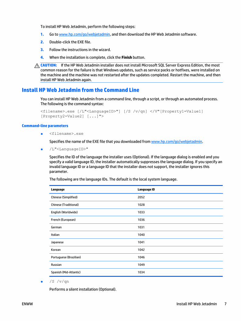
To install HP Web Jetadmin, perform the following steps:
1. Go to www.hp.com/go/webjetadmin, and then download the HP Web Jetadmin software.
2. Double-click the EXE file.
3. Follow the instructions in the wizard.
4. When the installation is complete, click the Finish button.
CAUTION: If the HP Web Jetadmin installer does not install Microsoft SQL Server Express Edition, the mostcommon reason for the failure is that Windows updates, such as service packs or hotfixes, were installed onthe machine and the machine was not restarted after the updates completed. Restart the machine, and theninstall HP Web Jetadmin again.
Install HP Web Jetadmin from the Command Line
You can install HP Web Jetadmin from a command line, through a script, or through an automated process.The following is the command syntax:
<filename>.exe [/L"<LanguageID>"] [/S /v/qn] </V"[Property1=Value1] [Property2=Value2] [...]">
Command-line parameters
● <filename>.exe
Specifies the name of the EXE file that you downloaded from www.hp.com/go/webjetadmin.
● /L"<LanguageID>"
Specifies the ID of the language the installer uses (Optional). If the language dialog is enabled and youspecify a valid language ID, the installer automatically suppresses the language dialog. If you specify aninvalid language ID or a language ID that the installer does not support, the installer ignores thisparameter.
The following are the language IDs. The default is the local system language.
Language Language ID
Chinese (Simplified) 2052
Chinese (Traditional) 1028
English (Worldwide) 1033
French (European) 1036
German 1031
Italian 1040
Japanese 1041
Korean 1042
Portuguese (Brazilian) 1046
Russian 1049
Spanish (Mid-Atlantic) 1034
● /S /v/qn
Performs a silent installation (Optional).
ENWW Install HP Web Jetadmin 7
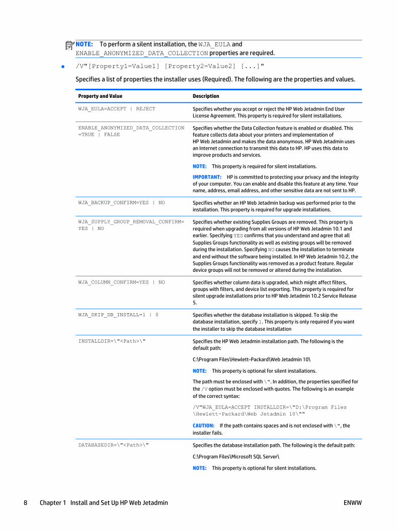
NOTE: To perform a silent installation, the WJA_EULA andENABLE_ANONYMIZED_DATA_COLLECTION properties are required.
● /V"[Property1=Value1] [Property2=Value2] [...]"
Specifies a list of properties the installer uses (Required). The following are the properties and values.
Property and Value Description
WJA_EULA=ACCEPT | REJECT Specifies whether you accept or reject the HP Web Jetadmin End UserLicense Agreement. This property is required for silent installations.
ENABLE_ANONYMIZED_DATA_COLLECTION=TRUE | FALSE
Specifies whether the Data Collection feature is enabled or disabled. Thisfeature collects data about your printers and implementation ofHP Web Jetadmin and makes the data anonymous. HP Web Jetadmin usesan Internet connection to transmit this data to HP. HP uses this data toimprove products and services.
NOTE: This property is required for silent installations.
IMPORTANT: HP is committed to protecting your privacy and the integrityof your computer. You can enable and disable this feature at any time. Yourname, address, email address, and other sensitive data are not sent to HP.
WJA_BACKUP_CONFIRM=YES | NO Specifies whether an HP Web Jetadmin backup was performed prior to theinstallation. This property is required for upgrade installations.
WJA_SUPPLY_GROUP_REMOVAL_CONFIRM=YES | NO
Specifies whether existing Supplies Groups are removed. This property isrequired when upgrading from all versions of HP Web Jetadmin 10.1 andearlier. Specifying YES confirms that you understand and agree that allSupplies Groups functionality as well as existing groups will be removedduring the installation. Specifying NO causes the installation to terminateand end without the software being installed. In HP Web Jetadmin 10.2, theSupplies Groups functionality was removed as a product feature. Regulardevice groups will not be removed or altered during the installation.
WJA_COLUMN_CONFIRM=YES | NO Specifies whether column data is upgraded, which might affect filters,groups with filters, and device list exporting. This property is required forsilent upgrade installations prior to HP Web Jetadmin 10.2 Service Release5.
WJA_SKIP_DB_INSTALL=1 | 0 Specifies whether the database installation is skipped. To skip thedatabase installation, specify 1. This property is only required if you wantthe installer to skip the database installation
INSTALLDIR=\"<Path>\" Specifies the HP Web Jetadmin installation path. The following is thedefault path:
C:\Program Files\Hewlett-Packard\Web Jetadmin 10\
NOTE: This property is optional for silent installations.
The path must be enclosed with \". In addition, the properties specified forthe /V option must be enclosed with quotes. The following is an exampleof the correct syntax:
/V"WJA_EULA=ACCEPT INSTALLDIR=\"D:\Program Files\Hewlett-Packard\Web Jetadmin 10\""
CAUTION: If the path contains spaces and is not enclosed with \", theinstaller fails.
DATABASEDIR=\"<Path>\" Specifies the database installation path. The following is the default path:
C:\Program Files\Microsoft SQL Server\
NOTE: This property is optional for silent installations.
8 Chapter 1 Install and Set Up HP Web Jetadmin ENWW

Property and Value Description
If the directory name contains spaces, you must use the Windows short-path notation. To find the short-path notation, issue the followingcommand: Dir *. /x
The path must be enclosed with \". In addition, the properties specified forthe /V option must be enclosed with quotes.
The following are examples of the correct syntax:
● /V"WJA_EULA=ACCEPT DATABASEDIR=\"D:\SQLServer \""
● /V"WJA_EULA=ACCEPT DATABASEDIR=\"C:\Program~1\SQLServer\""
CAUTION: If the path contains spaces and is not enclosed with \", theinstaller fails.
Examples of the command-line syntax
NOTE: The following examples assume that the name of the installation file is WjaSetup-x64.exe.
● To perform a basic silent installation, enter the following command:
WjaSetup-x64.exe /S /v/qn /V"WJA_EULA=ACCEPT ENABLE_ANONYMIZED_DATA_COLLECTION=TRUE"
● To start the installer in Spanish, enter the following command:
WjaSetup-x64.exe /L"1034"
● To perform a silent installation with HP Web Jetadmin installed on C:\WJA, enter the followingcommand:
WjaSetup-x64.exe /S /v/qn /V"WJA_EULA=ACCEPT ENABLE_ANONYMIZED_DATA_COLLECTION=TRUE INSTALLDIR=\"C:\WJA\""
● To perform a silent installation with HP Web Jetadmin installed on C:\WJA and the database installed onC:\WJADB, enter the following command:
WjaSetup-x64.exe /S /v/qn /V"WJA_EULA=ACCEPT ENABLE_ANONYMIZED_DATA_COLLECTION=TRUE INSTALLDIR=\"C:\WJA\" DATABASEDIR=\"C:\WJADB\""
● To perform a silent upgrade, enter the following command:
WjaSetup-x64.exe /S /v/qn /V"WJA_EULA=ACCEPT ENABLE_ANONYMIZED_DATA_COLLECTION=TRUE INSTALLDIR=\"C:\WJA\" DATABASEDIR=\"C:\WJADB\" WJA_BACKUP_CONFIRM=YES WJA_SUPPLY_GROUP_REMOVAL_CONFIRM=YES WJA_COLUMN_CONFIRM=YES"
Install HP Web Jetadmin in Blocking Mode
You can run a silent installation in blocking mode from the command line. The following is the commandsyntax:
start /wait <ProgramAndArguments>
The following is an example of the command:
NOTE: This example assumes that the name of the installation file is WjaSetup-x64.exe.
ENWW Install HP Web Jetadmin 9
start /wait WjaSetup-x64.exe /S /v/qn /V"WJA_EULA=ACCEPT INSTALLDIR=\"C:\wja\" DATABASEDIR=\"C:\wjadb\""
start /wait "C:\temp\WjaSetup-x64.exe /S /v/qn /V"WJA_EULA=ACCEPT ENABLE_ANONYMIZED_DATA_COLLECTION=TRUE INSTALLDIR=\"C:\wja\" DATABASEDIR=\"C:\wjadb\"""
Post-installation Tasks● Recommended Initial Configuration Steps
● Configure the HP Web Jetadmin Service to Restart Automatically
NOTE: The HP Web Jetadmin server will start automatically as a Microsoft Service. The HP Web Jetadminserver cannot accept HP Web Jetadmin client connections until the HP Web Jetadmin server has fully loadedall services into memory. Dependent upon your HP Web Jetadmin server available system resources, it maytake 1-2 minutes for all services to completely load after initial server installation or server reboot.
The first time you launch HP Web Jetadmin after installation, a pop-up dialog is displayed stating that nodevices have been discovered. You can opt to launch discovery settings at this point.
Once the installation is complete, HP Web Jetadmin can be launched from a supported browser by enteringthe hostname or IP address of the computer on which it is installed, followed by the port number and path.Typical default port numbers for Web services have a value of 80. Since HP Web Jetadmin may be runningsimultaneously with another Web service on the same computer, HP Web Jetadmin uses a port number of8000. If desired, the port value may be altered.
Here is an example of the URL used to activate HP Web Jetadmin on a supported Windows desktop:
http://myhost:8000
Recommended Initial Configuration Steps
After HP Web Jetadmin is installed, some of the initial steps that you should take to begin managing devicesand the print environment include configuring the options that are shared throughout HP Web Jetadmin,running a discovery, and configuring various other features.
Shared configuration options include the database, network (for example, SNMP and HTTPS), discovery,server maintenance, and credentials. To configure these options, go to Tools > Options > Shared, and thennavigate to the appropriate category. For more information about a specific option, see the online Help forthat option.
Finding devices on the network might be as simple as enabling HP Web Jetadmin to passively listen fordevices on the network. Finding devices might be as complex as working with the IT team to map the entire IPnetwork, and then running an IP Range discovery to compile a complete inventory of network-connecteddevices. You can also use many of the same settings and techniques to discover PC-connected devices.Before you plan and implement a device discovery strategy, carefully review the information aboutdiscoveries in the HP Web Jetadmin documentation and white papers.
You should configure features such as Roles, Users, Alerts, and Device Groups before you begin usingHP Web Jetadmin. For more information about a specific feature, see the appropriate section in theHP Web Jetadmin documentation and the HP Web Jetadmin white papers.
NOTE: The HP Web Jetadmin documentation and white papers are available from the HP Support Center.
10 Chapter 1 Install and Set Up HP Web Jetadmin ENWW
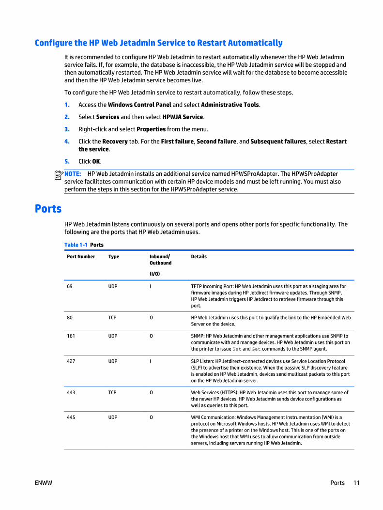
Configure the HP Web Jetadmin Service to Restart Automatically
It is recommended to configure HP Web Jetadmin to restart automatically whenever the HP Web Jetadminservice fails. If, for example, the database is inaccessible, the HP Web Jetadmin service will be stopped andthen automatically restarted. The HP Web Jetadmin service will wait for the database to become accessibleand then the HP Web Jetadmin service becomes live.
To configure the HP Web Jetadmin service to restart automatically, follow these steps.
1. Access the Windows Control Panel and select Administrative Tools.
2. Select Services and then select HPWJA Service.
3. Right-click and select Properties from the menu.
4. Click the Recovery tab. For the First failure, Second failure, and Subsequent failures, select Restartthe service.
5. Click OK.
NOTE: HP Web Jetadmin installs an additional service named HPWSProAdapter. The HPWSProAdapterservice facilitates communication with certain HP device models and must be left running. You must alsoperform the steps in this section for the HPWSProAdapter service.
PortsHP Web Jetadmin listens continuously on several ports and opens other ports for specific functionality. Thefollowing are the ports that HP Web Jetadmin uses.
Table 1-1 Ports
Port Number Type Inbound/Outbound
(I/O)
Details
69 UDP I TFTP Incoming Port: HP Web Jetadmin uses this port as a staging area forfirmware images during HP Jetdirect firmware updates. Through SNMP,HP Web Jetadmin triggers HP Jetdirect to retrieve firmware through thisport.
80 TCP O HP Web Jetadmin uses this port to qualify the link to the HP Embedded WebServer on the device.
161 UDP O SNMP: HP Web Jetadmin and other management applications use SNMP tocommunicate with and manage devices. HP Web Jetadmin uses this port onthe printer to issue Set and Get commands to the SNMP agent.
427 UDP I SLP Listen: HP Jetdirect-connected devices use Service Location Protocol(SLP) to advertise their existence. When the passive SLP discovery featureis enabled on HP Web Jetadmin, devices send multicast packets to this porton the HP Web Jetadmin server.
443 TCP O Web Services (HTTPS): HP Web Jetadmin uses this port to manage some ofthe newer HP devices. HP Web Jetadmin sends device configurations aswell as queries to this port.
445 UDP O WMI Communication: Windows Management Instrumentation (WMI) is aprotocol on Microsoft Windows hosts. HP Web Jetadmin uses WMI to detectthe presence of a printer on the Windows host. This is one of the ports onthe Windows host that WMI uses to allow communication from outsideservers, including servers running HP Web Jetadmin.
ENWW Ports 11
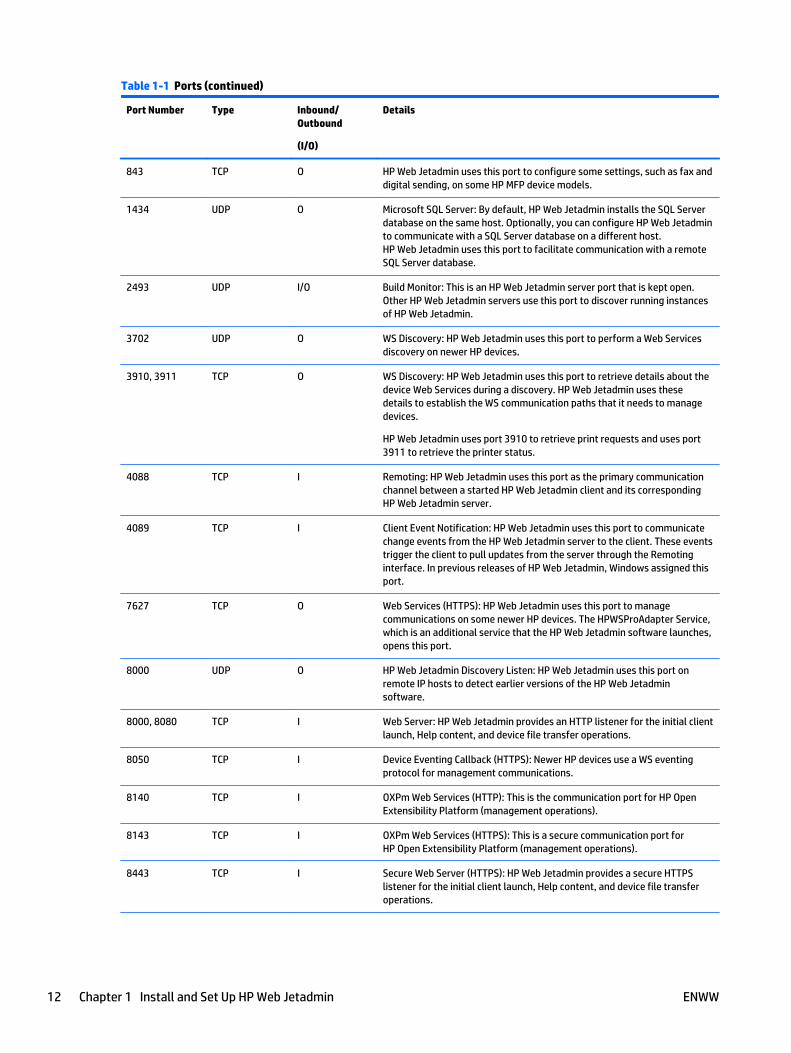
Table 1-1 Ports (continued)
Port Number Type Inbound/Outbound
(I/O)
Details
843 TCP O HP Web Jetadmin uses this port to configure some settings, such as fax anddigital sending, on some HP MFP device models.
1434 UDP O Microsoft SQL Server: By default, HP Web Jetadmin installs the SQL Serverdatabase on the same host. Optionally, you can configure HP Web Jetadminto communicate with a SQL Server database on a different host.HP Web Jetadmin uses this port to facilitate communication with a remoteSQL Server database.
2493 UDP I/O Build Monitor: This is an HP Web Jetadmin server port that is kept open.Other HP Web Jetadmin servers use this port to discover running instancesof HP Web Jetadmin.
3702 UDP O WS Discovery: HP Web Jetadmin uses this port to perform a Web Servicesdiscovery on newer HP devices.
3910, 3911 TCP O WS Discovery: HP Web Jetadmin uses this port to retrieve details about thedevice Web Services during a discovery. HP Web Jetadmin uses thesedetails to establish the WS communication paths that it needs to managedevices.
HP Web Jetadmin uses port 3910 to retrieve print requests and uses port3911 to retrieve the printer status.
4088 TCP I Remoting: HP Web Jetadmin uses this port as the primary communicationchannel between a started HP Web Jetadmin client and its correspondingHP Web Jetadmin server.
4089 TCP I Client Event Notification: HP Web Jetadmin uses this port to communicatechange events from the HP Web Jetadmin server to the client. These eventstrigger the client to pull updates from the server through the Remotinginterface. In previous releases of HP Web Jetadmin, Windows assigned thisport.
7627 TCP O Web Services (HTTPS): HP Web Jetadmin uses this port to managecommunications on some newer HP devices. The HPWSProAdapter Service,which is an additional service that the HP Web Jetadmin software launches,opens this port.
8000 UDP O HP Web Jetadmin Discovery Listen: HP Web Jetadmin uses this port onremote IP hosts to detect earlier versions of the HP Web Jetadminsoftware.
8000, 8080 TCP I Web Server: HP Web Jetadmin provides an HTTP listener for the initial clientlaunch, Help content, and device file transfer operations.
8050 TCP I Device Eventing Callback (HTTPS): Newer HP devices use a WS eventingprotocol for management communications.
8140 TCP I OXPm Web Services (HTTP): This is the communication port for HP OpenExtensibility Platform (management operations).
8143 TCP I OXPm Web Services (HTTPS): This is a secure communication port forHP Open Extensibility Platform (management operations).
8443 TCP I Secure Web Server (HTTPS): HP Web Jetadmin provides a secure HTTPSlistener for the initial client launch, Help content, and device file transferoperations.
12 Chapter 1 Install and Set Up HP Web Jetadmin ENWW
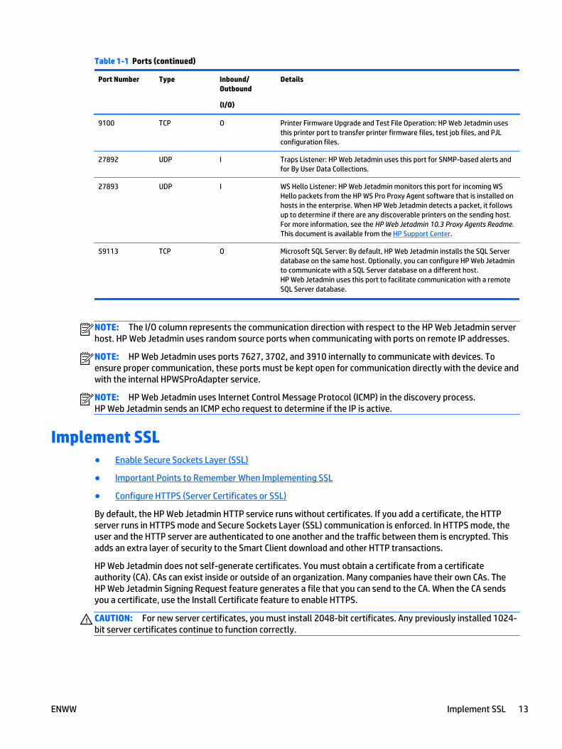
Table 1-1 Ports (continued)
Port Number Type Inbound/Outbound
(I/O)
Details
9100 TCP O Printer Firmware Upgrade and Test File Operation: HP Web Jetadmin usesthis printer port to transfer printer firmware files, test job files, and PJLconfiguration files.
27892 UDP I Traps Listener: HP Web Jetadmin uses this port for SNMP-based alerts andfor By User Data Collections.
27893 UDP I WS Hello Listener: HP Web Jetadmin monitors this port for incoming WSHello packets from the HP WS Pro Proxy Agent software that is installed onhosts in the enterprise. When HP Web Jetadmin detects a packet, it followsup to determine if there are any discoverable printers on the sending host.For more information, see the HP Web Jetadmin 10.3 Proxy Agents Readme.This document is available from the HP Support Center.
59113 TCP O Microsoft SQL Server: By default, HP Web Jetadmin installs the SQL Serverdatabase on the same host. Optionally, you can configure HP Web Jetadminto communicate with a SQL Server database on a different host.HP Web Jetadmin uses this port to facilitate communication with a remoteSQL Server database.
NOTE: The I/O column represents the communication direction with respect to the HP Web Jetadmin serverhost. HP Web Jetadmin uses random source ports when communicating with ports on remote IP addresses.
NOTE: HP Web Jetadmin uses ports 7627, 3702, and 3910 internally to communicate with devices. Toensure proper communication, these ports must be kept open for communication directly with the device andwith the internal HPWSProAdapter service.
NOTE: HP Web Jetadmin uses Internet Control Message Protocol (ICMP) in the discovery process.HP Web Jetadmin sends an ICMP echo request to determine if the IP is active.
Implement SSL● Enable Secure Sockets Layer (SSL)
● Important Points to Remember When Implementing SSL
● Configure HTTPS (Server Certificates or SSL)
By default, the HP Web Jetadmin HTTP service runs without certificates. If you add a certificate, the HTTPserver runs in HTTPS mode and Secure Sockets Layer (SSL) communication is enforced. In HTTPS mode, theuser and the HTTP server are authenticated to one another and the traffic between them is encrypted. Thisadds an extra layer of security to the Smart Client download and other HTTP transactions.
HP Web Jetadmin does not self-generate certificates. You must obtain a certificate from a certificateauthority (CA). CAs can exist inside or outside of an organization. Many companies have their own CAs. TheHP Web Jetadmin Signing Request feature generates a file that you can send to the CA. When the CA sendsyou a certificate, use the Install Certificate feature to enable HTTPS.
CAUTION: For new server certificates, you must install 2048-bit certificates. Any previously installed 1024-bit server certificates continue to function correctly.
ENWW Implement SSL 13
Enable Secure Sockets Layer (SSL)
HP Web Jetadmin administrators enable SSL by adding a certificate to the HP Web Jetadmin application. Thiscertificate forces the browser to use the more secure HTTPS protocol when a user accesses the client logonpage. The administrator must enable SSL from the console or host that runs the application by using theprocedure in Configure HTTPS (Server Certificates or SSL) on page 15. When a remote administratoraccesses Tools > Options > Shared > Network > HTTPS, a message appears stating that certificates can onlybe installed from an HP Web Jetadmin client that runs on the console or server that hosts HP Web Jetadmin.
In some environments, SSL is required when an HTTP interface or service is used for communication. In thesecases, SSL can be enabled and enforced by HP Web Jetadmin. SSL provides a high level of assuranceregarding the authentication and encryption of HTTP communication. That is, a user who requests access tothe HP Web Jetadmin Smart Client download can be reasonably assured that the system hostingHP Web Jetadmin is authentic and the communication between the two systems is encrypted so that itcannot be easily read by eavesdroppers.
The SSL protocol uses certificates to accommodate both authentication and encryption. HP Web Jetadmincan generate a signing request that can be used by a certificate authority (CA) to generate a certificate. UsingTools > Options > Shared > Network > HTTPS, the user can generate a Signing Request.
Once the request has been fulfilled by the CA, the certificate is ready to be installed on HP Web Jetadmin.Remember, you must be at the application console to use Tools > Options > Shared > Network > HTTPS. UseInstall Certificate to browse and upload the certificate file.
Once the certificate is installed, the HTTP service enforces SSL. Any browser contact with HP Web Jetadminshould indicate HTTPS on the URL when a certificate is installed. Using Remove Certificate uninstalls thecertificate and SSL is no longer enforced.
Important Points to Remember When Implementing SSL
Client communication with SSL enforced requires one or more of the following considerations.
● For new server certificates, you must install 2048-bit certificates. Any previously installed 1024-bitserver certificates continue to function correctly.
● When SSL has been implemented on HP Web Jetadmin with an internal certificate authority (CA), theCA’s authorizing certificate must be installed in the client browser. If this certificate is not installed inthe client browser the HP Web Jetadmin Smart Client page will fail to load up in SSL mode.
● Proxy servers tend to use the standard SSL port 443. If the HP Web Jetadmin Smart Client page is beingcalled through a proxy server, a redirect error may occur. This is due to the URL being redirected to 443rather than 8443 which is the port used by the HP Web Jetadmin SSL. The workaround for this is to placethe HP Web Jetadmin fully qualified domain name (FQDN) into the browsers exceptions list underTools > Internet Options > Connections > LAN Settings > Advanced. This causes the browser to pullHTTP and HTTPS content directly from the HP Web Jetadmin server.
NOTE: HP Web Jetadmin HTTP and HTTPS port numbers can be customized to something other than8000 and 8443.
● When you have implemented SSL on HP Web Jetadmin, a redirect occurs when the browser URL usesport 8000. Here is an example:
The known URL prior to SSL implementation is http://servername.domain.xxx:8000.
After SSL implementation, HP Web Jetadmin will redirect this to a new URL: https://servername.domain.xxx:8443.
The URLs shown here use FQDN. In most cases the certificate issued and installed in theHP Web Jetadmin SSL implementation will contain an FQDN for the host on which HP Web Jetadmin is
14 Chapter 1 Install and Set Up HP Web Jetadmin ENWW
installed. If a non FQDN is used in the browser, certificate failure will occur. As a general rule, form theHP Web Jetadmin URL with FQDN when HP Web Jetadmin is implemented with SSL.
To configure HTTPS, access Tools > Options > Shared > Network > HTTPS.
Configure HTTPS (Server Certificates or SSL)
NOTE: When using the HP Web Jetadmin client to install a certificate on a Vista host with UAC enabled, youmust launch the client from the installer (just after install is finished and from the checkbox that enablesclient launch) or from an IE that was Run as Administrator.
CAUTION: For new server certificates, you must install 2048-bit certificates. Any previously installed 1024-bit server certificates continue to function correctly.
1. To configure HTTPS, access Tools > Options > Shared > Network > HTTPS.
2. To associate a certificate with the HP Web Jetadmin server and enable HTTPS, select Install Certificate.
To remove the installed certificate from the server and disable HTTPS, select Remove Certificate.
To generate a certificate request that can be sent to a signing authority to generate a certificate thatcan be installed to enable HTTPS, select Signing Request.
3. To save these settings and continue setting other options, click Apply. Then click the next option toconfigure in the left menu bar. To save these settings and close this window, click OK.
Use a Separate Instance of Microsoft SQL ServerBy default, HP Web Jetadmin installs and uses a database that runs under Microsoft SQL Server Express. Youcan configure an existing installation of HP Web Jetadmin to use the full version of SQL Server instead of SQLServer Express. However, HP does not support or test HP Web Jetadmin installations with SQL Serverdatabases other than the version listed in Database on page 5 and, therefore, cannot guarantee the results.
For more information about configuring HP Web Jetadmin to use a separate Microsoft SQL instance, see theUsing Microsoft SQL Server with HP Web Jetadmin white paper. This white paper is available from the HP Support Center.
Deploy the Smart Client● Start a Smart Client Session
● Configure HP Web Jetadmin to Bind to a Specific NIC
● Configure the Event Notification Port
● Configure the Firewall Software
HP Web Jetadmin uses the Microsoft ClickOnce Smart Client technology. This technology runs aMicrosoft .NET Framework application by automatically downloading and launching the application through aWeb browser. The Smart Client application runs as a local .NET Framework application on the host andcommunicates with the HP Web Jetadmin service via .NET Remoting. After the Smart Client applicationlaunches, the Web browser is no longer required. Although HP Web Jetadmin also uses the Web browser foronline Help and proactive Product Update notifications, the HP Web Jetadmin client application runs locallyon the computer.
The default HTTP port is 8000. The default HTTPS port is 8443. The HP Web Jetadmin installer builds ashortcut on the installation host that uses a URL in the format http://<hostname>:8000. You can also use thisURL to access HP Web Jetadmin remotely from anywhere on the company's intranet or WAN.
ENWW Use a Separate Instance of Microsoft SQL Server 15
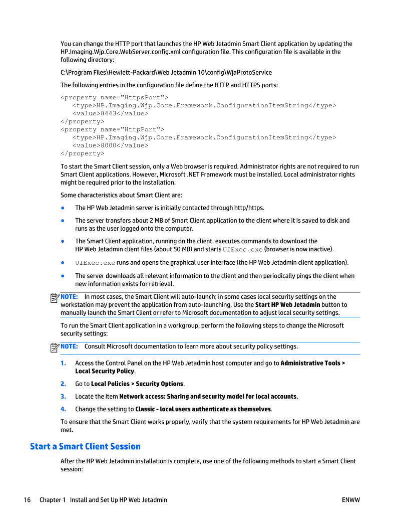
You can change the HTTP port that launches the HP Web Jetadmin Smart Client application by updating theHP.Imaging.Wjp.Core.WebServer.config.xml configuration file. This configuration file is available in thefollowing directory:
C:\Program Files\Hewlett-Packard\Web Jetadmin 10\config\WjaProtoService
The following entries in the configuration file define the HTTP and HTTPS ports:
<property name="HttpsPort"> <type>HP.Imaging.Wjp.Core.Framework.ConfigurationItemString</type> <value>8443</value></property><property name="HttpPort"> <type>HP.Imaging.Wjp.Core.Framework.ConfigurationItemString</type> <value>8000</value></property>
To start the Smart Client session, only a Web browser is required. Administrator rights are not required to runSmart Client applications. However, Microsoft .NET Framework must be installed. Local administrator rightsmight be required prior to the installation.
Some characteristics about Smart Client are:
● The HP Web Jetadmin server is initially contacted through http/https.
● The server transfers about 2 MB of Smart Client application to the client where it is saved to disk andruns as the user logged onto the computer.
● The Smart Client application, running on the client, executes commands to download theHP Web Jetadmin client files (about 50 MB) and starts UIExec.exe (browser is now inactive).
● UIExec.exe runs and opens the graphical user interface (the HP Web Jetadmin client application).
● The server downloads all relevant information to the client and then periodically pings the client whennew information exists for retrieval.
NOTE: In most cases, the Smart Client will auto-launch; in some cases local security settings on theworkstation may prevent the application from auto-launching. Use the Start HP Web Jetadmin button tomanually launch the Smart Client or refer to Microsoft documentation to adjust local security settings.
To run the Smart Client application in a workgroup, perform the following steps to change the Microsoftsecurity settings:
NOTE: Consult Microsoft documentation to learn more about security policy settings.
1. Access the Control Panel on the HP Web Jetadmin host computer and go to Administrative Tools >Local Security Policy.
2. Go to Local Policies > Security Options.
3. Locate the item Network access: Sharing and security model for local accounts.
4. Change the setting to Classic - local users authenticate as themselves.
To ensure that the Smart Client works properly, verify that the system requirements for HP Web Jetadmin aremet.
Start a Smart Client Session
After the HP Web Jetadmin installation is complete, use one of the following methods to start a Smart Clientsession:
16 Chapter 1 Install and Set Up HP Web Jetadmin ENWW
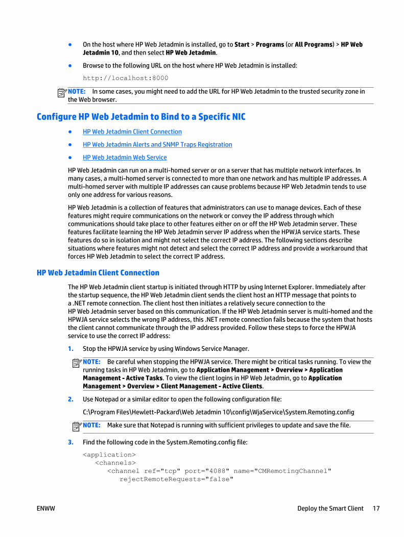
● On the host where HP Web Jetadmin is installed, go to Start > Programs (or All Programs) > HP WebJetadmin 10, and then select HP Web Jetadmin.
● Browse to the following URL on the host where HP Web Jetadmin is installed:
http://localhost:8000
NOTE: In some cases, you might need to add the URL for HP Web Jetadmin to the trusted security zone inthe Web browser.
Configure HP Web Jetadmin to Bind to a Specific NIC
● HP Web Jetadmin Client Connection
● HP Web Jetadmin Alerts and SNMP Traps Registration
● HP Web Jetadmin Web Service
HP Web Jetadmin can run on a multi-homed server or on a server that has multiple network interfaces. Inmany cases, a multi-homed server is connected to more than one network and has multiple IP addresses. Amulti-homed server with multiple IP addresses can cause problems because HP Web Jetadmin tends to useonly one address for various reasons.
HP Web Jetadmin is a collection of features that administrators can use to manage devices. Each of thesefeatures might require communications on the network or convey the IP address through whichcommunications should take place to other features either on or off the HP Web Jetadmin server. Thesefeatures facilitate learning the HP Web Jetadmin server IP address when the HPWJA service starts. Thesefeatures do so in isolation and might not select the correct IP address. The following sections describesituations where features might not detect and select the correct IP address and provide a workaround thatforces HP Web Jetadmin to select the correct IP address.
HP Web Jetadmin Client Connection
The HP Web Jetadmin client startup is initiated through HTTP by using Internet Explorer. Immediately afterthe startup sequence, the HP Web Jetadmin client sends the client host an HTTP message that points toa .NET remote connection. The client host then initiates a relatively secure connection to theHP Web Jetadmin server based on this communication. If the HP Web Jetadmin server is multi-homed and theHPWJA service selects the wrong IP address, this .NET remote connection fails because the system that hoststhe client cannot communicate through the IP address provided. Follow these steps to force the HPWJAservice to use the correct IP address:
1. Stop the HPWJA service by using Windows Service Manager.
NOTE: Be careful when stopping the HPWJA service. There might be critical tasks running. To view therunning tasks in HP Web Jetadmin, go to Application Management > Overview > ApplicationManagement - Active Tasks. To view the client logins in HP Web Jetadmin, go to ApplicationManagement > Overview > Client Management - Active Clients.
2. Use Notepad or a similar editor to open the following configuration file:
C:\Program Files\Hewlett-Packard\Web Jetadmin 10\config\WjaService\System.Remoting.config
NOTE: Make sure that Notepad is running with sufficient privileges to update and save the file.
3. Find the following code in the System.Remoting.config file:
<application> <channels> <channel ref="tcp" port="4088" name="CMRemotingChannel" rejectRemoteRequests="false"
ENWW Deploy the Smart Client 17
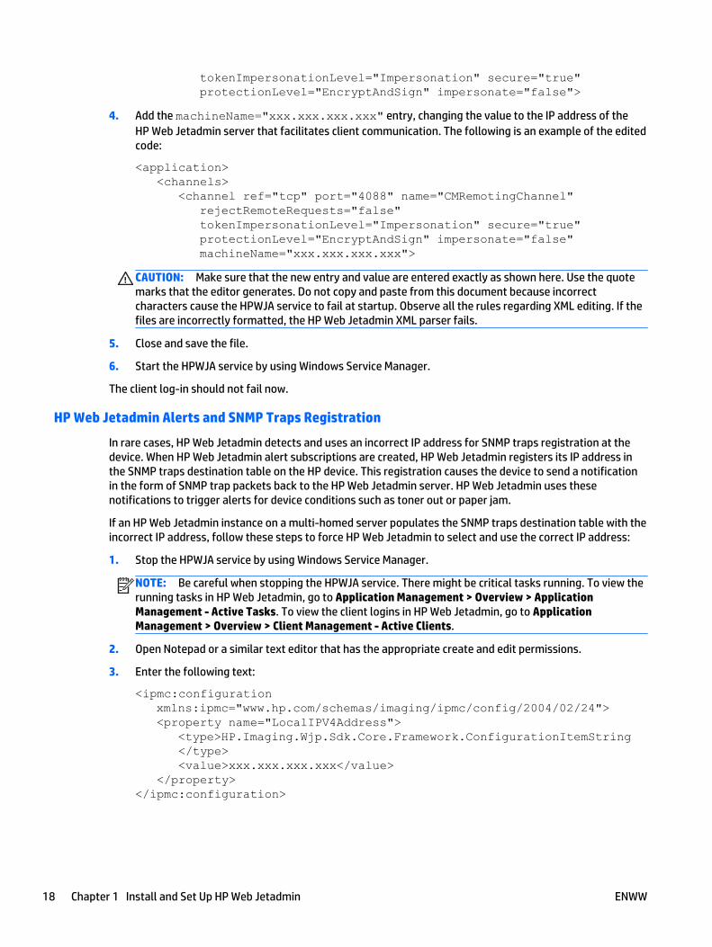
tokenImpersonationLevel="Impersonation" secure="true" protectionLevel="EncryptAndSign" impersonate="false">
4. Add the machineName="xxx.xxx.xxx.xxx" entry, changing the value to the IP address of theHP Web Jetadmin server that facilitates client communication. The following is an example of the editedcode:
<application> <channels> <channel ref="tcp" port="4088" name="CMRemotingChannel" rejectRemoteRequests="false" tokenImpersonationLevel="Impersonation" secure="true" protectionLevel="EncryptAndSign" impersonate="false" machineName="xxx.xxx.xxx.xxx">
CAUTION: Make sure that the new entry and value are entered exactly as shown here. Use the quotemarks that the editor generates. Do not copy and paste from this document because incorrectcharacters cause the HPWJA service to fail at startup. Observe all the rules regarding XML editing. If thefiles are incorrectly formatted, the HP Web Jetadmin XML parser fails.
5. Close and save the file.
6. Start the HPWJA service by using Windows Service Manager.
The client log-in should not fail now.
HP Web Jetadmin Alerts and SNMP Traps Registration
In rare cases, HP Web Jetadmin detects and uses an incorrect IP address for SNMP traps registration at thedevice. When HP Web Jetadmin alert subscriptions are created, HP Web Jetadmin registers its IP address inthe SNMP traps destination table on the HP device. This registration causes the device to send a notificationin the form of SNMP trap packets back to the HP Web Jetadmin server. HP Web Jetadmin uses thesenotifications to trigger alerts for device conditions such as toner out or paper jam.
If an HP Web Jetadmin instance on a multi-homed server populates the SNMP traps destination table with theincorrect IP address, follow these steps to force HP Web Jetadmin to select and use the correct IP address:
1. Stop the HPWJA service by using Windows Service Manager.
NOTE: Be careful when stopping the HPWJA service. There might be critical tasks running. To view therunning tasks in HP Web Jetadmin, go to Application Management > Overview > ApplicationManagement - Active Tasks. To view the client logins in HP Web Jetadmin, go to ApplicationManagement > Overview > Client Management - Active Clients.
2. Open Notepad or a similar text editor that has the appropriate create and edit permissions.
3. Enter the following text:
<ipmc:configuration xmlns:ipmc="www.hp.com/schemas/imaging/ipmc/config/2004/02/24"> <property name="LocalIPV4Address"> <type>HP.Imaging.Wjp.Sdk.Core.Framework.ConfigurationItemString </type> <value>xxx.xxx.xxx.xxx</value> </property></ipmc:configuration>
18 Chapter 1 Install and Set Up HP Web Jetadmin ENWW
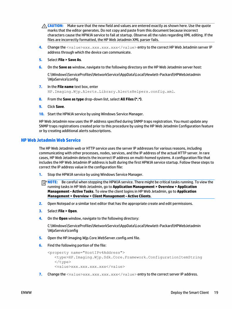
CAUTION: Make sure that the new field and values are entered exactly as shown here. Use the quotemarks that the editor generates. Do not copy and paste from this document because incorrectcharacters cause the HPWJA service to fail at startup. Observe all the rules regarding XML editing. If thefiles are incorrectly formatted, the HP Web Jetadmin XML parser fails.
4. Change the <value>xxx.xxx.xxx.xxx</value> entry to the correct HP Web Jetadmin server IPaddress through which the device can communicate.
5. Select File > Save As.
6. On the Save as window, navigate to the following directory on the HP Web Jetadmin server host:
C:\Windows\ServiceProfiles\NetworkService\AppData\Local\Hewlett-Packard\HPWebJetadmin\WjaService\config
7. In the File name text box, enterHP.Imaging.Wjp.Alerts.Library.AlertsHelpers.config.xml.
8. From the Save as type drop-down list, select All Files (*.*).
9. Click Save.
10. Start the HPWJA service by using Windows Service Manager.
HP Web Jetadmin now uses the IP address specified during SNMP traps registration. You must update anySNMP traps registrations created prior to this procedure by using the HP Web Jetadmin Configuration featureor by creating additional alerts subscriptions.
HP Web Jetadmin Web Service
The HP Web Jetadmin web or HTTP service uses the server IP addresses for various reasons, includingcommunicating with other processes, nodes, services, and the IP address of the actual HTTP server. In rarecases, HP Web Jetadmin detects the incorrect IP address on multi-homed systems. A configuration file thatincludes the HP Web Jetadmin IP address is built during the first HPWJA service startup. Follow these steps tocorrect the IP address value in the configuration file:
1. Stop the HPWJA service by using Windows Service Manager.
NOTE: Be careful when stopping the HPWJA service. There might be critical tasks running. To view therunning tasks in HP Web Jetadmin, go to Application Management > Overview > ApplicationManagement - Active Tasks. To view the client logins in HP Web Jetadmin, go to ApplicationManagement > Overview > Client Management - Active Clients.
2. Open Notepad or a similar text editor that has the appropriate create and edit permissions.
3. Select File > Open.
4. On the Open window, navigate to the following directory:
C:\Windows\ServiceProfiles\NetworkService\AppData\Local\Hewlett-Packard\HPWebJetadmin\WjaService\config
5. Open the HP.Imaging.Wjp.Core.WebServer.config.xml file.
6. Find the following portion of the file:
<property name="HostIPv4Address"> <type>HP.Imaging.Wjp.Sdk.Core.Framework.ConfigurationItemString </type> <value>xxx.xxx.xxx.xxx</value>
7. Change the <value>xxx.xxx.xxx.xxx</value> entry to the correct server IP address.
ENWW Deploy the Smart Client 19
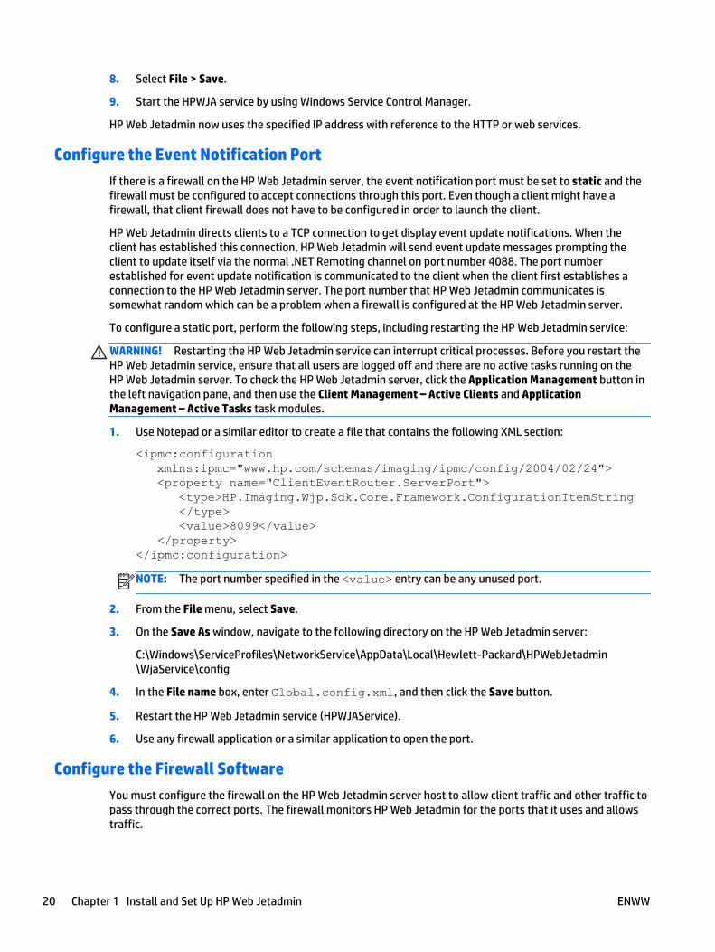
8. Select File > Save.
9. Start the HPWJA service by using Windows Service Control Manager.
HP Web Jetadmin now uses the specified IP address with reference to the HTTP or web services.
Configure the Event Notification Port
If there is a firewall on the HP Web Jetadmin server, the event notification port must be set to static and thefirewall must be configured to accept connections through this port. Even though a client might have afirewall, that client firewall does not have to be configured in order to launch the client.
HP Web Jetadmin directs clients to a TCP connection to get display event update notifications. When theclient has established this connection, HP Web Jetadmin will send event update messages prompting theclient to update itself via the normal .NET Remoting channel on port number 4088. The port numberestablished for event update notification is communicated to the client when the client first establishes aconnection to the HP Web Jetadmin server. The port number that HP Web Jetadmin communicates issomewhat random which can be a problem when a firewall is configured at the HP Web Jetadmin server.
To configure a static port, perform the following steps, including restarting the HP Web Jetadmin service:
WARNING! Restarting the HP Web Jetadmin service can interrupt critical processes. Before you restart theHP Web Jetadmin service, ensure that all users are logged off and there are no active tasks running on theHP Web Jetadmin server. To check the HP Web Jetadmin server, click the Application Management button inthe left navigation pane, and then use the Client Management – Active Clients and ApplicationManagement – Active Tasks task modules.
1. Use Notepad or a similar editor to create a file that contains the following XML section:
<ipmc:configuration xmlns:ipmc="www.hp.com/schemas/imaging/ipmc/config/2004/02/24"> <property name="ClientEventRouter.ServerPort"> <type>HP.Imaging.Wjp.Sdk.Core.Framework.ConfigurationItemString </type> <value>8099</value> </property></ipmc:configuration>
NOTE: The port number specified in the <value> entry can be any unused port.
2. From the File menu, select Save.
3. On the Save As window, navigate to the following directory on the HP Web Jetadmin server:
C:\Windows\ServiceProfiles\NetworkService\AppData\Local\Hewlett-Packard\HPWebJetadmin\WjaService\config
4. In the File name box, enter Global.config.xml, and then click the Save button.
5. Restart the HP Web Jetadmin service (HPWJAService).
6. Use any firewall application or a similar application to open the port.
Configure the Firewall Software
You must configure the firewall on the HP Web Jetadmin server host to allow client traffic and other traffic topass through the correct ports. The firewall monitors HP Web Jetadmin for the ports that it uses and allowstraffic.
20 Chapter 1 Install and Set Up HP Web Jetadmin ENWW
In some firewall applications, such as Microsoft Firewall, you can specify a program or executable file as afirewall exception. In these cases, you can define the following file as an exception:
C:\Program Files\Hewlett-Packard\Web Jetadmin 10\bin\HPWJAService.exe
The firewall on the client system does not require any special consideration because the client applicationdoes not listen to a specific port.
Restart the HP Web Jetadmin Service ManuallyIt may be necessary to stop and restart the HP Web Jetadmin service. An example of this would be when anetwork is switched from hard-wired to wireless. Once the network is switched, HP Web Jetadmin must berestarted in order for the application to realize the change.
WARNING! Restarting HP Web Jetadmin services may interrupt background tasks and user sessions. Alwayscheck the application before restarting.
To script the stop of all HP Web Jetadmin services, use these command strings in this order:
● Net stop HPWSProAdapter
● Net stop HPWJAService
● Net stop mssql$HPWJA
To script the start of all HP Web Jetadmin services, use these command strings in this order:
● Net start mssql$HPWJA
● Net start HPWJAService
● Net start HPWSProAdapter
1. Uninstall HP Web Jetadmin.
2. Use Windows Service Manager to set the older HP Web Jetadmin service (listed as HP Web Jetadmin inthe Services MMC) to activate and to also start the service.
Back Up and Restore HP Web JetadminScripts for backing up and restoring HP Web Jetadmin are available. These scripts provide examples of therecommended method for backing up and restoring the HP Web Jetadmin settings and data, including theMicrosoft SQL Server database. The WJABackupRestoreInstructions_<language_code>.txt file providesinstructions for running the scripts. The scripts and instructions are available in the following directory:
C:\Program Files\Hewlett-Packard\Web Jetadmin 10\WJABackupRestore
Upgrade HP Web JetadminIMPORTANT: You must run a backup of the current HP Web Jetadmin installation before you begin anupgrade. Read the information in the WJABackupRestoreInstructions_<language_code>.txt file that islocated in the following directory on the HP Web Jetadmin server:
C:\Program Files\Hewlett-Packard\Web Jetadmin 10\WJABackupRestore
In HP Web Jetadmin, go to Help > About, and then write down the current version as 10.3.nnnnn, wherennnnn is the build number. This is the version of the installer you must have if a recovery is required.
ENWW Restart the HP Web Jetadmin Service Manually 21
Before you begin an upgrade, go to Application Management > Overview > Application Management –Active Tasks, and then check for any paused or pending tasks. You must stop or resolve these tasks beforeyou run the installer.
To upgrade HP Web Jetadmin, obtain the HP Web Jetadmin installation executable from www.hp.com/go/webjetadmin. Then run the executable on the system that hosts HP Web Jetadmin.
Uninstall HP Web Jetadmin● Uninstall HP Web Jetadmin from the Command Line
When you uninstall HP Web Jetadmin, the Microsoft SQL Server Express Edition instance of theHP Web Jetadmin database is also removed. You can restore the HP Web Jetadmin database if you ran theappropriate backup procedures and stored the backup files in a secure location.
To uninstall HP Web Jetadmin, perform the following steps:
1. Go to Start > Control Panel > Uninstall a program.
2. Right-click HP Web Jetadmin 10.3, and then select Change. The HP Web Jetadmin 10.3 - InstallShieldWizard starts.
3. Click the Next button.
4. Select the Remove option, and then click the Next button.
5. Follow the instructions in the wizard.
6. Review the MSI<xxxxx>.LOG file, where <xxxxx> is a randomly generated string. The log file is availablein the following directory:
C:\Users\<username>\AppData\Local\Temp
Uninstall HP Web Jetadmin from the Command Line
You can uninstall HP Web Jetadmin from the command line. For instructions, see the UninstallHP Web Jetadmin from the Command Line white paper. This white paper is available from the HP SupportCenter.
Manage LicensesThere are some features for HP Web Jetadmin that require a license. After you obtain the license for afeature, you must install the license to enable the functionality.
To manage the licenses, perform the following steps:
1. Go to Start > All Programs > HP Web Jetadmin 10, and then select HP Web Jetadmin License Manager.
2. To install a license, perform the following steps:
a. Click the Add button.
b. On the Enter License window, enter the license key, and then click the Apply button.
3. To delete a license, select the license from the list, and then click the Remove button.
4. To refresh the list of licenses, click the Refresh button.
5. Click the Exit button.
6. Restart the HP Web Jetadmin service (HPWJA Service).
22 Chapter 1 Install and Set Up HP Web Jetadmin ENWW

2 Introduction to HP Web Jetadmin
● Product Support
● Getting Around in HP Web Jetadmin
● The HP Web Jetadmin Server
● The HP Web Jetadmin Client
● Shared Configuration Options for all Views
● Application Management Configuration Options
● Device Management Configuration Options
HP Web Jetadmin increases business productivity by helping you proactively address potential printingproblems, automatically configure peripheral drivers, and update firmware. HP Web Jetadmin provides all ofthe peripheral management capabilities you need in one easy-to-use Web browser interface. It is a is a freeutility that you can download from www.hp.com/go/webjetadmin.
Product Support● Print the HP Web Jetadmin Guides
● Online Help
● Feedback about HP Web Jetadmin
● Technical Support
This section provides information about obtaining support for HP Web Jetadmin.
Print the HP Web Jetadmin Guides
If you need to print the HP Web Jetadmin 10.3 Installation and Setup Guide and the HP Web Jetadmin 10.3User Guide, PDFs are available from the HP Support Center.
To view PDF files, Adobe Acrobat Reader must be installed on your computer. To download the latest AdobeAcrobat Reader, go to www.adobe.com/products/acrobat/readstep2.html.
Online Help
The HP Web Jetadmin online Help provides detailed information about using the software to configure andmanage devices on the network. Use the Contents, Index, and Search tabs to navigate the online Help.
Each page in HP Web Jetadmin has a help icon (?) on the content toolbar. When you click the help icon andthen click somewhere on the user interface, HP Web Jetadmin displays the context-sensitive help for thatspecific portion of the user interface.
NOTE: To access external links, the browser must have access to the Internet. If you are behind an Internetfirewall, you might need to configure proxy servers. Contact the network administrator to determine theappropriate settings for the browser.
ENWW Product Support 23
Feedback about HP Web Jetadmin
You can send comments and suggestions about HP Web Jetadmin to HP. To send an email to HP, go to Help >Feedback. You will receive an automatic reply that indicates HP has received your email. If HP needs moreinformation about your feedback, a representative will contact you.
NOTE: HP Web Jetadmin includes the comments, browser version, HP Web Jetadmin version, Web serverversion, operating system version, name of the directory where HP Web Jetadmin is installed, and memoryusage in the email.
HP considers your comments and suggestions, but HP does not answer questions through the Feedbackfeature. If you have questions about HP Web Jetadmin, go to www.hp.com/go/webjetadmin.
Technical Support
HP maintains an extensive Web presence to provide information and assistance. To obtain technical supportfor HP Web Jetadmin, use the following links:
● www.hp.com/go/webjetadmin
Provides access to Premium Support, Consulting Services, and a variety of self-help information, suchas FAQs, support documentation, and white papers.
● www.support.hp.com
Provides access to 24/7 online support for your country/region.
Getting Around in HP Web Jetadmin● Application Views in HP Web Jetadmin
● Top Menu Bar Features
● Status Bar Features
● Page Layout in HP Web Jetadmin
● Wizards
● Other Features
The user interface for HP Web Jetadmin is designed to be efficient and intuitive, limiting the number of stepsrequired to complete a task and streamlining software operation.
Application Views in HP Web Jetadmin
HP Web Jetadmin can be separated into three views accessible through the lower portion of the leftnavigation pane:
● Device Management on page 70 for managing all device-related functions.
● Print Management on page 259 for managing print queues and drivers on remote servers andworkstations.
● Application Management on page 269 for managing application functionality such as users and roles,security, and software updates.
Top Menu Bar Features
● Preferences
24 Chapter 2 Introduction to HP Web Jetadmin ENWW
● Device Filters
● Device Identification
● Application Logging
The top menu bar is always present and changes depending on the application view, presence of plug-ins,and the version of HP Web Jetadmin. This allows you to use functionality without having to change to adifferent view.
Across the top menu bar are four choices:
● File: Add new groups, alerts, and configuration templates; print, and exit HP Web Jetadmin.
◦ New: Create groups (Create a New Device Group on page 114), alerts templates (Create AlertSubscription Templates on page 185), and configuration templates (Create a ConfigurationTemplate on page 171).
◦ Print: Print the device list (Printing Device Lists on page 105).
◦ Exit: Exit HP Web Jetadmin.
● View: Customize interface settings based on the user’s credentials:
◦ Column Layouts: Create custom views by identifying columns displayed for any device list(Columns for Device Lists on page 93).
◦ Filters: Create and manage filters using the Filter Manager and Filter Editor. (Filters and DeviceLists on page 97).
◦ Refresh device selection: Retrieve data directly from the selected device. It is useful if yoususpect the data displayed for the device may be out of date. This feature is available on a devicelist page for single device views.
◦ Task Module Docking Area and the Map Docking Area: Manage the task modules and maps youwant to always be displayed (Docking Task Modules and Maps on page 28).
◦ Preferences: Set preferences for data to be displayed in device lists (Device Lists on page 91).See Preferences on page 26.
● Tools: Manage global settings including:
◦ Export devices: Starts the Export Devices wizard to export device attributes to a file and thenstore them on a disk or send them via email through SMTP (Exporting Device Data on page 102).
◦ Device Discovery: Starts the Device Discovery wizard to locate network and PC connected devices(Discover Devices (the Device Discovery Wizard) on page 149).
◦ Application Log: View a log of all transactions that contain information that includes the user,what the activity was and its details, and when the transaction occurred (Application Loggingon page 26).
◦ Data Synchronization: Synchronize data between multiple installations of HP Web Jetadmin. Formore information, see Data Synchronization on page 290).
◦ Options: Manage configuration settings for each view (Device Management Options on page 72and Application Management Configuration Options on page 50).
● Help: See online help for this product (Online Help on page 23).
ENWW Getting Around in HP Web Jetadmin 25
Preferences
Preferences for lists (in Device Lists on page 91 and Groups on page 109) lets you manage data displayedin those lists. The top menu bar changes depending on the application view, presence of plug-ins, and theversion of HP Web Jetadmin.
Device Filters
You can select which device lists or filters are displayed in the left navigation pane.
To configure device filters, perform the following steps:
1. From the top menu bar, select View > Preferences > Device Filters. The Preferences page is displayedwith fields for device filters.
2. To display device filters in the left navigation pane under All Devices, move the filters from Availablefilters to Selected filters.
To remove filters from the left navigation pane, select them in Selected filters and move them toAvailable filters.
3. To save these settings and continue setting other options, click Apply. Then click the next option toconfigure in the left menu bar. To save these settings and close this window, click OK.
Device Identification
Individual users can customize device tools to reflect only the device information that is most important tothem. Space on device lists can be limited, so you should carefully choose the columns to be displayed. Youcan select columns to identify the devices on the Select Devices page, on the device list pages in Device Lists(Device Lists on page 91) and in Device Groups (Groups on page 109) and in the Status tab (Status Tabon page 73).
To configure how devices are identified, perform the following steps:
1. From the top menu bar, select View > Preferences > Device Identification. The Preferences page isdisplayed with fields for device identification.
2. To display fields as columns on device lists throughout HP Web Jetadmin, move them from Availablefields to Selected fields.
To remove columns from device lists, move the fields from Selected Fields to Available Fields.
3. To save these settings and continue setting other options, click Apply. Then click the next option toconfigure in the left menu bar. To save these settings and close this window, click OK.
Application Logging
In HP Web Jetadmin, you can view a log of all transactions that have occurred. The log includes the user, thetransaction and its details, and when the transaction occurred. To set the time for application log data to besaved, see Configure the Settings for the Application Log on page 51.
At the top of the log page, you can display log entries that occurred during a start and ending time frame ifdesired. You can also refresh the log.
Columns on the Application Log include:
● Action Details: describes the action that occurred.
● Details: shows details about the action.
● Triggered by: how the task was triggered, such as User, Group Policy, or Scheduled Template.
26 Chapter 2 Introduction to HP Web Jetadmin ENWW

● User: the user who started the task.
● Time: start time of the task. If no time is displayed, the task was just executed.
Follow these steps: to view the Application Log.
1. From the top menu bar, select Tools > Application Log. The Application Log is displayed.
2. Perform one or more of the following actions:
● To re-sort the Application Log, click on any column header.
● To change the length of time to save log entries and/or to clear the log, click Edit Log Settings(see Configure the Settings for the Application Log on page 51).
● To clear the log, click Clear Log.
● To access online help for this product, click Help (Online Help on page 23).
Status Bar Features
The status bar spans the bottom of the page and includes information about:
● Activity indicator: indicates the status of HP Web Jetadmin. If HP Web Jetadmin is processing abackground activity (for example, refreshing a device or getting updated data about a device), it isdisplayed in this area (the area includes the icon/menu and the status message). If more than oneactivity is underway, the user can see the list of what is happening by clicking on the activity indicator.They can select an entry from the list to see the status message associated with that activity. If a newactivity starts it will change what is shown (otherwise the selected activity message will continue toshow until the activity completes).
If multiple activities are in progress, you can see the list of all of those activities by clicking on theActivity indicator. You can select an entry from the list to see the status message associated with thatactivity.
● Device counts: when in device lists, this indicates the device you have highlighted and a count of alldevices in the displayed list.
● Layout: when in device lists, displays the type of layout being shown.
● Filter: when in device lists, states whether or not filters are in use.
● Map: identifies the item on the map. This information is included in the activity/status message areaand is not a separate area on the status bar.
Page Layout in HP Web Jetadmin
● Left Navigation Pane
● Task Modules
● Docking Task Modules and Maps
● Workspace
Each page in HP Web Jetadmin has the following features:
ENWW Getting Around in HP Web Jetadmin 27

● A left navigation pane that lists all functions for each separate view (Left Navigation Paneon page 28).
● An area on the right that displays content or task modules providing access to related features or tasks(Task Modules on page 28).
● A work space that changes depending on the view and the feature selected (Workspace on page 29).
You can resize columns for most lists by clicking and dragging the column headers.
Left Navigation Pane
HP Web Jetadmin has a navigation pane on the left side of the user interface that displays a tree for thecurrent view (Device Management, Print Management, or Application Management). The tree provides anorganized display of the functionality of the view. The Device Management view contains most of thefunctionality of HP Web Jetadmin and, therefore, has the most complex tree.
Many parts of the navigation tree have right-click functionality. An example of this is Discovery on page 123,where you can select an item from the Discover devices right-click menu.
Other parts of the tree, such as Device Groups (Groups on page 109), have drag-and-drop functionalityenabled. Devices can be selected in device lists within the workspace and dragged into Device Groups. Theselected devices are added as group members. Many top-level nodes can invoke summary functionality inthe workspace. By selecting a top-level node, such as Alerts, the workspace in the right-hand portion of theinterface contains a summary of the Alerts features. The task modules that are specific to a feature (such asAlerts) are then displayed in the work space. You can alter the feature summary by selecting or deselectingthe task modules that are important to you. (See Task Modules on page 28.)
Task Modules
Task modules are flexible blocks of specific or targeted functionality designed to help a you perform a task orobtain feature information. You can find task modules in many of the workspace pages or in the docking area(see Docking Task Modules and Maps on page 28). In either case, you can enable or disable task modules ona per-user basis. You can hide or display task modules, and you can move them within the content area.
A Current Task task module is initially included in the task module docking for each section. For example, inDevice Groups, the Current Tasks - Device Groups task module lists all tasks within Groups.
Docking Task Modules and Maps
The docking feature in HP Web Jetadmin enables you to dock task modules and maps. You can:
● Specify a map or a user-specific collection of task modules in HP Web Jetadmin to be docked.
● View the collection of task modules regardless of the current focus of the application.
● Undock the maps or collection of task modules to maximize application space.
● Dock maps or task modules to any one of four sides of the work space.
● Hide maps or the collection of task modules beneath a tabbed control that enables access at any time.
● View a Current Tasks task module, which changes depending on the focus (context) of the application.
To display the Task Module docking area, click View > Task Modules > Task Module docking area. To displaythe Map docking area, click View > Device Modules > Map. The Map menu item is available when you haveselected a group; the group does not have to have to a map associated with it. The Map module is visible ifthe Map menu item has been selected to show the module and if the selected group has a map associatedwith it. Note here that the map module may not be visible even if it is “displayed” because it is only visiblewhen you are on a group that has a map attached to it.
28 Chapter 2 Introduction to HP Web Jetadmin ENWW
Workspace
The large area on the right side of the navigation tree is the HP Web Jetadmin workspace. This area changesdepending on the View and Navigation tree elements selected. In many cases, the focus of this area can be asummary of a feature space. You can obtain this summary by selecting any top-level element within thenavigation tree. Elements with the + symbol next to them are top-level elements that invoke a summaryfocus. An exception to this is the All Devices list. When All Devices is selected in the left navigation pane, thedevice list is displayed in the workspace. The workspace can also reflect specific feature functionality.Whenever a sub-level element (generally one that has no + symbol next to it) is selected, the workspacereflects specific functionality. For an example, see Discovery History on page 153.
Wizards
● Need Info Wizard
Wizards provide a collection of steps in the required order for a user to accomplish a task successfully. Everywizard is launched in a window separate from the main application by using many different controls includingright-click menu items and task modules. Many of the wizards in HP Web Jetadmin are launched frommultiple controls in different parts of the application. An example of a wizard is Create Group (Create a NewDevice Group on page 114). After your start the wizard, you are prompted for the group type, the groupname, and the group members; after you identify that information, you can continue with the displayed stepsuntil the task is successfully completed. Confirmation and results pages provide both a safeguard andadditional details about the task.
Need Info Wizard
The Need Info wizard is displayed when you try to perform a device configuration but provide incorrectsensitive configuration information.
Some configuration items require additional information, such as an existing password, before setting thenew configuration. If you fail to enter this required information correctly, the Need Info wizard is displayed,providing an opportunity to enter the correct information. The wizard displays one or more devices on theleft, and prompts you for the required information on the right. You can only change the requiredinformation. All other information remains the same as originally entered.
For each device and each set of required information, you must click either Set or Skip to complete thewizard. You can select one or more devices in the list, enter the required information, and click Set. If you donot know the existing passwords or required information, you can click Skip. If you click Skip, thatconfiguration item will not be set on that device.
When you click Finish, HP Web Jetadmin tries to complete the device configuration again. If additionalinformation is required, the Need Info wizard is displayed again.
Other Features
● Drag-and-drop: You can drag-and-drop various items (for example, devices) onto functionality(reports, groups, and more) to save time and increase accuracy.
● Errors Encountered within HP Web Jetadmin: If the user interface has an error or cannot understandthe input, it displays “error on page”. You can hover the mouse over the error icon to see informationabout the problem that exists on that page.
● Identification of the HP Web Jetadmin Server: The title bar on the HP Web Jetadmin client windowalways indicates the name of the computer system where HP Web Jetadmin is installed.
● Determining the Software Version: By using Help > About, an HP Web Jetadmin logo page can belaunched. This contains the exact revision of the software in the xx.x.xxxxx format which representsMajorApplicationVersion.MinorApplicationVersion.Buildnumber number.
ENWW Getting Around in HP Web Jetadmin 29
● Client Performance: HP Web Jetadmin provides a significant improvement in application performanceover earlier versions. The client application performs many tasks locally to reduce traffic to the server,thus improving client performance. HP Web Jetadmin leverages the client application in many ways tomaximize performance.
◦ The client application is built on .NET technology, avoiding the need for contacting the server tocomplete user actions.
◦ All graphics are managed by and reside with the client.
◦ Notification of change events from the server are performed on an as-needed basis only.
◦ Most list operations are performed by the client application and not at the server.
◦ Client performance benefits from virtualization because only data needed for display is actuallypassed from server to local host.
◦ All clients share update traffic from a single data set on the server.
◦ At times, client performance can be impacted by the settings of either or both network andHP Web Jetadmin settings. HP Web Jetadmin uses an economical polling pattern when gatheringinformation from devices. If a user interface element that causes HP Web Jetadmin to retrieveinformation from devices is added, the result may be less than optimal.
● Running Multiple Clients: You can run more than one HP Web Jetadmin client application on a singlehost, and you might also have multiple client sessions communicating simultaneously to differentHP Web Jetadmin server applications. On a single host, you may also run multiple client sessions thatare connected to the same HP Web Jetadmin server application.
● Smart Client file cache: The files for the Smart Client application and other Microsoft .NET applicationsare stored in this file cache. The following are the characteristics of the Smart Client file cache:
◦ Files are stored in the following directory:
C:\Users\<username>\AppData\Local\Apps\2.0
◦ Administrative access on the local machine is not required to install and remove the files anddirectories.
◦ Microsoft .NET Framework imposes a 200 MB limit for the Smart Client file cache.
◦ The Smart Client file cache contains the client debug control file and trace log. To manually clearthese files, use the following Smart Client cache tool. The files are reloaded during the next run.
Mage.exe –cc Del *.*
● Copy and Paste: In Device Lists , device information can be copied and pasted into other applications.Select one or more rows, click Ctrl-C or right-click on a device and then select Copy. When pasted, thisinformation is formatted the same way a device list export would be: the first row is column headersand the subsequent rows are the selected devices.
In the Status tab, you can select fields from the device information section and click Ctrl-C.
The HP Web Jetadmin Server● HP Web Jetadmin and Distributed Environments
● Overview of Directories and Files
● Microsoft SQL Database Overview
● Low-privilege Service Account
30 Chapter 2 Introduction to HP Web Jetadmin ENWW
● HTTP Service
● Localization
● HP Web Jetadmin Network Traffic and Behavior
HP Web Jetadmin runs on a server host allowing remote access from HP Web Jetadmin host clients. Thefollowing sections outline features and information about the HP Web Jetadmin server application.
HP Web Jetadmin and Distributed Environments
● How the HP Web Jetadmin Service Works
HP Web Jetadmin is scalable client/server software designed to support distributed environments.HP Web Jetadmin can be installed on either a server or on a user’s desktop. It can be installed on multipleservers and the user desktop can support multiple instances of the HP Web Jetadmin client applicationrunning simultaneously.
The HP Web Jetadmin server performs many background tasks including discovery and configuration ofdevices, firmware retrieval, and application security. HP Web Jetadmin has a robust client application thatruns on Microsoft Windows desktops. The client application displays device lists and groups and provides allthe control interfaces needed for device management. Due to changes in the allocation of tasks between theclient and server, HP Web Jetadmin offers significant performance improvements over earlier releases of thesoftware.
Characteristics of the HP Web Jetadmin server-based application include:
● Can run on remote server-host or locally on client-host.
● Supports multiple clients (up to 15 or more) accessing a single HP Web Jetadmin server.
● Supports multiple client sessions on a single desktop accessing separate HP Web Jetadmin servers.
● Provides secure downloads of client application through a Microsoft Smart Client connection that isestablished through Internet Explorer.
● Communications through Microsoft .NET Remoting.
● Provides change event mechanism for the server to efficiently update application details at clients.
● Retrieves information from www.hp.com facilitating updates to software, firmware, and more.
● Offers update service for obtaining application patches, plug-ins, and more from www.hp.com.
● Automatically updates clients whenever newer server-based client components exist.
● Ensures that device credentials and user/roles details are securely stored by the server.
● Provides HTML online help content to clients.
● Communicates to devices, both network and PC-connected, from the server.
● Communicates from the server to other hosts (email, print queue, Active Directory, SNMP traps, andmore).
How the HP Web Jetadmin Service Works
HP Web Jetadmin provides a variety of features that support the client, application, and devicecommunication. HP Web Jetadmin runs on the server as a service. The HP Web Jetadmin service (HPWJAService) contains a simple HTTP server that downloads the Smart Client application and provides the onlineHelp. For more information about the Smart Client application, see Deploy the Smart Client on page 15.
ENWW The HP Web Jetadmin Server 31
The HP Web Jetadmin service also handles the client-driven requests. HP Web Jetadmin communicates withdevices in ways that are both user-driven and automated as background activities. Background activitiesinclude the following:
● Slow polling: Keeps network traffic to a minimum even when multiple client sessions are running.
● User-scheduled activities: Includes discovery, firmware upgrades, and device configuration.
NOTE: All schedules use the date and time on the server where HP Web Jetadmin is installed. Theclient used to access HP Web Jetadmin might not be in the same time zone as the server where HP WebJetadmin is installed. You should be aware of the potential for time and date differences whenconfiguring schedules.
The HP Web Jetadmin service has the following characteristics:
● The HP Web Jetadmin service runs in the background.
● The HP Web Jetadmin service supports the following communication interfaces:
◦ HTTP
◦ HTTPS
◦ TFTP
◦ SNMP
◦ .NET Remoting
◦ .NET Listen
◦ TFTP send/receive
◦ SLP
● The client application is first downloaded through a Smart Client connection that is launched throughInternet Explorer.
● Client communication works through .NET remoting, which provides both authentication andencryption.
● HP Web Jetadmin communication with devices and other hosts can be user-driven or automated asbackground activities.
Overview of Directories and Files
Resources for HP Web Jetadmin are available in the following directories on the server:
● C:\Windows\ServiceProfiles\NetworkService\AppData\Local\Hewlett-Packard\HPWebJetadmin
● C:\Program Files\Hewlett-Packard\Web Jetadmin 10
● C:\Program Files\Microsoft SQL Server\MSSQL.10.HPWJA
Microsoft SQL Server database instance for HP Web Jetadmin
HP Web Jetadmin includes the following services:
● HP Web Jetadmin Core Service:
C:\Program Files\Hewlett-Packard\Web Jetadmin 10\bin\HPWJAService.exe
Display name: HPWJAService
● MSSQL$HPWJA (must be started before HPWJAService):
32 Chapter 2 Introduction to HP Web Jetadmin ENWW

C:\Program Files\Microsoft SQL Server\MSSQL.10.HPWJA\MSSQL\Binn\sqlserver.exe
Display name: SQL Server (HPWJA)
The following table provides a list of the files that are typically found in the directories.
Table 2-1 HP Web Jetadmin Directories and Files
Directory Files
C:\Program Files ● Core application components, DLLs, and more
● HP Web Jetadmin service executable
● Files downloaded through Smart Client application install
● Universal Print Driver
● Certificates
● End User License Agreements (EULAs)
● Other documents such as the release notes and online userdocumentation.
C:\Windows\ServiceProfiles\NetworkService\AppData\Local\Hewlett-Packard\HPWebJetadmin
● All application settings (file-based)
● Trace control file for debug mode
● Trace file when debug mode (server) is enabled
You can back up and restore the user settings and data that are stored in the HP Web Jetadmin database. Formore information, see Back Up and Restore HP Web Jetadmin on page 21. The user settings and data that arenot stored in the HP Web Jetadmin database are stored in files that are available in the following directory:
C:\Windows\ServiceProfiles\NetworkService\AppData\Local\Hewlett-Packard\HPWebJetadmin
Microsoft SQL Database Overview
HP Web Jetadmin uses a Microsoft SQL database instance to store and manage the captured device data.Microsoft SQL Server Express Edition is embedded in HP Web Jetadmin. Microsoft SQL Server Express Editionrequires .NET Framework, has a 4 GB limitation on the size of the database, and can exist on a host with anyother Microsoft SQL Server implementation.
If Microsoft SQL Server 2005 Express Edition is not already installed, HP Web Jetadmin installs it during theinitial application installation. HP Web Jetadmin can coexist with other versions of Microsoft SQL Server ifthey are installed on the same host.
During the installation, HP Web Jetadmin executes OSQL commands that install the database components,including the HP Web Jetadmin database instance and data structures. There are no user-specified attributesfor any of the SQL elements during the installation.
HP Web Jetadmin creates a named Microsoft SQL Server Express Edition database instance during theinstallation. The database instance is a service that runs in Windows Service Manager MMC and has adependency on the HP Web Jetadmin service (HPWJA Service). You can also observe the HPWJA Service inWindows Service Manager MMC. You must stop the HPWJA Service before you can stop the Microsoft SQLservice.
HP Web Jetadmin manages the proprietary HP Web Jetadmin database. HP Web Jetadmin must be the onlyentity that connects to the database. The database does not contain user-accessible details and cannot beused as a source of raw content for other user processes.
The HP Web Jetadmin database contains the following data:
ENWW The HP Web Jetadmin Server 33
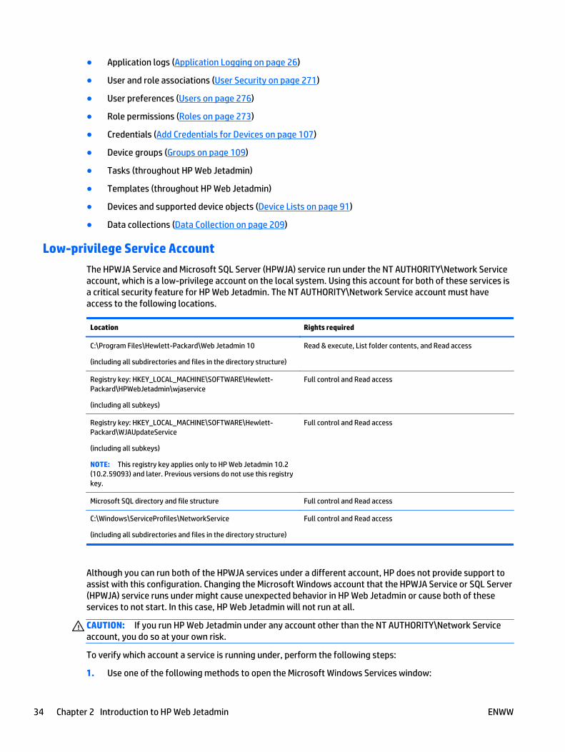
● Application logs (Application Logging on page 26)
● User and role associations (User Security on page 271)
● User preferences (Users on page 276)
● Role permissions (Roles on page 273)
● Credentials (Add Credentials for Devices on page 107)
● Device groups (Groups on page 109)
● Tasks (throughout HP Web Jetadmin)
● Templates (throughout HP Web Jetadmin)
● Devices and supported device objects (Device Lists on page 91)
● Data collections (Data Collection on page 209)
Low-privilege Service Account
The HPWJA Service and Microsoft SQL Server (HPWJA) service run under the NT AUTHORITY\Network Serviceaccount, which is a low-privilege account on the local system. Using this account for both of these services isa critical security feature for HP Web Jetadmin. The NT AUTHORITY\Network Service account must haveaccess to the following locations.
Location Rights required
C:\Program Files\Hewlett-Packard\Web Jetadmin 10
(including all subdirectories and files in the directory structure)
Read & execute, List folder contents, and Read access
Registry key: HKEY_LOCAL_MACHINE\SOFTWARE\Hewlett-Packard\HPWebJetadmin\wjaservice
(including all subkeys)
Full control and Read access
Registry key: HKEY_LOCAL_MACHINE\SOFTWARE\Hewlett-Packard\WJAUpdateService
(including all subkeys)
NOTE: This registry key applies only to HP Web Jetadmin 10.2(10.2.59093) and later. Previous versions do not use this registrykey.
Full control and Read access
Microsoft SQL directory and file structure Full control and Read access
C:\Windows\ServiceProfiles\NetworkService
(including all subdirectories and files in the directory structure)
Full control and Read access
Although you can run both of the HPWJA services under a different account, HP does not provide support toassist with this configuration. Changing the Microsoft Windows account that the HPWJA Service or SQL Server(HPWJA) service runs under might cause unexpected behavior in HP Web Jetadmin or cause both of theseservices to not start. In this case, HP Web Jetadmin will not run at all.
CAUTION: If you run HP Web Jetadmin under any account other than the NT AUTHORITY\Network Serviceaccount, you do so at your own risk.
To verify which account a service is running under, perform the following steps:
1. Use one of the following methods to open the Microsoft Windows Services window:
34 Chapter 2 Introduction to HP Web Jetadmin ENWW
● Start > Programs > Administrative Tools > Services
● Start > Run > Services.msc
2. Double-click the service.
3. On the Properties screen, click the Log On tab.
4. Verify that the NT AUTHORITY\Network Service account is listed in the This account field.
HTTP Service
HP Web Jetadmin contains a small and embedded HTTP/HTTPS service. This service exists for three reasons:
● Smart Client application delivery (initial client access).
● Help content delivery (during client session).
● Device application file hosting (devices get jar file when directed by Device Management features).
A few key points about this HTTP service include:
● The integrated HTTP service is simple and only exists for the purpose of distributing files.
● The service contains no script execution interpreters or cgi-bin capability.
● The service does not allow file navigation.
● The service does not execute read/write calls to the HP Web Jetadmin database.
● The HTTP/HTTPS server is integrated into the HP Web Jetadmin service, which runs as a low-privilegeaccount on the local host.
● The HTTP service does not run in kernel mode.
The HTTP service can be configured to run default HTTPS and uses certificates that are obtained through alocal certificate-authority. When HTTPS is enabled, it enforces authentication between the users IE browserand the local HTTP service. This provides tighter security for initial HP Web Jetadmin client launch than isprovided by HTTP. Some environments may require that all HTTP servers enforce and run default HTTPS.
Characteristics of the HTTPS service are:
● HTTPS can be enabled as part of a post-install procedure with HP Web Jetadmin security settings.
● HTTPS requires that the user obtain a certificate from a certificate authority.
● HTTPS can only be enabled through a client running on the local system hosting HP Web Jetadminsoftware.
The default port for HTTP is 8000. The default port for HTTPS is 8443. If your installation requires a differentport on the HTTP server that is embedded in HP Web Jetadmin, you can change the HttpPort andHttpsPort entries in the HP Web Jetadmin configuration file. TheHP.Imaging.Wjp.Core.WebServer.config.xml file is available in the following directory:
C:\Windows\ServiceProfiles\NetworkService\AppData\Local\Hewlett-Packard\HPWebJetadmin\WjaService\config
If you change the port entries, you must restart HP Web Jetadmin.
NOTE: To change the program link, go to Start > All Programs > HP Web Jetadmin 10. Right-clickHP Web Jetadmin, and then select Properties. Change the port number in the link variable to the new portnumber.
ENWW The HP Web Jetadmin Server 35
Localization
HP Web Jetadmin is localized in several languages. All the available languages are automaticallyimplemented when you install HP Web Jetadmin. There are no additional steps required after the installationto enable the language support.
The Windows Region and Language settings on the client used to access HP Web Jetadmin determine thelanguage in which the HP Web Jetadmin software and online Help are displayed. For more information aboutspecifying the Region and Language settings, see the Microsoft documentation for the version of Windowsthat is running on the client.
If the Region and Language settings on the client specify a language that HP Web Jetadmin does not support,the software and online Help are displayed in English.
HP Web Jetadmin might not be localized at every software release. If a software release is not localized,some of the new content in the software and online Help for that release might be displayed in English whileother content is displayed in the language specified by the Region and Language settings.
When you use the Export feature, the exported content might contain information based on the Region andLanguage settings specified on the server where HP Web Jetadmin is installed instead of the Region andLanguage settings specified on the client.
Localized versions of the HP Web Jetadmin 10.3 Installation and Setup Guide and the HP Web Jetadmin 10.3User Guide are available from the HP Support Center.
HP Web Jetadmin Network Traffic and Behavior
The HP Web Jetadmin server application performs a number of actions including:
● Client Event Notification: When users are logged into the application, a separate client application isrunning on the local desktop host. HP Web Jetadmin server uses a TCP connection to notify the clientapplication when changes exist. This notification drives the client application to connect to theserver .NET Remoting channel and order updated information. Notification happens only when:
◦ Changes in data exist for client retrieval.
◦ The server has not heard any communication from the client over a predetermined period of time.
● Supplies Alerts Polling: When devices exist in supplies groups, Supplies Alerts are enabled (Alertson page 176). The Alerts features affect both user alerts (by email or a log) and other supplies-relatedreports. All of the alerts are based on user-selected threshold values. When the supply level value for adevice is not close to the specified supply threshold, HP Web Jetadmin polls that device more slowly,taking up less network bandwidth. When the supply level value for a device is close to the specifiedsupply threshold, HP Web Jetadmin polls that device more often. This smart-polling mechanismensures that the supply level alert is delivered in a timely manner while limiting the polling that is doneon the network. Supplies Alerts polling is integrated with other kinds of polling within theHP Web Jetadmin system which means that polling is performed only when stale information isdetected.
● Slow Polling: HP Web Jetadmin uses a slow-polling mechanism that queries for device information. Thismechanism is user-configurable; faster settings put a larger load on the network (see documentationon application settings and the training module on application maintenance). This slow-pollingmechanism is used for a variety of tasks including:
◦ Users are viewing lists and one or more displayed information attributes has become stale.
◦ Automatic Device Groups exist (Groups on page 109).
● Background Tasks: Many features in HP Web Jetadmin can be launched automatically or manually by auser logged into a client application session. In either case, these can become background tasks that
36 Chapter 2 Introduction to HP Web Jetadmin ENWW

can be run without a user being logged into a client application session. Background tasks are managedcentrally by HP Web Jetadmin software and the user can display them at any time through a taskmanager interface. The Active Tasks task module is one way users can view running tasks.
The HP Web Jetadmin Client● ClickOnce Software Installation and Launch
● HP Web Jetadmin Client's Sleep State
Users gain access to HP Web Jetadmin through a local .NET client application. The application runs on anysupported client desktop. The first time a client accesses the HP Web Jetadmin server, HP Web Jetadmininstalls client files and launches a Windows client session. This client session communicates with theHP Web Jetadmin application as it runs on the server. Client application files are left in the users’ LocalSettings directory, and the application updates the files as needed. You can run the server and clientapplications on the same host or different hosts.
For more information about the hardware and software requirements for the client application, see SystemRequirements on page 1.
ClickOnce Software Installation and Launch
● Notification that Microsoft .NET Framework Is Required
The following events occur when you start the Smart Client installation and launch:
1. Client using Internet Explorer browses HTTP service (URL: http://server:8000).
● Server detects .NET on browser client (page linked to dotnetfx.exe download at Microsoft.com).
● Browser is redirected to HP Web Jetadmin.
● Browser passes application to .NET Framework (dfshim).
● .NET Framework verifies signature, reads the XML, and launches Smart Client.
2. Smart Client is launched.
● For the first run, an Application Run dialog box is displayed to client.
● 2MB files are downloaded through the HTTP service.
● UIExec.exe is launched on client host.
3. .NET remoting begins (port 4088).
● For the first run, 50 MB files downloaded.
● The HP logo page is visible.
● The client files are updated if a newer version is detected.
4. HP Web Jetadmin Client application is started.
● The client begins detecting events, executing calls, and more.
● The help content traverses the HTTP service.
● All other client communication is through .NET remoting.
ENWW The HP Web Jetadmin Client 37
Notification that Microsoft .NET Framework Is Required
The HP Web Jetadmin server can detect whether or not Microsoft .NET Framework is installed on the host. Ifthe HP Web Jetadmin server detects that .NET Framework is not installed, HP Web Jetadmin displays amessage with instructions to install .NET Framework or start HP Web Jetadmin.
Users must have admin privileges to install .NET Framework. The Start HP Web Jetadmin link launches theclient after .NET Framework is installed.
HP Web Jetadmin Client's Sleep State
When the HP Web Jetadmin client is started and then goes into a sleep or power-save state, it may fail withan Unexpected Error when the client system is brought back up to a “run” or “on” state. This is due to theHP Web Jetadmin server host losing regular contact with the client host. The server host, once it loses regularcontact, will break the connection with the client session. Once the client system is out of the sleep state andtries to contact the server, access is denied and the client stops causing an Unexpected Error. You need tothen restart the client.
Shared Configuration Options for all Views● General Shared Configuration Options
● Shared Configuration Options for Network
● Shared Configuration Options for Email
● Shared Configuration Options for Discovery
● Shared Configuration Options for Server Maintenance
● Shared Configuration Options for Credentials
The following sections describe the configuration options that are shared among all the views inHP Web Jetadmin. To access these shared configuration options, go to Tools > Options > Shared.
General Shared Configuration Options
● Configure the Database Settings
● Configure the Data Collection Option
General settings are those settings that do not fit into any other category for shared configuration options.
Configure the Database Settings
This option allows you to select the memory size for the database.
Following are steps to configure this option:
1. On the top menu bar, access Tools > Options > Shared > General > Database.
2. Select the memory size from the drop-down list.
NOTE: This feature is not available when HP Web Jetadmin is using a remote database.
3. Select database query timeout from the drop-down list.
4. Click the Apply button.
38 Chapter 2 Introduction to HP Web Jetadmin ENWW
Configure the Data Collection Option
You can allow data about your printers and implementation of HP Web Jetadmin to be collected and madeanonymous. HP Web Jetadmin uses an Internet connection to transmit this anonymous data to HP. HP usesthis anonymous data to improve products and services.
IMPORTANT: HP is committed to protecting your privacy and the integrity of your computer. You canenable and disable this feature at any time. Your name, address, email address, and other sensitive data arenot sent to HP.
To configure this option, perform the following steps:
1. Go to Tools > Options > Shared > General > Data Collection.
2. To enable the collection of anonymous data, select the Enable data collection checkbox.
-or-
To disable the collection of anonymous data, clear the Enable data collection checkbox.
Shared Configuration Options for Network
● Configure the SNMP Settings
● Configure the HTTP Settings
● Configure the HTTPS Settings
● Configure the DNS Settings
Network settings impact how HP Web Jetadmin behaves on your network and how it performs for functionslike discovery.
Configure the SNMP Settings
HP Web Jetadmin uses the SNMP protocol to gather information from the devices. You can configure theSNMP timeout value and SNMP retries. On some networks, SNMP timeouts and retries should be increasedbecause of low bandwidth or slow links. Also, decreasing SNMP timeouts and retries might improve discoveryperformance on some networks.
Your network topology might cause slow response times; if so, increase the timeout value. Or, you mightwant to set the number of retries to a higher number to protect against packet loss.
NOTE: Increasing SNMP values can increase the time required to perform a discovery.
Following are steps to configure this option:
1. On the top menu bar, access Tools > Options > Shared > Network and select SNMP.
2. Configure the desired settings:
● SNMPv1 timeout value: Specify how long HP Web Jetadmin waits for a reply from a network querythat is sent to SNMPv1 devices. The default is 500 ms.
● SNMPv3 timeout value: Specify how long HP Web Jetadmin waits for a reply from a network querythat is sent to SNMPv3 devices. The default is 1000 ms.
● SNMP retries: Specify how many times HP Web Jetadmin retries an SNMP communication withdevices after a timeout occurs. The default is 3.
3. Click the Apply button.
ENWW Shared Configuration Options for all Views 39
Configure the HTTP Settings
HTTP options enable you to specify a web proxy server and port number from which a client can access theproxy server. A security barrier is enabled on your internal network when accessing external web sites thatare required by HP Web Jetadmin.
Following are steps to configure this option:
1. On the top menu bar, access Tools > Options > Shared > Network and select HTTP.
2. Configure the desired settings:
● HTTP proxy address settings: If your environment includes a proxy server, enter the HTTP proxyaddress settings. Identify the address and the port number HP Web Jetadmin should use tocommunicate through the proxy server.
● HTTP proxy user settings: Check Use HTTP proxy credentials to use HTTP proxy credentials andthen enter the user and password.
● Download settings: Check Allow download to allow downloads.
● HTTP timeout: Specify the number of seconds that an HTTP connection can be idle before atimeout occurs. The default is 30. On networks that have a low bandwidth or slow links, you canincrease the HTTP timeout period. On some networks, decreasing the HTTP timeout period mightimprove the performance of discoveries.
NOTE: The HTTP timeout also impacts the ClickOnce Smart Client start-up.
3. Click the Apply button.
Configure the HTTPS Settings
The HP Web Jetadmin HTTP service runs without certificates. If you add a certificate, the HTTP server runs inHTTPS mode, which means that secure sockets layer (SSL) communication is enforced. For more informationabout running in HTTPS mode, see Implement SSL on page 13.
CAUTION: For new server certificates, you must install 2048-bit certificates. Any previously installed 1024-bit server certificates continue to function correctly.
Configure the DNS Settings
By default, HP Web Jetadmin enables DNS lookups. You can turn them off if desired.
Following are steps to configure this option:
1. On the top menu bar, access Tools > Options > Shared > Network and select DNS.
2. Configure the desired settings:
● Enable DNS lookups: Check this box to enable HP Web Jetadmin to perform DNS lookups.
3. Click the Apply button.
Shared Configuration Options for Email
● Configure the SMTP Settings
● Manage the Shared Email Addresses
Options in Email provide a way to configure settings to enable email communications from HP Web Jetadminand also to manage email addresses.
40 Chapter 2 Introduction to HP Web Jetadmin ENWW
Configure the SMTP Settings
SMTP options sets the SMTP gateway for relaying messages to email user accounts. These types ofmessages are used to convey alerts event details to recipients, reports and reports data export details torecipients, and device list export details to recipients.
Following are steps to configure this option:
1. On the top menu bar, access Tools > Options > Shared > Email > SMTP.
2. Configure the desired settings:
● SMTP server settings: Enter the IP address or hostname and the port number for the mail servergateway.
● SMTP user settings: Enter the user name and password; these are optional user credentials whenSMTP authentication exists.
● Default ‘from’ address: Enter the email address. This address exists in each email message sentby the application (the default is [email protected]). Enter the username and password; these areoptional user credentials when SMTP authentication exists.
3. Click the Apply button.
Manage the Shared Email Addresses
This option allows email addresses to be added and maintained for use in Reports on page 198, Alertson page 176, and Device Lists on page 91.
Following are steps to configure this option:
1. On the top menu bar, access Tools > Options > Shared > Email > Addresses.
2. Configure the desired settings:
● New: Type the new email address and select the preferred language. Then click OK.
● Remove: Select an existing email address and click Remove. When prompted, confirm the action.
● Edit: Select an existing email address and click Edit. Make changes to the email address and clickOK.
Shared Configuration Options for Discovery
● Configure Large Subnets for IP Range Discoveries
● Manage the IP Ranges for Discoveries
● Manage the Address Lists for Specified Address Discoveries
You can search for devices located within a range of IP addresses (multiple IP ranges can be designated).
Configure Large Subnets for IP Range Discoveries
You can choose to specify a large subnet range using the larger subnet address feature (Tools > Options >Shared > Discovery > Methods > IP Range > General). Large networks are considered any network biggerthan a Class B network, which has up to 65,000 nodes.
Following are steps to configure this option:
ENWW Shared Configuration Options for all Views 41

1. On the top menu bar, access Tools > Options > Shared > Discovery > Methods > IP Range > General.
2. To search for subnets larger than Class B (65,000 nodes), click Allow large subnet discoveries.
3. Click the Apply button.
To define the IP ranges, see Manage the IP Ranges for Discoveries on page 42.
Manage the IP Ranges for Discoveries
HP Web Jetadmin can search for devices located within a range of IP addresses (multiple IP ranges can bedesignated) (IP Range Discovery on page 131).
Following are steps to configure this option:
1. On the top menu bar, access Tools > Options > Shared > Discovery > Methods > IP Range > IP Ranges.
2. Choose the action to take:
● Select an IP range.
● Add: Add an IP range. Type the range in First address and Last address; then type a description (ifdesired) in Description. Click Add.
Calculate range: To calculate a range, click Calculate range. The Calculate IP Range page isdisplayed:
◦ Subnet from my computer: Automatically use IP address ranges currently found on the localsubnet of your computer. You can add a description in Description if desired.
◦ Subnet from WJA server: Automatically use IP address ranges currently found on the subnetof the HP Web Jetadmin server. You can add a description in Description if desired.
◦ Subnet from network address: Type a known IP address and subnet mask. You can add adescription in Description if desired.
● Edit: Make changes to IP ranges. Follow the steps in the bulleted item above for adding an IPrange.
● Delete: Remove addresses from the list by highlighting the address and clicking Delete.
● Import: If desired, import a range list by clicking Import; then browse for the range list.
● Export: If desired, export a range list by clicking Export; then browse for the location where youwant to store the range list.
Manage the Address Lists for Specified Address Discoveries
The Specified Address option lets you manage lists of specified addresses for discoveries. The addresses andgroups managed through this option can be selected while launching or scheduling discoveries through theDevice Discovery wizard (see Discover Devices (the Device Discovery Wizard) on page 149).
Following are steps to configure this option:
1. On the top menu bar, access Tools > Options > Shared > Discovery > Methods > Specified Address.
2. Add a new address group:
a. Click New. The Add a specified address group page is displayed.
b. Type the name of the address group.
c. To add an IP address to the group, click Add.
d. The Add specified address dialog is displayed. Type the IP address or hostname.
42 Chapter 2 Introduction to HP Web Jetadmin ENWW
e. Click Add. To continue adding IP addresses or hostnames, repeat these steps.
f. When all IP addresses or hostnames have been added, click Close.
g. Click OK two times.
3. Edit a specified address group name:
a. Highlight the group and click Edit. The Add specified address group page is displayed.
b. Change the group name.
c. Click OK two times.
4. Remove a specified address from a group:
a. Highlight the group and click Edit. The Add specified address group page is displayed.
b. Highlight the IP address or hostname and click Remove.
c. Click OK two times.
5. Delete a specified address group:
a. Highlight the group and click Delete.
b. Click OK.
Shared Configuration Options for Server Maintenance
● Configure the Schedule for Server Maintenance
● Configure the Retention Period for the Discovery History
● Configure the Retention Period for the Configuration History
● Configure the Retention Period for the Alerts History
● Manage the Report Data
Server Maintenance settings help you automatically maintain your server.
Configure the Schedule for Server Maintenance
Your server is automatically cleaned up daily, but you can specify the time of day that the cleanup shouldoccur. This is when the HP Web Jetadmin service performs routine clean-up tasks. These tasks are betterperformed when the HP Web Jetadmin service is not busy doing other processor intensive tasks such asDiscovery, Reports Data Collection, exporting Device List data, and more. Select a time that you know theHP Web Jetadmin service is not doing other processor intensive tasks.
The scheduled Server Maintenance task removes unneeded data from the HP Web Jetadmin databasetables. This is temporary data used in normal HP Web Jetadmin processes throughout the day. No user ordevice-related information is removed from the system.
Following are steps to configure this option:
1. On the top menu bar, access Tools > Options > Shared > Server Maintenance and select Schedule.
2. Enter the time you want the server cleaned up every day.
3. Click the Apply button.
Configure the Retention Period for the Discovery History
This option allows you to select the memory size for the database.
ENWW Shared Configuration Options for all Views 43

Following are steps to configure this option:
1. On the top menu bar, access Tools > Options > Shared > Server Maintenance > Discovery.
2. In the Retention time box, specify the number of days that the discovery history is retained. The defaultis 90.
3. Click the Apply button.
Configure the Retention Period for the Configuration History
This option allows you to select the number of days to retain configuration history.
Following are steps to configure this option:
1. On the top menu bar, access Tools > Options > Shared > Server Maintenance > Configuration.
2. In the Retention time box, specify the number of days that the configuration history is retained. Thedefault is 30.
3. Click the Apply button.
To clear all previous configuration history, click Clear History.
Configure the Retention Period for the Alerts History
This option allows you to select the memory size for the database.
Following are steps to configure this option:
1. On the top menu bar, access Tools > Options > Shared > Server Maintenance > Alerts.
2. In the Retention time box, specify the number of days that the entries in the alerts log are retained. Thedefault is 30.
3. Click the Apply button.
To clear the log, select Clear History.
Manage the Report Data
As data is collected for reports, it is stored in tables within the HP Web Jetadmin database. You can specifyhow long to retain data for reporting purposes and delete data that has been retained by HP Web Jetadminfor reporting purposes. Data retention is set to one year beyond the initial collection date. You can changethis value to a maximum of five years through this option.
Follow these steps:
1. On the top menu bar, access Tools > Options > Shared > Server Maintenance > Reports.
2. Select the type of data to delete:
● All data: Delete all data that has been collected to-date, as though no data collections had everbeen done.
● User data: You will be asked to identify the user and then confirm your request.
● Device data: Delete device data that has been collected to-date, as though no data collections hadever been done.
3. Click Delete Data. Confirm the delete request by clicking Yes.
44 Chapter 2 Introduction to HP Web Jetadmin ENWW
4. In the Retention time box, specify the number of years that the report data is retained. The default is 1.
5. Click the Apply button.
Shared Configuration Options for Credentials
● All About Credentials
● Clear the Credentials
● Manage the Global SNMPv1 Get Community Names
● Manage the Global SNMPv1 Set Community Names
● Manage the Global SNMPv3 Credentials
● Manage the Global EWS Passwords
● Manage the Global File System Passwords
● Manage the Domain Credentials
All About Credentials
● Credentials Store
● Credentials Delegation
● Credentials Needed
● What happened to the HP Jetdirect Device Password?
● Restricting Configuration by Device Group
HP Web Jetadmin can configure many devices simultaneously. This saves device administrators from havingto contact every device separately for the purpose of assigning configuration items like passwords and othercredentials. Many environments have password policies that make the device administrator have toreconfigure security credentials periodically. The power of HP Web Jetadmin fleet management lends itselfto configuration of many devices simultaneously.
Credentials Store
The concept of a Credentials Store is not new to HP Web Jetadmin. Older versions of HP Web Jetadmin storedcredentials onto the devices as they were used and configured. This feature keeps HP Web Jetadmin usersfrom having to provide a credential every time a device is configured that requires one.
The Credentials Store is a portion of the HP Web Jetadmin database that securely encrypts and stores devicecredentials when ever a correct credential value is authenticated at the device. These values are stored on aper credential and per device basis.
Here is a list of HP device credentials used by HP Web Jetadmin:
● EWS Password: Blocks unauthorized access to the device-embedded HTTP interface. It is alsosynchronized with the HP Jetdirect telnet password.
● File System Password: Protects the printer disk and other storage facilities from unauthorized access.
● SNMPv3 Credentials: Consists of user name, passphrase1, and passphrase2 which are all used whenSNMPv3 is enabled. This version of SNMP secures and authenticates communication betweenmanagement applications like HP Web Jetadmin and the device. This protocol is used when strongsecurity is required.
ENWW Shared Configuration Options for all Views 45
● SNMP Set Community Name: A grouping mechanism for SNMPv1/v2 used as a security mechanism bymany customers. Device configuration is not possible without knowledge of the Set name value. TheSet name value traverses the network in clear text and can be “sniffed” by eavesdroppers.
● SNMP Get Community Name: Sometimes used to prevent device discovery from other HP Web Jetadmininstallations. Devices only respond to Get packets that have the correct value. The Get name valuetraverses the network in clear text and can be “sniffed” by eavesdroppers.
Two actions cause the value of any credential to be stored:
● Configuration: The credential becomes stored once it has been configured onto the device.
● Use: The credential value, when used successfully, becomes stored.
HP Web Jetadmin reuses stored credentials any time it encounters the requirement for them. Whenconfiguring a device that has had a credential stored, you are not required to re-enter the credential intoHP Web Jetadmin. The application uses the credential in the background. In fact, you are not even required toknow the credential because HP Web Jetadmin is using stored values.
Credentials Delegation
With credentials stored in the Credentials Store, HP Web Jetadmin can apply them transparently any time theneed arises. This is known as credentials delegation. While configuring devices, you do not have to rememberor even know the credential to perform the configuration. You just need access to HP Web Jetadmin anddevice configuration features. Characteristics of credentials delegation are:
● Only one or a few device administrators know the device credentials.
● Some HP Web Jetadmin users are allowed configuration access to the devices via Roles and UserSecurity.
● Users can be added or removed from this delegation through Roles and User Security (User Securityon page 271).
● Other HP Web Jetadmin users can be restricted from device configuration.
● Knowledge about device passwords is required before you can change any password value.
Credentials delegation is used to allow configuration of devices without having to share the credential“secrets” across a large distribution. Staffs can control and configure devices while administrators controland configure passwords. Any user with access to devices and configuration features has delegated access tothe Credential Store.
Credentials Needed
When HP Web Jetadmin, during an action such as device configuration, encounters a device with a credentialsuch as SNMP Set Community Name, it follows a specific sequence. Here is a simplified example showing howHP Web Jetadmin attempts to resolve a credential:
● HP Web Jetadmin checks the Credential Store for a credential.
● If a credential exists, HP Web Jetadmin attempts the configuration using the credential value.
If a credential does not exist, HP Web Jetadmin checks Global Credentials.
● If the configuration is successful, the credential check is resolved and complete.
If it fails, HP Web Jetadmin checks Global Credentials.
During a user-attended configuration session, HP Web Jetadmin prompts for credentials. If the user does notsupply the credential or the session is not live, the device is flagged as Credentials Required and listed in the
46 Chapter 2 Introduction to HP Web Jetadmin ENWW
Credentials Required column that can be enabled in any device list (Columns for Device Lists on page 93).You can right-click the device and add the needed credential to the system in order to resolve this state.
What happened to the HP Jetdirect Device Password?
HP Web Jetadmin enables device security by providing management over appropriate, device-based securitysettings. The HP Jetdirect password that was used by HP Web Jetadmin in the past is a software securitysolution and not a device-based security solution. That is, the password itself had to be recognized andauthenticated by earlier revisions of HP Web Jetadmin software. Other applications did not recognize thispassword and did not force users to prove knowledge of the password.
As security features have become more sophisticated and device based security has improved,HP Web Jetadmin developers have opted out of using the HP Jetdirect device password as a protectivemechanism for device authentication. Instead, HP recommends that you choose one of the following tworecommendations providing device security:
● SNMP Set Community Name: Devices will not allow an SNMP Set from any application without the SetCommunity Name correctly embedded in the SNMP packet. If the Set name in the packet is “public” andthe Set name on the device is “George”, the device will not accept or acknowledge the packet. SetCommunity Names traverse the network in clear text and, therefore, can be “sniffed” or viewed byeavesdroppers. In most environments, security provided a Set Community Name may provide adequatesecurity.
● SNMPv3: Devices configured via SNMPv3 offer significant security benefits. First, SNMPv3 configures auser account and two pass-phrases onto the device that the user (or application) must authenticate.This blocks unauthorized management of devices, and the account/pass-phrase details do not traversethe network in clear text which makes it difficult for eavesdroppers to learn the “secrets”. Second, thecommunication between the management application and the device is encrypted using the SNMPcredentials so information about the device is protected. SNMPv3 is recommended in security-sensitiveenvironments.
Restricting Configuration by Device Group
Within the model of device credential delegation, restriction to specific device configuration can be furtherdefined in User Security using the Restriction type Groups (Restrict Roles to Device Groups on page 274).
Consider the following layers of security:
● Access to device credential values: Credential Store/selected device administrators (Credentials Storeon page 45).
● Access to HP Web Jetadmin: Users and Roles (User Security on page 271).
● Access to device credentials store: Roles/Feature Permissions (Roles on page 273).
● Access to specific devices: Roles/Device Group Membership/Device Feature Permissions (Roleson page 273).
Each layer uses HP Web Jetadmin security to protect against unauthorized access:
1. First, device passwords are protected by one administrator or a few select administrators.
2. Second, Users and Roles allow only authorized users to log onto HP Web Jetadmin.
3. Third, Roles and Feature Permissions allow only authorized users access to configuration access to alldevices.
4. Finally, Roles, Device Group Membership, and Device Feature Permissions allow authorized users tospecific devices based on device group membership and specified device configuration features.
ENWW Shared Configuration Options for all Views 47

All devices and configuration options outside of the Group Restriction Type are secured from unauthorizedaccess.
Clear the Credentials
Global credentials are credentials that HP Web Jetadmin uses for any device; they are an easy way for you toenter common credentials up front. Global credentials can be set for SNMPv1 Get Community Name, SNMPv1Set Community Name, SNMPv3 Credentials, and EWS Password. If these credentials have been set, anddevice operations (for example, device configuration) require credentials, then the global credential will betried. If the operation succeeds for the devices with the global credential, that global credential will be storedwith the device. It still remains a global credential for other devices, but now that specific device has aworking credential stored with it.
For example: User “A” enters global credentials for SNMPv1 Get Community Name as “mine” and “yours”.User “B” tries to interact with device “X”, which has a community name already set. HP Web Jetadmin firsttries global credentials “yours” and “mine”; “yours” works. “Yours” is the stored as a regular credential fordevice “X”. The next time any user tries to interact with device “X”, HP Web Jetadmin will use the regularcredential for that device (which is now “yours”) and will ignore any global credentials. However, if theregular credential “yours” becomes out of date, this process starts over again.
Following are steps to configure this option:
1. On the top menu bar, access Tools > Options > Shared > Credentials > General.
2. Configure the desired settings:
● Clear global credentials: Clears every temporary, global, device-specific credential.
● Clear all stored credentials: Clears every temporary, global, device-specific credential.
3. You must then confirm or cancel your request.
Manage the Global SNMPv1 Get Community Names
The SNMP Get Community Name object is configurable from within security settings. It can actually cause adevice to disappear. For example:
User A is running an instance of HP Web Jetadmin known as Web Jetadmin A. This user is managing a set ofdevices that are also being managed by User B. User B is running another copy of HP Web Jetadmin known asWeb Jetadmin B. This B copy of HP Web Jetadmin is being used at the help desk.
User B tries to provide a measure of security by changing the default Get Community Name on the set ofdevices from public to private using HP Web Jetadmin. User A opens HP Web Jetadmin and notices thatall the devices have become non-responsive and show only a device communication error. QuickDevice Discovery does not help. Upon checking the printer itself, User A finds it to be powered on. User A canalso reach the printer web server interface through a browser.
CAUTION: Changing the Get Community Name can cause devices to become unresponsive to managementapplications such as HP Web Jetadmin. The SNMP protocol will no longer respond to public queries andother management applications on the network will not be able to communicate with these devices.
Following are steps to configure this option:
1. On the top menu bar, access Tools > Options > Shared > Credentials > Device > SNMPv1 GetCommunity Name.
2. To add a community name, click Add and type the community name. Enter an associated (or easier)name in Remember credential as and click OK.
3. To remove a Get Community Name, click Remove.
48 Chapter 2 Introduction to HP Web Jetadmin ENWW
Manage the Global SNMPv1 Set Community Names
The SNMP Set Community Name is a grouping mechanism for SNMPv1/v2 that has been adopted as a securitymechanism by many customers. Device configuration is not possible without knowledge of the Set namevalue. The Set name value traverses the network in clear text and can be easily detected by eavesdroppers.
Following are steps to configure this option:
1. On the top menu bar, access Tools > Options > Shared > Credentials > Device > SNMPv1 SetCommunity Name.
2. To add a community name, click Add and type the community name. Enter an associated (or easier)name in Remember credential as and click OK.
3. To remove a Set Community Name, click Remove.
Manage the Global SNMPv3 Credentials
SNMPv3 secures and authenticates communication between management applications, such asHP Web Jetadmin, and devices. SNMPv3 is used when strong security is a requirement.
SNMPv3 credentials consist of a user name, authentication protocol, private protocol, passphrase1, andpassphrase2. HP Web Jetadmin uses these credentials when SNMPv3 is enabled.
HP Web Jetadmin can discover devices that have SNMPv3 fully enabled. However, you must configureHP Web Jetadmin to discover SNMPv3-enabled devices. For more information, see Configure the GeneralSettings for Device Discoveries on page 56.
To discover SNMPv3-enabled devices, HP Web Jetadmin requires the SNMPv3 credentials for the devices.HP Web Jetadmin detects SNMPv3 credentials for devices in the following ways:
● SNMPv3 is enabled in HP Web Jetadmin and SNMPv3 credentials are configured on the devices. In thiscase, HP Web Jetadmin stores the credentials in its credentials store, and then uses these credentialswhen communicating with the devices.
● SNMPv3 credentials are added to the HP Web Jetadmin global credentials store and these globalcredentials match the credentials on the devices. In this case, when HP Web Jetadmin communicateswith an SNMPv3-enabled device, it tries the values in the global credentials store. If the globalcredential values are valid and HP Web Jetadmin can communicate with the device, the credentialvalues are stored on each device.
Devices that HP Web Jetadmin discovers through SNMPv1 and have SNMPv3 enabled through some othermethod, such as the HP Embedded Web Server or another instance of HP Web Jetadmin, have a DeviceCommunication Error status when HP Web Jetadmin attempts to re-establish communication. To reset thesedevices to SNMPv3-enabled, use the Refresh Selection command in the device list.
To manage the global SNMPv3 credentials, perform the following steps:
NOTE: SNMPv3 does not support the No Authentication Protocol and No Privacy Protocol modes.
1. Go to Tools > Options > Shared > Credentials > Device > SNMPv3.
2. To add an SNMPv3 credential, perform the following steps:
a. Click the Add button.
b. In the User name box, enter the user name.
c. From the Authentication Protocol list, select MD5 or SHA1.
d. In the Authenticated password and Confirm authenticated password boxes, enter theauthenticated password (minimum of 8 characters).
ENWW Shared Configuration Options for all Views 49
e. From the Privacy Protocol list, select the DES or AES-128 option.
f. In the Private password and Confirm private password boxes, enter the private password(minimum of 8 characters).
g. In the Remember credential as box, enter a name for this credential that is easy to remember.
h. Click the OK button.
3. To delete an SNMPv3 credential, select the credential from the list, and then click the Remove button.
Manage the Global EWS Passwords
The EWS password blocks unauthorized access to the device-embedded HTTP interface. Also, it issynchronized with the HP Jetdirect telnet password.
Following are steps to configure this option:
1. On the top menu bar, access Tools > Options > Shared > Credentials > Device > EWS.
2. To add an EWS password, click Add and type the username and password. Then enter an associated (oreasier) name in Remember credential as and click OK.
3. To remove an EWS password, click Remove.
Manage the Global File System Passwords
The File system password protects the printer disk and other storage facilities from unauthorized access.
Following are steps to configure this option:
1. On the top menu bar, access Tools > Options > Shared > Credentials > Device > File System.
2. To add a file system password, click Add and type the password. Then enter an associated (or easier)name in Remember password as and click OK.
3. To remove a file system password, click Remove.
Manage the Domain Credentials
This option allows you to enter domain credentials when needed.
Following are steps to configure this option:
1. On the top menu bar, access Tools > Options > Shared > Credentials > Domain Browsing.
2. Configure the desired settings:
● Add Domain: Add a domain. The Add Domain dialog is displayed. Type the domain or browse for it.If you browse, you might be prompted for credentials.
● Set Credential: Enter the username and password. In the Stored column, set credentials for anydomain with Yes.
● Remove: Delete a domain; select a domain listed and click Remove.
● Test: Test the domain. Credentials might be required.
Application Management Configuration Options● Configure the Settings for the Application Log
● Restore the Default Roles
50 Chapter 2 Introduction to HP Web Jetadmin ENWW

The following sections describe the configuration options for functional areas in the ApplicationManagement view. To access these configuration options, go to Tools > Options > ApplicationManagement.
Configure the Settings for the Application Log
This option lets you set the time for application log data to be saved. For more information about theApplication Log, see Application Logging on page 26.
Following are steps to configure this option:
1. On the top menu bar, access Tools > Options > Application Management > Application Log.
2. Configure the desired settings:
● Save log entries for: Select the number of days that the log entries are saved. The default is 60.
● Maximum number of entries: Specify the maximum number of entries that are included in the log.Any entries over this number are placed in the archive file. The default is 20,000.
● Clear Log: Clear the Application Log. You must then confirm or cancel your request.
3. If log file entries are older than the limit specified in Save log entries for, they can be archived to a file.Select the check box for Archive expired entries to file. (The location of the file is displayed.)
The file will be written to the HP Web Jetadmin server disk in the location displayed. This location ischosen by the operating system and is typically a hidden or system folder.
NOTE: The Network Service user folder is typically set to be a hidden system folder in MicrosoftOperating systems. Use Tools > Folder Options to make this folder accessible through Microsoft,Windows Explorer. For specific information about these settings, see the Microsoft Windowsinstructions.
4. To clear the archive file, click Clear Archive.
NOTE: The archive file will grow indefinitely; you must manage the size of this file.
5. Click the Apply button.
Restore the Default Roles
You can use this option to restore the default user roles. For more information, see Roles on page 273.
To restore the default roles, perform the following steps:
1. Go to Tools > Options > Application Management > User Security.
2. Click the Restore button.
Device Management Configuration Options● Device Polling Configuration Options
● Devices Configuration Options
● Device Discovery Configuration Options
● Device Filters Configuration Options
● Device Tabs Configuration Options
● Configuration Options for Fleet Configurations
ENWW Device Management Configuration Options 51
● Alerts Configuration Options
● Firmware Configuration Options
● Reports Configuration Options
● Supplies Configuration Options
The following sections describe the configuration options for functional areas in the Device Managementview. To access these configuration options, go to Tools > Options > Device Management.
Device Polling Configuration Options
● Configure the Background Polling Options
● Configure the Polling Options for Device Lists
● Configure the Polling Options for Device Tabs
● Configure the Polling Options for Device Alerts and Supplies Alerts
● Configure the Polling Options for Supplies
There are several configuration options that can be set to affect how device polling is performed inHP Web Jetadmin.
Configure the Background Polling Options
Whenever you access a device list in HP Web Jetadmin, the devices on the network are polled. You candetermine how many devices and how often devices are polled by setting the rate on the Background pollingpage. You can reduce network traffic by setting a polling rate appropriate for your own environment.
HP Web Jetadmin performs a slow-poll when users access device lists. Slow polling means thatHP Web Jetadmin queries only a certain number of devices every X seconds and only for specified columns.The columns polled are based on the union of all columns in the layouts currently displayed on Device Listpages on all currently connected clients. This polling rate can be changed through Tools > Options > DeviceManagement > Device Polling > Device List. List performance can be improved by changing the polling rate;network traffic will increase.
NOTE: Another way to refresh the list more quickly is to highlight any or all devices where fast data isdesired. Selected devices in the currently visible portion of the device list are always polled at a faster ratethan non-selected devices.
Polling always occurs across all devices at the specified rate regardless of whether or not anyone is accessinga device list. Accessing a device list only affects the columns which are polled for when the polling doesoccur. Selecting devices within the visible portion of the list causes those devices to be polled for at a higherrate.
Polling is also affected by thresholds that specify how long the value for a specific column is consideredvalid. These thresholds are predefined in HP Web Jetadmin. You cannot change the predefined thresholds.Before HP Web Jetadmin polls a device for column values, it performs the following steps:
1. If HP Web Jetadmin does not have a value for a column, it polls the device. If HP Web Jetadmin canobtain a value from the device, it displays the value in the device lists.
2. If HP Web Jetadmin cannot obtain a value from the device, it checks the age of the value it has. If theage of the value is within the predefined threshold for the column, HP Web Jetadmin considers the valuevalid.
3. If the age of the value exceeds the predefined threshold for the column, HP Web Jetadmin polls thedevice to obtain the current value. If HP Web Jetadmin can obtain a value from the device, it displays the
52 Chapter 2 Introduction to HP Web Jetadmin ENWW
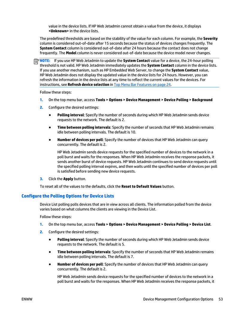
value in the device lists. If HP Web Jetadmin cannot obtain a value from the device, it displays<Unknown> in the device lists.
The predefined thresholds are based on the stability of the value for each column. For example, the Severitycolumn is considered out-of-date after 15 seconds because the status of devices changes frequently. TheSystem Contact column is considered out-of-date after 24 hours because the contact does not changefrequently. The Model column is never considered out-of-date because the device model never changes.
NOTE: If you use HP Web Jetadmin to update the System Contact value for a device, the 24-hour pollingthreshold is not valid. HP Web Jetadmin immediately updates the System Contact column in the device lists.If you use another mechanism, such as HP Embedded Web Server, to change the System Contact value,HP Web Jetadmin does not display the updated value in the device lists for 24 hours. However, you canrefresh the information in the device lists at any time to reflect the current values for the devices. Forinstructions, see Refresh device selection in Top Menu Bar Features on page 24.
Follow these steps:
1. On the top menu bar, access Tools > Options > Device Management > Device Polling > Background
2. Configure the desired settings:
● Polling interval: Specify the number of seconds during which HP Web Jetadmin sends devicerequests to the network. The default is 2.
● Time between polling intervals: Specify the number of seconds that HP Web Jetadmin remainsidle between polling intervals. The default is 10.
● Number of devices per poll: Specify the number of devices that HP Web Jetadmin can queryconcurrently. The default is 2.
HP Web Jetadmin sends device requests for the specified number of devices to the network in apoll burst and waits for the responses. When HP Web Jetadmin receives the response packets, itsends another burst of device requests. HP Web Jetadmin continues to send device requests untilthe specified polling interval expires, and then waits until the specified number of devices per pollis satisfied before sending new device requests.
3. Click the Apply button.
To reset all of the values to the defaults, click the Reset to Default Values button.
Configure the Polling Options for Device Lists
Device List polling polls devices that are in view across all clients. The information polled from the devicevaries based on what columns the clients are viewing in the Device List.
Follow these steps:
1. On the top menu bar, access Tools > Options > Device Management > Device Polling > Device List.
2. Configure the desired settings:
● Polling interval: Specify the number of seconds during which HP Web Jetadmin sends devicerequests to the network. The default is 5.
● Time between polling intervals: Specify the number of seconds that HP Web Jetadmin remainsidle between polling intervals. The default is 7.
● Number of devices per poll: Specify the number of devices that HP Web Jetadmin can queryconcurrently. The default is 2.
HP Web Jetadmin sends device requests for the specified number of devices to the network in apoll burst and waits for the responses. When HP Web Jetadmin receives the response packets, it
ENWW Device Management Configuration Options 53

sends another burst of device requests. HP Web Jetadmin continues to send device requests untilthe specified polling interval expires, and then waits until the specified number of devices per pollis satisfied before sending new device requests.
3. Click the Apply button.
To reset all of the values to the defaults, click the Reset to Default Values button.
Configure the Polling Options for Device Tabs
Device Tab polling polls device information needed to drive the device-related information on the selecteddevice tabs across all clients.
Follow these steps:
1. On the top menu bar, access Tools > Options > Device Management > Device Polling > Device Tabs.
2. Configure the desired settings:
● Polling interval: Specify the number of seconds during which HP Web Jetadmin sends devicerequests to the network. The default is 5.
● Time between polling intervals: Specify the number of seconds that HP Web Jetadmin remainsidle between polling intervals. The default is 2.
● Number of devices per poll: Specify the number of devices that HP Web Jetadmin can queryconcurrently. The default is 3.
HP Web Jetadmin sends device requests for the specified number of devices to the network in apoll burst and waits for the responses. When HP Web Jetadmin receives the response packets, itsends another burst of device requests. HP Web Jetadmin continues to send device requests untilthe specified polling interval expires, and then waits until the specified number of devices per pollis satisfied before sending new device requests.
3. Click the Apply button.
To reset all of the values to the defaults, click the Reset to Default Values button.
Configure the Polling Options for Device Alerts and Supplies Alerts
You can define how often devices should be checked to see if they warrant alerts. Frequent polling canincrease network traffic; infrequent polling might cause some device alerts to go unnoticed and, therefore,unattended. You can also specify how long an alert event stays in the alert history log, or you can clear thealerts log at any time.
You can configure static polling rates for supplies alerts subscriptions. This feature helps prevent missingalerts by keeping supplies alerts subscriptions in a static polling interval. If you enable this feature, suppliesalerts subscriptions that exceed the specified threshold are placed in static polling. These supplies alertssubscriptions remain in static polling until you disable static polling or replenish the supplies. Supplies alertssubscriptions move to the static poller on the next polling cycle of the poller the subscription is in. If youdisable this feature, qualifying supplies alerts subscriptions move from the static poller to the mostappropriate poller, which is determined by the rate of use for the supply, on the next polling cycle of thepoller the subscription is in.
Follow these steps:
1. On the top menu bar, access Tools > Options > Device Management > Device Polling > Alerts.
2. To configure polling for devices, specify the following settings:
54 Chapter 2 Introduction to HP Web Jetadmin ENWW
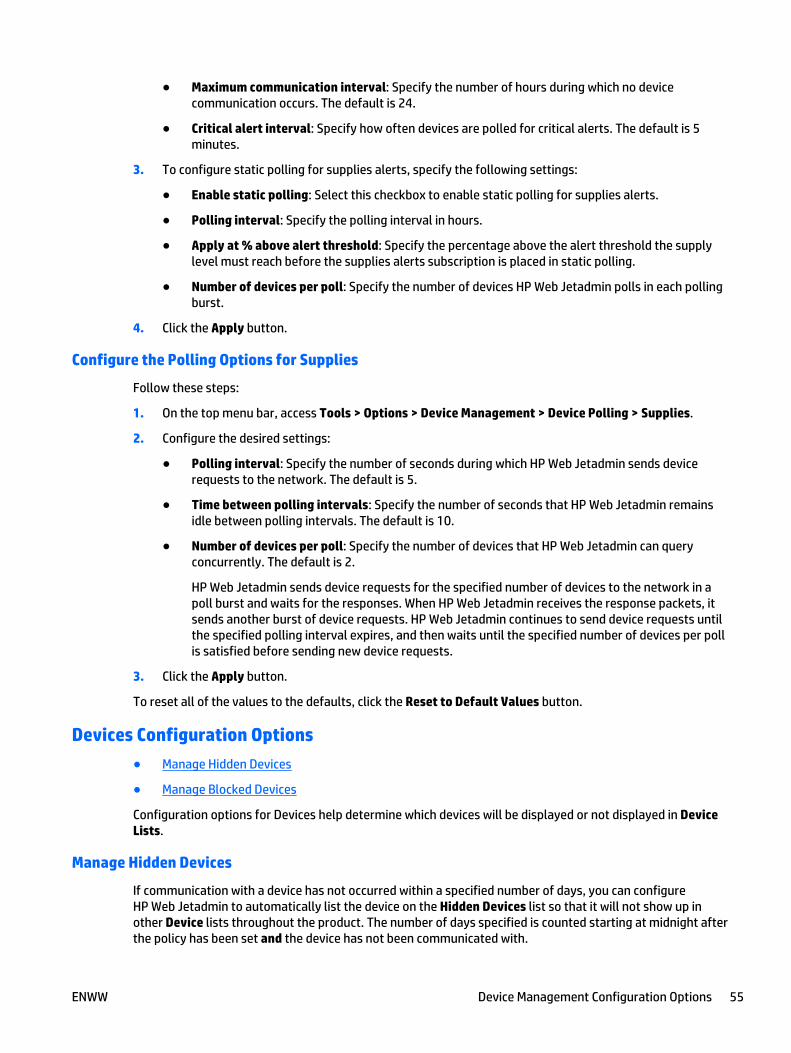
● Maximum communication interval: Specify the number of hours during which no devicecommunication occurs. The default is 24.
● Critical alert interval: Specify how often devices are polled for critical alerts. The default is 5minutes.
3. To configure static polling for supplies alerts, specify the following settings:
● Enable static polling: Select this checkbox to enable static polling for supplies alerts.
● Polling interval: Specify the polling interval in hours.
● Apply at % above alert threshold: Specify the percentage above the alert threshold the supplylevel must reach before the supplies alerts subscription is placed in static polling.
● Number of devices per poll: Specify the number of devices HP Web Jetadmin polls in each pollingburst.
4. Click the Apply button.
Configure the Polling Options for Supplies
Follow these steps:
1. On the top menu bar, access Tools > Options > Device Management > Device Polling > Supplies.
2. Configure the desired settings:
● Polling interval: Specify the number of seconds during which HP Web Jetadmin sends devicerequests to the network. The default is 5.
● Time between polling intervals: Specify the number of seconds that HP Web Jetadmin remainsidle between polling intervals. The default is 10.
● Number of devices per poll: Specify the number of devices that HP Web Jetadmin can queryconcurrently. The default is 2.
HP Web Jetadmin sends device requests for the specified number of devices to the network in apoll burst and waits for the responses. When HP Web Jetadmin receives the response packets, itsends another burst of device requests. HP Web Jetadmin continues to send device requests untilthe specified polling interval expires, and then waits until the specified number of devices per pollis satisfied before sending new device requests.
3. Click the Apply button.
To reset all of the values to the defaults, click the Reset to Default Values button.
Devices Configuration Options
● Manage Hidden Devices
● Manage Blocked Devices
Configuration options for Devices help determine which devices will be displayed or not displayed in DeviceLists.
Manage Hidden Devices
If communication with a device has not occurred within a specified number of days, you can configureHP Web Jetadmin to automatically list the device on the Hidden Devices list so that it will not show up inother Device lists throughout the product. The number of days specified is counted starting at midnight afterthe policy has been set and the device has not been communicated with.
ENWW Device Management Configuration Options 55
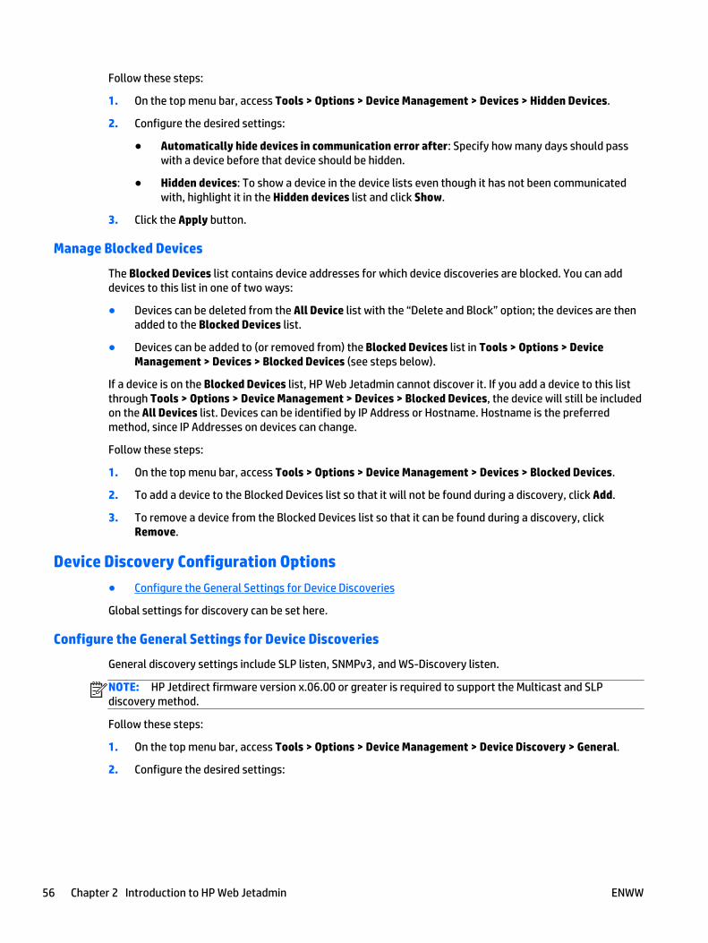
Follow these steps:
1. On the top menu bar, access Tools > Options > Device Management > Devices > Hidden Devices.
2. Configure the desired settings:
● Automatically hide devices in communication error after: Specify how many days should passwith a device before that device should be hidden.
● Hidden devices: To show a device in the device lists even though it has not been communicatedwith, highlight it in the Hidden devices list and click Show.
3. Click the Apply button.
Manage Blocked Devices
The Blocked Devices list contains device addresses for which device discoveries are blocked. You can adddevices to this list in one of two ways:
● Devices can be deleted from the All Device list with the “Delete and Block” option; the devices are thenadded to the Blocked Devices list.
● Devices can be added to (or removed from) the Blocked Devices list in Tools > Options > DeviceManagement > Devices > Blocked Devices (see steps below).
If a device is on the Blocked Devices list, HP Web Jetadmin cannot discover it. If you add a device to this listthrough Tools > Options > Device Management > Devices > Blocked Devices, the device will still be includedon the All Devices list. Devices can be identified by IP Address or Hostname. Hostname is the preferredmethod, since IP Addresses on devices can change.
Follow these steps:
1. On the top menu bar, access Tools > Options > Device Management > Devices > Blocked Devices.
2. To add a device to the Blocked Devices list so that it will not be found during a discovery, click Add.
3. To remove a device from the Blocked Devices list so that it can be found during a discovery, clickRemove.
Device Discovery Configuration Options
● Configure the General Settings for Device Discoveries
Global settings for discovery can be set here.
Configure the General Settings for Device Discoveries
General discovery settings include SLP listen, SNMPv3, and WS-Discovery listen.
NOTE: HP Jetdirect firmware version x.06.00 or greater is required to support the Multicast and SLPdiscovery method.
Follow these steps:
1. On the top menu bar, access Tools > Options > Device Management > Device Discovery > General.
2. Configure the desired settings:
56 Chapter 2 Introduction to HP Web Jetadmin ENWW

● SLP listen: Select this option to use passive discovery on port 427 for SLP signals propagated atHP Jetdirect power-on. The default for this field is off or unselected.
● SNMPv3: Select this option to enable SNMPv3 credential entry fields in HP Web Jetadmin discoverysettings. When these credentials are added for discovery settings or global credentials,HP Web Jetadmin attempts SNMPv3 queries on devices. The default for this field is off orunselected.
NOTE: SNMPv3 discoveries can be slow if not properly set. These should be targeted only atparts of the network that are known to have SNMPv3-enabled devices. Also, SNMPv3 devicesrequire that SNMPv3 credentials are entered.
● WS-Discovery listen: Select this option to use passive discovery on port 3702 for WS-Discoverysignals propagated at HP Jetdirect power-on. The default for this field is off or unselected.
3. Click the Apply button.
Device Filters Configuration Options
● Configure the Number of Days that Devices are Considered New
Configuration options for Device Filters help determine which devices will be displayed or not displayed inDevice Lists.
Configure the Number of Days that Devices are Considered New
You can specify how long a device is considered new in HP Web Jetadmin. “New” devices are displayed on theNew (Time Period) device list.
Follow these steps:
1. On the top menu bar, access Tools > Options > Device Management > Device Filters > New DevicesFilter.
2. Configure the desired settings:
● Time period for device to remain “New”: Specify the number of days that HP Web Jetadminconsiders devices new. The default is 14.
3. Click the Apply button.
Device Tabs Configuration Options
● Configure the General Options for Device Tabs
Configuration options for Device Tabs help determine how many devices will be displayed at one time inmultiple device view.
Configure the General Options for Device Tabs
For multiple device view, this configuration option determines the maximum number of devices per page forwhich status should be shown.
Follow these steps:
1. On the top menu bar, access Tools > Options > Device Management > Device Tabs > General.
2. In the Devices to allow in multi-view box, specify the maximum number of devices that are displayedin the tabs when multiple devices are selected in a device list. The default is 10.
3. Click the Apply button.
ENWW Device Management Configuration Options 57
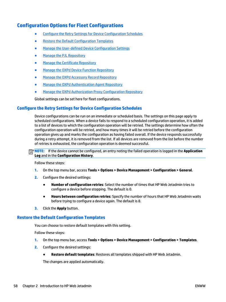
Configuration Options for Fleet Configurations
● Configure the Retry Settings for Device Configuration Schedules
● Restore the Default Configuration Templates
● Manage the User-defined Device Configuration Settings
● Manage the PJL Repository
● Manage the Certificate Repository
● Manage the OXPd Device Function Repository
● Manage the OXPd Accessory Record Repository
● Manage the OXPd Authentication Agent Repository
● Manage the OXPd Authorization Proxy Configuration Repository
Global settings can be set here for fleet configurations.
Configure the Retry Settings for Device Configuration Schedules
Device configurations can be run on an immediate or scheduled basis. The settings on this page apply toscheduled configurations. When a device fails to respond to a scheduled configuration operation, it is addedto a list of devices to which the configuration operation will be retried. The settings determine how often theconfiguration operation will be retried, and how many times it will be retried before the configurationoperation gives up and marks the configuration as having failed overall. If the device responds successfullyduring a retry attempt, it is removed from the list. If all devices are removed from the list before the numberof retries is exhausted, the configuration operation is deemed successful.
NOTE: If the device cannot be configured, an entry noting the failed operation is logged in the ApplicationLog and in the Configuration History.
Follow these steps:
1. On the top menu bar, access Tools > Options > Device Management > Configuration > General.
2. Configure the desired settings:
● Number of configuration retries: Select the number of times that HP Web Jetadmin tries toconfigure a device before stopping. The default is 0.
● Hours between configuration retries: Specify the number of hours that HP Web Jetadmin waitsbefore trying to configure a device again. The default is 8.
3. Click the Apply button.
Restore the Default Configuration Templates
You can choose to restore default templates with this setting.
Follow these steps:
1. On the top menu bar, access Tools > Options > Device Management > Configuration > Templates.
2. Configure the desired settings:
● Restore default templates: Restores all templates shipped with HP Web Jetadmin.
The changes are applied automatically.
58 Chapter 2 Introduction to HP Web Jetadmin ENWW
Manage the User-defined Device Configuration Settings
You can create custom device configuration settings, and then configure these user-defined settings ondevices. User-defined settings can provide additional information about a device that is not available byusing the device's existing configuration options. The following are examples of user-defined settings:
● Warranty expiration dates
● Lease start and stop dates
● Service maintenance dates
● Location of the device
After you create user-defined settings, the settings are available in the Config tab, device configurationwizards, device list columns, and reports.
You can export user-defined settings from one HP Web Jetadmin installation to an XML file. Then you canimport the XML file into a different HP Web Jetadmin installation.
CAUTION: Actions performed on the User Defined page are effective immediately and cannot be canceled.
NOTE: Any changes that you make to the user-defined settings might not take effect for all of theHP Web Jetadmin features until you restart HP Web Jetadmin.
Create user-defined settings
1. Go to Tools > Options > Device Management > Configuration > User Defined.
2. Click the New button.
3. On the Create User Defined Setting window, enter a name for the user-defined setting in the Settingname box.
4. To disable the user-defined setting when configuring multiple devices, select the Hide whenconfiguring multiple devices checkbox.
NOTE: Select this checkbox if the value of the user-defined setting must be unique for each device,such as an identification number. You cannot use this user-defined setting to configure multiple devicesor in templates.
-or-
To allow the user-defined setting to be used when configuring multiple devices, clear the Hide whenconfiguring multiple devices checkbox.
5. Click the OK button.
Edit user-defined settings
Changing the name of a user-defined setting does not affect any current or historical data that has beensaved for that setting. The new name should still reflect the purpose of the setting.
1. Go to Tools > Options > Device Management > Configuration > User Defined.
2. Select the user-defined setting from the list, and then click the Edit button.
3. On the Edit User Defined Setting window, enter a new name for the user-defined setting in the Settingname box.
ENWW Device Management Configuration Options 59
4. To disable the user-defined setting when configuring multiple devices, select the Hide whenconfiguring multiple devices checkbox.
NOTE: Select this checkbox if the value of the user-defined setting must be unique for each device,such as an identification number. You cannot use this user-defined setting to configure multiple devicesor in templates.
-or-
To allow the user-defined setting to be used when configuring multiple devices, clear the Hide whenconfiguring multiple devices checkbox.
5. Click the OK button.
6. On the message window, click the OK button.
Delete user-defined settings
After you delete a user-defined setting, all of the current and historical data that has been saved for thesetting is lost and the setting is removed from any templates or scheduled tasks.
1. Go to Tools > Options > Device Management > Configuration > User Defined.
2. Select the user-defined settings from the list, and then click the Delete button.
3. On the Delete User Defined Setting window, verify that the correct user-defined settings are listed, andthen click the OK button.
4. On the message window, click the OK button.
Import user-defined settings
1. Go to Tools > Options > Device Management > Configuration > User Defined.
2. Click the Import button. The Import User-Defined Settings wizard starts.
3. On the Select file page, click the Browse button.
4. On the Open window, browse to and select the file, and then click the Open button.
5. To replace duplicate user-defined settings with the settings in the XML file, select the Overwriteduplicate user-defined settings checkbox.
NOTE: If a user-defined setting that already exists in HP Web Jetadmin is overwritten by a user-defined setting in the XML file that has the same name, note the following issues:
● The templates and user-defined data for the devices lose the values for the overwritten user-defined settings.
● You must restart the HP Web Jetadmin service to display the overwritten user-defined settingscorrectly.
● You must reselect the columns for the overwritten user-defined settings in HP Web Jetadmin.
-or-
To prevent duplicate user-defined settings from being imported into HP Web Jetadmin, clear theOverwrite duplicate user-defined settings checkbox.
6. Click the Next button.
7. On the Confirm page, verify that the correct XML file is selected, and then click the Import button.
8. On the Results page, click the Done button.
60 Chapter 2 Introduction to HP Web Jetadmin ENWW
Export user-defined settings
1. Go to Tools > Options > Device Management > Configuration > User Defined.
2. Select the user-defined settings from the list.
-or-
Select the Select all checkbox.
3. Click the Export button. The Export User-Defined Settings wizard starts.
4. On the Confirm page, verify that the correct user-defined settings are listed, and then click the Exportbutton.
5. On the Save As window, browse to and select the directory where you want to save the XML file.
6. In the File name box, enter a name for the XML file, and then click the Save button.
7. On the Results page, click the Done button.
Manage the PJL Repository
You can send a file or test file with PJL configuration options to one or more printers. You can choose to havethe file sent immediately or you can schedule it.
Follow these steps:
1. On the top menu bar, access Tools > Options > Device Management > Configuration > PJL Repository.The PJL File Repository page is displayed showing current file names and descriptions.
2. To add a file to the repository, click Add File. The Add File dialog is displayed.
a. Type a unique file name or browse to the file.
b. Type a description and then click OK.
3. To delete a file:
a. Select the files from the list, and then click the Remove button.
b. On the Remove Files window, click the OK button.
Manage the Certificate Repository
Printers might need certificates to access some external web sites. You can store certificates in the certificaterepository, and then install those certificates on one or more printers. You can view detailed information fora certificate, delete certificates, and include certificates in device configuration templates.
Follow these steps:
1. On the top menu bar, access Tools > Options > Device Management > Configuration > CertificateRepository. The Certificate Repository page is displayed showing the certificates stored in therepository.
2. To import a certificate, click Import. The Open dialog is displayed. Browse to the certificate file, andthen click Open.
3. To delete a certificate, select the certificate, and then click Delete. A confirmation message is displayed.Click OK.
4. To view a certificate, select the certificate, and then click View Details.
ENWW Device Management Configuration Options 61
Manage the OXPd Device Function Repository
A device function file defines the name and functionality of a button that can be displayed on a printercontrol panel. You can import device function files into the device function repository, and then use thedevice function files to configure one or more printers. You can edit device function files, delete devicefunction files, and include device function files in device configuration templates.
Follow these steps:
1. On the top menu bar, access Tools > Options > Device Management > Configuration > OXPd DeviceFunctions. The OXPd Device Function Repository page is displayed showing the device function filesstored in the repository.
2. To import a device function file, click Import. The Open dialog is displayed. Browse to the devicefunction file, and then click Open.
3. To delete a device function file, select the file, and then click Delete. A confirmation message isdisplayed. Click OK.
4. To edit a device function file, select the file, and then click Edit. Change the settings, and then click OK.
Manage the OXPd Accessory Record Repository
An accessory record file defines how third-party applications access device accessories. You can importaccessory record files into the accessory record repository, and then use the accessory record files toconfigure one or more printers. You can edit accessory record files, delete accessory record files, and includeaccessory record files in device configuration templates.
Follow these steps:
1. On the top menu bar, access Tools > Options > Device Management > Configuration > OXPd AccessoryRecords. The OXPd Accessory Record Repository page is displayed showing the accessory record filesstored in the repository.
2. To import an accessory record file, click Import. The Open dialog is displayed. Browse to the accessoryrecord file, and then click Open.
3. To delete an accessory record file, select the file, and then click Delete. A confirmation message isdisplayed. Click OK.
4. To edit an accessory record file, select the file, and then click Edit. Change the settings, and then clickOK.
NOTE: For a shared accessory record file, you can only edit the name of the accessory.
Manage the OXPd Authentication Agent Repository
When a user signs in on an OXPd-enabled device to access secure features, the device initiates anauthentication process by invoking a proxy from a third-party solution. The proxy, which is called an OXPdauthentication agent, contacts the authentication server and authenticates the user before the user isallowed to gain access to the secure features. OXPd authentication agent files contain the information thatdevices require to contact authentication servers and authenticate users.
Import OXPd authentication agent files
1. Go to Tools > Options > Device Management > Configuration > OXPd Authentication Agents.
2. Click the Import button.
3. On the Open window, navigate to and select the OXPd authentication agent files, and then click theOpen button.
62 Chapter 2 Introduction to HP Web Jetadmin ENWW
Edit OXPd authentication agent files
1. Go to Tools > Options > Device Management > Configuration > OXPd Authentication Agents.
2. Select the OXPd authentication agent file from the list, and then click the Edit button.
3. In the Name box, enter the unlocalized name for the OXPd authentication agent (maximum of 100characters).
4. In the Web application section, perform the following steps:
a. In the URI box, enter the URI of the OXPd authentication server (maximum of 256 characters). TheURI is case-sensitive and must begin with one of the following protocols:
● http://
● https://
● file://
● ftp://
b. If network credentials are required to access the OXPd authentication server, select the Usecredentials checkbox. Enter the network credentials in the User name (maximum of 128characters), Password (maximum of 128 characters), and Confirm password boxes.
c. In the Connection timeout box, enter the maximum number of seconds that the device has toestablish a connection to the OXPd authentication server before a timeout occurs.
d. In the Response timeout box, enter the maximum number of seconds that the device has toreceive a response from the OXPd authentication server before a timeout occurs.
e. To enable the device to contact the OXPd authentication server before launching the Web browser,select the Enable pre-prompt check checkbox.
5. In the Prompt info section, perform the following steps:
a. In the Post-query format string box, enter the string that the device uses to construct the body ofthe initial HTTP POST request (maximum of 1,024 characters). The device sends this request to thespecified URI. The string can contain extended characters.
b. In the URI box, enter the URI that the device contacts to validate and perform the functionalityfrom the third-party solution (maximum of 256 characters). The URI is case-sensitive and mustbegin with one of the following protocols:
● http://
● https://
● file://
● ftp://
NOTE: OXPd does not allow URIs that contain embedded authentication credentials, such asftp://username:password@domain/path, by explicitly prohibiting the use of the at (@) symbol inthe domain name.
c. If credentials are required to access the URI, select the Use pre-prompt credentials checkbox.Enter the credentials in the User name (maximum of 128 characters), Password (maximum of 128characters), and Confirm password boxes.
6. To notify the OXPd authentication server when users sign out, select the Enable signout notificationcheckbox.
ENWW Device Management Configuration Options 63
7. In the Signout notification max retries box, enter the maximum number of times that the device canretry sending a notification to the OXPd authentication server when users sign out.
8. In the Signout notification retry intervals box, enter the minimum number of seconds that the devicemust wait before sending another notification to the OXPd authentication server when users sign out.
9. Click the OK button.
Delete OXPd authentication agent files
1. Go to Tools > Options > Device Management > Configuration > OXPd Authentication Agents.
2. Select the OXPd authentication agent file from the list, and then click the Delete button.
3. On the confirmation window, click the OK button.
Manage the OXPd Authorization Proxy Configuration Repository
The built-in authorization proxy on a device provides access to a Web-based service that authorizes users toaccess the device. OXPd authorization proxy files contain the information that devices require to accessauthorization agents from third-party solutions. You can use OXPd authorization proxy files to override thebuilt-in authorization proxies on OXPd-enabled devices with OXPd authorization agents from third-partysolutions.
Import OXPd authorization proxy files
1. Go to Tools > Options > Device Management > Configuration > OXPd Authorization ProxyConfiguration.
2. Click the Import button.
3. On the Open window, navigate to and select the OXPd authorization proxy files, and then click the Openbutton.
Delete OXPd authorization proxy files
1. Go to Tools > Options > Device Management > Configuration > OXPd Authorization ProxyConfiguration.
2. Select the OXPd authorization proxy configuration file from the list, and then click the Delete button.
3. On the confirmation window, click the OK button.
Edit OXPd authorization proxy files
1. Go to Tools > Options > Device Management > Configuration > OXPd Authorization ProxyConfiguration.
2. Select the OXPd authorization proxy file from the list, and then click the Edit button.
3. In the Name box, enter the unlocalized name for the OXPd authorization proxy (maximum of 100characters).
4. In the URI box, enter the URI of the OXPd authorization agent (maximum of 256 characters). The URI iscase-sensitive and must begin with one of the following protocols:
● http://
● https://
● file://
● ftp://
64 Chapter 2 Introduction to HP Web Jetadmin ENWW
5. If network credentials are required to access the URI, select the Use credentials checkbox. Enter thenetwork credentials in the User name (maximum of 128 characters), Password (maximum of 128characters), and Confirm password boxes.
6. In the Connection timeout box, enter the maximum number of seconds that the device has to establisha connection to the authorization agent before a timeout occurs.
7. In the Response timeout box, enter the maximum number of seconds that the device has to receive aresponse from the authorization agent before a timeout occurs.
8. To allow users to choose an alternate sign-in method when more than one method is enabled on thedevice, select the Enable sign in choice checkbox. An Advanced button is available on the sign-in screenon the device control panel. When the user touches the Advanced button, a list of the alternate sign-inmethods that the user can select opens.
NOTE: Some devices do not support alternate sign-in methods. These devices do not display theAdvanced button if this checkbox is selected.
9. To notify the authorization agent each time the permissions or proxy configuration on the devicechanges, select the Enable change notification checkbox.
10. To enable the authorization proxy to automatically add new permissions to the guest permission set,select the Add new permission to guest permission set checkbox.
NOTE: If this checkbox is cleared, guest users for new permissions are denied access to the device.
11. To view the fax and email settings that the device uses for guest users, click the View guest useroverrides button.
12. Click the OK button.
Alerts Configuration Options
● Attach the Supplies Report to the Email Notifications for Supply Alerts
● Manage the Custom Email Templates
● Manage the Templates for Alert Subscriptions
● Configure the Settings for the Alerts Log
● Configure the Format for SNMP Traps
Global settings for alerts can be set here.
Attach the Supplies Report to the Email Notifications for Supply Alerts
The General option for Alerts provides the capability to include or exclude the supplies report as an emailattachment when the email notification is selected for alert subscriptions. Other notification options inHP Web Jetadmin include Email Templates, Subscription Templates, Log to File, and SNMP Trap Generator.For more information about Alerts, see All About Alerts on page 176.
Follow these steps:
1. On the top menu bar, access Tools > Options > Device Management > Alerts > General.
2. To restrict who receives detailed supply report attachments to emails, check Attach supplies report tosupply alert email notifications.
3. Click the Apply button.
ENWW Device Management Configuration Options 65
Manage the Custom Email Templates
You can create custom email templates or reset the default alert subscription template back to its originalstate. This is convenient if changes have been made to the template that you no longer want.
NOTE: Email clients may or may not make the web browser the active window when a device URL isselected in an alerts email.
Follow these steps:
1. On the top menu bar, access Tools > Options > Device Management > Alerts > Email Templates.
2. Select one of the actions:
● Create: Click Create and complete the page displayed.
◦ Complete Subject and Body.
◦ Add a macro to Subject by selecting the macro and clicking Insert Field or drag-and-drop themacro into the content area.
NOTE: Macros are added at the current cursor position within Subject.
◦ Add a macro to Body by selecting the macro and clicking Insert Field or drag-and-drop themacro into the content area.
NOTE: Macros are added at the current cursor position within Body.
◦ To save the template, click OK.
● Edit: Select the template and click Edit. You can then make changes to it. (You cannot edit thedefault email templates: Concise and Verbose.)
● Delete: Select the template and click Delete. (You cannot delete the default email templates:Concise and Verbose.)
● Copy: Select the template and click Copy. You can then name the new template and make changesto it.
Manage the Templates for Alert Subscriptions
You can reset the default alert subscription template back to its original state. This is convenient if changeshave been made to the template that you no longer want applied.
Follow these steps:
1. On the top menu bar, access Tools > Options > Device Management > Alerts > SubscriptionTemplates.
2. To reset the alert subscription template to factory settings (its state when first installed), click Restore.
Configure the Settings for the Alerts Log
This option enables an entry to be created in a log file each time HP Web Jetadmin processes an alert. Youcan control the format of the log file entry, the maximum size of the log file, and turn the logging on and off.This file has a pre-defined path and filename on the server, and that path is shown in Log file path.
The maximum logfile size is enforced by removing the oldest entries whenever new ones are added. Newentries are added to the beginning of the logfile and the oldest entries are removed from the end of thelogfile.
Follow these steps:
66 Chapter 2 Introduction to HP Web Jetadmin ENWW
1. On the top menu bar, access Tools > Options > Device Management > Alerts > Log to File.
2. After you select Enable, specify the maximum file size for the log.
To clear the log, select Clear.
3. Select the language for the log.
4. To make changes to the log file, click Edit. The Edit Alert Log to File Template page is displayed.
5. Type the field directly into the Body.
Or, you can insert fields:
● Select the source for available fields in Source.
● Highlight the field in Available Fields (at the left of this page) and then click Insert Field (at theright of this page).
6. Click the Apply button.
7. To reset the format to factory settings (its state when first installed), click Restore.
Configure the Format for SNMP Traps
The SNMP Trap Generator provides an easy way to integrate HP Web Jetadmin with another managementapplication. You can create alert subscriptions in HP Web Jetadmin for the device alerts that you wantforwarded to the management application. The alert subscription specifies information about the serverwhere the SNMP traps are sent and the format for the SNMP traps. When HP Web Jetadmin processes one ofthese device alerts, it forwards the SNMP trap to the specified server and port.
The SNMP Trap Generator supports only one format for the SNMP traps. If you change the format, all of theexisting and future alert subscriptions that generate SNMP traps use the new format.
To handle an SNMP trap from the SNMP Trap Generator, load the MIB file (webjet.mib) or HP System InsightManager CFG file (webjet.cfg) into the management application that receives the SNMP traps. After you directthe MIB or CFG file to read the trap variable, you can view the formatted SNMP trap. The MIB and CFG files areavailable in the following directory:
C:\Program Files\Hewlett-Packard\Web Jetadmin 10\views\dav\bin
To configure the format for SNMP traps, perform the following steps:
1. Go to Tools > Options > Device Management > Alerts > SNMP Trap Generator.
NOTE: HP Web Jetadmin uses the displayed format for all of the forwarded SNMP traps.
2. To change the format, perform the following steps:
a. Click the Edit button.
b. On the Edit SNMP Trap Template window, make the changes to the format.
c. Click the OK button.
3. To reset the format to the default, click the Restore button.
Firmware Configuration Options
● Configure the Settings for Firmware Upgrades
Global settings can be stored here for managing firmware images and how devices are updated.
ENWW Device Management Configuration Options 67
Configure the Settings for Firmware Upgrades
You can change the way firmware upgrades are performed, including how retries are done if a device cannotbe contacted or the number of devices that can be upgraded at once.
Follow these steps:
1. On the top menu bar, access Tools > Options > Device Management > Firmware > General.
2. Configure the desired settings:
● Maximum concurrent upgrades: Specify the maximum number of firmware upgrades thatHP Web Jetadmin can perform at one time. The default is 8.
● Retries: Specify the number of times that HP Web Jetadmin tries a firmware upgrade again if theupgrade fails. The default is 0.
● Time between retries: Specify the number of hours that HP Web Jetadmin waits before trying afirmware upgrade again. The default is 3.
3. Click the Apply button.
Reports Configuration Options
● Manage the General Settings for Reports
● Configure the Data Collection Times for Reports
Global settings for Reports can be set here.
Manage the General Settings for Reports
You can use this option to define the calendar quarters for your company and restore the report templates tothe defaults. The specified calendar quarters are reflected in a generated report if the data for that report isseparated into quarters.
Follow these steps:
1. On the top menu bar, access Tools > Options > Device Management > Reports > General.
2. Select the date for the first day of the first quarter of the year (for your company).
3. To restore all of the Report templates that came with HP Web Jetadmin, click Restore.
4. You will be asked to confirm your request. Click OK in the dialog box.
5. Click the Apply button.
Configure the Data Collection Times for Reports
You can set the default time for all data collections.
Follow these steps:
1. On the top menu bar, access Tools > Options > Device Management > Reports > Data CollectionTimes.
2. For each type of data collection, specify the time that the collection occurs. The default for each type ofdata collection is 12:00 A.M.
3. Click the Apply button.
68 Chapter 2 Introduction to HP Web Jetadmin ENWW
Supplies Configuration Options
● Configure the Threshold for Low Supplies
● Configure the Shop for Supplies Link in Reports
Global settings can be set here for Supplies.
Configure the Threshold for Low Supplies
The General option controls the supply threshold at which devices are placed in the “supply needed” state.
Follow these steps:
1. On the top menu bar, access Tools > Options > Device Management > Supplies > General.
NOTE: You can also access this option from a supply group’s Devices tab; click Settings.
2. In the Supply level box, specify the percentage of remaining supplies that triggers the device to send anotification that the supply is low. The default is 25.
3. Click the Apply button.
Configure the Shop for Supplies Link in Reports
The Supplies Reordering option lets you select whether or not to display a Shop for Supplies link on theSupplies Ordering report; this is a direct link to the HP SureSupply web site.
Follow these steps:
1. On the top menu bar, access Tools > Options > Device Management > Supplies > Supplies Reordering.
NOTE: You can also access this option from a supply group’s Devices tab; click Settings.
2. Check the box Include shop for supplies link in reports to allow the administrator to enable or disableordering from SureSupply for the application.
3. Click the Apply button.
ENWW Device Management Configuration Options 69
3 Device Management
● All About Device Management
● Device Lists
● Groups
● Discovery
● Configuration
● Alerts
● Firmware
● Reports
● Storage
● Solutions
All About Device Management● Device Management Task Modules
● Device Management Options
● Device Tabs on Device List Pages
● Copy Template Wizard
● Export and Import Device Configuration Templates
● Reset Device Wizard
● Edit Schedule Wizard
● Mapping
The Device Management view provides many features that help you configure and manage devices on yournetwork. The Overview page can provide you access to all of these features through the various taskmodules (Device Management Task Modules on page 70).
Device Management Task Modules
The following task modules can be displayed or hidden in the Overview section of Device Management andalso in the corresponding functional area within HP Web Jetadmin by right-clicking within the page andselecting the specific task module.
NOTE: You can display any task module in HP Web Jetadmin by docking it. For more information, seeDocking Task Modules and Maps on page 28.
Table 3-1 Device Management Task Modules
Devices
● Devices - Active Tasks Task Module: Can be displayed on the Overview - Device Management page and lists active tasks relatedto Devices. From this task module you can:
70 Chapter 3 Device Management ENWW
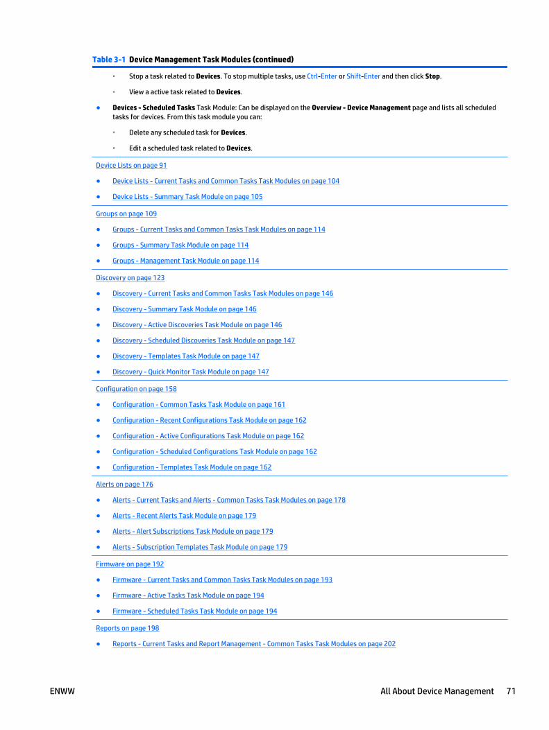
Table 3-1 Device Management Task Modules (continued)
◦ Stop a task related to Devices. To stop multiple tasks, use Ctrl-Enter or Shift-Enter and then click Stop.
◦ View a active task related to Devices.
● Devices - Scheduled Tasks Task Module: Can be displayed on the Overview - Device Management page and lists all scheduledtasks for devices. From this task module you can:
◦ Delete any scheduled task for Devices.
◦ Edit a scheduled task related to Devices.
Device Lists on page 91
● Device Lists - Current Tasks and Common Tasks Task Modules on page 104
● Device Lists - Summary Task Module on page 105
Groups on page 109
● Groups - Current Tasks and Common Tasks Task Modules on page 114
● Groups - Summary Task Module on page 114
● Groups - Management Task Module on page 114
Discovery on page 123
● Discovery - Current Tasks and Common Tasks Task Modules on page 146
● Discovery - Summary Task Module on page 146
● Discovery - Active Discoveries Task Module on page 146
● Discovery - Scheduled Discoveries Task Module on page 147
● Discovery - Templates Task Module on page 147
● Discovery - Quick Monitor Task Module on page 147
Configuration on page 158
● Configuration - Common Tasks Task Module on page 161
● Configuration - Recent Configurations Task Module on page 162
● Configuration - Active Configurations Task Module on page 162
● Configuration - Scheduled Configurations Task Module on page 162
● Configuration - Templates Task Module on page 162
Alerts on page 176
● Alerts - Current Tasks and Alerts - Common Tasks Task Modules on page 178
● Alerts - Recent Alerts Task Module on page 179
● Alerts - Alert Subscriptions Task Module on page 179
● Alerts - Subscription Templates Task Module on page 179
Firmware on page 192
● Firmware - Current Tasks and Common Tasks Task Modules on page 193
● Firmware - Active Tasks Task Module on page 194
● Firmware - Scheduled Tasks Task Module on page 194
Reports on page 198
● Reports - Current Tasks and Report Management - Common Tasks Task Modules on page 202
ENWW All About Device Management 71
Table 3-1 Device Management Task Modules (continued)
● Reports - Report Templates Task Module on page 203
● Reports - Archived Reports Task Module on page 203
● Reports - Data Collection - Management Task Module on page 203
● Reports - Data Collection - Templates Task Module on page 204
● Reports - Scheduled Reports Task Module on page 204
Device Management Options
Configuration options can be set for many functional areas within the Device Management view. For moreinformation, see Device Management Configuration Options on page 51.
Device Tabs on Device List Pages
When you select a device list, a group, or a filtered list, the lower portion of the page displays device tabs thatprovide additional functionality that can be performed on the devices selected in the displayed list:
● Status Tab on page 73: shows the status of the selected device or devices depending on list selection.
● Config Tab on page 74: allows device configuration for one or more devices, depending on the currentselection in the device list.
● Alerts Tab on page 76: shows alert subscription and template tools for a single device or multipledevices, depending on list selection.
● Groups Tab on page 77: lists devices that have been selected in the list and their groups (if any). Alsoallows easy access to add devices to an existing or new group.
● Reports Tab on page 77: allows easy access to report functionality for the selected device or devices.
● Supplies Tab on page 78: displays supplies information for the selected device or devices. Links arealso provided for you to shop online for supplies.
● Storage Tab on page 79: controls secure disk erase and disk initialize operations on either singledevice or multiple devices, based on the list selection.
● Applications Tab on page 81: lists, adds, and removes device based application files.
● Capabilities Tab on page 83: provides information about device features and capabilities.
● Troubleshoot Tab on page 84: provides information to allow you to troubleshoot one or more devices.
● Firmware Tab on page 84: updating is performed on either a single device or multiple devicesdepending on list selection (printer and HP Jetdirect firmware updating is available).
Showing and Hiding Device Tabs
The device tabs are displayed in the lower portion of any device list page to provide you with more detailedinformation about the devices. The device tabs are enabled by default but can be disabled at any time. Theadvantage of displaying the device tabs is to enable quick access to all device data by simply selecting thedevice in the device list and then clicking on the desired tab.
To hide the device tabs, use the Hide Device Tabs tool (the up/down arrow button on the toolbar on anydevice list page). This offers more room to display the device list itself. Hiding device tabs can also reducenetwork traffic and improve performance while working with large lists of devices.
72 Chapter 3 Device Management ENWW
Status Tab
● Parts of the Status Tab Page
● Related Application Options for the Status Tab
Device status can appear for a single device or multiple devices depending on list selection. Device statuspolling rates can be altered for both multiple and single status modes. The number of devices that canconcurrently display status through Status tab is limited to ten by default but can be increased or decreased(Configure the Polling Options for Device Lists on page 53). These settings can be accessed in Tools >Options > Device Management > Status.
The Status tab shows real-time status messages and graphics that indicate device issues for the selecteddevice or devices. While the status tab is being shown, the device status is updated regularly. Use the Statustab to quickly assess the current status of one or more devices.
The polling rate of the devices is set in Tools > Options > Device Management > Device Polling (DevicePolling Configuration Options on page 52).
The Status tab has three possible views:
● Single device view (most common): When a single device is selected, the single device view is shown.The toolbar on the Status tab links to the Embedded Web Server for the selected device (if the devicesupports this feature). Device identification information such as device model, host name, IP address,and system contact information is also displayed (as requested through the top menu bar on View >Preferences > Device Identification). Current supply levels, including the name of the consumable anda percentage level are shown. Additional information on all supplies is available on the device’sSupplies tab at the bottom of any device list.
● Multiple device view: When between 2 and 10 devices are selected, the multiple tiled view is shown.Device identification information such as device model, host name, and IP address is also displayed.Current supplies levels are shown. Additional information on all supplies is available on the deviceSupplies tab.
The number of devices shown is determined by the configuration setting in Tools > Options > DeviceManagement > Device Tabs > General (Configure the General Options for Device Tabs on page 57). Ifthe multiple device view limit is set to 5, and you have more than 5 devices selected, the view changesfrom individual statuses (for each device) to a status summary for all selected devices.
● Composite device view: When more than 10 devices are selected, the composite view is shown. Thenumber of selected devices is shown along with how many are in an OK, Error, or Caution state on thedevice Status tab at the bottom of any device list.
In the Status tab, you can select fields from the device information section and click Ctrl-C.
Parts of the Status Tab Page
Options on the Status tab page include:
● For single device view:
◦ Embedded Web Server (only enabled in Single device view): Brings up a web browser that takesyou to the device’s Embedded Web Server, if the device has one.
◦ Configure Page: Shows the Config tab; you can change or add configuration information fordevices.
◦ Online or Offline (only enabled in Single device view): Shows whether the selected device is onlineor offline. You can actually change the status for the device remotely using this option.
● For multiple device view (2-10 devices):
ENWW All About Device Management 73
◦ Configure Page: Shows the Config tab; you can change or add configuration information fordevices. From the Customize Status Tab page, you can select multiple options to be displayed.While it is convenient to have the configuration information displayed, selecting a lot of theoptions could potentially impact polling time.
● For composite device view (over 10 devices):
◦ Configure Page: Shows the Config tab; you can change or add configuration information fordevices. From the Customize Status Tab page, you can select multiple options to be displayed.While it is convenient to have the configuration information displayed, selecting a lot of theoptions could potentially impact polling time.
Parts of the Status tab page include:
● Single device view (one selected device):
◦ Status: Shows the status of the selected device.
◦ Information: Shows device identification information as requested through the top menu bar onView > Preferences > Device Identification.
◦ Front Panel Messages: Shows the front panel message currently displayed on the selected device.
◦ Supply levels: Shows the ink levels remaining for the selected device.
● Multiple device view (2-10 selected devices):
◦ Status: Shows the status of the selected devices.
◦ Information: Shows device identification information as requested through the top menu bar onView > Preferences > Device Identification.
◦ Front Panel Messages: Shows the front panel message currently displayed on the selecteddevices.
◦ Supply levels: Shows the ink levels remaining for the selected devices.
● Composite device view (11 or more selected devices):
◦ Status summary: The number of selected devices is shown along with how many are in an OK,Error, or Caution state.
Related Application Options for the Status Tab
The following configuration options can be set for polling devices.
● Configure the Background Polling Options on page 52
● Configure the Polling Options for Device Lists on page 53
● Configure the Polling Options for Device Tabs on page 54
Config Tab
● Parts of the Config Tab Page
● Configuring My Settings
The Config tab allows device configuration for the selected device or devices. A list of configuration items isdisplayed and is based on the configuration items supported for the devices selected. If one has the correctpermissions, they can change one or more configuration items and apply the settings to the device or devicesselected. If one does not have the correct permissions, they can only view the configuration items.
74 Chapter 3 Device Management ENWW
If a single device is selected, the configuration items in the tab are shown with the current device settings. Ifmultiple devices are selected, configuration items in the tab are shown with unspecified or blank settings.The list of configurable options varies by the devices selected. With multiple devices selected, allconfigurable items will probably not apply to all devices. Only settings that apply to a device will be set onthat device. Some options may be repeated multiple times because different settings are supported ondifferent devices. If it is not clear which device or device model a particular setting applies to, holding themouse over the name in the configuration settings displays a tooltip with additional information.
Parts of the Config Tab Page
Features on the Config tab page include:
● Customize: Create or view your personalized list of favorite configuration settings in the My settingscategory; this provides fast access (Configuring My Settings on page 75).
● Apply Template: Select a previously created configuration template to apply to the currently selecteddevices.
● View History: Displays a list of recent configurations that have occurred on one or more of the selecteddevices (View Configuration History on page 165).
Options on the Config tab page include:
● Settings category tree: Configuration items are organized into categories to make them easier to find.Within each category, items are sorted alphabetically. My Settings is a special category that can bedefined according to each user’s preference (Configuring My Settings on page 75).
● Configuration settings: Make changes to device configuration settings in this section. Each item youchange should show a check mark automatically, indicating that it will be included in this configuration.You can manually uncheck items to reset their values and exclude them from the configuration. Anychanges made to these settings will not take effect until they are applied and confirmed.
● Refresh: Gets the current settings from a single device, or the unspecified settings for multiple devices.Any pending changes which have not been applied will be lost.
● Save as Template: Captures the selected configuration in an HP Web Jetadmin configuration template.You can use templates for the following reasons:
◦ A backup of the device configuration is needed to manage maintenance and risk.
◦ A device configuration is deemed as “release accepted” and a template is needed to configureother devices with like-settings.
Schedule: Schedule this configuration for later (Schedule a Device Configuration on page 166).
Apply: Apply all of the settings to the device or devices now.
The configuration template only captures configuration options that are selected.
Configuring My Settings
My Settings allow you to group commonly used configuration items in one place, so they are easy to workwith. You can configure, edit, or delete options from My Settings. You can access My Settings from theConfig tab in any Device List (and then click Customize), by right-clicking on any configurable item (forexample, in the Create Configuration Template wizard).
After the Edit My Settings List is displayed, select the configuration option by highlighting it and clicking thearrow buttons between the two lists. To display the options in My Settings, check the Show ‘My Settings’box. To save your changes, click OK.
ENWW All About Device Management 75
Alerts Tab
● Parts of the Alerts Tab Page
The Alerts tab allows easy access to alerts settings for a particular device or set of devices. Device alertsprovide the ability for the device to proactively notify you when a problem occurs with the device.
You can set alerts using the Alerts tab or by selecting Alerts from the menu at the left. Using the Alerts tabcan be faster since you have already selected the device or devices.
The Alerts tab has two possible views:
● Single device view: The current set of subscribed alerts is displayed. You can subscribe to alerts,change alert subscriptions, or remove alert subscriptions.
● Multiple device view: A summary view of how many devices have alerts subscriptions and how many donot. The same quick access to alerts subscriptions, change alert subscriptions, or remove alertsubscriptions is provided.
Parts of the Alerts Tab Page
Options on the Alerts tab page include:
● Group By: The different ways you can choose to group alerts:
◦ Device: Displays devices that can be individually expanded to show each applied subscription andcorresponding Alerts detail.
◦ Subscription: Displays subscriptions by name that can be individually expanded to show devicesto which the subscription has been applied.
◦ Solution Type: Displays one or any of the three types of Alerts that have been configured. Thesecan be expanded to show individual subscriptions and devices to which the subscription has beenapplied.
● + (Expand All): View detail.
● - (Collapse All): View summary information only and no detail.
● Subscribe: Create an alert subscription.
● Apply Subscription Template: Use alert subscription settings to apply to additional devices. The AlertHistory option allows you to view the alerts history for the selected set of devices.
● Alert History: View alerts history; can group by device or by alert.
Parts of the Alerts tab page include:
● Device Model
● IP Hostname
● IP Address
● Advanced Settings
NOTE: There are two threshold settings that can be set through Advanced Settings; Count thresholdand Percent threshold. When Count threshold is enabled, the Alert will trigger as the increasing devicecounter matches the value (number) applied here. This is only visible when Page Count Alerting isenabled.
Percent threshold supplies a common threshold value (percentage) that can apply to threshold Alerts.This is a decreasing percentage and is set on an integer value. This is a percentage based on decreasingsupplies. This setting is only applicable to supplies that are depleting or depleted and need replacing.
76 Chapter 3 Device Management ENWW
● Notification Type
● Subscription Type
● Linked to Template
This page displayed is identical to the page displayed when you select Alerts - All Subscriptions in the leftnavigation pane (All Subscriptions on page 191).
Features on the Alerts tab page include:
● Save As Template: Save the current settings as an alerts template (Create Alert Subscription Templateson page 185).
● Unsubscribe: Remove devices from this alerts template (Edit Alert Subscription Templateson page 188).
● Edit Subscription: Make changes to an alerts subscription (Edit Alert Subscription Templateson page 188).
Groups Tab
● Parts of the Groups Tab Page
This tab reflects the group or groups to which a device has membership, when a single device is selected. Thetab re-displays all selected devices from any device list showing all columns specified in View >Preferences > Device Identification, and the Groups column when multiple devices are selected.
These devices will be added to any group created from the Groups tab, Add devices to group, or Add devicesto new group. In the single device mode, Remove From Group can be used to remove the selected devicefrom any manual group.
Parts of the Groups Tab Page
Parts on the Groups tab page include:
● Add devices to group: Easily add devices to an existing group.
● Add devices to new group: Conveniently create a group and immediately add devices to it.
Columns on the Groups tab page include:
● Group: Lists the name of the group for the selected devices.
● Description: Shows the description of the corresponding group as entered while creating a group withthe Create new device group Wizard or while editing a group with the Edit device group wizard.
● Contact: Shows contact information of the corresponding group as entered while creating a group withthe Create new device group Wizard or while editing a group with the Edit device group wizard.
Features on this page include:
● Remove From Group: Remove a device from the selected group (Remove Devices from a Manual Groupon page 118).
● View: View the devices in the selected group (View a Device Group on page 122).
NOTE: You must select a group before clicking View. If you are in a group and click View in the Groupstab, you must have a row selected with a group other than the one you are in.
Reports Tab
● Parts of the Reports Tab Page
ENWW All About Device Management 77
The Reports tab allows easy access to report functionality for a device or set of devices.
The two main areas of this feature allow you to access the two main reporting tasks:
● Data Collection: Must be enabled for devices to ensure the raw data is present to generate reports.Turning on data collection (by checking the check box and clicking Apply) enables this process. The JobData collection option enables the Jobs by user: color/mono report. The Device Data collectionenables the Device pages: color/mono report.
● Report Generation: Select the type of report to generate.
Parts of the Reports Tab Page
Parts on the Reports tab page include:
● Group By: The different ways you can choose to group data:
◦ Device: Orders the tab-list by each device displayed in the list selection. Expanding the list showseach device and its collection state for each data collection type.
◦ Data Collection: Orders the tab-list by data collection type and shows devices beneath each.
◦ Enabled: Shows two groups of devices. One is Enabled which are devices that have by-user datacollection enabled. The other one is Disabled, which are devices that do not have by-user datacollection enabled.
◦ None: Shows a tab-list of all devices selected with their data collection states appearing withincolumns.
● + (Expand All) or - (Collapse All): show all details or show only summary information.
● Add devices to data collection: Add devices to a data collection that have been defined (Add Devices toData Collection on page 211).
● Apply data collection template: Apply a data collection template (Apply a Data Collection Templateon page 214).
● Generate report: Produce a report after data collection has completed (Generate Reportson page 222).
● Schedule report: Schedule this report to be generated at a specific time (Schedule a Reporton page 234).
Supplies Tab
● Parts of the Supplies Tab Page
● Shop for Supplies
The Supplies tab page provides a quick way to let you review supplies information on a device or set ofdevices. The devices selected to view supplies information do not have to be tracked for supplies usage.
Parts of the Supplies Tab Page
Options on the Supplies tab page include:
● Group By: Controls how the supplies information is presented: by device, urgency, HP part number, ornone.
◦ Device: Shows devices in a collapsed state. Expanding one or more devices reveals supply detail.
◦ Urgency: Groups the devices by Out, Warning and OK supply status categories. Expanding thesereveals device and supply detail.
78 Chapter 3 Device Management ENWW

◦ Part number: Groups the devices by collapsed supply part number categories. Expanding thesereveals device and supply detail.
◦ None: Reveals supply detail in an expanded device list.
● View: Choose between two views of the supplies data: the default view or the details view, whichincludes serial number of the supply, install date, and last used date.
● + (Expand All): View detail.
● - (Collapse All): View summary information only and no detail.
● Shop for supplies online: Easy access to HP SureSupply to shop for all supplies or just needed supplies(the default). After this selection is made, you are connected to the HP SureSupply web site with eitherneeded or all supplies categories pre-selected to order. You are notified that information will betransferred to the HP SureSupply web site and can approve or disapprove of the information being sentto that web site. For more information about Shop for supplies, see Shop for Supplies on page 79.
● Show all and Show only needed: Turn on or off supplies tracking. When a device is tracked for supplies,the device is automatically included in the supplies needed list when supplies are needed. Turningtracking off on the device causes the product to never include the device in the supplies needed list.
NOTE: The Show only needed state is a toggle with the Show all state.
● Print shopping list (icon): prepares a printout of the device list as it is currently displayed.
Shop for Supplies
In any device list, you can select a device or group and then select the Supplies device tab. (If the device tabsare hidden, see Showing and Hiding Device Tabs on page 72.) Supplies you need to order can be included onthe Supply Ordering report if you chose predictive settings. Proactive supplies alerts sends an email with asupply ordering report when a supply meets a threshold.
After you run this report, you can access the HP SureSupply web site to actually order your supplies. (SeeSupply Ordering on page 207.)
Storage Tab
● Parts of the Storage Tab Page
● Device File System Password
Storage management functionality is used to manage fonts, macros, and objects on device storage facilitiessuch as disk or flash devices. This functionality can be viewed from any device list with one or more devicesselected and then choosing the Storage tab.
All selected devices are displayed in the Storage tab list with Device Model, IP Hostname, and IP Addressdefined. Used space and Read/Write accessibility are displayed for each device in the list. In addition,grouping controls exist for multiple devices enabling a variety of storage analysis and storage configurationaccess.
Parts of the Storage Tab Page
● View
● Templates
● Repository
The Storage tab displays information about the devices selected in the device list. The following sectionsdescribe the options on the Storage tab.
ENWW All About Device Management 79
View
You can use the View option to select the type of information displayed on the Storage tab for the selecteddevices.
● Media: This option lists the storage media on the selected devices. If the Storage Device count is 1 orgreater, the mouse-over tool tip displays a table of all the storage media on the device. The followingoptions are available in this view:
◦ Secure Storage Erase: Starts the devices secure storage erase action. One of three secure modescan be set for the storage erase action. These modes are Non-secure Fast Erase, Secure FastErase, and Secure Sanitizing Erase. The extent of security in the secure erase feature on thedevice will depend on device model and firmware. See device documentation regarding SecureStorage erase features for more details. An option to enable write-protect can be set to leave thedevice in read-only mode once secure storage erase has completed. This feature can be scheduledas a one time or recurring operation.
◦ Initialize File System: Causes the device user-directory structure to initialize. The file system willvary depending on device or storage type; please see device-specific documentation. This featurecan be scheduled as a one-time or recurring operation.
◦ Write Protection: Enables or disables write functionality on the selected storage facility. Thismakes a device read-only or read-write capable.
◦ Erase Customer Data: Starts the Erase Customer Data wizard. This wizard removes any jobinformation that is stored on the device, but does not remove any device configuration settings.The device cannot be used while the erase operation is in progress. You can schedule the eraseoperation to occur at a specified time.
You can choose the Non-secure fast erase, Secure fast erase, or Secure sanitizing erase modefor the erase operation. The Secure sanitizing erase mode overwrites the data three times andcan take several hours to complete for large hard disks.
NOTE: For more information about HP FutureSmart devices and hard disk security, see theHP FutureSmart Firmware Device Hard Disk Security white paper. This white paper is available fromthe HP Support Center.
◦ Use Drive: If a device has more than one drive installed, enables you to select the drive whereconfiguration files, stored jobs, and temporary files are stored, and move existing customer datato that drive. You cannot move configuration data to a RAM drive because all data on a RAM driveis lost when the drive is turned off and then turned on. You can create a schedule to run the UseDrive operation one time or on a recurring basis.
◦ Erase Drive: Enables you to completely erase a drive. This process does not preserve any data.You can erase only one drive at a time. The Secure Erase option selects the most secure erasemethod available for the selected drive. The Cryptographically Erase option is performed only onsecure drives. This option resets the encryption key, prevents access to the data, turns the driveoff and then on, and re-encrypts the drive with new keys. You can create a schedule to run theErase Drive operation one time or on a recurring basis.
◦ Set Encryption to AES_128: Erases all of the data on the SSD drive. The device automatically turnsoff and then turns on. When the device turns on, the encryption level is set to AES_128.
◦ Set Encryption to AES_256: Erases all of the data on the SSD drive. The device automatically turnsoff and then turns on. When the device turns on, the encryption level is set to AES_256.
● Fonts and Macros: This option displays the number of fonts and macros installed on the device. Themouse-over tool tip displays a table of all the fonts and macros installed on the device. The followingoptions are available in this view:
80 Chapter 3 Device Management ENWW
◦ Install: Installs a font or macro on the selected device. (See Install Fonts and Macros on Deviceson page 248.)
◦ Remove: Removes the selected fonts and macros from the device, but does not remove them fromthe Storage Repository. (See Remove Font and Macro Files from Devices on page 248.)
◦ Print Font/Macro: Prints the selected fonts and macros. (See Print Font/Macro on page 248.)
● Resident Fonts: This option displays the number of resident fonts on the device. The mouse-over tooltip displays a table of all the resident fonts on the device.
● Disk Jobs: This option displays the number of stored jobs currently on the device. The mouse-over tooltip displays a table of the stored jobs on the device. The following options are available in this view:
◦ Delete: Deletes the selected print job.
◦ Print Disk Job: Prints the selected print job. If the print job is secured by a PIN, you must type thecorrect PIN in order to print the job. You can enter only one PIN. If you select more than one PIN-protected job and the jobs have different PIN values, you can print only one. HP recommends thatyou select only one private print job at a time to avoid this restriction.
Templates
You can use the Templates option to access the Storage > Templates page. (See Storage Templateson page 249.)
Repository
You can use the Repository option to access the Storage > Repository page. (See Storage Repositoryon page 246.)
Device File System Password
If a file system password exists on the device and if it is not captured in HP Web Jetadmin’s Credential Store,you will be prompted for the password when attempting to perform any configuration action. Device filesystem passwords can be configured on the devices from HP Web Jetadmin. When these are configured, theyare also placed into the Credential Store. Global file system credentials can be added to HP Web Jetadminthrough Tools > Options > Shared > Credentials > Device > File System (Manage the Global File SystemPasswords on page 50). These are used when no password exists in the store and one is required by thedevice.
Applications Tab
Device applications can be downloaded and executed onto devices to facilitate an embedded runtimeenvironment. These applications support a variety of operations and run much like programs and services onPCs. Applications can be developed to provide additional functionality such as address books, digital sendfeatures, and more. One key application is the Manager application that must be loaded onto the devicebefore HP Web Jetadmin can view and modify applications.
One or more devices selected from any list will appear under the Applications tab. Each device will appearwith any resident applications. Again, the Manager application must be loaded onto the device beforeHP Web Jetadmin will list resident applications. Some device models have the Manager applicationembedded into firmware making it resident.
NOTE: Some HP Web Jetadmin configuration options require device applications. These include allconfiguration options for either EWS or digital send functionality. When this type of configuration is eitherviewed or changed via HP Web Jetadmin software, device applications are automatically installed.
Features on the Applications tab page include:
ENWW All About Device Management 81
● Install Manager: For devices that do not already have the Manager application installed or do not havea firmware embedded Manager application, the Install Manager function must be used. Devices that donot have the Manager installed will appear in the Applications list with the indication (Manager notinstalled). To install the Manager, select the device or devices from the Applications list and chooseInstall Manager.
● Install Applications: Once the Manager application is installed on the device, other residentapplications are listed. New device applications can be removed or added at this time. InstallApplications is used to push device applications onto the device.
● Application Repository: Device applications that are available on the HP Web Jetadmin host system canbe viewed by using Application Repository. When launched, this interface lists all applications that areready to be installed on devices. You can also use the following to manage the applications:
◦ Upload: Upload application files from the client host onto the HP Web Jetadmin host.
NOTE: Files that can be uploaded must be .jar files with .phx metadata files. Most .jar chailetshave the .phx file contained within them, extractable using utilities such as WinZip. If a .jar file isselected for upload that has not had the .phx file extracted, there is an error message indicatingthat a Metadata file is required.
◦ Delete: Remove applications from the HP Web Jetadmin host.
● Credentials: Device credentials can be used to protect against unauthorized downloading andmanipulation of device resident applications. The EWS password is used for this purpose and ismanaged within the HP Web Jetadmin Credential Store. This device credential can also be set on one ormany devices through HP Web Jetadmin Configuration on page 158.
Solutions Tab
● Editing Solutions
● Install Managers
The Solutions tab page shows information about each selected device within the device list, includingwhether the device has its Application Manager and Solution Manager installed on it. Both are needed toinstall chailets and .NET applications. The Application Manager is also required to install Solutions (seeSolutions Repository on page 253). Information is also included about how many applications (chailetsand .NET applications) and solutions are installed on the device. You can refresh this information by clickingRefresh.
Features on the Solutions tab page include:
● Repository: Accesses the Solutions Repository (see Solutions Repository on page 253).
● Apply Template: Select a template and then apply it to the selected devices (see Applying a SolutionsTemplate on page 258).
● Refresh: Refreshes the device information.
● Install Manager: Enabled if one or more devices is missing either its Application Manager or SolutionManager. Clicking the button launches a wizard that allows you to select which manager to install on allselected devices (see Install Managers on page 83).
Editing Solutions
● Description: custom description of the solution.
● Application URL: specifies where the solution is located, and identifies a credential that can be appliedto access the location.
82 Chapter 3 Device Management ENWW
● Configuration URL: specifies where a configuration file is located, and identifies a credential that can beapplied to access the location. The configuration file is used to configure the solution.
● License URL: specifies where a license file is located, and identifies a credential that can be applied toaccess the location. The license file is used to grant access to various functionality within the solution.
You can edit the Configuration URL and License URL properties for one or more solutions using the EditSolution wizard.
1. From the Solutions tab, select a device and click Edit. The Edit Solution wizard is started with theSelect options page displayed.
2. Select an existing template or manually specify options.
3. To edit the solution immediately, click Next.
-or-
To schedule the edit for another time, click Schedule and then Next.
4. Select at least one solution and click Next. The Edit settings page is displayed with a list of solutionsthat have been selected.
5. If you select one of the displayed solutions, its Configuration URL and License URL settings aredisplayed in the Settings group box on the right side of the wizard page.
6. Specify new Configuration URL and License URL settings and then click Activate Choice for Solution.The selected solution will have its associated State column changed to Modified. Click Next.
7. If you are installing the solution now, the Confirm page is displayed.
If you chose to schedule the edit of the solution, the Specify schedule options page is displayed. Assigna name and then specify a date, time, and recurrence for the edit.
Click Next. The Confirm page is displayed.
8. Click Edit. The Results page is displayed.
9. Click Done.
Install Managers
The Install Manager wizard installs the Application Manager, the Solution Manager, or both on one or moredevices. Follow these steps:
1. Select a device or devices within the Solutions tab.
2. On the Solutions tab page at the bottom of any device list, click Install Managers. The Install Managerwizard is started with the Select page displayed.
3. Select which manager or managers to install on the devices and then click Install. The Results page isdisplayed.
4. Click Next. The Confirm page is displayed.
5. Click Done.
Capabilities Tab
The Capabilities tab page shows a list of capabilities information for either a single device or multipledevices, depending on the devices selected in the device list. Device capabilities are displayed in twocolumns: capabilities name and capabilities value. An alphabetic sort can be done on the capabilities name.
ENWW All About Device Management 83
Troubleshoot Tab
● Parts of the Troubleshoot Tab Page
The Troubleshoot tab page provides several features that can be used to remotely control devices andanalyze other areas for troubleshooting purposes. The features available change depending on the device ordevices selected in the device list.
Parts of the Troubleshoot Tab Page
Options on the Troubleshoot tab page include:
● Embedded Web Server: Available only when a single device is selected in the device list; launches theselected device’s resident http interface.
● Online/Offline: Available only when a single device is selected in the device list; remotely toggles theselected device between online and offline.
● HP Support: Available only when a single device is selected in the device list; launches the product pagecontent from www.hp.com for the selected device. HP Instant Support pages are launched when thedevice supports this type of www.hp.com content.
● Reset Device: allows you to perform various reset options on one or more devices (see Reset DeviceWizard on page 87).
● Print Test Page: Available for both single and multiple device selections on the device list; can launch alocal device configuration page or send a file from the client to host to the device’s 9100 print port.
The file must be in a file format that the printer natively knows how to print; this varies by printer. Forexample, most printers can accept simple .txt files and pjl formatted files. Some printers can nativelyprint pdf files, and so forth.
Parts of the Troubleshoot tab page include:
● Detailed status: Available for both single and multiple device selections on the device list.
Single device selections: HP Web Jetadmin reflects all status messages for the selected device. This isdifferent from a single device status view where only the most severe message is displayed.
Multiple device selection: HP Web Jetadmin reflects status counters for selected devices in the devicelist.
● Troubleshooting tools: Provide historical information for single or multiple device selection andinclude:
◦ Recent Alerts: Shows all recent alerts for the device selected.
◦ Recent Configurations: Shows the recent configuration for the device selected.
◦ Firmware Updates: Shows all available firmware updates for the selected device.
Firmware Tab
● Parts of the Firmware Tab Page
The Firmware tab page can be activated on any device list. Both single and multiple devices can be displayedwithin this tab.
If you want to upgrade firmware from a device list, right click on the device and select Upgrade firmware.This will start the Upgrade Firmware wizard; from within this wizard, you can schedule the upgrade.
84 Chapter 3 Device Management ENWW
Parts of the Firmware Tab Page
Options on the Firmware tab page include:
● View: The following views are available on the Firmware tab page:
◦ Jetdirect Firmware: Displays detailed information about the status of the HP Jetdirect firmwareand whether any upgrades are available in the repository.
◦ Printer Firmware: Displays detailed information about the status of the printer firmware andwhether any upgrades are available in the repository.
◦ Summary: Displays summary information about the firmware status for the selected devices.
NOTE: From the Jetdirect Firmware or Printer Firmware pages, actions can be launched. When one ormore devices with upgrades available are selected, the Update button is enabled. When clicked, it willlaunch the Firmware Upgrade wizard with the given devices.
● Repository: brings you directly to the Firmware Repository on page 196.
NOTE: You can change the default for the number of retries HP Web Jetadmin will attempt before stopping(Configure the Settings for Firmware Upgrades on page 68).
NOTE: When HP Jetdirect firmware upgrades, a device can be left in short stack if it is accidentallydisconnected during the upgrade or if some other fatal error occurs. HP Web Jetadmin will detect that errorcondition and attempt the upgrade again to ensure the device is not left in a bad state. A condition onHP Jetdirect cards is NLS Missing which happens if the card needs to be upgraded once for English, and thenagain for localized languages; HP Web Jetadmin will detect this situation as well.
Copy Template Wizard
Throughout Device Management view, templates can be created and managed to save you time and provideconsistency. Templates contain configuration preferences (that vary by template type) and can be applied todevices or groups. Templates are available in Configuration, Alerts, Discovery, Data Collection, and ReportGeneration. Templates with a locked icon next to them are system templates that cannot be edited; thesetemplates can be copied if you want a template with similar settings.
NOTE: In the Application Management view, templates can be created for Role Templates (RoleTemplates on page 276).
After a template has been created, it can be copied to create a new template and then changes can be made.This is useful if you need a template similar to an existing one.
To copy templates, perform the following steps:
1. In the left navigation pane, right-click the area for the template (Configuration, Alerts, Discovery, DataCollection, and Report Generation) and select Copy template. The Copy Template wizard is startedwith the Specify template name page displayed.
2. Select the template to copy from the Template drop-down list.
3. In the New template name field, type the name of the new template.
NOTE: The original template will remain unchanged.
4. Click Next. The Confirm page is displayed showing the original template name and the new templatename just created.
5. If the new template name is correct, click Copy Template. The template will be copied to its new name.
ENWW All About Device Management 85
6. The Results page is shown. Click Done.
7. Make changes to the new template by following the appropriate steps:
● Edit a Configuration Template on page 172.
● Edit Alert Subscription Templates on page 188.
● Edit a Discovery Template on page 156.
● Edit a Data Collection Template on page 215.
● Edit a Report Template on page 241.
Export and Import Device Configuration Templates
In an environment that has multiple instances of HP Web Jetadmin, you can create device configurationtemplates in one instance, and then import them into the instances that are running on different servers.However, to import device configuration templates, each server must run the same version ofHP Web Jetadmin.
Export device configuration templates
1. In the Device Management navigation pane, expand Configuration.
2. To export multiple templates, right-click Templates, and then select Export configuration templates.The Export Templates wizard starts. On the Select template page, select the templates, and then clickthe Next button.
-or-
To export one template, expand Templates, right-click the template, and then select Export. TheExport Templates wizard starts.
3. On the Specify export options page, enter a password in the File encryption password box. Thispassword prevents unauthorized access to any sensitive data in the template.
4. In the Confirm password box, enter the password again, and then click the Next button.
5. On the Confirm page, verify that the correct templates are listed, and then click the Export button.
6. On the Save as window, navigate to the location to save the template file, enter a name in the File namebox, and then click the Save button.
7. On the Results page, click the Done button.
Import device configuration templates
1. In the Device Management navigation pane, expand Configuration.
2. Right-click Templates, and then select Import configuration templates. The Import Templates wizardstarts.
3. On the Select file page, click the Browse button, navigate to and select the template file, and then clickthe Open button.
4. In the File password box, enter the password that was assigned to the template file when it wasexported.
5. To overwrite an existing template that has the same name, select the Overwrite duplicate templatescheckbox. If you select this checkbox, a warning message appears on the Confirm page.
6. Click the Next button.
86 Chapter 3 Device Management ENWW
7. On the Confirm page, verify that the file name is correct, and then click the Import button.
8. On the Results page, click the Done button.
Reset Device Wizard
You can reset one or more devices. The Power Cycle option can be scheduled.
To reset devices, perform the following steps:
1. In any device list, highlight the device or devices you want to reset and click the Troubleshooting tab.
2. Click Reset Device. The Reset Device wizard is started with the Select a reset option page displayedwith a list of reset options.
3. Choose one of the reset options:
● Power Cycle: sends a power cycle command to devices that support this functionality. This optioncan be scheduled.
● Reset to Factory Defaults: resets a device to its factory defaults on devices that support thisfunctionality.
When a single device is selected, both the Power Cycle and Reset to Factory Defaults options areavailable for the devices that support both options. If multiple devices are selected, both options willalways be available.
4. Only the Power Cycle option can be scheduled:
● Select Schedule and click Next.
● Type the name for the schedule.
● Select the start date and time.
● Select the recurrence.
5. Click Next. The Reset device results page is displayed.
Edit Schedule Wizard
After a schedule has been completed, it can be edited.
To edit schedules, perform the following steps:
1. In Device Management, access the Scheduled Tasks task module. Then highlight the task and Edit.
In Application Management, access the Application Management - Schedule Tasks task module or theWeb Jetadmin - All Active Tasks task module.
2. Highlight the task and click Edit.
3. Click Next. The Confirm page is displayed.
4. The Results page is shown. Click Done.
Mapping
● All About Maps
● Activating the Maps Feature
● Adding a Map Graphic to a Device Group
ENWW All About Device Management 87
● Changing a Graphic Image for a Map
● Placing Devices and Subgroups on a Map
● Placing URLs on a Map
● Viewing Device or Group Status
● Sizing a Map
● Removing Items from a Map
● Removing a Map from a Group
Mapping lets you identify the physical location of devices, device groups, and URLs on a map. You can also setup navigation shortcuts to key items.
There are three general steps to follow to use the Map features:
1. Activating the Maps Feature on page 89
2. Adding a Map Graphic to a Device Group on page 89
3. Placing Devices and Subgroups on a Map on page 89
When all three of these steps have been completed, you can use the Map docking feature and begininteracting with maps (Docking Task Modules and Maps on page 28).
All About Maps
● Devices and Groups
● Hidden Devices and Mapping
Devices in Groups that have been added to maps have specific behaviors that should be considered:
Devices and Groups
Devices in groups and sub-groups have specific behaviors that should be considered:
Devices in Automatic Groups
● If a device that has been placed on the map for an automatic group is automatically removed from anauto group (because it no longer meets the auto group criteria) it is removed from the map but theinformation that is on the map and where it is placed is maintained in case the device is automaticallyadded back into the group in the future. The mapping information will be maintained until the map forthe group is removed, the group is removed, or the device is deleted from HP Web Jetadmin.
● If a device is automatically added to an automatic group (because it meets the auto group criteria) thebehavior depends upon whether or not it was previously on the map. If it was not previously on themap, then it will not be on the map after it is added. If it was on the map when it was automaticallyremoved earlier, then it will be placed back on the map in the same location. If the map has beenchanged in between and the location is now off the map, the map item will be removed from the map.
For more information about automatic and manual groups, see Manual versus Automatic Groupson page 111.
Devices in Sub-groups
● If you remove a sub-group that has been placed on its parent's map, then the sub-group is removedfrom the map and all map information about that sub-group on that map is permanently deleted from
88 Chapter 3 Device Management ENWW

HP Web Jetadmin. For information about sub-groups, see Placing Devices and Subgroups on a Mapon page 89.
● If you change a sub-group that has been placed on its parent's map to have a different parent group,then the sub-group is removed from the original parent group's map and all map information about thatsub-group on that map is permanently deleted from HP Web Jetadmin.
Hidden Devices and Mapping
Hidden devices in HP Web Jetadmin will not be displayed on any map. However, HP Web Jetadmin willcontinue to remember that the device is on those maps and where it was placed unless the map or group withthe device is deleted from HP Web Jetadmin.
When you reactivate a hidden device, it reappears on any maps that contained it when it was hidden. It isplaced in the same location on each map on which it appeared. If the map for the group has changed and thelocation where the device is to be placed is no longer on the map, then the device is permanently deletedfrom that group's map. For automatic groups, the device only reappears on the map if it also reappears in thegroup because it still meets the auto grouping criteria for the group.
Activating the Maps Feature
The Map module must be activated before you can use it.
1. From the top menu bar, select View > Device Modules > Map.
2. If Map is grayed out, it is already active. If it is not grayed out, select it to activate maps.
If you are in a device group with a map, activating it causes the map for that group to appear. If not,then there are no visible changes when this feature activated.
Adding a Map Graphic to a Device Group
Any graphic can be added to a device group. File types must be supported by Microsoft Windows.
1. From the left navigation pane, select All Devices or a group under Groups.
2. Click Configure map in the toolbar. The Configure map dialog is displayed.
3. To add a map to the group, follow the steps on the page. You can also drag-and-drop a graphic onto theright-hand portion of the window to use it as your map graphic.
Changing a Graphic Image for a Map
A graphic image for a map can be changed to a different image. File types must be supported by MicrosoftWindows.
1. Click Configure Map on any device list page. If the group already has a map and the map module isshowing the map for the group, you can access Configure Map by clicking on the Configure Map tool onthe Map toolbar.
2. Click New map. The File Open dialog is displayed.
3. Specify the new graphic file
4. Drag a graphic image and drop it on the picture area of the Configure map dialog.
Placing Devices and Subgroups on a Map
Before you can place devices on a group map, there must be devices in the group (Add Devices to a Groupon page 117). In order to place sub-groups on a group map, the group must have sub-groups.
ENWW All About Device Management 89

The device image is the same image used for that device in device lists. It is centered on the point where youdrop it on the map.
If selecting more than one device, devices are placed on the map at the point where you drop them with eachimage being positioned slightly down and to the right of the previous one. If the automatic positioning placesan image off of the map, the cascading continues in the upper left corner of the map.
A device or a subgroup may only appear on the map once. Once it is on the map, it no longer appears in thelist on the left. Devices may appear on multiple maps. Subgroups can only appear on the map for their parentgroup.
1. Click Configure Map on any device list page. If the group already has a map and the map module isshowing the map for the group, you can access Configure Map by clicking on the Configure Map tool onthe Map toolbar.
2. Select Device or Group from Map Item Type. The devices in the device group are listed.
3. Select one or more devices in the list and drag and drop them on the map where you want them.
4. To move the device or subgroup to a different location on the map, click on it and drag and drop it on itsnew location.
Placing URLs on a Map
1. Click Configure Map on any device list page. If the group already has a map and the map module isshowing the map for the group, you can access Configure Map by clicking on the Configure Map tool onthe Map toolbar.
2. Select URL from Map Item Type. The devices in the device group are listed.
3. Type a name and Web address for the URL.
4. Click on the URL and drag and drop it onto the map where you want it. The item image is placedcentered on the point where you drop it.
5. To move the URL to a different location on the map, click on it and drag and drop it on its new location.
Viewing Device or Group Status
The View mode provides various functionality for maps.
● Device status: The status of a device or a group is only displayed on the map in View mode; it is notvisible in Configure Map. The status is shown on the device icon on the map.
● Selecting devices on a map: Selecting a device on a map also selects it in the device list. If a device is ona map, selecting it in the device list will also select it on the map. Multiple devices can be selected on themap by holding down Ctrl.
● Accessing devices in sub-groups: Selecting a group on the map also selects it in the left navigation paneand displays its device list. If the new group has a map, it is displayed in the map module; if it does nothave a map, the map module is hidden.
● Move up to a parent group: Use Map to move to the parent group by clicking View parent group item onthe map module's toolbar. This selects the parent group in the left navigation pane and switches to thatgroup's device list. If the parent group has a map it is displayed in the map module; if it does not have amap the map module is hidden.
● Go to a URL: Select a URL on the map to launch the browser and take you to that URL.
● Filter device list: Any filter applied to the device list is also applied to the map. For example, if you applythe Color devices filter to the device list, the map no longer shows monochrome devices that have beenplaced on the map. Clearing the filter causes the mono devices to reappear on the map.
90 Chapter 3 Device Management ENWW

Sizing a Map
A map can be resized using one of three methods.
In Edit mode, resize the Configure Map dialog by clicking and dragging a corner of the map graphic.
In View mode, use the drop-down in the Map module and select one of three methods. The images for thedevices, groups, or URLs on the map will move appropriately as the map is scaled to continue to center on thesame point on the map.
● Fit to screen: The map image will fit exactly within the available space of the Map window.
● 100%: The map image is displayed as the actual size of the graphic image that is being used for themap. Depending upon the current size of the map module window, the resulting image may be smalleror larger than the window.
● Custom: You can select the size of the map between 10% of actual size to 200%. Select Custom andthen use the “minus” and “plus” signs to decrease or increase the size of the map. These buttonschange the zoom by 10% each time they are clicked until the limit is reached (at which time the buttonwill be disabled).
Removing Items from a Map
You can remove items from a map without removing the entire map.
1. Click Configure Map on any device list page. If the group already has a map and the map module isshowing the map for the group, you can access Configure Map by clicking on the Configure Map tool onthe Map toolbar.
2. Remove items using one of these methods:
● Click the item to remove and drag it off the map.
● Right-click on the item to remove and select Remove item.
Removing a Map from a Group
You can remove a map from a group with one of the following methods:
● Use Remove map on the toolbar.
● Right-click on the map to remove and select Remove map.
Device Lists● All About Device Lists
● Task Modules for Device Lists
● Related Application Options for Device Lists
● Printing Device Lists
● Deleting Devices from Device Lists
● Refreshing Devices
● Find More Devices
● Add Credentials for Devices
● Resolve Communication Errors for Devices That Have a New IP Address
ENWW Device Lists 91
All About Device Lists
● Pre-Defined Device Lists
● Columns for Device Lists
● Customizing Layouts for Device Lists
● Filters and Device Lists
● Search Device Lists
● Exporting Device Data
HP Web Jetadmin Device Lists and related features such as sorting and filtering lets you easily locate,manage, and analyze device fleets. Batch configuration, fleet upgrades, reporting and other powerfulHP Web Jetadmin features all start with the basic list of devices.
For example, Pete is an HP Web Jetadmin user who understands that all devices of a certain model and in acertain geographical location require firmware updates. These updates are required to enhance the devicefunctionality and increase performance. Using advanced filtering, Pete can get a list of devices that matchboth the model and geographical location criteria. Pete can then export the details from this list and use thecontact information to begin communicating a time frame in which the firmware updates will occur. After atime, the contacts are all aware of the firmware update activity that will happen after hours when mostdevices are not in use. Then, using a device list and firmware updating, Pete can schedule the fleet updatesfor these devices. Later, again using HP Web Jetadmin lists, Pete can view all of the devices that have or havenot completed the firmware update process. A common theme in this scenario is device lists and filtering.(See Filters and Device Lists on page 97.)
To ensure this feature works properly, see System Requirements on page 1.
Pre-Defined Device Lists
The following pre-defined device lists show devices on your network that are not marked as hidden:
● All Devices: Displays a list of all discovered devices.
● Color Devices: Displays a list of discovered devices that support color.
● Error Devices: Displays a list of discovered devices that are in an error state.
● Information Devices: Displays a list of discovered devices that are in an information state.
● New (Last Discovery): Displays a list of devices that were discovered for the first time by the lastdiscovery.
● New (Manual): Displays a list of discovered devices that are considered new. Devices are considerednew when they are first discovered. The devices remain in this state until you explicitly acknowledgethem. Acknowledging devices can be done by right-clicking any selection of devices in any devices list.
● New (Time Period): Displays a list of devices that were discovered for the first time within the last 14days. You can set the number of days in Tools > Options > Device Management > Device Filters > NewDevices Filter. For more information, see Configure the Number of Days that Devices are ConsideredNew on page 57.
● Non-unique Devices: Displays a list of discovered devices that cannot be uniquely identified.
HP Web Jetadmin uses a combination of the device serial number, model name, and model number tocreate a unique identification for each device it discovers and adds to the All Devices list. If a devicecannot supply any of these attributes, HP Web Jetadmin adds the device to the All Devices list, butmarks the device as non-unique. Some features, such as Device Utilization Data Collections, do notfunction with non-unique devices.
92 Chapter 3 Device Management ENWW
● PC-Connected Devices: Displays a list of discovered devices that are connected to a PC rather thanconnected directly to the network.
● Ready Devices: Displays a list of discovered devices that are in a ready state.
● Ungrouped Devices: Displays a list of discovered devices that are not assigned to any group.
● Warning Devices: Displays a list of discovered devices that are in a warning state.
NOTE: If the Device Model column is blank, that device has a model name that HP Web Jetadmin does notrecognize. If Unknown (Disconnected) appears in the Device Model column, the HP Jetdirect print serverdoes not have a printer connected to it.
Groups lists are the Device Lists that display when a group is selected. These lists can be searched or filteredjust as the All Devices list can be searched or filtered (Search Device Lists on page 101 or Filters and DeviceLists on page 97). For more information about Groups, see Groups on page 109.
Columns for Device Lists
● Complex Data in Device Lists
● Columns Dependent on HP Web Jetadmin Data
● Columns Dependent on HP Jetdirect Data
● Statuses on Device Lists in HP Web Jetadmin
● Manipulating Columns in Device Lists
● Steps for Adding or Removing Columns for Device Lists
The columns in device lists contain simple data or complex data. HP Web Jetadmin obtains most of the datathat appears in these columns by querying the devices, but some of the data is specific to HP Web Jetadmin.You can use the columns to sort and customize the device lists.
There are numerous columns in HP Web Jetadmin. This number continually increases as new devices,functionality, and plug-ins are released.
Complex Data in Device Lists
Complex columns contain a summary of the data in a grid format. The heading of a complex column containsan icon that indicates an advanced tooltip is available. Hold the cursor over the data in the grid to activate theadvanced tooltip feature and display more information about the data. You can also display the data incomplex columns as separate columns.
The advanced tooltip displays for 1 minute or until you move the cursor outside of the tooltip. Every time youmove the cursor within the tooltip, the 1 minute starts over. The information in the tooltip can also becomplex. In this case, the tooltip displays a summary of the data and an icon that indicates more data isavailable. Hold the cursor over the data in the tooltip to activate another advanced tooltip that displays thenext level of data.
Columns Dependent on HP Web Jetadmin Data
Some column data is internal to HP Web Jetadmin and is not obtained from the device, such as device statusor other data specific to the local application. Examples of these columns dependent on HP Web Jetadmindata are:
ENWW Device Lists 93

● User Defined Settings: Custom columns that can be created by users and then populated with data thatis only resident on the application. (In previous versions of HP Web Jetadmin, this used to be calledcustom fields or custom settings.)
● Acknowledged: Shows if you have defined the device as Acknowledged. Acknowledging devices can bedone by right-clicking any selection of devices in any devices list.
● Credentials Required: Shows requests for required credentials that were not met.
● Discovery Date/Time: Time and date of the last discovery.
● Last Communication: Time and date of the last communication.
● Last Discovered: Time and date of the last discovery that found this device.
● PC-Connected: If a device is locally connected to a PC.
● Status: HP Web Jetadmin status message about the device.
● Severity: Severity rating of status for the device.
● Groups: Shows the group membership for a device, listing ether a single group or the word “multiple”. Ifyou hover-over it with your mouse a listing of all groups is displayed.
NOTE: You can enable two different columns that help track discovery and communication and representinternal device date/time tracking: Last Communication and Last Discovered. These time stamps areupdated whenever a discovery has occurred in which the device was discovered or re-discovered.
Columns Dependent on HP Jetdirect Data
Some columns displayed in device lists in HP Web Jetadmin are dependent on data retrieved fromHP Jetdirect devices:
● Jetdirect Model
● Jetdirect Port
● Jetdirect Revision
IP Hostname and System Name in HP Web Jetadmin Lists
IP Hostname and System Name can both be enabled in HP Web Jetadmin device lists. The IP Hostname isenabled in the Default HP Web Jetadmin device list layout. These two items can be useful but can also beconfusing.
IP Hostname is an element that is populated with a name retrieved from network DNS (Domain NameService). HP Web Jetadmin uses the device IP address and performs what is known as a reverse-lookup; DNSresponds with a name value if one is registered within the service for that particular IP address. Tworequirements exist for HP Web Jetadmin to be able to get a device's IP Hostname: DNS provides reversename lookup based on the IP address, and the device IP address must have a name registered in DNS. IfHP Web Jetadmin performs a name lookup for a device’s IP address and DNS is unable to deliver a result, thevalue Unknown is displayed in the device list's IP Hostname column. HP Web Jetadmin will only showresolvable names in the IP Hostname column.
NOTE: The IP Hostname column is enabled by default. To populate this column, HP Web Jetadmin mustperform DNS lookups. To enable DNS lookups, go to Tools > Options > Shared > Network > DNS. For securityand performance reasons, you can disable DNS lookups.
System Name is an object that is bound to the HP Jetdirect print server. The System Name appears as HostName in the Embedded Web Server (EWS) interfaces for many devices in the networking configuration area.This device bound name, in and of itself, is not resolvable through DNS. When a device’s System Name ischanged to something like “PRTR445” and the DNS name value for a device’s IP address is “lab412”, the IP
94 Chapter 3 Device Management ENWW
Hostname column in HP Web Jetadmin will reflect “lab412”. System Name is simply a device bound objectthat can be changed using HP Web Jetadmin and the device’s EWS but there are cases when it can also beregistered into DNS.
HP Jetdirect print servers have a few different features that can allow the System Name value to becomeregistered into a device’s DNS. In many cases, when devices have their IP address parameters DHCPconfigured, a registration with DNS is possible. This is dependant on both the DHCP system on the network,the HP Jetdirect print server model and firmware revision, and the system name being populated on theHP Jetdirect print server. For more information about DHCP/DNS name registration, see the technicaldocumentation for HP Jetdirect print servers. WINS is another network service that can be used to makeHP Jetdirect print server system names visible through DNS. Many HP Jetdirect print servers are capable ofexposing the System Name via WINS and WINS/DNS linkages can cause these names to be DNS visible andalso appear in the IP Hostname column in HP Web Jetadmin. For more information about IP Hostname andDNS registration, see the technical documentation for HP Jetdirect print servers.
Statuses on Device Lists in HP Web Jetadmin
You can select columns to view on Device Lists from a static list of columns. The various statuses might bedisplayed in those columns include:
● Unavailable: The device does not support the column.
● Undefined: For the HP Jetdirect version when the device is incapable of reporting that attribute.
● Missing: Usually a temporary status until the device communicates its data to HP Web Jetadmin.
Manipulating Columns in Device Lists
You can manipulate columns on the device lists in HP Web Jetadmin:
● Selecting Devices: Selecting a device means performing some action that causes the device to becomeselected which sets up the device or devices for some further action. Click to select one device or Shift+Click to select multiple devices.
● Resize columns: To set the width of a column, click and drag the column marker in the list header to thedesired width. Or, to resize the column to the broadest width required to display the data, double-clickon the column header.
● Sort columns:
◦ To sort the entire device list by a specific column, click in the header for that column. Click again toreverse the sort.
◦ To perform a secondary sort on a list, use Shift+Click on a different column after the initial sort.
◦ To perform additional sorts, hold down Shift while clicking on different column headers.
● Display or hide columns: To display or hide columns, right-click on the column header. The columnsthat are currently displayed have a check mark next to them; the ones that are not displayed (or hidden)have nothing next to them. Click on the columns to display or hide.
● Right-click menus: Various kinds of right-click menus are displayed based on whether something isselected and what list is displayed. For example, if a device is selected on a device list, right-clickingwithin the device list causes different menu options to be displayed than right-clicking when no devicesare selected.
● Re-order columns: Move columns around in device lists by dragging-and-dropping them in the headerto where you want them.
ENWW Device Lists 95
Steps for Adding or Removing Columns for Device Lists
1. Access any Device List. Right-click in any column header and select Customize. The Select Columnswizard is started.
2. To specify the columns displayed on this page, select one of the following options from the Categorydrop-down list:
● Favorites: Displays the most commonly used columns.
● All: Displays all of the available columns, except obsolete columns. To display only a specificcategory of columns, expand All, and then select the category.
● Obsolete: Displays columns that are still available in HP Web Jetadmin, but have been replaced bynew columns or will not be supported in the future.
3. Select the column by highlighting it and clicking the arrow buttons between the two lists. To selectmultiple columns, use either Ctrl+Click or Shift+Click. To move all devices from one list to the other, usethe double arrow buttons.
Some complex columns support displaying portions of their detailed information as individual columns.These complex columns display the detailed items as children in a tree structure in the column selectioncontrol. To see the detailed information that can also be used as columns, expand the complex column.When you move a detailed item to the other list, the name of the item is displayed followed by the nameof its parent in parentheses.
4. Click OK. The changes should be reflected on the Device Lists.
Customizing Layouts for Device Lists
In addition to the Default layout which is always available (it cannot be deleted), you can create differentlayouts to apply to any Device List. At the top of each Device List is a Layouts field with a drop-down listfrom which you can select any custom layout or default layout or create a layout. The layouts can be:
● Shared: Any user can access them.
● Private: Cannot be accessed by other users.
Add custom device lists
1. In the toolbar, click View > Column Layouts. The Column Layout Manager page is displayed.
2. Click New. The Column Layout Editor page is displayed.
3. Type the name of the custom view in Name.
4. To specify the columns displayed on this page, select an option from the Category drop-down list.
5. Select the column to display on the device lists by highlighting it and clicking the arrow buttonsbetween the two lists.
NOTE: To select multiple columns, use either Ctrl+Click or Shift+Click. To move the order of the visiblecolumns, use the up/down arrows.
6. If this view can be seen or used by other users, check the box for Shared (or public).
7. Click OK. The Column Layout Manager page is displayed. Click Close. The view you just edited isavailable to select on the device lists.
96 Chapter 3 Device Management ENWW
Edit custom device lists
1. In the toolbar, click View > Column Layouts. The Column Layout Manager page is displayed.
Highlight the view to edit and then click Edit. The Column Layout Editor page is displayed.
2. To specify the columns displayed on this page, select an option from the Category drop-down list.
3. Select the column to display or remove from the device lists by highlighting it and clicking the arrowbuttons between the two lists.
NOTE: To select multiple columns, use either Ctrl+Click or Shift+Click. To move the order of the visiblecolumns, use the up/down arrows.
4. If this view can be seen or used by other users, check the box for Shared (or public).
5. Click OK. The Column Layout Manager page is displayed. Click Close. The view you just added is nowavailable to select on the device lists.
Filters and Device Lists
● Built-in Filters
● Filter Manager and Editor
● Filtering On Special Column Types
You can use filters to limit the content of any device list based on specific criteria. You can also apply filters toother features, such as automatic device groups.
Characteristics of filters are:
● Multiple layers of filtering can be created by using AND/OR operators.
● Filters can be stored and also shared with other users.
● Some built-in filters are available when HP Web Jetadmin is installed.
● Filters can be added as filtered lists in the left navigation pane.
Available actions for filters listed on the Filters menu (accessible from the toolbar) are:
● Built-in: Apply a built-in filter, such as Color Devices or Error Devices, to the displayed device list.
● Shared: Apply a filter that is designated as Shared in the Filter Editor.
● Private: Apply a filter that is not designated as Shared in the Filter Editor.
● Clear: Clear the filter from the selected devices in the device list.
● New: Use the Filter Editor to create a filter.
● Edit: Use the Filter Editor to edit a filter.
● Save As: Save a filter with another name.
● Manage: Use the Filter Manager to create, edit, and delete filters.
Built-in Filters
The following built-in filters are available from the Filter menu:
● Color Devices: Any devices with color capability.
● Error Devices: Any devices with a severity of "Error".
ENWW Device Lists 97
● Information Devices: Any devices with a severity of "Information".
● New (Last Discovery): Any devices that were added to the All Devices list since last discovery.
● Non-Unique Devices: Any devices that do not have a unique serial number.
● PC-Connected Devices: Any devices that were discovered through PC-Connected device discoveries.
● Ready Devices: Any devices that are in a ready state.
● Ungrouped Devices: Any devices that are not a member of a group.
● Warning Devices: Any devices with a severity of "Warning".
Filter Manager and Editor
● Building a Compound Filter
● Steps for Creating (or Adding) Filters
● Steps for Editing Existing Filters
● “Save As” Filters
● Managing Filters
● Steps for Applying Filters for Device Lists
The Filter Manager and the Filter Editor are two filtering features in Device Lists that work together to helpyou add and manage filters:
● Filter Manager: Displays all filters in HP Web Jetadmin; through the Filter Manager you can add a newfilter, edit an existing filter, or delete a filter.
● Filter Editor: Invoked when you choose to add or edit any filter; you can also delete filters using thistool.
HP Web Jetadmin supports Microsoft's Global Input Method Editors (IMEs). An IME is a program that allowscomputer users to enter complex characters and symbols, such as Japanese characters, using a standardkeyboard. For more information, see Microsoft's technical documentation.
Building a Compound Filter
If you create a basic filter and do not get the results you need, you can create a compound filter. After youcreate a basic filter in the Filter Editor, you can select Advanced to view its layers. For example:
GT([IP Address], [192.168.40.0]) AND LT([IP Address], [192.168.47.255])AND EQ([Device Name], [HP LaserJet 4100 MFP]) OR EQ([Device Model],[HP Color LaserJet 4730 MFP])
The Advanced feature can be used to change the filter into two sub-filters that are compounded. Use theAND function and add some open and closed parentheses:
(GT([IP Address], [192.168.40.0]) AND LT([IP Address], [192.168.47.255]))AND (EQ([Device Name], [HP LaserJet 4100 MFP]) OR EQ([Device Model],[HP Color LaserJet 4730 MFP]))
NOTE: For backward compatibility with previous releases, HP Web Jetadmin still supports alternatesymbols, such as quotes (") and apostrophes ('), to enclose parameters for filter functions. HP Web Jetadminautomatically changes alternate symbols to brackets when you exit the Advanced editor.
After this compound filter is added to the Specify filter criteria page, the Basic feature can no longer be used(you will receive an error message).
98 Chapter 3 Device Management ENWW
Steps for Creating (or Adding) Filters
1. Access a device list. In the toolbar, click Filters, and then click Manage. The Filter Manager page isdisplayed.
2. Click New. The Filter Editor page is displayed.
3. Type the name for this new filter in Name.
4. To make this filter visible to other users, select Shared. If the filter is not shared, it is only visible to theuser who created it.
5. If the filter is shared, you can choose to have it display in the left navigation pane under the All Deviceslist by selecting Available Under All Devices.
6. If you select Advanced, a text field is displayed where you can manipulate filter attributes that areexpressed in explicit text rather than through a graphical interface. An example of this content is showhere: Contains([Asset Number], [2]) AND Contains([Asset Number], [1], [Match Case])
An invalid string should be blocked from being applied to settings. An Insert feature is provided to placeoperators and functions into the advanced filter content. A Validate feature is provided to reportproblems with the advanced filter content if any exist.
7. If you select Basic, click Add. Now you can specify:
● Category: Specifies the columns that are displayed in the Device Property drop-down list.
● Device Property: Device and system attributes, which are the same as HP Web Jetadmin columns.
● Not: Check box that invokes “not” filtering. When an attribute matches the filter functions, thedevice will NOT be shown in the list.
● Filter Function: A set of standard operators that give flexibility to the device property definition.These operators will change depending on the Device Property selected.
Once multiple selections are chosen and displayed in Filter Function, you can choose “AND” or“OR” (the default is “AND”).
● Value: Provides an entry point to define the Filter Function and Device Property value. This caneither be a free text field or a pre-populated drop-down menu depending on the Device Propertyselected.
● Options: Contains features that further describe the content of free text. Examples are “MatchCase” and “Ignore Case”. This feature is only active when free text fields are available.
8. When done, click OK. The Filter Editor is displayed with your selections.
9. When done, click Close. The device list is displayed.
Steps for Editing Existing Filters
1. Access a device list. In the toolbar click Filters and then click Manage. The Filter Manager is displayed.
NOTE: You can also edit filters through the top menu bar View > Filters.
2. Select the filter you want to edit, and then click Edit. The Filter Editor page is displayed.
3. Make the changes to the existing filter.
4. When done, click OK. The Filter Manager page is displayed.
5. When done, click Close. The device list is displayed.
ENWW Device Lists 99

“Save As” Filters
1. Access a device list. In the toolbar click Filters and then select Save As. The Save Filter As is displayed.
2. Apply the filter you want to copy to the new filter.
3. In the toolbar, click Filters, and then select Save As. The Save Filter As page is displayed.
4. Specify the name of the new filter, and then click OK. You can now edit the filter definitions of the newfilter.
Managing Filters
1. Access a device list. In the toolbar click Filters and then select Manage. The Filter Manager is displayed.
2. Select the filter and then click:
● New: Create a filter.
● Edit: Edit a filter.
● Copy: Copy an existing filter to create a new filter.
● Remove: Delete a filter.
3. Follow the steps for the action requested.
Steps for Applying Filters for Device Lists
1. Display the device list on which you want to apply the filter.
2. In the toolbar click Filters and then click one of the following:
● Built-in: Apply a built-in filter, such as Color Devices or Error Devices, to the displayed device list.
● Shared: (If there are shared filters); Lists any filter that has been designated as “shared” in theFilter Editor.
● Private: Access all filters that are not shared (as specified in the Filter Editor).
3. Select the filter from the list. The device list will automatically display only those devices that match thecriteria in the selected filter.
4. To view all devices again, click Filters and then select Clear.
Filtering On Special Column Types
Some device list columns show a summary value rather than the actual data stored on the device or in theHP Web Jetadmin database. This is because the actual data is too complex to be represented in a column cell.These columns are treated differently for the display and filter features. The display feature shows anindicator in the column cell. The filter feature can act on the actual underlying data. Examples of columns likethese are the Device Groups column and the SNMP Trap Destination Table column.
Two examples of how these columns work and how filtering can be used are:
● The Device Groups column for a device belonging to just one group shows the actual name of thatgroup. The Device Groups column for a device belonging to more than one device group shows theindicator value <Multiple>. The Device Groups column for a device belonging to no device groups willshow the indicator value <None>.
Filtering can be used to filter devices that belong to a particular device group by using the DeviceGroups filter property and the value of the device group name. An example taken from the Advancededit mode of HP Web Jetadmin filtering is shown here:
100 Chapter 3 Device Management ENWW

Contains([Device Groups], [Test])
● The SNMP Trap Destination Table column always uses the summary rather than the actual data fromthe device’s trap destination table. This is because the data on the device trap destination table is toocomplex to be displayed properly within a column cell. The summary used in the SNMP TrapDestination Table column cell is <number1> of <number2>, where number1 is the actual number ofentries in the trap destination table and number2 is the maximum number of possible entries in the trapdestination table.
For example, a device having a potential for three trap destination table entries with only one of thosebeing used will appear 1 of 3 in the SNMP Trap Destination Table column. Tooltip functionality (whichis a text message resulting by hovering your mouse over the column cell) can be used to reveal thecontents of a device trap destination table. For example, the following tooltip could appear whenactivated for a cell:
2 of 3
Slot,Trap Destination,Port,Version,Community
1,192.168.0.254,27892,v2c,wja
2,192.168.0.6,27892,v2c,wja
Further, HP Web Jetadmin filtering features can be utilized to find devices that do or don’t have specific traptable entries. For example, filtering can be used to see if a list of devices has a certain IP address present inany of their trap destination tables. Here is an example take from the Advanced edit mode ofHP Web Jetadmin:
AnyItem([SNMP Trap Destination Table (obsolete).Trap Table Entries], [EQ(\[Trap Table Entry.IP Address\], \[192.168.0.254\])])
Another example of using HP Web Jetadmin filter features on the SNMP Trap Destination Table uses regularexpression. Taken from the Advanced edit mode of HP Web Jetadmin:
RegEx([SNMP Trap Destination Table (obsolete)], [(?<entries>[0-9]+) of \k<entries>\r])
This example shows a filter that will filter the list to only devices with full trap destination tables.
NOTE: Some complex columns do not support filtering on the individual subitems. For these columns, thefilter compares the filter value to the export text for the item that represents the subitems as nested XMLtags. For more information about filtering in complex columns, see the HP Web Jetadmin white papers thatare available from the HP Support Center.
Search Device Lists
You can use the Search feature to search all of the visible columns in a device list for devices that meetspecific criteria. A Quick Search feature and a more complex Advanced Search feature are available. The firsttime that you search a device list, the search takes longer than subsequent searches.
Quick device list searches
The Search Text box is available on the toolbar that appears above device lists. The Search Text boxprovides a simple entry point for searching device lists.
1. In the Search Text box, enter the search criteria, and then press the Enter key. The first occurrence ofthe search criteria is highlighted.
2. To display the next occurrence, press F3.
-or-
ENWW Device Lists 101
To display the previous occurrence, press Shift+F3.
Advanced device list searches
The Advanced Search feature provides more flexible searches. For example, you can use regular expressionsin the search criteria to specify a search pattern instead of exact text to match.
1. On the toolbar above the device list, click the Advanced Search (binoculars) icon. The Advanced Searchwindow opens.
2. In the Find what box, enter the search criteria.
3. Click the + button next to the Find options option.
4. To find only occurrences of the search criteria that match the specified uppercase and lowercaseexactly, select the Match case checkbox.
5. To select the next occurrence of the search criteria and retain the selection of any previously locatedoccurrences, select the Add to selection checkbox.
If this checkbox is cleared, the next matching entry is selected, but any previously selected entries arecleared.
6. To enable the use of regular expressions as part of the search criteria, select the Use regularexpression checkbox.
The content of the search string must follow the Microsoft .NET Framework standard for a regularexpression pattern. For example, if you specify gr(a|e)y as the search criteria, the search findsoccurrences of both gray and grey without having to perform two searches.
NOTE: For more information about regular expressions, go to the MSDN Library, and then search forregular expressions.
7. To continue the search at the beginning of the device list when it reaches the end of the device list,select the Wrap at end of text checkbox.
-or-
To stop the search when it reaches the end of the device list, clear the Wrap at end of text checkbox.
8. To search a specific column in the device list, select the column from the Search column list.
9. To find the first occurrence of the search criteria, click the Find button.
-or-
To find the next occurrence of the search criteria, click the Find button again.
-or-
To find and highlight all of the occurrences of the search criteria, click the Find All button.
Exporting Device Data
Data representing device attributes can be exported to a file and then stored on a disk or sent via emailthrough SMTP. Export data is the same as column data. Many data elements exist within HP Web Jetadminbut the data that is actually available on devices will vary depending on model and device firmware revision.
You can also copy and paste data from Device Lists to any other application. Select one or more rows, clickCtrl-C or right-click on a device and then select Copy. When pasting this information, it is formatted the sameway a device list export would be: the first row will be column headers and the subsequent rows will be theselected devices.
102 Chapter 3 Device Management ENWW
To export device data, perform the following steps:
1. Access any device list. Then right-click anywhere within the list and select Export. The Export Deviceswizard is started with the Select columns page displayed.
2. Select the Device Interaction Settings:
● Threshold: Specify the age or type of data that HP Web Jetadmin will get from the devicesselected:
◦ Database only: HP Web Jetadmin will always get data from the database.
◦ Missing items only: HP Web Jetadmin will get data directly from the device if that data is notalready in the database.
◦ From device only: HP Web Jetadmin will always get data from the device.
◦ 1 Hour: HP Web Jetadmin will always get data that is one hour old or older.
◦ 3 Hours: HP Web Jetadmin will always get data that is three hours old or older.
◦ 6 Hours: HP Web Jetadmin will always get data that is six hours old or older.
◦ 24 Hours: HP Web Jetadmin will always get data that is 24 hours old or older.
● Do not prompt for credentials: Select this if you want to export data from devices but you do notwant to prompt for credentials from each device that is exporting data.
3. To specify the columns displayed on this page, select one of the following options from the Categorydrop-down list:
● Favorites: Displays the most commonly used columns.
● All: Displays all of the available columns, except obsolete columns. To display only a specificcategory of columns, expand All, and then select the category.
● Obsolete: Displays columns that are still available in HP Web Jetadmin, but have been replaced bynew columns or will not be supported in the future.
4. Select the column by highlighting it and clicking the arrow buttons between the two lists. To selectmultiple columns, use either Ctrl+Click or Shift+Click. To move the order of the visible columns, use theup/down arrow buttons.
5. To schedule the export for a later time, click Schedule device list export.
NOTE: If you schedule a task (for example, a discovery or a configuration or others) using acorresponding template, the task uses the settings defined in the template at the time the task starts.This makes it easy to redefine settings used in a regularly scheduled task without having to delete andcreate a scheduled task.
NOTE: All schedules use the date and time on the server where HP Web Jetadmin is installed. Theclient used to access HP Web Jetadmin might not be in the same time zone as the server where HP WebJetadmin is installed. You should be aware of the potential for time and date differences whenconfiguring schedules.
NOTE: Scheduled tasks are displayed in the Scheduled Tasks task module on the Device, Discovery,Configuration, Firmware, Reports, Storage, Solutions, and Application Management pages. You canalso display any task module on the Overview page.
6. Click Next. If devices were not selected prior to starting this wizard, the Select devices page isdisplayed. If devices were selected, skip the next step.
7. Select the device by highlighting it and clicking the arrow buttons between the two lists. To selectmultiple devices, use either Ctrl+Click or Shift+Click. To move all devices from one list to the other, use
ENWW Device Lists 103

the double arrow buttons. You can sort the list of available devices by clicking the column headers, orview more columns by right-clicking the column headers.
8. Click Next. The Specify destination settings page is displayed. You can configure the filename of theexported file, the destination, and the file format.
9. Specify the destination:
NOTE: A default filename is provided for all of the destinations. You can use the default filename orreplace it with a new name.
● Local file: Select this to save the export to a local file. You will be prompted for a filename andlocation after the export has begun.
● Email: Send the data to an email address. Type the email address on this page or browse for thecorrect email address.
● Server file: The server filename and path are specific to the HP Web Jetadmin host installation.The provided path describes where the file will be located after the export has completed. If a fileof the same name exists in the location, the filename of the export file will have a time stampappended to it to make it unique. If you want to replace the default filename, type the new namein the input box.
● Database: Select this to save to a database view. Provide the view name and language for headerinformation. The export will create a view located under Views in the HP Web Jetadmin database.The view can be accessed with any SQL Server tool or reporting tool. (This option is only availableafter a license is purchased and installed.)
10. Select the file format (CSV or XML).
11. Click Next; the Confirm page is displayed.
12. Click Start Export. The Results page is displayed listing the status of the export.
For complex columns, HP Web Jetadmin exports only the summary data displayed in the device list grid. Todisplay the details, select each of the individual subitems you want to export. If an item contains a list ofelements, the item typically has a subitem that represents the list. You can select the subitem to export theentire list. In this case, the output is an XML fragment that contains an item tag for each element in the list. Ifthe individual items are also complex, the XML fragment includes all of the item details. You cannot selectthe level of detail exported for each item. Some complex items do not support the selection of individualsubitems for export. In this case, the exported content is an XML fragment that includes all of the subitemsrather than the summary displayed in the device list.
Task Modules for Device Lists
● Device Lists - Current Tasks and Common Tasks Task Modules
● Device Lists - Summary Task Module
The following task modules can be displayed or hidden in Groups.
Device Lists - Current Tasks and Common Tasks Task Modules
The Device Lists - Current Tasks task module can be displayed on the Device List page and includes thefollowing tasks:
● Discover devices on my network (Discover Devices (the Device Discovery Wizard) on page 149)
● Create new device group (Add Devices to a Group on page 117)
● Configure devices (Configure Devices on page 163)
104 Chapter 3 Device Management ENWW
● Subscribe for device alerts (Create Alert Subscriptions on page 180)
● Upgrade firmware (Upgrade Firmware on page 194)
● Add device to data collection (Add Devices to Data Collection on page 211)
● Generate report (Generate Reports on page 222)
The Device Lists - Current Tasks task module can be displayed in other areas of HP Web Jetadmin; in theother areas it is called Device Lists - Common Tasks.
Device Lists - Summary Task Module
The Device Lists - Summary task module can be displayed on the Overview - Device Management page. Thistask module lets you access the All Devices list plus the first four lists included under All Devices (in the leftnavigation pane).
NOTE: The device lists included in the left navigation pane can be configured in View > Preferences >Device Filters (Preferences on page 26).
Related Application Options for Device Lists
NOTE: The column IP Hostname is dependent on Configure the DNS Settings on page 40 lookups, which areenabled by default. For security and performance reasons, you can turn them off (Columns for Device Listson page 93).
The following configuration options exist for Device Lists:
● Manage Hidden Devices on page 55
● Manage Blocked Devices on page 56
● Configure the Background Polling Options on page 52
● Configure the Number of Days that Devices are Considered New on page 57
● Configure the General Options for Device Tabs on page 57
Printing Device Lists
You can print any device list. You can select specific devices or print the entire list.
To print device lists, perform the following steps:
1. From the left navigation pane, access any device list.
2. You can either print the entire list or just selected devices:
● To print the entire device list, you can choose to print the whole list or certain pages of it. Go to thenext step.
● To print specific devices on the list, highlight those devices and then go to the next step.
NOTE: To select multiple devices, use either Ctrl+Click or Shift+Click.
3. To preview the list as requested, click File > Print > Preview > Device List.
4. On the device list page, in the toolbar click File > Print > Device List. The Print page is displayed.
5. Select your printer and the page range (All, Selection, or Pages to identify certain page numbers).
6. Click Print. The selected list will print to the specified printer.
ENWW Device Lists 105
Deleting Devices from Device Lists
You can delete any device from a device list.
If you delete a device from a device list, HP Web Jetadmin removes the device from all of the maps andpermanently deletes all of the map information about that device.
To delete devices from device lists, perform the following steps:
1. From the left navigation pane, access any device list.
2. Highlight the device or devices to delete and right-click to select Delete.
3. Select one of the following options:
Function Removes devices fromdevice lists
Removes historical and taskdata
Will be rediscovered thenext time a discovery isperformed
Hide Yes No Yes
Delete Yes Yes Yes
Delete and block Yes Yes No. If you delete devices fromthe Blocked Devices list,HP Web Jetadmin discoversthe devices again the nexttime a discovery runs.
4. Click OK.
Refreshing Devices
From any device list, you can refresh devices or the display of a device.
Refresh Selection: This device list feature is available for either single or multiple devices. Right-click yourselection or use F5 to activate this feature. When Refresh Selection is activated, HP Web Jetadmin client willrequest all device data the client is currently tracking for those devices directly from the devices even if thedata within the database is not expired. There may be a short delay in the data change on your device listdepending on number of devices in the selection. After Refresh Selection is finished, all of the data withinyour device list should appear very close to data that actually exists on the devices that were selected whenthe feature was activated. Data on devices, such as page counts, can change quickly so there is really never aguarantee that data is absolutely accurate. After the refresh is finished, normal polling and data thresholdbehavior will continue.
Refresh Selection (Full): This device list feature is only available on a single device selection. Right-click yourselection and choose Refresh Selection (Full) to activate this feature. When Refresh Selection (Full) isactivated, HP Web Jetadmin effectively clears all device based data and then re-retrieves those dataelements important to Discovery. If the device is the same device, all data elements used to identify thedevice are kept the same and the device uniqueness attributes that are internal to this copy ofHP Web Jetadmin are also kept the same. After this discovery action has finished (for either a changed orexisting device) the same refresh action is performed as the Refresh Selection feature. In other words, all ofthe device data that the client is currently tracking for those devices which be requested directly from thedevices because the data has been invalidated in the HP Web Jetadmin database tables. If the device is notthe same (it does not have the same uniqueness identifiers) HP Web Jetadmin will do exactly what occursduring a new device discovery; HP Web Jetadmin will register a new unique device into device data tables. Theold device will remain as well, but the new device will be activated, leaving the old device in CommunicationError state. The old device, should it be found on a new IP address, can be activated again onceHP Web Jetadmin begins to communicate with it.
106 Chapter 3 Device Management ENWW
NOTE: At this time, the Refresh Selection (Full) feature is restricted to a single device for performancereasons. To get the desired result, a full discovery should be done on your network or maybe only on aspecific list of IP addresses using the Specified addresses discovery option.
Find More Devices
On the All Devices page (select All Devices from the left navigation menu) in the upper right corner is a Startdiscovery button. When you click that button, the Device Discovery wizard starts to walk you through thesteps needed for a successful device discovery.
You will want to use this feature after you initially install HP Web Jetadmin and then afterwards to findadditional devices. When you first install HP Web Jetadmin, no discovery has been run which means the AllDevices list will be empty.
Add Credentials for Devices
Some devices use credentials, which must be entered into HP Web Jetadmin for a user to access that device.If the credentials entered by the user (when trying to access a device) do not match the credentials enteredHP Web Jetadmin, the device denies access.
The All Devices list has a Credentials Required column that shows which devices need credentials. Yes inthis column indicates that the corresponding device requires credentials; No indicates that it does not needcredentials. If a device requires credentials, you must add them before users access that device. The NeededCredentials wizard will walk you through the steps to add credentials. The pages displayed by the wizard willvary based on the specific credentials required by the device or devices.
To add credentials for devices, perform the following steps:
NOTE: Throughout the Needed Credentials wizard there is a Skip button that can be used to not entercredentials for devices if, for example, you are unsure of the required value for the device.
1. In the All Devices list, highlight the device or devices requiring credentials (those with a Yes in theCredentials Required column).
2. Right-click and select Update Credentials.
3. Use the Needed Credentials wizard to enter the credential information for the device or devices.Depending upon the credentials required by the device or devices, one or more of the following pageswill be displayed for you to complete:
● Enter SNMPv1 Get Community Name page: Select the device for the credential, supply the GetCommunity Name (can be up to 256 characters), and click Set. Then click Finish, or click Next andfollow instructions in the wizard.
● Enter SNMPv1 Set Community Name page: Select the device for the credential, supply the SetCommunity Name (can be up to 256 characters), and click Set. Then click Finish, or click Next andfollow instructions in the wizard.
● Enter EWS Password page: Select the device for the password, type the username and password,and click Set. Then click Finish, or click Next and follow instructions in the wizard.
● Enter SNMPv3 Credential page: Select the device for the password and type the username, theauthenticated password, and the private password. Click Set and then click Finish.
Resolve Communication Errors for Devices That Have a New IP Address
Devices can be in a communication error status for several reasons, such as the device is turned off or the IPaddress assigned to the device has changed. If devices are in a communication error status because the IP
ENWW Device Lists 107
addresses assigned to the devices have changed, you can use the Resolve IP Addresses wizard to rediscoverthese devices and resolve the status.
The Resolve IP Addresses wizard retrieves a list of all the devices that are currently in a communication errorstatus, regardless of the reason for the communication error. For each of these devices, the wizard retrievesthe hostname assigned to the device, and then looks up the hostname in the Domain Name System (DNS) todetermine if the corresponding IP address has changed. If a new IP address has been assigned to the device,the wizard adds that device to a list of devices to be rediscovered. The wizard then runs a Specified Addressesdiscovery using this list of devices to be rediscovered. If there are PC-connected devices and network-connected devices in a communication error status, the wizard runs a separate discovery for each group ofdevices.
If you know that the IP addresses assigned to some of the devices on the network have changed, you can runthe Resolve IP Addresses wizard one time to resolve the status of those devices. If the IP addresses assignedto the devices on the network change frequently, you can create a schedule to run the wizard on a recurringbasis, such as daily, weekly, or monthly.
To resolve devices that are in a communication error status, perform the following steps:
1. Go to Tools > Resolve Device Communication Failures. The Resolve IP Addresses wizard starts.
2. To run the discovery immediately, leave the Schedule checkbox cleared.
-or-
To create a schedule for the discovery, select the Schedule checkbox.
All schedules use the date and time on the server where HP Web Jetadmin is installed. The client used toaccess HP Web Jetadmin might not be in the same time zone as the server where HP Web Jetadmin isinstalled. You should be aware of the potential for time and date differences when configuringschedules.
3. Click the Next button. The Specify credentials page appears.
4. If credentials are required to discover the devices, select the Specify credentials to use for thisdiscovery option, and then perform the following steps:
a. If the devices on the network have an SNMPv1 Get Community Name other than public defined,select the SNMPv1 Get Community Name checkbox, and then enter the SNMPv1 Get CommunityName in the box.
b. If HP Web Jetadmin is configured to discover SNMPv3 devices, select the SNMPv3 Credentialscheckbox, and then enter the user name, authentication password, and private password in theboxes.
NOTE: To enable HP Web Jetadmin to discover SNMPv3 devices, go to Tools > Options > DeviceManagement > Device Discovery > General.
c. If the devices are connected to the network through a PC, select the WMI Credentials checkbox,and then enter the administrator (local) credentials for the Windows host that HP Web Jetadminqueries during the discovery in the boxes.
d. To use the global credentials, select the Use global credentials checkbox.
NOTE: To define the global credentials, go to Tools > Options > Shared > Credentials, and thenselect the appropriate option.
5. Click the Next button.
6. If you did not select the Schedule checkbox, the Confirm page appears. Perform the following steps:
108 Chapter 3 Device Management ENWW
a. Click the Start Resolving Devices button.
b. The Results page appears and shows the progress of the discovery. While the discovery is running,you can hide the Resolve IP Addresses wizard or cancel the discovery.
This discovery is available in the Devices – Scheduled Tasks task module on the DeviceManagement > Overview page. You can view the progress or stop the discovery from this taskmodule.
c. When the discovery is finished, the Results page indicates the status of the discovery and displaysthe number of devices that were found in a communication error status, the number of devicesthat were resolved, and the number of devices that were not resolved.
NOTE: If a device is in a communication error status, but the IP address assigned to the devicehas not changed or the Resolve IP Addresses wizard was unable to discover the new IP addressfound in the DNS, the wizard cannot resolve the status. The device remains in a communicationerror status.
d. Click the Done button.
7. If you selected the Schedule checkbox, the Specify schedule options page appears. Perform thefollowing steps:
a. In the Name box, enter a name for this discovery schedule.
b. In the Start time boxes, specify the date and time this discovery starts.
c. In the Recurrence section, select the option that defines how often this discovery runs, and thenspecify the corresponding settings.
d. Click the Next button.
e. On the Confirm page, click the Create Schedule button.
f. The Results page appears and displays the details about the discovery. Click the Done button.
This discovery schedule is available in the Devices – Scheduled Tasks task module on the DeviceManagement > Overview page. You can edit and delete the schedule from this task module.
Groups● All About Groups
● Task Modules for Groups
● Create a New Device Group
● Moving a Device Group
● Add Devices to a Group
● Remove Devices from a Manual Group
● Edit a Device Group
● Delete a Device Group
● Edit Device Group Policies
● Import Device Groups
● Export Device Groups
● Rename a Device Group
ENWW Groups 109

● View a Device Group
● Search for Groups
All About Groups
● Group Representation
● Manual versus Automatic Groups
● Group Policies
● Security Restriction Settings for Groups
Groups lets you separate devices into subsets (or device groups) so that you can easily manage them. Youcan add and delete groups, name and rename them, and add or remove devices from existing groups. Puttingdevices in groups lets you configure multiple devices at the same time.
You can organize groups in a hierarchy to make it easier to manage them. It might be best to mirror anexisting structure you are using for groups of devices. For example, you can organize your groups bygeography, by building and floor, or by functional area (accounting, marketing, and so forth). Groups canhave the same name when they don’t exist within the same parent group.
Device groups can be either Manual, where you specify which devices belong to each group, or Automatic,where you define filter criteria and devices are automatically added to and removed from each group. Youcannot manually change the membership of Automatic groups except by changing the filter criteria. You canhave both manual and automatic groups at the same time. (See Manual versus Automatic Groupson page 111.)
Device groups can also be used to delegate device management responsibilities to specific users. A user canbe granted device management permissions for devices only in specific groups.
You can do the following with Groups:
● Organize your devices into meaningful categories, for ease of management.
● Create a hierarchy of parent groups and subgroups.
Subgrouping is where a group exists as a member or subgroup of a parent group. The top-level parentgroup in HP Web Jetadmin is simply “Groups.” This exists at the top-level node in the left navigationpane and can only contain other groups.
● Create Automatic groups, where membership is determined automatically according to defined filtercriteria.
● Create Manual groups, where membership is determined manually.
● Create policies for automatically applying various types of operations on devices when they are addedto and removed from a group.
● Schedule various operations to happen on a group, rather than specific devices.
● Apply security permissions for users, such that they can perform operations on some groups, but notothers.
● Provide meaningful names up to 48 characters long.
● The same device can be included in more than one device group.
A few common examples of HP Web Jetadmin groups scenarios include:
110 Chapter 3 Device Management ENWW
● A geographic representation of your device fleet.
● Parent groups representing buildings within a campus could contain subgroups that represent floors orfloor quadrants. This could ease finding devices within a campus setting.
● Parent groups reflecting how devices are dispersed among organizations.
To ensure this feature works properly, see System Requirements on page 1.
Group Representation
In the Device Management navigation pane, group names are followed by a number enclosed withparentheses. This number is the number of devices in the group. For example, if the Finance group containsfive devices and does not contain any subgroups, this group appears in the Device Management navigationpane as Finance (5).
If a group contains subgroups, the parent group name is followed by a second number enclosed withparentheses. This number is the sum of the number of devices in the parent group and the number of devicesin all the subgroups of the parent group. For example, the Building 1 group contains two devices and twosubgroups. The 1st Floor subgroup contains 12 devices and does not contain any subgroups. The 2nd Floorsubgroup contains 10 devices and does not contain any subgroups. In the Device Management navigationpane, these groups appear as Building 1 (2)(24), 1st Floor (12), and 2nd Floor (10).
You can include the same device in multiple groups. If the same device is assigned to multiple subgroups of aparent group, that device is counted only once in the total number of devices for the parent group, and thetotal number of devices is followed by an asterisk (*). For example, if two devices are assigned to both the1st Floor and 2nd Floor subgroups, the parent group appears in the Device Management navigation pane asBuilding 1 (2)(22*).
Manual versus Automatic Groups
You can use groups to categorize devices based on common criteria. For example, you might use an IPaddressing scheme to group devices based on the area where they are located. The ability to create manualdevice groups and the ability to use the Filter feature to create automatic device groups provide powerfultools for managing group membership.
In HP Web Jetadmin, groups can be set up with one of two different membership types:
● Manual group: Each device is assigned manually to the group and remains in the group until youremove it.
● Automatic group: Devices are automatically assigned based on filter criteria within HP Web Jetadmin.Many variations of filter criteria can exist. For example, you might want to understand how many colordevices exist on a specific network; you can build two filters: one to describe the network and one tospecify the color capability:
Table 3-2 Example of Criteria to Set Group Membership
Property Function Value
IP Address Contains 15.5
Color Equals Yes
You can also edit this filter in advanced mode using the HP Web Jetadmin filtering syntax. These stringscan have functions and values added and modified to affect the outcome of the filtering action.Automatic group membership is updated when one or more of the following occur:
ENWW Groups 111

◦ The Automatic Group has had a filter (or filter change) applied.
◦ New devices enter the system running a device discovery.
◦ Device changes are realized by the system that either match or don’t match the filter criteria.
◦ Devices are removed from the system by hiding or deleting them from the All Devices list.
Group Policies
● Example for Group Policies
● Change the Order in which HP Web Jetadmin Applies Policies
Policies are applied to groups for the purpose of applying a settings action (or actions) onto a device when itbecomes a member of the group or when it is removed from a group.
Many combinations of policy settings can be applied to a group. Multiples of the same policy types can beapplied to groups as well. A short definition for each policy type follows:
● Enable data collection policy: If you have already defined a reports data collection template, this policywill automatically apply that template to devices when they are added to the group, when they areremoved from the group, or both.
● Subscribe to alerts or unsubscribe to alerts policy: If you have already defined an alert subscriptiontemplate, this policy will automatically apply that template to devices when they are added to thegroup, when they are removed from the group, or both.
● Configure devices policy: If you have already defined a device configuration template, this policy willautomatically apply that template to devices when they are added to the group, when they are removedfrom the group, or both.
● Add or remove devices to supply group policy: If you have already defined a supply group, this policywill automatically add devices to that supply group when they are added to the group, when they areremoved from the group, or both.
Example for Group Policies
Following is a simple example of applying a configuration template to a group:
● An administrator is named Pat.
● Pat has an HP Web Jetadmin group named “Pat’s Devices”.
● One policy setting on the group is a configuration template that sets the System Contact to “Pat” andthe Device Location to “Building 3”.
Change the Order in which HP Web Jetadmin Applies Policies
You can specify the order in which HP Web Jetadmin applies policies to devices that are added or removedfrom a device group. When HP Web Jetadmin finishes applying one policy, it begins applying the next policy inthe list.
If a device does not respond while HP Web Jetadmin is applying a policy, the policy execution task nevercompletes. In this case, HP Web Jetadmin does not apply the remaining policies in the list to the device. Toavoid this situation, HP Web Jetadmin provides a timeout setting with a default value of 450 minutes for eachpolicy execution task. If a policy execution task does not complete within this default timeout period,HP Web Jetadmin begins executing the next policy in the list.
You can increase or decrease the timeout value, depending on the types of policies you define for devicegroups and the number of devices to which HP Web Jetadmin applies these policies during an executionphase. If you only define policies that do not take a long time to execute, such as installing solutions or fonts,
112 Chapter 3 Device Management ENWW
or only add a few devices to a device group at one time, you can decrease the timeout value. If you definepolicies that take a long time to execute, such as firmware upgrades, or add a large number of devices to adevice group at one time, you can increase the timeout value.
For example, assume that you define a firmware upgrade policy and a subscribe to alerts policy for a devicegroup, and specify that the firmware upgrade policy is applied first and the subscribe to alerts policy isapplied second. If you add 100 devices to this device group, HP Web Jetadmin begins executing the firmwareupgrade task for all the devices. If HP Web Jetadmin does not finish upgrading the firmware on all 100devices within 450 minutes, it continues executing the firmware upgrade task on the remaining devices andbegins executing the subscribe to alerts task for all the devices. HP Web Jetadmin is now executing bothpolicy tasks at the same time. In this case, it is possible for HP Web Jetadmin to execute the subscribe toalerts policy on a device before it executes the firmware upgrade policy on that device. To ensure that thepolicies are applied to devices in the order you specified, you can increase the timeout value to allowadditional time for HP Web Jetadmin to complete the firmware upgrade task.
To change the default timeout value, perform the following steps:
1. Open the PolicyOrdering.config.xml file. This file is available in the following directory on theHP Web Jetadmin server:
C:\Windows\ServiceProfiles\NetworkService\AppData\Local\Hewlett-Packard\HPWebJetadmin\WjaService\config
2. Find the following entry:
<ipmc:configuration xmlns:ipmc="www.hp.com/schemas/imaging/ipmc/config/2004/02/24"> <property name="PolicyExecutionTaskTimeout"> <type>HP.Imaging.Wjp.Sdk.Core.Framework.ConfigurationItemString </type> <value>450</value> </property></ipmc:configuration>
3. Change the <value> parameter to the number of minutes that are appropriate for the types of policyexecution tasks you define and the number of devices you add to a device group at one time.
Security Restriction Settings for Groups
You can restrict device management capabilities to specific groups. To accomplish this, go to ApplicationManagement > User Security, create a role that specifies a restriction type of Device Groups, and then selectthe capabilities that are allowed for that role. After you create the restricted role, assign the role to aWindows user or user group. When you assign a restricted role to a user, you can select the groups that theuser can access.
NOTE: Devices can exist in multiple groups. If the device is in a group the user has access to, the user canaccess the device in any group.
For example, you want to give user Lisa rights to configure devices in Group A but not Group B:
1. Create a restricted role with Configure Devices checked.
2. Assign the newly created restricted role to Lisa and add Group A to the list of groups.
Result-User Lisa can configure devices in Group A but not devices in Group B (unless the device exists inboth Group A AND Group B).
Task Modules for Groups
● Groups - Current Tasks and Common Tasks Task Modules
ENWW Groups 113
● Groups - Summary Task Module
● Groups - Management Task Module
The following task modules can be displayed or hidden in Groups.
Groups - Current Tasks and Common Tasks Task Modules
The Groups - Current Tasks task module can be displayed on the Groups page and includes the followingtasks:
● Create new device group (Create a New Device Group on page 114)
● Add devices to groups (Add Devices to a Group on page 117)
● Remove devices from group (Remove Devices from a Manual Group on page 118)
● Edit device group (Edit a Device Group on page 118)
● Delete device group (Delete a Device Group on page 120)
● Edit device group policies (Edit Device Group Policies on page 121)
● Import groups (Import Device Groups on page 121)
● Export groups (Export Device Groups on page 121)
The Groups - Current Tasks task module can be displayed in other areas of HP Web Jetadmin; in the otherareas it is called Groups - Common Tasks.
Groups - Summary Task Module
The Groups - Summary task module can be displayed on the Groups page. This task module lets you easilyreview how many devices are assigned to a group and how many are not. It also displays how many groupshave devices in either an error or warning state. You can use the status indicators on the groups in either theleft navigation pane or the Groups - Management task module to find out which groups contain the error orwarning devices. You can also select the Error Groups or Warning Groups nodes under All Devices in the leftnavigation tree, to see which devices have errors or warnings.
Groups - Management Task Module
The Groups - Management task module shows the groups that exist and their hierarchy. It also provides ashortcut to most features available through Common Tasks. This task module is handy if you want to hidethe Common Tasks task module from the Groups page. Tasks accessible through this task module include:
● New Group (Create a New Device Group on page 114)
● Edit (Edit a Device Group on page 118)
● Add Devices (Add Devices to a Group on page 117)
● Remove Devices (Remove Devices from a Manual Group on page 118)
● Delete (Delete a Device Group on page 120)
● View (View a Device Group on page 122)
Create a New Device Group
● Building a Compound Filter (Groups)
● Steps for Creating a Device Group
114 Chapter 3 Device Management ENWW

A device group is set of devices on your network. After you create a group, you can manipulate all of thedevices in that group. You can set up device groups so that device membership is either determined manuallyby you (Manual group) or automatically based on criteria you specify (Automatic group).
Naming groups with meaningful descriptions makes it easier to find a specific device group in a list. Forexample, instead of assigning Payroll and Receivables as device group names, you could assignAccounts Payroll and Accounts Receivables. These two device groups would then appeartogether in a sorted list.
The Manual group feature allows you to add discovered devices to a device group, thereby giving youcomplete control over the group membership. This method can be cumbersome if you have a lot of devices,and membership may need to be reevaluated manually when new devices are discovered or added to thenetwork. However, this method may be required in certain grouping strategies, where the criteria cannot beevaluated automatically (such as “Marketing,” “Payroll”, and “Sales” devices).
The Automatic group feature allows HP Web Jetadmin to automatically add newly discovered devices to adevice group if the devices meet specific criteria. Specify the filters that HP Web Jetadmin uses to determineif a new device should be added to a device group. You can specify multiple filters for the device group. Youcan also use the filters to remove devices from a device group when filter criteria does not apply to a device.Automatic group membership is determined by filter settings; devices cannot be added to or removed fromthese groups manually.
NOTE: All primary device group criteria applies to subgroups.
Building a Compound Filter (Groups)
If you have created a basic filter and are not getting the results you need, you can create a compound filter.Once you create a basic filter in the Filter Editor, you can click Advanced to view its layers. For example:
GT([IP Address], [192.168.40.0]) AND LT([IP Address], [192.168.47.255])AND EQ([Device Name], [HP LaserJet 4100 MFP]) OR EQ(]Device Model],[HP Color LaserJet 4730 MFP])
The Advanced feature can be used to change the filter into two sub-filters that are compounded. Use theAND function and add some open and closed parentheses:
(GT([IP Address], [192.168.40.0]) AND LT([IP Address], [192.168.47.255]))AND (EQ(]Device Name], [HP LaserJet 4100 MFP]) OR EQ(]Device Model],[HP Color LaserJet 4730 MFP]))
NOTE: For backward compatibility with previous releases, HP Web Jetadmin still supports alternatesymbols, such as quotes (") and apostrophes ('), to enclose parameters for filter functions. HP Web Jetadminautomatically changes alternate symbols to brackets when you exit the Advanced editor.
After this compound filter is added to the Specify filter criteria page, the Basic feature can no longer be used(you will receive an error message).
Steps for Creating a Device Group
1. In the Device Management navigation pane, right-click Groups, and then select New group. The CreateGroup wizard starts.
2. On the Specify group options page, specify the following settings:
● Group name: The following are characteristics of the group name:
◦ Can be up to 48 characters.
◦ Can have alphabetic characters.
ENWW Groups 115
◦ Can have numeric characters.
◦ Can have special characters, such as an apostrophe (‘) or hyphen (-).
◦ Can have Unicode characters.
◦ Cannot contain a forward slash or a backward slash.
◦ Can have the same name as another group if the two groups with identical names are indifferent parent groups.
◦ Naming is flexible and can be changed on existing groups.
● Parent group: Click the ... button, and then select the parent group. The following arecharacteristics of parent groups:
◦ Can contain a subgroup that has the same name as another subgroup in a different parentgroup.
◦ No known limits exist for the depth of parent groups and subgroups or the number of groups.
● Group membership type: Determines how devices will be added to the group. Select:
◦ Manual group: Each device is added to the group manually.
◦ Automatic group: Devices are added to the group automatically depending upon the filtersset for the group.
NOTE: Automatic group membership is determined by filter settings; devices cannot be added toor removed from these groups manually (Add Devices to a Group on page 117).
3. To set the properties for the group, select the Configure group properties now checkbox.
4. Click Next.
5. If you are creating a manual group and did not select the Configure group properties now checkbox,continue with step 9.
-or-
If you are creating a manual group or an automatic group and selected the Configure group propertiesnow checkbox, continue with step 6.
6. To create a manual group, perform the following steps:
a. Select the device by highlighting it and clicking the arrow buttons between the two lists. To selectmultiple devices, use either Ctrl+Click or Shift+Click. To move all devices from one list to the other,use the double arrow buttons. You can sort the list of available devices by clicking the columnheaders, or view more columns by right-clicking the column headers.
NOTE: The columns displayed on the Select devices page are defined in View > Preferences >Device Identification.
b. Click Next.
To create an automatic group, perform the following steps:
a. On the Specify filter criteria page, define the criteria that determines which devices areautomatically added to this group by using the Basic or Advanced editing option.
Select the Basic option, and then click Add. On the Function page, specify the following settings,and then click OK:
116 Chapter 3 Device Management ENWW
● Device Property: Select the property from the drop-down list.
● Not: Check this if the devices should not match the filter criteria. Otherwise, devicesmatching the filter criteria will be assigned to this group.
● Filter Function: Select the way in which the devices should match the filter criteria from thedrop-down box (contains, ends with, equals, and so forth).
● Value: Type the value for the filter criteria.
● Options: Choose to ignore the case to determine a match or to match the case.
● Category: Select Favorites (most commonly used filters), All (all the available filters, exceptobsolete filters), or Obsolete (filters that are still available, but have been replaced by newfilters or will not be supported in the future).
Select the Advanced option, and then define the filters as follows:
i. Type your own formula using the Insert button to insert various expressions.
ii. When you have finished, click Validate to ensure the formula for the filter is valid.
b. Click Next.
7. On the Specify group properties page, enter the description and contact information, and then clickNext.
8. On the Configure group policies page, perform the following steps:
NOTE: The Policy column lists policies based on the user’s permissions. This list is blank if there areno user permissions configured (User Security on page 271).
a. To add a policy to the device group, click Add. On the Add Policy page, select the appropriateoptions from the Policy, Trigger, and Policy action lists, and then click Add. When you are finishedadding policies, click Close.
b. To delete a policy from the device group, select the policy in the Policies for devices added togroup or Policies for devices removed from group section, and then click Remove.
c. To specify the order in which the policies are applied to devices in the device group, select thepolicy in the Policies for devices added to group or Policies for devices removed from groupsection, and then click the up or down arrow.
d. When you are finished configuring the group policies, click Next.
9. On the Confirm page, verify that the information is correct, and then click Create Group.
10. On the Results page, select the View group checkbox if you want to open the group, and then clickDone.
Moving a Device Group
After a device group is created, you can move it to a different level within Groups. To move a device group,expand Groups in the left navigation menu; click on the group to move and drag it to the group that should beits parent. The Move Group wizard is displayed. Click Move Group and then click Done.
Add Devices to a Group
Managing a group of devices can be easier than managing individual devices. Adding devices to a group letsyou manage all of the devices in that group at the same time. Removing devices from a group means todelete them from the group, but they will remain in the All Devices list. You can only add devices to a group
ENWW Groups 117
that has been identified as a manual group; devices are automatically added to any group identified as anautomatic group based on filter criteria (Manual versus Automatic Groups on page 111).
To add devices to a group, perform the following steps:
1. Select Groups in the left navigation pane. The Groups page is displayed.
On the Groups page, click Add devices to group. The Add Devices wizard is started with the Selectgroup page displayed.
2. Select the group to add devices to and click Next.
3. Select the device by highlighting it and clicking the arrow buttons between the two lists. To selectmultiple devices, use either Ctrl+Click or Shift+Click. To move all devices from one list to the other, usethe double arrow buttons. You can sort the list of available devices by clicking the column headers, orview more columns by right-clicking the column headers.
NOTE: The columns displayed on the Select devices page are defined in View > Preferences > DeviceIdentification.
4. Click Next. A Confirm page is displayed.
If changes need to be made, click Back and make corrections.
If no changes need to be made, click Add Devices. The Results page is displayed. Click Done to displaythe Groups page.
Remove Devices from a Manual Group
You can delete any device from a device group that has been identified as a manual group (Manual versusAutomatic Groups on page 111).
To remove devices from a manual group, perform the following steps:
1. Select Groups in the left navigation pane. The Groups page is displayed.
On the Groups page, click Remove devices from group. The Remove Devices wizard is started with theSelect group page displayed.
2. Select the manual group to remove devices from and click Next.
3. Select the device by highlighting it and clicking the arrow buttons between the two lists. To selectmultiple devices, use either Ctrl+Click or Shift+Click. To move all devices from one list to the other, usethe double arrow buttons. You can sort the list of available devices by clicking the column headers, orview more columns by right-clicking the column headers.
NOTE: The columns displayed on the Select devices page are defined in View > Preferences > DeviceIdentification.
4. Click Next. A Confirm page is displayed.
If changes need to be made, click Back and make corrections.
If no changes need to be made, click Remove Devices. The Results page is displayed. Click Done todisplay the Groups page.
Edit a Device Group
After a device group has been created, you can change its name, the devices in the group, how the devices areassigned to that group (manually or automatically), or any of its properties.
To edit a device group, perform the following steps:
118 Chapter 3 Device Management ENWW

1. In the Device Management navigation pane, right-click Groups, and then select Edit group. The EditGroup wizard starts.
2. On the Select group page, click the ... button, select the group, and then click Next.
3. On the Specify group options page, enter the new group name and parent group name. Select theManual group or Automatic group option.
NOTE: When you change a device group from Manual to Automatic, devices that meet the filter criteriafor the automatic group will replace any devices that had been in the group when it was a manualgroup. Changing a device group from Automatic to Manual will not cause the device membership tochange; the devices present in the group will be retained and manual modifications can be performedon those devices.
If you rename the group, the group name must conform to the following specifications:
● Must have a unique name within its parent group.
● Can be up to 48 characters.
● Can have alphabetic characters.
● Can have numeric characters.
● Can have special characters, such as an apostrophe (‘) or hyphen (-).
● Can have Unicode characters.
● Cannot contain a forward slash or a backward slash.
4. Click Next.
5. If you selected the Manual group option, perform the following steps:
a. Select the device by highlighting it and clicking the arrow buttons between the two lists. To selectmultiple devices, use either Ctrl+Click or Shift+Click. To move all devices from one list to the other,use the double arrow buttons. You can sort the list of available devices by clicking the columnheaders, or view more columns by right-clicking the column headers.
NOTE: The columns displayed on the Select devices page are defined in View > Preferences >Device Identification.
b. Click Next.
If you selected the Automatic group option, perform the following steps:
a. On the Specify filter criteria page, define the criteria that determines which devices areautomatically added to this group by using the Basic or Advanced editing option.
Select the Basic option, and then click Add. On the Function page, specify the following settings,and then click OK:
● Device Property: Select the property from the drop-down list.
● Not: Check this if the devices should not match the filter criteria. Otherwise, devicesmatching the filter criteria will be assigned to this group.
● Filter Function: Select the way in which the devices should match the filter criteria from thedrop-down box (contains, ends with, equals, and so forth).
● Value: Type the value for the filter criteria.
ENWW Groups 119
● Options: Choose to ignore the case to determine a match or to match the case.
● Category: Select Favorites (most commonly used filters), All (all the available filters, exceptobsolete filters), or Obsolete (filters that are still available, but have been replaced by newfilters or will not be supported in the future).
Select the Advanced option, and then define the filters as follows:
i. Type your own formula using the Insert button to insert various expressions.
ii. When you have finished, click Validate to ensure the formula for the filter is valid.
b. Click Next.
6. On the Specify group properties page, enter the description and contact information, and then clickNext.
7. On the Configure group policies page, perform the following steps:
a. To add a policy to the device group, click Add. On the Add Policy page, select the appropriateoptions from the Policy, Trigger, and Policy action lists, and then click Add. When you are finishedadding policies, click Close.
b. To delete a policy from the device group, select the policy in the Policies for devices added togroup or Policies for devices removed from group section, and then click Remove.
c. To specify the order in which the policies are applied to devices in the device group, select thepolicy in the Policies for devices added to group or Policies for devices removed from groupsection, and then click the up or down arrow.
d. When you are finished configuring the group policies, click Next.
8. On the Confirm page, verify that the information is correct, and then click Save Group.
NOTE: Automatic group membership is determined by filter settings; devices cannot be added to orremoved from these groups manually.
9. On the Results page, select the View group checkbox if you want to open the group, and then clickDone.
Delete a Device Group
You can keep your groups current by removing those groups that are no longer needed.
If you delete a device group with a map, all map information associated with that group is permanentlydeleted from HP Web Jetadmin. For more information about maps, see Mapping on page 87.
To delete a device group, perform the following steps:
1. Select Groups in the left navigation pane. The Groups page is displayed.
On the Groups page, click Delete device group. The Delete Group wizard is started with the Selectgroups page displayed.
2. Highlight the group or groups (must be at the same level) to delete.
NOTE: Multiple groups, if at the same level, can be selected; use either Ctrl+Click or Shift+Click.
3. Click Next. A Confirm page is displayed.
If changes need to be made, click Back and make corrections.
If no changes need to be made, click Delete. The Results page is displayed. Click Done to display theGroups page.
120 Chapter 3 Device Management ENWW
Edit Device Group Policies
You can make changes to device group policies.
To edit device group policies, perform the following steps:
1. In the Device Management navigation pane, right-click Groups, and then select Edit group policies. TheEdit Group Policies wizard starts.
2. On the Select group page, click the ... button, select the group, and then click Next.
3. On the Configure group policies page, perform the following steps:
a. To add a policy to the device group, click Add. On the Add Policy page, select the appropriateoptions from the Policy, Trigger, and Policy action lists, and then click Add. When you are finishedadding policies, click Close.
b. To delete a policy from the device group, select the policy in the Policies for devices added togroup or Policies for devices removed from group section, and then click Remove.
c. To specify the order in which the policies are applied to devices in the device group, select thepolicy in the Policies for devices added to group or Policies for devices removed from groupsection, and then click the up or down arrow.
d. When you are finished configuring the group policies, click Next.
4. On the Confirm page, verify that the information is correct, and then click Save Policies.
5. On the Results page, click Done.
Import Device Groups
You can import device groups from an XML file. The format of the XML file must match the format of the filecreated by Export Group.
NOTE: Group Policies are not part of the Groups Import/Export feature set. These policy settings must becreated manually on the target HP Web Jetadmin instance where after Groups import has been completed.
To import device groups, perform the following steps:
1. In the left navigation pane, right-click Groups and then click Import. The Import Groups wizard isstarted with the Select options page displayed.
2. Specify the file to import and then identify the parent group (if any) for his imported device group. Theparent group must already exist on HP Web Jetadmin.
3. Click Next. The Confirm page is displayed listing any device groups you are importing.
4. Click Import Group. The Results page is displayed.
5. Click Done.
Export Device Groups
You can export device groups to an XML file.
To export device groups, perform the following steps:
ENWW Groups 121

1. In the left navigation pane, right-click Groups and then click Export. The Export Groups wizard isstarted with the Select groups page displayed.
2. Select the group by highlighting it and clicking the arrow buttons between the two lists. To selectmultiple groups, use either Ctrl+Click or Shift+Click. To move all devices from one list to the other, usethe double arrow buttons.
If a group is being added whose parent group has already been added, you will be prompted for thedesired location of this group.
3. Click Next. The Confirm page is displayed listing any device groups you are exporting.
4. Click Export Group and choose a location on the client machine and a filename.
5. Click Save. The Results page is displayed.
6. Click Done.
Rename a Device Group
You can change the name of a group to give it a more meaningful name.
To rename device groups, perform the following steps:
1. In the left navigation pane, expand the Groups node and right-click on the specific group to rename;select Rename.
2. Type the new name and click Enter. A group name:
● Must have a unique name within its parent group.
● Can be up to 48 characters.
● Can have alphabetic characters.
● Can have numeric characters.
● Can have special characters (such as “‘” or “-”).
● Can have Unicode characters.
● Cannot contain a forward slash or a backward slash.
View a Device Group
You can view device groups that have been created.
To view device groups, perform the following steps:
1. In the left navigation pane, expand Groups.
2. Select the group you want to view.
Search for Groups
You can use the Groups Search feature to quickly find a group that meets specific criteria. The Groups Searchfeature supports regular expressions.
NOTE: For more information about regular expressions, go to the MSDN Library, and then search for regularexpressions.
To search for a group, perform the following steps:
122 Chapter 3 Device Management ENWW
1. In the Device Management navigation pane, right-click Groups, and then select Search. The GroupsSearch window appears.
2. In the Name box, enter the search criteria. You can use the following special characters in the searchcriteria:
● *: Matches the preceding character zero or more times. For example, if you specify zo*, groupnames that contain z, zo, or zoo are considered a match.
● ?: Matches the preceding character zero or one time. For example, if you specify a?ve?, groupnames that contain v or ve are considered a match.
You can use these special characters together to specify the following searches:
● *?: Repeats the search criteria any number of times, but as few times as possible.
● ??: Repeats the search criteria zero or one time, but as few times as possible.
All other characters are treated as normal characters.
3. Click the Search button. A list of all the groups that meet the search criteria appears.
4. Select the group that you want to display, and then click the OK button.
Discovery● All About Device Discovery
● Task Modules for Discovery
● Related Application Options for Discovery
● Discover Devices (the Device Discovery Wizard)
● Schedule a Discovery
● Discovery History
● Discovery Templates
All About Device Discovery
● Discovering Devices with HP Web Jetadmin through Firewalls
● Discovery Types and Methods
● Managing Third-Party Printers in HP Web Jetadmin
Discovery features enable HP Web Jetadmin to find devices and then add them to the HP Web Jetadmindevice lists. You might have information about the network that can be used in HP Web Jetadmin discoverysettings, but some discovery features enable you to search for devices without networking details.
A powerful discovery engine exists within HP Web Jetadmin enabling you to locate most devices on bothsmall and large networks. HP Web Jetadmin includes a new discovery for printers located in Active Directories(Active Directory Discovery on page 138). Scheduling and discovery templates allow you to tailorHP Web Jetadmin features to any topology or geographically deployed printer fleet. (See also Schedule aDiscovery on page 151 and Create a Discovery Template on page 154.)
Discovery features in HP Web Jetadmin include:
● Active Directory Discovery on page 138.
● Import and Export Features of IP Range Files on page 134.
ENWW Discovery 123
● IP Range calculator (Setting Realistic Ranges on page 132).
● Discovery History on page 153.
● Discovery Templates (Create a Discovery Template on page 154).
● Manage Blocked Devices on page 56.
● Integrated PC-Connected device discovery (How HP Web Jetadmin Discovers PC-Connected Deviceson page 126).
Network devices can be automatically discovered on multiple subnets and then managed. The followingtypes of discovery are currently supported:
● SLP Multicast Discovery on page 129: An SLP Multicast request is sent out on the network to evoke aresponse from devices connected to HP Jetdirect print servers.
● IP Broadcast Discovery on page 130: An SNMP Broadcast is sent to the specified Broadcast address.SNMP Devices respond.
● IP Range Discovery on page 131: Searches for devices within a range of IP addresses.
● Specified Device Address Discovery on page 136: You can add address lists of known devices toHP Web Jetadmin to query only specific end nodes.
● Active Directory Discovery on page 138: Queries Microsoft Active Directory using an Active Directorystarting point such as domain, organization units (OUs), or other Active Directory containers.
● Domain Discovery on page 140: For PC-Connected devices, the domain is browsed to identify Windowshosts on the network.
● WS-Discovery on page 141: A Web Services request is sent out on the network to evoke a responsefrom network-connected and PC-connected devices that support the Web Services protocol.
● Quick Device Discovery on page 128 is also available to discover devices when you add the hostname orIP address information to this feature anywhere in Device Management. Plus, HP Web Jetadmin canlisten for SLP announcements that are propagated from HP Jetdirect-connected devices. This passivemechanism requires no additional settings and only generates network traffic when HP Web Jetadminreceives an SLP announcement.
In addition to gathering devices that are directly connected to the network, HP Web Jetadmin can find PC-Connected devices. These are devices that are connected through USB or parallel connectors to eitherdesktops or servers on the network (Discovery Types and Methods on page 125).
When you initially install HP Web Jetadmin, you will be asked if you want to run a discovery immediately. Youcan request to discover devices at any time. By default, HP Web Jetadmin does not listen for SLP broadcasts;when passive SLP is enabled, some devices may be found by this type of discovery even if you do not initiatea discovery.
Discovering Devices with HP Web Jetadmin through Firewalls
Although firewalls provide a secure perimeter for business resources, they can also present a barrier tosoftware products. HP Web Jetadmin provides the ability to discover and manage devices throughout abusiness network.
HP Web Jetadmin uses Multicast and SLP techniques to discover devices on your network. Using standardfirewall configurations, multicasts are typically blocked because the communication port on which it relies isblocked. To facilitate a broadcast discovery such as Multicast and SLP, HP Web Jetadmin uses the well-knownstatic port, UDP port number 427. To enable this discovery technique, the machine running HP Web Jetadminmust unblock the port used from within the firewall settings.
To ensure this feature works properly, see System Requirements on page 1.
124 Chapter 3 Device Management ENWW
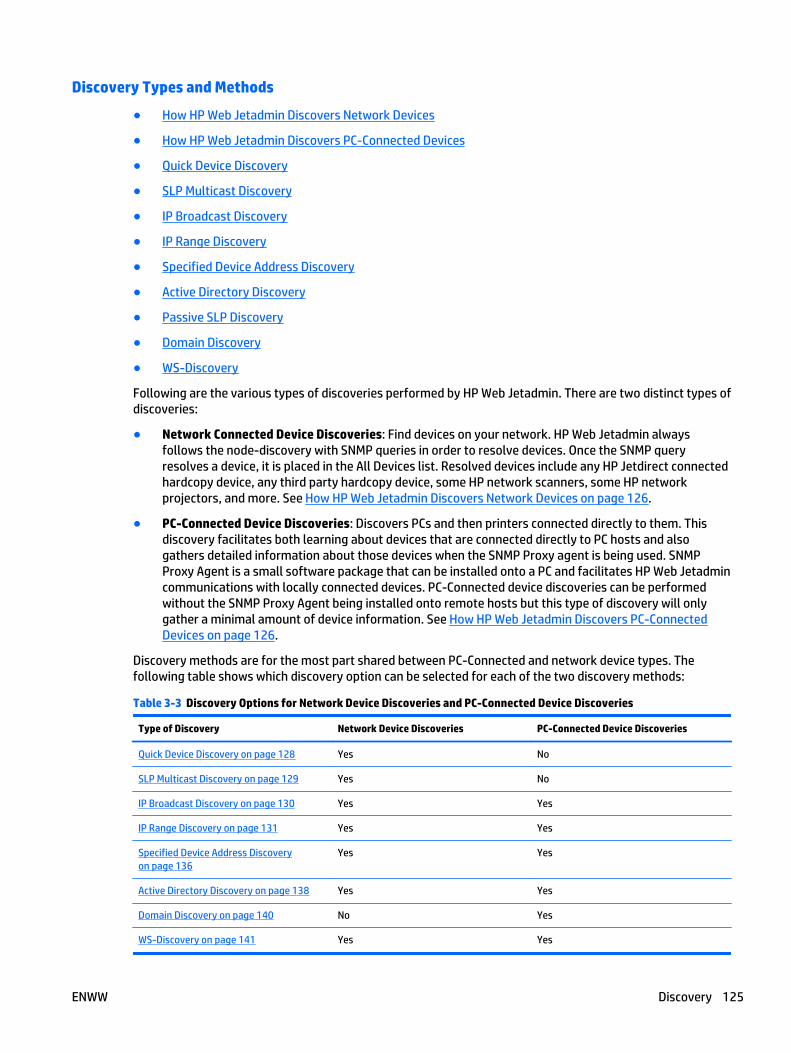
Discovery Types and Methods
● How HP Web Jetadmin Discovers Network Devices
● How HP Web Jetadmin Discovers PC-Connected Devices
● Quick Device Discovery
● SLP Multicast Discovery
● IP Broadcast Discovery
● IP Range Discovery
● Specified Device Address Discovery
● Active Directory Discovery
● Passive SLP Discovery
● Domain Discovery
● WS-Discovery
Following are the various types of discoveries performed by HP Web Jetadmin. There are two distinct types ofdiscoveries:
● Network Connected Device Discoveries: Find devices on your network. HP Web Jetadmin alwaysfollows the node-discovery with SNMP queries in order to resolve devices. Once the SNMP queryresolves a device, it is placed in the All Devices list. Resolved devices include any HP Jetdirect connectedhardcopy device, any third party hardcopy device, some HP network scanners, some HP networkprojectors, and more. See How HP Web Jetadmin Discovers Network Devices on page 126.
● PC-Connected Device Discoveries: Discovers PCs and then printers connected directly to them. Thisdiscovery facilitates both learning about devices that are connected directly to PC hosts and alsogathers detailed information about those devices when the SNMP Proxy agent is being used. SNMPProxy Agent is a small software package that can be installed onto a PC and facilitates HP Web Jetadmincommunications with locally connected devices. PC-Connected device discoveries can be performedwithout the SNMP Proxy Agent being installed onto remote hosts but this type of discovery will onlygather a minimal amount of device information. See How HP Web Jetadmin Discovers PC-ConnectedDevices on page 126.
Discovery methods are for the most part shared between PC-Connected and network device types. Thefollowing table shows which discovery option can be selected for each of the two discovery methods:
Table 3-3 Discovery Options for Network Device Discoveries and PC-Connected Device Discoveries
Type of Discovery Network Device Discoveries PC-Connected Device Discoveries
Quick Device Discovery on page 128 Yes No
SLP Multicast Discovery on page 129 Yes No
IP Broadcast Discovery on page 130 Yes Yes
IP Range Discovery on page 131 Yes Yes
Specified Device Address Discoveryon page 136
Yes Yes
Active Directory Discovery on page 138 Yes Yes
Domain Discovery on page 140 No Yes
WS-Discovery on page 141 Yes Yes
ENWW Discovery 125
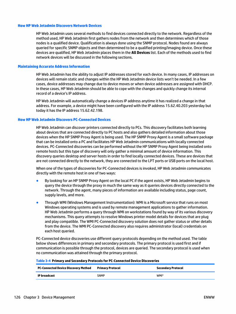
How HP Web Jetadmin Discovers Network Devices
HP Web Jetadmin uses several methods to find devices connected directly to the network. Regardless of themethod used, HP Web Jetadmin first gathers nodes from the network and then determines which of thosenodes is a qualified device. Qualification is always done using the SNMP protocol. Nodes found are alwaysqueried for specific SNMP objects and then determined to be a qualified printing/imaging device. Once thesedevices are qualified, HP Web Jetadmin places them in the All Devices list. Each of the methods used to findnetwork devices will be discussed in the following sections.
Maintaining Accurate Address Information
HP Web Jetadmin has the ability to adjust IP addresses stored for each device. In many cases, IP addresses ondevices will remain static and changes within the HP Web Jetadmin device lists won’t be needed. In a fewcases, device addresses may change due to device moves or when device addresses are assigned with DHCP.In these cases, HP Web Jetadmin should be able to cope with the changes and quickly change its internalrecord of a device’s IP address.
HP Web Jetadmin will automatically change a devices IP address anytime it has realized a change in thataddress. For example, a device might have been configured with the IP address 15.62.40.203 yesterday buttoday it has the IP address 15.62.42.198.
How HP Web Jetadmin Discovers PC-Connected Devices
HP Web Jetadmin can discover printers connected directly to PCs. This discovery facilitates both learningabout devices that are connected directly to PC hosts and also gathers detailed information about thosedevices when the HP SNMP Proxy Agent is being used. The HP SNMP Proxy Agent is a small software packagethat can be installed onto a PC and facilitates HP Web Jetadmin communications with locally connecteddevices. PC-Connected discoveries can be performed without the HP SNMP Proxy Agent being installed ontoremote hosts but this type of discovery will only gather a minimal amount of device information. Thisdiscovery queries desktop and server hosts in order to find locally connected devices. These are devices thatare not connected directly to the network, they are connected to the LPT ports or USB ports on the local host.
When one of the types of discoveries for PC-Connected devices is invoked, HP Web Jetadmin communicatesdirectly with the remote host in one of two ways:
● By looking for an HP SNMP Proxy Agent on the local PC if the agent exists, HP Web Jetadmin begins toquery the device through the proxy in much the same way as it queries devices directly connected to thenetwork. Through the agent, many pieces of information are available including status, page count,supply levels, and more.
● Through WMI (Windows Management Instrumentation): WMI is a Microsoft service that runs on mostWindows operating systems and is used by remote management applications to gather information.HP Web Jetadmin performs a query through WMI on workstations found by way of its various discoverymechanisms. This query attempts to resolve Windows printer model details for devices that are plugand play compatible. The WMI PC-Connected discovery solution does not gather status or other detailsfrom the device. The WMI PC-Connected discovery also requires administrator (local) credentials oneach host queried.
PC-Connected device discoveries use different query protocols depending on the method used. The tablebelow shows differences in primary and secondary protocols. The primary protocol is used first and ifcommunication is possible through the protocol, devices are queried. The secondary protocol is used whenno communication was attained through the primary protocol.
Table 3-4 Primary and Secondary Protocols for PC-Connected Device Discoveries
PC-Connected Device Discovery Method Primary Protocol Secondary Protocol
IP broadcast SNMP WMI*
126 Chapter 3 Device Management ENWW
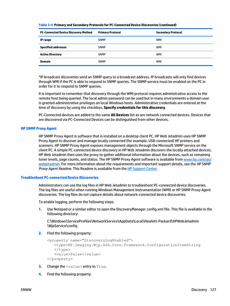
Table 3-4 Primary and Secondary Protocols for PC-Connected Device Discoveries (continued)
PC-Connected Device Discovery Method Primary Protocol Secondary Protocol
IP range SNMP WMI
Specified addresses SNMP WMI
Active Directory SNMP WMI
Domain SNMP WMI
*IP broadcast discoveries send an SNMP query to a broadcast address. IP broadcasts will only find devicesthrough WMI if the PC is able to respond to SNMP queries. The SNMP service must be enabled on the PC inorder for it to respond to SNMP queries.
It is important to remember that discovery through the WMI protocol requires administrative access to theremote host being queried. The local admin password can be used but in many environments a domain useris granted administrative privileges on local Windows hosts. Administrative credentials are entered at thetime of discovery by using the checkbox, Specify credentials for this discovery.
PC-Connected devices are added to the same All Devices list as are network connected devices. Devices thatare discovered via PC-Connected Devices can be distinguished from other devices.
HP SNMP Proxy Agent
HP SNMP Proxy Agent is software that is installed on a desktop client PC. HP Web Jetadmin uses HP SNMPProxy Agent to discover and manage locally connected (for example, USB-connected) HP printers andscanners. HP SNMP Proxy Agent exposes management objects through the Microsoft SNMP service on theclient PC. A simple PC-connected device discovery in HP Web Jetadmin discovers the locally attached devices.HP Web Jetadmin then uses the proxy to gather additional information about the devices, such as remainingtoner levels, page counts, and status. The HP SNMP Proxy Agent software is available from www.hp.com/go/webjetadmin. For more information about the requirements and important support details, see the HP SNMPProxy Agent Readme. This Readme is available from the HP Support Center.
Troubleshoot PC-connected Device Discoveries
Administrators can use the log files in HP Web Jetadmin to troubleshoot PC-connected device discoveries.The log files are useful when running Windows Management Instrumentation (WMI) or HP SNMP Proxy Agentdiscoveries. The log files do not capture details about network-connected device discoveries.
To enable logging, perform the following steps:
1. Use Notepad or a similar editor to open the DiscoveryManager.config.xml file. This file is available in thefollowing directory:
C:\Windows\ServiceProfiles\NetworkService\AppData\Local\Hewlett-Packard\HPWebJetadmin\WjaService\config
2. Find the following property:
<property name="DiscoveryLogEnabled”> <type>HP.Imaging.Wjp.Sdk.Core.Framework.ConfigurationItemString </type> <value>False</value></property>
3. Change the <value> entry to True.
4. Find the following property:
ENWW Discovery 127

<property name="NumDiscoveryLogs"> <type>HP.Imaging.Wjp.Sdk.Core.Framework.ConfigurationItemString </type> <value>2</value></property>
This property is useful when PC-connected device discoveries are performed over a long period of time.The default setting causes HP Web Jetadmin to overwrite a second log file for each new discovery.
5. To increase the number of log files that HP Web Jetadmin creates, change the <value> entry to therequired number of log files.
6. Close and save the DiscoveryManager.config.xml file.
7. Restart the HP Web Jetadmin service (HPWJA Service). For instructions, see Restart theHP Web Jetadmin Service Manually on page 21.
CAUTION: Be careful when restarting the HP Web Jetadmin service. Conflicts with existing operations,such as firmware upgrades, alerts, and data collection, might occur.
Each time HP Web Jetadmin contacts an address to determine if a PC-connected device is present,HP Web Jetadmin adds an entry to the log files in the following directory:
C:\Windows\ServiceProfiles\NetworkService\AppData\Local\Hewlett-Packard\HPWebJetadmin\WjaService\config\FileStore\Discovery\Specified
The following are examples of log entries:
● An SNMP error occurred when trying to contact remote server
An SNMP-related error occurred.
● An SNMP Credentials error has occurred
SNMP credentials are required for the device.
● An SNMP Timeout error has occurred
SNMP did not respond within the specified HP Web Jetadmin timeout settings. For more informationabout the SNMP timeout settings, see Configure the SNMP Settings on page 39.
● The remote server machine does not exist or is unavailable
The remote host does not qualify as a PC-connected host.
● A Timeout occurred trying to contact Remote Host
A timeout occurred while trying to start a WMI session with the host.
● The Remote host could not be contacted
A WMI session could not be started.
● Access is denied
The remote host denied access to a WMI session.
Quick Device Discovery
If you know the IP address or hostname of a network-connected device, you can use the Quick DeviceDiscovery feature to find the device instead of running a full network discovery. To use the IP hostname forthe Quick Device Discovery feature, DNS lookups must be enabled. For instructions on enabling DNS lookups,see Configure the DNS Settings on page 40.
128 Chapter 3 Device Management ENWW

You can only use the Quick Device Discovery feature to find PC-connected devices if the devices are already inthe HP Web Jetadmin database. To find a PC-connected device that is not in the database, you must run adevice discovery and use the PC connected devices option. For more information about PC-connected devicediscoveries, see How HP Web Jetadmin Discovers PC-Connected Devices on page 126.
To find a network-connected device, the Quick Device Discovery feature searches the device addresses in theHP Web Jetadmin database. If the device address is in the database, HP Web Jetadmin highlights the device inthe All Devices list. If the device address is not in the database, HP Web Jetadmin performs a network queryonly for network-connected devices. If the device address is found on the network, HP Web Jetadmin addsthe device to the database and highlights the device in the All Devices list.
The Quick Device Discovery feature does not search the device lists. For instructions on searching the visiblecolumns in device lists, see Search Device Lists on page 101.
Perform Quick Device Discoveries
1. In the Device Management navigation pane, enter the IP address or hostname for the device in theQuick Device Discovery box, and then click the Go button.
2. If the device is not found, perform the following steps:
a. Click the Credentials may be required to locate the device link.
b. On the Enter Credentials window, select the Use checkbox, enter the SNMPv1 Get CommunityName for the device, and then click the OK button.
c. If the device is found, continue with step 3.
-or-
If the device is not found, click the Cancel button. Verify that the device is connected to thenetwork, verify the device address and credentials, and then repeat the Quick Device Discovery.
3. On the Quick Device Discovery window, click the OK button.
SLP Multicast Discovery
● Details About Running an SLP Multicast Discovery
(For network device discoveries only.)
A discovery using SLP multicast requires minimal settings to launch. SLP (service location protocol) is used tocast a query onto the network for the purpose of finding HP Jetdirect devices. After initial device response,SNMP follow-up queries are performed to learn more about devices and add them to the All Device list inHP Web Jetadmin. This discovery mechanism finds HP Jetdirect devices on both local and remote subnets.
Characteristics of an SLP Multicast discovery for network devices include:
● Multicast packets are sent to the HP Jetdirect-specific multicast address: 224.0.1.60.
● Packets contain a router hop-counter (IP time to live attribute) that can be set from withinHP Web Jetadmin (default 4 hops).
● Packets expire when router hop-counter reaches zero.
● The discovery mechanism is fast.
● The discovery presents low network traffic.
● HP Jetdirect firmware must be at least x.06.00 or greater.
● Only HP Jetdirect-connected printers will be discovered.
The reach of SLP multicast discovery will depend upon the:
ENWW Discovery 129
● Setting for Routers to cross (hops) (a configuration option for Discovery; see Configure the GeneralSettings for Device Discoveries on page 56).
● Configuration of the network routers; if the router is configured to pass multicast requests on to othersections of your network, then a discovery could potentially discover devices on your entire network.
The other option to control the reach of the discoveries is to configure the multicast request to span a certainnumber of routers (Configure the General Settings for Device Discoveries on page 56). Spanning routers willrequire the routers to be configured to allow multicast request to be forwarded.
The discovery could also be affected by the configuration of your local firewall (Discovering Devices withHP Web Jetadmin through Firewalls on page 124).
If the router is configured to pass multicast requests on to other sections of the network, and Discovery isconfigured to cross multiple routers, then a discovery could potentially discover devices across multiplesubnets and perhaps your entire network.
Details About Running an SLP Multicast Discovery
(For network device discoveries only.)
If one of the discovery methods you choose is SLP multicast (while creating templates (Create a DiscoveryTemplate on page 154), editing templates (Edit a Discovery Template on page 156), or scheduling (Schedulea Discovery on page 151)), then the Choose SLP multicast settings page is displayed. On this page, selectthe number of routers to cross (or hops) for the discovery. Increasing the number of hops might increase theamount of time for the discovery to complete; plus, it generates more network traffic than a discovery withfewer routers to cross.
HP Web Jetadmin does not add devices that cannot be resolved and managed via SNMP, which might be dueto insufficient credentials, to the device list. HP Web Jetadmin enforces device manageability through SNMPbefore adding devices to the device list.
IP Broadcast Discovery
● IP Broadcast Discoveries for Network Devices
● IP Broadcast Discoveries for PC-Connected Devices
● Details About Running an IP Broadcast Discovery
IP Broadcast discoveries send SNMP query packets (in the form of IP broadcasts) to one or more IPnetwork(s). These are used in both PC-Connected and network device discoveries.
IP Broadcast Discoveries for Network Devices
An IP Broadcast discovery enables you to find devices or HP Web Jetadmin installations when IP broadcastaddressees are known. IP broadcast discoveries send SNMP query packets (in the form of IP broadcasts) toone or more IP network(s). One network-specific broadcast address exists for each IP subnet on an IPintranet. IP subnets are determined by the IP network number and the IP subnet mask. IP calculators,available free on the Internet, are a great way to determine IP broadcast addresses. An all 1s IP broadcast canalso be used to query the entire intranet. Broadcasting is typically blocked by routers due to traffic spikeconcerns.
Characteristics of IP broadcast discoveries for network devices include:
● Sends SNMP queries over one or more IP broadcasts.
● Listens for replies and then qualifies network connected devices.
● Default broadcast is the Global Broadcast Address (255.255.255.255).
● Can use one or more known IP broadcast addresses with optional address descriptions.
130 Chapter 3 Device Management ENWW
● Limited checking is performed to determine if the broadcast address is valid.
● Fast and thorough, especially on a local segment.
● Most modern networks block broadcast traffic.
IP Broadcast Discoveries for PC-Connected Devices
IP broadcast discoveries for PC-Connected devices send an SNMP query to the IP broadcast address specified.An all 1s broadcast is the default. Systems with the SNMP Proxy Agent first answer with the operatingsystem. HP Web Jetadmin follows up with queries to both host and to printer specific objects. IP Broadcastdiscovery does not attempt WMI queries when no SNMP proxy agent exists.
Characteristics of IP broadcast discoveries for PC-Connected devices include:
● Settings are the same as network device.
● SNMP queries are attempted on discovered nodes.
● If no SNMP Proxy Agent response, WMI queries are performed when credentials exist in settings.
NOTE: Legacy editions of Microsoft Windows Server that have HP SNMP Proxy Agent or HP WS Pro ProxyAgent do not always respond to IP broadcasts from the HP Web Jetadmin server. HP recommends that youuse alternate discovery methods to find PC-connected devices on legacy editions of Microsoft WindowsServer.
Details About Running an IP Broadcast Discovery
1. In the left navigation pane, click Discovery and then click Discover devices on my network (in theDiscovery - Current Tasks task module). The Device Discovery wizard is started with the Specifydiscovery options page displayed.
2. Select Specify settings and then select IP broadcast. Click Next. The Select IP broadcast address pageis displayed.
3. You can:
● Select a broadcast address.
● Add: Add a broadcast. Type the address in Address and type a description (if desired) inDescription. Then click Add.
● Show favorites only: View only the broadcast addresses you have added by clicking Showfavorites only (at the bottom of the page).
● Remove: Remove addresses from the list by highlighting the address and clicking Remove.
● Customize: Add or remove addresses to favorites by clicking Customize. Then select an addressand click Add Favorite or Remove Favorite. When done, click OK (Customizing IP Ranges forDiscoveries on page 135).
4. Click Next.
IP Range Discovery
● Setting Realistic Ranges
● Import and Export Features of IP Range Files
● IP Range Discoveries for Network Devices
● Customizing IP Ranges for Discoveries
● IP Range Discoveries for PC-Connected Devices
ENWW Discovery 131
● Details About Running an IP Range Discovery
In contrast to running a broadcast discovery (where all devices or HP Web Jetadmin installations in thesubnet are queried), you can choose to discover a specified IP range or a number of IP ranges. This reducesnetwork traffic and eliminates the possibility of having unwanted devices. HP Web Jetadmin installationsshow up in the database. IP Range discovery searches for devices or HP Web Jetadmin installations within arange of IP addresses. This type of discovery is accurate and thorough but can be slow for large ranges.
IP Range Discovery is effective when the administrator has knowledge of IP segments. Administrators use IPRange Discovery settings to map IP segments or groups of IP segments into HP Web Jetadmin discovery. Thismethod efficiently sweeps selected portions of the network or WAN. IP Range address pairs consist ofbeginning and ending IP addresses. IP Range discoveries first ping specific IP addresses as defined by rangeaddress pairs. If the device responds, HP Web Jetadmin follows with SNMP queries. Multiple ranges can bespecified in IP Range discoveries. HP Web Jetadmin pings in bursts of 30 queries to the first set of addressesfrom the first range and then waits one second before sending the next burst of 30 queries.
Setting Realistic Ranges
● Setting Ranges Based on Subnets or Contiguous Subnets
Most networks are divided up into subnets, which can be used to describe a network IP addressing schemeand are sometimes referred to as IP maps. A subnet within a large network can be described with a networknumber and a subnet mask. This is an example of one subnet with an IP range of 15.5.188.1 through15.5.191.254:
● Network number example: 15.5.188.0
● Subnet mask example: 255.255.252.0
There are 1,022 possible addresses on this subnet. It may take HP Web Jetadmin only about 10 minutes todiscover devices on this network depending on the network, the number of devices on that network, and thehost on which HP Web Jetadmin is installed.
NOTE: IP address calculators are an easy way to analyze IP networks. Many free versions of IP calculatorsexist and can be obtained on the Internet.
IP Range discovery can perform to expectations when the range data has been correctly developed. It is easyto configure ranges that are larger than needed and actually cause the discovery to take a long time andperhaps even yield little in the way of devices. For example, a class A range could easily be developed for theHP intranet but would literally take weeks to complete. On most large networks, the majority of the IPaddresses won’t answer the HP Web Jetadmin query and will cause timeouts to occur; these translate intovery long discovery times.
If you specify an IP range that is very large, your network might crash if that IP range is for a class A or class Bnetwork (when the first two octets of the IP range are not the same). HP Web Jetadmin will display a warningmessage stating that a large range might cause a large amount of network traffic; you can choose tocontinue or change the range.
You can choose to specify a large subnet range using the larger subnet address feature (Tools > Options >Shared > Discovery > Methods > IP Range > General). Large networks are considered any network biggerthan a Class B network, which has up to 65,000 nodes.
Setting Ranges Based on Subnets or Contiguous Subnets
Since large IP ranges can cause HP Web Jetadmin discovery to take long periods of time to complete, it can beuseful to use subnet ranges rather than the entire network for a discovery. These subnets, when put togetherinto one list, represent an IP map. This type of a map can be obtained from an IT or Network Infrastructureteam. It is also a good idea to work with these teams to discuss plans for implementing HP Web Jetadmindiscoveries.
132 Chapter 3 Device Management ENWW
NOTE: Hewlett-Packard strongly recommends that you discuss HP Web Jetadmin discoveries with yourinformation technology or network administration team.
Here is an example of IP range planning. Assume we have 27 subnets on our hypothetical network. All ofthese subnets use the same subnet mask of 255.255.255.0. Here are the network numbers that representour 27 subnets:
15.0.1.0, 15.0.2.0, 15.0.3.0, 15.0.4.0, 15.0.5.0, 15.0.30.0, 15.0.31.0, 15.0.32.0, 15.0.33.0, 15.0.34.0,15.0.35.0, 15.0.36.0, 15.0.37.0, 15.0.38.0, 15.0.39.0, 15.0.55.0, 15.0.64.0, 15.0.65.0, 15.0.66.0, 15.0.67.0,15.0.68.0, 15.0.69.0, 15.0.70.0, 15.0.71.0, 15.0.72.0, 15.0.73.0, 15.0.74.0
From this information, we can formulate the following IP address ranges and import them intoHP Web Jetadmin:
● 15.0.1.1-15.0.1.254
● 15.0.2.1-15.0.2.254
● 15.0.3.1-15.0.3.254
● 15.0.4.1-15.0.4.254
● 15.0.5.1-15.0.5.254
● 15.0.30.1-15.0.30.254
● 15.0.31.1-15.0.31.254
● 15.0.32.1-15.0.32.254
● 15.0.33.1-15.0.33.254
● 15.0.34.1-15.0.34.254
● 15.0.35.1-15.0.35.254
● 15.0.36.1-15.0.36.254
● 15.0.37.1-15.0.37.254
● 15.0.38.1-15.0.38.254
● 15.0.39.1-15.0.39.254
● 15.0.55.1-15.0.55.254
● 15.0.64.1-15.0.64.254
● 15.0.65.1-15.0.65.254
● 15.0.66.1-15.0.66.254
● 15.0.67.1-15.0.67.254
● 15.0.68.1-15.0.68.254
● 15.0.69.1-15.0.69.254
● 15.0.70.1-15.0.70.254
● 15.0.71.1-15.0.71.254
● 15.0.72.1-15.0.72.254
● 15.0.73.1-15.0.73.254
● 15.0.74.1-15.0.74.254
ENWW Discovery 133
We can take the formulation one step further and simplify things. Some of the IP ranges are contiguous.These contiguously-addressed subnets are one after the other, in order, making it easy to combine them. Thefinal result would look like this:
● 15.0.1.1-15.0.5.254
● 15.0.30.1-15.0.39.254
● 15.0.55.1-15.0.55.254
● 15.0.64.1-15.0.74.254
This has reduced the number of IP ranges from 27 to 4. We can build this into a form that is easily importedinto HP Web Jetadmin and also reflects descriptions. Here is an example of data that can be imported via atext file:
● 15.0.1.1-15.0.5.254 = subnet range for western area
● 15.0.30.1-15.0.39.254 = subnet range for central area
● 15.0.55.1-15.0.55.254 = subnet range for branch office
● 15.0.64.1-15.0.74.254 = subnet range for eastern area
Consolidating ranges makes dealing with large quantities of data simpler but may not help when descriptionsare needed for the purpose of cataloging ranges.
Import and Export Features of IP Range Files
IP range data can be developed in other tools and imported through text files. In fact, HP Web Jetadmin canexport IP range data to text files. This makes it easier to deal with large numbers of IP ranges, manipulatecomplex data and archive data for use in multiple instances. Tile format for IP Range import and export fileformat can be broken down as follows:
● 1 range per line
● Each IP address is separated by a hyphen character (-)
● Comment or description strings can be appended to the IP range by using an equal character (=)
Here is an example of 1 IP range with a comment: xxx.xxx.xxx.xxx-xxx.xxx.xxx.xxx=descriptive text string(where xxx represents an octet in the IP address).
There is no known limit to the number of IP ranges manageable within HP Web Jetadmin software. IP rangesare also used by other features like PC-Connected printer discovery and HP Web Jetadmin Installationsdiscovery. All IP ranges entered into HP Web Jetadmin can also be managed globally from within Tools >Options > Shared > Discovery > Methods > IP Range > IP Ranges.
IP Range Discoveries for Network Devices
IP Range discoveries for network devices or HP Web Jetadmin installations first send an SNMP query to alladdresses within the range. When nodes are discovered, HP Web Jetadmin performs queries to determinequalified devices. These qualified devices, when found, are added to the device lists.
Characteristics of IP range discoveries for network devices or HP Web Jetadmin installations include:
● IP ranges are simply two addresses that represent range begin and end points.
● Multiple ranges can be specified in an IP Range discovery.
● IP range data can be manually added through the user interface.
● IP ranges can be imported to HP Web Jetadmin from text files.
134 Chapter 3 Device Management ENWW
● Multiple IP ranges can be added and with optional, descriptive tags.
● HP Web Jetadmin sends 1 query to each address represented by the range.
● HP Web Jetadmin pings the device ranges in bursts of 30.
● HP Web Jetadmin has features to calculate IP ranges based on:
◦ Local client host
◦ HP Web Jetadmin server host
◦ Device
● HP Web Jetadmin IP Range discoveries have proven to be effective, accurate and thorough.
● HP Web Jetadmin IP Range discoveries can be very slow if not configured properly.
● HP Web Jetadmin IP Range discoveries can draw security attention due to their scanning action.
Customizing IP Ranges for Discoveries
To customize the IP ranges for discoveries, perform the following steps:
1. In the Device Management navigation pane, right-click Discovery, and then select Discover devices.The Device Discovery wizard starts.
2. On the Specify discovery options page, select the IP Range option, and then click Next.
3. On the Select IP ranges page, click Customize.
4. To add an address to the favorites list, select the address, and then click Add Favorite.
5. To delete an address from the favorites list, select the address, and then click Remove Favorite.
6. Click OK, and then continue with the Device Discovery wizard.
IP Range Discoveries for PC-Connected Devices
IP Range discoveries for PC-Connected devices first send an SNMP query to all addresses within the range. IfSNMP communication is possible on a device, the discovery attempts to find a locally connected printer. If noSNMP communication is possible and if the user provided administrative credentials, the discovery willattempt to find a locally connected printer on the device.
Characteristics of IP range discoveries for PC-Connected devices include:
● IP Range scanning is same as network connected.
● Nodes representing hosts are detected.
● SNMP queries are attempted on discovered nodes.
● If no SNMP Proxy Agent response, WMI queries are performed when credentials exist in settings.
Details About Running an IP Range Discovery
The Select IP ranges page is displayed when you choose IP range as the discovery method while:
● Creating discovery templates (Create a Discovery Template on page 154)
● Editing discovery templates (Edit a Discovery Template on page 156)
● Scheduling a discovery (Schedule a Discovery on page 151)
● Running a Web Jetadmin discovery (Find HP Web Jetadmin Installations on page 281)
ENWW Discovery 135

On the Select IP ranges page, you can select the IP address ranges displayed or you can edit the ranges.
1. Choose the action to take:
● Select an IP range.
● Add: Add an IP range by clicking Add. Type the range in First address and Last address; then typea description (if desired) in Description. Click Add.
To calculate a range, click Calculate range. The Calculate IP Range page is displayed:
◦ Subnet from my computer: Automatically use IP address ranges currently found on the localsubnet of your computer. You can add a description in Description if desired.
◦ Subnet from WJA server: Automatically use IP address ranges currently found on the subnetof the HP Web Jetadmin server. You can add a description in Description if desired.
◦ Subnet from network address: Type a known IP address and subnet mask. You can add adescription in Description if desired.
● Edit: Make changes to IP ranges by clicking Edit. Follow the steps in the bullet above for “Add”.
● Delete: Remove addresses from the list by highlighting the address and clicking Delete.
● Import: If desired, import a range list by clicking Import and then browse for the range list.
● Export: If desired, export a range list by clicking Export and then browse for location you want tostore the range list.
● Show favorites only: View only the IP ranges you have added by clicking Show favorites only (atthe bottom of the page).
● Customize: Add or remove addresses to favorites by clicking Customize. Then select an addressand click Add Favorite or Remove Favorite. When done, click OK.
2. Click OK.
Specified Device Address Discovery
● Specified Device Address Discoveries for Network Devices
● Specified Device Address Discoveries for PC-Connected Devices
● Details About Running a Specified Device Addresses Discovery
Sometimes there is enough information about your device fleet that enables building a base of deviceaddresses. These addresses can be added to HP Web Jetadmin through the Specified Address option (seeManage the Address Lists for Specified Address Discoveries on page 42).
Specified Device Address discoveries use an explicit list of device addresses. These addresses can be IPhostnames or IP addresses. IP hostnames can have fully qualified domain information appended. Addressinformation can be both imported from and exported to text files. Specified Device Address discovery workssimilarly to IP Range discovery; HP Web Jetadmin simply moves down a list of addresses, performing queriesand adding qualified devices to the all devices list.
Here is an example of a small specified address base:
● 15.5.2.1
● 15.5.62.4
● 15.5.8.3
● 15.5.8.7
136 Chapter 3 Device Management ENWW

● BP005a.yourco.com
● BP065
● BP076.yourco.com
NOTE: For PC-Connected device discoveries, HP Web Jetadmin follows SNMP queries with WMI querieswhen no SNMP Proxy Agent has been detected on the remote host.
Specified Device Address Discoveries for Network Devices
Network device discovery queries each address in the list specified. Devices qualified through these queriesare added to the All Devices list.
Characteristics of Specified Device Address discoveries for network devices include:
● Specified device address discoveries find devices based on user supplied addresses.
● IP address or hostnames are valid address forms.
● HP Web Jetadmin initially qualifies the device by using an SNMP query.
● Follow-up queries through SNMP qualify the device and place it into the All Devices list if appropriate.
● This discovery is very fast and only hits the addresses specified by the user.
● This discovery is only as accurate as the address base specified by the user.
● Addresses can be entered into HP Web Jetadmin one by one or they can be imported from text file.
● In HP Web Jetadmin, addresses can be exported to text file.
Specified Device Address Discoveries for PC-Connected Devices
Specified Address discoveries for PC-Connected devices first send an SNMP query to all addresses within thelist of addresses. If SNMP communication is possible on a device, the discovery attempts to find a locallyconnected printer. If no SNMP communication is possible and if the user provided administrative credentials,the discovery will attempt to find a locally connected printer on the device using WMI protocol.
Characteristics of Specified Device Address discoveries for PC-Connected devices include:
● Specified address scan is the same as network connected.
● Nodes representing hosts are detected.
● SNMP queries are attempted on discovered nodes.
● If no SNMP Proxy Agent response, WMI queries are performed when credentials exist in settings.
Details About Running a Specified Device Addresses Discovery
If one of the discovery methods you choose is Specified address (while creating templates (Create aDiscovery Template on page 154), editing templates (Edit a Discovery Template on page 156), or scheduling(Schedule a Discovery on page 151)), then the Select addresses page is displayed. On this page, you canselect the IP address ranges displayed or you can edit the addresses:
1. In the left navigation pane, click Discovery and then click Discover devices on my network (in theDiscovery - Current Tasks task module). The Device Discovery wizard is started with the Specifydiscovery options page displayed.
2. Select Specify settings and then select Specified addresses. Click Next. The Select addresses page isdisplayed.
3. Click Edit Addresses. The Specified Addresses page is displayed.
ENWW Discovery 137

4. Type the network address in Network address and click Add Address; the address is displayed below inthe box. Repeat this until you have entered all network addresses.
5. Check Show For Me next to each IP address you want to include on the Select IP ranges page (theprevious page).
6. If desired, remove any ranges by highlighting it and clicking Remove Address.
7. If desired, import a range list by clicking Import Addresses and then browse for the range list.
8. If desired, export a range list by clicking Export Addresses and then browse for location you want tostore the range list.
9. Click OK and then click Next. The Confirm page is displayed.
10. Click Start. The Results page is displayed. Click Done.
Active Directory Discovery
● Active Directory Discoveries for Network Devices
● Active Directory Discoveries for PC-Connected Devices
● Details About Running an Active Directory Discovery
Active Directory Discovery requires your knowledge about the Active Directory domain. HP Web Jetadminprovides a new discovery feature that queries Microsoft Active Directory using an Active Directory startingpoint such as domain, organization unit (OU), or other Active Directory containers. In the case of networkdevices, HP Web Jetadmin scans the Active Directory for published shared printers. In the case of PC-Connected device discovery, HP Web Jetadmin scans the active directory for Windows hosts. From theseinitially discovered lists of nodes, HP Web Jetadmin finds and qualifies devices and then adds them to the AllDevices list.
Active Directory Discoveries for Network Devices
Active Directory (AD) discovery requires your knowledge about the AD domain. Once the AD discovery isstarted, the LDAP protocol is used to query AD for published print shares. From print shares discovered, thePort Name field is checked for the default name forms which are all case-sensitive and include:
● IP_<ip-addr>
● mt:<ip-addr>
● ***ip_<ip-addr> (*** can be anything not containing "ip_")
● ip_<ip-addr>:*** (colon between the IP address and ***)
● ip_<ip-addr> *** (space between the IP address and ***)
● ip_<ip-addr>-*** (dash between the IP address and ***)
● ip_<ip-addr>_*** (underscore between the IP address and ***)
If any of these are found during the Node Discovery, the address is stored. Then, during the Node Resolve,the IP addresses are queried through SNMP to detect network connected printers. When network connecteddevices are discovered, they are added to the HP Web Jetadmin All Devices list. No special user credentialsare needed other than device based SNMP Get Community strings (normally not used). In fact,HP Web Jetadmin, running under the low privilege account, Network Service, takes the credentials of the userlogged in through the HP Web Jetadmin client and uses these to query the Active Directory.
You can choose to perform recursive queries meaning any sub-units below the specified path will besearched. The administrator can also perform discovery on multiple Active Directory locations. And, the
138 Chapter 3 Device Management ENWW
discovery can also be filtered on both location and description strings if these are published to the ActiveDirectory.
Characteristics of Active Directory discoveries for network devices include:
● You can activate Active Directory discovery by specifying AD location(s).
● You can optionally set location and/or description filtering to narrow Active Directory discovery.
● You can optionally specify Active Directory recursion searching to one or all levels below the specifiedAD location or locations.
● Active Directory discovery scans the directory for printer shares.
● IP addresses that are resolved from printer shares are queried using SNMP.
● Printers that are qualified are populated into the HP Web Jetadmin All Devices list.
● Discovery is fast.
● Discovery does not require any special privileges and relies on public Active Directory search.
● Discovery is accurate to the extent that network printers are shared and published through ActiveDirectory.
● Discovery relies on the fact that a default port name in the Active Directory share actually contains theprinter’s IP address.
Active Directory Discovery discovers published print queues in a network’s Active Directory. To find theIP address of the network device to which the print queue is attached, AD discovery parses the printqueue’s port. An IP address can only be detected from those print queues with ports with the defaultformat of IP_www.xxx.yyy.zzz.
Active Directory Discoveries for PC-Connected Devices
Active Directory discoveries for PC-Connected devices use the LDAP protocol to identify Windows hosts onthe network. Each host identified is queried using the WMI protocol. Administrative credentials are requiredfor this discovery. Once a connection is established through WMI, the host is queried for a locally connectedprinter.
Characteristics of Active Directory discoveries for PC-Connected devices include:
● Settings are identical to discoveries for network devices.
● Discoveries for PC-Connected devices scan Active Directory for Windows hosts.
● SNMP queries are attempted on discovered nodes.
● If no SNMP Proxy Agent response, WMI queries are performed when credentials exist in settings.
● Local administrator credentials are required to perform this discovery.
Details About Running an Active Directory Discovery
Start here if one of the discovery methods you choose is Active Directory (while creating templates (Create aDiscovery Template on page 154), editing templates (Edit a Discovery Template on page 156), or scheduling(Schedule a Discovery on page 151)), then the Specify Active Directory options page is displayed. On thispage, you can define options for Active Directory discoveries:
1. Type the path for the Active Directory location or browse to it. Then click Add; it will be displayed in thelist below.
2. Check next to any location you want included in the discovery.
ENWW Discovery 139
3. If desired, remove any ranges by highlighting it and clicking Remove.
4. Select the recursion level:
● Current level: discoveries check the container specified by the path and the contents of anycontainers in the path.
● All levels: discoveries check the container specified by the path plus the contents of all containersand sub-containers in the path.
5. Specify the print queue filter to use in Filter.
6. Click Next.
Passive SLP Discovery
(For network device discoveries only.)
When HP Jetdirect-connected devices are power-cycled, they propagate SLP (service location protocol)multicast packets. When HP Web Jetadmin detects an HP Jetdirect SLP multicast (recognized by the source124.0.1.60), it performs follow-up SNMP queries and adds the device to the All Devices list.
Characteristics of Passive SLP discoveries for network devices include:
● Passive SLP discovery is quiet; HP Web Jetadmin does not propagate traffic unless a previouslyundetected device announces itself.
● HP Web Jetadmin listens for UDP traffic on port 427.
● Devices, including new devices, are discovered as they are powered on.
● Router filtering may inhibit multicast packets.
● Can be disabled on HP Jetdirect print servers.
● Will only discover HP Jetdirect-connected print servers.
Domain Discovery
● Details About Running a Discovery Using Domains
(For PC-Connected device discoveries only.)
For Domain discoveries for PC-Connected devices, the domain is browsed to identify Windows hosts on thenetwork. Each host identified is queried using the SNMP or WMI protocol. Administrative credentials arerequired for WMI. For WMI, once a connection is established the host is queried for a locally connected printer.
Characteristics of domain discoveries for PC-Connected devices include:
● SNMP queries are attempted on discovered nodes.
● If no SNMP Proxy Agent response, WMI queries are performed when credentials exist in settings.
● Might be slow on large domains.
● Local administrator credentials are needed to perform this discovery.
Details About Running a Discovery Using Domains
Start here if one of the discovery methods you choose is Domain (while creating templates (Create aDiscovery Template on page 154), editing templates (Edit a Discovery Template on page 156), or scheduling(Schedule a Discovery on page 151)), then the Select domains page is displayed. On this page, you can selectthe domains to include in the discoveries:
140 Chapter 3 Device Management ENWW

1. Type the domain in Domain or browse for the domain. Then click Add. The domain is displayed in theDomain box below.
To remove any domains from the Domain box, highlight the domain and click Remove.
2. Click Next.
WS-Discovery
● Details About Running a WS-Discovery
A discovery that uses the Web Services protocol requires minimal settings to launch. HP Web Jetadmin usesthe Web Services protocol to query the network to find network-connected and PC-connected devices. Afteran initial device response, HP Web Jetadmin performs additional SNMP queries to learn more about thedevices and add them to the All Devices list. This discovery mechanism finds devices on both local andremote subnets.
Characteristics of a Web Services discovery for network devices include the following:
● Packets contain a router hop-counter (IP time to live attribute) that can be set from withinHP Web Jetadmin. The default is 4 hops.
● Packets expire when the router hop-counter reaches zero.
● The discovery mechanism is fast.
● The discovery presents low network traffic.
The reach of a Web Services discovery depends on the following:
● The setting for the Routers to cross (hops) configuration option for the discovery (see Configure theGeneral Settings for Device Discoveries on page 56).
● The configuration of the network routers. If the router is configured to pass Web Services requests on toother sections of the network, then a discovery might discover devices on the entire network.
You can also control the reach of discoveries by configuring the Web Services request to span a certainnumber of routers (see Configure the General Settings for Device Discoveries on page 56). The routers mustbe configured to allow the Web Services request to be forwarded.
The discovery can also be affected by the configuration of the local firewall (see Discovering Devices withHP Web Jetadmin through Firewalls on page 124).
If the router is configured to pass Web Services requests on to other sections of the network and thediscovery is configured to cross multiple routers, then the discovery might discover devices across multiplesubnets and perhaps the entire network.
Details About Running a WS-Discovery
If you choose the WS-Discovery method while creating templates (see Create a Discovery Templateon page 154), editing templates (see Edit a Discovery Template on page 156), or scheduling discoveries (seeSchedule a Discovery on page 151), then the Choose WS-Discovery settings page is displayed. On this page,select the number of routers to cross (or hops) for the discovery. Increasing the number of hops mightincrease the amount of time for the discovery to complete. In addition, the discovery generates morenetwork traffic than a discovery with fewer routers to cross.
Managing Third-Party Printers in HP Web Jetadmin
● Support
● Functionality Definitions
ENWW Discovery 141
● Troubleshooting
During device discoveries, HP Web Jetadmin uses SNMP queries to gather information from the device. IfHP Web Jetadmin concludes that the device is a peripheral such as a printer, plotter, or multifunction device,it displays the device in the list of discovered devices. For HP Web Jetadmin to conclude that a device is aperipheral, the device must be able to answer a set of industry-standard questions.
A Management Information Base (MIB) is a set of objects that defines the types of SNMP queries that can beasked of a device. For example, the Standard Printer MIB (RFC 1759) is a generic set of objects to which mostperipherals should be able to provide answers when queried. The Standard Printer MIB consists of objectsthat describe functionality and capabilities of the printer such as page counts and media types. Othercommon MIBs include MIB2 (RFC 1213) and the Host Resources MIB (RFC 1514). Device vendors also have aset of proprietary MIBs that contain information unique to their devices. HP Web Jetadmin must haveknowledge of MIB objects in device plug-ins before it can send queries to devices using those MIB objects.
Devices must be able to answer queries defined in the common industry-standard MIBs for HP Web Jetadminto discover the devices. Otherwise, there is not enough information about the device to warrant displaying itin the list of discovered devices. HP Web Jetadmin focuses on printer management, and it would beincreasingly difficult to distinguish devices as printers unless they can answer a standard set of questionssuch as those defined in the Standard Printer MIB.
After HP Web Jetadmin discovers a device, the level of support that can be provided depends on the depth ofqueries defined in the respective device plug-ins.
Support
Support in HP Web Jetadmin can be quite extensive if the device can answer industry-standard queries. Quitea bit of HP Web Jetadmin functionality can be supported through standard queries such as basic status,configuration, alerts, reporting, and page counting. HP Web Jetadmin attempts to support the followingfunctionality for third-party devices using standard queries for basic support.
Device Page — Status Tab
● Device and Information categories
◦ Picture of a generic device, possibly vendor specific
◦ Device Model, IP Hostname, IP Address, System Contact
● Status category
◦ Basic status (online/offline, toner low, toner out, media low, media out, paper jam, cover open,service requested)
◦ Front panel display
● Supply levels category
◦ Input tray remaining levels
◦ Supplies remaining levels
Device Page — Config tab
● Device category
◦ Contact Person
◦ Control Panel Language
142 Chapter 3 Device Management ENWW

◦ PJL Configuration
◦ Company Name
● Network
◦ System Name
◦ Proxy Server
Device Page — Alerts tab
● General alerts only, polling only of SNMP Alert table and status OIDs
Device Page — Troubleshoot tab
● Reset Device button
● Embedded Web Server button
Device Page — Supplies tab
● Input tray levels
● Supplies levels
Device Page — Capabilities
● Installed components such as input tray capacities, interpreter languages, duplexer, hard disk, totalmemory
Alerts
● Polling only, no traps
● Limited set of events
◦ Service (online, offline, error, disconnected)
◦ Supplies (paper out, toner low, toner out, other supplies low/out/replace)
◦ Media Path (paper jam, cover open, output full)
Reports
● Device Inventory
● Supply Utilization
Columns
● Serial Number
● Contact Person
● System Contact
● System Location
● System Name
● System Up Time
ENWW Discovery 143
Functionality Definitions
This section provides definitions for many of the supported features for third-party devices and the objectsused for obtaining the information. The feature is supported if the device can answer the industry-standardquery defined in these definitions.
● Alerts: Polling at a specified interval is used to provide alerts that support the following types of eventsbased on status queries that match certain conditions or prtAlerts table objects. Standard statusqueries can typically determine the following types of alert conditions:
◦ Cover Open
◦ Offline
◦ Paper Jam
◦ Printer Error
Certified devices can process traps for real-time alerts when events occur for most events under theGeneral category. Polling of remaining supplies levels to provide Supplies alerts at desired thresholds isalso available for certified devices.
● Bitmap and Icon: HP Web Jetadmin displays any predefined bitmaps and icons that were created in adevice plug-in. Certified devices have a unique picture that matches the device, while basic supportprovides one generic picture per third-party vendor.
● Capabilities: Capabilities such as installed languages, trays, and accessories are displayed on theCapabilities tab as supported by the device using objects such as prtInterpreterDescription andprtInputDescription.
● Configuration: The following items are provided at a minimum for configuration, assuming that thedevice supports the following objects:
◦ System Contact (sysContact)
◦ System Location (sysLocation)
◦ Control Panel Language (prtConsoleLocalization)
◦ Contact Person (prtGeneralServicePerson)
◦ System Name (sysName)
Certified devices can provide extended configuration items using vendor-specific objects.
● Control Panel Display: The current message on the printer front panel is displayed usingprtConsoleDisplayBufferText.
● Description: A description is displayed from the response to sysLocation.
● Engine Cycle Count: Engine Cycle Count is a value stored on the printer that represents a cumulativetotal of pages printed for the life of the printer. Engine Cycle Count is displayed if a printer supportsprtMarkerLifeCount. Page counts for mono, color, simplex duplex, fax, copy, and scan are onlyobtainable via proprietary queries and require advanced support such as qualified or certified.
● IP Hostname: The IP hostname is displayed if the operating system can resolve an IP address to ahostname from a name server such as DNS or WINS using a GetHostByAddr call. System Name, whichcan be the hostname if the NIC registers it with a name server, is displayed if the device answers thesysName MIB2 object.
● Model: The printer model name is displayed according to the response to hrDeviceDescr.
● Serial Number: The serial number is a unique manufacturing identifier for the device. The serial numberis a critical identifier item that HP Web Jetadmin uses to determine the uniqueness of a device along
144 Chapter 3 Device Management ENWW
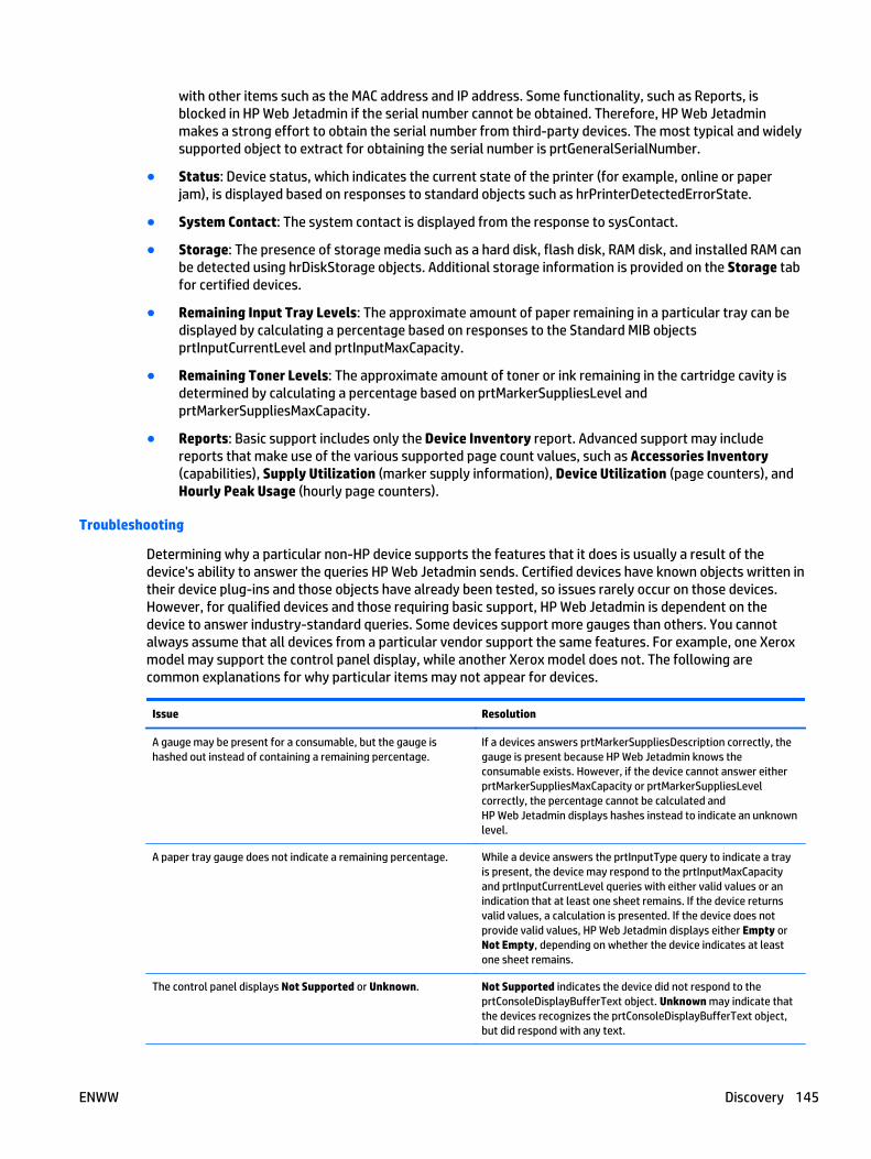
with other items such as the MAC address and IP address. Some functionality, such as Reports, isblocked in HP Web Jetadmin if the serial number cannot be obtained. Therefore, HP Web Jetadminmakes a strong effort to obtain the serial number from third-party devices. The most typical and widelysupported object to extract for obtaining the serial number is prtGeneralSerialNumber.
● Status: Device status, which indicates the current state of the printer (for example, online or paperjam), is displayed based on responses to standard objects such as hrPrinterDetectedErrorState.
● System Contact: The system contact is displayed from the response to sysContact.
● Storage: The presence of storage media such as a hard disk, flash disk, RAM disk, and installed RAM canbe detected using hrDiskStorage objects. Additional storage information is provided on the Storage tabfor certified devices.
● Remaining Input Tray Levels: The approximate amount of paper remaining in a particular tray can bedisplayed by calculating a percentage based on responses to the Standard MIB objectsprtInputCurrentLevel and prtInputMaxCapacity.
● Remaining Toner Levels: The approximate amount of toner or ink remaining in the cartridge cavity isdetermined by calculating a percentage based on prtMarkerSuppliesLevel andprtMarkerSuppliesMaxCapacity.
● Reports: Basic support includes only the Device Inventory report. Advanced support may includereports that make use of the various supported page count values, such as Accessories Inventory(capabilities), Supply Utilization (marker supply information), Device Utilization (page counters), andHourly Peak Usage (hourly page counters).
Troubleshooting
Determining why a particular non-HP device supports the features that it does is usually a result of thedevice's ability to answer the queries HP Web Jetadmin sends. Certified devices have known objects written intheir device plug-ins and those objects have already been tested, so issues rarely occur on those devices.However, for qualified devices and those requiring basic support, HP Web Jetadmin is dependent on thedevice to answer industry-standard queries. Some devices support more gauges than others. You cannotalways assume that all devices from a particular vendor support the same features. For example, one Xeroxmodel may support the control panel display, while another Xerox model does not. The following arecommon explanations for why particular items may not appear for devices.
Issue Resolution
A gauge may be present for a consumable, but the gauge ishashed out instead of containing a remaining percentage.
If a devices answers prtMarkerSuppliesDescription correctly, thegauge is present because HP Web Jetadmin knows theconsumable exists. However, if the device cannot answer eitherprtMarkerSuppliesMaxCapacity or prtMarkerSuppliesLevelcorrectly, the percentage cannot be calculated andHP Web Jetadmin displays hashes instead to indicate an unknownlevel.
A paper tray gauge does not indicate a remaining percentage. While a device answers the prtInputType query to indicate a trayis present, the device may respond to the prtInputMaxCapacityand prtInputCurrentLevel queries with either valid values or anindication that at least one sheet remains. If the device returnsvalid values, a calculation is presented. If the device does notprovide valid values, HP Web Jetadmin displays either Empty orNot Empty, depending on whether the device indicates at leastone sheet remains.
The control panel displays Not Supported or Unknown. Not Supported indicates the device did not respond to theprtConsoleDisplayBufferText object. Unknown may indicate thatthe devices recognizes the prtConsoleDisplayBufferText object,but did respond with any text.
ENWW Discovery 145

Issue Resolution
The model name for the device appears to be a much longername than the true name of the device.
HP Web Jetadmin relies on hrDeviceDescr to display the modelname. Properly truncated model names are generally provided inproprietary objects. HP Web Jetadmin does not know how totruncate a response to hrDeveiceDescr if it contains too manycharacters. For example, if a Lexmark printer responds withLexmark X652de 7932M8R LJ.MN.P092, HP Web Jetadmin doesnot know where to truncate the string.
No consumable gauges are present for items such as toner andfuser.
A device must answer prtMarkerSuppliesDescription correctly,otherwise HP Web Jetadmin does not know that the consumableexists and cannot display a gauge.
Task Modules for Discovery
● Discovery - Current Tasks and Common Tasks Task Modules
● Discovery - Summary Task Module
● Discovery - Active Discoveries Task Module
● Discovery - Scheduled Discoveries Task Module
● Discovery - Templates Task Module
● Discovery - Quick Monitor Task Module
The following task modules can be displayed or hidden in Discovery.
Discovery - Current Tasks and Common Tasks Task Modules
The Discovery - Current Tasks task module can be displayed on the Discovery page and includes thefollowing tasks:
● Discover Devices (the Device Discovery Wizard) on page 149
● Schedule a Discovery on page 151
● Create a Discovery Template on page 154
● Apply (or Run) a Discovery Template on page 155
● Edit a Discovery Template on page 156
● Delete a Discovery Template on page 157
● Copy Template Wizard on page 85
The Discovery - Current Tasks task module can be displayed in other areas of HP Web Jetadmin; in the otherareas it is called Discovery - Common Tasks.
Discovery - Summary Task Module
The Discovery - Summary task module gives you the date and time of the last discovery. You can:
● Discovery History on page 153.
● Discover Devices (the Device Discovery Wizard) on page 149.
Discovery - Active Discoveries Task Module
The Discovery - Active Discoveries task module shows you any discoveries currently running. You can:
146 Chapter 3 Device Management ENWW
● Stop a discovery by highlighting it and clicking Stop. To stop multiple tasks, use Ctrl-Enter orShift-Enter and then click Stop.
● View the progress of the discovery by highlighting it and clicking View.
Discovery - Scheduled Discoveries Task Module
The Discovery - Scheduled Discoveries task module shows you any discoveries that are scheduled to run butthat have not run yet. You can:
● Delete a Discovery Template on page 157
● Edit a Discovery Template on page 156
Discovery - Templates Task Module
The Discovery - Templates task module enables you to perform any action on a discovery template:
● Create a Discovery Template on page 154
● Apply (or Run) a Discovery Template on page 155
● Edit a Discovery Template on page 156
● View. The following is displayed:
◦ Discovery type: Network device discovery or PC-Connected device discovery.
◦ Credentials specified: Whether or not credentials were requested for devices.
◦ Use global credentials: Uses credentials established in Tools > Options > Shared > Credentials(does not require you to provide credentials).
◦ Discovery methods: A summary of the different methods used.
From this summary template page, you can:
◦ Edit (Edit a Discovery Template on page 156).
◦ Apply (Apply (or Run) a Discovery Template on page 155).
◦ Delete (Delete a Discovery Template on page 157).
● Delete a Discovery Template on page 157
● Copy Template Wizard on page 85
● View a Discovery Template on page 157
Discovery - Quick Monitor Task Module
The Discovery - Quick Monitor task module enables you to discover a specific device and monitor its statusall in one step. Enter the device’s IP address in Device and then click Go; or drag a device from any device listinto the quick monitor task module.
● Go: Type an IP address or hostname in Device and click Go; the device status and information isdisplayed.
● Clear: Removes all information from the Quick Monitor task module.
● Open: When activated in the Device Management view, brings the user to the All Devices list with thedevice specified in Quick Monitor task module selected within the All Devices list.
ENWW Discovery 147
Related Application Options for Discovery
● SNMPv3 Enabled Devices
● Network
Discovery settings refine the way HP Web Jetadmin performs a discovery in your own environment.Configuration options for Discovery include:
● Configure the General Settings for Device Discoveries on page 56 (Tools > Options > DeviceManagement > Device Discovery > General)
● IP Range (Tools > Options > Shared > Discovery > Methods > IP Range > General > Configure LargeSubnets for IP Range Discoveries on page 41)
● IP Range (Tools > Options > Shared > Discovery > Methods > IP Range > Manage the IP Ranges forDiscoveries on page 42)
SNMPv3 Enabled Devices
Devices that have SNMPv3 fully enabled can be discovered by HP Web Jetadmin. To discover these devices,enable Discover SNMP v3 devices in Tools > Options > Device Management > Device Discovery > General.
HP Web Jetadmin requires SNMPv3 credentials for these devices in order for them to be discovered. There aretwo ways HP Web Jetadmin can become aware of device SNMPv3 credentials:
● HP Web Jetadmin is used to enable SNMPv3 and also configure the SNMPv3 credentials onto thedevices. In this case, HP Web Jetadmin stores the credentials into its credential store and uses themwhenever device communication is required. HP Web Jetadmin also marks these devices as SNMPv3-enabled and remembers to use the credentials and SNMPv3 whenever communication is required.
● HP Web Jetadmin has had SNMPv3 credentials added to the Global credentials store and thesecredentials match those credential values on the devices. In this case, HP Web Jetadmin is being madeaware of credential values that work for devices that are SNMPv3-enabled. When one of these devicesis encountered, HP Web Jetadmin will try the credential values that are configured using the optionSNMPv3 Credentials in Tools > Options > Shared > Credentials. If the credential values work andHP Web Jetadmin is able to communicate with the devices, the credential values will be storedindividually for each device.
Devices that were discovered through SNMPv1 and have had SNMPv3 enabled through some other meanssuch as Embedded Web Server or another instance of HP Web Jetadmin will indicate a communication failurewhen HP Web Jetadmin attempts to re-establish communication. The Refresh Selection (Full) command canbe used on these devices to cause HP Web Jetadmin to reset them to SNMPv3-enabled devices.
NOTE: If SNMPv3 communication was established outside of HP Web Jetadmin, the global discovery settingfor Discover SNMPv3 Devices must be configured in Tools > Options > Device Management > Discovery >General. No new SNMPv3 devices will be added to the database unless this option is enabled.
Network
Related options that can be set in HP Web Jetadmin through Tools > Options > Shared > Network include:
● Configure the SNMP Settings on page 39:
148 Chapter 3 Device Management ENWW
◦ SNMPv1 timeout value: Specify how long HP Web Jetadmin waits for a reply from a network querythat is sent to SNMPv1 devices. The default is 500 ms.
◦ SNMPv3 timeout value: Specify how long HP Web Jetadmin waits for a reply from a network querythat is sent to SNMPv3 devices. The default is 1000 ms.
◦ SNMP retries: Specify how many times HP Web Jetadmin retries an SNMP communication withdevices after a timeout occurs. The default is 3.
● Configure the DNS Settings on page 40 (Enable DNS lookups): Forces HP Web Jetadmin to query nameservices for each device discovered. This setting is sometimes disabled in environments where DNSresponses are slow or are not functioning. (The default is on.)
● Manage the IP Ranges for Discoveries on page 42: Global store for IP Range settings used by networkdevice discovery, PC-Connected device discovery and HP Web Jetadmin application discovery.
● Shared Configuration Options for Credentials on page 45: In some cases, credentials like Manage theGlobal SNMPv1 Get Community Names on page 48 or Manage the Global SNMPv3 Credentialson page 49 are being used. Use Credentials to set well known device credentials. These will be triedduring discovery when devices don’t respond to queries that use default credentials.
Discover Devices (the Device Discovery Wizard)
● Discover Devices
● Steps to Discover Devices
● Other Ways to Discover Devices
Discover Devices launches the HP Web Jetadmin Device Discovery wizard. This wizard is used to launch orschedule any type of active discovery method. The wizard ends with a Results page that can be monitored orhidden.
Discover Devices
Node-discovery and node-resolve progress are both reported through a Results page, which is the last pagedisplayed as part of the Device Discovery wizard.
The Results page displays progress for the different portions of a discovery. This can make it easy todetermine which method is currently executing or whether node-discovery or node-resolve portions havebegun execution. Here is a list of items displayed on the Results page:
● Progress: Shows a throbber graphic and percentage complete, or it shows that the discovery iscomplete.
● Started by: Shows the user that initiated the discovery.
● Progress (estimated): Shows an overall estimated percentage.
● Current method: States the current method executing (IP Range, and so forth).
● Nodes found: Shows a count of nodes responding so far.
● Nodes resolved: Shows the number of nodes being resolved.
● Devices found (this discovery): Shows a count of nodes that are qualified devices (network or PC-Connected).
● New devices (this discovery): Shows a count of devices that are new since last discovery.
ENWW Discovery 149

Steps to Discover Devices
1. In the left navigation pane, click Discovery and then click Discover devices on my network (in theDiscovery - Current Tasks task module). The Device Discovery wizard is started with the Specifydiscovery options page displayed.
2. To use an existing discovery template, select the Use template option, and select the template fromthe drop-down list.
3. Select the type of discovery you want to perform (Network connected devices or PC connecteddevices).
NOTE: For more information about any of the types of discoveries, see Discovery Types and Methodson page 125.
NOTE: IP broadcast discoveries send an SNMP query to a broadcast address. IP broadcasts will onlyfind devices through WMI if the PC is able to respond to SNMP queries. The SNMP service must beenabled on the PC in order for it to respond to SNMP queries. For more information, see HowHP Web Jetadmin Discovers PC-Connected Devices on page 126.
4. Under Network connected devices or PC connected devices, select the discovery method you want touse (see Discovery Types and Methods on page 125). You must select at least one.
5. To run this discovery later, check Schedule discovery. To run this discovery now, leave this boxunchecked.
NOTE: If you schedule a task (for example, a discovery or a configuration or others) using acorresponding template, the task uses the settings defined in the template at the time the task starts.This makes it easy to redefine settings used in a regularly scheduled task without having to delete andcreate a scheduled task.
NOTE: All schedules use the date and time on the server where HP Web Jetadmin is installed. Theclient used to access HP Web Jetadmin might not be in the same time zone as the server where HP WebJetadmin is installed. You should be aware of the potential for time and date differences whenconfiguring schedules.
NOTE: Scheduled tasks are displayed in the Scheduled Tasks task module on the Device, Discovery,Configuration, Firmware, Reports, Storage, Solutions, and Application Management pages. You canalso display any task module on the Overview page.
6. Click Next.
7. The wizard displays a page with the settings for the discovery method you selected. Specify thesettings, and then click Next.
NOTE: If you selected more than one discovery method, the wizard displays a separate settings pagefor each discovery method.
8. If you want to specify credentials for this discovery, select the Specify credentials to use for thisdiscovery option. This is used if devices are configured for SNMPv3 or if non-standard SNMP GetCommunity Names are being used.
9. Click Next.
10. If you chose to schedule this discovery, the Specify schedule options page is displayed:
a. Enter the name of this schedule in Name.
b. Select the start date and time from the drop-down lists.
c. Select the recurrence for this schedule.
d. Click Next.
150 Chapter 3 Device Management ENWW
NOTE: For more information about scheduling discoveries, see Schedule a Discovery on page 151.
11. The Confirm page is displayed. If all of the settings are correct, click Start.
12. The Progress page is displayed showing you the Discovery’s progress. To hide the discovery click Hide;to stop the discovery click Stop.
13. When the discovery has completed (or if you click Stop during the discovery), the Results page isdisplayed:
● To view the discovered devices, check View all devices.
● To exit, click Done.
Other Ways to Discover Devices
1. In the left navigation pane, right-click on All Devices and select Discover devices.
2. Within any device list, right-click and select Discover.
Schedule a Discovery
● Example for Scheduling Discoveries
● Steps to Schedule a Discovery
● Other Ways to Schedule a Discovery
HP Web Jetadmin has a flexible discovery scheduler that allows the administrator to launch specificdiscoveries at the desired date and time. Multiple schedules can be created and maintained which enables theadministrator the flexibility of launching different discoveries in different time zones and with differentsettings. Both PC-Connected device discovery and network connected device discovery can be scheduled.Many discovery schedules can exist and be run as a one-time event or as recurring events.
NOTE: If you schedule a task (for example, a discovery or a configuration or others) using a correspondingtemplate, the task uses the settings defined in the template at the time the task starts. This makes it easy toredefine settings used in a regularly scheduled task without having to delete and create a scheduled task.
NOTE: All schedules use the date and time on the server where HP Web Jetadmin is installed. The clientused to access HP Web Jetadmin might not be in the same time zone as the server where HP Web Jetadmin isinstalled. You should be aware of the potential for time and date differences when configuring schedules.
NOTE: Scheduled tasks are displayed in the Scheduled Tasks task module on the Device, Discovery,Configuration, Firmware, Reports, Storage, Solutions, and Application Management pages. You can alsodisplay any task module on the Overview page.
Characteristics of scheduling discoveries include:
● Scheduled discoveries can contain different types of Discovery settings including different settingsvalues such as IP range, broadcast addresses, and so forth.
● Recurring schedules can be set up to be daily, weekly, monthly, and so forth.
● Specific weekdays can be chosen for recurring schedules.
● Settings within preexisting schedules can be altered without having to create new scheduled events.
● A Discovery - Scheduled Discoveries Task Module on page 147 exists to easily view, edit and deleteexisting schedules.
ENWW Discovery 151
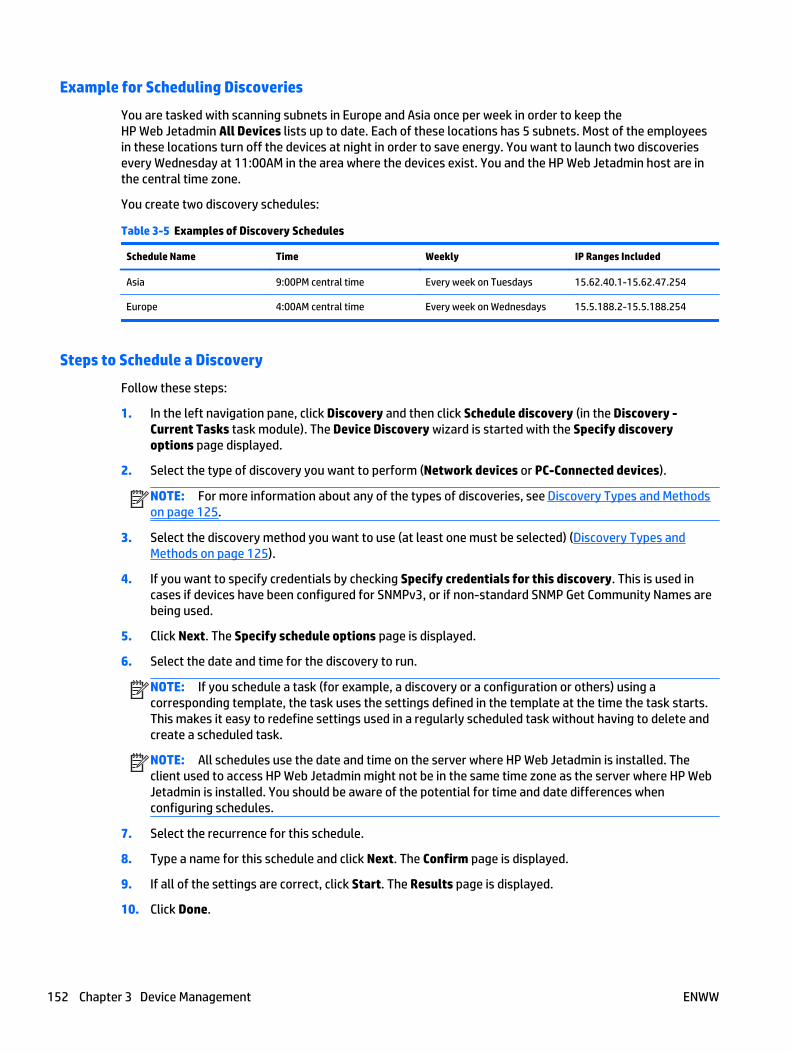
Example for Scheduling Discoveries
You are tasked with scanning subnets in Europe and Asia once per week in order to keep theHP Web Jetadmin All Devices lists up to date. Each of these locations has 5 subnets. Most of the employeesin these locations turn off the devices at night in order to save energy. You want to launch two discoveriesevery Wednesday at 11:00AM in the area where the devices exist. You and the HP Web Jetadmin host are inthe central time zone.
You create two discovery schedules:
Table 3-5 Examples of Discovery Schedules
Schedule Name Time Weekly IP Ranges Included
Asia 9:00PM central time Every week on Tuesdays 15.62.40.1-15.62.47.254
Europe 4:00AM central time Every week on Wednesdays 15.5.188.2-15.5.188.254
Steps to Schedule a Discovery
Follow these steps:
1. In the left navigation pane, click Discovery and then click Schedule discovery (in the Discovery -Current Tasks task module). The Device Discovery wizard is started with the Specify discoveryoptions page displayed.
2. Select the type of discovery you want to perform (Network devices or PC-Connected devices).
NOTE: For more information about any of the types of discoveries, see Discovery Types and Methodson page 125.
3. Select the discovery method you want to use (at least one must be selected) (Discovery Types andMethods on page 125).
4. If you want to specify credentials by checking Specify credentials for this discovery. This is used incases if devices have been configured for SNMPv3, or if non-standard SNMP Get Community Names arebeing used.
5. Click Next. The Specify schedule options page is displayed.
6. Select the date and time for the discovery to run.
NOTE: If you schedule a task (for example, a discovery or a configuration or others) using acorresponding template, the task uses the settings defined in the template at the time the task starts.This makes it easy to redefine settings used in a regularly scheduled task without having to delete andcreate a scheduled task.
NOTE: All schedules use the date and time on the server where HP Web Jetadmin is installed. Theclient used to access HP Web Jetadmin might not be in the same time zone as the server where HP WebJetadmin is installed. You should be aware of the potential for time and date differences whenconfiguring schedules.
7. Select the recurrence for this schedule.
8. Type a name for this schedule and click Next. The Confirm page is displayed.
9. If all of the settings are correct, click Start. The Results page is displayed.
10. Click Done.
152 Chapter 3 Device Management ENWW

Other Ways to Schedule a Discovery
1. In the left navigation pane, right-click on Discovery and select Schedule discovery.
2. In Discover Devices (the Device Discovery Wizard) on page 149, you can schedule a discovery to run atany time.
Discovery History
● Steps for Discovery History
● Other Ways to View Discovery History
After discoveries have been run, you can consider the effectiveness of the discoveries so that you can tailorany future discoveries based on these statistics. Values represented within Discovery History consist of twotypes:
● Discovery summary data (first level fields): Allows overall evaluation on a specific discovery task.
● Detailed discovery data (second level fields): Within a specific discovery task, each method can beevaluated and compared against other methods.
First Level Fields
First level row summary fields contain information for each discovery task that has run. With the exception ofNew Devices Found, these statistics pertain only to this discovery task. New device counts are listed relativeto previous discovery. These fields can be used to get an overall picture of discovery task yields. For instance,the user who launched the discovery, the time and duration of the discovery, total versus new devices are allstatistics displayed at this level.
First level fields include:
● Date: the date and time the discovery ran.
● User: the user who requested the discovery.
● Duration: how long it took for the discovery to complete.
● Type: type of discovery ran (PC-Connected devices or network devices).
● Total Devices Found: the number of network and PC-Connected devices found for this discovery.
● New Devices Found: the number of “New” devices found (network and PC-Connected) for thisdiscovery.
● Hidden Devices: devices that have been removed from the Device View list. This can happen if a devicehas been rediscovered with a new network card causing the previous entry to be invalidated but stillkept in the database as an inactive device.
● Reactivated Devices: Hidden devices that are placed back in the Device View list. This can happen whena previously hidden device is rediscovered under a previously discovered connection.
Each discovery task can be expanded by clicking + or - next to each first level row. The second level rowsshow more detailed information for each discovery including a valuable comparison of how each method mayhave performed.
By expanding a task to the second level fields a user can understand and compare the effectiveness of eachmethod. For instance, the strength of a particular method can be determined by using both Devices Foundand Unique Device.
Second Level Fields
Second level fields include:
ENWW Discovery 153

● Method: the type of discovery that was run. The statistics collected on each discovery method row arespecific to that method. Each of the following fields listed are specific to the method listed here.
◦ Devices Found: the number of devices found by this discovery method and possibly by othermethods as well.
◦ Unique Devices: the number of devices found by only this discovery method. Not found within anyother discovery method.
◦ New Devices: the number of new devices found by this discovery method. New devices are notcumulative across methods if found by multiple methods. For example, if multiple methods wereused for a discovery and one new device was found by multiple methods, that one device will belisted under each method that found it.
◦ New Unique Devices: the number of new devices found by only this discovery method.
◦ Blocked Devices: the number of blocked devices found by this discovery method.
◦ Node Count: the number of active nodes or network devices (printer and non-print devices) thatwere discovered using this discovery method. This discovery represents a listing of IP addressesthat could be resolved into printers and added to the All Devices list.
Steps for Discovery History
1. In the left navigation pane, expand Discovery and then click History.
2. The first row lists summary information for each discovery.
3. You can expand or collapse the second row by clicking + or - next to each first row.
4. To clear the statistics for all of the discoveries, click Clear.
5. To close the Discovery History page, click on another option in the left navigation pane or in a taskmodule.
Other Ways to View Discovery History
● In the left navigation pane, right-click on Discovery and select View discovery history.
Discovery Templates
Discovery templates can be accessed through the left navigation menu or through the Discovery - CurrentTasks task module. For more information, see View a Discovery Template on page 157.
Create a Discovery Template
● Steps for Creating a Discovery Template
● Other Ways to Create a Discovery Template
Discovery templates are like other templates in HP Web Jetadmin: they store predefined settings that can beretrieved at a later time. Both PC-Connected printer discovery and network-connected printer discoverysettings can be stored in templates. Once a discovery template has been created it can be accessed through anormal discovery launch via Discover Devices (the Device Discovery Wizard) on page 149 or can be added intoa discovery schedule Schedule a Discovery on page 151.
Characteristics of discovery templates include:
● Any number of predefined Discovery settings can be stored as a Discovery Template.
● The Discovery - Templates Task Module on page 147 is used to:
154 Chapter 3 Device Management ENWW

◦ Create a Discovery Template on page 154 (or Add).
◦ Apply (or Run) a Discovery Template on page 155.
◦ Edit a Discovery Template on page 156.
◦ Delete a Discovery Template on page 157.
◦ View a Discovery Template on page 157.
● Discovery templates can be used when creating Discovery Schedules (Schedule a Discoveryon page 151).
Steps for Creating a Discovery Template
1. In the left navigation pane, click Discovery and then click Create discovery template (in the Discovery -Current Tasks task module). The Create Discovery Template wizard is started with the Select methodspage displayed.
2. Select the type of discovery you want to perform (Network devices or PC-Connected devices).
NOTE: For more information about any of the types of discoveries, see Discovery Types and Methodson page 125.
3. Select the discovery method you want to use (at least one must be selected) (Discovery Types andMethods on page 125).
4. If you want to specify credentials, check Specify credentials for this discovery. This is used in cases ifdevices have been configured for SNMPv3, or if non-standard SNMP Get Community Names are beingused.
5. Click Next. Depending on the discovery method selected, pages are displayed to further define thosesettings. Click Next.
6. The Specify template name page is displayed.
7. Enter the name for this template and then click Next. The Confirm page is displayed.
8. If all of the settings are correct, click Create Template. The Results page is displayed.
9. Click Done.
Other Ways to Create a Discovery Template
● In the left navigation pane, right-click on Discovery and select Create discovery template.
Apply (or Run) a Discovery Template
● Steps for Running a Discovery Template
● Other Ways to Run a Discovery Template
After a discovery template has been created, you can select it at any time to run a discovery. (See Create aDiscovery Template on page 154.)
Steps for Running a Discovery Template
1. In the left navigation pane, click Discovery and then click Run discovery template (in the Discovery -Current Tasks task module). The Device Discovery wizard is started with the Specify discoveryoptions page displayed.
2. Select the template to use and click Next. The Confirm page is displayed.
ENWW Discovery 155
3. The template summary information is displayed. Review your selection and if it is correct click Start.The Progress page is displayed. (You can hide the Progress page to do other functions inHP Web Jetadmin while the discovery is in progress, or you can stop the discovery from this page.)
4. When the discovery is complete, the Results page is displayed.
To view the discovered devices on the All Devices list, check View all devices.
To return to the Discovery page, click Done.
Other Ways to Run a Discovery Template
1. In the left navigation pane, right-click on Discovery and select Run discovery template.
2. In the Discovery - Templates task module, select Apply.
3. Through Schedule a Discovery on page 151, you can plan to run any discovery template.
Edit a Discovery Template
● Steps for Editing a Discovery Template
● Other Ways to Edit a Discovery Template
You can change anything in a discovery template. The steps are the same as for Create a Discovery Templateon page 154.
Steps for Editing a Discovery Template
1. In the left navigation pane, click Discovery and expand Templates. Select the template to edit and thetemplate is displayed.
2. Click Edit. The Edit Discovery Template wizard is started with the Select methods page displayed.
3. Make any changes to the methods (at least one must be selected).
NOTE: For more information about any of the types of discoveries, see Discovery Types and Methodson page 125.
4. If you want to specify credentials, check Specify credentials for this discovery. The Credentials page isdisplayed if this box is checked, which enables you to enter Get Community Names within the DeviceDiscovery wizard.
5. Click Next. Depending on the discovery method selected, pages are displayed to further define thosesettings. Click Next.
6. The Specify template name page is displayed.
7. If desired, edit the name for this template and then click Next. The Confirm page is displayed.
8. If all of the settings are correct, click Edit Template. The Results page is displayed.
9. Click Done.
Other Ways to Edit a Discovery Template
● In the left navigation pane, right-click on Discovery and select Edit discovery template.
Copy a Discovery Template
Throughout Device Management view, templates can be created and managed to save you time and provideconsistency. Templates contain configuration preferences (that vary by template type) and can be applied to
156 Chapter 3 Device Management ENWW
devices or groups. Templates are available in Configuration, Alerts, Discovery, Data Collection, and ReportGeneration. For more information, see Copy Template Wizard on page 85.
Delete a Discovery Template
● Steps for Deleting a Discovery Template
● Other Ways to Delete a Discovery Template
You can delete any discovery template you have created in HP Web Jetadmin.
Steps for Deleting a Discovery Template
1. In the left navigation pane, click Discovery and then click Delete discovery template (in the Discovery -Current Tasks task module). The Delete Discovery Templates wizard is started with the Selecttemplate page displayed.
2. Highlight the template you want to delete and click Next. The Confirm page is displayed.
3. If this is the correct template to delete, click Next. The template will be deleted and the Results page isdisplayed.
4. Click Done.
Other Ways to Delete a Discovery Template
1. In the left navigation pane, right-click on Discovery and select Delete discovery template.
2. In the Discovery - Templates task module, select the template and click Delete.
View a Discovery Template
● Steps for Viewing a Discovery Template
● Other Ways to View a Discovery Template
You can view templates that you have created for discoveries and also perform other actions on thosetemplates.
Steps for Viewing a Discovery Template
1. In the left navigation pane, click Discovery and then do the following to display the DiscoveryTemplates page:
● Click Templates (in the left navigation pane under Discovery).
2. Highlight the template you want to view and then click:
● Create a Discovery Template on page 154.
● Apply (or Run) a Discovery Template on page 155: You can choose to run the discovery now withthe selected template, or you can schedule the discovery to run later (Schedule a Discoveryon page 151).
● Edit a Discovery Template on page 156.
● Delete a Discovery Template on page 157.
ENWW Discovery 157

● Copy a Discovery Template using the Copy Template Wizard on page 85
● View a Discovery Template on page 157.
3. To close the Discovery Templates page, click on another option in the left navigation pane or in a taskmodule.
Other Ways to View a Discovery Template
1. In the left navigation pane, right-click on Discovery and select View discovery templates.
2. In the left navigation pane, expand Discovery and Templates. Select the template to delete and clickDelete.
Configuration● All About Device Configuration
● Task Modules for Configuration
● Related Application Options for Configuration Management
● Configure Devices
● View Configuration History
● Schedule a Device Configuration
● Configuration Templates
● Create a Configuration Template
● Edit a Configuration Template
● Delete a Configuration Template
● Copy a Configuration Template
● View a Configuration Template to Devices
● Apply a Configuration Template to Devices
All About Device Configuration
● Complex Data in the Confirm, Results, and Configuration History Pages
● Credentials Required for Device Configuration
● Sensitive Device Information
● Importing a Configuration from a File
Many device settings can be viewed and configured through HP Web Jetadmin. Device configuration worksdifferently depending on whether a single device or multiple devices are selected.
If a single device is selected, the configuration items in the tab are shown with the current device settings. Ifmultiple devices are selected, configuration items in the tab are shown with unspecified or blank settings.The list of configurable options varies by the devices selected. With multiple devices selected, allconfigurable items will probably not apply to all devices. Only settings that apply to a device will be set onthat device. Some options may be repeated multiple times because different settings are supported ondifferent devices. If it is not clear which device or device model a particular setting applies to, holding themouse over the name in the configuration settings displays a tooltip with additional information.
158 Chapter 3 Device Management ENWW

Configuration option availability depends on device model, network card and firmware revision. One model ofdevice may support a configuration option for digital send functionality where another model, probably asingle-function one, does not support that same configuration option. Again, in fleet scenarios, anyconfiguration option that is set in HP Web Jetadmin will only be applied to device models for which it issupported.
To ensure this feature works properly, see System Requirements on page 1.
Complex Data in the Confirm, Results, and Configuration History Pages
When configuring devices, the Confirm and Results pages display the options you are configuring and thevalues for those options in a simple grid. If the value of the configuration option is complex, the first columnin the grid contains an icon. Hold the mouse anywhere over the line for that configuration option to activatethe advanced tool tip feature and display details of the configuration option.
The advanced tool tip displays for one minute or until you move the mouse out of the tool tip. Every time youmove the mouse within the tool tip the one minute starts over. The information displayed in the tool tip canalso be complex. In this case, the tool tip displays only a summary similar to the device list grid and displaysan icon that indicates more data is available. Holding the mouse over the data in the tool tip activatesanother advanced tool tip that displays the next level of details. This allows you to display multiple levels ofdetails.
Credentials Required for Device Configuration
When HP Web Jetadmin encounters a device configuration that requires credentials, it looks in the device-specific credentials store first. If there are credentials for that device in the store, HP Web Jetadmin usesthose credentials for the configuration. If the credentials are valid, HP Web Jetadmin configures the deviceand does not change the credentials in the store. If there are no credentials for the device in the store or thecredentials are not valid, HP Web Jetadmin uses the global credentials. If the global credentials are valid andthe configuration is successful, HP Web Jetadmin adds the credentials for that device to the store. If a devicecredential failure occurs, HP Web Jetadmin displays the Needed Credentials wizard and you can add thedevice credentials to HP Web Jetadmin. After you add the required credentials, the device configurationshould succeed.
This state can also be detected in post-configuration in either Configuration History or in the CredentialsRequired column. After the required credential values exist in the Credentials Store, prompting fromHP Web Jetadmin should not occur unless the values on the device change.
Sensitive Device Information
In some cases, HP Web Jetadmin sends sensitive information to the device. This information can include userand password detail such as device Digital Send features or other device security features that requirecredentials. In this case HP Web Jetadmin is sending the information using the SSL/TLS protocol. Thisprotocol allows HP Web Jetadmin to send encrypted information to the device and prevents clear-textinformation from being 'sniffed' through a network trace utility. When communicating with the devicethrough the SSL/TLS protocol, HP Web Jetadmin uses certificates stored on the printer's HP Jetdirect networkinterface. These certificates can be self-signed or they can be signed by a verifiable certificate authority. Atthis time, HP Web Jetadmin does not check the authenticity of certificates stored on the device; it simply usesthe certificate when communicating with the device through the SSL/TLS protocol. This security limitationcould be exploited, allowing unauthorized individuals access to sensitive information like user and passworddetail. Administrators should keep this in mind when managing sensitive device information usingHP Web Jetadmin software.
Importing a Configuration from a File
A CSV (comma separated value) file can be created and then imported into HP Web Jetadmin for the purposeof device configuration. This provides a way to configure a fleet of devices with unique parameters that
ENWW Configuration 159
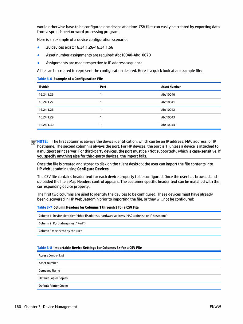
would otherwise have to be configured one device at a time. CSV files can easily be created by exporting datafrom a spreadsheet or word processing program.
Here is an example of a device configuration scenario:
● 30 devices exist: 16.24.1.26-16.24.1.56
● Asset number assignments are required: Abc10040-Abc10070
● Assignments are made respective to IP address sequence
A file can be created to represent the configuration desired. Here is a quick look at an example file:
Table 3-6 Example of a Configuration File
IP Addr Port Asset Number
16.24.1.26 1 Abc10040
16.24.1.27 1 Abc10041
16.24.1.28 1 Abc10042
16.24.1.29 1 Abc10043
16.24.1.30 1 Abc10044
NOTE: The first column is always the device identification, which can be an IP address, MAC address, or IPhostname. The second column is always the port. For HP devices, the port is 1, unless a device is attached toa multiport print server. For third-party devices, the port must be <Not supported>, which is case-sensitive. Ifyou specify anything else for third-party devices, the import fails.
Once the file is created and stored to disk on the client desktop; the user can import the file contents intoHP Web Jetadmin using Configure Devices.
The CSV file contains header text for each device property to be configured. Once the user has browsed anduploaded the file a Map Headers control appears. The customer specific header text can be matched with thecorresponding device property.
The first two columns are used to identify the devices to be configured. These devices must have alreadybeen discovered in HP Web Jetadmin prior to importing the file, or they will not be configured:
Table 3-7 Column Headers for Columns 1 through 3 for a CSV File
Column 1: Device Identifier (either IP address, hardware address (MAC address), or IP hostname)
Column 2: Port (always just “Port”)
Column 3+: selected by the user
Table 3-8 Importable Device Settings for Columns 3+ for a CSV File
Access Control List
Asset Number
Company Name
Default Copier Copies
Default Printer Copies
160 Chapter 3 Device Management ENWW
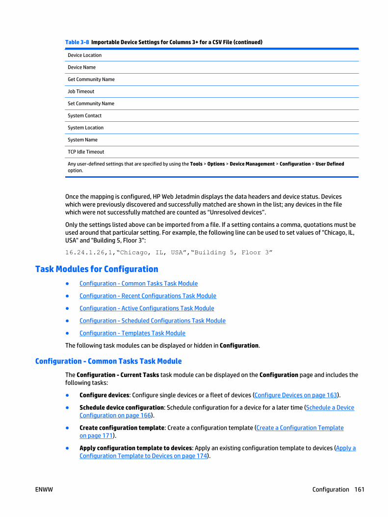
Table 3-8 Importable Device Settings for Columns 3+ for a CSV File (continued)
Device Location
Device Name
Get Community Name
Job Timeout
Set Community Name
System Contact
System Location
System Name
TCP Idle Timeout
Any user-defined settings that are specified by using the Tools > Options > Device Management > Configuration > User Definedoption.
Once the mapping is configured, HP Web Jetadmin displays the data headers and device status. Deviceswhich were previously discovered and successfully matched are shown in the list; any devices in the filewhich were not successfully matched are counted as “Unresolved devices”.
Only the settings listed above can be imported from a file. If a setting contains a comma, quotations must beused around that particular setting. For example, the following line can be used to set values of "Chicago, IL,USA" and "Building 5, Floor 3":
16.24.1.26,1,“Chicago, IL, USA”,“Building 5, Floor 3”
Task Modules for Configuration
● Configuration - Common Tasks Task Module
● Configuration - Recent Configurations Task Module
● Configuration - Active Configurations Task Module
● Configuration - Scheduled Configurations Task Module
● Configuration - Templates Task Module
The following task modules can be displayed or hidden in Configuration.
Configuration - Common Tasks Task Module
The Configuration - Current Tasks task module can be displayed on the Configuration page and includes thefollowing tasks:
● Configure devices: Configure single devices or a fleet of devices (Configure Devices on page 163).
● Schedule device configuration: Schedule configuration for a device for a later time (Schedule a DeviceConfiguration on page 166).
● Create configuration template: Create a configuration template (Create a Configuration Templateon page 171).
● Apply configuration template to devices: Apply an existing configuration template to devices (Apply aConfiguration Template to Devices on page 174).
ENWW Configuration 161
● Edit configuration template: Make changes to an existing configuration template (Edit a ConfigurationTemplate on page 172).
● Delete configuration template: Delete a configuration template (Delete a Configuration Templateon page 173).
● Copy configuration template: View all of the configuration tasks which have occurred on all deviceswithin the retention period (Copy Template Wizard on page 85).
● View configuration history: View all of the configuration tasks which have occurred on all deviceswithin the retention period (View Configuration History on page 165).
The Configuration - Current Tasks task module can be displayed in other areas of HP Web Jetadmin; in theother areas it is Configuration - Common Tasks.
Configuration - Recent Configurations Task Module
The Configuration - Recent Configurations task module shows the recent configurations. You can select aconfiguration task and choose one of the following:
● Details: View details of the selected task.
● View History: View all of the configuration tasks which have occurred on all devices within the retentionperiod (View Configuration History on page 165).
Configuration - Active Configurations Task Module
The Configuration - Active Configurations task module shows the active, or currently running,configurations. You can select a configuration task and choose one of the following:
● Stop: Stops the current configuration task in progress, preventing any devices which have not yet beenconfigured from being configured. To stop multiple tasks, use Ctrl-Enter or Shift-Enter and then clickStop.
● View: View the selected configuration task in progress, including detailed results.
Configuration - Scheduled Configurations Task Module
The Configuration - Scheduled Configurations task module shows the configurations that are scheduled.You can select a configuration task and choose one of the following:
● Delete: Delete the selected configuration.
● Edit: Make changes to the selected configuration.
Configuration - Templates Task Module
The Configuration - Templates task module shows the configuration templates that have been created. Youcan select a configuration template and choose one of the following:
● Apply: Apply the selected configuration template to devices (Apply a Configuration Template to Deviceson page 174).
● Create: Create a configuration template (Create a Configuration Template on page 171).
● Delete: Delete a configuration template (Delete a Configuration Template on page 173).
● Edit: Make changes to a configuration template (Edit a Configuration Template on page 172).
● View: View a configuration template (View a Configuration Template to Devices on page 173).
162 Chapter 3 Device Management ENWW
Related Application Options for Configuration Management
Global settings can be set here for fleet configurations:
● Configure the Retry Settings for Device Configuration Schedules on page 58
● Restore the Default Configuration Templates on page 58
● Manage the User-defined Device Configuration Settings on page 59
Configure Devices
● Steps to Configure Devices
● Other Ways to Configure Devices
You can configure devices without using a configuration template.
Steps to Configure Devices
1. In the left navigation pane, click on Configuration.
In the Configuration - Common Tasks task module, select Configure devices. The Configure Deviceswizard is started with the Specify configuration options page displayed.
2. Select one of the options:
● Use template: Devices will be configured by applying settings from a template. Select aconfiguration template from the drop-down box and go to Step 3.
● Specify settings: Devices will be configured by specifying settings in the wizard. Go to Step 3.
● Import from file: Devices will be configured by importing settings from a CSV file. (See Importing aConfiguration from a File on page 159.)
◦ Click Next. The Select CSV file page is displayed.
◦ Type the path and name of the CSV file to import, or browse for the file. Click Next. Ifsuccessful, it shows you the headers from the CSV file.
NOTE: If any errors are found in the CSV file, you will need to correct them and then try thisimport procedure again.
◦ Select the comparable device setting for each header. Click Next. The Confirm page isdisplayed.
◦ Click Configure devices. The Results page is displayed. Click Done to display theConfiguration page.
NOTE: For more information about the Confirm and Results pages, see Complex Data in theConfirm, Results, and Configuration History Pages on page 159.
3. To schedule the configuration for a later time, click Schedule configuration.
NOTE: If you schedule a task (for example, a discovery or a configuration or others) using acorresponding template, the task uses the settings defined in the template at the time the task starts.This makes it easy to redefine settings used in a regularly scheduled task without having to delete andcreate a scheduled task.
NOTE: All schedules use the date and time on the server where HP Web Jetadmin is installed. Theclient used to access HP Web Jetadmin might not be in the same time zone as the server where HP WebJetadmin is installed. You should be aware of the potential for time and date differences whenconfiguring schedules.
ENWW Configuration 163
NOTE: Scheduled tasks are displayed in the Scheduled Tasks task module on the Device, Discovery,Configuration, Firmware, Reports, Storage, Solutions, and Application Management pages. You canalso display any task module on the Overview page.
4. Click Next. The Select devices page is displayed.
5. Select the device by highlighting it and clicking the arrow buttons between the two lists. To selectmultiple devices, use either Ctrl+Click or Shift+Click. To move all devices from one list to the other, usethe double arrow buttons. You can sort the list of available devices by clicking the column headers, orview more columns by right-clicking the column headers.
You can also select an entire group instead of individual devices, by changing the selection method toGroups. Tasks (for example configurations and more) can be performed on a single group or a groupand all of its subgroups.
NOTE: Including all subgroups can potentially take much longer and cause much more network traffic,so it should be used only when appropriate.
If you schedule a task using a group, the task will apply to the devices in the group at the time the taskstarts. This makes it easy to redefine the devices used in regularly scheduled tasks without having todelete and create a scheduled task.
NOTE: The columns displayed on the Select devices page are defined in View > Preferences > DeviceIdentification.
Click Next. If you chose to specify settings, the Specify device settings page is displayed.
6. The settings displayed are the ones supported by the devices selected in Step 5. Settings are organizedalphabetically within each category. You can also use the personalized My Settings category to easilyfind your favorite settings. If My Settings is not visible, then right-click and select Show ‘My Settings’.Select the configuration options and then click Next.
NOTE: For information about specific configuration options that might not work properly in a batchmode, see Captured Configurable Options and Configuration Templates on page 170.
If you chose to schedule this configuration, the Specify schedule options page is displayed.
If you did not choose to schedule this configuration, go to Step 8.
7. Select the start date and time for your configuration, specify how often it should run, and give it aname. Configuration schedules can have the following flexible settings applied:
● Name: Enter a name for this scheduled task, for easier identification in the task modules and theconfiguration history.
● Start time: Specifies when the configuration will launch.
● Recurrence, Once: Launches only once in the specified schedule.
● Recurrence, Daily: Task will recur daily once per day or once per weekday depending on theselected setting.
● Recurrence, Weekly: Task will recur once every X weeks on the day specified depending on thesetting.
● Recurrence, Monthly: Task will recur once every X months on XX day depending on setting; or,task will recur on specified day pattern depending on setting.
Click Next. The Confirm page is displayed.
NOTE: For more information about the Confirm page, see Complex Data in the Confirm, Results, andConfiguration History Pages on page 159.
164 Chapter 3 Device Management ENWW
8. Review the settings selected. If you did not choose to schedule this configuration, go to step 10.
9. Click Create Schedule. The Results page is displayed.
NOTE: For more information about the Results page, see Complex Data in the Confirm, Results, andConfiguration History Pages on page 159.
At this point, the schedule has been created but the devices have not yet been configured. You maywant to run the configuration once to make sure there are no problems, such as devices needingcredentials in order to be configured. This will increase the chances of the scheduled configurationcompleting successfully. If you do not want to run the configuration now, uncheck the option Runconfiguration now (recommended) and click Done to display the Configuration page. Otherwise, youwill be taken to a second Configuration page.
10. Click Configure Devices. The Results page is displayed. To see details of the configuration, clickDetails. Then click Close.
NOTE: For more information about the Results page, see Complex Data in the Confirm, Results, andConfiguration History Pages on page 159.
Click Done to display the Configuration page.
Other Ways to Configure Devices
● In the left navigation pane, right-click on Configuration and select Configure devices.
● In any device list, select one or more devices; right-click, select Configuration, and then selectConfigure devices.
● In the Configuration - Recent Configurations task module, select a recent configuration, right-click andselect Configure devices.
● To configure devices using a template, in any device list, select one or more devices. Then select theConfig tab and click Apply Template.
● In any device list, select one or more devices; select the Config tab at the bottom of the page. Makechanges to configuration settings on the tab and click Apply.
View Configuration History
● Steps to View Configuration History
● Other Ways to View Configuration History
Any device configuration result is added to configuration history.
Steps to View Configuration History
1. In the left navigation pane, expand Configuration and then click History. The Configuration Historypage is displayed.
NOTE: For more information about the Configuration History page, see Complex Data in the Confirm,Results, and Configuration History Pages on page 159.
2. Select the way you want to group the history results:
● None: Shows all the history as a flat list, which can be sorted by column.
● Task: Shows configurations according to task name, which can only be changed on scheduledtasks.
● Device: Shows configurations by device.
ENWW Configuration 165
● Initiator: Shows configurations according to the user who initiated them.
● Start time: Shows configurations according to start time.
● Device result: Shows configurations according to the device results, to easily find device failures.
● Task result: Shows configurations according to the overall task result.
Other Ways to View Configuration History
● In the left navigation pane, click Configuration. In the Configuration - Common Tasks task module,select View configuration history.
● In the Configuration - Recent Configurations task module, select View History.
● In the left navigation pane, right-click on Configuration and select View configuration history.
● In the left navigation pane, right-click on Overview. Select Configuration > View configuration history.
● In any device list, select one or more devices. Then right-click and select Configuration > Viewconfiguration history to view the history for just those devices.
● In any device list, select one or more devices. Select the Config tab at the bottom of the page. Thenselect View History to view the history for just those devices.
● In any device list, select one or more devices and select the Troubleshoot tab. In the Troubleshootingtools drop-down select Recent Configurations and click View History to view the history for just thosedevices.
Schedule a Device Configuration
● Steps for Scheduling a Device Configuration
● Other Ways to Schedule a Device Configuration
Configurations can be scheduled to occur at the time and day you specify. Like other scheduling withinHP Web Jetadmin, configuration schedules can have the following flexible settings applied:
NOTE: If you schedule a task (for example, a discovery or a configuration or others) using a correspondingtemplate, the task uses the settings defined in the template at the time the task starts. This makes it easy toredefine settings used in a regularly scheduled task without having to delete and create a scheduled task.
NOTE: All schedules use the date and time on the server where HP Web Jetadmin is installed. The clientused to access HP Web Jetadmin might not be in the same time zone as the server where HP Web Jetadmin isinstalled. You should be aware of the potential for time and date differences when configuring schedules.
NOTE: Scheduled tasks are displayed in the Scheduled Tasks task module on the Device, Discovery,Configuration, Firmware, Reports, Storage, Solutions, and Application Management pages. You can alsodisplay any task module on the Overview page.
● Name: Allows flexible naming of scheduled tasks.
● Start time: Specifies when the configuration will launch.
● Recurrence, Once: Launches only once in the specified schedule.
● Recurrence, Daily: Will recur daily once per day or once per weekday depending on setting.
● Recurrence, Weekly: Will recur every X weeks depending on setting.
● Recurrence, Monthly: Will recur once every X months on XX day depending on setting; or, task will recuron specified day pattern depending on setting.
166 Chapter 3 Device Management ENWW
Once a configuration task is scheduled it can be viewed in the Configuration - Scheduled Configurationstask module. Running tasks can be viewed in Configuration - Active Configurations task module.
Steps for Scheduling a Device Configuration
NOTE: All schedules use the date and time on the server where HP Web Jetadmin is installed. The clientused to access HP Web Jetadmin might not be in the same time zone as the server where HP Web Jetadmin isinstalled. You should be aware of the potential for time and date differences when configuring schedules.
1. In the left navigation pane, click on Configuration.
In the Configuration - Common Tasks task module, select Schedule device configuration. TheSchedule Device Configuration wizard is started with the Specify configuration options pagedisplayed.
2. Select one of the options:
● Use template: Devices will be configured by applying settings from a template. Select aconfiguration template from the drop-down box and go to Step 3.
● Specify settings: Devices will be configured by specifying settings in the wizard. Go to Step 3.
● Import from file: Devices will be configured by importing settings from a CSV file. (See Importing aConfiguration from a File on page 159.)
◦ Click Next. The Select CSV file page is displayed.
◦ Type the path and name of the CSV file to import, or browse for the file. Click Next. Ifsuccessful, it shows you the headers from the CSV file.
NOTE: If any errors are found in the CSV file, you will need to correct them and then try thisimport procedure again.
◦ Select the comparable device setting for each header. Click Next. The Confirm page isdisplayed.
◦ Click Configure devices. The Results page is displayed. Click Done to display theConfiguration page.
3. Click Next. The Select devices page is displayed.
4. Select the device by highlighting it and clicking the arrow buttons between the two lists. To selectmultiple devices, use either Ctrl+Click or Shift+Click. To move all devices from one list to the other, usethe double arrow buttons. You can sort the list of available devices by clicking the column headers, orview more columns by right-clicking the column headers.
You can also select an entire group instead of individual devices, by changing the selection method toGroups. Tasks (for example configurations and more) can be performed on a single group or a groupand all of its subgroups.
NOTE: Including all subgroups can potentially take much longer and cause much more network traffic,so it should be used only when appropriate.
If you schedule a task using a group, the task will apply to the devices in the group at the time the taskstarts. This makes it easy to redefine the devices used in regularly scheduled tasks without having todelete and create a scheduled task.
NOTE: The columns displayed on the Select devices page are defined in View > Preferences > DeviceIdentification.
Click Next. If you chose to specify settings, the Specify device settings page is displayed.
ENWW Configuration 167
5. The settings displayed are the ones supported by the devices selected in Step 4. Settings are organizedalphabetically within each category. You can also use the personalized My Settings category to easilyfind your favorite settings. If My Settings is not visible, then right-click and select Show ‘My Settings’.Select the configuration options and then click Next.
NOTE: For information about specific configuration options that might not work properly in a batchmode, see Captured Configurable Options and Configuration Templates on page 170.
6. Select the start date and time for your configuration, specify how often it should run, and give it aname. Configuration schedules can have the following flexible settings applied:
● Name: Enter a name for this scheduled task, for easier identification in the task modules and theconfiguration history.
● Start time: Specifies when the configuration will launch.
● Recurrence, Once: Launches only once in the specified schedule.
● Recurrence, Daily: Task will recur daily once per day or once per weekday depending on theselected setting
● Recurrence, Weekly: Task will recur once every X weeks on the day specified depending on thesetting.
● Recurrence, Monthly: Task will recur once every X months on XX day depending on setting; or,task will recur on specified day pattern depending on setting.
Click Next. The Confirm page is displayed.
7. Review the settings selected.
8. Click Create Schedule. The Results page is displayed.
At this point, the schedule has been created but the devices have not yet been configured. You maywant to run the configuration once to make sure there are no problems, such as devices needingcredentials in order to be configured. This will increase the chances of the scheduled configurationcompleting successfully. If you do not want to run the configuration now, uncheck the option Runconfiguration now (recommended) and click Done to display the Configuration page. Otherwise, youwill be taken to a second Configuration page.
9. Click Configure Devices. The Results page is displayed. To see details of the configuration, clickDetails. Then click Close.
Click Done to display the Configuration page.
Other Ways to Schedule a Device Configuration
● In any device list, select one or more devices; right-click and select Configuration > Scheduleconfiguration.
● In the left navigation pane, right-click on Configuration and select Schedule configuration.
● In the left navigation pane, right-click on Overview and select Configuration > Schedule configuration.
● In many of the methods for Configuring a device or Applying a template, you also have the option ofscheduling that task by checking Schedule configuration on the first page of the wizard.
Configuration Templates
● Volatile Configuration and HP Web Jetadmin Configuration Templates
● Adding Configuration Templates to a Group Policy
168 Chapter 3 Device Management ENWW
● Captured Configurable Options and Configuration Templates
Configuration templates are used to store device settings and apply those settings to one or more devices.This can be done to keep device configurations consistent and to make it easy to apply a common set ofsettings on a regular basis. Templates are an easy way to change the settings for regularly scheduledconfigurations, without having to recreate the entire schedule. Templates can also be used to save manysettings from a device, either for backup purposes or to apply to similar devices.
You can create and manage configuration templates:
● Create configuration template: Create a configuration template (Create a Configuration Templateon page 171).
● Apply configuration template to devices: Apply the selected configuration template to devices (Applya Configuration Template to Devices on page 174).
● Edit configuration template: Make changes to an existing configuration template (Edit a ConfigurationTemplate on page 172).
● Delete configuration template: Delete a configuration template (Delete a Configuration Templateon page 173).
● Copy configuration template: Copy a configuration template and rename the new template and makechanges to it (Copy Template Wizard on page 85).
● Export configuration templates: Export a configuration template to a file and then import it into adifferent instance of HP Web Jetadmin running on a different server (Export and Import DeviceConfiguration Templates on page 86).
● Import configuration templates: After a configuration template has been exported, you can thenimport it to use it on a different instance of HP Web Jetadmin running on a different server (Export andImport Device Configuration Templates on page 86).
Volatile Configuration and HP Web Jetadmin Configuration Templates
Some actions performed remotely on devices can cause the device to automatically power cycle or change insome other way that can impact the success of further configuration. Consider the case where you areattempting to configure several device parameters, including one parameter that causes the device to resetitself, which also causes HP Web Jetadmin to lose communication with the device for a time. Changing adevice's IP parameters is a good example. The device (in many cases) re-initializes and stops communicatingfor a time.
HP Web Jetadmin has several configuration elements that are known to cause device interrupts and,therefore, cause a configuration to become volatile or unstable. These items are programmatically marked insuch a way that HP Web Jetadmin always uses them last in a configuration. These configuration items are:
● Security > LDAP - Accessing the Server
● Digital Sending > Activity Log
● Fax > Fax Reports and Logs (print or clear activity log)
● Security > Disable Direct Ports
● Network > Protocol Stacks
● Network > IPv4 Information, which includes Subnet Mask and Gateway (both single and batchconfigurations)
● Wireless > 802.11 a/b/g
● Network > Link Setting
ENWW Configuration 169
● File System > File System Password
● Security > Get Community Name
● Security > Set Community Name
● Security > SNMP Version Access Control
In any configuration, whether it is performed for a single device, for multiple devices, or with a configurationtemplate, these settings are always sent to the device last to improve the chance of successfulconfigurations. The following considerations should be made with these settings:
● The chances of a configuration failure increase when these settings are used in the same configuration.
● HP Web Jetadmin only marks these items to run last. HP Web Jetadmin does not put these items in anyorder relative to the other items listed here.
● Device behaviors, while sometimes predictable, are not fully documented with these knownconfiguration items.
In summary, not all of the HP Web Jetadmin configurations can guarantee a positive and stable result at thephysical device. You might need to test individual configuration options to understand the effects on variousHP device models and determine if an HP Web Jetadmin configuration is successful. HP will continue besteffort practices in documenting these and other known configuration characteristics.
Adding Configuration Templates to a Group Policy
Configuration templates can be added to Group policies. Group policies are a powerful new automation toolthat can save you a great deal of time configuring devices and HP Web Jetadmin settings. Any device groupcan have a property known as Group Policy. One type of group policy is Configure Devices, which uses aselected configuration template from the list of existing templates. The configuration template can beapplied either as the device is added into the group or as the device is removed from the group. MultipleConfigure Devices Group Policies using different templates can exist on a single device group.
Captured Configurable Options and Configuration Templates
Some configuration options behave differently for single-device configuration than they do for multiple-device configuration. When capturing device settings into a configuration template via the Save As Templatefeature, some configuration options will fail when the template is used to configure multiple devices. Theconfiguration options that will fail when used to configure multiple devices via a stored configurationtemplate are the following:
● Tray Administration
● Authentication Manager
● Control Panel Language
● Default Media Type
● SNMP Trap Destination Table
● Access Control List
● IPv6 Options
● Asset Number
● System Name
● IP Address
● LAA Address Configuration
170 Chapter 3 Device Management ENWW
When capturing device settings via the Save As Template feature, these items should remain unchecked. If itis desired to have these configuration options as part of the template, an edit can be performed on thetemplate after it has been saved and the desired configuration option can be selected and configuredappropriately. Once the modified template is saved, a version of the configuration option that supportsmultiple configuration will be used and the operation should succeed. This situation will not occur duringnormal use of multiple device configuration or when a configuration template is created independently froma device.
Create a Configuration Template
● Steps to Create a Configuration Template
● Other Ways to Create a Configuration Template
Configuration templates are used to store device settings and apply those settings to one or more devices.This can be done to keep device configurations consistent and to make it easy to apply a common set ofsettings on a regular basis. Templates are an easy way to change the settings for regularly scheduledconfigurations, without having to recreate the entire schedule. Templates can also be used to save manysettings from a device, either for backup purposes or to apply to similar devices.
Steps to Create a Configuration Template
1. In the Device Management navigation pane, right-click Configuration, and then select Createconfiguration template. The Create Device Configuration Template wizard starts.
2. On the Select Template Models page, select the device models to configure, and then click the rightarrow button.
3. Select the network cards to configure, and then click the right arrow button.
4. Click Next. The Specify template options page appears, listing only the configuration options thatapply to the device models and network cards you selected.
5. Enter the name of the template (up to 48 characters).
6. Specify the settings for the configuration options to include in the template, and then click Next.
NOTE: If you click Back, any configuration settings you already specified might be lost when youreturn to the Specify template options page. If you remove any device models or network cards on theSelect Template Models page, some configuration options might not be available when you return tothe Specify template options page. If you add device models or network cards on the Select TemplateModels page, new configuration options might be available when you return to the Specify templateoptions page.
NOTE: For information about specific configuration options that might not work properly in a batchmode, see Captured Configurable Options and Configuration Templates on page 170.
NOTE: The configuration options selected for this template will only be applied to those devices thatsupport the options.
7. On the Confirm page, verify that the configuration option settings are correct, and then click CreateTemplate.
8. On the Results page, click the Done button.
ENWW Configuration 171
Other Ways to Create a Configuration Template
● In the left navigation pane, right-click on Configuration and select Create configuration template.
● In the left navigation pane, expand Configuration and right-click Templates. Then select Createconfiguration template.
● In the Configuration - Templates task module, select Create.
● In the left navigation pane, right-click on Overview and select Configuration > Create configurationtemplate.
● In the left navigation pane, expand Configuration and select Templates. Click Create next to the list oftemplates displayed.
● In any device list, select one or more devices and click the Config tab at the bottom of the page. Selectthe configuration options and then click Save as Template.
Edit a Configuration Template
● Steps to Edit a Configuration Template
● Other Ways to Edit a Configuration Template
You can make changes to any configuration template after is has been created.
Steps to Edit a Configuration Template
1. In the Device Management navigation pane, right-click Configuration, and then select Editconfiguration template. The Edit Device Configuration Template wizard starts.
2. On the Select template page, select the template, and then click Next.
3. On the Select Template Models page, change the device models and network cards included in thetemplate, and then click Next.
NOTE: If you change the device models and network cards included in the template, any configurationsettings you already specified for the template might be lost. If you remove any device models ornetwork cards, some configuration options might no longer be available. If you add device models ornetwork cards, new configuration options might now be available.
4. On the Specify template options page, enter a new name for the template (up to 48 characters).
5. Specify the settings for the configuration options to include in the template, and then click Next.
NOTE: For information about specific configuration options that might not work properly in a batchmode, see Captured Configurable Options and Configuration Templates on page 170.
NOTE: The configuration options selected for this template will only be applied to those devices thatsupport the options.
6. On the Confirm page, verify that the configuration option settings are correct, and then click SaveTemplate.
7. On the Results page, click the Done button.
Other Ways to Edit a Configuration Template
● In the left navigation pane, right-click on Configuration and select Edit configuration template.
● In the left navigation pane, expand Configuration and then expand Templates. Right-click on thetemplate to edit and select Edit configuration template.
172 Chapter 3 Device Management ENWW
● In the left navigation pane, expand Configuration and then expand Templates. Select the template toedit and click Edit on the page displaying the template settings.
● In the Configuration - Templates task module, select the template to edit and click Edit.
● In the left navigation pane, expand Configuration and then select Templates. Select the template toedit from the list displayed and click Edit.
Delete a Configuration Template
● Steps to Delete a Configuration Template
● Other Ways to Delete a Configuration Template
Configuration templates can be deleted.
Steps to Delete a Configuration Template
1. In the left navigation pane, click on Configuration. In the Configuration - Common Tasks task module,select Delete configuration template. The Delete Device Configuration Template wizard is startedwith the Select template page displayed.
2. Select the template to delete and click Next. The Confirm page is displayed.
3. Click Delete Template. The Results page is displayed.
Click Done to display the Configuration page.
Other Ways to Delete a Configuration Template
● In the left navigation pane, right-click on Configuration and select Delete configuration template.
● In the left navigation pane, expand Configuration and then expand Templates. Select the template todelete and click Delete on your keyboard.
● In the left navigation pane, expand Configuration and then expand Templates. Right-click on thetemplate to delete and select Delete configuration template.
● In the Configuration - Templates task module, select the template to delete and click Delete.
● In the left navigation pane, expand Configuration and then select Templates. Select the template todelete from the list displayed and click Delete.
Copy a Configuration Template
Throughout Device Management view, templates can be created and managed to save you time and provideconsistency. Templates contain configuration preferences (that vary by template type) and can be applied todevices or groups. Templates are available in Configuration, Alerts, Discovery, Data Collection, and ReportGeneration. For more information, see Copy Template Wizard on page 85.
View a Configuration Template to Devices
● Steps to View a Configuration Template
● Other Ways to View a Configuration Template to Devices
You can view existing configuration templates.
ENWW Configuration 173
Steps to View a Configuration Template
1. In the left navigation pane, expand Configuration and then expand Templates. Click on the templateyou want to view. The template page is displayed.
2. You can view all of the settings for the template. You can also:
● Apply: Apply the selected configuration template to devices (Apply a Configuration Template toDevices on page 174).
● Edit: Make changes to an existing configuration template (Edit a Configuration Templateon page 172).
● New: Create a configuration template (Create a Configuration Template on page 171).
● Delete: Delete a configuration template (Delete a Configuration Template on page 173).
Other Ways to View a Configuration Template to Devices
● In the Configuration - Templates task module, select the template to view and click View.
Apply a Configuration Template to Devices
● Steps to Apply a Configuration Template to Devices
● Other Ways to Apply a Configuration Template to Devices
When you apply a configuration template, HP Web Jetadmin configures the devices with the settings storedin the template.
The following are the results you can expect when applying a template:
● The template contains configuration options for a single device model or network card.
If you apply the template to a device model or network card that is specified in the template, all theconfiguration options are valid and HP Web Jetadmin applies the configuration options to the device.
If you apply the template to a device model or network card that is not specified in the template, theresults are not guaranteed. Other device models and network cards might not support the configurationoptions specified in the template. If the device model or network card supports a configuration optionspecified in the template, HP Web Jetadmin applies that configuration option to the device. If the devicemodel or network card does not support a configuration option specified in the template,HP Web Jetadmin does not apply that configuration option to the device and displays Not Supported forthat configuration option on the Results page.
● The template contains configuration settings for multiple device models and network cards.
When you apply the template, the results depend on the configuration options specified in the templateand the device models and network cards to which you apply the template.
If the configuration options specified in the template are common to all the device models and networkcards specified in the template, HP Web Jetadmin applies all the configuration options when you applythe template to those device models and network cards.
However, all the configuration options might not be valid for all the device models and network cardsspecified in the template. For example, assume that the template includes one device model thatsupports the fax functionality and one device model does not support the fax functionality. If you applythe template to the device model that supports the fax functionality, HP Web Jetadmin applies the faxconfiguration options specified in the template to the device. If you apply the template to the devicemodel that does not support the fax functionality, HP Web Jetadmin does not apply the fax
174 Chapter 3 Device Management ENWW
configuration options specified in the template to the device and displays Not Supported for thoseconfiguration options on the Results page.
To determine if a device model or network card supports the configuration options specified in the template,edit the template. For instructions, see Edit a Configuration Template on page 172. For each configurationoption in the template, hold the cursor over the configuration option title. A list of device models andnetwork cards that support that configuration option appears.
Steps to Apply a Configuration Template to Devices
1. In the left navigation pane, click Configuration. In the Configuration - Common Tasks task module,select Apply configuration template to devices. The Apply Device Configuration Template wizard isstarted with the Specify configuration options page displayed.
2. Select the configuration template from the drop-down box.
3. If you want to schedule this configuration to run at a later time, select Schedule configuration. ClickNext; the Select devices page is displayed.
NOTE: If you schedule a task (for example, a discovery or a configuration or others) using acorresponding template, the task uses the settings defined in the template at the time the task starts.This makes it easy to redefine settings used in a regularly scheduled task without having to delete andcreate a scheduled task.
NOTE: All schedules use the date and time on the server where HP Web Jetadmin is installed. Theclient used to access HP Web Jetadmin might not be in the same time zone as the server where HP WebJetadmin is installed. You should be aware of the potential for time and date differences whenconfiguring schedules.
NOTE: Scheduled tasks are displayed in the Scheduled Tasks task module on the Device, Discovery,Configuration, Firmware, Reports, Storage, Solutions, and Application Management pages. You canalso display any task module on the Overview page.
4. Select the device by highlighting it and clicking the arrow buttons between the two lists. To selectmultiple devices, use either Ctrl+Click or Shift+Click. To move all devices from one list to the other, usethe double arrow buttons. You can sort the list of available devices by clicking the column headers, orview more columns by right-clicking the column headers.
You can also select an entire group instead of individual devices, by changing the selection method toGroups. Tasks (for example configurations and more) can be performed on a single group or a groupand all of its subgroups.
NOTE: Including all subgroups can potentially take much longer and cause much more network traffic,so it should be used only when appropriate.
If you schedule a task using a group, the task will apply to the devices in the group at the time the taskstarts. This makes it easy to redefine the devices used in regularly scheduled tasks without having todelete and create a scheduled task.
NOTE: The columns displayed on the Select devices page are defined in View > Preferences > DeviceIdentification.
Click Next. The Confirm page is displayed.
5. Review the settings selected. Click Apply Template. The Results page is displayed.
6. To see details of the configuration, click Details. Then click Close.
Click Done to display the Configuration page.
ENWW Configuration 175
Other Ways to Apply a Configuration Template to Devices
● In the left navigation pane, expand Configuration and then expand Templates to list all of theconfiguration templates. You can drag-and-drop one or more devices onto one of the configurationtemplates listed under Templates.
● In the left navigation pane, right-click on Configuration and select Apply configuration template.
● In any device list, select one or more devices. Then right-click and select Configuration > Applyconfigure template.
● In the Configuration - Templates task module, select the template to apply and click Apply.
● In the left navigation pane, expand Configuration and then select Templates. Select the template youwish to apply from the displayed list and click Apply.
● In the left navigation pane, expand Configuration and then expand Templates. Right-click on thetemplate you wish to apply in the navigation tree and select Apply configuration template.
Alerts● All About Alerts
● Alerts Traps Listener Port
● Task Modules for Alerts
● Related Application Options for Alerts
● Managing Device Alerts
● Create Alert Subscriptions
● Edit Alert Subscriptions
● Copy an Alert Subscription Template
● Alert History
● Alert Subscription Templates
● Create Alert Subscription Templates
● Apply an Alert Subscription Template
● Edit Alert Subscription Templates
● Delete an Alert Subscription Template
● All Subscriptions
All About Alerts
● Alerts and HP Web Jetadmin
● What You Can Do With Alerts
● Types of Alerts
● Examples of Alerts
HP Web Jetadmin can detect different events occurring on devices and then relay detailed messages aboutthose events, device states, and other important specifics. These messages can be sent to email addresses orto Alerts History within HP Web Jetadmin. For example, error or warning conditions on printers, such as
176 Chapter 3 Device Management ENWW
paper out or toner low, can trigger email messages to be sent by HP Web Jetadmin that contain detailedinformation pertaining to the condition, allowing the recipient to act upon that condition immediately
The advantage of alerts is that you can receive proactive, real-time warnings via email for events that occuron networked printers. Receiving early notification of printer events allows administrators to correct theproblems before they impact end user productivity, saving time for both the administrator and the end user.Helpdesks might use alerts to proactively troubleshoot issues with printers before end users detect them.Individuals responsible for ordering consumables, such as toner cartridges, might enable toner low alerts sothey can be warned of toner low conditions in order to proactively order toner before it runs out.
To ensure this feature works properly, see System Requirements on page 1.
Alerts and HP Web Jetadmin
As in earlier releases of HP Web Jetadmin, proactive alerting is accomplished through detection of an eventbased on a device, processing to determine the appropriate action to take, and then notification throughsome method (usually email). The initial detection of device based events is done in one of two ways:
● Polling devices: Always used for Supplies and for Critical alert types.
Supplies alerts are polled in adaptive intervals, based on the rate of use.
Critical Alerts are polled at the rate designated in Tools > Options > Device Management > DevicePolling > Alerts.
● Traps: Packets sent to HP Web Jetadmin to signal an event. When the device is first established inHP Web Jetadmin Alerts, the trap destination (the application’s IP address) is configured onto thedevice.
The following Alerts features have been added to HP Web Jetadmin:
● Intuitive, easy to use Alerts settings interface
● Multiple subscription control
● Alerts subscription templates
● Supplies alerting
● Backup polling
● Adaptive polling (supplies)
● Alerts history interface
What You Can Do With Alerts
You can use Alerts to have immediate or real-time notification that an event has occurred. A commonscenario is a print maintenance or support team. These people would like to know when a problem happensrather than to wait for a customer complaint. In this way, they can proactively handle trouble perhaps evenprior to the customer experiencing downtime.
In HP Web Jetadmin, you actually subscribe to Alerts to get information about devices. When you subscribeto an Alert, you are requesting information from a device (or devices) about specific settings on that device(or devices) including events, email address notification, and more. (See Create Alert Subscriptionson page 180.)
Types of Alerts
There are three types of Alerts:
ENWW Alerts 177
● General alerts (detailed): Include most non-supply device events and rely on traps. Polling isestablished when traps destinations cannot be configured.
● Supplies alerts: Monitor device supply status and levels through polling. The polling mechanism uses acombination of slow-polling and sliding time interval depending on the level of the supply beingmonitored.
● Critical alerts: Events are monitored by polling every five minutes. The polling interval is configurablewithin the range of 5 to 360 minutes. Because of the frequent polling nature of this solution, it isimportant to use it sparingly and only for devices that need immediate attention. All General Alerts areavailable.
Examples of Alerts
Following are some examples of alerts you might want to configure:
● An alert that is set to add an event to the alert history when a specific printer error occurs.
NOTE: Alerts now support more detailed printer errors such as “Subsystem 72 -- Service Error” andmore.
● An alert set to notify a recipient through email about a Toner Low condition.
● An alert set to notify a recipient through email about a specific supply threshold.
● An alert set to propagate an SNMP trap directed at a listener process on another application such asHP OpenView.
Alerts Traps Listener Port
HP Web Jetadmin uses UDP port 27892 as the traps listener port for alerts and any reports that are based onby-user collections.
Task Modules for Alerts
● Alerts - Current Tasks and Alerts - Common Tasks Task Modules
● Alerts - Active Tasks Task Module
● Alerts - Recent Alerts Task Module
● Alerts - Alert Subscriptions Task Module
● Alerts - Subscription Templates Task Module
The following task modules can be displayed or hidden in Alerts on the Alerts Management page.
Alerts - Current Tasks and Alerts - Common Tasks Task Modules
The Alerts - Current Tasks task module can be displayed on the Alerts Management page and includes thefollowing tasks:
● Create Alert Subscriptions on page 180
● Create Alert Subscription Templates on page 185
● Apply an Alert Subscription Template on page 187
● Edit Alert Subscription Templates on page 188
● Delete an Alert Subscription Template on page 190
● Copy Template Wizard on page 85
178 Chapter 3 Device Management ENWW

The Alerts - Current Tasks task module can be displayed in other areas of HP Web Jetadmin; in the otherareas it is Alerts - Common Tasks.
Alerts - Active Tasks Task Module
The Alerts - Active Tasks task module shows you any alerts currently scheduled. You can:
● Stop an alert by highlighting it and clicking Stop. To stop multiple tasks, use Ctrl-Enter or Shift-Enterand then click Stop.
● View an alert template. The following is displayed:
◦ Task Name: The name of the alert.
◦ State: Whether or not credentials were requested for devices.
◦ Initiator: The name of the user who started the alert.
◦ Start Time: The time the alert should start.
Alerts - Recent Alerts Task Module
View summary information or complete information about alerts history (Alert History on page 184). ClickView History to see the entire Alert History page.
Alerts - Alert Subscriptions Task Module
● Subscribed devices (Create Alert Subscriptions on page 180): How many devices had alertsubscriptions. Also displayed is the percentage of all devices that devices with alert subscriptionsrepresents.
● Unsubscribed devices: How many devices have no alert subscriptions. Also displayed is the percentageof all devices that devices with no alert subscriptions represents.
Alerts - Subscription Templates Task Module
● Apply an Alert Subscription Template on page 187
● Create Alert Subscription Templates on page 185
● Delete an Alert Subscription Template on page 190
● Edit Alert Subscription Templates on page 188
● View (Alert Subscription Templates on page 184)
Related Application Options for Alerts
Configuration settings can be stored here for managing alerts:
● Attach the Supplies Report to the Email Notifications for Supply Alerts on page 65
● Configure the Polling Options for Device Alerts and Supplies Alerts on page 54
● Manage the Custom Email Templates on page 66
● Manage the Templates for Alert Subscriptions on page 66
● Configure the Format for SNMP Traps on page 67
ENWW Alerts 179
Managing Device Alerts
When alerts have been configured for a device, they are entered on a Trap Table. (Traps are set only onGeneral alerts, see Create Alert Subscriptions on page 180). Depending on the device, the trap table willcontain up to 3, 6, or 12 for that device. HP Web Jetadmin will not automatically overwrite any traps in thetable. When a Trap Table is full, the Edit trap table settings dialog box is displayed, which lets you managethe alerts for that device. You can:
● Remove all trap table settings: Removes all traps from the table and allows new ones to be added.
● Remove selected trap table settings: Removes selected traps from the table and allows new ones tobe added.
● Skip this device: Leaves the trap table full so new alerts will not be added for this device.
The Edit trap table settings dialog box will be displayed within HP Web Jetadmin as soon as the Trap Tablefor the device becomes full. If alerts were set up with a schedule, with a Group Policies on page 112, or forDevice Utilization by User and Data Collections on page 210, the Edit trap table settings dialog box will beaccessible through the Alerts - Active Tasks Task Module on page 179 so that you can take action on them atyour convenience.
Create Alert Subscriptions
You can define alerts for one or more devices. Traps are sent only on General alerts.
NOTE: When the maximum number of alerts have been stored for a device, the Edit trap table settingsdialog box is displayed so that you can manage the alerts in the table. For more information, see ManagingDevice Alerts on page 180.
To create alert subscriptions, perform the following steps:
1. In the Device Management navigation pane, right-click Alerts, and then select Subscribe. The CreateAlert Subscription wizard starts.
2. On the Specify alerts subscription type page, select one of the following options:
● Select a template from the drop-down box, or
● Specify the alert settings:
◦ General alerts (detailed): Select non-supply device events and rely on traps. Polling isestablished when traps destinations cannot be configured.
◦ Supplies alerts: Monitor selected device supply status and levels through polling. The pollingmechanism uses a combination of slow-polling and sliding time interval depending on thelevel of the supply being monitored.
◦ Critical alerts: Monitor selected events by polling every five minutes. The polling interval isconfigurable within the range of 5 to 360 minutes. Because of the frequent polling nature ofthis solution, it is important to use it sparingly and only for devices that need immediateattention. All General Alerts are available. This and other polling rates are adjustable.
Click Next. The Select devices page is displayed.
3. Select the device by highlighting it and clicking the arrow buttons between the two lists. To selectmultiple devices, use either Ctrl+Click or Shift+Click. To move all devices from one list to the other, use
180 Chapter 3 Device Management ENWW
the double arrow buttons. You can sort the list of available devices by clicking the column headers, orview more columns by right-clicking the column headers.
You can also select an entire group instead of individual devices, by changing the selection method toGroups. Tasks (for example configurations and more) can be performed on a single group or a groupand all of its subgroups.
NOTE: Including all subgroups can potentially take much longer and cause much more network traffic,so it should be used only when appropriate.
If you schedule a task using a group, the task will apply to the devices in the group at the time the taskstarts. This makes it easy to redefine the devices used in regularly scheduled tasks without having todelete and create a scheduled task.
NOTE: The columns displayed on the Select devices page are defined in View > Preferences > DeviceIdentification.
Click Next.
4. If you chose:
● General alerts (detailed) or Critical alerts:
◦ The Select alerts page is displayed. Select the supply alerts you want to monitor.
◦ The Specify advanced settings page is displayed; select the advanced settings (the onesdisplayed are dependent on the alerts selected on the previous page):
No advanced settings: Select this option if you do not want to configure any advancedsettings.
Time to ignore duplicate alerts: When enabled, this value keeps HP Web Jetadmin fromsending duplicate Alerts within the time specified. This setting is specific to the Subscriptionbeing edited or created.
Ignore duplicates for: Specify the amount of time that should elapse beforeHP Web Jetadmin should post an alert to email or to Alerts History.
Ignore first time period: If you want HP Web Jetadmin to ignore the first time period (asindicated in Ignore duplicates for above), then select this option.
● Supplies alerts:
◦ The Select supplies categories page is displayed. Select the supply categories you want tomonitor.
◦ The Select alert threshold page is displayed. Select the threshold value or select Replaced.
The threshold is a decrementing value so that when a supply reaches that level, the alert issent. If the Replaced option is set, then the alert is sent when the supply level increasessignificantly from where is used to be.
5. Click the Next button.
6. On the Specify notification type page, select one of the following options:
NOTE: Alerts will always be included in the Alert History display. Also, when the Log to File feature isenabled, alerts will be written to the Alert Log to File (Configure the Settings for the Alerts Logon page 66).
ENWW Alerts 181
● Alert history only: Enter any alerts into the Alert History Log and do not send any emailmessages about the alerts.
● Email: Sends notifications to the specified email address when the alerts occur. Click the Nextbutton. On the Specify notification settings page, specify the following settings:
◦ Enter the email address or browse for the email address. Multiple email addresses can beseparated by a semi-colon.
◦ Select the email format:
Concise (default): Short description of the received alert.
Verbose: Longer description of the alert.
Custom: Message format that you can create and name for reuse later. If you do not find atemplate in the drop-down list of custom messages, you can create one by clicking CustomEmail Templates.
Proper SMTP settings must be made in Tools > Options > Shared > Email > SMTP (Configure theSMTP Settings on page 41) and Manage the Shared Email Addresses on page 41).
● SNMP trap generator: Forwards SNMP traps to the specified server when the alerts occur. Clickthe Next button. On the Specify notification settings page, specify the following settings:
◦ Trap destination: The IP address or fully qualified domain name of the server where theSNMP traps are forwarded.
◦ Listen port: The port on which the server listens for SNMP traps.
◦ SNMP version: select the desired SNMP trap version.
◦ Community: enter a community name for the trap, if any.
◦ Preferred language: select the preferred language.
◦ To change the format for the SNMP traps, click the Edit button. The Template Contentswindow opens. For more information about the SNMP trap format, see Configure the Formatfor SNMP Traps on page 67.
7. Click the Next button.
8. On the Specify subscription name page, enter a name for the alert subscription, and then click the Nextbutton.
9. On the Confirm page, verify that the information is correct, and then click the Subscribe button.
10. On the Progress page, click the Details button. Review the alerts for each device, and then click theClose button.
NOTE: The Device Trap Table Settings page might be displayed. If so, complete this page and clickFinish.
11. On the Results page, click the Done button.
Edit Alert Subscriptions
After an alerts subscription has been made for a device, changes in existing Notification Settings, emailrecipients and formats, Available Alerts selections, Advanced Settings, and the Subscription Name can bechanged.
To edit alert subscriptions, perform the following steps:
182 Chapter 3 Device Management ENWW
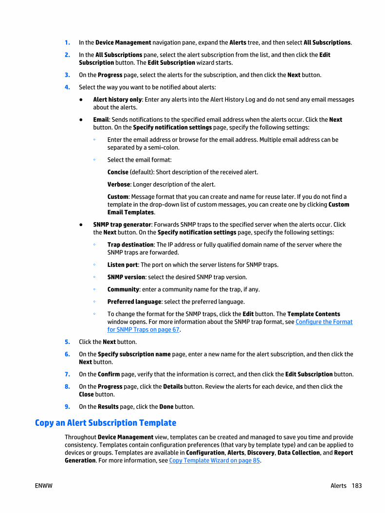
1. In the Device Management navigation pane, expand the Alerts tree, and then select All Subscriptions.
2. In the All Subscriptions pane, select the alert subscription from the list, and then click the EditSubscription button. The Edit Subscription wizard starts.
3. On the Progress page, select the alerts for the subscription, and then click the Next button.
4. Select the way you want to be notified about alerts:
● Alert history only: Enter any alerts into the Alert History Log and do not send any email messagesabout the alerts.
● Email: Sends notifications to the specified email address when the alerts occur. Click the Nextbutton. On the Specify notification settings page, specify the following settings:
◦ Enter the email address or browse for the email address. Multiple email address can beseparated by a semi-colon.
◦ Select the email format:
Concise (default): Short description of the received alert.
Verbose: Longer description of the alert.
Custom: Message format that you can create and name for reuse later. If you do not find atemplate in the drop-down list of custom messages, you can create one by clicking CustomEmail Templates.
● SNMP trap generator: Forwards SNMP traps to the specified server when the alerts occur. Clickthe Next button. On the Specify notification settings page, specify the following settings:
◦ Trap destination: The IP address or fully qualified domain name of the server where theSNMP traps are forwarded.
◦ Listen port: The port on which the server listens for SNMP traps.
◦ SNMP version: select the desired SNMP trap version.
◦ Community: enter a community name for the trap, if any.
◦ Preferred language: select the preferred language.
◦ To change the format for the SNMP traps, click the Edit button. The Template Contentswindow opens. For more information about the SNMP trap format, see Configure the Formatfor SNMP Traps on page 67.
5. Click the Next button.
6. On the Specify subscription name page, enter a new name for the alert subscription, and then click theNext button.
7. On the Confirm page, verify that the information is correct, and then click the Edit Subscription button.
8. On the Progress page, click the Details button. Review the alerts for each device, and then click theClose button.
9. On the Results page, click the Done button.
Copy an Alert Subscription Template
Throughout Device Management view, templates can be created and managed to save you time and provideconsistency. Templates contain configuration preferences (that vary by template type) and can be applied todevices or groups. Templates are available in Configuration, Alerts, Discovery, Data Collection, and ReportGeneration. For more information, see Copy Template Wizard on page 85.
ENWW Alerts 183
Alert History
● Steps for Viewing Alert History
● Other Ways to View Alert History
On the Alert History page, you can view the following information about alerts:
● Time Received: The time the alert was received.
● Alert: the name of the alert.
● Device Model: The model of the device that received the alert.
● IP Hostname: The IP Hostname of the device that received the alert.
● IP Address: The IP Address of the device that received the alert.
You can sort the details by any of the columns listed by dragging that column to the top left of the page.
Steps for Viewing Alert History
1. Expand the Alerts tree in the left navigation pane. In the Alerts - Recent Alerts task module, click ViewHistory. The Alert History page is displayed
2. After you have viewed the history, click Close. The Alerts Management page is displayed.
Other Ways to View Alert History
● Right-click on Alerts in the left navigation pane and select View alerts history.
● Click and expand Alerts in the left navigation pane. Then right-click on History and select View alertshistory.
● In the Alerts - Recent Alerts task module, view summary information, or highlight an alert and clickView History.
● In the All Devices list, highlight the device and then click the Alerts tab in the lower portion of the page.Then select Alert History.
● In the All Devices list, highlight the device and then right-click. Select Alerts > View alerts history.
● Select a device from the device list and select the Troubleshoot tab. Then Recent Alerts from the rightdrop-down list. Click on View History to display the complete log for that device.
Alert Subscription Templates
● Steps for Viewing Alert Subscription Templates
● Other Ways to View an Alert Subscription Template
You can view Alert templates (including the default template) and also do any of the following actions:
● Apply an Alert Subscription Template on page 187
● Create Alert Subscription Templates on page 185
● Delete an Alert Subscription Template on page 190
● Edit Alert Subscription Templates on page 188
184 Chapter 3 Device Management ENWW
Steps for Viewing Alert Subscription Templates
1. Expand the Alerts tree in the left navigation pane and then expand Templates to list all Alerttemplates. Click on the template you want to view. The specific template detail is displayed.
2. You can do any of the following:
● Apply: Apply the template to devices (Apply an Alert Subscription Template on page 187).
● Edit: Make changes to the template (Edit Alert Subscription Templates on page 188).
Other Ways to View an Alert Subscription Template
● Expand the Alerts tree in the left navigation pane and then click on Templates. The Alerts -Subscription Templates page is displayed listing all of the Alert templates. Highlight a template andthen click View.
Create Alert Subscription Templates
Alert templates are used to store settings to be reused again. When an Alert Subscription Template is appliedto a device as a ‘Linked Subscription’, the subscription will be altered if the associated template is changed. Adefault Alerts Subscription Template is pre-configured when HP Web Jetadmin is installed and contains acombination of Supplies, Service and Media Path Alerts.
To create alert subscription templates, perform the following steps:
1. In the Device Management navigation pane, right-click Alerts, and then select Create subscriptiontemplate. The Create Alert Subscription Template wizard starts.
2. Specify the alert settings:
● General alerts (detailed): Select non-supply device events and rely on traps. Polling is establishedwhen traps destinations cannot be configured.
● Supplies alerts: Monitor selected device supply status and levels through polling. The pollingmechanism uses a combination of slow-polling and sliding time interval depending on the level ofthe supply being monitored.
● Critical alerts: Monitor selected events by polling every five minutes. The polling interval isconfigurable within the range of 5 to 360 minutes. Because of the frequent polling nature of thissolution, it is important to use it sparingly and only for devices that need immediate attention. AllGeneral Alerts are available. This and other polling rates are adjustable.
3. Click Next. If you chose:
● General alerts (detailed) or Critical alerts:
◦ The Select alerts page is displayed. Select the supply alerts you want to monitor.
◦ Click Next. The Specify advanced settings page is displayed. Select the advanced settings(the ones displayed are dependent on the alerts selected on the previous page):
No advanced settings: Select this option if you do not want to configure any advancedsettings.
Time to ignore duplicate alerts: When enabled, this value keeps HP Web Jetadmin fromsending duplicate Alerts within the time specified. This setting is specific to the Subscriptionbeing edited or created.
Ignore duplicates for: Specify the amount of time that should elapse beforeHP Web Jetadmin should post an alert to email or to Alerts History.
ENWW Alerts 185

Ignore first time period: If you want HP Web Jetadmin to ignore the first time period (asindicated in Ignore duplicates for above), then select this option.
● Supplies alerts:
◦ The Select supplies categories page is displayed. Select the supply categories you want tomonitor.
◦ Click Next. The Select alert threshold page is displayed.
NOTE: Use the count threshold indicator to track usage over the amount indicated. Forexample, if you enter a page count threshold of 5000, you will receive an alert from eachdevice when it prints their 5000th page.
◦ Select the threshold value or select Replaced.
The threshold is a decrementing value so that when a supply reaches that level, the alert issent. If the Replaced option is set, then the alert is sent when the supply level increasessignificantly from where is used to be.
4. Click the Next button.
5. On the Specify notification type page, select one of the following options:
NOTE: Alerts will always be included in the Alert History display. Also, when the Log to File feature isenabled, alerts will be written to the Alert Log to File (Configure the Settings for the Alerts Logon page 66).
● Alert history only: Enter any alerts into the Alert History Log and do not send any emailmessages about the alerts.
● Email: Sends notifications to the specified email address when the alerts occur. Click the Nextbutton. On the Specify notification settings page, specify the following settings:
◦ Enter the email address or browse for the email address. Multiple email addresses can beseparated by a semi-colon.
◦ Select the email format:
Concise (default): Short description of the received alert.
Verbose: Longer description of the alert.
Custom: Message format that you can create and name for reuse later. If you do not find atemplate in the drop-down list of custom messages, you can create one by clicking CustomEmail Templates.
Proper SMTP settings must be made in Tools > Options > Shared > Email > SMTP (Configure theSMTP Settings on page 41) and Manage the Shared Email Addresses on page 41).
● SNMP trap generator: Forwards SNMP traps to the specified server when the alerts occur. Clickthe Next button. On the Specify notification settings page, specify the following settings:
◦ Trap destination: The IP address or fully qualified domain name of the server where theSNMP traps are forwarded.
◦ Listen port: The port on which the server listens for SNMP traps.
◦ SNMP version: select the desired SNMP trap version.
◦ Community: enter a community name for the trap, if any.
186 Chapter 3 Device Management ENWW
◦ Preferred language: select the preferred language.
◦ To change the format for the SNMP traps, click the Edit button. The Template Contentswindow opens. For more information about the SNMP trap format, see Configure the Formatfor SNMP Traps on page 67.
6. Click the Next button.
7. On the Alerts template name page, enter a name for the alert subscription template, and then click theNext button.
8. On the Confirm page, verify that the information is correct, and then click the Create Template button.
9. On the Results page, click the Done button.
Apply an Alert Subscription Template
● Alert Templates in Group Policies
● Steps for Applying an Alert Subscription Template
● Other Ways to Apply an Alert Subscription Template
After an alert template has been created, you can specify devices to use it with (Create Alert SubscriptionTemplates on page 185). When applying a template to devices, you can choose to have the devices:
● Link template to subscription: Any changes made to the template will automatically affect any devicesassociated with this template.
● Do NOT link template to subscription: Changes made to this template will not affect the devicesassociated with it. This is used to apply the template settings as a new subscription without linking thatsubscription in any way to the original template.
Alert templates create an alerts subscription on the devices to which they were applied. Any time a newtemplate is applied, a new alerts subscription is created on those devices.
Alert Templates in Group Policies
The Groups Policy features is a powerful new automation tool that saves users a great deal of timeconfiguring devices and HP Web Jetadmin settings. Both Automatic and Manual type groups can have theGroup Policy property. One policy that can be added to any device group’s properties is Alerts. Both Subscribeand Unsubscribe using Alert templates can be applied to devices in the group either as they are populatedinto group membership or as they are removed from group membership. In this way, devices can havespecific Alerts applied or de-applied without impact to other Alerts settings. (See Group Policieson page 112.)
Steps for Applying an Alert Subscription Template
1. Expand the Alerts tree in the left navigation pane. In the Alerts - Common Tasks task module, selectApply subscription template. The Select template page is displayed with all alert subscriptiontemplates in alphabetical order.
2. Highlight the template and click Next. The Select devices page displayed.
3. Select the device by highlighting it and clicking the arrow buttons between the two lists. To selectmultiple devices, use either Ctrl+Click or Shift+Click. To move all devices from one list to the other, use
ENWW Alerts 187
the double arrow buttons. You can sort the list of available devices by clicking the column headers, orview more columns by right-clicking the column headers.
You can also select an entire group instead of individual devices, by changing the selection method toGroups. Tasks (for example configurations and more) can be performed on a single group or a groupand all of its subgroups.
NOTE: Including all subgroups can potentially take much longer and cause much more network traffic,so it should be used only when appropriate.
If you schedule a task using a group, the task will apply to the devices in the group at the time the taskstarts. This makes it easy to redefine the devices used in regularly scheduled tasks without having todelete and create a scheduled task.
NOTE: The columns displayed on the Select devices page are defined in View > Preferences > DeviceIdentification.
Click Next. The Specify link options page is displayed.
4. Select the way you want to be notified about alerts:
● Link template to subscription: Any changes made to the template will automatically affect anydevices associated with this template.
● Do NOT link template to subscription: Changes made to this template will not affect the devicesassociated with it. In effect, you are just using the settings from the template and then savingthem under a different name for the device just added. You must enter that different name for thesubscription.
Click Next.
5. The Confirm page is displayed. Click Apply Template.
6. To see details about the alerts, click Details; to see details about the alerts for each device, clickExpand All. When done, click Close; the Results page is displayed.
7. Click Done.
Other Ways to Apply an Alert Subscription Template
● In the Alerts - Subscription Templates task module, highlight a template and click Apply.
● In the left navigation pane, right-click on Alerts and select Apply subscription template.
● In the All Devices list, highlight the device and then click the Alerts tab in the lower portion of the page.Then select Apply Subscription Template.
● In the All Devices list, highlight the device and then right-click. Select Alerts > Apply subscriptiontemplate.
● In the All Devices list, select one or more devices and drag them to the Templates node in the leftnavigation pane.
Edit Alert Subscription Templates
After an alert subscription template has been created, it can be changed. (See Create Alert SubscriptionTemplates on page 185.)
If devices have been associated with the template, and if you chose to have them unlinked from thetemplates, then any changes made will not affect those devices. (See Apply an Alert Subscription Templateon page 187.)
188 Chapter 3 Device Management ENWW
To edit alert subscription templates, perform the following steps:
1. In the Device Management navigation pane, right-click Alerts, and then select Edit subscriptiontemplate. The Edit Subscription Template wizard starts.
2. On the Select template page, select an alert subscription template from the list, and then click the Nextbutton.
3. If you chose:
● General alerts (detailed) or Critical
◦ The Select alerts page is displayed. Select the supply alerts you want to monitor.
◦ Click Next. The Specify advanced settings page is displayed. Select the advanced settings(the ones displayed are dependent on the alerts selected on the previous page):
NOTE: Use the count threshold indicator to track usage over the amount indicated. Forexample, if you enter a page count threshold of 5000, you will receive an alert from eachdevice when it prints their 5000th page.
No advanced settings: Select this option if you do not want to configure any advancedsettings.
Time to ignore duplicate alerts: When enabled, this value keeps HP Web Jetadmin fromsending duplicate Alerts within the time specified. This setting is specific to the Subscriptionbeing edited or created.
Ignore duplicates for: Specify the amount of time that should elapse beforeHP Web Jetadmin should post an alert to email or to Alerts History.
Ignore first time period: If you want HP Web Jetadmin to ignore the first time period (asindicated in Ignore duplicates for above), then select this option.
● Supplies alerts:
◦ The Select supplies categories page is displayed. Select the supply categories you want tomonitor.
◦ Click Next. The Select alert threshold page is displayed.
NOTE: Use the count threshold indicator to track usage over the amount indicated. Forexample, if you enter a page count threshold of 5000, you will receive an alert from eachdevice when it prints their 5000th page.
◦ Select the threshold value or select Replaced.
The threshold is a decrementing value so that when a supply reaches that level, the alert issent. If the Replaced option is set, then the alert is sent when the supply level increasessignificantly from where is used to be.
4. Click the Next button.
5. On the Specify notification type page, select one of the following options:
NOTE: Alerts will always be included in the Alert History display. Also, when the Log to File feature isenabled, alerts will be written to the Alert Log to File (Configure the Settings for the Alerts Logon page 66).
● Alert history only: Enter any alerts into the Alert History Log and do not send any emailmessages about the alerts.
● Email: Sends notifications to the specified email address when the alerts occur. Click the Nextbutton. On the Specify notification settings page, specify the following settings:
ENWW Alerts 189
◦ Enter the email address or browse for the email address. Multiple email addresses can beseparated by a semi-colon.
◦ Select the email format:
Concise (default): Short description of the received alert.
Verbose: Longer description of the alert.
Custom: Message format that you can create and name for reuse later. If you do not find atemplate in the drop-down list of custom messages, you can create one by clicking CustomEmail Templates.
Proper SMTP settings must be made in Tools > Options > Shared > Email > SMTP (Configure theSMTP Settings on page 41) and Manage the Shared Email Addresses on page 41).
● SNMP trap generator: Forwards SNMP traps to the specified server when the alerts occur. Clickthe Next button. On the Specify notification settings page, specify the following settings:
◦ Trap destination: The IP address or fully qualified domain name of the server where theSNMP traps are forwarded.
◦ Listen port: The port on which the server listens for SNMP traps.
◦ SNMP version: select the desired SNMP trap version.
◦ Community: enter a community name for the trap, if any.
◦ Preferred language: select the preferred language.
◦ To change the format for the SNMP traps, click the Edit button. The Template Contentswindow opens. For more information about the SNMP trap format, see Configure the Formatfor SNMP Traps on page 67.
6. Click the Next button.
7. On the Specify name page, enter a new name for the alert subscription template, and then click theNext button.
8. On the Confirm page, verify that the information is correct, and then click the Save Template button.
9. On the Results page, click the Done button.
Delete an Alert Subscription Template
● Steps for Deleting an Alert Subscription Template
● Other Ways to Delete an Alert Subscription Template
You can delete Alert subscription templates.
Steps for Deleting an Alert Subscription Template
1. Expand the Alerts tree in the left navigation pane. In the Alerts - Common Tasks task module, selectDelete subscription template. The Delete Alert Template wizard is started with the Select templatepage displayed.
2. Highlight the template you want to delete and click Next. If the template is linked to devices, specify theoptions to remove:
190 Chapter 3 Device Management ENWW
● Remove template but save linked subscriptions: Delete the template but do not delete anyoccurrences of this template that have been saved by other names with devices associated with it(unlinked, see Apply an Alert Subscription Template on page 187).
● Remove subscriptions for all linked devices (listed below): Delete the template and anysubscriptions to the template for all of the devices listed on this page.
Click Next. The Confirm page is displayed.
3. Click Delete Template; the Results page is displayed.
4. Click Done.
Other Ways to Delete an Alert Subscription Template
● In the Alerts - Subscription Templates task module, highlight a template and click Delete.
All Subscriptions
● Steps for Viewing Alert Subscriptions
● Other Ways to View Alert Subscriptions
On the All Subscriptions page, you can view the following information about alerts:
● Device Model: The model of the device that received the alert.
● IP Hostname: The IP Hostname of the device that received the alert.
● IP Address: The IP Address of the device that received the alert.
● Advanced Settings: Any advanced settings for the device.
● Notification Type: How you are notified about the alert (logging or email and logging).
● Subscription Type: General alerts (detailed), Supplies solution, and Mission critical solution.
● Linked to Template: If the device is linked to a template (any future changes to that template willaffect the alert settings for the device).
Steps for Viewing Alert Subscriptions
1. Expand the Alerts tree in the left navigation pane and select All Subscriptions. The All Subscriptionspage is displayed.
2. A summary is displayed with all alert subscription templates in alphabetical order. To view details, click+ next to the device. To show details for all subscriptions click + (Expand All) at the top of the page, orclick - (Collapse All) to minimize all subscriptions.
3. To group Alerts, select Group By at the top of the page. You can group alerts by:
● Device: Displays devices that can be individually expanded to show each applied subscription andcorresponding Alerts detail.
● Subscription: Displays subscriptions by name that can be individually expanded to show devicesto which the subscription has been applied.
● Solution Type: Displays one or any of the three types of Alerts that have been configured. Thesecan be expanded to show individual subscriptions and devices to which the subscription has beenapplied.
4. With All Subscriptions, you can do any of the following:
ENWW Alerts 191
● Save as Template: Starts the Create Alert Subscription Template wizard, with the subscriptionsettings that were selected; see Create Alert Subscription Templates on page 185.
● Unsubscribe: Stop subscribing to the alerts currently set for this device.
● Edit Subscription: Make changes to the alerts for this subscription; see Edit Alert Subscriptionson page 182.
Other Ways to View Alert Subscriptions
● From any device list or a group list, select the Alerts tab. The subscriptions for the selected devices aredisplayed.
● Right-click on Alerts in the left navigation pane and select View alerts subscriptions.
Firmware● All About Firmware
● Task Modules for Firmware
● Related Application Options for Firmware
● Upgrade Firmware
● Firmware Repository
All About Firmware
● Qualifying Firmware
Both printer and HP Jetdirect device firmware can be updated from HP Web Jetadmin. A firmware image filecan be downloaded from www.hp.com and put on the client system. It can then be imported into theFirmware Repository. If the version of this image is greater than the version on the device, an upgrade ispossible. HP Web Jetadmin cannot be used to downgrade firmware to an older revision level. Firmwareupdates can be scheduled to occur at any time. Firmware update retry is also available in cases where anupdate failed or a device was not on the network.
To ensure this feature works properly, see System Requirements on page 1.
Qualifying Firmware
● Firmware Repository and Qualifying Firmware
● Qualify Feature
● Finding Images
Qualifying firmware images ensures that firmware images are tested by individuals with permissions toqualify images before installing and implementing them in your workplace. When firmware images aremarked as Qualified, they are listed with the column Qualified in the Firmware Repository. With appropriatepermission, you can require firmware images to be qualified by clicking Edit Properties in the FirmwareRepository. If you do not have permission, you can only install firmware images that have been Qualified.Permissions are set in Application Management > User Security > Roles; for permissions settings, selectDevice Management > Firmware > Manage Repository.
192 Chapter 3 Device Management ENWW

Firmware Repository and Qualifying Firmware
The Firmware Repository can be accessed from the navigation pane under Firmware (Firmware Repositoryon page 196). HP Jetdirect and printer firmware images exist on www.hp.com and can be accessed in twoways:
● HP Web Jetadmin can contact www.hp.com and display available images to users (using the Get Imagesfeature). The images can then be imported to the client using the Import feature.
● Image files can be manually obtained and imported to HP Web Jetadmin by the user.
In both cases, the goal is to get the desired image(s) onto HP Web Jetadmin so that they can be used forupdating.
Qualify Feature
Images that are imported into HP Web Jetadmin can be marked as Qualified. This allows administrativecontrol over firmware images as they are downloaded from the Web.
Users assigned to Roles having Upgrade Device permission enabled, but who do not have ManageRepository enabled are able to upgrade only with firmware images that are qualified (those marked as Yes inthe Qualified column). Images that are not qualified, will not appear in the list.
Administrators assigned to Roles having Manage Repository enabled, have the ability to see non-qualifiedimages (those marked as No) and qualified images (those marked as Yes). These administrators can useupgrade devices with this firmware for test and qualification purposes. Once the firmware is qualified, thesesame administrators can use the Edit Properties feature in the Firmware Repository to mark the firmwareas qualified. This action allows other users to begin performing upgrades with tested/qualified firmware.
Finding Images
HP Jetdirect firmware can be obtained through www.hp.com/go/webjetadmin_firmware. HP Printer firmwareimages can be obtained by visiting the device specific Software and Drivers Downloads pages atwww.hp.com/go/webjetadmin_software. Devices that have firmware update capability will offer a selfextracting executable. The file required for HP Jetdirect printer firmware updates has an rfu extension. Thisfile can be extracted and then imported into HP Jetdirect by using Import.
Task Modules for Firmware
● Firmware - Current Tasks and Common Tasks Task Modules
● Firmware - Active Tasks Task Module
● Firmware - Scheduled Tasks Task Module
● Firmware - Device Summary Task Module
The following task modules can be displayed or hidden in Firmware.
Firmware - Current Tasks and Common Tasks Task Modules
The Firmware - Current Tasks task module can be displayed on the Firmware page and includes thefollowing tasks:
● Upgrade Firmware on page 194
● View the Firmware Repository on page 196
The Firmware - Current Tasks task module can be displayed in other areas of HP Web Jetadmin; in the otherareas it is Firmware - Common Tasks.
ENWW Firmware 193
Firmware - Active Tasks Task Module
The Firmware - Active Tasks task module can be displayed on the Firmware page and includes the followingtasks:
● Stop any active task. To stop multiple tasks, use Ctrl-Enter or Shift-Enter and then click Stop.
● View active tasks (View the Firmware Repository on page 196).
Firmware - Scheduled Tasks Task Module
The Firmware - Scheduled Tasks task module can be displayed on the Firmware page and includes thefollowing tasks:
● Delete any scheduled task (Delete Scheduled Upgrades on page 198).
● Edit scheduled tasks (Edit Scheduled Upgrades on page 198).
Firmware - Device Summary Task Module
The Firmware - Device Summary task module can be displayed on the Firmware page and includes asummary of firmware status and severity. This is an informational task module only.
Related Application Options for Firmware
Global settings can be stored here for managing firmware images and how devices are updated.
● Configure the Settings for Firmware Upgrades on page 68
Upgrade Firmware
● Upgrading Firmware for HP Jetdirect Devices versus Printer Devices
● Steps for Upgrading Firmware
Once the firmware images exist on HP Web Jetadmin host, they can be applied as upgrades to devices.
If you chose to only use qualified firmware images, then you must certify firmware images before upgradingthe firmware. Use Edit Properties on the Firmware Repository.
If you want to upgrade firmware from a device list, right click on the device and select Upgrade firmware.This will start the Upgrade Firmware wizard; from within this wizard, you can schedule the upgrade.
Upgrading Firmware for HP Jetdirect Devices versus Printer Devices
Upgrading firmware on HP Jetdirect devices versus printing devices is similar but not identical. HP Jetdirectfirmware updates are done by contacting the device through SNMP and directing it to perform an update byobtaining the updated firmware from a TFTP service that is started on the HP Web Jetadmin server.HP Web Jetadmin uses the standard port number for the TFTP server (port 69) that may get blocked byfirewall software on the system hosting HP Web Jetadmin software. Once the update action is started, thedevice performs actions against the image file on the TFTP server until the whole image file is obtained. Theactual update action is performed by the HP Jetdirect device itself.
Printer firmware updates are done by HP Web Jetadmin sending the RFU image file to the printer in the sameway a print job would be sent. This print-file action is done via port 9100 on the printer. Once the printerreceives the job, it recognizes it as an update and then launches internal processes that perform the actualupdate. HP Web Jetadmin is used strictly as a file send agent in the case of printer firmware updates.
NOTE: If an HP Jetdirect firmware upgrade is launched during a large print job, the job will not finishprocessing and will need to be restarted by the user.
194 Chapter 3 Device Management ENWW
Steps for Upgrading Firmware
1. In the left navigation pane, expand Firmware. In the Firmware - Common Tasks task module, selectUpgrade firmware. The Upgrade Firmware wizard is started with the Select upgrade type pagedisplayed.
2. Select the type of firmware to upgrade (device or HP Jetdirect).
3. To schedule the firmware upgrade for later, select Schedule firmware upgrade. Click Next. The Selectdevices page is displayed.
NOTE: If you schedule a task (for example, a discovery or a configuration or others) using acorresponding template, the task uses the settings defined in the template at the time the task starts.This makes it easy to redefine settings used in a regularly scheduled task without having to delete andcreate a scheduled task.
NOTE: All schedules use the date and time on the server where HP Web Jetadmin is installed. Theclient used to access HP Web Jetadmin might not be in the same time zone as the server where HP WebJetadmin is installed. You should be aware of the potential for time and date differences whenconfiguring schedules.
NOTE: Scheduled tasks are displayed in the Scheduled Tasks task module on the Device, Discovery,Configuration, Firmware, Reports, Storage, Solutions, and Application Management pages. You canalso display any task module on the Overview page.
4. Select the device by highlighting it and clicking the arrow buttons between the two lists. To selectmultiple devices, use either Ctrl+Click or Shift+Click. To move all devices from one list to the other, usethe double arrow buttons. You can sort the list of available devices by clicking the column headers, orview more columns by right-clicking the column headers.
You can also select an entire group instead of individual devices, by changing the selection method toGroups. Tasks (for example configurations and more) can be performed on a single group or a groupand all of its subgroups.
NOTE: Including all subgroups can potentially take much longer and cause much more network traffic,so it should be used only when appropriate.
If you schedule a task using a group, the task will apply to the devices in the group at the time the taskstarts. This makes it easy to redefine the devices used in regularly scheduled tasks without having todelete and create a scheduled task.
NOTE: The columns displayed on the Select devices page are defined in View > Preferences > DeviceIdentification.
Click Next. The Select firmware version page is displayed.
If you chose to only use qualified firmware images (in Edit Properties), a Qualified column is displayedshowing whether or not each image listed is qualified. You can select any of the qualified images toupgrade. If you need to qualify an image and you have the appropriate permissions (Manage FirmwareImages set through User Security on page 271), select the image and click Edit Properties.
NOTE: Some images with the same version and models will be listed as one option on the drop-downlist.
Click Next.
5. If one or more of the selected devices support Boot Language, the Select boot language page isdisplayed. Select the boot language that will be sent to the printer before the upgrade begins. Thenclick Next.
If none of the selected devices support Boot Language, this page will not be displayed.
ENWW Firmware 195
6. If you are scheduling this upgrade for a later time, the Specify schedule options page is displayed.Select the start date and time. Then click Next.
7. The Confirm page is displayed. Click Next.
8. The Results page is displayed. If a device does not support boot language or for HP Jetdirect upgrades,N/A will be displayed.
9. Click Done.
Firmware Repository
● View the Firmware Repository
● Get Images
● Import Images
● Edit Properties for Firmware Images
● Delete Images
● Edit Scheduled Upgrades
● Delete Scheduled Upgrades
The first step in firmware updates is to find available images. Images exist on www.hp.com and can beaccessed in two ways:
● HP Web Jetadmin can contact www.hp.com and display available images for you.
● You can manually obtain and import image files to HP Web Jetadmin.
In both cases, the goal is to get the desired image onto the HP Web Jetadmin host so that it can be used forupdating. This image will be shown on the Firmware Repository page.
NOTE: For more information about qualifying firmware and the Firmware Repository, see QualifyingFirmware on page 192.
View the Firmware Repository
You can view the firmware images that HP Web Jetadmin uses on the Firmware > Repository page. This pagedisplays the following:
● Version of the firmware.
● Date of the version.
● Whether or not the image is local.
● Languages that the firmware supports. All available is displayed for images that do not supportlanguages packs.
● Device models that the firmware upgrade supports.
From the Firmware > Repository page, you can choose to do the following:
● Get Images on page 197
● Import Images on page 197
● Edit Properties for Firmware Images on page 198
196 Chapter 3 Device Management ENWW

● Delete Images on page 198
● Upgrade Firmware on page 194
Steps for Viewing the Firmware Repository
1. In the left navigation pane, expand Firmware and click Firmware Repository.
2. The available firmware upgrades are listed on the Firmware Repository page.
Other Ways to View the Firmware Repository
● In the left navigation pane, click Firmware. In the Firmware - Common Tasks task module, select Viewfirmware repository.
Get Images
Get Images is used to download selected images from www.hp.com onto the client. They can then beimported into the Firmware Repository and then installed from the Firmware Repository onto theHP Web Jetadmin device using the Import feature.
Steps for Getting Firmware Images
1. In the left navigation pane, expand Firmware and click Firmware Repository. The Firmware Repositorypage is displayed with the firmware images already available.
2. Click Get Images. The Get Firmware Images wizard is started with the Select images page displayed.
3. Select the images to get from www.hp.com and click Next. The Select destination page is displayed.
4. Select the destination for the image to be stored and click Next. The Confirm page is displayed.
5. Click Get Images. The image is downloaded to HP Web Jetadmin and the Results page is displayed.
6. To get the images onto the HP Web Jetadmin server, check the box for Import firmware images andthen click Done. The firmware images are then imported to the server and will appear in the FirmwareRepository on page 196. (For more information about importing firmware images, see Import Imageson page 197.)
7. Click Done.
Other Ways to Get Firmware Images
● In the left navigation pane, click Firmware. In the Firmware - Common Tasks task module, select Viewfirmware repository.
Import Images
Images in the Firmware Repository can be imported onto devices.
Steps for Importing Firmware Images
1. In the left navigation pane, expand Firmware and click Firmware Repository.
The firmware upgrades are displayed on the Firmware Repository page. Click Import. The ImportFirmware Images wizard is started with the Select firmware file page displayed.
2. Enter or browse to the file with the firmware image and click Next. The image is imported to devices andthe Results page is displayed.
3. Click Done.
ENWW Firmware 197
Edit Properties for Firmware Images
You can edit firmware image descriptions or mark a firmware image Qualified.
Steps for Editing a Firmware Images Properties
1. In the left navigation pane, expand Firmware and click Firmware Repository.
2. Highlight the image to be edited and click Edit. The Edit Image Properties dialog is displayed.
3. Change the description of the qualified image setting and click OK.
Delete Images
You can delete any firmware image listed on the Firmware Repository page.
Steps for Deleting Firmware Images
1. In the left navigation pane, click Firmware and then click Firmware Repository. The FirmwareRepository page is displayed.
2. Select the firmware image you want to delete and click Delete.
3. A confirmation message is displayed. Click Yes.
4. The firmware will be deleted from the Firmware Repository.
Edit Scheduled Upgrades
You can edit any scheduled upgrade task listed in the Firmware - Scheduled Tasks task module.
Steps for Editing a Scheduled Firmware Upgrade Task
1. In the Firmware - Scheduled Tasks task module, select the task and click Edit Properties.
2. Make any changes to the scheduled upgrade task and click Next. The Confirm page is displayed.
3. Click Next. The schedule for upgrading the firmware will be changed.
Delete Scheduled Upgrades
You can delete any firmware upgrade schedule.
Steps for Deleting Scheduled Firmware Upgrades
1. In the left navigation pane, click Firmware. Access the Firmware - Scheduled Tasks task module.
Select the schedule to delete and then click Delete.
2. A confirmation message is displayed. Click OK. The schedule is deleted from HP Web Jetadmin.
Reports● All About Reports
● Task Modules for Reports
● Related Application Options for Reports
● Available Reports
● Getting Started with Reports
198 Chapter 3 Device Management ENWW
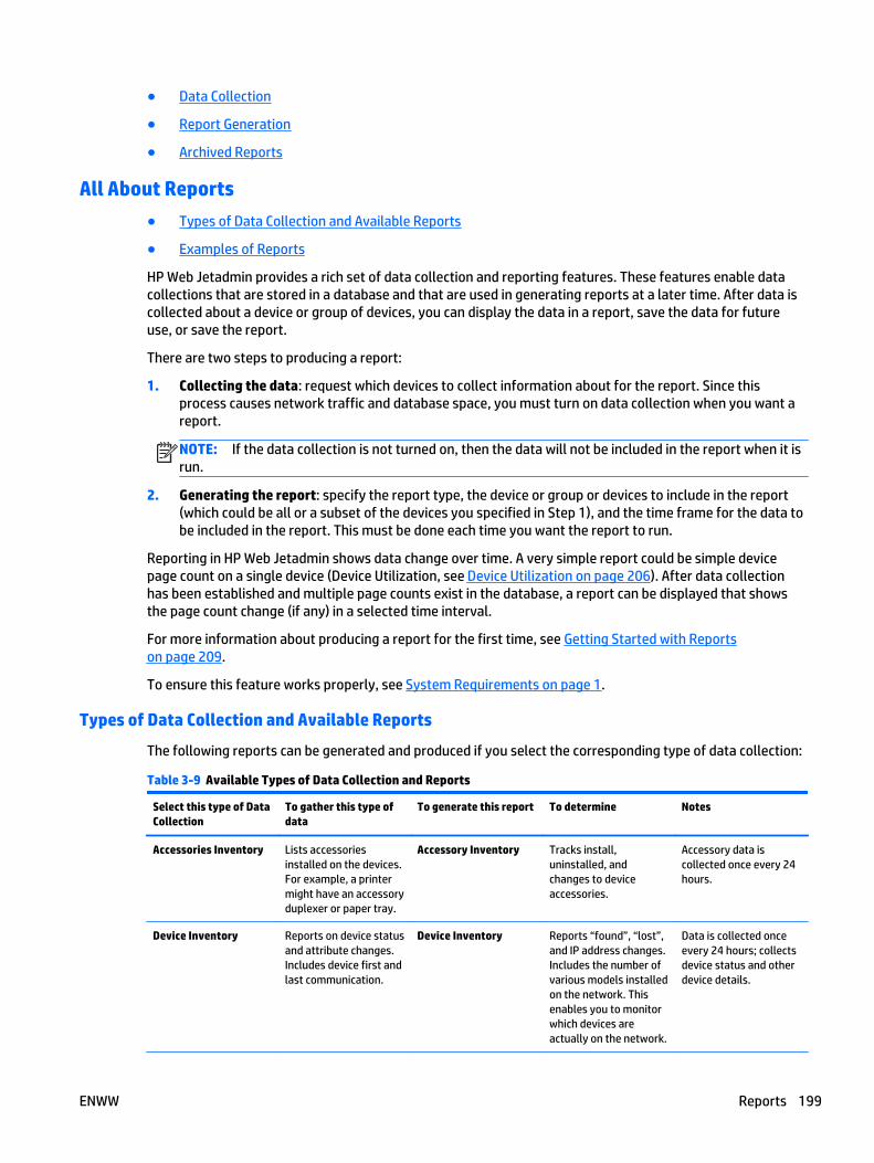
● Data Collection
● Report Generation
● Archived Reports
All About Reports
● Types of Data Collection and Available Reports
● Examples of Reports
HP Web Jetadmin provides a rich set of data collection and reporting features. These features enable datacollections that are stored in a database and that are used in generating reports at a later time. After data iscollected about a device or group of devices, you can display the data in a report, save the data for futureuse, or save the report.
There are two steps to producing a report:
1. Collecting the data: request which devices to collect information about for the report. Since thisprocess causes network traffic and database space, you must turn on data collection when you want areport.
NOTE: If the data collection is not turned on, then the data will not be included in the report when it isrun.
2. Generating the report: specify the report type, the device or group or devices to include in the report(which could be all or a subset of the devices you specified in Step 1), and the time frame for the data tobe included in the report. This must be done each time you want the report to run.
Reporting in HP Web Jetadmin shows data change over time. A very simple report could be simple devicepage count on a single device (Device Utilization, see Device Utilization on page 206). After data collectionhas been established and multiple page counts exist in the database, a report can be displayed that showsthe page count change (if any) in a selected time interval.
For more information about producing a report for the first time, see Getting Started with Reportson page 209.
To ensure this feature works properly, see System Requirements on page 1.
Types of Data Collection and Available Reports
The following reports can be generated and produced if you select the corresponding type of data collection:
Table 3-9 Available Types of Data Collection and Reports
Select this type of DataCollection
To gather this type ofdata
To generate this report To determine Notes
Accessories Inventory Lists accessoriesinstalled on the devices.For example, a printermight have an accessoryduplexer or paper tray.
Accessory Inventory Tracks install,uninstalled, andchanges to deviceaccessories.
Accessory data iscollected once every 24hours.
Device Inventory Reports on device statusand attribute changes.Includes device first andlast communication.
Device Inventory Reports “found”, “lost”,and IP address changes.Includes the number ofvarious models installedon the network. Thisenables you to monitorwhich devices areactually on the network.
Data is collected onceevery 24 hours; collectsdevice status and otherdevice details.
ENWW Reports 199
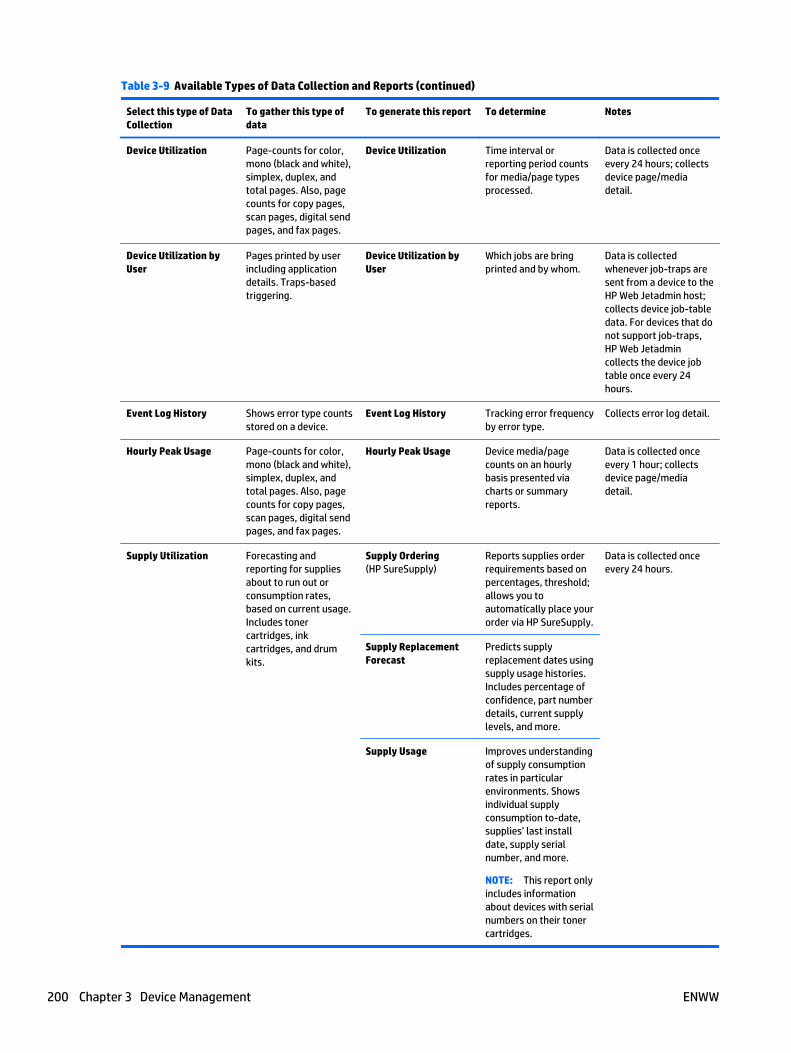
Table 3-9 Available Types of Data Collection and Reports (continued)
Select this type of DataCollection
To gather this type ofdata
To generate this report To determine Notes
Device Utilization Page-counts for color,mono (black and white),simplex, duplex, andtotal pages. Also, pagecounts for copy pages,scan pages, digital sendpages, and fax pages.
Device Utilization Time interval orreporting period countsfor media/page typesprocessed.
Data is collected onceevery 24 hours; collectsdevice page/mediadetail.
Device Utilization byUser
Pages printed by userincluding applicationdetails. Traps-basedtriggering.
Device Utilization byUser
Which jobs are bringprinted and by whom.
Data is collectedwhenever job-traps aresent from a device to theHP Web Jetadmin host;collects device job-tabledata. For devices that donot support job-traps,HP Web Jetadmincollects the device jobtable once every 24hours.
Event Log History Shows error type countsstored on a device.
Event Log History Tracking error frequencyby error type.
Collects error log detail.
Hourly Peak Usage Page-counts for color,mono (black and white),simplex, duplex, andtotal pages. Also, pagecounts for copy pages,scan pages, digital sendpages, and fax pages.
Hourly Peak Usage Device media/pagecounts on an hourlybasis presented viacharts or summaryreports.
Data is collected onceevery 1 hour; collectsdevice page/mediadetail.
Supply Utilization Forecasting andreporting for suppliesabout to run out orconsumption rates,based on current usage.Includes tonercartridges, inkcartridges, and drumkits.
Supply Ordering(HP SureSupply)
Reports supplies orderrequirements based onpercentages, threshold;allows you toautomatically place yourorder via HP SureSupply.
Data is collected onceevery 24 hours.
Supply ReplacementForecast
Predicts supplyreplacement dates usingsupply usage histories.Includes percentage ofconfidence, part numberdetails, current supplylevels, and more.
Supply Usage Improves understandingof supply consumptionrates in particularenvironments. Showsindividual supplyconsumption to-date,supplies’ last installdate, supply serialnumber, and more.
NOTE: This report onlyincludes informationabout devices with serialnumbers on their tonercartridges.
200 Chapter 3 Device Management ENWW
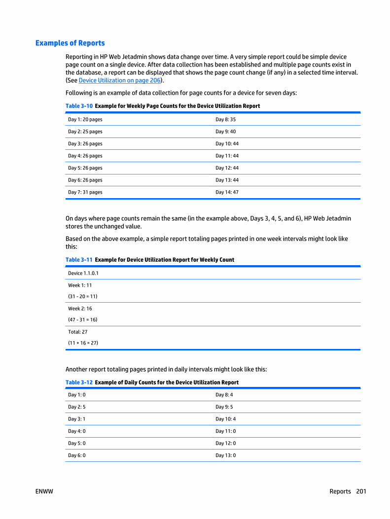
Examples of Reports
Reporting in HP Web Jetadmin shows data change over time. A very simple report could be simple devicepage count on a single device. After data collection has been established and multiple page counts exist inthe database, a report can be displayed that shows the page count change (if any) in a selected time interval.(See Device Utilization on page 206).
Following is an example of data collection for page counts for a device for seven days:
Table 3-10 Example for Weekly Page Counts for the Device Utilization Report
Day 1: 20 pages Day 8: 35
Day 2: 25 pages Day 9: 40
Day 3: 26 pages Day 10: 44
Day 4: 26 pages Day 11: 44
Day 5: 26 pages Day 12: 44
Day 6: 26 pages Day 13: 44
Day 7: 31 pages Day 14: 47
On days where page counts remain the same (in the example above, Days 3, 4, 5, and 6), HP Web Jetadminstores the unchanged value.
Based on the above example, a simple report totaling pages printed in one week intervals might look likethis:
Table 3-11 Example for Device Utilization Report for Weekly Count
Device 1.1.0.1
Week 1: 11
(31 - 20 = 11)
Week 2: 16
(47 - 31 = 16)
Total: 27
(11 + 16 = 27)
Another report totaling pages printed in daily intervals might look like this:
Table 3-12 Example of Daily Counts for the Device Utilization Report
Day 1: 0 Day 8: 4
Day 2: 5 Day 9: 5
Day 3: 1 Day 10: 4
Day 4: 0 Day 11: 0
Day 5: 0 Day 12: 0
Day 6: 0 Day 13: 0
ENWW Reports 201
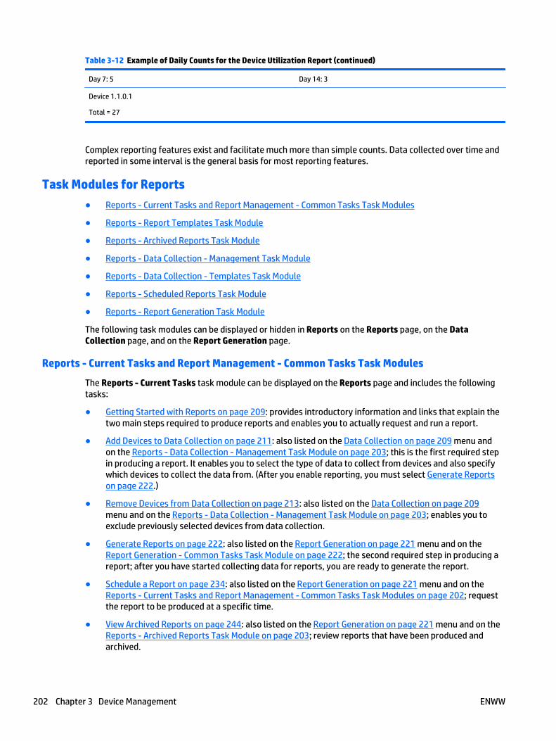
Table 3-12 Example of Daily Counts for the Device Utilization Report (continued)
Day 7: 5 Day 14: 3
Device 1.1.0.1
Total = 27
Complex reporting features exist and facilitate much more than simple counts. Data collected over time andreported in some interval is the general basis for most reporting features.
Task Modules for Reports
● Reports - Current Tasks and Report Management - Common Tasks Task Modules
● Reports - Report Templates Task Module
● Reports - Archived Reports Task Module
● Reports - Data Collection - Management Task Module
● Reports - Data Collection - Templates Task Module
● Reports - Scheduled Reports Task Module
● Reports - Report Generation Task Module
The following task modules can be displayed or hidden in Reports on the Reports page, on the DataCollection page, and on the Report Generation page.
Reports - Current Tasks and Report Management - Common Tasks Task Modules
The Reports - Current Tasks task module can be displayed on the Reports page and includes the followingtasks:
● Getting Started with Reports on page 209: provides introductory information and links that explain thetwo main steps required to produce reports and enables you to actually request and run a report.
● Add Devices to Data Collection on page 211: also listed on the Data Collection on page 209 menu andon the Reports - Data Collection - Management Task Module on page 203; this is the first required stepin producing a report. It enables you to select the type of data to collect from devices and also specifywhich devices to collect the data from. (After you enable reporting, you must select Generate Reportson page 222.)
● Remove Devices from Data Collection on page 213: also listed on the Data Collection on page 209menu and on the Reports - Data Collection - Management Task Module on page 203; enables you toexclude previously selected devices from data collection.
● Generate Reports on page 222: also listed on the Report Generation on page 221 menu and on theReport Generation - Common Tasks Task Module on page 222; the second required step in producing areport; after you have started collecting data for reports, you are ready to generate the report.
● Schedule a Report on page 234: also listed on the Report Generation on page 221 menu and on theReports - Current Tasks and Report Management - Common Tasks Task Modules on page 202; requestthe report to be produced at a specific time.
● View Archived Reports on page 244: also listed on the Report Generation on page 221 menu and on theReports - Archived Reports Task Module on page 203; review reports that have been produced andarchived.
202 Chapter 3 Device Management ENWW

The Reports - Current Tasks task module can be displayed in other areas of HP Web Jetadmin; in the otherareas it is Report Management - Common Tasks.
Reports - Report Templates Task Module
The Reports - Report Templates task module can be displayed on the Reports page and on the ReportGeneration page (Report Generation on page 221) and provides you access to the following tasks:
● Create (Create a Report Template on page 238): customize and store reports settings that can beapplied to one device or a group of devices while generating a report.
● Apply (Apply a Report Template on page 240): apply a report template that has already been createdto a device or group of devices.
● Edit (Edit a Report Template on page 241): make changes to a report template that has previouslybeen created.
● Delete (Delete a Report Template on page 242): delete a report template that has previously beencreated.
● Copy (Copy Template Wizard on page 85): copy a report template that has been previously created.
● View (Report Templates on page 238): view a report template that has been previously created.
Reports - Archived Reports Task Module
The Reports - Archived Reports task module can be displayed on the Reports page and on the ReportGeneration page (Report Generation on page 221) and provides you with access to the following tasks:
● View (View Archived Reports on page 244): also listed on the Report Generation on page 221 menu;review reports that have been produced and archived.
● Email (Email Reports on page 237): also listed on the Report Generation on page 221 menu; emailarchived reports.
● Save (Save Archived Reports on page 237): also listed on the Report Generation on page 221 menu;save reports that have been produced and archived.
● Delete (Delete Archived Reports on page 244): also listed on the Report Generation on page 221 menu;delete reports that have been produced and archived.
Reports - Data Collection - Management Task Module
The Reports - Data Collection - Management task module can be displayed on the Reports page and theData Collection page (Data Collection on page 209) and provides you with access to the following tasks:
● Add Devices (Add Devices to Data Collection on page 211): also listed on the Data Collectionon page 209 menu; add devices to a specific type of data collection.
● Remove Devices (Remove Devices from Data Collection on page 213): also listed on the Data Collectionon page 209 menu; remove devices from a specific type of data collection.
● View (Data Collection Summaries on page 217): also available from the left navigation pane as specificData Collection types; view the criteria selected for any specific type of data collection.
● Anomalies (Data Collection Anomalies on page 219): review data collection anomalies and choose toreconcile or resolve them. Anomalies are inconsistent information returned by the printer.
ENWW Reports 203
Reports - Data Collection - Templates Task Module
The Reports - Data Collection - Templates task module can be displayed on the Reports page and the DataCollection page (Data Collection on page 209) and provides you with access to the following tasks:
● Create (Create a Data Collection Template on page 213): also listed on the Data Collection on page 209menu; lets you create a template for data collection.
● Apply (Apply a Data Collection Template on page 214): also listed on the Data Collection on page 209menu; lets you apply a data collection template that has already been created to devices.
● Edit (Edit a Data Collection Template on page 215): also listed on the Data Collection on page 209menu; lets you edit a data collection template that has already been created.
● Delete (Delete a Data Collection Template on page 216) also listed on the Data Collection on page 209menu; lets you delete a data collection template that has already been created.
● Copy (Copy Template Wizard on page 85): copy a data collection template that has been previouslycreated.
● View (Data Collection Templates on page 216): also listed on the Data Collection on page 209 menu;lets you view a data collection template that has already been created.
Reports - Scheduled Reports Task Module
The Reports - Scheduled Reports task module can be displayed on the Reports page and on the ReportGeneration page (Report Generation on page 221) and provides you with access to the following tasks:
● Delete (Deleting Scheduled Reports on page 237): also listed on the Report Generation on page 221menu; lets you delete a report that has been scheduled (Schedule a Report on page 234).
● Edit (Editing the Schedule for a Report on page 237): also listed on the Report Generation on page 221menu; lets you edit a schedule for a report (Schedule a Report on page 234).
Reports - Report Generation Task Module
The Reports - Report Generation task module can be displayed on the Reports page and on the ReportGeneration page (Report Generation on page 221) and provides you with access to the following tasks:
● Generate: also listed on the Report Generation on page 221 menu and on the Report Generation -Common Tasks Task Module on page 222; the second required step in producing a report; after youhave started collecting data for reports, you are ready to generate the report (Generate Reportson page 222).
● Schedule: also listed on the Report Generation on page 221 menu and on the Reports - Current Tasksand Report Management - Common Tasks Task Modules on page 202; request the report to beproduced at a specific time (Schedule a Report on page 234).
● Sample: select a report and click Sample to display a sample of the report.
Related Application Options for Reports
Global settings can be stored here for managing report data.
● Manage the General Settings for Reports on page 68
● Configure the Data Collection Times for Reports on page 68
Available Reports
● Accessory Inventory
204 Chapter 3 Device Management ENWW
● Device Inventory
● Device Utilization
● Device Utilization by User
● Event Log History
● Hourly Peak Usage
● Supply Ordering
● Supply Replacement Forecast
● Supply Usage
Reports are generated through a combination of user-defined settings and collected data that is stored in thedatabase. There are many report types that correspond directly to data collection types. Completed reportscan be displayed through the HP Web Jetadmin client host. Reports are stored in an archive and can be sentto email through SMTP.
Reports can be generated in a summary format or in a reporting period format. Reports can be scheduled tooccur at a specified time automatically or immediately.
NOTE: If you schedule a task (for example, a discovery or a configuration or others) using a correspondingtemplate, the task uses the settings defined in the template at the time the task starts. This makes it easy toredefine settings used in a regularly scheduled task without having to delete and create a scheduled task.
NOTE: All schedules use the date and time on the server where HP Web Jetadmin is installed. The clientused to access HP Web Jetadmin might not be in the same time zone as the server where HP Web Jetadmin isinstalled. You should be aware of the potential for time and date differences when configuring schedules.
NOTE: Scheduled tasks are displayed in the Scheduled Tasks task module on the Device, Discovery,Configuration, Firmware, Reports, Storage, Solutions, and Application Management pages. You can alsodisplay any task module on the Overview page.
Accessory Inventory
The Accessory Inventory report can be used to inventory and track changes in device accessories.
Available report subtypes are:
● Time Interval: reports changes in accessories on devices over the specified time interval.
● Last Known Status: reports the last known status of each accessory on the device.
Available columns for this report include but are not limited to:
● Accessory Name
● Accessory Status
● Collection Date
For more information, see Types of Data Collection and Available Reports on page 199.
NOTE: You might need to power cycle your devices to reflect accessory changes.
Device Inventory
The Device Inventory report captures device status and device communication states. This report can beused to track devices that are missing or have been known to be missing in some time frame.
Available report subtypes are:
ENWW Reports 205

● Time Interval: reports changes in statuses on devices over the specified time interval.
● Last Known Status (Details): reports the last known status and communication state of each device.
● Last Known Status (Summary): categorizes devices into the different statuses.
Available columns for this report include but are not limited to:
● Inventory Status
● Inventory Date
For more information, see Types of Data Collection and Available Reports on page 199.
Device Utilization
The Device Utilization report tracks the media usage and page counts for a specific time period. The followingreport subtypes are available:
● Time Interval (Job Type): Displays the page counts for the specified job type (for example, mono, color,or copy jobs).
● Time Interval (Media Size): Displays the page counts for the specified media size.
● Job Type (Details): Displays the page counts for the specified job type and media sizes.
The report data that is available for job types includes, but is not limited to, the following:
● Total
● Total Accent Color
● Total Color
● Total Duplex
● Total General Office Color
● Total Mono
● Total Other Color
● Total Simplex
For more information, see Types of Data Collection and Available Reports on page 199.
Device Utilization by User
The Device Utilization by User reports by-user page counts based on job tables captured at the device.
Available report subtypes are:
● Time Interval: reports pages printed by user (application page count, color page counts, mono pagecounts, and others) over a time period.
● Time Interval (Media Size): reports pages printed by user of media sizes (letter, legal, and others) overa time period.
Available columns for this report include but are not limited to:
● Total
● MS Word
206 Chapter 3 Device Management ENWW
● Total Color
● Total Mono
For more information, see Types of Data Collection and Available Reports on page 199.
Event Log History
The Event Log History report shows device errors and error categories.
Available report subtypes are:
● Time Interval: reports pages printed on an hourly interval over a time period.
● Summary (Event Type): reports the number of events in each category for each device, by reportinterval (daily, weekly, monthly, and others).
Available columns for this report include but are not limited to:
● Event Code (Hex)
● Event Description
● Event Log Page Count
● Event Type
For more information, see Types of Data Collection and Available Reports on page 199.
Hourly Peak Usage
The Hourly Peak Usage report tracks hourly page and media counts.
Available report subtypes are:
● Time Interval: reports pages printed on an hourly interval over a time period.
Available columns for this report include but are not limited to:
● Total Mono
● Total
● Total Simplex
● Total Duplex
● Total Simplex
For more information, see Types of Data Collection and Available Reports on page 199.
Supply Ordering
The Supply Ordering report provides a list of needed supplies based on your specified percentage andthreshold. Also included is an HP SureSupply order option.
Available report subtypes are:
● Details: shows how many supplies per device are needed based on the specified threshold.
● Summary: shows a consolidated list of totals needed per supply part number across all devices basedon the specified threshold.
Available columns for this report include but are not limited to:
ENWW Reports 207
● Supply
● Supply Part Number
● Installation Date
● Estimated Supply Level (%)
For more information, see Types of Data Collection and Available Reports on page 199.
Supply Replacement Forecast
The Supply Replacement Forecast report is a predictive report showing replacement needs for specificsupplies. The device supplies metrics that exist in your database will be analyzed, a prediction about neededsupplies will be made, and the Supply Replacement Forecast will be generated. This prediction is based ondetails that include supplies levels, percentage coverage, and other historic data relegated to supplies andprinting. The report will include a percentage confidence rating to give you an indication of how much dataexisted and was used in the analysis. If very little data existed, the percentage confidence should indicate alow value. If you have been tracking supplies on devices for a long period of time, the report would show ahigher percentage of confidence.
Available report subtypes are:
● Details: shows estimated forecasted replacement date per device per supply as well as quantity ofsupply needed in the specified time period.
● Summary: shows the quantity of supply needed by part number across all devices based on specifiedtime period.
Available columns for this report include but are not limited to:
● Supply
● Supply Part Number
● Estimated Remaining
For more information, see Types of Data Collection and Available Reports on page 199.
Supply Usage
The Supply Usage report shows usage based on page count over supply lifetime, including many supplydetails including install dates and serial numbers. This report only includes information about devices withserial numbers on their toner cartridges.
Available report subtypes are:
● Details: shows supplies that are installed (active) and/or uninstalled (removed) on the device andprovides usage information (installation date, estimated percentage remaining, and more).
● Inventory: tracks a specific supply instance between devices (the supply must have a valid serialnumber).
Available columns for this report include but are not limited to:
● Supply Part Number
● Supply Status
● Supply Installation Date
● Average Supply Coverage (%)
● Average Supply Coverage (%) (default)
208 Chapter 3 Device Management ENWW
For more information, see Types of Data Collection and Available Reports on page 199.
Getting Started with Reports
The following steps are required to generate a report:
1. Collect the data: Specify the devices for which HP Web Jetadmin collects data. The data collectionprocess causes network traffic and requires database space, so you must enable data collection whenyou want a report. You can specify which reports HP Web Jetadmin generates based on the type of datacollection you select.
2. Generate the report: Specify the following options:
● The type of report to generate. The type of data collection specified in step 1 determines whichreports HP Web Jetadmin can generate.
● The device group or individual devices to include in the report, which might be all of the devices ora subset of the devices specified in step 1.
NOTE: You can only select devices for which data has been collected.
● The time frame for the data to be included in the report.
This must be done each time you want the report to run.
Data Collection
● Data Collection Cycle
● Initial Data Collection
● Device Utilization by User and Data Collections
● Using Group Policies to Set Data Collection
● Data Collection - Common Tasks Task Module
● Add Devices to Data Collection
● Remove Devices from Data Collection
● Create a Data Collection Template
● Apply a Data Collection Template
● Edit a Data Collection Template
● Delete a Data Collection Template
● Copy a Data Collection Template
● Data Collection Templates
● Data Collection Summaries
● Data Collection Statuses
● Data Collection Anomalies
Data collections are groups of devices that have specific collection types enabled. You can apply a datacollection type such as Device Utilization to a single device, to multiple devices, or to a device group. When adata collection is first applied to a device or devices, HP Web Jetadmin launches a data collectionimmediately establishing a data baseline. Once the device is populated under a specific data collection type,data collections occur at some interval or by way of some trigger.
ENWW Reports 209
NOTE: Applying data collection to a device group is done through Group Policies on page 112.
As data is collected, it is stored in tables within the HP Web Jetadmin database. Data retention is set to oneyear beyond the initial collection date. This value can be changed in Tools > Options > Shared > ServerMaintenance > Reports (Manage the Report Data on page 44). Data collections for Reports can be retainedfor up to 5 years.
Data Collection Cycle
Data collection types all have a specific collection cycle that may or may not be dependent on a schedule. TheDevice Utilization by User data collections are triggered when printers send job-trap packets into theHP Web Jetadmin host. All other types are schedule-triggered. All data collections collect data every 24 hoursexcept for the Hourly Peak Usage data collection which is collected once every hour to provide greaterreporting resolution.
The default start time for the data collection 24 hour cycle is set at 12:00AM at the HP Web Jetadmin host.This can be configured for each data collection in Tools > Options > Device Management > Reports > DataCollection Times. When subscribing a device to a data collection, you can choose the time of collection if youprefer a different time. The 24 hour cycle is designed to ensure reporting accuracy. Data within reports will bemarked if the data collected did not represent a full 24 hour cycle.
Initial Data Collection
Activating data collection always launches the specific data collection type on selected devices. This is doneto gather initial or baseline data that is then stored in the database. This is not a user-selectable action. Theresult of this initial data collection can be observed in the Results display for any completed data collection.
Device Utilization by User and Data Collections
The Device Utilization by User data collection type uses SNMP traps to trigger the HP Web Jetadmin hostdata collection. Every time a print job is completed by the device, a trap is sent and HP Web Jetadmin runs acomplete query of the device’s job table. Any new entries in the job table are stored in the HP Web Jetadmindatabase; all old entries that were previously stored are discarded.
Device Utilization by User accuracy may be limited by two things:
● the device’s ability to store only a limited number of jobs in the job table.
● the device’s ability to trap when multiple print jobs are queued.
Both of these are dependant on device printer model and firmware. Device Utilization by User and Reportingshould never be used as a substitute for job accounting. HP Web Jetadmin Reports features are designed fortrending and analysis purposes.
NOTE: For devices that don’t support job-traps, HP Web Jetadmin will collect the device’s job table onceevery 24 hours.
Reports and Alerts Traps Listener Port
HP Web Jetadmin uses UDP port 27892 as the traps listener port for alerts and any reports that are based onby-user collections.
Device and Printer Driver Support for Device Utilization by User
Job logging features are not available on all HP printers. Check your printer documentation to be sure thesedevice-based features exist.
210 Chapter 3 Device Management ENWW

End of job trapping is not supported on all HP printers. In the case where end of job trapping is not supported,HP Web Jetadmin will query the job tables once per collection period (24 hours). This may impact theaccuracy of by-user reporting due to the limited size of the device job log.
Windows print drivers supplied by HP are known to support device job log entries. Windows print driversavailable through Microsoft Windows operating systems may not support job log entries. Be sure to useHP model-specific drivers or the HP Universal Print Driver (UPD) when by-user tracking is required.
Using Group Policies to Set Data Collection
The Group Policies feature is a powerful new automation tool that can save you a lot of time configuringdevices and HP Web Jetadmin settings. Any device group has a property known as a Group Policies. Onepolicy that can be added to any device group’s properties is Enable Data Collection. When activating theEnable Data Collection to a device group, you must define a data collection template from the list of existingtemplates. Also, a trigger is specified that enables the configuration to take place either as the device ispopulated into the group or as the device is de-populated from the group. Multiple Enable Data Collectionsettings can exist on a single device group. See Group Policies on page 112.
Data Collection - Common Tasks Task Module
Tasks available within Data Collection are listed in the Data Collection - Common Tasks task module:
● Add Devices to Data Collection on page 211: also listed on the Reports - Data Collection - ManagementTask Module on page 203; lets you add devices to a specific type of data collection.
● Remove Devices from Data Collection on page 213: also listed on the Reports - Data Collection -Management Task Module on page 203; lets you remove devices from a specific type of data collection.
● Create a Data Collection Template on page 213: also listed on the Reports - Data Collection - TemplatesTask Module on page 204 menu; lets you create a template for data collection.
● Apply a Data Collection Template on page 214: also listed on the Reports - Data Collection - TemplatesTask Module on page 204 menu; lets you apply a data collection template that has already been createdto devices.
● Edit a Data Collection Template on page 215: also listed on the Reports - Data Collection - TemplatesTask Module on page 204 menu; lets you edit a data collection template that has already been created.
● Delete a Data Collection Template on page 216: also listed on the Reports - Data Collection - TemplatesTask Module on page 204 menu; lets you delete a data collection template that has already beencreated.
● Copy Template Wizard on page 85: copy a data collection template that has been previously created.
Add Devices to Data Collection
● Data Collection Custom Collection Time
● Steps for Adding Devices to Data Collection
● Other Ways to Add Devices to Data Collection
Devices can be added to any type of data collection.
Data Collection Custom Collection Time
HP Web Jetadmin has a custom collection time feature that allows you to specify the time zone of the devicesyou are collecting for and the hour to perform the collection. The data collection start time is 12:00AM localserver time. The default collection time for the Web Jetadmin server can be altered through Tools >Options > Device Management > Reports > Data Collection Times (see Configure the Data Collection Times
ENWW Reports 211
for Reports on page 68). You can specify the time zone and custom hour when setting up data collection (seeAdd Devices to Data Collection on page 211) or when creating data collection templates (Create a DataCollection Template on page 213), For example:
Joy has devices in the Pacific time zone. Her HP Web Jetadmin server is in the mountain time zone. Thedevices that Joy manages are not turned on until 8AM. Pacific time. Data collection at 12AM Mountain timewould not capture any data for the devices since they are turned off at the end of the business day. When Joysets up data collection for the devices, Joy can specify that she would like the collection to run in the Pacifictime zone and at 9:00AM. The data collection would start on the HP Web Jetadmin server at 10AM Mountaintime which is 9AM Pacific time.
HP Web Jetadmin will continue to use a 24 hour data collection cycle for all devices.
Steps for Adding Devices to Data Collection
NOTE: If you access this feature through the Reports - Data Collection - Management Task Moduleon page 203, then you will skip the first page of the Add Devices to Data Collection Wizard.
1. Expand the Reports tree in the left navigation pane and then click Data Collection.
In the Data Collection - Common Tasks task module, select Add devices to data collection. The AddDevices to Data Collection wizard is started with the Select data collection page displayed.
2. Select the template to use, if any and then select the type of data collection(s) to perform.
3. Select the time zone and the time to start data collection. The click Next; the Select devices page isdisplayed.
NOTE: For more information about Data Collection offset hours, see Data Collection Custom CollectionTime on page 211.
4. Select the device by highlighting it and clicking the arrow buttons between the two lists. To selectmultiple devices, use either Ctrl+Click or Shift+Click. To move all devices from one list to the other, usethe double arrow buttons. You can sort the list of available devices by clicking the column headers, orview more columns by right-clicking the column headers.
You can also select an entire group instead of individual devices, by changing the selection method toGroups. Tasks (for example configurations and more) can be performed on a single group or a groupand all of its subgroups.
NOTE: Including all subgroups can potentially take much longer and cause much more network traffic,so it should be used only when appropriate.
If you schedule a task using a group, the task will apply to the devices in the group at the time the taskstarts. This makes it easy to redefine the devices used in regularly scheduled tasks without having todelete and create a scheduled task.
NOTE: The columns displayed on the Select devices page are defined in View > Preferences > DeviceIdentification.
5. Click Next. The Confirm page is displayed.
6. Click Add Devices. The Results page is displayed.
Click Details to view the types of data collection for that device. When done, click Close; the Resultspage is displayed again.
7. Click Done to display the Data Collection page.
8. Now you are ready to generate a report.
212 Chapter 3 Device Management ENWW
Other Ways to Add Devices to Data Collection
● In the left navigation pane, right-click on Reports and select Add devices to data collection.
● In the All Devices list, highlight the device and right-click Reports and select Add to data collection.
● In the All Devices list, highlight the device and then in the lower portion of the page click the Reportstab. Then click Add devices to data collection.
Remove Devices from Data Collection
● Steps for Removing Devices from Data Collection
● Other Ways to Remove Devices from Data Collection
You can remove devices from any type of data collection at any time.
Steps for Removing Devices from Data Collection
1. Expand the Reports tree in the left navigation pane and then click Data Collection.
In the Data Collection - Common Tasks task module, select Remove devices from data collection. TheRemove Devices from Data Collection wizard is started with the Select data collection type pagedisplayed.
2. Select the type of data collection that you want to remove devices from and click Next. The Selectdevices page is displayed.
3. Select the device by highlighting it and clicking the arrow buttons between the two lists. To selectmultiple devices, use either Ctrl+Click or Shift+Click. To move all devices from one list to the other, usethe double arrow buttons. You can sort the list of available devices by clicking the column headers, orview more columns by right-clicking the column headers.
NOTE: The columns displayed on the Select devices page are defined in View > Preferences > DeviceIdentification.
4. Click Next. The Confirm page is displayed showing you the devices to be deleted from this type of datacollection.
5. Click Next. The Results page is displayed.
6. Click Done to display the Data Collection page.
Other Ways to Remove Devices from Data Collection
● In the left navigation pane, right-click on Reports and select Remove devices from data collection.
Create a Data Collection Template
● Steps for Creating a Data Collection Template
● Other Ways to Create a Data Collection Template
For more information, see Types of Data Collection and Available Reports on page 199.
Data Collection Templates are designed to help you enable more than one data collection type. In summary,you can create a data collection template by opening the Create Data Collection Template wizard, select oneor more data collection types, name the template, and then confirm the settings.
After the template has been created, it can be applied to devices in the same ways as individual datacollection types. By applying data collection templates, you are actually configuring the individual datacollection types without having to activate controls multiple times.
ENWW Reports 213

For scheduling information, see Data Collection Custom Collection Time on page 211.
Steps for Creating a Data Collection Template
1. Expand the Reports tree in the left navigation pane and then click Data Collection.
In the Data Collection - Common Tasks task module, select Create data collection template. TheCreate Data Collection Template wizard is started with the Choose data collection type pagedisplayed.
2. Select the type of data collection for this template and specify the time zone and collection time andthen click Next. The Select collection time page is displayed.
3. Select the time zone and the time to start data collection. The click Next; the Specify name page isdisplayed.
NOTE: For more information about Data Collection offset hours, see Data Collection Custom CollectionTime on page 211.
4. Type the name for the template and then click Next. The Confirm page is displayed.
5. Click Next. The Results page is displayed.
6. Click Done to display the Data Collection page.
7. Now you are ready to apply the template to devices and to generate a report.
Other Ways to Create a Data Collection Template
● In the left navigation pane, right-click on Reports and select Create data collection template.
Apply a Data Collection Template
● Steps for Applying a Data Collection Template
● Other Ways to Apply a Data Collection Template
You can apply a Data Collection template that has already been created to a device or group of devices. Youcan also turn data collection on and off; this is useful if you need to control the network traffic generated tocommunicate with the devices and also because the data is stored in database tables which, over time, canbecome quite large. By selecting the data to include, you have great flexibility as to what you want to includein your reports.
Steps for Applying a Data Collection Template
1. Expand the Reports tree in the left navigation pane and then click Data Collection.
In the Data Collection - Common Tasks task module, select Apply data collection template. The ApplyData Collection Template wizard is started with the Select data collection page displayed.
2. Select a template and click Next. The Select devices page is displayed.
3. Select the device by highlighting it and clicking the arrow buttons between the two lists. To selectmultiple devices, use either Ctrl+Click or Shift+Click. To move all devices from one list to the other, usethe double arrow buttons. You can sort the list of available devices by clicking the column headers, orview more columns by right-clicking the column headers.
You can also select an entire group instead of individual devices, by changing the selection method toGroups. Tasks (for example configurations and more) can be performed on a single group or a groupand all of its subgroups.
214 Chapter 3 Device Management ENWW
NOTE: Including all subgroups can potentially take much longer and cause much more network traffic,so it should be used only when appropriate.
If you schedule a task using a group, the task will apply to the devices in the group at the time the taskstarts. This makes it easy to redefine the devices used in regularly scheduled tasks without having todelete and create a scheduled task.
NOTE: The columns displayed on the Select devices page are defined in View > Preferences > DeviceIdentification.
4. Click Next. The Confirm page is displayed.
5. Click Next. The Results page is displayed.
Click Details to view the types of data collection for that device. To expand the details for all devices,click Expand All. When done, click Close; the Results page is displayed again.
6. Click Done to display the Data Collection page.
7. Now you are ready to generate a report.
Other Ways to Apply a Data Collection Template
● In the left navigation pane, right-click on Reports and select Apply data collection template.
● In the All Devices list, right-click Reports and select Apply data collection template.
● In the All Devices list, highlight the device and then in the lower portion of the page click the Reportstab. Then click Apply data collection template.
Edit a Data Collection Template
● Steps for Editing a Data Collection Template
● Other Ways to Edit a Data Collection Template
You can change the type of data collection for a specified template and you can change the template’s name.
Steps for Editing a Data Collection Template
1. Expand the Reports tree in the left navigation pane and then click Data Collection.
In the Data Collection - Common Tasks task module, select Edit data collection template. The EditData Collection Template wizard is started with the Select template page displayed.
2. Select a template and click Next. The Choose data collection type page is displayed.
3. To change the type of data collection for this template, check the type or types to include and uncheckthose that should not be included. Then click Next. The Select collection time page is displayed.
4. Select the time zone and the time to start data collection. The click Next; the Specify name page isdisplayed.
NOTE: For more information about Data Collection offset hours, see Data Collection Custom CollectionTime on page 211.
5. To change the name for this template, type the new name in Template name (or you can leave thename as it was). Then click Next. The Confirm page is displayed showing you the old settings and thenew settings for this template.
6. Click Next. The Results page is displayed.
ENWW Reports 215
7. Click Done to display the Data Collection page.
8. Now you are ready to generate a report.
Other Ways to Edit a Data Collection Template
● In the left navigation pane, right-click on Reports and select Edit data collection template.
Delete a Data Collection Template
● Steps for Deleting a Data Collection Template
● Other Ways to Delete a Data Collection Template
You can delete a data collection template.
Steps for Deleting a Data Collection Template
1. Expand the Reports tree in the left navigation pane and then click Data Collection.
In the Data Collection - Common Tasks task module, select Delete data collection template. TheDelete Data Collection Templates wizard is started with the Select templates page displayed.
2. Select the data collection template or templates to delete and click Next. The Confirm page isdisplayed.
3. Click Next. The Results page is displayed.
4. Click Done to display the Data Collection page.
Other Ways to Delete a Data Collection Template
● In the left navigation pane, right-click on Reports and select Delete data collection template.
Copy a Data Collection Template
Throughout Device Management view, templates can be created and managed to save you time and provideconsistency. Templates contain configuration preferences (that vary by template type) and can be applied todevices or groups. Templates are available in Configuration, Alerts, Discovery, Data Collection, and ReportGeneration. For more information, see Copy Template Wizard on page 85.
Data Collection Templates
● Steps for Accessing and Working with Data Collection Templates
● Other Ways to Access a Data Collection Template
In Data Collection Templates, you can:
● Create new templates (Create a Data Collection Template on page 213).
● View existing templates (Data Collection Templates on page 216).
● Edit existing templates (Edit a Data Collection Template on page 215).
● Apply existing templates (Apply a Data Collection Template on page 214).
● Delete existing templates (Delete a Data Collection Template on page 216).
● Copy existing templates (Copy Template Wizard on page 85).
You can also add devices to or remove devices from this type of data collection.
216 Chapter 3 Device Management ENWW
Steps for Accessing and Working with Data Collection Templates
1. Expand the Reports tree in the left navigation pane; then expand the Data Collection tree and clickTemplates.
2. Do one of the following:
● To create a data collection template, click New (Create a Data Collection Template on page 213).
● To apply an existing data collection template, click Apply (Apply a Data Collection Templateon page 214).
● To edit an existing data collection template, highlight the template and click Edit (Edit a DataCollection Template on page 215).
● To delete an existing data collection template, click Delete (Delete a Data Collection Templateon page 216).
● To copy a data collection template that has been previously created, click Copy (Copy TemplateWizard on page 85).
● To view an existing data collection template, highlight the template and click View. Then you canedit, apply, or delete the template (see below).
Other Ways to Access a Data Collection Template
● In the left navigation pane, expand Reports and then expand Data Collection. All of the existingtemplates are listed in the Data Collection - Templates task module.
Data Collection Summaries
● Steps for Data Collection Summaries
● Other Ways for Data Collection Summaries
You can view which devices have been added to any type of data collection. The following information isdisplayed:
● Name: name of the data collection.
● Traffic impact: how this data collection, while running, affects network traffic (high, medium, or low).
● Collection time: how often this data collection is run.
● # Devices: how many devices are included in this data collection. (More devices included mightnegatively impact network traffic).
● Reports supported: shows all of the reports you could generate with this particular type of datacollection.
From this page, you can perform the following tasks. For steps to perform these tasks, see Steps for DataCollection Summaries on page 218.
● Collect Now: run this data collection now.
● Add Devices add devices to this type of data collection.
● Remove Devices: remove the selected devices from this type of data collection.
● Generate Report: generate a report on the selected devices using this data collection.
ENWW Reports 217
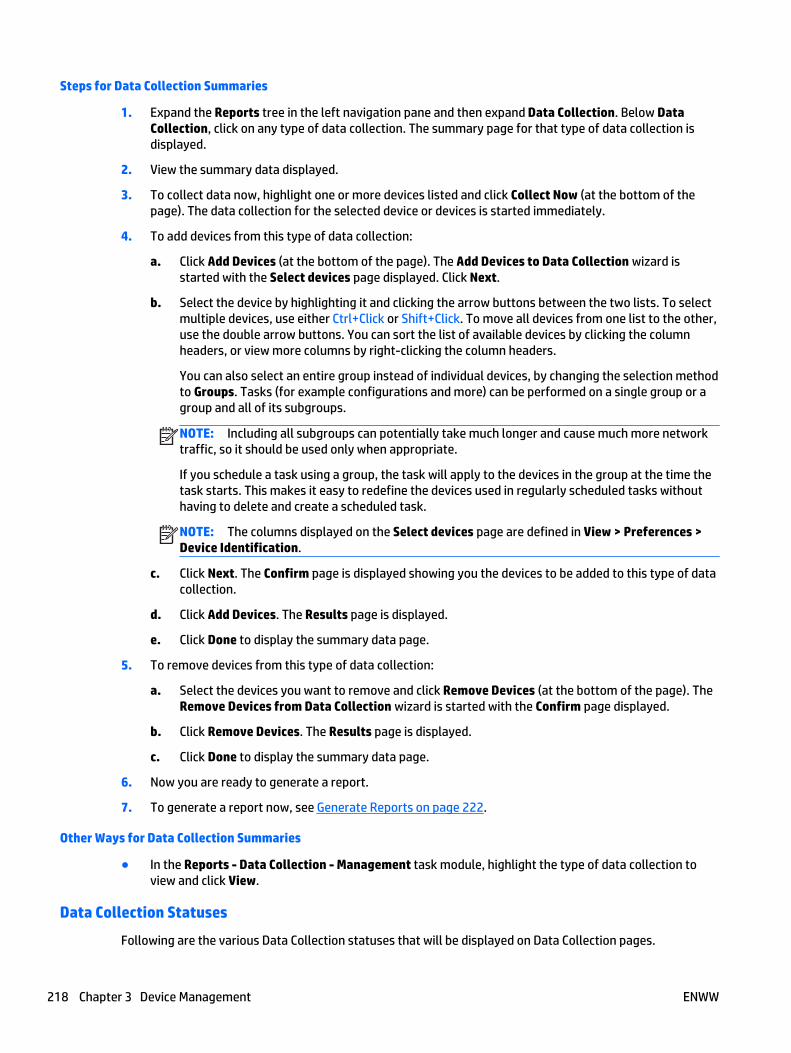
Steps for Data Collection Summaries
1. Expand the Reports tree in the left navigation pane and then expand Data Collection. Below DataCollection, click on any type of data collection. The summary page for that type of data collection isdisplayed.
2. View the summary data displayed.
3. To collect data now, highlight one or more devices listed and click Collect Now (at the bottom of thepage). The data collection for the selected device or devices is started immediately.
4. To add devices from this type of data collection:
a. Click Add Devices (at the bottom of the page). The Add Devices to Data Collection wizard isstarted with the Select devices page displayed. Click Next.
b. Select the device by highlighting it and clicking the arrow buttons between the two lists. To selectmultiple devices, use either Ctrl+Click or Shift+Click. To move all devices from one list to the other,use the double arrow buttons. You can sort the list of available devices by clicking the columnheaders, or view more columns by right-clicking the column headers.
You can also select an entire group instead of individual devices, by changing the selection methodto Groups. Tasks (for example configurations and more) can be performed on a single group or agroup and all of its subgroups.
NOTE: Including all subgroups can potentially take much longer and cause much more networktraffic, so it should be used only when appropriate.
If you schedule a task using a group, the task will apply to the devices in the group at the time thetask starts. This makes it easy to redefine the devices used in regularly scheduled tasks withouthaving to delete and create a scheduled task.
NOTE: The columns displayed on the Select devices page are defined in View > Preferences >Device Identification.
c. Click Next. The Confirm page is displayed showing you the devices to be added to this type of datacollection.
d. Click Add Devices. The Results page is displayed.
e. Click Done to display the summary data page.
5. To remove devices from this type of data collection:
a. Select the devices you want to remove and click Remove Devices (at the bottom of the page). TheRemove Devices from Data Collection wizard is started with the Confirm page displayed.
b. Click Remove Devices. The Results page is displayed.
c. Click Done to display the summary data page.
6. Now you are ready to generate a report.
7. To generate a report now, see Generate Reports on page 222.
Other Ways for Data Collection Summaries
● In the Reports - Data Collection - Management task module, highlight the type of data collection toview and click View.
Data Collection Statuses
Following are the various Data Collection statuses that will be displayed on Data Collection pages.
218 Chapter 3 Device Management ENWW
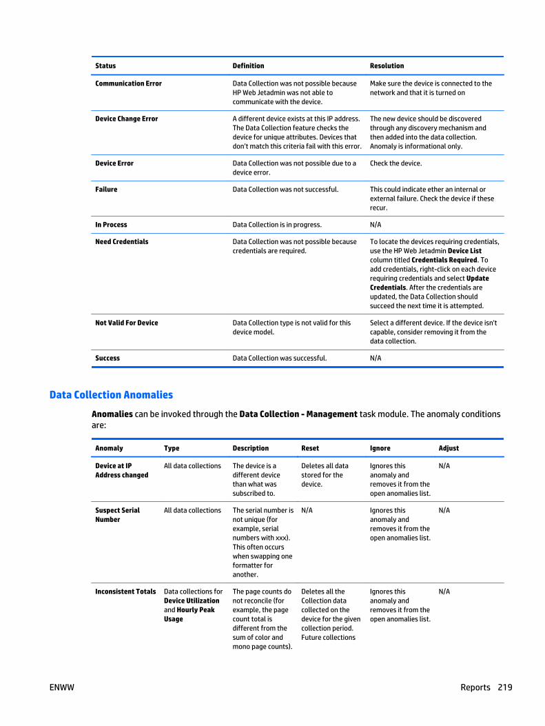
Status Definition Resolution
Communication Error Data Collection was not possible becauseHP Web Jetadmin was not able tocommunicate with the device.
Make sure the device is connected to thenetwork and that it is turned on
Device Change Error A different device exists at this IP address.The Data Collection feature checks thedevice for unique attributes. Devices thatdon’t match this criteria fail with this error.
The new device should be discoveredthrough any discovery mechanism andthen added into the data collection.Anomaly is informational only.
Device Error Data Collection was not possible due to adevice error.
Check the device.
Failure Data Collection was not successful. This could indicate ether an internal orexternal failure. Check the device if theserecur.
In Process Data Collection is in progress. N/A
Need Credentials Data Collection was not possible becausecredentials are required.
To locate the devices requiring credentials,use the HP Web Jetadmin Device Listcolumn titled Credentials Required. Toadd credentials, right-click on each devicerequiring credentials and select UpdateCredentials. After the credentials areupdated, the Data Collection shouldsucceed the next time it is attempted.
Not Valid For Device Data Collection type is not valid for thisdevice model.
Select a different device. If the device isn'tcapable, consider removing it from thedata collection.
Success Data Collection was successful. N/A
Data Collection Anomalies
Anomalies can be invoked through the Data Collection - Management task module. The anomaly conditionsare:
Anomaly Type Description Reset Ignore Adjust
Device at IPAddress changed
All data collections The device is adifferent devicethan what wassubscribed to.
Deletes all datastored for thedevice.
Ignores thisanomaly andremoves it from theopen anomalies list.
N/A
Suspect SerialNumber
All data collections The serial number isnot unique (forexample, serialnumbers with xxx).This often occurswhen swapping oneformatter foranother.
N/A Ignores thisanomaly andremoves it from theopen anomalies list.
N/A
Inconsistent Totals Data collections forDevice Utilizationand Hourly PeakUsage
The page counts donot reconcile (forexample, the pagecount total isdifferent from thesum of color andmono page counts).
Deletes all theCollection datacollected on thedevice for the givencollection period.Future collections
Ignores thisanomaly andremoves it from theopen anomalies list.
N/A
ENWW Reports 219
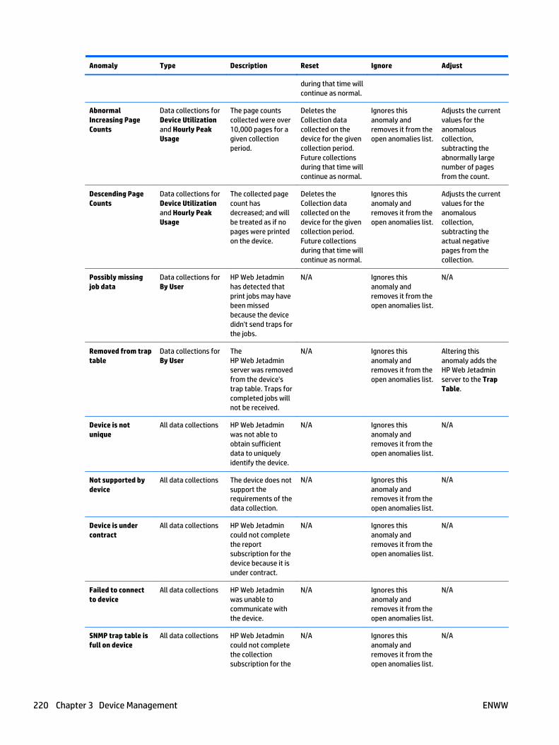
Anomaly Type Description Reset Ignore Adjust
during that time willcontinue as normal.
AbnormalIncreasing PageCounts
Data collections forDevice Utilizationand Hourly PeakUsage
The page countscollected were over10,000 pages for agiven collectionperiod.
Deletes theCollection datacollected on thedevice for the givencollection period.Future collectionsduring that time willcontinue as normal.
Ignores thisanomaly andremoves it from theopen anomalies list.
Adjusts the currentvalues for theanomalouscollection,subtracting theabnormally largenumber of pagesfrom the count.
Descending PageCounts
Data collections forDevice Utilizationand Hourly PeakUsage
The collected pagecount hasdecreased; and willbe treated as if nopages were printedon the device.
Deletes theCollection datacollected on thedevice for the givencollection period.Future collectionsduring that time willcontinue as normal.
Ignores thisanomaly andremoves it from theopen anomalies list.
Adjusts the currentvalues for theanomalouscollection,subtracting theactual negativepages from thecollection.
Possibly missingjob data
Data collections forBy User
HP Web Jetadminhas detected thatprint jobs may havebeen missedbecause the devicedidn't send traps forthe jobs.
N/A Ignores thisanomaly andremoves it from theopen anomalies list.
N/A
Removed from traptable
Data collections forBy User
TheHP Web Jetadminserver was removedfrom the device'strap table. Traps forcompleted jobs willnot be received.
N/A Ignores thisanomaly andremoves it from theopen anomalies list.
Altering thisanomaly adds theHP Web Jetadminserver to the TrapTable.
Device is notunique
All data collections HP Web Jetadminwas not able toobtain sufficientdata to uniquelyidentify the device.
N/A Ignores thisanomaly andremoves it from theopen anomalies list.
N/A
Not supported bydevice
All data collections The device does notsupport therequirements of thedata collection.
N/A Ignores thisanomaly andremoves it from theopen anomalies list.
N/A
Device is undercontract
All data collections HP Web Jetadmincould not completethe reportsubscription for thedevice because it isunder contract.
N/A Ignores thisanomaly andremoves it from theopen anomalies list.
N/A
Failed to connectto device
All data collections HP Web Jetadminwas unable tocommunicate withthe device.
N/A Ignores thisanomaly andremoves it from theopen anomalies list.
N/A
SNMP trap table isfull on device
All data collections HP Web Jetadmincould not completethe collectionsubscription for the
N/A Ignores thisanomaly andremoves it from theopen anomalies list.
N/A
220 Chapter 3 Device Management ENWW
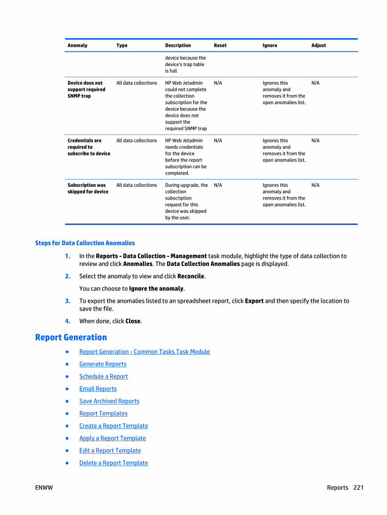
Anomaly Type Description Reset Ignore Adjust
device because thedevice's trap tableis full
Device does notsupport requiredSNMP trap
All data collections HP Web Jetadmincould not completethe collectionsubscription for thedevice because thedevice does notsupport therequired SNMP trap
N/A Ignores thisanomaly andremoves it from theopen anomalies list.
N/A
Credentials arerequired tosubscribe to device
All data collections HP Web Jetadminneeds credentialsfor the devicebefore the reportsubscription can becompleted.
N/A Ignores thisanomaly andremoves it from theopen anomalies list.
N/A
Subscription wasskipped for device
All data collections During upgrade, thecollectionsubscriptionrequest for thisdevice was skippedby the user.
N/A Ignores thisanomaly andremoves it from theopen anomalies list.
N/A
Steps for Data Collection Anomalies
1. In the Reports - Data Collection - Management task module, highlight the type of data collection toreview and click Anomalies. The Data Collection Anomalies page is displayed.
2. Select the anomaly to view and click Reconcile.
You can choose to Ignore the anomaly.
3. To export the anomalies listed to an spreadsheet report, click Export and then specify the location tosave the file.
4. When done, click Close.
Report Generation
● Report Generation - Common Tasks Task Module
● Generate Reports
● Schedule a Report
● Email Reports
● Save Archived Reports
● Report Templates
● Create a Report Template
● Apply a Report Template
● Edit a Report Template
● Delete a Report Template
ENWW Reports 221
● Copy a Report Template
● View Reports
After data collection has been performed, you can generate reports. The type of reports that can begenerated is dependent upon the type of data collection that you ran.
Report Generation - Common Tasks Task Module
Tasks available within Report Generation are listed in the Report Generation - Common Tasks task module:
● Generate Reports on page 222
● Schedule a Report on page 234
● Create a Report Template on page 238
● Apply a Report Template on page 240
● Edit a Report Template on page 241
● Delete a Report Template on page 242
● Copy Template Wizard on page 85
● View Archived Reports on page 244
● Email Reports on page 237
● Save Archived Reports on page 237
● Delete Archived Reports on page 244
Generate Reports
● Accessory Inventory Report Settings
● Device Inventory Report Settings
● Device Utilization Report Settings
● Device Utilization by User Report Settings
● Event Log History Report Settings
● Hourly Peak Usage Report Settings
● Supply Ordering Report Settings
● Supply Replacement Forecast Report Settings
● Supply Usage Report Settings
Before you can generate a report, you must specify the report type, devices or device groups included in thereport, device information included in the report, time period for the report, and if the report is archived orsent to an email address. You can generate the report immediately or schedule the report to run on arecurring basis.
You can select the device information that is included in the report from the Available columns list in theGenerate Report wizard. Because there are so many columns available, the list provides three categories ofcolumns—Favorites, All, and Obsolete. Each category contains a list of columns and additional categoriesthat you can select.
222 Chapter 3 Device Management ENWW

Steps to Generate a Report
1. In the Device Management navigation pane, right-click Reports, and then select Generate report. TheGenerate Report wizard starts.
2. If templates have been created, you can select an existing template from the Use template drop-downbox.
-or-
If there are no existing templates or if you want to request a custom report, select the report underCustom.
NOTE: Be sure and select a report that matches the type of data collection you specified in DataCollection on page 209. If you find you need a different report, you might have to go back to DataCollection on page 209 and select a different type of data collection.
3. To schedule the report to run at a later time, click Schedule report.
4. Click the Next button.
5. Select the device by highlighting it and clicking the arrow buttons between the two lists. To selectmultiple devices, use either Ctrl+Click or Shift+Click. To move all devices from one list to the other, usethe double arrow buttons. You can sort the list of available devices by clicking the column headers, orview more columns by right-clicking the column headers.
You can also select an entire group instead of individual devices, by changing the selection method toGroups. Tasks (for example configurations and more) can be performed on a single group or a groupand all of its subgroups.
NOTE: Including all subgroups can potentially take much longer and cause much more network traffic,so it should be used only when appropriate.
If you schedule a task using a group, the task will apply to the devices in the group at the time the taskstarts. This makes it easy to redefine the devices used in regularly scheduled tasks without having todelete and create a scheduled task.
6. Click the Next button.
7. If data collection has not been enabled for a selected device, you are given the option to start datacollection now.
8. Click the Next button.
9. On the Specify report settings page, specify the settings for the report. For more information about thesettings for a specific report, click one of the following links:
● Accessory Inventory Report Settings on page 224
● Device Inventory Report Settings on page 225
● Device Utilization Report Settings on page 227
● Device Utilization by User Report Settings on page 228
● Event Log History Report Settings on page 229
● Hourly Peak Usage Report Settings on page 231
● Supply Ordering Report Settings on page 232
● Supply Replacement Forecast Report Settings on page 233
● Supply Usage Report Settings on page 234
ENWW Reports 223
10. After you have defined the report format, click Next. The Specify destination options page isdisplayed.
11. Specify the report destination:
● Archive only: save the file but do not display it right now.
● Email: send the report (in HTML or CSV file format) to an email address (Email Reportson page 237). Type the email address on this page or browse for the correct email address.
12. Specify the file format:
● HTML: save the file as an HTML document (Save Archived Reports on page 237).
● CSV: export the report as a CSV document (Email Reports on page 237).
13. Click Next; the Specify report name page is displayed.
14. Enter the name for this report and specify how long you want to keep this report. Then click Next.
15. If you are scheduling this report for a later time, the Specify schedule options page is displayed. Selectthe start date and time for your report and also how often it should run. Then click Next.
16. The Confirm page is displayed, summarizing all of the report format options you have selected for thisreport. Click Create Schedule.
17. The Report Generation Complete page is displayed showing the actual report generation.
Click Done to display the Reports page.
Accessory Inventory Report Settings
Following are steps to complete the Specify report settings page for the Accessory Inventory report in theGenerate Report wizard.
1. In the Formatting (General) section:
● Select the subtype for this report.
● Select how to group the data. Each group will be a separate section of the report. You can alsoselect a primary and a secondary sort. To have the data sorted in ascending order, selectAscending.
An example of this is Device Model. If chosen, HP Web Jetadmin groups all of the same devicemodels next to each other in the report.
● Select how to sort the data. Data within each group (as specified above) will be sorted this way.You can also select a primary and a secondary sort. To have the data sorted in ascending order,select Ascending.
An example is IP Address: when chosen, HP Web Jetadmin orders the devices within the report bytheir IP addresses. Of course, the ordering occurs within the Group by subsets.
● To exclude any device that has no data collected for it, select Exclude devices with no collecteddata.
2. In the Formatting (Detailed) section, select whether or not to show all accessories.
● To show all accessories, click Show all accessories.
● To show only some accessories, leave Show all accessories unchecked. Then select theaccessories to show from Available accessories. and click the arrow buttons between the two liststo move them to Selected accessories.
3. In the Date range section:
224 Chapter 3 Device Management ENWW

● Previous time period:
This option lets you request data from a specified number of previous days, weeks, months, andyears. TO base this from today, select From today; for example, if today is April 4, then previousmonth would be March 4 to April 4. If you request for the last month, that would be April 1 to April30.
NOTE: This option is not available if you are scheduling this report for a later time.
● Previous quarter: This option lets you request data based on company quarters.
● Custom range: To specify a custom date range, specify the date range for the data to be includedon the report.
NOTE: Even though data can be collected for a period of time, not all of that data has to be includedon the report. You can determine a smaller time frame for the data that is actually included in thereport.
NOTE: If you schedule a task (for example, a discovery or a configuration or others) using acorresponding template, the task uses the settings defined in the template at the time the task starts.This makes it easy to redefine settings used in a regularly scheduled task without having to delete andcreate a scheduled task.
NOTE: All schedules use the date and time on the server where HP Web Jetadmin is installed. Theclient used to access HP Web Jetadmin might not be in the same time zone as the server where HP WebJetadmin is installed. You should be aware of the potential for time and date differences whenconfiguring schedules.
NOTE: Scheduled tasks are displayed in the Scheduled Tasks task module on the Device, Discovery,Configuration, Firmware, Reports, Storage, Solutions, and Application Management pages. You canalso display any task module on the Overview page.
4. In the Device Information section, select the column category (Favorites, All, or Obsolete) from theSource list.
Select the columns to be displayed from Available columns and click > to move them to Selectedcolumns.
5. In the Report data section, select the columns to be displayed from Available columns and click > tomove them to Selected columns.
6. After you have defined the report format, click Next. The Specify destination options page isdisplayed.
7. For information about completing the Specify destination options page and others in the GenerateReport wizard, see Steps to Generate a Report on page 223 and go to Step 5.
Device Inventory Report Settings
Following are steps to complete the Specify report settings page for the Device Inventory report in theGenerate Report wizard.
1. In the Formatting (General) section:
ENWW Reports 225
● Select the subtype for this report.
● Select how to group the data. Each group will be a separate section of the report. You can alsoselect a primary and a secondary sort. To have the data sorted in ascending order, selectAscending.
An example of this is Device Model. If chosen, HP Web Jetadmin groups all of the same devicemodels next to each other in the report.
● Select how to sort the data. Data within each group (as specified above) will be sorted this way.You can also select a primary and a secondary sort. To have the data sorted in ascending order,select Ascending.
An example is IP Address: when chosen, HP Web Jetadmin orders the devices within the report bytheir IP addresses. Of course, the ordering occurs within the Group by subsets.
● To exclude any device that has no data collected for it, select Exclude devices with no collecteddata.
2. In the Date range section:
● Previous time period:
This option lets you request data from a specified number of previous days, weeks, months, andyears. TO base this from today, select From today; for example, if today is April 4, then previousmonth would be March 4 to April 4. If you request for the last month, that would be April 1 to April30.
NOTE: This option is not available if you are scheduling this report for a later time.
● Previous quarter: This option lets you request data based on company quarters.
● Custom range: To specify a custom date range, specify the date range for the data to be includedon the report.
NOTE: Even though data can be collected for a period of time, not all of that data has to be includedon the report. You can determine a smaller time frame for the data that is actually included in thereport.
NOTE: If you schedule a task (for example, a discovery or a configuration or others) using acorresponding template, the task uses the settings defined in the template at the time the task starts.This makes it easy to redefine settings used in a regularly scheduled task without having to delete andcreate a scheduled task.
NOTE: All schedules use the date and time on the server where HP Web Jetadmin is installed. Theclient used to access HP Web Jetadmin might not be in the same time zone as the server where HP WebJetadmin is installed. You should be aware of the potential for time and date differences whenconfiguring schedules.
NOTE: Scheduled tasks are displayed in the Scheduled Tasks task module on the Device, Discovery,Configuration, Firmware, Reports, Storage, Solutions, and Application Management pages. You canalso display any task module on the Overview page.
3. In the Device Information section, select the column category (Favorites, All, or Obsolete) from theSource list.
Select the columns to be displayed from Available columns and click > to move them to Selectedcolumns.
4. In the Report data section, select the columns to be displayed from Available columns and click > tomove them to Selected columns.
226 Chapter 3 Device Management ENWW

5. After you have defined the report format, click Next. The Specify destination options page isdisplayed.
6. For information about completing the Specify destination options page and others in the GenerateReport wizard, see Steps to Generate a Report on page 223 and go to Step 5.
Device Utilization Report Settings
Following are steps to complete the Specify report settings page for the Device Utilization report in theGenerate Report wizard.
1. In the Formatting (General) section:
● Select the subtype for this report.
● Select how to group the data. Each group will be a separate section of the report. You can alsoselect a primary and a secondary sort. To have the data sorted in ascending order, selectAscending.
An example of this is Device Model. If chosen, HP Web Jetadmin groups all of the same devicemodels next to each other in the report.
● Select how to sort the data. Data within each group (as specified above) will be sorted this way.You can also select a primary and a secondary sort. To have the data sorted in ascending order,select Ascending.
An example is IP Address: when chosen, HP Web Jetadmin orders the devices within the report bytheir IP addresses. Of course, the ordering occurs within the Group by subsets.
● Select the Report Interval (Daily, Weekly, Monthly, or None).
● To include totals for any specific column, select Show totals.
● To exclude any device that has no data collected for it, select Exclude devices with no collecteddata.
2. In the Formatting (Detailed) section (only applicable for the Job Type (Details) subtype), selectwhether or not to show all media sizes.
● To show all media sizes, click Show all media sizes.
● To show only some media sizes, leave Show all media sizes unchecked. Then select the mediasizes to show from Available media sizes. and click the arrow buttons between the two lists tomove them to Selected media sizes.
3. In the Date range section:
● Previous time period:
This option lets you request data from a specified number of previous days, weeks, months, andyears. TO base this from today, select From today; for example, if today is April 4, then previousmonth would be March 4 to April 4. If you request for the last month, that would be April 1 to April30.
NOTE: This option is not available if you are scheduling this report for a later time.
● Previous quarter: This option lets you request data based on company quarters.
● Custom range: To specify a custom date range, specify the date range for the data to be includedon the report.
ENWW Reports 227
NOTE: Even though data can be collected for a period of time, not all of that data has to be includedon the report. You can determine a smaller time frame for the data that is actually included in thereport.
NOTE: If you schedule a task (for example, a discovery or a configuration or others) using acorresponding template, the task uses the settings defined in the template at the time the task starts.This makes it easy to redefine settings used in a regularly scheduled task without having to delete andcreate a scheduled task.
NOTE: All schedules use the date and time on the server where HP Web Jetadmin is installed. Theclient used to access HP Web Jetadmin might not be in the same time zone as the server where HP WebJetadmin is installed. You should be aware of the potential for time and date differences whenconfiguring schedules.
NOTE: Scheduled tasks are displayed in the Scheduled Tasks task module on the Device, Discovery,Configuration, Firmware, Reports, Storage, Solutions, and Application Management pages. You canalso display any task module on the Overview page.
4. In the Device Information section, select the column category (Favorites, All, or Obsolete) from theSource list.
Select the columns to be displayed from Available columns and click > to move them to Selectedcolumns.
5. In the Report data section, select the columns to be displayed from Available columns and click > tomove them to Selected columns.
6. After you have defined the report format, click Next. The Specify destination options page isdisplayed.
7. For information about completing the Specify destination options page and others in the GenerateReport wizard, see Steps to Generate a Report on page 223 and go to Step 5.
Device Utilization by User Report Settings
Following are steps to complete the Specify report settings page for the Device Utilization by User report inthe Generate Report wizard.
1. In the Formatting (General) section:
● Select the subtype for this report.
● Select how to group the data. Each group will be a separate section of the report. You can alsoselect a primary and a secondary sort. To have the data sorted in ascending order, selectAscending.
An example of this is Device Model. If chosen, HP Web Jetadmin groups all of the same devicemodels next to each other in the report.
● Select how to sort the data. Data within each group (as specified above) will be sorted this way.You can also select a primary and a secondary sort. To have the data sorted in ascending order,select Ascending.
An example is IP Address: when chosen, HP Web Jetadmin orders the devices within the report bytheir IP addresses. Of course, the ordering occurs within the Group by subsets.
● To include totals for any specific column, select Show totals.
● To exclude any device that has no data collected for it, select Exclude devices with no collecteddata.
2. In the Date range section:
228 Chapter 3 Device Management ENWW
● Previous time period:
This option lets you request data from a specified number of previous days, weeks, months, andyears. TO base this from today, select From today; for example, if today is April 4, then previousmonth would be March 4 to April 4. If you request for the last month, that would be April 1 to April30.
NOTE: This option is not available if you are scheduling this report for a later time.
● Previous quarter: This option lets you request data based on company quarters.
● Custom range: To specify a custom date range, specify the date range for the data to be includedon the report.
NOTE: Even though data can be collected for a period of time, not all of that data has to be includedon the report. You can determine a smaller time frame for the data that is actually included in thereport.
NOTE: If you schedule a task (for example, a discovery or a configuration or others) using acorresponding template, the task uses the settings defined in the template at the time the task starts.This makes it easy to redefine settings used in a regularly scheduled task without having to delete andcreate a scheduled task.
NOTE: All schedules use the date and time on the server where HP Web Jetadmin is installed. Theclient used to access HP Web Jetadmin might not be in the same time zone as the server where HP WebJetadmin is installed. You should be aware of the potential for time and date differences whenconfiguring schedules.
NOTE: Scheduled tasks are displayed in the Scheduled Tasks task module on the Device, Discovery,Configuration, Firmware, Reports, Storage, Solutions, and Application Management pages. You canalso display any task module on the Overview page.
3. In the Device Information section, select the column category (Favorites, All, or Obsolete) from theSource list.
Select the columns to be displayed from Available columns and click > to move them to Selectedcolumns.
4. In the Report data section, select the columns to be displayed from Available columns and click > tomove them to Selected columns.
5. After you have defined the report format, click Next. The Specify destination options page isdisplayed.
6. For information about completing the Specify destination options page and others in the GenerateReport wizard, see Steps to Generate a Report on page 223 and go to Step 5.
Event Log History Report Settings
Following are steps to complete the Specify report settings page for the Event Log History report in theGenerate Report wizard.
1. In the Formatting (General) section:
ENWW Reports 229
● Select the subtype for this report.
● Select how to group the data. Each group will be a separate section of the report. You can alsoselect a primary and a secondary sort. To have the data sorted in ascending order, selectAscending.
An example of this is Device Model. If chosen, HP Web Jetadmin groups all of the same devicemodels next to each other in the report.
● Select how to sort the data. Data within each group (as specified above) will be sorted this way.You can also select a primary and a secondary sort. To have the data sorted in ascending order,select Ascending.
An example is IP Address: when chosen, HP Web Jetadmin orders the devices within the report bytheir IP addresses. Of course, the ordering occurs within the Group by subsets.
● To include totals for any specific column, select Show totals.
● To exclude any device that has no data collected for it, select Exclude devices with no collecteddata.
2. In the Date range section:
● Previous time period:
This option lets you request data from a specified number of previous days, weeks, months, andyears. TO base this from today, select From today; for example, if today is April 4, then previousmonth would be March 4 to April 4. If you request for the last month, that would be April 1 to April30.
NOTE: This option is not available if you are scheduling this report for a later time.
● Previous quarter: This option lets you request data based on company quarters.
● Custom range: To specify a custom date range, specify the date range for the data to be includedon the report.
NOTE: Even though data can be collected for a period of time, not all of that data has to be includedon the report. You can determine a smaller time frame for the data that is actually included in thereport.
NOTE: If you schedule a task (for example, a discovery or a configuration or others) using acorresponding template, the task uses the settings defined in the template at the time the task starts.This makes it easy to redefine settings used in a regularly scheduled task without having to delete andcreate a scheduled task.
NOTE: All schedules use the date and time on the server where HP Web Jetadmin is installed. Theclient used to access HP Web Jetadmin might not be in the same time zone as the server where HP WebJetadmin is installed. You should be aware of the potential for time and date differences whenconfiguring schedules.
NOTE: Scheduled tasks are displayed in the Scheduled Tasks task module on the Device, Discovery,Configuration, Firmware, Reports, Storage, Solutions, and Application Management pages. You canalso display any task module on the Overview page.
3. In the Device Information section, select the column category (Favorites, All, or Obsolete) from theSource list.
Select the columns to be displayed from Available columns and click > to move them to Selectedcolumns.
230 Chapter 3 Device Management ENWW

4. In the Report data section, select the columns to be displayed from Available columns and click > tomove them to Selected columns.
5. After you have defined the report format, click Next. The Specify destination options page isdisplayed.
6. For information about completing the Specify destination options page and others in the GenerateReport wizard, see Steps to Generate a Report on page 223 and go to Step 5.
Hourly Peak Usage Report Settings
Following are steps to complete the Specify report settings page for the Hourly Peak Usage report in theGenerate Report wizard.
1. In the Formatting (General) section:
● Select the subtype for this report.
● Select how to group the data. Each group will be a separate section of the report. You can alsoselect a primary and a secondary sort. To have the data sorted in ascending order, selectAscending.
An example of this is Device Model. If chosen, HP Web Jetadmin groups all of the same devicemodels next to each other in the report.
● Select how to sort the data. Data within each group (as specified above) will be sorted this way.You can also select a primary and a secondary sort. To have the data sorted in ascending order,select Ascending.
An example is IP Address: when chosen, HP Web Jetadmin orders the devices within the report bytheir IP addresses. Of course, the ordering occurs within the Group by subsets.
● To exclude any device that has no data collected for it, select Exclude devices with no collecteddata.
2. In the Formatting (Detailed) section, select the time range. You can select the entire day or a start andend time.
3. In the Date range section:
● Previous time period:
This option lets you request data from a specified number of previous days, weeks, months, andyears. TO base this from today, select From today; for example, if today is April 4, then previousmonth would be March 4 to April 4. If you request for the last month, that would be April 1 to April30.
NOTE: This option is not available if you are scheduling this report for a later time.
● Previous quarter: This option lets you request data based on company quarters.
● Custom range: To specify a custom date range, specify the date range for the data to be includedon the report.
NOTE: Even though data can be collected for a period of time, not all of that data has to be includedon the report. You can determine a smaller time frame for the data that is actually included in thereport.
NOTE: If you schedule a task (for example, a discovery or a configuration or others) using acorresponding template, the task uses the settings defined in the template at the time the task starts.This makes it easy to redefine settings used in a regularly scheduled task without having to delete andcreate a scheduled task.
ENWW Reports 231
NOTE: All schedules use the date and time on the server where HP Web Jetadmin is installed. Theclient used to access HP Web Jetadmin might not be in the same time zone as the server where HP WebJetadmin is installed. You should be aware of the potential for time and date differences whenconfiguring schedules.
NOTE: Scheduled tasks are displayed in the Scheduled Tasks task module on the Device, Discovery,Configuration, Firmware, Reports, Storage, Solutions, and Application Management pages. You canalso display any task module on the Overview page.
4. In the Device Information section, select the column category (Favorites, All, or Obsolete) from theSource list.
Select the columns to be displayed from Available columns and click > to move them to Selectedcolumns.
5. In the Report data section, select the columns to be displayed from Available columns and click > tomove them to Selected columns.
6. After you have defined the report format, click Next. The Specify destination options page isdisplayed.
7. For information about completing the Specify destination options page and others in the GenerateReport wizard, see Steps to Generate a Report on page 223 and go to Step 5.
Supply Ordering Report Settings
Following are steps to complete the Specify report settings page for the Supply Ordering report in theGenerate Report wizard.
1. In the Formatting (General) section:
● Select the subtype for this report.
● Select how to group the data. Each group will be a separate section of the report. You can alsoselect a primary and a secondary sort. To have the data sorted in ascending order, selectAscending.
An example of this is Device Model. If chosen, HP Web Jetadmin groups all of the same devicemodels next to each other in the report.
● Select how to sort the data. Data within each group (as specified above) will be sorted this way.You can also select a primary and a secondary sort. To have the data sorted in ascending order,select Ascending.
An example is IP Address: when chosen, HP Web Jetadmin orders the devices within the report bytheir IP addresses. Of course, the ordering occurs within the Group by subsets.
● To exclude any device that has no data collected for it, select Exclude devices with no collecteddata.
2. In the Formatting (Detailed) section, select the Threshold for the supplies to be included in the report.You can also choose to include the Order Supplies button which provides easy access to theHP SureSupply website.
NOTE: This option to order supplies is only displayed if you have enabled Shop for Supplies in Tools >Options > Device Management > Supplies > Supplies Reordering, see Configure the Shop for SuppliesLink in Reports on page 69)
232 Chapter 3 Device Management ENWW
3. In the Device Information section, select the column category (Favorites, All, or Obsolete) from theSource list.
Select the columns to be displayed from Available columns and click > to move them to Selectedcolumns.
4. In the Report data section, select the columns to be displayed from Available columns and click > tomove them to Selected columns.
5. After you have defined the report format, click Next. The Specify destination options page isdisplayed.
6. For information about completing the Specify destination options page and others in the GenerateReport wizard, see Steps to Generate a Report on page 223 and go to Step 5.
Supply Replacement Forecast Report Settings
Following are steps to complete the Specify report settings page for the Supply Replacement Forecastreport in the Generate Report wizard.
1. In the Formatting (General) section:
● Select the subtype for this report.
● Select how to group the data. Each group will be a separate section of the report. You can alsoselect a primary and a secondary sort. To have the data sorted in ascending order, selectAscending.
An example of this is Device Model. If chosen, HP Web Jetadmin groups all of the same devicemodels next to each other in the report.
● Select how to sort the data. Data within each group (as specified above) will be sorted this way.You can also select a primary and a secondary sort. To have the data sorted in ascending order,select Ascending.
An example is IP Address: when chosen, HP Web Jetadmin orders the devices within the report bytheir IP addresses. Of course, the ordering occurs within the Group by subsets.
● To exclude any device that has no data collected for it, select Exclude devices with no collecteddata.
2. In the Formatting (Detailed) section, the Forecast period. You can also choose to include the OrderSupplies button which provides easy access to the HP SureSupply website.
NOTE: This option to order supplies is only displayed if you have enabled Shop for Supplies in Tools >Options > Device Management > Supplies > Supplies Reordering, see Configure the Shop for SuppliesLink in Reports on page 69)
3. In the Device Information section, select the column category (Favorites, All, or Obsolete) from theSource list.
Select the columns to be displayed from Available columns and click > to move them to Selectedcolumns.
4. In the Report data section, select the columns to be displayed from Available columns and click > tomove them to Selected columns.
5. After you have defined the report format, click Next. The Specify destination options page isdisplayed.
6. For information about completing the Specify destination options page and others in the GenerateReport wizard, see Steps to Generate a Report on page 223 and go to Step 5.
ENWW Reports 233
Supply Usage Report Settings
Following are steps to complete the Specify report settings page for the Supply Usage report in theGenerate Report wizard.
1. In the Formatting (General) section:
● Select the subtype for this report.
● Select how to group the data. Each group will be a separate section of the report. You can alsoselect a primary and a secondary sort. To have the data sorted in ascending order, selectAscending.
An example of this is Device Model. If chosen, HP Web Jetadmin groups all of the same devicemodels next to each other in the report.
● Select how to sort the data. Data within each group (as specified above) will be sorted this way.You can also select a primary and a secondary sort. To have the data sorted in ascending order,select Ascending.
An example is IP Address: when chosen, HP Web Jetadmin orders the devices within the report bytheir IP addresses. Of course, the ordering occurs within the Group by subsets.
● To exclude any device that has no data collected for it, select Exclude devices with no collecteddata.
2. In the Formatting (Detailed) section, specify the Usage period and the installation state:
● Active Only: installed in the printer.
● Removed Only: removed from the printer.
3. In the Device Information section, select the column category (Favorites, All, or Obsolete) from theSource list.
Select the columns to be displayed from Available columns and click > to move them to Selectedcolumns.
4. In the Report data section, select the columns to be displayed from Available columns and click > tomove them to Selected columns.
5. After you have defined the report format, click Next. The Specify destination options page isdisplayed.
6. For information about completing the Specify destination options page and others in the GenerateReport wizard, see Steps to Generate a Report on page 223 and go to Step 5.
Schedule a Report
● Steps for Scheduling a Report
● Other Ways to Schedule a Report
● Deleting Scheduled Reports
● Editing the Schedule for a Report
Reports can be generated as you request them (if data collection has been enabled) or they can be scheduledto be generated at a future time. This might reduce network traffic at particular heavy times, or it might givethe data collection process time to collect the data necessary to make the report meaningful.
234 Chapter 3 Device Management ENWW

NOTE: If you schedule a task (for example, a discovery or a configuration or others) using a correspondingtemplate, the task uses the settings defined in the template at the time the task starts. This makes it easy toredefine settings used in a regularly scheduled task without having to delete and create a scheduled task.
NOTE: All schedules use the date and time on the server where HP Web Jetadmin is installed. The clientused to access HP Web Jetadmin might not be in the same time zone as the server where HP Web Jetadmin isinstalled. You should be aware of the potential for time and date differences when configuring schedules.
NOTE: Scheduled tasks are displayed in the Scheduled Tasks task module on the Device, Discovery,Configuration, Firmware, Reports, Storage, Solutions, and Application Management pages. You can alsodisplay any task module on the Overview page.
Steps for Scheduling a Report
1. Select Reports from the left navigation pane. The Reports page is displayed.
In the Report Management - Common Tasks task module click Generate report. The Generate Reportwizard is started with the Choose report options page displayed.
2. If templates have been created, you can select an existing template from the Use template drop-downbox.
If there are no existing templates or if you want to request a custom report, select the report type fromthe drop down under Custom.
NOTE: Be sure and select a report that matches the type of data collection you specified in DataCollection on page 209. If you find you need a different report, you might have to go back to DataCollection on page 209 and select a different type of data collection.
Click Next. If any of the devices you selected have not been added to the corresponding data collection,the Enable data collection page is displayed. You can choose to add those devices to the data collectionby clicking Start Data Collection. This will launch the Add Devices to Data Collection wizard (see Stepsfor Adding Devices to Data Collection on page 212). You can add those devices at a later time.
3. Click Next. The Select devices page is displayed.
4. Select the device by highlighting it and clicking the arrow buttons between the two lists. To selectmultiple devices, use either Ctrl+Click or Shift+Click. To move all devices from one list to the other, usethe double arrow buttons. You can sort the list of available devices by clicking the column headers, orview more columns by right-clicking the column headers.
You can also select an entire group instead of individual devices, by changing the selection method toGroups. Tasks (for example configurations and more) can be performed on a single group or a groupand all of its subgroups.
NOTE: Including all subgroups can potentially take much longer and cause much more network traffic,so it should be used only when appropriate.
If you schedule a task using a group, the task will apply to the devices in the group at the time the taskstarts. This makes it easy to redefine the devices used in regularly scheduled tasks without having todelete and create a scheduled task.
NOTE: The columns displayed on the Select devices page are defined in View > Preferences > DeviceIdentification.
Click Next. The Specify report settings page is displayed. For detailed information about this page for aspecific report, select one of the following:
● Accessory Inventory Report Settings on page 224
● Device Inventory Report Settings on page 225
ENWW Reports 235
● Device Utilization Report Settings on page 227
● Device Utilization by User Report Settings on page 228
● Event Log History Report Settings on page 229
● Hourly Peak Usage Report Settings on page 231
● Supply Ordering Report Settings on page 232
● Supply Replacement Forecast Report Settings on page 233
● Supply Usage Report Settings on page 234
5. After you have completed the Specify report settings page, click Next; the Specify report name page isdisplayed.
6. Enter the name for this report and specify how long you want to keep this report.
NOTE: If you schedule a task (for example, a discovery or a configuration or others) using acorresponding template, the task uses the settings defined in the template at the time the task starts.This makes it easy to redefine settings used in a regularly scheduled task without having to delete andcreate a scheduled task.
NOTE: All schedules use the date and time on the server where HP Web Jetadmin is installed. Theclient used to access HP Web Jetadmin might not be in the same time zone as the server where HP WebJetadmin is installed. You should be aware of the potential for time and date differences whenconfiguring schedules.
NOTE: Scheduled tasks are displayed in the Scheduled Tasks task module on the Device, Discovery,Configuration, Firmware, Reports, Storage, Solutions, and Application Management pages. You canalso display any task module on the Overview page.
7. If you are scheduling this report for a later time, the Specify schedule options page is displayed. Selectthe start date and time for your report and also how often it should run:
● Start time: Specifies when the configuration will launch.
● Recurrence, Once: launches only once in the specified schedule.
● Recurrence, Daily: task will recur daily once per day or once per weekday depending on theselected setting.
● Recurrence, Weekly: task will recur once every X weeks on the day specified depending on thesetting.
● Recurrence, Monthly: task will recur once every X months on XX day depending on setting; or,task will recur on specified day pattern depending on setting.
8. Click Next. The Confirm page is displayed, summarizing all of the report format options you haveselected for this report.
9. Click Create Schedule. The Report Generation Complete page is displayed showing the actual reportgeneration.
10. Click Done to display the Reports page.
Other Ways to Schedule a Report
1. Right-click on Reports and then select Schedule report.
2. Expand the Reports menu. Right-click on Report Generation and then select Schedule report.
236 Chapter 3 Device Management ENWW
3. In the All Devices list, highlight a device and right-click. Then select Reports > Schedule report.
4. In the Reports - Report Generation task module, select the report and click Schedule.
Deleting Scheduled Reports
You can delete a report after it has been scheduled, if it has not been generated, through the Reports -Scheduled Reports task module.
1. In Reports, display the Reports - Scheduled Reports task module.
2. Highlight the report to delete and click Delete. The Confirm Delete message is displayed.
3. Click Yes. The previous page is displayed again.
Editing the Schedule for a Report
You can edit the schedule for a report, if the report has not been generated yet, through the Reports -Scheduled Reports task module.
NOTE: If you schedule a task (for example, a discovery or a configuration or others) using a correspondingtemplate, the task uses the settings defined in the template at the time the task starts. This makes it easy toredefine settings used in a regularly scheduled task without having to delete and create a scheduled task.
NOTE: All schedules use the date and time on the server where HP Web Jetadmin is installed. The clientused to access HP Web Jetadmin might not be in the same time zone as the server where HP Web Jetadmin isinstalled. You should be aware of the potential for time and date differences when configuring schedules.
NOTE: Scheduled tasks are displayed in the Scheduled Tasks task module on the Device, Discovery,Configuration, Firmware, Reports, Storage, Solutions, and Application Management pages. You can alsodisplay any task module on the Overview page.
1. Select Reports from the left navigation pane. The Reports page is displayed.
Display the Reports - Scheduled Reports task module. The reports that have been scheduled are listed.
2. Highlight the report click Edit. The Edit Schedule (Report Generation Task) wizard is displayed.
3. Make changes to the schedule that had been created for the report. When done, click Next. The Confirmpage is displayed.
4. Review your selections and then click Next. The Progress page is displayed. When done, click Done.
Email Reports
You can request that a report be emailed in HTML format if desired. The Configure the SMTP Settingson page 41 server must be configured before a report can be emailed.
Save Archived Reports
You can request that a report be saved as an HTML document anywhere on your network. When you selectSave As, you can type the filename and location or browse for the location. The report will automatically besaved in HTML format.
You can request that a report be exported in comma-separated value (CSV) file format. CSV is a file type thatstores tabular data (like in an Excel sheet) and is common on all computer platforms. CSV is oneimplementation of a delimited text file, which uses a comma to separate values. However, CSV differs fromother delimiter separated file formats in using a " (double quote) character around fields that containreserved characters (such as commas or newlines). Most other delimiter formats either use an escapecharacter such as a backslash, or have no support for reserved characters. In computer science terms, thistype of format is called a flat file because only one table can be stored in a CSV file. Most systems use a series
ENWW Reports 237
of tables to store their information, which must be flattened into a single table often with informationrepeated over several rows to create a delimited text file.
Report Templates
● Steps for Working with and Viewing a Report Template
In Report Templates, you can:
● Create a Report Template on page 238
● Apply a Report Template on page 240
● Edit a Report Template on page 241
● Delete a Report Template on page 242
● Copy a Report Template on page 243
● View: view a report template that has been previously created (see Steps for Working with and Viewinga Report Template on page 238).
Steps for Working with and Viewing a Report Template
1. Expand the Reports menu in the left navigation pane and then expand Report Generation. Then clickTemplates.
2. Click on the template to view.
3. Now you can:
● Create a Report Template on page 238
● Apply a Report Template on page 240
● Edit a Report Template on page 241
● Delete a Report Template on page 242
● Copy a Report Template on page 243
● View: view a report template that has been previously created.
Create a Report Template
● Steps for Creating a Report Template
● Other Ways to Create a Report Template
A report template contains a set of criteria including the report type, devices, and the report format. After areport template is created, you can apply it to generate a report easily.
Any number of templates can be added to the twenty pre-existing templates that come withHP Web Jetadmin:
● By User - Application
● By User - Color/Mono
● By User - Print Server
● By User - Simplex/Duplex
● Device Utilization - Color/Mono
238 Chapter 3 Device Management ENWW
● Device Utilization - Job Type
● Device Utilization - Media Size
● Device Utilization - Simplex/Duplex
● Event Log - History
● Hourly Peak Usage - After Hours Printing
● Hourly Peak Usage - Business Hours
● Supplies - Current Status
● Supplies - Detailed Forecast
● Supplies - Inventory
● Supplies - Ordering Details
● Supplies - Purchasing Planning
● Supplies - Replacement Efficiency
● Supplies - Replacement Plan
● Supplies - Shopping List
● Supplies - Supply Efficiency
NOTE: These templates are default templates and cannot be edited or renamed. If you would like to alterthe functionality of the default template, you can copy the default template and edit the saved copy (seeCopy Template Wizard on page 85). You can delete the default templates. If you choose to restore them thisis performed by going to Tools > Options > Device Management > Report > General and clicking Restore.This restores all report generation default templates.
Create Report Template is the wizard used to customize and store reports settings. Once the wizard islaunched, you can select any one of the available Report types and then select settings for this template,including Report Format, Report Columns, Destination Settings, and more.
Steps for Creating a Report Template
1. Expand the Reports menu in the left navigation pane and then select Report Generation.
In the Reports - Common Tasks task module, select Create report template. The Create ReportTemplate wizard is started with the Select report type page displayed.
2. Highlight the report type and click Next. (Only one report type may be selected at a time.) The Specifyreport settings page is displayed.
3. For detailed information about this page for a specific report, select one of the following:
● Accessory Inventory Report Settings on page 224
● Device Inventory Report Settings on page 225
● Device Utilization Report Settings on page 227
● Device Utilization by User Report Settings on page 228
● Event Log History Report Settings on page 229
● Hourly Peak Usage Report Settings on page 231
● Supply Ordering Report Settings on page 232
ENWW Reports 239

● Supply Replacement Forecast Report Settings on page 233
● Supply Usage Report Settings on page 234
4. After you have defined the report format, click Next. The Specify destination options page isdisplayed.
5. Select how you want the report displayed (either on the page or directly to email). If sending the reportto email addresses, you can either browse for those addresses or you can enter them manually.Separate each address with a semi-colon.
6. Specify the report destination:
● Archive only: saves the report on the HP Web Jetadmin server.
● Email: send the report to an email address (Email Reports on page 237). Type the email addresson this page or browse for the correct email address.
7. Specify the file format:
● HTML: save the file as an HTML document (Save Archived Reports on page 237).
● CSV: export the report as a CSV document (Email Reports on page 237).
Click Next; the Specify name page is displayed.
8. Type the name for this report template and then click Next.
9. The Confirm page is displayed, summarizing all of the report format options you have selected for thisreport. Click Create Template.
10. The Results page is displayed.
11. Click Done to display the Report Generation page.
Other Ways to Create a Report Template
1. Right-click on Reports in the left navigation pane and select Create report template.
2. Expand the Reports menu in the left navigation pane and right-click on Report Generation; then selectCreate report template.
Apply a Report Template
● Steps for Applying a Report Template
● Other Ways to Apply a Report Template
A report template contains a set of criteria including the report type, devices, and the report format. After areport template is created, you can apply it to generate a report easily.
Steps for Applying a Report Template
1. Expand the Reports menu in the left navigation pane and select Report Generation.
In the Reports - Common Tasks task module, click Apply report template. The Generate Report wizardis started with the Choose report options page displayed.
2. In the Use template drop-down box, highlight the template you want to use and click Next. The Specifydate range for report page is displayed.
3. Select the device by highlighting it and clicking the arrow buttons between the two lists. To selectmultiple devices, use either Ctrl+Click or Shift+Click. To move all devices from one list to the other, use
240 Chapter 3 Device Management ENWW

the double arrow buttons. You can sort the list of available devices by clicking the column headers, orview more columns by right-clicking the column headers.
You can also select an entire group instead of individual devices, by changing the selection method toGroups. Tasks (for example configurations and more) can be performed on a single group or a groupand all of its subgroups.
NOTE: Including all subgroups can potentially take much longer and cause much more network traffic,so it should be used only when appropriate.
If you schedule a task using a group, the task will apply to the devices in the group at the time the taskstarts. This makes it easy to redefine the devices used in regularly scheduled tasks without having todelete and create a scheduled task.
NOTE: The columns displayed on the Select devices page are defined in View > Preferences > DeviceIdentification.
4. Click Next; the Specify report name page is displayed. Type the name for this report template and thenclick Next.
5. The Confirm page is displayed, summarizing all of the report format options you have selected for thisreport. Click Next.
6. The Report Generation Complete page is displayed showing the actual report generation.
7. Click Done to display the Reports page.
Other Ways to Apply a Report Template
1. Expand the Reports menu in the left navigation pane and then right-click on Report Generation. Thenselect Apply report template.
2. In the All Devices list, highlight a device and right-click. Then select Reports > Apply report template.
Edit a Report Template
● Steps for Editing a Report Template
● Other Ways to Edit a Report Template
After a report template has been created, it can be edited.
Steps for Editing a Report Template
1. Expand the Reports menu in the left navigation pane and then select Report Generation.
In the Reports - Common Tasks task module, select Edit report template. The Edit Report Templatewizard is started with the Select template page displayed.
2. Highlight the template to edit and click Next. (Only one template may be selected at a time.) TheSpecify report settings page is displayed.
3. For detailed information about this page for a specific report, select one of the following:
● Accessory Inventory Report Settings on page 224
● Device Inventory Report Settings on page 225
● Device Utilization Report Settings on page 227
● Device Utilization by User Report Settings on page 228
● Event Log History Report Settings on page 229
ENWW Reports 241
● Hourly Peak Usage Report Settings on page 231
● Supply Ordering Report Settings on page 232
● Supply Replacement Forecast Report Settings on page 233
● Supply Usage Report Settings on page 234
4. After you have defined the report format, click Next. The Specify destination options page isdisplayed.
5. Select how you want the report displayed (either on the page or directly to email). If sending the reportto email addresses, you can either browse for those addresses or you can enter them manually.Separate each address with a semi-colon.
6. Specify the report destination:
● Archive only: saves the report on the HP Web Jetadmin server.
● Email: send the report to an email address (Email Reports on page 237). Type the email addresson this page or browse for the correct email address.
7. Specify the file format:
● HTML: save the file as an HTML document (Save Archived Reports on page 237).
● CSV: export the report as a CSV document (Email Reports on page 237).
Click Next; the Specify name page is displayed.
8. Type the name for this report template and then click Next.
9. The Confirm page is displayed, summarizing all of the report format options you have selected for thisreport. Click Next.
10. The Results page is displayed showing the actual report generation.
11. Click Done to display the Report Generation page.
Other Ways to Edit a Report Template
1. Right-click on Reports in the left navigation pane and select Edit report template.
2. Expand the Reports menu in the left navigation pane and right-click on Report Generation. Then selectEdit report template.
3. In the Reports - Report Templates task module, highlight the template to edit and click Edit.
4. Expand the Reports menu in the left navigation pane and expand Report Generation. Then selectTemplates.
Delete a Report Template
● Steps for Deleting a Report Template
● Other Ways to Delete a Report Template
A report template can be deleted at any time.
242 Chapter 3 Device Management ENWW

Steps for Deleting a Report Template
1. Expand the Reports menu in the left navigation pane and then select Report Generation.
In the Reports - Common Tasks task module, select Delete report template. The Delete ReportTemplates wizard is started with the Select template page displayed.
2. Highlight the template to delete and click Next. (Only one template may be selected at a time.) TheConfirm page is displayed.
3. Click Next. The Results page is displayed.
4. Click Done to display the Report Generation page.
Other Ways to Delete a Report Template
● Right-click on Reports in the left navigation pane and select Delete report template.
● Expand the Reports menu in the left navigation pane and right-click on Report Generation. Then selectDelete report template.
● In the Reports - Report Templates task module, highlight the template to delete and click Delete.
● Expand the Reports menu in the left navigation pane and expand Report Generation. Then selectTemplates.
Copy a Report Template
Throughout Device Management view, templates can be created and managed to save you time and provideconsistency. Templates contain configuration preferences (that vary by template type) and can be applied todevices or groups. Templates are available in Configuration, Alerts, Discovery, Data Collection, and ReportGeneration. For more information, see Copy Template Wizard on page 85.
View Reports
● Steps for Viewing Reports
You can view any report that has already been generated.
Steps for Viewing Reports
1. In the left navigation pane, expand Reports. The archived reports are listed on the Archived Reportspage
2. Select the report. Now you can:
● View the report; the report is then displayed. You can then email, save, or print the report.
● Email the report (Email Reports on page 237).
● Save the report; then you can specify the directory and filename for the report.
● Delete the report; a confirmation page is displayed.
Archived Reports
● View Archived Reports
● Delete Archived Reports
Archived Reports stores all previously-generated reports and gives you a way to display them. You can viewarchived reports, export them to CSV format, or delete them. An adjustable 90 day time-to-live (TTL) setting
ENWW Reports 243

erases these reports as they age. Once the report has reached this value, HP Web Jetadmin automaticallyclears it from the archive.
View Archived Reports
● Steps for Viewing Archived Reports
● Other Ways to View Archived Reports
You can view any report that has already been generated through View archived reports. All reports thathave been generated are stored in Archived Reports.
Steps for Viewing Archived Reports
1. In the left navigation pane, expand Reports.
Select Archived Reports. The Archived Reports page is displayed.
2. Highlight the report to view and click View.
3. Now you can:
● Email Reports on page 237.
● Save Archived Reports on page 237.
● Print: select Print and then select the printer to send the report to.
4. Click Close. The Archived Reports page is displayed.
Other Ways to View Archived Reports
● In the Reports - Archived Reports task module, highlight the report to view and click View.
Delete Archived Reports
● Steps for Deleting Archived Reports
● Other Ways to Delete Archived Reports
Reports that have been archived can be deleted.
Steps for Deleting Archived Reports
1. In the left navigation pane, expand Reports and then click Archived Reports. The Archived Reportspage is displayed.
2. Highlight the archived report you want to delete and click Delete. The Delete Archived Report wizard isstarted with the Confirm page displayed.
3. If you need to make changes, click Back. If this is the correct report to delete, click Next. The Resultspage is displayed.
4. The report you deleted is displayed. Click Done.
Other Ways to Delete Archived Reports
● In the Reports - Archived Reports task module, highlight the report to delete and click Delete.
Storage● All About Storage
244 Chapter 3 Device Management ENWW
● Task Modules for Storage
● Storage Repository
● Import Fonts and Macros
● Delete Fonts and Macros
● Edit Properties for Storage
● Save to File
● Install Fonts and Macros on Devices
● Remove Font and Macro Files from Devices
● Print Font/Macro
● Storage Templates
● Create a Storage Template
● Apply a Storage Template
● Edit a Storage Template
● Delete a Storage Template
● Copy a Storage Template
● View a Storage Template
Storage provides the capability to download and manage font and macro files on devices.
All About Storage
Storage provides the capability to download and manage font and macro files on devices.
Task Modules for Storage
● Storage — Common Tasks Task Module
● Storage — Active Tasks Task Module
● Storage — Scheduled Tasks Task Module
The following task modules can be displayed or hidden in Storage.
Storage — Common Tasks Task Module
The Storage — Common Tasks task module can be displayed on the Storage page and includes the followingtasks:
● Import Fonts and Macros on page 246
● Delete Fonts and Macros on page 247
● Create a Storage Template on page 249
● Apply a Storage Template on page 249
● Edit a Storage Template on page 250
● Delete a Storage Template on page 250
● Copy a Storage Template on page 250
ENWW Storage 245

The Storage — Common Tasks task module can be displayed in other areas of HP Web Jetadmin; in the otherareas it is Storage — Common Tasks.
Storage — Active Tasks Task Module
The Storage — Active Tasks task module displays Storage-related tasks that are currently running. For eachtask, the task name, its state, its initiator, and the time it started are displayed. When a task completes, it isremoved from the Storage — Active Tasks Task Module.
The Storage — Active Tasks task module shows the active, or currently running, Storage tasks. You canselect a Storage task and choose one of the following:
● Stop: stops the current Storage task in progress and removes it from the list of Active Tasks,preventing any devices which have not yet been configured from being configured. To stop multipletasks, use Ctrl-Enter or Shift-Enter and then click Stop.
● View: displays the selected Storage task in progress, including detailed results.
Storage — Scheduled Tasks Task Module
The Storage — Scheduled Tasks task module displays Storage-related tasks that are currently scheduled.For each task, the task name, its initiator, and its start time are displayed. If a task is scheduled to run once,when the scheduled start time occurs, the task is removed from the Storage — Scheduled Tasks taskmodule. It then appears in the Storage — Active Tasks task module (see Storage — Active Tasks TaskModule on page 246). For tasks that are scheduled to run more than once, when the scheduled task starttime occurs, the task appears in the Storage — Active Tasks task module, and simultaneously appears in theStorage — Scheduled Tasks task module. Its start time is updated to show the next time when the task willrun. If the scheduled start time occurs, and it is the last recurrence for the task, the task will be removed fromthe Storage — Scheduled Tasks task module.
You can select a scheduled task and choose one of the following:
● Delete: delete the selected Storage task schedule.
● Edit: make changes to the selected Storage task schedule.
Storage Repository
The Storage Repository lets you store fonts and macros.
Import Fonts and Macros
To import font and macro files into the Storage Repository, perform the following steps:
1. In the Device Management navigation pane, right-click Storage, and then select Import fonts andmacros. The Import Fonts and Macros wizard starts.
2. On the Select fonts and macros to import page, click Browse.
3. On the Open dialog, browse to and select the font and macro files, and then click Open.
4. To remove any font and macro files that currently reside in the repository from the import list, selectthe Exclude fonts and macros already in the repository checkbox. Selecting this checkbox preventsHP Web Jetadmin from overwriting any files that are already in the Storage Repository.
5. Click Next.
6. On the Confirm page, verify that the list of fonts and macros is correct, and then click Import.
7. On the Results page, click the Done button.
246 Chapter 3 Device Management ENWW
Delete Fonts and Macros
You can delete fonts and macros from the Storage Repository. If they have been added to devices, this doesnot delete them from those devices.
1. In the left navigation pane, right-click on Storage and then click Delete fonts and macros. The DeleteFonts and Macros wizard is started with the Select fonts and macros page displayed.
2. Highlight the fonts and macros you want to delete from the repository and then click Next. TheConfirmation page is displayed.
3. Click Next. The Results page is displayed.
4. Click Done.
Edit Properties for Storage
You can configure the ID associated with each font or macro file. By default, the font and macro installationprocess will start assigning IDs starting with '1'. If you need specific fonts and macros to have specific IDvalues, then you can define those values with Edit Properties so that they will always get installed withthose ID values.
A font and a macro may have the same ID but all fonts must have unique IDs and all macros must haveunique IDs.
1. In the left navigation pane, click Storage and then click Repository. The Storage Repository isdisplayed.
2. Select the font or macro whose ID you want to change. Then click Edit Properties. The Edit ResourceProperties dialog is displayed.
3. Type the new ID number and click OK.
Save to File
You can save fonts and macro files to a file outside of HP Web Jetadmin. This would be useful if you want toinstall them on a PC-connected printer at a later time.
1. In the left navigation pane, click Storage and then click Repository. On the Repository page, click Saveto File. The Save to File wizard is started with the Source page displayed.
2. Choose which font and macro files you want to save by selecting Use template or Select from list; thenclick Next.
3. If you chose:
● Use template:
◦ The Select template page is displayed.
◦ Select the template to use and click Next.
● Select from list:
◦ The Select fonts and macros page is displayed.
◦ Select the font and macro files to save and click Next.
4. The Confirm page is displayed.
ENWW Storage 247
5. Click Save. The Save as page is displayed. Select the location and name for this file and click Save. TheResults page is displayed.
6. Click Done.
Install Fonts and Macros on Devices
After a font or macro file has been imported into the Storage Repository, it can be installed on a device.
1. Access any device list.
2. Highlight the device or devices and click the Storage tab at the bottom portion of page. On the Viewmenu, select Fonts and Macros.
3. Highlight the device or devices in the Storage tab and click Install. The Install Fonts and Macros wizardis started with the Select fonts and macros page displayed.
4. Select the font and macro files you want to install on the device and click Next. The Specify destinationpage is displayed.
5. Select the destination for the chosen font and macro files and then click Next. The Options page isdisplayed.
6. Make your selections and then click Next.
7. The Confirm page is displayed.
8. Click Install. The Results page is displayed.
9. Click Done.
Remove Font and Macro Files from Devices
After a font or macro file has been installed on a device, it can be removed from that device. It is not deletedfrom the Storage Repository.
1. Access any device list.
2. Highlight the device or devices and click the Storage tab at the bottom portion of page. On the Viewmenu, select Fonts and Macros.
3. Highlight the device or devices in the Storage tab and click Remove. The Remove Fonts and Macroswizard is started with the Select device resources page displayed.
4. Select the font and macro files you want to remove from the device and click Next. The Confirm page isdisplayed.
5. Click Remove. The Results page is displayed.
6. Click Done.
Print Font/Macro
This option prints a test page of the selected font or macro.
1. Access any device list.
2. Highlight the device or devices and click the Storage tab at the bottom portion of page. On the Viewmenu, select Fonts and Macros.
248 Chapter 3 Device Management ENWW

3. Highlight the device or devices in the Storage tab and click Print Font/Macro. The Print Fonts andMacros wizard is started with the Select fonts and macros page displayed.
4. Select the font and macro files you want to print and click OK.
Storage Templates
Storage templates allow a number of selected font and macro files to be installed on a group of devices or asingle device, allowing any number of these files to be installed with a single command. You can:
● Create a Storage Template on page 249
● Apply a Storage Template on page 249
● Edit a Storage Template on page 250
● Delete a Storage Template on page 250.
● Copy a Storage Template on page 250
● View a Storage Template on page 251.
Create a Storage Template
You can create a new storage template.
1. In the left navigation pane, click Storage and then click Templates. On the Storage Templates overviewpage, click Create. The Create Storage Template wizard is started with the Specify task action pagedisplayed.
2. Choose to Download fonts and macros to a device and/or Delete fonts and macros from a device.
3. The Select fonts and macros page is displayed.
4. Select the font and macro files to download and click Next. The Specify destination page is displayed.
5. Select the destination for the chosen font and macro files and then click Next. The Options page isdisplayed.
6. Make your selections and then click Next. The Specify name page is displayed.
7. Type the name for this new template and then click Next. The Confirm fonts and macros destinationpage is displayed.
8. Click Create. The Results page is displayed.
9. Click Done.
Apply a Storage Template
You can install storage within a template to a single device, multiple devices, or a group.
1. In the left navigation pane, click Storage and then click Templates. On the Storage Templates overviewpage, click Apply. The Apply Storage Template wizard is started with the Select devices pagedisplayed.
2. Select the device by highlighting it and clicking the arrow buttons between the two lists. To selectmultiple devices, use either Ctrl+Click or Shift+Click. To move all devices from one list to the other, usethe double arrow buttons. You can sort the list of available devices by clicking the column headers, orview more columns by right-clicking the column headers. Then click Next.
3. The Confirm page is displayed.
ENWW Storage 249

4. Review the selections and click Apply Template. The Results page is displayed.
5. Click Done.
Edit a Storage Template
You can make changes to a storage template.
1. In the left navigation pane, click Storage and then click Templates. On the Storage Templates overviewpage, click Create. The Create Storage Template wizard is started with the Specify task action pagedisplayed.
2. Choose to Download fonts and macros to a device and/or Delete fonts and macros from a device.
3. The Select fonts and macros page is displayed.
4. Select the font and macro files to download and click Next. The Specify destination page is displayed.
5. Select the destination for the chosen font and macro files and then click Next. The Options page isdisplayed.
6. Make your selections and then click Next. The Specify name page is displayed.
7. Type the name for this new template and then click Next. The Confirm fonts and macros destinationpage is displayed.
8. Click Save. The Results page is displayed.
9. Click Done.
Delete a Storage Template
Delete any storage templates that are not being used.
1. In the left navigation pane, click Storage and then click Templates. The Storage Templates overviewpage is displayed.
2. Select the template to delete and click Delete. The Delete Template wizard is started with the Confirmpage displayed.
3. Review the selection and click Delete Template. The Results page is displayed.
4. Click Done.
Copy a Storage Template
You can copy storage templates to create a new template. The copied template is added to the list of existingtemplates and the original template is unchanged.
1. In the left navigation pane, click Storage and then click Templates. The Storage Templates overviewpage is displayed.
2. Select the template to copy and click Copy. The Copy Template wizard is started with the Specifytemplate name page displayed.
3. Type the name for the new template. The original template's name will not be changed.
4. Click Next. The Confirm page is displayed.
5. Review the selection and click Copy Template. The Results page is displayed.
6. Click Done. The new template will now be listed under Templates left navigation pane.
250 Chapter 3 Device Management ENWW
View a Storage Template
You can install storage within a template to a single device, multiple devices, or a group.
1. In the left navigation pane, click Storage and then click Templates. On the Storage Templates overviewpage, click Apply. The Apply Storage Template wizard is started with the Select devices pagedisplayed.
2. Select the solution options to apply. If you want to apply the storage later, click Schedule. Then clickNext. The Select devices page is displayed.
NOTE: All schedules use the date and time on the server where HP Web Jetadmin is installed. Theclient used to access HP Web Jetadmin might not be in the same time zone as the server where HP WebJetadmin is installed. You should be aware of the potential for time and date differences whenconfiguring schedules.
3. Select the device by highlighting it and clicking the arrow buttons between the two lists. To selectmultiple devices, use either Ctrl+Click or Shift+Click. To move all devices from one list to the other, usethe double arrow buttons. You can sort the list of available devices by clicking the column headers, orview more columns by right-clicking the column headers. Then click Next.
If you are applying the template now, the Results page is displayed.
If you chose to schedule this for later, the Specify schedule options page is displayed with the list ofstorage that may be installed. Specify when you want the storage to be applied.
4. Click Next. The Confirm page is displayed.
5. Review the selections and click Apply Template. The Results page is displayed.
6. Click Done.
Solutions● All About Solutions
● Task Modules for Solutions
● Solutions Repository
● Importing Solutions
● Editing Solution Settings
● Removing Solutions
● Installing Solutions
● Uninstalling Solutions
● Solutions Templates
● Specific Solution Templates Overviews
● Creating a Solutions Template
● Deleting a Solutions Template
● Editing a Solutions Template
● Copying a Solutions Template
● Applying a Solutions Template
ENWW Solutions 251
Solutions extends HP Web Jetadmin support to include new licensable and configurable solutions suppliedthrough third parties.
All About Solutions
HP Web Jetadmin provides functionality to manage programs that can be installed on devices. Central to theprocess of solution management is a Solution Repository, which is a collection of programs that can beinstalled on managed devices. Three different types of programs can be contained within the repository:
● Chailets
● .NET Framework solutions
● Solutions
For simplicity, these program types will simply be referred to as Solutions.
Solutions are imported into the Solution Repository. Then they can be installed on a device or a group ofdevices. Solutions within the repository may have their properties edited or, if they are no longer needed,solutions can be removed from the repository.
On device lists, a Solutions Tab is provided to allow you to manage solutions that are installed on a device.You can quickly see which solutions are installed on a device and then take action to either install newsolutions or remove solutions that are no longer needed.
Solutions within the repository may be combined together to create Solution Templates. These templatesmay be applied to a device or a group of devices to install one or more solutions. Functionality is provided tomanage templates that have been created. Templates may be edited, copied, or removed. Applying atemplate means that the solutions identified within the template are installed on the device or group ofdevices.
Templates may also be applied as part of a Group Policy. A Group Policy is an action that is performed whena device is added to a group or removed from a group. Group policies can also be used to create workflowsthat define multiple actions needed to be performed on a group of devices that meet specific criteria.
Task Modules for Solutions
● Solutions — Common Tasks Task Module
● Solutions — Active Tasks Task Module
● Solutions — Scheduled Tasks Task Module
The following task modules can be displayed or hidden in Solutions.
Solutions — Common Tasks Task Module
The Solutions — Common Tasks task module can be displayed on the Solutions page and includes thefollowing tasks:
● Import solution: import a solution into the Solution Repository (Importing Solutions on page 253).
● Install solution: after a solution has been imported, you can install it on devices or groups of devices(Installing Solutions on page 255).
● Uninstall solution: uninstall a solution (Uninstalling Solutions on page 256).
The Solution — Common Tasks task module can be displayed in other areas of HP Web Jetadmin; in theother areas it is Solutions — Common Tasks.
252 Chapter 3 Device Management ENWW
Solutions — Active Tasks Task Module
The Solutions — Active Tasks Task Module displays Solutions-related tasks that are currently running. Foreach task, the Task Name, its state, its initiator, and the time it started are displayed. When a task completes,it is removed from the Solutions — Active Tasks Task Module.
The Solutions — Active Tasks task module shows the active, or currently running, Solution tasks. You canselect a Solution task and choose one of the following:
● Stop: Stops the current Solutions task in progress and removes it from the list of Active tasks,preventing any devices which have not yet been configured from being configured. To stop multipletasks, use Ctrl-Enter or Shift-Enter and then click Stop.
● View: displays the selected Solutions task in progress, including detailed results.
Solutions — Scheduled Tasks Task Module
The Solutions — Scheduled Tasks Task Module displays Solutions-related tasks that are currentlyscheduled. For each task, the Task Name, its initiator, and its start time are displayed. If a task is scheduledto run once, when the scheduled start time occurs, the task is removed from the Solutions — ScheduledTasks Task Module. It then appears in the Solutions — Active Tasks Task Module (see Solutions — ActiveTasks Task Module on page 253). For tasks that are scheduled to run more than once, when the scheduledtask start time occurs, the task appears in the Solutions — Active Tasks Task Module, and simultaneouslyappears in the Solutions — Scheduled Tasks Task Module. Its start time is updated to show the next timewhen the task will run. If the scheduled start time occurs, and it is the last recurrence for the task, the taskwill be removed from the Solutions — Scheduled Tasks Task Module.
You can select a scheduled task and choose one of the following:
● Delete: Delete the selected Solution task schedule.
● Edit: Make changes to the selected Solution task schedule.
Solutions Repository
The available solutions are listed on the Solutions Repository page. From this page you can:
● Import solution: import solutions into the Solutions Repository (Importing Solutions on page 253).
● Edit solution: edit solutions that have already been imported (Editing Solution Settings on page 254).
● Remove solution: remove solutions that have already been imported (Removing Solutionson page 254).
● Install solution: install solutions on devices or groups of devices (Installing Solutions on page 255).
The Solutions Repository can contain different types of solutions:
● Pre-installed solutions: cannot be removed.
● Added solutions: all added solutions can be edited to facilitate solution management. They include:
◦ Chailets (Java-based applications)
◦ .NET Framework applications
◦ Solutions
Importing Solutions
You can import solutions and then install them later on devices or groups of devices.
ENWW Solutions 253
1. In the left navigation pane, click on Solutions and then click Repository. The Repository page isdisplayed.
2. Click Import. The Import Solutions wizard is started with the Select files page displayed.
3. Select a solution to import or click Browse to find the desired solution.
4. To import the solution, click Import.
Editing Solution Settings
You can make changes to solutions that have already been imported.
1. In the left navigation pane, click on Solutions and then click Repository. The Repository page isdisplayed.
2. Select a solution and click Edit. The Edit Solution Settings wizard is started.
3. If you are editing a:
● Chailet or .NET Framework application:
◦ Description: custom description of the application.
● Solution: you can edit the:
◦ Description: custom description of the solution.
◦ Application URL: the URL path to the location of the solution on the application depot thatthe device will use when obtaining the solution from that depot.
User name and Password (Depot Credential): a user name and password credential used togain access to the depot where the Application URL is located. The user name and passwordcredential can be left blank, or both values must be provided.
◦ Configuration URL: specifies where a configuration file can be retrieved to properlyconfigure the solution.
User name and Password (Depot Credential): a user name and password credential used togain access to the depot where the Configuration URL is located. The user name andpassword credential can be left blank, or both values must be provided.
◦ License URL: specifies where a license file can be retrieved. The license associated with thefile will identify which features you have that are licensed to use within the solution.
User name and Password (Depot Credential): a user name and password credential used togain access to the depot where the License URL is located. The user name and passwordcredential can be left blank, or both values must be provided.
4. After you make your edits, click OK.
Removing Solutions
You can remove solutions that have already been imported. All solutions can be removed except for pre-installed solutions.
1. In the left navigation pane, click on Solutions and then click Repository. The Repository page isdisplayed.
2. Select the solution to remove and click Remove. The Remove Repository Solution wizard is startedwith the Confirm page displayed.
254 Chapter 3 Device Management ENWW

3. To remove the solution, click Remove. The Results page is displayed.
4. Click Done.
Installing Solutions
You can identify a solution and then install it on one or more devices or groups of devices. You can alsospecify properties for the solution.
1. In the left navigation pane, click on Solutions and then click Repository. The Repository page isdisplayed.
2. Click Install. The Install Solutions wizard is started with the Select options page displayed.
3. Select an existing template or manually specify options.
4. To install the solution immediately, click Next.
To schedule the installation for another time, click Schedule and then click Next.
NOTE: All schedules use the date and time on the server where HP Web Jetadmin is installed. Theclient used to access HP Web Jetadmin might not be in the same time zone as the server where HP WebJetadmin is installed. You should be aware of the potential for time and date differences whenconfiguring schedules.
The Select devices page is displayed.
5. Select the device by highlighting it and clicking the arrow buttons between the two lists. To selectmultiple devices, use either Ctrl+Click or Shift+Click. To move all devices from one list to the other, usethe double arrow buttons. You can sort the list of available devices by clicking the column headers, orview more columns by right-clicking the column headers. Then click Next. The Edit settings page isdisplayed with the list of solutions that may be installed.
6. Select at least one solution and click Next. The Edit settings page is displayed with the list of solutionsthat have been selected to be installed. This page also indicates whether or not configuration settingshave been supplied for the solution.
7. Depending on the type of solution, you can edit its properties. If you're editing a:
● Solution: you can edit the:
◦ Description: custom description of the solution.
◦ Application URL: specifies where the solution is located. This is used to retrieve theapplication.
◦ Configuration URL: specifies where a configuration file can be retrieved to properlyconfigure the solution.
◦ License URL: specifies where a license file can be retrieved. The license associated with thefile will identify which features you have that are licensed to use within the solution.
● Chailet or .NET Framework application:
◦ Description: custom description of the solution.
Click OK.
8. If you are installing the solution now, the Confirm page is displayed.
If you chose to schedule the installation of the solution, the Specify schedule options page isdisplayed. Assign a name and then define the date and time for the installation.
9. Click Next. The Confirm page is displayed.
ENWW Solutions 255
10. Click Install. The Progress or Results page is displayed.
11. Click Done.
Uninstalling Solutions
You can uninstall solutions from one or more devices.
1. In the left navigation pane, click on Solutions. From the Common Tasks task module, click Uninstallsolution. The Uninstall Solutions wizard is started with the Select devices page displayed.
2. Select the device by highlighting it and clicking the arrow buttons between the two lists. To selectmultiple devices, use either Ctrl+Click or Shift+Click. To move all devices from one list to the other, usethe double arrow buttons. You can sort the list of available devices by clicking the column headers, orview more columns by right-clicking the column headers.
3. Click Next. The Select solutions page is displayed with the list of solutions that may be uninstalled.
4. Select at least one solution to uninstall from the selected devices and click Next. The Confirm page isdisplayed with the list of solutions that have been selected to be uninstalled from which devices.
5. Click Uninstall. The Progress or Results page is displayed.
Solutions Templates
Solution templates allow a number of selected solutions to be installed on a group of devices or a singledevice, allowing any number of solutions to be installed with a single command. You can:
● Create solutions template: Create a solutions template (Creating a Solutions Template on page 256).
● Edit solution template: Make changes to an existing solutions template (Editing a Solutions Templateon page 257).
● Remove solutions template: Delete a solutions template (Deleting a Solutions Template on page 257).
● Copy solutions template: Copy a solutions configuration template and rename the new template andmake changes to it (Copying a Solutions Template on page 257).
● Apply solutions template: Install solutions within a template to a single device, multiple devices, or agroup (Applying a Solutions Template on page 258).
Specific Solution Templates Overviews
Each solution template has a specific page that shows the template name, the solutions, and the settings foreach solution. From these pages, you can:
● Apply solutions template: Install solutions within a template to a single device, multiple devices, or agroup (Applying a Solutions Template on page 258).
● Edit solution template: Make changes to an existing solutions template (Editing a Solutions Templateon page 257).
● Delete solutions template: Delete a solutions template (Deleting a Solutions Template on page 257).
● Copy solutions template: Copy a solutions configuration template and rename the new template andmake changes to it (Copying a Solutions Template on page 257).
Creating a Solutions Template
You can create a new solutions template.
256 Chapter 3 Device Management ENWW
1. In the left navigation pane, click Solutions and then click Templates. On the Solutions TemplateOverview page, click Create. The Create Solution Template wizard is started with the Select solutionspage displayed.
2. Select the solutions to include with the template. To install solution managers, click Install managers ifneeded.
3. Click Next. The Edit settings page is displayed.
4. The solutions that have been selected to be installed are displayed. To change configuration settings,click Edit and make changes as necessary.
5. Click Next. The Specify template name page is displayed.
6. Type the name and click Next. The Confirm page is displayed.
7. Review the template and click Create template. The Results page is displayed.
8. Click Done.
Deleting a Solutions Template
Delete any solutions templates that are not being used.
1. In the left navigation pane, expand Solutions, and then click Templates.
2. On the Templates page, select the template to delete, and then click Delete. The Delete SolutionTemplates wizard starts.
3. On the Confirm page, review the selection, and then click Delete Templates. The Results page displays.
4. Click Done.
Editing a Solutions Template
You can make changes to a solutions template.
1. In the left navigation pane, click Solutions and then click Templates. On the Solutions TemplateOverview page, click Edit. The Edit Solution Template wizard is started with the Select solutions pagedisplayed.
2. Select the solution to edit and click Next. The Edit settings page is displayed.
3. To modify the template, click Edit and make the necessary changes.
4. Click Next. The Specify template name page is displayed.
5. You can change the name of the template if desired and the click Next. The Confirm page is displayed.
NOTE: If you change the name of the template, the original template will now have this new name. Ifyou want to copy an existing template and maintain the original template and its name, you must usethe Copy option on the Solutions Template Overview page (Copying a Solutions Templateon page 257.
6. Review the selection and click Edit Template. The Results page is displayed.
7. Click Done.
Copying a Solutions Template
You can copy solutions templates to create a new template. The copied template is added to the list ofexisting templates and the original template is unchanged.
ENWW Solutions 257
1. In the left navigation pane, click Solutions and then click Templates. On the Solutions TemplateOverview page, click Copy. The Copy Solution Template wizard is started with the TemplateSpecification page displayed.
2. Select the template to copy and specify the name for the new template. The original template's namewill not be changed.
3. Click Next. The Confirm page is displayed.
4. Review the selection and click Copy Template. The Results page is displayed.
5. Click Done. The new template will now be listed under Templates left navigation pane.
Applying a Solutions Template
You can install solutions within a template to a single device, multiple devices, or a group.
1. In the left navigation pane, click Solutions and then click Templates. On the Solutions TemplateOverview page, click Apply. The Apply Solution Template wizard is started with the Select devicespage displayed.
2. Select the solution options to apply. If you want to apply the solutions later, click Schedule. Then clickNext. The Select devices page is displayed.
3. Select the device by highlighting it and clicking the arrow buttons between the two lists. To selectmultiple devices, use either Ctrl+Click or Shift+Click. To move all devices from one list to the other, usethe double arrow buttons. You can sort the list of available devices by clicking the column headers, orview more columns by right-clicking the column headers. Then click Next.
If you are applying the template now, the Results page is displayed.
If you chose to schedule this for later, the Specify schedule options page is displayed with the list ofsolutions that may be installed. Specify when you want the solutions to be applied.
4. Click Next. The Confirm page is displayed.
5. Review the selections and click Apply Template. The Results page is displayed.
6. Click Done.
258 Chapter 3 Device Management ENWW

4 Print Management
● All About Print Management
● Print Management Task Modules
● Print Management Options
● Create Print Queue
● Edit Print Queue
● Delete Print Queue
● Pre-configure Driver
● Upload Driver to Available Drivers
● Delete a Driver
● Retrieve a Driver
All About Print Management● Print Queue Management
● Driver Management
● Print Management and Credentials
The Print Management view gives you control over remote print queues and drivers. These features can beused to create, edit, and delete existing queues as well as to install or update printer drivers.HP Web Jetadmin can act as a driver repository for deploying new HP drivers onto remote systems. And,HP Web Jetadmin Print Management features use HP’s Universal Print Drivers (UPDs).
For example, you can use HP Web Jetadmin Print Management to locate a workstation or server on thenetwork. Once this host is found, you can add administrative credentials and begin to manage the print queueand drivers on the remote host. Existing queues on the host can have a number of settings and/or the driverchanged. Queues can be added or removed. You must have local administrator rights on these remotesystems when performing this management activity.
Print Queue Management
● Fleet Management of Print Queues
Print queue management in HP Web Jetadmin includes the following:
● Create print queue (Create Print Queue on page 262).
● Edit print queue (Edit Print Queue on page 264).
● Delete print queue (Delete Print Queue on page 265).
File and printer sharing must be enabled at the remote host where the print queue is to be created.
ENWW All About Print Management 259
Fleet Management of Print Queues
Within the Print Management view, HP Web Jetadmin has the capability of installing queues and drivers ontomultiple remote hosts. This fleet queue creation can be done remotely from the HP Web Jetadmin clientinterface and in a configuration session.
Users of the Print Management feature could be IT personnel in school districts. These personnel may haveresponsibility over desktop print functionality and print devices in remote and wide geographic distribution.On top of the remote distribution problem, large numbers of workstations and different restrictions apply.Consider this problem:
● Each school in the district has obtained a color MFP.
● A dozen to several hundred student workstations could exist in each school.
● Staff are allowed to print color but students are not.
● IT has full administrative access to all of the workstations.
HP Web Jetadmin could be used in attaining substantial savings in an environment like this one. Pre-configuration could be used on drivers deployed to student workstations. All drivers and queues could bedeployed through the Create Print Queue tool (Create Print Queue on page 262) and in very fewconfiguration sessions. Travel to each of the schools could then be reduced to a bare minimum.
Driver Management
● HP’s Universal Print Driver
HP Web Jetadmin facilitates driver management. Drivers can be added to the HP Web Jetadmin host whichacts like a driver repository. These drivers are installed on remote hosts where queue management is beingperformed. Some of these features can be locked.
Driver management in HP Web Jetadmin includes the following:
● Pre-configure driver (Pre-configure Driver on page 265).
● Upload driver to available drivers (Upload Driver to Available Drivers on page 266).
● Delete driver from available drivers (Delete a Driver on page 267).
● Retrieve driver from available drivers (Retrieve a Driver on page 267).
Supported drivers include:
● HP device specific drivers
● .INF install
HP’s Universal Print Driver
The HP Universal Print Driver Postscript (UPD-PS) is bundled with HP Web Jetadmin software and can beinstalled from any create or edit queue interface (Create Print Queue on page 262 or Edit Print Queueon page 264). Universal Print Drivers PCL5 and PCL6 can be added to HP Web Jetadmin through a .INFinstallation
The HP Universal Print Driver has pre-configure capability which enables you to specify print defaults such asduplex or grayscale. Some of these defaults can be locked so that users must always use certain featuressuch as duplex.
When HP Web Jetadmin creates a queue using the HP Universal Print Driver, the driver and printer (specifiedin HP Web Jetadmin) are installed in traditional mode, which means that the printer and driver have none of
260 Chapter 4 Print Management ENWW
the special HP Universal Print Driver features that are available when this driver is installed from install.exewhen downloaded from www.hp.com.
Print Management and Credentials
HP Web Jetadmin requests and utilizes Windows user credentials during print management operations.These credentials are needed for viewing, adding or removing print queues, or for modifying print queuedriver or queue settings on remote systems. The credentials used during print management must providelocal administrator access on the Windows system being managed by HP Web Jetadmin. These credentialsare stored securely by HP Web Jetadmin and are re-used when the same Windows user requests further printmanagement operations. These credentials are not reused for other Windows users requesting printmanagement operations; credentials for different Windows users are stored separately and securely for eachuser requesting print management operations. These credentials can be cleared from the HP Web Jetadmincredential-store by using the Clear all stored credentials feature within Tools > Options > Shared >Credentials > General.
CAUTION: Clear all Credentials removes all stored credentials including all device credentials. Use cautionwhen performing this operation.
Print Management Task Modules● Print Management - Current Tasks and Print Management - Common Tasks Task Modules
● Print Management - Print Queues Task Module
● Print Management - Available Drivers Task Module
● Print Management - Active Tasks Task Module
The following sections describe the task modules you can display or hide in the Print Management view.
NOTE: To display the Task Module docking area, click View > Task Modules > Task Module docking area.To display the Map docking area, click View > Device Modules > Map. The Map menu item is available whenyou have selected a group; the group does not have to have to a map associated with it. The Map module isvisible if the Map menu item has been selected to show the module and if the selected group has a mapassociated with it.
Print Management - Current Tasks and Print Management - Common Tasks TaskModules
The Print Management - Current Tasks and Print Management - Common Tasks task module can bedisplayed on the Overview page and includes the following tasks:
● Create print queue (Create Print Queue on page 262)
● Edit print queue (Edit Print Queue on page 264)
● Delete print queue (Delete Print Queue on page 265)
● Pre-configure driver (Pre-configure Driver on page 265)
● Upload driver to available drivers (Upload Driver to Available Drivers on page 266)
● Delete driver from available drivers (Delete a Driver on page 267)
● Retrieve driver from available drivers (Retrieve a Driver on page 267)
The Print Management - Current Tasks task module can be displayed in other areas of HP Web Jetadmin; inthe other areas it is called Print Management - Common Tasks.
ENWW Print Management Task Modules 261
Print Management - Print Queues Task Module
The Print Management - Print Queues task module can be displayed on the Overview page. This taskmodule first locates the remote host on the network and then adds the user credentials that will provideadministrative access.
This task module includes the following tasks:
● New (Create Print Queue on page 262).
● Delete (Delete Print Queue on page 265).
● Edit (Edit Print Queue on page 264).
● Test to print a test page.
Print Management - Available Drivers Task Module
The Print Management - Available Drivers task module can be displayed on the Overview page and includesthe following tasks:
● Upload (Upload Driver to Available Drivers on page 266).
● Delete (Delete a Driver on page 267).
● Pre-configure (Pre-configure Driver on page 265).
● Retrieve (Retrieve a Driver on page 267).
Print Management - Active Tasks Task Module
The Print Management - Active Tasks task module can be displayed on the Overview page and includes thefollowing tasks:
● Stop: Stop the currently running tasks which are listed in this task module. To stop multiple tasks, useCtrl-Enter or Shift-Enter and then click Stop.
● View: Displays the progress and results page for the currently running tasks that are listed in this taskmodule (Add Devices to a Group on page 117).
Print Management OptionsThere are no configuration options for Print Management at this time.
Create Print Queue● Steps for Creating a Print Queue
● Other Ways to Create a Print Queue
Local administrator credentials are required on hosts managed by HP Web Jetadmin Print Managementfeatures. You can have these rights in a number of ways.
● You are a domain administrator.
● Your user domain account exists in the local Administrator group on the remote host.
● You belong to a domain group that exists in the local Administrator group on the remote host.
File and printer sharing must be enabled at the remote host where the print queue is to be created.
262 Chapter 4 Print Management ENWW
It is possible to create queues on many remote hosts in one working session (Fleet Management of PrintQueues on page 260).
Steps for Creating a Print Queue
NOTE: When creating print queues on Windows Server 2003, you may be prompted for credentialsrepeatedly if there are no shared printers already on that host. In this case, you may have to add a sharedprinter locally. See Microsoft documentation about enabling the RPC endpoint for the print spooler.
NOTE: Print Management features allow the use of HP drivers regardless of the specific printer modelselected. In many cases, a printer may only be supported with host-based print drivers or other types of printdrivers. In the case where a driver is used in creating a print queue for a device that does not support thatdriver type, printing may or may not succeed when using that print queue. Always be sure that a supporteddriver is being used and matches the device for which the print queue is being created.
1. In the left navigation pane, click Print Management at the bottom of the screen.
In the Print Management - Print Queues task module, click New. The Create Queue wizard is startedwith the Select device page displayed.
2. Select a device from the list (only one device can be selected). Click Next. The Select server page isdisplayed.
3. Select a computer name and a domain. Select Add (more than one computer name can be selected).Click Next. The Select driver page is displayed.
4. The Credentials wizard is started if there is only one server selected, if the Show drivers on server inAvailable Drivers is checked, and if you have not entered credentials for that server already. Select theprint server and then type your credentials and password. Click Set and then click Finish. The Selectdriver page is displayed.
5. Select the driver:
NOTE: The drivers on the print server are displayed in the Available Drivers list if Show drivers onserver in Available Drivers is selected on the Select server page. Plus, if this feature is selected, alldrivers are listed, some of which are not supported.
NOTE: If creating a print queue on multiple servers, only the drivers on the HP Web Jetadmin serverand the UPD drivers are available.
● Universal Print Driver PS: The Universal Print Driver PostScript is available (HP’s Universal PrintDriver on page 260); other Universal Print Drivers can be obtained and installed through an .INFinstallation.
● Known Drivers: Drivers that are already installed on the remote host or drivers that exist on theHP Web Jetadmin server (INF driver install base). These drivers, when identified for use with theprint queue, are added to the queue as it is being installed (Create Print Queue on page 262).
To display all drivers (not just the ones that are specific to the selected device), click Show all drivers.
Click Next. The Specify print queue options page is displayed.
6. Type the printer name using Windows naming conventions for print queues. This name must be aunique name on the server.
7. Type the port name. This defaults to the printer’s IP Address preceded by IP; it is recommended to leavethis as the default but you can change it if desired.
8. If you want to share this printer click Share this printer.
9. The share name defaults to the printer name but you can change it if desired.
ENWW Create Print Queue 263
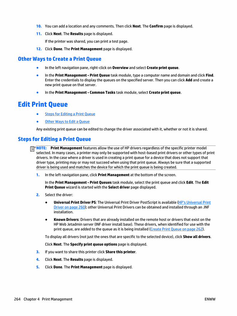
10. You can add a location and any comments. Then click Next. The Confirm page is displayed.
11. Click Next. The Results page is displayed.
If the printer was shared, you can print a test page.
12. Click Done. The Print Management page is displayed.
Other Ways to Create a Print Queue
● In the left navigation pane, right-click on Overview and select Create print queue.
● In the Print Management - Print Queue task module, type a computer name and domain and click Find.Enter the credentials to display the queues on the specified server. Then you can click Add and create anew print queue on that server.
● In the Print Management - Common Tasks task module, select Create print queue.
Edit Print Queue● Steps for Editing a Print Queue
● Other Ways to Edit a Queue
Any existing print queue can be edited to change the driver associated with it, whether or not it is shared.
Steps for Editing a Print Queue
NOTE: Print Management features allow the use of HP drivers regardless of the specific printer modelselected. In many cases, a printer may only be supported with host-based print drivers or other types of printdrivers. In the case where a driver is used in creating a print queue for a device that does not support thatdriver type, printing may or may not succeed when using that print queue. Always be sure that a supporteddriver is being used and matches the device for which the print queue is being created.
1. In the left navigation pane, click Print Management at the bottom of the screen.
In the Print Management - Print Queues task module, select the print queue and click Edit. The EditPrint Queue wizard is started with the Select driver page displayed.
2. Select the driver:
● Universal Print Driver PS: The Universal Print Driver PostScript is available (HP’s Universal PrintDriver on page 260); other Universal Print Drivers can be obtained and installed through an .INFinstallation.
● Known Drivers: Drivers that are already installed on the remote host or drivers that exist on theHP Web Jetadmin server (INF driver install base). These drivers, when identified for use with theprint queue, are added to the queue as it is being installed (Create Print Queue on page 262).
To display all drivers (not just the ones that are specific to the selected device), click Show all drivers.
Click Next. The Specify print queue options page is displayed.
3. If you want to share this printer click Share this printer.
4. Click Next. The Results page is displayed.
5. Click Done. The Print Management page is displayed.
264 Chapter 4 Print Management ENWW

Other Ways to Edit a Queue
● In the left navigation pane, right-click on Overview and select Edit print queue.
● In the Print Management - Print Queues task module, select Edit.
● In the Print Management - Print Queue task module, type a computer name and domain and click Find.Enter the credentials to display the queues on the specified server. Then you can select a queue andclick Edit.
Delete Print Queue● Steps for Deleting a Print Queue
● Other Ways to Delete a Print Queue
You can delete print queues from HP Web Jetadmin.
Steps for Deleting a Print Queue
1. In the left navigation pane, click Print Management at the bottom of the screen.
In the Print Management - Print Queues task module, click Delete. The Delete Print Queue wizard isstarted.
2. Select the print queue to delete.
3. Click Next. The Confirm page is displayed.
4. Click Next. The Results page is displayed. Click Done to display the Print Management page.
Other Ways to Delete a Print Queue
● In the left navigation pane, right-click on Overview and select Delete print queue.
● In the Print Management - Print Queues task module, select Delete.
● In the Print Management - Print Queue task module, type a computer name and domain and click Find.Enter the credentials to display the queues on the specified server. Then you can select a queue andclick Delete.
Pre-configure Driver● Steps for Pre-configuring a Driver
● Other Ways to Pre-Configure a Driver
After drivers are listed in Available Drivers, they can be pre-configured to contain settings such as duplex-onor grayscale. Many HP drivers can be pre-configured. Typically, PCL5 and PCL6 HP drivers for newerHP devices can be pre-configured in a variety of ways. Some settings can be locked.
Table 4-1 Driver Settings
Setting Lockable or Not Lockable
Duplex/Simplex Lockable
Orientation: Portrait/Landscape Not Lockable
ENWW Delete Print Queue 265
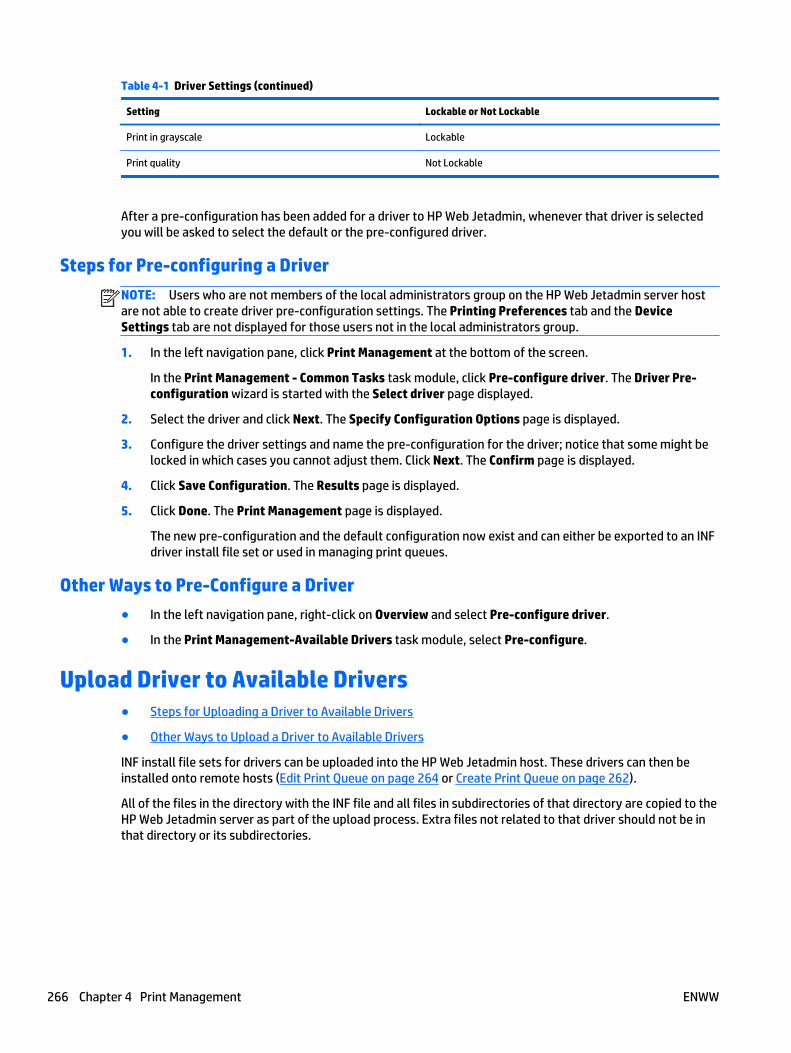
Table 4-1 Driver Settings (continued)
Setting Lockable or Not Lockable
Print in grayscale Lockable
Print quality Not Lockable
After a pre-configuration has been added for a driver to HP Web Jetadmin, whenever that driver is selectedyou will be asked to select the default or the pre-configured driver.
Steps for Pre-configuring a Driver
NOTE: Users who are not members of the local administrators group on the HP Web Jetadmin server hostare not able to create driver pre-configuration settings. The Printing Preferences tab and the DeviceSettings tab are not displayed for those users not in the local administrators group.
1. In the left navigation pane, click Print Management at the bottom of the screen.
In the Print Management - Common Tasks task module, click Pre-configure driver. The Driver Pre-configuration wizard is started with the Select driver page displayed.
2. Select the driver and click Next. The Specify Configuration Options page is displayed.
3. Configure the driver settings and name the pre-configuration for the driver; notice that some might belocked in which cases you cannot adjust them. Click Next. The Confirm page is displayed.
4. Click Save Configuration. The Results page is displayed.
5. Click Done. The Print Management page is displayed.
The new pre-configuration and the default configuration now exist and can either be exported to an INFdriver install file set or used in managing print queues.
Other Ways to Pre-Configure a Driver
● In the left navigation pane, right-click on Overview and select Pre-configure driver.
● In the Print Management-Available Drivers task module, select Pre-configure.
Upload Driver to Available Drivers● Steps for Uploading a Driver to Available Drivers
● Other Ways to Upload a Driver to Available Drivers
INF install file sets for drivers can be uploaded into the HP Web Jetadmin host. These drivers can then beinstalled onto remote hosts (Edit Print Queue on page 264 or Create Print Queue on page 262).
All of the files in the directory with the INF file and all files in subdirectories of that directory are copied to theHP Web Jetadmin server as part of the upload process. Extra files not related to that driver should not be inthat directory or its subdirectories.
266 Chapter 4 Print Management ENWW
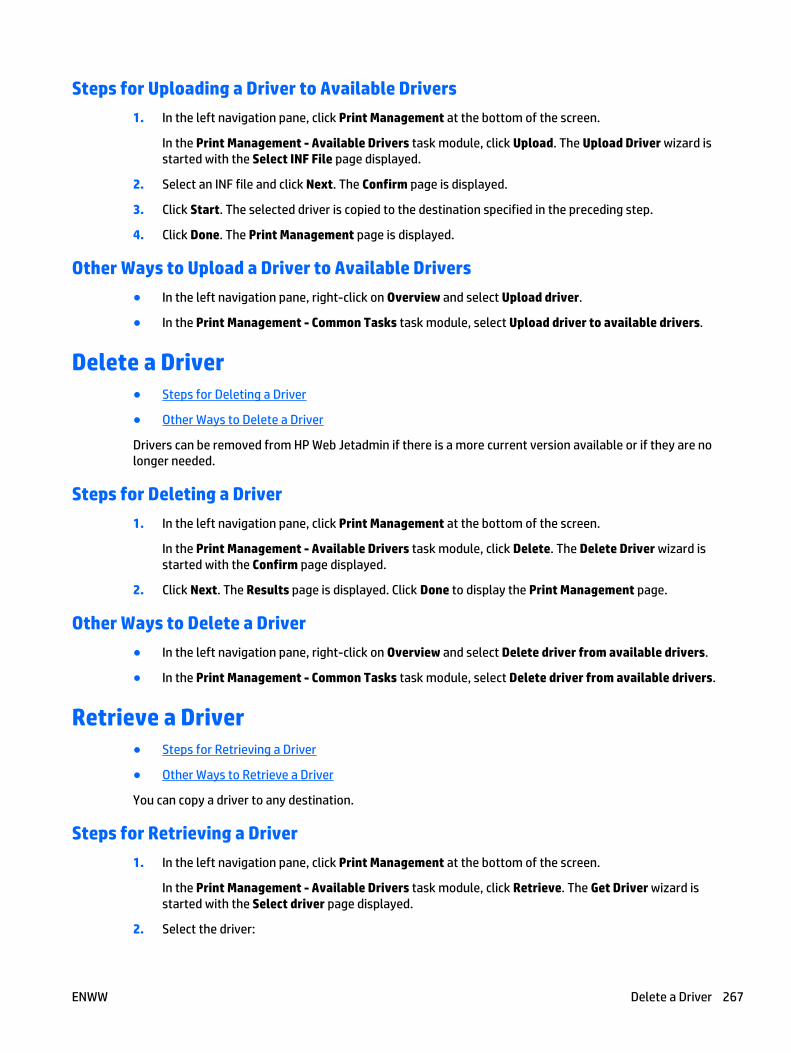
Steps for Uploading a Driver to Available Drivers
1. In the left navigation pane, click Print Management at the bottom of the screen.
In the Print Management - Available Drivers task module, click Upload. The Upload Driver wizard isstarted with the Select INF File page displayed.
2. Select an INF file and click Next. The Confirm page is displayed.
3. Click Start. The selected driver is copied to the destination specified in the preceding step.
4. Click Done. The Print Management page is displayed.
Other Ways to Upload a Driver to Available Drivers
● In the left navigation pane, right-click on Overview and select Upload driver.
● In the Print Management - Common Tasks task module, select Upload driver to available drivers.
Delete a Driver● Steps for Deleting a Driver
● Other Ways to Delete a Driver
Drivers can be removed from HP Web Jetadmin if there is a more current version available or if they are nolonger needed.
Steps for Deleting a Driver
1. In the left navigation pane, click Print Management at the bottom of the screen.
In the Print Management - Available Drivers task module, click Delete. The Delete Driver wizard isstarted with the Confirm page displayed.
2. Click Next. The Results page is displayed. Click Done to display the Print Management page.
Other Ways to Delete a Driver
● In the left navigation pane, right-click on Overview and select Delete driver from available drivers.
● In the Print Management - Common Tasks task module, select Delete driver from available drivers.
Retrieve a Driver● Steps for Retrieving a Driver
● Other Ways to Retrieve a Driver
You can copy a driver to any destination.
Steps for Retrieving a Driver
1. In the left navigation pane, click Print Management at the bottom of the screen.
In the Print Management - Available Drivers task module, click Retrieve. The Get Driver wizard isstarted with the Select driver page displayed.
2. Select the driver:
ENWW Delete a Driver 267

● Universal Print Driver PS: The Universal Print Driver PostScript is available (HP’s Universal PrintDriver on page 260); other Universal Print Drivers can be obtained and installed through an .INFinstallation.
● Known Drivers: Drivers that are already installed on the remote host or drivers that exist on theHP Web Jetadmin server (INF driver install base). These drivers, when identified for use with theprint queue, are added to the queue as it is being installed (Create Print Queue on page 262).
To display all drivers (not just the ones that are specific to the selected device), click Show all drivers.
Click Next.
3. Select the driver and the pre-configuration for the driver and click Next. The Specify destinationsettings page is displayed.
4. Select a folder for the driver and click Next. The Confirm page is displayed.
5. Click Start. The selected driver is copied to the destination specified in the preceding step.
6. Click Done. The Print Management page is displayed.
Other Ways to Retrieve a Driver
● In the left navigation pane, right-click on Overview and select Retrieve driver from available drivers.
● In the Print Management - Common Tasks task module, select Retrieve driver from available drivers.
268 Chapter 4 Print Management ENWW

5 Application Management
● All About Application Management
● Application Management Options
● Application Management Task Modules
● User Security
● HP Web Jetadmin Management
All About Application Management● Network Ports
You can use the features in the Application Management view to configure and manage devices on thenetwork. The task modules on the Overview page provide access to these features.
The following are some important things to note about HP Web Jetadmin:
● Low-privilege service account: HP Web Jetadmin runs under the Network Service account, which is alow-privilege account on the local system. Many environments require that applications such asHP Web Jetadmin do not have administrative access to the operating system.
● Database access and authentication: HP Web Jetadmin uses Windows credentials to access thedatabase instance that was created in Microsoft SQL Server Express Edition when the software wasinstalled.
● File permissions and NTFS: HP Web Jetadmin uses Windows credentials to access the databaseinstance that was created in SQL Server Express Edition when the software was installed.
Network Ports
HP Web Jetadmin opens a number of ports for various reasons. See the Installation and Setup Guide fordetailed information about Ports on page 11.
Application Management OptionsConfiguration options can be set for many functional area within the Application Management view. Formore information, see Application Management Configuration Options on page 50.
Application Management Task Modules● Application Management - Current Tasks and Common Tasks Task Module
● Application Management - Active Tasks Task Module
● Application Management - Scheduled Tasks Task Module
● Web Jetadmin - All Active Tasks Task Module
● Web Jetadmin - All Scheduled Tasks Task Module
ENWW All About Application Management 269
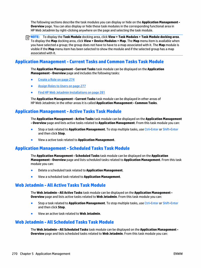
The following sections describe the task modules you can display or hide on the Application Management -Overview page. You can also display or hide these task modules in the corresponding functional area inHP Web Jetadmin by right-clicking anywhere on the page and selecting the task module.
NOTE: To display the Task Module docking area, click View > Task Modules > Task Module docking area.To display the Map docking area, click View > Device Modules > Map. The Map menu item is available whenyou have selected a group; the group does not have to have to a map associated with it. The Map module isvisible if the Map menu item has been selected to show the module and if the selected group has a mapassociated with it.
Application Management - Current Tasks and Common Tasks Task Module
The Application Management - Current Tasks task module can be displayed on the ApplicationManagement - Overview page and includes the following tasks:
● Create a Role on page 274
● Assign Roles to Users on page 277
● Find HP Web Jetadmin Installations on page 281
The Application Management - Current Tasks task module can be displayed in other areas ofHP Web Jetadmin; in the other areas it is called Application Management - Common Tasks.
Application Management - Active Tasks Task Module
The Application Management - Active Tasks task module can be displayed on the Application Management- Overview page and lists active tasks related to Application Management. From this task module you can:
● Stop a task related to Application Management. To stop multiple tasks, use Ctrl-Enter or Shift-Enterand then click Stop.
● View a active task related to Application Management.
Application Management - Scheduled Tasks Task Module
The Application Management - Scheduled Tasks task module can be displayed on the ApplicationManagement - Overview page and lists scheduled tasks related to Application Management. From this taskmodule you can:
● Delete a scheduled task related to Application Management.
● View a scheduled task related to Application Management.
Web Jetadmin - All Active Tasks Task Module
The Web Jetadmin - All Active Tasks task module can be displayed on the Application Management -Overview page and lists active tasks related to Web Jetadmin. From this task module you can:
● Stop a task related to Application Management. To stop multiple tasks, use Ctrl-Enter or Shift-Enterand then click Stop.
● View an active task related to Web Jetadmin.
Web Jetadmin - All Scheduled Tasks Task Module
The Web Jetadmin - All Scheduled Tasks task module can be displayed on the Application Management -Overview page and lists scheduled tasks related to Web Jetadmin. From this task module you can:
270 Chapter 5 Application Management ENWW
● Delete a scheduled task related to Web Jetadmin.
● Edit a scheduled task related to Web Jetadmin.
User Security● All About User Security
● User Security Task Modules
● Roles
● Users
● User Security Diagnostics
All About User Security
● Initial User Security
● The HP Web Jetadmin Administrator Role
● Alternate Log-in Method for User Security
A role is a set of permissions for HP Web Jetadmin features. HP Web Jetadmin administrators can assign localor domain users to user roles. After a user is assigned to a role, that user can access the features specified forthat role.
The following are the security features in HP Web Jetadmin:
● Advanced security technologies on the Microsoft .NET Framework platform provide authentication andencryption of client/server communications.
● Windows Active Directory integrated role-based user authentication secures the application againstunauthorized usage.
● Optional SSL (Secure Sockets Layer) communication between client browser and application serverensure data security for application file download.
● Optional Simple Network Management Protocol v3 (SNMPv3) used on devices provides authenticationand encryption.
● IPsec plug-in; using HP Web Jetadmin, you can configure an IPsec policy and then apply it to one or moreselected HP Jetdirect devices.
● Running under a low-privilege service account reducing risk of privilege escalation attacks.
● Secure online update features allow a safe easy way to get online patches updates and new features.
You can manage access to HP Web Jetadmin in User Security. You can control who has access and what theyhave access to. In User Security, you can manage:
● Role templates: Two exist to allow you to create one set of access levels and then apply that templatewhen adding users. You can create, view, edit, and delete role templates.
● Users: Allows you to assign users to a role template. You can create, view, edit, and delete users.
Initial User Security
HP Web Jetadmin is a multi-user application that can be accessed from remote client-workstations. Usersand user-permissions can be administered to control access to the application and specific features within
ENWW User Security 271
the application. An example of this would be a helpdesk scenario where many users may not require orshould not have access to features like, discovery, user permissions or, global application settings.
HP Web Jetadmin uses Windows domain identities to authenticate users and grant access to the applicationor to specified features. HP Web Jetadmin provides single-sign-on which means the user is authenticated byvirtue of being logged into their client host. They do not have to provide their credentials again when logginginto HP Web Jetadmin.
The HP Web Jetadmin Administrator Role
The HP Web Jetadmin administrator has full rights to all application settings and features. The personinstalling HP Web Jetadmin software must have local administrative privileges on the install-host andtherefore will have initial administrative access to the software. Any identity that is a member of the localadministrators group on the local host also has administrative access to the software. The identity must havelocal administrative privileges on the install-host and therefore will have initial administrative access to thesoftware.
Alternate Log-in Method for User Security
HP Web Jetadmin uses the single sign-on functionality to pass the identity of the user who is currently loggedinto Windows on the client to the server where HP Web Jetadmin is installed. HP Web Jetadmin authenticatesthis identity through the local Windows users on the server or through the Windows domain identities. Insome cases, the client and server might not reside on the same Windows security domain or on any Windowssecurity domain. If HP Web Jetadmin fails to authenticate this identity for any reason, it displays an alternatelog-in prompt. Users can then enter log-in credentials other than the credentials for the current Windowssession on the client.
The alternate log-in prompt is useful in a variety of situations, such as the following:
● An authorized HP Web Jetadmin user needs to access HP Web Jetadmin from the desktop of anunauthorized user.
● The HP Web Jetadmin server is on a security domain. The user has a log-in identity on the securitydomain that has been given access rights in HP Web Jetadmin through the Users and Roles features.However, the user's desktop is not on the security domain.
User Security Task Modules
● User Security - Current Tasks and User Security - Common Tasks Task Modules
● User Security - Roles Task Module
● User Security - Users Task Module
● User Security - Active Clients Task Module
The following sections describe the task modules you can display or hide on the User Security page in theApplication Management view. You can also display or hide these task modules in the correspondingfunctional area in HP Web Jetadmin by right-clicking anywhere on the page and selecting the task module.
NOTE: To display the Task Module docking area, click View > Task Modules > Task Module docking area.To display the Map docking area, click View > Device Modules > Map. The Map menu item is available whenyou have selected a group; the group does not have to have to a map associated with it. The Map module isvisible if the Map menu item has been selected to show the module and if the selected group has a mapassociated with it.
272 Chapter 5 Application Management ENWW

User Security - Current Tasks and User Security - Common Tasks Task Modules
The User Security - Current Tasks task module can be displayed on the User Security page and includes thefollowing tasks:
● Create a Role on page 274
● Assign Roles to Users on page 277
The User Security - Current Tasks task module can be displayed in other areas of HP Web Jetadmin; in theother areas it is called User Security - Common Tasks.
User Security - Roles Task Module
The User Security - Roles task module can be displayed on the User Security page and includes the followingtasks:
● New (Create a Role on page 274)
● Edit (Edit a Role on page 275)
● Delete (Delete a Role on page 275)
● View (Role Templates on page 276)
● Copy (Copy Template Wizard on page 85)
User Security - Users Task Module
The User Security - Users task module can be displayed on the User Security page and includes the followingtasks:
● Add (Assign Roles to Users on page 277)
● Edit (Edit Users on page 279)
● Remove (Remove Roles on page 279)
● Diagnose (User Security Diagnostics on page 280)
User Security - Active Clients Task Module
The User Security - Active Clients task module can be displayed on the User Security page.
Roles
● Restrict Roles to Device Groups
● Create a Role
● Edit a Role
● Delete a Role
● Role Templates
A role is a set of permissions for specific HP Web Jetadmin features. A permission set can apply to all of thefeatures in HP Web Jetadmin or be restricted to only the device management features for a device group. Formore information about restricting permission sets to device groups, see Restrict Roles to Device Groupson page 274.
ENWW User Security 273
After you assign a role to a user, the user can access only the HP Web Jetadmin features that are enabled forthat role. You can create multiple roles to allow different levels of access to HP Web Jetadmin features fordifferent users. You can assign multiple roles to one user.
The permission sets for roles are cumulative. If you assign one role to a user, you can grant additionalpermissions to that user by assigning another role that has a different permission set. Users never losepermissions when multiple roles are assigned to them. For example, assume that Role A enables permissionto update the device firmware and Role B disables permission to update the device firmware. If you assignRole A to a user, the user can update the device firmware. If you then assign Role B to the user, the userretains permission to update the device firmware.
You can use the Diagnostics feature to view the roles that are assigned to a user and the features that areenabled or disabled for each of those roles. For more information about the Diagnostics feature, see UserSecurity Diagnostics on page 280.
Restrict Roles to Device Groups
When you create a role, you can restrict the role to device groups and limit the permission set to specificdevice management features, such as configuring devices, running discoveries, and updating the devicefirmware. To limit the permission set to device groups from the Create Role wizard, you must select theDevice Groups option from the Restriction type list on the Specify permission settings page. Then you canenable or disable each device management feature. For instructions on creating roles, see Create a Roleon page 274.
After you create a role that is limited to the device management features, you can assign the role to a user.During the process of assigning the role to a user, you must specify the device groups to which the role isrestricted. The user can access the device management features that are enabled for the role only on thedevices that are members of the specified device groups. The user cannot access the device managementfeatures on devices that are not members of the specified device groups. For instructions on assigning roles,see Assign Roles to Users on page 277.
Create a Role
If you have permission to manage users, you can create roles by using the Create Role wizard.
To create a role, perform the following steps:
1. In the Application Management navigation pane, right-click Roles, and then select Create. The CreateRole wizard starts.
NOTE: You can assign more than one role to a user. The permission sets for roles are cumulative. Ifyou assign one role to a user, you can grant additional permissions to that user by assigning anotherrole that has a different permission set. Users never lose permissions when multiple roles are assignedto them. For example, assume that Role A enables permission to update the device firmware and Role Bdisables permission to update the device firmware. If you assign Role A to a user, the user can updatethe device firmware. If you then assign Role B to the user, the user retains permission to update thedevice firmware.
2. On the Specify permission settings page, select one of the following options from the Restriction typelist:
● None: The permission set for this role applies to all areas of HP Web Jetadmin.
● Device Groups: The permission set for this role is limited to the device management features.
NOTE: If the Device Groups option is selected, you must also specify the device groups to whichthe role is restricted when you assign the role to a user. For instructions on assigning roles, seeAssign Roles to Users on page 277.
274 Chapter 5 Application Management ENWW
3. Select the checkbox next to each permission that you want to enable for the role, and then click theNext button.
NOTE: You must enable at least one permission.
4. On the Specify role name page, enter a name for the role in the Role name box, and then click the Nextbutton.
NOTE: Each role must have a unique name.
5. On the Confirm page, verify that the information is correct, and then click the Create Role button.
6. To start the Assign User Role wizard, select the Assign to users now checkbox. For more informationabout the Assign User Role wizard, see Assign Roles to Users on page 277.
7. On the Results page, click the Done button.
Edit a Role
After a role has been created, you can edit it if necessary to change its permissions. The only role you cannotedit is the Administrator role.
NOTE: You cannot change the type of restriction for a role after the role has been created.
NOTE: If a user is logged in to HP Web Jetadmin when you change the permissions for the role to which thatuser is assigned, the changed permissions do not take effect until that user logs out and then logs back in.However, if the user continues working after you change the permissions and tries to access a feature that isno longer allowed, HP Web Jetadmin displays a message that the user no longer has permission to performthat action.
Roles can be edited by multiple clients simultaneously. The last saved user settings are the ones that will bestored for that role template.
To edit a role, perform the following steps:
1. In the Application Management navigation pane, expand the Roles option, right-click the role, and thenselect Edit. The Edit Role wizard starts.
2. To enable a permission, select the checkbox next to the permission.
-or-
To disable a permission, clear the checkbox next to the permission.
3. Click the Next button.
4. On the Specify role name page, enter a new name for the role in the Role name box, and then click theNext button.
NOTE: Each role must have a unique name.
5. On the Confirm page, verify that the information is correct, and then click the Save Role button.
6. On the Results page, click the Done button.
Delete a Role
You can delete any role in HP Web Jetadmin except for the Administrator role.
NOTE: If a user is logged in to HP Web Jetadmin when you delete the role to which that user is assigned, theclient for that user is shut down and a message displays stating that the user no longer has permission.
ENWW User Security 275
To delete a role, perform the following steps:
1. In the Application Management navigation pane, expand the Roles option, right-click the role, and thenselect Delete. The Delete Role wizard starts.
2. On the Confirm page, verify that the information is correct, and then click the Delete Role button.
3. On the Results page, click the Done button.
Role Templates
● Steps for Viewing a Role
● Copy a Role Template
Two role templates come with HP Web Jetadmin:
● Default Device Admin Role: has limited device management permissions and no applicationmanagement permissions. You can open this template, rename it, and then change permissions asnecessary.
● HP Web Jetadmin Administrator Role: a read-only role. Users assigned to this role have full rights toHP Web Jetadmin. Both users and user-groups can be added to this role. User groups that are added canbe either local or domain groups.
For information about assigning a role template or a role to users, see Assign Roles to Users on page 277.
NOTE: Even though you can create, edit, and view role templates, you cannot edit or delete theHP Web Jetadmin Administrator (Read-Only) role template.
Steps for Viewing a Role
1. In the left navigation pane, click on User Security.
In the User Security - Roles task module, select the role to change and click View. The role is displayedshowing the type of restriction and any permissions set.
2. From this page, you can:
● Edit a Role on page 275 (if it is not the Administrator role).
● Delete a Role on page 275 (if it is not the Administrator role).
● Add User (Assign Roles to Users on page 277).
● Remove User (Remove Roles on page 279).
Copy a Role Template
Role templates can be created and managed to save you time and provide consistency. Templates containconfiguration preferences (that vary by template type) and can be applied to users or user groups. For moreinformation, see Copy Template Wizard on page 85.
NOTE: Templates are also available in the Device Management view for Configuration, Alerts, Discovery,Data Collection, and Report Generation.
Users
● Managing Users within User Groups
● Assign Roles to Users
● Edit Users
276 Chapter 5 Application Management ENWW
● Remove Roles
If you have permission to manage users in HP Web Jetadmin you can add users to a role. A user can be addedto a role with all of its permissions, or that user can be added to a role with only a subset of its permissions.
Managing Users within User Groups
Either domain or local user groups can be assigned to an HP Web Jetadmin Role. Once the assignment ismade, the users contained within the user group have privileges that are defined within by the role. Here aresome examples of user groups and Role assignment.
● Example 1: a domain user group contains users who belong to the Support team. The company addsand removes users as needed when staff changes occur. The Support team’s user-group is associatedwith an HP Web Jetadmin Role named HELPDESK.
Domain User Group-Support:
AMERICAS\ralphj
EMEA\rjiminez
ASIAPACIFIC\chansen
Table 5-1 Assignments for Example 1
User Role
AMERICA\Support HELPDESK
● Example 2: a local group on the system that hosts HP Web Jetadmin includes a group named WJAUsers.This group is managed by the HP Web Jetadmin administrator who’s name is Chester. Chester keeps afew people in the group who help him administer the application. The group is associated with the built-in Role named HP Web Jetadmin Administrator (read only).
Local User Group-WJAUsers:
EMEA\Wendt
EMEA\Pacj
ASIAPACIFIC\Hae
Table 5-2 Assignments for Example 2
User Role
WJA-SYSTEM\WJAUsers HP Web Jetadmin Administrator (read only)
Assign Roles to Users
You can assign roles to users to manage the HP Web Jetadmin features that the users can access. After youassign a role to a user, the user can access only the HP Web Jetadmin features that are enabled for that role.You can create multiple roles to allow different levels of access to HP Web Jetadmin features for differentusers. You can assign multiple roles to one user.
The permission sets for roles are cumulative. If you assign one role to a user, you can grant additionalpermissions to that user by assigning another role that has a different permission set. Users never losepermissions when multiple roles are assigned to them. For example, assume that Role A enables permissionto update the device firmware and Role B disables permission to update the device firmware. If you assignRole A to a user, the user can update the device firmware. If you then assign Role B to the user, the userretains permission to update the device firmware.
ENWW User Security 277
To assign roles to users, perform the following steps:
1. In the Application Management navigation pane, right-click User Security, and then select Assign rolesto users. The Assign User Role wizard starts.
2. On the Select users or user groups page, click the Add button.
3. On the Add User page, enter the user name and domain where the user is defined.
-or-
To search for the user, perform the following steps:
a. Click the Browse button.
b. To change the location, click the Locations button. In the Locations window, select theHP Web Jetadmin or Windows domain, and then click the OK button.
c. Enter the user name. To display examples of the format for entering user names, hold the cursorover the Enter the object name to select (examples) link.
d. To validate the user name, click the Check Names button.
e. If the user name is not valid, the wizard displays an error message. Click the OK button, and thenrepeat steps c and d.
f. Click the OK button.
4. Click the Add button.
5. To add additional users, repeat steps 3 and 4.
6. Click the Close button.
7. On the Select users or user groups page, verify that the information is correct, and then click the Nextbutton.
8. To create a role from the Specify role settings page, click the New button. The Create Role wizardstarts. For instructions on using the Create Role wizard, see Create a Role on page 274.
9. Select the role from the Role list.
10. If the selected role cannot be restricted to device groups, the Add button is not available. Continue withstep 11.
-or-
If the selected role can be restricted to device groups, the Add button is available. Perform the followingsteps:
a. Click the Add button.
b. On the Select Group window, click the ... button, and then select the device group.
c. Click the OK button.
d. To add additional device groups, repeat steps a through c.
11. Click the Next button.
12. On the Confirm page, verify that the information is correct, and then click the Add button.
13. On the Results page, click the Done button.
To assign multiple roles to a user, repeat this procedure for each role that you want to assign to the user.
278 Chapter 5 Application Management ENWW
Edit Users
● Steps for Edit Users
You can change the user and role for an existing assignment.
Steps for Edit Users
1. Select Application Management from the bottom of the left navigation pane.
Expand User Security and click on Users. The User Security - Users page is displayed.
2. Select the user or group and click Edit. The Edit User Roles wizard is started with the Users pagedisplayed.
3. To change the user for the role check Change User and then type the User name and domain.
If you click Browse, the Select User page is displayed. Type the Object Type and Location and clickNext. If necessary, you can browse for locations.
4. The information will be validated. If the user is found, it will be listed in the Selected Users box at thebottom of this page. If the user is not found, verify the user name and domain and re-enter thatinformation.
5. Review the users assigned to this role shown in Selected Users.
If any should be removed, click Remove.
If the users assigned to this role template are correct, click Next. The User Security - Users page isdisplayed again.
6. Select the role from the Role drop-down box.
7. If any groups have permissions associated with them, they are listed in the Restrict Permissions byGroup box at the bottom of this page.
If any of the sets of permissions should apply to this user, click Add. This means the user will only beallowed to perform actions on the group listed.
If any of the sets of permissions listed should be removed so that the user has access to more groups,click Remove.
Click Next. The Confirm page is displayed.
8. Review the selections. If they are correct, click Next. The Results page is displayed. Click Done.
Remove Roles
● Steps for Removing Roles
Following are steps for removing roles.
Steps for Removing Roles
1. Select Application Management from the bottom of the left navigation pane.
Expand User Security and click on Users. The User Security - Users page is displayed.
2. Select the user or group and click Remove Role. The Remove User Role wizard is started with theConfirm page displayed.
3. If this is the correct user to delete, click Next. The Results page is displayed.
4. Click Done. The User Security - Users page is displayed.
ENWW User Security 279
User Security Diagnostics
● Steps for Diagnostics
User Security - Diagnostics provides analysis of permissions as they exist for an individual user or group.Any domain or local user or group can be chosen and then examined for existing permissions onHP Web Jetadmin.
Steps for Diagnostics
1. Select Application Management from the bottom of the left navigation pane.
Expand User Security and click on Diagnostics. The User Security - Diagnostics page is displayed.
2. Browse for or enter the user name and domain and then click View Roles.
3. If desired, select a restriction to filter the list displayed.
4. The role or roles and permissions for the user are displayed.
HP Web Jetadmin Management● All About HP Web Jetadmin Management
● HP Web Jetadmin Management Task Modules
● HP Web Jetadmin Installations
● Data Synchronization
All About HP Web Jetadmin Management
HP Web Jetadmin provides the ability to discover most versions of other HP Web Jetadmin installations.HP Web Jetadmin can perform a unidirectional synchronization with another HP Web Jetadmin All DevicesList (Device Lists on page 91). This makes it easy to discover devices that have already been discovered byother installations of HP Web Jetadmin. Both of these features, synchronization and application discoveryare valuable for a variety of reasons:
● An administrator detects others using HP Web Jetadmin software to attain understanding of printermanagement on the network.
● An administrator detects other HP Web Jetadmin installations as a matter of security or managementpolicy.
● An administrator is responsible for finding all devices in a distributed environment where others areresponsible for managing them in multiple areas.
HP Web Jetadmin Management Task Modules
● HP Web Jetadmin - Common Tasks Task Module
● HP Web Jetadmin - Management Task Module
● HP Web Jetadmin - Summary Task Module
The following sections describe the task modules you can display or hide on the HP Web JetadminManagement page of the Application Management view. You can also display or hide these task modules inthe corresponding functional area in HP Web Jetadmin by right-clicking anywhere on the page and selectingthe task module.
280 Chapter 5 Application Management ENWW
NOTE: To display the Task Module docking area, click View > Task Modules > Task Module docking area.To display the Map docking area, click View > Device Modules > Map. The Map menu item is available whenyou have selected a group; the group does not have to have to a map associated with it. The Map module isvisible if the Map menu item has been selected to show the module and if the selected group has a mapassociated with it.
HP Web Jetadmin - Common Tasks Task Module
The HP Web Jetadmin - Common Tasks task module includes the following tasks:
● Find HP Web Jetadmin installations (Find HP Web Jetadmin Installations on page 281).
● View HP Web Jetadmin installations (HP Web Jetadmin Installations on page 281).
HP Web Jetadmin - Management Task Module
The HP Web Jetadmin - Management task module includes the following tasks:
● Discover (Find HP Web Jetadmin Installations on page 281).
● Quick Discovery: Enter the IP address or hostname of the Web Jetadmin server and click Go.
● Launch (Launching HP Web Jetadmin on page 289).
HP Web Jetadmin - Summary Task Module
The HP Web Jetadmin - Summary task module provides summary information about how many applicationswere found and which versions were found.
HP Web Jetadmin Installations
● Find HP Web Jetadmin Installations
● Synchronizing HP Web Jetadmin Installations
● Launching HP Web Jetadmin
● Steps for Discovering Web Jetadmin on the Same Network
● Steps for Removing a Web Jetadmin Instance From the List
Sometimes it is advantageous to find other HP Web Jetadmin application installations on the network.HP Web Jetadmin provides the ability to discover most revisions of the HP Web Jetadmin software and thensynchronize with those other installations.
Using synchronization and application discovery enables you to:
● Detect others using HP Web Jetadmin software to attain understanding of printer management on thenetwork.
● Detect other HP Web Jetadmin installations as a matter of security or management policy.
● Schedule the discovery of other HP Web Jetadmin installations.
● Find all devices in a distributed environment (others might manage them in multiple areas).
Find HP Web Jetadmin Installations
● Web Service (WS) Discoveries
● IP Broadcast Discovery
● IP Range Discovery
ENWW HP Web Jetadmin Management 281
HP Web Jetadmin instances can be listed for discovery, user viewing, removing, and even launching.
HP Web Jetadmin instances can be found on both local and remote networks. The settings for IP Range and IPBroadcast are identical to HP Web Jetadmin Discovery settings. In fact, these settings are shared between thetwo features.
● HP Web Jetadmin can discover other instances of HP Web Jetadmin.
● IP Range and IP Broadcast discoveries share stored setting with other discovery features.
● HP Web Jetadmin instances can be launched directly from the discovery listing.
● The listing can be modified by performing further discoveries or by manually removing the instances.
● Address, URL, hostname, and version information are included in the listing.
Three different discovery features exist for finding HP Web Jetadmin instances:
● Web Service (WS) Discoveries on page 282
● IP Broadcast Discovery on page 282
● IP Range Discovery on page 283
You can schedule application discovery. If an application discovery is currently running and you try and startanother application discovery, you will receive a dialog asking if you want to view the current discovery orschedule a new one.
Web Service (WS) Discoveries
You can use Web Service (WS) discoveries to find other instances of HP Web Jetadmin.
NOTE: You can also use IP Broadcast and IP Range discoveries to find other instances of HP Web Jetadmin.
IP Broadcast Discovery
● IP Broadcast Discoveries for Network Devices
● IP Broadcast Discoveries for PC-Connected Devices
● Details About Running an IP Broadcast Discovery
IP Broadcast discoveries send SNMP query packets (in the form of IP broadcasts) to one or more IPnetwork(s). These are used in both PC-Connected and network device discoveries.
IP Broadcast Discoveries for Network Devices
An IP Broadcast discovery enables you to find devices or HP Web Jetadmin installations when IP broadcastaddressees are known. IP broadcast discoveries send SNMP query packets (in the form of IP broadcasts) toone or more IP network(s). One network-specific broadcast address exists for each IP subnet on an IPintranet. IP subnets are determined by the IP network number and the IP subnet mask. IP calculators,available free on the Internet, are a great way to determine IP broadcast addresses. An all 1s IP broadcast canalso be used to query the entire Intranet. Broadcasting is typically blocked by routers due to traffic spikeconcerns.
Characteristics of IP broadcast discoveries for network devices include:
● Sends SNMP queries over one or more IP broadcasts.
● Listens for replies and then qualifies network connected devices.
● Default broadcast is the Global Broadcast Address (255.255.255.255).
● Can use one or more known IP broadcast addresses with optional address descriptions.
282 Chapter 5 Application Management ENWW

● Limited checking is performed to determine if the broadcast address is valid.
● Fast and thorough, especially on a local segment.
● Most modern networks block broadcast traffic.
IP Broadcast Discoveries for PC-Connected Devices
IP broadcast discoveries for PC-Connected devices send an SNMP query to the IP broadcast address specified.An all 1s broadcast is the default. Systems with the SNMP Proxy Agent first answer with the operatingsystem. HP Web Jetadmin follows up with queries to both host and to printer specific objects. IP Broadcastdiscovery does not attempt WMI queries when no SNMP proxy agent exists.
Characteristics of IP broadcast discoveries for PC-Connected devices include:
● Settings are the same as network device.
● SNMP queries are attempted on discovered nodes.
● If no SNMP Proxy Agent response, WMI queries are performed when credentials exist in settings.
Details About Running an IP Broadcast Discovery
1. Click Edit Addresses. The Select IP broadcast addresses page is displayed.
2. You can:
● Select a broadcast address.
● Add: Add a broadcast. Type the address in Address and type a description (if desired) inDescription. Then click Add.
● Show favorites only: View only the broadcast addresses you have added by clicking Showfavorites only (at the bottom of the page).
● Remove: Remove addresses from the list by highlighting the address and clicking Delete.
● Customize: Show or hide addresses by clicking Customize. Then select an address and click AddFavorite or Remove Favorite. When done, click OK (Customizing IP Ranges for HP Web JetadminSearches on page 286).
3. Click Next.
IP Range Discovery
● Setting Realistic Ranges
● Import and Export Features of IP Range Files
● IP Range Discoveries for Network Devices
● Customizing IP Ranges for HP Web Jetadmin Searches
● IP Range Discoveries for PC-Connected Devices
● Steps for Running an IP Range Discovery
In contrast to running a broadcast discovery (where all devices or HP Web Jetadmin installations in thesubnet are queried), you can choose to discover a specified IP range or a number of IP ranges. This reducesnetwork traffic and eliminates the possibility of having unwanted devices. HP Web Jetadmin installationsshow up in the database. IP Range discovery searches for devices or HP Web Jetadmin installations within arange of IP addresses. This type of discovery is accurate and thorough but can be slow for large ranges.
ENWW HP Web Jetadmin Management 283
IP Range Discovery is effective when the administrator has knowledge of IP segments. Administrators use IPRange Discovery settings to map IP segments or groups of IP segments into HP Web Jetadmin discovery. Thismethod efficiently sweeps selected portions of the network or WAN. IP Range address pairs consist ofbeginning and ending IP addresses. IP Range discoveries first ping (send ICMP echo requests) specific IPaddresses as defined by range address pairs. If the device responds, HP Web Jetadmin follows with SNMPqueries. Multiple ranges can be specified in IP Range discoveries. HP Web Jetadmin pings in bursts of 30queries to the first set of addresses from the first range and then waits one second before sending the nextburst of 30 queries.
Setting Realistic Ranges
● Setting Ranges Based on Subnets or Contiguous Subnets
Most networks are divided up into subnets, which can be used to describe a network IP addressing schemeand are sometimes referred to as IP maps. A subnet within a large network can be described with a networknumber and a subnet mask. This is an example of one subnet with an IP range of 15.5.188.1 through15.5.191.254:
● Network number example: 15.5.188.0
● Subnet mask example: 255.255.252.0
There are 1,022 possible addresses on this subnet. It may take HP Web Jetadmin only about 10 minutes todiscover devices on this network depending on the network, the number of devices on that network, and thehost on which HP Web Jetadmin is installed.
NOTE: IP address calculators are an easy way to analyze IP networks. Many free versions of IP calculatorsexist and can be obtained on the Internet.
IP Range discovery can perform to expectations when the range data has been correctly developed. It is easyto configure ranges that are larger than needed and actually cause the discovery to take a long time andperhaps even yield little in the way of devices. For example, a class A range could easily be developed for theHP intranet but would literally take weeks to complete. On most large networks, the majority of the IPaddresses won’t answer the HP Web Jetadmin query and will cause timeouts to occur; these translate intovery long discovery times.
If you specify an IP range that is very large, your network might crash if that IP range is for a class A or class Bnetwork (when the first two octets of the IP range are not the same). HP Web Jetadmin will display a warningmessage stating that a large range might cause a large amount of network traffic; you can choose tocontinue or change the range.
You can choose to specify a large subnet range using the larger subnet address feature (Tools > Options >Shared > Discovery > Methods > IP Range > General). Large networks are considered any network biggerthan a Class B network, which has up to 65,000 nodes.
Setting Ranges Based on Subnets or Contiguous Subnets
Since large IP ranges can cause HP Web Jetadmin discovery to take long periods of time to complete, it can beuseful to use subnet ranges rather than the entire network for a discovery. These subnets, when put togetherinto one list, represent an IP map. This type of a map can be obtained from an IT or Network Infrastructureteam. It is also a good idea to work with these teams to discuss plans for implementing HP Web Jetadmindiscoveries.
NOTE: Hewlett-Packard strongly recommends that you discuss HP Web Jetadmin discoveries with yourinformation technology or network administration team.
Here is an example of IP range planning. Assume we have 20 subnets on our hypothetical network. All ofthese subnets use the same subnet mask of 255.255.255.0. Here are the network numbers that representour 20 subnets:
284 Chapter 5 Application Management ENWW

15.0.1.0, 15.0.2.0, 15.0.3.0, 15.0.4.0, 15.0.5.0, 15.0.30.0, 15.0.31.0, 15.0.32.0, 15.0.33.0, 15.0.34.0,15.0.35.0, 15.0.36.0, 15.0.37.0, 15.0.38.0, 15.0.39.0, 15.0.55.0, 15.0.64.0, 15.0.65.0, 15.0.66.0, 15.0.67.0,15.0.68.0, 15.0.69.0, 15.0.70.0, 15.0.71.0, 15.0.72.0, 15.0.73.0, 15.0.74.0
From this information, we can formulate the following IP address ranges and import them intoHP Web Jetadmin:
● 15.0.1.1-15.0.1.254
● 15.0.2.1-15.0.2.254
● 15.0.3.1-15.0.3.254
● 15.0.4.1-15.0.4.254
● 15.0.5.1-15.0.5.254
● 15.0.30.1-15.0.30.254
● 15.0.31.1-15.0.31.254
● 15.0.32.1-15.0.32.254
● 15.0.33.1-15.0.33.254
● 15.0.34.1-15.0.34.254
● 15.0.35.1-15.0.35.254
● 15.0.36.1-15.0.36.254
● 15.0.37.1-15.0.37.254
● 15.0.38.1-15.0.38.254
● 15.0.39.1-15.0.39.254
We can take the formulation one step further and simplify things. Some of the IP ranges are contiguous.These contiguously-addressed subnets are one after the other, in order, making it easy to combine them. Thefinal result would look like this:
● 15.0.1.1-15.0.5.254
● 15.0.30.1-15.0.39.254
This has reduced the number of IP ranges from 15 to 2. We can build this into a form that is easily importedinto HP Web Jetadmin and also reflects descriptions. Here is an example of data that can be imported via atext file:
● 15.0.1.1-15.0.5.254 = subnet range for western area
● 15.0.30.1-15.0.39.254 = subnet range for central area
● 15.0.55.1-15.0.55.254 = subnet range for branch office
● 15.0.64.1-15.0. 74.254 = subnet range for eastern area
Consolidating ranges makes dealing with large quantities of data simpler but may not help when descriptionsare needed for the purpose of cataloging ranges.
Import and Export Features of IP Range Files
IP range data can be developed in other tools and imported through text files. In fact, HP Web Jetadmin canexport IP range data to text files. This makes it easier to deal with large numbers of IP ranges, manipulate
ENWW HP Web Jetadmin Management 285
complex data and archive data for use in multiple instances. Tile format for IP Range import and export fileformat can be broken down as follows:
● 1 range per line
● Each IP address is separated by a hyphen character (-)
● Comment or description strings can be appended to the IP range by using an equal character (=)
Here is an example of 1 IP range with a comment: xxx.xxx.xxx.xxx-xxx.xxx.xxx.xxx=descriptive text string(where xxx represents an octet in the IP address).
There is no known limit to the number of IP ranges manageable within HP Web Jetadmin software. IP rangesare also used by other features like PC-Connected printer discovery and HP Web Jetadmin Installationsdiscovery. All IP ranges entered into HP Web Jetadmin can also be managed globally from within Tools >Options > Application Management > IP Ranges > IP Ranges.
IP Range Discoveries for Network Devices
IP Range discoveries for network devices or HP Web Jetadmin installations first send an SNMP query to alladdresses within the range. When nodes are discovered, HP Web Jetadmin performs queries to determinequalified devices. These qualified devices, when found, are added to the device lists.
Characteristics of IP range discoveries for network devices or HP Web Jetadmin installations include:
● IP ranges are simply two addresses that represent range begin and end points.
● Multiple ranges can be specified in an IP Range discovery.
● IP range data can be manually added through the user interface.
● IP ranges can be imported to HP Web Jetadmin from text files.
● Multiple IP ranges can be added and with optional, descriptive tags.
● HP Web Jetadmin sends 1 query to each address represented by the range.
● HP Web Jetadmin pings the device ranges in bursts of 30.
● HP Web Jetadmin has features to calculate IP ranges based on:
◦ Local client host
◦ WJA server host
◦ Device
● HP Web Jetadmin IP Range discoveries have proven to be effective, accurate and thorough.
● HP Web Jetadmin IP Range discoveries can be very slow if not configured properly.
● HP Web Jetadmin IP Range discoveries can draw security attention due to their scanning action.
Customizing IP Ranges for HP Web Jetadmin Searches
When you set up an IP Range discovery to search for other HP Web Jetadmin installations, you can customizethe IP ranges.
1. In the Application Management navigation pane, right-click HP Web Jetadmin Management, and thenselect Find More Applications. The HP Web Jetadmin Discovery wizard starts.
2. On the Choose discovery options page, select the IP Range option, and then click Next.
3. On the Select IP ranges page, click Customize.
286 Chapter 5 Application Management ENWW
4. To add an address to the favorites list, select the address, and then click Add Favorite.
5. To delete an address from the favorites list, select the address, and then click Remove Favorite.
6. Click OK, and then continue with the HP Web Jetadmin Discovery wizard.
IP Range Discoveries for PC-Connected Devices
IP Range discoveries for PC-Connected devices first send an SNMP query to all addresses within the range. IfSNMP communication is possible on a device, the discovery attempts to find a locally connected printer. If noSNMP communication is possible and if the user provided administrative credentials, the discovery willattempt to find a locally connected printer on the device.
Characteristics of IP range discoveries for PC-Connected devices include:
● IP Range scanning is same as network connected.
● Nodes representing hosts are detected.
● SNMP queries are attempted on discovered nodes.
● If no SNMP Proxy Agent response, WMI queries are performed when credentials exist in settings.
Steps for Running an IP Range Discovery
The Select IP Ranges page is displayed when you choose IP Range as the discovery method while:
● Creating discovery templates (Create a Discovery Template on page 154).
● Editing discovery templates (Edit a Discovery Template on page 156).
● Scheduling a discovery (Schedule a Discovery on page 151).
● Running a Web Jetadmin discovery (Find HP Web Jetadmin Installations on page 281).
On the Select IP Ranges page, you can select the IP address ranges displayed or you can edit the ranges.
1. Choose the action to take:
● Select an IP range.
● Add: Add an IP range by clicking Add. Type the range in First address and Last address; then typea description (if desired) in Description. Click Add.
To calculate a range, click Calculate range. The Calculate IP Range page is displayed:
◦ Subnet from my computer: Automatically use IP address ranges currently found on the localsubnet of your computer. You can add a description in Description if desired.
◦ Subnet from WJA server: Automatically use IP address ranges currently found on the subnetof the HP Web Jetadmin server. You can add a description in Description if desired.
◦ Subnet from network address: Type a known IP address and subnet mask. You can add adescription in Description if desired.
● Edit: Make changes to IP ranges by clicking Edit. Follow the steps in the bullet above for “Add”.
● Delete: Remove addresses from the list by highlighting the address and clicking Delete.
● Import: If desired, import a range list by clicking Import and then browse for the range list.
● Export: If desired, export a range list by clicking Export and then browse for location you want tostore the range list.
ENWW HP Web Jetadmin Management 287
● Show favorites only: View only the IP ranges you have added by clicking (at the bottom of thepage).
● Customize: Show or hide addresses by clicking Customize. Then select an address and click AddFavorite or Remove Favorite. When done, click OK.
2. Click OK.
Synchronizing HP Web Jetadmin Installations
Once discovered, other HP Web Jetadmin device details can be synchronized into the device details of theHP Web Jetadmin that performed the discovery. The devices themselves and user-selected attributes will beadded to the local All Devices list.
The control for this synchronization feature can be found in Tools > Data Synchronization. From the DataSynchronization interface you can quick-discover other HP Web Jetadmin instances, synchronize the local AllDevices list (requires credentials), schedule synchronization and manage existing synchronization schedules.
NOTE: During the synchronization process, device details from the remote HP Web Jetadmin instance areadded to the local HP Web Jetadmin database. This is not a two-way synchronization. The DataSynchronization feature on the local HP Web Jetadmin instance facilitates a one-way data transfer. For moreinformation, see Data Synchronization on page 290.
Characteristics of this data synchronization between versions of HP Web Jetadmin are:
● HP Web Jetadmin Quick Discovery can have an IP address or IP Hostname applied to it for the purposeof locating other instances of HP Web Jetadmin software.
● Once discovery has occurred, instant synchronization can be performed with HP Web Jetadmininstances.
● Synchronization requires domain user credentials that have been associated with a role on the remoteHP Web Jetadmin instance or have administrative rights on the remote system hostingHP Web Jetadmin.
● Users can select a variety of device details as part of the synchronization.
● A base set of details will always be transferred as part of the synchronization, these include:
◦ Serial number
◦ Port
◦ Model Number
◦ Last Discovered
◦ Last Communication
◦ HP Jetdirect Model
◦ IP Hostname
◦ IP Address
◦ Discovery Date/time
A local user must be in:
288 Chapter 5 Application Management ENWW
● The user group on the HP Web Jetadmin host and also be associated to a data synchronization role onthat host.
● The user group on the HP Web Jetadmin remote Smart Client.
● The admin group on the data synchronization host.
Launching HP Web Jetadmin
To launch other instances of HP Web Jetadmin, follow these steps:
1. From the left navigation pane, access Application Management.
Expand Web Jetadmin Management and click on Web Jetadmin Installations. The Web JetadminInstallations page is displayed.
2. To launch a specific instance of HP Web Jetadmin in an external browser window, highlight the instanceof HP Web Jetadmin in the Installations page and then click Launch.
If you are using HP Web Jetadmin, then the Smart Client page is displayed; you can run another instanceof the client application (Deploy the Smart Client on page 15).
Steps for Discovering Web Jetadmin on the Same Network
To discover other instances of HP Web Jetadmin running on the same network, follow these steps:
1. From the left navigation pane, access Application Management.
Expand Web Jetadmin Management and click on Web Jetadmin Installations. The Web JetadminInstallations page is displayed.
2. To discover other instances of HP Web Jetadmin, click Discover. The Web Jetadmin Discovery page isdisplayed.
3. Check one or more types of discovery to run: WS Discovery, IP Broadcast, and IP Range.
4. Click Next. The settings page is displayed for the type of discovery; if you selected more than one, thedifferent pages will be displayed in order.
5. Complete the settings page:
● Specify WS discovery settings (Web Services Discovery): Select the number of routers or hops.
● Select IP Broadcast address: Highlight the addresses.
● Select IP ranges: Select the IP ranges.
After you make your selections, click Next. A confirmation page is displayed.
6. Review your selections and click Start. A Progress page is displayed, which you can Hide. After thediscovery has been run, you can review the results and then click Done.
Steps for Removing a Web Jetadmin Instance From the List
To remove one or more instances of HP Web Jetadmin from the list of Web Jetadmin Installations, followthese steps:
1. From the left navigation pane, access Application Management, expand Web Jetadmin Managementand click on Web Jetadmin Installations. The Web Jetadmin Installations page is displayed.
2. To remove one or more instances of HP Web Jetadmin from list of Web Jetadmin Installations, clickRemove. To remove all instances of HP Web Jetadmin from the Web Jetadmin Installations list, clickRemove All. The Confirm page is displayed.
ENWW HP Web Jetadmin Management 289

3. If you need to make changes to your selections, click Back. If your selections are correct, click Next.
4. The Results page is displayed. Click Done.
Data Synchronization
You can synchronize data between HP Web Jetadmin servers on your network.
You can either enter the hostname or IP address of the HP Web Jetadmin server you want to synchronizewith, or you can discover all HP Web Jetadmin devices on your network (in Application Management underHP Web Jetadmin Management on page 280).
A local user must be in the following groups:
● The user group on the HP Web Jetadmin host and also be associated to a data synchronization role onthat host.
● The user group on the HP Web Jetadmin remote Smart Client.
● The admin group on the data synchronization host.
Data synchronization within HP Web Jetadmin software allows you to pull device details from a remoteserver and add it to your server where the feature is being invoked. All the device data from the remoteserver that is identified as part of data synchronization settings will be populated onto your server at thetime of synchronization. The sync takes place regardless of whether the devices at the remote server havealready been discovered at your server. Here is an example of data synchronization:
There are two servers: Server A with 50 devices and Server B with 100 devices. The data synchronization isinitiated from Server A. Out of the 50 devices on Server A, there are 10 that are not on Server B. Out of the100 devices on Server B, there are 75 that are not on Server A. After the synchronization occurs, Server A nowhas 125 devices (50 original ones plus 75 from Server B) and Server B still has only 100 (the 10 devices onServer A were not pushed to Server B). The data synchronization process is a “pull” process and, more thanlikely, the device numbers on the servers will not match.
To synchronize the data, perform the following steps:
1. On the top menu bar, select Tools > Data Synchronization.
2. Select the HP Web Jetadmin server you want to synchronize with.
● If you know the hostname or IP address for the HP Web Jetadmin server you want to synchronizewith, enter it in WJA Quick Discovery.
● If you do not know the hostname or IP address for the HP Web Jetadmin server you want tosynchronize with, locate and highlight the server or servers in the list.
NOTE: If the list of HP Web Jetadmin servers is empty and you do not know the IP address orhostname, go to Application Management > Web Jetadmin Management to discover otherinstances of HP Web Jetadmin.
3. Perform one or more of the following actions.
290 Chapter 5 Application Management ENWW
● Click Synchronize to synchronize the HP Web Jetadmin servers now.
● Click Schedule to set up a future time to synchronize the HP Web Jetadmin servers.
NOTE: If you schedule a task (for example, a discovery or a configuration or others) using acorresponding template, the task uses the settings defined in the template at the time the taskstarts. This makes it easy to redefine settings used in a regularly scheduled task without having todelete and create a scheduled task.
NOTE: All schedules use the date and time on the server where HP Web Jetadmin is installed. Theclient used to access HP Web Jetadmin might not be in the same time zone as the server whereHP Web Jetadmin is installed. You should be aware of the potential for time and date differenceswhen configuring schedules.
● Click Clear Schedule to clear any synchronization schedules that have been set up already.
4. The Synchronization Credentials page is displayed. Enter your password and click Verify Link to verifythe authentication. The link must be verified before you can proceed.
5. The Select device data page is displayed. Select any device data listed and then click Next
6. Click Done.
ENWW HP Web Jetadmin Management 291
6 Device Configuration Options
● Device Configuration Options for Device
● Device Configuration Options for Supplies
● Device Configuration Options for Copier
● Device Configuration Options for Network
● Device Configuration Options for Security
● Device Configuration Options for Projector
● Device Configuration Options for Wireless
● Device Configuration Options for Fax
● Device Configuration Options for Embedded Web Server
● Device Configuration Options for File System
● Device Configuration Options for Digital Sending
Following are the various configuration options for devices. Your device might or might not support all of theoptions.
Device Configuration Options for Device● Alternative Letterhead Mode
● Asset Number
● Auto Cleaning Page
● Auto Continue
● Auto Recovery
● Auto Sense Mode
● AutoSend
● AutoStore
● Browser
● Calibration Timing
● Cartridge Low Action
● Cartridge Out Action
● Clearable Warnings
● Cold Reset Media Size
● Color Supply Out
● Color/Black Mix
292 Chapter 6 Device Configuration Options ENWW

● Company Name
● Contact Person
● Control Panel Display
● Control Panel Language
● Courier Font Type
● Date and Time
● Date/Time Format
● Daylight Savings Time
● Default Input Paper Tray
● Default Media Size
● Default Media Type
● Default Print Density
● Default Printer Copies
● Delay Calibration at Wake/Power On
● Device Certificates
● Device Location
● Device Name
● Device Volumes
● Duplex Binding
● Duplex Blank Pages
● Duplex Impressions
● Economode
● Fuser Modes
● FutureSmart Level
● High Capacity Output Mode
● High Capacity Output Names
● Home Screen Applications
● Home Screen Language Selection
● I/O Timeout to End Print Jobs
● Inactivity Timeout
● Input Auto Continue
● Input Auto Continue Timeout
● Instant Lamp On
● Invalid Personality Reports
● Jam Recovery
ENWW Device Configuration Options for Device 293
● Job Hold Timeout
● Job Retention
● Job Storage Limit
● Key Press Sound
● Keyboard Layout
● Manually Feed Prompt
● Media Administration
● Optimum Speed/Cost
● Optimum Speed/Energy Usage
● Order Supplies % Level
● Original Orientation
● Outgoing Servers
● Output Auto Continue
● Override A4/Letter
● OXPd Accessory Records
● OXPd Authentication Agents
● OXPd Authorization Proxy Configuration
● OXPd Device Functions
● OXPd Enabled
● OXPd OPS Config Settings
● Paper Tray Assignments
● PCL Form Length
● PJL Configuration
● Power On Calibration
● Print PDF Errors
● Print PS Errors
● Printer Wakeup
● PS Defer Media
● Quick Sets
● Quiet Mode
● Replace Supplies
● Resolution
● Resolution Enhancement
● Restore Modes
● Rotate Offset
294 Chapter 6 Device Configuration Options ENWW

● Show Date and Time
● Show Network Address
● Size/Type Prompt
● Sleep/Wake Time
● Sleep Delay (Minutes)
● Sleep Delay Time
● Sleep Mode
● Sleep Schedule
● Sleep Timer Settings
● Stacker Staple Setting
● Stand by Fuser Mode
● Stapler Offset Mode
● Staples Out Override
● Status Page Language
● Stored Job Sort Order
● Supplies Status Messages on Control Panel
● Suppress Blank Pages
● System Setup
● System Setup Ram Disk
● Time Zone
● Time Zone/Daylight Saving
● Tray 1 Mode
● Tray Administration
● Tray Setup Media Type
● Use Another Tray
● Use Requested Tray
Configuration options for Devices define general administrative functions for the device including PowerSave, Tray Administration, and print defaults.
Alternative Letterhead Mode
When printing using duplex mode, this option defines the first side of the page as having letterhead and theother side having no letterhead.
To configure this option, select On or Off.
Asset Number
Use this option to assign an asset number to the device. The asset number can be based on any user-definedschema, such as an organization's accounting system.
ENWW Device Configuration Options for Device 295
NOTE: You can only apply this configuration option to a single device. You cannot use this configurationoption to configure multiple devices at one time or include this configuration option in a template.
Following are steps to configure this option:
1. Enter the device asset number in the box. Most devices support a maximum of 1,024 characters.
2. To apply the asset number to the device immediately, click the Apply button.
-or-
To apply the asset number to the device later, click the Schedule button. The Schedule DeviceConfiguration wizard starts. For more information about using the Schedule Device Configurationwizard, see Schedule a Device Configuration on page 166.
Auto Cleaning Page
This option enables and disables the automatic cleaning page. You can specify how often you want to printthe automatic cleaning page. If the printer is in the middle of a print job when it reaches the page count thatyou specify, the printer finishes printing that print job before it starts the cleaning process. The cleaningprocess takes approximately 2.5 minutes to complete. You can either discard or recycle the cleaning pageafter it is printed.
Following are steps to configure this option:
1. To enable Auto Cleaning Page, select Auto cleaning page enabled.
2. Select the cleaning frequency.
3. Select the page size (Letter or A4). You must use plain paper.
NOTE: To ensure that the cleaning process runs automatically and without intervention, make surethat the paper size you specify is always available in the printer.
Auto Continue
Choose to have a non-critical error message appear for ten seconds before the device resumes operation.Select Off for Auto Continue to require you to acknowledge non-critical error messages by pressingContinue on the device before the device resumes operation.
Following are steps to configure this option:
1. To enable Auto Continue, select On.
2. To disable Auto Continue, select Off. You will have to acknowledge non-critical error messages bypressing Continue on the device before the device resumes operation.
Auto Recovery
Use this option to enable or disable the Auto Recovery feature on the device. If this option is enabled and anunrecoverable error occurs in the device firmware, the device automatically turns off and turns on to recoverfrom the error.
To enable the Auto Recovery feature on the device, select the Enabled option.
To disable the Auto Recovery feature on the device, select the Disabled option.
296 Chapter 6 Device Configuration Options ENWW
Auto Sense Mode
Use this option to optimize device settings for certain media types that can be detected automatically by theprinter. Not all printers will support all of the sensing methods, or sensing from every tray. Sensing optionsmay include:
● Full Sensing: For each sheet of paper that is picked up from the tray, the product detects light paper,plain paper, heavy paper, glossy paper, tough paper, and transparencies.
● Expanded Sensing: For the first few sheets of paper that is picked up from the tray, the product detectslight paper, plain paper, heavy paper, glossy paper, tough paper, and transparencies. The productassumes the rest of the pages are of the same type.
● Transparency Only: The product distinguishes between transparencies and non-transparencies.
Following are steps to configure this option:
1. Select the setting for Tray 1 Sensing to configure how the device detects media in Tray 1.
2. Select the setting for Tray N Sensing (if available) to configure how the device detects media in trays 2through N.
AutoSend
This option enables your product to periodically send configuration and supplies usage information to arecipient list. If you have a relationship with Hewlett-Packard that provides you services such as proactivecartridge replacement, pay per page contracts, support agreements, or usage tracking, enable the Send toHP feature.
Following are steps to configure this option:
1. Check the Enable AutoSend box to enable this feature.
2. Select the frequency to send configuration and supplies information in Send every.
3. If you have a relationship with Hewlett-Packard that provides you with services such as proactivecartridge replacement, pay per page contracts, support agreements, or usage tracking, enable the Sendto HP using HTTPS feature. Information is always sent to HP securely using HTTPS POST, if possible.Otherwise, you can choose to allow this information to be sent using email if HTTPS fails or isunavailable.
4. If you want to send the same information to a custom list of web addresses or email addresses, enablethose features and enter the appropriate addresses.
AutoStore
AutoStore is an automated document and content capture solution for HP MFP devices. The AutoStoreproduct consists of a server-based application, AutoStore Server, and an installable embedded Web serverapplication, AutoStore ChaiService.
The AutoStore ChaiService contacts the AutoStore Server on a regular basis to determine whether there is anew set of AutoStore menus to download and display on the front panel of a device. To do this, it must beconfigured with the AutoStore Server information. You can also configure how frequently the AutoStoreChaiService will contact the AutoStore Server.
NOTE: To protect the AutoStore menus, use a device's authentication feature. If authentication is used,configure the AutoStore ChaiService to revoke authentication when certain events occur.
NOTE: For convenience, configure the AutoStore ChaiService to contact the AutoStore Server immediatelyfor new AutoStore menus, especially when the administrator is testing a newly designed set of AutoStoremenus.
ENWW Device Configuration Options for Device 297

After AutoStore is installed and configured, the front panel on a device or group of devices displays theAutoStore menus. These menus allow users to easily scan, process, and route documents to pre-programmed destinations. For example, an MFP device scans the documents, and then the AutoStore Serverprocesses and then routes the documents to a destination.
NOTE: If the AutoStore ChaiService is installed on a device(s), you must configure the AutoStoreChaiService to use the service.
NOTE: HP Web Jetadmin does not display the current configuration settings in this section. You can useHP Web Jetadmin to change the configuration settings. To view the configuration settings, you must useHP Web Jetadmin to browse to the device embedded Web server.
Following are steps to configure this option:
1. Select either IP Address or Hostname and then type the IP address or hostname in the correspondingtext box.
2. Type the network port value in Port (1 to 9999).
3. To specify how often to poll the AutoStore Server, type the interval (in minutes) in Interval.
4. If displayed, set the Authentication timeout.
5. If displayed and if desired, select Revoke authentication on reentry.
6. Click Apply.
Browser
Use this option to configure specific settings for the web browser on the device (for example, enabling OXPd1.6 support). The web browser settings that can be configured include connection timeout, response timeout,and a list of trusted sites.
Following are steps to configure this option:
1. To set the connection timeout, select an option from the drop-down list.
2. To set the response time, select an option from the drop-down list.
3. Enter trusted sites in the Trusted sites text box. For multiple sites, use a semicolon to separate eachentry.
Calibration Timing
Use this option to control when calibrations are performed. You can set the timer (in hours) to turn on or offcalibration. If a time is set, the calibration takes place after the timer expires and the next job is finishedprinting.
To set this option, select a time from the dropdown box and click Apply.
Cartridge Low Action
This option lets you specify how the printer responds when a toner-low condition exists. Set the printer tocontinue normal operations or set it to stop printing. In either case, HP Web Jetadmin displays a Toner Lowmessage on the Device Status page. Allowing the printer to continue printing when the toner is low lets thecurrent print job finish printing and gives the user who is responsible for the printer time to change the tonercartridge. However, this might result in poor print quality.
Following are steps to configure this option:
298 Chapter 6 Device Configuration Options ENWW
1. To let the printer continue printing when the toner is low, select Continue.
2. To stop the printer from printing until the toner is replaced, select Stop.
Cartridge Out Action
This option lets you specify how the printer responds when a toner-out condition exists. Set the printer tocontinue normal operations or set it to stop printing. In either case, HP Web Jetadmin displays a Toner Outmessage on the Device Status page. Allowing the printer to continue printing when the toner is out lets thecurrent print job finish printing and gives the user who is responsible for the printer time to change the tonercartridge. However, this might result in poor print quality.
Following are steps to configure this option:
1. To let the printer continue printing when the toner is out, select Continue.
2. To stop the printer from printing until the toner is replaced, select Stop.
Clearable Warnings
This option lets you determine whether a warning is cleared on the control panel or when another job is sent.
Following are steps to configure this option:
1. Select On to display a warning until GO is pressed.
2. Select Job to display a warning until the end of the job in which it was generated.
If On is selected, a warning is displayed until GO is pressed. If Job is selected, a warning is displayed until theend of the job in which it was generated.
Cold Reset Media Size
This option returns or sets the media size that is used as the Default Media Size when a cold reset occurs.Different countries/regions require different default media sizes. The factory uses this option to select thedefault media size.
Following are steps to configure this option:
1. To set the Cold Reset Media Size option, select the option for the media size.
2. Click Apply.
Color Supply Out
This option lets you specify how the printer responds when one of the color toners is empty. You can chooseto set the printer to continue printing with black toner (for a certain number of pages) or set it to stopprinting altogether. In both cases, HP Web Jetadmin displays a Toner Out message on the device lists.
Following are steps to configure this option:
1. To stop the printer from printing until the toner is replaced, select Stop.
2. To let the printer continue printing with black toner, when one or more of the color toners is out, selectAuto Continue Black.
Color/Black Mix
This option optimizes the performance or cost per page depending on the expected color content of typicalprint jobs. This feature allows you to set printer behavior for printing mostly color or mostly black(monochrome) print jobs.
ENWW Device Configuration Options for Device 299
NOTE: Selecting the Print In Grayscale feature from the printer driver overrides these settings for aspecific print job.
Following are steps to configure this option:
1. Auto: (Default) best choice for most conditions; it behaves the same as Mostly Color Pages.
2. Mostly Color Pages: Provides the best performance for most conditions, especially when mostly colorpages are printed. Under normal usage, there is minimal or no cost per page impact from this selection.
3. Mostly Black Pages: Provides the best cost per page for users printing mostly monochrome pages oncolor printers.
Company Name
The company contact is the name of the organization that owns or is responsible for the device.HP Web Jetadmin displays the company contact on the Status page for the device and on several of thedevice lists. You can also search for and display a list of all of the devices for which a specific organization isresponsible.
Contact Person
Use this option to specify the name of the person who should be contacted if there are any problems with thedevice or if you need support.
To set this option, type the name of the contact person.
Control Panel Display
This option lets you make specific items appear on the Control Panel Display on the device. The items includeIP Address, Hostname, Serial Number, Asset Number, Device Name, System Location, System Contact, DeviceLocation and a short text string that you can define.
One option can be selected.
Select the desired option. If you select Other, enter the message to display on the control panel.
Control Panel Language
This option lets you specify the language that is displayed on the printer control panel. The drop-down listcontains all of the languages that the printer supports. If you have a multilingual workforce, set the controlpanel language to the one language that your employees prefer.
Choose the desired language from the drop-down list.
Courier Font Type
This option allows you to choose whether the regular courier font or a dark font is used. This setting does notaffect fax or copy jobs, but does apply to the internal reports which contain a Courier font. The regularTrueType Courier font prints somewhat lighter than the bitmap fonts for the same.
To specify the courier font type, select Regular or Dark.
Date and Time
This option allows you to remotely specify the time and date for a device or group of devices. When thecorrect time and date is set on a device, the device can complete time or date dependant operations and addtime and date stamps on documents, such as a diagnostic report.
300 Chapter 6 Device Configuration Options ENWW

To specify the time and date on a device, type the current year, month, and day in the corresponding fields.Use the 12-hour system. For example, 1 PM is 1 PM.
Date/Time Format
Use this option to specify the format for dates and times as displayed on the device. Specifying the formatallows you to comply with the formats used by your organization.
To specify the date format, select a format from Date format. To specify the time format, select a timeformat from Time format.
Daylight Savings Time
Use this option to specify the date range for daylight saving time (summer time), which should match thedaylight saving time schedule for the location of the device.
Following are steps to configure this option:
1. To specify the start date and end date for daylight saving time, perform the following steps:
a. In the Start Date and End Date columns, select the appropriate values from the Occurrence, WeekDay, Month, and Hour drop-down lists.
b. Type the number of minutes for the daylight saving time offset in the DST Offset text box.
2. To use the default start date and end date for daylight saving time, select the Use Defaults option.
Default Input Paper Tray
This option lets you specify which tray the device should first get paper from as a default (upper paper tray orlower paper tray).
Select the paper tray you want to use for a default.
Default Media Size
This option lets you specify the default media size. The drop-down list contains all of the media sizes that theprinter supports. This option is useful if the people who use the printer typically print on a specific size ofmedia. For example, if the printer is dedicated to the legal department and those users typically print onLegal paper, set the default media size to Legal.
The media size setting that you might select when printing a job overrides the setting specified here.
To specify the default media size, select the media size from the drop-down list labeled Default Media Size.
Default Media Type
This option specifies the default media type. The drop-down list contains all of the media types that theprinter supports. This option is useful if the people who use the printer typically print on specific media. Forexample, if the printer is dedicated to the human resources department and they typically print on three-holepunched paper, set the default media type to Prepunched.
NOTE: For this option to work, you must specify the media type for each tray under the TrayAdministration category on the Device Configuration page.
The media type setting that a user selects when printing a job overrides the setting specified here.
To specify the default media type, select the media type from the drop-down list.
ENWW Device Configuration Options for Device 301
Default Print Density
This option lets you select the default density for print jobs, which affects all pages printed on the device(host print jobs, received faxes, copies, and internal reports).
To select this option, select a density from the drop-down box (5 is the darkest, or highest density). For color,select the desired print density for each color. If applicable, you can also select the print density forhighlights, midtones, and shadows.
Default Printer Copies
This option lets you specify the default number of copies that are printed for each print job. This option isuseful if the people who use the printer typically print a specific number of copies. For example, if the printeris dedicated to the legal department and those users always print three copies of their documents, set thedefault number of copies to three.
NOTE: The copies setting that you select when printing a job overrides the setting specified here.
To specify the default number of printer copies, type the number of copies into Default Printer Copies.
Delay Calibration at Wake/Power On
Use this option to control the timing of the calibration when the printer wakes up or is turned on.
Following are steps to configure this option:
1. To set the printer to calibrate immediately when it wakes up or is turned on, select Off. The device willnot print any jobs until it finishes calibrating.
2. To enable a device that is asleep to accept print jobs before it calibrates, select On. The device onlyaccepts new jobs for a short time. It may start calibrating before it has printed all the jobs it hasreceived.
NOTE: For best results, allow the device to calibrate before printing. Print jobs performed before calibrationmight not be of the highest quality.
Device Certificates
Use this option to configure the SSL trusted CA certificates (public keys) used for web browsing from thedevice to external web sites (for example, enabling OXPd 1.6 support). You can add, delete, and view devicecertificates. If there are no device certificates in the device's certificate store, the device uses the HP JetdirectCA certificate, if any.
Following are steps to configure this option:
1. If you are configuring this option for multiple devices at the same time, select one of the followingoverwrite options:
302 Chapter 6 Device Configuration Options ENWW
● Replace/overwrite existing Certificates
● Append to existing Certificates
● Remove Certificates
2. To add device certificates to the device, click Add. The Add Device Certificate dialog is displayed listingall of the device certificates in the Certificate Repository. Highlight the device certificates you want toadd, and then click OK.
To manage the list of device certificates, click Edit. The Certificate Repository dialog is displayed. Youcan import, delete, and view the device certificates in the repository.
3. To delete device certificates from the device, highlight the device certificates, and then click Remove.The device certificates are removed from the list of certificates on the device.
NOTE: When you delete device certificates from the device, the device certificates remain in theHP Web Jetadmin Certificate Repository. To import, delete, and view device certificates, go to Tools >Options > Device Management > Configuration > Certificate Repository.
Device Location
This option identifies the device based on its location. You can use the Device Location to search for anddisplay a list of all of the devices that have specific text in their device locations (for example, North Bldg, 3rdFloor).
HP Web Jetadmin displays the Device Location on the device lists if you configured this option to be listed(Device Identification on page 26 and Columns for Device Lists on page 93). You can also choose to have thiscolumn display in any custom view (Customizing Layouts for Device Lists on page 96).
To configure this option, enter a description of the location in the text box. The maximum number ofcharacters is 1,024.
NOTE: Some devices do not support a maximum of 1,024 characters.
Device Name
This option identifies the device based on its name. You can use the Device Name to search for and display alist of all of the devices that have specific text in their device names (for example, Color LaserJet Marketing).
HP Web Jetadmin displays the Device Name on the device lists if you configured this option to be listed(Device Identification on page 26 and Columns for Device Lists on page 93). You can also choose to have thiscolumn display in any custom view (Customizing Layouts for Device Lists on page 96).
To set the device name, type or change the device name in Device Name.
Device Volumes
This group of options selects the volumes of certain sounds emitted by the device:
NOTE: Some of the volume options may not be displayed depending on available features of the devicebeing configured.
● Line monitor: Allows you to set the volume level used during the fax machine to fax machinenegotiation for each sent and received fax.
● Alarm: Allows you to set the volume level used by the device for the beep to indicate an error condition.
● Ring: Allows you to set the volume level used to indicate an incoming call on the connected phone line.
● Key press: Allows you to set the volume level used when control panel keys are pressed.
ENWW Device Configuration Options for Device 303
To select the volume options, select Off, Soft, Medium, or Loud.
Duplex Binding
This option allows you to specify default action about whether to print on both sides of paper when the printjob does not specify a preference. Ability to specify the default duplex behavior of the printer can be usefulfor implementing policy by system administrators where the print job is not particular about this aspect ofthe job.
To select the default duplex action of the printer, select one of the options from the drop-down box: None,Long Edge (recommended for portrait print jobs), or Short Edge (recommended for landscape print jobs).
Duplex Blank Pages
This option lets you optimize the duplex printing performance.
Select Auto to enable enhanced print speed in some circumstances by often not taking the time to print blanksides. For paper types that need to print the blank side (like letterhead), Auto is smart enough to do so.
Select Yes to always print blank sides in duplex jobs. The image will always be on the correct side.
Duplex Impressions
This option lets you define how a device counts pages. This option also includes an Opt in agreement to makethe user aware that once enabled, this setting cannot be disabled. Each user is required to opt-in before theywill be able to set this configuration.
Following are steps to configure this option:
1. Click "Opt In" to enable.
2. The HP Print Tracker Usage Change agreement is displayed. Carefully review the document. If youaccept the terms, select I accept. If you do not accept the terms, this option cannot be enabled.
3. To enable this option, check the box Enable duplex impression counting.
Economode
This option allows you to select the Economode (toner saving) default for jobs that do not specify anEconomode value. This allows the printer to behave in a consistent manner for print jobs which do not specifythe Economode setting.
To specify the default Economode value, select the radio button for the desired Economode (On or Off).
Fuser Modes
Use this option to specify the fuser temperature mode for all the media types that the device supports. Youcan associate a different fuser temperature mode with each media type. If your environment experiencesvariable humidity conditions, changing the fuser temperature mode can maximize the print quality.
To configure the fuser mode for a media type, select the fuser mode from the drop-down list. For moreinformation about the appropriate fuser modes for a specific device, see the device documentation.
NOTE: When configuring this option in batch mode, a list of all the media types and fuser modes that areavailable on all the supported devices displays. If you specify a media type or fuser mode that a selecteddevice does not support, the setting is ignored for that device.
304 Chapter 6 Device Configuration Options ENWW
FutureSmart Level
Each version of the HP FutureSmart firmware can include multiple levels of functionality. HP Web Jetadmindisplays the range of firmware levels that are available in the HP FutureSmart firmware that is installed onthe device. Use this option to specify the level of the HP FutureSmart firmware version that the device uses.
NOTE: This configuration option is available for HP FutureSmart 3 or later.
NOTE: For more information about HP FutureSmart, see the HP FutureSmart Solution Web site.
To configure this option, enter the firmware level in the box. If the firmware level is outside of the range oflevels that are available on the device, HP Web Jetadmin automatically changes the firmware level to thenearest minimum or maximum level that the device supports.
After HP Web Jetadmin applies the firmware level to the device, the device automatically restarts.
High Capacity Output Mode
This option lets you specify which high-capacity output accessory the printer directs output to. Directingoutput to various high-capacity output accessories can help reduce how much time you spend going to theprinter and removing output from full bins. This is particularly useful for very large print jobs or busyprinters.
To set the high-capacity output mode, select one of the output accessory options.
High Capacity Output Names
Use this option to assign unique names to the printer multibin mailboxes. After you assign a name to amailbox, users can direct their output to a specific mailbox. For example, you might want to name mailboxesafter departments or individuals within a department.
NOTE: You can only apply this configuration option to a single device. You cannot use this configurationoption to configure multiple devices at one time or include this configuration option in a template.
To configure this option, type the name in the text box next to the mailbox.
Home Screen Applications
Use this option to specify which applications are displayed on the device control panel, specify the order inwhich the applications are displayed, and move applications into and out of the Quick Sets folder.
Third-party applications might be included in the list of applications. However, other tools might controlwhether these applications are displayed or hidden on the device control panel.
The Quick Sets folder appears in the main list of applications. Only one Quick Sets folder is allowed. QuickSets applications can reside in the main list of applications or in the Quick Sets folder. Applications in theQuick Sets folder are displayed immediately after the folder, and the application names are indented. You canmove applications in the Quick Sets folder up or down in the list or move them out of the folder into the mainapplication list. However, you can only move Quick Sets applications from the main application list into theQuick Sets folder.
Each application has a corresponding checkbox that specifies if the application is displayed or hidden on thedevice control panel. The first row of the table contains a master checkbox that controls the checkboxes forall the applications. If you select the master checkbox, the checkboxes for all the applications are selected. Ifyou clear the master checkbox, the checkboxes for all the applications are cleared. Selecting or clearing thecheckbox for an application does not affect the status of the master checkbox. The following describes howthe checkboxes for the Quick Sets folder and the applications in the folder behave:
ENWW Device Configuration Options for Device 305
● If you select the checkbox for the Quick Sets folder, the status of the checkboxes for all the applicationsin the folder remains unchanged.
● If you clear the checkbox for the Quick Sets folder, the checkboxes for all the applications in the folderare also cleared.
● If you select the checkbox for an application in the Quick Sets folder, the checkbox for the Quick Setsfolder is also selected. The Quick Sets folder must be displayed on the device control panel if any of theapplications in the folder are to be displayed.
● If you clear the checkbox for an application in the Quick Sets folder, the status of the checkbox for theQuick Sets folder remains unchanged.
For batch configurations and templates, the checkboxes initially contain a blue square. When you select acheckbox with a blue square, the checkbox is cleared. In a batch configuration or template, the Home ScreenApplications configuration option is not valid if all the checkboxes contain a blue square. At least onecheckbox must be cleared or selected.
The applications are displayed on the device control panel in the order in which they appear in the table. Youcan move applications up or down relative to one another. You can also move Quick Sets applications intoand out of the Quick Sets folder. The buttons to the right of the table are enabled or disabled depending onwhich application you select.
Following are steps to configure this option:
1. To display all the applications on the device control panel, select the master checkbox in the Show/Hidecolumn.
-or-
To hide all the applications on the device control panel, clear the master checkbox in the Show/Hidecolumn.
2. To display an application on the device control panel, select the corresponding checkbox in the Show/Hide column.
3. To hide an application on the device control panel, clear the corresponding checkbox in the Show/Hidecolumn.
4. To change the order in which the applications are displayed on the device control panel, select anapplication in the main application list or in the list of applications in the Quick Sets folder, and thenclick one of the following buttons:
● Move to top: Moves the selected application to the first row in the appropriate list.
● Move up: Moves the selected application up one position in the appropriate list.
● Move down: Moves the selected application down one position in the appropriate list.
● Move to bottom: Moves the selected application to the last row in the appropriate list.
5. To move a Quick Sets application from the main application list into the Quick Sets folder, use the Moveup and Move down buttons to position the application immediately after the Quick Sets folder. Selectthe application, and then click the Move in button. The selected application is positioned at the end ofthe list of applications in the folder.
6. To move a Quick Sets application from the Quick Sets folder into the main application list, select theapplication, and then click the Move out button. The selected application is positioned in the mainapplication list immediately after the Quick Sets folder.
7. To restore the order of all the applications to the order that they were in when you accessed thisconfiguration option, click the Reset button.
306 Chapter 6 Device Configuration Options ENWW
Home Screen Language Selection
Use this option to enable or disable the Language Selection button on the device control panel. If you enablethe Language Selection button, users can select a different language for the control-panel display duringtheir session.
For some devices, if you enable the Language Selection button, you can specify up to four alternatelanguages for the control-panel display and the default keyboard layout for each alternate language.
For some devices, you can specify the default keyboard layout for all the available languages. You can alsoenable or disable the alternate keyboard layout button on the keyboard screens. If you enable the alternatekeyboard layout button, you can specify which keyboard layouts are available.
Following are steps to configure this option:
1. To enable the Language Selection button on the control panel, select the Show the language Selectionbutton checkbox.
NOTE: Depending on the device you are configuring, perform step 2 or step 3. To display a list ofdevices that support the settings, hold the cursor over the Home Screen Language Selection title barabove the settings.
2. To specify the alternate languages and keyboard layouts, perform the following steps:
a. Select the alternate language from the list.
b. Select the default keyboard layout for the language from the corresponding list.
3. To specify the keyboard layouts for all the available languages and any alternate keyboard layouts,perform the following steps:
a. Select the keyboard layout for each language from the corresponding list.
b. To enable the alternate keyboard layouts, select the Display the alternate keyboard buttoncheckbox.
NOTE: If you select the Display the alternate keyboard button checkbox, you must also selectat least one of the available keyboard layouts.
c. To enable all the available keyboard layouts, select the All Keyboard Layouts checkbox.
-or-
To enable specific keyboard layouts, clear the All Keyboard Layouts checkbox, and then select thecheckbox next to each keyboard layout you want to enable.
I/O Timeout to End Print Jobs
This option lets you select the amount of time the device should wait between packets of data on a print jobbefore canceling that job.
To configure this option, select how long the printer waits from the drop-down list.
Inactivity Timeout
Use this option to specify the number of seconds that the device can remain inactive before automaticallyreverting to the Home screen. This timeout setting applies only when a user accesses a screen other than theHome screen, and then no further action occurs on that screen for the specified number of seconds.
To configure this option, enter the number of seconds in the box. Valid values are from 10 to 300.
ENWW Device Configuration Options for Device 307
Input Auto Continue
This option lets you specify the default action that the printer takes when the specified media size or type isnot available. It also lets you specify how long the printer waits before performing the default action.Specifying a default action for the printer to take when the specified media size or type is not available allowsthe printer to finish printing the current job without user intervention.
To specify the action for the printer if the specified media size or type is not available, select the desiredaction from the Input Auto Continue drop-down list.
Input Auto Continue Timeout
This option lets you specify how long the printer waits before performing the default action when thespecified media size or type is not available. Specifying how long the printer should wait before taking thedefault action when the specified media size or type is not available allows you time to manually correct theissue.
To specify the action for the printer if the specified media size or type is not available, select how long theprinter waits from the drop-down box.
Instant Lamp On
Enable this option to keep the scanner lamp warm when the scanner is turned on. Disabling this option savesenergy when the scanner is not in use but the scanner lamp turns off after a period of inactivity and will needto warm up before scanning again.
To configure this option, select:
● Enabled: the scanner lamp remains warm and ready to scan when not in use, but uses more energy.
● Disabled: the scanner lamp saves energy when not in use, and will need to warm up before scanningagain.
Invalid Personality Reports
Use this option to determine whether invalid personality reports are enabled or disabled for a product.
To configure this setting, select Enabled or Disabled.
Jam Recovery
This option allows you to select the default device reprint behavior after a paper jam is cleared on a faxreceive, copy, or print job. The settings include:
● Disabled: The device will never reprint a page after clearing a paper jam.
● Enabled: The device will always reprint a page after clearing a paper jam.
● Auto: The device will reprint a page after clearing a paper jam, if the installed memory is greater than7 MB.
To select the jam recovery behavior, select the desired setting (Disabled, Enabled, or Auto).
Job Hold Timeout
This option lets you specify how long the printer holds a print job that has not printed before automaticallydeleting the print job.
CAUTION: Selecting Never Delete could cause the printer’s hard disk to fill up with print jobs that were heldbut never released for printing.
308 Chapter 6 Device Configuration Options ENWW
Select the timeout value from the Job Hold Timeout drop-down list.
Job Retention
This option lets you enable and disable the job retention feature. The job retention feature is available onsome printers that have mass storage capability. This allows you to store print jobs in the flash memory on aprinter. The job retention feature allows you to complete the following tasks:
● Store a print job on the printer. You can then call the print job from the printer control panel as needed.This feature is useful for storing forms and other commonly shared documents.
● Store secure private copies to hold a print job until a user releases it by entering a personalidentification number. Print one copy of a multiple-copy print job for proofing. The user can thenrelease the remaining copies for printing or cancel them.
CAUTION: If the job retention feature is disabled, the option appears on the printer driver user interface butdoes not store the print job on the printer.
Following are steps to configure this option:
1. To enable the job retention feature, click Enable.
2. To disable the job retention feature, click Disable. If the job retention feature is disabled, the optionappears on the printer driver user interface but does not store the print job on the printer.
Job Storage Limit
This option lets you specify how many jobs can be stored on the printer hard disk at the same time.
Key Press Sound
Use this option to specify whether or not the printer emits a sound when a key is pressed in its control panel.
To configure this option, select On or Off.
Keyboard Layout
Use this feature to set the keyboard layout on your device's control panel to your language.
To use this option, select your language.
Manually Feed Prompt
Use this feature to specify whether Manual Feed Prompt will be displayed always, or only if the tray is notloaded.
If you select Always (default), the system always generates a prompt before pulling from the multipurposetray.
If you select Unless loaded, the system generates the prompt only if the multipurpose tray is empty or if it isconfigured for a different type or size.
Media Administration
This option allows you to enable or disable the media types that the printer uses. You can also define yourown media types.
Following are steps to configure this option:
ENWW Device Configuration Options for Device 309
1. To enable a media type, select the check box next to the media type.
2. To disable a media type, clear the check box next to the media type.
3. To define a new media type, type the media name in Media Types. Select the check box next to themedia type to activate it.
Optimum Speed/Cost
This option optimizes the performance or cost per page depending on the expected color content of typicalprint jobs. You can choose whether print quality is more important or whether speed of the print job is moreimportant.
To specify the optimum speed or cost per page, select one of the options (Auto, Speed, or Cost Per Page).
Optimum Speed/Energy Usage
Use this option to configure the optimum speed and energy usage for the device. This setting controls thefuser cooling behavior on the device.
To configure this option, select one of the following options from the list:
● Faster First Page: Power to the fuser is not turned off between jobs. This option has no impact on thefirst page out time.
● Save Energy: Power to the fuser is turned off after the device has been idle for 55 minutes. This optionhas a minimal impact on the first page out time because it affects only the first print job the devicesends after it has been idle for 55 minutes or longer.
● Save Most Energy: Power to the fuser is turned off after each job. This option has the most impact onthe first page out time because it affects every print job the device sends, regardless of how long thedevice has been idle.
Order Supplies % Level
Use this option to configure the low threshold for supplies.
To set this option, type the desired value in the text box (0-100).
Original Orientation
This option lets you specify the default orientation of the information on the printed page. This is useful if thepeople who use the printer typically print with a specific orientation. For example, if the printer is dedicatedto the accounting department and those users typically print spreadsheets with many columns, set thedefault orientation to Landscape to show as many columns as possible on one page.
NOTE: The orientation setting that you select when printing a job overrides the setting specified here.
Following are steps to configure this option:
1. To print across the narrow side of the media, select Portrait.
2. To print across the wide side of the media, select Landscape.
Outgoing Servers
Use this option to configure the SMTP servers that the device uses to send outgoing emails for the followingfunctions:
310 Chapter 6 Device Configuration Options ENWW
NOTE: The functions that are available vary depending on the device.
● Internet Fax
● Alerts
● AutoSend
Following are steps to configure this option:
NOTE: The following configuration options are not available for some devices.
1. If you are configuring multiple devices, select one of the following options in the Overwrite optionssection:
● Replace/overwrite existing lists: Any existing SMTP servers on the device are replaced with thelists shown here. Any existing servers that are not defined here are deleted.
● Append to existing lists:
If Overwrite any existing items with the same name is not selected, existing servers on thedevice are not changed. Any servers defined here are added to the device, unless a server alreadyexists with the same name for the same function.
If Overwrite any existing items with the same name is selected, existing servers on the deviceare not changed, unless a server is defined here with the same name. Any servers defined here areadded to the device, and if the name matches an existing server for a particular function, its valuesis changed to those defined here.
2. To add an SMTP server, perform the following steps:
a. Click the Add button.
b. On the Add Server window, enter the hostname or IP address of the SMTP server in the Servername or address box. The SMTP server name must be unique.
-or-
To search for the available SMTP servers, click the Find Servers button. On the Find Serverswindow, select the SMTP server from the list, and then click the OK button.
NOTE: The Find Servers button is available only if you are configuring a single device.
c. In the Port number box, enter the port number. The default is port 25.
d. From the Split emails if larger than list, select the maximum size for emails. The device splitsmultiple-page scanned documents that are larger than this value into multiple emails based onthe page boundaries.
e. To enable SMTP server authentication, select the Server requires authentication checkbox, andthen select one of the following options:
● Use credentials of user after sign in at control panel: The device uses the credentials of theuser who is signed in on the device to access the SMTP server.
● Use credentials defined below: The device uses the specified credentials to access the SMTPserver. Enter the credentials in the User name (maximum of 128 characters) and Password(maximum of 128 characters) boxes.
ENWW Device Configuration Options for Device 311

To test the SMTP server and credentials, enter an email address in the Send test email tobox, and then click the Test Server button.
NOTE: The Test Server button is available only if you are configuring a single device.
f. In the Server usage section, select the checkboxes for the functions that use this SMTP server.
3. To edit an SMTP server, select the SMTP server from the list, and then click the Edit button. On the EditServer window, edit the settings, and then click the OK button.
4. To delete an SMTP server from all of the functions, select the SMTP server from the list, and then clickthe Remove button. On the Confirm Remove window, click the OK button.
5. To delete all of the SMTP servers from all of the functions, click the Remove All button. On the ConfirmRemove window, click the OK button.
6. To change the order of the SMTP servers for a function, select the SMTP server from the list, and thenclick the up and down arrows to the right of the function. The device contacts the SMTP servers in theorder in which they are listed.
Output Auto Continue
This option allows you to control the behavior of the device if a print job is submitted which lets you specify apaper tray and/or paper size which does not match the current device configuration. This allows the printerto behave in a consistent manner in case of a conflict between the print job specification and the printerconfiguration.
Following are steps to configure this option:
NOTE: The options available are dependent upon the device.
1. Output overflow command: Specifies the default action to take when the output bin is full or when thestapler is empty.
2. Output auto continue timeout: Specifies how long before the device should wait before taking theaction specified in the output overflow command.
3. Output overflow bin: Specifies what bin should be used if the primary bin is full.
Override A4/Letter
Use this option to print on letter-size paper when an A4 job is sent but no A4-size paper is loaded in thedevice, or to print on A4 paper when a letter-size job is sent but no letter-size paper is loaded).
To enable this option, select Yes and then click Configure.
OXPd Accessory Records
Use this option to add, delete, and list the OXPd accessory records on the device. Accessory records are eithershared or owned. A shared accessory record describes an accessory that multiple web applications can useand contains a product ID, vendor ID, and serial number. An owned accessory record describes an accessorythat only a single web application can use and contains the same fields as a shared accessory record as wellas a callback URI, server context ID, optional network credential, connection timeout, and response timeout.
Following are steps to configure this option:
1. If you are configuring this option for multiple devices at the same time, select one of the followingoverwrite options:
312 Chapter 6 Device Configuration Options ENWW
● Replace/overwrite existing OXPd accessory record
● Append to existing OXPd accessory record
● Remove OXPd accessory record
2. To add OXPd accessory records to the device, click Add. The Add OXPd Accessory Record dialog isdisplayed listing all of the OXPd accessory records in the OXPd Accessory Record Repository. Highlightthe OXPd accessory records you want to add, and then click OK.
To manage the list of OXPd accessory records, click Edit. The OXPd Accessory Record Repository dialogis displayed. You can import, delete, and edit OXPd accessory records.
3. To delete OXPd accessory records from the device, highlight the OXPd accessory records, and then clickRemove. The OXPd accessory records are deleted from the list of OXPd accessory records on the device.
NOTE: When you delete OXPd accessory records from the device, the OXPd accessory records remainin the HP Web Jetadmin OXPd Accessory Record Repository. To import, delete, and view OXPdaccessory records, go to Tools > Options > Device Management > Configuration > OXPd AccessoryRecords.
OXPd Authentication Agents
OXPd authentication agent files contain the information that OXPd-enabled devices require to contact OXPdauthentication servers and authenticate users who sign in on the device. For more information about OXPdauthentication agents, see Manage the OXPd Authentication Agent Repository on page 62.
Use this option to manage the OXPd authentication agents that are stored on the device.
Add OXPd authentication agents on the device
1. If you are configuring multiple devices, select one of the following options:
● Replace/overwrite existing OXPd authentication agents: Replaces the existing OXPdauthentication agents on the devices with the OXPd authentication agents on this list.
● Append to existing OXPd authentication agents: Adds the OXPd authentication agents on this listto the existing OXPd authentication agents on the devices.
2. Click the Add button. The Add OXPd Authentication Agent Record window opens with a list of the OXPdauthentication agents that are in the repository.
3. To manage the OXPd authentication agents, click the Edit button. The OXPd Authentication AgentsRepository window opens. You can import, edit, and delete the OXPd authentication agents in therepository.
4. Select the OXPd authentication agents, and then click the OK button.
Delete OXPd authentication agents from the device
1. If you are configuring multiple devices, select the Remove OXPd authentication agents option.
2. Select the OXPd authentication agents, and then click the Remove button.
OXPd Authorization Proxy Configuration
OXPd authorization proxy files contain the information that OXPd-enabled devices require to access OXPdauthorization agents from third-party solutions. For more information about OXPd authorization proxies, seeManage the OXPd Authorization Proxy Configuration Repository on page 64.
Use this option to manage the OXPd authorization proxy that is stored on the device.
ENWW Device Configuration Options for Device 313
Add or replace an OXPd authorization proxy on the device
1. Select the Add/replace OXPd authorization proxy configuration option.
2. Click the Add button. The Add OXPd Authorization Proxy Configuration window opens with a list of theOXPd authorization proxy files that are in the repository.
3. To manage the OXPd authorization proxy files in the repository, click the Edit button. The OXPdAuthorization Proxy Configuration Repository window opens. You can import, edit, and delete theOXPd authorization proxy files in the repository.
4. Select the OXPd authorization proxy file, and then click the OK button.
Delete an OXPd authorization proxy from the device
▲ Select the Remove OXPd authorization proxy configuration option.
OXPd Device Functions
Use this option to add, delete, and list the OXPd device functions for a third-party device. An OXPd devicefunction definition consists of a title list, description list, icon list, guide, requested button position, andbrowser target. The browser target consists of a URI, optional credentials, and optional initial post queryform.
Following are steps to configure this option:
1. If you are configuring this option for multiple devices at the same time, select one of the followingoverwrite options:
● Replace/overwrite existing OXPd device functions
● Append to existing OXPd device functions
● Remove OXPd device functions
2. To add OXPd device functions to the device, click Add. The Add OXPd Device Functions dialog isdisplayed. Select the OXPd device functions you want to add, and then click OK.
To manage the list of OXPd device functions, click Edit. The OXPd Device Function Repository dialog isdisplayed. You can import, edit, and delete OXPd device functions.
3. To delete OXPd device functions from the device, highlight the OXPd device functions, and then clickRemove. The OXPd device functions are deleted from the list of OXPd device functions on the device.
NOTE: When you delete OXPd device functions from the device, the OXPd device functions remain inthe HP Web Jetadmin OXPd Device Function Repository. To import, delete, and view OXPd devicefunctions, go to Tools > Options > Device Management > Configuration > OXPd Device Functions.
OXPd Enabled
Use this option to enable OXPd.
To set this option, select Enabled or Disabled.
OXPd OPS Config Settings
Some devices have a limited amount of internal storage. For these devices, you can store OXPd services dataon an external OXPd Pro Server (OPS) instead of the device's internal storage. The OXPd-enabled firmware inthe device does not store OXPd services data. Before you can perform any OXPd services operations on thedevice, you must use this option to configure the OXPd Pro Server.
314 Chapter 6 Device Configuration Options ENWW
To configure the OPS information on the device, perform the following steps. After these steps are complete,the device firmware stores the OXPd services data on the OXPd Pro Server.
NOTE: The CA certificate for the OXPd Pro Server must be imported to the device before you can configurethe OPS information on the device.
1. In the URI box, enter the URL for the OXPd Pro Server.
2. Select the Use credentials checkbox.
3. In the Username box, enter the user name that is required to access the OXPd Pro Server.
4. In the Password box, enter the password that is required to access the OXPd Pro Server.
5. In the Confirm Password box, enter the password again.
To remove the OPS information from the device, perform the following steps:
1. Select the Use Credentials checkbox.
2. Select the Remove checkbox.
3. In the Password box, enter the password that is required to access the OXPd Pro Server.
4. In the Confirm Password box, enter the password again.
Paper Tray Assignments
This option lets you assign media sizes and types to input trays. You can also see how much media is in eachtray.
To configure this option, select the media size from the Size drop-down box for the default and for each tray.
PCL Form Length
Use this option to set the PCL form length on the device. You can specify 5 to 128 lines of text per page.
The device uses the PCL form length to set the spacing between lines. When the paper size is changed, thedevice automatically recalculates the form length based on the Vertical Motion Index (VMI).
PJL Configuration
This option lets you configure the ability to print PJL files. You can also add them to a configuration templateor schedule them to print at a different time.
Following are steps to configure this option:
1. Select the desired file from the displayed list.
2. To add a new file to the list, click New. The PJL Repository configuration page is displayed showingcurrent files in the repository.
NOTE: This page is also accessible from Tools > Options > Device Management > Configuration > PJLRepository. For more information about the PJL Repository configuration option, see Manage the PJLRepository on page 61.
Power On Calibration
Use this option to help determine when a power on calibration occurs. Applications can use this object tocontrol when calibrations are performed.
ENWW Device Configuration Options for Device 315
● On: Calibration occurs immediately following boot.
● Off: Calibration never occurs.
● Delayed: Calibration never occurs; for the delay interval. Setting this option to Delayed controls when acalibration occurs in relation to a power on event.
To configure this setting, select Off, On, or Delayed.
Print PDF Errors
You can choose to have a PDF error page print, which shows the error encountered and the stack at the timeof the error. This is useful for debugging.
To configure this option, select On to print an error page or Off to not print an error page.
Print PS Errors
You can choose to have a PostScript error page print, which shows the error encountered and the stack at thetime of the error. This is useful for debugging.
To configure this option, select On to print an error page or Off to not print an error page.
Printer Wakeup
Use this option to send a notification to the device that takes the device out of Sleep mode. When you enablethis option and click Apply, the notification is sent immediately.
PS Defer Media
If the device uses non-HP PostScript drivers instead of HP drivers to print jobs, use this option to enable ordisable the HP paper-handling model. Non-HP PostScript drivers do not recognize all the tray configurationsand either print from a non-specified tray or do not print at all. The HP paper-handling model always printsjobs.
If the Enabled option is selected, non-HP PostScript drivers use the HP tray-selection method. This is thedefault.
If the Disabled option is selected, non-HP PostScript drivers use the non-HP PostScript tray-selectionmethod.
Quick Sets
Quick Sets are shortcut jobs with predefined settings that help users complete their jobs quickly and reliably.Users can access Quick Sets on the device control panel from the Home screen or the Quick Sets application.
Use this option to create Quick Sets for Copy, Email, Fax, Save to Network Folder, Save to USB, and Save toSharePoint® jobs. Quick Sets are saved as unique jobs and do not impact the defaults that are set for thedevice.
Following are steps to configure this option:
1. If you are configuring multiple devices or creating a device configuration template, select one of thefollowing options:
316 Chapter 6 Device Configuration Options ENWW
● Replace/overwrite existing lists: Replaces any existing Quick Sets on the device with the QuickSets that are defined here. Any existing Quick Sets on the device that are not defined here aredeleted.
● Append to existing lists: Adds the Quick Sets that are defined here to the Quick Sets on the device.A Quick Set is added to the device only if a Quick Set that has the same name and type does notalready exist on the device.
◦ If the Overwrite any existing items with the same name checkbox is selected, an existingQuick Set on the device that has the same name and type as a Quick Set that is defined hereis overwritten with the settings that are defined here.
◦ If the Overwrite any existing items with the same name checkbox is not selected, anexisting Quick Set on the device that has the same name and type as a Quick Set that isdefined here is not changed.
2. To add a Quick Set, click the Add button. The Add Quick Set wizard starts.
a. On the Specify Quick Set type page, select the type of Quick Set to create, and then click the Nextbutton. The types of Quick Sets that are available vary depending on the device.
NOTE: You can create a Quick Set if the base application, such as Email or Save to NetworkFolder, is disabled. However, the Quick Set will not work or appear on the device control panel untilthe base application is enabled.
b. On the Specify Quick Set options page, specify the following settings, and then click the Nextbutton:
● Quick Set title: Enter a name for the Quick Set. The name can be a maximum of 30 charactersand can include any Unicode characters.
● Button location: Select the location where the button for the Quick Set appears.
● Quick Set description: Enter a description of the Quick Set. The description can be amaximum of 90 characters and can include any Unicode characters.
● Quick Set start option: Select the option that specifies how the user starts the Quick Set job.
● Original sides prompt: Select the option that specifies whether the Quick Set job uses thesetting for original sides that is defined in the application or the user is prompted to specifywhether the originals are one-sided or two-sided.
c. On the Specify Settings page, specify the appropriate settings for the Quick Set, and then click theNext button. The settings on the page vary depending on the device and Quick Set type.
● Copy: Specify the settings for the copy job.
● Email: Specify the email settings and specify whether users can edit each field on the devicecontrol panel. If any of the settings require that users sign in, go to the Security tab in the HPEmbedded Web server (EWS) on the device, and then configure the base application torequire signing in.
To specify multiple email addresses for any of the fields, separate each address with asemicolon (;) or a comma (,).
● Fax: Enter one or more fax numbers for the recipients of the fax job. If no fax recipients arespecified, the user must enter the fax number on the device control panel.
● Save to Network Folder: In the Network folder type section, enter the path to the folderwhere the job is saved. The path for a standard shared folder is a simple UNC path withoutany variables. The path for a personal shared folder, such as the user's Home folder, isdefined in Microsoft Active Directory. To save a file to a user's personal shared folder, the
ENWW Device Configuration Options for Device 317
user must sign in at the device and the device must be able to retrieve the information for theuser’s Home folder.
In the Folder Access Settings section, select the option that specifies the type of read andwrite access that must be defined for the folder where the job is stored. To verify the folderaccess before the job starts, select the Verify folder access prior to job start checkbox.
● Save To USB: Specify the default location where the job is saved on a USB flash drive that isinserted into the easy-access USB port on the device. Files can be saved at the root directoryor in a specified folder on the USB flash drive.
The folder path can be a maximum of 1,024 characters. Use a forward slash (/) to separatefolder and subfolder names.
● Save to SharePoint®: Specify the path of the SharePoint site where the job is saved. To verifythe access credentials for the SharePoint before the job starts, select the Verify folderaccess prior to job start checkbox.
The path for a standard SharePoint site is a simple path without any variables. The path for apersonal SharePoint site, such as a user's Home SharePoint site, is defined in Microsoft ActiveDirectory. To save a file to a personal SharePoint site, the user must sign in at the device andthe device must be able to retrieve the information for the user’s Home SharePoint site.
d. On the Specify Quick Set job settings page, specify the default scan and file settings that are usedfor this Quick Set job, and then click the Next button. The settings that are available on this pagevary depending on the device and Quick Set type.
e. On the Confirm page, verify that the information is correct, and then click the Finish button.
3. To edit a Quick Set, select the Quick Set from the list, and then click the Edit button. The Edit Quick Setwizard starts. The pages in the wizard vary depending on the Quick Set type. The settings on the pagesare the same as the settings that are described for the Add Quick Set wizard in step 2.
4. To copy the settings of an existing Quick Set to a new Quick Set, select the Quick Set from the list, andthen click the Copy button. The Edit Quick Set wizard starts. Enter a name for the new Quick Set, andthen change the settings as required. The settings on the pages are the same as the settings that aredescribed for the Add Quick Set wizard in step 2.
5. To delete a Quick Set, select the Quick Set from the list, and then click the Remove button. On theConfirm Remove window, click the OK button.
Quiet Mode
This option provides a quieter printing experience by slowing the printer down for office printing orincreasing the speed to the full speed for large jobs. You can select the value as On, Off, Auto Transition.Auto Transition allows you to set a predetermined job size of 10 to 999 pages, and print jobs will print in theQuiet Mode for all print jobs up to the user's predetermined page size. Jobs that have pages above thepredetermined size will print at the full speed.
To configure Quiet Mode, select On. If desired, specify the job size (10–999) in Auto Transition.
Replace Supplies
Use this option to specify the behavior of the device when a supply becomes low or is out.
NOTE: The Override at Out option is available only from the device control panel. If this option is selected,the device continues to print when the supply is out. HP Web Jetadmin displays this option only if it isselected on the device.
Following are steps to configure this option:
318 Chapter 6 Device Configuration Options ENWW
NOTE: The following options are not available for all devices.
1. To stop printing when a supply becomes low, select the Stop at Low option.
2. To stop printing when a supply is out, select the Stop at Very Low option.
3. To allow the device to continue printing when a supply is out, select the Stop At Maxlife option. Thisoption is available only for monochrome devices.
4. To stop printing and display a prompt when a supply is out, select the Prompt to Continue option.
5. To stop printing when a specific threshold is reached, select the Stop after Very Low by option, andthen enter the number of pages that the device prints before stopping in the box.
Resolution
This option lets you select the default resolution for print jobs that do not specify a resolution. This allowsthe printer to behave in a consistent manner for print jobs which do not specify a resolution.
To configure this option, select the desired default resolution.
Resolution Enhancement
REt (Resolution Enhancement Technology) is a process that you can turn on and off. Turning on REt willsharpen the resolution but slow down printing. If the resolution selected is 1200 dpi, then REt will not beused regardless of this setting. This setting is not in effect when the resolution used is 1200 dpi.
Select whether to turn REt on or off.
Restore Modes
Use this option to restore all fuser modes to their default or factory settings.
To restore all fuser modes to their default or factory settings, select Restore Modes.
Rotate Offset
Use this to enable or disable Rotate Offset, which allows you to print multiple copies of a job in alternateorientations.
To set this option, select Enable or Disable.
Show Date and Time
Use this option to enable the printer to hide or display the date and time on the device control panel.
To show or hide the date and time, select Hide or Display.
Show Network Address
Use this option to enable the printer to display the IP Address or the Network Address button on its controlpanel (which button is displayed depends on the device). Enabling this feature makes it easier to see thedevice’s IP address.
Following are steps to configure this option:
1. To make the printer show the Network address button in the initial page of its control panel, selectDisplay.
2. To make the printer hide its Network address button, select Hide.
ENWW Device Configuration Options for Device 319
Size/Type Prompt
This option lets you specify what the control panel displays when a paper tray is opened and closed.Configure it to display or not display the message To change size or type press check on the control panel. Ineither case, HP Web Jetadmin displays a Tray empty message on the device’s Status page.
Following are steps to configure this option:
1. To turn on the display message, select Display.
2. To turn off the display message, select Do Not Display.
Sleep/Wake Time
This option specifies the time of day that you want the printer to automatically start waking (or warming) upand also sleeping.
You can save energy when the device is not in use for the time specified in Sleep delay. After Sleep delay isapplied, Sleep mode is automatically enabled. It might take some time for the device to return to a Readystate once it is in Sleep mode. Wake time can only be set if the Sleep delay time is set.
Setting a Wake time is useful to ensure the device is ready at a certain time and not in Sleep mode. Forexample, to make sure the device is ready at 7:45, set the Wake time for 7:30, then set a Sleep delay of 30minutes or longer so people have time to use the device before it re-enters Sleep Mode. Wake time can onlybe set if the Sleep delay time is enabled.
Some devices also support Sleep time. Use Sleep time to ensure the device enters Power save mode at thespecified time, such as the end of the work day. Sleep time can only be set if you have enabled Sleep delay.
NOTE: Make sure you coordinate the Wake time with both Sleep delay and Sleep time.
To set this configuration option, select the desired settings from the lists displayed.
Sleep Delay (Minutes)
Use this option to specify the number of minutes the device must be idle before it automatically enters SleepMode. This option is useful for reducing the average power consumption when the device is not used often.
To configure this option, enter the number of minutes to delay in the text box.
Sleep Delay Time
This option, also referred to as Power Save, lets you specify how long the printer can be idle beforeautomatically powering off. Sleep Delay mode reduces the printer average power consumption after it hasbeen idle for a specific length of time. This is useful if the printer is not used often.
NOTE: If the printer has an MFP (scanner unit) installed, such as the HP Color LaserJet 8500 or the HP ColorLaserJet 8550, the Power Save Timeout setting specified on the printer control panel might override thesetting specified on this page.
To set the Sleep Delay, select the timeout value from the drop-down list.
Sleep Mode
Use this option to specify how the printer goes into sleep mode, and then how it warms up again.
Following are steps to configure this option:
320 Chapter 6 Device Configuration Options ENWW

1. To disable Sleep mode, select Off. Disabling Sleep mode is not recommended, since energy savingprocedures will no longer be running.
2. To set Sleep mode, select the desired value from the Sleep mode drop-down list.
3. To set Sleep delay, select the desired value from the Sleep delay drop-down list.
Setting a Sleep delay is the most common set to put the printer into sleep mode, after a specificamount of idle time.
4. To set the Sleep schedule, it must first be selected from the Sleep mode drop-down list. Then selectthe corresponding checkbox for the Wake time and Sleep time for each Weekday. Select thecorresponding time from the available fields.
Setting a Sleep schedule is useful for ensuring that HP Web Jetadmin is Ready at a certain time and notin Sleep mode.
For example, to make sure HP Web Jetadmin is Ready at 7:45, set the Wake time for 7:30 and then set aSleep delay of 30 minutes or longer so people have time to use the product before it re-enters Sleepmode.
5. To set the Maximize energy savings, select it from the Sleep mode drop-down list.
Selecting Maximize energy savings will let the printer itself determine which are the best sleep optionsto be set.
6. To set the Custom energy savings, select it from the Sleep mode drop-down list. To use Customenergy savings, select Custom energy savings and then select the desired values for Sleep delay.Select Enable for Wake time and Sleep time for each Weekday. Then select the corresponding timefrom the available fields.
If multiple and concurrent sets are made, the Custom energy savings option will be automaticallyselected. If awakened during a set Sleep schedule, the device will return to Sleep after the Sleep Delaysetting or 15 minutes of inactivity occurs, whichever is less time.
Sleep Schedule
Use this option to specify the time of day you want the device to automatically wake up (or warm up) andenter sleep mode. The wake up time ensures that the device is ready at a specific time each day. The sleeptime ensures that the device enters its energy-saving sleep mode when it is not in use, such as in theevenings or on the weekend. You can specify a different sleep schedule for each day of the week. You canalso add, edit, and delete sleep schedules for holidays.
To create a weekly sleep schedule, select the checkbox next to the Wake Time and Sleep Time fields for eachday you want to schedule, and then enter the appropriate times.
To create a holiday sleep schedule, perform the following steps:
1. Click Add. The Holiday Schedule - Add dialog is displayed.
2. Type the name of the holiday in the Event field.
3. Enter the date and time you want the device to enter sleep mode in the Start field.
4. Enter the date and time you want the device to wake up in the End field.
5. Click OK.
To edit a holiday sleep schedule, select the schedule from the Holiday Schedule list, and then click Edit.Change the settings, and then click OK.
To delete a holiday sleep schedule, select the schedule from the Holiday Schedule list, and then clickRemove.
ENWW Device Configuration Options for Device 321
Sleep Timer Settings
Use this option to configure the Sleep Mode/Auto Off feature on the device. When this feature is enabled, thedevice automatically enters Sleep mode or Auto Off mode after a specified period of inactivity and thenwakes up when the specified events occur.
CAUTION: Configuring the Sleep Timer Settings configuration option for some devices might cause thosedevices to enter a deep sleep mode. USB-based solutions that are connected to these devices might bedisabled. HP Web Jetadmin does not display a message or provide any indication that the USB-basedsolutions will be disabled.
To enable the Sleep Mode/Auto Off feature, perform the following steps:
1. Select the Enable Sleep Mode/Auto Off Timer checkbox.
2. Enter the number of minutes the device waits with no activity before entering Sleep mode in the SleepMode/Auto off after field. Valid values are 1 through 120.
3. To specify which events wake up the device, select one of the following options:
● All events: The device wakes up when any event occurs.
● Network port: The device wakes up only when a network port event occurs.
● Power button only: The device wakes up only when the power button on the device is pressed.
To disable the Sleep Mode/Auto Off feature, clear the Enable Sleep Mode/Auto Off Timer checkbox.
Stacker Staple Setting
Use this option to specify the number of staples put on each print job. The stacker staple setting specified inHP Web Jetadmin overrides the setting specified through the printer control panel.
To configure this option, select No Stapling or One Staple.
Stand by Fuser Mode
Use this option to set the temperature for a Fuser Mode when it is in standby mode. Turning this off meansusing less energy but warm up time for a print job will take longer.
To set this option, select the temperature from the drop-down box.
Stapler Offset Mode
If an HP 3-bin Stapler/Stacker accessory is installed on the device, use this option to specify whether eachprint job is offset in the output bin. Offsetting the print jobs makes it easier to separate multiple print jobs.
To disable this option, select the Off option.
To enable this option, select the On option.
Staples Out Override
Use this option to specify the default action that the printer takes when the output bin is full or when thestapler runs out of staples.
To configure this option, select Stop or Continue.
322 Chapter 6 Device Configuration Options ENWW
1. To send the rest of a job to a different output bin, from Output Overflow Command, select OverflowJob.
2. Select how long the printer waits from Output auto continue timeout.
3. Select the output bin from Output Overflow Bin.
4. To continue printing a job without stapling, select Staples Out Override.
5. Select how long the printer waits from the drop-down list labeled Output auto continue timeout.
Status Page Language
This option lets you specify the device personality (PCL, PostScript, Text, or HP-GL2) that the HP Jetdirectprint server uses when it sends a status page to the device. You might need to change the status pagelanguage to accommodate a particular printing device. For example, a PostScript printer might not be able tounderstand the default PCL print page that an HP Jetdirect print server sends.
NOTE: This option only affects the test page output language, not the spooled print job language.
To set the status page language, select one of the status page language options.
Stored Job Sort Order
Use this option to specify the sort order of the stored print jobs on the device. You can sort stored print jobsby the date or the job name.
Supplies Status Messages on Control Panel
This option lets you control whether or not supplies-related status messages will be displayed on the controlpanel.
To display status messages on the device’s control panel, select Show. To suppress status messages, selectDo Not Show.
Suppress Blank Pages
This option lets you specify how the printer responds when a job with blank pages is printed. Allowing theprinter to suppress printing blank pages can save you time, toner, and paper.
Following are steps to configure this option:
1. To allow printing blank pages in a print job, select No.
2. To suppress printing blank pages in a print job, select Yes.
System Setup
This option lets you configure several settings. See the steps below for more information.
Following are steps to configure this option:
1. Clearable Warnings: Control how the device tracks clearable warnings. If On is selected, a warning isdisplayed until GO is pressed. If Job is selected, a warning is displayed until the end of the job in which itwas generated.
2. Show IP Address: Lets you specify whether the device IP address should be displayed along with theReady Message.
3. Tray Behavior:
ENWW Device Configuration Options for Device 323
● Use Requested Tray: Indicates if the device will automatically try to load media from the nextinput media tray in the auto-select sequence (defined by each device) when it cannot load mediafrom the current tray.
● Manual feed prompt: Lets you specify whether Manual Feed Prompt will be displayed always, oronly if the tray is not loaded.
● Size/Type prompt: Lets you specify what the control panel displays when a paper tray is openedand closed. Configure it to display or not display the message To change size or type press checkon the control panel. In either case, HP Web Jetadmin displays a Tray empty message on theDevice Status page.
● Use another tray: When set to Enabled, this gives the user the ability to select another tray fromwhich paper could be provided for the job. When set to Disabled, the user is forced to providepaper through the same tray, after the paper mount message is posted.
4. Duplex Blank Pages: Enables or disables smart duplexing.
System Setup Ram Disk
Use this option to turn off RAM Disk functionality or to set it to automatic. If Auto, a RAM disk is createdwhose size is determined by the printer as a percentage of the amount of installed memory.
To configure this option, select Off or Auto.
Time Zone
Use this option to specify the Greenwich Mean Time (GMT) by selecting the time zone the device is in andspecify whether the clock for the device is automatically adjusted for daylight saving time (summer time).
Following are steps to configure this option:
1. Specify the time zone for the device by selecting a value from the drop-down list.
2. To enable daylight saving time, select the Automatically adjust clock for daylight saving changesoption.
To disable daylight saving time, clear the Automatically adjust clock for daylight saving changesoption.
Time Zone/Daylight Saving
Use this option to specify the Greenwich Mean Time (GMT) by indicating which time zone the device is locatedin and whether the clock on the device is automatically adjusted for daylight saving time. You can also usethis option to set the real time clock to the local time on the device. The device uses the real time clock toadjust the weekly timer mode, wake up at a particular time, enable time stamps on email alerts, and recordinternal event times. This feature provides the maximum flexibility for time configuration and management.When used with the local time on the device, the Time zone settings and Daylight saving settings optionshelp indicate the GMT time. You can also use this option to specify the date range for daylight saving time,which should match the daylight saving time schedule for the location of the device.
Following are steps to configure this option:
1. Select the time zone for the device from the Time zone drop-down list.
2. To enable the daylight saving setting, select the Automatically adjust clock for daylight saving time(DST) checkbox.
3. To specify the start date and end date for daylight saving time, perform the following steps:
324 Chapter 6 Device Configuration Options ENWW
a. Select the appropriate values from the Occurrence, Week Day, Month, and Hour drop-down lists.
b. Enter the number of minutes for the daylight saving time offset in the DST offset text box.
4. To use the default start date and end date for daylight saving time, click Use Defaults.
Tray 1 Mode
This option lets you specify:
● Cassette: Let the device prioritize by paper size first.
● First: Means that the device will always try to use paper from that tray regardless of the media type orsize specified.
Select the desired option: Cassette or First.
Tray Administration
This option lets you assign media sizes and types to input trays.
NOTE: The drop-down list of media types contains all of the media types that are enabled on the MediaAdministration page.
Following are steps to configure this option:
1. To set the media size and type, select the media size from the Size drop-down list next to the tray.
2. Select the media type from the Type drop-down list next to the tray.
Tray Setup Media Type
This option lets you select the default paper type to be selected for each tray. The device is capable of usingvarious fuser temperatures for the printing process that are suitable for different types of paper.
To configure this option, choose the desired paper type for each tray from the drop-down list box for thattray. The available options are:
● Light (Less than 60 g/m2), for Transparencies and Thin Paper.
● Midweight (60 - 128 g/m2), for Plain Paper, Plain Envelope, and Postcard.
● Heavy (128 - 225 g/m2), for Bond Paper, Labels, Rough Paper, and Cardstock.
● Extra Heavy (More than 225 g/m2).
Use Another Tray
Use this feature to set the device to use another tray if necessary.
NOTE: This setting may affect the configuration items in the Digital Sending, Fax, and Security categories.It is not recommended to set this option with other configuration items under those categories.
If you select Enabled (default), the printer prompts users to use another tray when the selected tray isunavailable.
If you select Disabled, the printer does not prompt the user.
Use Requested Tray
Use this feature to specify how the device handles jobs with a specific input tray.
ENWW Device Configuration Options for Device 325
To have the device use another tray when necessary, select Enabled.
To not direct the device to use another tray when necessary, select Disabled. You will then need to providepaper through the same tray.
Select Exclusively (default) to ensure that the printer will not automatically select another tray when youindicate that a specific tray should be used.
Select First to allow the printer to pull from a second tray if the specified tray is empty or contains a differentmedia type or size.
Device Configuration Options for Supplies● Estimated Supplies Levels
● Supply Delay Very Low Message
● Supply Levels Gauge
● Supply Low Alerts
● Supply Low Threshold
● Supply Very Low Action
Configuration options for Supplies manage settings related to consumable supplies, such as cartridges.
Estimated Supplies Levels
By default, HP Web Jetadmin displays the estimated supplies levels in 10% increments. For some devices,you can choose to display the estimated supplies levels in 1% increments instead of 10% increments.However, displaying the estimated supplies levels in 1% increments does not imply a 1% level of accuracy.The accuracy of the actual supplies levels and pages remaining varies depending on the types of documentsprinted and other factors. In addition, other HP tools might display supplies levels in different percentageincrements.
Use this option to enable the device to display the estimated supplies levels in 1% increments instead of thedefault of 10% increments. Before you can enable this option, you must carefully review and accept theEstimated Supplies Level agreement.
To enable the device to display the estimated supplies levels in 1% increments, perform the following steps:
1. Click the "Opt In" to enable button.
2. Carefully review the Estimated Supplies Levels agreement.
3. If you accept the terms of the agreement, select the I accept option.
-or-
If you do not accept the terms of the agreement, select the I do not accept option. You will not be ableto enable this option.
4. Click the Close button.
5. Select the Enable 1% Estimated Supplies Level checkbox.
NOTE: After this option is applied to a device, you might need to click the Refresh Supplies button on theSupplies tab to view the estimated supplies levels in 1% increments.
To return the estimated supplies levels to 10% increments, clear the Enable 1% Estimated Supplies Levelcheckbox.
326 Chapter 6 Device Configuration Options ENWW

Supply Delay Very Low Message
Use this option to set a threshold for the number of pages that the device prints after a supply reaches a verylow status before displaying a notification message. You can configure the threshold based on the usagehistory for each supply to ensure that the very low message appears in time to order or locate a replacementsupply.
For example, if one color cartridge is used more than the other color cartridges, you can set a lower pagecount threshold for that color cartridge. If another color cartridge is rarely used or a replacement cartridge isreadily available, you can set a higher page count threshold for that color cartridge to avoid having thesupply very low message displayed any longer than necessary.
Following are steps to configure this option:
1. Select the Enable option.
2. Select the checkbox next to the supply, and then enter the page count threshold for that supply in thebox.
NOTE: A higher page count threshold provides less warning before the supply runs out. Setting a pagecount threshold that is too high might result in the supply running out before the supply very lowmessage appears.
To disable the very low supply message, select the Disable option.
Supply Levels Gauge
Use this option to control whether or not the supply levels gauge is displayed on the control panel for single-function devices.
To display the supply levels gauge on the device control panel, select On. To hide the supply levels gauge onthe device control panel, select Off.
Supply Low Alerts
Use this option to enable or disable the supply low alerts. If this option is enabled, the device triggers an alertwhen the supply is very low.
To enable supply low alerts, select the Enabled option.
To disable supply low alerts, select the Disabled option.
Supply Low Threshold
The following configuration options are addressed here:
● Black Cartridge Low Threshold
● Cyan Cartridge Low Threshold
● Image Fuser Kit Low Threshold
● Image Transfer Kit Low Threshold
● Magenta Cartridge Low Threshold
● Maintenance Kit Low Threshold
● Yellow Cartridge Low Threshold
Use one or more of these options to specify the supply level threshold to reach before displaying a messageindicating that the supply is low. This can be configured according to the expected supply usage rate for a
ENWW Device Configuration Options for Supplies 327

particular supply and device, so that the low messages appear in time to order or locate a replacementsupply. For example, if a particular color is used more than others or the device is heavily used, that supplylow threshold may be set higher. If a color is rarely used or supplies are readily available, the supply lowthreshold may be set lower, to avoid having the supply low messages displayed longer than necessary.
To set each option, select the threshold. A lower threshold will provide less warning before a supply runs out.
Supply Very Low Action
The following configuration options are addressed here:
● Black Cartridge Very Low Action
● Color Cartridge Very Low Action
● Document Feeder Kit Very Low Action
● Image Fuser Kit Very Low Action
● Image Transfer Kit Very Low Action
● Maintenance Kit Very Low Action
● Toner Collection Unit Very Full Action
Use one or more of these options to specify the action for the device to take when a supply reaches a verylow condition. If a print supply becomes very low or runs out during a print job, the job may haveunacceptable print quality. If a maintenance supply reaches a very low condition, it may adversely affect theprint quality or the device operation.
To set each option, select:
● Stop to stop the current print job.
● Prompt to Continue to allow the user to decide whether or not to finish printing.
● Continue to complete the current print job.
Device Configuration Options for Copier● Auto Include Margins
● Color Copy Mode and Color Copy Mode With Auto
● Color Copy Option
● Copier Fit To Page
● Copier Reduce/Enlarge
● Copy - Alternative Letterhead Mode
● Copy Background Cleanup
● Copy Content Orientation
● Copy Darkness
● Copy Heavy Originals
● Copy Job Auto Interrupt
● Copy Job Build
● Copy Job Scan Ahead
328 Chapter 6 Device Configuration Options ENWW

● Copy Optimize Text/Picture
● Copy Output Bin
● Copy Pages Per Sheet
● Copy Paper Tray Selection
● Copy Reduce/Enlarge
● Copy Sharpness
● Copy Staple
● Default Copier Copies
● Default Copy Collation
● Default Edge-to-Edge Setting
● Default Image Quality
● Default Number of Copies
● Default Number of Sides
● Default Original Content
● Default Original Density
● Default Original Media Size
● First Copy Speed
● Hold Off Print Jobs During Copy
● Hold Off Time
● Interrupt Copy Jobs
Configuration options for Copiers define functions for the copiers including default copy settings.
Auto Include Margins
Use this option to specify whether content close to the edges on an original scanned document isautomatically included on the copy.
To include the entire image on an original scanned document, including any content that is close to theedges, select the On option. If necessary, the device reduces the image slightly on the copy, depending on thesize of the printable area on the paper.
To leave a margin of unscanned space on the copy, select the Off option. The device might not be able to fitthe entire original image on the copy.
Color Copy Mode and Color Copy Mode With Auto
Use this option to set the device to the desired copy mode.
To set this option, select the desired setting from the drop-down box.
Color Copy Option
The Color Copy Option provides an effective way to limit color copying which can serve as a cost controloption for you. To provide an option to disable color copies and limit the color copy costs.
ENWW Device Configuration Options for Copier 329
Following are steps to configure this option:
1. To allow color copies, select Enable.
2. To disable color copies, select Disable. The corresponding option will disappear from the EmbeddedWeb Server. The disability to make color copies is applied after a timeout period.
Copier Fit To Page
This option enables the device with local copier capability to fit the input image size automatically onto theoutput sheet size. This object allows you to scale to the output size without knowing the scaling percentage.
Following are steps to configure this option:
1. To set the Fit to page, select the Off or On radio button.
2. Click Apply.
Copier Reduce/Enlarge
This option enables you to specify reduction/enlargement for copies. The number is represented as apercentage of the original. A value of 100 will make copies with no reduction or enlargement; higher valueswill make enlargements, while lower values cause a reduction. It is often useful to be able to makereductions or enlargements if the paper size being copied to is different from the size of the sourcedocument. Some useful values for copying from one size to another would be:
● Legal to Letter (78%)
● Letter to A4 (97%)
● A4 to Letter (94%)
● Legal to A4 (83%)
To set this option, enter a number for the percentage of the reduction or enlargement.
Copy - Alternative Letterhead Mode
When printing using duplex mode, this option defines the first side of the page as having letterhead and theother side having no letterhead.
To configure this option, select On or Off.
Copy Background Cleanup
Use this option to set the default amount of background to be removed from the original document beingscanned. For example, if a higher value is set then more of the background is removed from the original.
To configure this option, select a default value for the amount of background to remove from scannedimages.
Copy Content Orientation
Use this option to specify the default orientation for the scan job and binding format of the original documentand the print job. If the setting is:
● Book-Style: The original document has book-style (long edge) binding and the printed document hasbook-style binding.
● Book-style original; Flip-style Copy: The original document has book-style (long-edge) binding andthe printed document has flip-style binding.
330 Chapter 6 Device Configuration Options ENWW
● Flip-style: The original document has flip-style (short edge) binding and the printed document has flip-style binding.
● Flip-style original; Book-style Copy: The original document has flip-style binding and the printeddocument has book-style binding.
Following are steps to configure this option:
1. In Orientation, select the orientation for the scan job.
2. In 2-Sided Format, select the desired binding format for the scan job.
Copy Darkness
Use this option to specify the default amount of exposure that is applied to the scanned document. Forexample, a lower setting will cause the printed output to be lightened; a higher setting will cause the printedoutput to be darkened.
To configure this option, select a default value for the darkness to be applied to scanned images.
Copy Heavy Originals
Use this option to specify the weight of the original scanned documents.
When heavy paper is used, the device adjusts the tension and moves the paper through the scanning area ata slower rate. For paper that weighs more than 100 g/m2, the quality of the output might improve if youselect the Heavy option.
To specify the weight of the original scanned documents, select the Normal or Heavy option.
Copy Job Auto Interrupt
The auto job interrupt feature allows the product to automatically interrupt an active network print jobbetween complete sets to print a new copy job. This option lets you specify if the auto job interrupt feature isenabled or disabled. If you enable the auto job interrupt feature, users do not have to wait for large, multi-copy network print jobs to finish printing before they can print a new copy job.
Following are steps to configure this option:
1. To enable the auto job interrupt feature, select On.
2. To disable the auto job interrupt feature, select Off.
Copy Job Build
Use this option to enable by default combining multiple scanned jobs into a single printed document. If thisoption is enabled, then multiple scan jobs will be combined into one print job and no other network print jobswill interrupt the copy. If it is disabled, the scan jobs will remain separate scan jobs.
To set this option, select Enabled or Disabled.
Copy Job Scan Ahead
The walk-up copying feature allows you to walk up to the product and start making a copy while the productis busy printing a network print job. If the walk-up copying feature is enabled and a user initiates a copy jobwhile the product is printing a network print job, the product scans and holds the copy job until it finishesprinting the network print job. If the walk-up copying feature is disabled and a user initiates a copy job whilethe product is printing a network print job, the product waits until it finishes printing the network print job tostart scanning the copy job. The product displays a message on the control panel saying that the copy job is
ENWW Device Configuration Options for Copier 331

blocked and will be processed as soon as the current job finishes printing. The user can choose to cancel thecopy job or leave the originals in the automatic document feeder (ADF) or on the scanner glass.
Following are steps to configure this option:
1. To enable this feature, select On.
2. To disable this feature, select Off.
Copy Optimize Text/Picture
Use this option to optimize the quality of copy output based on the content of typical copy jobs. You canchoose to optimize for text, photographs, printed pictures, or a mix of text and pictures.
Select the image type that is most commonly copied from the Optimize Text/Picture drop-down list.
If you select Manually Adjust from the Optimize Text/Picture drop-down list, the Optimize For drop-downlist is available. To specify whether the copy output is optimized more for text or more for pictures bydefault, select the appropriate option from the Optimize For drop-down list.
Copy Output Bin
This option lets you specify the default output bin where the printed copies are delivered. The output binsthat you can select depend on the output device that is configured with the product. If you want to takeadvantage of the one-touch copying feature, you should change the default to the output bin where theusers typically send printed copies. This eliminates the need for the users to specify the output bin at thecontrol panel each time they make copies.
To specify the default output bin for copies, select the output bin from the drop-down list.
Copy Pages Per Sheet
Use this option to specify the default number of pages to print on one physical piece of paper and how thosepages are ordered on the paper.
Following are steps to configure this option:
1. In Pages per Sheet, select the number of pages to be placed on one physical piece of paper.
2. In Page order, select how those pages should be placed on the paper.
3. To print page borders, select Print page borders.
Copy Paper Tray Selection
Use this option to specify the default input paper tray the device should use for a copy job.
To set this option, select the default paper tray that will be used for copy jobs.
Copy Reduce/Enlarge
Use this option to specify the default reduction and enlargement configurable settings for scanned jobs.
To set this option, specify the scaling within the given range or select Auto Scale.
Copy Sharpness
Use this option to specify the default amount of sharpness to be applied to the original document beingscanned. A higher value produces sharper copies.
332 Chapter 6 Device Configuration Options ENWW
To set this option, select the default sharpness value. The higher the value, the greater the defaultsharpness.
Copy Staple
Use this option to specify the default staple placement for copy jobs. This setting is only available if a stapleris attached to the device.
To set this option, select the staple placement for copy jobs.
Default Copier Copies
This option allows you to select the default number of copies that will be generated on each copy job initiatedfrom the control panel.
To select the default number of copies, type the number of copies (between 1 and 99) in the edit box.
Default Copy Collation
This option lets you specify collation behavior. Since collation does consume additional resources on thedevice, turning this feature off can sometimes allow the device to complete jobs which otherwise may havefailed to complete.
Following are steps to configure this option:
1. To enable this feature, select On or Enabled.
2. To disable this feature, select Off or Disabled.
Default Edge-to-Edge Setting
Use this option to specify whether copies are printed as close to the edge of the page as possible or printedwith the normal unprinted border.
Following are steps to configure this option:
1. For a 1 mm (0.04 inch) unprintable border, select the Edge-to-Edge Output option.
2. For a 6.35 mm (0.25 inch) unprintable border, select the Normal option.
Default Image Quality
This option lets you select the default copy quality either for maximum performance, or for more economicoperation when the best performance is not needed.
To configure this option, select the desired quality level.
Default Number of Copies
This option lets you specify the default number of copies that are printed for each copy job. If you want totake advantage of the one-touch copying feature, change the default to the number of copies that the userstypically print. This eliminates the need for the users to specify the number of copies at the control paneleach time they make copies.
To specify the default number of copies, type the quantity in the text box.
Default Number of Sides
This option lets you specify if one side or both sides of the original or the copy document are copied.
ENWW Device Configuration Options for Copier 333
To configure this option, select the desired default number of sides from the drop-down box.
Default Original Content
This option lets you specify the default type of information that is on the original document (Text, Graphics,or Mixed). If you want to take advantage of the one-touch copying feature and the users typically copyoriginals that have only graphics or only text, change the default to the appropriate type of information. Thiseliminates the need for the users to specify the page content at the control panel each time they makecopies.
To configure this option, select the information type (Text, Graphics, or Mixed) from the drop-down box.
Default Original Density
This option lets you specify the default density and brightness of the copies, making all copies lighter ordarker than the original. If you want to take advantage of the one-touch copying feature and the userstypically make copies lighter or darker than the original, change the default to the appropriate densitysetting. This eliminates the need for the users to specify the density at the control panel each time they makecopies.
To specify the density of the copies, select the value from the drop-down box. For minimum brightness(darkest), select 0 or -125; for maximum brightness (lightest), select 8 or 125.
Default Original Media Size
This option lets you specify the default original media size of copied documents. The paper sensors overridethe default. If the paper sensors cannot detect the size of the original, the product uses the default. If youwant to take advantage of the one-touch copying feature, change the default copy media size to the size ofthe originals that the users typically copy. This eliminates the need for the users to specify the media size atthe control panel each time they make copies.
To specify the media size of the originals, select the media size from the drop-down list.
First Copy Speed
This option lets the device handle the speed for the first copy. If you do not use the copying functionalityfrequently, you may take advantages to enable the fast first copy feature.
To disable this option, select No early warm up (default). The copying process might be slower for the firstcopy.
To enable this option, select Early warm up. The copying process will be faster but it might cause excessivewear on the device.
Hold Off Print Jobs During Copy
Use this option to prevent network print jobs from starting until after the product finishes printing a copy job.You can specify if the hold off print job feature is enabled or disabled. Enabling this option will give walk-upcopying users priority over network print jobs, and the product will not start printing any network print jobsas long as a user is interacting with the control panel.
Some products support the Hold Off Time on page 335 option. The device will wait for the amount of timethat you specify for the Hold Off Time on page 335 option after a copy job finishes printing before starting toprint any network print jobs.
NOTE: If you enable the hold off print job feature, you must also specify a value for the Hold Off Timeon page 335 option.
334 Chapter 6 Device Configuration Options ENWW
Following are steps to configure this option:
1. To enable this feature, select On.
2. To disable the hold off print job feature, select Off.
Hold Off Time
This option lets you specify the default amount of time that network print jobs must wait before starting toprint if the Hold Off Print Jobs During Copy on page 334 option is enabled. If you want to give walk-upcopying users priority over network print jobs, you should configure the Hold Off Print Jobs During Copyon page 334 option. HP Web Jetadmin will not start printing any network print jobs as long as a user isinteracting with the control panel. In addition, the product will wait for the amount of time that you specifyfor the Hold Off Time option after a copy job finishes printing before starting to print any network print jobs.
NOTE: If the Hold Off Print Jobs During Copy on page 334 option is not enabled, HP Web Jetadmin ignoresthe Hold Off Time value entered for this feature.
To specify how long HP Web Jetadmin waits before starting network print jobs, type the number of secondsin the text box.
Interrupt Copy Jobs
This feature lets you interrupt an active copy job between complete sets to print a new copy job. This optionlets you specify if the copy job interrupt feature is enabled or disabled. If you enable the copy job interruptfeature, users do not have to wait for large, multi-copy copy jobs to finish printing before they can print anew copy job.
Following are steps to configure this option:
1. To enable this feature, select On.
2. To disable the interrupt copy job feature, select Off.
Device Configuration Options for Network● Configuration Precedence
● Desired USB Mode
● DHCP User Class Option (Tag 77)
● DHCPv4 FQDN compliance with RFC 4702
● DNS Server
● ePrint Settings
● Error Handling
● HTTP Idle Timeout
● IPP Printer Install Wizard
● IPv4 Information
● IPv6 Information
● IPX - Ethernet Frame Type
● IPX - Frame Type Token Ring
ENWW Device Configuration Options for Network 335
● IPX - Queue Server Job Polling Interval
● IPX - RCFG Support Enabled
● IPX - SAP Broadcast Interval
● IPX - Source Routing
● IPX Name
● Jetdirect External Print Server
● Job Timeout
● Locally Administered Address
● Link Setting
● mDNS Service Name
● Mgmt Protocol
● Network Enable Features
● Parallel Handshake
● Parallel Mode
● Phone Home Privacy Setting
● Protocol Stacks
● Proxy Server
● Scan Idle Timeout
● SNMP Trap Destination Table
● Support Contact
● Support Phone Number
● System Contact
● System Location
● System Log Server
● System Name
● TCP Idle Timeout
● TCP/IP Configuration Method
● TCP/IP Domain Suffix
● Upload CA Certificate
● Upload Jetdirect Certificate
● Web Services Print
● WINS Server
Configuration options for Network define network communication functions for the device including TCP/IPsetup, and protocols.
336 Chapter 6 Device Configuration Options ENWW
Configuration Precedence
Use this option to configure the precedence that the device uses when setting several configurationparameters (for example, hostname) by using different configuration methods. The order in which theconfiguration methods are listed determines which configuration method has precedence over anothermethod for duplicate configuration parameter values. For example, a DHCP hostname overwrites a TFTPhostname if DHCP/BOOTP has precedence over TFTP.
To specify the configuration precedence, select a method in the list, and then click Move Up or Move Down.
To restore the default configuration preference, click Reset.
NOTE: To specify the configuration precedence in a template or for multiple devices, you must click Reset.
Desired USB Mode
This option lets you specify the protocol that the USB uses to interface with this device. HP Jetdirect normallyuses the best protocol that the device supports. If a more complex interface does not work with theHP Jetdirect print server, change this option to a simpler interface. If you select Automatic, the HP Jetdirectprint server uses the best protocol available. If you select Unidirectional, the HP Jetdirect print server usesthe forward-data only protocol (USB class 7.1.1). If you select Bidirectional, the HP Jetdirect print serveruses the simple forward and reverse data protocol (USB class 7.1.2). If you select Multiple Logical Channels(MLC), the HP Jetdirect print server uses the HP-MLC protocol (USB class 7.1.2+).
To change the protocol, select the option for the protocol that you want this HP Jetdirect print server to use.
DHCP User Class Option (Tag 77)
Use this option to determine the manufacturer, type, model, and serial number of the device.
To configure this option, select the checkbox.
DHCPv4 FQDN compliance with RFC 4702
The Dynamic Host Configuration Protocol for IPv4 (DHCPv4) provides a mechanism for host configurationthat includes dynamically assigning IP addresses and fully qualified domain names (FQDNs). Use this optionto enable or disable DHCPv4 FQDN compliance with RFC 4702.
To enable DHCPv4 FQDN compliance with RFC 4702, select the checkbox.
To disable DHCPv4 FQDN compliance with RFC 4702, clear the checkbox.
DNS Server
If your network uses Domain Name System (DNS) services, use this option to specify the IP address of aprimary DNS server for specified devices. If a secondary DNS server is available on your network and can beconfigured on the device, you may also specify the IP address of the secondary DNS server. A secondary DNSserver is used when the primary DNS server is not available. Use Domain name to specify a Domain Name forthis device. A domain is a set of one or more IP addresses, and the Domain Name identifies the domain inwhich the device resides (for example, support.hp.com). A Domain Name typically consists of a series oflabels separated by the dot (.) character, ending with a predefined suffix to identify its top-level domain. Forexample, top-level domain .com is used for commercial businesses, .edu for educational institutions,and .org for nonprofit organizations.
Devices on an IP network actually use IP addresses for communications. However, device IP addresses maydynamically change or be difficult to remember, use or manage. Domain Name System (DNS) services areused to automatically translate user-friendly Domain Names to corresponding device IP addresses. A serveron the network that provides this service is a DNS server.
ENWW Device Configuration Options for Network 337
Following are steps to configure this option:
1. Enter the IP address of the primary DNS server in Primary DNS server IP.
2. Enter the IP address of the secondary DNS server in the Secondary DNS server IP.
NOTE: Some devices may not support configuration of a secondary DNS server.
3. To specify a Domain Name for a device, enter the Domain Name assigned to this device in Domainname. (The entry is limited to 254 alphanumeric ASCII characters, including the dash (-) character anddot (.) label separator.)
NOTE: When specifying the Domain Name, do not include the device host name. The entry in Domainname is not the fully-qualified host name (for example, printer1.support.hp.com is a fully-qualifiedhost name for a device with host name “printer1” in the domain “support.hp.com”).
ePrint Settings
Use this option to enable or disable access to HP Web Services and specify which services are enabled for thedevice. HP Web Services includes HP ePrint and HP Apps. You can enable HP Web Services on all devices, butthe supported services vary depending on the device model.
Following are steps to configure this option:
1. Review the Terms of Use provided at welcome.hp.com/country/us/en/termsofuse.html?jumpid=in_R11549eprintercenter.
2. To accept the Terms of Use and enable HP Web Services, select the Allow device to connect to HP WebServices checkbox.
3. To enable printing by sending an email with an attached document to the device, select the EnableHP ePrint checkbox. HP ePrint supports the following email attachments:
● Microsoft Word, PowerPoint, Outlook, and Excel files
● Text files
● PDFs
● Image files (BMP, JPG, PNG, and TIFF)
4. To enable access to printable web content from the device control panel, select the Enable Appscheckbox.
5. Click Apply.
Error Handling
This option specifies how the HP Jetdirect EX print server handles error conditions. The print log providesinformation that you can use to troubleshoot printer problems and recover from errors.
To configure this option, select one of the settings:
● Dump then Reboot: Device does a memory dump and then reboots.
● Reboot without Dump: Device reboots without doing a memory dump.
● Dump then Halt: Device does a memory dump but doesn’t do a reboot; operations are halted.
338 Chapter 6 Device Configuration Options ENWW
HTTP Idle Timeout
Use this option to configure the amount of time (in seconds) that an HTTP connection to the device remainsopen when there is no traffic, such as when a print job stops sending data to the device.
To specify an HTTP idle timeout period, enter a value from 5 to 60. The default is 15.
To disable the HTTP idle timeout period, enter 0.
IPP Printer Install Wizard
This option lets you specify the URL for the Internet Printing Protocol (IPP) Printer Install Wizard link for thisprinter. When you access this link, an Install Wizard runs that lets you create a print path between yourcomputer and this printer.
CAUTION: If you change this URL, the availability of the Install Wizard may change. Make sure that theInstall Wizard has been properly set up before changing this.
To configure this option, type the URL for the IPP Printer Install Wizard in the text box.
IPv4 Information
Network devices use an IP address to communicate with another network device and the subnet mask todetermine the network and host portions of the IP address. The default gateway is the address of a gatewaysystem or a router, which are the nodes that let a network device communicate on other networks orsubnets. These options define the IP address, subnet mask, and default gateway address that theHP Jetdirect print server uses. The IP address, subnet mask, and gateway address are required tocommunicate with a device that uses the TCP/IP protocol.
CAUTION: These options are fundamental to TCP/IP-based networks. Before you change these options,make sure that you clearly understand how the network is designed.
NOTE: The IP address specified here overrides BOOTP, DHCP, or any previously configured IP address on theHP Jetdirect print server. This is similar to configuring static addresses through Telnet or the device controlpanel in the case of an internal HP Jetdirect print server. Use the static configuration method if you do nothave any automatic or server methods, such as BOOTP or DHCP.
NOTE: You can only apply this configuration option to a single device. You cannot use this configurationoption to configure multiple devices at one time or include this configuration option in a template.
To change the IP address, type the new IP address in IP Address. To change the subnet mask, type the newsubnet IP address in Subnet Mask. To change the gateway address, type the new gateway IP address inGateway.
IPv6 Information
You can enable or disable an IPv6-capable device to use the IPv6 protocol. IPv6 must be enabled to accessother IPv6-capable devices through an IPv6 network.
You can specify how the Dynamic Host Configuration Protocol version 6 (DHCPv6) functions on the network.DHCPv6 is a protocol for assigning dynamic IP addresses to devices on a network. If you use dynamicaddressing, a different IP address is assigned to the device when it connects to the network. A device's IPaddress can even change while it is still connected. DHCP also supports static IP addresses. Dynamicaddressing monitors IP addresses on the network rather than requiring an administrator to manage the task.This means that a new device can be added to a network without manually assigning a unique IP address tothe device.
If you are configuring a single device, you can specify a manual IPv6 address and prefix for the device. Thisoption is not available with multiple devices or templates.
ENWW Device Configuration Options for Network 339
You can set the priority of how a device obtains IP addresses on the network, based on the best method forthe network. The priority is determined by the order listed in the configuration precedence list. For example,if DHCP/BOOTP has precedence over DHCPv6, an IP address provided through DHCPv4 will have precedenceover an IP address provided by DHCPv6.
You can set IPv6 DNS options, including the Domain, Primary DNS, and Secondary DNS.
Following are steps to configure this option:
1. To enable support for IPv6-capable devices, select Enable IPv6. To disable support, deselect thisoption.
2. Select one of the DHCPv6 policy options:
● Always perform DHCPv6 at startup
● Perform DHCPv6 when stateless configuration is unsuccessful
● Perform DHCPv6 only when requested by the router
3. If you are configuring a single device and wish to enter a manual IPv6 address, select Manual and enterthe appropriate information.
4. To specify the configuration precedence, highlight the method and then click Move Up or Move Down.To restore the default configuration scheme, click Reset. You must click Reset in order to set theprecedence in a template, or with multiple devices selected.
5. You can specify a domain name for this device to be used in IPv6. The domain name does not include thedevice host name, and multiple devices may share the same domain name.
6. You can specify the Primary and Secondary DNS servers for the device to be used in IPv6. If the networkuses Domain Name System (DNS) services, use this option to specify the IP address of a primary DNSserver for this device. If a secondary DNS server is available on the network and can be configured onthe device, specify the IP address of the secondary DNS server. A secondary DNS server is used whenthe primary DNS server is not available.
IPX - Ethernet Frame Type
This option lets you specify the Ethernet frame types that the HP Jetdirect print server uses on the network.If you select Auto, the HP Jetdirect print server tries all of the frame types until it finds the one that works. Ifyou know that you are only going to use one frame type, selecting that frame type reduces network traffic.
To configure this feature, select one of the Ethernet frame type options:
● Auto
● Ethernet 802.3
● Ethernet II
● Ethernet 802.2
● Ethernet SNAP
IPX - Frame Type Token Ring
IPX protocol is supported by Novell NetWare network OS. This option lets you specify which encapsulationtype for IPX to use for a token ring LAN or it can be set to let the device automatically decide which is best touse.
340 Chapter 6 Device Configuration Options ENWW
IPX - Queue Server Job Polling Interval
IPX protocol is supported by Novell’s NetWare network operating system. This option lets you specify thenumber of seconds for the queue server job polling interval.
IPX - RCFG Support Enabled
RCFG (remote configuration protocol) was developed by HP for remote configuration and management ofdevices on an IPX/SPX network, typically a Novell NetWare network. By factory default, RCFG is enabled.RCFG does not support encrypted communications or authentication, and is not secure. If RCFG is notrequired for device configuration and management, it should be disabled. Disabling RCFG does not affect theuse of IPX/SPX Direct-Mode (peer-to-peer) printing. Use this feature to enable or disable RCFG. If enabled,RCFG (sometimes called RCONFIG) allows the device to be remotely configured on an IPX/SPX network.HP Web Jetadmin may use RCFG to configure Novell NetWare queue-server linkages on older HP Jetdirectprint servers.
To enable RCFG, select Enable RCFG support. To disable RCFG, deselect this field.
IPX - SAP Broadcast Interval
By default, the HP Jetdirect print server sends out a Service Advertising Protocol (SAP) broadcast every 60seconds to advertise itself on the network and make Novell print servers aware of its presence. SAPbroadcasts are necessary for the print server services to be located in some Novell NetWare environments.This option lets you specify how often the HP Jetdirect print server sends out a SAP broadcast. If you havemany HP Jetdirect print servers on your network, SAP broadcasts can cause network traffic. To reduce theimpact that SAP broadcasts have on network traffic, increase the IPX SAP broadcast interval. You might wantto disable HP Jetdirect SAP broadcasts on Novell networks that use Novell Distributed Print Services (NDPS)or on other networks that do not require them.
To assign or change the IPX SAP broadcast interval , type the broadcast interval in minutes in the text box. Todisable the IPX SAP broadcast interval, type 0 (zero) in the text box.
IPX - Source Routing
IPX protocol is supported by Novell’s NetWare network OS. This option lets you set how source routing ishandled by the device or allow it to automatically choose.
IPX Name
Use this option to change the name of a printer that is running in an IPX/SPX environment. The printer nameis changed on the HP Jetdirect card.
WARNING! If you are in an IPX/SPX environment, changing the printer name could disable the print pathsfor types such as NetWare Bindery. If you are not using IPX/SPX, this option becomes another descriptionfield. You can assign a user-friendly printer name that helps you easily find the printer in device lists.
To change the IPX/SPX name, type the name in the text box.
Jetdirect External Print Server
The HP Jetdirect External Print Server setting allows you to restart the print server remotely. The externalprint server may not be close or be conveniently positioned for access.
To restart the external print server, select Restart.
ENWW Device Configuration Options for Network 341
Job Timeout
This value represents (in seconds) the maximum time of inactivity which must elapse before the print servercard switches from the current network protocol to another when a normal end of job is not detected. Forexternal HP Jetdirect print servers, allowable values are zero, and also within the range 30 to 3600 seconds.For internal HP Jetdirect print servers, allowable values are zero, and also within the range 30 to 127seconds.
NOTE: If the timeout value is set at zero, the print server will never time out (it will always stay in thecurrent network protocol being used).
To specify a new job timeout, enter the timeout in seconds in the text field.
Locally Administered Address
Locally administered addresses are only supported in Token Ring HP Jetdirect print servers. The networkdevice manufacturer originally sets the media access control (MAC) address in the device read-only memory.You can change the MAC address for most Token Ring network devices. This option lets you specify the MACaddress on the Token Ring HP Jetdirect print server. Some Token Ring environments use the LocallyAdministered Address feature. While it is not a requirement that you change the MAC address, the LocallyAdministered Address feature might be implemented in some Token Ring environments. Someadministrators find it easier to manage devices if the MAC address for all of the devices of the same typestart with specific characters. For example, starting all HP devices with 003.
CAUTION: To prevent potential problems, make sure that the address you assign is not already in use.
NOTE: While the Novell protocol environment on the HP Jetdirect print server can restart and begin printingagain after you assign locally administered addresses, you must reconfigure the other protocolenvironments to acknowledge the new address. This includes the Linux and Microsoft host software.
NOTE: You can only apply this configuration option to a single device. You cannot use this configurationoption to configure multiple devices at one time or include this configuration option in a template.
To assign or change the locally administered address, type the address in the text box.
Link Setting
Use this option to specify the link speed (10 or 100 Mbps) and the communication mode (full- or half-duplex)that the device should use when connecting to your 10/100Base-TX network each time it is powered on. Tocommunicate on your network, the device link speed and communication mode must match the operation ofyour network. If the device setting is AUTO, the device will attempt to autonegotiate its link settings with thenetwork each time it is powered on. If the device successfully links to the network, you can then use thisfeature to explicitly configure the required link setting on the device. When the device is powered on again,the configured setting will be used directly. However, if the device fails to link using AUTO, then the linksettings on the device will default to 100 Mbps and half-duplex mode. Communications with the device overthe network may, or may not, be possible. The link setting options:
● AUTO: Link settings are automatically negotiated.
● 10TXFULL: The link is set to 10 Mbps, full-duplex operation.
● 10TXHALF: The link is set to 10 Mbps, half-duplex operation.
● 100TXFULL: The link is set to 100 Mbps, full-duplex operation.
● 100TXHALF: The link is set to 100 Mbps, half-duplex operation.
● 1000TFULL: The link is set to 1000 Mbps full-duplex operation.
342 Chapter 6 Device Configuration Options ENWW

NOTE: Setting the link to a setting incompatible with the network causes the printer to lose access to thenetwork and might require a cold reset of the printer.
To configure this option, select one of the Link Setting options from the drop-down box.
mDNS Service Name
Use this option to change the name of a printer that is running in an mDNS environment. You can assign auser-friendly printer name that helps you easily find the printer in device lists. The printer name is changedon the HP Jetdirect card.
To change the mDNS service name, type the name in the text box.
Mgmt Protocol
Use this option to enable and disable the Transport Layer Security (TLS) and Secure Sockets Layer (SSL)protocols that the device uses to provide communication security and encryption over the Internet.
Federal Information Processing Standard (FIPS) supports only the TLS 1.0, TLS 1.1, and TLS 1.2 protocols. Toconfigure the security protocol when FIPS mode is enabled on the device, you must specify the TLS 1.0, TLS1.1, and TLS 1.2 protocols. If you specify the SSL 3.0 protocol, the configuration fails.
If you configure only the SSL 3.0 protocol for a device, a discovery finds the device and adds the device to thedevice lists, but the device is in a Device Communication Error state.
To enable a protocol, select the corresponding checkbox.
To disable a protocol, clear the corresponding checkbox.
Network Enable Features
Use this option to enable or disable various network configuration tools, printing methods, and otherfeatures that the device supports. Because each device supports different features, the configurable itemsavailable for a specific device vary. The following are examples of configurable items:
● Network configuration tools, such as Telnet and HP Embedded Web Server (EWS). Telnet and EWSprovide additional access to print server configuration and management Web pages.
● Printing services, such as the following:
◦ File Transfer Protocol (FTP)
◦ Line Printer Daemon (LPD), which provides line printer spooling services for TCP/IP systems
◦ Internet Printing Protocol (IPP)
◦ IPP protocol over the HTTPS transport binding (IPPS)
◦ Port 9100 (direct-mode printing)
● The AirPrint feature on the device, which allows instant wireless printing from iPad, iPhone, and iPodtouch devices. Before you enable the AirPrint option, you must enable the mDNS Config option andenable either the IPP Printing or the IPPS Printing option.
● Other features that some client applications use to discover and identify devices, such as the ServiceLocation Protocol (SLP).
● The mDNS, IPv4 Multicast, and Link Local Multicast Name Resolution (LLMNR) protocols. mDNS is usedfor IP address and name resolution through UDP port 5353. mDNS is typically used on small networkswhere a conventional DNS server is not used. IPv4 Multicast allows the print server to send and receive
ENWW Device Configuration Options for Network 343
IPv4 multicast packets. LLMNR allows both IPv6 and IPv4 hosts to perform name resolution forneighboring computers without requiring a DNS server or DNS client configuration.
● HP Web Services, which accesses XML-based data on HP Jetdirect print servers.
● The Web Services (WS) protocol, which is used to discover network-connected and PC-connecteddevices on both local and remote subnets.
● The Windows Internet Name Service (WINS) port and registration support.
● The Trivial File Transfer Protocol (TFTP) configuration file, which controls the behavior of the TFTPserver.
To enable a feature, select the checkbox.
To disable a feature, clear the checkbox.
Parallel Handshake
This option lets you specify the parallel mode that the HP Jetdirect EX print server uses. If the specified modedoes not work, the HP Jetdirect print server tries other modes until it finds one that does work. The defaultoption tells the HP Jetdirect print server to select whichever mode is the fastest. If you know which parallelmode is the fastest, select it; otherwise, leave this option set to the default.
NOTE: You can only access this option through utilities such as HP Web Jetadmin.
To configure this option, select one of the parallel mode options.
● nACK and Busy: Device checks both the nACK and Busy lines. This is the most reliable because no data islost in transfer, but it is the slowest for network communication.
● nACK only: Faster than nACK and Busy but not quite as reliable.
● Busy only: Fastest for network communication but also the least reliable.
Parallel Mode
This option specifies the parallel mode that the HP Jetdirect EX print server uses. If the specified mode doesnot work, the HP Jetdirect print server tries other modes until it finds one that does work. The default optiontells the HP Jetdirect print server to select whichever mode is the fastest. If you know which parallel mode isthe fastest, select it; otherwise, leave this option set to the default.
NOTE: You can only access this option through utilities such as HP Web Jetadmin.
To set the parallel mode, select one of the options:
● Bi-Directional (Jetdirect EX): A parallel connection that supports bidirectional communications.
● Centronics (Jetdirect EX): A standard parallel connection that transfers data in one direction only (tothe printer).
● Automatic: Select the fastest mode (default).
● Multiple Logical Channels (MLC): A bidirectional parallel connection (IEEE-1284) that supports anenhanced capabilities port.
Phone Home Privacy Setting
This feature allows you to control whether HP may collect statistical data on product use. By allowing HP tocollect this information, improved product features and services can be provided in the future. HP will notcollect network-specific or personal data. For information on HP privacy policies, read the Hewlett-Packard
344 Chapter 6 Device Configuration Options ENWW

Online Privacy Statement available by clicking privacy statement at www.hp.com in your language. For HP tocollect any information, Internet access must be available. If you enable this feature, information collectedby HP will be limited to the following items:
● HP Jetdirect product number.
● Firmware version and manufacturing date.
● Model number of the attached printer or device.
● Web browser and operating system detected.
● Local language selections used for viewing.
● Web pages Network communications protocols enabled.
● Network management interfaces enabled.
● Device discovery protocols enabled.
● Printing protocols enabled.
● TCP/IP configuration methods enabled.
● SNMP control methods enabled.
● Wireless configuration methods enabled.
To allow HP to collect data on the use of this product, select the check box. To disable this feature, clear thecheck box.
Protocol Stacks
This option lets you enable or disable the various protocol stacks on the HP Jetdirect print server. Manynetworks only use a few protocols. For example, the AppleTalk and DLC protocols are enabled by default onHP Jetdirect print servers, but many networks do not use them. Although leaving unused protocols active willnot harm the network, you might gain the following benefits if you disable them:
● A slight improvement in network performance.
● An additional measure of security and control because each user must access the HP Jetdirect printservices centrally instead of establishing a direct connection. For example, a Macintosh user cannot setup a direct AppleTalk connection with the printer, but the user can access centralized print servicesthrough TCP/IP or IPX/SPX.
To enable a protocol stack, select the check box next to the protocol stack. To disable a protocol stack, clearthe check box next to the protocol stack.
Proxy Server
Use this option to configure or view the web browser proxy settings on the device (for example, to enableOXPd 1.6 functionality that requires accessing web sites from a device). You can determine whether or notthe web proxy is enabled. If enabled, the proxy address and port must be set. Proxy credentials may beprovided. A proxy exception list is also supported. The device web browser does not use the proxy foraddresses in the Proxy server exception list.
Following are steps to configure this option:
1. To enable this option, select Manual.
2. Type the URL for the proxy server in Proxy Server.
3. Type the port number for the proxy server in Proxy Port.
ENWW Device Configuration Options for Network 345
4. Type the user ID and password in User and Password.
5. Type all proxy server exceptions in Proxy server exception list. Use a semicolon to separate multipleaddresses.
Scan Idle Timeout
This option lets you specify how long the printer waits before closing an idle connection and going to the nextprint job. If your network is busy, there may be a delay in the packet transmissions. In this case, you mightwant to specify a longer timeout value.
To assign or change the scan idle timeout, type the timeout value in seconds in the text field.
SNMP Trap Destination Table
HP Web Jetadmin runs a background trap-server utility that is used to receive HP Jetdirect traps and alerts,and can route alert notifications to email addresses. However, some networks may require that specificnetwork servers and management applications receive SNMP traps. This feature allows you to specifydifferent trap-management servers along with the use of special trap community names and supportedSNMP agents. Specified trap servers are stored in a Trap Destination Table on the print server. The number oftrap servers that can be configured (typically 3, 5, 10, or 12) depends on the print server model. A trap serveris specified by its IP address and/or its Fully Qualified Domain Name (FQDN), and a TCP/IP port number usedby a management application on the server (a trap server port number). If a port number is not specified, thedefault port 162 is used. The print server can be configured to use a standard SNMPv1 or SNMPv2c agent, oran optional SNMPv2c Inform agent that requires an acknowledgement from the trap server. The agentselected remains configured when the print server is powered off/on. The default agent is SNMPv1. A trapcommunity name can be specified for the SNMP agent to use when sending traps. By default, the trapcommunity name is “public”. If the Trap Destination Table is empty, traps are not sent unless enabledthrough HP Web Jetadmin running its background trap-server utility. Because trap objects (or pre-definedevents) are encoded in each device, the available traps depend on the particular HP Jetdirect print servermodel and its current firmware version.
Some newer HP devices do not use SNMP to generate alerts through HP Web Jetadmin. For these devices,changing the SNMP Trap Destination Table configuration option does not affect alerts. You must managealerts for these devices by using the Alerts feature in HP Web Jetadmin.
Following are steps to configure this option:
1. Select one of the following actions:
● Clear All: Clears all trap table entries.
● Clear Slot #: Clears the specified trap table entry number, if it exists.
● Clear Any: Clears any trap table entry matching the specified parameters:
◦ If only IP or Fully Qualified Domain Name (FQDN) is specified, all entries with the matchingvalue are cleared.
◦ If a port is specified, only the entry matching that IP and FQDN and port is cleared.
● Replace Slot #: Replaces the existing trap table entry for that slot, if it exists.
◦ If a device does not support that slot, no action will be taken.
◦ If only an IP or FQDN is specified, the default port 162 is used.
● Add Any: Adds the specified entry to the next available slot.
346 Chapter 6 Device Configuration Options ENWW
◦ If only an IP or FQDN is specified, the default port 162 is used.
◦ If the trap table is full, an error will be displayed.
CAUTION: Clearing or replacing trap table entries may cause other applications using those entries tofunction incorrectly.
2. Enter the IP address of the desired trap server (to save or clear) in IP Address, or enter the FQDN inFQDN.
NOTE: FQDN is shown only when FQDN is supported by the print server.
3. If required by the trap server:
● Specify a TCP/IP port number for the management application in Port number.
● Select an SNMP agent version from the Version drop-down list.
● Specify a trap community name in Community (up to 255 alphanumeric and special characters).
Support Contact
Use this option to specify the name of the person that users can contact for device support.
Support Phone Number
Use this option to specify the phone number of the person defined for the Support Contact configurationoption.
System Contact
The system contact is the name of the person who owns or is responsible for the device. HP Web Jetadmindisplays the system contact on the device Status page and on several of the device lists. The system contactis useful when you need to dispatch repair personnel, have questions about device settings or usage, or needto report a problem with a device. You can also search for and display a list of all of the devices that aparticular person is responsible for.
To assign or change the system contact, type the name of the person to contact in System Contact.
System Location
This option identifies the system based on its location.
Type or change the device location in System Location.
System Log Server
This option lets you specify the IP address of the server where you want the HP Jetdirect print server to sendsystem log messages. System log messages identify, for example, when the HP Jetdirect print server wasturned on or when a printer problem occurred.
To assign the system log server, type the IP address of the system log server in the text box.
System Name
This option lets you specify the system name, sometimes called the host name, for the HP Jetdirect printserver. You might want to specify the system name for the HP Jetdirect print server for a variety of reasons,such as the following example:
ENWW Device Configuration Options for Network 347
● The system name is a static name that is saved on the HP Jetdirect print server. Use the system name toidentify and track devices on the network. You can also include the system name as a column in devicelist views. Under some conditions, the system name is visible on the network or the IP name can beresolved through network name services. This typically occurs in a DHCP environment.
NOTE: This option does not change the DNS server entries. If you want to view the system name on thenetwork, you must update network name services, such as DNS, with name and address data.
NOTE: You can only apply this configuration option to a single device. You cannot use this configurationoption to configure multiple devices at one time or include this configuration option in a template.
To configure this option, type the host name in System Name.
TCP Idle Timeout
This option lets you specify how long TCP/IP stays open when there is no traffic. If the network is busy, theremay be a delay in the packet transmissions. In this case, you might want to specify a longer timeout value.
To assign or change the TCP idle timeout, type the timeout value in seconds in the text box.
TCP/IP Configuration Method
This option lets you specify how the HP Jetdirect print server obtains its TCP/IP configuration. This is a quickmethod for resetting the IP stack on the HP Jetdirect print server, forcing it to try and obtain an IPconfiguration through BOOTP or DHCP.
NOTE: The current HP Jetdirect print server TCP/IP configuration is erased.
● BOOTP Server: Forces the HP Jetdirect print server to obtain its TCP/IP configuration on the networkthrough a BOOTP server, if one exists and if the print server configuration parameters have beendefined. When you save the configuration, the HP Jetdirect print server immediately resets its IPaddress to 0.0.0.0. If a BOOTP configuration does not occur within a short period of time, the IP addressdefaults to 192.0.0.192.
● DHCP Server: Forces the HP Jetdirect print server to obtain its TCP/IP configuration on the networkthrough a DHCP server, if one exists and if the print server configuration parameters have been defined.When you save the configuration, the print server immediately resets its IP address to 0.0.0.0. If a DHCPconfiguration does not occur within a short period of time, the IP address defaults to 192.0.0.192.
● Auto IP: Automatically configure the IP address.
To reconfigure the HP Jetdirect print server, select the configuration method option.
TCP/IP Domain Suffix
Use this option to add domain suffixes to the DNS suffixes list, which is a list of domain names for theprinter. The DNS suffixes list may contain up to 31 entries. Each suffix can have up to 255 letters, numbers,or dots. If you remove all entries from the DNS suffixes list, all suffixes are removed from the device as well.
Following are steps to configure this option:
1. To add a new suffix, type the new suffix in Suffix name and click Add Suffix.
2. To remove a suffix from the DNS suffixes list, select the suffix and click Remove. To remove all suffixesfrom this list, click Remove All. You do not have to select any suffixes if you are removing all entries inthe list.
348 Chapter 6 Device Configuration Options ENWW

Upload CA Certificate
Use this option to upload a certificate authority (CA) certificate to the network interface card (NIC) on thedevice. You can upload root CA certificates and intermediate CA certificates. You cannot upload usercertificates.
An intermediate CA is a subordinate of a root CA. An intermediate CA is capable of signing and issuing identitycertificates. The result is a certificate chain that begins at the root CA and ends with identity certificates.Intermediate CAs provide an added level of security that reduces the risk of the root CA being compromised.
Federal Information Processing Standard (FIPS) supports only CA certificates that are signed by using theSHA-1 authentication protocol or later. To upload CA certificates when FIPS mode is enabled on the device,the CA certificates must be signed by using SHA-1 or later. If you upload a CA certificate that is signed byusing the MD5 authentication protocol or earlier (MD2 or MD4) or is in the PFX format with the RC4 MessageAuthentication Code (MAC) verification, the configuration fails.
Following are steps to configure this option:
1. Click the Browse button, navigate to and select the CA certificate, and then click the Open button.
2. For a root CA certificate, clear the Allow Intermediate CA certificate checkbox.
-or-
For an intermediate CA certificate, select the Allow Intermediate CA certificate checkbox.
Upload Jetdirect Certificate
Use this option to upload a valid HP Jetdirect certificate to the authentication server and copy the certificateto the device. Some organizations require secure authentication for their devices. You can upload theHP Jetdirect certificate remotely to meet the security needs of your organization.
Federal Information Processing Standard (FIPS) supports only HP Jetdirect certificates that are signed byusing the SHA-1 authentication protocol or later. To upload HP Jetdirect certificates when FIPS mode isenabled on the device, the HP Jetdirect certificates must be signed by using SHA-1 or later. If you upload anHP Jetdirect certificate that is signed by using the MD5 authentication protocol or earlier (MD2 or MD4) or is inthe PFX format with the RC4 Message Authentication Code (MAC) verification, the configuration fails.
Following are steps to configure this option:
1. Click the Browse button.
2. On the Open window, navigate to and select the certificate file, and then click the Open button.
3. In the Password box, enter the password for the HP Jetdirect certificate.
Web Services Print
Use this option to enable or disable the Microsoft Web Services for Devices (WSD) Print services supported onthe HP Jetdirect print server.
Enable or disable this option and then click Apply.
WINS Server
Use this feature to specify the IP address of a primary Windows Internet Naming Service (WINS) server forthis device. A secondary WINS server may also be specified, if supported by the device, for use when theprimary WINS server is not available. Devices on IP networks actually use IP addresses for communications. AWINS server provides name resolution services, that is, it translates between user-friendly host names and IPaddresses for each network computer or device. A WINS server employs a distributed database of host
ENWW Device Configuration Options for Network 349
names and associated IP addresses. The database is automatically updated dynamically so that host nameand IP address resolution is always current.
Following are steps to configure this option:
1. Enter the IP address of the primary WINS server in Primary WINS server IP.
2. Enter the IP address of the secondary WINS server in Secondary WINS server IP.
NOTE: Some devices may not support configuration for a secondary WINS server.
Device Configuration Options for Security● 802.1X Authentication
● Access Control for Device Functions
● Access Control Level for Device Functions
● Access Control List
● Authenticate LDAP and Kerberos Without Email
● Authentication Manager
● Bootloader Password
● Color Access Control
● Color Access Control Level
● Control Panel Access
● Default Sign In Method
● Device Announcement Agent
● Device User Accounts
● Digital Sending Service
● Disable Direct Ports
● Display Color Usage Job Log Page On Information Tab
● Display Options on Information Tab
● Embedded Web Server Password
● Enable Host USB
● Enable Secure PJL
● Encrypt all web communication
● Encryption Strength
● EWS Information Protection
● FIPS-140 Mode
● Get Community Name
● Group 1 PIN
● Group 2 PIN
350 Chapter 6 Device Configuration Options ENWW
● IPsec/Firewall Policy
● Kerberos Authentication
● LDAP - Accessing the Server
● LDAP - Searching the Database
● LDAP Sign In Setup
● LDAP Users and Groups
● Near Field Communication
● Novell Sign In Setup
● Open/Print from USB Device
● PJL Password
● Print Job Color Control
● Printer Firmware SHA1 Code Signing
● Printer Firmware Update
● Restrict Color
● Secure Disk Encryption Mode
● Secure Disk Password
● Set Community Name
● Smart Card Sign In Setup
● SNMP Version Access Control
● Temporary Limit Overrides
● Usage Limit and Reset Period
● Usage Limits for Permission Sets
● User PIN Authentication
● Windows Sign In Setup
● Windows Users and Groups
Configuration options for Security define functions for the device including authentication methods andaccess.
802.1X Authentication
Use this option to specify the 802.1X authentication settings on the HP Jetdirect print server required forclient authentication on the network. You can also use this option to reset the 802.1X authentication settingsto the factory-default values.
CAUTION: Use caution when changing the 802.1X authentication settings. You might lose the connection. Ifcommunication with the device is lost, you might need to reset the device server to a factory-default state,and then reinstall the device.
For most 802.1X networks, the infrastructure components, such as LAN switches, must use 802.1X protocolsto control a port's access to the network. If these ports do not allow partial or guest access, you might needto configure the print server with the 802.1X parameters prior to connecting to the network. To configure the
ENWW Device Configuration Options for Security 351

initial 802.1X settings before connecting to the network, you can use an isolated LAN or a direct computerconnection using a crossover cable. The supported 802.1X authentication protocols and associatedconfiguration depend on the print server model and firmware version.
Following are steps to configure this option:
1. Select the supported protocols that are used for 802.1X authentication on the network.
● PEAP (configure certificate first): Protected Extensible Authentication Protocol (PEAP) usesdigital certificates for network server authentication and passwords for client authentication.PEAP requires an EAP user name, EAP password, and Certificate Authority (CA) certificate. Dynamicencryption keys are also used.
● EAP-TLS (configure certificate first): Extensible Authentication Protocol using Transport LayerSecurity (EAP-TLS) is a mutual authentication protocol based on digital certificates forauthentication of the client and network server. EAP-TLS requires an EAP user name, HP Jetdirectcertificate, and CA certificate. Dynamic encryption keys are also used.
2. In the User name text box, enter the EAP/802.1X user name for the device (maximum of 128characters). The default user name is the default hostname of the print server, NPIxxxxxx, wherexxxxxx is the last six digits of the LAN hardware (MAC) address.
3. In the Password text box, enter the EAP/802.1X password for the device (maximum of 128 characters).
4. In the Confirm password text box, enter the password again.
5. In the Server ID text box, enter the server ID that identifies and validates the authentication server. Theserver ID is specified on the digital certificate that a trusted CA issued for the authentication server.
NOTE: If the Require Exact Match checkbox is not selected, you can specify any string for the serverID.
6. To validate the server ID that is specified in the Server ID box against the server ID that is specified inthe digital certificate issued by the CA for the authentication server, select the Require Exact Matchcheckbox.
7. In the On Authentication Failure section, select one of the following options:
● Connect Anyway (802.1x Fail-over): If this option is selected and the 802.1X authenticationsettings are applied to an unsecured port, the device does not lose connectivity if you do notchange from an unsecured port to a secured port on the device. The device connectivity functionswithout 802.1X authentication.
● Block Network (Secure failure): If this option is selected and the 802.1X authentication settingsare applied to an unsecured port, the device enters a communication error status if you do notchange from an unsecured port to a secured port on the device. To return the device to a readystate, change to a secured port on the device.
8. From the Encryption strength list, select the level of encryption for the selected protocols.
Federal Information Processing Standard (FIPS) supports only the High encryption strength. Toconfigure the encryption strength when FIPS mode is enabled on the device, you must specify the Highencryption strength. If you specify the Low or Medium encryption strength, the configuration fails.
9. To initialize the port, select the Re-authenticate on apply checkbox. The device re-authenticates the802.1X settings after they are applied.
352 Chapter 6 Device Configuration Options ENWW
Access Control for Device Functions
Use this option to specify the sign-in method that is required to access applications from the device controlpanel and enable or disable access to the applications by using the built-in permission sets. The sign-inmethods and applications that are available vary depending on the device.
If the device supports creating permission sets, the Permission sets section is available. You can createcustom permission sets to restrict access to the applications.
Signed-in users cannot be more restricted than guest users. If signed-in users are restricted from accessingapplications, guest users are also restricted from accessing those applications.
You can specify the default sign-in method that is required to access all of the applications. You can thenspecify a different sign-in method for individual applications. You must enable and configure the sign-inmethods on the device. For example, to select Windows as the sign-in method, you must enable andconfigure the Windows Sign In Setup configuration option on the device.
The following are examples of the sign-in methods that might be available for a device:
● Local Device
NOTE: The Local Device sign-in method is always available, regardless of whether or not the methodis enabled. When a user accesses the device, the device prompts the user to enter a device PIN only ifthe Local Device sign-in method is enabled and configured.
● Windows
● LDAP
● Smart Card
NOTE: If an HP Smart Card Reader is installed, users must sign-in. You should disable all of the othersign-in methods. You might need to install certificates separately to support this configuration.
If you used the Restrict Color configuration option to enable or disable color printing and copying for allHP Web Jetadmin users, the device ignores any color printing and copying settings that you enable for thepermission sets here.
Manage permission sets
NOTE: The Permission Sets section is not available for all devices.
1. To create permission sets, perform the following steps:
a. Click the Create button.
b. On the Create Permission Set window, enter a name for the permission set, and then click the OKbutton.
2. To edit permission sets, perform the following steps:
NOTE: You cannot edit the Device Administrator, Device Guest, and Device User permission sets.
a. Select the permission set from the list, and then click the Edit button.
b. On the Edit Permission Set window, enter a new name for the permission set, and then click theOK button.
3. To delete a permission set, select the permission set from the list, and then click the Delete button.
NOTE: You cannot delete the Device Administrator, Device Guest, and Device User permission sets.
ENWW Device Configuration Options for Security 353
4. To copy permission sets, perform the following steps:
a. Select the permission set from the list, and then click the Copy button.
b. On the Copy Permission Set window, enter a name for the new permission set, and then click theOK button.
5. If you are configuring multiple devices or creating device configuration templates, select one of thefollowing options:
● Replace/overwrite existing lists: Replaces any existing permission sets on the devices with thislist of permission sets.
● Append to existing lists: Adds this list of permission sets to the existing permission sets on thedevices.
To update permission sets on devices that have the same name as the permission sets on this list,select the Overwrite any existing items with the same name checkbox.
Configure the access for device applications
1. From the Default sign in method list, select the sign-in method for all of the applications.
2. To assign a sign-in method to an application that is different from the default, select the sign-in methodfrom the list next to the application.
3. To configure the access for an application, perform the following steps:
a. Scroll to the application in the list.
b. To enable access to the application, select the checkbox for the permission set.
-or-
To disable access to the application, clear the checkbox for the permission set.
4. To allow users to select an alternate sign-in method from the control panel, select the Allow users tochoose alternate sign-in methods checkbox.
-or-
To require users to use the sign-in method that is specified for each application, clear the Allow usersto choose alternate sign-in methods checkbox.
5. To automatically sign out users when a job starts, select the Automatically sign users out afterstarting each job checkbox. The user must sign in again to start another job.
-or-
To leave users signed in when a job starts, clear the Automatically sign users out after starting eachjob checkbox. Users remain signed in until they sign out or their session times out.
NOTE: This feature is not available for some devices.
Create device configuration templates for devices that have new or custom sign-in methods
Some devices have new or custom sign-in methods installed that are not available on the Access Control forDevice Functions configuration option. To create device configuration templates and configure this optionfor these devices, perform the following steps:
1. From the device list, select a single device that has a custom sign-in method installed.
2. Click the Config tab, expand the Security category, and then select the Access Control for DeviceFunctions configuration option.
354 Chapter 6 Device Configuration Options ENWW
3. Verify that the custom sign-in method appears in the Default sign in method list.
4. Specify the appropriate settings for the device.
5. Click the Save as Template button. The Create Device Configuration Template wizard starts.
6. Continue creating the template with the appropriate configuration settings, and then save thetemplate.
Access Control Level for Device Functions
Use this configuration option to set the access control levels for the device. A different authenticationmethod and security level can be assigned to each device function. You can reduce costs and increasesecurity by only allowing users access to the minimum set of device functions necessary for yourorganization's operational needs.
Following are steps to configure this option:
1. Set the access control level for device functions:
● Maximum: Require sign-in before any device features can be accessed.
● Minimum: Allow unauthenticated access to all device features except Service Mode.
NOTE: If you selected Minimum, you do not need to define permission sets.
● Custom: Require sign-in for selected device features.
2. If you choose Maximum or Custom access control level, you need to define one or more permissionsets. The permission sets control which device features a member of the defined group has access to.To create a permission set, click Add and type the new permission set name in Permission set nameand then define which functions should require signing.
3. After a permission set has been created, you can edit it; select the permission set in Permission setsand then click Edit.
4. To delete a permission set, select the permission set in the Permission sets box and then click Delete.
Access Control List
An access control list (ACL) is used to specify the IP addresses on your network that are allowed access to thedevice. The list supports up to 10 entries. If the list is empty, then any system is allowed access. By default,host systems with HTTP connections (such as Web browser or Internet Printing Protocol connections) areallowed access regardless of access control list entries. This allows hosts to access the device when ProxyServers or Network Address Translators are used. However, unfiltered access by HTTP hosts may be disabledby clearing the Check ACL for HTTP check box.
CAUTION: You may lose your ability to communicate with the device if your system is not properly specifiedin the list, or access through HTTP is disabled. If communication with the device is lost, restoring networksettings to factory-default values may be required.
The access control list (ACL) is normally used for security purposes. Network administrators can configurethe device to limit which systems or management stations have access to the device. The device will blockcommunications from systems that are not configured for access.
Host systems to be allowed access are specified by their IP host or network address. If the network containssubnets, an address mask may be used to specify whether the IP Address entry is for an individual hostsystem or a group of host systems. For an individual host system, the mask 255.255.255.255 is assumed andis not required.
To add an entry into the Access Control List:
ENWW Device Configuration Options for Security 355
1. Enter an IP address in IP Address.
2. To identify whether the IP address entry is an individual host or a group of hosts, enter a subnet mask inMask.
NOTE: The first item in the ACL must be the IP address of the HP Web Jetadmin server or an IP address witha wide subnet mask that includes the IP address of the HP Web Jetadmin server.
To delete entries from the Access Control List for batch and template configuration, click Clear all ACL Tableentries.
Authenticate LDAP and Kerberos Without Email
Use this option to enable or disable the Kerberos and LDAP Authentication functions that allow users to signin to the servers even if they do not have an email address.
To enable authentication without an email address, select the appropriate checkboxes. Users who do nothave a published email address on the LDAP or Kerberos server can sign in by using their username andpassword, and then authenticate successfully.
To disable authentication without an email address, clear the appropriate checkboxes. Users who do not havea published email address on the LDAP or Kerberos server cannot sign in and authenticate successfully.
Authentication Manager
Use this option to set the authentication method used to access the device and various functions on thedevice. The authentication methods are HP Digital Send Service, Group 1 PIN, Group 2 PIN, User PIN, LDAP,and Kerberos. The device functions include Copy, Send email, Send fax, Send to folder, HP Digital SendService workflow, and so on. If another device function becomes available through a third-party installation,that function appears in the function list and you can enable an authentication method for it.
Bootloader Password
This option lets you configure a password on the bootloader screens for a device. This keeps the user frommaking any changes when the device first boots up. The Bootloader PIN keeps users from changing theBootloader Password. You can enter a new 4 digit PIN (or enter the existing 4 digit PIN if it had been setpreviously) and then enter the Bootloader Password itself.
NOTE: If you forget the Bootloader PIN, the Bootloader password can not be changed and could only becleared (along with the Bootloader PIN) via a service call.
Color Access Control
Use this option to manage the usage of color printing supplies within your organization. If you select Colorpermissions, you can also specify which users (up to 50) have permission to print in color on a device or youcan import a permission configuration file to set the permissions. This feature also lets you specify whichapplications have permission to print in color on a device (up to 10) or you can import a permissionconfiguration file to set the permissions.
Following are steps to configure this option:
1. Select one of the available permissions:
356 Chapter 6 Device Configuration Options ENWW
● Enable Color: All color jobs will print in color.
● Disable Color: All color jobs will print in black.
● Color permissions: Requires the device to check the permissions defined for the user (up to 50)and the application to determine if the job can be printed in color. If either the user or theapplication has "black-only" permission, then the job is printed without color.
NOTE: If you select this option, be sure to set the user and application permissions to controlaccess to color printing features.
2. If you selected Color permissions, you can now restrict color user permissions.
● To specify the default user permission, select an option from Color permission.
● To look up a user, click Locate Name. You can search for users by object or location.
● To add a user to the permissions list, type the name of the user in System User Name and thenselect a permission from Permission.
NOTE: This list can contain up to 50 users.
● To edit the permissions for a user on the list, click on the user name in the list and then select apermission from Permission.
● To delete a user from Permissions, select a user name entry on the list by clicking on it and thenclick Delete.
● To import a permissions configuration file, click Browse and search for a configuration file toimport.
NOTE: The file is imported when the changes to the device(s) are saved.
3. You can also specify the default application permission.
● To add an application to the permissions list, type the name of the application in TechnicalApplication Name and then select a permission from Permission.
NOTE: This list can contain up to ten applications.
● To edit the permissions for an application on the list, click on the application name entry andselect a permission from Permission.
● To delete an application from the permissions list, click on an application name entry on the list.
● To import a permissions configuration file, click Browse and search for a configuration file toimport.
NOTE: The file is imported when the changes to the device(s) are saved.
Color Access Control Level
Use this option to specify whether to allow jobs to print in color. The On setting allows all color jobs to print incolor. The Custom access control setting requires the device to check the permissions defined for the userand the application to determine whether each job will be printed in color or not. If either the user or theapplication has “black-only” permission, then the job will be printed without color. The Off setting will resultin all color jobs printing in black.
The driver used for printing must be an HP print driver because the printer relies on the print driver to tell itwho is printing and from which application. The print drivers that ship with Microsoft Windows do not supportthis functionality.
ENWW Device Configuration Options for Security 357
The EWS page for the device has a job log that lists who has printed and from what application. This log canbe accessed in order to find out the application and user name that needs to be entered into thisconfiguration option in order to restrict the user or application.
To configure this option, select one of the available settings.
Control Panel Access
This option allows you to lock the device control panel, preventing unauthorized users from accessing it andchanging the device settings. Users can still read the settings on the device’s control panel. The unlockoptions that are available depend on the device. For some devices, you can only lock and unlock the controlpanel. For other devices, you can specify the level of access: minimum, moderate, or maximum. Thedefinitions for the different levels of access also depend on the device. If you install a printer in a public area,you might require additional security. Locking the device control panel prevents unauthorized users fromaccessing the device settings either at the device or though a software utility that provides control panelaccess.
To prevent users from changing device settings, select the appropriate lock option. To let users changedevice settings, select Unlock.
Default Sign In Method
This option lets you specify the sign in method for accessing the device. You should select the method thatbest suits the needs of your organization. You can choose a local sign in or alternative sign in methods suchas a user's Windows login.
NOTE: The sign in options may vary depending on installed plug-in solutions and other accessories, such asSmart Card readers.
To configure this setting, select an option from the drop-down list.
Device Announcement Agent
The device announcement agent provides automatic configuration out of the box with no administratorintervention. When the device is turned on, the device sends an announcement to the configuration server,and then the configuration server pushes the configuration settings to the device. This feature is enabled bydefault and requires a configuration server, such as HP Imaging and Printing Security Center.
Use this option to specify the settings for the device announcement agent that the device uses to announceits presence to the configuration server. By default, the device announcement agent uses the DNS hostnamehp-print-mgmt to locate the configuration server. Authentication between the device and configurationserver is not required.
Following are steps to configure this option:
1. Select the Enable Device Announcement Agent checkbox.
2. To override the default DNS hostname or if a DNS server is not available, enter the IP address of theconfiguration server that the device announcement agent uses in the Configuration Server IP Address(v4/v6) text box.
3. To enable authentication of the device announcement agent, select the Require Mutual Authenticationvia Certificates checkbox. This is the most secure configuration method because certificates must beinstalled and trusted on the device and on the configuration server.
-or-
To disable authentication of the device announcement agent, clear the Require Mutual Authenticationvia Certificates checkbox.
358 Chapter 6 Device Configuration Options ENWW
Device User Accounts
A permission set establishes the access level for various device functions, such as the ability to print in color,cancel jobs, and edit fax speed dial numbers. Devices support the predefined Device Administrator and DeviceUser permission sets. To create custom permission sets, use the Access Control Level for Device Functionsconfiguration option.
Use this option to specify the default permission set that is applied to new device user accounts on thedevice.
To configure this option, select the permission set from the list.
To create device user accounts by using the HP Embedded Web Server (EWS) on the device, perform thefollowing steps:
1. Click the Security tab.
2. In the left pane, click the Access Control link.
3. Scroll down to the Device User Accounts section, and then click the New button.
4. On the New Device User Account page, specify the information, and then click the OK button.
Device user accounts can act as address book entries depending on which fields are populated. For a fleetconfiguration of device user accounts, use the import/export features that are available in the EWS on thedevice and in HP Web Jetadmin. If you are not familiar with the CSV format that is used to import files, HPrecommends that you use the EWS on the device to configure the device user accounts, and export the deviceuser accounts to a CSV file. Then use the Import/Export Address Book configuration option inHP Web Jetadmin to import the CSV file, and set the device user accounts on multiple devices simultaneously.The Import/Export Address Book configuration option is available in the Config tab > Digital Settingcategory.
Digital Sending Service
The Digital Sending Service is an independent HP product that allows you to configure digital sending. If youselect the Allow use of digital send service checkbox, the Digital Sending Service manages the device. If youselect the Allow transfer to new digital send service checkbox, any Digital Sending Service can manage thedevice, even if another Digital Sending Service is currently managing the device.
Disable Direct Ports
Checking the disable direct ports makes the device more secure but it only allows printing through thenetwork connection. If this option is selected, the device must be rebooted afterwards.
Display Color Usage Job Log Page On Information Tab
Use this option to display the Display Color Usage Job Log Page On Information Tab of the device EmbeddedWeb Server.
Enable or disable this option and then click Apply.
Display Options on Information Tab
Use this option to enable or disable the options that appear on the Information tab in the HP Embedded WebServer (EWS) on the device.
To configure this option, perform the following steps:
ENWW Device Configuration Options for Security 359
1. To enable the Print option, select the Display Print Page on Information Tab checkbox.
-or-
To disable the Print option, clear the Display Print Page on Information Tab checkbox.
2. To enable the Job Log option, select the Display Job Log on Information Tab checkbox.
-or-
To disable the Job Log option, clear the Display Job Log on Information Tab checkbox.
Embedded Web Server Password
If you are concerned about security, specify a password for the Embedded Web Server configuration.
NOTE: When setting a password on the device, you must enter the current password, if any, regardless ofcredentials stored in the application. If you don’t, the setting will fail as “Invalid Data”.
To assign the password, type it in Password. Type the same password in Confirm password. To change thepassword, type it in Current EWS password. Type the same password in Confirm password.
Enable Host USB
To use USB accessories, such as scanning to a USB storage device, Enable Host USB must be enabled. If notenabled, control panel applications that require host USB plug and play, such as Save to USB application, willbe automatically disabled.
To configure this setting, select Enabled or Disabled.
Enable Secure PJL
HP Printer Job Language (PJL) is a command language that can be used to request information from printers(for example, printer model, configuration settings, and status) and change the configuration settings onprinters. Use this option to enable or disable PJL commands on the printer.
To allow users to send PJL commands to the printer, select the Enabled option.
NOTE: If the Enabled option is selected for non-HP FutureSmart devices, be aware of the following issues:
● You can no longer delete disk jobs by using the Erase Customer Data button on the Storage tab.
● If the Printer Wakeup configuration option is enabled, this feature might not work.
To prevent users from sending PJL commands to the printer, select the Disabled option.
Encrypt all web communication
This option lets you to enable or disable the HP Jetdirect card to encrypt any information coming from thedevice.
Select Enabled to encrypt information or Disabled to not encrypt information.
Encryption Strength
Use this option to specify the SSL encryption strength. If encryption is enabled, ciphers display the weakestcipher allowed for the encryption strength specified.
Federal Information Processing Standard (FIPS) supports only the High encryption strength. To configure theencryption strength when FIPS mode is enabled on the device, you must specify the High encryptionstrength. If you specify the Low or Medium encryption strength, the configuration fails.
360 Chapter 6 Device Configuration Options ENWW
To configure this option, select the encryption strength from the list.
EWS Information Protection
Use this option to enable or disable protection for the Information tab on the device Embedded Web Server(EWS) page.
If the Enabled option is selected and an EWS password is configured on the device, users cannot access theInformation tab on the EWS without logging in with the EWS device password.
If the Disabled option is selected and an EWS password is configured on the device, users can access theInformation tab without logging in with the EWS device password. To access all the other tabs on the EWSpage, users must log in with the EWS password.
FIPS-140 Mode
Use this option to enable or disable the Federal Information Processing Standard (FIPS) mode on the device.FIPS mode enforces the use of cryptographic suites and protocols that comply with the FIPS-140 standardsfor computer security. FIPS supports the following protocols for the configuration options on the device:
● SNMP Version Access Control configuration option: SHA-1 authentication protocol and AES-128 privacyprotocol
● Kerberos setting on the IPsec/Firewall Policy configuration option: AES128-SHA1 and AES256-SHA1protocols
● Upload Jetdirect Certificate configuration option: Certificates that are signed by using SHA-1 or later
● Upload CA Certificate configuration option: Certificates that are signed by using SHA-1 or later
● Mgmt Protocol configuration option: TLS 1.2, TLS 1.1, or TLS 1.0
Enable FIPS mode
▲ Select the Enabled option.
CAUTION: The enable configuration fails if the following non-FIPS protocols are configured on thedevice:
● SNMP Version Access Control configuration option: MD5 authentication protocol and DES privacyprotocol
● Kerberos setting on the IPsec/Firewall Policy configuration option: DES-CBC-MD5 algorithm
● Upload Jetdirect Certificate configuration option: Certificates that are signed by using MD5 orearlier (MD2 or MD4)
● Upload CA Certificate configuration option: Certificate that are signed by using MD5 or earlier(MD2 or MD4)
● Mgmt Protocol configuration option: SSL 3.0 or earlier
Disable FIPS mode
▲ Select the Disabled option.
Get Community Name
The Get Community Name password can be set to prevent unauthorized people from using SNMP utilities toaccess a device and get the device settings.
ENWW Device Configuration Options for Security 361
Following are steps to configure this option:
1. Type the password and then repeat it for confirmation.
2. To disable the public Get Community Name, select Disable SNMPv1/v2 default Get CommunityName of 'public'. If a device does not support this option, it will ignore it in batch configurations or whenapplying templates.
Group 1 PIN
This option enables you to force users to use a pin to access a device. You can then use the AuthenticationManager function to specify what features (such as walk-up, copy, send, fax) are restricted by this. You canhave two different groups, each with a unique pin.
To set this option, type the PIN and then type it again for confirmation.
Group 2 PIN
This option enables you to force users to use a pin to access a device. You can then use the AuthenticationManager function to specify what features (such as walk-up, copy, send, fax) are restricted by this. You canhave two different groups, each with a unique pin.
To set this option, type the PIN and then type it again for confirmation.
IPsec/Firewall Policy
(Full-featured HP Jetdirect print servers only) The Firewall and Internet Protocol security (IPsec) featuresprovide network-layer security on both IPv4 and IPv6 networks. The Firewall provides simple control ofwhich IP addresses are allowed access. IPsec (RFC 2401) provides the additional security benefits ofauthentication and encryption.
IPsec configuration is relatively complex. However, because IPsec provides security at the network layer andcan be relatively independent of the application layers, the opportunity for secure host-to-hostcommunications over a widespread network, such as the Internet, is greatly enhanced.
● If IPsec is supported, you can control IP traffic by using both Firewall and IPsec protection.
● If IPsec is not supported, you can control IP traffic by using only Firewall protection.
NOTE: In addition to Firewall and IPsec protection at the network layer, the HP Jetdirect print server alsosupports the following:
● An SNMPv3 agent at the application layer for management application security
● Open Secure Sockets Layer (SSL) standards at the transport layer for secure client-server applications,such as client/server authentication or HTTPS Web browsing
For IPsec/Firewall operation on the HP Jetdirect print server, use this option to configure an IPsec/Firewallpolicy that is applied to specified IP traffic. For more information about configuring IPsec/Firewall policiesand the specific settings, see the HP Jetdirect Print Servers Administrator’s Guide.
NOTE: To ensure communications with an HP Jetdirect print server that is configured with an IPsec policy,computer systems that communicate with the print server must be properly configured. IPsec policies thatare configured on the print server and computer systems must be compatible. Otherwise, connections fail.
Federal Information Processing Standard (FIPS) supports only the AES-128 and AES-256 ciphers. Toconfigure the Kerberos setting when FIPS mode is enabled on the device, you must specify the AES-128 andAES-256 protocols. If you specify the DES-CBC-MD5 cipher for the Kerberos setting, the configuration fails.
362 Chapter 6 Device Configuration Options ENWW
HP Jetdirect IPsec supports the Kerberos authentication method. The Kerberos authentication methodsupports the AES128-SHA1 and AES256-SHA1 encryption protocols. These encryption protocols incorporatean iteration count that increases the complexity of the encryption keys. The default iteration count inHP Jetdirect is 4,096, which complies with current standards. The iteration count in HP Jetdirect and theiteration count on the Kerberos domain controller must match. To change the iteration count on the Kerberosdomain controller, create the following Registry entry and provide the appropriate value. This Registry entryaffects all of the Kerberos clients of the domain controller.
HKLM\SYSTEM\CurrentControlSet\Services\Kdc\IterationCount (DWORD)
The HP Web Jetadmin administrator can create an IPsec rule with Kerberos pre-authentication by using oneof the following methods:
● Use HP Web Jetadmin to configure the settings for the IPsec rule, which includes the Kerberos serveradmin credentials and organization unit (OU) path. HP Web Jetadmin uses these settings to create anaccount on the Key Distribution Center (KDC) server.
● Log in to the KDC server and manually create an account. Then access the HP Embedded Web Server(EWS) on the device, and configure the settings for the IPsec rule.
The HP Web Jetadmin administrator must not configure the settings for an IPsec rule by usingHP Web Jetadmin and then later update those settings by using the device EWS, or vice versa. The followingare examples of the conflicts that can occur:
● The HP Web Jetadmin administrator uses HP Web Jetadmin to create an IPsec rule that has anencryption type of DES. Then the HP Web Jetadmin administrator uses the device EWS to change theencryption type to AES-128. If the HP Web Jetadmin administrator then uses HP Web Jetadmin toperform a refresh and reapply the rule to the device, the IPsec policy fails because the encryption typefor the Kerberos server account is still DES. To ensure that the encryption type is updated on theKerberos server, the HP Web Jetadmin administrator must use HP Web Jetadmin to change theencryption type.
● The HP Web Jetadmin administrator uses HP Web Jetadmin to create an IPsec rule. Then theHP Web Jetadmin administrator uses the device EWS to change the settings for the rule. When theHP Web Jetadmin administrator views the rule in HP Web Jetadmin, the changes that were made byusing the EWS are not displayed. In this case, HP Web Jetadmin does not display an error message andthe IPsec policy might not be applied correctly.
Kerberos Authentication
Use this feature to configure the device (multi-function peripheral, or digital sender) to authenticate users toa Kerberos Realm. When Kerberos authentication is selected as the Log In Method for one or more DeviceFunctions on the Authentication Manager feature, the user at the device must enter valid credentials to gainaccess to those functions (username, password, and realm).
Authentication consists of two interdependent parts:
● The device verifies the user's credentials with the Key Distribution Center (KDC).
● After the device user has supplied valid credentials and has been authenticated, the device searches forthe user's email address and name.
If either step fails, the user is denied access to the functions that have been configured to require Kerberosauthentication.
Accessing the Kerberos Authentication Server
The Kerberos realm (domain) is the fully qualified domain name of the Kerberos realm (domain).
ENWW Device Configuration Options for Security 363
Use the Advanced button to the right of the Kerberos realm (domain) field to access the Alternate DomainConfiguration. Alternate domains are mapped to the default realm.
The Kerberos server hostname can be the same as the Kerberos realm (domain) if a DNS (Domain NameService) service is available and correctly configured. The device will use DNS to look up the first availableKDC (Kerberos Domain Controller) on the network. If DNS is not available, the IP address of the KerberosServer may be used.
The Kerberos server port is the default IP port used by the Kerberos authentication method. The default isport 88, but this can be different in different network environments. Please contact your IT administrator todetermine the appropriate port if the default port does not work.
Accessing the LDAP Server
The LDAP server bind method determines how the device will access the LDAP server.
The Credentials configuration section is used to determine which credentials will be used to bind(authenticate) to the LDAP server.
● When Use device user credentials is selected, the device users credentials (entered at the control panelof the device) will be used to access the LDAP server. This method has the advantage of not having tostore a username and password, which may expire, in the device.
● When Use public credentials is selected and user credentials are not available, the Username andPassword entered will be used to access the LDAP server. This method should be used if for somereason device users do not have read access to the LDAP data.
The Bind prefix setting is the LDAP attribute used to construct the user's Distinguished Name (DN) forauthentication. This prefix is combined with the username typed at the control panel to form the RelativeDistinguished Name (RDN). Commonly used prefixes are "CN" (for common name) or "UID" (for user identity).
The Bind and search root value is used to validate the user's credentials with the LDAP server. This value iscombined with the RDN to construct the full Distinguished Name (DN) of the user.
The string consists of "attribute=value" pairs, separated by commas. For example:
ou=engineering,o=Hewlett Packard,c=US
ou=marketing,o=Hewlett Packard,c=US
o=hp.com
ou=engineering,cn=users,dc=hp,dc=com
The LDAP server is typically the same as the Kerberos server in the Windows Active Directory Environment.
The Port is the IP port used by the LDAP protocol to communicate with the LDAP server. This is typically port389 or port 3268.
Searching the LDAP Database
The Search root is the Distinguished Name (DN) of the entry in the LDAP directory structure where addresssearching is to begin. A DN is made up of ' attribute=value ' pairs, separated by commas. For example:
dc=Hewlett-Packard,dc=com
ou=engineering,dc=northamerica,dc=Hewlett-Packard,dc=com
ou=marketing,o=Hewlett Packard,c=US
o=hp.com
ou=engineering,cn=users,dc=hp,dc=com
364 Chapter 6 Device Configuration Options ENWW
NOTE: On some LDAP servers, the Search root can be left blank (in which case its root node will beassumed). The search root is not case sensitive.
Retrieve the Device User's Email Address Using Attribute Of
After the device user has been located in the LDAP database, the user's email address is retrieved from thedatabase by using the LDAP attribute specified in Retrieve device user's email address using attribute offield. In the Windows Active Directory environment, this attribute is typically mail.
Retrieve the Device User's Name Using Attribute Of
The user's display name is obtained from the LDAP attribute that is specified in the Retrieve device user'sname using the attribute of field. In the Windows Active Directory environment, this attribute is typicallydisplayName.
LDAP - Accessing the Server
This option lets you specify how the digital send device accesses the Lightweight Directory Access Protocol(LDAP) server to look up email addresses. To send scanned documents from the digital send device throughemail, the user must provide an email address. The process of entering email addresses can be simplified byproviding an address lookup list and by using an auto-complete feature. Access to the LDAP server emailaddress database provides a way for the digital send device to use the lookup list and the auto-completefeature.
Following are steps to configure this option:
1. Select one of the following server bind methods from LDAP server bind method:
● Simple: The digital send device will use credentials to access the LDAP server.
NOTE: If you select Simple, the credentials are sent from the digital send device withoutencryption. Contact the LDAP server’s administrator to determine the most appropriate serverbind method settings.
● Simple over SSL: the digital send device will use credentials to access the LDAP server and toenable the Secure Sockets Layer (SSL) protocol for communication between LDAP server and thedevice. The SSL protocol encrypts the authentication credentials before sending the credentials tothe device.
2. Type the IP address or hostname for the LDAP server in LDAP server.
3. Type the number of the TCP/IP port on the server that receives LDAP requests in Port (usually 389).
4. If you select Simple over SSL, type the complete specified name of a user who has access to the LDAPserver in LDAP administrator’s DN and the password for the user name in Password.
LDAP - Searching the Database
Use this option to specify the root and attributes used to search the LDAP database for the user’s email.
LDAP Sign In Setup
Use this option to enable or disable the LDAP sign-in method and configure the settings that the device usesto establish a connection with the LDAP server, authenticate users, and search the LDAP server database.
Enable and configure the LDAP sign-in method
NOTE: The following configuration options are not available for some devices.
ENWW Device Configuration Options for Security 365
1. Select the Enable LDAP Sign In checkbox.
2. In the LDAP server address box, enter the IP address or hostname of the LDAP server. The LDAP serveraddress cannot contain the following characters:
& < > ;
3. In the Port number box, enter the port that the LDAP server monitors for queries. The default is port389.
4. To enable SSL, select the Use SSL checkbox.
-or-
To disable SSL, clear the Use SSL checkbox.
5. In the Server Authentication section, select one of the following options:
● Use MFP User Credentials: The device uses the credentials of the user who is signed in on thedevice to authenticate to the LDAP server.
In the Bind prefix text box, enter the bind prefix. The bind prefix cannot contain the followingcharacters:
& < > ;
● Use LDAP Admin Credentials: The device uses the LDAP Admin credentials to authenticate to theLDAP server.
In the LDAP Admin Distinguished DomainName(DN) box, enter the LDAP distinguished name. TheLDAP distinguished name is required.
In the Password box, enter the LDAP Admin password.
6. To configure the LDAP database search settings, perform the following steps:
a. To add the location in the LDAP directory structure where the device begins the search, enter theroot name in the Bind and Search Root box, and then click the Add button. To enter multiplelocations, separate the root names with the vertical bar (|) symbol. The root name cannot containthe following characters:
& < > ;
b. To delete a search root, select the root name from the BindSearchRoot grid, and then click theRemove button.
c. To delete all of the search roots, click the Remove All button.
7. In the Match the name entered with this attribute box, enter the attribute name that the device usesto authenticate the user login name. The attribute name cannot contain the following characters:
& < > ;
8. In the Retrieve the device user's email address using this attribute box, enter the LDAP attributename for user email addresses. The attribute name cannot contain the following characters:
& < > ;
9. In the Retrieve the device user's name using this attribute box, enter the LDAP attribute name for usernames. The attribute name cannot contain the following characters:
& < > ;
366 Chapter 6 Device Configuration Options ENWW
10. In the Retrieve the device user's group using this attribute box, enter the LDAP attribute name foruser groups. The attribute name cannot contain the following characters:
& < > ;
11. If the specified group attribute must match the LDAP attribute exactly, select the Exact match on groupattribute checkbox.
-or-
If the specified group attribute does not need to match the LDAP attribute exactly, clear the Exactmatch on group attribute checkbox.
Disable the LDAP sign-in method
▲ Clear the Enable LDAP Sign In checkbox.
LDAP Users and Groups
Use this option to set LDAP permissions for individual users or groups. These permissions control who hasaccess to what features on the device. Choose the permission levels that best suit the security needs of yourorganization and the convenience needs of your users.
Following are steps to configure this option:
1. Select a value from Default permission set for LDAP users.
2. To add a user permission setting, type the user name in Name.
3. Select the permission setting from Permission.
4. Select the type from Type and click Add.
5. To edit a permission set, select it from the list and then edit the Permission set.
6. To remove a user permission setting, select the permission setting and click Remove.
Near Field Communication
Near field communication (NFC) capabilities enable an easy one-to-one HP wireless direct print connection byusing a simple device-to-device touch. Users can quickly connect to the printer and print documents andimages from a mobile device, such as a smartphone or tablet, by touching the mobile device to the NFCantenna on the printer. Use this option to enable and disable the NFC feature on the printer.
To enable the NFC feature, select the Enable Near Field Communication checkbox.
To disable the NFC feature, clear the Enable Near Field Communication checkbox.
Novell Sign In Setup
Use this option to set up Novell authentication on a device. Specify the Novell trees that a user canauthenticate against. You can extend the structure and security of a Novell network to the device by enablingthe Novell NDS sign in on the device. This provides for enhanced security and ease of use for users who arealready members of a Novell tree.
Following are steps to configure this option:
ENWW Device Configuration Options for Security 367

1. Select Enable Novell NDS Sign In.
2. To add a Novell tree, type the name of the Novell tree in the text field under Add Tree and then click AddTree.
To remove a Novell tree, highlight the tree and then click Remove Tree.
3. Type the address of the Novell server in Novell Server Address.
4. Type the context value in Context.
5. Type the bind prefix in Bind Prefix.
6. Type the root name for binding and searching in Bind and Search Root.
7. Type the name of the tree in Default Tree.
Open/Print from USB Device
This option allows you to enable or disable USB printing. USB printing provides you with the capability to printdocuments stored in a USB device.
To enable or disable USB printing, click Enabled or Disabled.
PJL Password
Printer Job Language (PJL) is a command language that enables some features of a device. Setting the PJLpassword restricts access to those PJL features. The PJL password is a numeric PIN. The PJL password iscleared by entering a zero (0) as the new password.
NOTE: The PJL password only provides security for configuring device settings from a Netware server.
Print Job Color Control
Use this option to enable or disable color printing for all print jobs or limit the color printing based on a list ofapproved software programs.
Following are steps to configure this option:
1. Select a value from Default for print jobs generated from unspecified computer applications.
2. To add an application color control setting, type the name of the application in Application name.
3. Select the color control setting from Color control and click Add.
4. To edit and application color control setting, select the application from the list and edit the value ofColor control.
5. To remove an application color control setting from the list, select the application color control andthen click Remove.
Printer Firmware SHA1 Code Signing
Use this option to allow the device to install only firmware bundles that are signed by using Secure HashAlgorithm 2 (SHA2) or allow the device to install firmware bundles that are signed by using SHA1 or SHA2.
Following are steps to configure this option:
368 Chapter 6 Device Configuration Options ENWW
▲ To allow the device to install only firmware bundles that have an SHA2 signature, select the Disabledoption. The device uses SHA-256 to validate the bundle signature. The device does not install firmwarebundles that have only an SHA1 signature.
-or-
To allow the device to install firmware bundles that have an SHA1 or SHA2 signature, select the Enabledoption. The device always validates the firmware bundles by using the more secure SHA2 signature.
Printer Firmware Update
Use this option to enable or disable the ability of a device to have its firmware updated remotely. If disabled,the device will not accept RFU firmware update files.
Restrict Color
Use this option to manage the use of color printing supplies within your organization. You can specify that allcolor print jobs are printed in color, all color print jobs are printed in their grayscale equivalent, or colorprinting is restricted based on the user's permission level or based on the application.
Following are steps to configure this option:
1. Select one of the following options:
● Enable color: All color print jobs are printed in color.
● Disable color: All color print jobs are printed in their grayscale equivalent.
● Set custom color access: Color printing is restricted based on the custom settings that you define.
2. If the Set custom color access option is selected, perform the following steps:
a. Select one or more of the following:
● Restrict by user permissions: Select this checkbox to restrict color printing based on userpermission sets. Use the Access Control for Device Functions configuration option to definethe user permission sets.
● Restrict by application: Select this checkbox to restrict color printing based on applications.
If both the Restrict by user permissions and Restrict by application checkboxes are selected, thelowest level of permission is applied when restricting color print jobs.
b. If the Restrict by application checkbox is selected, define the application permissions as follows:
● Specify the default permission level for all applications: Select the type of color usage fromthe Default permission for applications drop-down list.
● Identify and manage applications that require specific permission levels: These applicationshave the specific permission level applied to them instead of the default permission level.These applications are identified in the Non default applications list.
To add an application to the list, enter the name of the application in the Name text box,select the type of color usage from the Permission drop-down list, and then click Add.
To delete one or more applications from the Non default applications list, select theapplications, and then click Remove.
To delete all of the applications from the Non default applications list, click Remove All.
ENWW Device Configuration Options for Security 369
Secure Disk Encryption Mode
Use this option to determine whether encryption is automatically enabled when an HP Secure Hard Disk isinstalled. This is the default and recommended mode. If you have a specific need to manually specify a drivepassword or want to start encrypting at a later time, the Manual setting allows this. If Manual is selected,you must use the EWS page to individually enable encryption of each device.
Following are steps to configure this option:
1. To automatically enable encryption when an HP Secure Hard Disk is installed, select Automatic. This isthe default and recommended mode.
2. If you need to manually specify a drive password or want to start encrypting at a later time, selectManual and then use the EWS page to individually enable encryption of each device.
Secure Disk Password
Use this option to configure a password for all of the secure disks installed on the device. This passwordprovides access to the encrypted data on the secure disks. This password locks all of the secure disks, butdoes not encrypt the data on the disks. The device automatically generates a separate encryption key foreach disk to encrypt the data.
If you change the password, no data on the secure disks is lost. If you remove the secure disk from thedevice, access to the encryption key is lost and the data on the secure disk cannot be decrypted.
NOTE: The password can be cleared only through the BIOS on the device. Clearing the password renders thedata on the device unusable and makes the secure disk appear as a new disk.
To allow the device to automatically generate a random password for the secure disks, select the Generate anew random password (Recommended) option.
To manually assign a secure disk password, select the Manually set a new drive password option. Enter thenew password in the Password and Confirm Password fields. The password must be between 8 and 32characters long.
Both options cause the device to automatically reboot.
Set Community Name
The Set Community Name, which is different than the device password, prevents unauthorized users fromusing SNMP utilities to access and change device setting. Once you assign a Set Community Name, only userswho know the Set Community Name can change the device settings from an SNMP utility.
NOTE: When setting a password on the device, you must enter the current password, if any, regardless ofcredentials stored in the application. If you don’t, the setting will fail as “Invalid Data”.
To configure this option, type the Set Community Name in Set community name and then confirm it byretyping it in Repeat set community name. To change the Set Community Name password, type the currentone in Current set community name and then type the new one in Set community name. Confirm it byretyping it in Repeat set community name.
Smart Card Sign In Setup
Use this option to set up Windows authentication on a device. Specify the trusted domains that a user canauthenticate against. You can extend the structure and security of a Windows domain network to the deviceby enabling the Windows sign in on the device. This provides for enhanced security and ease of use for userswho are already members of a Windows domain.
370 Chapter 6 Device Configuration Options ENWW
NOTE: The Smart Card sign in method is only available if an optional Smart Card reader accessory isinstalled on your device.
If Smart Card sign in is required, all other sign in methods should be disabled. Certificates may need to beinstalled on the Certificate Repository page.
Following are steps to configure this option:
1. Select Enable Smart Card Sign In Setup.
2. To add a trusted domain, type the name of the domain on the text field under Add Domain and thenclick Add Domain. Or, to remove a trusted domain select the domain in the Trusted Domains list andclick Remove Domain.
3. Choose the default windows domain in Default Windows domain.
4. Type the name of the attribute that matches the email address in Retrieve the device user's emailaddress using this attribute.
SNMP Version Access Control
SNMPv3 protects the network management information that is sent between HP Web Jetadmin and a devicethrough user authentication and data encryption. SNMPv3 supports the MD5 and SHA1 authenticationprotocols and the DES and AES-128 privacy protocols. SNMPv3 does not support the No AuthenticationProtocol and No Privacy Protocol modes.
You can use SNMPv3 to prevent unauthorized users from viewing or changing device settings. You canrequire SNMPv3 to view or change information on a device. You can allow SNMPv1 read-only access to thedevice and also require SNMPv3 to change information on a device. SNMPv1 does not use data encryptionwhen sending information between HP Web Jetadmin and a device.
Use this option to enable and disable SNMPv3 on the device and specify the authentication protocol, privacyprotocol, and passphrases that are required.
Federal Information Processing Standard (FIPS) supports only the SHA-1 authentication protocol andAES-128 privacy protocol. To create or update the SNMPv3 credentials when FIPS mode is enabled on thedevice, you must specify the SHA-1 and AES-128 protocols. If you specify the MD5 authentication protocoland DES privacy protocol, the configuration fails.
When configuring a passphrase on the device, you must enter the current passphrase, if any, regardless ofthe credentials that are stored in HP Web Jetadmin. If you do not specify the current passphrase, theconfiguration fails.
Following are steps to configure this option:
1. To enable SNMPv3, select the Enable SNMPv3 option. Specify the current SNMPv1 credentials, newSNMPv3 credentials, and SNMPv1 settings.
2. To update the SNMPv3 credentials, select the Modify SNMPv3 option. Specify the current SNMPv3credentials and the new SNMPv3 credentials.
3. To disable SNMPv3, select the Disable SNMPv3 option. Specify the current SNMPv3 credentials.
Temporary Limit Overrides
Use this option to override page limits for specific users in a permission set. If one or more users in apermission set has a specific need to print more pages than the page limit for the group allows, you can setan override for that user to allow for more page prints.
Following are steps to configure this option:
ENWW Device Configuration Options for Security 371
1. Type the user name in User Account.
2. Select a value from Total Override: Drop-down list.
● Page Limit: Specify a page limit for the total number of pages printed. Then type that number inthe adjacent text box.
● No Page Limit: Do not specify a page limit for the total number of pages printed.
3. Select a value from Color Override:
● Page Limit: Specify a page limit for the number of color pages printed. Then type that number inthe adjacent text box.
NOTE: The page limit for color pages cannot exceed the total page limit.
● No Page Limit: Do not specify a page limit for the number of color pages printed.
4. To add the overrides to the list below, click Add.
5. To edit the settings, select the overrides on the list and then edit Total Override and Color Override.
6. To remove a temporary limit override setting, select the override setting and click Remove.
Usage Limit and Reset Period
Use this option to enable usage limits. If usage limits are enabled, each user in a Permission Set is assigned alimited number of pages during a recurring time period. The number of pages is the same for each person inthe device Permission Set. Limits and overrides will automatically reset at the start of each reset period.Usage limits can help reduce the operating costs of your organization. Use the usage reports to identifyusage trends among your users.
Following are steps to configure this option:
1. Select the Enable usage limits on this device check box.
2. Select one of the Usage Limit Exceeded Report options.
3. Select the reset option desired.
4. To reset usage tracking immediately, select Reset usage tracking.
Usage Limits for Permission Sets
Use this option to define the general page limits and the color page limits for predefined permission sets.
NOTE: You can only apply this configuration option to a single device. You cannot use this configurationoption to configure multiple devices at one time or include this configuration option in a template.
Following are steps to configure this option:
1. To assign page limits to a permission set, locate the permission set name in the Permission Set column.
2. Select a value from the corresponding Total Page Limit drop-down list.
3. If you selected a page limit, specify the number of pages in the corresponding Color Page Limit drop-down list.
NOTE: The page limit for color pages cannot exceed the total page limit. If a higher value is enteredfor the color page limit, then the total page limit is used.
372 Chapter 6 Device Configuration Options ENWW
User PIN Authentication
Use this option to add user PIN records into the device one at a time, and to edit or delete user PIN recordsthat have already been saved in the device.
Following are steps to configure this option:
1. To add or edit a user:
a. Click Add, or select a user and click Edit.
b. Type the person's name in Name.
c. Type the person's email address in Email address. If email address validation is enabled on thedevice, the email address must include an at symbol (@).
d. Type the user PIN in User access PIN. The PIN must be between 4 and 8 characters.
e. Click OK.
2. To remove a user, select the user and click Remove.
3. To delete all users, click Remove All.
4. Remove all existing entries: In a template or with multiple devices selected, check this box to delete allexisting user PINs from the device. If this box is not checked, user PINs will be added to any existingPINs in the device.
5. Overwrite any existing entries: In a template or with multiple devices selected, check this box tooverwrite any existing user PINs with the same name. If this box is not checked, user PINs will be addedto any existing PINs in the device, and existing PINs with the same name will not be changed.
Windows Sign In Setup
You can extend the structure and security of Windows domain networks to the device by enabling theWindows sign-in method on the device. This feature provides enhanced security and ease-of-use for userswho are members of a Windows domain.
Use this option to enable or disable the Windows sign-in method and configure the Windows trusted domainand attribute keys that the device uses to authenticate users.
Enable and configure the Windows sign-in method
1. Select the Enable Windows Negotiated Sign In checkbox.
2. To configure the trusted Windows domains that the device uses to authenticate users, perform thefollowing steps:
a. To add a trusted domain, enter the domain name in the box that is next to the Add Domain button,and then click the Add Domain button.
NOTE: Some devices support only one trusted domain. For these devices, the Add Domainbutton becomes unavailable after a trusted domain is added.
b. To delete a trusted domain, select the domain name from the list, and then click the RemoveDomain button.
c. To delete all of the trusted domains, click the Remove All button.
NOTE: For some devices, this feature is available only if you are configuring multiple devices orcreating device configuration templates.
ENWW Device Configuration Options for Security 373
3. To specify the default trusted domain, select the domain name from the Default Windows Domain list.
NOTE: For devices that support only one trusted domain, the specified trusted domain isautomatically set as the default.
4. To enable SSL, select the Use SSL checkbox.
-or-
To disable SSL, clear the Use SSL checkbox.
NOTE: For some devices, this feature is available only if you are configuring multiple devices orcreating device configuration templates.
5. In the Match the name entered with this attribute box, enter the Windows domain attribute for userlogin names. The attribute name cannot contain the following characters:
& < > ;
6. In the Retrieve the device user's email address using this attribute box, enter the Windows domainattribute for user email addresses. The attribute name cannot contain the following characters:
& < > ;
7. In the Retrieve the device user's home folder using this attribute box, enter the Windows domainattribute for user home network folders. The attribute name cannot contain the following characters:
& < > ;
NOTE: For some devices, this feature is available only if you are configuring multiple devices orcreating device configuration templates.
Disable the Windows sign-in method
▲ Clear the Enable Windows Negotiated Sign In checkbox.
Windows Users and Groups
Use this option to set Windows permissions for individual users or groups. These permissions control whohas access to what features on the device. Choose the permission levels that best suit the security needs ofyour organization and the convenience needs of your users.
Following are steps to configure this option:
1. Select a permission set from Default permission set for Windows users.
2. To add a user permission setting, type the user name in Name.
3. Select the permission setting from Permission.
4. Select the type from Type and click Add.
5. To edit a permission set, select it from the list and then edit the Permission set.
6. To remove a user permission setting, select the permission setting and click Remove.
Device Configuration Options for Projector● Auto-search
● Auto-sync VGA
● Power
374 Chapter 6 Device Configuration Options ENWW
● Requested Source
Configuration options for Projector define functions specific to projectors.
Auto-search
When Auto Search enabled is checked, the projector will automatically search for a device connected to it.
Auto-sync VGA
When this option is selected, the device will automatically sync up its resolution with the incoming device.
Power
This option lets you remotely change the power level of the device. Standby uses less power while Lamp Onwill set the projector so it can be used.
Requested Source
This option lets you specify what video standard source the projector will use for its source. You can alsospecify the projector to scan for any attached source, and select the source from the drop-down list.
Device Configuration Options for Wireless● 802.11 b/g/n
● Enable Wireless Direct
● Enable Wireless Station
● Radio State
● Wireless Direct
Configuration options for Wireless define wireless communication for the device including setup andencryption.
802.11 b/g/n
Use this option to configure the wireless network configuration parameters for an IEEE 802.11 wirelessEthernet connection.
In the Wireless Mode section, specify the following options:
1. Wireless Mode: Select the 802.11 wireless mode.
2. Guard Interval: Select the guard interval, which is the space between the symbols (or characters) thatare transmitted. This space eliminates the intersymbol interference (ISI) that occurs when echoes orreflections from one symbol interfere with another symbol. Adding time between symbol transmissionsallows these echoes and reflections to dissipate before the next symbol is transmitted and preventspropagation delays. Select one of the following options:
● Auto: Select this option to use the default guard interval.
● Short: Select this option to set the guard interval to 400 nsec.
● Long: Select this option to set the guard interval to 800 nsec. A longer guard interval reduces thechannel efficiency.
ENWW Device Configuration Options for Wireless 375
3. Enable AMSDU Aggregation: Select this option to enable Aggregated Mac Service Data Unit (A-MSDU),which increases the maximum size of the frame transmission from 2,304 bytes to 7,935 bytes. Thisoption applies only to the 802.11n wireless mode.
NOTE: You can use the Enable AMSDU Aggregation and Enable AMPDU Aggregation optionsseparately or together.
4. Enable AMPDU Aggregation: Select this option to enable Aggregated Mac Protocol Data Unit (A-MPDU),which allows a maximum size of the frame transmission of 64 KB. This option applies only to the802.11n wireless mode.
5. Enable Block ACKs: Select this option to enable block acknowledgements (ACKs), which allow each ofthe aggregated data frames to be individually acknowledged or retransmitted if an error occurs. Thisoption applies only to the 802.11n wireless mode.
In the Communications section, specify the following options:
1. Network name (SSID): Enter the Service Set Identifier (SSID) to which the HP Jetdirect print serverconnects. The SSID identifies the extended service set (ESS) that is normally associated with largernetworks in Infrastructure mode. The SSID is case sensitive.
The print server lists the detected SSIDs. An empty (or blank) Network name (SSID) field is acceptablefor networks that rely on the signal strength, encryption, and authentication methods to controlnetwork access.
The factory default SSID configured on the HP Jetdirect print server is hpsetup. To initially communicatewith the print server, the SSID for the wireless device must also be hpsetup.
2. Infrastructure (access point): Select this option to allow wireless devices on the network tocommunicate by using an access point. To connect to the network, the settings on the wireless devicemust match the wireless connection settings for the access point. Select this option if the wirelessdevices must be in Infrastructure mode.
3. Ad-hoc (peer-to-peer): Select this option to allow wireless devices on the network to communicatedirectly with each other. Other terms used for Ad hoc mode include Independent Basic Service Set (IBSS)and Computer-to-Computer mode. Ad hoc mode is the factory default configured on the HP Jetdirectprint server.
Channel: Select the radio frequency the print server uses to broadcast its availability if it fails toassociate with the specified ad hoc network on any channel. The factory default is channel 11(2462 MHz). Channel 10 (2457 MHz) is also available. To initially communicate with the print server, thewireless device must be configured for Ad hoc mode.
In the Authentication and Encryption section, specify the following options:
1. No authentication or encryption: Select this option if device authentication or security is not requiredto access the wireless network.
NOTE: The network might continue to use WEP encryption keys for data privacy.
2. WEP (Wired Equivalent Privacy):
● Authentication: Indicates the authentication mode for the specified WEP settings.
● WEP-Personal: Select this option if the devices on the wireless network use a shared encryptionkey (or a shared password value) for network access and communication. Each device on thenetwork must use the same key. The HP Jetdirect print server supports IEEE 802.11 WEP keys forencrypted network communications. If you select this option, specify the following settings toconfigure the WEP key:
376 Chapter 6 Device Configuration Options ENWW

◦ Input key in: Select the format for the WEP key.
◦ WEP Key: The WEP key format is programmatically determined and validated by using eitheralphanumeric ASCII (8-bit) characters or hexadecimal (4-bit) digits.
◦ Index: Select the WEP key index position (1, 2, 3, or 4) the print server uses for encryptedcommunications from the list.
● WEP-Enterprise: Select this option if the network uses WEP with EAP/802.1x authentication. Thistype of security uses a central authentication server, such as Remote Authentication Dial-In UserService (RADIUS), to authenticate users on the network. If you select this option, specify thefollowing settings to configure the authentication:
◦ Enabled protocols: Select one or more of the following server-based authenticationprotocols:
LEAP: Lightweight Extensible Authentication Protocol. A proprietary protocol from CiscoSystems that uses passwords for mutual authentication. During mutual authentication, theclient and server authenticate each other.
PEAP (configure certificate using EWS first): Protected Extensible Authentication Protocol.A mutual authentication protocol that uses digital certificates for server authentication anduses passwords for client authentication.
EAP-TLS (configure certificate using EWS first): EAP using Transport Level Security. Amutual authentication protocol that uses digital certificates for server authentication anduses passwords for client authentication. For additional security, the authenticationexchanges are encapsulated in TLS.
◦ Encryption strength: Select the minimum encryption strength to use during communicationswith the authentication server. For each encryption strength, ciphers are specified to identifythe weakest cipher allowed.
3. WiFi Protected Access (WPA):
● WPA Version: Select the WPA version.
● Encryption: Select the encryption method.
● WPA-Personal: Enter the security key that is used to generate the preshared key forauthentication on the network. The security key must be entered in one of the following formats:
◦ A passphrase that is 8 to 63 characters and consists of 0 through 9, a through z, A through Z,and numerous special characters that include the following:
! @ # $ % ^ & ( ) _ + = − { } [ ] \ / “ < > ? “ ‘ ˜
◦ A security key that is 64 hexadecimal characters (0 through 9, and A through F).
● WPA-Enterprise: Select this option if the network uses WPA with EAP/802.1x authentication. Thistype of security uses a central authentication server, such as RADIUS, to authenticate users on thenetwork. Specify the following settings:
◦ Enabled protocols: Select one or more of the following server-based authenticationprotocols:
LEAP: Lightweight Extensible Authentication Protocol. A proprietary protocol from CiscoSystems that uses passwords for mutual authentication. During mutual authentication, theclient and server authenticate each other.
ENWW Device Configuration Options for Wireless 377

PEAP (configure certificate using EWS first): Protected Extensible Authentication Protocol.A mutual authentication protocol that uses digital certificates for server authentication anduses passwords for client authentication.
EAP-TLS (configure certificate using EWS first): EAP using Transport Level Security. Amutual authentication protocol that uses digital certificates for server authentication anduses passwords for client authentication. For additional security, the authenticationexchanges are encapsulated in TLS.
◦ Encryption strength: Select the minimum encryption strength to use during communicationswith the authentication server. For each encryption strength, ciphers are specified to identifythe weakest cipher allowed.
Enable Wireless Direct
Use this option to enable or disable the HP wireless direct printing feature on the device. This featureprovides the ability to print from a wireless mobile device directly to an HP wireless direct-enabled printerwithout requiring a connection to a network or the Internet.
To enable the HP wireless direct printing feature, select the Enable Wireless Direct checkbox.
To disable the HP wireless direct printing feature, clear the Enable Wireless Direct checkbox.
Enable Wireless Station
Use this option to enable or disable the wireless station settings.
To enable the wireless station settings, select the Enable Wireless Station checkbox.
To disable the wireless station settings, clear the Enable Wireless Station checkbox.
Radio State
Use this option to enable or disable the Wireless Radio feature. If the device is in wired mode, you canconfigure the Wireless Radio state. If the device is in wireless station mode or access point mode, you cannotconfigure the Wireless Radio state.
To configure this option, select the Disable Radio or Enable Radio option from the list.
Wireless Direct
HP wireless direct provides the ability to print from a mobile device, such as a smartphone or notebookcomputer, directly to a printer without connecting to a wireless network. The mobile device must be withinrange of the printer.
Use this option to configure the settings that are used to connect the mobile device to the printer.
To configure HP wireless direct, perform the following steps:
1. Select the Enable Security checkbox.
2. In the HP Wireless Direct Name box, enter the printer model.
The HP wireless direct name is the service set identifier (SSID). The SSID consists of the prefix in theformat of HP-Print-XY-, where XY is the last 2 characters of the HP Jetdirect 2800w NFC & WirelessDirect Accessory hardware or media access control (MAC) address, and the suffix in the format ofprinter_model.
378 Chapter 6 Device Configuration Options ENWW
3. To enable HP wireless direct printing with security, enter the passphrase in the Passcode box. Thepassphrase must be 8 to 63 characters or 64 hexadecimal digits. The mobile device encrypts thepassphrase and sends it to the printer.
4. To allow the printer to broadcast the SSID on the Wi-Fi network, select the Allow to Broadcast SSIDcheckbox.
-or-
To prevent the printer from broadcasting the SSID on the Wi-Fi network, clear the Allow to BroadcastSSID checkbox.
Device Configuration Options for Fax● Blocked Fax List
● Fax Activity Log
● Fax Answer Mode
● Fax Answer Mode Settings
● Fax Archive
● Fax Archive Setting
● Fax Archiving
● Fax Billing Code
● Fax Forwarding
● Fax General
● Fax Header
● Fax Header Settings
● Fax Maximum Baud Rate
● Fax Maximum Baud Rate - Receive
● Fax Maximum Baud Rate - Send
● Fax Modem Settings
● Fax Notification
● Fax Number Confirmation
● Fax Printing
● Fax Printing Schedule
● Fax Receive
● Fax Receive - Disposition
● Fax Receive - Other Options
● Fax Receive - Setup
● Fax Receive Settings
● Fax Reporting and Error Corrections
ENWW Device Configuration Options for Fax 379
● Fax Reports and Logs
● Fax Resolution Quality
● Fax Ring Burst Off Time
● Fax Ring Frequency
● Fax Send
● Fax Send - Dialing Mode
● Fax Send - Other Options or Other Settings
● Fax Send - Resolution
● Fax Send - Setup
● Fax Send Settings
● Fax Send Setup
● Fax Service
● Fax Time Format
● Fax Transmit Signal Loss
● Import Speed Dials
● LAN Fax Service Settings
● PC Fax Send
● TCF Settings
Configuration options for Faxes define functions for fax devices including setup and default fax settings.
Blocked Fax List
This option lets you maintain the list of fax numbers that are blocked by the fax device. Your organization canprevent unwanted fax solicitation by adding the fax number of the solicitor to the blocked fax list.
Following are steps to configure this option:
1. To add a fax number to block, type the number in Fax number and click Add Number.
2. To remove a fax number from the list, highlight it in Blocked fax numbers and click Remove.
Fax Activity Log
Use this option to specify whether the fax activity log is printed, cleared, or both. The fax activity log containsa record of all incoming and outgoing fax calls that have occurred since the last time the fax activity log wascleared. You should periodically print the fax activity log for record-keeping purposes, and then clear the faxactivity log to prevent it from becoming too large.
To configure this option, select Clear, Print, or Print and Clear from the drop-down list. The log is printed andcleared when you apply the settings for the digital send device.
Fax Answer Mode
This option lets you select the answer mode for this device. Manual mode requires user input and Automaticdoes not.
380 Chapter 6 Device Configuration Options ENWW
Fax Answer Mode Settings
This option lets you select the answer mode for this device. Options are:
● Manual: requires user input.
● Automatic: requires no user input.
● Telephone Answering Machine (TAM): a telephone answering machine is attached to the Auxiliary (Aux)phone port of the product. The product only listens for fax tones after the answering machine haspicked up the call; it will not pick up any incoming calls.
● Fax/Tel: The product must automatically pick up the call and determine if the call is a voice or fax call. Ifthe call is a fax call, the product handles the call as usual. If the call is a voice call, an audiblesynthesized ring is generated to alert the user of an incoming voice call.
Following are steps to configure this option:
1. Select the setting.
2. If you select Fax/Tel, specify the number of rings and the answer ring pattern.
Fax Archive
Use this option to specify a particular fax number for archiving the fax job in addition to the ones specified bythe user. This is useful if you want to track the fax jobs sent to the printer.
To configure this option, select Enable fax archive and then type the fax number.
Fax Archive Setting
Use this option to configure the type of fax archive.
Following are steps to configure this option:
1. Select the Fax archive setting:
● Disabled: No archiving of faxes will occur.
● Fax: All faxes are sent to this fax number. Enter the fax number in the Fax archive number textbox.
● Email: All faxes are archived to the email address specified. Enter the email address in the Faxarchive email address text box. To specify multiple email addresses, separate the emailaddresses by a semicolon. This option can be enabled for Send and receive, Send, or Receive.
NOTE: To enable the Fax archive to email, an SMTP gateway must be configured on the EmailSettings and an administrator email address must also be configured on the General Settingspage.
2. Select when to archive faxes: Send and receive, Send, or Receive.
3. To disable the printing of incoming faxes when the faxes are successfully archived, select the Disableprint on incoming faxes checkbox.
NOTE: This option is available only when Email is selected in the Fax archive setting list and the Sendand receive or Receive option is selected in the When to archive faxes section.
Fax Archiving
Use this option to enable fax archiving and specify the type of faxes that are archived. You can specify iffaxes are archived or printed or both, and specify how faxes are archived.
ENWW Device Configuration Options for Fax 381
Following are steps to configure this option:
1. To specify how faxes are handled, select one of the following options from the Fax Archiving list:
● Archive and print: Faxes are archived and printed.
● Archive only: Faxes are archived, but are not printed.
● Do not archive (print only): Faxes are printed, but are not archived.
2. To specify how faxes are archived, select one of the following options from the Archive Destination list:
● Email: A copy of the fax is sent to the address specified in the Fax archiving email address field.
● FTP: A copy of the fax is saved on the FTP server specified in the FTP settings section.
● Network Folder: A copy of the fax is saved in the shared network folder specified in the Foldersettings section.
3. To specify the type of faxes that are archived, select one of the following options from the Type of faxjob to archive list:
● Receive Only: Only incoming faxes are archived.
● Send and Receive: Outgoing and incoming faxes are archived.
● Send Only: Only outgoing faxes are archived.
4. If you selected Email from the Archive Destination list, enter the email address where copies of thefaxes are sent in the Fax archiving email address field.
5. If you selected Network Folder from the Archive Destination list, specify the following options in theFolder settings section:
● UNC folder path: The UNC path of the network folder where the archived faxes are saved. The pathmust be specified in the format \\server\share.
● Windows domain: The Windows domain where the network folder is located. The domain namemust be less than 128 characters.
● File Name Prefix: The prefix added to the filename of the archived faxes.
● User name: The user name required to access the network folder.
● Password: The password required to access the network folder.
● Verify Folder Access: Click this button to verify that the specified location and credentials for thenetwork folder are valid.
6. If you selected FTP from the Archive Destination list, specify the following options in the FTP settingssection:
● FTP server: The FTP server where the archived faxes are saved. The server name is required andmust be less than 256 characters.
● Port: The FTP port where the archived faxes are saved. The port number must be from 1 through65535.
● FTP folder path: The path of the folder on the FTP server where the archived faxes are saved.
● File Name Prefix: The prefix added to the filename of the archived faxes.
● User name: The user name required to access the FTP server.
382 Chapter 6 Device Configuration Options ENWW
● Password: The password required to access the FTP server.
● Verify Access: Click this button to verify that the specified location and credentials for the FTPserver are valid.
Fax Billing Code
This option lets you specify the billing code information for the digital send device. Billing codes provide away to track faxes from different locations. When supported by the fax method, billing codes can be used totrack the fax source to a specific machine or sender.
Following are steps to configure this option:
1. To allow the user to enter a billing code other than the default, select Yes from Editable by the user.
2. Type the default billing code value in Default billing code.
3. Select the minimum number of characters that a user is allowed to enter as a valid billing code fromMinimum length. (The maximum number of characters allowed for a billing code is 16.)
Fax Forwarding
Use this option to send a copy of all incoming and outgoing faxes to another fax number.
Following are steps to configure this option:
1. To configure this option, select Enable Fax Forwarding.
2. Select the type of fax job to forward.
3. Type the fax phone number for all copies of incoming and outgoing faxes to be forwarded to.
Fax General
This option lets you specify advanced fax settings for the digital send device. You can specify the modem andringer volumes, whether the header information is overlaid on top of the fax image, and whether the faxdevice should use JBIG compression or Error Correction Mode (ECM). Printing the header over the top of thefax image instead of above it reduces the chance that each faxed page is larger than the selected paper sizeand prints as two pages on the receiving fax device.
JBIG compression is a protocol that allows for faster fax sending between two JBIG compliant fax devices. It ispossible that older fax machines may fail to connect when JBIG is enabled. Error Correction Mode (ECM)should normally be enabled, except in extreme circumstances where line conditions are too poor to supportECM faxes.
Following are steps to configure this option:
1. Select the fax modem volume from Modem volume.
2. Select the fax ringer volume from the Ringer volume.
3. The phone number, time, and date are stamped at the top of all outgoing faxes. To print thisinformation over a small portion of the top of the fax image, select the Overlay header.
4. To disable JBIG compression, select the Disable JBIG compression.
5. To disable Error Correction Mode, select the Disable error correction.
Fax Header
You can specify the company name and fax number to be included at the top of your faxes.
ENWW Device Configuration Options for Fax 383
Following are steps to configure this option:
1. Type the company name in Company name.
2. Type the fax number in Fax number.
Fax Header Settings
Use this option to specify information about the origin of sent faxes. You can include Company Name, PhoneNumber, and Country/Region of origin.
Following are steps to configure this option:
1. Type the phone number from which the device is dialing in Phone number.
2. Type the name of the company of origin in the Company name.
3. Select the country/region of origin from the Location drop-down list.
Fax Maximum Baud Rate
Use this option to specify the maximum baud rate for the fax transmission. If the fax is havingcommunication issues use this setting to select a slower baud rate to determine if the error is being causedby the phone line.
To configure this option, select the baud rate from the drop-down list.
Fax Maximum Baud Rate - Receive
Use this option to specify the maximum baud rate (Kilobits per second) for receiving faxes. The baud rate isnormally set to the highest value available. The fax modem negotiates the appropriate speed up to thissetting while receiving faxes.
If the fax modem is having communication issues, set this option to a slower baud rate to determine if thephone line is causing the error.
To configure this option, select the baud rate from the drop-down list.
Fax Maximum Baud Rate - Send
Use this option to specify the maximum baud rate (Kilobits per second) for sending faxes. The baud rate isnormally set to the highest value available. The fax modem negotiates the appropriate speed up to thissetting while sending faxes.
If the fax modem is having communication issues, set this option to a slower baud rate to determine if thephone line is causing the error.
To configure this option, select the baud rate from the drop-down list.
Fax Modem Settings
Similar to a fax machine, the digital send device sends scanned documents to a fax phone number. Specifythe fax settings to ensure that the fax line associated with the digital send device is properly configured.
Following are steps to configure this option:
1. Select the country/region of origin from Country/region.
2. Optional: Type the name of the company of origin in Company name.
384 Chapter 6 Device Configuration Options ENWW
3. Type the phone number from which the device is dialing in Phone number.
4. If a prefix number is required by the local phone system, select Enable dialing prefix and then type it inDialing prefix.
Fax Notification
The digital send device can generate notification reports to provide further details about the result of a faxsend or receive operation. Use this option to specify when the digital send device generates notificationreports and how those reports are delivered to the user. Depending on your needs, you can configure thedevice to deliver notification reports regularly or only when specific types of errors occur.
Following are steps to configure this option:
1. Select the condition when fax notifications should be sent from Condition upon which to notify.
2. Select the notification delivery method from the Method used to deliver notification:
NOTE: The device must be correctly configured to use either option.
● Print: print the fax notification report directly at the digital send device.
● Email Sender: send the fax notification report to the user’s email address.
3. To include a thumbnail image of each fax with the fax notification report, select Yes from Includethumbnail.
Fax Number Confirmation
When this option is enabled, prior to sending a fax the device displays a confirmation screen asking for thefax number again to ensure the number is correct. This is useful in companies and offices that often need tosend restricted and confidential information via fax.
To enable this option, select Enabled.
Fax Printing
This option lets you specify the fax printing settings for the fax capable device. You can specify a PIN tosecure incoming fax documents and prevent unauthorized users from printing them. You can also specifywhether incoming faxes are printed or stored. For printed faxes, you can schedule when they are printed. Ifincoming faxes contain sensitive information, securing the fax modem with a PIN prevents unauthorizedusers from printing those faxes. If the fax device is not attended regularly, storing all received faxes orspecifying a printing schedule prevents the faxes from being printed when the device is unattended.
Following are steps to configure this option:
1. Type a numeric PIN in PIN number.
Confirm the numeric PIN by typing it again in Confirm PIN number.
2. To specify the printing mode settings for the fax, select one of the following options:
● Print All Received Faxes: Print all faxes when they are received.
● Store All Received Faxes: Store all received faxes on the device. The faxes can only be printed byentering the correct PIN on the device.
● Use Fax Printing Schedule: Specify the times when incoming faxes can be printed. You can specifythe days and times when the device is unlocked.
ENWW Device Configuration Options for Fax 385
Specify the days that the digital send device is unlocked by selecting the appropriate checkboxesin the Week day column.
Select a start time from Start printing faxes and a stop time from Stop printing faxes.
NOTE: If you do not specify a schedule then the device stores all received faxes.
Fax Printing Schedule
This option lets you specify how faxes are stored and printed. You can choose to always print faxes, alwaysstore faxes, or print faxes according to a specific daily schedule. Depending on the security needs of yourorganization, you may choose to always store faxes or only print them during a time when an administratoris present to collect them. Choose the fax printing schedule that best suits the needs of your organization.
Following are steps to configure this option:
1. Select one of the three options:
● Always store faxes: store all received faxes in memory.
● Always print faxes: print each fax as it is received.
● Use fax printing schedule: print received faxes according to a specified schedule.
2. If you select the Use fax printing schedule option, specify the fax printing schedule. For each day of theweek, select the checkbox in the second column, and then enter the time you want faxes to startprinting in the Start printing faxes field. Select the checkbox in the fourth column, and then enter thetime you want faxes to stop printing in the Stop printing faxes field.
You can also enable or disable the Use Holiday Sleep Schedule option. If you enable this option,incoming faxes are stored during the holidays, and then printed after the holiday.
NOTE: Some device models do not support the Use Holiday Sleep Schedule option.
Fax Receive
Use this option to specify the most efficient fax receive settings for the digital send device. You can specifywhich bins on the digital send device the faxes are printed from and delivered to, how the faxes areformatted for printing, the number of rings the fax device waits before answering an incoming call, andwhether the device should forward the fax document to another fax capable machine. These settings willensure that the majority of the incoming faxes are received successfully and delivered to the user in the mosteffective manner.
Following are steps to configure this option:
1. Select the number of the input tray from which the digital send device prints faxes from Fax paper tray.
2. Select the number of the output bin to which the digital send device prints faxes from Fax destinationbin.
3. Select the number of rings that the fax machine waits before answering an incoming call from theNumber of rings before answering.
4. To stamp received faxes with available information from the sender, select Stamp received faxes.
386 Chapter 6 Device Configuration Options ENWW
5. To scale the incoming fax image to the size of the paper contained in the input tray, select Fit image topage size.
6. To forward incoming faxes on the digital send device to another fax capable machine, type the phonenumber of the target fax in Forwarding number.
NOTE: Even if the digital send device forwards a fax, it will still handle the fax normally by printing it,emailing it, or storing it in memory.
Fax Receive - Disposition
This option lets you define what a device should do when receiving a fax. Either print the fax or forward it to adifferent fax number.
Fax Receive - Other Options
This option lets you select additional options the device can do when receiving a fax. You can allow users toget faxes even when attached to an extension phone, let the device detect if there is silence after theincoming phone is answered, or even force each incoming fax to be time-stamped.
Fax Receive - Setup
Use this option to specify the fax receive settings. You can specify which bins the faxes are delivered to, howthe faxes are formatted for printing, the number of rings each fax device waits before answering an incomingcall, and whether each device should forward the fax document to another fax capable machine. Thesesettings will ensure that the majority of the incoming faxes are received successfully and delivered in themost effective manner possible.
Following are steps to configure this option:
1. To forward incoming faxes to another fax capable machine, select Enabled from the Fax forwardingdrop-down list.
2. To stamp incoming faxes with available information from the sender, select Enabled from the Stampreceived faxes drop-down list.
3. Select the number of retry attempts when the receiving line is busy from the Rings to answer drop-down list.
4. Type the ring interval (in milliseconds) in the Ring interval text box.
5. Select the ringer volume for incoming faxes from the Ringer volume drop-down list.
6. To scale the incoming fax image to the size of the paper contained in the input tray, select Enabled fromthe Fit to page drop-down list.
7. Select the bin that incoming faxes are printed out of from the Paper selection drop-down list.
8. Select which output tray the device prints faxes from the Output bin drop-down list.
Fax Receive Settings
Use this option to specify the fax receive settings. You can specify which bins the faxes are delivered to, howthe faxes are formatted for printing, the number of rings each fax device waits before answering an incomingcall, and whether each device should forward the fax document to another fax capable machine. Thesesettings ensure that the majority of the incoming faxes are received successfully and delivered in the mosteffective manner possible.
Following are steps to configure this option:
ENWW Device Configuration Options for Fax 387
1. Select the ringer volume for incoming faxes from the Ringer volume drop-down list.
2. Select the number of retry attempts when the receiving line is busy from the Rings to answer drop-down list.
3. Select the speed for the fax from the Fax receive speed drop-down list.
4. Type the ring interval (in milliseconds) in the Ring interval text box.
5. Type the ring frequency in the Ring frequency text box.
6. Enter the time in milliseconds between rings that must elapse before the modem can detect anincoming ring in the Ring burst off time (220-600) ms text box.
7. Select the duplex setting to use when printing incoming faxes from the Duplexing drop-down list.
8. Select which paper to use for faxes in the Paper selection drop-down list.
9. Select which output tray the device prints faxes from the Output bin drop-down list.
10. To scale the incoming fax image to the size of the paper contained in the input tray, select the Fit topage option.
11. To stamp incoming faxes with available information from the sender, select the Stamp received faxesoption.
12. Select which circumstances to deliver a notification in Condition on which to notify drop-down list.
13. Select the method to deliver the notification from the Method used to deliver notification drop-downlist.
14. Type the email address for notifications to be sent to in the Notification email text box.
15. If you are sending faxes using the internal modem, and you include the thumbnail of the first page,select Include thumbnail.
Fax Reporting and Error Corrections
This option lets you set up options with errors and tracking reports. Enabling error correction lets the deviceautomatically attempt error correction with faxes. You can also select how often the fax log is printed byselecting the frequency in the drop-down list. You can also choose to include the first page or not.
Fax Reports and Logs
This option lets you specify whether to print or clear the fax activity logs. The fax activity log contains arecord of all the incoming and outgoing fax calls that have occurred since the last time the fax log wascleared. Periodically, the log should be printed for record-keeping purposes and then cleared. This preventsthe log from becoming too large.
Following are steps to configure this option:
1. To print the fax activity log, select Print activity log. The log is printed when the settings for the digitalsend device are applied.
2. To clear the fax activity log, select Clear activity log. The log is cleared when the settings for the digitalsend device are applied.
Fax Resolution Quality
This option lets you specify the resolution quality of outbound faxes. Use the resolution setting to managethe efficiency of the fax sending operation. Lower resolution typically results in faster fax send times, but thequality of the fax document is reduced.
388 Chapter 6 Device Configuration Options ENWW
NOTE: The resolution setting cannot be changed by the user.
To configure this option, select the quality of outbound faxes from the Resolution drop-down list.
Fax Ring Burst Off Time
Use this option to specify a the amount of time between rings that must elapse before the modem can detectan incoming ring (or, Ring Burst Off Time). You may want to specify a custom value for Ring Burst Off Time ifyou use the fax line for multiple purposes and only want the fax answering for a specific ring duration.
To configure this option, select Enable Custom Ring Burst Off Time and then type the value in milliseconds inRing Burst Off Time.
Fax Ring Frequency
Use this option to specify a particular frequency for the fax ring. You may need to specify a custom value inorder to fix oscillations generated by a custom PBX policy. This option might be required by technical supportto adjust the fax ring communication.
NOTE: Change this setting only when directed by an HP technical support agent.
To configure this option, select Enable custom ring frequency and then type a numeric value.
Fax Send
This option lets you specify the most efficient settings for sending faxes from the digital send device. Thesesettings affect how the device dials outbound faxes and how it behaves when the receiving line fails toanswer the fax. These settings will ensure that the majority of the outbound faxes are received successfullywhile minimizing time spent attempting to send faxes to unreachable recipients.
Following are steps to configure this option:
1. Select the dialing mode from the Dialing mode drop-down list.
2. To have the fax wait for a dial tone before dialing for an outbound fax document, select Yes from theDetect dial tone drop-down list.
3. Select the number of retry attempts when the receiving line is busy from the Redial on busy drop-downlist.
4. Select the number of retry attempts when the receiving line fails to answer from the Redial on noanswer drop-down list.
5. Select the number of minutes to wait between retry attempts from the Redial interval drop-down list.
Fax Send - Dialing Mode
This option lets you sets the default dialing mode for dialing a number on a fax send (Tone or Pulse). This letsyou select the dialing mode that suits the characteristics of the available communication line.
To configure this option, select the radio button for the dialing mode.
Fax Send - Other Options or Other Settings
This option lets you define what the device should do if the number dialed is busy or there is no answer.
ENWW Device Configuration Options for Fax 389

Fax Send - Resolution
This option lets you sets the default resolution that will be used when sending faxes. The available selectionsare Standard, Fine, Superfine, and Photo. This lets you control the quality of the sent faxes when the defaultsetting is used.
To configure this option, select the desired resolution.
Fax Send - Setup
Use this option to specify the send settings for faxes. You can specify the modem and ringer volumes, the dialand redial settings, and whether the fax device should use JBIG compression or Error Correction Mode (ECM).
Following are steps to configure this option:
1. Select the fax dial volume from the Fax dial volume drop-down list.
2. To enable Error Correction Mode (ECM), select Enabled from the Error correction mode drop-down list.ECM should normally be enabled, except in extreme circumstances where line conditions are too poor tosupport ECM faxes.
3. To enable JBIG compression, select Enabled from the JBIG compression drop-down list. JBIGcompression is a protocol that allows for faster fax sending between two JBIG compliant fax devices. Itis possible that older fax machines may fail to connect when JBIG is enabled. For such a scenario, usethe JBIG disable option.
4. Select Tone or Pulse from the Dialing mode drop-down list.
5. Select the number of retry attempts when the receiving line is busy, from the Redial on busy drop-down list.
6. Select the number of retry attempts when the receiving line fails to answer from the Redial on noanswer drop-down list.
7. To have the fax wait for a dial tone before dialing for an outbound fax document, select Enabled fromthe Detect dial tone drop-down list.
8. To specify a dialing prefix, type the value in the Dialing prefix text box.
9. To print the billing code report, select the Print billing code list checkbox.
Fax Send Settings
Use this option to specify the settings for sending faxes. You can specify the fax send method, scan settings,notification settings, internal modem settings, LAN fax settings, and Internet fax settings.
Following are steps to configure this option:
1. To enable sending faxes, select the Enable fax send checkbox.
2. Select the method the device uses to send faxes from the Fax send method drop-down list.
3. In the Common Job Settings—Scan settings section, specify the following settings for the originaldocuments and scanned output:
● Default resolution: Select the default resolution used when the original documents are scanned.
● Original size: Select the default size of the original documents.
● Custom dimension units: If you select Custom from the Original size drop-down list, select thedefault unit of measurement used for the original documents.
390 Chapter 6 Device Configuration Options ENWW
● Custom X dimension: If you select Custom from the Original size drop-down list, enter the defaultwidth of the original documents.
If the Custom dimension units option is set to inches, the default width must be between54.86 mm (2.16 in) and 215.9 mm (8.5 in).
If the Custom dimension units option is set to mm, the default width must be between 52 mm(2.047 in) and 215.9 mm (8.5 in).
● Custom Y dimension: If you select Custom from the Original size drop-down list, enter the defaultheight of the original documents.
If the Custom dimension units option is set to inches, the default width must be between73.66 mm (2.9 in) and 863.6 mm (34 in).
If the Custom dimension units option is set to mm, the default width must be between 73.7 mm(2.902 in) and 863.6 mm (34 in).
● Original sides: Select the default number of sides of the original documents.
● Optimize text/picture: Select the default type of content optimized when the original documentsare scanned.
● Optimize for: If you select Manually adjust from the Optimize text/picture drop-down list, selectthe value that specifies whether the original documents are optimized more for text or more forpictures by default.
● Content orientation: Select the default orientation of the original documents.
● 2-sided format: Select the default duplex format of the original documents.
If you select Book style, the pages are turned like a book (long edge).
If you select Flip style, the pages are turned like a flip book (short edge).
● Background cleanup: Select the default amount of background removed when the originaldocuments are scanned.
● Darkness: Select the default amount of exposure applied when the original documents arescanned.
● Contrast: Select the default amount of contrast applied when the original documents are scanned.
● Sharpness: Select the default amount of sharpness applied when the original documents arescanned. A higher value produces sharper output.
● Image preview: Specify whether the device displays a preview of the scanned output beforesending the fax.
If you select the Make optional option, users can choose whether a preview is displayed beforethey send a fax.
● Misfeed detection: Select this checkbox to stop scanning when the device senses that multiplepages are being fed at one time.
NOTE: To prevent the device from reporting a jam when a user scans an original document thathas multiple pages, such as a folded booklet, make sure that the Misfeed detection checkbox isnot selected. The device does not report a misfeed when multiple pages are fed at one time.
ENWW Device Configuration Options for Fax 391
● Job build: Select this checkbox to allow users to combine multiple scanned pages into a singleoutgoing fax. If this checkbox is not selected, multiple scanned pages result in multiple outgoingfaxes.
● Enable Blank Page Suppression: Select this checkbox to remove blank pages from the outgoingfaxes.
4. In the Common Job Settings—Notification settings section, specify the following settings for faxnotification reports:
● Condition on which to notify: Select when the device generates notification reports for sentfaxes.
● Include thumbnail: Select this checkbox to include a thumbnail image of each fax with the faxnotification report.
● Method used to deliver notification: Select how the device delivers fax notification reports.
● Email address: Enter the email address to which the notification reports are sent.
5. In the Common Job Settings—General Fax Send Settings section, select the Fax number confirmationcheckbox to display a confirmation screen asking the user to enter the fax number again. This option isuseful for companies that send restricted and confidential information via fax.
6. In the Internal modem—General fax settings section, specify the following settings for the internalmodem on the device:
● Enable PC fax send: Select this checkbox to allow users to send faxes from their computers.
● Enable error correction mode: Select this checkbox to enable Error Correction Mode (ECM). If ECMis enabled, the receiving fax device checks the fax information for errors. If the receiving fax devicedetects an error, it requests the sending fax device to resend all or part of the fax.
NOTE: ECM is normally enabled. However, if the line conditions are too poor to support ECMfaxes, do not select the Enable error correction mode checkbox.
● Enable JBIG compression: Select this checkbox to enable JBIG compression. JBIG compression is aprotocol that allows for faster fax transmissions between two JBIG-compliant fax devices.
NOTE: Older fax machines might fail to connect if JBIG compression is enabled.
● Enable overlay header: Select this checkbox to overlay or prepend the fax header to the faxpages.
● Enable speed dialing matching: Select this checkbox to enable speed dial matching. When speeddial matching is enabled, walk-up users can enter speed dial numbers instead of full fax phonenumbers when sending a fax.
7. In the Internal modem—Fax dialing settings section, specify the following settings for the internalmodem on the device:
● Fax dial volume: Select the volume of the internal modem dialer.
● Dialing mode: Select the dialing mode used.
● Dialing prefix: Enter the dialing prefix added to all phone numbers when dialed. For example,enter 9 if it is required to access an outside line.
● Fax send speed: Select the speed used to process outgoing faxes.
● Redial interval: Enter the number of minutes that the internal modem waits between redialingattempts.
392 Chapter 6 Device Configuration Options ENWW
● Redial on no answer: Enter the number of times that the internal modem redials when there is noanswer.
● Redial on busy: Enter the number of times that the internal modem redials when there is a busysignal.
● Redial on error: Select this checkbox to enable the internal modem to automatically redial if acommunication error occurs while sending the fax. Select the number of times that the internalmodem redials from the list.
● Detect dial tone: Select this checkbox to have the internal modem wait for a dial tone beforedialing.
8. In the Internal modem—Billing code settings section, specify the following settings for the internalmodem on the device:
● Enable billing codes: Select this checkbox to prompt users to enter a billing code when faxes aresent. If this option is selected, the billing code that the user enters is included in the billing codereport.
● Default billing code: Enter the default billing code used.
● Minimum length: Enter the minimum number of characters users can enter as a valid billing code.
NOTE: The maximum number of characters allowed for a billing code is 16.
● Allow users to edit billing code: Select this checkbox to allow users to edit the billing code whensending a fax. If this checkbox is not selected, the default billing code is always used.
9. In the LAN fax setup—LAN fax service settings section, specify the following settings for a third-partyfax device used over a LAN connection:
● Third party LAN fax product: Select the third-party LAN fax device used.
● File format: Specify the file format used for outgoing faxes.
10. In the LAN fax setup—Folder settings section, specify the following settings for accessing the serverwhere the LAN fax device stores fax jobs:
● UNC folder path: Enter the path to the folder where fax jobs are stored using the Universal NamingConvention (UNC) format. The format for a UNC path is “\\server\share\directorypath”, and it is not case-sensitive.
● Windows domain: If the network is a Windows-based domain, enter the domain name.
● User name: If the network requires authentication to access the fax folders, enter a valid username.
● Password: If the network requires authentication to access the fax folders, enter the password forthe user name.
11. In the LAN fax setup—Dialing settings section, specify the following settings for the LAN fax device:
● Maximum retry attempts: Enter the maximum number of times that the LAN fax device tries tosend the fax again if the first attempt fails.
● Retry interval (minutes): Enter the number of minutes that the LAN fax device waits before tryingto send the fax again.
12. In the LAN fax setup—Input settings section, specify the following settings for the LAN fax device:
ENWW Device Configuration Options for Fax 393
● Enable notification: Select this checkbox to send a notification when an error occurs sending thefax to the network folder.
● Notification timeout (minutes): Enter the number of minutes that the LAN fax device waits beforesending a notification when an error occurs.
● Enable error correction: Select this checkbox to enable Error Correction Mode (ECM). When ECM isenabled, the LAN fax device resends any portions of the fax that were not successfully sent.
13. In the LAN fax setup—Output settings section, specify the following settings for the LAN fax device:
● LAN fax transmission speed: Select the transmission speed used for outgoing faxes.
● Enable cover page: Select this checkbox to include a cover page with outgoing faxes.
14. In the Internet fax setup section, specify the following settings for an Internet fax service:
● Internet fax provider domain: Enter the domain of the Internet fax service provider.
● Default account email address: Enter the default email 'from' address used to send faxes. Theemail address must comply with RFC 5322, 5321, and 3696.
● T37 prefix: Enter the T37 prefix used to send faxes. The prefix can contain characters 0 through 9and a comma (,).
● File format: Select the file format used to send faxes.
● If available, use the signed in user's email address as the fax account address: Select thischeckbox to use the signed-in user's email address as the fax account address when faxes aresent.
● Auto complete to North American Numbering Plan (NANP) format using area code: Select thischeckbox to automatically add the area code to the fax number when faxes are sent. Enter thearea code in the text box.
Fax Send Setup
Following are steps to configure this option:
1. Enable fax send: enable sending faxes and specify the fax send method.
● Select Enable fax send.
● Select a send method from Fax send method.
2. Common settings – Billing code settings: enable and configure billing codes. Billing codes provide away to track faxes from different locations. When supported by the fax method, billing codes can beused to track the fax source to a specific machine or sender.
● To enable billing codes, select Enable billing code.
● To specify the default billing code value, type the billing code value in Default billing code.
● To allow the user to enter a billing code other than the default, select Editable by user.
● To specify the minimum number of characters a user is allowed to enter as a valid billing code,type the value in Minimum length.
3. Common settings – Default original settings: specify the default settings for scanning fax originals.
● Select the default resolution from the Default resolution drop-down list.
● Select the default two-sided format from the 2-sided format drop-down list.
● Select the default original size from the Original size drop-down list.
394 Chapter 6 Device Configuration Options ENWW
● Select the default background cleanup setting from the Background cleanup drop-down list.
● Select the default original number of sides from the Original sides drop-down list.
● Select the darkness setting from the Darkness drop-down list.
● Select the default quality optimization setting from the Optimize text/picture drop-down list.
● Select the default sharpness setting from the Sharpness drop-down list.
● Select the default orientation from the Content orientation drop-down list.
● Select the default contrast setting from the Contrast drop-down list.
4. Common settings – Default notification settings: set the device to send a notification whenever a faxis sent.
● Select a value from the Condition on which to notify drop-down list:
◦ Always: always send notices when a fax is sent.
◦ Never: never send notices when a fax is sent.
◦ All errors: send notices only when there is an error.
● Select a delivery method from the Method used to deliver notification drop-down list:
◦ Email: send the notifications to the administrator's email address.
◦ Print: print the notifications.
5. LAN fax setup – LAN fax service settings: specify the third-party fax product to use over a LANconnection. You can also specify the file format for the faxes.
● Select the fax product from the Third party LAN fax product drop-down list.
● Select the fax file format from the File format drop-down list
6. LAN fax setup – Common job settings: specify common information about the network that is used tostore fax jobs. If you have configured your fax device to store faxes on a network server, the commonjob settings specify the network information needed to access the server. Save device resources bystoring faxes on a server instead of the device.
● Select the type of network the folder is located on from the Folder is located on drop-down list.The type of network determines the folder format.
● Type the folder path in Common folder path (UNC).
● If the network is a Windows-based domain, type the domain name in Windows domain.
● If the network requires authentication to access the fax folders, type a valid user name in Username and type a valid password in Password.
● Type the NDS Tree value in NDS tree and type the NDS Context value in NDS context.
7. LAN fax setup – Dialing settings: specify the dialing settings for sending faxes. These settings affecthow the devices dial outbound faxes and how they behave when the receiving line fails to answer a fax.Use this section to specify the most efficient fax dialing settings for your organization. These settingswill ensure that the majority of the outbound faxes are received successfully while minimizing timespent attempting to send faxes to unreachable recipients.
● Enter the maximum number of retry attempts the fax should make in Maximum retry attempts.
● Type the retry interval in minutes in the Retry interval (minutes) text box
ENWW Device Configuration Options for Fax 395
8. LAN fax setup – Input settings: specify the settings for incoming faxes on the receiving device. Choosethe settings that best suit the needs of your organization. If you need notifications for each receivedfax, you can turn on fax notifications. If there are problems with the quality of the incoming line, youcan turn on Error correction mode to compensate.
● To enable notifications, select Enabled from the Notification drop-down list.
To disable notifications, select Disabled from the Notification drop-down list.
● To turn on Error correction mode, select On from the Error correction mode drop-down list.
To turn off ECM, select Off from the Error correction mode drop-down list.
● Type the number of minutes for notification timeout in Notification timeout (minutes).
9. LAN fax setup – Output settings: specify the settings for outgoing faxes on the sending device. Choosethe fax transmission speed that best suits the speed capabilities of your organization's outgoing faxlines. If your organization requires a cover page, you can turn it on.
● Select the fax transmission speed setting from the LAN fax transmission speed drop-down list.
● To turn on the cover page for outgoing faxes, select On from the Cover page drop-down list.
To turn off the cover page, select Off from the Cover page drop-down list.
10. Internet fax setup: if your organization uses a separate fax service over an internet connection, usethis option to enable sending faxes from your device through the internet fax service.
NOTE: The device must be configured to send emails before the internet fax feature can be set up.
● Type the domain name for the internet provider in Internet fax provider domain.
● Type the email address for the account that processes the faxes in Default account emailaddress.
● If the internet fax provider requires a T37 Prefix for fax emails, type the prefix in T37 prefix.
● Select the email file format from the File format drop-down list.
● If you want to use the user's email address as the fax account address, select If available, use thesigned in user's email address as the fax account address.
● If you want the area code for the fax number to auto-complete, select the Auto complete to NorthAmerican Numbering Plan (NANP) format using area code and type the area code in thecorresponding text box.
Fax Service
Use this option to enable the V.34 fax standard, print fax reports, and set the speaker mode.
Following are steps to configure this option:
1. To print a T.30 report, select the Print T.30 report check box and then select when the report shouldprint from the When to print report drop-down list.
2. To enable or disable the V.34 fax standard, select Enabled or Disabled from the Fax V.34 drop-downlist.
3. To adjust the speaker mode, select a value from the Speaker mode drop-down list.
Fax Time Format
This option lets you select the time format this device should use (12 hour or 24 hours).
396 Chapter 6 Device Configuration Options ENWW
Fax Transmit Signal Loss
Use this option to specify the decibel range for transmit signal loss. This compensates for phone line signalloss. You can increase the amount of decibels used by the fax to compensate for weaknesses in the phoneline signal.
To configure this option, type a decibel value in the Decibels field.
Import Speed Dials
Use this option to import a predefined list of fax speed dials from a comma separated value (CSV) file directlyinto the internal memory of the device. To send a fax, you must provide a fax number. The process ofentering multiple fax numbers can be simplified by providing an speed dial list. Importing fax numbers intothe internal memory of the device provides a list of fax numbers for users to choose from.
The CSV file should be in the following format:
Fax number, user name, distribution list name, code
where:
● fax number is the fax destination number.
● user name is the sign in name. This value is always 'MFP Public'.
● distribution list name is the name of a distribution list of fax numbers. The code is a unique numberassigned to the distribution list name.
Following are steps to configure this option:
1. To import a speed dial list, click File to locate the CSV file using a dialog window, or type the path andfilename of the CSV file in the text box.
2. To clear the speed dial list on the device, select Delete all device contacts.
LAN Fax Service Settings
Use this option to specify the settings that the device uses to send faxes through a LAN fax service.
CAUTION: When you enable or make any changes to this configuration option, the fax send method isautomatically set to LAN Fax Service.
Following are steps to configure this option:
1. In the LAN fax service settings section, specify the following options:
● Third-party LAN fax product: Select the LAN fax vendor that the device uses to send faxes.
● File format: Select the file format that the LAN fax vendor uses for faxes.
2. In the Folder settings section, specify the following options:
● Folder is located on: Select the platform on which the fax folder is located.
● UNC folder path: Enter the path to the folder where outgoing faxes are stored using the UniversalNaming Convention (UNC) format. The format for a UNC path is \\server\share\directory_path. The UNC path is not case-sensitive.
● Windows domain: Enter the Windows domain name where the fax folder is located. The format ofthe domain name must comply with DNS standards. The domain name can be a maximum of 128characters.
ENWW Device Configuration Options for Fax 397
● User name: If the network requires authentication to access the fax folder, enter a valid username. The user name can be a maximum of 255 characters.
● Password: If the network requires authentication to access the fax folder, enter the password forthe specified user name. The password can be a maximum of 255 characters.
● Test Folder Access: Click this button to verify that the specified location and credentials for thefax folder are valid.
3. In the Dialing settings section, specify the following options:
● Maximum retry attempts: Enter the maximum number of times that the device tries to send a faxagain if the first attempt fails. Valid values are from 0 to 99.
● Retry interval (minutes): Enter the number of minutes that the device waits before trying to senda fax again. Valid values are from 0 to 999.
4. In the Input settings section, specify the following options:
● Condition on which to notify: Select one of the following options to specify when the device sendsa notification for outgoing faxes:
◦ Do not notify: The device does not send a notification under any conditions. This option isequivalent to the Never option in the HP Embedded Web Server (EWS).
◦ Notify only if job fails: The device sends a notification only when a fax job fails. This optionis equivalent to the For errors on any faxes option in the EWS.
◦ Notify when job completes: The device sends a notification when a fax job completes. Thisoption is equivalent to the Always option in the EWS.
● Error Correction Mode: Select the option to enable or disable Error Correction Mode (ECM). If youselect the On option, the device resends any portion of a fax that was not successfully sent.
● Method used to deliver notification: Select one of the following options to specify how the devicedelivers notification reports when the notification condition occurs:
◦ Email Sender: The device sends the notification report to the email address that is specifiedby using the Administrator Information configuration option.
◦ Print: The device prints the notification report.
● Email Notification Attachment: Select this checkbox to send the scanned pages to the specifiedemail address as an attachment.
5. In the Output settings section, specify the following options:
● LAN fax transmission speed: Select the transmission speed that is used for outgoing faxes. If youselect the Default option, the transmission speed that is defined for the device is used.
● Cover page: Select the option that specifies if a cover page is included with outgoing faxes.
6. In the Quality section, select the default resolution that is used for outgoing faxes from the Resolutionlist.
PC Fax Send
Use this option to specify whether users can send faxes from their computer.
To allow users to send faxes from their computer, select the Enabled option.
To prevent users from sending faxes from their computer, select the Disabled option.
398 Chapter 6 Device Configuration Options ENWW
TCF Settings
Use this option to optimize fax performance by fine tuning the fax ring frequency and TCF signals to best suitthe needs of your organization. If your fax device is having trouble sending outbound faxes, increasing theTCF delay and extending the TCF signal may improve communication with difficult fax receivers. TCF is aseries of zeros sent to the receiver to confirm that the connection is working and to establish the optimalconnection speed. The sending fax generates a series of TCF signals at different speeds until it receives aConfirmation To Receive (CFR) signal from the receiving fax. TCF T.30 delay specifies how long to wait beforesending each TCF signal. TCF extend specifies how long to extend the TCF signal beyond the default timelength (1500 milliseconds).
Following are steps to configure this option:
NOTE: By default, TCF T.30 delay and TCF extend values are set to the manufacturer's default.
1. To specify a custom TCF delay value, check the box next to Enable custom TCF T.30 delay and thentype the length for the delay in TCF T.30 delay. The value can be from 60 milliseconds to 255milliseconds.
2. To specify a custom TCF extend value, check the box next to Enable custom TCF extend and then typethe length for the extend in TCF extend. The value can be from 0 milliseconds to 2550 milliseconds.
Device Configuration Options for Embedded Web Server● Embedded Web Server Configuration Options
● Embedded Web Server Language Settings
● Embedded Web Server Mail Settings
● Embedded Web Server Other Links
● Embedded Web Server URL
● Time Services
Configuration options for Embedded Web Server define functions for the device’s Embedded Web Server.
Embedded Web Server Configuration Options
This option lets you select various features for the embedded Web server. If you have a set of standardconfiguration options for embedded Web servers, you can direct all of your embedded Web servers to theURL of the printer that has the correct configuration options. This eliminates the need to manually specifythe configuration options for each embedded Web server, reducing errors.
To turn a feature on, select the feature check box. To turn a feature off, clear the feature check box.
Embedded Web Server Language Settings
Use this option to specify what language the embedded Web server uses to display Web pages.
Following are steps to configure this option:
NOTE: If you want to receive HP Web Jetadmin alerts, you must use English or the browser language. To dothis, set the Select a language to English and then specify the language in your browser to the language youneed to use. Then select the View pages in browser language option.
ENWW Device Configuration Options for Embedded Web Server 399
1. To display the Web pages in a specific language, select Select a language and select a language fromthe drop-down list.
2. To display the Web pages in the language assigned in the user’s browser, select View pages in browserlanguage.
3. To display the Web pages in the language assigned in the printer, select View pages in printerlanguage.
Embedded Web Server Mail Settings
Use this option to configure email settings for an individual printer or printers in a device group. You canspecify email settings for sending and receiving email messages from the printer.
Following are steps to configure this option:
1. Select SMTP server and then type the SMTP server IP address in the text box.
2. Select Domain name and then type the SMTP server domain name in the text box.
3. To specify the incoming email options:
● Select POP3 server and then type the POP3 server IP address in the text box.
● Select Username and then type the printer name in the text box.
● If required, select Password and then type a password in the text box. Confirm the password bytyping it again in the Confirm password text box.
Embedded Web Server Other Links
Use this option to create links to other Web sites. This is a convenient way to quickly browse to a Web site.These links appear on the printer’s embedded Web server page. You can create up to five links.
NOTE: My Printer, Order Supplies, and Solve a Problem links are defaults and cannot be deleted orchanged.
Following are steps to configure this option:
NOTE: The following characters are not allowed in a link name or link address: |, ", /, *, +, =, !, @, #, $, %, ¨,&, *, (, ), {, [, }, ], `, ´, ~, ^, ?, \, ;, :, >, , <
1. Type a name for the link in Link name.
2. Type the URL in Link URL and click Add Link.
If you typed a link that you do not want, highlight it in the User-defined links box and click Remove.
To remove all the links displayed in the list, click Clear List. Sending an empty list to the printer willremove any links that may have been previously created.
Embedded Web Server URL
Specify a URL where the embedded Web server can retrieve configuration information. If you have a set ofstandard configuration options for embedded Web servers, you can set up a URL with those configurationoptions and direct all of your embedded Web servers to that URL. This eliminates the need to manuallyspecify the configuration options for each embedded Web server, reducing errors.
To assign or change the URL, type it in the text box.
400 Chapter 6 Device Configuration Options ENWW

Time Services
Use this option to access another machine on the network to obtain the correct time for an individual printeror printers in a device group. HP printers do not have an internal clock to keep track of the time; therefore,they need to connect to another machine on the network to obtain the current time.
Following are steps to configure this option:
1. To specify the default values, select Use default values.
2. Enable clock drift correction: the device will check with the server periodically and update its time. Thisis beneficial because your device is always set to the correct time but it does cause some networktraffic.
3. To specify the network time server address select Network time server address and type the IPaddress.
NOTE: The printer receives the time from this machine on the network. For the default value,HP Web Jetadmin looks for another machine on the network. If another machine on the network is notfound, the value appears as 0.
4. Local port to receive time from server: specify the port to use for the device to get data from the timeserver.
5. To specify an hour for the printer to synchronize with a machine on the network, select Synchronizetime with server every and type an integer value between 1 and 168 (default is 24 hours).
NOTE: The time synchronizes with another machine on the network at the designated hourly intervaland not immediately after saving. For example, if you specify 2 hours, the printer waits 2 hours afteryou save this configuration.
Device Configuration Options for File System● File System External Access
● File System Password
● Secure File Erase Mode
Configuration settings for File System are used to delete files on the device’s memory.
File System External Access
This option allows you to manage the access to file systems by various printer communication languages ona device hard drive, which helps protect a device’s file system from unauthorized reading or writing of data. Ifyou disable a printer communication language, that printer communication language cannot read or writeany data to the file system on a device’s hard drive.
NOTE: All printer communication languages are enabled by default.
To configure this option, select the printer communication language or languages to enable.
File System Password
This option prevents unauthorized users from changing any file system configuration options and fromperforming a secure storage erase operation. The file system password must be set to perform a securestorage erase operation and to configure the secure file erase modes and the file system external access.
ENWW Device Configuration Options for File System 401
NOTE: For easier password management, it is recommended to set the same file system password for alldevices.
NOTE: The file system password needs to be set for a device before the new file erase mode can beconfigured. The file system password should be set via a separate device configuration. Once set, the new fileerase mode value can be set.
To set the initial file system password for a device, type the password in File system password. Type thepassword again in Confirm password.
Secure File Erase Mode
This option determines the behavior of a secure storage erase operation and the erase operation that aprinter automatically performs to make space available on a hard disk drive for incoming print jobs. Theerase operations are designed to add available space to a device’s hard disk drive and to preventunauthorized users from accessing confidential information from a device’s hard disk drive or other erasablestorage device. The following are the supported secure file erase modes:
● Non-secure Fast Erase: Erases the file system references to operations, such as completed print jobs.By erasing the references, space on the hard disk drive is made available. This is the fastest erase modeand the default mode.
● Secure Fast Erase: Erases the file system references to operations and provides one layer of masking tohide data stored on the hard disk drive or other erasable storage devices. This mode is slower than theNon-secure Fast Erase but more secure.
● Secure Sanitizing Erase: Erases the file system references to operations and provides multiple layersof masking to hide data stored on the hard disk drive or other erasable storage devices. This mode mayintroduce a significant performance impact to the device while the process is executing.
NOTE: The file system password needs to be set for a device before the new file erase mode can beconfigured. The file system password should be set via a separate device configuration. Once set, the new fileerase mode value can be set.
To configure this option, select a file erase mode from the drop-down list.
Device Configuration Options for Digital Sending● Activity Log
● Address Book Management
● Administrator Information
● Advanced Search Options
● Clear All Network Folders
● Default Messages Settings
● Default Notification Settings for Email
● Default Scan Settings for Email
● Device Contacts Import
● Digital Sending - Accessing the LDAP Server
● Digital Sending - Auto Reset Settings
● Digital Sending - Default ‘From:’ Address
402 Chapter 6 Device Configuration Options ENWW
● Digital Sending - Default Scanner Settings
● Digital Sending - Email Attachment Settings
● Email Address Validation
● Email Address/Message Settings
● Email File Settings
● Email Message Text
● Email Notification Settings
● Email Scan Settings
● Enable Device Fax Archive Settings
● Enable Save to Network Folder
● Enable Save to SharePoint
● Enable Save to USB
● Enable Send to Email
● Folder Access Settings
● Import/Export Address Book
● LDAP Search Method
● LDAP Settings
● Network Folder File Settings
● Network Folder Notification Settings
● Network Folder Scan Settings
● Network Folder Setup
● OXPd 1.4 Configuration
● Personal Contacts Setup
● Replicate MFP
● Reset Copy Send Timeout
● Scan To Folder Predefined Jobs
● Send to Network Folder
● Send to Network Folder - MSeries or later
● SMTP Gateway Settings
● SMTP Multiple Gateway Settings
● USB File Settings
● USB Notification Settings
● USB Scan Settings
Configuration options for Digital Sending devices define functions for the device including setup and defaultsettings.
ENWW Device Configuration Options for Digital Sending 403
Activity Log
This option lets you view the logs for the digital send device. The logs contain digital sending job informationand error events associated with the device. You can use this information to check the status of digital sendjobs for the device. If there are any errors associated with the jobs, you can also view the specific errormessages to begin troubleshooting any issues.
Following are steps to configure this option:
1. To save the activity log, select Save log.
NOTE: The log is saved when the settings for the digital send device are applied.
2. To clear the activity log, select Clear log.
Address Book Management
Use this option to import a predefined list of email addresses (500 maximum) from a comma separated value(CSV) file directly into the internal address book of the digital send device. The address book can store up to2,000 addresses. Once an address file is imported to the digital send device, the addresses can be searchedby alias. The alias can be a name or an email address. To ensure that searches are consistent in the digitalsend device address book, use the same format for all aliases. For example, type the first name and then thelast name.
NOTE: The CSV file must have a header, which is always the first line of that file. If the CSV file does nothave a header, the first line of addresses will be considered a header and that address will be lost.
Following are steps to configure this option:
NOTE: A digital send device can store up to 2000 entries, but only up to 500 entries can be loaded at a time.
NOTE: The CSV file must have a pair of entries for each new address, where the first entry is the name ofthe person and the second entry is a valid email address. The CSV file also must have a header entry"name,emailaddress". Following is a sample of a CSV file:
name,emailaddress
taylor duggan,[email protected]
kelly jacobson,[email protected]
1. To import an address file, select Import address book. Click File to browse to locate the CSV file using adialog window.
2. To clear the address book on the digital send device, select Clear device address book.
Administrator Information
This option lets you specify the contact information for the administrator of the digital send device. In case ofa problem with this device, this administrator should be contacted.
Following are steps to configure this option:
1. Type the name of the person responsible for maintaining the digital sending features of this device inName.
2. Type the email address of the person responsible for maintaining the digital sending features of thisdevice in Email address.
404 Chapter 6 Device Configuration Options ENWW
3. Type the phone number of the person responsible for maintaining the digital sending features of thisdevice in Phone number (optional).
4. Type the physical location of the person responsible for maintaining the digital sending features of thisdevice in Location (optional).
Advanced Search Options
This option lets you specify the settings the digital send device uses to search the LDAP database for emailaddresses. LDAP servers with large email address databases can take a long time for the digital send deviceto search. Specify the most efficient search method for the device to ensure the fastest possible searchresults.
Following are steps to configure this option:
1. Select the maximum number of addresses returned from an LDAP search from Maximum LDAPaddresses.
NOTE: Smaller values typically result in faster search times, but may not provide the user with allpossible matching addresses.
2. Select the maximum amount of time that the digital send device waits for the LDAP search to completefrom Maximum search time.
NOTE: Smaller values typically result in faster search times, but may not provide the user with allpossible matching addresses.
3. Optional: If the LDAP server supports additional search parameters, type a parameter into LDAP filtercondition. This parameter must be in the form of a valid LDAP filter.
4. Select how thoroughly the search is performed from the Find entries in the database.
● Select fast mode to search for only entries that begin with the search string. This option is faster,but may not return all matching entries.
● Select verbose mode to search for any entries that contain the search string. This option is morethorough, but may take longer to complete.
5. If email entries in the LDAP database are alphabetized, select Enabled or Disabled from the Entries indatabase are alphabetized drop-down list. The digital send device searches the LDAP database moreefficiently if this option is selected.
Clear All Network Folders
Use this configuration item to clear all folder entries from the devices' Send to Network Folder settings. Thisshould be done in order to either remove settings or as a first step in modifying folder configuration settings.
NOTE: At this time, Send to Network Folder, Send to Network Folder — MSeries or Later, and NetworkFolder Setup configuration items can only be used to modify existing settings only on a single device. Inorder to modify settings on more than one device, the folder settings must be cleared using Clear allNetwork Folders can then be re-established through a second configuration.
Modification of existing folder settings must be performed in steps. It is advised that you use configurationtemplates to both store and modify device settings.
Following is an example of how both the Clear all Network Folders and the Send to Network Folder —MSeries or Later can be used together to modify existing settings on a group of devices. You will be able toeffectively use this configuration option if you understand this example.
Example:
ENWW Device Configuration Options for Digital Sending 405
● Thirty LaserJet M4345 MFP devices have Send to Network Folder functionality enabled and also havethe following three folders implemented identically.
◦ HR: \\server1\HRFolder
◦ Accounting: \\server1\AccountingFolder
◦ Public: \\server3\public\week1
● Each week the folder \public\week1 is changed to correspond to the current week in the year. Atthis time, we need to change the folder to be \public\week2.
Steps:
1. Create an HP Web Jetadmin configuration template with these settings:
NOTE: For more information about configuration templates, see Configuration Templateson page 168.
● HR: \\server1\HRFolder
● Accounting: \\server1\AccountingFolder
● Public: \\server3\public\week2
This template can also be stored for longer term use; it can be modified each week that theconfiguration action is needed.
2. Once the configuration template is ready, use Clear all Network Folders to remove settings from the 30devices.
3. After the 30 devices have been cleared of all Send to Network Folder settings, apply the templatecreated in Step 1 to all 30 devices.
4. Before you clear settings on a device, it is important that you understand what those settings are for.Clearing the settings and then reapplying new settings may cause other device settings to be lost. Usethe HP Web Jetadmin device list column Digital Sending – Send to Network Folder to verify that alldevices successfully had the folder setting changed. The column detail can either be copied and pastedinto an application like Notepad or exported to a CSV file in order to view the folder settings present oneach device.
Default Messages Settings
Use this option to specify the From address, subject, and body information that initially appears in all emailmessages sent from the digital send device. The digital send device uses the email message settings as theinitial content text for each email message it generates. You can also restrict the address fields and messagebody from edits. The initial information provided can serve as a template for the email or provide instructionsto the user. For example, you can specify the subject of the email as shown here: "Please type in a subject foryour message here". For security reasons, you may not want to allow the user to change the From addressprovided on the digital send device. You can specify a setting in this section that prevents the user fromchanging the default From address.
Following are steps to configure this option:
1. Specify the address field restriction by selecting one of the three options: Allow users at the device toedit all of the address fields (From, To, CC, BCC), Restrict users from editing the ‘From:’ address, orRestrict users from editing all address fields (From, To, CC, BCC).
2. To specify the default sender, type the email address in Default Email Address.
406 Chapter 6 Device Configuration Options ENWW
3. Type the name you want to appear in the From field of the email in Default Display Name.
NOTE: If the display name is not provided, the value entered in Email Address text box displays in theFrom field of the email.
4. Type a subject in Default Subject. The subject appears in Subject when the user composes an emailmessage on the digital send device.
5. Type a default message in Default Message.
6. To prevent users from changing the message text of the email, select Restrict users at the device fromediting the 'Message:' field.
Default Notification Settings for Email
This option lets you set the device to send a notification whenever an email is sent. You can also specify howand when these notifications should be sent.
Following are steps to configure this option:
1. Select a value from Condition on which to notify:
● Never: never send notices when an email is sent.
● Always: always send notices when an email is sent.
● All Errors: send notices only when there is an error.
2. Select a delivery method from Method used to deliver notification:
● Email: send the notifications to the administrator's email address.
● Print: print the notifications.
Default Scan Settings for Email
Use this option to specify the default settings for email attachments that best suits the business needs ofyour organization.
Following are steps to configure this option:
1. Type the default file name in Default File Name.
2. Select the default file type from Default File Type.
3. Select the default color preference from Default Color Preference.
4. Select the default resolution from Default Resolution.
5. Select the default output quality from Default Output Quality.
6. Select the default quality optimization setting from Optimize Text/Picture.
7. Select the default original size from Original Size.
8. Select the default background cleanup setting from Background Cleanup.
9. Select the default original number of sides from Original Sides.
10. Select the darkness setting from Darkness.
11. Select the default orientation from Content Orientation.
12. Select the default sharpness setting from Sharpness.
ENWW Device Configuration Options for Digital Sending 407
13. Select the default 2-sided format setting from 2-Sided Format.
NOTE: This option is only enabled if 2-Sided is selected from Original Sides.
14. Select the default contrast setting from Contrast.
Device Contacts Import
Use this option to import a predefined list of email addresses (500 maximum) from a comma separated value(CSV) file directly into the internal address book of the digital send device. The address book can store up to2,000 addresses. Once an address file is imported to the digital send device, the addresses can be searchedby alias. The alias can be a name or an email address. To ensure that searches are consistent in the digitalsend device address book, use the same format for all aliases. For example, type the first name and then thelast name.
To send scanned documents from the digital send device through email, the user must provide an emailaddress. The process of entering email addresses can be simplified by providing an address lookup list and byusing an auto-complete feature. Importing addresses into the internal address book of the digital senddevice allows it to use the lookup list and the auto-complete feature.
Following are steps to configure this option:
1. To import an address file:
● To locate the CSV file using a dialog window, click File, or
● Type the path and filename of the CSV file in the text box.
2. To clear the address book on the digital send device, select Delete All Device Contacts.
Digital Sending - Accessing the LDAP Server
This option lets you specify how the digital send device accesses the Lightweight Directory Access Protocol(LDAP) server to look up email addresses. To send scanned documents from the digital send device throughemail, the user must provide an email address. The process of entering email addresses can be simplified byproviding an address lookup list and by using an auto-complete feature. Access to the LDAP server emailaddress database provides a way for the digital send device to use the lookup list and the auto-completefeature.
Following are steps to configure this option:
1. Select one of the following server bind methods from LDAP server bind method:
NOTE: All options might not be available for all devices.
● Anonymous: The selected LDAP Server does not require user credentials to access the LDAPdatabase.
● Simple: The selected LDAP Server requires user credentials. Note that the Password, if any, will besent across the network unencrypted.
NOTE: If you select Simple, the credentials are sent from the digital send device withoutencryption. Contact the LDAP server’s administrator to determine the most appropriate serverbind method settings.
● Simple over SSL: The selected LDAP Server requires user credentials. Using SSL (Secure SocketsLayer) the password, if any, will be sent across the network encrypted and will be unreadable to athird party.
408 Chapter 6 Device Configuration Options ENWW

● Kerberos: The selected LDAP (Active Directory) Server requires user credentials. A Kerberos ticketwill be obtained from the Kerberos (Active Directory) Server and used to authenticate to the LDAPServer. The Password will be sent across the network encrypted and will be unreadable to a thirdparty. In order to use Kerberos as a bind method, you must first configure Kerberos settings. Ifusing "user's credentials", make sure that Kerberos Authentication is required for email.
● Kerberos over SSL: The selected LDAP (Active Directory) Server requires user credentials. UsingSSL (Secure Sockets Layer) the password, if any, will be sent across the network encrypted and willbe unreadable to a third party.
2. Set the options for LDAP credentials: The credentials that are used to bind to a specific path (orsubtree) in the LDAP Server. In most cases, this is a user's domain account name and a password. Withthe Simple or Simple over SSL methods, the user DN form should be used. In some Windowsenvironments, the form DOMAIN\username may be used. If the user DN form is used, HP recommendsthat the bind path specified in the username match the Search root field. This ensures that the relativebind distinguished name has sufficient privileges to search from the specified Search root. You canchoose one of the following:
● Use device user's credentials
● Use public credentials: Type the user name and password, and then select the Kerberos defaultrealm or domain.
3. Bind prefix: This is the LDAP attribute used to construct the user's Distinguished Name (DN) forauthentication. This prefix is combined with the username typed at the control panel to form theRelative Distinguished Name (RDN). Commonly used prefixes are "CN" (for common name) or "UID" (foruser identity).
4. Bind and search root: This is used to validate the user's credentials with the LDAP server. This value iscombined with the RDN to construct the full Distinguished Name (DN) of the user. The string consists of"attribute=value" pairs, separated by commas. For example:
ou=engineering,o=Hewlett Packard,c=USou=marketing,o=Hewlett Packard,c=USo=hp.comou=engineering,cn=users,dc=hp,dc=com
NOTE: The Bind prefix and Bind and search root settings are only used if the LDAP server bindmethod is set to Simple or Simple over SSL, Use device user credentials is selected, and the userauthenticates to the device via Kerberos authentication.
5. Type the IP address or hostname for the LDAP server whose database contains the centralized addressbook in LDAP server.
NOTE: Some MFP devices only recognize IP addresses. In such cases, host names will be converted tothe equivalent IP address.
6. Type the number of the TCP/IP port on the server that receives LDAP requests in Port (usually 389).
7. Set the options for Searching the database:
● Search root: The Distinguished Name (DN) of the entry in the LDAP directory structure whereaddress searching is to begin. A DN is made up of attribute=value pairs, separated bycommas. For example:
ou=engineering,o=Hewlett Packard,c=USou=marketing,o=Hewlett Packard,c=USo=hp.comou=engineering,cn=users,dc=hp,dc=com
ENWW Device Configuration Options for Digital Sending 409
NOTE: On some LDAP Servers, the Search root can be left blank (in which case its root node willbe assumed).
● User information retrieval method: Depending on the type of LDAP server you are running, youmight be able to use default settings for the email address look-up attributes.
Exchange 5.5 Defaults: Select this setting if you are connecting to a Microsoft Exchange 5.5 serverthat is running LDAP. The LDAP attribute values are automatically set.
Active Directory Defaults: Select this setting if you are connecting to a Microsoft Exchange Server2000 server that is running LDAP. The LDAP attribute values are automatically set.
Custom: Select this setting if you need to manually configure the LDAP attribute values for MFPuser's information look-up.
● Match the name entered with the LDAP attribute of: The attribute in the LDAP database thatidentifies a person in the address book. The value of this attribute will be compared to the personentered by the MFP user in order to retrieve that person's email address. Following are a fewexamples of possible LDAP attributes:
◦ uid: User Identifier
◦ cn: Common Name
◦ sn: Surname
● Obtain email address from: The LDAP attribute that contains the person's email address. Thefollowing are some, but not all, possible LDAP attributes:
rfc822Mailboxmail
● Obtain fax number from: The LDAP attribute that contains the person's fax number.
Digital Sending - Auto Reset Settings
This option lets you specify how long the digital send device waits after a digital sending operation iscomplete before it reverts back to the specified default settings. You may need to specify settings other thanthe default settings for a digital sending operation. If you need to send multiple jobs, it can be timeconsuming to specify the settings for each additional job. Setting a timeout allows you to send anotherdocument before the settings revert to default.
Following are steps to configure this option:
1. To have the digital device reset to the default settings immediately after each digital send job, selectImmediately reset to default settings.
To allow a delay before the digital send device resets to the default settings after each digital send job,select Delay before resetting the default settings.
2. If you selected Delay before resetting the default settings, type a timeout value in Number ofseconds (10-300) to delay.
Digital Sending - Default ‘From:’ Address
This option lets you specify the From address and subject information that initially appears in all emailmessages sent from the digital send device. The digital send device uses these settings as the initial Fromaddress and subject line for each email message it generates. You can also specify whether the digital senddevice user has permission to change the default From address at the device. For example, you can specifythe subject of the email: Please type in a subject for your message here. For securityreasons, you may not want to allow the user to change the From address provided on the digital send device.You can specify a setting in this section that prevents the user from changing the default From address.
410 Chapter 6 Device Configuration Options ENWW
Following are steps to configure this option:
1. If desired, select Prevent user from changing the default ‘from:’ address.
2. If desired, select Use Address Book Entries only to specify the from address can only be from thedevice's address book.
3. To specify the default sender, type the email address in the Email address.
4. Optional: Type the name you want to appear in the From field of the email in the Display name.
5. Type the default subject for emails in Default subject. For example, type Please type in asubject for your message here.
6. Type the default file name for emails in Default file name.
Digital Sending - Default Scanner Settings
The default scanner settings determine the initial settings used when a user scans a document. Thesesettings apply to both copying and digital sending operations. Set the default scanner settings to thepreferences used most often for scanning on the digital send device. This increases user efficiency becausethe user does not need to spend time manually configuring the scanner settings as often.
NOTE: The digital send device user can override each of the default scanner settings from the devicecontrol panel.
Following are steps to configure this option:
1. Select the default paper size the device scanner uses when scanning the document from Documentsize.
2. Select the default document type the scanner’s image processor uses when scanning the documentfrom the Document type:
● Text: For documents consisting mostly of textual information.
● Graphics: For documents consisting mostly of graphical images.
● Mixed: For documents consisting of both text information and graphical images.
3. If the device scanner supports two-sided scanning, select 2 Sided document to have the scanner devicescan both sides of the document.
Digital Sending - Email Attachment Settings
This option lets you specify the default email attachment settings for each email sent from the digital senddevice. The digital send device uses the email attachment settings as the initial settings for each emailmessage the device generates. Set the default attachment settings to the preferences used most often foremail attachments on the digital send device. This increases user efficiency because the user does not needto spend additional time manually configuring the attachment settings as often.
NOTE: The default values can be changed as necessary when sending emails from the device.
Following are steps to configure this option:
1. Select the file format used for email attachments from Default file format.
2. Select black and white or color from Default color preference.
NOTE: Color attachments are larger in size and take more time to send.
3. Select the resolution for email attachments from Default resolution.
ENWW Device Configuration Options for Digital Sending 411

4. Select the attachment file size from Default file size.
5. Select the Tiff version from Tiff version.
Email Address Validation
This option lets you configure HP Web Jetadmin to check email syntax when you type an email address. Validemail addresses require the “at” sign (@) and a period (.).
To enable or disable address validation, select On or Off.
Email Address/Message Settings
Use this option to configure the email address and message settings that the device uses as the initialcontent for outgoing email messages when users send scanned documents to email. The email address andmessage settings that are available vary depending on the device.
You can use these settings as a template for the outgoing email message or to provide instructions for theuser. For example, you can specify Enter a subject for the email message as the initial subjectof the outgoing email message.
To configure the email address and message settings for outgoing email messages, perform the followingsteps:
NOTE: Some devices do not support all of the email address and message settings that are described in thefollowing steps. For these devices, the unsupported settings are not available.
1. Some devices support the User editable checkbox for some of the email address and message settings.
To allow users to change a setting from the device control panel, select the User editable checkboxnext to that setting.
-or-
To prevent users from changing a setting from the device control panel, clear the User editablecheckbox next to that setting.
2. To allow users to enter email addresses on the device control panel, select the User can type addressoption from the Address field restrictions list.
-or-
To require users to select email addresses from the address book on the device, select the User mustselect from address book option from the Address field restrictions list.
3. To include the email address specified in the Default from box in the From list, select the Default Fromoption from the From list.
-or-
To include the email address of the user who is signed in on the device in the From list, select the User'saddress (sign-in required) option from the From list.
4. If you selected the Default From option from the From list, perform the following steps:
a. In the Default from box, enter the default email address for the From list. The default emailaddress is required.
b. In the Default display name box, enter a name for the default email address that the devicedisplays in the outgoing email message. The display name is optional.
412 Chapter 6 Device Configuration Options ENWW
5. To allow users to enter the email addresses of the recipients, select the Blank option from the To list.
-or-
To send the outgoing email message to the user who is signed in on the device, select the User'saddress (sign-in required) option from the To list.
6. To allow users to enter the email addresses of the recipients who receive a copy of the outgoing emailmessage, select the Blank option from the Cc list.
-or-
To send a copy of the outgoing email message to the user who is signed in on the device, select theUser's address (sign-in required) option from the Cc list.
7. To allow users to enter the email addresses of the recipients who receive a blind copy of the outgoingemail message, select the Blank option from the Bcc list.
-or-
To send a blind copy of the outgoing email message to the user who is signed in on the device, selectthe User's address (sign-in required) option from the Bcc list.
8. In the Subject box, enter the subject for the outgoing email message.
9. In the Message box, enter a custom message for the outgoing email message.
10. To specify that the device digitally signs outgoing email messages, select the Digitally sign emailmessages (requires Smart Card Sign In) checkbox.
-or-
To specify that the device does not digitally sign outgoing email messages, clear the Digitally signemail messages (requires Smart Card Sign In) checkbox.
NOTE: The Digitally sign email messages (requires Smart Card Sign In) checkbox is available only ifa Smart Card reader is installed on the device and the Smart Card sign-in method is enabled.
11. To allow users to change the digital signing setting from the device control panel, select the Digitallysign email messages user editable checkbox.
-or-
To prevent users from changing the digital signing settings from the device control panel, clear theDigitally sign email messages user editable checkbox.
12. To specify that the device digitally encrypts outgoing email messages, select the Encrypt emailmessages checkbox.
-or-
To specify that the device does not digitally encrypt outgoing email messages, clear the Encrypt emailmessages checkbox.
13. To allow users to edit the digital encryption settings from the device control panel, select the Encryptemail messages user editable checkbox.
-or-
To prevent users from editing the digital encryption settings from the device control panel, clear theEncrypt email messages user editable checkbox.
14. To retrieve the recipient's public key from an LDAP server when the device signs the outgoing emailmessage, enter the LDAP search attribute in the Attribute for recipient public key box.
ENWW Device Configuration Options for Digital Sending 413

Email File Settings
Use this option to specify the default settings that the digital send device uses when sending scanneddocuments as email attachments. You can specify the settings that are used most often as the defaults.These default settings increase efficiency because users do not need to manually configure the settings eachtime they send an email attachment.
Following are steps to configure this option:
NOTE: The following configuration options are not available for some devices. The settings that areavailable for the configuration options vary depending on the device.
1. In the File Name Prefix list or box, specify the prefix that is added to the attachment file name.
2. In the Default file name box, enter the file name.
3. To allow users to edit the file name from the device control panel, select the User Editable checkbox.
-or-
To prevent users from editing the file name from the device control panel, clear the User Editablecheckbox.
4. From the File Name Suffix list, select the suffix that is added to the attachment file name. The suffixcan be the date, time, or name of the user who is logged in on the device.
5. From the Default color preference list, select the color that the device uses to save the document.
6. From the Default output quality list, select the level of quality that the device uses to save thedocument.
NOTE: If the High (larger file) option is selected, the files are larger and it takes the device more timeto send the files.
7. From the Default file type list, select the file format that the device uses to save the document.
8. From the Default resolution list, select the resolution that the device uses to save the document.
NOTE: Files that have a higher resolution have more dots per inch (dpi) and show more detail. Filesthat have a lower resolution have fewer dpi and show less detail, but the files are smaller.
9. From the Compression list, select the type of compression that the device uses when saving thedocument as a PDF or XPS file.
NOTE: If the High option is selected, the files are smaller, but the scanning process takes longer.
10. From the Black TIFF compression method list, select the black TIFF compression method that thedevice uses to save the document.
11. From the Color/Grayscale TIFF compression method list, select the color/grayscale compressionmethod that the device uses to save the document.
12. To encrypt PDF files, select the PDF Encryption checkbox. A password is specified as part of theencryption process. This password must be used to open the PDF file.
If a password was not set prior to starting a scan, users are prompted to enter a password.
-or-
To save PDF files without encryption, clear the PDF Encryption checkbox.
13. To delete blank pages in the scanned document, select the Blank page suppression checkbox.
-or-
414 Chapter 6 Device Configuration Options ENWW
To retain blank pages in the scanned document, clear the Blank page suppression checkbox.
Email Message Text
This option lets you specify the information that initially appears in the body of all email messages sent fromthe digital send device. The digital send device uses the email message settings as the initial content text foreach email message it generates. The initial information provided can serve as a template for the email orprovide instructions to the user. For example, you can type the following message in the body text of theemail: Type the body of the email here.
Following are steps to configure this option:
1. To use the default message for the email, select Message language and then select a language fromthe drop-down list. The device generates an email message containing the default message in theselected language.
2. To compose a custom message, select Use a custom message and then type a custom message into thetext box.
3. To allow the users to change the message text of the email, select Editable by user.
Email Notification Settings
Use this option to specify the method and under what conditions notifications are sent when users sendscanned documents by email. If a recipient email address is not specified, the user must enter an emailaddress at the device.
Following are steps to configure this option:
1. Select a value from Condition on which to notify:
● Do not notify: Never send a notification when a user sends a scanned document by email.
● Notify when job completes: Always send a notification when a user sends a scanned document byemail.
● Notify only if job fails: Send a notification only when an error occurs.
2. Select a delivery method from Method used to deliver notification:
● Email: Send the notifications by email.
● Print: Print the notifications. This option is not available for scanners.
3. If Email is selected from the Method used to deliver notification drop-down list, enter the emailaddress to which the notifications are sent in the Email address text box.
Email Scan Settings
The default scanner settings determine the initial settings used when a user scans a document for sending toemail. Set the default scanner settings to the preferences used most often for sending email from the digitalsend device. This increases user efficiency because the user does not need to spend time manuallyconfiguring the scanner settings as often.
Following are steps to configure this option:
NOTE: The following configuration options are not available for some devices. The settings that areavailable for the configuration options vary depending on the device.
1. Select the page size of the original document in Original size.
2. If the original size is Custom:
ENWW Device Configuration Options for Digital Sending 415
● Set the unit of measurement for the document in Custom dimension units.
● Set the width for the document in Custom X dimension.
● Set the height for the document in Custom Y dimension.
3. Specify whether the original document is single-sided or double-sided in Original sides.
4. Optimize the output for text or printed pictures, or manually adjust the setting in Optimize text/picture.
5. If Optimize text/picture is set to Manually adjust, then specify the value in Optimize for.
6. Specify the way the content of the original document is placed on the page in Content orientation.
7. Determine if the back side of the page is upside down or right side up in 2–Sided format.
8. Specify whether faint images or a light background color should be removed in Background cleanup.
9. Adjust the darkness of the file in Darkness.
10. Adjust the sharpness of the file in Sharpness.
11. Adjust the contrast of the file in Contrast.
12. Remove a specific color from the output of a scanned document in Color dropout. For example, if anoriginal document has black text and has comments written on it with a red pen, select the Remove redoption. The scanned file will not contain any of the red marks. Removing a color can improve legibility,improve Optical Character Recognition (OCR) accuracy, and reduce the file size.
13. To scan a document and then display a preview before completing the job, enable Image preview.
14. Enable Job build to combine several sets of original documents into one email attachment. Also use thisfeature to scan an original document that has more pages than the document feeder can accommodateat one time.
15. Select Misfeed detection for the product to stop scanning when it senses that multiple pages are beingfed at one time. To prevent a jam from being reported when a user scans an original document withmultiple pages, such as a folded booklet, make sure Misfeed detection is not selected; multiple pagesfed at one time are not reported as a misfeed.
Enable Device Fax Archive Settings
Use this option to enable or disable the ability to archive faxes on the device.
NOTE: To archive faxes on the device, you might need to configure additional settings, such as the archivedestination, fax archive email address for copies of incoming and outgoing faxes, and type of fax job toarchive. For more information about these settings, see the Fax Archive, Fax Archive Setting, and FaxArchiving configuration options.
To configure this option, select the Enabled or Disabled option.
Enable Save to Network Folder
Use this option to enable or disable the Save to Network Folder feature on the device. This feature providesthe ability to save scanned documents in a shared folder on a network computer or server. If you enable thisfeature, the device might require additional configuration settings, such as DNS and WINS server settings.
To configure this option, select the Enabled or Disabled option.
416 Chapter 6 Device Configuration Options ENWW

Enable Save to SharePoint
Use this option to enable or disable the Save the SharePoint® feature on the device. This feature provides theability to save scanned documents directly on a Microsoft SharePoint site. If you enable this feature, the userdoes not need to scan a document to a network folder, USB flash drive, or email message, and then manuallyupload the file to the SharePoint site.
To configure this option, select the Enabled or Disabled option.
Enable Save to USB
Use this option to enable or disable the Save to USB feature on the device. This feature provides the ability tosave scanned documents on a USB flash drive that is inserted into the easy-access USB port on the device.
To configure this option, select the Enabled or Disabled option.
Enable Send to Email
This option lets you configure the device to send scanned documents as an email. The device may requireadditional configuration settings in order to send email, such as an outgoing SMTP server or other defaultemail settings. This feature eliminates the need to scan the media remotely, save it to file, and then send it inan email from a computer.
To set this option, select Enabled or Disabled.
Folder Access Settings
Use this option to set the device to first check access to the shared network folder before saving a file. Whenthis option is disabled, users can save jobs more quickly, but jobs may fail if the folder is unavailable.
To set this option, check the corresponding checkbox.
Import/Export Address Book
Use this option to import a predefined list of email addresses (500 maximum) from a comma separated value(CSV) file directly into the internal address book of the digital send device. You must use this option toconfigure Fax Speed Dials or add Device User Accounts with PINs.
Also use this option to import a list of fax numbers, speed dials, or device user accounts with PIN numbers.
NOTE: The CSV file must have a header, which is always the first line of that file. If the CSV file does nothave a header, the first line of an address is considered a header and that address is lost.
NOTE: For more information about the fields that are valid in the CSV file for a specific device, see thedevice documentation.
Following are steps to configure this option:
NOTE: A digital send device can store up to 2,000 entries, but only up to 500 entries can be loaded at atime.
ENWW Device Configuration Options for Digital Sending 417

NOTE: The CSV file must have at least one pair of entries for each new address, where the first entry is the nameof the person and the second entry is a valid email address. The CSV file can have the following headers; the firsttwo are required:
name,emailaddress,dlname,faxnumber,speeddial,code,pin,permissionset,networkname
Following is a sample of a CSV file:
name,emailaddress,dlname,faxnumber,speeddial,code,pin,permissionset,networkname
KellyJacobsonUser,[email protected],,,,,57127,Device User,KellyJacobsonTest
KellyTest2,[email protected],,,,,12345,Device User,KellyTest2
KellyTest3,[email protected],,,,,54321,Device User,KellyTest3
KellyJacobsonUser,[email protected],,,,,,,
KellyTest2,[email protected],,,,,,,
KellyTest3,[email protected],,,,,,,
,,,12345678,SpeedDial1,1,,,
,,,5432100,SpeedDial2,2,,,
,,,8765432,SpeedDial2,2,,,
1. To import an address file, select the Import address book option. Click File, and then browse to the CSVfile.
2. To clear the entire address book on the digital send device, select Clear device address book.
To clear parts of the address book (if supported), select the appropriate checkboxes after you select theClear device address book option.
3. To export an address book from the digital send device, select the Export device address book option,and then click Export Address book. Save the file when prompted.
NOTE: Export is only available if you have a single device selected in the device list.
LDAP Search Method
Use this option to specify the search method for looking up information in the LDAP address book. You canspecify the most efficient search method for your organization:
● Quick Search: Returns results faster by only searching for entries that begin with the search string.
● Detailed Search: Returns more thorough results by searching for entries that contain the search string.
To specify the search method, select Quick Search or Detailed Search.
LDAP Settings
To send scanned documents through email, users must enter email addresses on the device. The device canprovide an address lookup list and auto-complete feature by accessing the database on a LightweightDirectory Access Protocol (LDAP) server.
Use this option to enable the device to connect to an LDAP server and search the database.
418 Chapter 6 Device Configuration Options ENWW
Enable the device to search an LDAP server database
1. Select the Enable network contacts (use LDAP server) checkbox.
2. In the LDAP server address box, enter the IP address or hostname of the LDAP server. The LDAP serveraddress cannot contain the following characters:
& < > ;
-or-
To search for the LDAP server address, click the Find servers button.
3. To use Secure Sockets Layer (SSL) to connect to the LDAP server, select the Use a secure connection(SSL) option. The default is port 636.
-or-
To use a custom port to connect to the LDAP server, select the Use Custom Port option, and then enterthe port number in the box next to the button. The default is port 389.
4. In the LDAP server authentication section, select one of the following options:
● Anonymous: The device does not use credentials to access the LDAP server.
● Simple: The device uses the user's device credentials to access the LDAP server.
NOTE: The device does not encrypt the user's device credentials when sending them to the LDAPserver. Contact the LDAP server administrator to determine the appropriate settings for the serverbind method.
● Windows Negotiated (SPNEGO): device uses the user's Windows credentials to access the LDAPserver.
5. To use the credentials of the user who is signed in on the device to access the LDAP server, select theUse MFP user credentials to connect after sign in at the control panel checkbox.
NOTE: If this checkbox is selected, the device does not use the user name and password specified inthe Default credentials for LDAP server connection section.
6. To specify the default credentials that the device uses to connect to the LDAP server, perform thefollowing steps:
a. If the Windows Negotiated (SPNEGO) option is selected, enter the fully qualified domain namethat the device uses for the authentication in the Windows domain box.
The Windows domain name must comply with the Domain Name System (DNS) standards. Anexample of a fully qualified domain name is abc.mid.company.com.
b. In the Username box, enter the name of a user who has access permission on the LDAP server.
c. In the Password and Confirm password boxes, enter the specified user's password.
7. In the Path to start search (BaseDN, Search Root) box, enter the Distinguished Name (DN) of the entryin the LDAP directory structure where the device begins the search. A DN contains one or moreattribute=value pairs separated by commas.
-or-
On some LDAP servers, the search root can be blank. In these cases, the device starts the search on theroot node.
-or-
To search for the DN in the LDAP directory structure, click the Find button.
ENWW Device Configuration Options for Digital Sending 419

8. From the Source for Attribute Names list, select the source for the attribute names.
9. In the Match the Recipient's Name with this attribute box, enter the LDAP attribute for recipientnames. The attribute name cannot contain the following characters:
& < > ;
10. In the Attribute Name for Recipient’s Email Address box, enter the LDAP attribute for email addresses.The attribute name cannot contain the following characters:
& < > ;
11. In the Attribute Name for Recipient's Fax Number box, enter the LDAP attribute for fax numbers. Theattribute name cannot contain the following characters:
& < > ;
NOTE: Some devices do not support this attribute. If you are configuring a single device, these devicesignore the attribute that you enter.
12. To test the retrieval of address book entries from the LDAP server database, enter at least 3 charactersin the Test for LDAP Retrieval box, and then click the Test button.
Disable the device from searching an LDAP server database
▲ Clear the Enable network contacts (use LDAP server) checkbox.
Network Folder File Settings
Use this option to specify the default settings for scanned documents that are saved to a network folder.
Following are steps to configure this option:
1. From the File name prefix list, select the prefix that is added to the filename.
NOTE: You can select more than one option from the File name prefix list. The selected optionsappear in the field below the list.
2. In the Default file name box, enter the filename. The filename can be a maximum of 1,024 charactersand cannot contain the following characters:
/ \ : * ? " | < >
3. To allow users to edit the default filename from the device control panel, select the User editablecheckbox.
4. From the File name suffix list, select the suffix that is added to the filename.
NOTE: You can select more than one option from the File name suffix list. The selected optionsappear in the field below the list.
5. From the Default color preference list, select the color in which the document is scanned.
6. From the Metadata file format list, select the file format that is used for the metadata that is added tothe saved file.
7. From the Default output quality list, select the level of quality that is used to scan the document.
NOTE: If you select the High (large file) option, the file is larger and it takes more time to scan thedocument.
8. From the Default file type list, select the file format that is used for the scanned document.
420 Chapter 6 Device Configuration Options ENWW
9. From the Default resolution list, select the resolution that is used to scan the document.
NOTE: Documents that are scanned at a lower resolution have fewer dots per inch (dpi) and show lessdetail. Documents that are scanned at a higher resolution have more dpi and show more detail, but thefile size is larger.
10. From the Compression list, select the compression method that is used to scan the document.
NOTE: If you select the High option, the file is smaller, but it takes more time to scan the document.
11. From the Black TIFF compression method list, select the compression method that is used for blackTIFF files.
12. From the Color/grayscale TIFF compression method list, select the compression method that is usedfor color or grayscale TIFF files.
13. To encrypt PDF files, select the PDF encryption checkbox. A password must be specified as part of theencryption. The same password must be used to open the file.
NOTE: The user is prompted to enter a password prior to scanning the document if a password wasnot set prior to touching the Start button.
14. To remove blank pages from the scanned document, select the Blank page suppression checkbox.
Network Folder Notification Settings
Use this option to specify the method and under what conditions notifications are sent when users savescanned documents to network folders. If a recipient email address is not specified, the user must enter anemail address at the device.
Following are steps to configure this option:
1. Select a value from Condition on which to notify.
● Do not notify: Never send a notification when a user saves a scanned document to a networkfolder.
● Notify only if job fails: Send a notification only when an error occurs.
● Notify when job completes: Always send a notification when a user saves a scanned document toa network folder.
2. Select a delivery method from Method used to deliver notification.
● Email: Send the notifications by email.
● Print: Print the notifications. This option is not available for scanners.
3. If Email is selected from the Method used to deliver notification drop-down list, enter the emailaddress to which the notifications are sent in the Email address text box.
Network Folder Scan Settings
The default scanner settings determine the initial settings used when a user scans a document for saving to anetwork folder. Set the default scanner settings to the preferences used most often for saving to networkfolders from the digital send device. This increases user efficiency because the user does not need to spendtime manually configuring the scanner settings as often.
Following are steps to configure this option:
ENWW Device Configuration Options for Digital Sending 421
1. Select the page size of the original document in Original size.
2. If the original size is Custom:
● Select the unit of measurement for the document in Custom dimension units.
● Set the width for the document in Custom X dimension.
● Set the height for the document in Custom Y dimension.
3. Specify whether the original document is single-sided or double-sided in Original sides.
4. Optimize the output for text or printed pictures, or manually adjust the setting. in Optimize text/picture.
5. If Optimize text/picture is set to Manually adjust, then specify the value in Optimize for.
6. Specify the way the content of the original document is placed on the page in Content orientation.
7. Determine if the back side of the page is upside down or right side up in 2–Sided format.
8. Specify whether faint images or a light background color should be removed in Background cleanup.
9. Adjust the darkness of the file in Darkness.
10. Adjust the sharpness of the file in Sharpness.
11. Adjust the contrast of the file in Contrast.
12. To scan a document and then display a preview before completing the job, enable Image preview.
13. Remove a specific color from the output of a scanned document in Color dropout. For example, if anoriginal document has black text and has comments written on it with a red pen, select the Remove redoption. The scanned file will not contain any of the red marks. Removing a color can improve legibility,improve Optical Character Recognition (OCR) accuracy, and reduce the file size.
14. Enable Job build to combine several sets of original documents into one email attachment. Also use thisfeature to scan an original document that has more pages than the document feeder can accommodateat one time.
15. Select Misfeed detection for the product to stop scanning when it senses that multiple pages are beingfed at one time. To prevent a jam from being reported when a user scans an original document withmultiple pages, such as a folded booklet, make sure Misfeed detection is not selected; multiple pagesfed at one time are not reported as a misfeed.
Network Folder Setup
Once Enable Send to Folder is enabled, you can use this option to save device settings to a file or load otherdevice settings from a file. You can also use this feature to easily view and manage all of your quick accessfolders in one interface.
Following are steps to configure this option:
1. Enable the send to folder settings feature by selecting Enable Send to Folder.
2. Click Add Folder.
3. Select the preferred folder type: Standard or Personal.
4. Type the alias name for the folder in Alias Name.
5. Type the UNC path name for the folder in UNC Path Name.
6. Select the operating system on the computer hosting the quick access folder from Located On.
422 Chapter 6 Device Configuration Options ENWW
7. If the server connection requires authorization and you want to authorize using the device user'scredentials, then select Use MFP user's credentials.
8. If the server connection requires authorization and you want to authorize using common credentials,then select Use Common Credentials.
9. If the server is Windows-based, type the name of the Windows domain in Windows Domain.
10. If the server connection requires authorization and you want to provide default authorizationcredentials, type the user name in Username and type the password in Password.
11. Type the NDS Tree value in NDS Tree and type the NDS Context value in NDS Context.
12. Select a value from Condition on Which to Notify.
● Never; never send notices when a file is sent to a folder.
● Always; always send notices when a file is sent to a folder.
● All Errors; send notices only when there is an error.
13. Select a delivery method from Method Used to Deliver Notification.
● Default File Name;
● Print; print the notifications.
14. Specify the default settings for files sent to a network folder.
NOTE: The option 2-Sided Format is only enabled if the 2-sided option is selected from OriginalSides.
15. Verify that all the information is correct and then click OK.
Follow these steps to edit a quick access folder entry:
1. Select the entry and click Edit Folder.
2. Make the changes and click OK.
Follow these steps to delete a quick access folder entry:
1. Select the entry and click Remove Folder.
2. Click OK.
Follow these steps to verify a quick access folder access:
1. Select the entry and click Verify Access.
2. On the Verify Folder Access dialog box, check if the credentials entered are able to access the folderand click OK.
OXPd 1.4 Configuration
Use this option to:
● Specify workflow service servers' URLs.
● Specify the URL polling interval.
● Upload an SDC configuration file to the device.
● Remove the current configuration file.
ENWW Device Configuration Options for Digital Sending 423
If a configuration file has already been uploaded to the device, its name and file version will be shown. Referto the documentation provided with the server software for information about the Server URL, PollingInterval and server software setup.
Following are steps to configure this option:
1. To upload a configuration file, select a file and click Load document capture file. You can browse to thefile if desired.
2. To remove a configuration file, click on Remove Current File. A new window will open with theoperation's results.
3. Type the polling interval in Polling interval.
4. To connect to a workflow service installed on a network server, enter one or more URLs into the URL. Atthe specified polling interval, this device will connect to the specified servers and retrieve workflowconfiguration data.
5. To force URL polling, click Force update now. A new window will open with the operation's results.
Personal Contacts Setup
Use this option to sign-in on the device and access personal contacts from the Microsoft Exchange server.
To configure this option, select Enable Personal Contacts (when users sign in to Windows at the device).
Replicate MFP
This option lets you copy the local digital send settings from one device to another. Using this featureenables the settings for General, Email, Fax, and LDAP to be replicated.
NOTE: Any configured Send to folders cannot be copied or replicated.
To configure this option, specify the IP address of the source device you wish to replicate.
NOTE: Setting this option successfully does not imply that the device settings were successfully replicated.Communication errors between this device and the source device are not reported as an error. To verify thatsettings were copied, you must examine the device settings after applying this option.
NOTE: This setting may affect the configuration items in the Digital Sending, Fax and Security categories.it is not recommended to set the this feature with other configuration items under those categories.
Reset Copy Send Timeout
This option lets you specify the default amount of time that HP Web Jetadmin waits after any control panelactivity completes before it resets the send settings to their defaults. You should set the value to provideusers with enough time to set up and complete their digital sending tasks before the product resets theirsend settings.
To configure this option, type the number of seconds in the text box.
Scan To Folder Predefined Jobs
Use this option to specify the network folder settings, scan settings, and file settings that the device uses tosend scanned documents to a network folder.
To add a network folder entry, perform the following steps:
424 Chapter 6 Device Configuration Options ENWW
1. Click the Add button. The Add Predefined Folder wizard starts.
2. On the Specify Network Folder Settings page, specify the following options, and then click the Nextbutton:
● Display Name: Enter a name for the network folder settings. The name can be a maximum of 30characters and can contain any Unicode characters.
● Network path: Enter the path for the network folder using the Universal Naming Convention (UNC)format. This setting is optional.
The format for a UNC path is \\server\share\directory_path. The UNC path can be amaximum of 512 characters and is not case-sensitive.
● User name: Enter the user name that is required to access the network folder. The user name canbe a maximum of 512 characters.
● Password: Enter the password that is required for server authentication. The password can be amaximum of 512 characters and is case-sensitive.
● Confirm password: Enter the password again.
● PIN (Optional): Enter the Personal Identification Number (PIN) that is required.
● Confirm PIN: Enter the PIN again.
3. On the Specify Scan Settings page, specify the following settings, and then click the Next button:
● Original Size: Select the default size of the original scanned documents.
● Original Sides: Select the default number of sides of the original scanned documents.
● Contrast: Select the default amount of contrast that is applied when the original documents arescanned.
4. On the Specify Attachment Settings page, specify the following settings, and then click the Finishbutton:
● File name prefix: Enter the prefix that is added to the filenames of the scanned documents. Thefilename prefix can be a maximum of 30 characters. This setting is optional.
● Default file type: Select the file type that is used to save the scanned documents.
● Default resolution: Select the level of resolution that is used to scan the documents.
● Default color preference: Select the color that is used to scan the documents.
● Compression: Select the compression method that is used to scan the documents.
To edit a network folder entry, perform the following steps:
1. Select the folder entry from the list, and then click the Edit button. The Edit Predefined Folder wizardstarts.
2. Change the appropriate settings on the wizard pages. The pages in the Edit Predefined Folder wizardare the same as the pages in the Add Predefined Folder wizard described previously.
3. Click the Finish button.
To delete a network folder entry, select the folder entry from the list, and then click the Remove button. Onthe Confirm Remove window, click the OK button.
To delete all of the network folder entries, click the Remove All button. On the Confirm Remove window,click the OK button.
ENWW Device Configuration Options for Digital Sending 425
Send to Network Folder
This option lets you send documents to a network folder. There is a list of predefined folders. You can set thedefault document setting to apply to documents sent to a network folder.
Following are steps to configure this option:
1. To enable this option select Enable send to folder.
2. To add folders to the list of predefined folders, click Add and enter the shared folder or FTP site.
3. To edit an existing folder click Edit.
4. To remove all of the predefined folders in the list click Remove All.
5. To determine whether you have access to a folder click Test Folder Access and enter a domain,username, and password for the credentials to use to access public folders.
NOTE: Test Folder Access is only enabled if you are configuring a single device, because it testsaccess to the network folder from that specific device.
6. Select settings from the drop-down lists: Color preference, Resolution, Default file size, File format,TIFF version, and NTLM authentication setting.
Send to Network Folder - MSeries or later
This option lets you send documents to a network folder. There is a list of predefined folders. You can set thedefault document setting to apply to documents sent to a network folder.
Following are steps to configure this option:
1. Select the Enable send to folder checkbox.
2. To add folders to the list of predefined folders, click Add. The Add Predefined Folder wizard starts.Select the Shared folder or FTP site option, and then click Next. Specify the appropriate information forthe shared folder or FTP site, and then click Finish.
3. To edit an existing folder, select the folder from the Predefined folders list, and then click Edit. TheEdit Predefined Folder wizard starts. Change the appropriate information, and then click Finish.
4. To delete an existing folder, select the folder from the Predefined folders list, and then click Remove.
5. To delete all the predefined folders in the list, click Remove All.
6. To determine whether you have access to a folder, select the folder from the Predefined folders list,and then click Test Folder Access. Enter the domain, username, and password for the credentials toaccess the folder.
NOTE: The Test Folder Access button is enabled only if you are configuring a single device because ittests access to the network folder from that specific device.
7. Enter the IP address for the WINS server in the WINS server text box.
8. Select the appropriate settings from the NTLM authentication setting and TIFF version lists.
SMTP Gateway Settings
This option lets you specify the SMTP gateway settings for the digital send device. The device uses the SMTPgateway settings to connect to an email server to send scanned documents directly from the digital senddevice to an email address.
NOTE: The SMTP gateway settings of the digital send device must be specified before scanned documentscan be sent through email.
426 Chapter 6 Device Configuration Options ENWW
Following are steps to configure this option:
1. Send emails: You can specify the SMTP gateway IP by providing a valid IP hostname or a valid IP addressfor the gateway server in IP hostname or IP address.
NOTE: If you are unsure about the correct SMTP gateway IP address or hostname, click Find Gatewayto search the network for a suitable SMTP gateway server (if one is available).
2. Specify the TCP/IP port number on which the server is processing SMTP requests by typing it in Port(usually this port is 25)
3. Select the maximum size the SMTP gateway server allows for email attachments from the Maximumattachment size drop-down list.
4. To specify the use of authentication for using the SMTP server, check Enable SMTP Authentication.
● To use the device's credentials, select Use Device User’s Credentials.
● To use public credentials, select Use Public Credentials and specify the username and passwordto use in the authentication.
5. To test the connection to the gateway server, click Test. The digital send device attempts to connect tothe SMTP gateway server using the specified IP hostname or IP address. The results of the test displayin a separate window.
SMTP Multiple Gateway Settings
Use this option to specify the connection and authentication information for one or more SMTP servers. Youcan add, edit, or delete each of the entries.
NOTE: When adding or editing an SMTP gateway entry, the settings specified in Default NotificationSettings for Email and Default Scan Settings for Email are applied to the specified gateway entry.
To add an SMTP Gateway entry:
1. In the first row, type the name or address of the server in Server Name or Address.
2. In the first row, type the port number of the server in Port Number.
3. In the first row, select the maximum attachment size from Maximum Attachment Size.
4. In the first row, if the server connection requires authorization select Requires Authorization.
5. In the first row, if the server connection requires authorization and you want to authorize using thedevice user's credentials, then select Use MFP User's Credentials.
6. In the first row, if the server connection requires authorization and you want to provide defaultauthorization credentials, type the user name in Username and type the password in Password.
7. Verify the information is correct by clicking Test Server. If it is correct, click Add Server.
To edit an SMTP Gateway entry, select the entry by clicking the radio button in the second column and thenedit the values in the row and click Edit Server
To delete an SMTP Gateway entry, select the entry by clicking the radio button in the second column and thenclick Remove Server.
USB File Settings
This option lets you specify the default file settings for each file saved to an attached USB media from thedigital send device. The digital send device uses the USB file settings as the initial settings for each file thedevice saves to USB media. Set the default file settings to the preferences used most often for USB on the
ENWW Device Configuration Options for Digital Sending 427
digital send device. This increases user efficiency because the user does not need to spend additional timemanually configuring the USB file settings as often.
Following are steps to configure this option:
1. Select the filename prefix in File Name Prefix.
2. Specify the filename for the file to be saved in Default file name.
3. To allow users to edit the default USB filename at the device control panel, select the User Editablecheckbox.
4. Select the filename suffix in File Name Suffix.
5. Specify whether this file should be saved in black and white or color in Default color preference.
6. Select the quality for the file in Default output quality.
NOTE: Higher-quality images require a larger file size than lower-quality images, and they take moretime to send.
7. Select the file format for the saved file in Default file type.
8. Set the resolution for the file in Default resolution.
NOTE: Higher resolution images have more dots per inch (dpi), so they show more detail. Lowerresolution images have fewer dots per inch and show less detail, but the file size is smaller.
9. Specify if the file uses Normal or High compression when saving a scanned document as a PDF or XPSfile in Compression.
NOTE: If compression is set to High, the scanned file is smaller, but the scanning process might takelonger than Normal compression.
10. Select the black TIFF compression method from the Black TIFF compression method drop-down list.
11. Select the color/grayscale compression method from the Color/Grayscale TIFF compression methoddrop-down list.
12. For PDF files, enable PDF Encryption if you want to encrypt the output PDF file. A password must bespecified as part of the encryption. The same password must be used to open the file. The user will beprompted to enter a password prior to scanning their job if one has not been set prior to pressing Start.
13. If the Blank page suppression checkbox is selected, blank pages are ignored.
USB Notification Settings
Use this option to specify the method and under what conditions notifications are sent when users savescanned documents to USB storage devices. If a recipient email address is not specified, the user must enteran email address at the device.
Following are steps to configure this option:
1. Select a value from Condition on Which to Notify:
● Do not notify: Never send a notification when a user saves a scanned document to a USB storagedevice.
● Notify only if job fails: Send a notification only when an error occurs.
● Notify when job completes: Always send a notification when a user saves a scanned document toa USB storage device.
2. Select a delivery method from Method Used to Deliver Notification:
428 Chapter 6 Device Configuration Options ENWW

● Email: Send the notifications by email.
● Print: Print the notifications. This option is not available for scanners.
3. If Email is selected from the Method Used to Deliver Notification drop-down list, enter the emailaddress to which the notifications are sent in the Email address text box.
USB Scan Settings
The default scanner settings determine the initial settings used when a user scans a document for saving toan attached USB media. Set the default scanner settings to the preferences used most often for saving to anattached USB media from the digital send device. This increases user efficiency because the user does notneed to spend time manually configuring the scanner settings as often.
Following are steps to configure this option:
1. Select the page size of the original document in Original size.
2. If the original size is Custom:
● Set the unit of measurement for the document in Custom dimension units.
● Set the width for the document in Custom X dimension.
● Set the height for the document in Custom Y dimension.
3. Specify whether the original document is single-sided or double-sided in Original sides.
4. Optimize the output for text or printed pictures, or manually adjust the setting. in Optimize text/picture.
5. If Optimize text/picture is set to Manually adjust, then specify the value in Optimize for.
6. Specify the way the content of the original document is placed on the page in Content orientation.
7. Determine if the back side of the page is upside down or right side up in 2–Sided format.
8. Specify whether faint images or a light background color should be removed in Background cleanup.
9. Adjust the darkness of the file in Darkness.
10. Adjust the sharpness of the file in Sharpness.
11. Adjust the contrast of the file in Contrast.
12. Remove a specific color from the output of a scanned document in Color dropout. For example, if anoriginal document has black text and has comments written on it with a red pen, select the Remove redoption. The scanned file will not contain any of the red marks. Removing a color can improve legibility,improve Optical Character Recognition (OCR) accuracy, and reduce the file size.
13. To scan a document and then display a preview before completing the job, enable Image preview.
14. Enable Job build to combine several sets of original documents into one email attachment. Also use thisfeature to scan an original document that has more pages than the document feeder can accommodateat one time.
15. Select Misfeed detection for the product to stop scanning when it senses that multiple pages are beingfed at one time. To prevent a jam from being reported when a user scans an original document withmultiple pages, such as a folded booklet, make sure Misfeed detection is not selected; multiple pagesfed at one time are not reported as a misfeed.
ENWW Device Configuration Options for Digital Sending 429

7 End User License Agreement
Confirmation and agreement to the HP Web Jetadmin End User License Agreement (EULA) is required beforedownload of the product and is found in the registration process. The EULA is also located inHP Web Jetadmin from the top menu bar under Help > About.
430 Chapter 7 End User License Agreement ENWW

Index
Symbols/Numerics.NET Framework
notification that installation isrequired 38
AAccessory Inventory report 205Active Clients task module 273Active Configurations task module
162Active Directory device discovery
138Active Discoveries task module 146Active Solutions Tasks task module
253Active Storage Tasks task module
246Active Tasks task module 37, 262,
270Adding and removing devices in
Reports 211, 213address for certificates 14addresses management 41administrator credentials 262advanced searches for device lists
102alert subscription templates 184
creating 185editing 188restoring defaults 66
alert subscriptionsattaching supplies report to email
notifications 65configuring format for SNMP
traps 67creating 180editing 182
alertsconfiguring format for SNMP
traps 67creating subscriptions 180device polling options 54editing subscriptions 182history log 184overview 176
related application options 179selecting correct IP address 18subscription templates,
applying 187subscription templates,
deleting 190subscriptions, viewing 191supplies 36supplies polling options 54task modules 178types of 177uses for 177
Alerts Active Tasks task module179
alerts logclearing 66editing template 66file size 66language 66
Alerts Subscriptions task module179
Alerts tab 76parts 76
All aboutSolutions 252
all aboutStorage 245
All Active Tasks task moduleWeb Jetadmin 270
anonymous data collection 39application log, configuration options
for 51Application Logging 26Application Management
configuration options 50options 269task modules 269
Application Management view 24,269
configuration options 51HP Web Jetadmin Management
page 280overview 269task modules 270
application views 24Application Management view
24Device Management view 24Print Management view 24
applicationsserver-based 31
Applications tab 81Applying a data collection template in
Reports 214archived reports
deleting 244overview 243viewing 244
Archived Reports task module 203authentication agents, OXPd 62authorization proxies, OXPd 64authorizing certificate 14automatically restarting 11Available Drivers task module 262,
266
Bbackground polling options 52background tasks 37backing up HP Web Jetadmin 21binding to specific NIC 17Blocked Devices list
managing 56
CCapabilities tab 83certificate repository 61clearing
alerts log 66ClickOnce Smart Client
notification that .NET Frameworkis required 38
overview 15ClickOnce Smart Client installation
and launch 37client
sleep state 38
ENWW Index 431

client applicationnotification that .NET Framework
is required 38operating system requirements
3other requirements 5
client connectionselecting correct IP address 17
client event notification 36client hardware requirements 4client performance 30client ports 11client security requirements 6client sessions, multiple 30collecting data for reports 199columns for device lists 93command line, uninstall from 22command-line, installing from
in blocking mode 9syntax 7
comments, sending to HP 24Common Tasks task module 261,
270, 273alerts 178device discovery 146device groups 114device lists 104firmware upgrades 193reports 202
composite device view 73comunication errors, resolving 107Config tab 74, 75
parts 75configuration
Application Management 50recommended initial steps 10restricting by device group 47shared 51
configuration filecorrecting IP address 19
configuration files, importing 159configuration options
Application Management view51
Device Management view 52shared 38
Configuration Templates taskmodule 162
configuration templates, devicerestoring 58
configuringautomatic service restart 11
context-sensitive help 23copy and paste 30, 102Copying templates 85Create Print Queue tool 260creating device groups 114creating print queues 262credentials
configuration 46delegation 46global 48list of 45overview 45required 46store 45wizard 107
credentials, deviceadding 107required for configuration 159
credentials, globalSNMPv3 49
credentials, local administrator 262CSV, exporting reports to 237Current Tasks task module 261,
270, 273alerts 178device discovery 146device groups 114device lists 104Report Generation 222reports 202
custom configuration settings 59custom fields or settings 94customizing layouts for device lists
96
DData Collection
activating 210adding devices 211anomalies 219cycle 210Device Utilization by User type
210devices, removing 213Groups Policy feature 211overview 209statuses 218summary reports 217
task modules 211templates, applying 214templates, creating 213templates, deleting 216templates, editing 215templates, viewing 216
data collectiondefault times 68
Data Collection custom collectiontime 212
Data Collection task module 203Data Collection Templates task
module 204data collection, anonymous 39Data Synchronization 290database configuration option 38database requirements 5database, Microsoft SQL
data managed 33instance 33
defaultsUniversal Print Driver Postscript
(UPD-PS) 260deleting device groups 120deleting devices 106deleting drivers 267deleting fonts and macros 247deleting print queues 265deleting roles 275device alerts
creating subscriptions 180editing subscriptions 182polling options 54
device communication errors,resolving 107
device configurationcertificates 61credentials required 159history log 165importing configuration files
159overview 158OXPd accessory records 62OXPd device functions 62PJL configuration options 61retry settings for schedules 58scheduling 166steps for 163task modules 161templates, adding 168
432 Index ENWW

templates, applying 174templates, deleting 173templates, editing 172user-defined settings 59viewing 173
Device Configuration options 292device configuration schedules
retry settings 58device configuration templates
exporting and importing 86restoring 58
device credentialsadding 107required for configuration 159
device discoveries, PC-connectedtroubleshooting 127
device discoveryActive Directory 138application options 148Device Discovery wizard 149domains, using 140firewalls 124history 153IP addresses 126IP broadcast 130, 282IP range discovery 131, 283mechanisms 282methods with network devices
126methods with PCs 126multicast 130network-connected 125overview 123passive SLP 140PC-Connected 125Quick Device Discovery 128related options 148results 149scheduling 151SLP Multicast 129task modules 146templates 154types and methods 125Web Services 141WS-Discovery 141
device groupsadding devices 117automatic 111creating 114defining policies 112
deleting 120editing 118editing policies 121manual 111overview 109removing devices 118renaming 122representation in device lists
111security restriction settings 113specifying order policies are
applied 112task modules 113viewing 122
Device Inventory report 205Device Lists
HP Jetdirect model 94HP Jetdirect port 94HP Jetdirect revision 94HP Jetdirect System Name 94Missing status 95Unavailable status 95Undefined status 95
device listsadvanced searches 102columns for 93customizing layouts for 96deleting devices 106exporting data 102filters 97group representation 111hidden devices 55number of days considered new
57overview 91polling options 53predefined 92printing 105quick searches 101related application options 105searching 101task modules 104
Device Managementdevice tabs 72options 72overview 70showing and hiding device tabs
72task modules 70
Device Management view 24, 70configuration options 52
device pollingbackground options 52options for device lists 53options for device tabs 54supplies options 55
device tabs 72Alerts tab 76Applications tab 81Capabilities tab 83Config tab 74Firmware tab 84Groups tab 77maximum number of devices
displayed 57polling options 54Reports tab 77showing and hiding 72Solutions tab 82Status tab 73Storage tab 79Supplies tab 78Troubleshoot tab 84
Device Utilization by User report206
Device Utilization report 206devices
blocking from discoveries 56finding 107global file system passwords 50hiding after communication
error 55number of days considered new
57resolving communication errors
107supported 6user-defined configuration
settings 59directories and files, overview 32discoveries
blockiing devices 56discoveries, PC-connected device
troubleshooting 127discovering devices 149discovering HP Web Jetadmin
installations 281Discovery
specified address 42
ENWW Index 433
templates 154third party printers 141
discovery 123discovery configuration option 44Discovery Templates task module
147discovery, device
Quick Device Discovery 128distributed environments 31DNS (domain name server)
configuration options 40DNS configuration option 40docking 28documentation, printing 23domain browsing 50domain name server (DNS)
configuration options 40domains and device discovery 140downloading images 197drag-and-drop 29drivers
deleting 267listing 264management of 260preconfiguring 265retrieving 267Universal Print Driver Postscript
(UPD-PS) 260uploading to Available Drivers
task module 266
EEdit Schedule Wizard 87Editing a data collection templates in
Reports 215editing device group policies 121editing device groups 118editing print queues 264editing roles 275Editing Solutions 82editing users 279Email addresses management 41email configuration options 40email templates
creating 66restoring defaults 66
emailing reports 237environments, distributed 31errors, explaining 29Event Log History report 207
event notification 36event notification port, configuring
20EWS password 50EWS password credential 45Export Devices wizard 25exporting
device configuration templates86
exporting device data 102exporting device groups 121
Ffeedback, sending to HP 24File and printer sharing 262file cache, Smart Client 30File menu 25file system password 81file system password credential 45file system passwords
global 50files 32filters 98
compound 98device lists 97IME 98
firewall software, configuring 20firewalls, discovering devices
through 124Firmware Active Tasks task module
194Firmware Current Tasks task module
firmware upgrades 193Firmware Device Summary task
module 194Firmware Scheduled Tasks task
module 194Firmware tab 84, 85
parts 85firmware upgrades
configuring settings 68downloading images 197importing files 197overview 192related application options 67,
194repository 196steps for 194task modules 193
fontsimporting 246
Ggeneral configuration options 38generating reports 199, 209
getting started 209Get Community Name object 48global credentials 48
SNMPv3 49Groups
exporting 121importing 121
groups 109Groups Policy feature 211Groups tab 77
parts 77guides, printing 23
Hhelp icon 23Help menu 25Help, online 23Hidden Devices list
managing 55history for device discovery 153host access requirements 6Hourly Peak Usage report 207HP Jetdirect
IP Hostname and System Name94
HP Jetdirect model 94HP Jetdirect port 94HP Jetdirect revision 94HP Web Jetadmin
deleting 289finding on same network 289launching 289synchronizing 288
HP Web Jetadmin - Common TasksTasks Module 281
HP Web Jetadmin - Summary taskmodule 281
HP Web Jetadmin Installationspage 281
HP Web Jetadmin Management pageoverview 280task modules 280
434 Index ENWW
HP Web Jetadmin service (HPWJAService)
how the service works 31HPWJA Service
how the service works 31HPWJA service
selecting correct IP address 17HTTP
changing port 35HTTP configuration option 40HTTP configuration options 40HTTP/HTTPS service 35HTTPS
changing port 35configuring 15
Iidentifying the server 29images, downloading 197IME 98importing
device configuration templates86
fonts and macros 246importing device groups 121importing firmware files 197Install Managers 83Installation
one hardware platform 1upgrading 1
installationsubsequent tasks 10
installation requirements 5installing HP Web Jetadmin
from command line 7from command line in blocking
mode 9recommended initial steps 10using installer 6
IP addressesselecting on multi-homed
servers 17IP Hostname and System Name 94IP range configuration options 42
large IP ranges 41IP range discovery 131, 283IP Ranges 41
Llanguages, available 36
large IP ranges 41layouts for device lists 96left navigation pane 28License Manager 22license, software 430lists
device lists 91local administrator credentials 262localization 36log, alerts
clearing 66editing template 66file size 66language 66
low-privilege service account 34,269
Mmacros
importing 246Management task module 114Managing Columns on Device Lists
40manual groups, removing devices
from 118manually restarting 21Mapping 87, 88Maps
top menu bar 27maps
docking 28menu bar
top 24Microsoft IME 98Microsoft SQL database overview
33Microsoft SQL Server
using separate instance 15Microsoft SQL Server Express
Edition 33database access and
authentication 269Missing status 95mode, traditional 261multi-homed servers
selecting correct IP address 17Multicast
passing requests 130multiple device view 73
Nnavigating 24navigation pane 28Need Info wizard 29network configuration options 39network ports 269network requirements 5Network Service account 269network traffic and behavior 36NIC, binding to specific 17notification 36NT AUTHORITY\Network Service
account 34
Oonline Help 23operating system requirements 2options
Application Management 269device configuration 292Device Management 72
OXPd accessory record repository62
OXPd Authentication AgentsRepository 62
OXPd Authorization ProxyConfiguration Repository 64
OXPd device function repository 62
Ppage layout 27
left navigation pane 28task modules 28work space 29
pane, navigation 28passive SLP 140password
file system 81passwords
EWS 50Jetdirect 47
PC-connected device discoveriestroubleshooting 127
peak usage report 207permissions, analysis of 280PJL repository 61policies
device groups 121policies, device group
changing timeout setting 112
ENWW Index 435
defining 112specifying order applied 112
polling ratesstatic 54
polling, devicebackground options 52options for device lists 53options for device tabs 54supplies options 55
port numbers 10standard SSL port 14table of 269
ports 11changing HTTP 35changing HTTPS 35
post-installation steps 10Preferences 25
Device Filters 26Device Identification 26
print drivers. See driversPrint Management
configuration options 262users, example of 260view 259
Print Management view 24, 259task modules 261
print queue management. See queuemanagement
Print Queues task module 262printer sharing 262, 264printing guides 23proxy user configuration options 40
Qqueue management
creating print queues 262deleting print queues 265editing print queues 264overview 259
Quick Device Discovery 128Quick Device Find 40Quick Monitor task module 147quick searches for device lists 101
RRecent Alerts task module 179Recent Configurations task module
162Related Application Settings for
Device Lists 40
remote ports 11renaming device groups 122report
Supplies Usage report 208report data
deleting 44retention period 44
Report GenerationCurrent Tasks task module 222overview 221
Report Generation task module 204report templates
defining calendar quarters 68restoring defaults 68
Report Templates task module 203Reports
Add/Remove Devices 211Apply data collection templates
214Data Collection custom collection
time 212Edit data collection templates
215reports 213
Accessory Inventory report 205adding and removing devices
211archived reports overview 243archived reports, deleting 244archived reports, viewing 244available reports 204collecting data 199Data Collection 209data collection times 68Device Inventory report 205Device Utilization 206Device Utilization by User
report 206emailing 237Event Log History report 207examples 201exporting to CSV 237generating 199, 222generating reports 209getting started 209Hourly Peak Usage report 207overview 198related application options 204report templates 238saving as HTML documents 237
scheduling 234Supply Ordering report 207Supply Replacement Forecast
report 208task modules 202templates, applying 240templates, creating 238templates, deleting 242templates, editing 241types of 199viewing 243viewing report templates 238See also Data Collection
Reports tab 77, 78parts 78
repositoriescertificate 61OXPd accessory records 62OXPd Authentication Agents 62OXPd Authorization Proxy
Configuration 64OXPd device functions 62PJL files 61
Repository 253repository, firmware 196requirements, system 1Reset Device wizard 87Resolve Device Communication
Failures feature 107Resolve IP Addresses wizard 107restart 11, 21restoring defaults
alert subscription templates 66device configuration templates
58email templates 66report templates 68SNMP traps format 67
restoring HP Web Jetadmin 21retrieving drivers 267retry values for SNMP 39roles
assigning to users 277creating 274deleting 275editing 275overview 273removing 279restoring defaults 51restrict to device groups 274
436 Index ENWW
templates for 276viewing 276
Roles task module 273
SScheduled Configurations task
module 162scheduled device configurations
retry settings 58Scheduled Discoveries task module
147Scheduled Reports task module
204Scheduled Tasks task module 253,
270Storage 246Web Jetadmin 270
SchedulesEdit Schedule Wizard 87
scheduling device configuration166
scheduling device discovery 151searching
device lists 101Secure Sockets Layer (SSL)
implementing 13secure sockets layer (SSL) 14security restriction settings for
device groups 113server application requirements 2server hardware requirements 4Server Maintenance 43server maintenance configuration
option 44server security requirements 6server, identifying 29service
restarting automatically 11restarting manually 21
service account, low-privilege 34Service, HPWJA
how the service works 31sessions, multiple 30Set Community Name object 47, 49shared configuration options 38, 51shared print queue requirements 5sharing printers 262, 264shopping for supplies 79single device view 73sleep state 38
slow-polling mechanism 36SLP Multicast 129SLP, passive 140Smart Client
file cache 30overview 15
Smart Client installation andlaunch 37
SMTP configuration options 41SNMP
configuration options 39credentials 45Get Community Name object 48Set Community Name object 47,
49v3 security benefits 47
SNMP configuration option 39SNMP Trap Generator
configuring format for SNMPtraps 67
SNMP trapsconfiguring format 67restoring default format 67
SNMP traps registrationselecting correct IP address 18
SNMPv3global credentials 49
softwaresoftware license agreement 430
Solutionsall about 252editing 82Install Managers 83overview 251task modules 252
Solutions tab 82Solutions task modules 252Solutions templates
templates, Solutions templates256
specified address 42Specified Device Address Discovery
40, 136SQL Server
using separate instance 15SQL Server 2005 Express edition
269SQL Server Express Edition 33
database access andauthentication 269
SSL (Secure Sockets Layer)implementing 13
SSL (secure sockets layer) 14static polling rates 54status bar 27Status tab 73
composite device view 73multiple view 73parts 73single device view 73
Storageall about 245deleting fonts and macros 247overview 244repository 246Scheduled Tasks task module
246Storage Common Tasks task
modules 245Storage Repository
importing fonts and macros 246Storage repository 246Storage tab 79
parts 79Storage task modules 245Storage templates
templates, Storage templates249
subscription templates 184applying 187deleting 190
subscription templates, alertcreating 185editing 188
subscriptions, alertcreating 180editing 182
subscriptions, viewing 191suggestions, sending to HP 24Summary task module
device discovery 146device groups 114device lists 105
suppliesalerts for 36link for reordering 69polling options 55shopping for 79supply low threshold 69
ENWW Index 437

supplies alertspolling options 54
Supplies Ordering reportShop for Supplies link 69
supplies reportattaching to email notifications
for alerts 65Supplies tab 78
parts 78Supplies Usage report 208Supply Ordering report 207Supply Replacement Forecast
report 208support, technical 24supported devices 6synchronizing data 290System Name 94system requirements 1
Ttabs, device 72
Alerts 76Applications 81Capabilities 83Config 74Firmware 84Groups 77Reports 77showing and hiding 72Solutions 82Status 73Storage 79Supplies 78Troubleshoot 84
Task ModulesHP Web Jetadmin - Common
Tasks 281Solutions 252
Task modulesFirmware Active Tasks 194Firmware Current (common)
Tasks 193Firmware Device Summary 194Firmware Schedule 194
task modules 28alerts 178Application Management 269Application Management view
270Available Drivers 266
Data Collection 211device configuration 161device discovery 146device groups 113device lists 104Device Management 70docking 28HP Web Jetadmin - Summary
281HP Web Jetadmin Management
page 280Print Management view 261reports 202Solutions 252Storage 245User Security page 272
tasks, background 37technical support 24template, alerts log
editing 66Templates
copying templates 85discovery 154
templatescreating 213device discovery 154reports 238
templates for roles 276templates, alert subscription
creating 185editing 188restoring defaults 66
templates, device configurationexporting and importing 86restoring defaults 58
templates, emailcreating 66restoring defaults 66
templates, reportdefining calendar quarters 68restoring defaults 68
third party printers 141thresholds
supply low 69time preference 43timeout values for SNMP 39tools
Create Print Queue 260Tools menu 25
top menu barApplication Log 25Column Layouts 25Data Synchronization 25Device Discovery 25File 25Filters 25Help 25maps 27New 25Options 25Preferences 25Refresh device selection 25Task Module docking area 25Tools 25top 24View 25
traditional mode 261traps, SNMP
configuring format 67restoring default format 67
Troubleshoot tab 84parts 84
UUnavailable status 95Undefined status 95uninstalling HP Web Jetadmin
from command line 22from Control Panel 22
Universal Print Driver Postscript(UPD-PS) 260
UPD-PS (Universal Print DriverPostscript) 260
upgrade firmwareoverview 192
upgrade requirements 5upgrades, firmware
configuring settings 68upgrading 1upgrading HP Web Jetadmin 21uploading firmware files 197URL for certificates 14usage report 207user roles
restoring defaults 51user security
administrator role 272initial steps 272overview 271
438 Index ENWW
User Security pagetask modules 272
user-defined configurationsettings 59
usersanalysis of permissions 280assigning roles 277diagnostics 280editing 279managing within user groups
277Users task module 273
Vversion, finding 29View menu 25viewing
report templates 238viewing device groups 122views
Application Management 269Device Management 70Print Management 259
views, application 24virtual machine requirements 3
Wwarranty
license 430Web Jetadmin All Active Tasks task
module 270Web Jetadmin Scheduled Tasks task
module 270Web Services
passing requests 141Wizards
Need Info wizard 29Reset Device 87
wizards 29Credentials 107
work space 29WS-Discovery 141
ENWW Index 439