hpe 3par windows server 2016/2012/2008 implementation guideh20628. · 2019-01-17 · windows server...
TRANSCRIPT
HPE 3PAR Windows Server2016/2012/2008 Implementation Guide
Part Number: QL226-99601Published: June 2017
AbstractThis Hewlett Packard Enterprise (HPE) implementation guide provides the information neededto configure the HPE 3PAR StoreServ Storage with Windows Server 2016, Windows Server2012, or Windows Server 2008.
© Copyright 2012, 2017 Hewlett Packard Enterprise Development LP
NoticesThe information contained herein is subject to change without notice. The only warranties for HewlettPackard Enterprise products and services are set forth in the express warranty statements accompanyingsuch products and services. Nothing herein should be construed as constituting an additional warranty.Hewlett Packard Enterprise shall not be liable for technical or editorial errors or omissions containedherein.
Confidential computer software. Valid license from Hewlett Packard Enterprise required for possession,use, or copying. Consistent with FAR 12.211 and 12.212, Commercial Computer Software, ComputerSoftware Documentation, and Technical Data for Commercial Items are licensed to the U.S. Governmentunder vendor's standard commercial license.
Links to third-party websites take you outside the Hewlett Packard Enterprise website. Hewlett PackardEnterprise has no control over and is not responsible for information outside the Hewlett PackardEnterprise website.
AcknowledgmentsIntel®, Itanium®, Pentium®, Intel Inside®, and the Intel Inside logo are trademarks of Intel Corporation inthe United States and other countries.
Microsoft® and Windows® are either registered trademarks or trademarks of Microsoft Corporation in theUnited States and/or other countries.
Adobe® and Acrobat® are trademarks of Adobe Systems Incorporated.
Java® and Oracle® are registered trademarks of Oracle and/or its affiliates.
UNIX® is a registered trademark of The Open Group.
Contents
Introduction to the HPE 3PAR Windows Server2016/2012/2008Implementation Guide............................................................................ 7
Audience....................................................................................................................................... 7Supported configurations.............................................................................................................. 7HPE 3PAR OS upgrade considerations........................................................................................8
Upgrading to HPE 3PAR OS 3.1.3 or later.........................................................................8Upgrading to HPE 3PAR OS 3.1.2 or 3.1.1........................................................................9
HPE 3PAR documentation..........................................................................................................10HPE 3PAR Peer Motion, Online Import, and Storage Federation...............................................10HPE 3PAR Peer Persistence...................................................................................................... 11
Performing preliminary HPE 3PAR StoreServ Storage and hostconfiguration......................................................................................... 12
Configuring the HPE 3PAR StoreServ Storage host persona and ports.....................................12Configuring ports on the HPE 3PAR StoreServ Storage—direct connection—FC...........12Configuring ports on the HPE 3PAR StoreServ Storage—fabric connection—FC...........15Creating a host definition—FC......................................................................................... 16Changing host persona 2 to persona 15—HPE 3PAR CLI.............................................. 17Changing host persona 6 or persona 1 to persona 2—HPE 3PAR CLI........................... 17
Setting up multipathing—FC....................................................................................................... 17Configuring Microsoft MPIO............................................................................................. 18
Setting up and zoning the fabric—FC......................................................................................... 19HPE Smart SAN for 3PAR—FC....................................................................................... 20HPE 3PAR coexistence....................................................................................................20Configuration guidelines for switch vendors—FC............................................................ 21Target port limits and specifications—FC.........................................................................22HPE 3PAR Priority Optimization—FC.............................................................................. 23HPE 3PAR Persistent Ports—FC.....................................................................................23
HPE 3PAR Persistent Ports setup and connectivity guidelines—FC.................... 24HPE 3PAR Persistent Checksum—FC....................................................................................... 24HPE 3PAR Express Writes—FC................................................................................................. 25
Configuring the HPE 3PAR StoreServ Storage—FCoE..................... 26VLAN configuration and routing setup........................................................................................ 26Setting up the switch, initiator, and target ports—FCoE............................................................. 26Creating the host definition—FCoE............................................................................................ 28HPE 3PAR Persistent Ports—FCoE........................................................................................... 28
HPE 3PAR Persistent Ports setup and connectivity guidelines—FCoE...........................29
Setting up a Windows Server 2016/2012/2008 HPE 3PARStoreServ Storage configuration—FC................................................ 30
Checking the host for required drivers........................................................................................ 30Installing and configuring an Emulex HBA—FC......................................................................... 30
Configuring the Emulex support driver.............................................................................30Checking Emulex HBA parameters and connection status..............................................31
Contents 3

Installing and configuring a QLogic HBA—FC............................................................................ 31Configuring the QLogic support driver............................................................................. 31Checking QLogic HBA parameters and connection status.............................................. 31
Installing and configuring a Brocade HBA—FC.......................................................................... 31Configuring the Brocade support driver........................................................................... 32Checking Brocade HBA parameters and connection status............................................ 32
Installing Veritas DMP multipathing on the Windows Server 2008 host..................................... 33Disabling the write cache option for 3PAR LUNs ................................................................. 34
Setting up a Windows Server 2016/2012/2008 HPE 3PARStoreServ Storage configuration—iSCSI............................................36
VLAN configuration and routing setup........................................................................................ 36HPE 3PAR Persistent Ports—iSCSI........................................................................................... 36Enterprise iSCSI..........................................................................................................................37Setting up the initiator and target ports—iSCSI ......................................................................... 38Configuring the HPE 3PAR StoreServ Storage—iSCSI..............................................................38HPE 3PAR iSCSI IPv6 addressing and vLAN tagging—iSCSI................................................... 40Configuring host no traffic reattach—iSCSI ....................................................................... 42Using the Microsoft iSNS server to discover registrations.......................................................... 42
Configuring the initiator and target for iSNS server usage—iSCSI.................................. 43Using the iSNS server to create a discovery domain.......................................................43
Establishing a connection with the initiator software—iSCSI......................................................44Establishing an iSCSI logon session and enabling multipathing—iSCSI....................................48Configuring host and target CHAP..............................................................................................51
Setting host CHAP........................................................................................................... 51Setting target CHAP.........................................................................................................52Setting mutual (bidirectional) CHAP.................................................................................54Removing CHAP.............................................................................................................. 54
Hardware iSCSI support............................................................................................................. 55Setting the static IP address............................................................................................ 57Starting iSCSI hardware from SAN.................................................................................. 58
Target port limits and specifications—iSCSI............................................................................... 61Checking Emulex HBA parameters and connection status........................................................ 61
Setting up a Windows Server 2016/2012/2008 HPE 3PARStoreServ Storage configuration—FCoE............................................62
Windows host requirements........................................................................................................62VLAN configuration and routing setup........................................................................................ 62Configuring the switch—FCoE....................................................................................................62Configuring an HPE 3PAR StoreServ Storage port for a host connection—FCoE..................... 64Configuring FCoE initiator to FC target.......................................................................................64Configuring FCoE initiator to FCoE target.................................................................................. 65
Windows Hyper-V Server/HPE 3PAR StoreServ Storageconfiguration setup...............................................................................67
Hyper-V software installation...................................................................................................... 67Hyper-V software configuration...................................................................................................67
Allocating storage for the host............................................................ 68Creation of storage on the HPE 3PAR StoreServ Storage ........................................................ 68
Virtual volumes creation...................................................................................................68
4 Contents
Creating virtual volumes—HPE 3PAR MC 4.7...................................................... 69Creating virtual volumes—HPE 3PAR SSMC 2.4................................................. 69Creating virtual volumes—HPE 3PAR CLI............................................................ 70
Exporting VLUNs to the host............................................................................................70Discover LUNs............................................................................................................................ 71Scanning for new devices on a Windows Server host................................................................ 71Removing a storage volume from the host................................................................................. 73SCSI UNMAP primitive support for Windows Server 2016/2012................................................73ODX support for Windows Server 2016/2012.............................................................................73
Booting from the HPE 3PAR StoreServ Storage................................ 74Configuring for iSCSI SAN boot..................................................................................................74Configuring the BIOS for FC SAN boot.......................................................................................74
Configuring for an HPE 3PAR StoreServ Storage boot—Emulex HBA............................75Configuring for an HPE 3PAR StoreServ Storage boot—QLogic HBA............................ 75
Creating the host definition for an HPE 3PAR StoreServ Storage boot—FC..............................76Connecting the HPE 3PAR StoreServ Storage to the host—FC.................................................76Assigning LUNs as the boot volume........................................................................................... 76Installing the host OS onto the FC boot volume......................................................................... 76Connecting multiple paths for FC SAN boot............................................................................... 77
Using failover clustering with Microsoft MPIO...................................78
Using failover clustering in a virtualized environment......................79
HPE 3PAR All Flash Array.................................................................... 80
HPE 3PAR File Persona........................................................................ 81
Mounting NFS File Shares in File Services Using CLI Commands................................................................................................................ 82
Using the Veritas Cluster Server......................................................... 84Symantec Storage Foundation................................................................................................... 84Installing the Veritas Cluster Server............................................................................................84Setting SCSI-3 Persistent Reservation support for the HPE 3PAR StoreServ Storage..............84
Installing Veritas DMP...........................................................................87Installing the Veritas DMP...........................................................................................................88
Websites................................................................................................ 90
Support and other resources...............................................................91Accessing Hewlett Packard Enterprise Support......................................................................... 91Accessing updates......................................................................................................................91
Contents 5

Customer self repair....................................................................................................................92Remote support.......................................................................................................................... 92Warranty information...................................................................................................................92Regulatory information................................................................................................................93Documentation feedback............................................................................................................ 93
6 Contents
Introduction to the HPE 3PAR WindowsServer2016/2012/2008 Implementation Guide
This Hewlett Packard Enterprise (HPE) implementation guide provides the information needed toconfigure the HPE 3PAR StoreServ Storage with Microsoft Windows Server 2016, Microsoft WindowsServer 2012 or Windows Server 2008.
NOTE:
• For predictable performance and results with the HPE 3PAR StoreServ Storage, the informationin this guide must be used in concert with the documentation provided by Hewlett PackardEnterprise for the HPE 3PAR StoreServ Storage and the documentation provided by the vendorfor their respective products.
• In addition to the OS patches mentioned in this guide, there might be additional patchesreferenced at the Storage Single Point of Connectivity Knowledge (SPOCK) website.
For information about supported hardware and software platforms, see the SPOCK website (SPOCKHome > Explore Storage Interoperability With SPOCK > Explore HPE 3PAR StoreServ Storageinteroperability.
More Informationhttp://www.hpe.com/storage/spock
AudienceThis implementation guide is intended for administrators who monitor and direct system configurationsand resource allocation for the HPE 3PAR StoreServ Storage.
The tasks described in this guide assume that the administrator is familiar with Windows Server2016/2012/2008 administration and the HPE 3PAR OS.
Supported configurationsThe following types of host connections are supported between the HPE 3PAR StoreServ Storage andhosts with a Windows Server 2016, Windows Server 2012, or Windows Server 2008 OS:
• FC (Fibre Channel)• Software iSCSI initiator• Hardware iSCSI initiator (supported on Windows Server 2008 R2 SP1 and later on x64 architecture
only)• FCoE (Fibre Channel over Ethernet) initiator ports to FC (Fibre Channel) HPE 3PAR OS target ports• FCoE initiator ports to FCoE HPE 3PAR OS target ports:
◦ Beginning with HPE 3PAR OS 3.2.2 MU3 and 3.2.1 MU5, FCoE target support was extended forWindows Server 2016.
◦ Beginning with HPE 3PAR OS 3.2.1, FCoE target support was extended to include WindowsServer 2008 and Windows Server 2008 R2.
◦ Beginning with HPE 3PAR StoreServ Storage 3.1.3 or later, FCoE target support was added forWindows Server 2012 and Windows Server 2012 R2.
• Microsoft Hyper-V
• FC connections are supported between the HPE 3PAR OS and the host in both a fabric-attached anddirect-connect topology.
Introduction to the HPE 3PAR Windows Server2016/2012/2008 Implementation Guide 7
A configuration with a Windows Server 2016/2012/2008 host requires the following software on thehost, depending on the host configuration and unless otherwise specified:
◦ Multipathing: native Microsoft MPIO◦ iSCSI only:
– Microsoft iSCSI initiator (not required for Hardware iSCSI configurations)– Boot from the HPE 3PAR StoreServ Storage: the Double-Take Flex Software iSCSI storage
(supported only on Windows Server 2008).
HPE 3PAR OS upgrade considerationsThis implementation guide refers to new installations. For information about planning an online HPE3PAR OS upgrade, see the HPE 3PAR Operating System Upgrade Planning Guide at the HewlettPackard Enterprise Information Library website.
For complete details about supported host configurations and interoperability, see the SPOCK website(SPOCK Home > Explore Storage Interoperability With SPOCK > Explore 3PAR StoreServ Storageinteroperability).
CAUTION:
Failing to comply with the procedure outlined in Upgrading to HPE 3PAR OS 3.1.2 or 3.1.1 onpage 9 or Upgrading to HPE 3PAR OS 3.1.3 or later on page 8 might result in the followingissue:
After a HPE 3PAR StoreServ Storage array firmware upgrade (whether a major upgrade or an MUupdate within the same release family) the Windows server will mark the HPE 3PAR LUNs asoffline, but the data remains intact.
This behavior is seen only when:
• HPE 3PAR LUNs are seen by nonclustered Windows servers.• HPE 3PAR LUNs are used in Microsoft Failover Clustering, but they are not configured as
shared storage in the failover cluster.
The behavior of LUNs marked offline is not seen if HPE 3PAR LUNs are configured as sharedstorage in a Microsoft Failover Cluster.
When the HPE 3PAR LUNs are marked offline, the Windows Server administrator must follow thisprocedure for the applications to access the HPE 3PAR LUNs:
1. Click Computer Management > Disk Management2. Right-click each of the HPE 3PAR LUNs one at a time and set to Online.
More Informationhttp://www.hpe.com/info/storage/docshttp://www.hpe.com/storage/spock
Upgrading to HPE 3PAR OS 3.1.3 or laterAfter upgrading to HPE 3PAR OS 3.1.3 or later, Hewlett Packard Enterprise requires hostWindowsServer persona 15 for Windows Server 2012, Windows Server 2008 R2, or Windows Server2008 to prevent issues with the persona from occurring. Changing to host WindowsServer Persona 15 isan online procedure.
Procedure
1. Use the HPE 3PAR CLI sethost command to change the host persona, and then verify the changeby using the showhost command after the upgrade.
8 HPE 3PAR OS upgrade considerations

# sethost -persona 15 windowshost# showhostId Name Persona -WWN/iSCSI_Name- Port0 windowshost WindowsServer 10000000C9606724 0:5:1 10000000C9606724 1:5:1
Upgrading to HPE 3PAR OS 3.1.2 or 3.1.1Before upgrading to HPE 3PAR OS 3.1.2 or 3.1.1, Hewlett Packard Enterprise recommends running theMicrosoft KB2849097 script on every Windows Server host connected to an HPE 3PAR StoreServStorage system (array), before performing an initial array firmware upgrade. Run the script again on eachhost for every time exporting HPE 3PAR LUNs to the host.
KB2849097 is a Microsoft PowerShell script designed to modify the Partmgr attributes registry valuelocated at HKLM\System\CurrentControlSet\Enum\SCSI\<device>\<instance>\DeviceParameters\Partmgr. The value is responsible for the state of HPE 3PAR LUNs after an arrayfirmware upgrade. The script sets the value to 0, essentially changing its policy to online.
NOTE:
The following procedure ensures proper execution of KB2849097; this procedure prevents the HPE3PAR LUNs from being marked offline when the Windows server is restarted after an array firmwareupgrade.
Procedure
1. To allow execution of external scripts in Windows Server, change the PowerShell execution policy toRemoteSigned. This action must be performed before executing the script. To change thePowerShell execution policy, open the PowerShell console, and then issue the following command:
Set-ExecutionPolicy RemoteSigned
A prompt might appear. To confirm this action, press y.2. Save the script as a .ps1 file to a convenient location, and then run it by using the following command
in a PowerShell console window:
C:\ps_script.ps1
This command assumes that the script was saved to C:\ under the name ps_script.ps1.
The administrator is prompted to provide a Vendor String, which is used to distinguish betweendifferent vendor types. The script will modify only the devices whose Vendor String matches theone that was entered at the prompt.
3. Type 3PAR in the prompt to run the script on all HPE 3PAR LUNs currently presented to the host, asshown in the following window:
Enter Vendor String: 3PAR
The script runs through all HPE 3PAR LUNs present on the host and sets the Attributes registryvalue to 0.
4. Verify that the Attributes value for all HPE 3PAR LUNs was modified:
Upgrading to HPE 3PAR OS 3.1.2 or 3.1.1 9
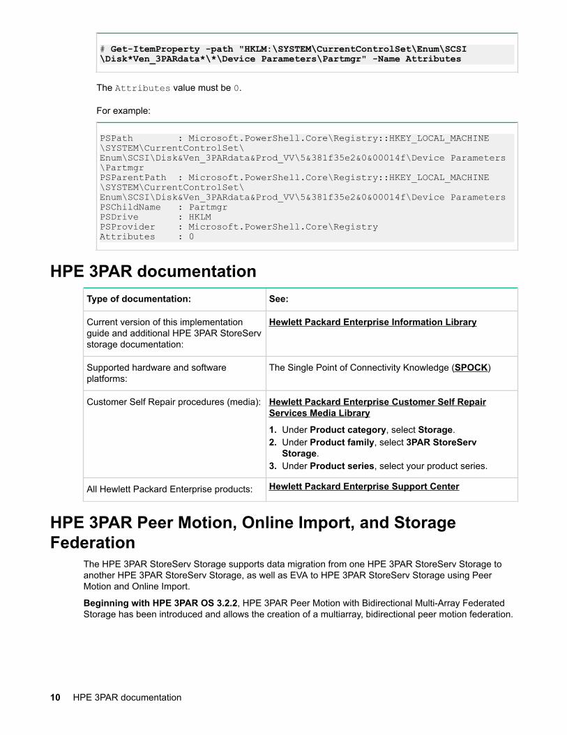
# Get-ItemProperty -path "HKLM:\SYSTEM\CurrentControlSet\Enum\SCSI\Disk*Ven_3PARdata*\*\Device Parameters\Partmgr" -Name Attributes
The Attributes value must be 0.
For example:
PSPath : Microsoft.PowerShell.Core\Registry::HKEY_LOCAL_MACHINE\SYSTEM\CurrentControlSet\Enum\SCSI\Disk&Ven_3PARdata&Prod_VV\5&381f35e2&0&00014f\Device Parameters\PartmgrPSParentPath : Microsoft.PowerShell.Core\Registry::HKEY_LOCAL_MACHINE\SYSTEM\CurrentControlSet\Enum\SCSI\Disk&Ven_3PARdata&Prod_VV\5&381f35e2&0&00014f\Device ParametersPSChildName : PartmgrPSDrive : HKLMPSProvider : Microsoft.PowerShell.Core\RegistryAttributes : 0
HPE 3PAR documentationType of documentation: See:
Current version of this implementationguide and additional HPE 3PAR StoreServstorage documentation:
Hewlett Packard Enterprise Information Library
Supported hardware and softwareplatforms:
The Single Point of Connectivity Knowledge (SPOCK)
Customer Self Repair procedures (media): Hewlett Packard Enterprise Customer Self RepairServices Media Library
1. Under Product category, select Storage.2. Under Product family, select 3PAR StoreServ
Storage.3. Under Product series, select your product series.
All Hewlett Packard Enterprise products: Hewlett Packard Enterprise Support Center
HPE 3PAR Peer Motion, Online Import, and StorageFederation
The HPE 3PAR StoreServ Storage supports data migration from one HPE 3PAR StoreServ Storage toanother HPE 3PAR StoreServ Storage, as well as EVA to HPE 3PAR StoreServ Storage using PeerMotion and Online Import.
Beginning with HPE 3PAR OS 3.2.2, HPE 3PAR Peer Motion with Bidirectional Multi-Array FederatedStorage has been introduced and allows the creation of a multiarray, bidirectional peer motion federation.
10 HPE 3PAR documentation
CAUTION:
Before performing Unidirectional or Bidirectional Peer Motion migrations, Path Verify Enabledneeds to be set in the MPIO settings on Windows Server 2016/2012/2008 configured hosts.
To configure the Path Verify Enabled MPIO setting:
• On Windows Server 2016/2012, the setting can be found at Device Manager > Disk Drives.Right-click any of the HPE 3PAR disks, select MPIO > MS DSM Details, and then select thePath Verify Enabled check box.
• On Windows Server 2008, the setting can be found at Server Manager > Disk Management.Right-click any of the HPE 3PAR disks, select MPIO > MS DSM Details, and then select thePath Verify Enabled check box.
For additional information about HPE 3PAR Peer Motion and HPE 3PAR Online Migration, see the HPE3PAR Peer Motion and HPE 3PAR Online Import User Guide at the Hewlett Packard EnterpriseInformation Library website.
More Informationhttp://www.hpe.com/info/storage/docs
HPE 3PAR Peer PersistenceHPE 3PAR Peer Persistence enables HPE 3PAR StoreServ Storage systems located at metropolitandistances to act as peers to each other, presenting a nearly continuous storage system to hosts andservers connected to them. This capability allows customers to configure a high-availability solutionbetween two sites or data centers, where switchover and switchback remain transparent to the hosts andapplications running on those hosts.
CAUTION:
Path Verify Enabled must be set in the MPIO settings on Windows Server 2016/2012/2008 hostsconfigured for an HPE 3PAR Peer Persistence implementation.
To configure the Path Verify Enabled MPIO setting:
• With Windows Server 2016/2012, the setting can be found at Device Manager > Disk Drives.Right-click any of the HPE 3PAR disks, select MPIO > MS DSM Details, and then select thePath Verify Enabled check box.
• With Windows Server 2008, the setting can be found at Server Manager > Disk Management.Right-click any of the HPE 3PAR disks, select MPIO > MS DSM Details, and then select thecheck box.
For additional information about HPE 3PAR Peer Persistence, see the following:
• HPE 3PAR Remote Copy Software User Guide at the Hewlett Packard Enterprise Information Librarywebsite.
• Technical white paper Implementing Microsoft multisite clustering using HPE 3PAR PeerPersistence (Hewlett Packard Enterprise document #4AA5-5894ENW) at the Hewlett PackardEnterprise Support Center website.
More Informationhttp://www.hpe.com/info/storage/docshttp://www.hpe.com/support/hpesc
HPE 3PAR Peer Persistence 11

Performing preliminary HPE 3PAR StoreServStorage and host configuration
NOTE:
Hewlett Packard Enterprise recommends using default values to configure your host unlessotherwise specified in the following procedures.
Required:
If you are setting up a fabric along with your installation of the HPE 3PAR StoreServ Storage, see Settingup and zoning the fabric—FC before configuring or connecting the HPE 3PAR StoreServ Storage andhost.
Configuring the HPE 3PAR StoreServ Storage hostpersona and ports
For an HPE 3PAR StoreServ Storage system, each HPE 3PAR StoreServ Storage port connecting to ahost HBA port through a fabric or direct connection must be set to the correct host persona.
NOTE:
When deploying HPE Virtual Connect Direct-attach FC Storage for HPE 3PAR StoreServ Storage,where the HPE 3PAR StoreServ Storage ports are cabled directly to the uplink ports on the VirtualConnect FlexFabric 10 Gb/24-port Module for c-Class BladeSystem, follow the steps for configuringthe HPE 3PAR StoreServ Storage ports for a fabric connection.
For more information about Virtual Connect, Virtual Connect interconnect modules, and the VirtualConnect direct-attach feature, see the Virtual Connect documentation available by searching theHewlett Packard Enterprise Support Center website.
See also the HPE SAN Design Reference Guide at the Storage Single Point of ConnectivityKnowledge (SPOCK) website.
More Informationhttp://www.hpe.com/support/hpeschttp://www.hpe.com/storage/spock
Configuring ports on the HPE 3PAR StoreServ Storage—direct connection—FC
A different FC array target port connection type is required depending on the HPE 3PAR OS version onthe array, the array target port type, and the speed of host FC adapter that will directly connect to thearray.
NOTE:
Support for direct connection to hosts using the 16 Gbps FC 3PAR StoreServ Storage target beginsat HPE 3PAR OS version 3.2.2 MU2.
To identify the type of array target port adapter, use the showport -par command and identify theMaxRate listed for the port planned for direct connect. For example, array target port 0:1:1 is listed as8Gbps and 2:1:1 as 16Gbps:
12 Performing preliminary HPE 3PAR StoreServ Storage and host configuration
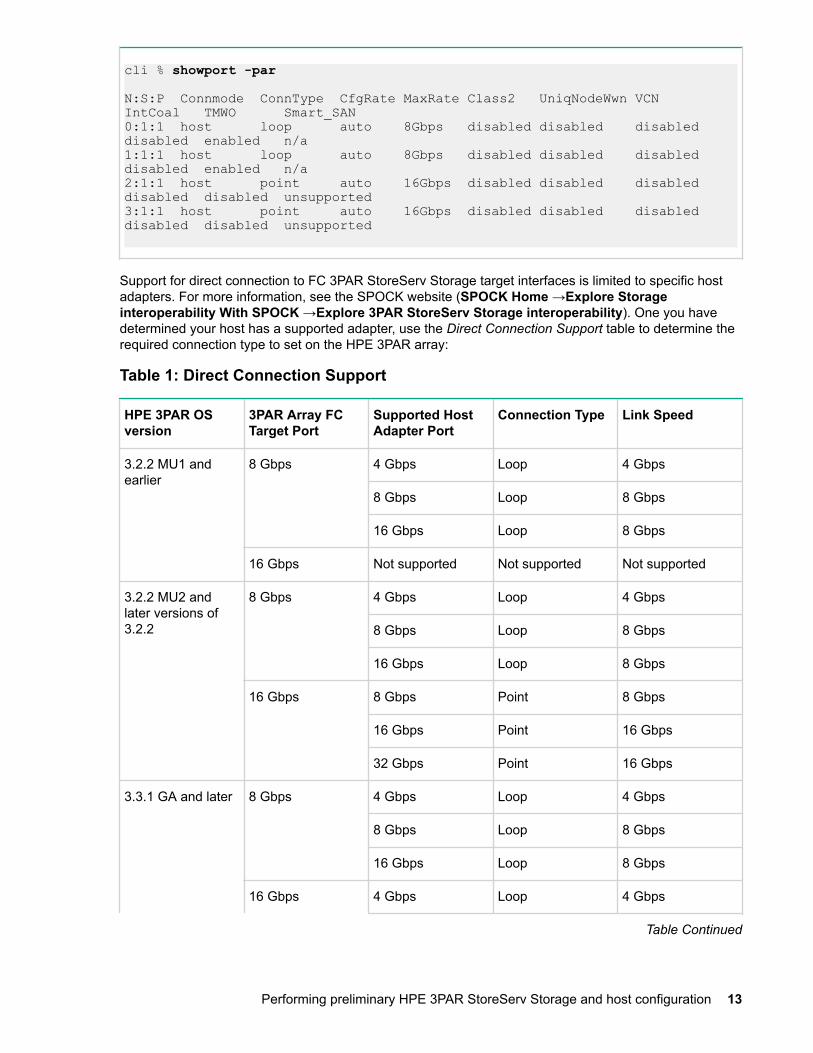
cli % showport -par
N:S:P Connmode ConnType CfgRate MaxRate Class2 UniqNodeWwn VCN IntCoal TMWO Smart_SAN0:1:1 host loop auto 8Gbps disabled disabled disabled disabled enabled n/a1:1:1 host loop auto 8Gbps disabled disabled disabled disabled enabled n/a2:1:1 host point auto 16Gbps disabled disabled disabled disabled disabled unsupported3:1:1 host point auto 16Gbps disabled disabled disabled disabled disabled unsupported
Support for direct connection to FC 3PAR StoreServ Storage target interfaces is limited to specific hostadapters. For more information, see the SPOCK website (SPOCK Home →Explore Storageinteroperability With SPOCK →Explore 3PAR StoreServ Storage interoperability). One you havedetermined your host has a supported adapter, use the Direct Connection Support table to determine therequired connection type to set on the HPE 3PAR array:
Table 1: Direct Connection Support
HPE 3PAR OSversion
3PAR Array FCTarget Port
Supported HostAdapter Port
Connection Type Link Speed
3.2.2 MU1 andearlier
8 Gbps 4 Gbps Loop 4 Gbps
8 Gbps Loop 8 Gbps
16 Gbps Loop 8 Gbps
16 Gbps Not supported Not supported Not supported
3.2.2 MU2 andlater versions of3.2.2
8 Gbps 4 Gbps Loop 4 Gbps
8 Gbps Loop 8 Gbps
16 Gbps Loop 8 Gbps
16 Gbps 8 Gbps Point 8 Gbps
16 Gbps Point 16 Gbps
32 Gbps Point 16 Gbps
3.3.1 GA and later 8 Gbps 4 Gbps Loop 4 Gbps
8 Gbps Loop 8 Gbps
16 Gbps Loop 8 Gbps
16 Gbps 4 Gbps Loop 4 Gbps
Table Continued
Performing preliminary HPE 3PAR StoreServ Storage and host configuration 13
HPE 3PAR OSversion
3PAR Array FCTarget Port
Supported HostAdapter Port
Connection Type Link Speed
8 Gbps Loop 8 Gbps
16 Gbps Point 16 Gbps
32 Gbps Point 16 Gbps
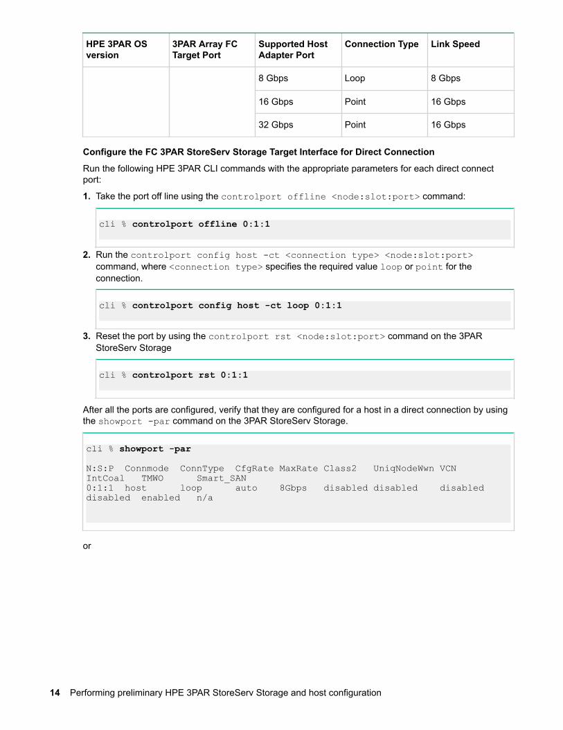
Configure the FC 3PAR StoreServ Storage Target Interface for Direct Connection
Run the following HPE 3PAR CLI commands with the appropriate parameters for each direct connectport:
1. Take the port off line using the controlport offline <node:slot:port> command:
cli % controlport offline 0:1:1
2. Run the controlport config host -ct <connection type> <node:slot:port>command, where <connection type> specifies the required value loop or point for theconnection.
cli % controlport config host -ct loop 0:1:1
3. Reset the port by using the controlport rst <node:slot:port> command on the 3PARStoreServ Storage
cli % controlport rst 0:1:1
After all the ports are configured, verify that they are configured for a host in a direct connection by usingthe showport -par command on the 3PAR StoreServ Storage.
cli % showport -par
N:S:P Connmode ConnType CfgRate MaxRate Class2 UniqNodeWwn VCN IntCoal TMWO Smart_SAN0:1:1 host loop auto 8Gbps disabled disabled disabled disabled enabled n/a
or
14 Performing preliminary HPE 3PAR StoreServ Storage and host configuration
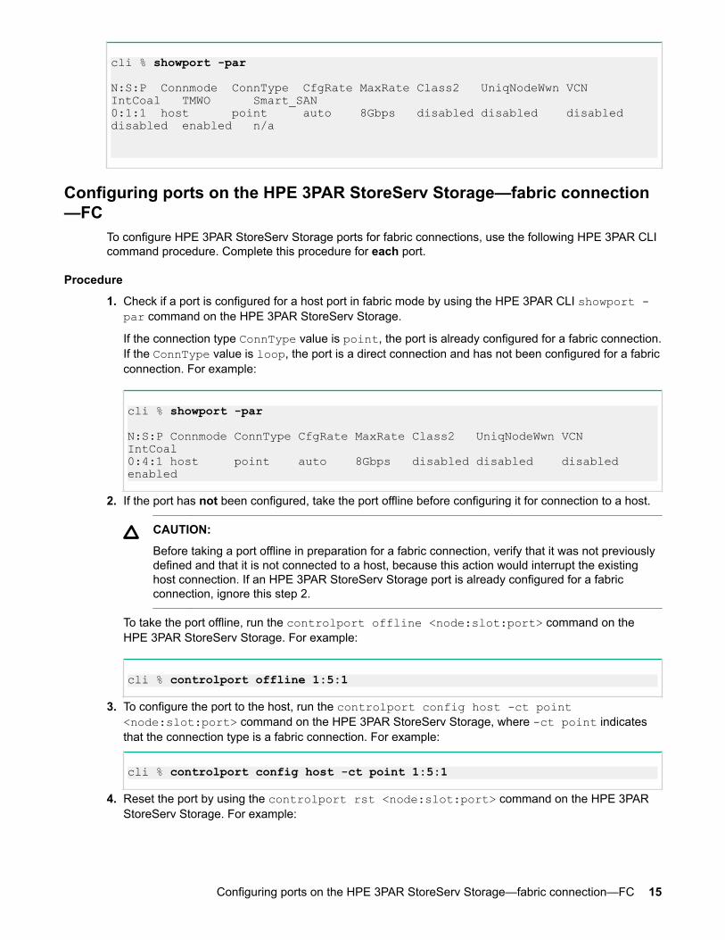
cli % showport -par
N:S:P Connmode ConnType CfgRate MaxRate Class2 UniqNodeWwn VCN IntCoal TMWO Smart_SAN0:1:1 host point auto 8Gbps disabled disabled disabled disabled enabled n/a
Configuring ports on the HPE 3PAR StoreServ Storage—fabric connection—FC
To configure HPE 3PAR StoreServ Storage ports for fabric connections, use the following HPE 3PAR CLIcommand procedure. Complete this procedure for each port.
Procedure
1. Check if a port is configured for a host port in fabric mode by using the HPE 3PAR CLI showport -par command on the HPE 3PAR StoreServ Storage.
If the connection type ConnType value is point, the port is already configured for a fabric connection.If the ConnType value is loop, the port is a direct connection and has not been configured for a fabricconnection. For example:
cli % showport -par
N:S:P Connmode ConnType CfgRate MaxRate Class2 UniqNodeWwn VCN IntCoal0:4:1 host point auto 8Gbps disabled disabled disabled enabled
2. If the port has not been configured, take the port offline before configuring it for connection to a host.
CAUTION:
Before taking a port offline in preparation for a fabric connection, verify that it was not previouslydefined and that it is not connected to a host, because this action would interrupt the existinghost connection. If an HPE 3PAR StoreServ Storage port is already configured for a fabricconnection, ignore this step 2.
To take the port offline, run the controlport offline <node:slot:port> command on theHPE 3PAR StoreServ Storage. For example:
cli % controlport offline 1:5:1
3. To configure the port to the host, run the controlport config host -ct point<node:slot:port> command on the HPE 3PAR StoreServ Storage, where -ct point indicatesthat the connection type is a fabric connection. For example:
cli % controlport config host -ct point 1:5:1
4. Reset the port by using the controlport rst <node:slot:port> command on the HPE 3PARStoreServ Storage. For example:
Configuring ports on the HPE 3PAR StoreServ Storage—fabric connection—FC 15

cli % controlport rst 1:5:1
5. Connect each host HBA port to the fabric. Associate the WWN of each host HBA port with the HPE3PAR StoreServ Storage port where it connects.
6. Complete the zoning using the procedure in Setting up and zoning the fabric—FC.7. To verify that the host has successfully connected to the HPE 3PAR StoreServ Storage, run the
showhost command on the HPE 3PAR StoreServ Storage.
Creating a host definition—FCBefore connecting the host to the HPE 3PAR StoreServ Storage, create a host definition for the WindowsServer 2016/2012/2008 hosts.
NOTE:
Before changing host personas, see the HPE 3PAR Operating System Upgrade Pre-Planning Guidefor instructions to prevent loss of LUN mapping available at the Hewlett Packard EnterpriseInformation Library website.
• With HPE 3PAR OS 3.2.1 and later, Hewlett Packard Enterprise requires host WindowsServerpersona 15 for Windows Server 2016.
• With HPE 3PAR OS 3.1.3 and later, Hewlett Packard Enterprise requires host WindowsServerpersona 15 for Windows Server 2008, Windows Server 2008 R2, Windows Server 2012, orWindows 2012 R2 hosts. However, host Generic-ALUA persona 2 is automatically assignedfollowing an online HPE 3PAR OS upgrade from OS version 3.1.2. After such an upgrade,change host Generic-ALUA persona 2 to host WindowsServer persona 15.
The host WindowsServer persona 15 includes all the functionality of hostGeneric-ALUApersona 2 as well as a fix for an issue where a Windows Server will mark the HPE 3PAR LUNsoffline following an HPE 3PAR OS upgrade.
• With HPE 3PAR OS 3.1.2, Hewlett Packard Enterprise requires host Generic-ALUA persona 2for Windows Server 2008, Windows Server 2008 R2, Windows Server 2012, or Windows 2012R2 hosts. Following an online upgrade from HPE 3PAR OS 3.1.1 for Windows Server 2008 R2hosts, change from host Generic persona 1 to host Generic-ALUA persona 2.
• With HPE 3PAR OS 3.1.1, Hewlett Packard Enterprise requires host Generic persona 1 forWindows Server 2008 R2 (only) and host Generic-ALUA persona 2 for Windows Server 2008,Windows Server 2012/2008, or Windows Server 2012/2008 Windows Server 2008 R2 hosts.
Host persona 2 enables the following functional features:
◦ The UARepLun notifies the host of newly exported VLUNs and must trigger a LUN discoveryrequest on the host, making the VLUN automatically available on format.
◦ The RTPG feature automatically enables active/active multipathing on the following hosts:
– Windows Server 2008– Windows Server 2008 R2– Windows Server 2012– Windows Server 2012 R2
Procedure
1. Create host definitions by using the createhost [options] <hostname> [<WWN>...]command. For example:
cli % createhost -persona 15 windowshost 10000000C9606724
2. Verify that the host was created by using the showhost command.
16 Creating a host definition—FC

cli% showhost
Id Name Persona -WWN/iSCSI_Name- Port 0 windowshost WindowsServer 10000000C9606724 ---
More Informationhttp://www.hpe.com/info/storage/docs
Changing host persona 2 to persona 15—HPE 3PAR CLIThe change to host WindowsServer persona 15 is an online procedure.
Procedure
1. Use the HPE 3PAR CLI sethost command to change the persona and verify the change using theshowhost command.
# sethost -persona 15 windowshost# showhost
Id Name Persona -WWN/iSCSI_Name- Port0 windowshost WindowsServer 10000000C9606724 0:5:1 10000000C9606724 1:5:1
Changing host persona 6 or persona 1 to persona 2—HPE 3PAR CLIThe change to host Generic-ALUA persona 2 is an offline procedure.
Procedure
1. Stop all host I/O on the Windows Server 2008 or Windows Server 2008 R2 host.2. Shut down the host.3. Issue the showhost command. Make sure that no active paths are shown.4. To change the persona, issue the HPE 3PAR CLI sethost command.5. To verify the setting, issue the HPE 3PAR CLI showhost command.
# sethost -persona 2 windowshostshowhost
Id Name Persona -WWN/iSCSI_Name- Port0 windowshost Generic-ALUA 10000000C9606724 ---
6. Turn on the Windows Server. The host enables ALUA on all the LUN paths when it boots.
Setting up multipathing—FC• With Windows Server 2016, Hewlett Packard Enterprise supports the following multipath solution:
◦ Windows MPIO• With Windows Server 2012/2008, Hewlett Packard Enterprise supports the following multipath
solutions:
◦ Windows MPIO◦ Veritas DMP/Veritas Infoscale Enterprise (Storage)
Changing host persona 2 to persona 15—HPE 3PAR CLI 17

For high-availability storage with load balancing of I/O and improved system and application performance,Windows Server 2012/2008 requires the native Microsoft MPIO and the StorPort miniport driver.
Configuring Microsoft MPIOFor a list of the prerequisite Microsoft hot fixes, see the SPOCK website. For more information about thespecific hot fixes listed on the SPOCK website, see the Microsoft website.
Procedure
1. If you have not already done so, check the HBA vendor documentation for required support drivers,and install them.
2. If necessary, install the StorPort miniport driver.3. If the MPIO feature is not enabled, open the server manager and install the MPIO feature. This action
requires a restart.4. After restarting, open the Windows Administrative Tools and click MPIO.5. In the MPIO-ed Devices tab, click Add and the Add MPIO Support popup appears.6. In the Device Hardware ID: text box, enter 3PARdataVV, and then click OK.
7. Restart as directed.
NOTE:
You can also use the MPIO CLI to add 3PARdataVV using the following command: mpclaim -r -I -d "3PARdataVV"
More Informationhttp://www.hpe.com/storage/spock
18 Configuring Microsoft MPIO
http://support.microsoft.com
Setting up and zoning the fabric—FCNOTE: This topic does not apply when deploying Virtual Connect Direct-Attach Fibre Channel forHPE 3PAR StoreServ Storage systems, where the HPE 3PAR StoreServ Storage ports are cableddirectly to the uplink ports on either the Virtual Connect FlexFabric 10 Gb/24-port Module for c-ClassBladeSystem or Virtual Connect FlexFabric 20/40 F8 Module for c-Class BladeSystem. Zoning isautomatically configured based on the Virtual Connect SAN Fabric and server profile definitions.
For more information about Virtual Connect, Virtual Connect interconnect modules, and the VirtualConnect Direct-Attach Fibre Channel feature, see the Hewlett Packard Enterprise Support Centerwebsite.
See also the HPE SAN Design Reference Guide at the SPOCK website (SPOCK Home > DesignGuides > SAN Design Guide).
Fabric zoning controls which FC end-devices have access to each other on the fabric. Zoning alsoisolates the host and HPE 3PAR StoreServ Storage ports from Registered State Change Notifications(RSCNs) that are irrelevant to these ports.
Set up fabric zoning by associating the device WWNs or the switch ports with specified zones in thefabric. Using the WWN method or HPE Smart SAN zoning is recommended with the HPE 3PARStoreServ Storage. These zoning methods allow the zone to survive changing of switch ports whencables are moved around on a fabric and are also compatible with Persistent Port feature. PORT zoningor Hard zoning is not recommended as it is not compatible with Persistent Port Feature.
Required:
Employ fabric zoning, by using the methods provided by the switch vendor, to create relationshipsbetween host HBA/CNA ports and HPE 3PAR StoreServ Storage ports before connecting the hostHBA/CNA ports or HPE 3PAR StoreServ Storage ports to the fabrics.
FC switch vendors support the zoning of the fabric end-devices in different zoning configurations. Thereare advantages and disadvantages with each zoning configuration, so determine what is needed beforechoosing a zoning configuration.
For configuring HP FlexFabric 5900 switch settings for FCoE Host - FC Storage connections refer to HPNetworking Single-Tier FC/FCoE Solution using HP Rack Servers and HP Storage.
The HPE 3PAR StoreServ Storage arrays support the following zoning configurations:
• One initiator to one target per zone• One initiator to multiple targets per zone (zoning by HBA). This zoning configuration is recommended
for the HPE 3PAR StoreServ Storage. Zoning by HBA is required for coexistence with other HewlettPackard Enterprise storage systems.
NOTE:
◦ For high availability and clustered environments that require multiple initiators to access thesame set of target ports, Hewlett Packard Enterprise recommends creating separate zonesfor each initiator with the same set of target ports.
◦ The storage targets in the zone can be from the same HPE 3PAR StoreServ Storage, multipleHPE 3PAR StoreServ Storage systems, or a mixture of HPE 3PAR and other HewlettPackard Enterprise storage systems.
For more information about using one initiator to multiple targets per zone, see the HPE SAN DesignReference Guide at the SPOCK website (SPOCK Home > Design Guides > SAN Design Guide).
When using an unsupported zoning configuration and an issue occurs, Hewlett Packard Enterprise mightrequire implementing one of the supported zoning configurations as part of the corrective action.
Setting up and zoning the fabric—FC 19
Verify the switch and zone configurations by using the HPE 3PAR CLI showhost command. Verify thateach initiator is zoned with the correct targets after completing the following tasks:
• Complete configuration of the storage port to the host and connect to the switch.• Create a zone configuration on the switch following the HPE SAN Design Reference Guide and enable
the zone set configuration.• Use the showhost command to verify that the host is seen on the storage node.
More Informationhttp://www.hpe.com/support/hpeschttp://www.hpe.com/storage/spock
HPE Smart SAN for 3PAR—FCHPE 3PAR OS 3.2.2 HPE Smart SAN feature on 16 Gb FC targets began with HPE 3PAR OS 3.2.2. Thefollowing HPE 3PAR StoreServ Storage systems support this feature:
• HPE 3PAR StoreServ 20000 Storage• HPE 3PAR StoreServ 10000 Storage• HPE 3PAR StoreServ 9000 Storage• HPE 3PAR StoreServ 8000 Storage• HPE 3PAR StoreServ 7000 Storage
HPE Smart SAN for 3PAR through its TDPZ (target-driven peer zoning) feature enables customers toautomate peer zoning, which results in the creation of fewer zones and enables configuration of zones inminutes. Through automation, it reduces the probability of errors and potential downtime. WithoutHPE Smart SAN for 3PAR, an administrator must preconfigure zones on the FC switch, beforeconfiguring hosts and VLUNs on the HPE 3PAR StoreServ Storage. With HPE Smart SAN for 3PAR, theadministrator can configure and control zoning directly from the HPE 3PAR CLI.
Beginning with HPE 3PAR OS 3.3.1, HPE Smart SAN for 3PAR 2.0 is supported. With HPE Smart SANfor 3PAR 2.0, the target ports support device registration on the fabric using the FDMI (Fabric DeviceManagement Interface) Protocol. The switch CLI command can be used to display the FDMI datacontaining Target Port Management information. Additional Smart SAN HBA attributes are only registeredwith Smart SAN capable switches.
For information about supported FC switches and their firmware revisions with HPE Smart SAN for 3PAR,see the SPOCK website.
For more information about HPE Smart SAN for 3PAR, including configuration, see the HPE Smart SANfor 3PAR 2.0 User Guide at the Hewlett Packard Enterprise Information Library website.
More Informationhttp://www.hpe.com/storage/spockhttp://www.hpe.com/info/storage/docs
HPE 3PAR coexistenceThe HPE 3PAR StoreServ Storage can coexist with other Hewlett Packard Enterprise storage systemarray families.
For supported Hewlett Packard Enterprise storage system combinations and rules, see the HPE SANDesign Reference Guide at the SPOCK website (SPOCK Home > Design Guides > SAN DesignGuide).
More Informationhttp://www.hpe.com/storage/spock
20 HPE Smart SAN for 3PAR—FC

Configuration guidelines for switch vendors—FCUse the following FC switch vendor guidelines before configuring ports on fabrics to which the HPE 3PARStoreServ Storage connects.
• Brocade switch ports that connect to a host HBA port or to an HPE 3PAR StoreServ Storage port mustbe set to their default mode. On Brocade 3xxx switches running Brocade firmware 3.0.2 or later, verifythat each switch port is in the correct mode by using the Brocade telnet interface and theportcfgshow command, as follows:
brocade2_1:admin> portcfgshow
Ports 0 1 2 3 4 5 6 7-----------------+--+--+--+--+----+--+--+--Speed AN AN AN AN AN AN AN AN Trunk Port ON ON ON ON ON ON ON ON Locked L_Port .. .. .. .. .. .. .. .. Locked G_Port .. .. .. .. .. .. .. .. Disabled E_Port .. .. .. .. .. .. .. .. where AN:AutoNegotiate, ..:OFF, ??:INVALID.
The following fill-word modes are supported on a Brocade 8 Gb switch running FOS firmware 6.3.1aand later:
admin>portcfgfillword
Usage: portCfgFillWord PortNumber Mode [Passive]Mode: 0/-idle-idle - IDLE in Link Init, IDLE as fill word (default) 1/-arbff-arbff - ARBFF in Link Init, ARBFF as fill word 2/-idle-arbff - IDLE in Link Init, ARBFF as fill word (SW) 3/-aa-then-ia - If ARBFF/ARBFF failed, then do IDLE/ARBFF
Hewlett Packard Enterprise recommends setting the fill word to mode 3 (aa-then-ia), which is thepreferred mode, by using the portcfgfillword command. If the fill word is not correctly set,er_bad_os counters (invalid ordered set) will increase when using the portstatsshow commandwhile connected to 8 Gb HBA ports, as they need the ARBFF-ARBFF fill word. Mode 3 will also workcorrectly for lower-speed HBAs, such as 4 Gb/2 Gb HBAs. For more information, see the Fabric OSCommand Reference Manual and the FOS release notes, at the Brocade website.
NOTE:
In addition, some Hewlett Packard Enterprise switches, such as the HPE SN8000B 8-slot SANbackbone director switch, the HPE SN8000B 4-slot SAN director switch, the HPE SN6000B 16Gb FC switch, or the HPE SN3000B 16 Gb FC switch automatically select the proper fill-wordmode 3 as the default setting.
• McDATA switch or director ports must be in their default modes as G or GX-port (depending on theswitch model), with their speed setting permitting them to autonegotiate.
• Cisco switch ports that connect to HPE 3PAR StoreServ Storage ports or host HBA ports must be setto AdminMode = FX and AdminSpeed = auto port, with the speed set to auto negotiate.
• QLogic switch ports must be set to port type GL-port and port speed auto-detect. QLogic switch portsthat connect to the HPE 3PAR StoreServ Storage must be set to I/O Stream Guard disable or auto,but never enable.
More Informationhttp://www.brocade.com/en.html
Configuration guidelines for switch vendors—FC 21

Target port limits and specifications—FCTo avoid overwhelming a target port and to ensure continuous I/O operations, observe the followinglimitations on a target port:
• Follow the instructions for setting the maximum number of initiator connections supported per arrayport, per array node pair, and per array as shown in the HPE 3PAR Support Matrix documentation atthe SPOCK website (SPOCK Home > Other Hardware > 3PAR).
• Maximum I/O queue depth per port on each HPE 3PAR StoreServ Storage HBA model, as follows:
HBA Protocol Array Bus Speed Ports Max. QueueDepth
EmulexLP11002
FC HPE F200,F400, T400,T800
PCI-X 4 Gbps 2 959
HPE 3PARFC044X
FC HPE F200,F400, T400,T800
PCI-X 4 Gbps 4 1638
EmulexLPe12002
FC HPE 3PARStoreServ
7000
PCIe 8 Gbps 2 3276
EmulexLPe12004
FC HPE 3PARStoreServ
7000, 10000
PCIe 8 Gbps 4 3276
EmulexLPe16002
FC HPE 3PARStoreServ
7000, 8000,10000
PCIe 16 Gbps 2 3072
EmulexLPe16004
FC HPE 3PARStoreServ
8000, 9000,20000
PCIe 16 Gbps 4 3072
• The I/O queues are shared among the connected host HBA ports on a first-come, first-served basis.• When all queues are in use and a host HBA port tries to initiate I/O, it receives a target queue full
response from the HPE 3PAR StoreServ Storage port. This condition can result in erratic I/Operformance on each host. If this condition occurs, each host should be throttled so that it cannotoverrun the HPE 3PAR StoreServ Storage port's queues when all hosts are delivering their maximumnumber of I/O requests.
22 Target port limits and specifications—FC

NOTE:
◦ With HPE 3PAR OS 3.3.1 and later, HPE 3PAR has implemented Multi-Queue processing forthe 16 Gb FC target adapter. This action allows for balanced CPU utilization and improvesperformance.
◦ When host ports can access multiple targets on fabric zones, the target number assigned bythe host driver for each discovered target can change when the host is booted and sometargets are not present in the zone. This situation might change the device node access pointfor devices during a host restart. This issue can occur with any fabric-connected storage, andis not specific to the HPE 3PAR StoreServ Storage.
◦ The maximum number of I/O paths supported is 16.
More Informationhttp://www.hpe.com/storage/spock
HPE 3PAR Priority Optimization—FCStarting with HPE 3PAR OS 3.1.2 MU2, the HPE 3PAR Priority Optimization feature was introduced.This feature is a more efficient and dynamic solution for managing server workloads and can be used asan alternative to setting host I/O throttles. When using this feature, a storage administrator is able toshare storage resources more effectively by enforcing quality-of-service limits on the array.
NOTE:
It has been noticed that Windows may offline the device/LUN if the bandwidth QoS rule on theVVset that the device/LUN belongs to is too aggressive. If this is the case, you need to decrease thebandwidth QoS rule.
No special settings are needed on the host side to obtain the benefit of HPE 3PAR Priority Optimization.However, certain per target or per-adapter throttle settings might need to be adjusted in rare cases.
For complete details of how to use HPE 3PAR Priority Optimization (Quality of Service) on HPE 3PARStoreServ Storage, see the HPE 3PAR Priority Optimization technical whitepaper.
More Informationhttp://www.hpe.com/info/3PAR-Priority-Optimization
HPE 3PAR Persistent Ports—FCThe HPE 3PAR Persistent Ports (or virtual ports) feature minimizes I/O disruption during a HPE 3PARStoreServ Storage online upgrade or node-down event. Port shutdown or reset events do not trigger thisfeature.
Each FC target storage array port has a partner array port automatically assigned by the system. Partnerports are assigned across array node pairs.
HPE 3PAR Persistent Ports allows a HPE 3PAR StoreServ Storage FC port to assume the identity of afailed port (WWN port) while retaining its own identity. Where a given physical port assumes the identity ofits partner port, the assumed port is designated as a persistent port. Array port failover and failback withHPE 3PAR Persistent Ports is transparent to most host-based multipathing software, which can keep allof its I/O paths active.
NOTE:
Use of HPE 3PAR Persistent Ports technology does not negate the need for properly installed,configured, and maintained host multipathing software.
For a more complete description of the HPE 3PAR Persistent Ports feature, its operation, and a completelist of required setup and connectivity guidelines, see the following documents:
HPE 3PAR Priority Optimization—FC 23
• Technical whitepaper HPE 3PAR StoreServ Persistent Ports (Hewlett Packard Enterprise document#F4AA4-4545ENW) at the Hewlett Packard Enterprise Support Center website.
• HPE 3PAR Command Line Interface Administrator’s Manual in the "Using Persistent Ports forNondisruptive Online Software Upgrades" topic at the Hewlett Packard Enterprise Information Librarywebsite.
More Informationhttp://www.hpe.com/support/hpeschttp://www.hpe.com/info/storage/docs
HPE 3PAR Persistent Ports setup and connectivity guidelines—FCBeginning with HPE 3PAR OS 3.1.2, the HPE 3PAR Persistent Ports feature is supported for FC targetports.
Beginning with HPE 3PAR OS 3.1.3, the HPE 3PAR Persistent Port feature has additional functionalityto minimize I/O disruption during an array port loss_sync event triggered by a loss of array portconnectivity to the fabric.
Follow the specific cabling setup and connectivity guidelines so that HPE 3PAR Persistent Ports functionproperly:
• HPE 3PAR StoreServ Storage FC partner ports must be connected to the same FC fabric, andpreferably to different FC switches on the fabric.
• The FC fabric must support NPIV, and NPIV must be enabled.• Configure the host-facing HBAs for point-to-point fabric connection (there is no support for direct-
connect "loops").
For information regarding the HPE 3PAR Persistent Ports feature for an FCoE initiator to FC targetconfiguration (FCoE to FC switched), see Setting up a Windows Server 2016/2012/2008 HPE 3PARStoreServ Storage configuration—FC on page 30.
HPE 3PAR Persistent Checksum—FCThe HPE 3PAR Persistent Checksum feature, available on HPE 3PAR StoreServ 20000 and 8000Storage systems (arrays), provides end-to-end data integrity protection from the host initiator HBAthrough the data network to the backend drives on the HPE StoreServ Storage. This feature is based onthe DIF protection model defined by the SCSI T10 committee. It provides data protection from silent datacorruption of any media and transmission errors caused by any component in the I/O stack across thedata network. Detection and recovery features have been built into the HPE 3PAR OS to correct issuesdiscovered through this feature.
Minimum host HBA driver versions for support of HPE 3PAR Persistent Checksum over FC are required.With these drivers, the HPE 3PAR Persistent Checksum on HPE 3PAR StoreServ Storage is enabled bydefault, and there is no need to configure anything on the array or the host HBA driver.
For supported HBAs, driver version, and supported host OSs that support HPE 3PAR PersistentChecksum (DIF capable), see SPOCK website.
For additional information on the HPE 3PAR Persistent Checksum, see the HPE 3PAR StoreServArchitecture technical whitepaper at the Hewlett Packard Enterprise Information Library website.
More Informationhttp://www.hpe.com/storage/spockhttp://www.hpe.com/info/storage/docs
24 HPE 3PAR Persistent Ports setup and connectivity guidelines—FC
HPE 3PAR Express Writes—FCWith HPE 3PAR OS 3.2.x and later, the HPE 3PAR Express Writes feature is enabled by default with 8Gb FC target ports in Host HBA mode with bit Express Write.
The HPE 3PAR Express Writes feature optimizes the performance for small block random writes.HPE 3PAR StoreServ Storage handles Express Write based on the I/O size and does not require anychanges in the host driver or kernel parameters.
NOTE:
For HPE 3PAR StoreServ Storage systems with 16 Gb FC target ports, the HPE 3PAR ExpressWrites feature is not supported.
HPE 3PAR Express Writes—FC 25

Configuring the HPE 3PAR StoreServ Storage—FCoE
FCoE target support was added in HPE 3PAR OS 3.1.3.
NOTE:
Hewlett Packard Enterprise recommends using default values to configure your host unlessotherwise specified in the following procedures.
VLAN configuration and routing setupSwitch VLAN configuration and routing setup and configuration are beyond the scope of this document.See your switch manufacturer's guide for instructions about setting up VLANs and routing.
The HPE 3PAR StoreServ Storage arrays support the following VLAN configurations:
• One initiator to one target per VLAN• One initiator to multiple targets per VLAN• Multiple initiators to one target per VLAN• Multiple initiators to multiple targets per VLAN
Setting up the switch, initiator, and target ports—FCoEConnect the Windows host FCoE initiator ports and the HPE 3PAR StoreServ Storage FCoE target portsto the FCoE switches.
IMPORTANT:
For HPE 3PAR StoreServ 20000 and 8000 Storage systems, step 1 and step 2 are not required.Skip these steps and proceed to step 3.
Procedure
1. CNA ports on HPE 3PAR StoreServ 10000 and 7000 Storage systems require a one-timeconfiguration. For example, on a new FCoE configuration:
# showportN:S:P Mode State ----Node_WWN---- -Port_WWN/HW_Addr- Type Protocol0:3:1 suspended config_wait - - cna -0:3:2 suspended config_wait - - cna -
# showportN:S:P Brand Model Rev Firmware Serial HWType0:3:1 QLOGIC QLE8242 58 0.0.0.0 PCGLT0ARC1K3U4 CNA0:3:2 QLOGIC QLE8242 58 0.0.0.0 PCGLT0ARC1K3U4 CNA
2. If State=config_wait or Firmware=0.0.0.0, use the controlport config fcoe <n:s:p>command to configure.
# controlport config fcoe 0:3:1# controlport config fcoe 0:3:2
26 Configuring the HPE 3PAR StoreServ Storage—FCoE
Use the showport and showport -i commands to verify the configuration setting.
# showport 0:3:1 0:3:2N:S:P Mode State ----Node_WWN---- -Port_WWN/HW_Addr- Type Protocol LabelPartner FailoverState0:3:1 target ready 2FF70002AC000121 20310002AC000121 host FCoE -- -0:3:2 target ready 2FF70002AC000121 20320002AC000121 free FCoE -- -# showport -i 0:3:1 0:3:2N:S:P Brand Model Rev Firmware Serial HWType0:3:1 QLOGIC QLE8242 58 4.11.122 PCGLT0ARC1K3U4 CNA0:3:2 QLOGIC QLE8242 58 4.11.122 PCGLT0ARC1K3U4 CNA
3. Check the current settings of the FCoE ports using the showport -fcoe command:
# showport -fcoe
N:S:P ENode_MAC_Address PFC_Mask0:3:1 00-02-AC-07-01-21 0x080:3:2 00-02-AC-06-01-21 0x00
NOTE:
If you are changing the configuration from iSCSI to FCoE, follow the following steps.
a. Use the showport command:
# showport0:3:1 target ready - 000E1E05BEE6 iscsi iSCSI - - -0:3:2 target ready - 000E1E05BEE2 iscsi iSCSI - - -
Use the showport and showport -i commands to verify the configuration setting:
# showport 0:3:1 0:3:2N:S:P Mode State ----Node_WWN---- -Port_WWN/HW_Addr- Type Protocol LabelPartner FailoverState0:3:1 target ready 2FF70002AC000121 20310002AC000121 host FCoE -- -0:3:2 target ready 2FF70002AC000121 20320002AC000121 free FCoE -- -# showport -i 0:3:1 0:3:2N:S:P Brand Model Rev Firmware Serial HWType0:3:1 QLOGIC QLE8242 58 4.11.122 PCGLT0ARC1K3U4 CNA0:3:2 QLOGIC QLE8242 58 4.11.122 PCGLT0ARC1K3U4 CNA
b. Take the iSCSI ports offline using the controlport offline <node:slot:port> command:
# controlport offline 0:3:1# controlport offline 0:3:2
To verify that the ports are offline, issue the showport command:
Configuring the HPE 3PAR StoreServ Storage—FCoE 27
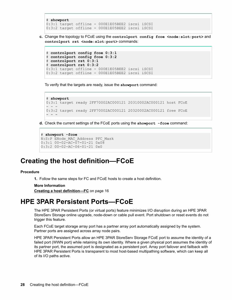
# showport0:3:1 target offline - 000E1E05BEE2 iscsi iSCSI0:3:2 target offline - 000E1E05BEE2 iscsi iSCSI
c. Change the topology to FCoE using the controlport config fcoe <node:slot:port> andcontrolport rst <node:slot:port> commands:
# controlport config fcoe 0:3:1# controlport config fcoe 0:3:2# controlport rst 0:3:1# controlport rst 0:3:20:3:1 target offline - 000E1E05BEE2 iscsi iSCSI0:3:2 target offline - 000E1E05BEE2 iscsi iSCSI
To verify that the targets are ready, issue the showport command:
# showport0:3:1 target ready 2FF70002AC000121 20310002AC000121 host FCoE- - -0:3:2 target ready 2FF70002AC000121 20320002AC000121 free FCoE- - -
d. Check the current settings of the FCoE ports using the showport -fcoe command:
# showport -fcoeN:S:P ENode_MAC_Address PFC_Mask0:3:1 00-02-AC-07-01-21 0x080:3:2 00-02-AC-06-01-21 0x0
Creating the host definition—FCoEProcedure
1. Follow the same steps for FC and FCoE hosts to create a host definition.
More InformationCreating a host definition—FC on page 16
HPE 3PAR Persistent Ports—FCoEThe HPE 3PAR Persistent Ports (or virtual ports) feature minimizes I/O disruption during an HPE 3PARStoreServ Storage online upgrade, node-down or cable pull event. Port shutdown or reset events do nottrigger this feature.
Each FCoE target storage array port has a partner array port automatically assigned by the system.Partner ports are assigned across array node pairs.
HPE 3PAR Persistent Ports allow an HPE 3PAR StoreServ Storage FCoE port to assume the identity of afailed port (WWN port) while retaining its own identity. Where a given physical port assumes the identity ofits partner port, the assumed port is designated as a persistent port. Array port failover and failback withHPE 3PAR Persistent Ports is transparent to most host-based multipathing software, which can keep allof its I/O paths active.
28 Creating the host definition—FCoE

NOTE:
Use of HPE 3PAR Persistent Ports technology does not negate the need for properly installed,configured, and maintained host multipathing software.
For a more complete description of the HPE 3PAR Persistent Ports feature, its operation, and a completelist of required setup and connectivity guidelines, see the following documents:
• Technical white paper HPE 3PAR StoreServ Persistent Ports (Hewlett Packard Enterprise document#F4AA4-4545ENW) at the Hewlett Packard Enterprise Support Center website.
• HPE 3PAR Command Line Interface Administrator’s Manual in the "Using Persistent Ports forNondisruptive Online Software Upgrades" topic at the Hewlett Packard Enterprise Information Librarywebsite.
More Informationhttp://www.hpe.com/support/hpeschttp://www.hpe.com/info/storage/docs
HPE 3PAR Persistent Ports setup and connectivity guidelines—FCoEBeginning with HPE 3PAR OS 3.1.3:
• The HPE 3PAR Persistent Ports feature is supported for FCoE target ports (FCoE end-to-endconfigurations).
• The HPE 3PAR Persistent Ports feature is enabled by default for HPE 3PAR StoreServ Storage FCoEports during node-down events.
Follow the specific cabling setup and connectivity guidelines for HPE 3PAR Persistent Ports tofunction properly. Key elements for the HPE 3PAR Persistent Ports feature setup and connectivityare:
• HPE 3PAR StoreServ Storage FCoE partner ports must be connected to the same FCoE network.• The same CNA port on host-facing HBAs in the nodes of a node pair must be connected to the same
FCoE network, and preferably to different FCoE switches on the network.• The FCoE network must support NPIV, and NPIV must be enabled.
HPE 3PAR Persistent Ports setup and connectivity guidelines—FCoE 29
Setting up a Windows Server 2016/2012/2008HPE 3PAR StoreServ Storage configuration—FC
Checking the host for required driversSee the Microsoft website for any required packages, hotfixes, or updated drivers. See the SPOCKwebsite for supported drivers, and follow HBA vendor instructions.
You can also use the Emulex One Command or QLogic QConvergeConsole software to verify support forHBA driver versions.
More Informationhttp://www.hpe.com/info/storage/docs
Installing and configuring an Emulex HBA—FCFor HBA installation instructions, driver support and usage guidelines, see the Emulex installation andusage guide for each product type. If your configuration includes MPIO, check also for information aboutany required MPIO support driver.
NOTE:
For booting from the HPE 3PAR StoreServ Storage, configuring the BIOS is required.
More InformationConfiguring for an HPE 3PAR StoreServ Storage boot—Emulex HBA on page 75
Configuring the Emulex support driverAfter installing the driver, set HBA driver parameters; consult the HBA driver documentation for details.
To avoid overwhelming a target port and to ensure continuous I/O operations, observe the limitations on atarget port; see Target port limits and specifications—iSCSI.
NOTE: When host ports can access multiple targets on fabric zones, the assigned target number(as assigned by the host driver) for each discovered target can change when the host is booted andsome targets are not present in the zone. This situation might change the device node access pointfor devices during a host restart. This issue can occur with any fabric-connected storage, and is notspecific to the HPE 3PAR StoreServ Storage.
If you run HPE 3PAR OS Online Upgrade, see the HPE 3PAR Upgrade Pre-Planning Guide in theReference section of the Hewlett Packard Enterprise Information Library website.
More InformationTarget port limits and specifications—FC on page 22http://www.hpe.com/info/storage/docs
30 Setting up a Windows Server 2016/2012/2008 HPE 3PAR StoreServ Storage configuration—FC

Checking Emulex HBA parameters and connection status
Procedure
1. Check the connection status using the Emulex One Command utility.2. Check the parameters.
Installing and configuring a QLogic HBA—FCFor HBA installation instructions, driver support and usage guidelines, see the QLogic installation andusage guide for each product type. If your configuration includes MPIO, check also for information aboutany required MPIO support driver.
NOTE:
For booting from the HPE 3PAR StoreServ Storage, configuring the BIOS is required.
More InformationConfiguring for an HPE 3PAR StoreServ Storage boot—QLogic HBA on page 75
Configuring the QLogic support driverAfter installing the driver, set HBA driver parameters, such as maximum number of LUNs per target andthe Port Down Retry Count; consult the HBA driver documentation for details.
To avoid overwhelming a target port and to ensure continuous I/O operations, observe the limitations on atarget port; see Target port limits and specifications—FC.
NOTE:
• When host ports can access multiple targets on fabric zones, the target number assigned by thehost driver for each discovered target can change when the host is booted and some targets arenot present in the zone. This action may change the device node access point for devices duringa host restart. This issue can occur with any fabric-connected storage, and is not specific to theHPE 3PAR StoreServ Storage.
• If you perform a HPE 3PAR OS Rolling Upgrade, see the HPE 3PAR Operating System UpgradePlanning Guide at the Hewlett Packard Enterprise Information Library website.
More InformationTarget port limits and specifications—FC on page 22http://www.hpe.com/info/storage/docs
Checking QLogic HBA parameters and connection statusUse the QLogic QConvergeConsole software to check connection status.
Installing and configuring a Brocade HBA—FCFor HBA installation instructions, driver support, and usage guidelines, see the Brocade installation andusage guide for each product type.
If your configuration includes MPIO, also check for information about required MPIO support drivers.
Checking Emulex HBA parameters and connection status 31

Configuring the Brocade support driver
Prerequisites
Install the driver.
Procedure
1. Set HBA driver parameters.
See the HBA driver documentation for details.
To avoid overwhelming a target port and to ensure continuous I/O operations, observe the limitationson a target port.
When host ports can access multiple targets on fabric zones, the assigned target number (as assignedby the host driver) for each discovered target can change when the host is booted and some targetsare not present in the zone. This situation might change the device node access point for devicesduring a host restart. This issue can occur with any fabric-connected storage, and is not specific to theHPE 3PAR StoreServ Storage.
If you perform an HPE 3PAR OS rolling upgrade, see the HPE 3PAR Operating System UpgradePlanning Guide at the Hewlett Packard Enterprise Information Library website.
More InformationTarget port limits and specifications—FC on page 22http://www.hpe.com/info/storage/docs
Checking Brocade HBA parameters and connection status
Procedure
1. Check the connection status using the Brocade Host Connectivity Manager utility.2. Check the parameters.3. To reduce the time to complete an MPIO path failover if there is an issue, Hewlett Packard
Enterprise recommends setting the path Time-out Value (TOV) to 14 seconds. Follow these steps tomodify the Path TOV value:a. Open the Brocade Host Connectivity Manager utility.b. For each FC port to be modified, right-click the FC port and select vHBA Configuration from the
drop-down menu.c. Change the Path TOV (seconds) value.
32 Configuring the Brocade support driver
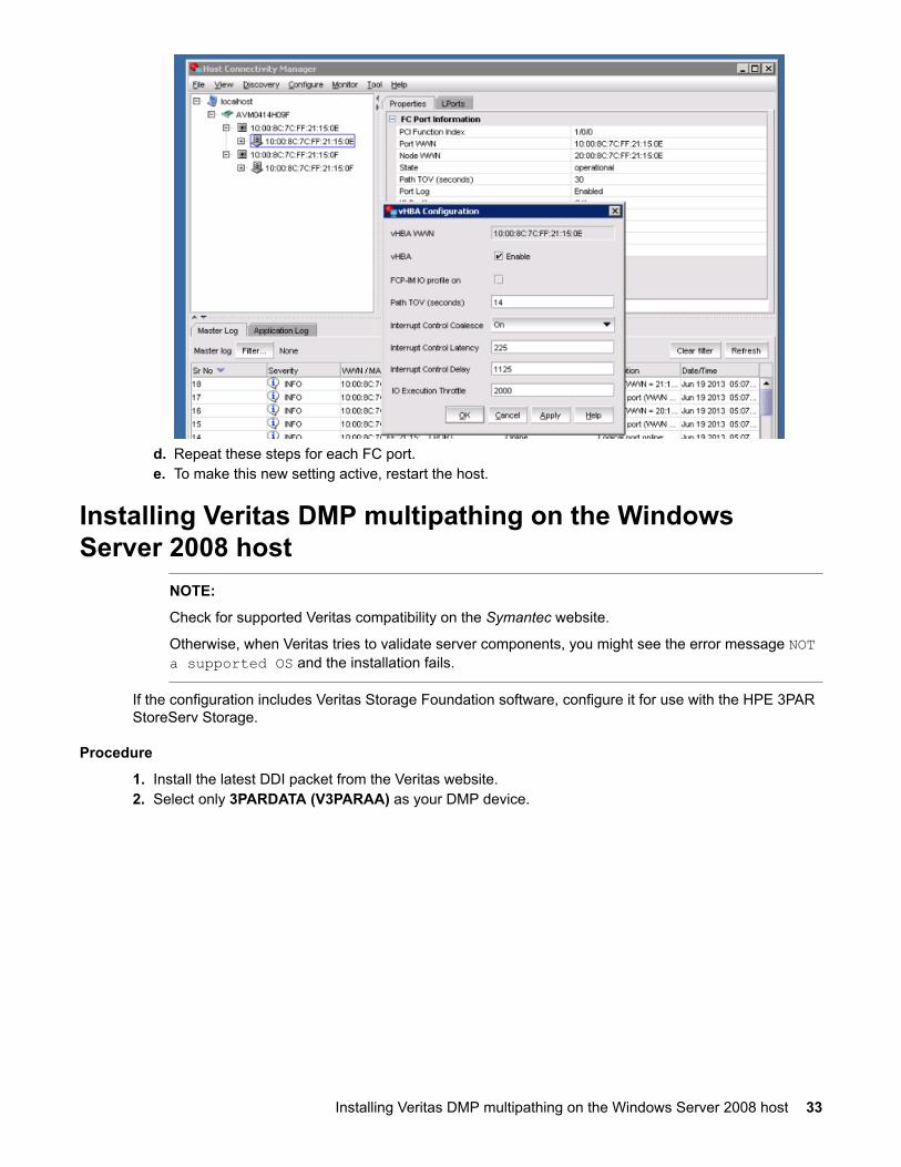
d. Repeat these steps for each FC port.e. To make this new setting active, restart the host.
Installing Veritas DMP multipathing on the WindowsServer 2008 host
NOTE:
Check for supported Veritas compatibility on the Symantec website.
Otherwise, when Veritas tries to validate server components, you might see the error message NOTa supported OS and the installation fails.
If the configuration includes Veritas Storage Foundation software, configure it for use with the HPE 3PARStoreServ Storage.
Procedure
1. Install the latest DDI packet from the Veritas website.2. Select only 3PARDATA (V3PARAA) as your DMP device.
Installing Veritas DMP multipathing on the Windows Server 2008 host 33
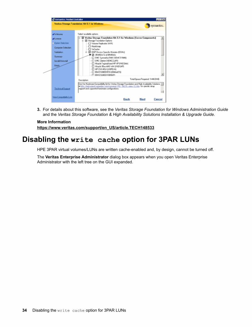
3. For details about this software, see the Veritas Storage Foundation for Windows Administration Guideand the Veritas Storage Foundation & High Availability Solutions Installation & Upgrade Guide.
More Informationhttps://www.veritas.com/support/en_US/article.TECH148533
Disabling the write cache option for 3PAR LUNsHPE 3PAR virtual volumes/LUNs are written cache-enabled and, by design, cannot be turned off.
The Veritas Enterprise Administrator dialog box appears when you open Veritas EnterpriseAdministrator with the left tree on the GUI expanded.
34 Disabling the write cache option for 3PAR LUNs
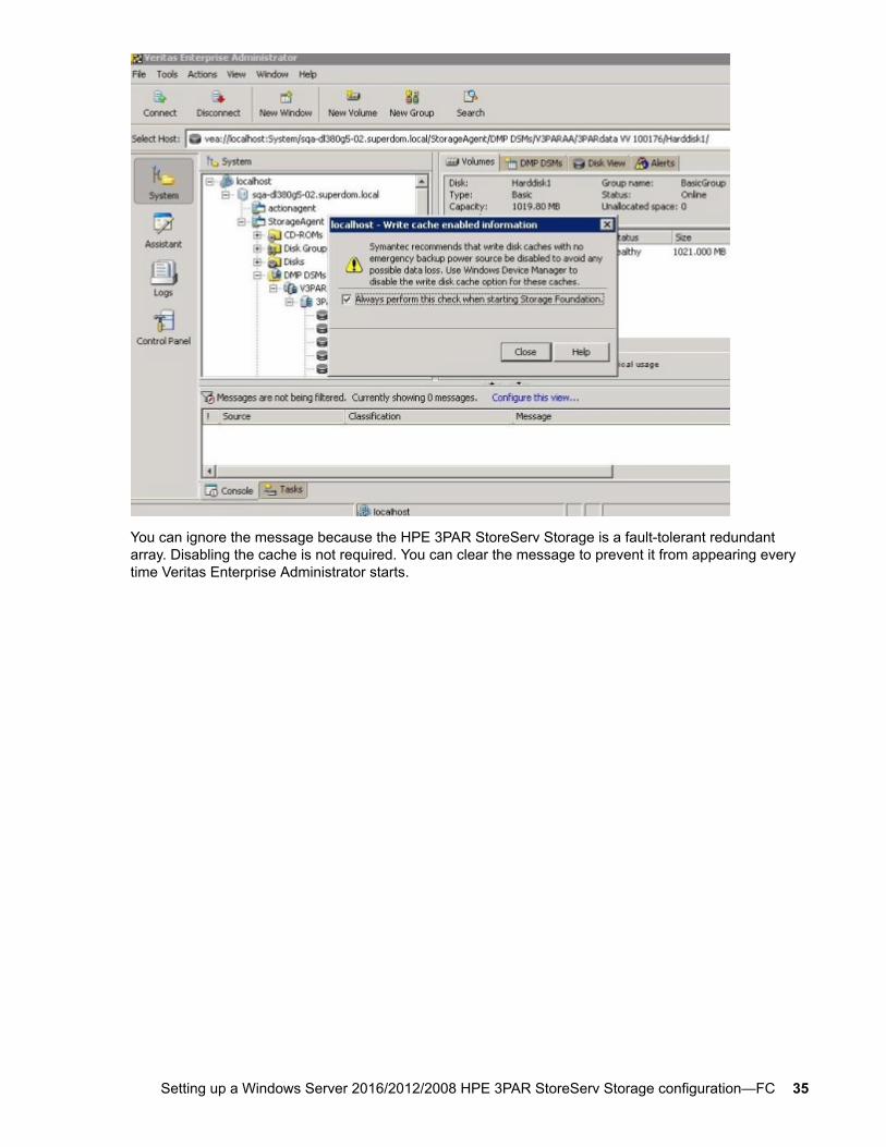
You can ignore the message because the HPE 3PAR StoreServ Storage is a fault-tolerant redundantarray. Disabling the cache is not required. You can clear the message to prevent it from appearing everytime Veritas Enterprise Administrator starts.
Setting up a Windows Server 2016/2012/2008 HPE 3PAR StoreServ Storage configuration—FC 35
Setting up a Windows Server 2016/2012/2008HPE 3PAR StoreServ Storage configuration—iSCSI
The HPE 3PAR StoreServ Storage supports Windows Server 2016, Windows Server 2012, and WindowsServer 2008 software iSCSI initiators.
NOTE:
Hewlett Packard Enterprise recommends using default values to configure your host unlessotherwise specified in the following procedures.
Beginning with HPE 3PAR OS 3.1.2, the HPE 3PAR StoreServ 10000 and 7000 Storage systemssupport hardware iSCSI initiators with supported converged network adapters (CNAs). Hardware iSCSIinitiators are also supported on the HPE 3PAR StoreServ 20000 and 8000 Storage systems. For moreinformation about supported configurations, see the SPOCK website.
To configure supported CNAs, see the specific vendor documentation.
NOTE:
Hewlett Packard Enterprise recommends reading the Microsoft iSCSI Software Initiator Users Guidefor Windows concepts and procedures used in this topic.
More Informationhttp://www.hpe.com/storage/spock
VLAN configuration and routing setupSwitch VLAN configuration and routing setup and configuration are beyond the scope of this document.See your switch manufacturer's guide for instructions about setting up VLANs and routing.
The HPE 3PAR StoreServ Storage arrays support the following VLAN configurations:
• One initiator to one target per VLAN• One initiator to multiple targets per VLAN• Multiple initiators to one target per VLAN• Multiple initiators to multiple targets per VLAN
HPE 3PAR Persistent Ports—iSCSIBeginning with HPE 3PAR OS 3.1.3, the HPE 3PAR Persistent Ports feature is supported for iSCSI.
The HPE 3PAR Persistent Ports (or virtual ports) feature minimizes I/O disruption on an HPE 3PARStoreServ Storage in response to the following events:
• HPE 3PAR OS firmware upgrade• Node maintenance that requires the node to be taken offline (for example, adding a new HBA).• HPE 3PAR node failure• Array target ports being taken offline administratively
Each iSCSI target storage array port has a partner array port automatically assigned by the system.Partner ports are assigned across array node pairs.
36 Setting up a Windows Server 2016/2012/2008 HPE 3PAR StoreServ Storage configuration—iSCSI
HPE 3PAR Persistent Ports allow an HPE 3PAR StoreServ Storage iSCSI port to assume the identity of afailed port while retaining its own identity. Where a given physical port assumes the identity of its partnerport, the assumed port is designated as a persistent port. Array port failover and failback with HPE 3PARPersistent Ports is transparent to most host-based multipathing software, which can keep all its I/O pathsactive.
Beginning with HPE 3PAR OS 3.2.2, the HPE 3PAR Persistent Port feature for iSCSI has additionalfunctionality to minimize I/O disruption during an array port loss_sync event by supporting loss_syncrecovery, automatic failover if there is a failure due to a loss of signal or a link going down between thearray and the switch.
NOTE:
• Use of HPE 3PAR Persistent Ports technology does not negate the need for properly installed,configured, and maintained host multipathing software.
• A key element for iSCSI connectivity is that partner ports must share the same IP network.
For a more complete description of the HPE 3PAR Persistent Ports feature, its operation, and a completelist of required setup and connectivity guidelines, see the following documents:
• Technical white paper HPE 3PAR StoreServ Persistent Ports (Hewlett Packard Enterprise document#F4AA4-4545ENW) at the Hewlett Packard Enterprise Support Center website.
• HPE 3PAR Command Line Interface Administrator’s Manual in the "Using Persistent Ports forNondisruptive Online Software Upgrades" topic at the Hewlett Packard Enterprise Information Librarywebsite.
More Informationhttp://www.hpe.com/support/hpeschttp://www.hpe.com/info/storage/docs
Enterprise iSCSISupport for Enterprise iSCSI or iSCSI over data center bridging (DCB) (lossless Ethernet) began withHPE 3PAR OS 3.2.2. DCB enhances Ethernet LANs for clustering and storage network use. HPE 3PARStoreServ 20000, 9000, and 8000 Storage systems support this feature.
With DCB, you can set up and configure different Ethernet traffic with different priorities, treating them asif they were different pipes. You can allocate bandwidth on links and eliminate packet loss due to queueoverflow.
No special settings are required on the HPE 3PAR iSCSI target port to support Enterprise iSCSI.
Since each SAN environment is different and has different needs, no single switch network configurationapplies to all SAN environments. To configure iSCSI on an Ethernet switch that supports DCB, see theswitch vendor configuration guide.
To configure the HPE 5900 Network switch series, see the HPE FlexFabric 59xx/57xx Switch Series atthe Hewlett Packard Enterprise Information Library.
For information about supported DCB Ethernet switches, see the SPOCK website.
More Informationhttp://www.hpe.com/networking/libraryhttp://www.hpe.com/storage/spock
Enterprise iSCSI 37
Setting up the initiator and target ports—iSCSIIMPORTANT:
With Windows Server 2012/2008 servers connected to HPE 3PAR F200/F400 or T400/T800 1GbiSCSI targets, reducing MPIO failover times requires that MPIO Path Verify is enabled.
Enable Path Verify for Microsoft MPIO:
1. In a command line or PowerShell window, run the regedit command.2. In the registry editor window, navigate to the following registry key:
HKEY_LOCAL_MACHINE\SYSTEM\CurrentControlSet\Services\mpio\Parameters
3. Set the values of UseCustomPathRecoveryInterval to 1 and PathVerifyEnabled to 1.4. Restart the host for these settings to take effect.
You must be able to route the iSCSI traffic between the iSCSI initiator ports and the HPE 3PAR StoreServStorage iSCSI target ports.
Procedure
1. Connect the host iSCSI initiator ports and the HPE 3PAR StoreServ Storage iSCSI target ports to theswitches.
2. To make sure that it sees the HPE 3PAR StoreServ Storage iSCSI target ports, use the pingcommand on the iSCSI initiator host.
Configuring the HPE 3PAR StoreServ Storage—iSCSISupport for IPV6 addressing, as well as IPv4 addressing, for iSCSI ports began with HPE 3PAR OS 3.2.2.3PAR StoreServ 20000, 9000 and 8000 Storage Systems support this feature. The iSCSI target ports onthese arrays support multiple IP addresses for each iSCSI port. The IP addresses can be all IPv6, allIPv4, or a combination of both types of IP addressing.
The HPE 3PAR StoreServ 20000 and 8000 Storage systems also support vLAN tagging for iSCSI withboth IPv4 and IPv6 addressing. To configure the HPE 3PAR StoreServ 20000 or 8000 Storage systemswith IPv6, see HPE 3PAR iSCSI IPv6 addressing and vLAN tagging—iSCSI on page 40.
Procedure
IPv4 addressing for iSCSI:1. If the HPE 3PAR StoreServ Storage iSCSI ports were not configured for iSCSI, use this command:
# controlport config iscsi -f N:S:P
2. Check the current iSCSI port settings: use the showport -iscsi command.
Example showing ports offline and unconfigured:
38 Setting up the initiator and target ports—iSCSI
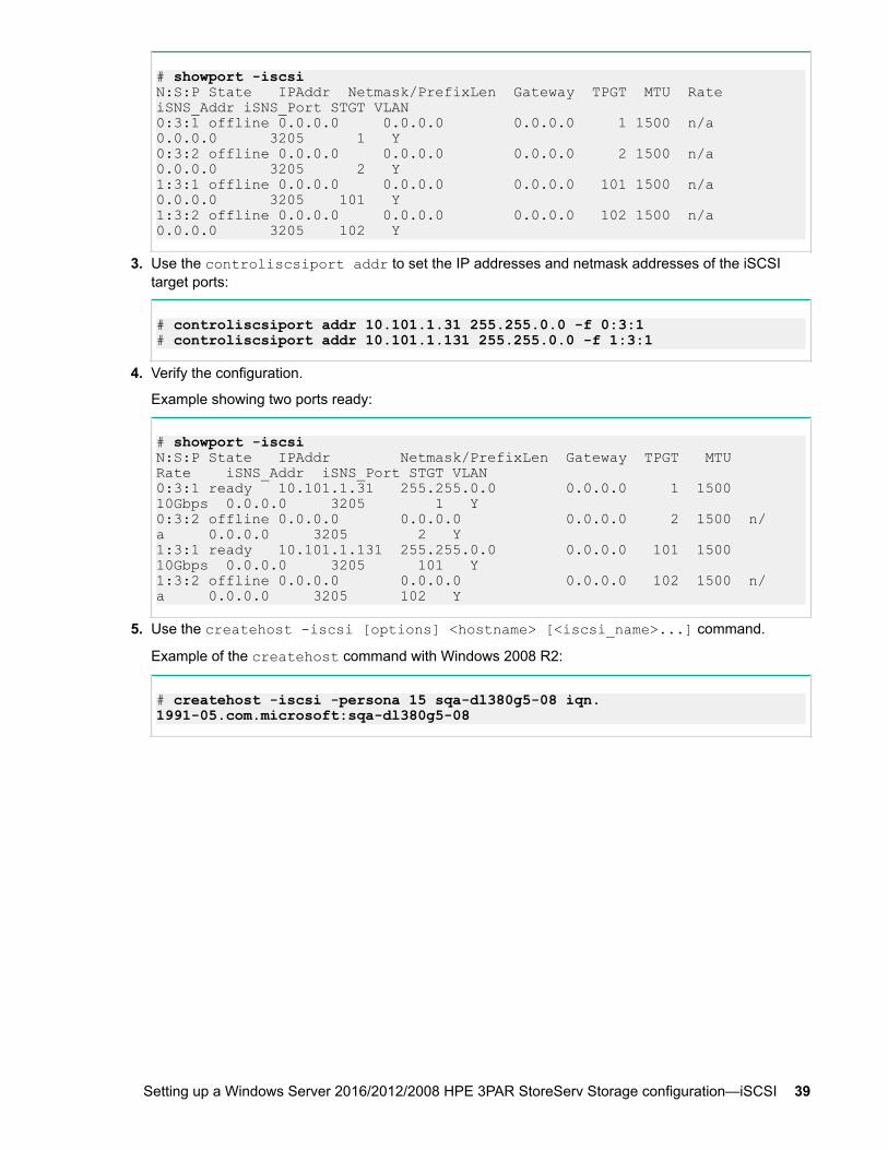
# showport -iscsiN:S:P State IPAddr Netmask/PrefixLen Gateway TPGT MTU Rate iSNS_Addr iSNS_Port STGT VLAN0:3:1 offline 0.0.0.0 0.0.0.0 0.0.0.0 1 1500 n/a 0.0.0.0 3205 1 Y0:3:2 offline 0.0.0.0 0.0.0.0 0.0.0.0 2 1500 n/a 0.0.0.0 3205 2 Y1:3:1 offline 0.0.0.0 0.0.0.0 0.0.0.0 101 1500 n/a 0.0.0.0 3205 101 Y1:3:2 offline 0.0.0.0 0.0.0.0 0.0.0.0 102 1500 n/a 0.0.0.0 3205 102 Y
3. Use the controliscsiport addr to set the IP addresses and netmask addresses of the iSCSItarget ports:
# controliscsiport addr 10.101.1.31 255.255.0.0 -f 0:3:1# controliscsiport addr 10.101.1.131 255.255.0.0 -f 1:3:1
4. Verify the configuration.
Example showing two ports ready:
# showport -iscsiN:S:P State IPAddr Netmask/PrefixLen Gateway TPGT MTU Rate iSNS_Addr iSNS_Port STGT VLAN0:3:1 ready 10.101.1.31 255.255.0.0 0.0.0.0 1 1500 10Gbps 0.0.0.0 3205 1 Y0:3:2 offline 0.0.0.0 0.0.0.0 0.0.0.0 2 1500 n/a 0.0.0.0 3205 2 Y1:3:1 ready 10.101.1.131 255.255.0.0 0.0.0.0 101 1500 10Gbps 0.0.0.0 3205 101 Y1:3:2 offline 0.0.0.0 0.0.0.0 0.0.0.0 102 1500 n/a 0.0.0.0 3205 102 Y
5. Use the createhost -iscsi [options] <hostname> [<iscsi_name>...] command.
Example of the createhost command with Windows 2008 R2:
# createhost -iscsi -persona 15 sqa-dl380g5-08 iqn.1991-05.com.microsoft:sqa-dl380g5-08
Setting up a Windows Server 2016/2012/2008 HPE 3PAR StoreServ Storage configuration—iSCSI 39
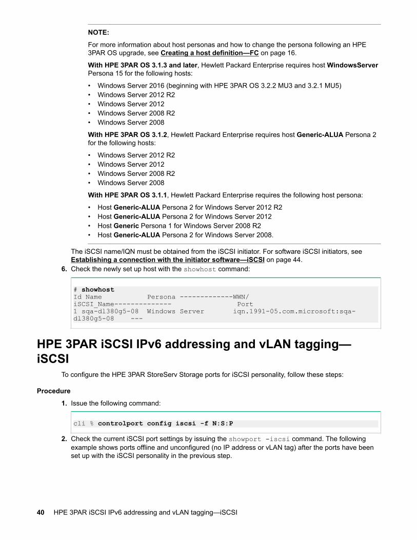
NOTE:
For more information about host personas and how to change the persona following an HPE3PAR OS upgrade, see Creating a host definition—FC on page 16.
With HPE 3PAR OS 3.1.3 and later, Hewlett Packard Enterprise requires host WindowsServerPersona 15 for the following hosts:
• Windows Server 2016 (beginning with HPE 3PAR OS 3.2.2 MU3 and 3.2.1 MU5)• Windows Server 2012 R2• Windows Server 2012• Windows Server 2008 R2• Windows Server 2008
With HPE 3PAR OS 3.1.2, Hewlett Packard Enterprise requires host Generic-ALUA Persona 2for the following hosts:
• Windows Server 2012 R2• Windows Server 2012• Windows Server 2008 R2• Windows Server 2008
With HPE 3PAR OS 3.1.1, Hewlett Packard Enterprise requires the following host persona:
• Host Generic-ALUA Persona 2 for Windows Server 2012 R2• Host Generic-ALUA Persona 2 for Windows Server 2012• Host Generic Persona 1 for Windows Server 2008 R2• Host Generic-ALUA Persona 2 for Windows Server 2008.
The iSCSI name/IQN must be obtained from the iSCSI initiator. For software iSCSI initiators, see Establishing a connection with the initiator software—iSCSI on page 44.
6. Check the newly set up host with the showhost command:
# showhostId Name Persona -------------WWN/iSCSI_Name-------------- Port1 sqa-dl380g5-08 Windows Server iqn.1991-05.com.microsoft:sqa-dl380g5-08 ---
HPE 3PAR iSCSI IPv6 addressing and vLAN tagging—iSCSI
To configure the HPE 3PAR StoreServ Storage ports for iSCSI personality, follow these steps:
Procedure
1. Issue the following command:
cli % controlport config iscsi -f N:S:P
2. Check the current iSCSI port settings by issuing the showport -iscsi command. The followingexample shows ports offline and unconfigured (no IP address or vLAN tag) after the ports have beenset up with the iSCSI personality in the previous step.
40 HPE 3PAR iSCSI IPv6 addressing and vLAN tagging—iSCSI
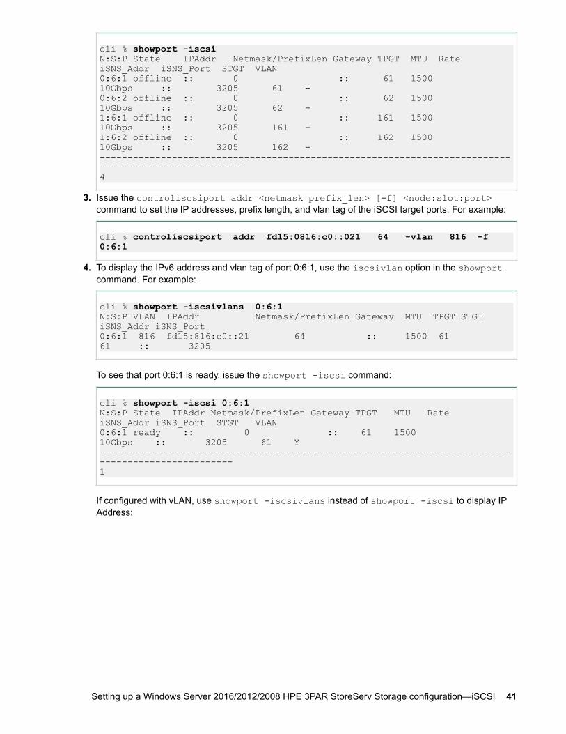
cli % showport -iscsiN:S:P State IPAddr Netmask/PrefixLen Gateway TPGT MTU Rate iSNS_Addr iSNS_Port STGT VLAN0:6:1 offline :: 0 :: 61 1500 10Gbps :: 3205 61 - 0:6:2 offline :: 0 :: 62 1500 10Gbps :: 3205 62 - 1:6:1 offline :: 0 :: 161 1500 10Gbps :: 3205 161 - 1:6:2 offline :: 0 :: 162 1500 10Gbps :: 3205 162 - ----------------------------------------------------------------------------------------------------4
3. Issue the controliscsiport addr <netmask|prefix_len> [-f] <node:slot:port>command to set the IP addresses, prefix length, and vlan tag of the iSCSI target ports. For example:
cli % controliscsiport addr fd15:0816:c0::021 64 -vlan 816 -f 0:6:1
4. To display the IPv6 address and vlan tag of port 0:6:1, use the iscsivlan option in the showportcommand. For example:
cli % showport -iscsivlans 0:6:1N:S:P VLAN IPAddr Netmask/PrefixLen Gateway MTU TPGT STGT iSNS_Addr iSNS_Port0:6:1 816 fd15:816:c0::21 64 :: 1500 61 61 :: 3205
To see that port 0:6:1 is ready, issue the showport -iscsi command:
cli % showport -iscsi 0:6:1N:S:P State IPAddr Netmask/PrefixLen Gateway TPGT MTU Rate iSNS_Addr iSNS_Port STGT VLAN0:6:1 ready :: 0 :: 61 1500 10Gbps :: 3205 61 Y--------------------------------------------------------------------------------------------------1
If configured with vLAN, use showport -iscsivlans instead of showport -iscsi to display IPAddress:
Setting up a Windows Server 2016/2012/2008 HPE 3PAR StoreServ Storage configuration—iSCSI 41

cli % showport -iscsivlansN:S:P VLAN IPAddr Netmask/PrefixLen Gateway MTU TPGT STGT iSNS_Addr iSNS_Port0:6:1 - 10.101.1.61 255.255.255.0 10.101.1.1 1500 61 61 0.0.0.0 32050:6:2 - :: 0 :: 1500 62 62 :: 32050:6:2 62 fd15:816:c0:21 64 :: 1500 62 62 :: 32051:6:1 - 10.101.2.161 255.255.255.0 10.101.2.1 1500 161 161 0.0.0.0 32051:6:2 - :: 0 :: 1500 162 162 :: 32051:6:2 162 fd15:1816:c0:21 64 :: 1500 162 162 :: 3205----------------------------------------------------------------------------------------------6
NOTE:
To configure IPv4 addressing and vLAN tagging on the HPE 3PAR StoreServ Storage systems,follow the steps in Configuring the HPE 3PAR StoreServ Storage—iSCSI on page 38, whichdescribe how to configure IPv4 for the HPE 3PAR StoreServ Storage systems, with oneexception: When configuring an IPv4 address with the vLAN number that you want to assign tothe IPv4 address, the -vlan option must be used.
Configuring host no traffic reattach—iSCSIFollow these steps to reattach any dropped multipath connections that are currently not carrying traffic.
Procedure
1. Change the EnableNOPOut parameter for the iSCSI initiator in the Windows registry (iSCSI Ping):
[HKEY_LOCAL_MACHINE\SYSTEM\CurrentControlSet\Control\Class\{4D36E97B-E325-11CE-BFC1-08002BE10318}\0005\Parameters]
NOTE:
The \0005\ part of the registry path may be a different decimal number, such as \0003\,depending on your system setup.
2. Change the EnableNOPOut value from 00000000 to 00000001:
"EnableNOPOut"=dword:00000001
3. Restart the servers for the change to take effect.
Using the Microsoft iSNS server to discover registrationsThe Microsoft iSNS server is used to discover the iSCSI initiator and iSCSI targets on the dedicatednetwork. When the iSCSI initiator and iSCSI targets are registered with the iSNS server, they
42 Configuring host no traffic reattach—iSCSI
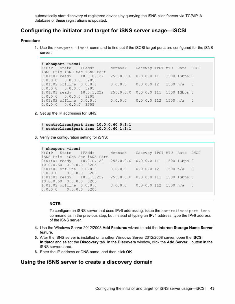
automatically start discovery of registered devices by querying the iSNS client/server via TCP/IP. Adatabase of these registrations is updated.
Configuring the initiator and target for iSNS server usage—iSCSI
Procedure
1. Use the showport -iscsi command to find out if the iSCSI target ports are configured for the iSNSserver:
# showport -iscsiN:S:P State IPAddr Netmask Gateway TPGT MTU Rate DHCP iSNS Prim iSNS Sec iSNS Port0:01:01 ready 10.0.0.122 255.0.0.0 0.0.0.0 11 1500 1Gbps 0 0.0.0.0 0.0.0.0 32050:01:02 offline 0.0.0.0 0.0.0.0 0.0.0.0 12 1500 n/a 0 0.0.0.0 0.0.0.0 32051:01:01 ready 10.0.1.222 255.0.0.0 0.0.0.0 111 1500 1Gbps 0 0.0.0.0 0.0.0.0 32051:01:02 offline 0.0.0.0 0.0.0.0 0.0.0.0 112 1500 n/a 0 0.0.0.0 0.0.0.0 3205
2. Set up the IP addresses for iSNS:
# controliscsiport isns 10.0.0.60 0:1:1# controliscsiport isns 10.0.0.60 1:1:1
3. Verify the configuration setting for iSNS:
# showport -iscsiN:S:P State IPAddr Netmask Gateway TPGT MTU Rate DHCP iSNS Prim iSNS Sec iSNS Port0:01:01 ready 10.0.0.122 255.0.0.0 0.0.0.0 11 1500 1Gbps 0 10.0.0.60 0.0.0.0 32050:01:02 offline 0.0.0.0 0.0.0.0 0.0.0.0 12 1500 n/a 0 0.0.0.0 0.0.0.0 32051:01:01 ready 10.0.1.222 255.0.0.0 0.0.0.0 111 1500 1Gbps 0 10.0.0.60 0.0.0.0 32051:01:02 offline 0.0.0.0 0.0.0.0 0.0.0.0 112 1500 n/a 0 0.0.0.0 0.0.0.0 3205
NOTE:
To configure an iSNS server that uses IPv6 addressing, issue the controliscsiport isnscommand as in the previous step, but instead of typing an IPv4 address, type the IPv6 addressof the iSNS server.
4. Use the Windows Server 2012/2008 Add Features wizard to add the Internet Storage Name Serverfeature.
5. After the iSNS server is installed on another Windows Server 2012/2008 server, open the iSCSIInitiator and select the Discovery tab. In the Discovery window, click the Add Server... button in theiSNS servers area.
6. Enter the IP address or DNS name, and then click OK.
Using the iSNS server to create a discovery domain
Configuring the initiator and target for iSNS server usage—iSCSI 43
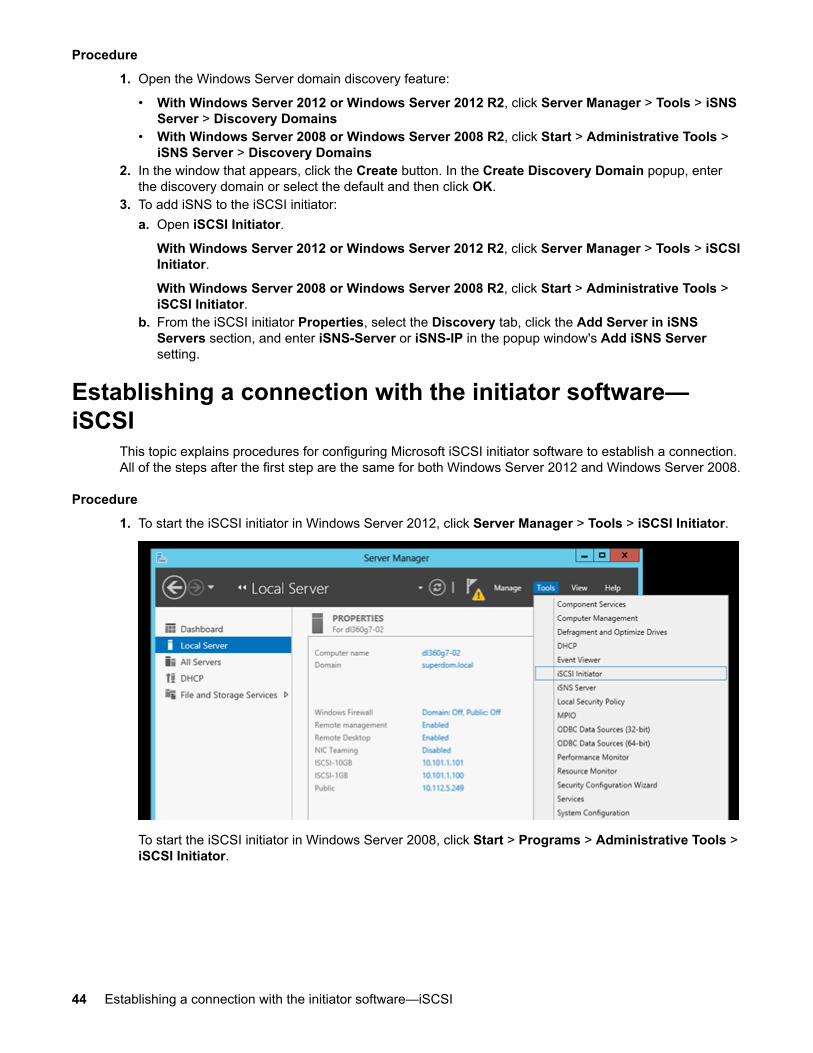
Procedure
1. Open the Windows Server domain discovery feature:
• With Windows Server 2012 or Windows Server 2012 R2, click Server Manager > Tools > iSNSServer > Discovery Domains
• With Windows Server 2008 or Windows Server 2008 R2, click Start > Administrative Tools >iSNS Server > Discovery Domains
2. In the window that appears, click the Create button. In the Create Discovery Domain popup, enterthe discovery domain or select the default and then click OK.
3. To add iSNS to the iSCSI initiator:a. Open iSCSI Initiator.
With Windows Server 2012 or Windows Server 2012 R2, click Server Manager > Tools > iSCSIInitiator.
With Windows Server 2008 or Windows Server 2008 R2, click Start > Administrative Tools >iSCSI Initiator.
b. From the iSCSI initiator Properties, select the Discovery tab, click the Add Server in iSNSServers section, and enter iSNS-Server or iSNS-IP in the popup window's Add iSNS Serversetting.
Establishing a connection with the initiator software—iSCSI
This topic explains procedures for configuring Microsoft iSCSI initiator software to establish a connection.All of the steps after the first step are the same for both Windows Server 2012 and Windows Server 2008.
Procedure
1. To start the iSCSI initiator in Windows Server 2012, click Server Manager > Tools > iSCSI Initiator.
To start the iSCSI initiator in Windows Server 2008, click Start > Programs > Administrative Tools >iSCSI Initiator.
44 Establishing a connection with the initiator software—iSCSI
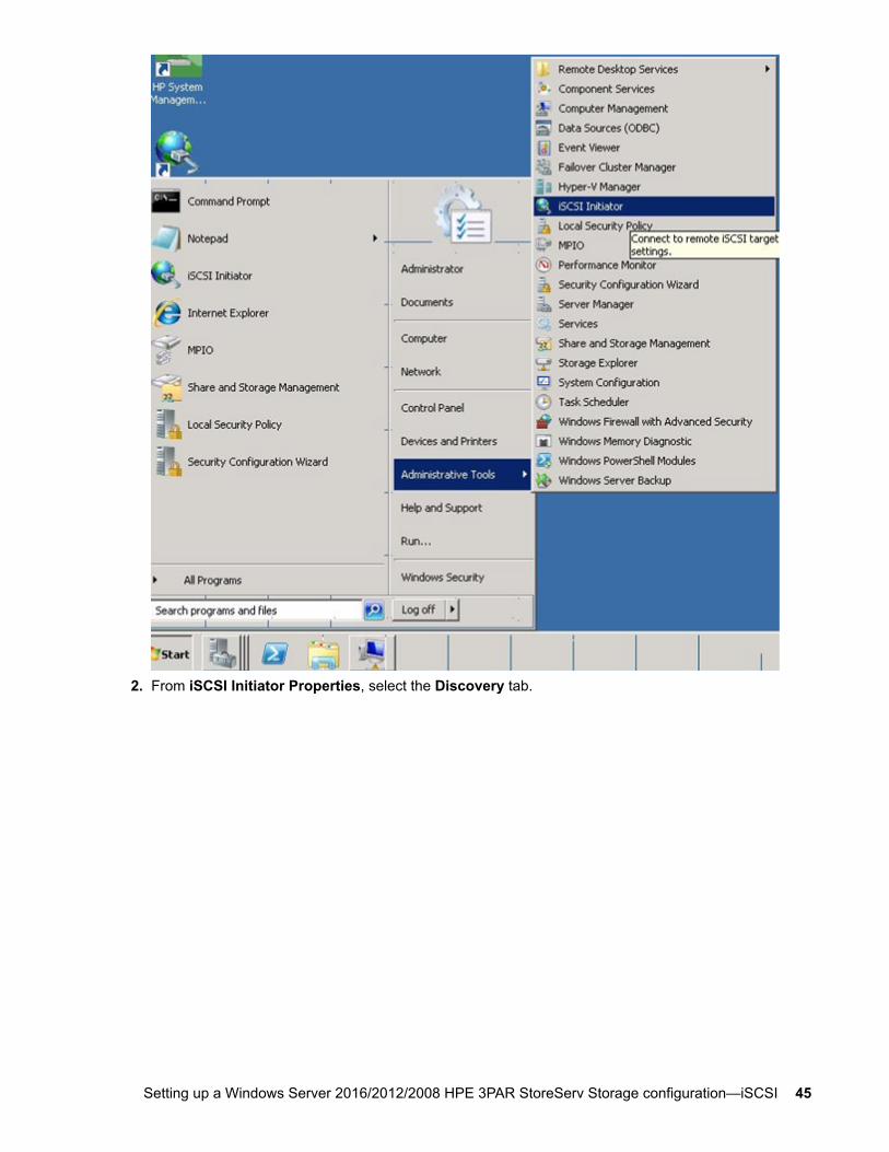
2. From iSCSI Initiator Properties, select the Discovery tab.
Setting up a Windows Server 2016/2012/2008 HPE 3PAR StoreServ Storage configuration—iSCSI 45

3. On the Discovery tab Target portals area, click the Discover Portal... button, and in the DiscoverTarget Portal dialog box, enter the IP address of the portal you want to add.
46 Setting up a Windows Server 2016/2012/2008 HPE 3PAR StoreServ Storage configuration—iSCSI

4. To establish the connection, click Advanced. The Advanced Settings dialog box appears.
In the Connect using section of this dialog box:
Setting up a Windows Server 2016/2012/2008 HPE 3PAR StoreServ Storage configuration—iSCSI 47
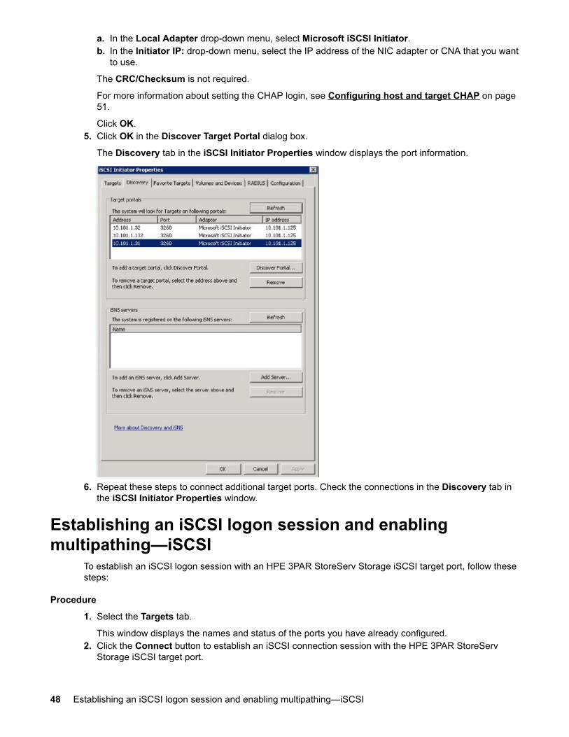
a. In the Local Adapter drop-down menu, select Microsoft iSCSI Initiator.b. In the Initiator IP: drop-down menu, select the IP address of the NIC adapter or CNA that you want
to use.
The CRC/Checksum is not required.
For more information about setting the CHAP login, see Configuring host and target CHAP on page51.
Click OK.5. Click OK in the Discover Target Portal dialog box.
The Discovery tab in the iSCSI Initiator Properties window displays the port information.
6. Repeat these steps to connect additional target ports. Check the connections in the Discovery tab inthe iSCSI Initiator Properties window.
Establishing an iSCSI logon session and enablingmultipathing—iSCSI
To establish an iSCSI logon session with an HPE 3PAR StoreServ Storage iSCSI target port, follow thesesteps:
Procedure
1. Select the Targets tab.
This window displays the names and status of the ports you have already configured.2. Click the Connect button to establish an iSCSI connection session with the HPE 3PAR StoreServ
Storage iSCSI target port.
48 Establishing an iSCSI logon session and enabling multipathing—iSCSI
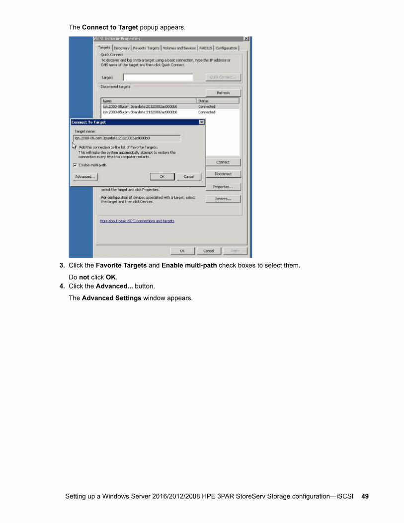
The Connect to Target popup appears.
3. Click the Favorite Targets and Enable multi-path check boxes to select them.
Do not click OK.4. Click the Advanced... button.
The Advanced Settings window appears.
Setting up a Windows Server 2016/2012/2008 HPE 3PAR StoreServ Storage configuration—iSCSI 49

5. In the Connect using section, choose the following options:
NOTE:
The Microsoft iSCSI initiator will not work correctly if you have multiple local adapters, source IPaddresses, and target ports and keep the default settings.
• Choose Microsoft iSCSI Initiator from the Local adapter drop-down menu.• Choose the IP address of the NIC adapter or CNA in your system that will connect to the iSCSI
target port from the Initiator IP drop-down menu.• Choose the IP address of the target portal (iSCSI target port) from the Target Portal IP drop-down
menu.6. In the Advanced Settings window, click OK, and then click OK in the Connect to Target window.
The iSCSI initiator will establish an iSCSI session with the target port.7. If desired, verify the connection:
In the Targets section of the iSCSI Initiator Properties window, the Status column for the target willshow the status as Connected.
8. Perform steps 4 through 7 to add the connection to the second target portal. The iSCSI InitiatorProperties window shows the status of both.
50 Setting up a Windows Server 2016/2012/2008 HPE 3PAR StoreServ Storage configuration—iSCSI
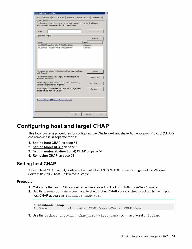
Configuring host and target CHAPThis topic contains procedures for configuring the Challenge-Handshake Authentication Protocol (CHAP)and removing it, in separate topics:
1. Setting host CHAP on page 512. Setting target CHAP on page 523. Setting mutual (bidirectional) CHAP on page 544. Removing CHAP on page 54
Setting host CHAPTo set a host CHAP secret, configure it on both the HPE 3PAR StoreServ Storage and the WindowsServer 2012/2008 host. Follow these steps:
Procedure
1. Make sure that an iSCSI host definition was created on the HPE 3PAR StoreServ Storage.2. Use the showhost -chap command to show that no CHAP secret is already set up. In the output,
host CHAP appears as Initiator_CHAP_Name:
# showhost -chapId Name -Initiator_CHAP_Name- -Target_CHAP_Name
3. Use the sethost initchap <chap_name> <host_name> command to set initchap:
Configuring host and target CHAP 51
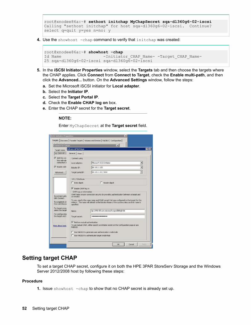
root@xnodee86a:~# sethost initchap MyChapSecret sqa-dl360g6-02-iscsiCalling "sethost initchap" for host sqa-dl360g6-02-iscsi. Continue?select q=quit y=yes n=no: y
4. Use the showhost -chap command to verify that initchap was created:
root@xnodee86a:~# showhost -chapId Name -Initiator_CHAP_Name- -Target_CHAP_Name-25 sqa-dl360g6-02-iscsi sqa-dl360g6-02-iscsi
5. In the iSCSI Initiator Properties window, select the Targets tab and then choose the targets wherethe CHAP applies. Click Connect from Connect to Target, check the Enable multi-path, and thenclick the Advanced... button. On the Advanced Settings window, follow the steps:a. Set the Microsoft iSCSI initiator for Local adapter.b. Select the Initiator IP.c. Select the Target Portal IP.d. Check the Enable CHAP log on box.e. Enter the CHAP secret for the Target secret.
NOTE:
Enter MyChapSecret at the Target secret field.
Setting target CHAPTo set a target CHAP secret, configure it on both the HPE 3PAR StoreServ Storage and the WindowsServer 2012/2008 host by following these steps:
Procedure
1. Issue showhost -chap to show that no CHAP secret is already set up.
52 Setting target CHAP
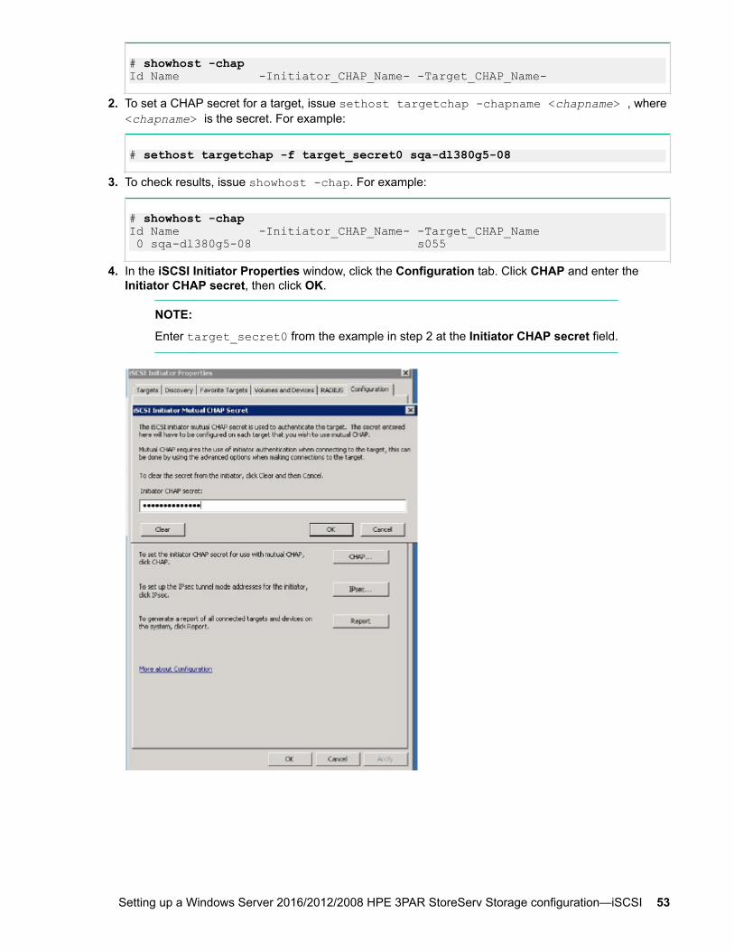
# showhost -chapId Name -Initiator_CHAP_Name- -Target_CHAP_Name-
2. To set a CHAP secret for a target, issue sethost targetchap -chapname <chapname> , where<chapname> is the secret. For example:
# sethost targetchap -f target_secret0 sqa-dl380g5-08
3. To check results, issue showhost -chap. For example:
# showhost -chapId Name -Initiator_CHAP_Name- -Target_CHAP_Name 0 sqa-dl380g5-08 s055
4. In the iSCSI Initiator Properties window, click the Configuration tab. Click CHAP and enter theInitiator CHAP secret, then click OK.
NOTE:
Enter target_secret0 from the example in step 2 at the Initiator CHAP secret field.
Setting up a Windows Server 2016/2012/2008 HPE 3PAR StoreServ Storage configuration—iSCSI 53
Setting mutual (bidirectional) CHAP
Procedure
1. Set the host CHAP secret following instructions in Setting host CHAP on page 51.2. Set the target CHAP secret following instructions in Setting target CHAP on page 52.3. Issue showhost -chap. The output shows both secrets set:
# showhost -chapId Name -Initiator_CHAP_Name- -Target_CHAP_Name 0 sqa-dl380g5-08 sqa-dl380g5-08 s055
Removing CHAPFollow these steps to remove the Challenge-Handshake Authentication Protocol (CHAP) from the HPE3PAR StoreServ Storage hosts.
Procedure
1. Issue sethost removechap; this command removes all CHAP information for all specified hosts.For example:
# sethost removechap sqa-dl380g5-0Calling "sethost removechap" for host sqa-dl380g5-08. Continue?select q=quit y=yes n=no: y
2. To check status, issue showhost -chap. For example:
# showhost -chapId Name -Initiator_CHAP_Name- -Target_CHAP_Name- 0 sqa-dl380g5-08 --
3. In the iSCSI Initiator Properties window, click the Targets tab where the CHAP applies; click theConnect button from the Connect to Target window and check the Enable multi-path option. Thenclick the Advanced... button and in the Advanced Settings window, follow these steps:a. In the Local adapter field, select Microsoft iSCSI initiator.b. Select the Initiator IP.c. Select the Target portal IP.d. Clear the Enable CHAP log on check box.
54 Setting mutual (bidirectional) CHAP
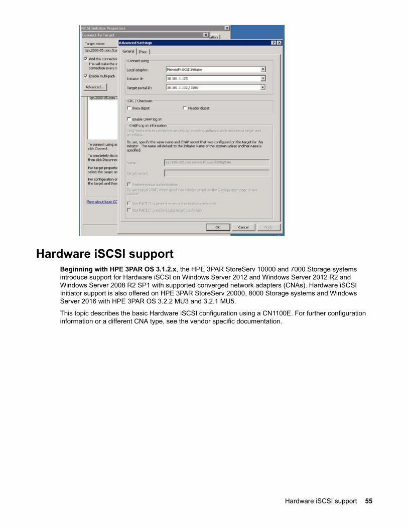
Hardware iSCSI supportBeginning with HPE 3PAR OS 3.1.2.x, the HPE 3PAR StoreServ 10000 and 7000 Storage systemsintroduce support for Hardware iSCSI on Windows Server 2012 and Windows Server 2012 R2 andWindows Server 2008 R2 SP1 with supported converged network adapters (CNAs). Hardware iSCSIInitiator support is also offered on HPE 3PAR StoreServ 20000, 8000 Storage systems and WindowsServer 2016 with HPE 3PAR OS 3.2.2 MU3 and 3.2.1 MU5.
This topic describes the basic Hardware iSCSI configuration using a CN1100E. For further configurationinformation or a different CNA type, see the vendor specific documentation.
Hardware iSCSI support 55

NOTE:
• For Hardware iSCSI with QLogic CNAs, the ARP Redirect feature must be enabled in the hostcard firmware to support path failover with HPE 3PAR Persistent Ports. This includes using theHardware iSCSI initiator of the CN1000Q CNA.
This can be done through the QLogic Converge Console Utility. In the firmware settings of eachiSCSI port, selected the IPv4 Network Settings, and then ensure ARP Redirect is checked.
• For the Hardware iSCSI with Emulex CNAs, the UCNA driver has an extended timeout value setto 90 seconds. This setting determines the amount of time the UCNA driver will wait for thetarget to become available after it has lost connection to the target during an I/O operation.
If the iSCSI initiator loses a path to the target, this default value delays any MPIO operations untilthe timeout is reached, causing a significant delay in I/O operations.
The following registry entry can be modified to reduce the delay in I/O operations. For example,reducing this value to 30 seconds can result in the delay in I/O operations being reduced to lessthan 40 seconds.
This setting is required prior to connecting to iSCSI target.
Updating the timeout value:
1. In a command shell or PowerShell window, run the regedit command2. In the registry editor window, navigate to the following registry key:
HKEY_LOCAL_MACHINE\System\CurrentControlSet\Services\be2iscsi\Parameters\Device
3. Change the DriversParamaters string value, modifying it to eto=30 or adding eto=30 asrequired.
4. Restart the host for the setting to take effect.
Verify that the ETO setting is 30 in OneCommand Manager in the Target Portal Information for bothadapter ports. If not, set the ETO setting to 30 in OneCommand Manager.
The CNA can be configured by using either Dependent iSCSI (the IP address of the system is obtainedfrom the host NIC connections) or Independent iSCSI (the IP address is entered into the CNA card). TheCN1100E can be configured to boot from SAN. SCSI targets are entered into the card. For generalinformation about the CN1100E, see the Hewlett Packard Enterprise Support Center.
For more information about supported models and configurations, see the SPOCK website.
Requirements for the Software iSCSI listed above (regarding port setup, network connectivity, and VLANconfiguration) also apply for Hardware iSCSI.
56 Setting up a Windows Server 2016/2012/2008 HPE 3PAR StoreServ Storage configuration—iSCSI

More Informationhttp://www.hpe.com/support/hpeschttp://www.hpe.com/storage/spock
Setting the static IP address
Procedure
1. After installing the CN1100E, boot the system. The following text appears in the BIOS:
Emulex 10Gb iSCSI Initiator BIOS..Press <Ctrl> <S> for iSCSISelect (M) Utility
2. Press Ctrl+S to enter the utility.
3. Select a controller and press Enter.4. From the Controller Configuration screen, select Network Configuration and press Enter.5. In the Network Configuration screen, select Configure Static IP Address and press Enter. The
screen for setting a static IP address appears.
6. After entering the IP address, subnet mask, and default gateway, click Save to return to the ControllerConfiguration menu.
Setting the static IP address 57
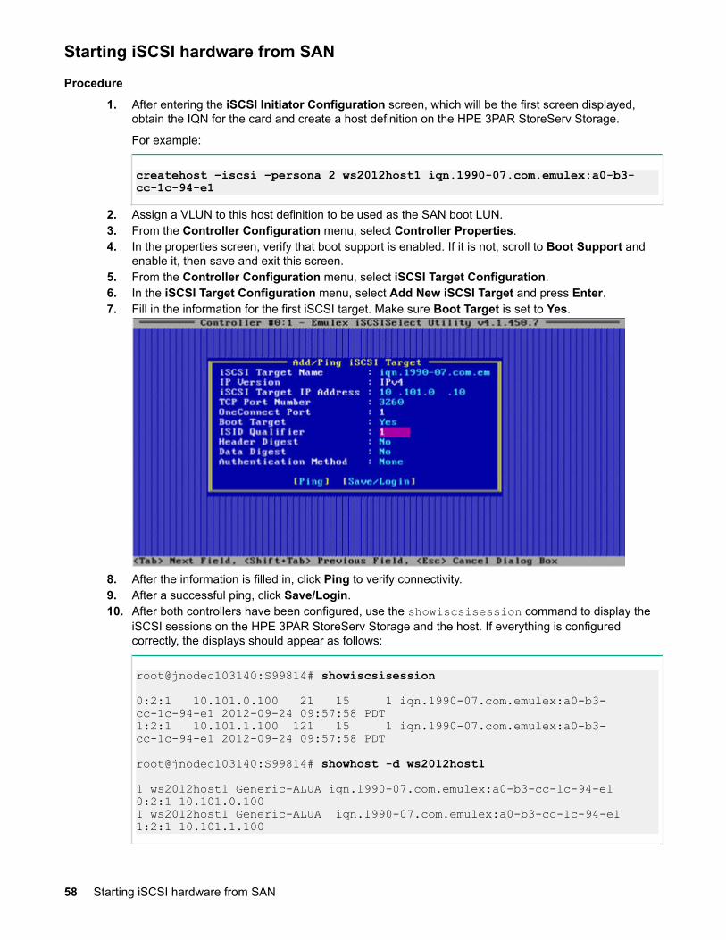
Starting iSCSI hardware from SAN
Procedure
1. After entering the iSCSI Initiator Configuration screen, which will be the first screen displayed,obtain the IQN for the card and create a host definition on the HPE 3PAR StoreServ Storage.
For example:
createhost –iscsi –persona 2 ws2012host1 iqn.1990-07.com.emulex:a0-b3-cc-1c-94-e1
2. Assign a VLUN to this host definition to be used as the SAN boot LUN.3. From the Controller Configuration menu, select Controller Properties.4. In the properties screen, verify that boot support is enabled. If it is not, scroll to Boot Support and
enable it, then save and exit this screen.5. From the Controller Configuration menu, select iSCSI Target Configuration.6. In the iSCSI Target Configuration menu, select Add New iSCSI Target and press Enter.7. Fill in the information for the first iSCSI target. Make sure Boot Target is set to Yes.
8. After the information is filled in, click Ping to verify connectivity.9. After a successful ping, click Save/Login.10. After both controllers have been configured, use the showiscsisession command to display the
iSCSI sessions on the HPE 3PAR StoreServ Storage and the host. If everything is configuredcorrectly, the displays should appear as follows:
root@jnodec103140:S99814# showiscsisession
0:2:1 10.101.0.100 21 15 1 iqn.1990-07.com.emulex:a0-b3-cc-1c-94-e1 2012-09-24 09:57:58 PDT1:2:1 10.101.1.100 121 15 1 iqn.1990-07.com.emulex:a0-b3-cc-1c-94-e1 2012-09-24 09:57:58 PDT
root@jnodec103140:S99814# showhost -d ws2012host1
1 ws2012host1 Generic-ALUA iqn.1990-07.com.emulex:a0-b3-cc-1c-94-e1 0:2:1 10.101.0.1001 ws2012host1 Generic-ALUA iqn.1990-07.com.emulex:a0-b3-cc-1c-94-e1 1:2:1 10.101.1.100
58 Starting iSCSI hardware from SAN

11. To not use CHAP as an authentication method, exit the CN1100E setup screens, and then restartnow.
To use CHAP as an authentication method, return to the Add/Ping iSCSI Target screen, selectAuthentication Method, and then choose one of the following options:
• Select One-Way CHAP.
The CHAP Configuration screen appears.
Type the Target CHAP Name (the initiator IQN name) and Target Secret. Click OK.• In the Authentication Method setting on the Add-Ping iSCSI Target screen, select Mutual
CHAP. The CHAP Configuration screen appears.
Setting up a Windows Server 2016/2012/2008 HPE 3PAR StoreServ Storage configuration—iSCSI 59
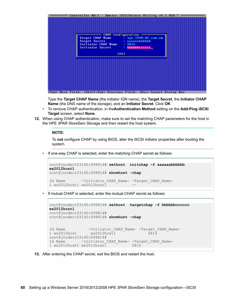
Type the Target CHAP Name (the initiator IQN name), the Target Secret, the Initiator CHAPName (the DNS name of the storage), and an Initiator Secret. Click OK
• To remove CHAP authentication, in theAuthentication Method setting on the Add-Ping iSCSITarget screen, select None.
12. When using CHAP authentication, make sure to set the matching CHAP parameters for the host inthe HPE 3PAR StoreServ Storage and then restart the host system.
NOTE:
To not configure CHAP by using BIOS, alter the iSCSI initiator properties after booting thesystem.
• If one-way CHAP is selected, enter the matching CHAP secret as follows:
root@jnodec103140:S99814# sethost initchap -f aaaaaabbbbbb ws2012host1root@jnodec103140:S99814# showhost -chap
Id Name -Initiator_CHAP_Name- -Target_CHAP_Name-1 ws2012host1 ws2012host1 --
• If mutual CHAP is selected, enter the mutual CHAP secret as follows:
root@jnodec103140:S99814# sethost targetchap -f bbbbbbcccccc ws2012host1root@jnodec103140:S99814#root@jnodec103140:S99814# showhost -chap
Id Name -Initiator_CHAP_Name- -Target_CHAP_Name-1 ws2012host ws2012host1 S814root@jnodec103140:S99814#Id Name -Initiator_CHAP_Name- -Target_CHAP_Name-1 ws2012host1 ws2012host1 S814
13. After entering the CHAP secret, exit the BIOS and restart the host.
60 Setting up a Windows Server 2016/2012/2008 HPE 3PAR StoreServ Storage configuration—iSCSI
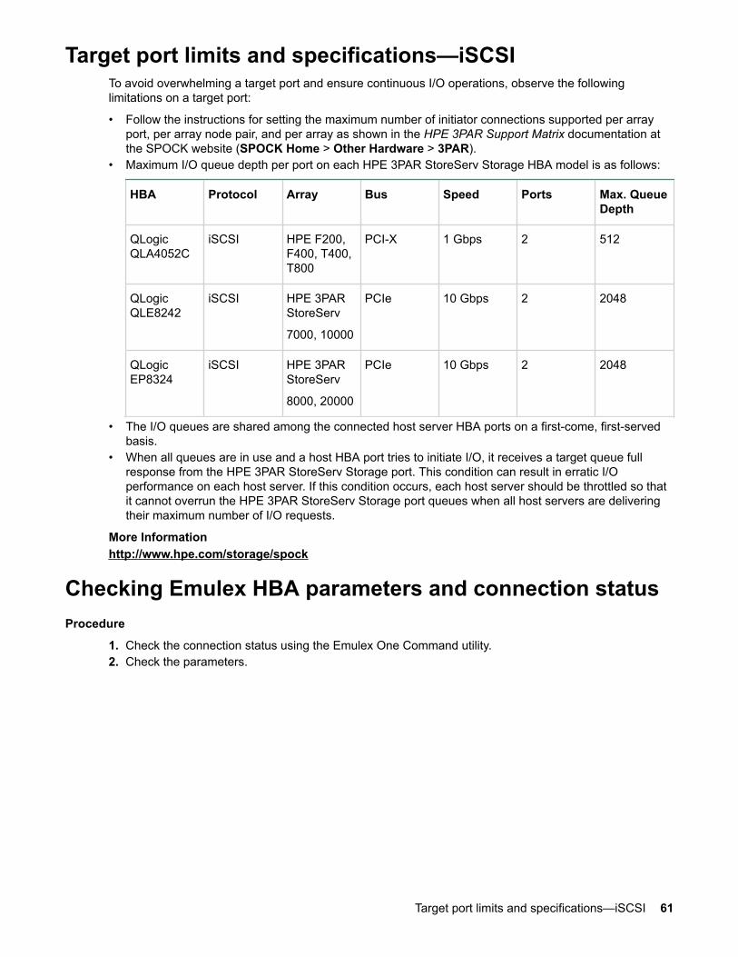
Target port limits and specifications—iSCSITo avoid overwhelming a target port and ensure continuous I/O operations, observe the followinglimitations on a target port:
• Follow the instructions for setting the maximum number of initiator connections supported per arrayport, per array node pair, and per array as shown in the HPE 3PAR Support Matrix documentation atthe SPOCK website (SPOCK Home > Other Hardware > 3PAR).
• Maximum I/O queue depth per port on each HPE 3PAR StoreServ Storage HBA model is as follows:
HBA Protocol Array Bus Speed Ports Max. QueueDepth
QLogicQLA4052C
iSCSI HPE F200,F400, T400,T800
PCI-X 1 Gbps 2 512
QLogicQLE8242
iSCSI HPE 3PARStoreServ
7000, 10000
PCIe 10 Gbps 2 2048
QLogicEP8324
iSCSI HPE 3PARStoreServ
8000, 20000
PCIe 10 Gbps 2 2048
• The I/O queues are shared among the connected host server HBA ports on a first-come, first-servedbasis.
• When all queues are in use and a host HBA port tries to initiate I/O, it receives a target queue fullresponse from the HPE 3PAR StoreServ Storage port. This condition can result in erratic I/Operformance on each host server. If this condition occurs, each host server should be throttled so thatit cannot overrun the HPE 3PAR StoreServ Storage port queues when all host servers are deliveringtheir maximum number of I/O requests.
More Informationhttp://www.hpe.com/storage/spock
Checking Emulex HBA parameters and connection statusProcedure
1. Check the connection status using the Emulex One Command utility.2. Check the parameters.
Target port limits and specifications—iSCSI 61
Setting up a Windows Server 2016/2012/2008HPE 3PAR StoreServ Storage configuration—FCoE
Beginning with HPE 3PAR OS 3.2.2 MU3 and 3.2.1 MU5, FCoE target support was added for WindowsServer 2016.
Beginning with HPE 3PAR OS 3.2.1, FCoE target support was extended to include Windows Server2008 and Windows Server 2008 R2.
Beginning with HPE 3PAR OS 3.1.3, FCoE target support was added for Windows Server 2012 andWindows Server 2012 R2.
For more information about supported configurations, see the Storage Single Point of ConnectivityKnowledge (SPOCK) website.
The following topics describe setting up a Windows Fibre Channel over Ethernet (FCoE) configurationwith an HPE 3PAR StoreServ Storage. These instructions cover both end-to-end FCoE and FCoE initiatorto FC target.
More Informationhttp://www.hpe.com/storage/spock
Windows host requirementsThe Windows host must meet the following software requirements:
• For the supported level of CNA BIOS and firmware, see the Service Pack for ProLiant (SPP) website.• For the supported level of CNA drivers, see the Hewlett Packard Enterprise Support Center website.• To install the Emulex OneCommand Manager, the Qlogic QConvergeConsole Manager or Broadcom
Advanced Control Suite (BACS), see the Hewlett Packard Enterprise Support Center website.
For specific details on supported configurations, see the SPOCK website.
More Informationhttp://www.hpe.com/servers/spphttp://www.hpe.com/support/hpeschttp://www.hpe.com/storage/spock
VLAN configuration and routing setupSwitch VLAN configuration and routing setup and configuration are beyond the scope of this document.See your switch manufacturer's guide for instructions about setting up VLANs and routing.
The HPE 3PAR StoreServ Storage arrays support the following VLAN configurations:
• One initiator to one target per VLAN• One initiator to multiple targets per VLAN• Multiple initiators to one target per VLAN• Multiple initiators to multiple targets per VLAN
Configuring the switch—FCoEConnect the Windows (FCoE initiator) host ports and HPE 3PAR StoreServ Storage (FCoE target) portsto an FCoE-enabled switch.
62 Setting up a Windows Server 2016/2012/2008 HPE 3PAR StoreServ Storage configuration—FCoE
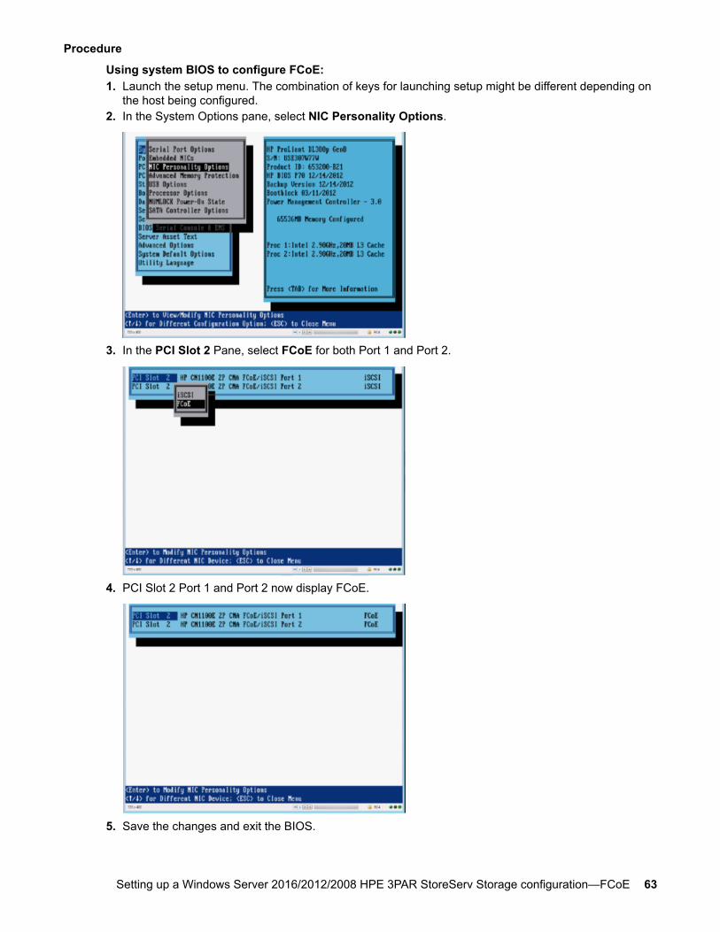
Procedure
Using system BIOS to configure FCoE:1. Launch the setup menu. The combination of keys for launching setup might be different depending on
the host being configured.2. In the System Options pane, select NIC Personality Options.
3. In the PCI Slot 2 Pane, select FCoE for both Port 1 and Port 2.
4. PCI Slot 2 Port 1 and Port 2 now display FCoE.
5. Save the changes and exit the BIOS.
Setting up a Windows Server 2016/2012/2008 HPE 3PAR StoreServ Storage configuration—FCoE 63
Configuring an HPE 3PAR StoreServ Storage port for ahost connection—FCoE
When setting up the FCoE initiator to FC target, there are no unique requirements for the HPE 3PARStoreServ Storage. The initiator coming from the host adapters through the FCoE Forwarder switch istreated as another FC device connecting to the HPE 3PAR StoreServ Storage ports.
For specific configurations that support FCoE CNAs and forwarder switches, see the appropriate HPE3PAR OS release version on the SPOCK website.
Procedure
1. When a server with a host CNA card configured with FCoE is connected to HPE 3PAR StoreServStorage ports, see:
• Configuring ports on the HPE 3PAR StoreServ Storage—fabric connection—FC on page 15• Setting up a Windows Server 2016/2012/2008 HPE 3PAR StoreServ Storage configuration—
FC on page 302. When setting up an FCoE initiator to FCoE target, the HPE 3PAR StoreServ Storage ports must be
configured for FCoE. See Configuring the HPE 3PAR StoreServ Storage—FCoE on page 26.
More Informationhttp://www.hpe.com/storage/spock
Configuring FCoE initiator to FC targetNOTE:
For complete and detailed instructions for configuring a server with a given Converged NetworkAdapter, see the CNA manufacturer documentation.
After the initiators are logged in to the HPE 3PAR StoreServ Storage target ports, the next processes willbe to create a host definition and provision storage to the host.
If an FCoE to FC configuration is set up, this diagram summarizes the general steps for configuring aCNA and FCoE Forwarder Switch:
64 Configuring an HPE 3PAR StoreServ Storage port for a host connection—FCoE
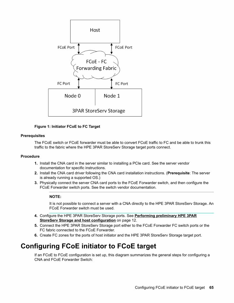
Figure 1: Initiator FCoE to FC Target
Prerequisites
The FCoE switch or FCoE forwarder must be able to convert FCoE traffic to FC and be able to trunk thistraffic to the fabric where the HPE 3PAR StoreServ Storage target ports connect.
Procedure
1. Install the CNA card in the server similar to installing a PCIe card. See the server vendordocumentation for specific instructions.
2. Install the CNA card driver following the CNA card installation instructions. (Prerequisite: The serveris already running a supported OS.)
3. Physically connect the server CNA card ports to the FCoE Forwarder switch, and then configure theFCoE Forwarder switch ports. See the switch vendor documentation.
NOTE:
It is not possible to connect a server with a CNA directly to the HPE 3PAR StoreServ Storage. AnFCoE Forwarder switch must be used.
4. Configure the HPE 3PAR StoreServ Storage ports. See Performing preliminary HPE 3PARStoreServ Storage and host configuration on page 12.
5. Connect the HPE 3PAR StoreServ Storage port either to the FCoE Forwarder FC switch ports or theFC fabric connected to the FCoE Forwarder.
6. Create FC zones for the ports of host initiator and the HPE 3PAR StoreServ Storage target port.
Configuring FCoE initiator to FCoE targetIf an FCoE to FCoE configuration is set up, this diagram summarizes the general steps for configuring aCNA and FCoE Forwarder Switch:
Configuring FCoE initiator to FCoE target 65
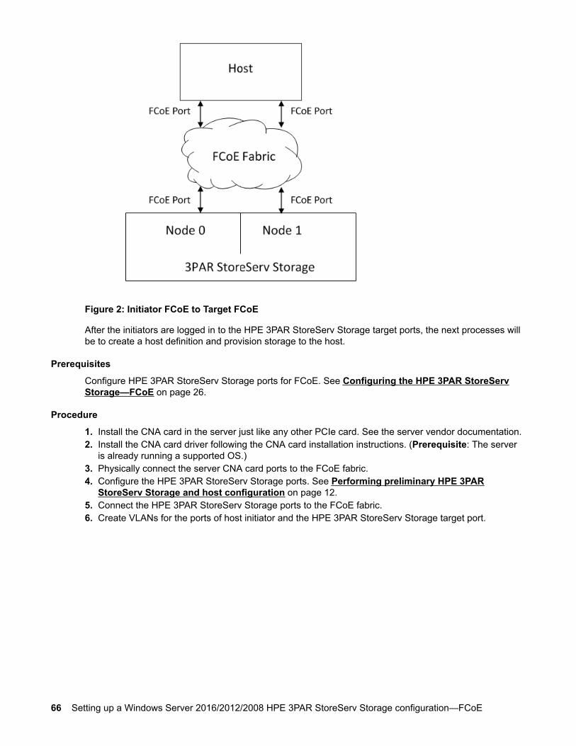
Figure 2: Initiator FCoE to Target FCoE
After the initiators are logged in to the HPE 3PAR StoreServ Storage target ports, the next processes willbe to create a host definition and provision storage to the host.
Prerequisites
Configure HPE 3PAR StoreServ Storage ports for FCoE. See Configuring the HPE 3PAR StoreServStorage—FCoE on page 26.
Procedure
1. Install the CNA card in the server just like any other PCIe card. See the server vendor documentation.2. Install the CNA card driver following the CNA card installation instructions. (Prerequisite: The server
is already running a supported OS.)3. Physically connect the server CNA card ports to the FCoE fabric.4. Configure the HPE 3PAR StoreServ Storage ports. See Performing preliminary HPE 3PAR
StoreServ Storage and host configuration on page 12.5. Connect the HPE 3PAR StoreServ Storage ports to the FCoE fabric.6. Create VLANs for the ports of host initiator and the HPE 3PAR StoreServ Storage target port.
66 Setting up a Windows Server 2016/2012/2008 HPE 3PAR StoreServ Storage configuration—FCoE
Windows Hyper-V Server/HPE 3PARStoreServ Storage configuration setup
The following topics refer to a server with an x64-based processor running an x64 version of WindowsServer:
• Windows Server 2016• Windows Server 2012 R2• Windows Server 2012• Windows Server 2008 R2• Windows Server 2008
For details on Hyper-V operation, see the specific documentation on the Microsoft website.
Required: A hotfix, available from Microsoft, is required to support live storage migrations with WindowsServer 2012 and 2012 R2 using Cluster Shared Volumes on HPE 3PAR OS 3.1.2 and later. The hotfixmust be applied before updating the HPE 3PAR StoreServ Storage.
For more information about the required hotfix, see the Windows Server 2012 SPOCK configuration onthe SPOCK website.
More Informationhttp://www.hpe.com/storage/spock
Hyper-V software installationHyper-V software is installed by installing the Hyper-V Role from the Server Manager.
For system requirements and known issues, search the Microsoft website for the Hyper-V Server GettingStarted Guide for your version of the Hyper-V software. Follow the steps explained there to install theHyper-V management tool, create, and set up a virtual machine, install the operating system andintegration services, and configure virtual networks.
Hyper-V software configurationSearch the Microsoft website for the Microsoft Hyper-V Server Setup and Configuration documentation foryour version of the Hyper-V software, and then follow those setup and configuration instructions.
NOTE:
No particular parameters must be set in the Hyper-V software to work with the HPE 3PAR StoreServStorage. No additional steps are necessary on the HPE 3PAR StoreServ Storage to work with aWindows Hyper-V Server.
Windows Hyper-V Server/HPE 3PAR StoreServ Storage configuration setup 67

Allocating storage for the hostCAUTION:With HPE 3PAR OS 3.1.1 MU2 (and only MU2) with Windows Server 2012 and WindowsServer 2012 R2, for both NTFS and ReFS file systems, run the following command from aPowerShell or CMD window before running a Perform a quick format action on a TPVV in the DiskManagement utility.
NOTE:
These steps are not required with later versions of HPE 3PAR OS other than 3.1.1 MU2 withWindows Server 2012.
Procedure
1. Use the following command:
# fsutil behavior set disabledeletenotify 1
This command disables the delete notifications for all volumes behavior. If you do notrun this command, it will take longer to complete the format operation, and the Disk Management utilitymay become unresponsive if you attempt to interrupt any pending format operations.
2. When all outstanding format operations are successfully complete, run the following command to re-enable the delete notifications for all volumes behavior:
# fsutil behavior set disabledeletenotify 0
Creation of storage on the HPE 3PAR StoreServ StorageThe following topics describe the general procedures and commands that are required to create thevirtual volumes (VVs) that can then be exported for discovery by the host.
For additional information, see the HPE 3PAR Command Line Interface Administrator’s Manual. For acomprehensive description of HPE 3PAR OS commands, see the HPE 3PAR Command Line InterfaceReference at the Hewlett Packard Enterprise Information Library website.
More Informationhttp://www.hpe.com/info/storage/docs
Virtual volumes creationVirtual volumes (VVs) are the only data layer visible to hosts. After setting up a plan for allocating spacefor hosts on the HPE 3PAR StoreServ Storage, create the VVs for eventual export as LUNs to theWindows Server 2016/2012/2008 host.
Create volumes that are provisioned from one or more common provisioning groups (CPGs). Volumescan be either fully provisioned, thinly provisioned, or thinly deduplicated volumes. Optionally, specify aCPG for snapshot space for provisioned volumes.
Virtual volumes are of three types:
68 Allocating storage for the host
• Fully provisioned virtual volumes (FPVVs)• Thinly provisioned virtual volumes (TPVVs)• Thinly provisioned deduplicated virtual volumes (TDVVs)
Thinly provisioned deduplicated virtual volumes
With HPE 3PAR OS 3.2.1 MU1 and later, the HPE 3PAR Thin Deduplication feature is supported. ToTDVVs, an HPE 3PAR Thin Provisioning license is required.
HPE 3PAR Thin Deduplication allows the creation of TDVVs from solid-state drive (SSD) CPGs. A TDVVhas the same characteristics as a TPVV, with the additional capability of removing duplicated data beforeit is written to the volume. The TDVVs are managed like any other TPVV. A TDVV must be associatedwith CPGs created from an SSD.
NOTE:
For Windows Server 2016/2012/2008 servers, Hewlett Packard Enterprise recommends that thedefault NTFS file system allocation size is set to 16 KB when creating NTFS file systems on TDVVsto realize better capacity efficiency on these volumes.
To create FPVVs, TPVVs, or TDVVS, see the following references:
• HPE 3PAR StoreServ Storage Concepts Guide• HPE 3PAR Command Line Interface Administrator’s Manual• HPE 3PAR Command Line Interface Reference
These documents are available at the Hewlett Packard Enterprise Information Library.
Creating virtual volumes—HPE 3PAR MC 4.7To create a virtual volume in the HPE Management Console, access the Create Virtual Volume wizard.This wizard allows you to create Thinly Deduped, Thinly Provisioned, and Fully Provisioned volumes.
For more information, see the HPE 3PAR Management Console 4.7 User Guide at the Hewlett PackardEnterprise Information Library website.
Procedure
1. In the Manager Pane, select Provisioning.2. In the Common Actions pane, click Create Virtual Volume. The Create Virtual Volume wizard
appears.
Creating virtual volumes—HPE 3PAR SSMC 2.4For more information, see the HPE 3PAR StoreServ Management Console 2.4 User Guide at the HewlettPackard Enterprise Information Library website.
Procedure
1. On the main menu, select Block Persona > Virtual Volume.2. Click + Create virtual volume or select Create on the Actions menu.3. Follow the instructions on the dialog that opens and select one of the following virtual volume options:
Creating virtual volumes—HPE 3PAR MC 4.7 69
• Full—A fully provisioned virtual volume is one in which the space that is allocated at creation timeis the full capacity (size) of the virtual volume.
• Thin—A thinly provisioned virtual volume is one in which a minimal amount of the space isallocated at creation time. After the virtual volume is exported to a host, the virtual volume sizegrows automatically with the host writes, up to the user-defined size limit.
• Dedup—A thinly deduplicated virtual volume is a thinly provisioned virtual volume with in-linededuplication. In-line deduplication eliminates duplicate writes to help extend the life of SSDphysical drives.
Creating virtual volumes—HPE 3PAR CLIThe createvv command creates volumes that are provisioned from one or more common provisioninggroups. Volumes can be fully provisioned from a CPG or can be thinly provisioned. Users can optionallyspecify a CPG for snapshot space for fully provisioned volumes and thinly provisioned volumes.
For more information, see the HPE 3PAR OS Command Line Interface Reference at the Hewlett PackardEnterprise Information Library website.
Procedure
1. Create a fully provisioned or TPVV using the syntax:
cli % createvv [options] <usr_CPG> <VV_name> [.<index>] <size>[g|G|t|T]
For example:
cli % createvv -cnt 5 testcpg TESTLUNS 5g
More Informationhttp://www.hpe.com/info/storage/docs
Exporting VLUNs to the host
Procedure
1. Follow the instructions for creating virtual volumes (VVs) and virtual LUNs (VLUNs) in the HPE 3PARCommand-Line Administrator’s Guide available at the Hewlett Packard Enterprise Information Librarywebsite.
Observe the following guidelines:
• Sparse LUNs are supported (you can skip LUN IDs).• You can export LUNs in nonascending order (for example, 0, 5, 7, 3).• In most cases, Windows Server 2016/2012/2008 register only LUNs 0 to 255, although the HPE
3PAR StoreServ Storage can export LUNs 0 to 65535. Limitations are imposed when using MPIOand presenting storage to Hyper-V virtual machines and by the iSCSI initiator. Refer to MicrosoftWindows documentation for more information.
• For FC, Windows can recognize up to 254 LUN IDs per target.
70 Creating virtual volumes—HPE 3PAR CLI
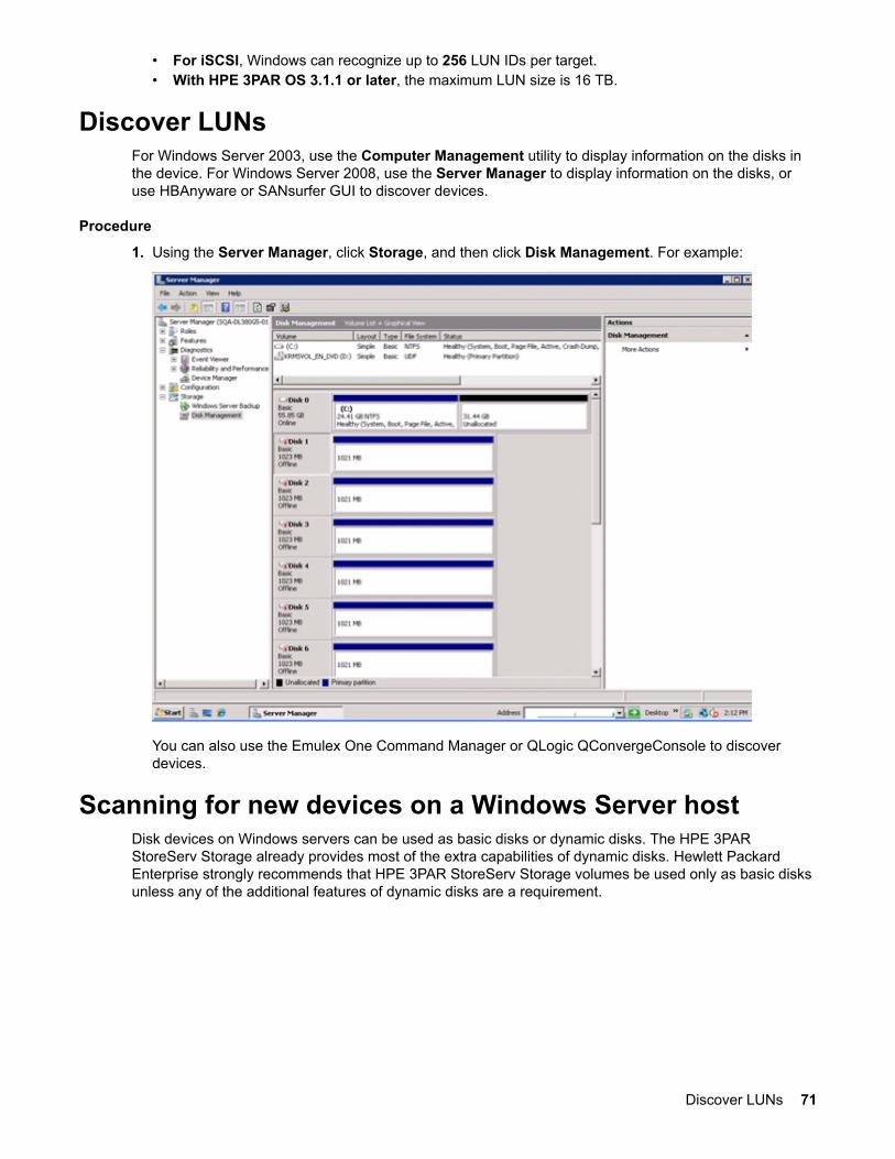
• For iSCSI, Windows can recognize up to 256 LUN IDs per target.• With HPE 3PAR OS 3.1.1 or later, the maximum LUN size is 16 TB.
Discover LUNsFor Windows Server 2003, use the Computer Management utility to display information on the disks inthe device. For Windows Server 2008, use the Server Manager to display information on the disks, oruse HBAnyware or SANsurfer GUI to discover devices.
Procedure
1. Using the Server Manager, click Storage, and then click Disk Management. For example:
You can also use the Emulex One Command Manager or QLogic QConvergeConsole to discoverdevices.
Scanning for new devices on a Windows Server hostDisk devices on Windows servers can be used as basic disks or dynamic disks. The HPE 3PARStoreServ Storage already provides most of the extra capabilities of dynamic disks. Hewlett PackardEnterprise strongly recommends that HPE 3PAR StoreServ Storage volumes be used only as basic disksunless any of the additional features of dynamic disks are a requirement.
Discover LUNs 71
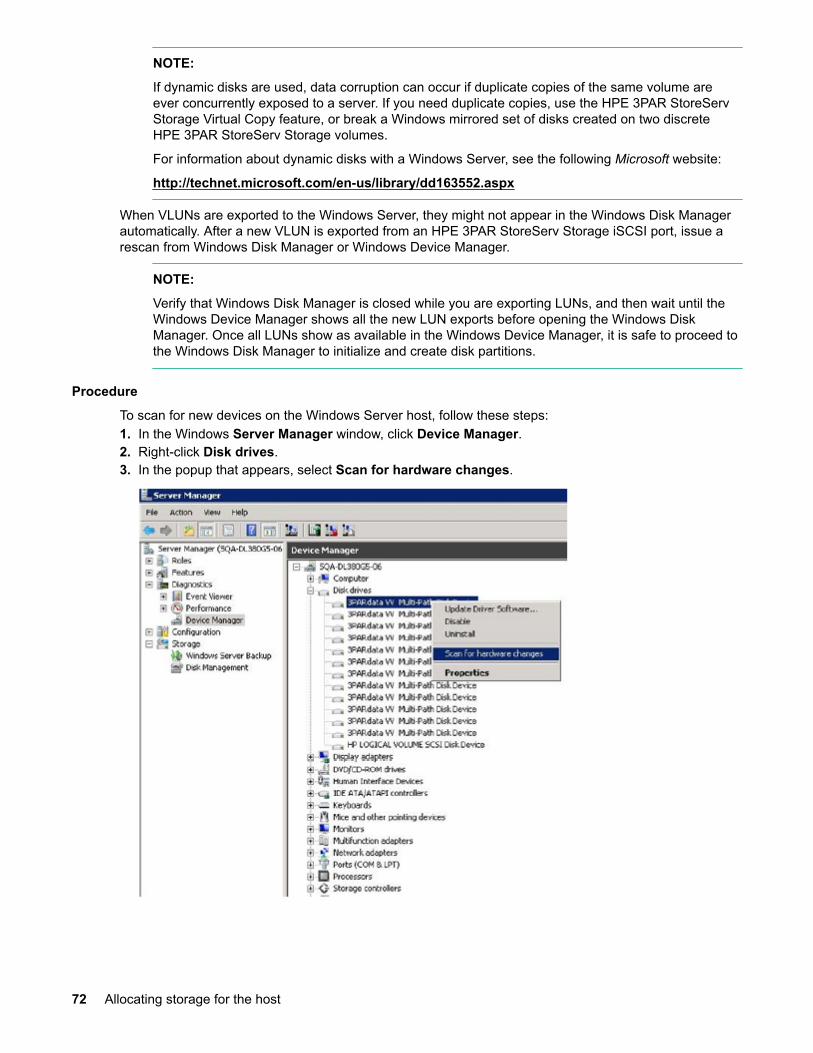
NOTE:
If dynamic disks are used, data corruption can occur if duplicate copies of the same volume areever concurrently exposed to a server. If you need duplicate copies, use the HPE 3PAR StoreServStorage Virtual Copy feature, or break a Windows mirrored set of disks created on two discreteHPE 3PAR StoreServ Storage volumes.
For information about dynamic disks with a Windows Server, see the following Microsoft website:
http://technet.microsoft.com/en-us/library/dd163552.aspx
When VLUNs are exported to the Windows Server, they might not appear in the Windows Disk Managerautomatically. After a new VLUN is exported from an HPE 3PAR StoreServ Storage iSCSI port, issue arescan from Windows Disk Manager or Windows Device Manager.
NOTE:
Verify that Windows Disk Manager is closed while you are exporting LUNs, and then wait until theWindows Device Manager shows all the new LUN exports before opening the Windows DiskManager. Once all LUNs show as available in the Windows Device Manager, it is safe to proceed tothe Windows Disk Manager to initialize and create disk partitions.
Procedure
To scan for new devices on the Windows Server host, follow these steps:1. In the Windows Server Manager window, click Device Manager.2. Right-click Disk drives.3. In the popup that appears, select Scan for hardware changes.
72 Allocating storage for the host
Removing a storage volume from the hostProcedure
1. To remove a volume from the Windows Server host, follow standard Microsoft administrativeprocedures for removing a volume, and follow the HPE 3PAR StoreServ Storage standard procedureto remove a volume.
NOTE:
Removing a disk from a Windows Server host does not erase the data on the disk. If there isconcern about the data on the disk, consider using a third-party utility that erases the data on thedisk before removing it from the Windows Server host.
SCSI UNMAP primitive support for Windows Server2016/2012
HPE 3PAR OS 3.1.1 introduced support for the UNMAP storage primitive (operation code 42h) which issupported by Windows Server 2012 and later with the NTFS file system. UNMAP causes the HPE 3PARStoreServ Storage to reclaim storage space on a thinly provisioned virtual volume (TPVV) or a thinlydeduplicated virtual volume (TDVV) when data or files are deleted on a supported file system type. Thisfeature is useful in maintaining the volume as a thin volume with no storage disk space allocated for filesthat are deleted.
NOTE:
Currently, the Windows Server 2012 and Windows Server 2012 R2 Resilient Filesystem (ReFS)does not take advantage of space reclaimed from files deleted using the UNMAP primitive on thinlyprovisioned LUNs.
ODX support for Windows Server 2016/2012HPE 3PAR OS 3.1.2 introduces support for offloaded data transfer (ODX), which is supported byWindows Server 2012 and Windows Server 2012 R2 with the NTFS file system.
Beginning with HPE 3PAR OS 3.2.2 MU3 and 3.2.1 MU5, support for offloaded data transfer (ODX)extends to Windows Server 2016.
In a traditional file transfer/copy operation between two LUNs on the same storage array, buffered-readand buffered-write operations would be used on the host to complete the request. With arrays thatsupport ODX, supported Windows versions can complete the request by offloading the file transfer to thestorage array. By doing so, ODX minimizes latencies, maximizes array throughput, and reduces resourceusage such as CPU and network consumption on the host computer. Windows Server offloads filetransfers transparently and automatically when you move or copy files, regardless of whether you drag-and-drop files through File Explorer or use the command-line file copy commands. For more informationabout ODX, see the following Microsoft website:
technet.microsoft.com/en-us/library/hh831628.aspx
Removing a storage volume from the host 73
Booting from the HPE 3PAR StoreServ StorageNOTE:
For details about connecting the HPE 3PAR StoreServ Storage to the host, see Performingpreliminary HPE 3PAR StoreServ Storage and host configuration on page 12.
Configuring for iSCSI SAN bootHardware iSCSI SAN Boot is supported on Windows Server 2012 and Windows Server 2008 R2 SP1with HPE 3PAR StoreServ 20000, 10000, 8000, and 7000 Storage systems.
For more information about supported configurations, see the Storage Single Point of ConnectivityKnowledge (SPOCK).
NOTE:
For SAN boot with hardware iSCSI using Emulex CNAs, do not use a LUN ID higher than 4 as theboot LUN. This setting is a requirement of the Emulex BIOS. Failing to do this action may result inthe host issues when attempting to SAN boot.
For more information, see vendor-specific documentation.
For configurations that have iSCSI connections on Windows Server 2008, the Double-Take Flex softwareis required.
NOTE:
iSCSI SAN Boot using Double-Take Flex software is not supported on Windows Server 2012.
See the latest version of the Double-Take Flex User’s Guide for full instructions.
NOTE:
The rest of this chapter consists of instructions for configuring for an HPE 3PAR StoreServ Storageboot with FC storage.
More Informationhttp://www.hpe.com/storage/spock
Configuring the BIOS for FC SAN bootThis topic explains specific host HBA settings required for booting from an HPE 3PAR StoreServ Storagein a fabric configuration. Use the Boot BIOS version listed on the SPOCK website.
To obtain a copy of this documentation, go to the following page of the Hewlett PackardEnterprise Support Center website.
NOTE:
With the introduction of the Microsoft Storport driver, booting from a Storage Area Network (SAN)has become less problematic. See the Microsoft support document Support for booting from aStorage Area Network (SAN):
support.microsoft.com/kb/305547
74 Booting from the HPE 3PAR StoreServ Storage
More Informationhttp://www.hpe.com/support/hpeschttp://www.hpe.com/storage/spock
Configuring for an HPE 3PAR StoreServ Storage boot—Emulex HBA
Procedure
1. Boot the Windows Server system following the instructions in the BootBios update manual.2. Press Alt+E.
For each Emulex adapter, set the following parameters:
a. Select Configure the Adapter's Parameters.b. Select Enable or Disable the BIOS. For SAN boot, ensure that the BIOS is enabled.c. Press Esc to return to the previous menu.d. Select Auto Scan Setting; set the parameter to First LUN 0 Device. To return to the previous
menu, press Esc .e. Select Topology.f. Select Fabric Point to Point for fabric configurations.g. Select FC-AL for direct connect configurations.
3. To return to the previous menu to set up other adapters, press Esc.4. When you are finished, press x to exit and restart.
Configuring for an HPE 3PAR StoreServ Storage boot—QLogic HBAUse the QLogic HBA Fast!UTIL utility to configure the HBA. Follow these steps:
Procedure
1. Boot the Windows Server host, and as it is booting, press the Alt+Q or Ctrl+Q keys when the HBABIOS prompts appear.
2. In the Fast!UTIL utility, click Select Host Adapter, and then select the appropriate adapter.3. Click Configuration Settings > Adapter Settings.4. In the Adapter Settings window, set the following:
• Host Adapter BIOS: Enabled• Spinup Delay: Disabled• Connection Option: 0 for direct connect or 1 for fabric
NOTE:
Record the Adapter Port Name WWPN for creating the host definition. See Creating the hostdefinition for an HPE 3PAR StoreServ Storage boot—FC on page 76.
5. To exit this window, press Esc .6. Click Selectable Boot Settings. In the Selectable Boot Settings window, set Selectable Boot
Device to Disabled.7. Press Esc twice to exit; when you are asked whether to save NVRAM settings, click Yes.8. Exit Fast!UTIL.
Configuring for an HPE 3PAR StoreServ Storage boot—Emulex HBA 75
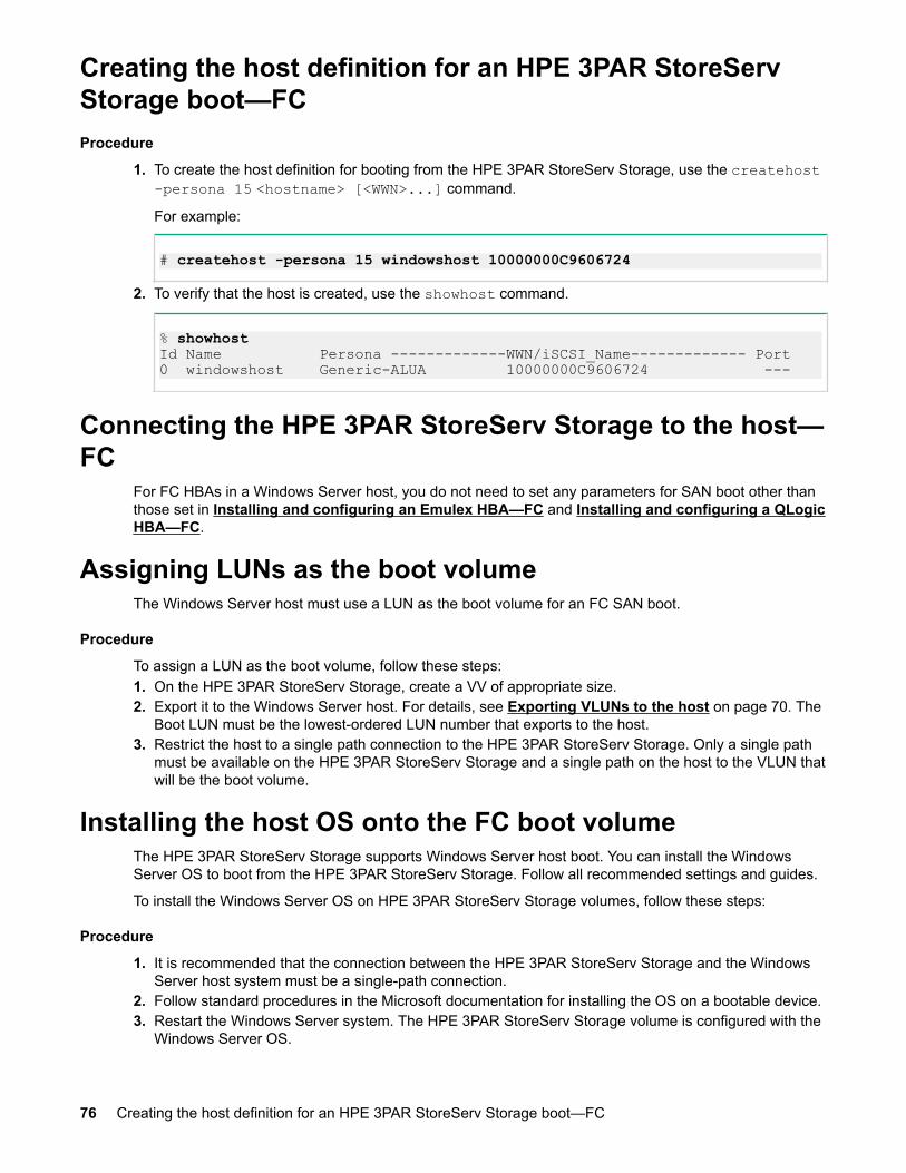
Creating the host definition for an HPE 3PAR StoreServStorage boot—FCProcedure
1. To create the host definition for booting from the HPE 3PAR StoreServ Storage, use the createhost-persona 15 <hostname> [<WWN>...] command.
For example:
# createhost -persona 15 windowshost 10000000C9606724
2. To verify that the host is created, use the showhost command.
% showhostId Name Persona -------------WWN/iSCSI_Name------------- Port 0 windowshost Generic-ALUA 10000000C9606724 ---
Connecting the HPE 3PAR StoreServ Storage to the host—FC
For FC HBAs in a Windows Server host, you do not need to set any parameters for SAN boot other thanthose set in Installing and configuring an Emulex HBA—FC and Installing and configuring a QLogicHBA—FC.
Assigning LUNs as the boot volumeThe Windows Server host must use a LUN as the boot volume for an FC SAN boot.
Procedure
To assign a LUN as the boot volume, follow these steps:1. On the HPE 3PAR StoreServ Storage, create a VV of appropriate size.2. Export it to the Windows Server host. For details, see Exporting VLUNs to the host on page 70. The
Boot LUN must be the lowest-ordered LUN number that exports to the host.3. Restrict the host to a single path connection to the HPE 3PAR StoreServ Storage. Only a single path
must be available on the HPE 3PAR StoreServ Storage and a single path on the host to the VLUN thatwill be the boot volume.
Installing the host OS onto the FC boot volumeThe HPE 3PAR StoreServ Storage supports Windows Server host boot. You can install the WindowsServer OS to boot from the HPE 3PAR StoreServ Storage. Follow all recommended settings and guides.
To install the Windows Server OS on HPE 3PAR StoreServ Storage volumes, follow these steps:
Procedure
1. It is recommended that the connection between the HPE 3PAR StoreServ Storage and the WindowsServer host system must be a single-path connection.
2. Follow standard procedures in the Microsoft documentation for installing the OS on a bootable device.3. Restart the Windows Server system. The HPE 3PAR StoreServ Storage volume is configured with the
Windows Server OS.
76 Creating the host definition for an HPE 3PAR StoreServ Storage boot—FC

Connecting multiple paths for FC SAN bootAfter the Windows Server host completely boots up and is online, connect additional paths to the fabric orthe HPE 3PAR StoreServ Storage system directly by completing the following tasks.
Procedure
1. On the HPE 3PAR StoreServ Storage, issue createhost -add <hostname> <WWN> to add theadditional paths to the defined HPE 3PAR StoreServ Storage host definition.
2. On the Windows Server host, rescan for devices. See Scanning for new devices on a WindowsServer host on page 71.
3. Restart the Windows Server system.
Connecting multiple paths for FC SAN boot 77

Using failover clustering with Microsoft MPIOThe HPE 3PAR StoreServ Storage supports failover clustering.
Procedure
1. Set up the cluster according to Microsoft recommendations.
78 Using failover clustering with Microsoft MPIO
Using failover clustering in a virtualizedenvironment
The HPE 3PAR StoreServ Storage supports failover clustering on some VMware ESX/ESXi virtualizedenvironments as guest OS clustering. For the purposes of setup and configuration, such an environmentis to be considered a VMware ESX configuration.
Setup of the host ESX/ESXi servers must be in accordance with the HPE 3PAR VMware ESX/ESXiImplementation Guide available at the Hewlett Packard Enterprise Information Library website.
For additional information on the configuration of a Windows Server 2016/2012/2008 failover clusterwithin a set of virtual machines on VMware ESX, see VMware KB-000269-02 (for ESX/ESXi 4.0) orVMware KB-000271-00 (for ESX/ESXi 4.1).
More Informationhttp://www.hpe.com/info/storage/docs
Using failover clustering in a virtualized environment 79

HPE 3PAR All Flash ArrayStarting with HPE 3PAR OS 3.2.1, HPE 3PAR introduced All-Flash-Arrays that deliver significantimprovements in performance, density, resiliency, and data mobility.
Applications like OLTP, VDI, business analytics and various other data services are taking advantage ofthe improvements that these HPE 3PAR All-Flash-Arrays offer. To benefit from these improvements, noarray special settings are needed.
For more information on HPE 3PAR All-Flash-Arrays, see the white paper HPE 3PAR StoreServ:Optimized for Flash available at the Hewlett Packard Enterprise Storage Information Library website.
NOTE:
• Windows 2012 and 2016 hosts will identify various volume provisioning and file system types asdifferent "Media Types" in the "Optimize Drives" menu and will exhibit varying behavior afteroptimization. The following table designates the "Media Type" in the "Optimize Drives" menu andthe expected status after optimization:
Filesystem Type ProvisioningType
"OptimizeDrives" MediaTypeIdentificationWindows2012R2 and2016
Status AfterOptimizationWindows2012R2
Status AfterOptimizationWindows 2016
NTFS Thin Provisioned Thin ProvisionedDrive
OK OK
ReFS Thin Provisioned Thin ProvisionedDrive
Optimization notavailable
OK
NTFS Full Provisioned Solid-State Drive Optimization notavailable
Optimization notavailable
ReFS Full Provisioned Solid-State Drive Optimization notavailable
Optimization notavailable
• For volumes on All-Flash-Arrays, executing a utility or command which defragments or attemptsto optimize data placement should be avoided. Such actions unnecessarily contribute to solid-state drive (SSD) device wear. Unlike spinning media, an SSD device inherently has norotational latency and, therefore, defragmentation or optimization provides no benefit. As towhether data management commands recognize SSD devices, consult the documentation or thevendor for your host OS and adjust their behavior accordingly.
• SSD devices do not benefit from optimization and contribute to SSD device wear. Therefore,HPE 3PAR recommends not to run drive optimization.
80 HPE 3PAR All Flash Array
HPE 3PAR File PersonaStarting with HPE 3PAR OS 3.2.1 MU2, the HPE 3PAR File Persona software is available. TheHPE 3PAR File Persona software provides file services and access to file storage by network protocolssuch as:
• Server Message Block (SMB)• Network file system (NFS)• Web Distributed Authoring and Versioning (WebDAV)
For information on supported HPE 3PAR StoreServ Storage models and client configurations, see theSPOCK website: SPOCK Home > Explore Storage Interoperability With SPOCK > Explore 3PARStoreServ Storage interoperability > Explore 3PAR File Persona interoperability.
For a complete description of the HPE 3PAR File Persona software, including required setup andguidelines, see the HPE 3PAR File Persona User Guide available at the Hewlett Packard EnterpriseInformation Library Storage website.
More Informationhttp://www.hpe.com/storage/spockhttp://www.hpe.com/info/storage/docs
HPE 3PAR File Persona 81

Mounting NFS File Shares in File ServicesUsing CLI CommandsProcedure
1. See the Windows Server documentation for the deployed version of Windows to configure the IPinterfaces on the host.
NOTE:
The requirements for configuring Windows Server clients to use File Services provided by the3PAR StoreServ Storage are no different from using other network file systems. For more detailson configuring hosts, see the Windows documentation.
2. Issue the showvfs command to look up the IP address of the Virtual File Server created in FileServices:
cli% showvfs
VFS FPG IPAddr State -Comment-vfs11 fpg11 10.10.1.114 normal -vfs02 fpg02 10.10.1.113 normal -vfs12 fpg12 10.10.1.115 normal -------------------------------------- 4 total
3. Lookup the share path of the NFS share you are mounting by using the showfshare nfs -dcommand.
4. In this example: File Provisioning group = fpg1, Virtual File server = vfs1, File Store = fstore1, NFSshare = share 1, Share Directory = share_dir were created in File Services. The full directory path inthe example indicates the path to mount the share. Options in the example show the current options ofthe share. The default options for a share are: sync, auth_nlm, wdelay, sec=sys,no_all_squash, crossmnt, secure_subtree_check, hide, root_squash, ro.
cli% showfshare nfs -d
Share Name : fshare11File Provisioning Group : fpg11Virtual File Server : vfs11File Store : fstore11Share Directory : sharedir11Full Directory Path : /fpg11/vfs11/fstore11/sharedir11State : normalClients : *Options : no_all_squash, no_root_squash, crossmnt, rw, hide, sync, auth_nlm, secure, sec=sys, wdelay, subtree_checkComment : ---
5. On the Windows Server host, use the mount command to mount the share. By default, both Solaris 10and 11 versions mount in NFS version 4. To mount in NFS version 3, use vers=3 instead of vers=4.
82 Mounting NFS File Shares in File Services Using CLI Commands
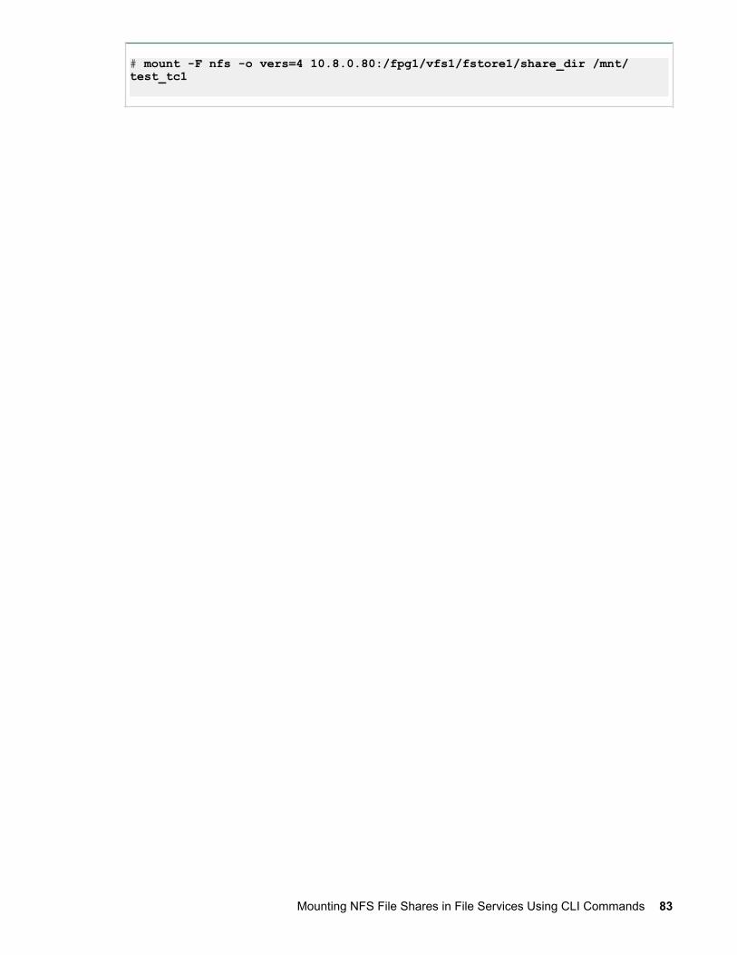
# mount -F nfs -o vers=4 10.8.0.80:/fpg1/vfs1/fstore1/share_dir /mnt/test_tc1
Mounting NFS File Shares in File Services Using CLI Commands 83
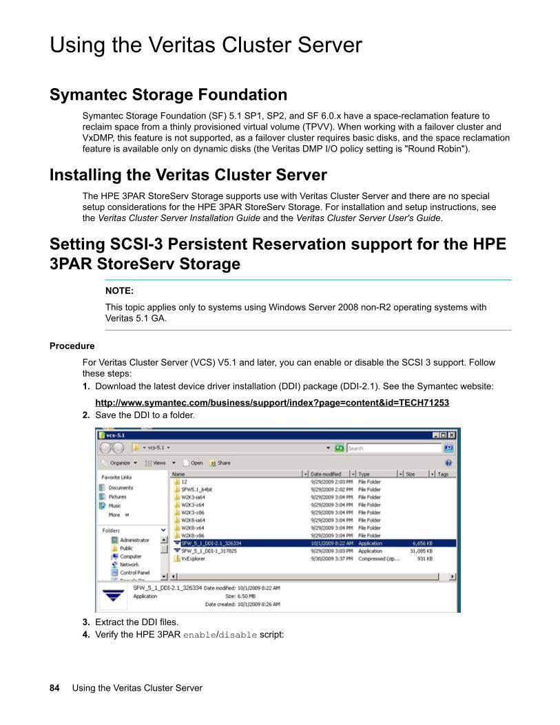
Using the Veritas Cluster Server
Symantec Storage FoundationSymantec Storage Foundation (SF) 5.1 SP1, SP2, and SF 6.0.x have a space-reclamation feature toreclaim space from a thinly provisioned virtual volume (TPVV). When working with a failover cluster andVxDMP, this feature is not supported, as a failover cluster requires basic disks, and the space reclamationfeature is available only on dynamic disks (the Veritas DMP I/O policy setting is "Round Robin").
Installing the Veritas Cluster ServerThe HPE 3PAR StoreServ Storage supports use with Veritas Cluster Server and there are no specialsetup considerations for the HPE 3PAR StoreServ Storage. For installation and setup instructions, seethe Veritas Cluster Server Installation Guide and the Veritas Cluster Server User's Guide.
Setting SCSI-3 Persistent Reservation support for the HPE3PAR StoreServ Storage
NOTE:
This topic applies only to systems using Windows Server 2008 non-R2 operating systems withVeritas 5.1 GA.
Procedure
For Veritas Cluster Server (VCS) V5.1 and later, you can enable or disable the SCSI 3 support. Followthese steps:1. Download the latest device driver installation (DDI) package (DDI-2.1). See the Symantec website:
http://www.symantec.com/business/support/index?page=content&id=TECH712532. Save the DDI to a folder.
3. Extract the DDI files.4. Verify the HPE 3PAR enable/disable script:
84 Using the Veritas Cluster Server
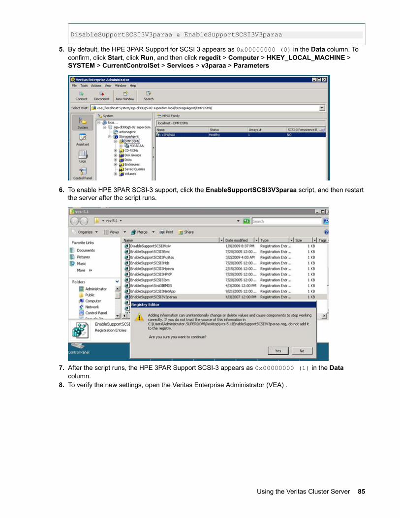
DisableSupportSCSI3V3paraa & EnableSupportSCSI3V3paraa
5. By default, the HPE 3PAR Support for SCSI 3 appears as 0x00000000 (0) in the Data column. Toconfirm, click Start, click Run, and then click regedit > Computer > HKEY_LOCAL_MACHINE >SYSTEM > CurrentControlSet > Services > v3paraa > Parameters
6. To enable HPE 3PAR SCSI-3 support, click the EnableSupportSCSI3V3paraa script, and then restartthe server after the script runs.
7. After the script runs, the HPE 3PAR Support SCSI-3 appears as 0x00000000 (1) in the Datacolumn.
8. To verify the new settings, open the Veritas Enterprise Administrator (VEA) .
Using the Veritas Cluster Server 85
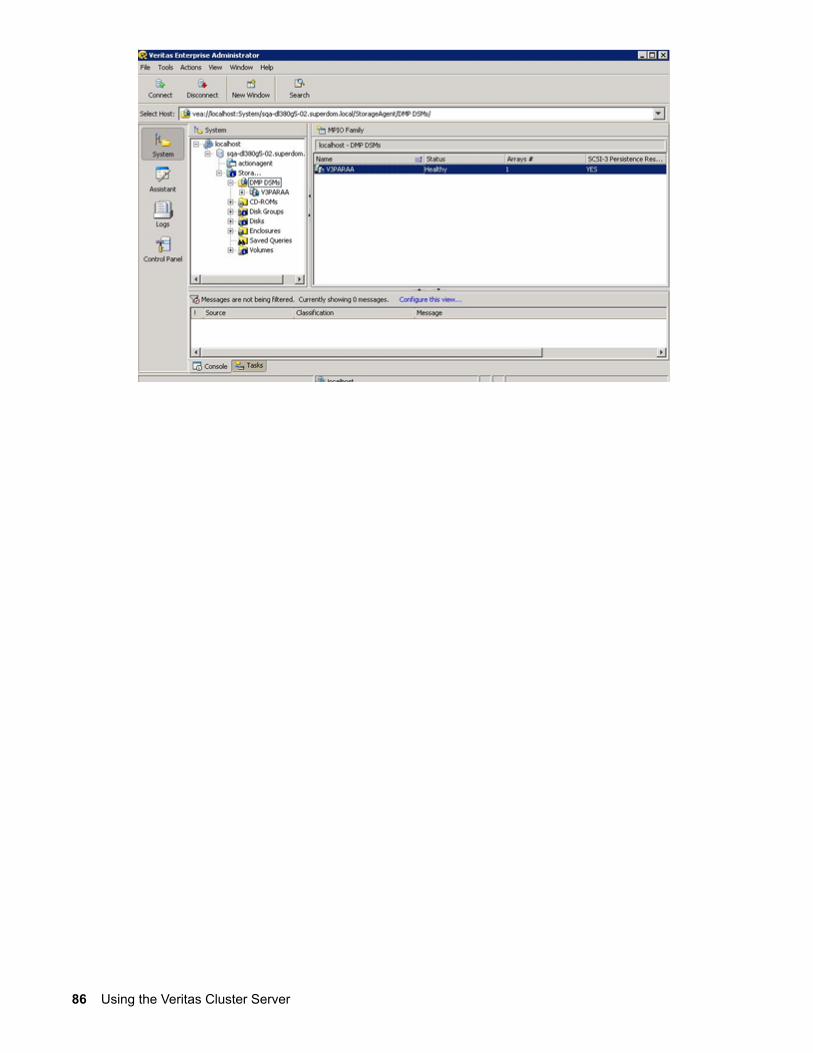
86 Using the Veritas Cluster Server

Installing Veritas DMP
Installing Veritas DMP 87
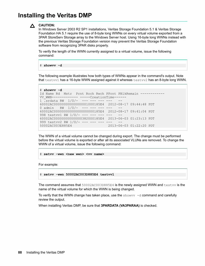
Installing the Veritas DMPCAUTION:In Windows Server 2003 R2 SP1 installations, Veritas Storage Foundation 5.1 & Veritas StorageFoundation HA 5.1 require the use of 8-byte long WWNs on every virtual volume exported from a3PAR StoreServ Storage array to the Windows Server host. Using 16-byte long WWNs instead withthe previous Veritas Storage Foundation version may prevent the Veritas Storage Foundationsoftware from recognizing 3PAR disks properly.
To verify the length of the WWN currently assigned to a virtual volume, issue the followingcommand:
# showvv -d
The following example illustrates how both types of WWNs appear in the command's output. Notethat testvv1 has a 16-byte WWN assigned against it whereas testvv2 has an 8-byte long WWN.
# showvv -dId Name Rd Mstr Prnt Roch Rwch PPrnt PBlkRemain ------------ VV_WWN------------- -----CreationTime------1 .srdata RW 1/0/- --- --- --- --- -- 60002AC00000000000000001000185E4 2012-08-17 09:44:48 PDT0 admin RW 1/0/- --- --- --- --- -- 60002AC00000000000000000000185E4 2012-08-17 09:41:04 PDT998 testvv1 RW 1/0/- --- --- --- --- -- 60002AC00000000000000382000185E4 2013-06-03 01:23:13 PDT999 testvv2 RW 1/0/- --- --- --- --- -- 50002AC003E885E4 2013-06-03 01:22:20 PDT
The WWN of a virtual volume cannot be changed during export. The change must be performedbefore the virtual volume is exported or after all its associated VLUNs are removed. To change theWWN of a virtual volume, issue the following command:
# setvv -wwn <new wwn> <vv name>
For example:
# setvv -wwn 50002AC003D885E4 testvv1
The command assumes that 50002AC003D885E4 is the newly assigned WWN and testvv is thename of the virtual volume for which the WWN is being changed.
To verify that the WWN change has taken place, use the showvv -d command and carefullyreview the output.
When installing Veritas DMP, be sure that 3PARDATA (VA3PARAA) is checked.
88 Installing the Veritas DMP

Installing Veritas DMP 89
WebsitesGeneral websites
Hewlett Packard Enterprise Information Librarywww.hpe.com/info/EIL
Single Point of Connectivity Knowledge (SPOCK) Storage compatibility matrixwww.hpe.com/storage/spock
Storage white papers and analyst reportswww.hpe.com/storage/whitepapers
For additional websites, see Support and other resources.
90 Websites
Support and other resources
Accessing Hewlett Packard Enterprise Support• For live assistance, go to the Contact Hewlett Packard Enterprise Worldwide website:
http://www.hpe.com/assistance• To access documentation and support services, go to the Hewlett Packard Enterprise Support Center
website:
http://www.hpe.com/support/hpesc
Information to collect
• Technical support registration number (if applicable)• Product name, model or version, and serial number• Operating system name and version• Firmware version• Error messages• Product-specific reports and logs• Add-on products or components• Third-party products or components
Accessing updates• Some software products provide a mechanism for accessing software updates through the product
interface. Review your product documentation to identify the recommended software update method.• To download product updates:
Hewlett Packard Enterprise Support Centerwww.hpe.com/support/hpesc
Hewlett Packard Enterprise Support Center: Software downloadswww.hpe.com/support/downloads
Software Depotwww.hpe.com/support/softwaredepot
• To subscribe to eNewsletters and alerts:
www.hpe.com/support/e-updates• To view and update your entitlements, and to link your contracts and warranties with your profile, go to
the Hewlett Packard Enterprise Support Center More Information on Access to Support Materialspage:
www.hpe.com/support/AccessToSupportMaterials
IMPORTANT:
Access to some updates might require product entitlement when accessed through the HewlettPackard Enterprise Support Center. You must have an HPE Passport set up with relevantentitlements.
Support and other resources 91
Customer self repairHewlett Packard Enterprise customer self repair (CSR) programs allow you to repair your product. If aCSR part needs to be replaced, it will be shipped directly to you so that you can install it at yourconvenience. Some parts do not qualify for CSR. Your Hewlett Packard Enterprise authorized serviceprovider will determine whether a repair can be accomplished by CSR.
For more information about CSR, contact your local service provider or go to the CSR website:
http://www.hpe.com/support/selfrepair
Remote supportRemote support is available with supported devices as part of your warranty or contractual supportagreement. It provides intelligent event diagnosis, and automatic, secure submission of hardware eventnotifications to Hewlett Packard Enterprise, which will initiate a fast and accurate resolution based on yourproduct's service level. Hewlett Packard Enterprise strongly recommends that you register your device forremote support.
If your product includes additional remote support details, use search to locate that information.
Remote support and Proactive Care informationHPE Get Connected
www.hpe.com/services/getconnectedHPE Proactive Care services
www.hpe.com/services/proactivecareHPE Proactive Care service: Supported products list
www.hpe.com/services/proactivecaresupportedproductsHPE Proactive Care advanced service: Supported products list
www.hpe.com/services/proactivecareadvancedsupportedproducts
Proactive Care customer informationProactive Care central
www.hpe.com/services/proactivecarecentralProactive Care service activation
www.hpe.com/services/proactivecarecentralgetstarted
Warranty informationTo view the warranty for your product or to view the Safety and Compliance Information for Server,Storage, Power, Networking, and Rack Products reference document, go to the Enterprise Safety andCompliance website:
www.hpe.com/support/Safety-Compliance-EnterpriseProducts
Additional warranty informationHPE ProLiant and x86 Servers and Options
www.hpe.com/support/ProLiantServers-WarrantiesHPE Enterprise Servers
www.hpe.com/support/EnterpriseServers-WarrantiesHPE Storage Products
www.hpe.com/support/Storage-Warranties
92 Customer self repair
HPE Networking Productswww.hpe.com/support/Networking-Warranties
Regulatory informationTo view the regulatory information for your product, view the Safety and Compliance Information forServer, Storage, Power, Networking, and Rack Products, available at the Hewlett Packard EnterpriseSupport Center:
www.hpe.com/support/Safety-Compliance-EnterpriseProducts
Additional regulatory information
Hewlett Packard Enterprise is committed to providing our customers with information about the chemicalsubstances in our products as needed to comply with legal requirements such as REACH (Regulation ECNo 1907/2006 of the European Parliament and the Council). A chemical information report for this productcan be found at:
www.hpe.com/info/reach
For Hewlett Packard Enterprise product environmental and safety information and compliance data,including RoHS and REACH, see:
www.hpe.com/info/ecodata
For Hewlett Packard Enterprise environmental information, including company programs, productrecycling, and energy efficiency, see:
www.hpe.com/info/environment
Documentation feedbackHewlett Packard Enterprise is committed to providing documentation that meets your needs. To help usimprove the documentation, send any errors, suggestions, or comments to Documentation Feedback([email protected]). When submitting your feedback, include the document title, part number,edition, and publication date located on the front cover of the document. For online help content, includethe product name, product version, help edition, and publication date located on the legal notices page.
Regulatory information 93