hpe proliant dl360 gen9 server - gfk etilizecontent.etilize.com/user-manual/1037108110.pdf ·...
TRANSCRIPT
HPE ProLiant DL360 Gen9 Server Maintenance and Service Guide
Abstract This guide describes identification and maintenance procedures, diagnostic tools, specifications, and requirements for hardware
components and software. This guide is for an experienced service technician. Hewlett Packard Enterprise assumes you are qualified in the
servicing of computer equipment, trained in recognizing hazards in products, and are familiar with weight and stability precautions.
Part Number: 767928-006 March 2016 Edition: 6

© Copyright 2014, 2016 Hewlett Packard Enterprise Development LP
The information contained herein is subject to change without notice. The only warranties for Hewlett Packard Enterprise products and services are set forth in the express warranty statements accompanying such products and services. Nothing herein should be construed as constituting an additional warranty. Hewlett Packard Enterprise shall not be liable for technical or editorial errors or omissions contained herein.
Links to third-party websites take you outside the Hewlett Packard Enterprise website. Hewlett Packard Enterprise has no control over and is not responsible for information outside the Hewlett Packard Enterprise website.
Microsoft® and Windows® are either registered trademarks or trademarks of Microsoft Corporation in the United States and/or other countries.
Intel®, Pentium®, and Itanium® are trademarks of Intel Corporation in the U.S. and other countries.
microSD is a trademark or registered trademark of SD-3C in the United States, other countries or both.
UNIX® is a registered trademark of The Open Group.
NVIDIA® is a trademark of NVIDIA Corporation in the U.S. and other countries.

Contents 3
Contents
Illustrated parts catalog ............................................................................................................................. 5 Mechanical components ........................................................................................................................................... 5 System components ................................................................................................................................................. 8
Removal and replacement procedures ................................................................................................... 16 Required tools ........................................................................................................................................................ 16 Preparation procedures .......................................................................................................................................... 16
Power down the server ................................................................................................................................ 16 Extend the server from the rack .................................................................................................................. 17 Remove the server from the rack ................................................................................................................ 17 Access the product rear panel ..................................................................................................................... 18 Access the Systems Insight Display ............................................................................................................ 18
Safety considerations ............................................................................................................................................. 20 Preventing electrostatic discharge............................................................................................................... 20 Symbols on equipment ................................................................................................................................ 21 Server warnings and cautions ..................................................................................................................... 21
Drive blank ............................................................................................................................................................. 22 Hot-plug SAS/SATA drives and SSDs ................................................................................................................... 22 NVMe drives ........................................................................................................................................................... 22 Power supply blank ................................................................................................................................................ 24 AC power supply .................................................................................................................................................... 24 HPE 750W Flex Slot Hot Plug Battery Backup Module .......................................................................................... 25 Access panel .......................................................................................................................................................... 26 Primary PCI riser cage ........................................................................................................................................... 26 PCIe riser board ..................................................................................................................................................... 27 Secondary PCI riser cage ...................................................................................................................................... 28 Primary PCIe riser blank ........................................................................................................................................ 29 Secondary PCIe riser blank .................................................................................................................................... 30 GPU riser and cable option .................................................................................................................................... 31 Fan module ............................................................................................................................................................ 32 Fan blank ................................................................................................................................................................ 33 8SFF Optical/USB/VGA assembly ......................................................................................................................... 34 4LFF Optical/USB/VGA assembly .......................................................................................................................... 35 8SFF Systems Insight Display ............................................................................................................................... 37 4LFF Systems Insight Display ................................................................................................................................ 38 Location discovery services ear ............................................................................................................................. 39 2SFF SAS/SATA drive cage assembly option ....................................................................................................... 41 2SFF Express Bay drive backplane ....................................................................................................................... 44 4LFF hard drive backplane ..................................................................................................................................... 46 8SFF hard drive backplane .................................................................................................................................... 47 10SFF (6 NVMe + 4 SAS/SATA) Express Bay drive backplane ............................................................................ 48 FlexibleLOM ........................................................................................................................................................... 49 Smart Storage Battery ............................................................................................................................................ 50 Expansion boards ................................................................................................................................................... 51 M.2 SSD enablement board ................................................................................................................................... 52 DIMMs .................................................................................................................................................................... 53 Heatsink ................................................................................................................................................................. 54 High-performance heatsink .................................................................................................................................... 55 Processor ............................................................................................................................................................... 56 System battery ....................................................................................................................................................... 59 System board ......................................................................................................................................................... 60 HP Trusted Platform Module .................................................................................................................................. 65
Troubleshooting ...................................................................................................................................... 67 Troubleshooting resources ..................................................................................................................................... 67
Contents 4
Diagnostic tools ...................................................................................................................................... 68 Product QuickSpecs ............................................................................................................................................... 68 Active Health System ............................................................................................................................................. 68 HPE iLO ................................................................................................................................................................. 69
HPE ProLiant Pre-boot Health Summary .................................................................................................... 69 Integrated Management Log ....................................................................................................................... 70
Component identification ........................................................................................................................ 71 Front panel components ......................................................................................................................................... 71 Front panel LEDs and buttons ................................................................................................................................ 72
UID button functionality ............................................................................................................................... 73 Power fault LEDs ......................................................................................................................................... 74
Systems Insight Display LEDs ............................................................................................................................... 74 Systems Insight Display LED combinations ........................................................................................................... 75 Rear panel components ......................................................................................................................................... 76 Rear panel LEDs and buttons ................................................................................................................................ 77 Flex slot battery backup module LEDs and buttons ............................................................................................... 78 System board components ..................................................................................................................................... 79
System maintenance switch ........................................................................................................................ 80 NMI jumper .................................................................................................................................................. 80 DIMM slots................................................................................................................................................... 81 Non-hot-plug PCI riser board slot definitions ............................................................................................... 81
Device numbers ..................................................................................................................................................... 82 Hot-plug drive LED definitions ..................................................................................................................... 83 NVMe SSD components.............................................................................................................................. 83
Hot-plug fans .......................................................................................................................................................... 84
Cabling .................................................................................................................................................... 86 Cabling overview .................................................................................................................................................... 86 2SFF embedded SATA backplane cabling ............................................................................................................ 86 4LFF Universal Media Bay cabling ......................................................................................................................... 87 8SFF Universal Media Bay cabling ........................................................................................................................ 88 10SFF (6 NVMe + 4 SAS/SATA) Express Bay Enablement Option cabling .......................................................... 89 Smart Array controller cabling ................................................................................................................................ 90 Embedded SATA cabling ....................................................................................................................................... 91 M.2 SSD Enablement Board option cabling ........................................................................................................... 92 GPU cabling ........................................................................................................................................................... 93
Specifications .......................................................................................................................................... 94 Environmental specifications .................................................................................................................................. 94 Server specifications .............................................................................................................................................. 94 Power supply specifications ................................................................................................................................... 95
HPE 500W Flex Slot Platinum Hot-plug Power Supply ............................................................................... 95 HPE 800W Flex Slot Platinum Hot-plug Power Supply ............................................................................... 96 HPE 800W Flex Slot Titanium Plus Hot-plug Power Supply ....................................................................... 96 HPE 800W Flex Slot Universal Hot-plug Power Supply .............................................................................. 97 HPE 800W Flex Slot -48VDC Hot-plug Power Supply ................................................................................ 97 HPE 1400W Flex Slot Platinum Plus Hot-plug Power Supply ..................................................................... 98
HPE 750W Flex Slot Hot-plug Battery Backup Module .......................................................................................... 99 Hot-plug power supply calculations ........................................................................................................................ 99
Acronyms and abbreviations................................................................................................................. 100
Documentation feedback ...................................................................................................................... 103
Index ..................................................................................................................................................... 104

Illustrated parts catalog 5
Illustrated parts catalog
Mechanical components Hewlett Packard Enterprise continually improves and changes product parts. For complete and current supported parts information, see the Hewlett Packard Enterprise PartSurfer website (http://www.hpe.com/info/partssurfer).
Item Description Spare part number
Customer self repair
1 Access panel 775425-001 Mandatory1
2 PCI riser blank — —
a) PCI riser blank, full height 775431-001 Mandatory1
b) PCI riser blank, low profile 785499-001 Mandatory1
3 PCI riser cage — —
a) PCI riser cage, standard primary 775421-001 Optional2
b) PCI riser cage, secondary, full height* 775419-001 Optional2
c) PCI riser cage, secondary, low profile* 775420-001 Optional2
4 Miscellaneous blanks kit* 775423-001
a) Power supply blank — Mandatory1
b) Heatsink blank — Mandatory1
c) Fan blank — Mandatory1
d) FlexibleLOM blank — Mandatory1

Illustrated parts catalog 6
Item Description Spare part number
Customer self repair
5 Standard right ear 775417-001 Mandatory1
6 Standard left ear 795214-001 Mandatory1
Rack mounting hardware — —
7 Rack mounting hardware kit* — —
a) SFF Easy Install Rail 744111-001 Mandatory1
b) LFF Easy Install Rail 744112-001 Mandatory1
c) SFF Ball Bearing Rail 675042-001 Mandatory1
d) LFF Ball Bearing Rail 675041-001 Mandatory1
8 Cable management arm* — —
a) Cable management arm, easy install 744113-001 Mandatory1
b) Cable management arm, ball bearing 675043-001 Mandatory1
*Not shown 1Mandatory—Parts for which customer self repair is mandatory. If you request Hewlett Packard Enterprise to replace these parts, you will be charged for the travel and labor costs of this service. 2Optional—Parts for which customer self repair is optional. These parts are also designed for customer self repair. If, however, you require that Hewlett Packard Enterprise replace them for you, there may or may not be additional charges, depending on the type of warranty service designated for your product. 3No—Some Hewlett Packard Enterprise parts are not designed for customer self repair. In order to satisfy the customer warranty, Hewlett Packard Enterprise requires that an authorized service provider replace the part. These parts are identified as "No" in the Illustrated Parts Catalog. 1Obligatoire—Pièces pour lesquelles le client doit procéder lui-même aux réparations. Si vous demandez à Hewlett Packard Enterprise de procéder au remplacement de ces pièces, les frais de transport et de main d’œuvre pour ce service vous seront facturés. 2Facultatif—Pièces pour lesquelles une réparation par le client est facultative. Ces pièces sont également conçues pour que le client puisse procéder lui-même aux réparations. Cependant, les frais supplémentaires engendrés par le remplacement de ces pièces par Hewlett Packard Enterprise dépendent du type de service de garantie désigné pour votre produit. 3Non—Certaines pièces Hewlett Packard Enterprise ne sont pas conçues pour être remplacées par le client. Afin de se conformer aux exigences de la garantie la garantie du client, Hewlett Packard Enterprise demande à un fournisseur de services agréé de procéder au remplacement de la pièce. Ces pièces sont signaléespar le mot « Non » dans le Catalogue de pièces illustré. 1Obbligatorio—Parti per le quali il cliente è tenuto a effettuare autonomamente la riparazione. Se si richiede l'intervento di Hewlett Packard Enterprise per la sostituzione di queste parti, al cliente verranno addebitate le spese di viaggio e manodopera dell'operazione. 2Facoltativo—Parti per le quali la riparazione in autonomia da parte del cliente è facoltativa. Queste parti sono progettate per consentire anche la riparazione da parte del cliente. Tuttavia, se il cliente richiedel'intervento di Hewlett Packard Enterprise per la sostituzione, potrebbero essere addebitate spese aggiuntive a seconda del tipo di garanzia in assistenza previsto per il prodotto. 3No—Alcune parti Hewlett Packard Enterprise non sono progettate la riparazione in autonomia da parte del cliente. In base a quanto previsto dalla garanzia per il cliente, Hewlett Packard Enterprise richiede l'intervento di un tecnico autorizzato per la sostituzione della parte. Queste parti sono contrassegnate con"No"nel catalogo parti illustrato. 1Zwingend—Teile, für die das Customer Self Repair-Verfahren zwingend vorgegeben ist. Wenn Sie den Austausch dieser Teile von Hewlett Packard Enterprisevornehmen lassen, werden Ihnen die Anfahrt- und Arbeitskosten für diesen Service berechnet. 2Optional—Teile, für die das Customer Self Repair-Verfahren optional ist. Diese Teile sind auch für Customer Self Repair ausgelegt. Wenn Sie jedoch den Austausch dieser Teile von Hewlett Packard Enterprisevornehmen lassen möchten, können bei diesem Service je nach den für Ihr Produkt vorgesehenen Garantiebedingungen zusätzliche Kosten anfallen.

Illustrated parts catalog 7
3Nein—Einige Hewlett Packard Enterprise Teile sind nicht für Customer Self Repair ausgelegt. Um den Garantieanspruch des Kunden zu erfüllen, muss das Teil von einem Hewlett Packard Enterprise Servicepartner ersetzt werden. Im illustrierten Teilekatalog sind diese Teile mit „No“ bzw. „Nein“ gekennzeichnet. 1Obligatorio—Componentes cuya reparación por parte del usuario es obligatoria. Si solicita a Hewlett Packard Enterprise que realice la sustitución de estos componentes, tendrá que hacerse cargo de los gastos de desplazamiento y de mano de obra de dicho servicio. 2Opcional—Componentes cuya reparación por parte del usuario es opcional. Estos componentes también están diseñados para que puedan ser reparados por el usuario. Sin embargo, si precisa que Hewlett Packard Enterprise realice su sustitución, puede o no conllevar costes adicionales, dependiendo del tipo de servicio de garantía correspondiente al producto. 3No—Algunos componentes de Hewlett Packard Enterprise no están diseñados para que puedan ser reparados por el usuario. Para que el usuario haga valer su garantía, Hewlett Packard Enterprise pone como condición que un proveedor de servicios autorizado realice la sustitución de estos componentes. Dichos componentes se identifican con la palabra "No" en el catálogo ilustrado de componentes. 1Verplicht—Onderdelen die de klant zelf moet vervangen. Als u Hewlett Packard Enterprise vraagt deze onderdelen te vervangen, worden er reis- en arbeidskosten voor deze service in rekening gebracht. 2Optioneel—Onderdelen die de klant zelf kan vervangen. Deze onderdelen zijn ook ontworpen om door de klant zelf te worden vervangen. Als u Hewlett Packard Enterprise verzoekt om deze te vervangen, kan het zijn dat hiervoor extra kosten in rekening worden gebracht, afhankelijk van het soort garantie dat op uw product van toepassing is. 3Geen—Sommige onderdelen van Hewlett Packard Enterprise zijn niet ontworpen om door de klant zelf te worden vervangen. Om te voldoen aan de garantievoorwaarden eist Hewlett Packard Enterprise dat een geautoriseerde serviceverlener het onderdeel vervangt. Deze onderdelen worden aangeduid met 'Geen' in de geïllustreerde onderdelencatalogus. 1Obrigatório—Peças cujo reparo feito pelo cliente é obrigatório. Se desejar que a Hewlett Packard Enterprise substitua essas peças, serão cobradas as despesas de transporte e mão-de-obra do serviço. 2Opcional—Peças cujo reparo feito pelo cliente é opcional. Essas peças também são projetadas para o reparo feito pelo cliente. No entanto, se desejar que a Hewlett Packard Enterprise as substitua, pode haver ou não a cobrança de taxa adicional, dependendo do tipo de serviço de garantia destinado ao produto. 3Não—Algumas peças da Hewlett Packard Enterprise não são projetadas para o reparo feito pelo cliente. A fim de cumprir a garantia do cliente, a Hewlett Packard Enterprise exige que um técnico autorizado substitua a peça. Essas peças estão identificadas com a marca "No" (Não), no catálogo de peças ilustrado.

Illustrated parts catalog 8
System components Hewlett Packard Enterprise continually improves and changes product parts. For complete and current supported parts information, see the Hewlett Packard Enterprise PartSurfer website (http://www.hpe.com/info/partssurfer).
Item Description Spare part number
Customer self repair
9 PCIe riser boards — —
a) Primary PCIe riser board 785497-001 Optional2
b) Low-profile Secondary PCIe riser board* 785498-001 Optional2
c) Full-height Secondary PCIe riser board* 775419-001 Optional2
10 Controller options — —
a) HPE Smart Array P440ar Controller 775413-001 Mandatory1
b) HPE Smart Array P440ar Controller with cut heatsink* 786760-001 Mandatory1
c) HPE H240ar Smart Host Bus Adapter* 749997-001 Mandatory1
d) HPE Smart Array P840ar Controller* 848147-001 Mandatory1
11 Heatsink — —
a) Standard efficiency heatsink 775403-001 Optional2
b) High-performance heatsink* 775404-001 Optional2
12 Processor — —
a) 1.90-GHz Intel Xeon E5-2609 v3 processor* ** 762443-001 Optional2
b) 2.40-GHz Intel Xeon E5-2620 v3 processor* ** 762445-001 Optional2
c) 2.60-GHz Intel Xeon E5-2640 v3 processor* ** 762447-001 Optional2
d) 2.60-GHz Intel Xeon E5-2660 v3 processor* ** 762449-001 Optional2

Illustrated parts catalog 9
Item Description Spare part number
Customer self repair
e) 2.30-GHz Intel Xeon E5-2670 v3 processor* ** 762450-001 Optional2
f) 2.50-GHz Intel Xeon E5-2680 v3 processor* ** 762451-001 Optional2
g) 2.60-GHz Intel Xeon E5-2690 v3 processor 762452-001 Optional2
h) 2.00-GHz Intel Xeon E5-2683 v3 processor* ** 762453-001 Optional2
i) 2.30-GHz Intel Xeon E5-2695 v3 processor* ** 762454-001 Optional2
j) 3.50-GHz Intel Xeon E5-2637 v3 processor* ** 762455-001 Optional2
k) 3.40-GHz Intel Xeon E5-2643 v3 processor* ** 762456-001 Optional2
l) 3.20-GHz Intel Xeon E5-2667 v3 processor* ** 762457-001 Optional2
m) 3.10-GHz Intel Xeon E5-2687W v3 processor* ** 762458-001 Optional2
n) 1.80-GHz Intel Xeon E5-2630L v3 processor* ** 762459-001 Optional2
o) 2.60-GHz Intel Xeon E5-2697 v3 processor* ** 765154-001 Optional2
p) 2.30-GHz Intel Xeon E5-2698 v3 processor* ** 780760-001 Optional2
q) 2.30-GHz Intel Xeon E5-2699 v3 processor* ** 780761-001 Optional2
r) 3.00-GHz Intel Xeon E5-2623v3 processor* ** 780762-001 Optional2
s) 1.70-GHz Intel Xeon E5-2603 v4 processor** 835599-001 Optional2
t) 1.70-GHz Intel Xeon E5-2609 v4 processor* ** 835600-001 Optional2
u) 2.40-GHz Intel Xeon E5-2620 v4 processor* ** 835601-001 Optional2
v) 2.20-GHz Intel Xeon E5-2630 v4 processor* ** 835602-001 Optional2
w) 2.40-GHz Intel Xeon E5-2640 v4 processor* ** 835603-001 Optional2
x) 2.20-GHz Intel Xeon E5-2650 v4 processor* ** 835604-001 Optional2
y) 2.00-GHz Intel Xeon E5-2660 v4 processor* ** 835605-001 Optional2
z) 2.40-GHz Intel Xeon E5-2680 v4 processor* ** 835606-001 Optional2
aa) 2.60-GHz Intel Xeon E5-2690 v4 processor* ** 835607-001 Optional2
bb) 1.80-GHz Intel Xeon E5-2630L v4 processor* ** 835608-001 Optional2
cc) 1.70-GHz Intel Xeon E5-2650L v4 processor* ** 835609-001 Optional2
dd) 2.60-GHz Intel Xeon E5-2623 v4 processor* ** 835610-001 Optional2
ee) 3.40-GHz Intel Xeon E5-2637 v4 processor* ** 835611-001 Optional2
ff) 3.20-GHz Intel Xeon E5-2643 v4 processor* ** 835612-001 Optional2
gg) 2.90-GHz Intel Xeon E5-2667 v4 processor* ** 835613-001 Optional2
hh) 2.10-GHz Intel Xeon E5-2683 v4 processor* ** 835614-001 Optional2
ii) 2.10-GHz Intel Xeon E5-2695 v4 processor* ** 835615-001 Optional2
jj) 2.30-GHz Intel Xeon E5-2697 v4 processor* ** 835616-001 Optional2
ll) 3.00-GHz Intel Xeon E5-2687W v4 processor* ** 841034-001 Optional2

Illustrated parts catalog 10
Item Description Spare part number
Customer self repair
13 DIMM — —
a) 8-GB, 1Rx4, PC4-2133R 774170-001 Mandatory1
b) 8-GB, 2Rx8, PC4-2133R* 774171-001 Mandatory1
c) 16-GB, 2Rx4, PC4-2133R* 774172-001 Mandatory1
d) 16-GB, 2Rx4, PC4-2133L* 774173-001 Mandatory1
e) 32-GB, 4Rx4, PC4-2133L* 774174-001 Mandatory1
f) 8-GB, 1Gx8, PC4-2400R* 852545-001 Mandatory1
g) 8-GB, 1Gx8, PC4-2400R* 819410-001 Mandatory1
h) 16-GB, 1Gx4, PC4-2400R* 846740-001 Mandatory1
i) 16-GB, 2Gx4, PC4-2400R* 819411-001 Mandatory1
j) 32-GB, 2Gx4, PC4-2400R* 819412-001 Mandatory1
k) 64-GB, 2Gx4, PC4-2400L* 819413-001 Mandatory1
l) 32-GB, 2Gx4, PC4-2400L* 819414-001 Mandatory1
14 System board assembly — —
a) System board assembly 775400-001 Optional2
b) System board assembly- BRDWL 843307-001 Optional2
15 Hot plug fans — —
a) Standard fan module 775415-001 Mandatory1
b) High-efficiency fan module* 775416-001 Mandatory1
16 Hot-plug power supplies — —
a) 500 W, Flex Slot Platinum 754377-001 Mandatory1
b) 800 W, Flex Slot Platinum* 754381-001 Mandatory1
c) 800 W, Flex Slot Titanium* 754378-001 Mandatory1
d) 800 W, Flex Slot Universal* 754379-001 Mandatory1
e) 800 W, Flex Slot –48Vdc* 754382-001 Mandatory1
f) 1400 W, Flex Slot Platinum* 754383-001 Mandatory1
17 HPE 750W Flex Slot Hot-Plug Battery Backup Module 754380-001 Mandatory1
18 Hot-plug drives — —
a) 146-GB, SAS, SFF, 15,000-rpm, 6G 653950-001 Mandatory1
b) 300-GB, SAS, SFF, 10,000-rpm, 6G* 653955-001 Mandatory1
c) 450-GB, SAS, SFF, 10,000-rpm, 6G* 653956-001 Mandatory1
d) 500-GB, SAS, SFF, 7,200-rpm, 6G* 653953-001 Mandatory1
e) 600-GB, SAS, SFF, 10,000-rpm, 6G* 653957-001 Mandatory1
f) 900-GB, SAS, SFF, 10,000-rpm, 6G* 653971-001 Mandatory1
g) 1-TB, SAS, SFF, 7,200-rpm, 6G* 653954-001 Mandatory1

Illustrated parts catalog 11
Item Description Spare part number
Customer self repair
h) 1-TB, SAS, LFF, 7,200-rpm, 6G* 653947-001 Mandatory1
i) 1.2-TB, SAS, SFF, 10,000-rpm, 6G* 718292-001 Mandatory1
j) 2-TB, SAS, LFF, 7,200-rpm, 6G* 653948-001 Mandatory1
k) 3-TB, SAS, LFF, 7,200-rpm, 6G* 653959-001 Mandatory1
l) 500-GB, SATA, LFF, 7,200-rpm, 6G* 658103-001 Mandatory1
m) 1-TB, SATA, SFF, 7,200-rpm, 6G* 656108-001 Mandatory1
n) 1-TB, SATA, LFF, 7,200-rpm, 6G* 657739-001 Mandatory1
o) 2-TB, SATA, LFF, 7,200-rpm, 6G* 658102-001 Mandatory1
p) 3-TB, SATA, LFF, 7,200-rpm, 6G* 628182-001 Mandatory1
q) 4-TB, SATA, LFF, 7,200-rpm, 6G* 693720-001 Mandatory1
19 Solid state drives, SAS* — —
a) 200-GB, SAS, ME, SFF, 12G 741224-001 Mandatory1
b) 200-GB, SAS, HE, SFF, 12G 741230-001 Mandatory1
c) 400-GB, SAS, ME, SFF, 12G 741226-001 Mandatory1
d) 400-GB, SAS, HE, SFF, 12G 741232-001 Mandatory1
e) 800-GB, SAS, VE, SFF, 12G 762749-001 Mandatory1
f) 800-GB, SAS, ME, SFF, 12G 741228-001 Mandatory1
g) 800-GB, SAS, HE, SFF, 12G 741234-001 Mandatory1
h) 800-GB, SAS, VE, LFF, 12G 762750-001 Mandatory1
i) 800-GB, SAS, ME, LFF, 12G* 692163-001 Mandatory1
j) 1.6-TB, SAS, VE, SFF, 12G 762751-001 Mandatory1
k) 1.6-TB, SAS, VE, LFF, 12G 762752-001 Mandatory1
20 Solid state drives, SATA* — —
a) 80-GB, SATA, VE, SFF, 6G 734562-001 Mandatory1
b) 80-GB, SATA, VE, SFF, 6G 734563-001 Mandatory1
c) 100-GB, SATA, ME, SFF, 6G 692164-001 Mandatory1
d) 100-GB, SATA, ME, LFF, 6G 692160-001 Mandatory1
e) 120-GB, SATA, VE, SFF, 6G 718163-001 Mandatory1
f) 120-GB, SATA, VE, LFF, 6G 718300-001 Mandatory1
g) 200-GB, SATA, ME, SFF, 6G 692165-001 Mandatory1
h) 200-GB, SATA, ME, LFF, 6G 692161-001 Mandatory1
i) 240-GB, SATA, VE, SFF, 6G 718137-001 Mandatory1
j) 240-GB, SATA, VE, LFF, 6G 718294-001 Mandatory1
k) 300-GB, SATA, VE, SFF, 6G 739954-001 Mandatory1

Illustrated parts catalog 12
Item Description Spare part number
Customer self repair
l) 300-GB, SATA, VE, LFF, 6G 739955-001 Mandatory1
m) 400-GB, SATA, ME, SFF, 6G 692166-001 Mandatory1
n) 400-GB, SATA, ME, LFF, 6G 692162-001 Mandatory1
o) 480-GB, SATA, VE, SFF, 6G 718138-001 Mandatory1
p) 480-GB, SATA, VE, LFF, 6G 718296-001 Mandatory1
q) 600-GB, SATA, VE, SFF, 6G 739959-001 Mandatory1
r) 600-GB, SATA, VE, LFF, 6G 739960-001 Mandatory1
s) 800-GB, SATA, VE, SFF, 6G 718139-001 Mandatory1
t) 800-GB, SATA, VE, LFF, 6G 718298-001 Mandatory1
u) 800-GB, SATA, ME, SFF, 6G 692167-001 Mandatory1
v) 800-GB, SATA, ME, LFF, 6G 692163-001 Mandatory1
21 Solid state drives, NVMe* — —
a) 400-GB, NVMe, VE, SFF 765076-001 Mandatory1
b) 400-GB, NVMe, LE, SFF 765063-001 Mandatory1
c) 400-GB, NVMe, ME, SFF 765059-001 Mandatory1
d) 800-GB, NVMe, LE, SFF 765064-001 Mandatory1
e) 800-GB, NVMe, ME, SFF 765060-001 Mandatory1
f) 1.2-TB, NVMe, VE, SFF 765068-001 Mandatory1
g) 1.6-TB, NVMe, LE, SFF 765065-001 Mandatory1
h) 1.6-TB, NVMe, ME, SFF 765061-001 Mandatory1
i) 2.0-TB, NVMe, VE, SFF 765069-001 Mandatory1
j) 2.0-TB, NVMe, LE, SFF 765066-001 Mandatory1
k) 2.0-TB, NVMe, ME, SFF 765062-001 Mandatory1
22 Systems Insight Display power switch modules — —
a) SFF Systems Insight Display power switch module* 775418-001 Mandatory1
b) LFF Systems Insight Display power switch module* 775412-001 Mandatory1
23 Backplane boards — —
a) 8SFF backplane board* 780428-001 Optional2
b) 2SFF backplane board* 775401-001 Optional2
c) 4LFF backplane board* 775402-001 Optional2
d) 2SFF Express Bay drive backplane* 812791-001 Optional2
e) 10SFF (6 NVMe + 4 SAS/SATA) Express Bay drive backplane and drive cage*
823792-001 Optional2
24 HPE Express Bay Bridge Card* 824019-001 Optional2
25 GPU options — —
Illustrated parts catalog 13
Item Description Spare part number
Customer self repair
a) NVIDIA Quadro K2200 3GB GPU* 783874-001 Mandatory1
b) NVIDIA Quadro K4200 4GB GPU* 783875-001 Mandatory1
c) NVIDIA Quadro M4000 8GB GPU* 841576-001 Mandatory1
26 Standard cabled power switch modules — —
a) SFF Standard cabled power switch module* 783290-001 Mandatory1
b) LFF Standard cabled power switch module* 783291-001 Mandatory1
27 HPE Smart Storage Battery* 815983-001 Mandatory1
28 Optical media assemblies — —
a) SFF DVD-RW/USB/VGA assembly* 775427-001 Mandatory1
b) SFF USB/VGA assembly* 775426-001 Mandatory1
c) LFF USB/VGA assembly* 775411-001 Mandatory1
29 M.2 SSD enablement board — —
a) HPE 120GB M.2 SSD Enablement Board* 797908-001 Mandatory1
b) HPE Dual 120GB M.2 SSD Enablement Board* 797907-001 Mandatory1
30 Cables — —
a) 8SFF power cable* 780418-001 Mandatory1
b) 4LFF power cable* 780423-001 Mandatory1
c) 8SFF x4 Mini-SAS cable for P440ar, H240ar, and H240 for Slot 1*
780421-001 Mandatory1
d) 8SFF Embedded SATA cable* 780420-001 Mandatory1
e) 8SFF x8 Mini-SAS cable for P840ar, P440, and P840 for Slot 1*
780421-001 Mandatory1
f) 4LFF Embedded SATA cable* 780424-001 Mandatory1
g) 4LFF x4 Mini-SAS cable for P440ar and H240ar* 780425-001 Mandatory1
h) 2SFF H240ar internal SAS cable* 787305-001 Mandatory1
i) 2SFF P440ar internal SAS cable* 787306-001 Mandatory1
j) 8SFF P440ar internal SAS cable* 787307-001 Mandatory1
k) 4LFF P440ar internal SAS cable* 787308-001 Mandatory1
l) GPU cable, secondary riser* 780426-001 Mandatory1
m) GPU cable, primary riser* 780427-001 Mandatory1
*Not shown **All processors in this HPE ProLiant server must have the same cache size, speed, number of cores, and rated maximum power consumption. 1Mandatory—Parts for which customer self repair is mandatory. If you request Hewlett Packard Enterprise to replace these parts, you will be charged for the travel and labor costs of this service. 2Optional—Parts for which customer self repair is optional. These parts are also designed for customer self repair. If, however, you require that Hewlett Packard Enterprise replace them for you, there may or may not be additional charges, depending on the type of warranty service designated for your product. 3No—Some Hewlett Packard Enterprise parts are not designed for customer self repair. In order to satisfy the customer warranty, Hewlett Packard Enterprise requires that an authorized service provider replace the part. These parts are identified as "No" in the Illustrated Parts Catalog.

Illustrated parts catalog 14
1Obligatoire—Pièces pour lesquelles le client doit procéder lui-même aux réparations. Si vous demandez à Hewlett Packard Enterprise de procéder au remplacement de ces pièces, les frais de transport et de main d’œuvre pour ce service vous seront facturés. 2Facultatif—Pièces pour lesquelles une réparation par le client est facultative. Ces pièces sont également conçues pour que le client puisse procéder lui-même aux réparations. Cependant, les frais supplémentaires engendrés par le remplacement de ces pièces par Hewlett Packard Enterprise dépendent du type de service de garantie désigné pour votre produit. 3Non—Certaines pièces Hewlett Packard Enterprise ne sont pas conçues pour être remplacées par le client. Afin de se conformer aux exigences de la garantie la garantie du client, Hewlett Packard Enterprise demande à un fournisseur de services agréé de procéder au remplacement de la pièce. Ces pièces sont signaléespar le mot « Non » dans le Catalogue de pièces illustré. 1Obbligatorio—Parti per le quali il cliente è tenuto a effettuare autonomamente la riparazione. Se si richiede l'intervento di Hewlett Packard Enterprise per la sostituzione di queste parti, al cliente verranno addebitate le spese di viaggio e manodopera dell'operazione. 2Facoltativo—Parti per le quali la riparazione in autonomia da parte del cliente è facoltativa. Queste parti sono progettate per consentire anche la riparazione da parte del cliente. Tuttavia, se il cliente richiedel'intervento di Hewlett Packard Enterprise per la sostituzione, potrebbero essere addebitate spese aggiuntive a seconda del tipo di garanzia in assistenza previsto per il prodotto. 3No—Alcune parti Hewlett Packard Enterprise non sono progettate la riparazione in autonomia da parte del cliente. In base a quanto previsto dalla garanzia per il cliente, Hewlett Packard Enterprise richiede l'intervento di un tecnico autorizzato per la sostituzione della parte. Queste parti sono contrassegnate con"No"nel catalogo parti illustrato. 1Zwingend—Teile, für die das Customer Self Repair-Verfahren zwingend vorgegeben ist. Wenn Sie den Austausch dieser Teile von Hewlett Packard Enterprisevornehmen lassen, werden Ihnen die Anfahrt- und Arbeitskosten für diesen Service berechnet. 2Optional—Teile, für die das Customer Self Repair-Verfahren optional ist. Diese Teile sind auch für Customer Self Repair ausgelegt. Wenn Sie jedoch den Austausch dieser Teile von Hewlett Packard Enterprisevornehmen lassen möchten, können bei diesem Service je nach den für Ihr Produkt vorgesehenen Garantiebedingungen zusätzliche Kosten anfallen. 3Nein—Einige Hewlett Packard Enterprise Teile sind nicht für Customer Self Repair ausgelegt. Um den Garantieanspruch des Kunden zu erfüllen, muss das Teil von einem Hewlett Packard Enterprise Servicepartner ersetzt werden. Im illustrierten Teilekatalog sind diese Teile mit „No“ bzw. „Nein“ gekennzeichnet. 1Obligatorio—Componentes cuya reparación por parte del usuario es obligatoria. Si solicita a Hewlett Packard Enterprise que realice la sustitución de estos componentes, tendrá que hacerse cargo de los gastos de desplazamiento y de mano de obra de dicho servicio. 2Opcional—Componentes cuya reparación por parte del usuario es opcional. Estos componentes también están diseñados para que puedan ser reparados por el usuario. Sin embargo, si precisa que Hewlett Packard Enterprise realice su sustitución, puede o no conllevar costes adicionales, dependiendo del tipo de servicio de garantía correspondiente al producto. 3No—Algunos componentes de Hewlett Packard Enterprise no están diseñados para que puedan ser reparados por el usuario. Para que el usuario haga valer su garantía, Hewlett Packard Enterprise pone como condición que un proveedor de servicios autorizado realice la sustitución de estos componentes. Dichos componentes se identifican con la palabra "No" en el catálogo ilustrado de componentes. 1Verplicht—Onderdelen die de klant zelf moet vervangen. Als u Hewlett Packard Enterprise vraagt deze onderdelen te vervangen, worden er reis- en arbeidskosten voor deze service in rekening gebracht. 2Optioneel—Onderdelen die de klant zelf kan vervangen. Deze onderdelen zijn ook ontworpen om door de klant zelf te worden vervangen. Als u Hewlett Packard Enterprise verzoekt om deze te vervangen, kan het zijn dat hiervoor extra kosten in rekening worden gebracht, afhankelijk van het soort garantie dat op uw product van toepassing is. 3Geen—Sommige onderdelen van Hewlett Packard Enterprise zijn niet ontworpen om door de klant zelf te worden vervangen. Om te voldoen aan de garantievoorwaarden eist Hewlett Packard Enterprise dat een geautoriseerde serviceverlener het onderdeel vervangt. Deze onderdelen worden aangeduid met 'Geen' in de geïllustreerde onderdelencatalogus. 1Obrigatório—Peças cujo reparo feito pelo cliente é obrigatório. Se desejar que a Hewlett Packard Enterprise substitua essas peças, serão cobradas as despesas de transporte e mão-de-obra do serviço. 2Opcional—Peças cujo reparo feito pelo cliente é opcional. Essas peças também são projetadas para o reparo feito pelo cliente. No entanto, se desejar que a Hewlett Packard Enterprise as substitua, pode haver ou não a cobrança de taxa adicional, dependendo do tipo de serviço de garantia destinado ao produto. 3Não—Algumas peças da Hewlett Packard Enterprise não são projetadas para o reparo feito pelo cliente. A fim de cumprir a garantia do cliente, a Hewlett Packard Enterprise exige que um técnico autorizado substitua a peça. Essas peças estão identificadas com a marca "No" (Não), no catálogo de peças ilustrado.

Illustrated parts catalog 15

Removal and replacement procedures 16
Removal and replacement procedures
Required tools You need the following items for some procedures:
• T-10/T-15 Torx screwdriver
• HPE Insight Diagnostics software
Preparation procedures To access some components and perform certain service procedures, you must perform one or more of the following procedures:
• Extend the server from the rack (on page 17). If you are performing service procedures in a Hewlett Packard Enterprise, Compaq branded, Telco, or third-party rack cabinet, you can use the locking feature of the rack rails to support the server and gain access to internal components. For more information about Telco rack solutions, refer to the RackSolutions.com website (http://www.racksolutions.com/hpe).
• Power down the server (on page 16). If you must remove a server from a rack or a non-hot-plug component from a server, power down the server.
• Remove the server from the rack (on page 17). If the rack environment, cabling configuration, or the server location in the rack creates awkward conditions, remove the server from the rack.
Power down the server Before powering down the server for any upgrade or maintenance procedures, perform a backup of critical server data and programs.
IMPORTANT: When the server is in standby mode, auxiliary power is still being provided to the system.
To power down the server, use one of the following methods:
• Press and release the Power On/Standby button. This method initiates a controlled shutdown of applications and the OS before the server enters standby mode.
• Press and hold the Power On/Standby button for more than 4 seconds to force the server to enter standby mode. This method forces the server to enter standby mode without properly exiting applications and the OS. If an application stops responding, you can use this method to force a shutdown.
• Use a virtual power button selection through iLO 4. This method initiates a controlled remote shutdown of applications and the OS before the server enters standby mode.

Removal and replacement procedures 17
Before proceeding, verify the server is in standby mode by observing that the system power LED is amber.
Extend the server from the rack
NOTE: If the optional cable management arm option is installed, you can extend the server without powering down the server or disconnecting peripheral cables and power cords. These steps are only necessary with the standard cable management solution.
1. Power down the server (on page 16). 2. Disconnect all peripheral cables and power cords. 3. Loosen the front panel thumbscrews. 4. Extend the server on the rack rails until the server rail-release latches engage.
WARNING: To reduce the risk of personal injury or equipment damage, be sure that the rack is adequately stabilized before extending a component from the rack.
WARNING: To reduce the risk of personal injury, be careful when pressing the server rail-release latches and sliding the server into the rack. The sliding rails could pinch your fingers.
5. After performing the installation or maintenance procedure, slide the server into the rack: a. Slide the server fully into the rack. b. Secure the server by tightening the thumbscrews.
6. Connect the peripheral cables and power cords.
Remove the server from the rack To remove the server from a Hewlett Packard Enterprise, Compaq branded, Telco, or third-party rack: 1. Power down the server (on page 16). 2. Extend the server from the rack (on page 17). 3. Disconnect the cabling and remove the server from the rack. For more information, refer to the
documentation that ships with the rack mounting option. 4. Place the server on a sturdy, level surface.

Removal and replacement procedures 18
Access the product rear panel To access the product rear panel, release the cable management arm and swing the arm away from the rack as indicated.
Access the Systems Insight Display To access the optional pop-out HPE Systems Insight Display: 1. Press and release the panel. 2. After the display fully ejects, rotate the display to view the LEDs.

Removal and replacement procedures 19
• 8SFF

Removal and replacement procedures 20
• 4LFF
Safety considerations Before performing service procedures, review all the safety information.
Preventing electrostatic discharge To prevent damaging the system, be aware of the precautions you need to follow when setting up the system or handling parts. A discharge of static electricity from a finger or other conductor may damage system boards or other static-sensitive devices. This type of damage may reduce the life expectancy of the device.
To prevent electrostatic damage:
• Avoid hand contact by transporting and storing products in static-safe containers.
• Keep electrostatic-sensitive parts in their containers until they arrive at static-free workstations.

Removal and replacement procedures 21
• Place parts on a grounded surface before removing them from their containers.
• Avoid touching pins, leads, or circuitry.
• Always be properly grounded when touching a static-sensitive component or assembly.
Symbols on equipment The following symbols may be placed on equipment to indicate the presence of potentially hazardous conditions.
This symbol indicates the presence of hazardous energy circuits or electric shock hazards. Refer all servicing to qualified personnel. WARNING: To reduce the risk of injury from electric shock hazards, do not open this enclosure. Refer all maintenance, upgrades, and servicing to qualified personnel.
This symbol indicates the presence of electric shock hazards. The area contains no user or field serviceable parts. Do not open for any reason. WARNING: To reduce the risk of injury from electric shock hazards, do not open this enclosure.
This symbol on an RJ-45 receptacle indicates a network interface connection. WARNING: To reduce the risk of electric shock, fire, or damage to the equipment, do not plug telephone or telecommunications connectors into this receptacle.
This symbol indicates the presence of a hot surface or hot component. If this surface is contacted, the potential for injury exists. WARNING: To reduce the risk of injury from a hot component, allow the surface to cool before touching.
12.25 kg - 15.31
kg 27.00 lb - 33.76 lb
This symbol indicates that the component exceeds the recommended weight for one individual to handle safely. WARNING: To reduce the risk of personal injury or damage to the equipment, observe local occupational health and safety requirements and guidelines for manual material handling.
These symbols, on power supplies or systems, indicate that the equipment is supplied by multiple sources of power. WARNING: To reduce the risk of injury from electric shock, remove all power cords to completely disconnect power from the system.
Server warnings and cautions Before installing a server, be sure that you understand the following warnings and cautions.
WARNING: To reduce the risk of electric shock, personal injury, and damage to the equipment: • Do not attempt to service any parts of the equipment other than those specified in the
following procedure. Any other activities may require that you shut down the server and remove the power cord.
• Installation and maintenance of this product must be performed by individuals who are knowledgeable about the procedures, precautions and hazards associated with the product.
WARNING: To reduce the risk of personal injury from hot surfaces, allow the drives and the internal system components to cool before touching them.

Removal and replacement procedures 22
CAUTION: Do not operate the server for long periods with the access panel open or removed. Operating the server in this manner results in improper airflow and improper cooling that can lead to thermal damage.
Drive blank
CAUTION: To prevent improper cooling and thermal damage, do not operate the server unless all bays are populated with either a component or a blank.
To remove the component: 1. Remove the drive blank.
To replace the blank, slide the blank into the bay until it locks into place.
Hot-plug SAS/SATA drives and SSDs
CAUTION: To prevent improper cooling and thermal damage, do not operate the server unless all bays are populated with either a component or a blank.
To remove the component: 1. Back up all server data on the drive. 2. Determine the status of the drive from the drive LED definitions ("Hot-plug drive LED definitions" on
page 83). 3. Remove the drive.
To replace the component, reverse the removal procedure.
NVMe drives NVMe drives are supported on this server when the HPE 10SFF (6 NVMe + 4 SAS/SATA) Express Bay Enablement Option or the 2SFF HPE Express Bay Drive Cage is installed. For more information on which bays support NVMe drives, see "Device numbers (on page 82)."

Removal and replacement procedures 23
CAUTION: Do not remove an NVMe SSD from the drive bay while the Do Not Remove button LED is flashing. The Do Not Remove button LED flashes to indicate the device is still in use. Removal of the NVMe SSD before the device has completed and ceased signal/traffic flow can cause loss of data.
To remove the component: 1. Press the Power button.
The Do Not Remove button LED illuminates and flashes. Do not press the button while the LED is illuminated.
2. When the Do Not Remove button LED is no longer flashing or illuminated, press the Do Not Remove button to open the release lever.
3. Remove the drive.
To replace the component: 1. Press the Do Not Remove button to open the release handle.

Removal and replacement procedures 24
2. Install the drives.
3. Install an SFF drive blank in any unused drive bays.
Power supply blank Remove the component as indicated.
To replace the component, reverse the removal procedure.
AC power supply
CAUTION: To prevent improper cooling and thermal damage, do not operate the server unless all bays are populated with either a component or a blank.

Removal and replacement procedures 25
To remove the component: 1. Power down the server (on page 16). 2. Remove all power:
a. Disconnect each power cord from the power source. b. Disconnect each power cord from the server.
3. Access the product rear panel (on page 18). 4. Remove the power supply.
WARNING: To reduce the risk of personal injury from hot surfaces, allow the power supply or power supply blank to cool before touching it.
To replace the component, reverse the removal procedure.
HPE 750W Flex Slot Hot Plug Battery Backup Module
CAUTION: To prevent improper cooling and thermal damage, do not operate the server unless all bays are populated with either a component or a blank.
To remove the component: 1. Access the product rear panel (on page 18). 2. If the FSBBU is cabled to a second FSBBU, disconnect the FSBBU jumper cable from the second
FSBBU. 3. Remove the FSBBU.
WARNING: To reduce the risk of personal injury from hot surfaces, allow the power supply or power supply blank to cool before touching it.

Removal and replacement procedures 26
To replace the component, reverse the removal procedure.
Access panel
WARNING: To reduce the risk of personal injury from hot surfaces, allow the drives and the internal system components to cool before touching them.
CAUTION: Do not operate the server for long periods with the access panel open or removed. Operating the server in this manner results in improper airflow and improper cooling that can lead to thermal damage.
To remove the component: 1. Power down the server (on page 16). 2. Extend the server from the rack (on page 17).
Open or unlock the locking latch, slide the access panel to the rear of the chassis, and remove the access panel.
To replace the component: 1. Place the access panel on top of the server with the hood latch open. Allow the panel to extend past
the rear of the server approximately 1.25 cm (0.5 inch). 2. Push down on the hood latch. The access panel slides to a closed position.
Primary PCI riser cage
CAUTION: To prevent damage to the server or expansion boards, power down the server and remove all AC power cords before removing or installing the PCI riser cage.
1. Power down the server (on page 16). 2. Remove all power:
a. Disconnect each power cord from the power source. b. Disconnect each power cord from the server.
3. Do one of the following: o Extend the server from the rack (on page 17). o Remove the server from the rack (on page 17).
4. Remove the access panel ("Access panel" on page 26).

Removal and replacement procedures 27
5. Remove the primary PCI riser cage.
To replace the component, reverse the removal procedure.
PCIe riser board To remove the component: 1. Power down the server (on page 16). 2. Remove all power:
a. Disconnect each power cord from the power source. b. Disconnect each power cord from the server.
3. Do one of the following: o Extend the server from the rack (on page 17). o Remove the server from the rack (on page 17).
4. Remove the access panel ("Access panel" on page 26). 5. Remove the PCIe riser cage:
o Primary PCIe riser cage ("Primary PCI riser cage" on page 26, "2SFF Express Bay drive backplane" on page 44)
o Secondary PCIe riser cage ("Secondary PCI riser cage" on page 28) 6. Remove any expansion boards from the PCIe riser cage ("Expansion boards" on page 51).

Removal and replacement procedures 28
7. Remove the PCIe riser board.
To replace the component, reverse the removal procedure.
Secondary PCI riser cage
CAUTION: To prevent damage to the server or expansion boards, power down the server and remove all AC power cords before removing or installing the PCI riser cage.
1. Power down the server (on page 16). 2. Remove all power:
a. Disconnect each power cord from the power source. b. Disconnect each power cord from the server.
3. Do one of the following: o Extend the server from the rack (on page 17). o Remove the server from the rack (on page 17).
4. Remove the access panel ("Access panel" on page 26).

Removal and replacement procedures 29
5. Remove the secondary PCI riser cage.
To replace the component, reverse the removal procedure.
Primary PCIe riser blank
CAUTION: To prevent improper cooling and thermal damage, do not operate the server unless all PCI slots have either an expansion slot cover or an expansion board installed.
To remove the component: 1. Power down the server (on page 16). 2. Remove all power:
a. Disconnect each power cord from the power source. b. Disconnect each power cord from the server.
3. Do one of the following: o Extend the server from the rack (on page 17). o Remove the server from the rack (on page 17).
4. Remove the access panel ("Access panel" on page 26). 5. Remove the PCI riser cage ("Primary PCI riser cage" on page 26, "2SFF Express Bay drive
backplane" on page 44).

Removal and replacement procedures 30
6. Remove the primary PCIe riser blank.
To replace the component, reverse the removal procedure.
Secondary PCIe riser blank
CAUTION: To prevent improper cooling and thermal damage, do not operate the server unless all PCI slots have either an expansion slot cover or an expansion board installed.
To remove the component: 1. Power down the server (on page 16). 2. Remove all power:
a. Disconnect each power cord from the power source. b. Disconnect each power cord from the server.
3. Do one of the following: o Extend the server from the rack (on page 17). o Remove the server from the rack (on page 17).
4. Remove the access panel ("Access panel" on page 26).

Removal and replacement procedures 31
5. Lift the rear wall latch.
6. Remove the secondary PCIe riser blank.
To replace the component, reverse the removal procedure.
GPU riser and cable option
WARNING: To reduce the risk of personal injury from hot surfaces, allow the drives and the internal system components to cool before touching them.
CAUTION: To prevent damage to electrical components, properly ground the server before beginning any installation procedure. Improper grounding can cause ESD.
1. Back up all server data. 2. Power down the server (on page 16). 3. Do one of the following:
o Extend the server from the rack (on page 17).
Removal and replacement procedures 32
o Remove the server from the rack (on page 17). 4. Remove the access panel ("Access panel" on page 26). 5. Remove the PCIe riser cage ("Primary PCI riser cage" on page 26, "2SFF Express Bay drive
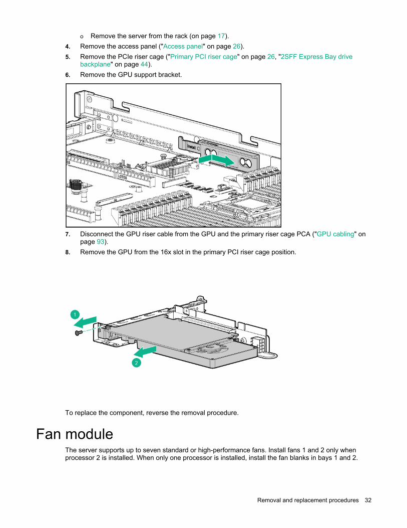
backplane" on page 44). 6. Remove the GPU support bracket.
7. Disconnect the GPU riser cable from the GPU and the primary riser cage PCA ("GPU cabling" on
page 93). 8. Remove the GPU from the 16x slot in the primary PCI riser cage position.
To replace the component, reverse the removal procedure.
Fan module The server supports up to seven standard or high-performance fans. Install fans 1 and 2 only when processor 2 is installed. When only one processor is installed, install the fan blanks in bays 1 and 2.

Removal and replacement procedures 33
To remove the component: 1. Extend the server from the rack (on page 17). 2. Remove the access panel ("Access panel" on page 26).
IMPORTANT: When a hot-plug fan is removed, the other fans in the server will increase speed to compensate.
CAUTION: To avoid server shutdown, a fan must be replaced within 60 seconds of being removed.
3. Remove the fan module.
To replace the component, reverse the removal procedure.
Fan blank Install fans 1 and 2 only when processor 2 is installed. When only one processor is installed, install the fan blanks in bays 1 and 2.
To remove the component: 1. Extend the server from the rack (on page 17). 2. Remove the access panel ("Access panel" on page 26).
Removal and replacement procedures 34
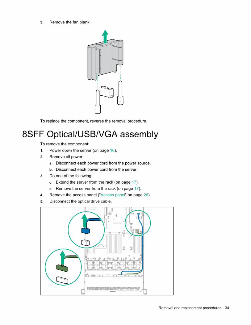
3. Remove the fan blank.
To replace the component, reverse the removal procedure.
8SFF Optical/USB/VGA assembly To remove the component: 1. Power down the server (on page 16). 2. Remove all power:
a. Disconnect each power cord from the power source. b. Disconnect each power cord from the server.
3. Do one of the following: o Extend the server from the rack (on page 17). o Remove the server from the rack (on page 17).
4. Remove the access panel ("Access panel" on page 26). 5. Disconnect the optical drive cable.

Removal and replacement procedures 35
6. Remove the optical drive.
To replace the component, reverse the removal procedure.
4LFF Optical/USB/VGA assembly To remove the component: 1. Power down the server (on page 16). 2. Remove all power:
a. Disconnect each power cord from the power source. b. Disconnect each power cord from the server.
3. Do one of the following: o Extend the server from the rack (on page 17). o Remove the server from the rack (on page 17).
4. Remove the access panel ("Access panel" on page 26). 5. Disconnect the cables:

Removal and replacement procedures 36
o Optical drive cabling
o USB/VGA cabling
6. Remove the assembly:

Removal and replacement procedures 37
o Optical drive assembly
o USB/VGA assembly
To replace the component, reverse the removal procedure.
8SFF Systems Insight Display To remove the component: 1. Power down the server (on page 16). 2. Remove all power:
a. Disconnect each power cord from the power source. b. Disconnect each power cord from the server.
3. Do one of the following: o Extend the server from the rack (on page 17). o Remove the server from the rack (on page 17).
4. Remove the access panel ("Access panel" on page 26).

Removal and replacement procedures 38
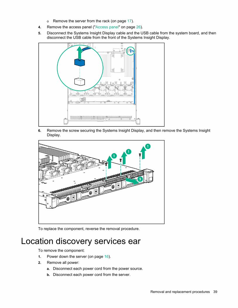
5. Disconnect the Systems Insight Display cable and the USB cable from the system board, and then disconnect the USB cable from the front of the Systems Insight Display.
6. Remove the screw securing the Systems Insight Display, and then remove the Systems Insight
Display.
To replace the component, reverse the removal procedure.
4LFF Systems Insight Display To remove the component: 1. Power down the server (on page 16). 2. Remove all power:
a. Disconnect each power cord from the power source. b. Disconnect each power cord from the server.
3. Do one of the following: o Extend the server from the rack (on page 17).
Removal and replacement procedures 39
o Remove the server from the rack (on page 17). 4. Remove the access panel ("Access panel" on page 26). 5. Disconnect the Systems Insight Display cable and the USB cable from the system board, and then
disconnect the USB cable from the front of the Systems Insight Display.
6. Remove the screw securing the Systems Insight Display, and then remove the Systems Insight
Display.
To replace the component, reverse the removal procedure.
Location discovery services ear To remove the component: 1. Power down the server (on page 16). 2. Remove all power:
a. Disconnect each power cord from the power source. b. Disconnect each power cord from the server.

Removal and replacement procedures 40
3. Do one of the following: o Extend the server from the rack (on page 17). o Remove the server from the rack (on page 17).
4. Remove the access panel ("Access panel" on page 26). 5. Remove the hot-plug fan or fan blank from fan bay 1 ("Fan module" on page 32). 6. Disconnect the discovery services cable.
7. Remove the discovery cable cover.
Removal and replacement procedures 41
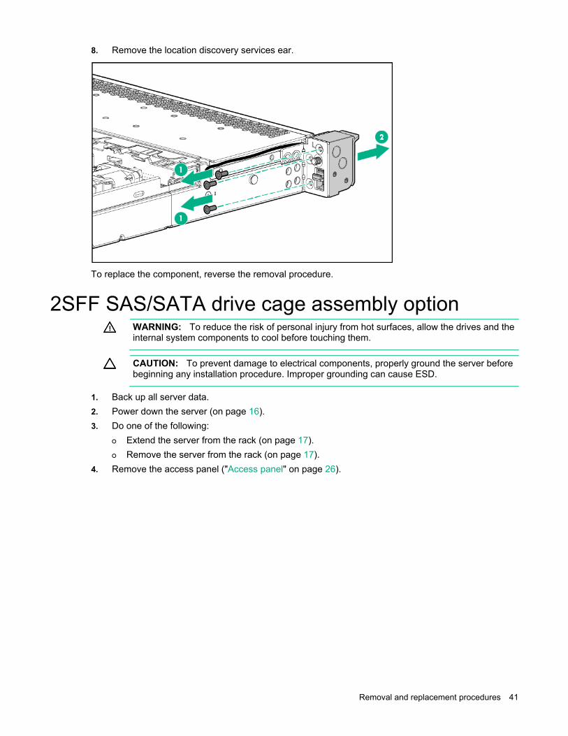
8. Remove the location discovery services ear.
To replace the component, reverse the removal procedure.
2SFF SAS/SATA drive cage assembly option
WARNING: To reduce the risk of personal injury from hot surfaces, allow the drives and the internal system components to cool before touching them.
CAUTION: To prevent damage to electrical components, properly ground the server before beginning any installation procedure. Improper grounding can cause ESD.
1. Back up all server data. 2. Power down the server (on page 16). 3. Do one of the following:
o Extend the server from the rack (on page 17). o Remove the server from the rack (on page 17).
4. Remove the access panel ("Access panel" on page 26).
Removal and replacement procedures 42
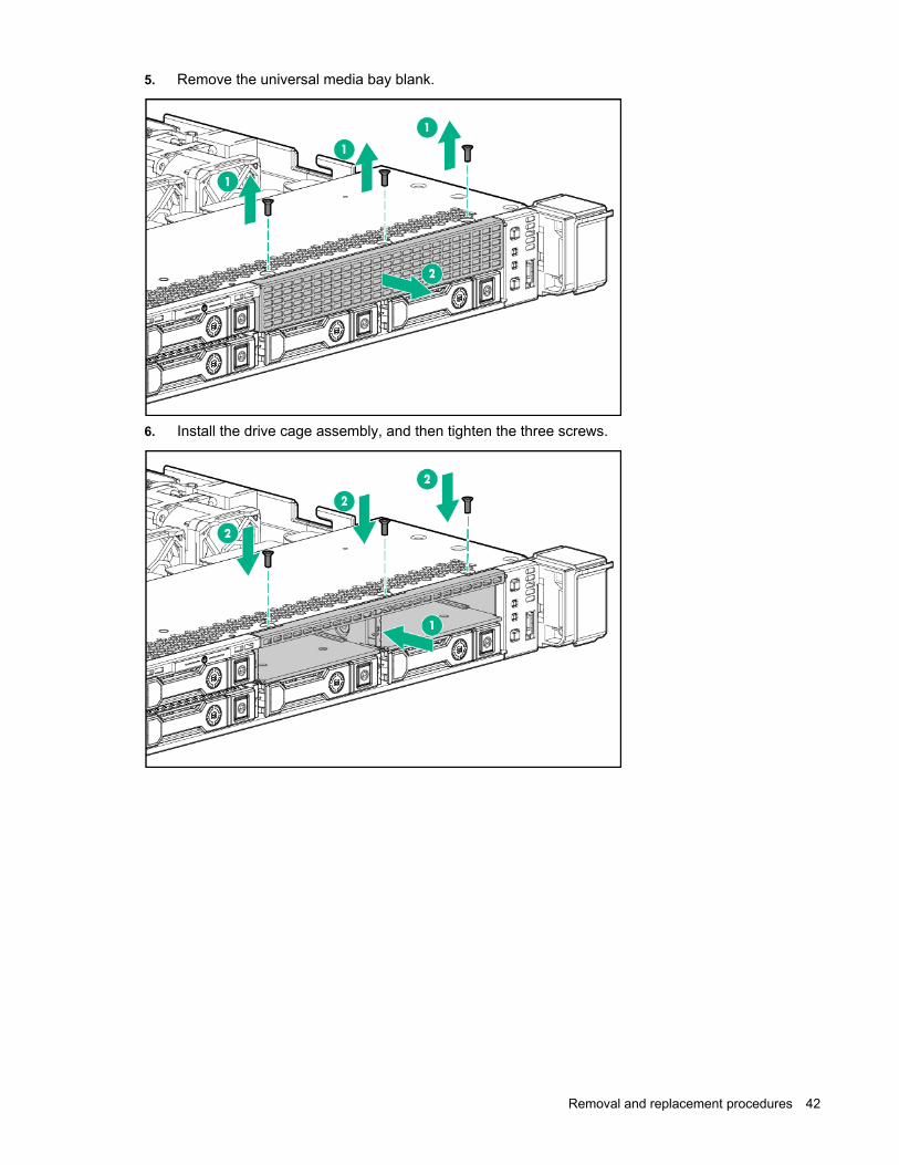
5. Remove the universal media bay blank.
6. Install the drive cage assembly, and then tighten the three screws.
Removal and replacement procedures 43
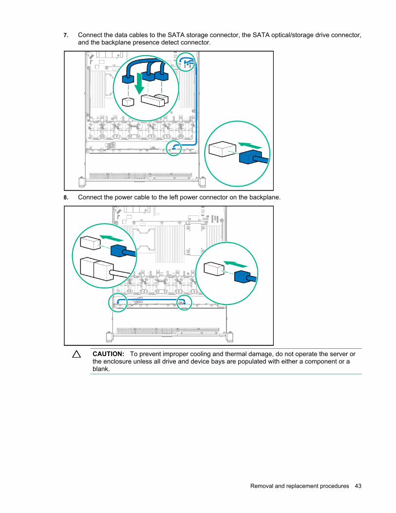
7. Connect the data cables to the SATA storage connector, the SATA optical/storage drive connector, and the backplane presence detect connector.
8. Connect the power cable to the left power connector on the backplane.
CAUTION: To prevent improper cooling and thermal damage, do not operate the server or the enclosure unless all drive and device bays are populated with either a component or a blank.

Removal and replacement procedures 44
9. Install drives or blanks in the empty drive bays.
2SFF Express Bay drive backplane
CAUTION: To prevent damage to electrical components, take the appropriate anti-static precautions before beginning any system installation. Improper grounding can cause electrostatic discharge.
To remove the component: 1. Back up all server data. 2. Remove all power:
a. Disconnect each power cord from the power source. b. Disconnect each power cord from the server.
3. Do one of the following: o Extend the server from the rack (on page 17). o Remove the server from the rack (on page 17).
4. Remove the access panel ("Access panel" on page 26). 5. Remove all drives and drive blanks.

Removal and replacement procedures 45
6. Disconnect the power cable from the left power connector on the backplane.
7. Disconnect the data cables on the Express bay drive cage from port 3 on the Express bay bridge
card.
8. Remove the primary PCI riser cage ("Primary PCI riser cage" on page 26, "2SFF Express Bay drive
backplane" on page 44).

Removal and replacement procedures 46
9. Remove the Express bay bridge card from slot 1.
10. Loosen the three screws, then remove the drive cage assembly.
To replace the component, reverse the removal procedure.
4LFF hard drive backplane To remove the component: 1. Power down the server (on page 16). 2. Remove all power:
a. Disconnect each power cord from the power source. b. Disconnect each power cord from the server.
3. Do one of the following: o Extend the server from the rack (on page 17). o Remove the server from the rack (on page 17).
4. Remove the access panel ("Access panel" on page 26).

Removal and replacement procedures 47
5. Remove all hot-plug hard drives ("Hot-plug SAS/SATA drives and SSDs" on page 22). 6. Disconnect all cables from the hard drive backplane. 7. Remove the hard drive backplane.
To replace the component, reverse the removal procedure.
8SFF hard drive backplane To remove the component: 1. Power down the server (on page 16). 2. Remove all power:
a. Disconnect each power cord from the power source. b. Disconnect each power cord from the server.
3. Do one of the following: o Extend the server from the rack (on page 17). o Remove the server from the rack (on page 17).
4. Remove the access panel ("Access panel" on page 26). 5. Remove all hot-plug hard drives ("Hot-plug SAS/SATA drives and SSDs" on page 22). 6. Disconnect all cables from the hard drive backplane.

Removal and replacement procedures 48
7. Remove the hard drive backplane.
To replace the component, reverse the removal procedure.
10SFF (6 NVMe + 4 SAS/SATA) Express Bay drive backplane
CAUTION: To prevent damage to electrical components, take the appropriate anti-static precautions before beginning any system installation. Improper grounding can cause electrostatic discharge.
To remove the component: 1. Back up all server data. 2. Remove all power:
a. Disconnect each power cord from the power source. b. Disconnect each power cord from the server.
3. Do one of the following: o Extend the server from the rack (on page 17). o Remove the server from the rack (on page 17).
4. Remove the access panel ("Access panel" on page 26). 5. Remove all drives and drive blanks. 6. Disconnect all power and data cables from the drive backplane. 7. Remove the primary PCIe riser cage ("Primary PCI riser cage" on page 26, "2SFF Express Bay drive
backplane" on page 44).

Removal and replacement procedures 49
8. Remove the Express bay bridge card from slot 1.
9. Remove the 8SFF Express Bay drive backplane.
10. Remove the 2SFF Express Bay drive backplane ("2SFF Express Bay drive backplane" on page 44).
To replace the component, reverse the removal procedure.
FlexibleLOM To remove the component: 1. Power down the server (on page 16). 2. Remove all power:
a. Disconnect each power cord from the power source. b. Disconnect each power cord from the server.
3. Disconnect the LAN segment cables. 4. Do one of the following:
o Extend the server from the rack (on page 17).

Removal and replacement procedures 50
o Remove the server from the rack (on page 17). 5. Remove the FlexibleLOM.
To replace the component, reverse the removal procedure.
Smart Storage Battery To remove the component: 1. Power down the server (on page 16). 2. Remove all power:
a. Disconnect each power cord from the power source. b. Disconnect each power cord from the server.
3. Do one of the following: o Extend the server from the rack (on page 17). o Remove the server from the rack (on page 17).
4. Remove the access panel ("Access panel" on page 26).

Removal and replacement procedures 51
5. Disconnect the Smart Storage Battery cable.
6. Remove the Smart Storage Battery.
To replace the component, reverse the removal procedure.
Expansion boards Expansion boards supported with this server include any board installed in the PCIe riser board assembly, controllers, and the Express Bay bridge card.
To remove the component: 1. Power down the server (on page 16). 2. Remove all power:
a. Disconnect each power cord from the power source. b. Disconnect each power cord from the server.
3. Do one of the following: o Extend the server from the rack (on page 17).

Removal and replacement procedures 52
o Remove the server from the rack (on page 17). 4. Remove the access panel ("Access panel" on page 26). 5. Remove the PCIe riser cage ("Primary PCI riser cage" on page 26). 6. Remove the expansion board.
To replace the component, reverse the removal procedure.
If you are not replacing the expansion board, install the screw back into the PCIe riser cage before installing the PCIe riser cage back into the server.
M.2 SSD enablement board To remove the component: 1. Power down the server (on page 16). 2. Remove all power:
a. Disconnect each power cord from the power source. b. Disconnect each power cord from the server.
3. Do one of the following: o Extend the server from the rack (on page 17). o Remove the server from the rack (on page 17).
4. Remove the access panel ("Access panel" on page 26). 5. Remove the PCIe riser cage ("Primary PCI riser cage" on page 26). 6. Disconnect the M.2 SSD cables from the M.2 enablement boards. For more information, see "M.2
SSD Enablement Board option cabling (on page 92)."

Removal and replacement procedures 53
7. Remove the M.2 SSD enablement board.
To replace the component, reverse the removal procedure.
If you are not replacing the enablement board, install the screw and the PCIe blank into the PCIe riser cage before installing the PCIe riser cage back into the server.
DIMMs To remove the component: 1. Power down the server (on page 16). 2. Remove all power:
a. Disconnect each power cord from the power source. b. Disconnect each power cord from the server.
3. Do one of the following: o Extend the server from the rack (on page 17). o Remove the server from the rack (on page 17).
4. Remove the access panel ("Access panel" on page 26).

Removal and replacement procedures 54
5. Remove the DIMM.
To replace the component, reverse the removal procedure.
Heatsink
WARNING: To reduce the risk of personal injury from hot surfaces, allow the drives and the internal system components to cool before touching them.
CAUTION: The heatsink thermal interface media is not reusable and must be replaced if the heatsink is removed from the processor after it has been installed.
CAUTION: To avoid thermal shutdown, all fans must be installed in a dual processor configuration.
To remove the component: 1. Power down the server (on page 16). 2. Remove all power:
a. Disconnect each power cord from the power source. b. Disconnect each power cord from the server.
3. Do one of the following: o Extend the server from the rack (on page 17). o Remove the server from the rack (on page 17).
4. Remove the access panel ("Access panel" on page 26).

Removal and replacement procedures 55
5. Remove the heatsink.
To replace the component, reverse the removal procedure.
High-performance heatsink
WARNING: To reduce the risk of personal injury from hot surfaces, allow the drives and the internal system components to cool before touching them.
CAUTION: The heatsink thermal interface media is not reusable and must be replaced if the heatsink is removed from the processor after it has been installed.
CAUTION: To avoid thermal shutdown, all fans must be installed in a dual processor configuration.
To remove the component: 1. Power down the server (on page 16). 2. Remove all power:
a. Disconnect each power cord from the power source. b. Disconnect each power cord from the server.
3. Do one of the following: o Extend the server from the rack (on page 17). o Remove the server from the rack (on page 17).
4. Remove the access panel ("Access panel" on page 26).

Removal and replacement procedures 56
5. Remove the heatsink.
To replace the component, reverse the removal procedure.
Processor
WARNING: To reduce the risk of personal injury from hot surfaces, allow the drives and the internal system components to cool before touching them.
CAUTION: To prevent possible server malfunction, do not mix processors of different speeds or cache sizes. Refer to the label on the processor heatsink for a description of the processor.
CAUTION: To prevent possible server overheating, always populate each processor socket with a processor socket cover and a heatsink blank or a processor and a heatsink.
IMPORTANT: Processor socket 1 must always be populated. If processor socket 1 is empty, the server does not power up.
Depending on the memory configuration and processor model, the memory speed may run at 1600MHz, 1866MHz, or 2133MHz.
To remove the component: 1. Update the system ROM.
Locate and download the latest ROM version from the Hewlett Packard Enterprise website (http://www.hpe.com/support). Follow the instructions on the website to update the system ROM.
2. Power down the server (on page 16). 3. Do one of the following:
o Extend the server from the rack (on page 17). o Remove the server from the rack (on page 17).
4. Remove the access panel ("Access panel" on page 26). 5. Remove the heatsink ("Heatsink" on page 54).

Removal and replacement procedures 57
6. Open each of the processor locking levers in the order indicated, and then open the processor retaining bracket.
7. Remove the processor from the processor retaining bracket.
CAUTION: To avoid damage to the processor, do not touch the bottom of the processor, especially the contact area.
To replace the component:
CAUTION: To avoid damage to the system board, processor socket, and screws, do not overtighten the heatsink screws.

Removal and replacement procedures 58
1. Install the processor. Verify that the processor is fully seated in the processor retaining bracket by visually inspecting the processor installation guides on either side of the processor. THE PINS ON THE SYSTEM BOARD ARE VERY FRAGILE AND EASILY DAMAGED.
CAUTION: THE PINS ON THE SYSTEM BOARD ARE VERY FRAGILE AND EASILY DAMAGED. To avoid damage to the system board, do not touch the processor or the processor socket contacts.
2. Close the processor retaining bracket. When the processor is installed properly inside the processor retaining bracket, the processor retaining bracket clears the flange on the front of the socket.
CAUTION: Do not press down on the processor. Pressing down on the processor may cause damage to the processor socket and the system board. Press only in the area indicated on the processor retaining bracket.

Removal and replacement procedures 59
3. Press and hold the processor retaining bracket in place, and then close each processor locking lever. Press only in the area indicated on the processor retaining bracket.
4. Align and install the heatsink.
5. Install the access panel.
System battery If the server no longer automatically displays the correct date and time, you may need to replace the battery that provides power to the real-time clock.
WARNING: The computer contains an internal lithium manganese dioxide, a vanadium pentoxide, or an alkaline battery pack. A risk of fire and burns exists if the battery pack is not properly handled. To reduce the risk of personal injury: • Do not attempt to recharge the battery. • Do not expose the battery to temperatures higher than 60°C (140°F). • Do not disassemble, crush, puncture, short external contacts, or dispose of in fire or water. • Replace only with the spare designated for this product.

Removal and replacement procedures 60
To remove the component: 1. Power down the server (on page 16). 2. Remove all power:
a. Disconnect each power cord from the power source. b. Disconnect each power cord from the server.
3. Do one of the following: o Extend the server from the rack (on page 17). o Remove the server from the rack (on page 17).
4. Remove the access panel ("Access panel" on page 26). 5. Locate the battery ("System board components" on page 79). 6. Remove the battery.
To replace the component, reverse the removal procedure.
For more information about battery replacement or proper disposal, contact an authorized reseller or an authorized service provider.
System board To remove the component: 1. Power down the server (on page 16). 2. Remove all power:
a. Disconnect each power cord from the power source. b. Disconnect each power cord from the server.
3. Do one of the following: o Extend the server from the rack (on page 17). o Remove the server from the rack (on page 17).
4. Remove all power supplies ("AC power supply" on page 24). 5. Remove the access panel ("Access panel" on page 26). 6. Remove the PCIe riser cage ("Primary PCI riser cage" on page 26). 7. If installed, remove the secondary PCIe riser cage ("Secondary PCI riser cage" on page 28). 8. Remove the fan module.
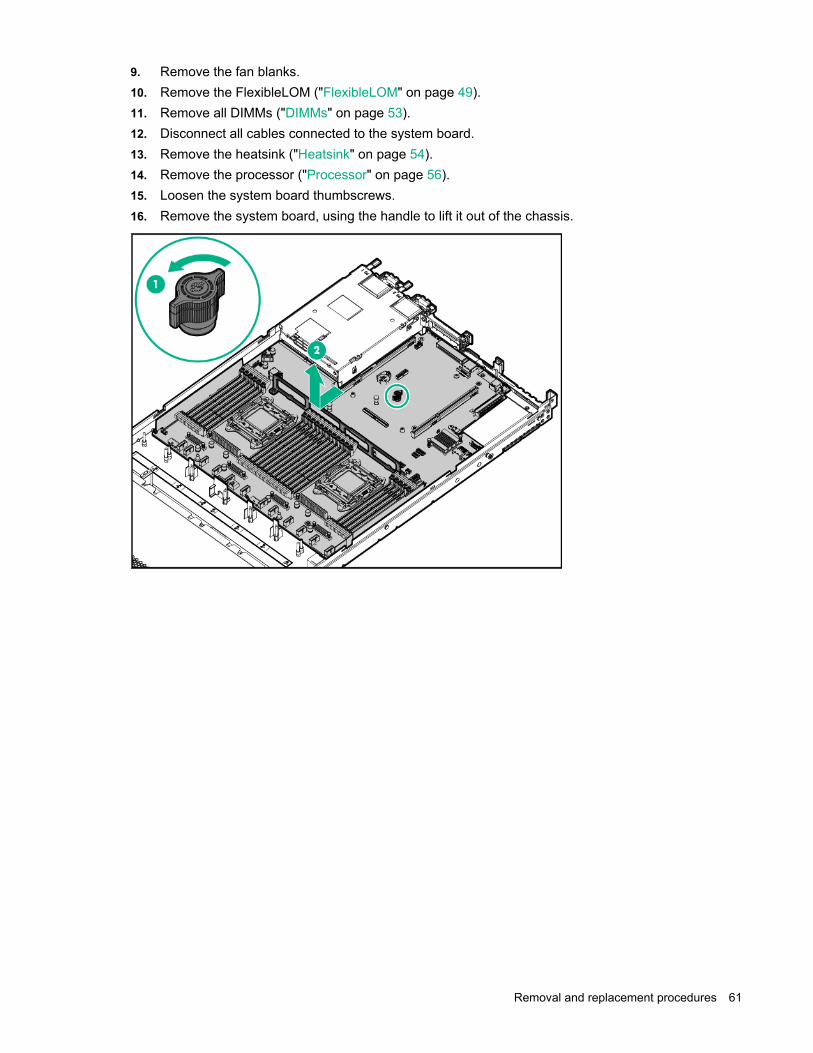
Removal and replacement procedures 61
9. Remove the fan blanks. 10. Remove the FlexibleLOM ("FlexibleLOM" on page 49). 11. Remove all DIMMs ("DIMMs" on page 53). 12. Disconnect all cables connected to the system board. 13. Remove the heatsink ("Heatsink" on page 54). 14. Remove the processor ("Processor" on page 56). 15. Loosen the system board thumbscrews. 16. Remove the system board, using the handle to lift it out of the chassis.

Removal and replacement procedures 62
To replace the component: 1. Install the spare system board.
2. Open each of the processor locking levers in the order indicated, and then open the processor
retaining bracket.

Removal and replacement procedures 63
3. Remove the clear processor socket cover. Retain the processor socket cover for future use.
4. Install the processor. Verify that the processor is fully seated in the processor retaining bracket by
visually inspecting the processor installation guides on either side of the processor. THE PINS ON THE SYSTEM BOARD ARE VERY FRAGILE AND EASILY DAMAGED.
CAUTION: Do not press down on the processor. Pressing down on the processor may cause damage to the processor socket and the system board. Press only in the area indicated on the processor retaining bracket.
CAUTION: Close and hold down the processor cover socket while closing the processor locking levers. The levers should close without resistance. Forcing the levers closed can damage the processor and socket, requiring system board replacement.
5. Close the processor retaining bracket. When the processor is installed properly inside the processor retaining bracket, the processor retaining bracket clears the flange on the front of the socket.

Removal and replacement procedures 64
6. Press and hold the processor retaining bracket in place, and then close each processor locking lever. Press only in the area indicated on the processor retaining bracket.
7. Install the processor socket cover on the failed system board. 8. Clean the old thermal grease from the heatsink and the top of the processor with the alcohol swab.
Allow the alcohol to evaporate before continuing. 9. Apply all the grease to the top of the processor in the following pattern to ensure even distribution.

Removal and replacement procedures 65
10. Install the heatsink.
IMPORTANT: Install all components with the same configuration that was used on the failed system board.
11. Install all components removed from the failed system board. 12. Install the access panel. 13. Install the power supplies ("AC power supply" on page 24). 14. Power up the server.
After you replace the system board, you must re-enter the server serial number and the product ID. 1. During the server startup sequence, press the F9 key to access UEFI System Utilities. 2. Select the System Configuration > BIOS/Platform Configuration (RBSU) > Advanced Options
> Advanced System ROM Options > Serial Number, and then press the Enter key. 3. Enter the serial number and press the Enter key. The following message appears:
The serial number should only be modified by qualified service personnel. This value should always match the serial number located on the chassis.
4. Press the Enter key to clear the warning. 5. Enter the serial number and press the Enter key. 6. Select Product ID. The following warning appears:
Warning: The Product ID should ONLY be modified by qualified service personnel. This value should always match the Product ID located on the chassis.
7. Enter the product ID and press the Enter key. 8. Press the F10 key to confirm exiting System Utilities. The server automatically reboots.
HP Trusted Platform Module The TPM is not a customer-removable part.
CAUTION: Any attempt to remove an installed TPM from the system board breaks or disfigures the TPM security rivet. Upon locating a broken or disfigured rivet on an installed TPM, administrators should consider the system compromised and take appropriate measures to ensure the integrity of the system data.

Removal and replacement procedures 66
If you suspect a TPM board failure, leave the TPM installed and remove the system board. Contact a Hewlett Packard Enterprise authorized service provider for a replacement system board and TPM board.

Troubleshooting 67
Troubleshooting
Troubleshooting resources The HPE ProLiant Gen9 Troubleshooting Guide, Volume I: Troubleshooting provides procedures for resolving common problems and comprehensive courses of action for fault isolation and identification, issue resolution, and software maintenance on ProLiant servers and server blades. To view the guide, select a language:
• English (http://www.hpe.com/support/Gen9_TSG_en)
• French (http://www.hpe.com/support/Gen9_TSG_fr)
• Spanish (http://www.hpe.com/support/Gen9_TSG_es)
• German (http://www.hpe.com/support/Gen9_TSG_de)
• Japanese (http://www.hpe.com/support/Gen9_TSG_ja)
• Simplified Chinese (http://www.hpe.com/support/Gen9_TSG_zh_cn)
The HPE ProLiant Gen9 Troubleshooting Guide, Volume II: Error Messages provides a list of error messages and information to assist with interpreting and resolving error messages on ProLiant servers and server blades. To view the guide, select a language:
• English (http://www.hpe.com/support/Gen9_EMG_en)
• French (http://www.hpe.com/support/Gen9_EMG_fr)
• Spanish (http://www.hpe.com/support/Gen9_EMG_es)
• German (http://www.hpe.com/support/Gen9_EMG_de)
• Japanese (http://www.hpe.com/support/Gen9_EMG_ja)
• Simplified Chinese (http://www.hpe.com/support/Gen9_EMG_zh_cn)

Diagnostic tools 68
Diagnostic tools
Product QuickSpecs For more information about product features, specifications, options, configurations, and compatibility, see the product QuickSpecs on the Hewlett Packard Enterprise website (http://www.hpe.com/info/qs).
Active Health System The HPE Active Health System provides the following features:
• Combined diagnostics tools/scanners
• Always on, continuous monitoring for increased stability and shorter downtimes
• Rich configuration history
• Health and service alerts
• Easy export and upload to Service and Support
The Active Health System monitors and records changes in the server hardware and system configuration. The Active Health System assists in diagnosing problems and delivering rapid resolution if server failures occur.
The Active Health System collects the following types of data:
• Server model
• Serial number
• Processor model and speed
• Storage capacity and speed
• Memory capacity and speed
• Firmware/BIOS
Active Health System does not collect information about Active Health System users' operations, finances, customers, employees, partners, or data center, such as IP addresses, host names, user names, and passwords. Active Health System does not parse or change operating system data from third-party error event log activities, such as content created or passed through by the operating system.
The data that is collected is managed according to the Hewlett Packard Enterprise Data Privacy policy. For more information see the Hewlett Packard Enterprise website (http://www.hpe.com/info/privacy).
The Active Health System, in conjunction with the system monitoring provided by Agentless Management or SNMP Pass-thru, provides continuous monitoring of hardware and configuration changes, system status, and service alerts for various server components.
The Agentless Management Service is available in the SPP, which can be downloaded from the Hewlett Packard Enterprise website (http://www.hpe.com/servers/spp/download). The Active Health System log can be downloaded manually from iLO 4 or HPE Intelligent Provisioning and sent to Hewlett Packard Enterprise.
For more information, see the following documents:
• iLO User Guide on the Hewlett Packard Enterprise website (http://www.hpe.com/info/ilo/docs)

Diagnostic tools 69
• Intelligent Provisioning User Guide on the Hewlett Packard Enterprise website (http://www.hpe.com/info/intelligentprovisioning/docs)
HPE iLO The iLO 4 subsystem is a standard component of ProLiant servers that simplifies initial server setup, server health monitoring, power and thermal optimization, and remote server administration. The iLO 4 subsystem includes an intelligent microprocessor, secure memory, and a dedicated network interface. This design makes iLO 4 independent of the host server and its operating system.
iLO 4 enables and manages the Active Health System (on page 68) and also features Agentless Management. All key internal subsystems are monitored by iLO 4. If enabled, SNMP alerts are sent directly by iLO 4 regardless of the host operating system or even if no host operating system is installed.
Using iLO 4, you can do the following:
• Access a high-performance and secure Integrated Remote Console to the server from anywhere in the world if you have a network connection to the server.
• Use the shared .NET Integrated Remote Console to collaborate with up to four server administrators.
• Remotely mount high-performance Virtual Media devices to the server.
• Securely and remotely control the power state of the managed server.
• Implement true Agentless Management with SNMP alerts from iLO, regardless of the state of the host server.
• Download the Active Health System log.
• Register for HPE remote support.
• Use iLO Federation to manage multiple servers from one system running the iLO web interface.
• Use Virtual Power and Virtual Media from the GUI, the CLI, or the iLO scripting toolkit for many tasks, including the automation of deployment and provisioning.
• Control iLO 4 by using a remote management tool.
For more information about iLO 4 features, see the iLO 4 documentation on the Hewlett Packard Enterprise website (http://www.hpe.com/info/ilo/docs).
The iLO 4 hardware and firmware features and functionality, such as NAND size and embedded user partition, vary depending on the server model. For a complete list of supported features and functionality, see the iLO 4 QuickSpecs on the Hewlett Packard Enterprise website (http://www.hpe.com/info/Quickspecs-iLO).
HPE ProLiant Pre-boot Health Summary If the server will not start up, you can use iLO to display diagnostic information on an external monitor. This feature is supported on servers that support external video and have a UID button or an SUV connector. When power is available to the server but the server is not powered on, iLO runs on auxiliary power and can take control of the server video adapter to display the HPE ProLiant Pre-boot Health Summary.
For additional information, see the following documents:
• iLO 4 User Guide — See the Hewlett Packard Enterprise website (http://www.hpe.com/info/ilo/docs).
• ProLiant Gen9 Troubleshooting Guide, Volume I: Troubleshooting — See "Troubleshooting Resources (on page 67)."

Diagnostic tools 70
Integrated Management Log The IML records hundreds of events and stores them in an easy-to-view form. The IML timestamps each event with 1-minute granularity.
You can view recorded events in the IML in several ways, including the following:
• From within HPE SIM
• From within UEFI System Utilities
• From within the Embedded UEFI shell
• From within operating system-specific IML viewers: o For Windows: IML Viewer o For Linux: IML Viewer Application
• From within the iLO web interface
• From within Insight Diagnostics
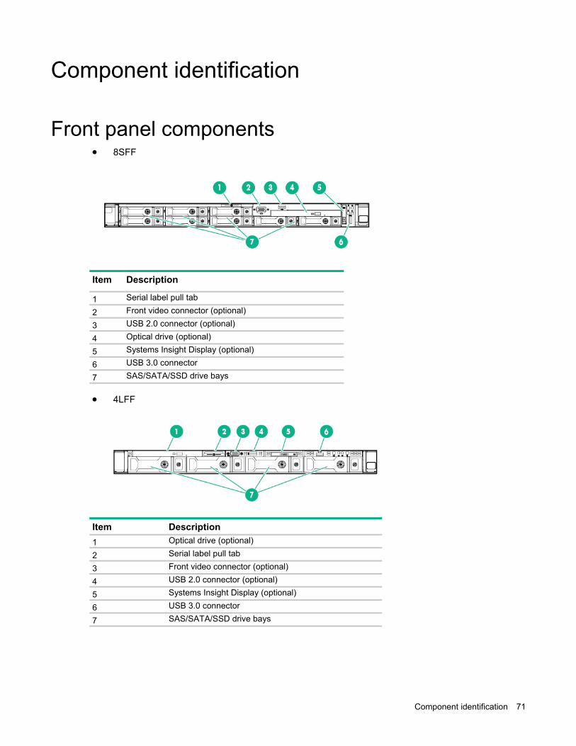
Component identification 71
Component identification
Front panel components • 8SFF
Item Description
1 Serial label pull tab
2 Front video connector (optional)
3 USB 2.0 connector (optional)
4 Optical drive (optional)
5 Systems Insight Display (optional)
6 USB 3.0 connector
7 SAS/SATA/SSD drive bays
• 4LFF
Item Description 1 Optical drive (optional)
2 Serial label pull tab
3 Front video connector (optional)
4 USB 2.0 connector (optional)
5 Systems Insight Display (optional)
6 USB 3.0 connector
7 SAS/SATA/SSD drive bays

Component identification 72
Front panel LEDs and buttons • 8SFF
Item Description Status 1 Power On/Standby button
and system power LED* Solid green = System on Flashing green (1 Hz/cycle per sec) = Performing power on sequence Solid amber = System in standby Off = No power present**
2 Health LED* Solid green = Normal Flashing green (1 Hz/cycle per sec) = iLO is rebooting. Flashing amber = System degraded Flashing red (1 Hz/cycle per sec) = System critical†
3 NIC status LED* Solid green = Link to network Flashing green (1 Hz/cycle per sec) = Network active Off = No network activity
4 UID button/LED* Solid blue = Activated Flashing blue: • 1 Hz/cycle per sec = Remote management or firmware upgrade
in progress • 4 Hz/cycle per sec = iLO manual reboot sequence initiated • 8 Hz/cycle per sec = iLO manual reboot sequence in progress Off = Deactivated
*When all four LEDs described in this table flash simultaneously, a power fault has occurred. For more information, see "Power fault LEDs (on page 74)." **Facility power is not present, power cord is not attached, no power supplies are installed, power supply failure has occurred, or the power button cable is disconnected. †If the health LED indicates a degraded or critical state, review the system IML or use iLO to review the system health status.

Component identification 73
• 4LFF
Item Description Status 1 UID button/LED* Solid blue = Activated
Flashing blue: • 1 Hz/cycle per sec = Remote management or firmware upgrade
in progress • 4 Hz/cycle per sec = iLO manual reboot sequence initiated • 8 Hz/cycle per sec = iLO manual reboot sequence in progress Off = Deactivated
2 NIC status LED* Solid green = Link to network Flashing green (1 Hz/cycle per sec) = Network active Off = No network activity
3 Health LED* Solid green = Normal Flashing green (1 Hz/cycle per sec) = iLO is rebooting. Flashing amber = System degraded Flashing red (1 Hz/cycle per sec) = System critical†
4 Power On/Standby button and system power LED*
Solid green = System on Flashing green (1 Hz/cycle per sec) = Performing power on sequence Solid amber = System in standby Off = No power present**
*When all four LEDs described in this table flash simultaneously, a power fault has occurred. For more information, see "Power fault LEDs (on page 74)." **Facility power is not present, power cord is not attached, no power supplies are installed, power supply failure has occurred, or the power button cable is disconnected. †To identify components in a degraded or critical state, see the Systems Insight Display LEDs, check iLO/BIOS logs, and reference the server troubleshooting guide.
UID button functionality The UID button can be used to display the HPE ProLiant Pre-boot Health Summary when the server will not power on. For more information, see the HPE iLO 4 User Guide on the Hewlett Packard Enterprise website (http://www.hpe.com/info/ilo/docs).
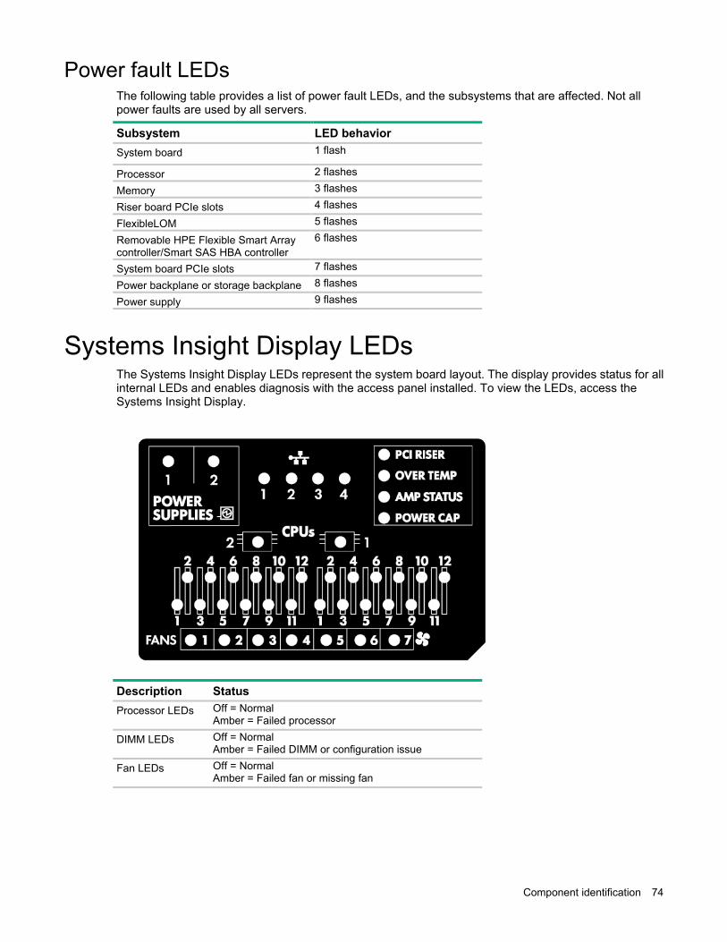
Component identification 74
Power fault LEDs The following table provides a list of power fault LEDs, and the subsystems that are affected. Not all power faults are used by all servers.
Subsystem LED behavior System board 1 flash
Processor 2 flashes
Memory 3 flashes
Riser board PCIe slots 4 flashes
FlexibleLOM 5 flashes
Removable HPE Flexible Smart Array controller/Smart SAS HBA controller
6 flashes
System board PCIe slots 7 flashes
Power backplane or storage backplane 8 flashes
Power supply 9 flashes
Systems Insight Display LEDs The Systems Insight Display LEDs represent the system board layout. The display provides status for all internal LEDs and enables diagnosis with the access panel installed. To view the LEDs, access the Systems Insight Display.
Description Status Processor LEDs Off = Normal
Amber = Failed processor
DIMM LEDs Off = Normal Amber = Failed DIMM or configuration issue
Fan LEDs Off = Normal Amber = Failed fan or missing fan

Component identification 75
Description Status NIC LEDs Off = No link to network
Solid green = Network link Flashing green = Network link with activity If power is off, the front panel LED is not active. For status, see "Rear panel LEDS and buttons (on page 77)."
Power supply LEDs
Off = Normal Solid amber = Power subsystem degraded, power supply failure, or input power lost.
PCI riser LED Off = Normal Amber = Incorrectly installed PCI riser cage
Over temp LED Off = Normal Amber = High system temperature detected
Amp Status LED Off = AMP modes disabled Solid green = AMP mode enabled Solid amber = Failover Flashing amber = Invalid configuration
Power cap LED Off = System is in standby, or no cap is set. Solid green = Power cap applied
For more information, see "Systems Insight Display LED combinations (on page 75)."
Systems Insight Display LED combinations When the health LED on the front panel illuminates either amber or red, the server is experiencing a health event. Combinations of illuminated Systems Insight Display LEDs, the system power LED, and the health LED indicate system status.
Systems Insight Display LED and color
Health LED System power LED
Status
Processor (amber) Red Amber One or more of the following conditions may exist: • Processor in socket X has failed. • Processor X is not installed in the
socket. • Processor X is unsupported. • ROM detects a failed processor during
POST.
Processor (amber) Amber Green Processor in socket X is in a pre-failure condition.
DIMM (amber) Red Green One or more DIMMs have failed.
DIMM (amber) Amber Green DIMM in slot X is in a pre-failure condition.
Over temp (amber) Amber Green The Health Driver has detected a cautionary temperature level.
Over temp (amber) Red Amber The server has detected a hardware critical temperature level.
PCI riser (amber) Red Green The PCI riser cage is not seated properly.
Fan (amber) Amber Green One fan has failed or has been removed.
Fan (amber) Red Green Two or more fans have failed or been removed.
Power supply (amber) Red Amber One or more of the following conditions may exist: • Only one power supply is installed and

Component identification 76
Systems Insight Display LED and color
Health LED System power LED
Status
that power supply is in standby. • Power supply fault • System board fault
Power supply (amber) Amber Green One or more of the following conditions may exist: • Redundant power supply is installed
and only one power supply is functional. • AC power cord is not plugged into
redundant power supply. • Redundant power supply fault • Power supply mismatch at POST or
power supply mismatch through hot-plug addition
Power cap (off) — Amber Standby
Power cap (green) — Flashing green Waiting for power
Power cap (green) — Green Power is available.
Power cap (flashing amber)
— Amber Power is not available.
IMPORTANT: If more than one DIMM slot LED is illuminated, further troubleshooting is required. Test each bank of DIMMs by removing all other DIMMs. Isolate the failed DIMM by replacing each DIMM in a bank with a known working DIMM.
Rear panel components
Item Description 1 Slot 1 PCIe3 x16 (16, 8, 4, 1)
2 Slot 2 PCIe 3 x8 ( 8, 4, 1)
3 Slot 3 PCIe 3 x16 ( 16, 8, 4, 1)*
4 Power supply 2
5 Power supply 1
6 Video connector
7 NIC connector 4
8 NIC connector 3
9 NIC connector 2
10 NIC connector 1

Component identification 77
Item Description 11 iLO 4 connector
12 Serial connector (optional)
13 USB 3.0 connectors
14 FlexibleLOM bay
*The slot 3 PCIe 3 riser is optional and requires a second processor before installation.
Rear panel LEDs and buttons
Item Description Status 1 UID LED Solid blue = Identification is activated.
Flashing blue = System is being managed remotely. Off = Identification is deactivated.
2L iLO 4/standard NIC activity LED
Solid green = Activity exists. Flashing green = Activity exists. Off = No activity exists.
2R iLO 4/standard NIC link LED
Solid green = Link exists. Off = No link exists.
3 Power supply 2 LED
Solid green = Normal Off = One or more of the following conditions exists: • AC power unavailable • Power supply failed • Power supply in standby mode • Power supply exceeded current limit
4 Power supply 1 LED
Solid green = Normal Off = One or more of the following conditions exists: • AC power unavailable
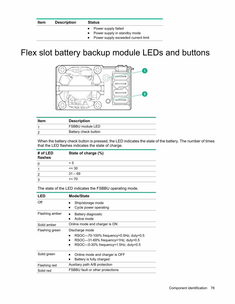
Component identification 78
Item Description Status • Power supply failed • Power supply in standby mode • Power supply exceeded current limit
Flex slot battery backup module LEDs and buttons
Item Description 1 FSBBU module LED
2 Battery check button
When the battery check button is pressed, the LED indicates the state of the battery. The number of times that the LED flashes indicates the state of charge.
# of LED flashes
State of charge (%)
0 < 5
1 <= 30
2 31 – 69
3 >= 70
The state of the LED indicates the FSBBU operating mode.
LED Mode/State Off • Ship/storage mode
• Cycle power operating
Flashing amber • Battery diagnostic • Active mode
Solid amber Online mode and charger is ON
Flashing green Discharge mode • RSOC—70-100% frequency=0.5Hz; duty=0.5 • RSOC—31-69% frequency=1Hz; duty=0.5 • RSOC—0-30% frequency=1.5Hz; duty=0.5
Solid green • Online mode and charger is OFF • Battery is fully charged
Flashing red Auxiliary path A/B protection
Solid red FSBBU fault or other protections

Component identification 79
For more information about the FSBBU module, see "750 W Flex Slot Hot Plug Battery Backup Module ("HPE 750W Flex Slot Hot Plug Battery Backup Module" on page 25)."
System board components
Item Description 1 FlexibleLOM connector
2 Primary (processor 1) PCI riser connector
3 NMI jumper
4 System maintenance switch
5 Front VGA/USB 2.0 connector
6 x4 SATA port 1
7 x4 SATA port 2
8 Backplane presence detect connector
9 Optical/SATA port 5
10 SATA port 4
11 Front power/USB 3.0 connector
12 HPE Smart Storage Battery connector
13 Optional Location Discovery Services connector
14 Drive backplane power connector
15 microSD card slot
16 Dual internal USB 3.0 connector
17 Smart Array/HBA connector
18 Secondary (processor 2) PCI riser connector
19 System battery
20 TPM connector
21 Optional serial port connector

Component identification 80
System maintenance switch
Position Default Function S1 Off Off = iLO 4 security is enabled.
On = iLO 4 security is disabled.
S2 Off Off = System configuration can be changed. On = System configuration is locked.
S3 Off Reserved
S4 Off Reserved
S5 Off Off = Power-on password is enabled. On = Power-on password is disabled.
S6 Off Off = No function On = ROM reads system configuration as invalid.
S7 Off Off = Set default boot mode to UEFI. On = Set default boot mode to legacy.
S8 — Reserved
S9 — Reserved
S10 — Reserved
S11 — Reserved
S12 — Reserved
*To access the redundant ROM, set S1, S5, and S6 to On. **When the system maintenance switch position 6 is set to the On position, the system is prepared to erase all system configuration settings from CMOS.
CAUTION: Clearing CMOS deletes configuration information. Be sure to properly configure the server or data loss could occur.
IMPORTANT: Before using the S7 switch to change to Legacy BIOS Boot Mode, be sure the HPE Dynamic Smart Array B140i Controller is disabled. Do not use the B140i controller when the server is in Legacy BIOS Boot Mode.
NMI jumper The NMI jumper allows administrators to perform a memory dump before performing a hard reset. Crash dump analysis is an essential part of eliminating reliability problems, such as hangs or crashes in OSs, device drivers, and applications. Many crashes can freeze a system, requiring you to do a hard reset. Resetting the system erases any information that would support root cause analysis.
Systems running Microsoft® Windows® experience a blue-screen trap when the OS crashes. When this happens, Microsoft® recommends that system administrators perform an NMI event by temporarily shorting the NMI header with a jumper. The NMI event enables a hung system to become responsive again.

Component identification 81
DIMM slots DIMM slots are numbered sequentially (1 through 12) for each processor. The supported AMP modes use the letter assignments for population guidelines.
Non-hot-plug PCI riser board slot definitions Primary riser cage connector, connected to processor 1 or the southbridge
PCIe 3-slot riser cage PCIe 2-slot x16 riser cage*
1 - 3/4L/FH PCIe3 x16 (16, 8,4,2,1) PCIe3 x16 (16,8,4,2,1)
2 - LP PCIe3 x8 (8,4,2,1) PCIe3* x8 (8,4,2,1)
3 - LP/3/4L/FH PCIe3 x16 (16, 8,4,2,1)** —
*The server ships with one PCIe3 riser cage installed in the primary riser cage connector.
**The x16 PCIe3 riser cage is optional and can be converted to a FH riser. This conversion requires a second processor to be installed.
Notes:
• "Primary" denotes the riser cage is installed in the primary riser connector.
• "Secondary" denotes the riser cage is installed in the secondary riser connector.
• Installing the riser cages listed in the table above in either the primary or secondary riser connectors determines the form factor of the PCI cards supported by those riser cages.

Component identification 82
• FL/FH denotes full-length, full-height. HL/FH denotes half-length, full-height. LP denotes low profile.
Device numbers • 4LFF configuration
• 8SFF configuration
• 10SFF configurations
With the 10SFF (6 NVMe + 4 SAS/SATA) Express Bay Enablement Option, the server supports SAS, SATA, and PCIe-based NVMe drives in the following locations: o Bays 1 through 4 support SFF SAS and SATA drives only

Component identification 83
o Bays 5 through 10 support SFF PCIe-based NVMe drives only
Hot-plug drive LED definitions
Item LED Status Definition 1 Locate Solid blue The drive is being identified by a host application.
Flashing blue The drive carrier firmware is being updated or requires an update.
2 Activity ring Rotating green Drive activity
Off No drive activity
3 Do not remove Solid white Do not remove the drive. Removing the drive causes one or more of the logical drives to fail.
Off Removing the drive does not cause a logical drive to fail.
4 Drive status Solid green The drive is a member of one or more logical drives.
Flashing green The drive is rebuilding or performing a RAID migration, strip size migration, capacity expansion, or logical drive extension, or is erasing.
Flashing amber/green
The drive is a member of one or more logical drives and predicts the drive will fail.
Flashing amber The drive is not configured and predicts the drive will fail.
Solid amber The drive has failed.
Off The drive is not configured by a RAID controller.
NVMe SSD components The NVMe SSD is a PCIe bus device. A device attached to a PCIe bus cannot be removed without allowing the device and bus to complete and cease the signal/traffic flow.
CAUTION: Do not remove an NVMe SSD from the drive bay while the Do Not Remove button LED is flashing. The Do Not Remove button LED flashes to indicate the device is still in use. Removal of the NVMe SSD before the device has completed and ceased signal/traffic flow can cause loss of data.

Component identification 84
Item Description 1 Release lever
2 Activity ring
3 Do Not Remove button
4 Power button
Hot-plug fans
CAUTION: To avoid damage to server components, fan blanks must be installed in fan bays 1 and 2 in a single-processor configuration.
The only two valid fan configurations are listed in the following table.
Configuration Fan bay 1 Fan bay 2 Fan bay 3 Fan bay 4 Fan bay 5 Fan bay 6 Fan bay 7 1 processor Fan blank Fan blank Fan Fan Fan Fan Fan
2 processors Fan Fan Fan Fan Fan Fan Fan
For a single-processor configuration, five fans and two blanks are required in specific fan bays for redundancy.

Component identification 85
For a dual-processor configuration, seven fans are required for redundancy. A fan failure or missing fan causes a loss of redundancy. A second fan failure or missing fan causes an orderly shutdown of the server.
The high performance fan option might be necessary for the following installations:
• LR DIMM configuration
• ASHRAE compliant configurations For more information, see the Hewlett Packard Enterprise website (http://www.hpe.com/servers/ASHRAE).
The server supports variable fan speeds. The fans operate at minimum speed until a temperature change requires a fan speed increase to cool the server. The server shuts down during the following temperature-related scenarios:
• At POST and in the OS, iLO 4 performs an orderly shutdown if a cautionary temperature level is detected. If the server hardware detects a critical temperature level before an orderly shutdown occurs, the server performs an immediate shutdown.
• When the Thermal Shutdown feature is disabled in RBSU, iLO 4 does not perform an orderly shutdown when a cautionary temperature level is detected. Disabling this feature does not disable the server hardware from performing an immediate shutdown when a critical temperature level is detected.
CAUTION: A thermal event can damage server components when the Thermal Shutdown feature is disabled in RBSU.

Cabling 86
Cabling
Cabling overview This section provides guidelines that help you make informed decisions about cabling the server and hardware options to optimize performance.
CAUTION: When routing cables, always be sure that the cables are not in a position where they can be pinched or crimped.
2SFF embedded SATA backplane cabling 1. Connect the data cables to the SATA storage connector, the SATA optical/storage drive connector,
and the backplane presence detect connector.

Cabling 87
2. Connect the power cable to the left power connector on the backplane.
NOTE: Cabling from the 2SFF SAS/SATA backplane will vary if a PCIe storage controller is installed.
4LFF Universal Media Bay cabling Route the cables along the edge of the system board, and then connect the cables to the system board:
• 4LFF VGA/USB connections Connect the VGA/USB cable to the front VGA/USB connector toward the rear of the system board.
• 4LFF optical drive connection

Cabling 88
Connect the SATA optical cable to the SATA optical/storage drive connector.
8SFF Universal Media Bay cabling Route the cables along the edge of the system board, and then connect the cables to the system board:
• 8SFF DVD-RW/VGA/USB connections o Connect the VGA/USB cable to the front VGA/USB connector toward the rear of the system
board. o Connect the SATA optical cable to the SATA optical/storage drive connector.
• 8SFF VGA/USB connections

Cabling 89
Connect the VGA/USB cable to the front VGA/USB connector toward the rear of the system board.
10SFF (6 NVMe + 4 SAS/SATA) Express Bay Enablement Option cabling
The Smart Array P440ar Controller is shown in the cabling diagram, but other controllers may be supported. For a list of supported controllers, see the product QuickSpecs on the Hewlett Packard Enterprise website (http://www.hpe.com/info/qs).
Item Description 1 Connect the power cable from the 10SFF Express Bay backplane to
the system board.

Cabling 90
Item Description 2 Connect the power cable from the 10SFF Express Bay backplane to
the 2SFF Express Bay backplane.*
3 Connect the mini-SAS cable from the 10SFF Express Bay backplane to Port 1 on the controller (HPE Smart Array P440ar Controller shown).
4 Connect the 2SFF Express bay data cable from 2SFF Express Bay backplane to Port 3 on the HPE Express Bay Bridge Card.*
5–6 Connect the 10SFF Express bay data cable from 10SFF Express Bay backplane to Ports 1 and 2 on the HPE Express Bay Bridge Card.
*If the 2SFF Express Bay Enablement option is not installed, then this cable is not required.
Smart Array controller cabling Connect the SAS/SATA cables to the backplane and Smart Array controller. Install the SAS/SATA cables according to their labels as Port 1 or Port 2. These labels are on the cables and their connections.
• 8SFF

Cabling 91
• 4LFF
Embedded SATA cabling
WARNING: Eliminate the risk of electric shock by removing all AC power from the system before installing or replacing any non-hot-plug hardware option. Disconnect all power cords to completely remove power from the server.
Connect the SATA cables from the backplane to the Mini-SAS/SATA connectors on the system board according to their labels as Port 1 or Port 2. These labels are on the cables and their connections.
• 8SFF
• 4LFF
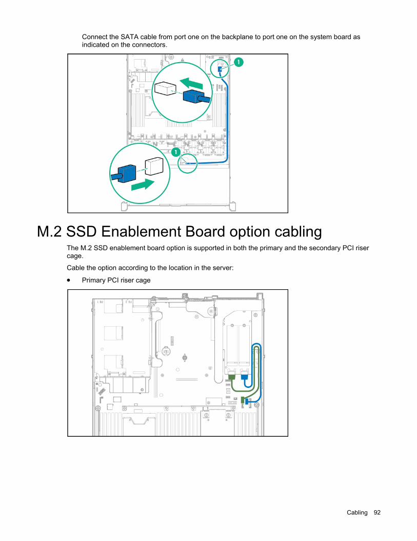
Cabling 92
Connect the SATA cable from port one on the backplane to port one on the system board as indicated on the connectors.
M.2 SSD Enablement Board option cabling The M.2 SSD enablement board option is supported in both the primary and the secondary PCI riser cage.
Cable the option according to the location in the server:
• Primary PCI riser cage
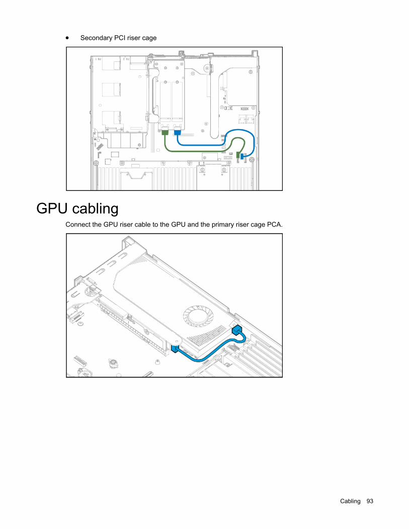
Cabling 93
• Secondary PCI riser cage
GPU cabling Connect the GPU riser cable to the GPU and the primary riser cage PCA.

Specifications 94
Specifications
Environmental specifications
Specification Value Temperature range* —
Operating 10°C to 35°C (50°F to 95°F)
Nonoperating -30°C to 60°C (-22°F to 140°F)
Relative humidity (noncondensing)
—
Operating Minimum to be the higher (more moisture) of -12°C (10.4°F) dew point or 8% relative humidity Maximum to be 24°C (75.2°F) dew point or 90% relative humidity
Nonoperating 5% to 95% 38.7°C (101.7°F), maximum wet bulb temperature
* All temperature ratings shown are for sea level. An altitude derating of 1.0°C per 304.8 m (1.8°F per 1000 ft) to 3048 m (10,000 ft) is applicable. No direct sunlight allowed. Maximum rate of change is 20°C per hour (36°F per hour). The upper limit and rate of change might be limited by the type and number of options installed.
For certain approved hardware configurations, the supported system inlet temperature range is extended:
• 5°C to 10°C (41°F to 50°F) and 35°C to 40°C (95°F to 104°F) at sea level with an altitude derating of 1.0°C per every 175 m (1.8°F per every 574 ft) above 900 m (2953 ft) to a maximum of 3048 m (10,000 ft).
• 40°C to 45°C (104°F to 113°F) at sea level with an altitude derating of 1.0°C per every 125 m (1.8°F per every 410 ft) above 900 m (2953 ft) to a maximum of 3048 m (10,000 ft).
The approved hardware configurations for this system are listed on the Hewlett Packard Enterprise website (http://www.hpe.com/servers/ASHRAE).
Server specifications
Specification Value Height 4.29 cm (1.69 in)
Depth (chassis with SFF drive cage) 69.90 cm (27.50 in)
Depth (chassis with LFF drive cage) 74.98 cm (29.50 in)
Width 43.46 cm (17.11 in)
Weights
SFF minimum (one drive, one processor, one power supply, two heatsinks, one Smart Array controller, five fans)
12.25 kg (27.00 lb)
SFF maximum (10 drives, two processors, two power supplies, two heatsinks, one Smart Array
15.31 kg (33.36 lb)

Specifications 95
Specification Value controller, seven fans) LFF minimum (one drive, one processor, one power supply, two heatsinks, one Smart Array controller, five fans)
13.77 kg (30.36 lb)
LFF maximum (Four drives, two processors, two power supplies, two heatsinks, one Smart Array controller, seven fans)
16.78 kg (37 lb)
Power supply specifications Depending on installed options, the server is configured with one of the following power supplies:
• HPE 500W Flex Slot Platinum Hot-plug Power Supply
• HPE 800W Flex Slot Platinum Hot-plug Power Supply (on page 96)
• HPE 800W Flex Slot Titanium Plus Hot-plug Power Supply (on page 96)
• HPE 800W Flex Slot Universal Hot-plug Power Supply (on page 97)
• HPE 800W Flex Slot -48VDC Hot-plug Power Supply (on page 97)
• HPE 1400W Flex Slot Platinum Plus Hot-plug Power Supply (on page 98)
For detailed power supply specifications, see the QuickSpecs on the Hewlett Packard Enterprise website (http://www.hpe.com/info/proliant/powersupply).
HPE 500W Flex Slot Platinum Hot-plug Power Supply
Specification Value Input requirements Rated input voltage 100 to 127 VAC
200 to 240 VAC 240 VDC for China only
Rated input frequency 50 Hz to 60 Hz Not applicable to 240 VDC
Rated input current 5.8 A at 100 VAC 2.8 A at 200 VAC 2.4 A at 240 VDC for China only
Maximum rated input power 580 W at 100 VAC 560 W at 200 VAC 576 W at 240 VDC for China only
BTUs per hour 1979 at 100 VAC 1911 at 200 VAC 1965 at 240 VDC for China only
Power supply output Rated steady-state power 500 W at 100 VAC to 127 VAC
input 500 W at 200 VAC to 240 VAC input 500 W at 240 VDC input for China only
Maximum peak power 500 W at 100 VAC to 127 VAC input

Specifications 96
500 W at 200 VAC to 240 VAC input 500 W at 240 VDC input for China only
HPE 800W Flex Slot Platinum Hot-plug Power Supply
Specification Value Input requirements Rated input voltage 100 to 127 VAC
200 to 240 VAC 240 VDC for China only
Rated input frequency 50 Hz to 60 Hz Not applicable to 240VDC
Rated input current 9.4 A at 100 VAC 4.5 A at 200 VAC 3.8 A at 240 VDC for China only
Maximum rated input power 940 W at 100 VAC 900 W at 200 VAC 912 W at 240 VDC for China only
BTUs per hour 3207 at 100 VAC 3071 at 200 VAC 3112 at 240 for China only
Power supply output Rated steady-state power 800 W at 100 VAC to 127 VAC
input 800 W at 200 VAC to 240 VAC input 800 W at 240 VDC input for China only
Maximum peak power 800 W at 100 VAC to 127 VAC input 800 W at 200 VAC to 240 VAC input 800 W at 240 VDC input for China only
HPE 800W Flex Slot Titanium Plus Hot-plug Power Supply
Specification Value Input requirements Rated input voltage 200 to 240 V AC
240 VDC for China only
Rated input frequency 50 Hz to 60 Hz Not applicable to 240 VDC
Rated input current 4.35 A at 200 VAC 3.62 A at 240 VAC 3.62 A at 240 VDC for China only
Maximum rated input power 870 W at 200 VAC 870 W at 240 VAC 870 W at 240 VDC for China only
BTUs per hour 2969 at 200 VAC 2969 at 240 VAC 2969 at 240 VDC for China only

Specifications 97
Power supply output Rated steady-state power 800 W at 200 VAC to 240 VAC
input 800 W at 240 VDC input for China only
Maximum peak power 800 W at 200 VAC to 240 VAC input 800 W at 240 VDC input for China only
HPE 800W Flex Slot Universal Hot-plug Power Supply
Specification Value Input requirements
Rated input voltage 200 V to 277 V AC 380 VDC
Rated input frequency 50 Hz–60 Hz
Rated input current 4.5 A at 200 V AC 3.2 A at 277 V AC 2.3 A at 380 VDC
Maximum rated input power 900 W at 200 VAC 887 W at 277 VAC 874 W at 380 VDC
BTUs per hour 3071 at 200 VAC 3026 at 277 VAC 2982 at 380 VDC
Power supply output
Rated steady-state power 800 W at 200 VAC to 277 VAC input 800 W at 380 VDC input
Maximum peak power 800 W at 200 VAC to 277 VAC input 800 W at 380 VDC input
HPE 800W Flex Slot -48VDC Hot-plug Power Supply
Specification Value Input requirements
Rated input voltage -40 VDC to -72 VDC -48 VDC nominal input
Rated input current 26 A at -40 VDC input 19 A at -48 VDC input, nominal input 12.4 A at -72 VDC input
Rated input power (W) 936 W at -40 VDC input 912 W at -48 VDC input, nominal input 900 W at -72 VDC input
Rated input power (BTUs per hour)
3194 at -40 VDC input 3112 at -48 VDC input, nominal input 3071 at -72 VDC input
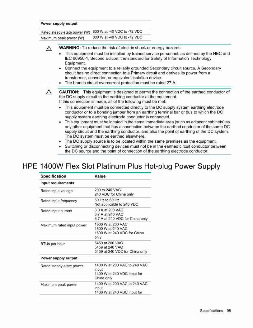
Specifications 98
Power supply output
Rated steady-state power (W) 800 W at -40 VDC to -72 VDC
Maximum peak power (W) 800 W at -40 VDC to -72 VDC
WARNING: To reduce the risk of electric shock or energy hazards: • This equipment must be installed by trained service personnel, as defined by the NEC and
IEC 60950-1, Second Edition, the standard for Safety of Information Technology Equipment.
• Connect the equipment to a reliably grounded Secondary circuit source. A Secondary circuit has no direct connection to a Primary circuit and derives its power from a transformer, converter, or equivalent isolation device.
• The branch circuit overcurrent protection must be rated 27 A.
CAUTION: This equipment is designed to permit the connection of the earthed conductor of the DC supply circuit to the earthing conductor at the equipment. If this connection is made, all of the following must be met: • This equipment must be connected directly to the DC supply system earthing electrode
conductor or to a bonding jumper from an earthing terminal bar or bus to which the DC supply system earthing electrode conductor is connected.
• This equipment must be located in the same immediate area (such as adjacent cabinets) as any other equipment that has a connection between the earthed conductor of the same DC supply circuit and the earthing conductor, and also the point of earthing of the DC system. The DC system must be earthed elsewhere.
• The DC supply source is to be located within the same premises as the equipment. • Switching or disconnecting devices must not be in the earthed circuit conductor between
the DC source and the point of connection of the earthing electrode conductor.
HPE 1400W Flex Slot Platinum Plus Hot-plug Power Supply
Specification Value Input requirements Rated input voltage 200 to 240 VAC
240 VDC for China only
Rated input frequency 50 Hz to 60 Hz Not applicable to 240 VDC
Rated input current 8.0 A at 200 VAC 6.7 A at 240 VAC 6.7 A at 240 VDC for China only
Maximum rated input power 1600 W at 200 VAC 1600 W at 240 VAC 1600 W at 240 VDC for China only
BTUs per hour 5459 at 200 VAC 5459 at 240 VAC 5459 at 240 VDC for China only
Power supply output Rated steady-state power 1400 W at 200 VAC to 240 VAC
input 1400 W at 240 VDC input for China only
Maximum peak power 1400 W at 200 VAC to 240 VAC input 1400 W at 240 VDC input for
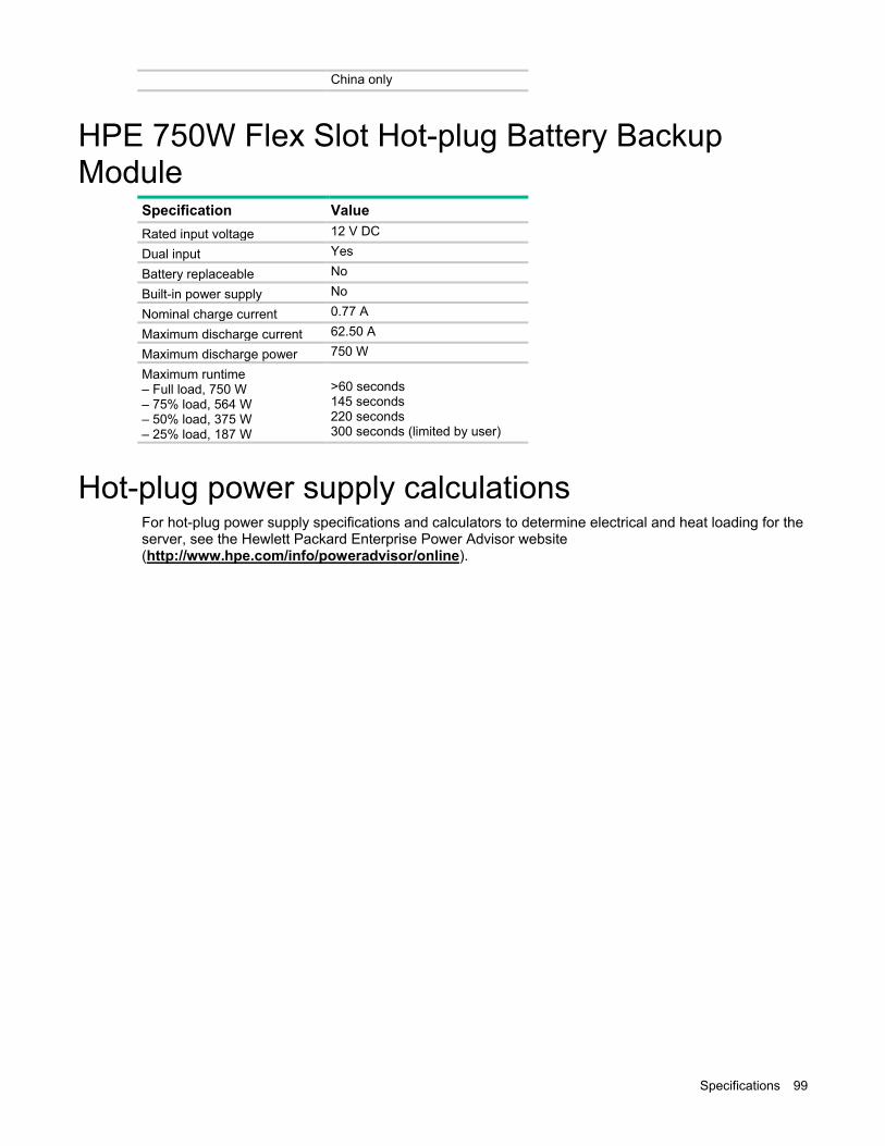
Specifications 99
China only
HPE 750W Flex Slot Hot-plug Battery Backup Module
Specification Value Rated input voltage 12 V DC
Dual input Yes
Battery replaceable No
Built-in power supply No
Nominal charge current 0.77 A
Maximum discharge current 62.50 A
Maximum discharge power 750 W
Maximum runtime – Full load, 750 W – 75% load, 564 W – 50% load, 375 W – 25% load, 187 W
>60 seconds 145 seconds 220 seconds 300 seconds (limited by user)
Hot-plug power supply calculations For hot-plug power supply specifications and calculators to determine electrical and heat loading for the server, see the Hewlett Packard Enterprise Power Advisor website (http://www.hpe.com/info/poweradvisor/online).

Acronyms and abbreviations 100
Acronyms and abbreviations
AMP Advanced Memory Protection
API application program interface
ASHRAE American Society of Heating, Refrigerating and Air-Conditioning Engineers
CSR Customer Self Repair
FLR FlexibleLOM for rack servers
FSBBU Flex slot battery backup
GPU graphics processing unit
HBA host bus adapter
HPE SIM HPE Systems Insight Manager
IEC International Electrotechnical Commission
iLO Integrated Lights-Out
IML Integrated Management Log
LFF large form factor

Acronyms and abbreviations 101
NMI nonmaskable interrupt
NVRAM nonvolatile memory
PCIe Peripheral Component Interconnect Express
POST Power-On Self Test
RBSU ROM-Based Setup Utility
REST representational state transfer
RSOC relative state of change
SAS serial attached SCSI
SATA serial ATA
SD Secure Digital
SFF small form factor
SPP Standard Parallel Port Mode
SSD solid-state drive
SUV serial, USB, video
TPM Trusted Platform Module

Acronyms and abbreviations 102
UEFI Unified Extensible Firmware Interface
UID unit identification
USB universal serial bus
VDC voltage direct-current

Documentation feedback 103
Documentation feedback
Hewlett Packard Enterprise is committed to providing documentation that meets your needs. To help us improve the documentation, send any errors, suggestions, or comments to Documentation Feedback (mailto:[email protected]). When submitting your feedback, include the document title, part number, edition, and publication date located on the front cover of the document. For online help content, include the product name, product version, help edition, and publication date located on the legal notices page.

Index 104
4 4X SFF Smart Array enable option 44
A AC power supply 24, 95, 96, 97 access panel 26 assembly 34, 35
B backplane, drive 44, 46, 47 battery backup module 25, 99 battery backup, battery check button 78 battery backup, LED 78 battery check button 78 button, battery check 78 buttons 71, 73
C cables 86 cabling 86, 90, 91, 92 cautions 20 components 5, 16, 71 components, identification 5, 71 components, system board 80 connectors 71
D diagnostic tools 68 DIMM slot locations 81 drive bays 71, 82 drive cage assembly 41, 44 drive LEDs 83 drives 22, 71, 83 drives, configuring 22
E electrostatic discharge 20 environmental specifications 94 error messages 67 expansion boards 51 Express Bay enablement option 44 extend server from rack 17
F fan module location 32, 33
fans 32, 33 features 71 flex slot battery backup module, battery check
button 78 flex slot battery backup module, LED 78 FlexibleLOM 49 front panel buttons 72 front panel components 71 front panel LEDs 72 FSBBU module 25, 99 FSBBU, battery check button 78 FSBBU, LED 78
G GPU 31 GPU cabling 31 GPU riser board 31 grounding methods 20 grounding requirements 20
H hard drive backplane 46, 47 hard drive LEDs 83 hard drives, determining status of 83 health LEDs 72 heatsink 54, 55 hot-plug fans 84 HP Insight Diagnostics 16
I illustrated parts catalog 5 iLO (Integrated Lights-Out) 68, 69, 70 IML (Integrated Management Log) 70 Integrated Lights-Out (iLO) 69, 70 Integrated Management Log (IML) 70
L LED, FSBBU module 78 LED, system power 72 LEDs 75, 83 LEDs, front panel 83 LEDs, hard drive 83 LEDs, NIC 72 LEDs, power supply 74, 77 LEDs, SAS hard drive 83 LEDs, troubleshooting 67 LEDs, unit identification (UID) 77 location discovery services 39
Index

Index 105
M M.2 SSD cabling 92 M.2 SSD enablement board 52 M.2 SSD enablement option 92 maintenance 16 management tools 68 mechanical components 5
N NIC connectors 76 NMI header 80 non-hot-plug PCI riser board slot definitions 81 NVMe SSD 83
O optical drive 34, 35
P part numbers 5 PCIe riser blank 29, 30 PCIe riser cage 26, 28 POST error messages 67 power LEDs, system 72 Power On button 72 power supply 24, 99 power supply blank 24 power supply LEDs 74 power supply specifications 95, 96, 98 powering down 16 preparation procedures 16 problem diagnosis 67, 68 processors 56
Q QuickSpecs 68
R rack, extending server from 17, 20 rear panel buttons 77 rear panel components 76 rear panel LEDs 77 rear panel, accessing 18 removal and replacement procedures 16 remove server from rack 17
S safety considerations 20 serial connector 76 Smart Array controller 90 software 69 spare part numbers 5 specifications 94, 99 specifications, environmental 94
specifications, power 95, 96, 97, 98 specifications, server 94 static electricity 20 symbols on equipment 21 system battery 59 system board components 79 system components 71 system power LED 72 Systems Insight Display 37, 38, 75 Systems Insight Display LEDs 74, 75
T telco racks 16 temperature requirements 94 tools 16 TPM (Trusted Platform Module) 65 troubleshooting 67
U UID LED 77 USB connector 71 USB support 34, 35 utilities 68
V video connector 71