hr10/12 (sp26/34) parts manual - niftylift.com · descripciones contenidas en el presente documento...
TRANSCRIPT

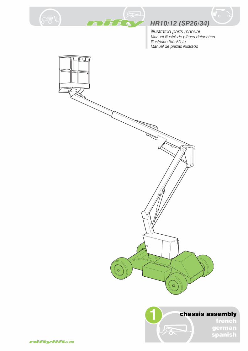
HR10/12SP26/34
illustrated parts manual
Manuel illustré de pièces détachées
Illustrierte Stückliste
Manual de piezas ilustrado
M50190/09
Issue 9(December 2010)


HR10/12 (SP26/34)
illustrated parts manualManuel illustré de pièces détachées Illustrierte Stückliste Manual de piezas ilustrado
Please Note, at the time of going to press, all information, illustrations details and descriptions contained herein are valid. Niftylift reserves the right to change, alter, modify or improve its products without any obligation to install them on previously manufactured machines.
Readers of this manual requiring further information should contact us at:
Niftylift Ltd. Niftylift Inc.Fingle Drive 32 Concourse WayStonebridge GreerMilton Keynes SC 29651MK13 OER USAUnited Kingdom
Tel +44 (0)1908 857899 1 864 968 8881Fax +44 (0)1908 227460 1 864 968 8836
Ordering of PartsWhen ordering a replacement part for your Niftylift product, please state the following:
• Machine Model and Serial number Niftylift Part number
• Full description of the part Quantity required
• Purchase Order number Destination address
Machine Information
Model number. . . . . . . . . . . . . . . . . . . . . . . . . . . . . Date of Purchase. . . . . . . . . . . . . .
Serial number . . . . . . . . . . . . . . . . . . . . . . . . . . . . .
Veuillez noter qu'au moment de la mise sous presse, l'ensemble des informations, illustrations, détails et descriptions, contenus dans le présent document, sont valides. Niftylift se réserve le droit de changer ou d'améliorer ses produits sans obligation de montage sur les anciennes machines.
Pour toutes informations supplémentaires, veuillez nous contacter à:
Niftylift Ltd. Niftylift Inc.Fingle Drive 32 Concourse WayStonebridge GreerMilton Keynes SC 29651MK13 OER USAUnited Kingdom
Tel +44 (0)1908 857899 1 864 968 8881Fax +44 (0)1908 227460 1 864 968 8836
Commande de piècesLors de la commande de pièces de rechange pour votre machine Niftylift, veuillez indiquer ce qui suit:
• Modèle et numéro de série de la machine Référence de la pièce Niftylift
• Description complète de la pièce Quantité requise
• Numéro de commande Adresse de destination
Informations relatives à la machine
Numéro de modèle . . . . . . . . . . . . . . . . . . . . . . . . . . . Date d'achat . . . . . . . . . . . . . . . . . . .
Numéro de série . . . . . . . . . . . . . . . . . . . . . . . . . . . . .

HR10/12 (SP26/34)
iv issue 09
illustrated parts manual Manuel illustré de pièces détachées Illustrierte Stückliste Manual de piezas ilustrado
Bitte nehmen Sie zur Kenntnis, dass alle hierin enthaltenen Informationen, Illustrationen und Beschreibungen zum Zeitpunkt des Drucks gültig sind. Niftylift behält sich das Recht vor, Produkte zu wechseln, ändern, modifizieren und zu verbessern, ohne verpflichtet zu sein, sie an früher gefertigten Maschinen zu installieren.Wenn Leser dieser Anleitung weitere Informationen benötigen, wenden sie sich bitte an uns unter:
Niftylift Ltd. Niftylift Inc.Fingle Drive 32 Concourse WayStonebridge GreerMilton Keynes SC 29651MK13 OER USAGroßbritannien
Tel +44 (0)1908 857899 1 864 968 8881Fax +44 (0)1908 227460 1 864 968 8836
Bestellen von ErsatzteilenBei der Bestellung eines Ersatzteils für Ihr Produkt von Niftylift geben Sie bitte folgende Einzelheiten an:
• Maschinenmodell und Seriennummer Niftylift Art.-Nr.
• Ausführliche Beschreibung des Teils Erforderliche Menge
• Bestellnummer Bestimmungsadresse
Maschineninformationen
Modellnummer . . . . . . . . . . . . . . . . . . . . . . . . . . . . . . Kaufdatum . . . . . . . . . . . . . . . . . . . .
Seriennummer . . . . . . . . . . . . . . . . . . . . . . . . . . . . . . .
Por favor, observe que en el momento de pasar a imprenta, toda la información, ilustraciones y descripciones contenidas en el presente documento eran válidas. Niftylift se reserva el derecho de cambiar, alterar, modificar o mejorar sus productos, sin obligación alguna de instalar dichos cambios en máquinas fabricadas anteriormente.Los usuarios de este manual que requieran más información, deberán ponerse en contacto con nosotros en:
Niftylift Ltd. Niftylift Inc.Fingle Drive 32 Concourse WayStonebridge GreerMilton Keynes SC 29651MK13 OER USAUnited Kingdom
Tel +44 (0)1908 857899 1 864 968 8881Fax +44 (0)1908 227460 1 864 968 8836
Pedido de piezasAl realizar el pedido de una pieza de recambio para su producto Niftylift, sírvase especificar lo siguiente:
• Modelo y número de serie de la máquina Número de pieza Niftylift
• Descripción completa de la pieza Cantidad requerida
• Número de orden de compra Dirección de destino
Información de la máquina
Número de modelo . . . . . . . . . . . . . . . . . . . . . . . . . . . Fecha de compra . . . . . . . . . . . . . . .
Número de serie . . . . . . . . . . . . . . . . . . . . . . . . . . . . .
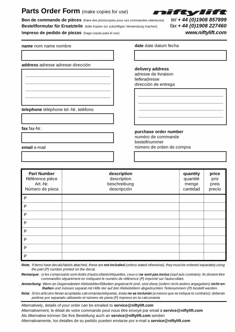
Parts Order Form (make copies for use)
Bon de commande de pièces (Faire des photocopies pour vos commandes ultérieures) tel +44 (0)1908 857899Bestellformular für Ersatzteile (bitte Kopien zur zukünftigen Verwendung machen) fax +44 (0)1908 227460Impreso de pedido de piezas (haga copias para el uso) www.niftylift.com
Note; If items have decals/labels attached, these are not included (unless stated otherwise), they must be ordered separately using the part (P) number printed on the decal.
Remarque : si les composants sont dotés d'autocollants/étiquettes, ceux-ci ne sont pas inclus (sauf avis contraire). Ils doivent être commandés séparément en indiquant le numéro de référence (P) imprimé sur l'autocollant.
Anmerkung: Wenn an Gegenständen Klebebilder/Etiketten angebracht sind, sind diese (sofern nicht anders angegeben) nicht en-thalten und müssen separat mit Hilfe der auf den Klebebildern abgedruckten Teilenummern (P) bestellt werden.
Nota: Si los artículos llevan acopladas calcomanías/etiquetas, éstas no se incluirán (a menos que se indique lo contrario); deberán pedirse por separado utilizando el número de pieza (P) impreso en la calcomanía.
Alternatively, details of your order can be emailed to [email protected], le détail de votre commande peut nous être envoyé par email à [email protected] Alternative können Sie Ihre Bestellung auch an [email protected] sendenAlternativamente, los detalles de su pedido pueden enviarse por e-mail a [email protected]
Part NumberRéférence pièce
Art.-Nr.Número de pieza
descriptiondescription
beschreibungdescripción
quantityquantitémenge
cantidad
priceprix
preisprecio
P
P
P
P
P
P
P
P
name nom name nombre
address adresse adresse dirección
telephone téléphone tel.-Nr. teléfono
fax fax-Nr.
email e-mail
date date datum fecha
delivery addressadresse de livraisonlieferadressedirección de entrega
purchase order numbernuméro de commandebestellnummernúmero de orden de compra

HR10/12 (SP26/34)
vi
illustrated parts manual Manuel illustré de pièces détachées Illustrierte Stückliste Manual de piezas ilustrado
tab
le d
es m
atiè
res
inh
alts
verz
eich
nis
tab
la d
el c
ont
enid
oco
nten
ts
issue 09
1 chassis page
1.1 Base assembly ...................................................................................................... 1-2
1.2 Bonnets/Covers & Guards .................................................................................... 1-4
1.3 Steering assembly................................................................................................. 1-6
1.4 Front hub assembly .............................................................................................. 1-8
1.5 Power pack.......................................................................................................... 1-10
1.6 Drive control valve............................................................................................... 1-12
1.7 Diesel Engine (Part 1) ......................................................................................... 1-14
1.8 Diesel Engine (Part 2) ......................................................................................... 1-16
1.9 Diesel box............................................................................................................ 1-18
1.10 Anderson connector............................................................................................ 1-20
2 superstructure page
2.1 Control station - Base............................................................................................ 2-2
2.2 Slew assembly ...................................................................................................... 2-4
2.3 Control valve assembly (3 spool) ......................................................................... 2-6
2.4 Control valve assembly (4 spool) ......................................................................... 2-8
2.5 Button box assembly........................................................................................... 2-10
2.6 Control box.......................................................................................................... 2-12
2.7 Dual voltage charger box .................................................................................... 2-14
2.8 Battery charger.................................................................................................... 2-16
3 boom assemblies page
3.1 HR10/SP26 Booms assembly............................................................................... 3-2
3.2 HR12/SP34 Booms assembly............................................................................... 3-4
3.3 HR10/SP26 Lift cylinder ........................................................................................ 3-8
3.4 HR12/SP34 Lift cylinder ...................................................................................... 3-10
3.5 Levelling cylinder................................................................................................. 3-12
3.6 Telescope cylinder .............................................................................................. 3-14
3.7 Energy chain ...................................................................................................... 3-16
4 cage page
4.1 Cage assembly...................................................................................................... 4-2
4.2 Cage weigh assembly - Spring (HR10) ................................................................ 4-4
4.3 Cage weigh assembly - Load Cell (HR10)............................................................ 4-6
4.4 Cage weigh assembly - Spring (HR12) ................................................................ 4-8
4.5 Cage weigh assembly - Load Cell (HR12).......................................................... 4-10
4.6 Control box - Cage .............................................................................................. 4-12
4.7 Control valve - Cage............................................................................................ 4-14

HR10/12 (SP26/34)
cont
ents
illustrated parts manualManuel illustré de pièces détachées Illustrierte Stückliste Manual de piezas ilustrado
tab
le d
es m
atiè
res
inh
alts
verz
eich
nis
tab
la d
el c
ont
enid
o
issue 09
5 labellingpage
5.1 Label locations HR10/12........................................................................................ 5-2
5.2 Label locations SP26/34 (USA) ........................................................................... 5-18
6 hydraulic hosespage
6.1 Hose kit HR10 (SP26) ............................................................................................ 6-2
6.2 Hose kit HR12 (SP34) ............................................................................................ 6-4
Figures page
1.1 Base assembly ................................................................................. 1-3
1.2 Bonnets/Covers & Guards ................................................................ 1-5
1.3 Steering assembly............................................................................. 1-7
1.4 Front hub assembly .......................................................................... 1-9
1.5 Power pack (Hydr-app)................................................................... 1-11
1.6 Drive control valve ........................................................................... 1-13
1.7 Diesel Engine (Part 1) ..................................................................... 1-15
1.8 Diesel Engine (Part 2) ..................................................................... 1-17
1.9 Diesel box........................................................................................ 1-19
1.10 Anderson connector........................................................................ 1-21
2.1 Control station - Base........................................................................ 2-3
2.2 Slew assembly .................................................................................. 2-5
2.3 Control valve assembly (3 spool)...................................................... 2-7
2.4 Control valve assembly (4 spool)...................................................... 2-9
2.5 Button box assembly....................................................................... 2-11
2.6 Control box...................................................................................... 2-13
2.7 Dual voltage charger box ................................................................ 2-15
2.8 Battery charger................................................................................ 2-17
3.1 HR10/SP26 Booms assembly........................................................... 3-3
3.2 HR12/SP34 Booms assembly........................................................... 3-5
3.3 HR10/SP26 Lift cylinder .................................................................... 3-9
3.4 HR12/SP34 Lift cylinder .................................................................. 3-11
3.5 Levelling cylinder............................................................................. 3-13
3.6 Telescope cylinder .......................................................................... 3-15
3.7 Energy chain .................................................................................. 3-17
4.1 Cage assembly.................................................................................. 4-3
4.2 Cage weigh assembly - Spring (HR10) ............................................ 4-5
4.3 Cage weigh assembly - Load Cell (HR10)....................................... 4-7
4.4 Cage weigh assembly - Spring (HR12) ............................................ 4-9
4.5 Cage weigh assembly - Load Cell (HR12)..................................... 4-11
4.6 Control box - Cage .......................................................................... 4-13
4.7 Control valve - Cage........................................................................ 4-15

HR10/12 (SP26/34)
viii issue 09
illustrated parts manual Manuel illustré de pièces détachées Illustrierte Stückliste Manual de piezas ilustrado
5.1 Label locations HR10/12................................................................... 5-3
5.2 Label locations SP26/34 (USA) ...................................................... 5-19
5.3 Labels (1-33) ................................................................................... 5-20
5.4 Labels (34-43) ................................................................................. 5-21
6.1 Hose connections HR10 (SP26)....................................................... 6-3
6.2 Hose connections HR12 (SP34)....................................................... 6-5
Issue Records
Chapter Pages Issue Date Comments/Changes
Introduction 8 9 12/2010 Ninth issue
1 22 9 05/2011 Revised for ‘Power packs’ (Pages 1-2 and 1-10/11)
2 18 7 07/2010 Revised for ‘Button box’ (Pages 2-10/11)
3 18 7 08/2009 Revised for ‘Energy chain’ (Pages 3-16/17)
4 16 8 11/2010 Revised for ‘Level cylinder’ (Pages 4-8 to 4-10)
5 22 6 02/2009 Sixth issue
6 10 2 03/2006 Second issue
* When ordering parts for machines other than the stated serial number,it is advisable to contact the Parts Department;
United Kingdom USA
Tel +44 (0)1908 857899 1 864 968 8881Fax +44 (0)1908 227460 1 864 968 8836Email [email protected] [email protected]
HR10/12 (SP26/34)
1
illustrated parts manualManuel illustré de pièces détachéesIllustrierte StücklisteManual de piezas ilustrado
chassis assemblyfrench
germanspanish

HR10/12 (SP26/34)illustrated parts manual Manuel illustré de pièces détachées Illustrierte Stückliste Manual de piezas ilustrado
1–2
chas
sis
asse
mb
lyfr
ench
ger
man
span
ish
1.1 Base assemblyItem Description Part Number
1Anderson connectorsSee “Anderson con-nector” on page 1-20.
N/A
2 Tilt sensor P16109
3
Power pack LH (1.2 cc pump) -See “Power pack” on page 1-10.
P16210
4 Hydraulic oil tank -19 litres/5 gal (USA) P16288
5 Filler cap and filter P10136
6 Dipstick P11643
7 Grommet P11283
8 Bridge rectifier P15763
9 Junction box P16442
10Fuse - 125AFuse Holder
P12696P11976
11 Battery - 12 v P11975
12 Battery clamp P12295
13Base HR10
HR12HR12N
P20905P20020P20019
14 Regulator(Bi-energy only) P13637
15 Battery carrier(Bi-energy only) P10786
16 Battery - 6 v(E or DE Only) P10829
17Diesel control box -See “Diesel box” on page 1-18.
P13627
18 Hydraulic oil filter and bowl assembly P10137
19 Replacementcartridge for item 18 P10766
20
Power pack RH (2.2 cc pump) -See “Power pack” on page 1-10.
P16211
21 Gearbox P15698
22 * Seal kit for item 21 P18126
23 Terminal box assy P14370
issue 09* Not illustrated

HR10/12 (SP26/34)
fren
chg
erm
ansp
anis
hch
assi
s as
sem
bly
1–3
illustrated parts manualManuel illustré de pièces détachées Illustrierte Stückliste Manual de piezas ilustrado
issue 09
14
16
18
1
20
23
241
21
3
654
8 910
7
12
1315
17
2
11
19
22*
24Drive control valve -See “Drive control valve” on page 1-12.
P19617
Figure 1.1 Base Assembly

HR10/12 (SP26/34)illustrated parts manual Manuel illustré de pièces détachées Illustrierte Stückliste Manual de piezas ilustrado
1.2 Bonnets/Covers/GuardsItem Description Part Number
1Middle bonnet -
All modelsP12241
2 Handle P10241
3 Battery cover P10822
4
Front bonnet -
HR12 NarrowBi-energy
HR12 Wide and HR10 Bi-energy
P12237
P18000
5Front bonnet -HR10 and HR12 DC
P14241
6 Knob (M12 x 25) P10276
7 Knob (M10 x 20) P14482
8Rear bonnet -
All modelsP15359
9 Slew guard P20084
1–4
chas
sis
asse
mb
lyfr
ench
ger
man
span
ish
issue 09

HR10/12 (SP26/34)
fren
chg
erm
ansp
anis
hch
assi
s as
sem
bly
1–5
illustrated parts manualManuel illustré de pièces détachées Illustrierte Stückliste Manual de piezas ilustrado
issue 09
12
7
7
8
3
4
9
23
5
6
2
2
Figure 1.2 Bonnets/covers and guards

HR10/12 (SP26/34)illustrated parts manual Manuel illustré de pièces détachées Illustrierte Stückliste Manual de piezas ilustrado
chas
sis
asse
mb
lyfr
ench
ger
man
span
ish
1.3 Steering assemblyItem Description Part Number
1
Wheel and tyre (Solid)
HR10 LHHR10 RH
Non-marking(all models)
P10603P10698P10833
2
Hub assembly LHSee “Front hub assembly” on page 1-8.
P15361
3 Nitrotech washer P12731
4 Bearing washer P12732
5 Bush DU253230 P12421
6 Plastic washer P10035
7 Bush DU1825 P11798
8 King pin P10128
9 Steer pin P11330
10 Steer pin P11331
11
Wheel and tyre (Foam filled)
HR12 StandardHR12 Non-marking
P11685P21582
12 Wheel bolt(86 Nm Torque) P22001
13
Hub assembly RHSee “Front hub assembly” on page 1-8.
P15362
14
Track Rod -
HR12 Narrow / HR10
HR12 Wide
P11309
P11342
15 Steer cylinder P11313
16 * Seal kit for item 15 P12499
17 Spacer P11800
1–6issue 09
18 Bush DU1820 P11366
* Not illustrated

HR10/12 (SP26/34)
fren
chg
erm
ansp
anis
hch
assi
s as
sem
bly
1–7
illustrated parts manualManuel illustré de pièces détachées Illustrierte Stückliste Manual de piezas ilustrado
issue 09
�
��
�
��
�
�
�
�
��
��
�
�
�
���
��
��
��
�
�
�
Figure 1.3 Steering assembly

HR10/12 (SP26/34)illustrated parts manual Manuel illustré de pièces détachées Illustrierte Stückliste Manual de piezas ilustrado
1.4 Front hub assemblyItem Description Part Number
1 Grease cap P15450
2 Hub nut P15452
3 Hub washer P15451
4 Outer bearing P15449
5 Hub P18938
6 Oil seal P15447
7 Inner bearing P15448
8 Wheel bolt (86 Nm) P22001
1–8
chas
sis
asse
mb
lyfr
ench
ger
man
span
ish
issue 09

HR10/12 (SP26/34)
fren
chg
erm
ansp
anis
hch
assi
s as
sem
bly
1–9
illustrated parts manualManuel illustré de pièces détachées Illustrierte Stückliste Manual de piezas ilustrado
issue 09
�
�
�
�
�
� � �
Figure 1.4 Front hub assembly

HR10/12 (SP26/34)illustrated parts manual Manuel illustré de pièces détachées Illustrierte Stückliste Manual de piezas ilustrado
lyfr
ench
ger
man
span
ish
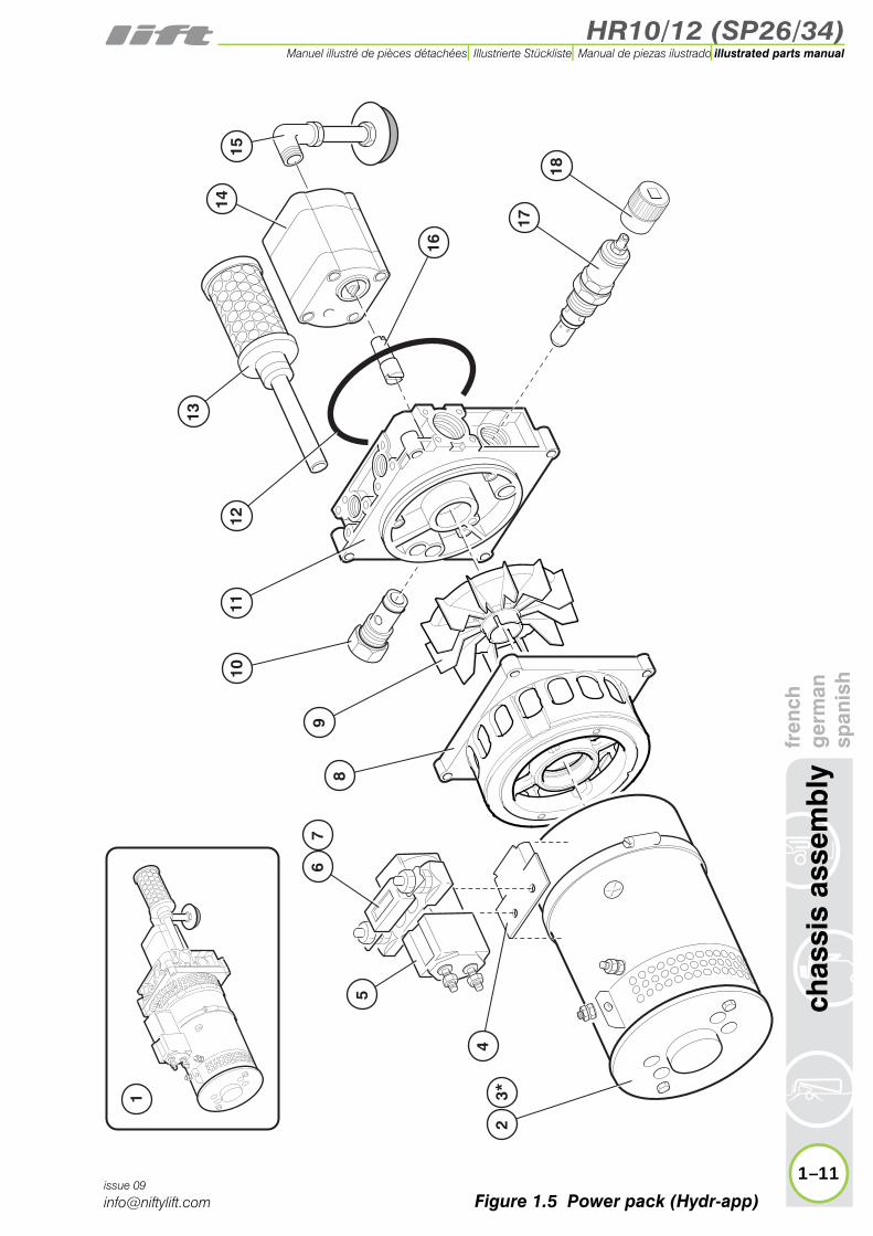
1.5 Power packItem Description Part Number
1Power pack assembly
1.2 cc2.2 cc
P16210P16211
2 Motor P16611
3 *
Brush & Spring Set for item 2
ISKRAHYDR-APP
P21151P16703
4 Contactor plate P16315
5
Contact solenoid -
12 v (Bi-energy)
24 v (DC only)
P11877P12922
6 Fuse - 225 A P11977
7 Fuse holder P11976
8 Flange - Motor P18153
9 Fan blade P22610
10 Check valve kit P16614
11 Flange - Centre P16612
12 O-ring P16616
13 Filter - Return line P16734
14Pump - 1.2 cc
2.2 ccP18172P16699
1–10
chas
sis
asse
mb
issue 09
15 Filter - suction P16700
16 Coupling P20063
17 Relief valve kit P16613
18 Cap P16615
* Not illustrated
HR10/12 (SP26/34)
fren
chg
erm
ansp
anis
hch
assi
s as
sem
bly
1–11
illustrated parts manualManuel illustré de pièces détachées Illustrierte Stückliste Manual de piezas ilustrado
issue 09
13
1415
1112
10
89
17
18
16
24
3*
5
67
1
Figure 1.5 Power pack (Hydr-app)

HR10/12 (SP26/34)illustrated parts manual Manuel illustré de pièces détachées Illustrierte Stückliste Manual de piezas ilustrado
fren
chg
erm
ansp
anis
h1.6 Drive control valve
Item Description Part Number
Complete assembly P19617
1 Coil - Divertersolenoid P15697
2 Diverter solenoid CT5 P19338
3 Brake release valveCT7 P15705
4 Diverter solenoidCT1 P19338
5 Overcentre valveCT8 P15706
6 Overcentre valveCT9 P19622
7Coil -
12 v brake solenoid
24 v brake solenoid
P15696
P15307
8Brake solenoid
CT13P16775
9 Check valveCT21 P12810
10 Check cartridgeCT10 & CT11 P15707
11 Check valveCT17 & CT18 P15709
1–12
chas
sis
asse
mb
ly
issue 09
12 Flow dividerCT3 P16776
13 Indicator valveCT20 P16777

HR10/12 (SP26/34)
fren
chg
erm
ansp
anis
hch
assi
s as
sem
bly
1–13
illustrated parts manualManuel illustré de pièces détachées Illustrierte Stückliste Manual de piezas ilustrado
issue 09
AB
A B
12
43
7
8
11
6
1
1112
9
5
10
13
10
Figure 1.6 Drive control valve
HR10/12 (SP26/34)illustrated parts manual Manuel illustré de pièces détachées Illustrierte Stückliste Manual de piezas ilustrado
has
sis
asse
mb
lyfr
ench
ger
man
span
ish
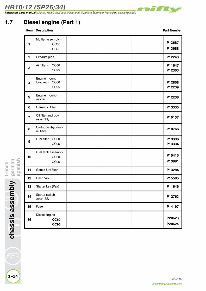
1.7 Diesel engine (Part 1)Item Description Part Number
1Muffler assembly -
OC60
OC95
P13687
P13688
2 Exhaust pipe P12243
3Air filter - OC60
OC95P11647P12303
4Engine mount bracket - OC60
OC95P12808P12239
5 Engine mount -rubber P12238
6 Gauze oil filter P13335
7 Oil filter and bowl assembly P10137
8 Cartridge - hydraulic oil filter P10766
9Fuel filter - OC60
OC95P13336P13334
10Fuel tank assembly
OC60
OC95
P15415
P13881
11 Gauze fuel filter P13284
12 Filler cap P15505
13 Starter key (Pair) P11646
14 Starter switch assembly P12763
15 Fuse P14197
16Diesel engine -
OC60
OC95
P20623
P20624
1–14
c
issue 09

HR10/12 (SP26/34)
fren
chg
erm
ansp
anis
hch
assi
s as
sem
bly
1–15
illustrated parts manualManuel illustré de pièces détachées Illustrierte Stückliste Manual de piezas ilustrado
issue 09
1
2
3
4
56
910
1112
13
1514
16
8
7
Figure 1.7 Diesel engine (1)

HR10/12 (SP26/34)illustrated parts manual Manuel illustré de pièces détachées Illustrierte Stückliste Manual de piezas ilustrado
ssem
bly
fren
chg
erm
ansp
anis
h1.8 Diesel engine (Part 2)
Item Description Part Number
1Diesel engine -
OC60
OC95
P20623
P20624
2Starter motor assy -
OC60
OC95
P11981
P13376
3Bracket - Throttle
(OC95 only)P12220
4 Throttle solenoid P12972
5 Spring P11135
6 Stop solenoid P70271
7 Bell housing P11499
8 Coupling P11500
9Pump assembly -
OC60
OC95
P11991
P12468
10 * Seal kit for item 9 P13367
11Valve cartridge - SH
IHP11927P16775
12Coil - SH
IHP11370P17947
13 Banjo bolt P11948
14Check valve - SH
IHP11928P17946
15 Manifold P11943
1–16
chas
sis
a
issue 09
16 Regulator P12640
* Not illustrated

HR10/12 (SP26/34)
fren
chg
erm
ansp
anis
hch
assi
s as
sem
bly
1–17
illustrated parts manualManuel illustré de pièces détachées Illustrierte Stückliste Manual de piezas ilustrado
issue 09
2
1
3
5
6
8
7
4
13
1514
10*
9
1112
16
Figure 1.8 Diesel engine (2)
HR10/12 (SP26/34)illustrated parts manual Manuel illustré de pièces détachées Illustrierte Stückliste Manual de piezas ilustrado
1.9 Diesel boxItem Description Part Number
Complete assembly P13627
1 ABS Box P12861
2 Capacitor P14270
3 Circuit breaker - 35 A P13529
4 Timer relay P10664
5 Relay P10340
6 Hour meter (OPTIONAL) P11410
1–18
chas
sis
asse
mb
lyfr
ench
ger
man
span
ish
issue 09

HR10/12 (SP26/34)
fren
chg
erm
ansp
anis
hch
assi
s as
sem
bly
1–19
illustrated parts manualManuel illustré de pièces détachées Illustrierte Stückliste Manual de piezas ilustrado
issue 09
1
5
6
4
3
2
Figure 1.9 Diesel box

HR10/12 (SP26/34)illustrated parts manual Manuel illustré de pièces détachées Illustrierte Stückliste Manual de piezas ilustrado
1.10 Anderson connectorItem Description Part Number
1 Handle P17084
2 Mounting plate P15271
3 Connector P17083
4 Connector - 12 v P17085
1–20
chas
sis
asse
mb
lyfr
ench
ger
man
span
ish
issue 09

HR10/12 (SP26/34)
fren
chg
erm
ansp
anis
hch
assi
s as
sem
bly
1–21
illustrated parts manualManuel illustré de pièces détachées Illustrierte Stückliste Manual de piezas ilustrado
issue 09
1
2
3
3
4
Figure 1.10 Anderson connector


HR10/12 (SP26/34)
2
illustrated parts manualManuel illustré de pièces détachéesIllustrierte StücklisteManual de piezas ilustrado
superstructurefrench
germanspanish

HR10/12 (SP26/34)illustrated parts manual Manuel illustré de pièces détachées Illustrierte Stückliste Manual de piezas ilustrado
sup
erst
ruct
ure
fren
chg
erm
ansp
anis
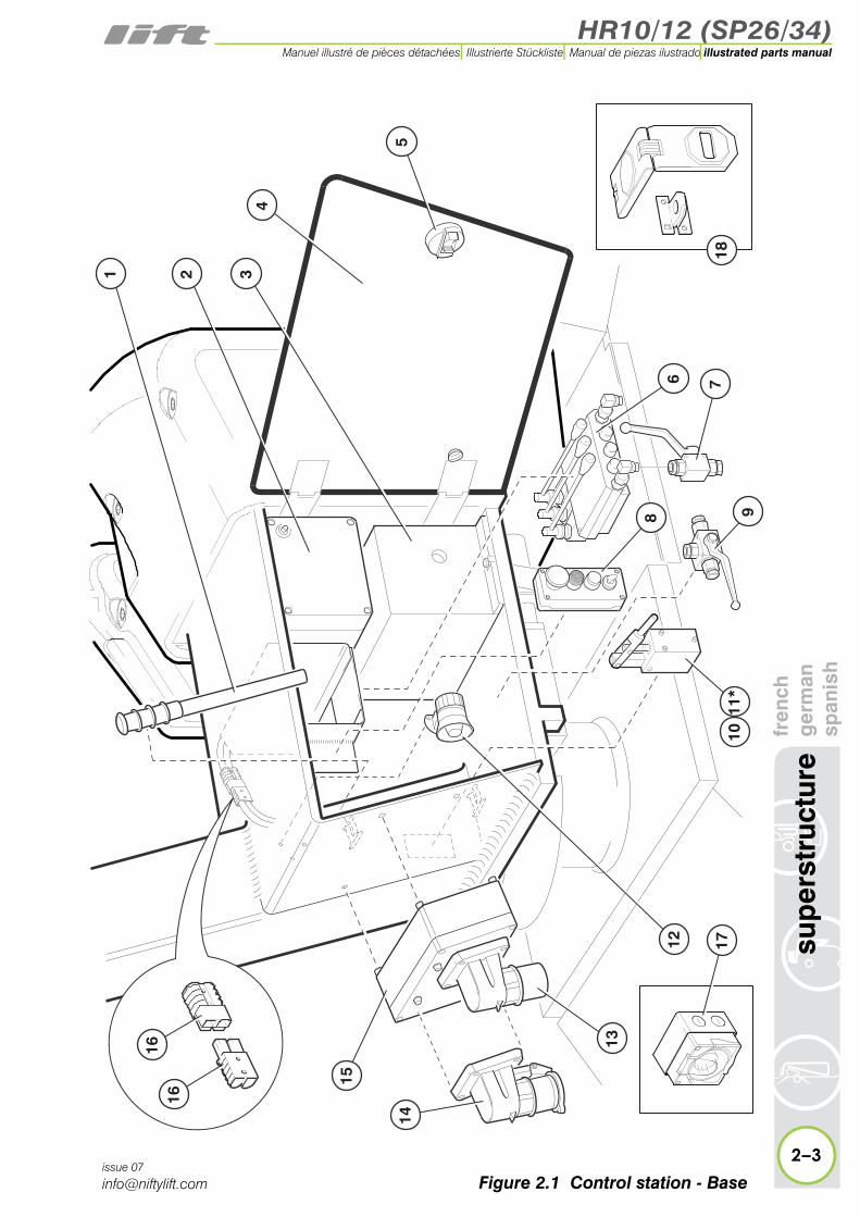
h2.1 Control station - Base
Item Description Part Number
1 Handle (Item 10) P10624
2
Control box 12 v24 v
See “Control box” on page 2-12.
P17135P17137
3
Battery Charger UKUSA
EuropeanSee “Battery charger” on page 2-16.
P12759P11751P11067
4 Access cover P20108
5 Door latch P12397
6
Control valve -
See “Control valve assembly (3 spool)” on page 2-6.
or “Control valve assembly (4 spool)” on page 2-8
P15514
P15518
7Diverter valve (3/8“)
Lever ONLY
P10702
P14397
8
Button box -
See “Button box assembly” on page 2-10.
N/A
9Diverter valve (1/4”)
Lever ONLY
P16050
P14397
10 Manual hand pump P22570
11 * Seal kit for item 10 P22605
12 Siren P11113
13 110 v inlet ONLY P20956
14 240 v inlet ONLY P20957
15
Dual voltage charger box -
See “Dual voltage charger box” on page 2-14.
P10599
16 Anderson connector (12 v) P17085
17 Socket 110v/16A(OPTIONAL) P10751
18 Door hasp (Option) P20836
2–2issue 07
* Not illustrated
HR10/12 (SP26/34)
fren
chg
erm
ansp
anis
hsu
per
stru
ctur
e
2–3
illustrated parts manualManuel illustré de pièces détachées Illustrierte Stückliste Manual de piezas ilustrado
issue 07
4
5
15
14
1616 13
6 7
9
17
8
1011*
321
12
18
Figure 2.1 Control station - Base

HR10/12 (SP26/34)illustrated parts manual Manuel illustré de pièces détachées Illustrierte Stückliste Manual de piezas ilustrado
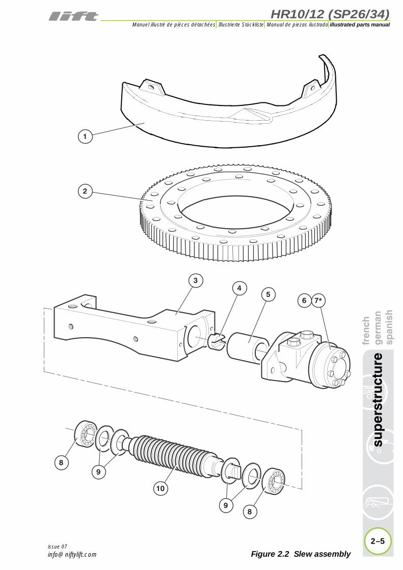
2.2 Slew assemblyItem Description Part Number
Complete assembly(Items 3 to 10) P19498
1 Slew guard P20084
2 Slew ring P16817
3 Worm bracket P12681
4 Coupling P12145
5 Spacer P12143
6 Motor P14306
Seal kit for item 6 P13242
8 Bearing P12703
7 *
2–4
sup
erst
ruct
ure
fren
chg
erm
ansp
anis
h
issue 07
9 Belleville washer P12150
10 Worm gear P14502
* Not illustrated
HR10/12 (SP26/34)
fren
chg
erm
ansp
anis
hsu
per
stru
ctur
e
2–5
illustrated parts manualManuel illustré de pièces détachées Illustrierte Stückliste Manual de piezas ilustrado
issue 07
34
5
1
2
8
10
89
9
6 7*
Figure 2.2 Slew assembly
HR10/12 (SP26/34)illustrated parts manual Manuel illustré de pièces détachées Illustrierte Stückliste Manual de piezas ilustrado
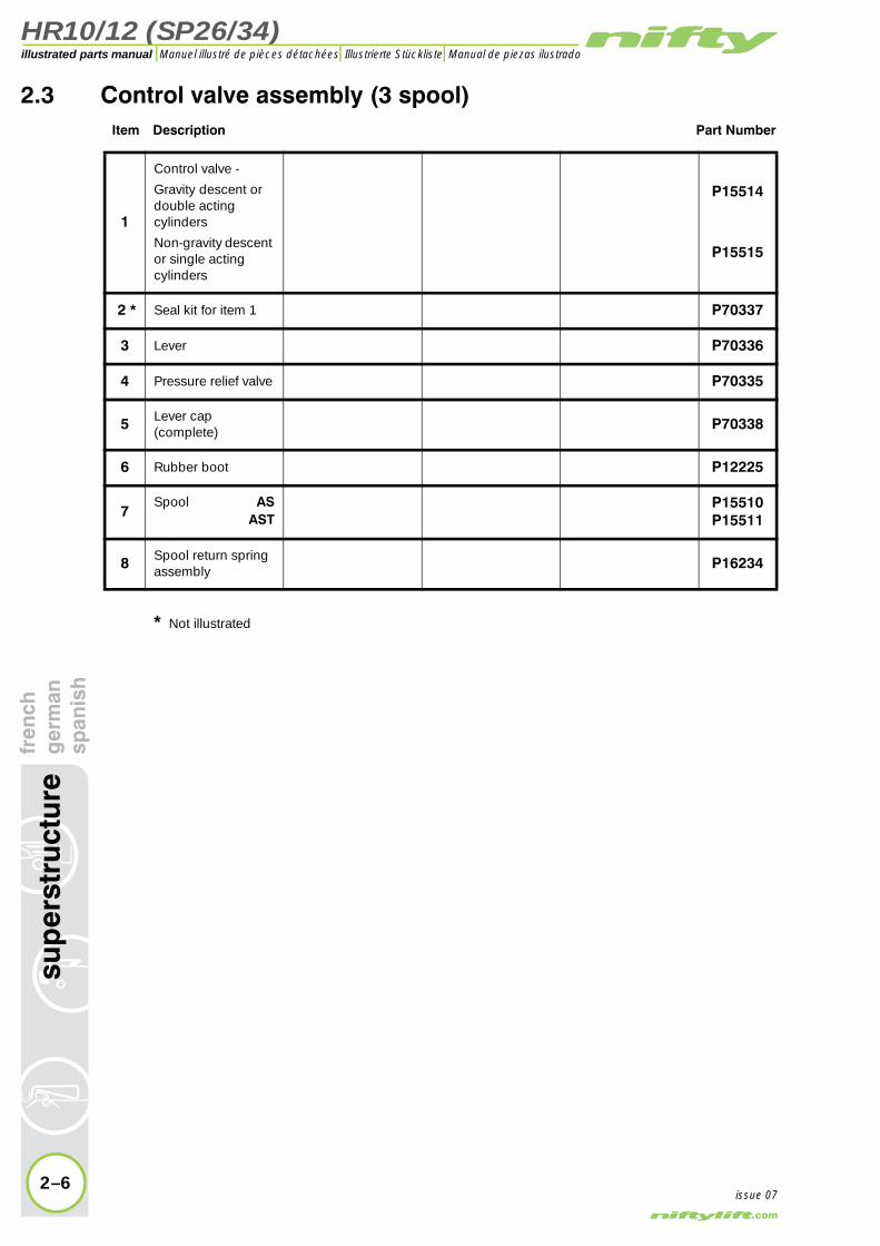
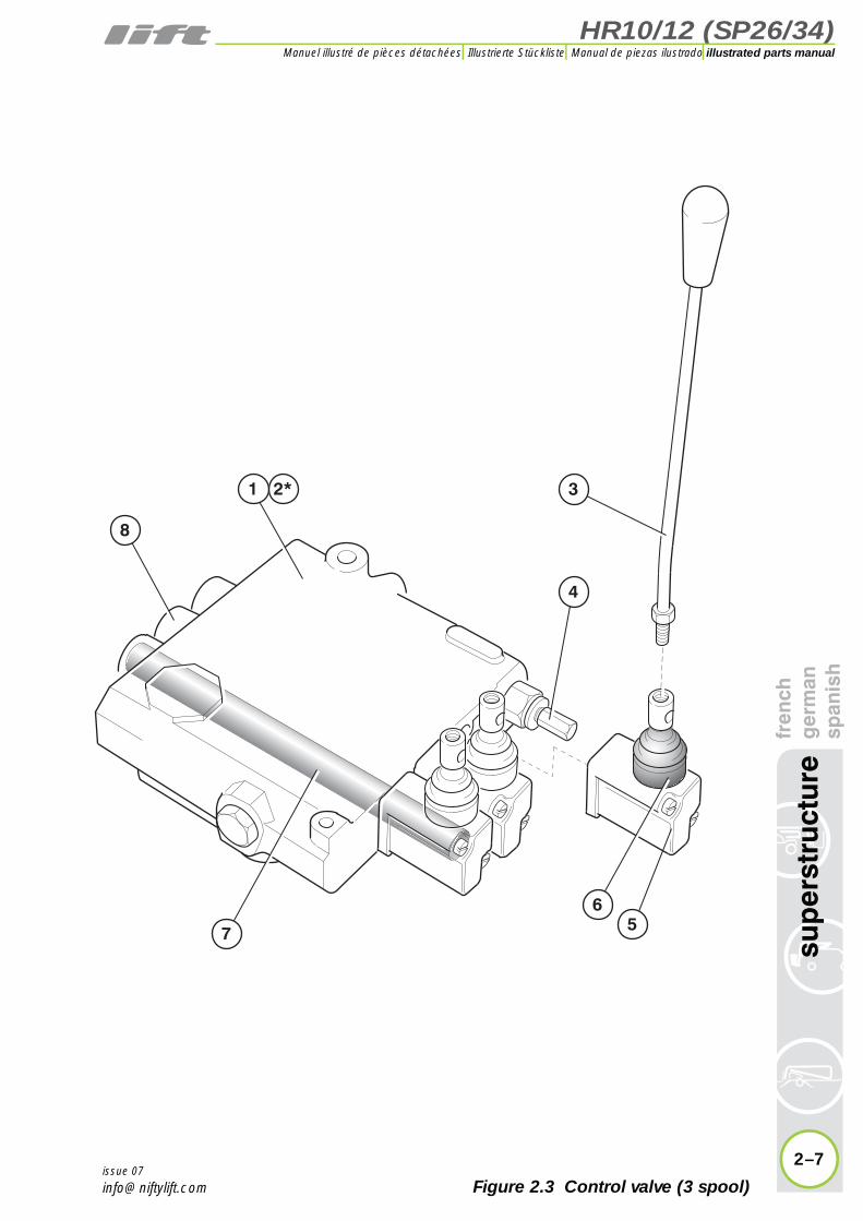
2.3 Control valve assembly (3 spool)Item Description Part Number
1
Control valve -
Gravity descent or double actingcylinders
Non-gravity descent or single actingcylinders
P15514
P15515
Seal kit for item 1 P70337
3 Lever P70336
4 Pressure relief valve P70335
5 Lever cap(complete) P70338
6 Rubber boot P12225
7Spool AS
ASTP15510P15511
8 Spool return spring assembly P16234
2 *
2–6
sup
erst
ruct
ure
fren
chg
erm
ansp
anis
h
issue 07
* Not illustrated
HR10/12 (SP26/34)
fren
chg
erm
ansp
anis
hsu
per
stru
ctur
e
2–7
illustrated parts manualManuel illustré de pièces détachées Illustrierte Stückliste Manual de piezas ilustrado
issue 07
1 3
56
7
4
2*
8
Figure 2.3 Control valve (3 spool)

HR10/12 (SP26/34)illustrated parts manual Manuel illustré de pièces détachées Illustrierte Stückliste Manual de piezas ilustrado
2.4 Control valve assembly (4 spool)Item Description Part Number
1 Control valve P15518
Seal kit for item 1 P70337
3 Lever P70336
4 Pressure relief valve P70335
5 Lever cap(complete) P70338
6 Rubber boot P12225
7Spool AS
ASTP15510P15511
8 Spool return spring assembly P16234
2 *
2–8
sup
erst
ruct
ure
fren
chg
erm
ansp
anis
h
issue 07
* Not illustrated

HR10/12 (SP26/34)
fren
chg
erm
ansp
anis
hsu
per
stru
ctur
e
2–9
illustrated parts manualManuel illustré de pièces détachées Illustrierte Stückliste Manual de piezas ilustrado
issue 07
1
3
56
7
4
2
8
Figure 2.4 Control valve (4 spool)

HR10/12 (SP26/34)illustrated parts manual Manuel illustré de pièces détachées Illustrierte Stückliste Manual de piezas ilustrado
renc
her
man
pan
ish
2.5 Button box assemblyItem Description Part Number
1E-Stop button
USA OnlyP10342P21541
2
(A) Pilot light lens(B) Bulb(C) Lamp holder(D) Lamp housing
P11295P11791P11790P14276
3Green button
(A) Rubber coverP10075P22414
4
Key switch - 455 key
key locked in lower and upper position
key removable in all positions
P10081
P10281
5 Button box - 4 hole P22417
6 Button box - 3 hole P22413
7Contact - NC(Used with item 1)
P11839
8Contact - NO(Used with item 3)
P11838
9 Key P70187
10Contact - Double NO(Used with item 4)
P11840
2–10
sup
erst
ruct
ure
f g s
issue 07

HR10/12 (SP26/34)
fren
chg
erm
ansp
anis
hsu
per
stru
ctur
e
2–11
illustrated parts manualManuel illustré de pièces détachées Illustrierte Stückliste Manual de piezas ilustrado
issue 07
6
5
1
3
4
1
2
3
4A
7
98
1
2
A
B
C
D
3
4
10
Figure 2.5 Button box

HR10/12 (SP26/34)illustrated parts manual Manuel illustré de pièces détachées Illustrierte Stückliste Manual de piezas ilustrado
ctur
efr
ench
ger
man
span
ish
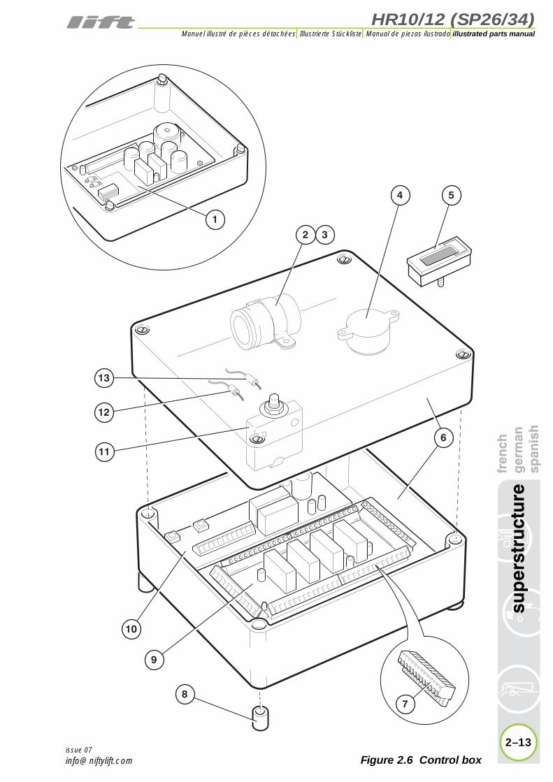
2.6 Control boxItem Description Part Number
Complete assembly12 v24 v
USA/Aus ElectricDiesel/Bi-energy
P17135P17137
P16444P16440
1 PCB - Pump(24 v ONLY) P14300
2 Capacitor(12 v ONLY) P15528
3 Clip P15529
4 Sounder(12v ONLY) P11112
5 Hour meter(OPTIONAL) P11410
6 ABS box P20368
7 Plug - 13-way P12945
8 Nylon spacer P11863
9PCB - 12 v
24 v
P11175
P14297
10PCB (Batterymanagement) - 12 v
- 24 v
P11174P14298
11 Circuit breaker - 10 A P11719
12 Diode P11179
13 Resistor(12 v ONLY) P11178
2–12
sup
erst
ru
issue 07
HR10/12 (SP26/34)
fren
chg
erm
ansp
anis
hsu
per
stru
ctur
e
2–13
illustrated parts manualManuel illustré de pièces détachées Illustrierte Stückliste Manual de piezas ilustrado
issue 07
12 3
87
9
11
12
13
10
6
4 5
Figure 2.6 Control box
HR10/12 (SP26/34)illustrated parts manual Manuel illustré de pièces détachées Illustrierte Stückliste Manual de piezas ilustrado
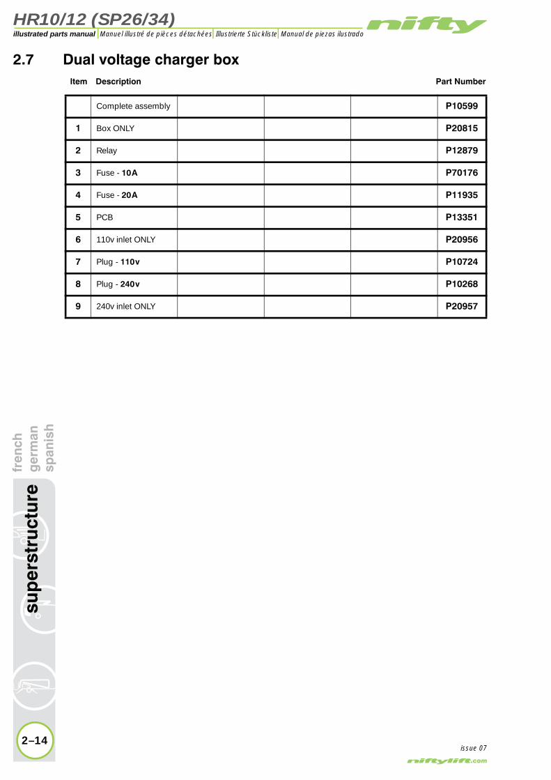
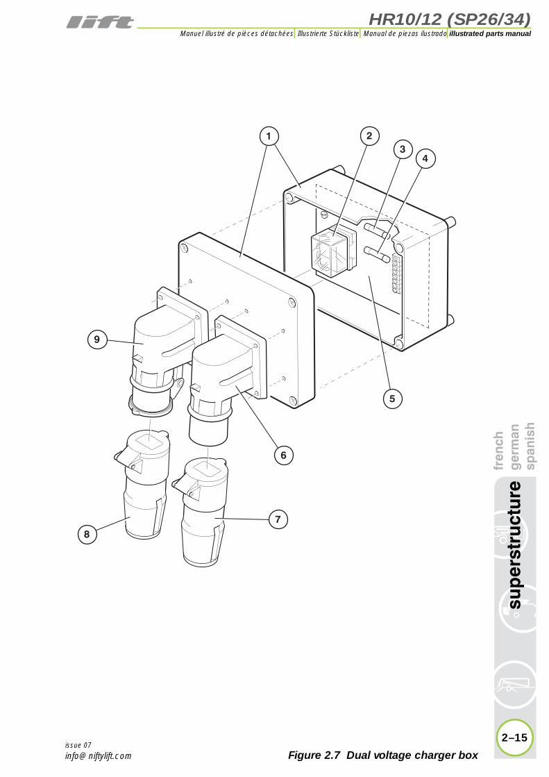
2.7 Dual voltage charger boxItem Description Part Number
Complete assembly P10599
1 Box ONLY P20815
2 Relay P12879
3 Fuse - 10 A P70176
4 Fuse - 20 A P11935
5 PCB P13351
6 110v inlet ONLY P20956
7 Plug - 110 v P10724
8 Plug - 240 v P10268
9 240v inlet ONLY P20957
2–14
sup
erst
ruct
ure
fren
chg
erm
ansp
anis
h
issue 07
HR10/12 (SP26/34)
fren
chg
erm
ansp
anis
hsu
per
stru
ctur
e
2–15
illustrated parts manualManuel illustré de pièces détachées Illustrierte Stückliste Manual de piezas ilustrado
issue 07
23
6
7
4
1
5
8
9
Figure 2.7 Dual voltage charger box

HR10/12 (SP26/34)illustrated parts manual Manuel illustré de pièces détachées Illustrierte Stückliste Manual de piezas ilustrado
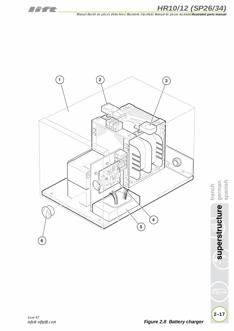
2.8 Battery chargerItem Description Part Number
1Charger assy UK
USAEuropean
P12759P11751P11067
2 Thermal cut-out - 110 v (UK only) P15268
3 Thermal cut-out - 240 v (Euro only) P15269
4 PCB P11371
5 Thyristor module P14993
6 Lens P11104
2–16
sup
erst
ruct
ure
fren
chg
erm
ansp
anis
h
issue 07
HR10/12 (SP26/34)
fren
chg
erm
ansp
anis
hsu
per
stru
ctur
e
2–17
illustrated parts manualManuel illustré de pièces détachées Illustrierte Stückliste Manual de piezas ilustrado
issue 07
3
4
5
6
21
Figure 2.8 Battery charger


HR10/12 (SP26/34)
3
illustrated parts manualManuel illustré de pièces détachéesIllustrierte StücklisteManual de piezas ilustrado
boom assembliesfrench
germanspanish
HR10/12 (SP26/34)illustrated parts manual Manuel illustré de pièces détachées Illustrierte Stückliste Manual de piezas ilustrado
3–2
bo
om
ass
emb
lies
fren
chg
erm
ansp
anis
h
issue 07
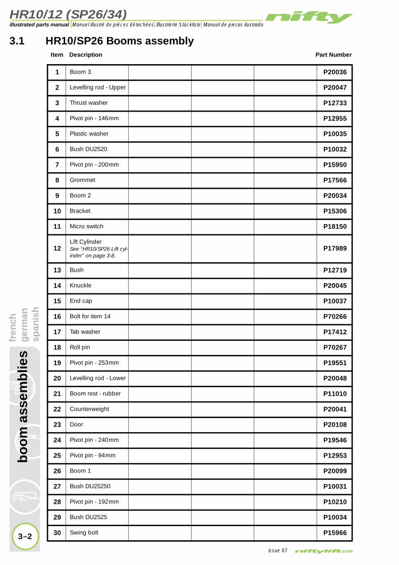
3.1 HR10/SP26 Booms assemblyItem Description Part Number
1 Boom 3 P20036
2 Levelling rod - Upper P20047
3 Thrust washer P12733
4 Pivot pin - 146 mm P12955
5 Plastic washer P10035
6 Bush DU2520 P10032
7 Pivot pin - 200 mm P15950
8 Grommet P17566
9 Boom 2 P20034
10 Bracket P15306
11 Micro switch P18150
12Lift CylinderSee “HR10/SP26 Lift cyl-inder” on page 3-8.
P17989
13 Bush P12719
14 Knuckle P20045
15 End cap P10037
16 Bolt for item 14 P70266
17 Tab washer P17412
18 Roll pin P70267
19 Pivot pin - 253 mm P19551
20 Levelling rod - Lower P20048
21 Boom rest - rubber P11010
22 Counterweight P20041
23 Door P20108
24 Pivot pin - 240 mm P19546
25 Pivot pin - 94 mm P12953
26 Boom 1 P20099
27 Bush DU25250 P10031
28 Pivot pin - 192 mm P10210
29 Bush DU2525 P10034
30 Swing bolt P15966

HR10/12 (SP26/34)
fren
chg
erm
ansp
anis
hb
oo
m a
ssem
blie
s
3–3
illustrated parts manualManuel illustré de pièces détachées Illustrierte Stückliste Manual de piezas ilustrado
issue 07
1
98
23
2524 24
34
20
11
6
275
4
13
7
1011
2829
5
6
5
2
12
5
22
21
14
195
6
28
6
13
3
1718
1516
26
30
Figure 3.1 HR10/SP26 Booms assembly

HR10/12 (SP26/34)illustrated parts manual Manuel illustré de pièces détachées Illustrierte Stückliste Manual de piezas ilustrado
bo
om
ass
emb
lies
fren
chg
erm
ansp
anis
h3.2 HR12/SP34 Booms assembly
Item Description Part Number
1 Boom 3 P22611
2 Nylatron washer P12733
3 Trunking P20167
4 Lid - Trunking P20168
5 Pivot pin - 127mm(Tele-cylinder) P12952
6 Bracket (Trunking to tracking) P12643
7 Washer guide P18771
8 Bracket - Roller P20169
9 Pin - Roller P10682
10 Roller P10680
11 Pivot pin - 85 mm P19550
12Levelling cylinderSee “Levelling cylin-der” on page 3-12.
P11764
13Pivot pin - 146mmRoll Pin
P12955P17485
14Lift cylinderSee “HR12/SP34 Lift cylinder” on page 3-10.
P11256
15 Grommet P11283
16 Boom 2 P20033
17 Bracket P20563
18 Micro switch P18150
19 Flanged bush P12719
20 Knuckle P20044
21 End cap P10037
22 Bolt for item 21 P70266
23 Tab washer P17412
24 Roll pin P70267
25 Plastic washer P10035
26 Bush DU2520 P10032
27 Pivot pin - 253 mm P19551
28 Levelling rod P20048
3–4issue 07

HR10/12 (SP26/34)
fren
chg
erm
ansp
anis
hb
oo
m a
ssem
blie
s
3–5
illustrated parts manualManuel illustré de pièces détachées Illustrierte Stückliste Manual de piezas ilustrado
issue 07
1615
10
1
4
7
31
3339 3238 324149
51
52
50
28
35
4748
2625
3724
36
19
17
5
6
18
3
2
54
19
4546
30
14
29
20
2725
26
12118
910
1053
13
2
23
24
2122
34
55
42
40
4344
Figure 3.2 HR12/SP34 Booms assembly

HR10/12 (SP26/34)illustrated parts manual Manuel illustré de pièces détachées Illustrierte Stückliste Manual de piezas ilustrado
bo
om
ass
emb
lies
fren
chg
erm
ansp
anis
h3.2 continued
Item Description Part Number
29 Boom rest - rubber P11010
30Counterweight Wide
NarrowP20042P20040
31 Door P20108
32 Pivot pin - 240 mm P19546
33 Pivot pin - 94mm P12953
34 Boom 1 P20099
35Lift cylinderSee “HR12/SP34 Lift cyl-inder” on page 3-10.
P11255
36 Pivot pin - 200 mm P15950
37 Bush DU2550 P10031
38 Boom 4 P10423
39 Bush DU2525 P10034
40 Grommet P17566
41Levelling cylinderSee “Levelling cylin-der” on page 3-12.
P22974
42 Pivot pin - 95mm P12899
43 Hose hoop P11118
44 Wear pad P15899
45 Wear pad (Black) P22653
46Nylatron studNut
P11436P16312
47 Spacer P10601
48 Wear pad (Red) P10519
49 Upper bracket - Inner P19230
50 Upper bracket - Outer P19229
51 Lower bracket - Inner P19228
52 Lower bracket - Outer P19227
53Hose tracking assySee “Energy chain” on page 3-16.
P19226
54 Bracket (Trunking to Boom 4) P19915
55 Swing bolt P15966
3–6issue 07

HR10/12 (SP26/34)
fren
chg
erm
ansp
anis
hb
oo
m a
ssem
blie
s
3–7
illustrated parts manualManuel illustré de pièces détachées Illustrierte Stückliste Manual de piezas ilustrado
issue 07
1615
10
1
4
7
31
3339 3238 324149
51
52
50
28
35
4748
2625
3724
36
19
17
5
6
18
3
2
54
19
4546
30
14
29
20
2725
26
12118
910
1053
13
2
23
24
2122
34
55
42
40
4344
Figure 3.2 HR12/SP34 Booms assembly
HR10/12 (SP26/34)illustrated parts manual Manuel illustré de pièces détachées Illustrierte Stückliste Manual de piezas ilustrado
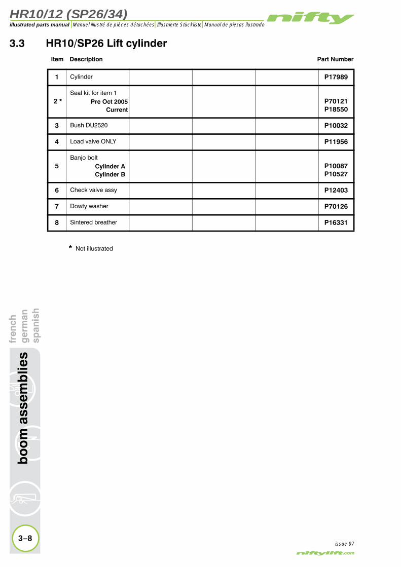
3.3 HR10/SP26 Lift cylinderItem Description Part Number
1 Cylinder P17989
Seal kit for item 1Pre Oct 2005
CurrentP70121P18550
3 Bush DU2520 P10032
4 Load valve ONLY P11956
5Banjo bolt
Cylinder ACylinder B
P10087P10527
6 Check valve assy P12403
7 Dowty washer P70126
8 Sintered breather P16331
2 *
3–8
bo
om
ass
emb
lies
fren
chg
erm
ansp
anis
h
issue 07
* Not illustrated

HR10/12 (SP26/34)
fren
chg
erm
ansp
anis
hb
oo
m a
ssem
blie
s
3–9
illustrated parts manualManuel illustré de pièces détachées Illustrierte Stückliste Manual de piezas ilustrado
issue 07
1
3
3
3
4
5
6
7
2*
CYLINDER A
CYLINDER B
8
Figure 3.3 HR10/SP26 Lift cylinder

HR10/12 (SP26/34)illustrated parts manual Manuel illustré de pièces détachées Illustrierte Stückliste Manual de piezas ilustrado
3.4 HR12/SP34 Lift cylinderItem Description Part Number
1Cylinder - A
BP11255P11256
Seal kit for item 1 P11369
3 Bush DU2520 P10032
4 Load valve ONLY P11956
5Banjo bolt -
Cylinder ACylinder B
P10267P10527
6 Check valve assy P12403
7 Dowty washer P70126
2 *
3–10
bo
om
ass
emb
lies
fren
chg
erm
ansp
anis
h
issue 07
* Not illustrated

HR10/12 (SP26/34)
fren
chg
erm
ansp
anis
hb
oo
m a
ssem
blie
s
3–11
illustrated parts manualManuel illustré de pièces détachées Illustrierte Stückliste Manual de piezas ilustrado
issue 07
1
3
3
3
4
5
6
7
2*
CYLINDER A
CYLINDER B
Figure 3.4 HR12/SP34 Lift cylinder
HR10/12 (SP26/34)illustrated parts manual Manuel illustré de pièces détachées Illustrierte Stückliste Manual de piezas ilustrado
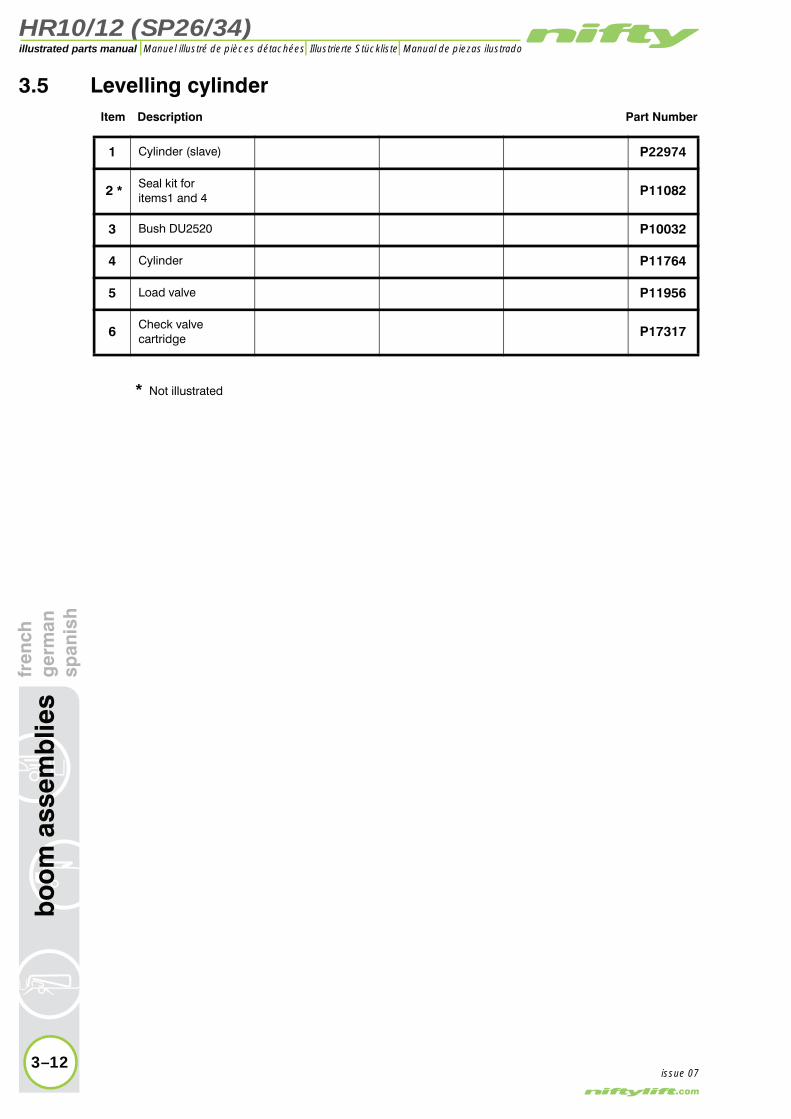
3.5 Levelling cylinderItem Description Part Number
1 Cylinder (slave) P22974
Seal kit foritems1 and 4 P11082
3 Bush DU2520 P10032
4 Cylinder P11764
5 Load valve P11956
6 Check valvecartridge P17317
2 *
3–12
bo
om
ass
emb
lies
fren
chg
erm
ansp
anis
h
issue 07
* Not illustrated

HR10/12 (SP26/34)
fren
chg
erm
ansp
anis
hb
oo
m a
ssem
blie
s
3–13
illustrated parts manualManuel illustré de pièces détachées Illustrierte Stückliste Manual de piezas ilustrado
issue 07
�
�
�
�
��
��
��
��
Figure 3.5 Levelling cylinder

HR10/12 (SP26/34)illustrated parts manual Manuel illustré de pièces détachées Illustrierte Stückliste Manual de piezas ilustrado
3.6 Telescope cylinderItem Description Part Number
1 Cylinder P13348
Seal kit for item 1 P11756
3 Bush DU2520 P10032
4 Check valvecartridge P17317
5Load valve(Fitted to machinesafter Jan 2004)
P11956
6 Bracket P10512
2 *
3–14
bo
om
ass
emb
lies
fren
chg
erm
ansp
anis
h
issue 07
* Not illustrated

HR10/12 (SP26/34)
fren
chg
erm
ansp
anis
hb
oo
m a
ssem
blie
s
3–15
illustrated parts manualManuel illustré de pièces détachées Illustrierte Stückliste Manual de piezas ilustrado
issue 07
6
1
54
4
3
2*
Figure 3.6 Telescope cylinder
HR10/12 (SP26/34)illustrated parts manual Manuel illustré de pièces détachées Illustrierte Stückliste Manual de piezas ilustrado
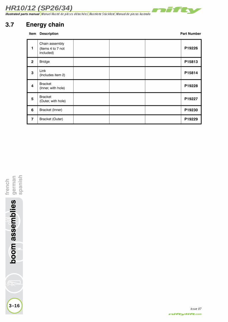
3.7 Energy chainItem Description Part Number
1Chain assembly(Items 4 to 7 not included)
P19226
2 Bridge P15813
3 Link(Includes item 2) P15814
4 Bracket(Inner, with hole) P19228
5 Bracket(Outer, with hole) P19227
6 Bracket (Inner) P19230
7 Bracket (Outer) P19229
3–16
bo
om
ass
emb
lies
fren
chg
erm
ansp
anis
h
issue 07

HR10/12 (SP26/34)
fren
chg
erm
ansp
anis
hb
oo
m a
ssem
blie
s
3–17
illustrated parts manualManuel illustré de pièces détachées Illustrierte Stückliste Manual de piezas ilustrado
issue 07
2
7
4
5
3
6
1
Figure 3.7 Energy chain


HR10/12 (SP26/34)
4
illustrated parts manualManuel illustré de pièces détachéesIllustrierte StücklisteManual de piezas ilustrado
cage assemblyfrench
germanspanish

HR10/12 (SP26/34)illustrated parts manual Manuel illustré de pièces détachées Illustrierte Stückliste Manual de piezas ilustrado
ssem
bly
fren
chg
erm
ansp
anis
h4.1 Cage assembly
Item Description Part Number
1
Cage HR10With cage weigh
Spring Load Cell
Non cage weigh
P18292P17052P10835
1
Cage HR12With cage weigh
Spring Load Cell
Non cage weigh
P20726P20495P10843
1
Cage - Central mounting HR12With cage weigh
Spring P23634
2 Bush P10840
3 Cage gate P11610
4 Bush P18647
5 Step (Cage P18292 ONLY) P16905
6 Cap P10841
7 Bracket - Beacon (OPTIONAL) P11451
8 Beacon (OPTIONAL) P10274
9 Guard - Beacon (OPTIONAL) P10312
10 Foot switch (OPTIONAL) P10759
11 Electrical contact P15209
4–2
cag
e a
issue 08
12 Instruction manual box (OPTIONAL) P11618
13 Hoop (U Bolt) P10566
14 Guard bar P20947

HR10/12 (SP26/34)
fren
chg
erm
ansp
anis
hca
ge
asse
mb
ly
4–3
illustrated parts manualManuel illustré de pièces détachées Illustrierte Stückliste Manual de piezas ilustrado
issue 08
1
6
1110
7 8
12
9
14
13
5
4
2
3
Figure 4.1 Cage assembly

HR10/12 (SP26/34)illustrated parts manual Manuel illustré de pièces détachées Illustrierte Stückliste Manual de piezas ilustrado
bly
fren
chg
erm
ansp
anis
h4.2 Cage weigh assembly - Spring (HR10)
1 Cage P18292
2 Pivot pin - 274 mm P17942
3 Washer P18058
4 Bearing P18080
5 Distance tube - 111 mm P17974
6 Distance tube - 183 mm P17975
7 Inner frame P18162
8 Spring P18079
9 Grommet P14456
10 Microswitch P18150
11 Outer frame P18273
12 Distance tube - 182 mm P17944
13 Swivel arm P17938
14 Pivot pin - 208 mm P17940
15 Pivot pin - 251 mm P17941
16 Pivot pin - 185 mm P10571
17 Pivot pin - 192 mm P10210
Item Description Part Number
4–4
cag
e as
sem
issue 08

HR10/12 (SP26/34)
fren
chg
erm
ansp
anis
hca
ge
asse
mb
ly
4–5
illustrated parts manualManuel illustré de pièces détachées Illustrierte Stückliste Manual de piezas ilustrado
issue 08
17
16
4
5 6
3
7
8
4
2
1
9
3
3
4
11
13
12
10
3
3
3
3
43
14
15
13
4
Figure 4.2 Cage weigh assembly - Spring (HR10)

HR10/12 (SP26/34)illustrated parts manual Manuel illustré de pièces détachées Illustrierte Stückliste Manual de piezas ilustrado
4.3 Cage weigh assembly - Load Cell (HR10)
1 Load cell P18179
2 Lower chassis P17056
3 Grommet P16983
4 Pin - 192 mm P10210
5 Pin - 145 mm P16799
6 Rubber grommet P14456
7PCB - 2000kg
12v24v
P18185P18531
8 Box assembly(Includes item 7) P17133
Item Description Part Number
4–6
cag
e as
sem
bly
fren
chg
erm
ansp
anis
h
issue 08

HR10/12 (SP26/34)
fren
chg
erm
ansp
anis
hca
ge
asse
mb
ly
4–7
illustrated parts manualManuel illustré de pièces détachées Illustrierte Stückliste Manual de piezas ilustrado
issue 08
8
7
2
1
4
5
3
3
6
Figure 4.3 Cage weigh assembly - Load cell (HR10)

HR10/12 (SP26/34)illustrated parts manual Manuel illustré de pièces détachées Illustrierte Stückliste Manual de piezas ilustrado
age
asse
mb
lyfr
ench
ger
man
span
ish
4.4 Cage weigh assembly - Spring (HR12)Item Description Part Number
1 CageRefer to
Figure 4.1
2 Pivot pin - 274mm P17942
3 Washer P18058
4 Grommet P14456
5 Bearing P18080
6 Distance tube - 183 mm P17975
7 Distance tube - 111 mm P17974
8 Inner frame P17937
9 Spring P18079
10 Pivot pin - 208mm P17940
11 Pivot pin - 251mm P17941
12 Swivel arm P17938
13 Distance tube - 182 mm P17944
14 Outer frame P17936
15 Microswitch P18150
16 Washer P10035
17 Pivot pin - 192mm P10210
18Levelling cylinderSee “Levelling cylin-der” on page 3-12.
P22974
19 Pivot pin - 182mm P10029
20 Pivot pin - 95mm P12899
4–8
c
issue 08

HR10/12 (SP26/34)
fren
chg
erm
ansp
anis
hca
ge
asse
mb
ly
4–9
illustrated parts manualManuel illustré de pièces détachées Illustrierte Stückliste Manual de piezas ilustrado
issue 08
1
3
5
3
3
7
8
15
9
5
3
14
12
3
2
4
3
10
11
13
5
18 17
16
16
5
6
12
20 19
Figure 4.4 Cage weigh assembly - Spring (HR12)

HR10/12 (SP26/34)illustrated parts manual Manuel illustré de pièces détachées Illustrierte Stückliste Manual de piezas ilustrado
4.5 Cage weigh assembly - Load Cell (HR12)
1 Pin - 95mm P12899
2Levelling cylinderSee “Levelling cylin-der” on page 3-12.
P22974
3 Grommet P14456
4 Load cell P18179
5 Rubber grommet P16983
6 Lower chassis P16866
7 Pin - 192mm P10210
8PCB - 2000kg
12v24v
P18185P18531
9 Box assembly(Includes item 8) P17133
Item Description Part Number
4–10
cag
e as
sem
bly
fren
chg
erm
ansp
anis
h
issue 08

HR10/12 (SP26/34)
fren
chg
erm
ansp
anis
hca
ge
asse
mb
ly
4–11
illustrated parts manualManuel illustré de pièces détachées Illustrierte Stückliste Manual de piezas ilustrado
issue 08
65
1
7
43
2
9
1
5
8
Figure 4.5 Cage weigh assembly - Load cell (HR12)
HR10/12 (SP26/34)illustrated parts manual Manuel illustré de pièces détachées Illustrierte Stückliste Manual de piezas ilustrado
4–12
cag
e as
sem
bly
fren
chg
erm
ansp
anis
h
issue 08
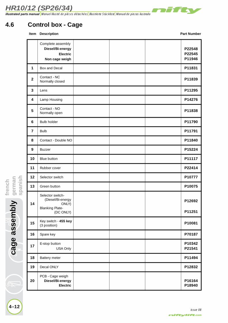
4.6 Control box - CageItem Description Part Number
Complete assemblyDiesel/Bi-energy
ElectricNon cage weigh
P22548P22545P11946
1 Box and Decal P11831
2 Contact - NCNormally closed P11839
3 Lens P11295
4 Lamp Housing P14276
5 Contact - NONormally open P11838
6 Bulb holder P11790
7 Bulb P11791
8 Contact - Double NO P11840
9 Buzzer P15224
10 Blue button P11117
11 Rubber cover P22414
12 Selector switch P10777
13 Green button P10075
14
Selector switch-(Diesel/Bi-energy
ONLY)Blanking Plate-
(DC ONLY)
P12692
P11251
15 Key switch - 455 key(3 position) P10081
16 Spare key P70187
17E-stop button
USA OnlyP10342P21541
18 Battery meter P11494
19 Decal ONLY P12832
20PCB - Cage weigh
Diesel/Bi-energyElectric
P16164P18940

HR10/12 (SP26/34)
fren
chg
erm
ansp
anis
hca
ge
asse
mb
ly
4–13
illustrated parts manualManuel illustré de pièces détachées Illustrierte Stückliste Manual de piezas ilustrado
issue 08
21
3 45
3
12
17
19
20
15
18
14
16
412
1311
67 8
585
58
910
11
Figure 4.6 Control box - Cage

HR10/12 (SP26/34)illustrated parts manual Manuel illustré de pièces détachées Illustrierte Stückliste Manual de piezas ilustrado
ench
erm
anp
anis
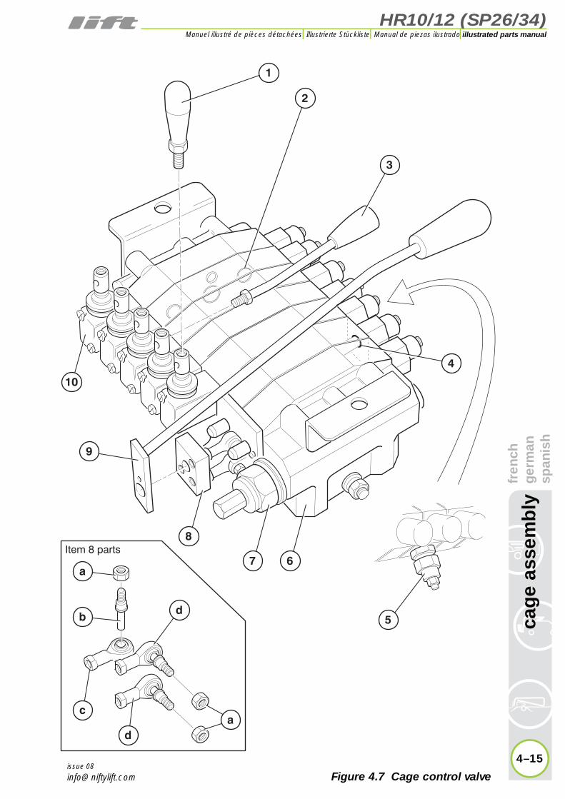
h4.7 Control valve - Cage
Item Description Part Number
1 Lever - levelling P70347
2 Interface seal kit P10706
3 Lever - 150mm P70346
4 Seal kit - Spool P10707
5Pressure relief valve
Telescope spoolLevelling spool
P10879P15840
6Control valve assy -
HR10/SP26 (5 spool)HR12/SP34 (7 spool)
P15516P15522
7 Pressure relief valve P70335
8
Manipulator assy. (complete)
a) Nutb) Vertical pinc) Universal jointd) UJ joint & pin
P10708
P12748P12749P12750P19917
9 Joystick P10310
10 Lever cap P70338
4–14
cag
e as
sem
bly
fr g s
issue 08
HR10/12 (SP26/34)
fren
chg
erm
ansp
anis
hca
ge
asse
mb
ly
4–15
illustrated parts manualManuel illustré de pièces détachées Illustrierte Stückliste Manual de piezas ilustrado
issue 08
1
4
3
5
67
8
ca
b
d
d
a
Item 8 parts
9
10
2
Figure 4.7 Cage control valve


HR10/12 (SP26/34)
5
illustrated parts manualManuel illustré de pièces détachéesIllustrierte StücklisteManual de piezas ilustrado
labellingfrench
germanspanish
HR10/12 (SP26/34)illustrated parts manual Manuel illustré de pièces détachées Illustrierte Stückliste Manual de piezas ilustrado
lab
ellin
gfr
ench
ger
man
span
ish
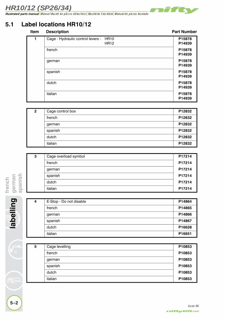
5.1 Label locations HR10/12Item Description Part Number
1 Cage - Hydraulic control levers - HR10HR12
P15878P14939
french P15878P14939
german P15878P14939
spanish P15878P14939
dutch P15878P14939
italian P15878P14939
2 Cage control box P12832
french P12832
german P12832
spanish P12832
dutch P12832
italian P12832
3 Cage overload symbol P17214
french P17214
german P17214
spanish P17214
dutch P17214
italian P17214
4 E-Stop - Do not disable P14864
french P14865
german P14866
spanish P14867
dutch P16628
italian P16651
5 Cage levelling P10853
french P10853
german P10853
spanish P10853
dutch P10853
italian P10853
5–2issue 06

HR10/12 (SP26/34)
fren
chg
erm
ansp
anis
hla
bel
ling
5–3
illustrated parts manualManuel illustré de pièces détachées Illustrierte Stückliste Manual de piezas ilustrado
issue 06
32
1
11
14
18
16
19
20
23
25
27 28
26
22 18
24
342928
9
8
7
17
8
15
4 5 6
10
9
11
12
33
29
3031
32
21
4
3635
374
39
4029
38
13
10
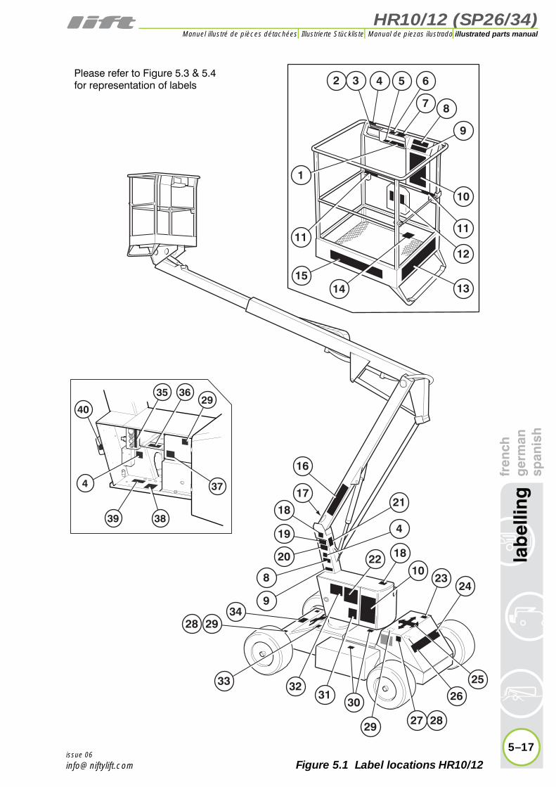
Please refer to Figure 5.3 & 5.4for representation of labels
Figure 5.1 Label locations HR10/12
HR10/12 (SP26/34)illustrated parts manual Manuel illustré de pièces détachées Illustrierte Stückliste Manual de piezas ilustrado
5–4
lab
ellin
gfr
ench
ger
man
span
ish
issue 06
5.1 continuedItem Description Part Number
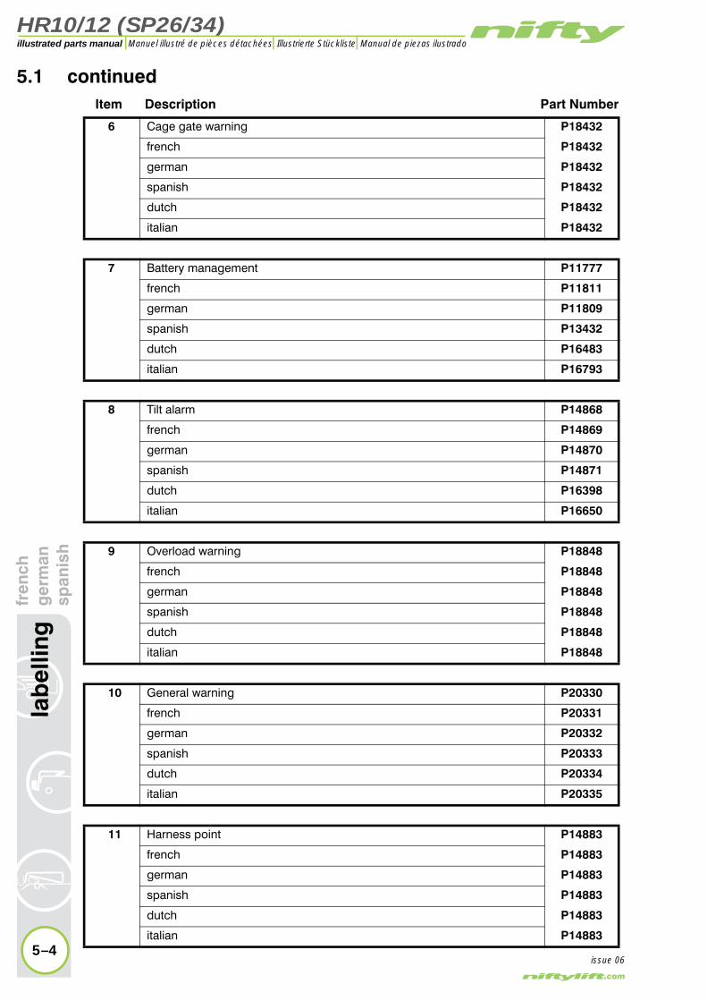
6 Cage gate warning P18432
french P18432
german P18432
spanish P18432
dutch P18432
italian P18432
7 Battery management P11777
french P11811
german P11809
spanish P13432
dutch P16483
italian P16793
8 Tilt alarm P14868
french P14869
german P14870
spanish P14871
dutch P16398
italian P16650
9 Overload warning P18848
french P18848
german P18848
spanish P18848
dutch P18848
italian P18848
10 General warning P20330
french P20331
german P20332
spanish P20333
dutch P20334
italian P20335
11 Harness point P14883
french P14883
german P14883
spanish P14883
dutch P14883
italian P14883

HR10/12 (SP26/34)
fren
chg
erm
ansp
anis
hla
bel
ling
5–5
illustrated parts manualManuel illustré de pièces détachées Illustrierte Stückliste Manual de piezas ilustrado
issue 06
32
1
11
14
18
16
19
20
23
25
27 28
26
22 18
24
342928
9
8
7
17
8
15
4 5 6
10
9
11
12
33
29
3031
32
21
4
3635
374
39
4029
38
13
10
Please refer to Figure 5.3 & 5.4for representation of labels
Figure 5.1 Label locations HR10/12

HR10/12 (SP26/34)illustrated parts manual Manuel illustré de pièces détachées Illustrierte Stückliste Manual de piezas ilustrado
lab
ellin
gfr
ench
ger
man
span
ish
5.1 continuedItem Description Part Number
12 Operating instructions P14892
french P14892
german P14892
spanish P14892
dutch P14892
italian P16639
13 Warning - SWL 200kg P14801
french P14801
german P14801
spanish P14801
dutch P16268
italian P16660
14 Footswitch P14884
french P14885
german P14886
spanish P14887
dutch P16898
italian P16656
15 niftylift.com P14390
french P14390
german P14390
spanish P14390
dutch P14390
italian P14390
16 Logo Nifty HR10 - GreyNifty HR12 - Grey
P14601P14604
frenchP14601P14604
germanP14601P14604
spanishP14601P14604
dutchP14601P14604
italianP14601P14604
5–6issue 06

HR10/12 (SP26/34)
fren
chg
erm
ansp
anis
hla
bel
ling
5–7
illustrated parts manualManuel illustré de pièces détachées Illustrierte Stückliste Manual de piezas ilustrado
issue 06
32
1
11
14
18
16
19
20
23
25
27 28
26
22 18
24
342928
9
8
7
17
8
15
4 5 6
10
9
11
12
33
29
3031
32
21
4
3635
374
39
4029
38
13
10
Please refer to Figure 5.3 & 5.4for representation of labels
Figure 5.1 Label locations HR10/12
HR10/12 (SP26/34)illustrated parts manual Manuel illustré de pièces détachées Illustrierte Stückliste Manual de piezas ilustrado
5–8
lab
ellin
gfr
ench
ger
man
span
ish
5.1 continuedItem Description Part Number
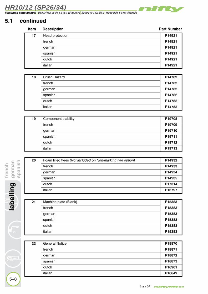
17 Head protection P14921
french P14921
german P14921
spanish P14921
dutch P14921
italian P14921
18 Crush Hazard P14782
french P14782
german P14782
spanish P14782
dutch P14782
italian P14782
19 Component stability P19708
french P19709
german P19710
spanish P19711
dutch P19712
italian P19713
20 Foam filled tyres (Not included on Non-marking tyre option) P14932
french P14933
german P14934
spanish P14935
dutch P17314
italian P16797
21 Machine plate (Blank) P15383
french P15383
german P15383
spanish P15383
dutch P15383
italian P15383
22 General Notice P18870
french P18871
german P18872
spanish P18873
dutch P16901
italian P16649
issue 06

HR10/12 (SP26/34)
fren
chg
erm
ansp
anis
hla
bel
ling
5–9
illustrated parts manualManuel illustré de pièces détachées Illustrierte Stückliste Manual de piezas ilustrado
issue 06
32
1
11
14
18
16
19
20
23
25
27 28
26
22 18
24
342928
9
8
7
17
8
15
4 5 6
10
9
11
12
33
29
3031
32
21
4
3635
374
39
4029
38
13
10
Please refer to Figure 5.3 & 5.4for representation of labels
Figure 5.1 Label locations HR10/12

HR10/12 (SP26/34)illustrated parts manual Manuel illustré de pièces détachées Illustrierte Stückliste Manual de piezas ilustrado
5–10
lab
ellin
gfr
ench
ger
man
span
ish
5.1 continuedItem Description Part Number
23 Noise warning P17124
french P17124
german P17124
spanish P17124
dutch P17124
italian P17124
24 Heightrider logo - HR10HR12
P14603P14605
french P14603P14605
german P14603P14605
spanish P14603P14605
dutchP14603P14605
italianP14603P14605
25 Travel direction P14784
french P14784
german P14784
spanish P14784
dutch P14784
italian P14784
26 Diesel fuel P14414
french P14414
german P14414
spanish P14414
dutch P14414
italian P14414
27 Point load (HR10 D/E/DE) -13.6kN(HR10 NDE) - 13.9 kN
P20606P14969
french P20606P14969
german P20606P14969
spanish P20606P14969
dutchP20606P14969
italianP20606P14969
issue 06

HR10/12 (SP26/34)
fren
chg
erm
ansp
anis
hla
bel
ling
5–11
illustrated parts manualManuel illustré de pièces détachées Illustrierte Stückliste Manual de piezas ilustrado
issue 06
32
1
11
14
18
16
19
20
23
25
27 28
26
22 18
24
342928
9
8
7
17
8
15
4 5 6
10
9
11
12
33
29
3031
32
21
4
3635
374
39
4029
38
13
10
Please refer to Figure 5.3 & 5.4for representation of labels
Figure 5.1 Label locations HR10/12
HR10/12 (SP26/34)illustrated parts manual Manuel illustré de pièces détachées Illustrierte Stückliste Manual de piezas ilustrado
lab
ellin
gfr
ench
ger
man
span
ish
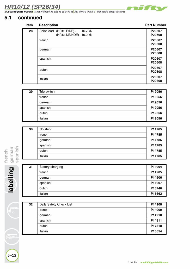
5.1 continuedItem Description Part Number
28 Point load (HR12 E/DE) - 16.7 kN(HR12 NE/NDE) - 19.2 kN
P20607P20608
french P20607P20608
german P20607P20608
spanish P20607P20608
dutchP20607P20608
italianP20607P20608
29 Trip switch P19056
french P19056
german P19056
spanish P19056
dutch P19056
italian P19056
30 No step P14785
french P14785
german P14785
spanish P14785
dutch P14785
italian P14785
31 Battery charging P14904
french P14905
german P14906
spanish P14907
dutch P16746
italian P16662
32 Daily Safety Check List P14908
french P14909
german P14910
spanish P14911
dutch P17318
italian P16654
5–12issue 06

HR10/12 (SP26/34)
fren
chg
erm
ansp
anis
hla
bel
ling
5–13
illustrated parts manualManuel illustré de pièces détachées Illustrierte Stückliste Manual de piezas ilustrado
issue 06
32
1
11
14
18
16
19
20
23
25
27 28
26
22 18
24
342928
9
8
7
17
8
15
4 5 6
10
9
11
12
33
29
3031
32
21
4
3635
374
39
4029
38
13
10
Please refer to Figure 5.3 & 5.4for representation of labels
Figure 5.1 Label locations HR10/12

HR10/12 (SP26/34)illustrated parts manual Manuel illustré de pièces détachées Illustrierte Stückliste Manual de piezas ilustrado
lab
ellin
gfr
ench
ger
man
span
ish
5.1 continuedItem Description Part Number
33 Battery isolator P18610
french P18610
german P18610
spanish P18610
dutch P18610
italian P18610
34 Drive wheel lock P19444
french P15570
german P15571
spanish P15572
dutch P16393
italian P16719
35 Base control cage weighnon cage weigh
P21055P21131
frenchP21055P21131
germanP21055P21131
spanishP21055P21131
dutchP21055P21131
italianP21055P21131
36 Base - Hydraulic control levers P14936
french (HR10)(HR12)
P14936P14937
german P14936
spanish P14936
dutch P14936
italian P14936
37 Base/Cage selector valve P19445
french P14071
german P14068
spanish P19445
dutch P16400
italian P16794
5–14issue 06

HR10/12 (SP26/34)
fren
chg
erm
ansp
anis
hla
bel
ling
5–15
illustrated parts manualManuel illustré de pièces détachées Illustrierte Stückliste Manual de piezas ilustrado
issue 06
32
1
11
14
18
16
19
20
23
25
27 28
26
22 18
24
342928
9
8
7
17
8
15
4 5 6
10
9
11
12
33
29
3031
32
21
4
3635
374
39
4029
38
13
10
Please refer to Figure 5.3 & 5.4for representation of labels
Figure 5.1 Label locations HR10/12

HR10/12 (SP26/34)illustrated parts manual Manuel illustré de pièces détachées Illustrierte Stückliste Manual de piezas ilustrado
fren
chg
erm
ansp
anis
h5.1 continued
Item Description Part Number
38 Manual descent P19716
french P19716
german P19716
spanish P19716
dutch P19716
italian P19716
39 Booms/Brakes selector P19446
french P16666
german P16667
spanish P16668
dutch P16399
italian P16796
40 Power inlet 110v220v
P17719P17720
frenchP17719P17720
germanP17719P17720
spanishP17719P17720
dutchP17719P17720
italianP17719P17720
5–16
lab
ellin
g
issue 06
HR10/12 (SP26/34)
fren
chg
erm
ansp
anis
hla
bel
ling
5–17
illustrated parts manualManuel illustré de pièces détachées Illustrierte Stückliste Manual de piezas ilustrado
issue 06
32
1
11
14
18
16
19
20
23
25
27 28
26
22 18
24
342928
9
8
7
17
8
15
4 5 6
10
9
11
12
33
29
3031
32
21
4
3635
374
39
4029
38
13
10
Please refer to Figure 5.3 & 5.4for representation of labels
Figure 5.1 Label locations HR10/12

HR10/12 (SP26/34)illustrated parts manual Manuel illustré de pièces détachées Illustrierte Stückliste Manual de piezas ilustrado
5–18
lab
ellin
gfr
ench
ger
man
span
ish
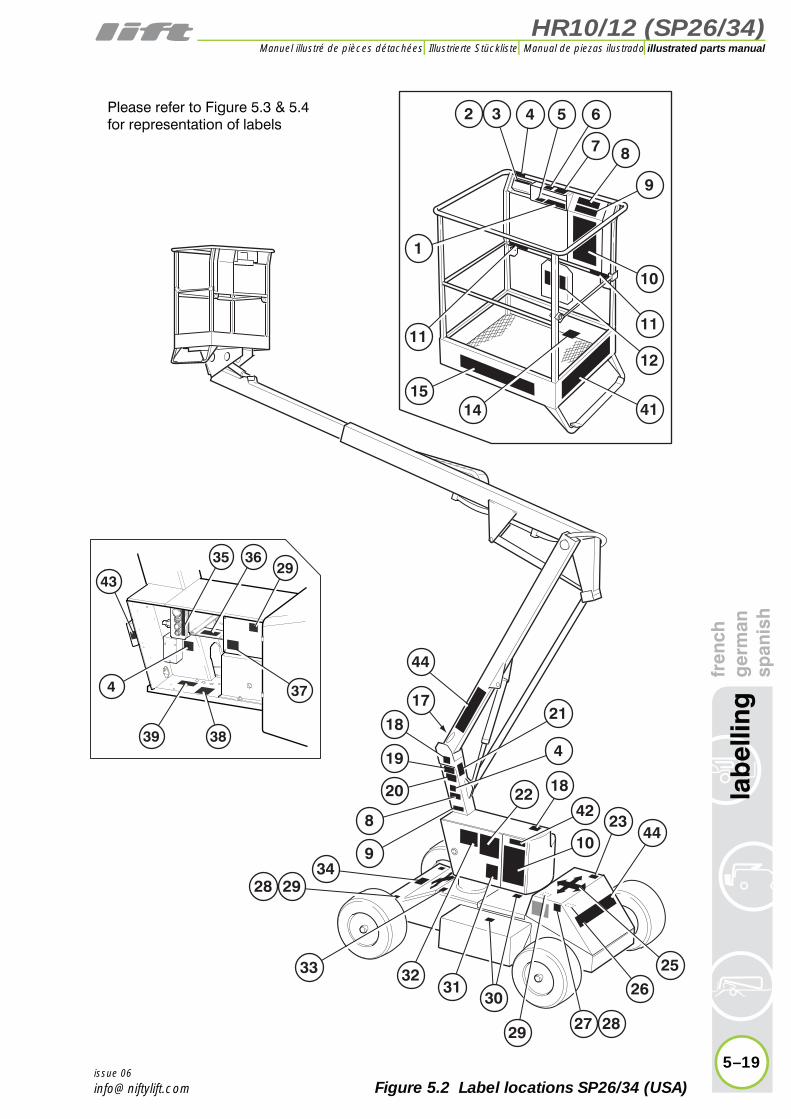
5.2 Label locations SP26/34 (USA)Item Description Part Number
1Cage - Hydraulic control levers - SP26
SP34P15878P14939
2 Cage control box P12832
3 Cage overload symbol P17214
4 E-Stop - Do not disable P14864
5 Cage levelling P10853
6 Cage gate warning P18432
7 Battery management P11777
8 Tilt alarm P14868
10 General warning P20330
11 Harness point P14883
12 Operating instructions P14892
14 Footswitch P14884
15 niftylift.com P14390
17 Head protection P14921
18 Crush hazard P14783
19 Component stability P19708
20 Foam filled tyres P14932
21 Identification plate (Blank) P15383
22 General Notice P18870
23 Noise warning P17124
25 Travel direction P14784
26 Diesel fuel P14414
27 Point load (SP26 D/E/DE) - 13.6 kN(SP26 NDE) - 13.9 kN
P20606P14969
28 Point load (SP34 E/DE) - 16.7 kN(SP34 NE/NDE) - 19.2 kN
P20607P20608
29 Trip switch P19056
30 No step P14785
31 Battery charging P14904
32 Daily safety check list P14908
33 Battery isolator P18610
34 Drive wheel lock P19444
35 Base control P21131
36 Base - Hydraulic control levers P14936
37 Base/Cage selector valve P19445
38 Manual handpump P19716
39 Booms/Brakes selector P19446
41 Platform capacity - 500 lbs P17328
42 Rotating machinery P15010
43 Charger socket P19699
44 Logo - SP26SP34
P11597P11598
issue 06
HR10/12 (SP26/34)
fren
chg
erm
ansp
anis
hla
bel
ling
5–19
illustrated parts manualManuel illustré de pièces détachées Illustrierte Stückliste Manual de piezas ilustrado
issue 06
32
1
11
14
18
44
19
20
23
25
27 28
26
22 18
44
342928
9
8
7
17
8
15
4 5 6
10
9
11
12
33
29
3031
32
21
4
3635
374
39
4329
38
41
42
10
Please refer to Figure 5.3 & 5.4for representation of labels
Figure 5.2 Label locations SP26/34 (USA)
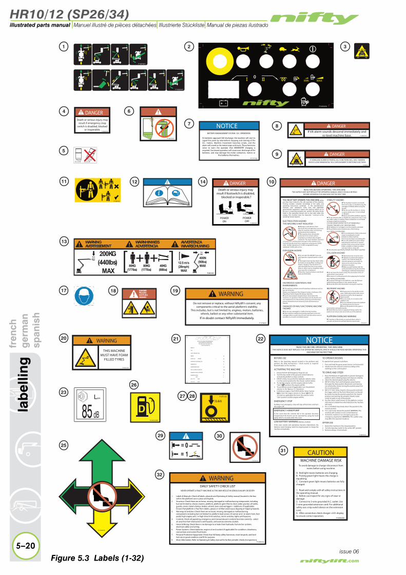
HR10/12 (SP26/34)
5–20
lab
ellin
gfr
ench
ger
man
span
ish
illustrated parts manual Manuel illustré de pièces détachées Illustrierte Stückliste Manual de piezas ilustrado
issue 06
Figure 5.3 Labels (1-32)
HR10/12 (SP26/34)
fren
chg
erm
ansp
anis
hla
bel
ling
5–21
illustrated parts manualManuel illustré de pièces détachées Illustrierte Stückliste Manual de piezas ilustrado
issue 06
Figure 5.4 Labels (33-43)


HR10/12 (SP26/34)
6
illustrated parts manualManuel illustré de pièces détachéesIllustrierte StücklisteManual de piezas ilustrado
hydraulic hosesfrench
germanspanish

HR10/12 (SP26/34)illustrated parts manual Manuel illustré de pièces détachées Illustrierte Stückliste Manual de piezas ilustrado
6–2
hyd
raul
ic h
ose
sfr
ench
ger
man
span
ish
issue 05
6.1 Hose kit HR10 (SP26)Ref Number Description french german spanish
1Base control to Ram 1 (Pressure)
2Base control to Ram 1 (Pilot)
3Base control to Ram 2 (Pressure)
4Base control to Ram 2 (Pilot)
5Cage control to Ram 1 (Pressure)
6Cage control to Ram 1 (Pilot)
7Cage control to Ram 2 (Pressure)
8Cage control to Ram 2 (Pilot)
9Base control to cage (slew pressure)
10Base control to cage (slew pilot)
11Cage control to steer ram left(Pressure)
12Cage control to steer ram left (Pilot)
13DCV to cage drive (Pressure)
14DCV to cage drive (Pilot)
15Diverter to cage (Pressure)
16 Cage return to DCV
17Base control to slew motor (Pressure)
18Base control to slew motor (Pilot)
20Handpump return to base control
23LH Power pack return to DCV
28 Base return to DCV
29Engine pump to Base control (Pressure)
32Base pressure to brake override
35Brake override to DCV

HR10/12 (SP26/34)
fren
chg
erm
ansp
anis
hh
ydra
ulic
ho
ses
6–3
illustrated parts manualManuel illustré de pièces détachées Illustrierte Stückliste Manual de piezas ilustrado
issue 05
1211
5455
52
53
1
2
3
1718
10
9
5
6
7
8
28
15
16
14 13
20
29
23
35
4
43
44
45
48
32
50
56
51
Cagecontrol
handpumpBasecontrol
steer ram
lift cylinder (1)
lift cylinder (2)
diverter
drive controlvalve(DCV)
LH power packpump
RH power packpump
engine pump
slew
RH steermotor
LH steermotor
P
P
P
P
T
T
TT
V1
V2
T
P2
P1
T
B
brake override
R
L
Figure 6.1 Hose connections (HR10/SP26)

HR10/12 (SP26/34)illustrated parts manual Manuel illustré de pièces détachées Illustrierte Stückliste Manual de piezas ilustrado
fren
chg
erm
ansp
anis
h6.1 continued
Ref Number Description french german spanish
43 *LH Power pack to engine pump(Pressure)
44 *RH Power pack to engine pump(Pressure)
45 *LH Power pack return to engine pump
48 *RH Power pack return to engine pump
50DCV (Brake) toLH steer motor
51DCV (Brake) toRH steer motor
52DCV to RH steer motor
53DCV to RH steer motor
54DCV to LH steer motor
55DCV to LH steer motor
56Handpump to brake override
* Bi-energy machines only
6–4
hyd
raul
ic h
ose
s
issue 05

HR10/12 (SP26/34)
fren
chg
erm
ansp
anis
hh
ydra
ulic
ho
ses
6–5
illustrated parts manualManuel illustré de pièces détachées Illustrierte Stückliste Manual de piezas ilustrado
issue 05
1211
5455
52
53
1
2
3
1718
10
9
5
6
7
8
28
15
16
14 13
20
29
23
35
4
43
44
45
48
32
50
56
51
Cagecontrol
handpumpBasecontrol
steer ram
lift cylinder (1)
lift cylinder (2)
diverter
drive controlvalve(DCV)
LH power packpump
RH power packpump
engine pump
slew
RH steermotor
LH steermotor
P
P
P
P
T
T
TT
V1
V2
T
P2
P1
T
B
brake override
R
L
Figure 6.1 Hose connections (HR10/SP26)

HR10/12 (SP26/34)illustrated parts manual Manuel illustré de pièces détachées Illustrierte Stückliste Manual de piezas ilustrado
6–6
hyd
raul
ic h
ose
sfr
ench
ger
man
span
ish
6.2 Hose kit HR12 (SP34)Ref Number Description french german spanish
1Base control to Ram 1 (Pressure)
2Base control to Ram 1 (Pilot)
3Base control to Ram 2 (Pressure)
4Base control to Ram 2 (Pilot)
5Base slew to cage slew (Pressure)
6Base slew to cage slew (Pilot)
7Cage control to Ram 1 (Pressure)
8Cage control to Ram 1 (Pilot)
9Cage control to Ram 2 (Pressure)
10Cage control to Ram 2 (Pilot)
11Cage control to steer ram (Pressure)
12Cage control to steer ram (Pilot)
13Diverter valve to cage control(Pressure)
14Cage control to drive control valve
15Drive control valve to cage control (Pressure)
16Drive control valve to cage control (Pilot)
17Base control to slew (Pilot)
18Base control to slew (Pressure)
19Cage control to master levelling ram (Pressure)
20Cage control to master levelling ram (Pilot)
21Cage control to slave levelling ram (Pressure)
issue 05

HR10/12 (SP26/34)
fren
chg
erm
ansp
anis
hh
ydra
ulic
ho
ses
6–7
illustrated parts manualManuel illustré de pièces détachées Illustrierte Stückliste Manual de piezas ilustrado
issue 05
Cage control
handpumpBase control
steer ram
brake override
lift ram (1)
telescoping ram
cage levelling (slave)knuckle (master)
diverter
drive controlvalve(DCV)
LH power packpump
RH power packpump
slew
RH steermotor
LH steermotor
P
P
P
T
T
TT
LR
T
engine
P
T
P2
P1
lift ram(2)
B
11
12
54
55
52
53
56
32
1
2
3
1817
6
5
47
46
7
8
10
9
28
29
30
35
4
22
19
21 2324
20
4448
45 43
38
40
15
14
42
13
1650
51
Figure 6.2 Hose connections (HR12/SP34)
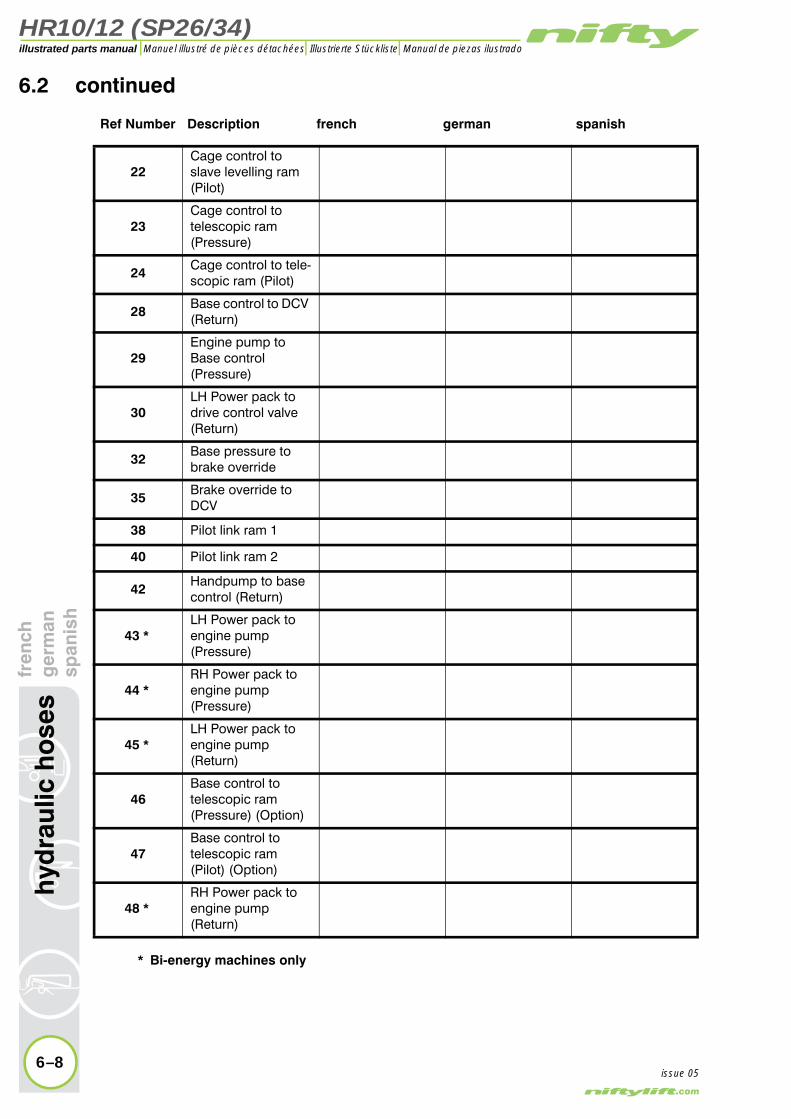
HR10/12 (SP26/34)illustrated parts manual Manuel illustré de pièces détachées Illustrierte Stückliste Manual de piezas ilustrado
hyd
raul
ic h
ose
sfr
ench
ger
man
span
ish
6.2 continued
Ref Number Description french german spanish
22Cage control to slave levelling ram (Pilot)
23Cage control totelescopic ram(Pressure)
24Cage control to tele-scopic ram (Pilot)
28Base control to DCV (Return)
29Engine pump to Base control(Pressure)
30LH Power pack to drive control valve (Return)
32Base pressure to brake override
35Brake override to DCV
38 Pilot link ram 1
40 Pilot link ram 2
42Handpump to base control (Return)
43 *LH Power pack to engine pump(Pressure)
44 *RH Power pack to engine pump(Pressure)
45 *LH Power pack to engine pump(Return)
46Base control totelescopic ram(Pressure) (Option)
47Base control totelescopic ram(Pilot) (Option)
48 *RH Power pack to engine pump(Return)
* Bi-energy machines only
6–8issue 05
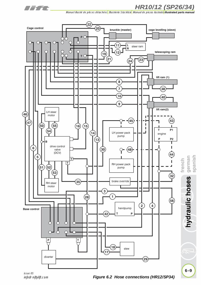
HR10/12 (SP26/34)
fren
chg
erm
ansp
anis
hh
ydra
ulic
ho
ses
6–9
illustrated parts manualManuel illustré de pièces détachées Illustrierte Stückliste Manual de piezas ilustrado
issue 05
Cage control
handpumpBase control
steer ram
brake override
lift ram (1)
telescoping ram
cage levelling (slave)knuckle (master)
diverter
drive controlvalve(DCV)
LH power packpump
RH power packpump
slew
RH steermotor
LH steermotor
P
P
P
T
T
TT
LR
T
engine
P
T
P2
P1
lift ram(2)
B
11
12
54
55
52
53
56
32
1
2
3
1817
6
5
47
46
7
8
10
9
28
29
30
35
4
22
19
21 2324
20
4448
45 43
38
40
15
14
42
13
1650
51
Figure 6.2 Hose connections (HR12/SP34)
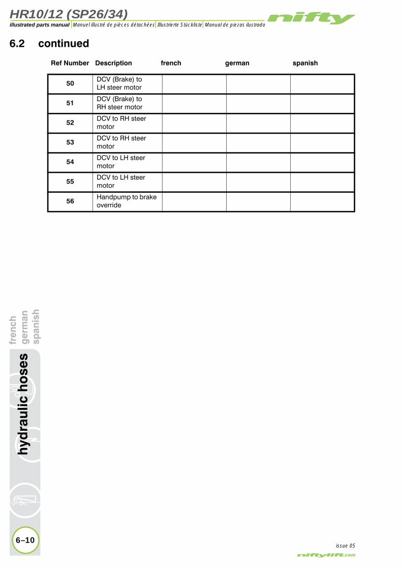
HR10/12 (SP26/34)illustrated parts manual Manuel illustré de pièces détachées Illustrierte Stückliste Manual de piezas ilustrado
6.2 continued
Ref Number Description french german spanish
50DCV (Brake) toLH steer motor
51DCV (Brake) toRH steer motor
52DCV to RH steer motor
53DCV to RH steer motor
54DCV to LH steer motor
55DCV to LH steer motor
56Handpump to brake override
6–10
hyd
raul
ic h
ose
sfr
ench
ger
man
span
ish
issue 05

HR10/12 (SP26/34)
fren
chg
erm
ansp
anis
hh
ydra
ulic
ho
ses
6–11
illustrated parts manualManuel illustré de pièces détachées Illustrierte Stückliste Manual de piezas ilustrado
issue 05
Cage control
handpumpBase control
steer ram
brake override
lift ram (1)
telescoping ram
cage levelling (slave)knuckle (master)
diverter
drive controlvalve(DCV)
LH power packpump
RH power packpump
slew
RH steermotor
LH steermotor
P
P
P
T
T
TT
LR
T
engine
P
T
P2
P1
lift ram(2)
B
11
12
54
55
52
53
56
32
1
2
3
1817
6
5
47
46
7
8
10
9
28
29
30
35
4
22
19
21 2324
20
4448
45 43
38
40
15
14
42
13
1650
51
Figure 6.2 Hose connections (HR12/SP34)
