hs-360 series technical manual - harmonic drive® high ... · dc servo driver hs-360 series...
TRANSCRIPT

DC Servo Driver
HS-360 Series Technical Manual
Thank you very much for your purchasing our HS-360 series servo driver.
Be sure to use sufficient safety measures when installing and operating the equipment so as to prevent an accident resulting in a serious physical injury damaged by a malfunction or improper operation.
Product specifications are subject to change without notice for improvement purposes.
Keep this manual in a convenient location and refer to it whenever necessary in operating or maintaining the units.
End user of the driver should have a copy of this manual.
ISO14001(HOTAKA Plant)ISO9001

Caution
HS Series Safety guide for handling servomotors
Warning:Indicates a potentially hazardous situation, which, if not avoided, could result in death or serious personal injury.
CAUTION : Indicates a potentially hazardous situation, which, if not avoided, may result in minor or moderate personal injury and/or damage to the
Precautions when using an Actuator
APPLICATION DESIGN: Read the technical manual before designing. Use it in designed conditions. The actuator must only be used indoors, where the following conditions areprovided: -Ambient temperature: 0°C to 40°C -Ambient humidity: 20% to 80%RH (Non-condensation) -Vibration: Max 24.5 m/S2 -No contamination by water, oil or foreign matters
Follow exactly the instructions for installation. Ensure exact alignment of motor shaft center and corresponding center in
the application. Failure to observe this caution may lead to vibration, resulting in damage of
the bearings.
OPEARTION DESIGN: Read technical manual before operatingDo not exceed the allowable torque. Avoid any torque over the maximum torque from being exerted. Be aware that if the arm hits the output shaft when coming into contact with it,
the output shaft may become uncontrollable, or the actuator may be damaged.
Warning
Never connect cables directly to the outlet or power supply. The actuator needs to be connected to the dedicated driver to operate. Never connect the actuator directly to the commercial power supply or
batteries, etc. The actuator may be damaged, resulting in fire.
Protect the actuator from impact and shocks. Do not use a hammer to position the actuator during installation. Failure to observe this caution could damage the encoder and may cause
uncontrollable operation.
Avoid handling of the actuator by its cables. Failure to observe this caution may damage the wiring, causing
uncontrollable or faulty operation.
Precautions when using a Driver
APPLICATION DESIGN: Read the technical manual before designing. Always use the driver in an environment where thefollowing conditions are provided. Keep sufficient distance to other devices to let the heat generated by the driver
radiate freely *Mount in a vertical position *Ambient temperature: 0°C to 50°C, humidity
: less than 95% RH (Non-condensations) *Protect the driver from impact or shock. *No corrosive, inflammable or explosive gas.
Provide sufficient noise suppression and safe grounding. Always keep signal wire away from noises to avoid vibration and malfunction.*Keep signal and power leads separated. *Keep leads as short as possible. *Ground actuator and driver at one single point, minimum ground resistance
class: D. *Do not use a power line filter in the motor circuit.
Caution
Be careful when turning from the load side. Be careful with turning the actuator from the output side as this may damage
the driver. Please consult our sales office, if you intent to use the product in such anapplication.
Caution
Use a fast-response type ground-fault detector designed for PWM inverters. Do not use a time-delay-type ground-fault detector.
Warning
OPEARTION DESIGN: Read technical manual before operatingNever change wiring while power is ON. Be sure to turn OFF power before servicing the product. Failure to observe this caution may result in electric shock or personal injury.
Warning
Do not touch the terminals right after turning off power.Otherwise residual electric charges may result in electric shock. Provide a housing for the control unit to avoid contact with electric parts.
Caution
Do not make a voltage resistance test. Failure to observe this caution may result in damage of the control unit. Please consult our sales office, if you intent to use in such an application.
Caution
Do not operate a control unit by means of power ON/OFF switching. Start/stop operation should be performed via input signals. Failure to observe this caution may result in deterioration of electronic parts.
Caution
Caution
Caution
Disposal of an actuator, a motor, a control unit or their parts
Caution
All products or parts have to be disposed of as industrial waste.
LIMITATION OF APPLICATIONS: This equipment may not be used for the following applications. *Space equipment *Aircraft, aeronautic equipment *Nuclear equipment *Amusement equipment, sport equipment, game machines *Vacuum equipment *
Automobile, automotive parts *Machine or devices acting directly on the human body *Instruments or devices to transport or carry people *Apparatus or devices
used in special environments *Explosion proof equipment Please consult us, if you intend to use our products in one of the areas mentioned above. Safety measures are essential to prevent accidents resulting in death, injury or damage of the equipment due to malfunction or
Caution
Caution
Caution

DC servo driver HS-360 Series
- Contents 1-
Contents Chapter 1 Outline of HS-360 driver······························································································ 1
1-1 Main features·················································································································· 1 1-2 Ordering information of HS-360 driver ·········································································· 2 1-3 Combination with actuator ····························································································· 2 1-4 Specification of HS-360 driver ······················································································· 3
1-5 External drawing of HS-360 driver ················································································ 4 1-6 Names and functions of front panel components ·························································· 5
Chapter 2 Connector pin layout··································································································· 7
2-1 TB1 power supply terminal pin layout ······································································· 7 2-1 TB2 actuator cable connection terminal pin layout ··················································· 7 2-3 CN1 external I/O connector pin layout······································································· 7 2-4 CN2 encoder and limit signal connector pin layout ··················································· 8 2-5 CN3serial port connector pin layout EIA232C-compliant (RS-232C)························· 9
Chapter 3 Control input/output ··································································································10 3-1 command pulse input (CN1)························································································10 3-2 Selecting the command pulse input configuration ······················································· 11
3-2-1 2-pulse train (FWD and REV pulse train)···································································· 11 3-2-2 1-pulse train (polarity + pulse train)············································································· 11 3-2-3 2-pulse train (2-phase pulses with 90-degree difference) ··········································· 11
3-3 Control Input Signals (CN1, CN2)················································································12 3-3-1 CN1 input signal connection and functions ·································································12 3-3-2 CN2 input signal connection and functions ·································································14
3-4 Control output Signals (CN1, CN2)··············································································15 3-4-1 CN1 input signal connection and functions ································································15
3-4-2 CN2 input signal connection and functions(encoder monitor output) ·························17 3-5 Encoder input (CN2)····································································································18 3-6 External connection examples ····················································································19
Chapter 4 Installing driver ··········································································································21
4-1 Receiving Inspection ··································································································21 4-2 Notices on handling drivers ························································································22 4-3 Location and installation ·····························································································23
4-3-1 Environment of location ······························································································23 4-3-2 Notices on installation·································································································23 4-3-3 Installing ······················································································································24
4-4 Suppressing noise ·······································································································24 4-4-1 Devices for grounding ·································································································24 4-4-2 Installing noise filters ···································································································25 4-4-3 Instructions for cabling ································································································26

DC servo driver HS-360 Series
- Contents 2-
4-5 Connecting power cables·····························································································27 4-5-1 Instructions for power supply ······················································································27 4-5-2 Power cables and ground wires··················································································27 4-5-3 Connecting power cables ···························································································28 4-5-4 Isolation transformer (sold optionally)·········································································28 4-5-5 Protecting the power line ····························································································29
4-6 Connecting the ground wire ························································································29 4-7 Connecting the actuator cable····················································································29 4-8 Connecting cables for the encoder and the I/O··························································30
4-8-1 Preparing the encoder cable and the I/ O cable ·························································30 4-8-2 Pin layout of external I/O connector (CN1)·································································30 4-8-3 Pin layout of encoder connector (CN2) ······································································30
4-9 Power on and off sequences······················································································31 Chapter 5 Operations··················································································································32 5-1 Trial run·······················································································································32 5-2 Usual operation ···········································································································34
5-2-1 Notices for daily operations ························································································34 5-2-2 Daily maintenance ······································································································35
Chapter 6 Operating the display panel······················································································36 6-1 Outline of modes ········································································································36 6-2 Changing a mode ·······································································································36 6-3 Monitor mode display details······················································································37 6-3-1 Servo state display ·····································································································37
6-3-2 Alarms ·······················································································································37 6-3-3 Resetting the alarm·····································································································37
6-3-4 Displaying the alarm history ·······················································································37 6-3-5 Clearing the alarm history···························································································37 6-4 Outline of parameter setup mode···············································································38 6-4-1 Operating parameter setup mode···············································································38 6-5 Outline of numeric monitor mode ···············································································39 6-5-1 Numeric monitor list ····································································································39 6-5-2 Displaying numeric monitor data ················································································39
6-5-3 Clearing the torque peak ····························································································40 6-5-4 Displaying stop cause ·······························································································40
6-5-5 Displaying control state ······························································································40 6-5-6 Displaying I/O state ····································································································40 6-6 JOG operation mode···································································································41
6-6-1 JOG operations procedure ·························································································41 6-7 Displaying and setting data of high- and low-order digits············································43 Chapter 7 Parameter details ·······································································································44 7-1 Default setup parameters ···························································································44 7-2 Parameter details ·······································································································45

DC servo driver HS-360 Series
- Contents 3-
Chapter 8 Protective functions ···························································································59 8-1 Outline of protective functions ··············································································59 8-2 Details of protective functions···············································································60 Chapter 9 Troubleshooting procedure and action····························································67 9-1 No rotation of actuator ··························································································67
9-2 Unstable rotation of actuator·················································································68 9-3 Poor positioning accuracy ····················································································70
INDEX·················································································································································· 72

DC servo driver HS-360 Series
Memo


Chapter 1 Outline of HS-360 driver
- 2 -
1-2 Ordering information of HS-360 driver The HS-360 driver model indication and the mark shown in this manual are as follows:
1-3. Combinations with actuator The following table lists the actuators that can be combined with HS-360 drivers:
Driver type HS-360-1A HS-360-1B HS-360-1C HS-360-1D HS-360-3
Combined Actuator
type
RH-5A-8802 RH-5A-5502 RH-5A-4402
(Linear Actuator) LA-30B-10-F-L LA-32-30-F-L LAH-46-1002-F-L LAH-46-3002-F-L LNP-XXX-XX-R24A-XXX-DC(AL)
RH-8D-6006 RH-8D-3006
RH-11D-6001 RH-11D-3001 RHS-14-6003 RHS-14-3003
RH-14D-6002 RH-14D-3002
RHS-17-6006 RHS-17-3006
RHS-20-6007 RHS-20-3007 RHS-20-6012 RHS-20-3012 RHS-25-6012 RHS-25-3012 RFS-20-6007 RFS-20-3007 RFS-20-6012 RFS-20-3012 RFS-25-6012 RFS-25-3012
The 1000P/R line driver specification is recommended as the encoder resolution of DC servo actuators. The encoder resolution for the RH-5A and linear series will be, however, the line driver specification of 360P/R or 500P/R.
HS-360-1M DC servo driver HS series
360 Series
Rated output current
Maximum current types
A 1.0AB 2.6AC 3.7AD 4.2A
Be sure to use a power supply voltage with the specified voltage. Otherwise, damage of driver or fire may occur.
Warning
1 1A or 1.4A 3 3A
Signal exchanges of the HS-360 series between the driver and encoder are only with a line driver. Use at the open collector is not feasible. Caution

Chapter 1 Outline of HS-360 driver
- 3 -
1-4 Specification of HS-360 drivers Model
Item HS-360-1A HS-360-1B HS-360-1B HS-360-1D HS-360-3
Rated output current (rms) Note 1 1.0A 1.4A 3.2A
Maximum output current (rms) Note 2 1.0A 2.6A 3.7A 4.2A 10A
Operating current Single-phase AC100V±10% 50/60Hz
Controlling PWM control (control element: IPM), switching frequency: 12.5kHz
Applicable position sensor Incremental encoder (Phase-A, B, Z, output) Line driver
Structure/installation Self-cooling, Base mount (installing on the surface)
Control function Positioning control by pulse train input Maximum input pulse frequency
400kp/s (Max)(line driver) 200kp/s(Max)(open collector)
Command pulse input configuration 1 pulse, 2 pulse, 2-phase pulse
Control input signal Servo on, Alarm reset, Error counter reset, Forward (FWD) inhibit, Reverse (REV) inhibit
Control output signal Ready, Alarm, In-position
Encoder monitor output Phase Z open collector output. Phase-A, B, Z-voltage output (+5V).
Serial interface EIA232C (RS232C) dedicated cable connection
Monitor Operational status, alarm history, I/O, and parameters can be monitored. The operation waveform can also be monitored with using the dedicated software.
Protective functions Memory failure, overload, encoder failure, regeneration failure, system failure, over-current, excessive error, IPM failure, over-speed
Built-in circuit Dynamic brake circuit, regeneration unit connection terminal Note 3
Built-in functions Operated manually (JOG running, alarm history clear, etc.) Service temperature: 0 to +50°C Service humidity: 90%RH or less
(non-condensation) Vibration resistance: 4.9 m/s2
(10 to 55Hz)
Storage temperature: -20 to +85°CStorage humidity: 90%RH or less
(non-condensation) Impact resistance: 98m/s2 Ambient conditions
Atmosphere: Must not contain any metal powder, dust, oil moisture, or corrosive gas.
Mass 0.8kg Note: The parameters have been factory-set in this product so that it operates as suitable for operation
of the actuator (i.e., motor) with which it combines. Do not use the product for any actuator other than the preset one.
Note 1: Indicates the continuous output current from the driver. This value is restricted, depending on the combination with the actuator.
Note 2: The maximum output current indicates the maximum momentary current. This value is restricted, depending on the combination with the actuator.
Note 3: The regeneration unit is not required for the object actuator.

Chapter 1 Outline of HS-360 driver
- 4 -
1-5 External drawing of the HA-360 drivers The external drawing is shown below:
Unit:mm
External drawing of the DC reactor 15mH The following illustrations show the shape and dimensions of a DC reactor.
※Applicable to HS-360-3 Heat sink
※A DC reactor of 15mH needs to be connected between the driver and actuator when the HS-360-1A is used. A DC reactor of 15mH will be supplied with the driver as an accessory.
Chapter 1 Outline of HS-360 driver
- 5 -
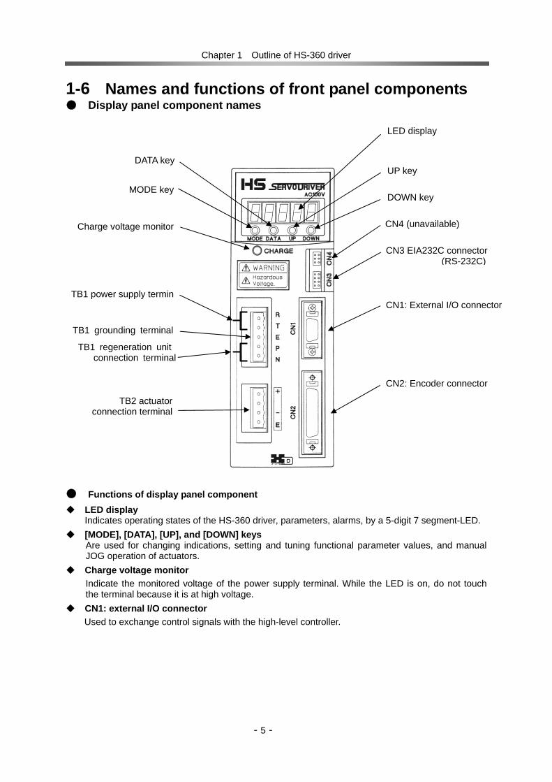
1-6 Names and functions of front panel components Display panel component names Functions of display panel component LED display
Indicates operating states of the HS-360 driver, parameters, alarms, by a 5-digit 7 segment-LED. [MODE], [DATA], [UP], and [DOWN] keys
Are used for changing indications, setting and tuning functional parameter values, and manual JOG operation of actuators.
Charge voltage monitor Indicate the monitored voltage of the power supply terminal. While the LED is on, do not touch the terminal because it is at high voltage.
CN1: external I/O connector Used to exchange control signals with the high-level controller.
Charge voltage monitor
MODE key
DATA key
LED display
UP key
DOWN key
TB1 power supply termin
TB1 grounding terminal TB1 regeneration unit
connection terminal
TB2 actuator connection terminal
CN3 EIA232C connector (RS-232C)
CN4 (unavailable)
CN1: External I/O connector
CN2: Encoder connector
Chapter 1 Outline of HS-360 driver
- 6 -
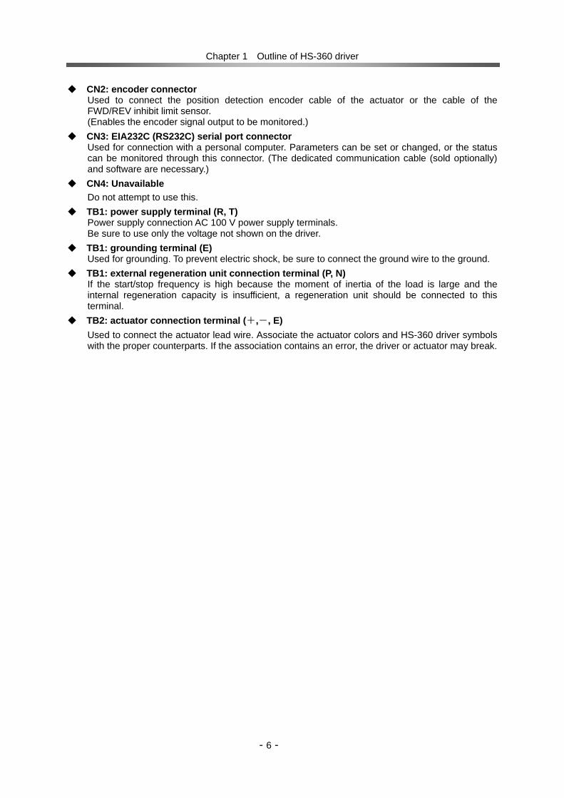
CN2: encoder connector Used to connect the position detection encoder cable of the actuator or the cable of the FWD/REV inhibit limit sensor. (Enables the encoder signal output to be monitored.)
CN3: EIA232C (RS232C) serial port connector Used for connection with a personal computer. Parameters can be set or changed, or the status can be monitored through this connector. (The dedicated communication cable (sold optionally) and software are necessary.)
CN4: Unavailable Do not attempt to use this.
TB1: power supply terminal (R, T) Power supply connection AC 100 V power supply terminals. Be sure to use only the voltage not shown on the driver.
TB1: grounding terminal (E) Used for grounding. To prevent electric shock, be sure to connect the ground wire to the ground.
TB1: external regeneration unit connection terminal (P, N) If the start/stop frequency is high because the moment of inertia of the load is large and the internal regeneration capacity is insufficient, a regeneration unit should be connected to this terminal.
TB2: actuator connection terminal (+,-, E) Used to connect the actuator lead wire. Associate the actuator colors and HS-360 driver symbols with the proper counterparts. If the association contains an error, the driver or actuator may break.

Chapter 2 Connector pin layout
- - 7
Chapter 2 Connector pin layouts 2-1 TB1 power supply terminal pin layout
Pin No. Signal name Description 1 R Power supply terminal 2 T AC 100V, 50/60Hz 3 E Grounding terminal 4 P 5 N
Regeneration unit connection terminal
(1) Applicable terminal type for cable: Plug: 231-305/026-000 (manufacturer: WAGO) (2) Applicable electric wire for cable: AWG14 (2.0mm2)
2-2 TB2 actuator cable connection terminal pin layout Pin No. Signal name Description
1 + Actuator(+)connection terminal 2 NC Non-Terminating Terminal 3 - Actuator (-) connection terminal 4 E Grounding terminal
(1) Applicable terminal type for cable: Plug: 231-304/026-000 (manufacturer: WAGO) (2) Applicable electric wire for cable: AWG16 (1.5mm2)
(3) Maximum wiring length: 10m
2-3 CN1 external I/O connector pin layout Pin
No. Signal name
Description
1 FWD+ FWD operation pulse (+) Inputs the command pulse. 2 FWD- FWD operation pulse (-) 3 REV+ REV operation pulse (+) Inputs the command pulse. P
uls
e tr
ain
4 REV- REV operation pulse (-) 5 ENABLE Servo On Turns on or off the servo. 6 ALM-RST Alarm Reset Resets the alarm output. Detected at the
edge. 7 CLEAR Error Counter Reset Resets the position error counter. Detected
at the edge. Co
ntr
ol
inp
ut
8 IN-COM Input Signal Common Used to connect the common input signal. 9 READY Ready Output while excitation current is f lowing
through the motor. 10 ALARM Alarm Output Output when an alarm occurs. 11 IN-POS In-Position Output when the position error is within the
preset range. 12 Z-IZ Encoder Phase-Z Phase-Z output from the encoder. C
on
tro
l o
utp
ut
13 OUT-COM Output Signal Common Connect the common signal (0V) of output. 14 FG Frame Ground Connected to the frame and ground.
Refer to Chapter 3 for details. (1) Applicable terminal type for cable: Cover: 10314-52F0-008
Plug: 10114-3000VE (manufacturer: 3M) (2) Applicable electric wire for cable: 0.2mm2 or more, shielded wire (3) Maximum wiring length: 3 m or less
Be sure to use a power supply voltage with the specified voltage. Otherwise, the driver may break, or fire may occur. Warning
P-N is a terminal to which the unit’s regeneration connector should be connected. If another terminal is connected here, the driver may break, or fire may occur. Warning

Chapter 2 Connector pin layout
- - 8
2-4 CN2 encoder and limit signal connector pin layout Pin No. Signal name Descr ipt ion
1 2 3 4
PG-Vcc Encoder +5V Power Supply +5V power to the encoder. Suppl ied f rom the ins ide of the servo ampl i f ier .
5 6 7 8
PG-0V Encoder Power Common Common terminal for the +5V power to the encoder.
9 A Phase-A Input 10 A Phase-A Reversal Input 11 B Phase-B Input 12 B Phase-B Reversal Input 13 Z Phase-Z Input 14 Z Phase-Z Reversal Input
Input terminal for the encoder s ignals f rom the actuator ( l ine receiver input ) .
15 NC 16 NC 17 NC 18 NC 19 NC 20 NC
Non Terminat ing Terminal Note 3
21 EPG-Vcc Encoder External
(+5V) Supply Power Used to supply the +5V power f rom the encoder f rom the outs ide. Note 2
Act
uato
r enc
oder
inpu
t
22 EPG-0V Encoder External Supply Power
Common Common terminal to supply the +5V power f rom the outs ide. Note 2
23 MON-Vcc +5V Encoder Moni tor Power Used to supply the +5V encoder moni tor pulse f rom the out l ine.
24 MON-0V Encoder Moni tor Power Common+5V power common terminal for encoder moni tor pulse output .
25 MON-A Encoder Moni tor Phase-A Output26 MON-B Encoder Moni tor Phase-B Output
Mo
nit
or
Ou
tpu
t
27 MON-Z Encoder Moni tor Phase-Z Output
Encoder moni tor pulse output (open col lector output) .
28 NC Non-Terminat ing Terminal Note 3
29 LMT-Vcc LMT Signal Power Used to supply the +24V l imi t input power f rom the outs ide.
30 NC Non-Terminat ing Terminal Note 3
31 FWD-LMT FWD Inhib i t Terminat ing terminal of FWD side ro tat ion l imi t swi tch.
32 NC Non-Terminat ing Terminal Note 3
33 REV-LMT LEV Inhib i t Terminat ing terminal of REV s ide rota t ion l imi t swi tch.
Lim
it i
np
ut
34 NC Non-Terminat ing Terminal Note 3 35
FG
36 FG Frame Ground
Connected to the f rame and power supply grounding terminal .
Note 1: Connect the shielded wire to the connector's FG terminal or ground plate. Note 2: When the internal encoder supply power voltage drops and it does not operate normally,
the external signal is supplied through this terminal. Use of this terminal requires changing the driver's internal switch settings. For details of its use, consult with a business office of Harmonic Drive Systems.
Note 3: Unavailable. Do not attempt to use this terminal (1) Applicable terminal type for cable: Cover: 10336-52F0-008 Plug: 10136-3000VE (manufacturer: 3M) (2) Applicable electric wire for cable: 0.2mm2 or more shielded twisted pair cable (3) Maximum wiring length: 10 m or less
-
-
-

Chapter 2 Connector pin layout
- - 9
2-5 CN3 serial port connector pin EIA232C-compliant (RS-232C)
CN3 EIA232C(RS232C) Pin No. Signal name Descr ipt ion
1 FG Frame Ground 2 RXD Receive Data 3 TXD Transmit Data 4 DTR Data Terminal Ready5 GND Signal Ground 6 DSR Data Set Ready 7 RTS Request To Send 8 CTS Request To Send
※ Connect the communication cable shielded wire to the Pin 1 [FG: Frame Ground]. (1) Applicable terminal type for cable: (driver) Socket terminal: DF11-2428-SCF (manufacturer: Hirose) Socket terminal: DF11-2428-SCF (manufacturer: Hirose) (2) Applicable electric wire for cable: 0.2mm2 shielded electric wire (3) Maximum wiring length: 10m or less (4) Configure the communication cables
Configure the communication cables according to the following figure:
Personal computer monitoring
On a personal computer, various items of monitored information can be displayed, parameters can be read and written, and the operational-status waveform can be displayed.
Personal computer software:
Software product name: PSF-520
Available in the Windows 2000 or XP environment
Sold optionally: EIA232C (RS-232C) communication cable Model: HDM-RS232C
Shield wire
CN4 is an unavailable connector. Attempting to use CN4 may cause the driver to break.
Caution
TXD RXD DTR SG
DSR RTS CTS FG
TXDRXDDTRSG
DSRRTSCTS
HS-360 side
Personal Computer side

Chapter 3 Control input/output
- - 10
Chapter 3 Control input/output 3-1 Command pulse input (CN1) This inputs the pulse train input to FWD+, FWD-, REV+, and REV-. This section shows a connection with a line driver command and that with an open collector command. The standard input current shall be 20mA, while the maximum input current shall be 30mA.
Connection with a line driver command
Connection with an open collector command
For +5V external power For +24V external power
If the +24V supply voltage is used with an open collector command, the connection must be made in a different way. For the supply voltage, “+5V” is the standard. For “+24V”, add a 1kΩ resistor serially to the connection. If the 1kΩ resistor is omitted, the driver may break.
Caution
Encoder signal processing
The HS-360 driver executes the internal feedback process with a signal that is obtained by multiplying the encoder feedback signal by 4. By default, the amount of movement is obtained by multiplying the encoder resolution by 4 relative to the command pulse input count. Caution
FG
220 1
2
220 3
4
1kΩ
1kΩ
HCPL-M611(HP)
HCPL-M611(HP) 14
HS-360
FWD+
FWD-
REV+
REV-
DC+5V
COM(0V)
FWD command pulse signal input
REV command pulse signal input
Shielded
FG
220 1
2
220 3
4
1kΩ
1kΩ
HCPL-M611(HP 製)
HCPL-M611(HP 製)14
HS-360
FWD+
FWD-
REV+
REV-
DC+24V
COM(0V)
FWD command pulse signal input
REV command pulse signal input
1kΩ
1kΩ
Shielded゙
FWD+
FWD-
REV+
REV-
FWD command pulse signal input
REV command pulse signal input
Equivalent to AM26LS31
HCPL-M611(HP)
HCPL-M611(HP)
FG
220
220
1kΩ
1kΩ
1
2
3
4
14
HS-360
Shielded

Chapter 3 Control input/output
- - 11
3-2 Selecting the command pulse input configuration Two ports of CN1-1&2 and CN1-3&4 are available for pulse input signals. Each of the signals input through these two ports has one of three pulse input configurations.
Setting a command configuration
[Parameter setup mode]→ [31: selecting the pulse input configuration]
3-2-1 2-pulse train (FWD and REV pulse train) As shown in the figure, “FWD commands” are input through the “FWD” port, while “REV commands” through the “REV” port. While the input is in progress, keep the other port “off”. This is also called the “FWD and REV pulse train method”, and is the default setting.
3-2-2 1-pulse train (polarity + pulse train) One pair of terminals is assigned dedicatedly for command pulse train, and the other is assigned to a sign for rotary direction. Position commands are input in the “FWD” port pair only and the “REV” port pair accepts the sign of rotary direction, as shown in the figure below. [Off] or [Low level] state is for the FWD command and [On] or [High] level is for the REV command.
3-2-3 2-pulse train (A-B phase pulses with 90-degree difference) Both port pairs receive the command pulse trains that have a 90-electronic-degree difference relative to each other as shown in the figure below. For the “FWD command”, the pulse train to the “FWD” ports advances 90 degrees from the REV port train. For the “REV command”, the “REV” port train advances from the FWD port train.
Actuator encoder monitor signals are output according to this method.
REV command
Opti-isolator: Off
Opti-isolator: Off
FWD command
REV command
Opti-isolator: On Opti-isolator: Off
FWD command
90°
REV commandFWD command
90°
FWD+
FWD-
REV+
REV-
220 1
2
220 3
4
FWD+
FWD-
REV+
REV-
220 1
2
220 3
4
FWD+
FWD-
REV+
REV-
220 1
2
220 3
4
If the other port is turned “on” while a command pulse is being input through the port, the command pulse will be disabled when being turned on.
Caution

Chapter 3 Control input/output
- - 12
Multiplication of command When the command configuration is a [2-phase pulse] type, it is possible to multiply the command pulse train by 2 or 4 for the command pulse train to an actuator.
Setting
[Parameter setup mode] → [42: multiplication of 2-phase pulse]
3-3 Control Input Signals (CN1, CN2) This section shows connection examples and details of the functions with respect to the CN1 input signals.
3-3-1 CN1 input signal connection and functions The input signals are ENABLE, ALM-RST, and CLEAR. The input circuit power supply is at DC 24V. (The input current is at approximately 10mA per circuit.) Prepare it separately.
※ Values in ( ) are the values when 5V power supply is impressed.
External power supply of 5V is needed. ※ The voltage is set to 24V during preshipment inspection. Set all “1” to “4” on the DIP switch (DS1)
on the printed circuit board in the driver to “ON” when 5V power supply is impressed to the input circuit. ※ Select only 24V or 5V as voltage for external power supply.
(Single power supply voltage)
DIP switch state Control power voltage
All ON 5V All OFF 24V
470Ω
8IN-COM
ALM-RST
ENABLE
CLEAR
DC24V(5V)
0V
External supply voltage
Alarm Reset
ENABLE
Error Counter Clear
5
6
7
14
2.7KΩ (400Ω)
HS-360
2.7KΩ (400Ω)
2.7KΩ (400Ω)
470Ω
470Ω
FWD
REV
1Input signal
Double
Quadruplicated
2 3 4
1
1
2 3 4 5 6 7 8
2 3 54 6 7 8 9 10 11 12 13 14 15 16
FG
Shielded
Configuration of DIP switch DS1 on printed circuit board
DS1

Chapter 3 Control input/output
- - 13
CN1-5 Servo on: ENABLE Functions (1) This signal turns on/off the driver circuit of the HS-360 driver.
When this input is on, the driver servo goes on, causing the driver to be ready. When it is off, the servo goes off, causing the servo to be free, or the dynamic brake to be active.
(2) The dynamic brake on/off selection can be made by selecting [Parameter setup mode] → [46: Dynamic brake on/off].
(3) The logic can be changed by selecting [Parameter setup mode] → [38: Input pin logic]. The default is 0 (CLOSE), and the signal is meaningful.
(4) If [Parameter setup mode] is selected and 1 is selected in [41: CLEAR signal functions], the error counter is also cleared and the error pulse count is set to 0.
Connection
(1) For the input circuit power supply, prepare DC 24V separately.
(2) The input current is at approximately 10mA per circuit.
CN1-6 alarm reset: ALM-RST Functions
(1) When an alarm occurs The alarm is cleared, and the driver is made ready. The edge is used for detection. If an unclearable alarm occurs, turn off the power once. In this case, turn the power on again after removing the cause of the alarm.
(2) The logic can be changed by selecting [Parameter setup mode] → [38: Input pin logic]. The default is 0 (CLOSE falling edge), and the signal is meaningful.
(3) If [Parameter setup mode] is selected and 1 is selected in [41: CLEAR signal functions], the error counter is also cleared and the error pulse count is set to 0.
Connection
(1) For the input circuit power supply, prepare DC 24V separately.
(2) The input current is at approximately 10mA per circuit.
CN1-7 error counter clear: CLEAR Functions
(1) Clear the error counter, and set the error pulse count to 0.
(2) The logic can be changed by selecting [Parameter setup mode] → [38: Input pin logic]. The default is 0 (CLOSE falling edge), and the signal is meaningful.
(3) If [Parameter mode] is selected and 0 is selected in [41: CLEAR signal functions], this input signal will be enabled. If 1 is selected there, it will be disabled.
Connection
(1) For the input circuit power supply, prepare DC 24V separately.
(2) The input current is at approximately 10mA per circuit.

Chapter 3 Control input/output
- - 14
CN1-8 input signal common: IN-COM Function
This is a common signal to “CN1-5, -6, and -7”, and supplies power form the outside for input signals.
Connection The externally supplied voltage for input signals is “+24V”.
3-3-2 CN2 input signal connection and functions FWD-LMT and REV-LMT are available for input signals. No running torque is generated at the terminal through which this signal is being input. For the input circuit power, prepare DC 24V separately (the current consumption is approximately 10mA per circuit). CN2-31 FWD inhibit: FWD-LMT CN2-33 REV inhibit: REV-LMT Functions
(1) FWD (or REV) inhibit: The actuator does not generate any forward (or reverse) torque while the input signal is being generated. If both of the input signals are generated, the actuator generates neither forward nor reverse torque. The inputs may be used to limit the motion range between limit sensors.
(2) All pulses that are input to the detected portion during limit sensor detection are ignored. (3) The logic can be changed by selecting [Parameter setup mode] → [38: Input pin logic]. The default
is 0. When the input signal causes the opti-isolator to be on, the limit function works.
Connection
(1) For the input circuit power supply, prepare DC 24V separately.
(2) The input current is at approximately 10mA per circuit.
CN2-29 LMT signal power: LMT-Vcc Function
FWD-LMT and REV-LMT are power supply terminals. Connection
Connect the 24VDC external power.
470Ω
Shielded
LMT-VCC
FWD-LMT
REV-LMT
29
31
33
DC+24V max
35/36
HS-360
470Ω
2.7KΩ
2.7KΩ
FG
Chapter 3 Control input/output
- - 15
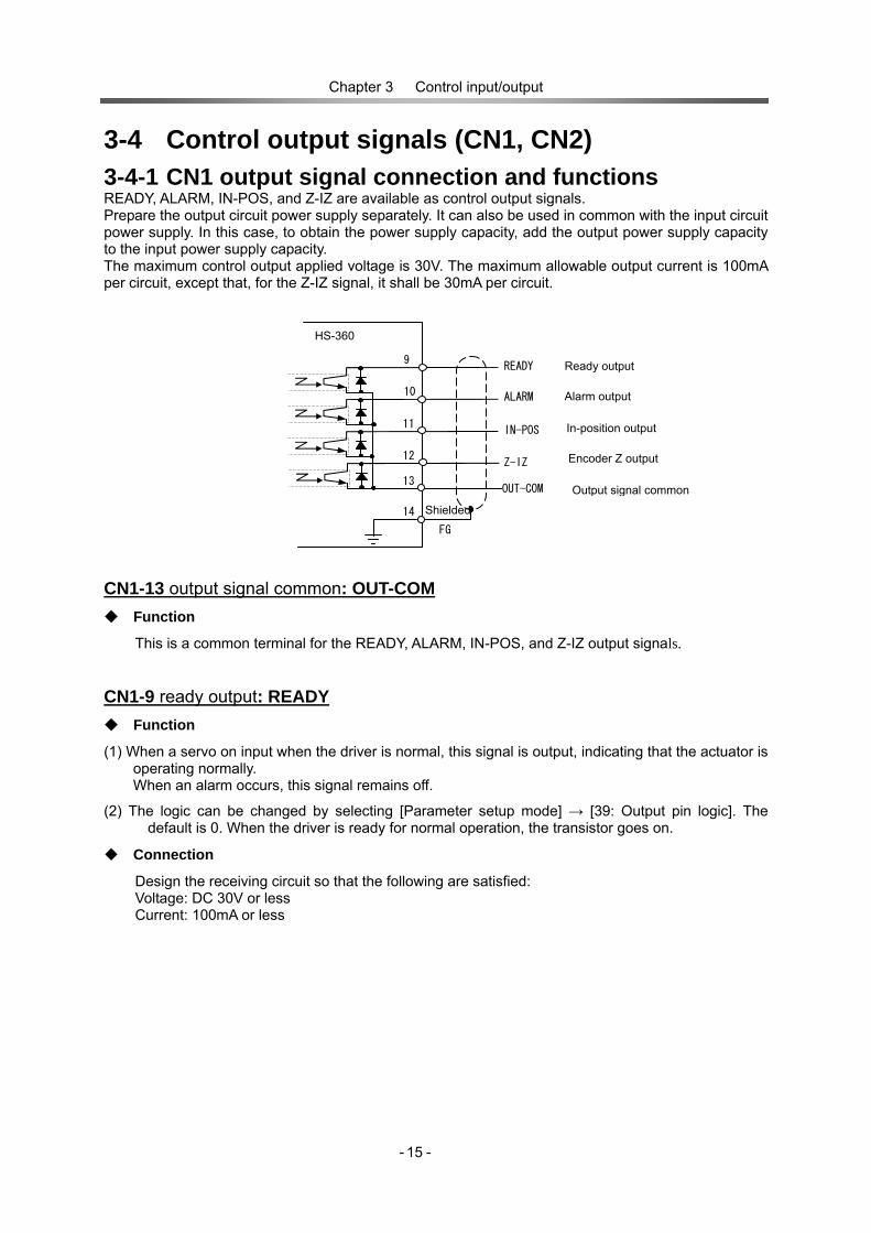
3-4 Control output signals (CN1, CN2) 3-4-1 CN1 output signal connection and functions READY, ALARM, IN-POS, and Z-IZ are available as control output signals. Prepare the output circuit power supply separately. It can also be used in common with the input circuit power supply. In this case, to obtain the power supply capacity, add the output power supply capacity to the input power supply capacity. The maximum control output applied voltage is 30V. The maximum allowable output current is 100mA per circuit, except that, for the Z-IZ signal, it shall be 30mA per circuit.
CN1-13 output signal common: OUT-COM Function
This is a common terminal for the READY, ALARM, IN-POS, and Z-IZ output signals.
CN1-9 ready output: READY Function
(1) When a servo on input when the driver is normal, this signal is output, indicating that the actuator is operating normally. When an alarm occurs, this signal remains off.
(2) The logic can be changed by selecting [Parameter setup mode] → [39: Output pin logic]. The default is 0. When the driver is ready for normal operation, the transistor goes on.
Connection
Design the receiving circuit so that the following are satisfied: Voltage: DC 30V or less Current: 100mA or less
FG
HS-360
IN-POS
ALARM
9
In-position output
Alarm output
14
READY
Z-IZ Encoder Z output
OUT-COM Output signal common
10
11
12
13
Ready output
Shielded


Chapter 3 Control input/output
- - 17
3-4-2 CN2 output signal connection and functions (encoder monitor output)
CN2-23 encoder monitor +5V power: MON-Vcc Function
This is a power supply terminal for MON-A, -B, and –Z. Connection
Connect the DC 5V external power. CN2-24 encoder monitor power common: MON-COM Function
This is a common terminal for the MON-A, -B, and -Z output signals.
CN2-25 encoder monitor Phase-A output: MON-A CN2-26 encoder monitor Phase-B output: MON-B CN2-27 encoder monitor Phase-Z output: MON-Z Function
To output the Phase-A, -B, or -Z pulse with the appropriate voltage to indicate the monitored result of the encoder. Prepare DC 5V for the output circuit power separately.
Connection
(1) The external supply voltage is required. The power supply voltage is DC 5V. (2) The monitor signal is the voltage output.
HS-360
The maximum allowable supply voltage is 5V. The maximum allowable supply voltage is 5V. Connection of any voltage exceeding 5V may break the driver.
Caution
Shielded HCPL-M611(HP)
MON-A Encoder monitor Phase-A signal output
MON-B Encoder monitor Phase-B signal output
MON-Z Encoder monitor Phase-Z signal output
MON-Vcc Encoder monitor + 5v power
MON-COM Encoder monitor power common
25
35/36
26
27
24
23
FG
2.2KΩ
2.2KΩ
2.2KΩ

Chapter 3 Control input/output
- - 18
3-5 Encoder input (CN2) Function
Connect this with the DC servo actuator encoder.
Connection
(1) Connect the shielded wire securely to CN1-35 and 36.
A-
B-
Z-
Equivalent toAM26LS31
DC servo actuator
A
B
Z
PG-Vcc
PG-0V
+5V
0V
220Ω
220Ω
220Ω
Driver HS-360
9
10
11
12
13
14
1~4
5~8
FG 35,36 Equivalent to 26C32
Shielded
Only a line driver can be connected to the encoder. Encoder output such as an open collector or TTL cannot be connected.
Caution

Chapter 3 Control input/output
- - 19
3-6 External connection examples The following is an external connection example where the pulse output
configuration is a line driver. The command configuration is 2-pulse train.
Note: The required voltage may be AC 100V, depending on the combination with the actuator. Be sure to use the product with the predetermined voltage ※:Be certain to connect the mounting part of the actuator and “E” of TB2 by wire. An encoder error (Alarm 02) may result if wire is not installed.
CN1
HS-360 シリーズ
2201
2
2203
4
IN-POS
ALARM
9
位置決め完了出力
アラーム出力
14
READY 動作準備完了出力
Z-IZ エンコーダZ出力
OUT-COM 出力信号コモン
10
11
12
13
TB1 電源トランス
電源入力AC100V(50/60Hz)
R
T
E
Line filter
L/F
NFB CP
P
N
回生ユニット
8IN-COM
ALM-RST
ENABLE
CLEAR
DC24V
0V 外部供給電源
アラームリセット
イネーブル
偏差カウンタクリア
5
6
7 2.7k
2.7k
2.7k
35/36
シールド
CN2
1~4
5~8
910
12
13
+5V
A
GND
11
14
B
B
Z
Z
E
LMT-VCC
FWD-LMT
REV-LMT
DC+24V
Input of operation limit signal
2.7k
2.7k
29
31
33
FWD+
FWD-
REV+
REV-
正転指令パルス信号入力
逆転指令パルス信号入力
DC reactor (For HS-360-1A only)
TB2
+
-
EDC Servo Actuator
RH/RHS/RFS/LA Series
M
金属(※)
FG
FG
FG
HS-360 Series
FWD command pulse signal input
REV command pulse signal input
External power supply
Alarm Reset
Error Counter Clear
Ready output
Alarm output
In-position output
Encoder Z output
Output Signal Common
Shield
Shield
Shield
Power transformer
Power input
Regeneration unit
Encoder Monitor +5V Power
Encoder Monitor Power Common
Encoder Monitor Phase-A signal outpt
Encoder Monitor Phase-B signal output
Encoder Monitor Phase-Z signal output
Metal(※)
Emable
25
35/36
26
27
24
23 Encoder Monitor +5V Power MON-Vcc
Encoder Monitor Power Common MON-COM
A

Chapter 3 Control input/output
- - 20
The following is an external connection example where the pulse output
configuration is open collector. The command configuration is 2-pulse train.
Note: The required voltage may be AC 100, depending on the combination with the actuator. Be sure to use the product with the predetermined. ※:Be certain to connect the mounting part of the actuator and “E” of TB2 by wire. An encoder error (Alarm 02) may result if wire is not installed.
CN1
HS-360 シリーズ
IN-POS
ALARM
9
位置決め完了出力
アラーム出力
14
READY 動作準備完了出力
Z-IZ エンコーダZ出力
OUT-COM 出力信号コモン
10
11
12
13
TB1 電源トランス
電源入力AC100V(50/60Hz)
R
T
E
ラインフィルタ
L/F
NFB CP
P
N
回生ユニット
CN2
E
1~4
5~8
910
12
13
+5V
A
GND
11
14
B
B
Z
Z
LMT-VCC
FWD-LMT
REV-LMT
DC+24V
Input of operation limit signal
FWD+
FWD-
REV+
REV-
+5V
COM(0V)
正転指令パルス信号入力
逆転指令パルス信号入力
2201
2
2203
4
8IN-COM
ALM-RST
ENABLE
CLEAR
DC24V
0V 外部供給電源
アラームリセット
イネーブル
偏差カウンタクリア
5
6
7 2.7k
2.7k
2.7k
DC reactor (For HS-360-1A only)
TB2
DC Servo Actuator RH/RHS/RFS/LA Series
+
-
E
M
エンコーダモニタA相信号出力
エンコーダモニタB相信号出力
エンコーダモニタZ相信号出力
エンコーダモニタ用+5V電源
エンコーダモニタ用電源コモン
25
35/36
26
27
24
23
FG
FG
FG
Line filter Power transformer
Power input
HS-360 Series
FWD command pulse signal input
REV command pulse signal input
External power supply
Enable
Alarm Reset
Error Counter Clear
Shield
Shield
Shield
2.7k
2.7k
29
31
33
Ready output
Alarm output
In-position output
Encoder Z output
Output Signal Common
Encoder Monitor +5V Power MON-Vcc
Encoder Monitor Phase-A signal output
Encoder Monitor Phase-B signal output
Encoder Monitor Phase-Z signal output
Encoder Monitor Power Common MON-COM
Regeneration unit
金属(※)Metal(※)
A

Chapter 4 Installing driver
- - 21
Chapter 4 Installing driver 4-1 Receiving Inspection Check the followings when products are unpackaged.
Inspection procedure (1) Check the shipping item for any damage that may have been caused during transportation. If the item is damaged, immediately contact the dealer it was purchased from.
(2) On its side, the driver has the nameplate shown on the right.
The model of the driver is denoted in the "TYPE" field on the nameplate.
Check that the delivered model is exactly the product you ordered. Should it be a different model, immediately contact the dealer.
The model indication represents the following:
(3) The "ADJ." field on the nameplate shows the DC servo actuator model that must be used
in combination with this HS-360 driver.
(4) Checking accessories The following parts are attached as accessories. Check them.
1) CN1 External I/O Connector Cover :10314-52F0-008
Plug :10114-3000VE (Manufacture:3M)
2) CN2 Encoder Connector Cover :10336-52F0-008
Plug :10136-3000VE (Manufacture:3M)
3) TB1 Power supply terminal Plug :231-305/026-000 (Manufacture:WAGO)
4) TB2 Actuator connector terminal Plug :231-304/026-000 (Manufacture:WAGO)
5) TB1,TB2 Operation lever:231-131
6) DC Reactor(HS-360-1A Only) :15mH reactor
Do not combine the driver with any actuator that differs from the one shown on the nameplate. The characteristics of the HS-360 driver have been factory-set according to the associated actuator. Combination with an incompatible actuator may cause it to burn because of insufficient torque or over current. If this happens, you may be injured, or fire may occur.
Warning
HS-360-1 A HS-360 DC servo driver
Rated current 1:1A or 1.4A 3:3.2A
Maximum current types A: 1.0A B: 2.6A C: 3.7A D: 4.2A

Chapter 4 Installing driver
- - 22
(5) The driver input power supply voltage is shown in the "INPUT VOL." on the nameplate and at the top of the front panel of the driver. (Refer to Section 1-6, "Front panel".)
4-2 Notices on handling drivers The drivers are electronic devices. Handle them with care and take the following precautions.
Do not connect the driver to any power supply the voltage of which differs from the value specified on the nameplate. If the driver is connected to any power supply the voltage of which differs from the value specified on the nameplate, it may break, resulting in injury or fire. 100:Single-phase, AC 100V
(1) Because the case is made of plastic, do not apply excess force or shock.
(2) The vibration resistance of the driver is 4.9m/s2 (10 to 55Hz). Do not mount or transport the HS-360 driver in a manner where it would be subjected to high levels of vibration.
(3) Do not put the HS-360 driver on the place from where it can easily fall down.
(4) Do not put anything on the driver. The case of the driver may break.
(5) The allowable storage temperature is from -20°C to +85°C. Do not expose it to sunlight for long periods of time, and do not store it in areas where temperatures are likely to fluctuate greatly.
(6) The allowable storage relative humidity is less than 90%. Do not store it in highly humid place or in areas where temperatures are likely to fluctuate greatly.
(7) Do not store the driver in areas where in corrosive gas or particles may be present
(8) When the driver is to be powered on again after the driver input power is turned off, do this after a lapse of 30s or more. It takes longer time to complete the startup due to the residual charge.
Caution
Warning
(1) Do not drop screws, solder balls, wire chips, or any other foreign objects through the ventilation gaps of the driver. Failure to observe this caution may result in electric shock or personal injury.
(2) Do not insert electric wire, steel wire, or a screwdriver through the ventilation gaps of the driver Failure to observe this caution may result in electric shock or personal injury.
Warning

Chapter 4 Installing driver
- - 23
4-3 Location and installation 4-3-1 Environment of location The environmental conditions of the location are as follows: Service temperature: 0°C to +50°C
Use the driver in a cabinet. The temperature in the cabinet can be higher than the atmosphere because of power loss of the housed devices and its size. Plan the cabinet size, ventilation system, and device locations so the ambient temperature of the driver, which is always less than 50°C.
Service humidity: less than 90% relative humidity, without condensation Make sure that water condensation does not occur due to fluctuating temperatures in the storage area or because of frequent heat-and-cool (run-and-stop) operations.
Vibration: less than 4.9m/s2 (0.5G) (10Hz to 55Hz) When there is a great deal of vibration near the driver, attach a shock absorber under the base to dampen the vibration.
Impact: less than 19.6m/s2 (2G)
Make sure that dust, water condensation, metal powder, corrosive gas, water, water drops, or oil mist is not exposed to the HS-360 driver
Do not install the driver in a corrosive gas environment, because the gas may cause damage to connecting parts (connectors, etc.). Install the driver in a cabinet. Do not expose it to the sunlight.
4-3-2 Notices on installation Install the driver vertically and allow for wide spaces for air to flow sufficiently. Leave 30mm or more from walls, 50mm or more from floor and 100mm from ceiling, and adjacent devices as shown the figure below. When planning the ventilation system for the cabinet refer to the table below, which lists the power consumption of the driver.
Driver HS-360-1* HS-360-3 Power
consumption 20W 40W

Chapter 4 Installing driver
- - 24
4-3-3 Installing The HS-360 driver should be mounted on a wall as shown in the figure to the right. Two mounting holes are provided on the back of the driver. The thickness of the wall should be more than 2mm. Procedure (1)Screw an M5 machine screw in the tapped
hole on the wall. (2)Put the power mounting hole (cut hole) of
the back of the driver on the M5 screw. (3)Screw tightly through the upper mounting hole
with M5 screws. (4)Tighten the lower M5 screw.
4-4 Suppressing noise The HS-360 driver employs an IPM (power module) with a PWM control for main circuit. As the IPM generates switching noise by high-speed power switching, the noise may cause incorrect motion of other equipment or radio noise interference due to poor cabling or poor grounding. In addition, it is necessary to provide proper cable management in order to suppress incorrect motion of the HS-360 driver by external noise from hosts, which contain electronic components, such as a CPU. To prevent troubles by noise emissions always install cabling and grounding as follows:
4-4-1 Devices for grounding Refer to the figure below when grounding all devices of the system.
Note 1: For the grounding line filters refer to [4-4-2 installing noise filter].
HD Noise Filter
Power Transformer
Noise Filter
Power Transformer
Noise Filter
Ground
Customer’s signal generating devices as a program logic controller
CN1
E
M
Note 1 Note 1
RT
+
CN2
HS-360
3.5mm2 or thicker
Grounding to the earth (One-point-grounding is essential)3.5mm2 or thicker
Servo Actuator
Power Supply single phases
Note 1
3.5mm2 or thicker
-
Metal

Chapter 4 Installing driver
- - 25
Grounding motor frame When actuators are grounded at driven machine through the motor frame, current flows through floating capacity (Cf) of the motor from power amplifier of the driver. To avoid influence of the current, always connect the ground terminal (motor frame) of the motor to the ground terminal of the driver, and connect the ground terminal of the driver to the ground directly.
Grounding ducts When the motor cables are housed in a metal conduit or a metal box, ground their metal parts. The ground should be connected to earth at a single point.
4-4-2 Installing noise filters Noise filters are recommended to guard against incorrect motion caused by impulse noise that may be emitted from power line and to suppress noise emissions to the line from inside of the driver simultaneously. When plural drivers are used, ground noise filters for each driver. Select bi-directional noise filters that can suppress external and internal noise. Recommended noise filters are listed in the figure below:
Driver Model Ratings Manufacturer HS-360-1* SUP-P5H-EPR 250V,5A HS-360-3 SUP-P10H-EPR 250V, 10A
Okaya Electrics
Install the noise filters and the HS-360 driver as near as possible with one another. Install the noise filters to the lines of the electric devices other than the HS-360 driver in the same way. Especially, always install the noise filters to the source of high frequency noise, such as electric welders and electrical discharge machines. Incorrect use of noise filters can seriously reduce its effectiveness. Inspect them with the following instructions: Separate the filtered side and the unfiltered side of the power supply cables from each other. Do not bundle both together. Do not encase them within the same duct.
Do not bundle the grounding cable with the filtered side of power cables or signal wires. Do not encase them within the same duct.
Avoid daisy-chain wiring of ground cables. Ground them to a frame box or ground plate at a single point.
Filter
Ground in
Filter
Ground in Box Ground in Box
BAD GOOD
(a)
Filter Filter
Ground in BoxGround in Box
BAD GOOD
Grounding wires near power lines is acceptable.
(b)
Filter Filter
Ground in BoxGround in Box
BAD GOOD
E E
Wire Shield
E E
(c)
Wire Shield

Chapter 4 Installing driver
- - 26
4-4-3 Instructions for cabling In addition to the noise suppression mentioned previously, one must also follow these instructions: (1) Use shield cables for I/O signals. When a host controls several drivers, prepare I/O signal cables
for each driver individually. (2) Use twisted pair cables for encoder signal cables. (3) Make the length of signal cables as short as possible.
(a) I/O signal cable: 3m or less (b) Encoder signal cable (user’s responsibility): 10m or less, providing that the condition of wire conductivity is less than 0.04 ohm/m.
(4) Install surge protector devices to magnetic relays coils, magnetic switches, and solenoids. (5) Separate power cables (power source cables and motor cables) and I/O signal cables by more
than 30cm. Do not encase both cables in one pipe or duct, and do not bundle them. (6) As the HS-360 driver is designed for industrial use, it provides no specific radio interference
provisions. Accordingly, line filters should be inserted for the power supply cables in the event that the driver: - is used in the vicinity of private residences. - causes apparent radio interference.

Chapter 4 Installing driver
- - 27
4-5 Connecting power cables 4-5-1 Instructions for power supply
4-5-2 Power cables and ground wires The minimum allowable wire sizes of power cables, ground wires, and other cables are listed below. We recommend the thickest wires possible.
Allowable Wire Sizes (mm2) Terminal/connector Symbol HS-360-1A HS-360-1B,1C,1D HS-360-3
Power supply terminal R,T 1.25
Actuator connection terminal +,- 0.3 0.5 0.75
Connection terminal E 3.5
Regeneration unit connection terminal P,N 0.75
External I/O connector CN1 0.2mm2 shielded cable
Encoder connector CN2 0.3mm2 twist pair shielded cable Note 1. When bundling wires or encasing into conduits (plastic or metal pipes), use the
wire of one upper size. Note2. In hot environments, such as the temperature in a cabinet, use heat-resistant
cable (IV or HIV).
(1) Connect the power cable to the HS-360 driver only after installing the driver on a wall.
(2) Ground the HS-360 driver, to avoid electric shock, malfunctions caused by external noise, and for the suppression of radio noise emissions. Caution
Before connecting the power cable to the HS-360 driver, turn-off the electricity to avoid electric shock. Failure to observe this caution may result in electric shock or personal injury.
Warning

Chapter 4 Installing driver
- - 28
4-5-3 Connecting power cables The “terminal block for the power” is located on the front panel of the HS-360 driver. Use the operating lever annexed to the optional connector shown below. Shown the figure to the right, strip the end of wires of the power supply cable and the motor cable, and connect wires to each terminal firmly. Install “isolation transformer” and “noise filter” in the power lines to avoid electric shock and to guard against malfunctions caused by external noise. If the regeneration unit is required, connect this with "P, N" terminal.
The driver contains a surge-current-suppress-circuit of capacitor type. Although the circuit reduces line voltage fluctuation, avoid daisy-chain wiring of the power lines, and connect units with a main switch.
4-5-4 Isolation transformer (sold optionally) The use of an isolation transformer is recommended to prevent problems caused by improper grounding and external noises. Optional transformers for single-phase power supply are available as follows:
Isolation transformer Driver
PT1-10002-100 HS-360-1A,1B,1C,1D PT1-10004-100 HS-360-3
HS-360
Main switch
Other device
Otherdevice
Power
Other device
Other device
Power
Good cable management Bad cable management
Main switch
HS-360
7mm
Plug: 231-305/026-000 (Manufacture: WAGO)
HS-360
ENoise filter
RTNF
Isolation transformer
PN
Regeneration unit
PT1-100 02-100
Isolation transfer: PT1 Series
2nd Volt 100 : AC 100V 200 : AC 200V
2nd current 02 : 2A 04 : 4A
Prim. volt 100 : AC100V 115 : AC115V 200 : AC200V 220 : AC220V

Chapter 4 Installing driver
- - 29
4-5-5 Protecting the power line Be sure to use a circuit breaker (MCB) or circuit protector for the power line in order to protect it. Select the circuit breaker or protector based on the following table:
Combination of actuator and driver HS-360-1A,1B,1C,1D HS-360-3
Power interrupting capacity (A) of circuit protector Note 1
5 10
Required power capacity per driver (Kva) Note2 0.1 0.3
Power-on rush current (A) Note 3 8 15
Note 1: Use lag type for circuit protector and motor brake for brake Note 2: When the actuator allowable continuous output is in progress. Note 3: When the ambient temperature is 25°C.
4-6 Connecting the ground wire Use an electric wire of the following size or more:
Terminal/connector Symbol Minimum allowable wire size (mm2) Grounding terminal (E) Grounding mark 3.5
The HS-360 driver is provided with grounding terminal. Make connection between the ground with the cabinet and the grounding wire from the actuator. The leakage current is generated at the maximum of 10mA. Be sure to connect an electric wire with a cross section of 3.5mm2 or more to the grounding terminal.
4-7 Connecting the actuator cable Connect the actuator cable to the “+”, “-” and “E” terminals on the driver, as shown in the figure below. To do this, use the operating lever included with the product (refer to the figure below). Before beginning, examine the phase sequence in an actuator technical material. Make connection between the terminals marked with the same symbol. For treatment of the cable end, refer to “Section 4-5-3, Connecting power cables".
Plug:231-304/026-000 (Manufacturer WAGO)

Chapter 4 Installing driver
- - 30
4-8 Connecting cables for the encoder and the I/O 4-8-1 Preparing the encoder cable and the I/ O cable Follow these instructions for the preparation of the encoder cable and the I/O cable. (1) Use twisted pair cables for I/O signal cables and for encoder signal cables. When a host controls
several drivers, install I/O signal cables for each driver individually. (2) Make the length of signal cables as short as possible.
1I/O signal cable: 3m or less 2Encoder cable (user’s responsibility): 10m or less, providing that the condition of wire conductivity is less than 0.04 ohm/m
(4) Separate power cables (power source cables and motor cables) and I/O signal cables more than 30cm. Do not encase both cables in one pipe or duct, nor bundle them.
Terminals/Connectors Symbol Allowable Wire Sizes (mm2) External I/O connector CN1 0.2mm2 twist pair cable, or twist pair whole-shielded cable
Encoder connectors CN2 0.3mm2 twist pair shielded cable
4-8-2 Pin layout of external I/O connector (CN1) The models and the pin layout of the external I/O connectors are as follows: Plug: Model 10114-3000VE Manufacturer: 3M Cover: Model 10314-52F0-008 Manufacturer: 3M
4-8-3 Pin layout of encoder connector (CN2) The models and the pin layout of the encoder connectors are as follows: Plug: Model 10136-3000VE Manufacturer: 3M Cover: Model 10336-52F0-008 Manufacturer: 3M
5 ENABLE
3 REV+
1 FWD+
7 CLEAR
6 ALM-RST
4 REV-
2 FWD-
13 OUT-COM
11 IN-POS
9 READY
14 FG
12 Z-IZ
10 ALARM
8 IN-COM
Viewed from soldering side
Viewed from soldering side
5 PG-0V
3
PG-Vcc
1PG-Vcc
7 PG-0V
6 PG-0V
4
PG-Vcc 2
PG-Vcc
13Z
11B
9A
14― Z
12― B
10― A
8PG-0V
17
15
18 16
23 MON -Vcc
21 EPG -Vcc
19
25 MON-A
24 MON -COM
22 EPG -0V
20
31FWD-LMT
29LMT-Vcc
27MON-Z
32
30 28
26MON-B
35FG
33REV-LMT
36FG
34
Chapter 4 Installing driver
- - 31
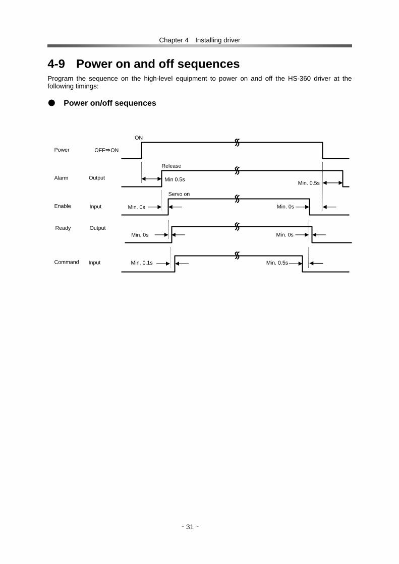
4-9 Power on and off sequences Program the sequence on the high-level equipment to power on and off the HS-360 driver at the following timings: Power on/off sequences
ON
Release
Servo on
Power
Alarm
Enable
Command
OFF⇒ON
Output
Input
Input
Min 0.5s Min. 0.5s
Min. 0s Min. 0s
Min. 0.1s Min. 0.5s
Min. 0s Min. 0s Ready Output

Chapter 5 Operations
- - 32
Chapter 5 Operations Follow these instructions prior to operations.
5-1 Trial run
Drive the actuator only without load during the trial run. Objectives for the trial run (1) Verifying the power cable wiring (2) Verifying the motor cable wiring (the servomotor cable and the encoder cable)
Trial run procedure Powering on the driver and checking the power supply, motor, and encoder wiring
(1) Power on the driver Check that no failure has occurred. ⇒ The state data mode display appears on the HS-360 driver.
1. Inspect the cabling before turning the power ON and correct poor cabling if necessary.
(1) Is the cabling correct? (2) Is there any temporary cabling? Are all wires connected to the
terminals? (3) Are there any loose terminal connections? (4) Are the wires grounded properly?
2. Never wire the unit or make changes to the wiring while the power is ON. Turn the power OFF first.
3. Clean around the equipment. Make sure there are no wire chips or tools in the equipment.
1. Complete the trial run before actual operation.
2. Drive the actuator only during the trial run; disconnect the actuator from the driven mechanism or load. Caution
Warning
Chapter 5 Operations
- - 33
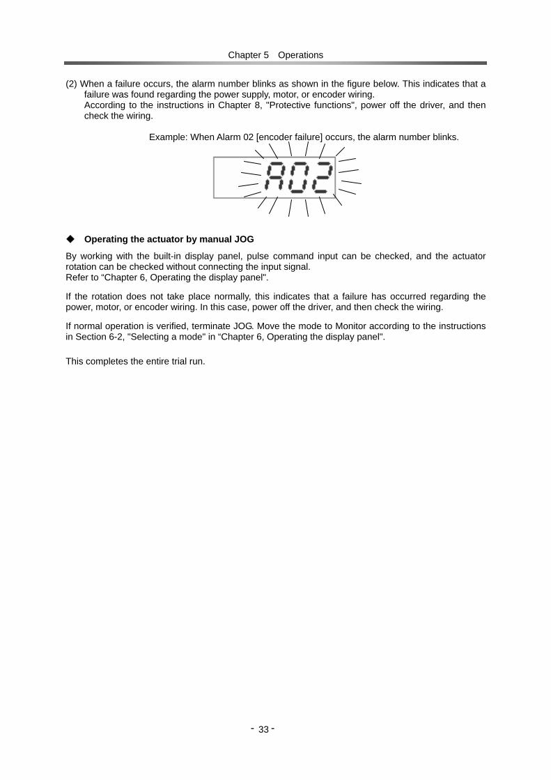
(2) When a failure occurs, the alarm number blinks as shown in the figure below. This indicates that a failure was found regarding the power supply, motor, or encoder wiring. According to the instructions in Chapter 8, "Protective functions", power off the driver, and then check the wiring.
Example: When Alarm 02 [encoder failure] occurs, the alarm number blinks.
Operating the actuator by manual JOG
By working with the built-in display panel, pulse command input can be checked, and the actuator rotation can be checked without connecting the input signal. Refer to “Chapter 6, Operating the display panel". If the rotation does not take place normally, this indicates that a failure has occurred regarding the power, motor, or encoder wiring. In this case, power off the driver, and then check the wiring. If normal operation is verified, terminate JOG. Move the mode to Monitor according to the instructions in Section 6-2, "Selecting a mode" in “Chapter 6, Operating the display panel".
This completes the entire trial run.

Chapter 5 Operations
- - 34
5-2 Usual operation No particular operations are required because the HS-360 driver operates according to the commands from the higher-level system. When a failure occurs, the alarm number blinks as in the figure below. In this case, power off the driver and remove the alarm cause according to the instructions in “Chapter 8, Protective functions" and “Chapter 9, Troubleshooting”.
Example: When Alarm 02 [encoder failure] occurs, the alarm number blinks.
If the actuator does not rotate in response to pulse input while the normal state is on display, take action according to the instructions in a “Section 9-1, The actuator does not rotate" in “Chapter 9, Troubleshooting". This section describes notices on usual operations and daily maintenance.
5-2-1 Notices for daily operations
1. Do not make any wiring while power is active. Disconnecting wires or connectors while power is active may cause electric shock or abnormal mechanical motion resulting in serious physical injury.
2. Immediately after the driver is powered off, do not touch any terminal. The driver contains electricity inside also after being powered off. Do not touch any terminal until the charge voltage monitor LED goes out on the display panel.
3. Do not operate drivers with frequent ON/OFF operation. Frequent power ON/OFF operation may cause deterioration of electronic elements. Start/stop operation should be performed with using input signals.
Warning


Chapter 6 Operating the display panel
- - 36
Chapter 6 Operating the display panel The display panel of the driver is equipped with a five-digit LED display segment and four operation keys. This display segment can display all the information, and allows you to make all the adjustments, settings, and operations.
6-1 Outline of modes The driver provides the following four modes: Monitor mode While the driver is operating normally, its operating state is displayed with bits (refer to 6-3-1). When an alarm occurs, the alarm number blinks (refer to 6-3-2). The view is forcibly changed to this display even when an alarm occurs when a non-monitor mode has been selected. When the driver is powered on, the “monitor mode” page appears. After the driver is powered on, the mode can be changed from this page to another mode by operating a key as shown in the figure below. Parameter setup mode This mode allows you to view or change servo parameters. Parameters related to the basics of operation, including operation related to the higher-level system (e.g., loop gains, input signal configurations, electronic gear functions, speed/torque limits). Numeric monitor mode This mode displays the alarm position, speed, torque data, and other information in real time. When the driver is operating normally, the servo operation state is displayed with bits. JOG operation mode This mode allows JOG operation, and includes the functions required for testing in system construction.
6-2 Changing a mode Immediately after being powered on, the driver automatically enters the “monitor mode”. The mode can be changed by using the “MODE” key on the front of the driver.
JOG operation mode
MODE
Power on
Monitor mode
Parameter setup mode Numeric monitor mode
MODE
MODE
MODE

Chapter 6 Operating the display panel
- - 37
6-3 Monitor mode display details 6-3-1 Servo state display When the middle character A remains displayed rather than blinking, this indicates that the driver is operating normally. The state is displayed on bit.
Bit Description V-ON On while the AC 100 V supply voltage is
being input. BBLK On while the servomotor is energized.
VOVR On while the power supply voltage is being input with the servomotor energized.
TOVR On while the torque is restricted. SOVR On while the speed is restricted.
6-3-2 Alarm state display When an alarm occurs, the alarm number blinks as shown in the figure below. Even when an alarm occurs when a non-monitor mode has been selected, the view is forcibly changed to this display. In this case, pressing the MODE key changes the mode. To take action against display of an alarm number, refer to “Chapter 8, Protective functions".
Example: When Alarm 02 [encoder failure] occurs, the alarm number blinks.
6-3-3 Resetting the alarm Some alarms can be reset by pressing the UP and DOWN keys together in the monitor mode. If an alarm occurs that cannot be reset, power off the driver once. (For alarms that cannot be reset, refer to “Section 8-1, Protective functions".)
6-3-4 Displaying the alarm history When the servo state is on display or alarm number is blinking, the alarm history is displayed pressing the DATA key. The alarm history code can be changed by pressing the UP or DOWN key at this time. The history contains up to eight alarm events.
Example: When Alarm 01 [overload failure] occurs as the sixth last alarm:
6-3-5 Clearing the alarm history Alarm history information can be cleared by pressing the UP and DOWN keys together when an alarm is on display. The data disappears from the alarm number field at this time.
TOVR
SOVR
V-ON
BBLK
VOVR

Chapter 6 Operating the display panel
- - 38
6-4 Outline of parameter setup mode This mode allows you to view the servo or change parameters. Parameters related to the basics of operation, including operation related to the higher-level system (e.g., loop gains, input signal configurations, electronic gear functions, speed/torque limits). The parameters are detailed in Chapter 7.
6-4-1 Operating parameter setup mode Parameters can be viewed or changed using the procedure below. Change to a parameter causes the data to be rewritten in EEPROM. (The changes to the data are also after the driver is powered off.)
Non-parameter setup mode
The mode is changed to parameter details change mode by pressing the DATA key for 1s or longer.
Press the UP and DOWN keys to select the desired parameter number to display or change
Select the parameter mode by pressing the MODE key repeatedly.
Press the DATA key. The initial state returns by pressing it again for a short term.
Press the UP and DOWN keys to change the currently blinking digit.
Press the DATA key to move the blink to the next digit.
Parameter mode
Parameter No
Parameter details displayed
Parameter change mode
Least significant digit
Pressing the DATA key stores the currently displayed value into memory.
Repeat these steps up to the least significant digit.
If the entered data exceeds the parameter setting range, or the MODE key is pressed during a change process, the pre-rewritten, or initial, data is displayed with the data rewrite canceled. For performing operations for the parameter to display the higher or lower digit, refer to Section 6-7.
Press the DATA key to return to the currently operated parameter number.

Chapter 6 Operating the display panel
- - 39
6-5 Outline of numeric monitor mode The numeric monitor mode displays the position, speed, torque data, and other information about the actuator.
6-5-1 Numeric monitor list Monitor No. Contents Unit Digits displayed
00 Number of feedback pulses (encoder value multiplied by 4) Pulses High and low-order
digits
01 Number of command pulses (encoder value multiplied by 4) Pulses High and low-order
digits
02 Number of error pulses (encoder value multiplied by 4) Pulses High and low-order
digits 04 Current speed (motor shaft) display [r/min] Low order digits only
05 Command speed (motor shaft) display [r/min] Low order digits only
06 Torque command Rated torque (%) Low order digits only 07 Effective duty ratio display Rated torque (%) Low order digits only 09 Torque peak display Rated torque (%) Low order digits only 14 Command pulse frequency display Frequency (kHz) Low order digits only 15 Stop cause display ― Refer to Section 6-5-4. 16 Control state display ― Refer to Section 6-5-5. 17 I/O state display ― Refer to Section 6-5-6.
6-5-2 Displaying numeric monitor data
If the monitor data value in the high or low-order digits is displayed, proceed with the following procedure:
Non-numeric monitor mode
Press the UP or DOWN key to select the desired monitor number to display.
Select the numeric monitor mode by pressing the MODE key repeatedly.
Pressing the DATA key displays the monitor data value. Pressing the DATA key again displays returns the view to the monitor number display.
Numeric monitor mode
Monitor number
Monitor data
Pressing the DATA key displays the high-order digit monitor data. Pressing the DATA key again returns the view to the monitor number display.
Pressing the UP key displays the low-order digit monitor data.
High-order digits
Low-order digits

Chapter 6 Operating the display panel
- - 40
6-5-3 Clearing the torque peak By pressing and holding down the UP and DOWN keys together while monitor number “9: Torque peak" is on display, the peak is updated with that of the torque values resulting while the keys are held down. 6-5-4 Displaying stop cause Selecting Monitor No. 15 displays the stop cause.
6-5-5 Displaying control state Selecting Monitor No. 16 displays the servo state.
Control state display Bit Description V-ON On when the AC 100 V supply voltage is being input. ALARM On when an alarm has occurred. ENABLE On when the servo is on. FWD-LMT On when the FWD-LMT external input signal has been detected. REV-LMT On when the REV-LMT external input signal has been detected. POVR On when a position error allowance excessive alarm has occurred. SOVR On when the speed limit is working. TOVR On when the torque limit is working. IN-POS On when positioning is complete.
VOVR On while over-voltage for power supply (DC 380V or more) is being applied with the servo on.
BBLK On while the servomotor is energized. 6-5-6 Displaying I/O state Selecting Monitor No. 17 displays the control I/O terminal state. For both the input and output, the segments light up when the contact closes.
Input pulse 0 Input of FWD-LMT signal input
Input of REV-LMT signal input
ENABLE is off
Alarm occuring
V-ON
ENABLE
ALARM
REV-LMT FWD-LMT POVR IN-POS
VOVR
TOVR SOVR
BBLK
Input Output READY
IN-POS
Z-IZ
CLEAR REV-LMT
FWD-LMT
ALM-RST
ENABLE
ALARM

Chapter 6 Operating the display panel
- - 41
6-6 JOG operation mode The JOG mode enables JOG operations. 6-6-1 JOG operations procedure When JOG is off, the driver operates according to the pulse input commands. Even if the servo is on, the driver cannot be operated in JOG mode unless JOG is on. Note
Note: When JOG is on, the mode cannot be changed even if the MODE key is pressed.
Non-parameter mode
Select the JOG mode by pressing the MODE key repeatedly.
Turn on/off JOG using the DATA key.
・ The actuator rotates in forward direction while the UP key is held own, and in reverse order while the DOWN key is held own. ・ When the key is released, the actuator stops.
JOG mode (Servo off, JOG off)
JOG operation
JOG mode (Servo on, JOG on)
JOG mode (Servo on, JOG off)
During JOG, the segments rotate in the rotary direction of the motor. However, if 1 has been set for [09: Rotary direction command] of [Parameter setup mode], the actuator will rotate in the reverse direction to the actuator rotation displayed with segments.

Chapter 6 Operating the display panel
- - 42
JOG operation patterns JOG operates in an environment that has been set up by the following parameters:
[19: JOG operation speed] [20: JOG feed pulse count] [40: JOG acceleration/deceleration time constant] [43: JOG character-S selection]
For details, refer to “Chapter 7-2, Parameter details Step feed area: When the “UP” or “DOWN” key is pressed, the forward or reverse step takes place
for the pulse count that has been set for [20: JOG feed pulse count] of [Parameter setup mode].
Consecutive feed actuator: When the “UP” or “DOWN” key is pressed and held down, the
operation in the step feed takes places; the consecutive feed actuator is then entered, and the rotation continues at the speed that has been set for [19: JOG speed] of [Parameter setup mode]. Releasing the “UP” or “DOWN” key causes the actuator to decelerate and stop.
JOG operation speed
S-ON
[r/min]
3000
JOG feed pulse count JOG acceleration/deceleration time constant
UP or DOWN key
Consecutive feed area Step feed area

Chapter 6 Operating the display panel
- - 43
6-7 Displaying and setting data of high- and low-order digits For numeric data of five or more digits, the high- and low-order digits are displayed separately.
No. Description Lower limit Upper limitParameter P00 Position error allowance 0 32767
d00 Feedback pulse count (display of 4 times of encoder)
- -
d01 Command pulse count (display of 4 times of encoder)
- -
Numeric monitor
d02 Error pulse count (display of 4 times of encoder)
- -
Example: Displaying/changing parameter No. 00 = 30000
Display of high-order digits Display of low-order digits
Note: The numeric monitor can only display a numeric value without permitting you to change it.
::
Press the DATA key to display the high-order digits.
Press the UP key to display the high-order digits. Press the DOWN key to display the low-order digits.
Press and hold down the DATA key for 1s or longer. The most significant digit blinks to indicate the change mode.
High-order digits
Changing the high-order digits
Low-order digits
Each time the DATA key is pressed, the blink moves to the next lower digit.
Press the DATA key at the right end to display the four lower digits.
Parameter No.
Changing the low-order digits
Press the DATA key at the least significant digit to complete the change.
: :
Lights up while the high-order digits are on display. Lights up while the low-order digits are on display.

Chapter 7 Parameter details
- -
44
Chapter 7 Parameter details 7-1 Default setup parameters The following table summarizes the default parameters: Display Parameter name Unit Lower limit Upper limit Default
00 Position error allowance Pulse 0 32767 15000
01 In-position range Pulse 0 9999 20
02 Position loop gain S-1 10 9999 Note 1
03 Speed loop proportional gain - 10 9999 Note 1
04 Speed loop integral gain - 0 9999 Note 1
05 Speed loop action gain - 0 9999 0
06 Speed feed forward factor - 0 9999 0
07 Acceleration feed forward factor - 0 9999 0
08 Torque command filter - 0 9999 0
09 Rotational direction command - 0 1 1
10 Electronic gear - numerator - 1 999 1
11 Electronic gear - denominator - 1 999 1
12 Speed step correction - 0 9999 0
13 Torque step correction - 0 9999 0
15 Forward torque limit % 0 Note 2 Note 2
16 Reverse torque limit % 0 Note 2 Note 2
19 JOG operation speed r/min 0 Note 2 1000
20 JOG feed pulse count Pulse 0 9999 100
21 2nd Position loop gain S-1 10 9999 Note 4
22 2nd Speed loop proportional gain - 10 9999 Note 4
23 2nd Speed loop integral gain - 0 9999 Note 4
24 2nd control switching range Pulse 0 9999 Note 4
28 Control input filter time constant ms 0 99 0
29 - Note 3 - 0 0 0
31 Command pulse input configuration - 0 2 2
33 Power supply voltage switch - 0 1 0
38 Input pin logic setting(bit) - 0(00h) 31(1Fh) 0
39 Output pin logic setting(bit) - 0 7 0
40 JOG acceleration/deceleration ms 1 9999 100
41 CLEAR signal function selection ― 0 1 1
42 Multiplication of 2-phase pulse ― 1 4 4
43 JOG character-S selection ― 0 1 0
44 Communication condition ― 0 23 12
45 Speed limit r/min 0 Note 2 Note 2
46 Dynamic break on/off ― 0 2 1
47 Regeneration brake on/off ― 0 1 0 Note: For the procedure for changing a parameter setting, refer to “Chapter 6, Operating the display panel". Note 1: The actual setting varies with the DC servo actuator model. When changing the setting, consider this default as the standard
(guide setting). Note 2: The maximum value that is determined, depending on the DC servo actuator model. No value above this can beset. Note 3: Do not change the setting. If it is changed, the alarm will be unable to operate normally. Note 4: A change is not necessary when operated under normal operating conditions. If controllability is not improved by “Parameter
Mode No.: 02 to 05,” controllability is sometimes enhanced by changing this parameter. Please consult Harmonic Drive Systems before making a change.
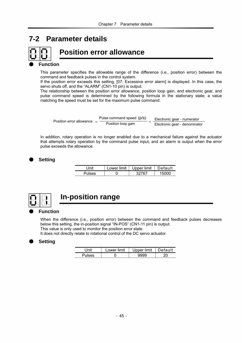
Chapter 7 Parameter details
- -
45
7-2 Parameter details
Position error allowance Function
This parameter specifies the allowable range of the difference (i.e., position error) between the command and feedback pulses in the control system. If the position error exceeds this setting, [07: Excessive error alarm] is displayed. In this case, the servo shuts off, and the “ALARM” (CN1-10 pin) is output. The relationship between the position error allowance, position loop gain, and electronic gear, and pulse command speed is determined by the following formula in the stationary state; a value matching the speed must be set for the maximum pulse command:
In addition, rotary operation is no longer enabled due to a mechanical failure against the actuator that attempts rotary operation by the command pulse input, and an alarm is output when the error pulse exceeds the allowance.
Setting Unit Lower limit Upper limit Default
Pulses 0 32767 15000
In-position range
Function When the difference (i.e., position error) between the command and feedback pulses decreases below this setting, the in-position signal “IN-POS” (CN1-11 pin) is output. This value is only used to monitor the position error state. It does not directly relate to rotational control of the DC servo actuator.
Setting Unit Lower limit Upper limit Default
Pulses 0 9999 20
Electronic gear - denominatorElectronic gear - numerator
Position loop gain Pulse command speed
Position error allowance ×= (p/s)

Chapter 7 Parameter details
- -
46
Position loop gain
Function This parameter specifies the gain of the position loop. And it determines the value based on the frictional torque and rigidity of the machine.
High setting ⇒ The position error is small, and high tracking performance to commands is obtained. If the setting is too high, the servo system will be unstable and hunting may easily occur; it should be decreased so that no hunting can occur.
Low setting ⇒ If the setting is too low, a problem may occur; for example, the tracking performance to commands may be poor, or position precision may not be obtained.
When no hunting occurs and neither overshoot nor undershoot occurs, set the maximum gain.
Setting
Unit Lower limit Upper limit Default s-1 10 9999 Note
Note: The actual setting varies with the DC servo actuator model. When changing the value,
consider the defaults shown in Section 7-1, "Default parameters" as the standard (guide setting).
Speed loop proportional gain
Function This parameter specifies the proportional gain of the speed loop. Determine the value based on the moment of inertia, the frictional torque, and the rigidity of the machine.
High setting ⇒ If the setting is too high, the servo system will be unstable (hunting) and overshoot will easily occur.
Low setting ⇒ If the setting is too low, the responsiveness and tracking performance will be poor.
When no hunting occurs and neither overshoot nor undershoot occurs, set the maximum gain.
Setting Unit Lower limit Upper limit Default - 10 9999 Note
Note: The actual setting varies with the DC servo actuator model. When changing the value,
consider the defaults shown in “Section 7-1, Default parameters" as the standard (guide setting).
Overshoot
Optimal Undershoot
Speed
Time

Chapter 7 Parameter details
- -
47
Speed loop integral gain
Function This parameter specifies the speed loop integral gain.
High setting ⇒ If the setting is too high, the servo system will be unstable (hunting) and overshoot will easily occur.
Low setting ⇒ If the setting is too low, the responsiveness and tracking performance will be poor.
Setting Unit Lower limit Upper limit Default - 0 9999 Note
Note: The actual setting varies with the DC servo actuator model. When changing the value,
consider the defaults shown in “Section 7-1, Default parameters" as the standard (guide setting).
Speed loop action gain
Function This parameter specifies the speed loop action gain. Generally, set this factor 0.
High setting ⇒ If the setting is too high, the servo system will be unstable (hunting) and overshoot will easily occur.
Setting Unit Lower limit Upper limit Default - 0 9999 0
Speed feed forward factor
Function This parameter specifies the factor used to give the first-order derivative value to a speed command. Usually set this factor to 0. This setting is usually required to improve the speed.
Setting Unit Lower limit Upper limit Default - 0 9999 0

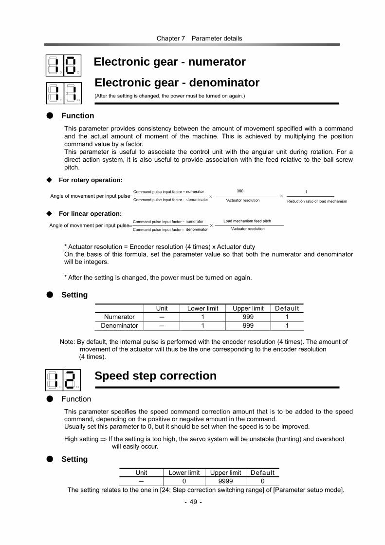
Chapter 7 Parameter details
- -
49
Electronic gear - numerator
Electronic gear - denominator
(After the setting is changed, the power must be turned on again.)
Function This parameter provides consistency between the amount of movement specified with a command and the actual amount of moment of the machine. This is achieved by multiplying the position command value by a factor. This parameter is useful to associate the control unit with the angular unit during rotation. For a direct action system, it is also useful to provide association with the feed relative to the ball screw pitch.
For rotary operation:
For linear operation:
* Actuator resolution = Encoder resolution (4 times) x Actuator duty On the basis of this formula, set the parameter value so that both the numerator and denominator will be integers. * After the setting is changed, the power must be turned on again.
Setting Unit Lower limit Upper limit Default
Numerator - 1 999 1 Denominator - 1 999 1
Note: By default, the internal pulse is performed with the encoder resolution (4 times). The amount of
movement of the actuator will thus be the one corresponding to the encoder resolution (4 times).
Speed step correction
Function This parameter specifies the speed command correction amount that is to be added to the speed command, depending on the positive or negative amount in the command. Usually set this parameter to 0, but it should be set when the speed is to be improved. High setting ⇒ If the setting is too high, the servo system will be unstable (hunting) and overshoot
will easily occur.
Setting Unit Lower limit Upper limit Default - 0 9999 0
The setting relates to the one in [24: Step correction switching range] of [Parameter setup mode].
× denominatorCommand pulse input factor
numeratorCommand pulse input factor --
360 1 ×=
*Actuator resolution Reduction ratio of load mechanism Angle of movement per input pulse
Load mechanism feed pitch ×= *Actuator resolution
Angle of movement per input pulse denominatorCommand pulse input factor
numeratorCommand pulse input factor --

Chapter 7 Parameter details
- -
50
Torque step correction
Function This parameter specifies the torque command correction amount that is to be added to the torque command, depending on the positive or negative amount in the command. Usually set this parameter to 0, but it should be set when the speed is to be improved.
High setting ⇒ If the setting is too high, the servo system will be unstable (hunting) and overshoot will easily occur.
Setting Unit Lower limit Upper limit Default - 0 9999 0
The setting relates to the one in [24: Step correction switching range] of [Parameter setup mode].
Forward torque limit
Reverse torque limit
Function This parameter specifies the maximum value of the forward or reverse torque with the percentage relative to the rated torque.
Setting Unit Lower limit Upper limit Default % 0 Note Note
Note: The actual setting varies with the AC servo actuator model. The upper limit is calculated by
assigning to the following formula the values listed in the brochure or technical material. The rated torque is defined as 100%.
Maximum momentary torque ÷ Rated torque x 100 (%) = Lower limit (default, %)
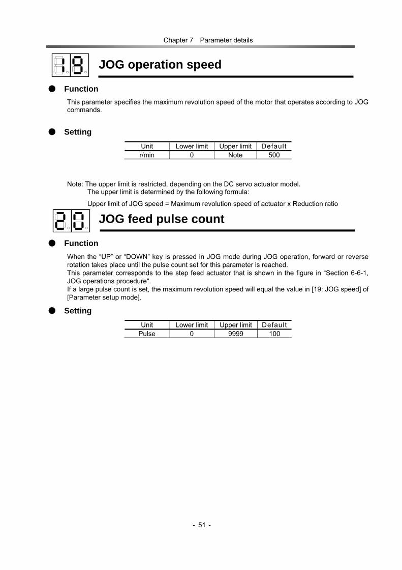
Chapter 7 Parameter details
- -
51
JOG operation speed
Function This parameter specifies the maximum revolution speed of the motor that operates according to JOG commands.
Setting
Note: The upper limit is restricted, depending on the DC servo actuator model. The upper limit is determined by the following formula:
Upper limit of JOG speed = Maximum revolution speed of actuator x Reduction ratio
JOG feed pulse count
Function When the “UP” or “DOWN” key is pressed in JOG mode during JOG operation, forward or reverse rotation takes place until the pulse count set for this parameter is reached. This parameter corresponds to the step feed actuator that is shown in the figure in “Section 6-6-1, JOG operations procedure". If a large pulse count is set, the maximum revolution speed will equal the value in [19: JOG speed] of [Parameter setup mode].
Setting Unit Lower limit Upper limit Default
Pulse 0 9999 100
Unit Lower limit Upper limit Default r/min 0 Note 500

Chapter 7 Parameter details
- -
52
2nd position loop gain
Function A position loop gain that functions when the cumulative number of pulses in the deviation counter falls below the pulse number set by “Parameter setting mode” → “24: “2nd control switching range.”
Setting Unit Lower limit Upper limit Default S-1 10 9999 Note
Note: Setting of this parameter is not required for servo operations under normal operating conditions.
Setting is sometimes effective for applications that require enhanced controllability. his function does not operate if the value in “Parameter” → “24: “2nd control switching range” is “0.” Be certain to consult the HarmonicDrive System sales office about a set value when a value other than “0” is set to enable this function.
2nd Speed loop proportional gain
Function A speed loop proportional gain that functions when the cumulative number of pulses in the deviation counter falls below the pulse number set by “Parameter setting mode” → “24: “2nd control switching range.”
Setting Unit Lower limit Upper limit Default - 10 9999 Note
Note:Setting of this parameter is not required for servo operations under normal operating conditions.
Setting is sometimes effective for applications that require enhanced controllability. This function does not operate if the value in “Parameter”→ “24: “2nd control switching range” is “0.” Be certain to consult the Harmonic Drive System sales office about a set value when
a value other than “0” is set to enable this function.
2nd Speed loop integral gain
Function A speed loop integral gain that functions when the cumulative number of pulses in the deviation counter falls below the pulse number set by “Parameter setting mode” → 24: “2nd control switching range.”
Setting Unit Lower limit Upper limit Default - 0 9999 Note
Note: Setting of this parameter is not required for servo operations under normal operating conditions.
Setting is sometimes effective for applications that require enhanced controllability. This function does not operate if the value in “Parameter” → 24: “2nd control switching range” is “0.” Be certain to consult the HarmonicDrive System sales office about a set value when a value other than “0” is set to enable this function.

Chapter 7 Parameter details
- -
53
2nd control switching range
Function This parameter is controlled by a gain set by “Parameter setting mode” → 21: “2nd position loop gain,” 22: “2nd speed lop proportional gain” and 23 “2nd speed loop integral gain” when the cumulative number of pulses in the deviation counter falls below the pulse number set here.
Setting Unit Lower limit Upper limit Default
Pulse 0 9999 0
Note: Use this parameter as it is set to “0” for operations under normal operating conditions. Be certain to consult the HarmonicDrive System sales office before changing this parameter when a change seems necessary.
Control input filter time constant
Function This parameter specifies the time constant of the soft low pass filter to be applied to control input terminal signals other than forward and reverse command pulses. If the driver is used in an environment where external high-frequency noise is generated, the control input signals may experience interference.
Setting Unit Lower limit Upper limit Default ms 0 99 0
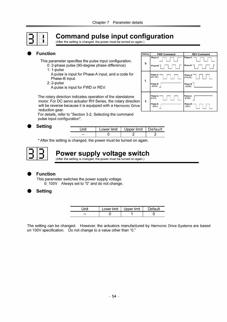
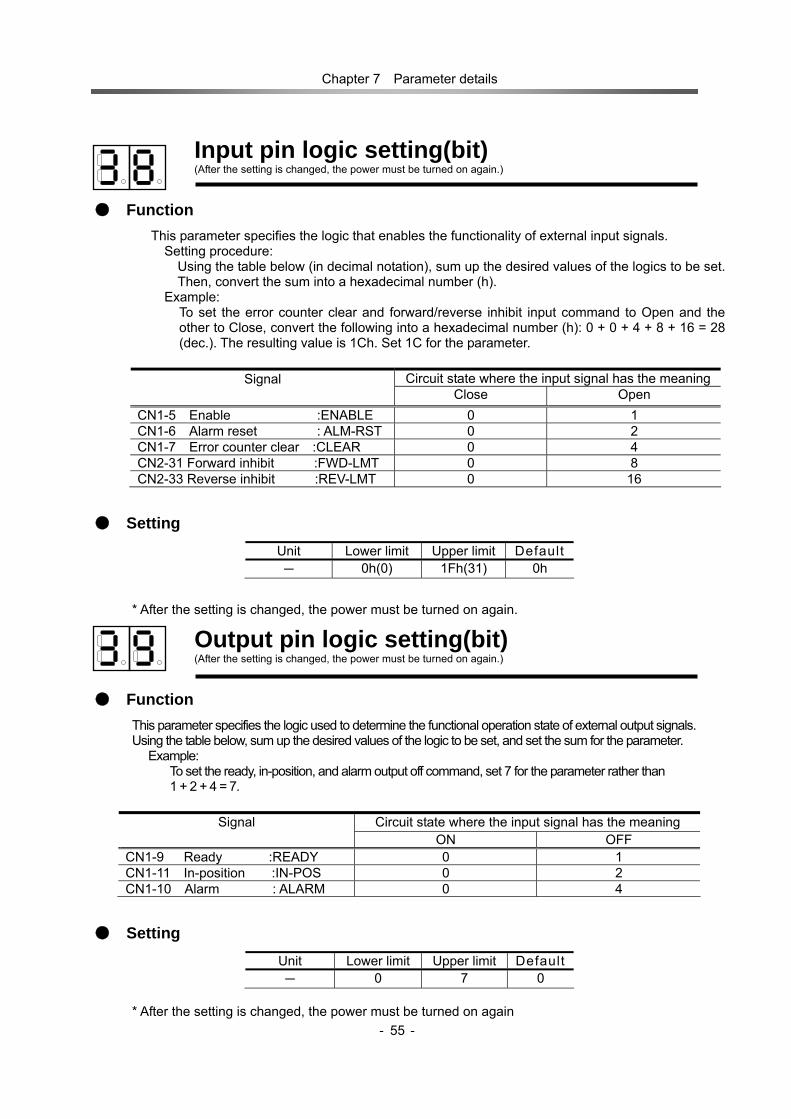
Chapter 7 Parameter details
- -
55
Input pin logic setting(bit) (After the setting is changed, the power must be turned on again.)
Function This parameter specifies the logic that enables the functionality of external input signals.
Setting procedure: Using the table below (in decimal notation), sum up the desired values of the logics to be set. Then, convert the sum into a hexadecimal number (h).
Example: To set the error counter clear and forward/reverse inhibit input command to Open and the other to Close, convert the following into a hexadecimal number (h): 0 + 0 + 4 + 8 + 16 = 28 (dec.). The resulting value is 1Ch. Set 1C for the parameter.
Circuit state where the input signal has the meaningSignal Close Open
CN1-5 Enable :ENABLE 0 1 CN1-6 Alarm reset : ALM-RST 0 2 CN1-7 Error counter clear :CLEAR 0 4 CN2-31 Forward inhibit :FWD-LMT 0 8 CN2-33 Reverse inhibit :REV-LMT 0 16
Setting Unit Lower limit Upper limit Default - 0h(0) 1Fh(31) 0h
* After the setting is changed, the power must be turned on again.
Output pin logic setting(bit) (After the setting is changed, the power must be turned on again.)
Function This parameter specifies the logic used to determine the functional operation state of external output signals. Using the table below, sum up the desired values of the logic to be set, and set the sum for the parameter.
Example: To set the ready, in-position, and alarm output off command, set 7 for the parameter rather than 1 + 2 + 4 = 7.
Circuit state where the input signal has the meaning Signal ON OFF
CN1-9 Ready :READY 0 1 CN1-11 In-position :IN-POS 0 2 CN1-10 Alarm : ALARM 0 4
Setting Unit Lower limit Upper limit Default - 0 7 0
* After the setting is changed, the power must be turned on again

Chapter 7 Parameter details
- -
56
JOG acceleration/deceleration time constant
Function This parameter specifies the acceleration/deceleration time that is needed to reach 3,000r/min with the JOG motor shaft.
Setting Unit Lower limit Upper limit Default ms 1 9999 100
CLEAR signal function selection
Function This parameter specifies the input signal with which one, to clear the error counter.
0: Clears the error counter when the CLEAR signal is input. 1: Clears the error counter when the ALM-RST or ENABLE signal is input.
Setting Unit Lower limit Upper limit Default - 0 1 1
Note: Setting this parameter to 1 disables the function of the error counter input signal [CN1-7: CLEAR].
Multiplication of 2-phase pulse (After the setting is changed, the power must be turned on again.)
Function This parameter is available also when 0 is set for [31: Command configuration] of [Parameter setup mode] (selecting of 2-phase pulse train).
1: 1 time 2: 2 times 4: 4 times
Setting Unit Lower limit Upper limit Default - 1 4 4
* After the setting is changed, the power must be turned on again
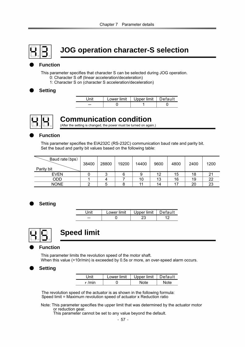
Chapter 7 Parameter details
- -
57
JOG operation character-S selection
Function This parameter specifies that character S can be selected during JOG operation.
0: Character S off (linear acceleration/deceleration) 1: Character S on (character S acceleration/deceleration)
Setting Unit Lower limit Upper limit Default - 0 1 0
Communication condition (After the setting is changed, the power must be turned on again.)
Function This parameter specifies the EIA232C (RS-232C) communication baud rate and parity bit. Set the baud and parity bit values based on the following table:
Baud rate(bps) Parity bit
38400 28800 19200 14400 9600 4800 2400 1200
EVEN 0 3 6 9 12 15 18 21 ODD 1 4 7 10 13 16 19 22
NONE 2 5 8 11 14 17 20 23
Setting Unit Lower limit Upper limit Default - 0 23 12
Speed limit
Function This parameter limits the revolution speed of the motor shaft. When this value (+10r/min) is exceeded by 0.5s or more, an over-speed alarm occurs.
Setting Unit Lower limit Upper limit Default
r/min 0 Note Note
The revolution speed of the actuator is as shown in the following formula: Speed limit = Maximum revolution speed of actuator x Reduction ratio
Note: This parameter specifies the upper limit that was determined by the actuator motor
or reduction gear. This parameter cannot be set to any value beyond the default.

Chapter 7 Parameter details
- -
58
Dynamic brake on/off
Function This parameter specifies whether or not the dynamic brake should be when an alarm occurs, operated with the servo-off.
0: If the servo is turned on once in the on state, when the driver is powered on. After this, the brake does not operate.
1: The brake operates when either the driver is powered on or an alarm occurs. 2: The brake operates when either the driver is powered on or the servo is turned off.
* When the driver is powered off, the dynamic brake is always in operation.
Setting Unit Lower limit Upper limit Default - 0 2 1
Regeneration brake on/off
Function If this parameter is set on, input of a servo-on signal causes an emergency stop according to the driver control (regeneration brake), and the servo is turned off after it stops. If this parameter is set off, input of a servo-on signal causes an immediate servo-off according to the driver control, and the motor is left free.
0: Does not operate the regeneration brake. 1: Operates the regeneration brake.
Setting Unit Lower limit Upper limit Default - 0 1 0

Chapter 8 Protective functions
- - 59
Chapter 8 Protective functions 8-1 Outline of protective functions The HS-360 driver contains various functions that protect the alarm and driver from abnormal circumstances. When one of them operates, the actuator driving stops and a two-digit alarm code is displayed in the display panel segment. When an alarm occurs, an external output [ALARM] signal is output with the motor placed in the servo-off state. An emergency stop may occur, or the servo-free mode may be entered, depending on the setting of parameter No. 46 [Dynamic brake on/off].
Alarm code Alarm name Description of detection Alarm clear
00 Memory failure
Indicates that an attempt to read or write data for EEPROM resulted in failure.
Impossible
01 Overload Indicates that the motor remains overloaded with its electronic thermal detector.
Possible
02 Encoder failure
Indicates that cable disconnection of the motor encoder was detected.
Impossible
03 Regeneration failure
Indicates that over supply voltage was detected. Impossible
04 Overheat Indicates that the temperature of the driver's radiator plate exceeded the allowable temperature (75°C).
Possible
05 CPU failure Indicates that the system has operated abnormally due to an unknown cause.
Impossible
06 Over-current Indicates that motor current exceeding the predetermined level flowed for 1ms or longer.
Impossible
07 Excessive error
Indicates that the amount of accumulated pulses for command pulses exceeded the parameter error limit.
Possible
09 IPM failure Indicates that the IPM does not operate normally. Impossible
12 Over-speed Indicates that the revolution speed of the motor exceeded the speed limit plus 10rpm for 0.5s or longer.
Possible
Below are details of the causes of alarms and actions against them.
Note: If any alarm is indicated as "Alarm clear: Impossible", turn off the power first of all before taking action against the alarm. After the cause of the alarm has been resolved, turn on the power again.
In addition, if the driver system can no longer continue control due to noise or another cause, the display blinks, as follows, in the LED display segment on the front of the body: All operations are disabled, and alarm signal output does not take place at this time. Remove the cause of the alarm, and then power on the driver. If the alarm is not yet reset, contact a business office of Harmonic Drive Systems.
1. During troubleshooting, do not perform wiring with power on. Before beginning wiring, be sure to power off the driver.
2. Clear up objects around the equipment. In particular, make a careful
inspection to ensure that no extra objects (e.g., chips of wires, tools) remain in the equipment.
3. If two or more persons are working with the equipment, before powering it on
make arrangements to bear mutual safety in mind. Warning

Chapter 8 Protective functions
- - 60
8-2 Details of protective functions
Memory failure (Alarm clear: Impossible)
Description This function indicates that an alarm has occurred due to driver EEPROM memory failure. This alarm cannot be reset.
Possible causes (1) If the alarm occurs when the power is turned on:
Cause 1: Failure in HS-360 driver control circuit ⇒ Action: Contact a business office of Harmonic Drive Systems. (Replacing the HS-360 driver)
(2) If the alarm occurs during operation: Cause 1: A device of the HS-360 driver control circuit malfunctioned. ⇒ Action: Contact a service department or a business office of Harmonic Drive Systems. (Replacing the HS-360 driver)
In addition, check whether there is any improper point regarding the ambient conditions for the location of instruction. Do this according to the instructions in “Section 4-3, Location and installing”.
Overload (Alarm clear: Possible)
Description
This function continuously monitors the motor current. When both the current and the time applied exceed the curve shown in the figure, this function causes an overload alarm to occur.
For example,
(1)When a current of approximately 1.2-times the actuator rated current is generated for a long time, the alarm occurs.
(2) When a current of approximately 3-times the actuator rated current is generated for approximately 20s, the alarm occurs.
Possible causes (1) If alarm occurs when the power
is turned on: Cause 1: A device of the HS-360
driver control circuit malfunctioned. ⇒Action: Contact a service department
or a business office of Harmonic Drive Systems. (Replacing the HS-360 driver)
1000
100
10
Ope
ratio
n tim
e(s)
Current carrying capacity (Maximum current)
Actuator current
×1 ×2 ×3
Approximately 1.2 times rated current
Overload area
Chapter 8 Protective functions
- - 61
(2) If the alarm occurs when the servo is powered on: Cause 1: The encoder connector (CN2) is not connected. ⇒ Action: Check whether the encoder connector (CN2) is connected properly.
(3) If the alarm occurs during operation of overload with the actuator:
Cause 1: Overloaded operation ⇒ Action: Reconsider the effective duty ratio of the actuator to decrease it.
(4) If the alarm occurs after the actuator continues hunting:
Cause 1: Hunting phenomenon occurs due to defect of gain adjustment ⇒ Action: Make the following adjustments so that the actuator matches the load:
[Parameter setup mode] → [02: Position loop gain], [03: Speed loop proportion gain], [04: Speed loop integral gain], and [05: Speed loop derivative gain].
(5) If the alarm occurs when the actuator is in standalone mode (no load):
Cause 1: The motor or encoder is connected incorrectly ⇒ Action: Correct the connection according to the instructions in “Chapter 4, Installing the
HS-360 driver”.
Encoder failure (Alarm clear: Impossible)
Description
This alarm occurs when the signal from the encoder stops. The only way to reset it is to examine the cause, and shut off and then turn on the power.
Possible causes (1) If the alarm occurs when the power is turned on:
Cause 1: The encoder connector (CN2) is not connected, or the connection is faulty or disconnected.
⇒ Action: Reconnect the CN2 connector firmly, or check the wiring. Cause 2: Noise is included on the encoder cable. ⇒ Action: Check whether the connection of the encoder cable shielded wire is separated,
and whether both the actuator and driver are grounded. Cause 3: A component in the encoder broke, or the driver is broken. ⇒ Action: Contact a business office of Harmonic Drive Systems.
(Replacing the actuator or driver) (2) If the alarm occurs during operation: (normally restored by cooling the actuator)
Cause 1: The encoder malfunctioned due to an actuator temperature rise. ⇒ Action: Reconsider the actuator instruction location and the cooling systems.

Chapter 8 Protective functions
- - 62
Regeneration failure (Alarm clear: Impossible)
Description This alarm occurs when an over power supply voltage is detected. The only way to reset it is to examine the cause, and shut off and then turn on the power.
Possible causes (1) If the alarm occurs during deceleration:
Cause 1: The ambient conditions of operation are severe. ⇒ Action: Recheck that the ambient conditions are not problematic in terms of the
specifications. (Increase the acceleration/deceleration time or quiescent time, if required) Cause 2: Insufficient capacity of regeneration ⇒ Action: A regeneration unit needs to be added.
Refer to “Section 10-6, Regeneration unit”, and reconsider this action.
Overheat (Alarm clear: Possible)
Description
This alarm occurs when the temperature of the HS-360 driver radiator plate exceeds the allowable temperature (75°C). After the temperature decreases below the operation detection temperature, reset the alarm or power on the driver again.
Possible causes (1) If the alarm occurs when the power is turned on:
Cause 1: HS-360 driver control circuit failure ⇒ Action: Contact a business office of Harmonic Drive Systems.
(Replacing the HS-360 driver) (2) If the alarm occurs during operation (the operation can resume after a lapse
of 4 to 5 min): Cause 1: Overloaded operation ⇒ Action: Reconsider the effective duty ratio of the actuator to decrease it. Cause 2: The ambient temperature of the HS-360 driver is higher than 50°C. ⇒ Action: Reconsider the actuator instruction location and the cooling system.
Pay sufficient attention to operation when rotating the actuator from the load side. If the driver is operated while the alarm is rotated from
the load side, the driver may burn. Warning

Chapter 8 Protective functions
- - 63
CPU failure (Alarm clear: Impossible)
Description This alarm occurs due to a driver CPU failure. It cannot be reset.
Possible causes (1) If the alarm occurs when the power is turned on:
Cause 1: While the actuator is rotating, the driver is powered on due to an unknown cause.
⇒ Action: Configure the system so that the actuator cannot rotate when the driver is powered on.
Cause 2: HS-360 driver control circuit failure ⇒ Action: Contact a business office of Harmonic Drive Systems.
(Replacing the HS-360 driver) (2) If the alarm occurs during operation:
Cause 1: Malfunction caused by external noise ⇒ Action: Suppress the noise according to the instructions in “Section 4-4, Suppressing
noise”. Cause 2: HS-360 driver control circuit failure ⇒ Action: Contact a business office of Harmonic Drive Systems.
(Replacing the HS-360 driver)
Over-current (Alarm clear: Impossible)
Description
This alarm occurs when the maximum current, depending on the DC servo actuator model, is detected for 1ms or longer. The only way to reset it is to examine the cause, and shut off and then turn on the power.
Possible causes (1) If the alarm occurs when the power is turned on:
Cause 1: HS-360 driver control circuit failure ⇒ Action: Contact a business office of Harmonic Drive Systems.
(Replacing the HS-360 driver) (2) If the alarm occurs when the input signal [CN1-5: S-ON] is input (ON):
Cause 1: HS-360 driver control circuit failure ⇒ Action: Contact a business office of Harmonic Drive Systems.
(Replacing the HS-360 driver)

Chapter 8 Protective functions
- - 64
(3) If the alarm occurs when the input signal [CN1-5: ENABLE] is input (ON), but normal operation is restored by removing the motor cables (+,-):
Cause 1: Motor cable short circuit ⇒ Action: Inspect and reconnect or replace/repair the motor cables. Cause 2: Motor winding short circuit ⇒ Action: Contact a business office of Harmonic Drive Systems.
(Replacing the actuator) (4) If the alarm occurs during acceleration or deceleration:
Cause 1: Excessive moment of inertia of load and excessively short acceleration/deceleration time
⇒ Action: Decrease the moment of inertia of load. Cause 2: The gain is too high or low. ⇒ Action: Make the following adjustments according to the load: [Parameter setup mode]
→ [02: Position loop gain], [03: Speed loop proportion gain], [04: Speed loop integral gain], and [05: Speed loop derivative gain].
Excessive error (Alarm clear: Possible)
Description
This alarm occurs when the error counter value reaches or exceeds the pulse count being set for [00: Transmission error allowance] of [Parameter setup mode]. It can be reset by inputting the signal to [CN1-7 Error counter clear: CLEAR] or [CN1-6 Alarm reset: ALM-RST]. The error counter is also cleared at the same time.
Possible causes (1) If the alarm occurs when the power is turned on:
Cause 1: HS-360 driver control circuit failure ⇒ Action: Contact a business office of Harmonic Drive Systems.
(Replacing the HS-360 driver) (2) If the alarm occurs during acceleration or deceleration:
Cause 1: Excessive moment of inertia of load ⇒ Action1: Try to decrease the moment of inertia of the load. ⇒ Action2: Increase or decrease the command pulse frequency of the higher-level
system. Cause 2: The [Area of excessive error] or [Gain] value of [Parameters] is too small. ⇒ Action: Extend [Area of excessive error]. Alternatively, make the following adjustments
according to the load: [Parameter mode] → [02: Position loop gain], [03: Speed loop proportion gain], [04: Speed loop integral gain], and [05: Speed loop derivative gain].
Cause 3: [Command pulse frequency] is too large. ⇒ Action: Decrease the [Command output pulse frequency] setting of the higher-level
system.

Chapter 8 Protective functions
- - 65
(3) If the speed does not increase according to the command and the alarm occurs after a while:
Cause 1: One or more encoder or motor cables are disconnected. ⇒ Action: Check whether the encoder and motor cable are connected properly.
(4) If the alarm occurs due to a failure in the external mechanical system:
Cause 1: A mechanical-system failure disabled the rotation of the actuator, which attempted to perform the rotation in response to the command pulse input. As a result, the error pulse exceeded the allowance.
⇒ Action: Remove the obstacle from the mechanical system.
IPM failure (Alarm clear: Impossible)
Description This alarm occurs when the IPM does not operate normally. The only way to reset it is to turn on the power.
Possible causes (1) If the alarm occurs when the power is turned on:
Cause 1: A motor wire has been earth fault. ⇒ Action: Ensure that motor wires are not earth fault. Cause 2: HS-360 driver circuit failure ⇒ Action: Contact a business office of Harmonic Drive Systems.
(Replacing the HS-360 driver) (2) If the alarm occurs during operation:
Cause 1: A device of the HS-360 driver control circuit malfunctioned. ⇒ Action: Contact a business office of Harmonic Drive Systems.
(Replacing the HS-360 driver)
In addition, check whether the ambient conditions of the instruction location contain no inappropriate point. Do this according to the instructions in “Section 4-3, Location and installing”.
Cause 2: Short circuit of actuator motor winding ⇒ Action: Contact a business office of Harmonic Drive Systems. (Replacing the actuator)

Chapter 8 Protective functions
- - 66
Over-speed (Alarm clear: Possible)
Description
The alarm occurs when the motor revolution speed exceeds the motor speed limit plus 10r/min for 0.5s. This alarm can be reset.
Possible causes (1) If the alarm occurs when the power is turned on:
Cause 1: The forcible rotation to the actuator output shaft is faulty. ⇒ Action: If the rotation takes place with the external force applied to the actuator output
shaft, modify the equipment so that this rotation cannot take place. Cause 2: Disconnection or wiring failure of encoder cable ⇒ Action: Check the encoder cables and their wiring. Cause 3: HS-360 driver control circuit failure ⇒ Action: Contact a business office of Harmonic Drive Systems.
(Replacing the HS-360 driver) (2) If the alarm occurs when input of a rotation command causes high-speed
rotation of the actuator: Cause 1: Rapid raising of [Command pulse frequency] ⇒ Action: Set an earlier raising time point. Cause 2: Large overshoot caused by improper gain adjustmen
Make the following adjustments so that the raising time matches the load: [Parameter setup mode] → [02: Position loop gain], [03: Speed loop proportion gain], [04: Speed loop integral gain], and [05: Speed loop derivative gain].

Chapter Troubleshooting procedure and action
- 67 -
Chapter 9 Troubleshooting procedure and action
This chapter details the troubleshooting procedure and action flow for actuator operation failures other than the alarms. It consists of the following sections:
9-1 No rotation 9-2 Unusable rotation 9-3 Poor positioning accuracy
Note: In the flowcharts, "Y" and "N" represent "Yes" and "No", respectively.
9-1 No rotation of actuators
Start
Is the front panel LED on?
Is the powernormal?
Are NFB and MS on?
・Power failure ・NFB or MS failure ・Wrong wiring
N N Y
Is MS open with power on sequence?
N
Driver failure
Y
Recover power after removing the cause.
Y
Turn on NFB and MS.Is an alarm indicated?
Refer to Section 8-2, "Protective functions".
Y
N
Y
Note: NFB: No fuse breaker MS: Main power switch
N
Is CN1-5 ENABLE being input?
Input ENABLE. N
Y Is CN2-31 FWD-LIMor CN2-33 REV-LMT in operation?
Deactivate FWD-LIM or REV-LMT.
Y
N
Is acommand pulse comingin?
Input command pulse.N
Y Is the command configuration correct?
Make the higher-level system setting identical with [31: Command configuration selection] of [Parameter setup mode].
N
Y
To next page

Chapter Troubleshooting procedure and action
- 68 -
9-2 Unstable rotation of actuator
N
Are motor wire connection screws loose? Is the motor wire disconnected?
Check motor cable connection.
Y
N
Y Actuator fault
Is the actuator shaft locked? Y Unlock the actuator
shaft.
N
Actuator fault
Is CN1-7 CLEAR sometimes being input?
Shut off CN1-7 CLEAR
N
Y
Previous
Is the power supply voltage normal?
Apply the proper voltage.N
Is the power supply voltage fluctuation within its allowance?
Check the power capacity, input capacity, etc.
Y
N Y
Start
To next page
Is the temperature in the panel normal?
Examine the heating elements in panel, and consider the cooling system.
N
Y
Motor rare short-circuited? Is the motor grounded?
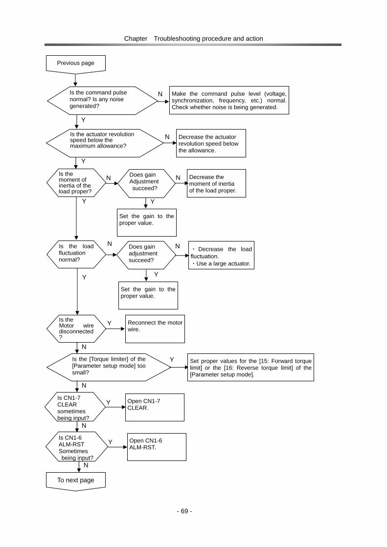
Chapter Troubleshooting procedure and action
- 69 -
Previous page
Is the command pulse normal? Is any noise generated?
Make the command pulse level (voltage, synchronization, frequency, etc.) normal. Check whether noise is being generated.
N
Y
Is the actuator revolution speed below the maximum allowance?
Decrease the actuator revolution speed below the allowance.
N
Y
Set the gain to the proper value.
Is the load fluctuation normal?
・ Decrease the load fluctuation. ・Use a large actuator.
N
Y
Does gain adjustment succeed?
N
Y
Set the gain to the proper value.
Y Is the Motor wiredisconnected?
Reconnect the motor wire.
N
YIs the [Torque limiter] of the [Parameter setup mode] too small?
Set proper values for the [15: Forward torque limit] or the [16: Reverse torque limit] of the [Parameter setup mode].
N
Y Is CN1-7 CLEAR sometimes being input?
Open CN1-7 CLEAR.
N
To next page
Is the moment of inertia of the load proper?
Decrease the moment of inertia of the load proper.
N
Y
Does gain Adjustment succeed?
N
Y Is CN1-6 ALM-RST Sometimes being input?
Open CN1-6 ALM-RST.
N
Y

Chapter Troubleshooting procedure and action
- 70 -
9-3 Poor positioning accuracy
N Is the Encoder signal normal?
Securely shield and ground the encoder cable.
Y
Previous page
N
Is there anoise included in the encoder signal?
Y
Replace the actuator.
Y Does rattle or
resonance occur inthe mechanical system?
N
Improve the mechanical system.
Replace the actuator or driver.
Is the higher levelsystem programnormal?
Amend the program.N
Is the command pulse normal?
Correct the pulse count. Check the noise.
Y
N
Y
Start
To next page
Is the command pulse timing normal?
Reconsider the Command pulse circuit.
Y
N
Is the electronic gear valid?
Correct the electronic gear value.
N

Chapter Troubleshooting procedure and action
- 71 -
Is the moment of inertia of the load proper?
Decrease the moment of inertia of the load.
N
Y
Previous page
Does gain adjustment succeed?
N
Y
Correct the gain properly.
NDoes rattle or resonance occur n the mechanical system?
Y
Improve the mechanical system.
Replace the actuator or driver.

DC servo drover HS-360 Series
- 72-
INDEX 1 pulse train ··············································· 11,54 2-pulse train ······································· 11,19,20,54 Multiplication of 2-phase pulse····················· 44,56 2-phase pulse train ································· 11,54,56 A-B phase pulses with 90-degree difference····· 11 A⋅A ······································································ 8 ALARM ··········································· 7,16,40,55,59 ALM-RST ·················································· 7,13,54 Phase-A input ····················································· 8 Phase-A reversal input········································ 8 B・B ······························································ 8,18 Phase-B input ····················································· 8 Phase-B reversal input········································ 8 CLEAR················································· 7,13,40,55 CLEAR signal function selection ·················· 44,56 CN1·············································· 5,7,10,12,15,30 CN2··················································· 6,8,17,18,30 CN3·································································· 6,9 CN4····································································· 6 CTS································································ 9,73 DATA key ········································ 5,37,38,39,41 DOWN key················································ 5,37,38 DSR ······························································· 9,73 DTR ······························································· 9,73 E ······························································· 7,27,29 EIA232C ················································ 6,9,57,73 EGP-0V······························································· 8 EPG-Vcc ····························································· 8 FG································································· 7,8,9 FWD+························································ 7,10,11 FWD‐ ······················································ 7,10,11 FWD-LMT ············································ 8,14,40,54 FWD and REV pulse train································· 11 FWD operation pulse (+)····································· 7 FWD operation pulse (-)······································ 7 IN-COM····················································· 7,12,13 IN-POS ················································ 7,15,16,40 IPM failure···················································· 59,65 JOG operation mode···································· 36,41 JOG operation··················································· 41 JOG character-S selection······················ 42,44,57 JOG acceleration/deceleration time constant································································ 42,44,56 JOG feed pulse count ····························· 42,44,51 JOG operation speed······························ 42,44,51 LED display segment ·········································· 5 LMT-VCC ···························································· 8 LMT signal power supply ······························· 8,14 MODE key ······································ 5,36,38,39,41 MON-A ····························································· 8 MON-B································································ 8 MON-Vcc ···························································· 8 MON-0V······························································ 8 MON-Z ································································ 8 N ······························································· 7,27,28 OUT-COM······················································ 7,15 P ······························································· 7,27,28 PG-0V ···························································· 8,18 PG-VCC························································· 8,18 POS-OVR ························································· 40 POW-ON······················································ 37,40 PSF-520························································· 9,73
R································································7,27,28 READY······················································7,15,40 REV+························································· 7,10,11 REV‐ ······················································· 7,10,11 REV-LMT·········································8,14,40,51,55 REV operation pulse (+) ······································7 REV operation pulse (-) ·······································7 RS-232C-compliant ··········································6,9 RS-232C communication cable ······················9,73 RTS ·····································································9 V-ON ····························································37,40 RXD·····································································9 ENABLE ··········································7,13,37,40,54 SPD-LMT······················································37,40 T ································································7,27,28 TB···································································7,16 TB2···································································6,7 TRQ-LMT ·····················································37,40 TXD ·····································································9 UP key·······················································5,37,38 VOL-OVR ·····················································37,40 Z・Z ·······························································8,18 Z-IZ····························································7,15,16 Phase-Z input ······················································8 Phase-Z reversal input ········································8 Actuator cable ···················································29 Actuator connection terminal ····························6,7 Reset an alarm ··················································37 Alarm reset ················································7,12,13 Alarm output ··············································7,12,16 Alarm display·····················································37 Clear the alarm history ······································37 Display the alarm history ···································37 In-position··················································7,15,16 In-position range···········································44,45 Position loop gain ····································44,45,46 Operation ··························································32 Ready·····························································7,15 Encoder +5V power supply ·································8 Encoder Phase-Z ···········································7,16 Encoder failure ·············································59,61 Encoder, external power supply ··························8 Encoder, external power supply common············8 Encoder cable ···················································30 Encoder connector ······································6,8,30 Encoder power supply common ··························8 Encoder input ····················································18 Encoder monitor Phase-A output····················8,17 Encoder monitor Phase-B output ···················8,17 Encoder monitor Phase-Z output····················8,17 Encoder monitor output ··································3,17 Encoder monitor 5V power supply··················8,17 Encoder monitor power supply common ········8,17 Open collector command ·····························10,20 External dimensions ············································4 Regeneration failure ·····································59,62 Regeneration brake on/off ····························44,58 Regeneration unit connection terminal ···········7,28 Rotary direction command····························44,48 External regeneration unit connection terminal ···6 External I/O connector·································5,7,30 Over-speed···················································59,66

DC servo drover HS-360 Series
- 73-
Acceleration feed forward factor ·················· 44,48 Model ····························································· 2,21 Over-current················································· 59,63 Overheat ······················································ 59,62 Overload ······················································ 59,60 Feedback pulses count ································ 39,43 Reverse inhibit ··············································· 8,14 Reverse torque limit ····································· 44,50 Position error allowance···················· 40,43,44,45, Current speed ··················································· 39 Structure/installing procedure······························ 3 Troubleshooting ················································ 67 Circuit breaker··················································· 28 Circuit protector················································· 28 Servo on ························································ 7,13 Servo state display············································ 37 Servo parameters setup software ····················· 73 Maximum output current (rms) ···························· 3 Maximum input pulse frequency ························· 3 Trial run····························································· 32 Signal ground······················································ 9 System failure ·············································· 59,63 Effective duty ratio ············································ 39 Shutoff sequence ·············································· 31 Ambient conditions·············································· 3 Receive data ······················································· 9 Output signal common ··································· 7,15 Output pin logic setting (bit) ························· 44,55 Service temperature······································· 3,23 Impact ······························································· 23 Service humidity············································· 3,23 State display mode······································· 36,37 Service power supply·········································· 3 Serial interface···················································· 3 Serial port connector········································ 6,9 Command speed··············································· 39 Command pulse frequency ······························· 39 Cause pulse count ······································· 39,43 Command pulse input ······································· 10 Electronic gear-numerator ··························· 44,49 Electronic gear-denominator ························ 44,49 Command pulse input configuration············· 44,54 Vibration···························································· 23 Numeric monitor mode································· 36,39 Control function··················································· 3 Control output signal ··········································· 3 Control state display ···································· 39,40 Control I/O ··················································· 10,12 Control I/O connector·········································· 6 Control I/O signal ················································ 3 Control input filter time constant··················· 44,53 Control method ··················································· 3 Forward inhibit ··············································· 8,14 Forward torque limit ····································· 44,50 Isolation transformer ···································· 28,74 Connector ···················································· 28,72 Grounding terminal ····································· 6,7,29 Installing······················································· 23,24 Grounding ························································· 24 Ground wire cable········································ 27,29 Location ···························································· 23 Operations ························································ 32 Transmit data ······················································ 9 Request to transmit············································· 9 Speed step correction ·································· 44,49 Speed limit ··················································· 44,57
Speed feed forward factor ····························44,47 Speed loop integral gain·······························44,47 Speed loop derivative gain ···························44,47 Speed loop proportional gain························44,46 2nd Position loop gain ··································44,53 2nd Speed loop proportional gain·················44,53 2nd speed loop integral gain ························44,53 2nd Control switching range·························44,53 Dynamic brake on/off·······························13,44,58 Data Set Ready ···················································9 Data Terminal Ready ···········································9 Charge voltage monitor ··································5,34 Clear to send ·······················································9 Communication condition setting··················44,57 Rated output current (rms) ··································3 Stop cause display ·······································39,40 Applicable position sensor···································3 Power supply terminal ······································6,7 Power cable·······················································27 Power supply voltage ·····························22、44,54 Power on sequence···········································31 Power loss·························································23 Accessories ·······················································21 Torque command filter ··································44,48 Torque command···············································39 Torque step correction··································44,50 Torque peak·······················································39 Built-in circuit ·······················································3 Built-in functions ··················································3 I/O state display············································39,40 I/O signal cable··················································30 Input signal ···················································12,13 Input signal common ······································7,13 Input pin logic setting (bit) ····························44,55 Action against noise ··········································24 Noise filter ····················································25,28 Parameters························································44 Parameter setup mode·································36,38 Pulse output configuration····························19,20 Non-connection terminal ·····································7 Display panel component names ························5 Code plus pulse train·········································11 Frame ground················································7,8,9 Error counter reset ·········································7,14 Excessive error·············································59,64 Error pulse count ··········································39,43 Protective functions ········································3,59 Maintenance······················································34 Usual operation ·················································34 Nameplate ·························································21 Memory failure (EEPROM)···························59,60 Monitor ································································3 Line driver command····································10,19

The HS-360 series servo drivers are warranted as follows:
Warranty period Under the condition that the actuator are handled, used and maintained properly followed each item of the documents and the manuals, all the HS-360 series drivers are warranted against defects in workmanship and materials for the shorter period of either one year after delivery or 2,000 hours of operation time.
Warranty terms All the HS-360 series drivers are warranted against defects in workmanship and materials for the warranted period. This limited warranty does not apply to any product that has been subject to:
(1) user's misapplication, improper installation, inadequate maintenance, or misuse.
(2) disassembling, modification or repair by others than Harmonic Drive Systems, Inc.
(3) imperfection caused by the other than the HS-360 servo driver.
(4) disaster or others that does not belong to the responsibility of Harmonic Drive Systems, Inc.
Our liability shall be limited exclusively to repairing or replacing the product only found by Harmonic Drive Systems, Inc. to be defective. Harmonic Drive Systems, Inc. shall not be liable for consequential damages of other equipment caused by the defective products, and shall not be liable for the incidental and consequential expenses and the labor costs for detaching and installing to the driven equipment
Warranty Period and Terms

Head Office: Believe Omori 7F 6-25-3 Minami-Ohi,Shinagawa-ku,Tokyo,Japan 140-0013 TEL +81-(0)3-5471-7800 FAX +81-(0)3-5471-7811
Overseas Division: Believe Omori 7F, 6-25-3 Minami-Ohi, Shinagawa-ku,Tokyo, Japan 140-0013 TEL +81-(0)3-5471-7800 FAX: +81-(0)3-5471-7811
Hotaka Plant:1856-1 Maki, Hotaka, Azumino-shi, Nagano, Japan 399-8305 TEL +81-(0)263-83-6800 FAX +81-(0)263-83-6901
Harmonic Drive AG:Hoenbergstrasse 14 D-65555 Limburg a.d. Lahn Germany TEL +49-6431-5008-0 FAX +49-6431-5008-18
Harmonic Drive L.L.C:247 Lynnfield Street, Peabody, MA, 01960, U.S.A. TEL 978-532-1800 FAX 978-532-9406
0703-2R-THS360-EHarmonicDrive is a registered trademark of Harmonic Drive Systems Inc.
Certified to ISO14001 (HOTAKA Plant) / ISO9001 (TÜV Management Service GmbH) All specifications and dimensions in this manual subject to change without notice.
‥