hsn 1st unit 16m q&a (1)
TRANSCRIPT

8/13/2019 HSN 1st unit 16m q&a (1)
http://slidepdf.com/reader/full/hsn-1st-unit-16m-qa-1 1/32
UNIT - I
HIGH SPEED NETWORKS (Introduction)
1. Explains the Frame relay architecture & compare it with x.25. (16)
Frame relay Networks
Frame Relay often is described as a streamlined version of X.25, offering fewer of the robust
capabilities, such as windowing and retransmission of last data that are offered in X.25.
Frame Relay Devices
Devices attached to a Frame Relay WAN fall into the following two general categories:
• Data terminal equipment (DTE) • Data circuit-terminating equipment (DCE)
DTEs generally are considered to be terminating equipment for a specific network and typically
are located on the premises of a customer. In fact, they may be owned by the customer.
Examples of DTE devices are terminals, personal computers, routers, and bridges.
DCEs are carrier-owned internetworking devices. The purpose of DCE equipment is to provide
clocking and switching services in a network, which are the devices that actually transmit data
through the WAN. In most cases, these are packet switches. Figure 10-1 shows the relationship
between the two categories of devices.
Standard Frame Relay Frame
The Five Fields Comprise the Frame Relay Frame
Each frame relay PDU consists of the following fields:
1. Flag Field. The flag is used to perform high level data link synchronization whichindicates the beginning and end of the frame with the unique pattern 01111110. To
ensure that the 01111110 pattern does not appear somewhere inside the frame, bit
stuffing and destuffing procedures are used.

8/13/2019 HSN 1st unit 16m q&a (1)
http://slidepdf.com/reader/full/hsn-1st-unit-16m-qa-1 2/32
2. Address Field. Each address field may occupy octet 2 to 3, octet 2 to 4, or octet 2 to 5,
depending on the range of the address in use. A two-octet address field comprising the
EA=ADDRESS FIELD EXTENSION BITS and the C/R=COMMAND/RESPONSEBIT.
3. DLCI-Data Link Connection Identifier Bits. The DLCI serves to identify the virtual
connection so that the receiving end knows which information connection a frame belongs to. Note that this DLCI has only local significance. A single physical channel canmultiplex several different virtual connections.
4. FECN, BECN, DE bits. These bits report congestion:
o FECN=Forward Explicit Congestion Notification bit
o BECN=Backward Explicit Congestion Notification bit
o DE=Discard Eligibility bit
5. Information Field. A system parameter defines the maximum number of data bytes that a
host can pack into a frame. Hosts may negotiate the actual maximum frame length at callset-up time. The standard specifies the maximum information field size (supportable by
any network) as at least 262 octets. Since end-to-end protocols typically operate on the
basis of larger information units, frame relay recommends that the network support themaximum value of at least 1600 octets in order to avoid the need for segmentation and
reassembling by end-users.
Frame Check Sequence (FCS) Field. Since one cannot completely ignore the bit error-rate of the
medium, each switching node needs to implement error detection to avoid wasting bandwidth
due to the transmission of erred frames. The error detection mechanism used in frame relay usesthe cyclic redundancy check (CRC) as its basis.
Congestion-Control Mechanisms
Frame Relay reduces network overhead by implementing simple congestion-notification
mechanisms rather than explicit, per-virtual-circuit flow control. Frame Relay typically isimplemented on reliable network media, so data integrity is not sacrificed because flow control
can be left to higher-layer protocols. Frame Relay implements two congestion-notification
mechanisms:
• Forward-explicit congestion notification (FECN)
• Backward-explicit congestion notification (BECN) FECN and BECN each is controlled by a
single bit contained in the Frame Relay frame header. The Frame Relay frame header also
contains a Discard Eligibility (DE) bit, which is used to identify less important traffic that can bedropped during periods of congestion.
Frame Relay versus X.25
The design of X.25 aimed to provide error-free delivery over links with high error-rates. Framerelay takes advantage of the new links with lower error-rates, enabling it to eliminate many of
the services provided by X.25. The elimination of functions and fields, combined with digital
links, enables frame relay to operate at speeds 20 times greater than X.25.
8/13/2019 HSN 1st unit 16m q&a (1)
http://slidepdf.com/reader/full/hsn-1st-unit-16m-qa-1 3/32
X.25 specifies processing at layers 1, 2 and 3 of the OSI model, while frame relay operates at
layers 1 and 2 only. This means that frame relay has significantly less processing to do at each
node, which improves throughput by an order of magnitude.
X.25 prepares and sends packets, while frame relay prepares and sends frames. X.25 packets
contain several fields used for error and flow control, none of which frame relay needs. Theframes in frame relay contain an expanded address field that enables frame relay nodes to direct
frames to their destinations with minimal processing.
X.25 has a fixed bandwidth available. It uses or wastes portions of its bandwidth as the load
dictates. Frame relay can dynamically allocate bandwidth during call setup negotiation at both
the physical and logical channel level.
2. Explain the ATM cell with a suitable diagram and explain how ATM cells are
transmitted.
Or
With a neat sketch explain the various fields of an ATM cell (NOV-DEC-2011, 10M
Or
Give the ATM cell format. Explain how ATM cells are transmitted
Asynchronous Transfer Mode (ATM) is an International Telecommunication Union-Telecommunications
Standards Section (ITU-T) standard for cell relay wherein information for multiple service types, such as
voice, video, or data, is conveyed in small, fixed-size cells. ATM networks are connection-oriented.
ATM is a cell-switching and multiplexing technology that combines the benefits of circuitswitching (guaranteed capacity and constant transmission delay) with those of packet switching
(flexibility and efficiency for intermittent traffic). It provides scalable bandwidth from a few
megabits per second (Mbps) to many gigabits per second (Gbps). Because of its asynchronousnature, ATM is more efficient than synchronous technologies, such as time-division multiplexing
(TDM).
With TDM, each user is assigned to a time slot, and no other station can send in that time slot. If
a station has much data to send, it can send only when its time slot comes up, even if all other
time slots are empty. However, if a station has nothing to transmit when its time slot comes up,
the time slot is sent empty and is wasted. Because ATM is asynchronous, time slots are availableon demand with information identifying the source of the transmission contained in the header of
each ATM cell.
ATM transfers information in fixed-size units called cells. Each cell consists of 53 octets,
or bytes. The first 5 bytes contain cell-header information, and the remaining 48 contain the payload (user information). Small, fixed-length cells are well suited to transferring voice and
video traffic because such traffic is intolerant of delays that result from having to wait for a large

8/13/2019 HSN 1st unit 16m q&a (1)
http://slidepdf.com/reader/full/hsn-1st-unit-16m-qa-1 4/32
data packet to download, among other things. Figure illustrates the basic format of an ATM cell.
Figure :An ATM Cell Consists of a Header and Payload Data
ATM Protocol architecture:
ATM is almost similar to cell relay and packets witching using X.25and frame relay like packetswitching and frame relay, ATM involves the transfer of data in discrete pieces also, like packet
switching and frame relay, ATM allows multiple logical connections to multiplexed over a single
physical interface. in the case of ATM, the information flow on each logical connection isorganised into fixed-size packets, called cells. ATM is a streamlined protocol with minimal errorand flow control capabilities :this reduces the overhead of processing ATM cells and reduces the
number of overhead bits required with each cell, thus enabling ATM to operate at high data
rates.the use of fixed-size cells simplifies the processing required at each ATM node,againsupporting the use of ATM at high data rates. The ATM architecture uses a logical model to
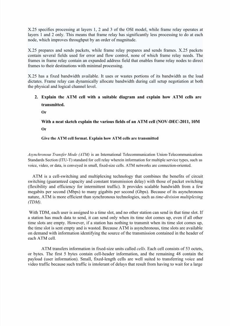
describe the functionality that it supports. ATM functionality corresponds to the physical layer
and part of the data link layer of the OSI reference model. . the protocol referencce model shown
makes reference to three separate planes:
user plane provides for user information transfer ,along with associated controls (e.g.,flow control ,error
control).
control plane performs call control and connection control functions.
management plane includes plane management ,which performs management function related
to a system as a whole and provides coordination between all the planes ,and layer management
which performs management functions relating to resource and parameters residing in its protocol entities .
The ATM reference model is composed of the following ATM layers:
• Physical layer — Analogous to the physical layer of the OSI reference model, the ATM physical layer manages the medium-dependent transmission.
• ATM layer — Combined with the ATM adaptation layer, the ATM layer is roughly
analogous to the data link layer of the OSI reference model. The ATM layer is responsible forthe simultaneous sharing of virtual circuits over a physical link (cell multiplexing) and passingcells through the ATM network (cell relay). To do this, it uses the VPI and VCI information in
the header of each ATM cell.
8/13/2019 HSN 1st unit 16m q&a (1)
http://slidepdf.com/reader/full/hsn-1st-unit-16m-qa-1 5/32
• ATM adaptation layer (AAL) — Combined with the ATM layer, the AAL is roughly
analogous to the data link layer of the OSI model. The AAL is responsible for isolating higher-
layer protocols from the details of the ATM processes. The adaptation layer prepares user datafor conversion into cells and segments the data into 48-byte cell payloads.
Finally, the higher layers residing above the AAL accept user data, arrange it into packets, andhand it to the AAL.
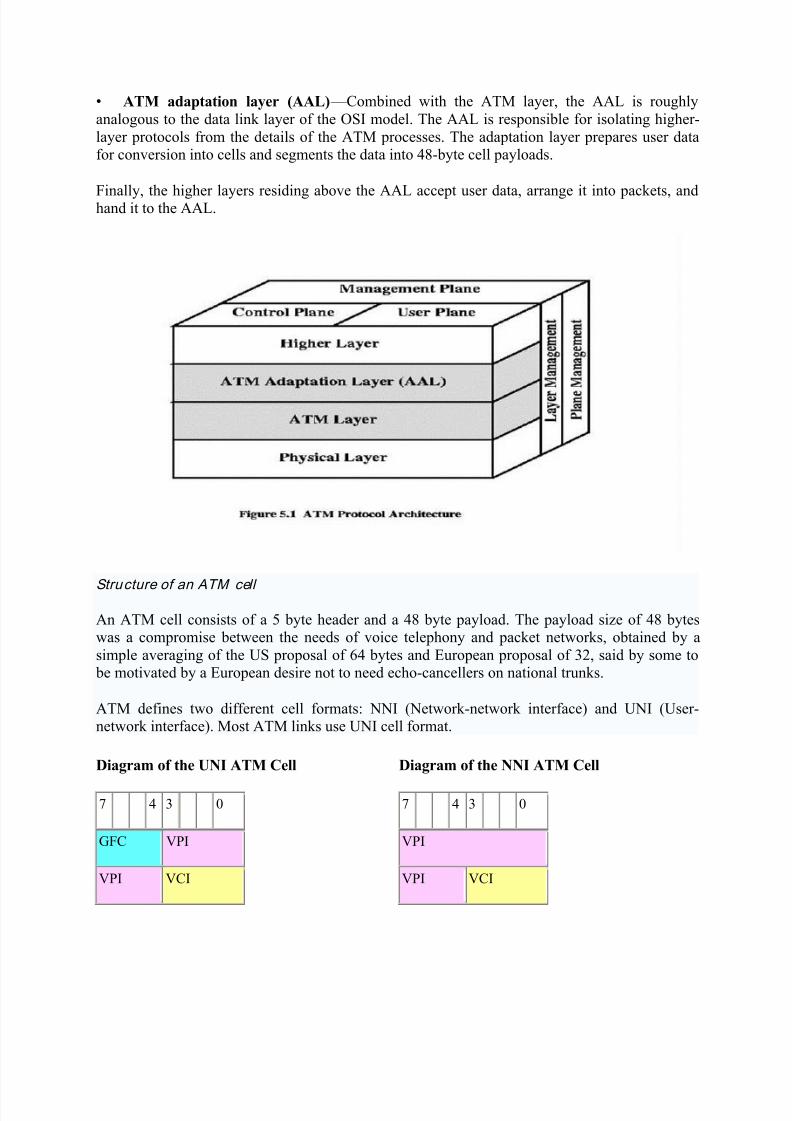
Structure of an ATM cell
An ATM cell consists of a 5 byte header and a 48 byte payload. The payload size of 48 byteswas a compromise between the needs of voice telephony and packet networks, obtained by a
simple averaging of the US proposal of 64 bytes and European proposal of 32, said by some to be motivated by a European desire not to need echo-cancellers on national trunks.
ATM defines two different cell formats: NNI (Network-network interface) and UNI (User-network interface). Most ATM links use UNI cell format.
Diagram of the UNI ATM Cell
7 4 3 0
GFC VPI
VPI VCI
Diagram of the NNI ATM Cell
7 4 3 0
VPI
VPI VCI
8/13/2019 HSN 1st unit 16m q&a (1)
http://slidepdf.com/reader/full/hsn-1st-unit-16m-qa-1 6/32
VCI
VCI PT CLP
HEC
Payload (48 bytes)
VCI
VCI PT CLP
HEC
Payload (48 bytes)
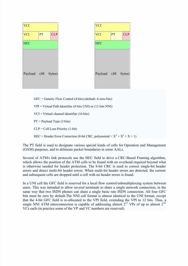
GFC = Generic Flow Control (4 bits) (default: 4-zero bits)
VPI = Virtual Path Identifier (8 bits UNI) or (12 bits NNI)
VCI = Virtual channel identifier (16 bits)
PT = Payload Type (3 bits)
CLP = Cell Loss Priority (1-bit)
HEC = Header Error Correction (8-bit CRC, polynomial = X8 + X2 + X + 1)
The PT field is used to designate various special kinds of cells for Operation and Management
(OAM) purposes, and to delineate packet boundaries in some AALs.
Several of ATM's link protocols use the HEC field to drive a CRC-Based Framing algorithm,
which allows the position of the ATM cells to be found with no overhead required beyond what
is otherwise needed for header protection. The 8-bit CRC is used to correct single-bit headererrors and detect multi-bit header errors. When multi-bit header errors are detected, the current
and subsequent cells are dropped until a cell with no header errors is found.
In a UNI cell the GFC field is reserved for a local flow control/submultiplexing system between
users. This was intended to allow several terminals to share a single network connection, in thesame way that two ISDN phones can share a single basic rate ISDN connection. All four GFC bits must be zero by default.The NNI cell format is almost identical to the UNI format, except
that the 4-bit GFC field is re-allocated to the VPI field, extending the VPI to 12 bits. Thus, a
single NNI ATM interconnection is capable of addressing almost 212
VPs of up to almost 216
VCs each (in practice some of the VP and VC numbers are reserved).

8/13/2019 HSN 1st unit 16m q&a (1)
http://slidepdf.com/reader/full/hsn-1st-unit-16m-qa-1 7/32
A Virtual Channel (VC) denotes the transport of ATM cells which have the same uniqueidentifier, called the Virtual Channel Identifier (VCI). This identifier is encoded in the cell
header. A virtual channel represents the basic means of communication between two end-points,
and is analogous to an X.25 virtual circuit.
A Virtual Path (VP) denotes the transport of ATM cells belonging to virtual channels which share a
common identifier, called the Virtual Path Identifier (VPI), which is also encoded in the cell header. Avirtual path, in other words, is a grouping of virtual channels which connect the same end-points. This
two layer approach results in improved network performance. Once a virtual path is set up, the
addition/removal of virtual channels is straightforward
Benefits of ATM
The benefits of ATM are the following:
high performance via hardware switching
dynamic bandwidth for bursty traffic
class-of-service support for multimedia
scalability in speed and network size
common LAN/WAN architecture
opportunities for simplification via VC architecture
international standards compliance
3. Explain various ATM services. (8)
Or
Discuss the various non real time ATM services (NOV-DEC-2011, 6M )
Or
What is the need for AAL in ATM networks? Draw the AAL frame format which
supports:
(1) Connection oriented data service (2) CBR services (3)VBR services

8/13/2019 HSN 1st unit 16m q&a (1)
http://slidepdf.com/reader/full/hsn-1st-unit-16m-qa-1 8/32
ATM Classes of Services
ATM is connection oriented and allows the user to specify the resources required on a per-connection basis (per SVC) dynamically. There are the five classes of service defined for ATM
(as per ATM Forum UNI 4.0 specification).
Service Class Quality of Service Parameter
constant bit rate
(CBR)
This class is used for emulating circuit switching. The cell rate is constant
with time. CBR applications are quite sensitive to cell-delay variation.
Examples of applications that can use CBR are telephone traffic (i.e., nx64
kbps), videoconferencing, and television.
variable bit rate –
non-real time
(VBR – NRT)
This class allows users to send traffic at a rate that varies with time
depending on the availability of user information. Statistical multiplexing is provided to make optimum use of network resources. Multimedia e-mail is an
example of VBR – NRT.
variable bit rate –
real time (VBR –
RT)
This class is similar to VBR – NRT but is designed for applications that are
sensitive to cell-delay variation. Examples for real-time VBR are voice with
speech activity detection (SAD) and interactive compressed video.
available bit rate
(ABR)
This class of ATM services provides rate-based flow control and is aimed at
data traffic such as file transfer and e-mail. Although the standard does not
require the cell transfer delay and cell-loss ratio to be guaranteed or
minimized, it is desirable for switches to minimize delay and loss as much as
possible. Depending upon the state of congestion in the network, the source is
required to control its rate. The users are allowed to declare a minimum cell
rate, which is guaranteed to the connection by the network.
unspecified bit rate
(UBR)This class is the catch-all, other class and is widely used today for TCP/IP.
Technical
Parameter Definition

8/13/2019 HSN 1st unit 16m q&a (1)
http://slidepdf.com/reader/full/hsn-1st-unit-16m-qa-1 9/32
cell loss ratio
(CLR)
CLR is the percentage of cells not delivered at their destination because they were
lost in the network due to congestion and buffer overflow.
cell transfer
delay (CTD)
The delay experienced by a cell between network entry and exit points is called the
CTD. It includes propagation delays, queuing delays at various intermediateswitches, and service times at queuing points.
cell delay
variation
(CDV)
CDV is a measure of the variance of the cell transfer delay. High variation implies
larger buffering for delay-sensitive traffic such as voice and video.
peak cell rate
(PCR)
The maximum cell rate at which the user will transmit. PCR is the inverse of the
minimum cell inter-arrival time.
sustained cell
rate (SCR)
This is the average rate, as measured over a long interval, in the order of the
connection lifetime.
burst tolerance
(BT)
This parameter determines the maximum burst that can be sent at the peak rate. This
is the bucket-size parameter for the enforcement algorithm that is used to control the
traffic entering the network.
4. Compare gigabit and fast EthernetOr
Explain the following
a. Fast Ethernet (8)
b. gigabit Ethernet (8)
Or
Explain the following:
a. Classical Ethernet (8)
b. IEEE 802.3 medium options at 10 Mbps (8)
Ethernet was originally developed by Digital, Intel and Xerox (DIX) in the early 1970's and has
been designed as a 'broadcast' system, i.e. stations on the network can send messages whenever

8/13/2019 HSN 1st unit 16m q&a (1)
http://slidepdf.com/reader/full/hsn-1st-unit-16m-qa-1 10/32
and wherever it wants. All stations may receive the messages, however only the specific station
to which the message is directed will respond.
The original format for Ethernet was developed in Xerox Palo Alto Research Centre (PARC),
California in 1972. Using Carrier Sense Multiple Access with Collision Detection (CSMA/CD) it
had a transmission rate of 2.94Mb/s and could support 256 devices over cable stretching for1km. The two inventors were Robert Metcalf and David Boggs.
Ethernet versions 1.0 and 2.0 followed until the IEEE 802.3 committee re-jigged the Ethernet II
packet to form the Ethernet 802.3 packet. (IEEE's Project 802 was named after the time it was set
up, February 1980. It includes 12 committees 802.1 to 802.12, 802.2 is the LLC, 802.4 Token
Bus, 802.11 Wireless, 802.12 100VG-AnyLAN etc.) Nowadays you will see either Ethernet II
(DIX) (invented by Digital, Intel and Xerox) format or Ethernet 802.3 format being used.
The 'Ether' part of Ethernet denotes that the system is not meant to be restricted for use on only
one medium type, copper cables, fibre cables and even radio waves can be used.
802.3 Ethernet uses Manchester Phase Encoding (MPE) for coding the data bits on the
outgoing signal. The next few sections describe how Ethernet works and how Ethernet is
structured.
As mentioned earlier, Ethernet uses Carrier Sense Multiple Access with Collision Detection
(CSMA/CD). When an Ethernet station is ready to transmit, it checks for the presence of a signal
on the cable i.e. a voltage indicating that another station is transmitting. If no signal is present
then the station begins transmission, however if a signal is already present then the station delays
transmission until the cable is not in use. If two stations detect an idle cable and at the same time
transmit data, then a collision occurs. On a star-wired UTP network, if the transceiver of the
sending station detects activity on both its receive and transmit pairs before it has completed
transmitting, then it decides that a collision has occurred. On a coaxial system, a collision is
detected when the DC signal level on the cable is the same or greater than the combined signal
level of the two transmitters, i.e.. significantly greater than +/- 0.85v. Line voltage drops
dramatically if two stations transmit at the same and the first station to notice this sends a high
voltage jamming signal around the network as a signal. The two stations involved with the
collision lay off transmitting again for a time interval which is randomly selected. This is
determined using Binary Exponential Backoff . If the collision occurs again then the time
interval is doubled, if it happens more than 16 times then an error is reported.
A Collision Domain is that part of the network where each station can 'see' other stations' traffic
both unicast and broadcasts. The Collision Domain is made up of one segment of Ethernet coax
(with or without repeaters) or a number of UTP shared hubs. A network is segmented with
bridges (or microsegmented when using switches) that create two segments, or two Collision
Domains where a station on one segment can not see traffic between stations on the other
segment unless the packets are destined for itself. It can however still see all broadcasts as a

8/13/2019 HSN 1st unit 16m q&a (1)
http://slidepdf.com/reader/full/hsn-1st-unit-16m-qa-1 11/32
segmented network, no matter the number of segments, is still one Broadcast Domain. Separate
Broadcast Domains are created by VLANs on switches so that one physical network can behave
as a number of entirely separate LANs such that the only way to allow stations on different
VLANs to communicate is at a layer 3 level using a router, just as if the networks were entirely
physically separate.
ETHERNET FRAME
Frame Formats
The diagrams below describe the structure of the older DIX (Ethernet II) and the now standard
802.3 Ethernet frames. The numbers above each field represent the number of bytes.
Preamble field: Establishes bit synchronisation and transceiver conditions so that the
PLS circuitry synchs in with the received frame timing. The DIX frame has 8 bytes for
the preamble rather than 7, as it does not have a Start Frame Delimiter (or Start of
Frame).
Start Frame Delimiter: Sequence 10101011 in a separate field, only in the 802.3 frame.
Destination address: Hardware address (MAC address) of the destination station
(usually 48 bits i.e. 6 bytes). Source address: Hardware address of the source station (must be of the same length as
the destination address, the 802.3 standard allows for 2 or 6 byte addresses, although 2
byte addresses are never used, N.B. Ethernet II can only uses 6 byte addresses).
Type: Specifies the protocol sending the packet such as IP or IPX (only applies to DIX
frame).
8/13/2019 HSN 1st unit 16m q&a (1)
http://slidepdf.com/reader/full/hsn-1st-unit-16m-qa-1 12/32
Length: Specifies the length of the data segment, actually the number of LLC data bytes,
(only applies to 802.3 frame and replaces the Type field).
Pad: Zeros added to the data field to 'Pad out' a short data field to 46 bytes (only applies
to 802.3 frame). Data: Actual data which is allowed anywhere between 46 to 1500 bytes within one
frame.
CRC: Cyclic Redundancy Check to detect errors that occur during transmission (DIX
version of FCS).
FCS: Frame Check Sequence to detect errors that occur during transmission (802.3
version of CRC). This 32 bit code has an algorithm applied to it which will give the same
result as the other end of the link, provided that the frame was transmitted successfully.
From the above we can deduce that the maximum 802.3 frame size is 1518 bytes and the
minimum size is 64 bytes. Packets that have correct CRC's (or FCS's) but are smaller than 64
bytes, are known as 'Runts'.
The hardware address, or MAC address is transmitted and stored in Ethernet network devices
in Canonical format i.e. Least significant Bit (LSB) first. You may hear the expression Little-
Endian to describe the LSB format in which Ethernet is transmitted. Token Ring and FDDI, on
the other hand, transmit the MAC address with the Most Significant Bit (MSB) first, or Big-
Endian, This is known as Non-Canonical format. Note that this applies on a byte by byte basisi.e. the bytes are transmitted in the same order it is just the bits in each of those bytes that are
reversed! The storage of the MAC addresses in Token Ring and FDDI devices however, may
sometimes still be in Canonical format so this can sometimes cause confusion. The reference to,
the distribution of MAC addresses and the OUI desinations are always carried out in Canonical
format.
The 802.2 committee developed the Logical Link Control (LLC) to operate with 802.3
Ethernet as seen in the above diagram. LLC is based on the HDLC format and more detail can
be found by following the link. Whereas Ethernet II (2.0) combines the MAC and the Data link
layers restricting itself to connectionless service in the process, IEEE 802.3 separates out theMAC and Data Link layers. 802.2 (LLC) is also required by Token Ring and FDDI but cannot be
used with the Novell 'Raw' format. There are three types of LLC, Type 1 which is
connectionless, Type 2 which is connection-oriented and Type 3 for Acknowledged
Connections.

8/13/2019 HSN 1st unit 16m q&a (1)
http://slidepdf.com/reader/full/hsn-1st-unit-16m-qa-1 13/32
The Service Access Point (SAP) is used to distinguish between different data exchanges on the
same end station and basically replaces the Type field for the older Ethernet II frame.
The Source Service Access Point (SSAP) indicates the service from which the LLC data unit is
sent, and theDestination Service Access Point (DSAP) indicates the service to which the LLC
data unit is being sent. As examples, NetBIOS uses the SAP address of F0 whilst IP uses the
SAP address of 06.
The Control Field identifies the type of LLC, of which there are three:
Type 1 - uses Unsequenced Information (UI) (Indicated by a Control Field value of 03)
frames to set up unacknowledged connectionless sessions.
Type 2 - uses Information (I) frames and maintains the sequence numbers during an
acknowledged connection-oriented transmission.
Type 3 - uses Acknowledged Connection (AC) frames in an acknowledged
connectionless service.
Fast Ethernet (802.3u) 100BaseTx
Fast Ethernet uses the same frame formats and CSMA/CD technology as normal 10Mbps
Ethernet. The difference is that the maximum delay for the signal across the segment is now 5.12
microseconds instead of 51.2 microseconds. This comes from the fact that the bit time (time to
transmit one bit) is 0.01 microseconds and that the slot time for a frame is 512 bit times. The
Inter-Packet Gap (IPG) for 802.3u is 0.96 microseconds as opposed to 9.6 microseconds for
10Mbps Ethernet.
Fast Ethernet is the most popular of the newer standards and is an extension to 10BaseT, using
CSMA/CD. The '100' denotes 100Mbps data speed and it uses the same two pairs as 10BaseT (1
and 2 for transmit, 3 and 6 for receive) and must only be used on Category 5 UTP cable
installations with provision for it to be used on Type 1 STP. The Copper physical layer being
based on the Twisted Pair-Physical Medium Dependent (TP-PMD) developed by ANSI
X3T9.5 committee. The actual data throughput increases by between 3 to 4 times that of
10BaseT.
8/13/2019 HSN 1st unit 16m q&a (1)
http://slidepdf.com/reader/full/hsn-1st-unit-16m-qa-1 14/32
Whereas 10BaseT uses Normal Link Pulses (NLP) for testing the integrity of the connection,
100BaseT uses Fast Link Pulses (FLP) which are backwardly compatible with NLPs but
contain more information. FLPs are used to detect the speed of the network (e.g. in 10/100
switchable cards and ports).
The ten-fold increase in speed is achieved by reducing the time it takes to transmit a bit to a tenththat of 10BaseT. The slot-time is the time it takes to transmit 512 bits on 10Mbps Ethernet (i.e.
5.12 microseconds). This remains the same for 100BaseT, but the network distance between
nodes, or span, is reduced. The encoding used is 4B/5B with MLT-3 wave shaping plus FSR .
This wave-shaping takes the clock frequency of 125MHz and reduces it to 31.25MHz which is
the frequency of the carrier on the wire.
The round trip signal timing is the critical factor when it comes to the distance that the signal can
run on copper UTP. The cable has to be Category 5 and the distance must not exceed 100m.
The IEEE use the term 100BaseX to refer to both 100BaseTx and 100BaseFx and the Media-Independent Interface (MII) allows a generic connector for transceivers to connect to
100BaseTx, 100BaseFx and 100BaseT4 LANs.
There is no such thing as the 5-4-3 rule in Fast Ethernet. All 10Base-T repeaters are considered
to be functionally identical. Fast Ethernet repeaters are divided into two classes of
repeater, Class I and Class II. A Class I repeater has a repeater propagation delay value of 140
bit times, whilst a Class II repeater is 92 bit times. The Class I repeater (or Translational
Repeater) can support different signalling types such as 100BaseTx and 100BaseT4. A Class I
repeater transmits or repeats the incoming line signals on one port to the other ports by first
translating them to digital signals and then retranslating them to line signals. The translations arenecessary when connecting different physical media (media conforming to more than one
physical layer specification) to the same collision domain. Any repeater with an MII port would
be a Class I device. Only one Class I repeater can exist within a single collision domain, so this
type of repeater cannot be cascaded. There is only allowed one Class I repeater hop in any one
segment.
A Class II repeater immediately transmits or repeats the incoming line signals on one port to the
other ports: it does not perform any translations. This repeater type connects identical media to
the same collision domain (for example, TX to TX). At most, two Class II repeaters can exist
within a single collision domain. The cable used to cascade the two devices is called andunpopulated segment or IRL (Inter-Repeater Link). The Class II repeater (or Transparent
Repeater) can only support one type of physical signalling, however you can have two Class II
repeater hops in any one segment (Collision Domain).
100BaseT4

8/13/2019 HSN 1st unit 16m q&a (1)
http://slidepdf.com/reader/full/hsn-1st-unit-16m-qa-1 15/32
100BaseT4 uses all four pairs and is designed to be used on Category 3 cable installations.
Transmit is on pairs 1 and 2, receive is on pairs 3 and 6, whilst data is bidirectional on 4 and 5
and on 7 and 8. The signaling is on three pairs at 25MHz each using 8B/6T encoding. The fourth
pair is used for collision detection. Half-Duplex is supported on 100BaseT4.
100BaseFx
100BaseFx uses two cores of fibre (multi-mode 50/125um, 60/125um or single-mode) and
1300nm wavelength optics. The connectors are SC, Straight Tip (ST) or Media Independent
Connector (MIC). The 100BaseT MAC mates with the ANSI X3T9.5 FDDI Physical Medium
Dependent (PMD) specification. At half-duplex you can have distances up to 412m, whereas
Full-duplex will give 2km.
There is also a proposed 100BaseSx which uses 850nm wavelength optics giving 300m on multi-
mode fiber. The encoding used is 4B/5B with NRZ-I wave shaping with a clock frequency of125MHz.
100BaseT2
This little known version of Fast Ethernet is for use over two pairs of Category 3 cable and uses
PAM-5 for encoding. There is simultaneous transmission and reception of data in both pairs and
the electronics uses DSP technology to handle alien signals in adjacent pairs.
100BaseT2 can run up to 100m on Category 3 UTP.
GIGABIT ETHERNET
Although the functional principles of Gigabit Ethernet are the same as Ethernet and Fast Ethernet
i.e. CSMA/CD and the Framing format, the physical outworking is very different. One difference
is the slot time. The standard Ethernet slot time required in CSMA/CD half-duplex mode is not
long enough for running over 100m of copper, so Carrier Extension is used to guarantee a 512-
bit slot time.
1000BaseX (802.3z)
802.3z is the committee responsible for formalising the standard for Gigabit Ethernet. The 1000
refers to 1Gb/s data speed. The existing Fibre Channel interface standard (ANSI X3T11) is used
and allows up to 4.268Gbps speeds. The Fibre Channel encoding scheme is 8B/10B.
Gigabit Ethernet can operate in half or full duplex modes and there is also a standard 802.3x
which manages XON/XOFF flow control in full duplex mode. With 802.3x, a receiving station
can send a packet to a sending station to stop it sending data until a specified time interval has
passed.

8/13/2019 HSN 1st unit 16m q&a (1)
http://slidepdf.com/reader/full/hsn-1st-unit-16m-qa-1 16/32
There are three media types for 1000BaseX. 1000BaseLX, 1000BaseSX and 1000BaseCX.
With 1000BaseSX, 'S' is for Short Haul, and this uses short-wavelength laser (850nm) over
multi-mode fibre. 1000BaseSX can run up to 300m on 62.5/125um multimode fibre and up to
550m on 50/125um multimode fibre.
Using 1300nm wavelength, Gigabit Ethernet (1000BaseLX where the 'L' is for Long wavelength
laser, or Long Haul) can run up to 550m on 62.5/125um multi-mode fibre or 50/125um multi-
mode fibre. In addition, 1000BaseLX can run up to 5km (originally 3km) on single-mode fibre
using 1310nm wavelength laser.
1000BaseCX is a standard for STP copper cable and allows Gigabit Ethernet to run up to 25m
over STP cable.
There is currently an issue as many multimode fibre installations using 62.5/125um fibre and so
220m is often the limit for the backbone when it should be 500m to satisfy ISO 11801 and
EIA/TIA 568A.
1000BaseT (802.3ab)
Many cable manufacturers are enhancing their cable systems to 'enhanced Category 5' standards
in order to allow Gigabit Ethernet to run at up to 100m on copper. The Category 6 standard has
yet to be ratified, and is not likely to be due for a while.
In order to obtain the 1000Mbps data bit rate across the UTP cable without breaking the FCC
rules for emission, all 4 pairs of the cable are used. Hybrid circuits at each end of each pair are
used to allow simultaneous transmission and reception of data (full-duplex) by separating the
transmission signal from the receiving signal. Because some transmission signal still manages tocouple itself to the receiving side there is an additional echo canceller built in, this is called a
NEXT canceller. This system minimises the symbol rate.

8/13/2019 HSN 1st unit 16m q&a (1)
http://slidepdf.com/reader/full/hsn-1st-unit-16m-qa-1 17/32

8/13/2019 HSN 1st unit 16m q&a (1)
http://slidepdf.com/reader/full/hsn-1st-unit-16m-qa-1 18/32
5. Explain Fiber channel Protocol architecture. (8)
Or
What are the major strengths of Fiber channel? Explain
Or
Explain Fiber channel Protocol architecture in detail. (NOV-DEC-2011,8M)
FC & FCP: Fibre Channel and Fibre Channel Protocol
The Fibre Channel Standards (FCS) defines a high-speed data transfer mechanism that can be
used to connect workstations, mainframes, supercomputers, storage devices and displays. FCSaddresses the need for very fast transfers of large volumes of information and could relieve
system manufacturers from the burden of supporting the variety of channels and networks
currently in place, as it provides one standard for networking, storage and data transfer. Fibre
Channel Protocol (FCP) is the interface protocol of SCSI on the Fibre Channel. The key FibreChannel characters are as follows:
Performance from 266 megabits/second to over four gigabits/second
Support both optical and electrical media, working from 133 Megabits/sec up to 1062
Megabits/sec with distances up to 10 km.
Small connectors
High-bandwidth utilization with distance insensitivity

8/13/2019 HSN 1st unit 16m q&a (1)
http://slidepdf.com/reader/full/hsn-1st-unit-16m-qa-1 19/32
Support for multiple cost/performance levels, from small systems to supercomputers
Ability to carry multiple existing interface command sets, including Internet Protocol (IP), SCSI,IPI, HIPPI-FP, and audio/video.
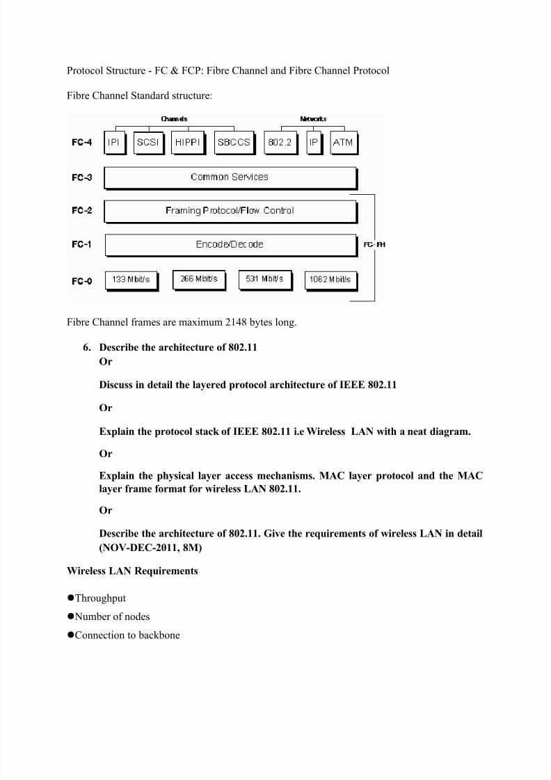
Fibre Channel consists of the following layers:
FC-0 -- The interface to the physical media
FC-1 -- The encoding and decoding of data and out-of-band physical link control information for
transmission over the physical media
FC-2 -- The transfer of frames, sequences and Exchanges comprising protocol information units.
FC-3 -- Common Services required for advanced features such as striping, hunt group and
multicast.
FC-4 -- Application interfaces that can execute over fibre channel such as the fibre channel
protocol for SCSI (FCP).
The fundamental entity in fibre channel is the fibre channel network. Unlike a layered network
architecture, a fibre channel network is largely specified by functional elements and theinterfaces between them. These consist, in part, of the following:
N_PORTs -- The end points for fibre channel traffic.
FC Devices -- The fibre channel devices to which the N_PORTs provide access.
Fabric Ports -- The interfaces within a fibre channel network that provide attachment for an
N_PORT.
The network infrastructure for carrying frame traffic between N_PORTs.
Within a switched or mixed fabric, a set of auxiliary servers, including a name server for device
discovery and network address resolution.
The principal fibre channel network topologies consist of the following:
Arbitrated Loop -- A series of N_PORTs connected together in daisy-chain fashion.
Switched Fabric -- A network consisting of switching elements.
Mixed Fabric -- A network consisting of switches and "fabric-attached" loops. A loop-attached
N_PORT (NL_PORT) is connected to the loop through an L_PORT and accesses the fabric byway of an FL_PORT.
8/13/2019 HSN 1st unit 16m q&a (1)
http://slidepdf.com/reader/full/hsn-1st-unit-16m-qa-1 20/32
Protocol Structure - FC & FCP: Fibre Channel and Fibre Channel Protocol
Fibre Channel Standard structure:
Fibre Channel frames are maximum 2148 bytes long.
6. Describe the architecture of 802.11
Or
Discuss in detail the layered protocol architecture of IEEE 802.11
Or
Explain the protocol stack of IEEE 802.11 i.e Wireless LAN with a neat diagram.
Or
Explain the physical layer access mechanisms. MAC layer protocol and the MAC
layer frame format for wireless LAN 802.11.
Or
Describe the architecture of 802.11. Give the requirements of wireless LAN in detail
(NOV-DEC-2011, 8M)
Wireless LAN Requirements
Throughput
Number of nodes
Connection to backbone

8/13/2019 HSN 1st unit 16m q&a (1)
http://slidepdf.com/reader/full/hsn-1st-unit-16m-qa-1 21/32

8/13/2019 HSN 1st unit 16m q&a (1)
http://slidepdf.com/reader/full/hsn-1st-unit-16m-qa-1 22/32
IEEE 802.11 PROTOCOL ARCHITECTURE
IEEE 802.11 is defined within the protocol architecture developed as an IEEE 802 standard,
consisting of three layers: logical link control (LLC), media access control (MAC), and physical.The LLC layer provides an interface to higher layers and performs basic link layer functions
such as error control and flow control. Every LAN consists of devices that must share its
transmission capacity.Thus,an individual LAN needs some way to control access to the

8/13/2019 HSN 1st unit 16m q&a (1)
http://slidepdf.com/reader/full/hsn-1st-unit-16m-qa-1 23/32
transmission medium so that devices will use that capacity in an orderly and efficient
manner.This responsibility falls to the MAC protocol, which ensures that all the devices on a
LAN cooperate.The MAC protocol requires that only one mobile device transmit at a time, and itspecifies that data be transmitted in blocks,or MAC frames. Each frame includes user data, a
destination and source address, errordetection code, and MAC control bits. Each mobile device
monitors the shared medium for frames with a destination address that matches its address, andcopies frames addressed to itself. For IEEE 802.11, the MAC layer has two sublayers. The lowerone is the distributed coordination function, which uses an Ethernet-style contention algorithm
that provides access to all traffic. Ordinary asynchronous traffic uses this coordination function.
The upper MAC sublayer is the point coordination function, a centralized MAC algorithm that provides contention-free service by polling mobile devices in turn. Higher-priority traffic —
traffic with greater timing requirements — uses this coordination function.The physical layer
defines the frequency band, data rate, and other details of the actual radio transmission.
PHYSICAL-LAYER STANDARDSWithin IEEE 802.11’s layered protocol architecture, the physical layer describes the frequency
band, data rate, and encoding technique provides some details about each physicallayer standard.The original standard, known simply as
IEEE 802.11, defined the MAC layer and three physical layers. The three physical media that the
original 802.11 standard
defined are the following:• Direct-sequence spread spectrum (DSSS).
The standard defines this medium as operating in the 2.4-GHz ISM band, at data rates of 1 Mbps
and 2 Mbps. In the US, the Federal Communications Commission (FCC) requires no licensing touse this band.The total number of available channels depends on the bandwidth that the various
national regulatory agencies allocate.
This ranges from 13 in most European countries to just one available channel in Japan.
• Frequency-hopping spread spectrum (FHSS).The standard also defines this medium operatingin the 2.4-GHz ISM band, at data rates of 1 Mbps and 2 Mbps. The number of channels available
ranges from 23 in Japan to 70 in the US.
• Infrared. At 1 Mbps and 2 Mbps, operating at a wavelength between 850 and 950 nm, thisoption never gained market support because it requires unobstructed lineof- sight and because
the available data rates are limited.
The first two schemes use spread-spectrum approaches.Spread spectrum essentially involvesusing a much wider bandwidth than is actually necessary to support a given data rate.Using a
wider bandwidth minimizes interference and drastically reduces the error rate. FHSS spreads the
spectrum by repeatedly jumping from one carrier frequency to another; thus, interference or
performance degradation at a given frequency only affects a small fraction of the transmission.DSSS effectively increases a signal’s data rate by mapping each data bit into a string of bits,
using one string for binary 1 and another for binary 0. The higher data rate uses a greater
bandwidth.The effect is to spread each data bit out over time, minimizing the effects of
interference and degradation. Most early 802.11 networks employed FHSS, which is somewhatless complex to implement than DSSS. Products using DSSS fol lowed; DSSS is more effective
in the 802.11 scheme in
terms of resistance to interference.However, all of the original DSSS 802.11 products were of
limited use because of their low data rates.

8/13/2019 HSN 1st unit 16m q&a (1)
http://slidepdf.com/reader/full/hsn-1st-unit-16m-qa-1 24/32
802.11a
The IEEE 802.11a specification uses the 5-GHz band. The working group established this
standard so US users could take advantage of a newly allocated unlicensed radio band, the
Unlicensed National Information Infrastructure (UNII) band. The FCC created UNII so
manufacturers could develop high-speed wireless networks.To find enough bandwidth to meetdemand, the FCC established the band at 5 GHz, making it incompatible with 2.4-GHz
equipment. Unlike the 2.4-GHz specifications, IEEE 802.11a uses OFDM rather than a spread-
spectrum scheme.OFDM,also called multicarrier modulation, uses multiple carrier signals at
different frequencies, sending some of the bits on each channel.This is similar to FDM
(frequency-division multiplexing), which uses each subchannel for a separate data source.
OFDM, however, dedicates all of the subchannels to a single data source.The possible data rates
per channel for IEEE 802.11a are 6, 9, 12, 18, 24, 36, 48, and 54 Mbps.
802.11b
IEEE 802.11b is an extension of the IEEE 802.11 DSSS scheme, providing data rates of 5.5 and
11 Mbps. Each channel requires the same 11-MHz bandwidth as an 802.11 DSSS channel.To
achieve a higher data rate in the same bandwidth, the standard employs a modulation scheme
called complementary code keying. IEEE 802.11b is currently the most commonly used 802.11
standard in commercial products.
802.11g
IEEE 802.11g extends 802.11b to data rates of 12 to 54 Mbps per channel. IEEE 802.11g is
compatible with 802.11b because they both operate in the 2.4-GHz range. The key difference
between 802.11b and 802.11g is that the latter uses OFDM and DSSS rather than DSSS only.
With this standard, 802.11b devices will work when connected to an 802.11g access point, and
802.11g devices will work when connected to an 802.11b access point, in both cases using the
lower 802.11b data rate.
Other IEEE 802.11 standards
The standards discussed so far provide specific physicallayer functionality, but several other
802.11 standards are in place or in development, as Table 2 shows. IEEE 802.11c covers bridge
operation. A bridge is a device that links to LANs with a similar or identical MAC protocol. It
performs functions similar to those of an Internet Protocol (IP)-level router, but at the MAClayer. Typically, a bridge is simpler and more efficient than an IP router. In 2003, the 802.11c
task group completed its work on this standard, which folded into the IEEE 802.1d standard for
LAN bridges. IEEE 802.11d is a regulatory domain update. It covers issues related to regulatory
differences in various countries. IEEE 802.11e revises the MAC layer to improve QoS and
address MAC enhancement. It accommodates time-scheduled and polled communication during
null periods when no other data is moving through the system. In addition, IEEE 802.11e

8/13/2019 HSN 1st unit 16m q&a (1)
http://slidepdf.com/reader/full/hsn-1st-unit-16m-qa-1 25/32
improves polling efficiency and channel robustness. These enhancements should provide the
quality necessary for services such as IP telephony and video streaming.A QoS station is any
base station implementing 802.11e. In a QoS station, a hybrid coordination function (HCF)
replaces modules for a distributed coordination function (DCF) and point coordination function
(PCF).The HCF consists of enhanced distributed-channel access (EDCA) and HCF-controlled
channel access (HCCA). EDCA extends the legacy DCF mechanism to include priorities. As
with the PCF, HCCA centrally manages medium access, but does so more efficiently and
flexibly.
IEEE 802.11f addresses interoperability among access points from multiple vendors. In addition
to providing communication among WLAN stations in its area, an access point can function as a
bridge that connects two 802.11 LANs across another type of network, such as an Ethernet LAN
or a wide area network. So IEEE 802.11f facilitates the roaming of a device from one access
point to another while ensuring transmission continuity.
IEEE 802.11h covers spectrum and power management. The objective is to make 802.11a products compliant with European regulatory requirements. The European Union military uses
part of the 5-GHz band for satellite communications.
The standard includes a dynamic channel selection mechanism to prevent selection of the
frequency band’s restricted portion. The standard’s transmit-power-control features adjust power
to EU requirements. IEEE 802.11i defines security and authentication mechanisms at the MAC
layer. This standard addresses security deficiencies in the Wired Equivalent Privacy (WEP)
algorithm originally designed for the MAC layer of 802.11. The 802.11i scheme’s stronger
encryption and other enhancements improve security.
IEEE 802.11j addresses 4.9- and 5-GHz operation in Japan.
IEEE 802.11k defines enhancements that provide mechanisms available to protocol layers above
the physical layer for radio resource measurement. The standard specifies what information
should be available to facilitate the management and maintenance of wireless and mobile LANs,
including the following:
• To improve roaming decisions, an access point can provide a site report to a mobile device
when the access point determines that the mobile device is moving away from it. The site report
lists access points — from best to worst service — that a mobile device can use in changing over to
another access point.
• An access point can collect channel information from each mobile device on the WLAN. Each
mobile device provides

8/13/2019 HSN 1st unit 16m q&a (1)
http://slidepdf.com/reader/full/hsn-1st-unit-16m-qa-1 26/32
a noise histogram that displays all non-802.11 energy on that channel as perceived by the mobile
device.The access point also collects statistics on how long a channel is in active use during a
given time.This data enable the access point to regulate access to a given channel.
• Access points can query mobile devices to collect statistics, such as retries, packets transmitted,
and packets received. This gives the access point a more complete view of network performance.
• 802.11k extends the transmit-power-control procedures (defined in 802.11h) to other regulatory
domains and frequency bands, to reduce interference and power consumption, and to provide
range control.
IEEE 802.11m is an ongoing task group activity to correct editorial and technical issues in the
802.11 standard. The other task groups generate documents, and the 802.11m task group reviews
those documents to locate and correct inconsistencies and errors in the 802.11 standard and its
approved amendments. The IEEE 802.11n task group is studying various enhancements to the
physical and MAC layers to improve throughput. These enhancements include such items asmultiple antennas, smart antennas, changes to signal encoding schemes, and changes to MAC
protocols. The task group’s curr ent objective is a data rate of at least 100 Mbps, as measured at
the interface between the 802.11 MAC layer and higher layers.
7. What are the services provided by ATM adaptation layer? Explain the operation of
various AAL protocols
Or
Explain the structure of the ATM adaptation layer and compare AAL protocol in
detail
Or
Discuss and compare the CPCS-PDU & SAR-PDU of AAL ¾ & AAL 5
The use of Asynchronous Transfer Mode (ATM) technology and services creates the need for anadaptation layer in order to support information transfer protocols, which are not based on ATM.This adaptation layer defines how to segment and reassemble higher-layer packets into ATM
cells, and how to handle various transmission aspects in the ATM layer.
Examples of services that need adaptations are Gigabit Ethernet, IP, Frame Relay, SONET/SDH,
UMTS/Wireless, etc.
The main services provided by AAL (ATM Adaptation Layer) are:
Segmentation and reassembly
Handling of transmission errors
Handling of lost and misinserted cell conditions
Timing and flow control

8/13/2019 HSN 1st unit 16m q&a (1)
http://slidepdf.com/reader/full/hsn-1st-unit-16m-qa-1 27/32
The following ATM Adaptation Layer protocols (AALs) have been defined by the ITU-T. It is
meant that these AALs will meet a variety of needs. The classification is based on whether a
timing relationship must be maintained between source and destination, whether the applicationrequires a constant bit rate, and whether the transfer is connection oriented or connectionless.
AAL Type 1 supports constant bit rate (CBR), synchronous, connection oriented traffic.Examples include T1 (DS1), E1, and x64 kbit/s emulation.
AAL Type 2 supports time-dependent Variable Bit Rate (VBR-RT) of connection-oriented,
synchronous traffic. Examples include Voice over ATM. AAL2 is also widely used in wirelessapplications due to the capability of multiplexing voice packets from different users on a singleATM connection.
AAL Type 3/4 supports VBR, data traffic, connection-oriented, asynchronous traffic (e.g. X.25data) or connectionless packet data (e.g. SMDS traffic) with an additional 4-byte header in the
information payload of the cell. Examples include Frame Relay and X.25.
AAL Type 5 is similar to AAL 3/4 with a simplified information header scheme. This AAL
assumes that the data is sequential from the end user and uses the Payload Type Indicator (PTI) bit to indicate the last cell in a transmission. Examples of services that use AAL 5 are classic IP
over ATM, Ethernet Over ATM, SMDS, and LAN Emulation (LANE). AAL 5 is a widely usedATM adaptation layer protocol. This protocol was intended to provide a streamlined transportfacility for higher-layer protocols that are connection oriented.
AAL 5 was introduced to:
reduce protocol processing overhead.
reduce transmission overhead.
ensure adaptability to existing transport protocols.
AAL1 PDU
The structure of the AAL1 PDU is given in the following illustration:
SN SNP
CSI SC CRC EPC SAR PDU Payload
1 bit 3 bits 3 bits 1 bit 47 bytes
AAL1 PDU
SN - Sequence number. Numbers the stream of SAR PDUs of a CPCS PDU (modulo 16). The
sequence number is comprised of the CSI and the SN.
CSI - Convergence sublayer indicator. Used for residual time stamp for clocking.
SC - Sequence count. The sequence number for the entire CS PDU, which is generated by theConvergence Sublayer.
SNP - Sequence number protection. Comprised of the CRC and the EPC.

8/13/2019 HSN 1st unit 16m q&a (1)
http://slidepdf.com/reader/full/hsn-1st-unit-16m-qa-1 28/32
CRC - Cyclic redundancy check calculated over the SAR header.
EPC - Even parity check calculated over the CRC.
SAR PDU payload - 47-byte user information field.
AAL2
AAL2 provides bandwidth-efficient transmission of low-rate, short and variable packets in delay sensitive
applications. It supports VBR and CBR. AAL2 also provides for variable payload within cells and across
cells. AAL type 2 is subdivided into the Common Part Sublayer (CPS ) and the Service Specific
Convergence Sublayer (SSCS ).
AAL2 CPS Packet
The CPS packet consists of a 3 octet header followed by a payload. The structure of the AAL2 CPS
packet is shown in the following illustration.
CID LI UUI HEC Information payload
8 bits 6 bits 5 bits 5 bits 1-45/64 bytes
AAL2 CPS packet
CID-Channelidentification.
LI - Length indicator. This is the length of the packet payload associated with each individual user. Value
is one less than the packet payload and has a default value of 45 bytes (may be set to 64 bytes).
UUI - User-to-user indication. Provides a link between the CPS and an appropriate SSCS that satisfies the
higher layer application
HEC - Header error control.
AAL2
The structure of the AAL2 SAR PDU is given in the following illustration.
Start field CPS-PDU payload
OSF SN P AAL2 PDU payload PAD
6 bits 1 bit 1 bit 0-47
bytes

8/13/2019 HSN 1st unit 16m q&a (1)
http://slidepdf.com/reader/full/hsn-1st-unit-16m-qa-1 29/32
AAL2 CPS PDU
OSF - Offset field. Identifies the location of the start of the next CPS packet within the CPS-PDU.
SN - Sequence number. Protects data integrity.
P - Parity. Protects the start field from errors.
SAR PDU payload - Information field of the SAR PDU.
PAD - Padding.
AAL2 SSCS Packet
The SSCS conveys narrowband calls consisting of voice, voiceband data or circuit mode data. SSCS
packets are transported as CPS packets over AAL2 connections. The CPS packet contains a SSCS
payload. There are 3 SSCS packet types.
Type 1 Unprotected; this is used by default.
Type 2 Partially protected.
Type 3 Fully protected: the entire payload is protected by a 10-bit CRC which is computed as for OAM
cells. The remaining 2 bits of the 2-octet trailer consist of the message type field.
AAL2 SSCS Type 3 Packets:
The type 3 packets are used for the following:
Dialled digits
Channel associated signalling bits
Facsimile demodulated control data
Alarms User state control operations.
The following illustration gives the general sturcture of AAL2 SSCS Type 3 PDUs. The format varies and
each message has its own format according to the actual message type.
Redundancy Time
stamp
Message
dependant
information
Message
type
CRC-10
2 14 16 6 10 bits

8/13/2019 HSN 1st unit 16m q&a (1)
http://slidepdf.com/reader/full/hsn-1st-unit-16m-qa-1 30/32
AAL2 SSCS Type 3 PDU
Redundancy - Packets are sent 3 times to ensure error correction. The value in this field signifies thetransmission number.
Time stamp - Counters packet delay variation and allows a receiver to accurately reproduce the relative
timing of successive events separated by a short interval.
Message dependant information - Packet content that varies, depending on the message type.
Message type - The message type code.
CRC-10 - The 10-bit CRC.
AAL3/4
AAL3/4 consists of message and streaming modes. It provides for point-to-point and point-to-multipoint
(ATM layer) connections. The Convergence Sublayer (CS) of the ATM Adaptation Layer (AAL) is
divided into two parts: service specific (SSCS ) and common part (CPCS ). This is illustrated in the
following diagram:
AAL3/4 packets are used to carry computer data, mainly SMDS traffic.
AAL3/4 CPCS PDU
The functions of the AAL3/4 CPCS include connectionless network layer (Class D), meaning no need for
an SSCS; and frame relaying telecommunication service in Class C. The CPCS PDU is composed of the
following fields:
Header Info
Trailer
CPI Btag Basize CPCS
SDU
Pad 0 Etag Length
1 1 2 0-65535 0-3 1 1 2 bytes
AAL3/4 CPCS PDU
CPI - Message type. Set to zero when the BAsize and Length fields are encoded in bytes.

8/13/2019 HSN 1st unit 16m q&a (1)
http://slidepdf.com/reader/full/hsn-1st-unit-16m-qa-1 31/32
Btag - Beginning tag. This is an identifier for the packet. It is repeated as the Etag.
BAsize - Buffer allocation size. Size (in bytes) that the receiver has to allocate to capture all the data.
CPCS SDU - Variable information field up to 65535 bytes.
PAD - Padding field which is used to achieve 32-bit alignment of the length of the packet.
0 - All-zero.
Etag - End tag. Must be the same as Btag.
Length - Must be the same as BASize.
AAL3/4 SAR PDU
The structure of the AAL3/4 SAR PDU is illustrated below:
ST SN MID Information LI CRC
2 4 10 352 6 10 bits
2-byte header 44 bytes 2-byte trailer
48 bytes
AAL3/4 SAR PDU
ST - Segment type. Values may be as follows:
SN - Sequence number. Numbers the stream of SAR PDUs of a CPCS PDU (modulo 16).
MID - Multiplexing identification. This is used for multiplexing several AAL3/4 connections over one
ATM link.
Information- This field has a fixed length of 44 bytes and contains parts of CPCS PDU.
LI - Length indication. Contains the length of the SAR SDU in bytes, as follows:
CRC - Cyclic redundancy check.
Functions of AAL3/4 SAR include identification of SAR SDUs; error indication and handling; SAR SDU
sequence continuity; multiplexing and demultiplexing.

8/13/2019 HSN 1st unit 16m q&a (1)
http://slidepdf.com/reader/full/hsn-1st-unit-16m-qa-1 32/32
AAL5 The type 5 adaptation layer is a simplified version of AAL3/4. It also consists of message and
streaming modes, with the CS divided into the service specific and common part. AAL5 provides point-
to-point and point-to-multipoint (ATM layer) connections.
AAL5 is used to carry computer data such as TCP/IP. It is the most popular AAL and is sometimes
referred to as SEAL (simple and easy adaptation layer).
AAL5 CPCS PDU
The AAL5 CPCS PDU is composed of the following fields:
Info
Trailer
CPCS payload Pad UU CPI Length CRC
0-65535 0-47 1 1 2 4 bytes
AAL5 CPCS PDU
CPCS - The actual information that is sent by the user. Note that the information comes before any length
indication (as opposed to AAL3/4 where the amount of memory required is known in advance).
Pad - Padding bytes to make the entire packet (including control and CRC) fit into a 48-byte boundary.
UU - CPCS user-to-user indication to transfer one byte of user information.
CPI - Common part indicator is a filling byte (of value 0). This field is to be used in the future for layermanagement message indication.
Length - Length of the user information without the Pad.
CRC - CRC-32. Used to allow identification of corrupted transmission.
AAL5 SAR PDU The structure of the AAL5 CS PDU is as follows:
Information PAD UU CPI Length CRC-32
1-48 0-47 1 1 2 4 bytes
8-byte trailer
AAL5 SAR PDU