hs/s4.2.1 gb brightness sensor - abb ltd · the switching channels menu item displays the status of...
TRANSCRIPT
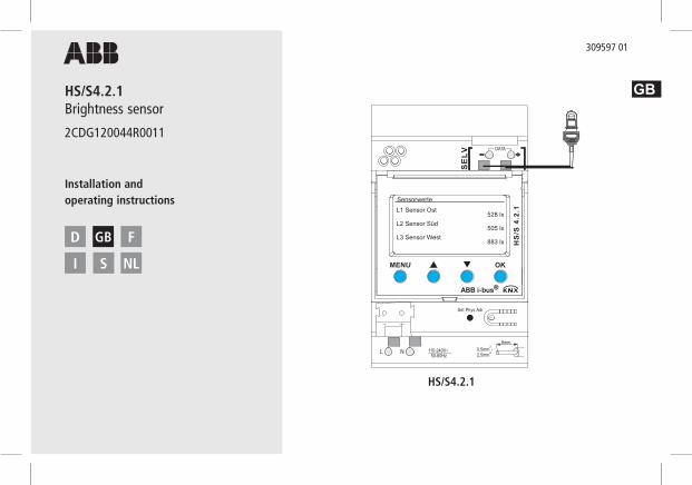
HS/S4.2.1 Brightness sensor
2CDG120044R0011
GB
Installation and operating instructions
D GB F
I S NL
309597 01
HS/S4.2.1
C2C3C4
C1
E
MENU OK
TR 6
44 to
p2 R
C
DATA
0 6 12 18 24
C1
C2
C3
C4
Ext1
L N
1C1
2 3µ
4C2
5 6µ
Ext2 Ext3 Ext4
10C4
11 12µ
7C3
8 9µ
22,5mm2 0,5mm -
110-240V~50-60Hz
R8a - 30T
C2/C416(10)A 250V~C1/C310(10)A 250V~
8mm L N
- +
NLL
max
. 100
mm
ax. 1
00 m
max
. 100
mm
ax. 1
00 m
DA
Set Phys Adr
HS
/S 4
.2.1
SE
LV
TA
MENU OK
L N 110-240V~50-60Hz
22,5mm2 0,5mm -
8mm
C2C3C4
C1C6C7C8
C5
Sensorwerte
L1 Sensor Ost 528 lxL2 Sensor Süd 505 lxL3 Sensor West 883 lx

ContentsBasic safety instructions 3Display and keys 4Connection/installation 5Bus connection, programming physical address 6 Start-up 7 Home page – Sensor values 7 Enter PIN Menu – Settings.. 8 Language.. 9 Display.. 9 System.. 10 Sensors.. 11 Deactivate active sensor 11 Allocate new serial number to active sensor 12Menu – Switching channels.. 13 Select light threshold (brightness) 14 Select delay 15
Technical date 16Service address/Hotline 162
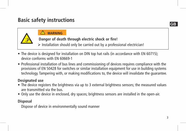
Basic safety instructions
• The device is designed for installation on DIN top hat rails (in accordance with EN 60715); device conforms with EN 60669-1• Professional installation of bus lines and commissioning of devices requires compliance with the provisions of EN 50428 for switches or similar installation equipment for use in building systems technology. Tampering with, or making modifications to, the device will invalidate the guarantee.
Designated use • The device registers the brightness via up to 3 external brightness sensors; the measured values are transmitted via the bus.• Only use the device in enclosed, dry spaces; brightness sensors are installed in the open-air.
Disposal Dispose of device in environmentally sound manner
Danger of death through electric shock or fire! Installation should only be carried out by a professional electrician!
WARNING
3
GB

4
Screen and keys
C2C3C4
C1
E
MENU OK
TR 6
44 to
p2 R
C
DATA
0 6 12 18 24
C1
C2
C3
C4
Ext1
L N
1C1
2 3µ
4C2
5 6µ
Ext2 Ext3 Ext4
10C4
11 12µ
7C3
8 9µ
22,5mm2 0,5mm -
110-240V~50-60Hz
R8a - 30T
C2/C416(10)A 250V~C1/C310(10)A 250V~
8mm L N
- +
NLL
max
. 100
mm
ax. 1
00 m
max
. 100
mm
ax. 1
00 m
DA
Set Phys Adr
HS
/S 4
.2.1
SE
LV
TA
MENU OK
L N 110-240V~50-60Hz
22,5mm2 0,5mm -
8mm
C2C3C4
C1C6C7C8
C5
Sensorwerte
L1 Sensor Ost 528 lxL2 Sensor Süd 505 lxL3 Sensor West 883 lx
Screen display, e. g. sensor values
? MENU
– Activate screen– Open menu– Cancel menu– ESC (1 step back)
? OK
– Store selection– Confirm selection
p q
Options are displayed
Connection/installation
L N
NL
Data
Lux
Lux
Lux
KNX

5
Connection/installation
Connect cable Strip cable by 8 mm (max. 9 mm). Insert cable at 45° in the open terminal (2 cables per terminal position possible). With flexible wires only: To open the spring terminal, press screwdriver downwards.
Danger of death through electric shock! Must only be installed by professional electrician! Disconnect power source! Cover or shield any adjacent live components. Ensure device cannot be switched again! Check power supply is disconnected! Earth and bypass! Observe SELV on data bus.
WARNING
Spring screwless terminalNC contact
Test connection
Spring terminal
45° cable
GB
6
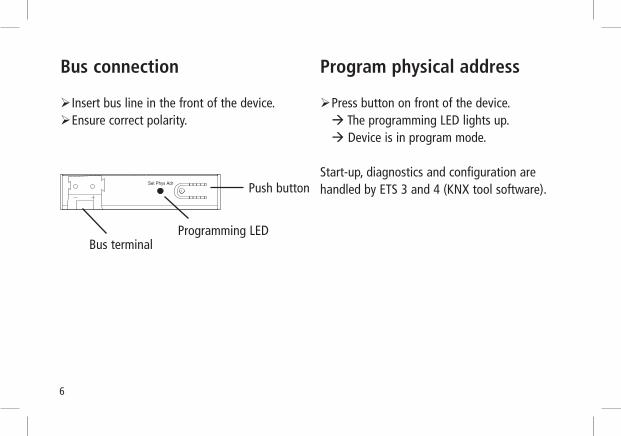
Bus connection
Insert bus line in the front of the device. Ensure correct polarity.
Program physical address
Press button on front of the device. à The programming LED lights up. à Device is in program mode.
Start-up, diagnostics and configuration are handled by ETS 3 and 4 (KNX tool software).Push button
Programming LED
C2C3C4
C1
E
MENU OK
TR 6
44 to
p2 R
C
DATA
0 6 12 18 24
C1
C2
C3
C4
Ext1
L N
1C1
2 3µ
4C2
5 6µ
Ext2 Ext3 Ext4
10C4
11 12µ
7C3
8 9µ
22,5mm2 0,5mm -
110-240V~50-60Hz
R8a - 30T
C2/C416(10)A 250V~C1/C310(10)A 250V~
8mm L N
- +
NLL
max
. 100
mm
ax. 1
00 m
max
. 100
mm
ax. 1
00 m
DA
Set Phys Adr
TR 6
48 t
op 2
RC
KN
X
SE
LV
TA
MENU OK
L N
C2C3C4
C1C6C7C8
C5
110-240V~50-60Hz
R8a - 5T22,5mm2 0,5mm -
8mm
ESC
ESC OK
Bus terminal

Start-upThe pages displayed depends on the programming by the ETS. Please refer to the Product Handbook for detailed functional descriptions (at www.abb.com/knx).
Home page – Sensor valuesIf an external sensor is connected, the sensor value (lux value)
appears on screen. The sensor LED flashes.
Enter PINIf Access via PIN is set on the ETS, the pin code (1000–9999)
has to be entered before use.
Enter the numbers with q or p and confirm with OK.
MENU OK
Sensor values
No sensors allocated
MENU OK
Sensor valuesL1 sensor 1 622 lxL2 sensor 2 530 lx
7
GB

8
Menu – Settings..
The Settings menu item can be used for setting the language,
screen lighting or information on the device and sensors.
Press MENU button. This brings up Settings.. . Confirm settings.. by pressing OK. Use q or p to select language, display etc. Press OK to confirm or use q or p to select Back.
MENU OK
MENU OK
Menu Settings .. K1 :Switching channel 1.. K2 :Switching channel 2.. K3 :Switching channel 3.. K4 :Switching channel 4..Back
Settings Language .. Display .. System .. Sensors ..Back

9
MENU OK
MENU OK
Settings– Set language
Use q or p to select language.Press OK to confirm.Use q or p to select desired language.
Settings– Set display
Use q or p to select display.Press OK to confirm.
Language Deutsch English Francais Espanol Italiano Nederlands
Display
Light keypress Back
GB

10
MENU OK
Settings – System..
Use q or p to select system.
Press OK to confirm.
The display shows
Prog. mode (Programming mode)
PA (Physical address)
SW (Software version)
SN (Serial number)
FD (Finishing date)
HW (Hardware)
System Prog. mode Off PA: 15.15.255 SW: VI.0 SN: 0048112233445566 FD: 11.11.2011 HW: V0

11
Settings – Sensors..Use q or p to select sensors. Confirm by pressing OK.
The Sensors menu item can be used to display the lux values
for up to 3 connected sensors. The designation of the sensors
can be changed using the ETS:
– active (serial number is displayed)
– inactive (sensor is not required)
– Error (sensor does send)
Deactivate active sensorUse q or p to select the desired sensor. Confirm L1 sensor 1 (active) by pressing OK. This brings up serial numbers, lux value and Deactivate.Use q or p to select Deactivate. Confirm by pressing OK.
MENU OK
MENU OK
Process sensors L1 sensor 1 SN: 123456789 L2 sensor 2 inactive L3 sensor 3 ErrorBack
L1 sensor 1 SN: 123456789 500 lxDeactivate
Back
GB

12
If you want continue searching rather than accepting the sensor..Select Next serial number.Press OK to confirm.
MENU OK
L1 sensor 1 SN: 123456789 500 lxNext serial numberAllocateBack
Allocate new serial number to inactive sensorUse q or p to select Next serial number.Press OK to confirm.
The inactive sensor displays a new SN number. Use q or p to select Allocate. Press OK to confirm and, if reqd., select Back to leave menu.
MENU OK
L1 sensor 1inactive Next serial numberAllocateBack

13
MENU OK
K1 :Switching channel 1..Status: ONLight thresholds..Next channelBack..
MENU OK
Menu Settings .. K1 :Switching channel 1.. K2 :Switching channel 2.. K3 :Switching channel 3.. K4 :Switching channel 4..Back
Menu – Switching channels..
The Switching channels menu item displays the status of the
channel (ON, OFF, disabled/invalid):
Press MENU button. This brings up Settings.. and the Switching channels.. etc. Use q or p K1: to select Switching channel 1.Press OK to confirm. It brings up Status (ON, OFF), Light thresholds.. and Next channel...
GB

14
Select light thresholds (brightness)
The Light thresholds menu item can be used to set of the
brightness of the relevant channel:
Use q or p to select Light thresholds. Press OK to confirm. Use q or p to select lux value. Press OK to confirm. Use q or p to change lux value. Press OK to confirm desired lux value.
MENU OK
K1 :Brightness Completed > 20 lux Uncompleted < 16 luxDelay..Back..
MENU OK
K1 :Switching channel 1..Status: OFFLight thresholds..Next channelBack..

15
Select delay
The Delay menu item can be used to set the delay time:
Use q or p to select Delay. Press OK to confirm. Use q or p to select Exceed or Underrun. Press OK to confirm selection. Use q or p to change the delay values. Press OK to select desired delay value.
MENU OK
K1 :Delay Exceed 15 s Underrun 90 s Back..
GB

16
Technical data• Operating voltage: 110 –240 V~, +10 %/-15 %• Frequency: 50–60 Hz• Power consumption: typically 1 W• Standby min.: 0.8 W• Data output: Safety Extra Low Voltage (SELV)• Permissible ambient temperature: –5 °C ... +45 °C –40 °C ... +70 °C (sensor)• On/Off switching delay: 0–20 min• Brightness measuring range: 1–100000• Protection class: II subject to correct installation• Protection rating: IP 20 in accordance with EN 60529• Pollution level: 2
• Max. cable cross section: 2.5 mm2
• Operating voltage KNX: bus voltage ≤10 mA• Cable length: 100 m (YCYM 2 x 2 x 0.8 mm 2 pairs for DATA bus) 50 m (YCYM 2 x 2 x 0.8 mm
1 pair each for KNX and DATA bus) • Max. number of connectable brightness sensors for HS/S4.2.1 at DATA bus: 3
Service address
ABB STOTZ-KONTAKT GmbHEppelheimer Straße 8269123 HeidelbergGermanyTel. +49 6221 701-434Fax +49 6221 701-724www.abb.com/knx