ht-3000p-1a-ac rev 1 - compwest.com rev 1.0.pdfthe ht-3000p-1a-ac leakage test uses a separate...
TRANSCRIPT
HT-3000P-1A-AC
Dielectric Withstand Tester
0-3000 Volts AC Output
Instruction Manual


i
Dear Customer: Congratulations! Compliance West USA is proud to present you with your Dielectric Withstand Tester. Your instrument features a groundbreaking micro-controlled circuit design and ergonomic front panel, and represents the latest in high voltage production line testing. To fully appreciate all the features of your new meter, we suggest that you take a few moments to review this manual. If the need arises, please don't hesitate to contact us. Thank you for your trust and confidence.
Rev. 1.0, February, 2012

ii
iii
Table of Contents
Safety Precautions ........................................................................................................................2
Test Personnel ................................................................................................................2 Testing Area ...................................................................................................................2
Safety Techniques ........................................................................................................................3 Using the HT-3000P-1A-AC Dielectric Withstand Tester ...........................................................3
Leakage Test ..................................................................................................................3 Sporadic Leakage Current Failures ..................................................................4 Chronic Leakage Current Failures ...................................................................4 High Voltage Discharge ...................................................................................4
Introduction and Specifications ..................................................................................................................5 Specifications ...............................................................................................................................6
Operation ....................................................................................................................................................7 Setting up your Tester ..................................................................................................................7 AC Line Voltage Requirements....................................................................................................7 Fuse Replacement.........................................................................................................................7 Front Panel Features .....................................................................................................................7 Initial Checkout Procedure ...........................................................................................................10 Performance Test .........................................................................................................................10 Setting up the HT-3000P-1A-AC .................................................................................................10
Factory Settings..............................................................................................................11 Display of Leakage Limit and Duration settings ............................................................11 Adjustment of the Leakage Current Level .....................................................................11 Adjustment of the High Voltage Level ..........................................................................11 Adjustment of the High Voltage Test Time ...................................................................12
Operating Techniques ..................................................................................................................12 Daily Operation Test ......................................................................................................12 Test results .....................................................................................................................12
Red LED/Buzzer ..............................................................................................12 Technical Assistance ..................................................................................................................................13 Maintenance and Calibration ......................................................................................................................14
Introduction ..................................................................................................................................14 Service Information ......................................................................................................................14 General Maintenance ....................................................................................................................14
Cleaning .........................................................................................................................14 Calibration Procedure ...................................................................................................................15
Calibration and Software Version Information ..............................................................16 Voltage Calibration Adjustment .....................................................................................16 Current Calibration Adjustment .....................................................................................17

1
2
Section 1
Safety Precautions The dielectric withstand test generates voltages of up to 3000 volts ac at potentially lethal current levels. Currents of as little as 5 mA at 120 volts can cause death, and the HT-3000P-1A-AC is capable of generating 1 A at up to 3000 volts. The HT-3000P-1A-AC has been designed to minimize exposure to high voltages. However, the potential for serious injury or death exists and personnel should be aware when they conduct this test.
Test Personnel Personnel require special training to conduct the dielectric withstand test. They should understand electrical fundamentals clearly, and be aware that high voltage is adept and creative at completing a path to ground. Instructions should include a warning against any metal jewelry. Operators should not allow others in the testing area, especially when tests are being conducted. Organization is to be stressed. The operator should keep the area free of unused leads and equipment.
Testing Area
The area used for conducting the dielectric withstand test should be as remote as possible from normal production line activities. Only personnel actually conducting the test should be allowed in the area, and it should be taped or roped off to preclude casual entry by other employees. In addition, the area should be marked "WARNING - HIGH VOLTAGE TESTING" or the equivalent to warn others of the nature of the testing taking place. The bench being used should be non-conductive, and any exposed metal parts should be tied together and grounded. If a conductive surface must be used, it should be grounded. Because of sparking during a dielectric test failure, it is not safe to conduct dielectric withstand tests in combustible atmospheres. It is imperative that a good ground be provided to the HT-3000P-1A-AC. Before connecting the HT-3000P-1A-AC, ensure that a low-resistance ground is provided by the building wiring. If the HT-3000P-1A-AC is used on a high-resistance grounding circuit, dangerous high voltages may be present to the operator. In addition, the power to the Testing Area should be provided with an easily reached shutoff switch which can be actuated by personnel outside the Area if needed.
3
Safety Techniques The high voltage circuit of the HT-3000P-1A-AC can be shut off at any time by pressing
the RESET button. The HT-3000P-1A-AC has been provided with a Reset switch to provide an unarmed "Standby" setting when it is energized, but idle. When the red RESET button is lit. The tester will not provide high voltage until the RESET button and the TEST button have been pressed in order. To prevent inadvertent operation, the operator should be instructed not to press the RESET button until the test is ready. The HT-3000P-1A-AC has been designed for one-touch operation with the right hand. If possible, it should be set up to the left and in front of the equipment under test. The equipment under test should be connected to the HT-3000P-1A-AC and then left alone by the operator. After the operator is clear of the Tester and the equipment under test, he should press the RESET Button, then the TEST Button, with his right hand. This will allow the greatest separation between the operator and the test being conducted. The HT-3000P-1A-AC is designed to bleed the high voltage away after the test has concluded. In order to ensure that any voltage present in the equipment being tested has been completely bled away, the operator should not unplug the equipment under test from the HT-3000P-1A-AC until the front panel meter reads zero volts.
Using the HT-3000P-1A-AC Dielectric Withstand Tester The dielectric withstand test involves high voltage and caution should be exercised when using the tester. The tester's return lead is connected to ground potential and when properly connected to the equipment being tested, it will guard against the operator contacting high voltage. Always make sure the return lead is firmly connected to exposed dead metal.
Leakage Test The HT-3000P-1A-AC leakage test uses a separate low-frequency circuit to check for excessive leakage between primary power components and ground. There is not a specific leakage current level pass/fail requirement at this time for most equipment, however, higher than normal leakage current on a particular part may indicate an assembly or component problem in the primary circuit. The leakage current is also monitored by the HT-3000P-1A-AC to ensure that excessive leakage does not keep the tester from developing full voltage required for the high voltage test. The HT-3000P-1A-AC will provide full voltage at any leakage current level up to 1000 mA. The leakage current trip level is adjustable on the front panel. Excessive leakage current is not grounds for failure of the dielectric withstand test. Leakage current is a normal result of capacitance in the primary circuit between neutral or line conductors and ground. (In dielectric tests of some larger electric motors, leakage currents of as high as 95 mA are considered acceptable by safety agencies.) However, leakage currents higher than normally anticipated for a particular model should not be ignored. This indicates problems of low resistance up to a short circuit between line/neutral and ground, and failures should be investigated. Failure modes are discussed below. If the green Full Voltage LED lights and the test continues, the leakage current was below the amount set by the leakage adjust knob.

4
Sporadic Leakage Current Failures
If the red Excess Leakage LED lights, the buzzer sounds, and the test is terminated, the leakage current delivered to the equipment being tested was over the amount set by the leakage adjust knob. If other equipment of the same type routinely passes this test, there may be a problem, the unit should be checked and reworked if necessary.
Chronic Leakage Current Failures AC Dielectric Withstand testing charges all primary circuit capacitors connected line to ground or neutral to ground. The current flowing through these capacitors is defined as leakage current. If almost all examples of a model of equipment are not passing the leakage current test, we recommend that the leakage current limit be increased by resetting the leakage current level on the rear panel to a higher level. If the leakage current adjustment of the HT-3000P-1A-AC is set to 1 A and almost all the samples of the model being tested are still failing, the primary circuit capacitance of the equipment may be too high to allow the AC dielectric withstand test to be used. This is due to the AC voltage charging all capacitors connected between primary voltage and ground. If the overall value of these capacitors produce a leakage current of more than 1 A to flow at the desired test voltage, the HT-3000P-1A-AC cannot generate full voltage, and cannot successfully conduct the dielectric withstand test. However, a DC dielectric withstand test is acceptable for most categories of equipment and will not cause leakage through the primary circuit capacitors. A DC voltage dielectric withstand tester, may allow successful test of models chronically failing the HT-3000P-1A-AC leakage current test.
High Voltage Discharge
The HT-3000P-1A-AC is designed to discharge the high voltage after completion of the
dielectric withstand test. The equipment being tested should remain connected to the HT-3000P-1A-AC until the voltage has discharged to a safe level to protect the operator and also to ensure that there is no energy stored in the tested equipment.
5
Section 2
Introduction and Specifications
This manual contains complete operating, maintenance and calibration instructions for
the Compliance West USA Model HT-3000P-1A-AC Dielectric Withstand Tester. The HT-3000P-1A-AC is a bench-type Dielectric Withstand Tester with AC Output.
The HT-3000P-1A-AC features automatic one button operation, with numerous safety
features designed to protect the operator: - The Return Lead is directly connected to ground potential for operator safety. - In case of trouble, the test can be immediately terminated at any time by pressing the
RESET button. - Before the test can commence, the unit must be armed by pressing the RESET Button. The
test will not begin until the TEST Button is pushed. - If a failure is encountered, the high voltage is immediately shut down, a buzzer sounds, and
any voltage stored in the equipment being tested is bled off by a resistor bank in the HT-3000P-1A-AC. The voltage discharge progress is shown by the front panel meter.
- Failure modes are shown by the front panel LED's for quick troubleshooting. Convenience and testing features include: - Test results are determined quickly, without operator intervention. - The HT-3000P-1A-AC allows custom setups for test time and leakage limit. - Voltage is discharged by a resistor bank within the HT-3000P-1A-AC upon test
completion. Discharge progress is shown on the front panel meter. Your Tester is warranted for a period of one year upon shipment of the instrument to the original purchaser.

6
Specifications
Specifications for the HT-3000P-1A-AC are listed in Table 1.
ELECTRICAL Output 0-3000 Volts AC Leakage Current 30-1000 mA Pass/Fail Criteria: Leakage Current: User adjustable 30-1000 mA Test Time: User adjustable 1-60 sec. Pass/Fail Repeatability ± 3% Meter accuracy + 2% from 500-3000 volts AC Duty cycle 100 % Discharge Time Voltage dependent; discharge progress displayed on front panel meter Test adjustments Tamperproof operation available ENVIRONMENTAL Operating Temperature 15-40°C Relative Humidity Range 0-90% non-condensing GENERAL Input power requirements 240V, 60 Hz, 15A single phase Weight 180 lbs approximated SAFETY AGENCY TOPICS Transformer Output >500VA Visual Indication of Voltage Output Provided by
front panel meter, directly connected to high voltage output
Failure Indication Audible, provided by internal buzzer Visual, provided by red LED's on front panel Test automatically terminated on failure Leakage Test provided; 50 mA factory set pass/fail
point, user adjustable.
Table 1. HT-3000P-1A-AC Specifications
7
Section 3
Operation
This section describes how to set up and make measurements with your tester. We recommend that you read the entire section carefully so that you can use all of the features of your tester.
Setting up your Tester
Your tester is shipped in a special protective container that should prevent damage to the instrument during shipping. Check the shipping order against the contents of the container and report any damage or short shipment to Compliance West USA. The container should include the following: - The HT-3000P-1A-AC Dielectric Withstand Tester - Test leads (with Alligator Clips ends, one Green and one Red) - Calibration Certificate - This Instruction Manual - Keys to open the rear door
If reshipment of the instrument is necessary, please use the original shipping container. If the original shipping container is not available, be sure that adequate protection is provided to prevent damage during shipment. We recommend that the instrument be surrounded by at least three inches of shock-absorbing material on all sides of the container.
AC Line Voltage Requirements
AC line voltage requirements for your Tester are noted on the rear panel of the instrument. Do not connect the instrument to a different voltage source.
Fuse Replacement
There are two user-replaceable fuses (F1) located on the front panel of the instrument and the other one is inside the equipment. The F1 fuse rating is noted on the rear panel. Do not attempt to replace it with a fuse of any other rating. Use the following procedure to replace the fuse F1: 1. Turn the power switch to the O or Off position. 2. Unplug the instrument from the source of supply. 3. Twist the cover of the fuse holder and remove it. 4. Replace the fuse with a new one of the correct rating. 5. Replace the fuse holder cover.
Front Panel Features
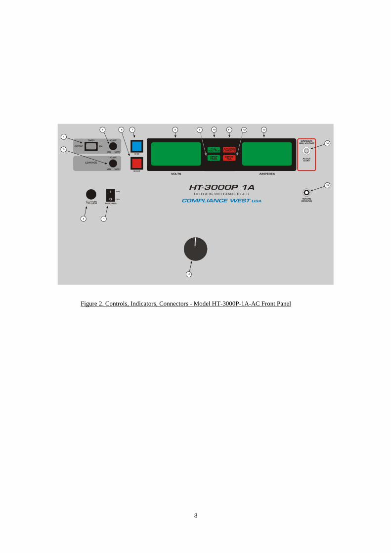
Before using your tester, take a few minutes to become familiar with the use of its controls, indicators, and connectors. The front panel features of the HT-3000P-1A-AC are shown in Figure 2 and described in Table 2.
8
Figure 2. Controls, Indicators, Connectors - Model HT-3000P-1A-AC Front Panel

9
ITEM NAME FUNCTION
1 AC Power switch Turns On (I) or Off (O) the tester. 2 Fuse Use only 1A 250V replacement fuse slow blow. 3 Leakage Limit Adjustment knob Used to adjust the trip level for the excessive leakage current test. 4 Timer switch When switch is in Defeat, the test duration will be the time the test switch is pressed +1 second. In the On
position the test time will depend on the time adjust potentiometer 1 – 60 seconds. 5 Test Time Adjust knob Adjust the test time from 1 – 60 seconds. 6 RESET Button / Red Indicator When lit, indicates that the HT-3000P-1A-AC is unarmed. This button must be pushed before the test button is
functional. When the reset button is pressed, the red reset indicator goes out and the yellow test indicator is lit. PRESSING THE RESET BUTTON AT ANY TIME STOPS THE TEST.
7 TEST Button / Blue Indicator When lit, indicates that the HT-3000P-1A-AC is ready to test the connected equipment. The blue test indicator goes out when the test button is pressed.
8 Voltage Meter Provides visual indication to the operator of the actual output voltage. 9 Hipot Pass LED At the end of the test, if no Excess leakage was detected, the green hipot pass led will light and the test will
terminate. 10 Full Voltage LED Full voltage led indicates the test has started, the voltage is at the output and the duration timer starts. 11
12 13 14 15 16
Excess Leakage LED Hipot Fail LED Current Meter HV Output Return Lead Receptacle Voltage adjust knob
Indicates failure of leakage current test. If leakage current between the primary circuit and ground is higher than the preset value, the red excess leakage led will light, the internal buzzer will sound, and the test will be terminated. Indicates a failure when a high intensity ARC is detected. Provides visual indication to the operator of the actual output current. Voltage will be present during test. The Red 18 AWG Test Lead provided will be connected. Grounded banana plug receptacle. The Green 10 AWG Test Return Lead provided will be connected The test can only start if the knob is at the minimum. Once the test is running increase the voltage by turning the knob clockwise.
Table 2. Controls, Indicators, Connectors - Model HT-3000P-1A-AC Front Panel

10
Initial Checkout Procedure The following procedure will verify that the HT-3000P-1A-AC is working correctly. We
recommend that this procedure be conducted periodically to ensure proper operation of the tester.
CAUTION High voltage (up to 3000 Volts AC) generated by the HT-3000P-1A-AC is exposed during this test. A risk of shock exists. Exercise care when using the HT-3000P-1A-AC.
Performance Test
1. Connect the tester to a proper source of supply. Turn the HT-3000P-1A-AC on. 2. Disconnect all test leads and set the variac at minimum voltage. 3. Push the red RESET button. Verify the yellow TEST indicator is lit and then push the
TEST button. 4. The tester should conduct a test sequence. At test termination, the Full Voltage and Red
RESET LED’s should be lit, Push the RESET button. 5. Connect the RETURN lead and the HIGH VOLTAGE TEST lead to the HT-3000P-1A-
AC. Set duration to more than 15 seconds. 6. Press and hold the RESET button, until the leakage setting appears on the display, verify
the correct leakage current setting. 7. Connect the RETURN lead to the HIGH VOLTAGE TEST lead (make a short circuit),
Keep clear of the wire while the test is in progress. 8. Push the red RESET button and then push the yellow TEST button. 9. Increase the current using the voltage variac knob until it reaches the leakage set point. 10. The tester should conduct a test sequence, terminated with a buzzer. At test termination,
the Excess Leakage and red RESET LED’s should be lit. 11. Set duration to the desired test time. Passage of these tests indicates that the HT-3000P-1A-AC is functioning properly and that it is safe to use. If the results of the performance test are not in accordance with the above, service is required. Remove the HT-3000P-1A-AC from service and contact Compliance West USA, Inc. for servicing information.
Setting up the HT-3000P-1A-AC
This section describes procedures for setting the Pass/Fail leakage current level, high voltage level, and high voltage test time. The HT-3000P-1A-AC is calibrated as shown below at the factory to be usable without adjustment in the majority of applications. If the factory settings are acceptable, you may skip this section.

11
Factory Settings The unit is configured as shown when shipped from Compliance West USA:
Leakage Current Level: 50 mA High Voltage Level: 0 volts High Voltage Test Time: 1 seconds
Adjustments of the various settings are shown below.
NOTE
These adjustment procedures set the use parameters of the HT-3000P-1A-AC. They do not take the place of the annual calibration required by the safety agencies.
Display of Leakage Limit and Duration settings
To view the Test Duration and Leakage Limit current settings, hold down the RESET button for 2 seconds. The meter will display “L” with the Leakage Limit value in mA. Hold down the RESET button again for 2 seconds and the meter will display “d” with the Test Duration set time in seconds.
Adjustment of the Leakage Current Level
AC Leakage Current can be set to levels of up to 1000 mA. To set the leakage limit follow the steps below.
1. Connect the HT-3000P-1A-AC to a correctly rated source of supply and turn the power
switch to the I or ON position. Push the RESET button. The yellow TEST indicator should light, indicating that the HT-3000P-1A-AC is ready to test.
2. Turn the Leakage Limit potentiometer. As soon as the potentiometer starts turning, the meter will start blinking, display “L”, and the value can be set in 0.01 A increments from 0.03 to 1.00 A.
Adjustment of the High Voltage Level
This procedure controls the high voltage level used in the dielectric withstand test. It is
specified by safety agency personnel. Most safety agencies will allow a shorter test (usually 1 sec. vs. 1 min.) if the voltage is increased by 20%. 1. The voltage will always start at minimum, and user will need to increase the voltage
manually to the desired test voltage every time a test starts. 2. At the end of the test the variac needs to be turn to the minimum voltage to be ready to start
the next test.

12
Adjustment of the High Voltage Test Time This procedure sets the length of time the HT-3000P-1A-AC will conduct the high voltage
test. Consult the safety agencies for the test time for the type of equipment being tested. If a different test time is required, use this procedure to set it. 1. Connect the HT-3000P-1A-AC to a correctly rated source of supply and turn the power
switch to the I or ON position. Push the RESET button. The yellow TEST indicator should light, indicating that the HT-3000P-1A-AC is ready to test.
2. Turn the Test Time potentiometer. As soon as the potentiometer starts turning, the meter will display “d” and the value can be set in 1 second increments from 1 to 60 seconds.
Operating Techniques
The following paragraphs describe how to operate your HT-3000P-1A-AC Dielectric Withstand Tester. Before proceeding with testing, the HT-3000P-1A-AC tester should be set up for production line testing. See Section above before continuing.
CAUTION: High voltage is generated by the HT-3000P-1A-AC. Although the chassis of the
equipment under test is grounded by the HT-3000P-1A-AC, a risk of shock exists. Exercise care when using the HT-3000P-1A-AC.
Daily Operation Test
The operation of the HT-3000P-1A-AC should be audited daily by conducting the tests
described in the Initial Checkout Procedure section of this Manual.
Test results
1. Excess leakage LED/Buzzer
It means the equipment being tested failed. The equipment should be set aside, reworked and retested with acceptable results before it is shipped. General interpretations of test failures are included in Section 1, "Using the HT-3000P-1A-AC Dielectric Withstand Tester".
2. Hipot fail LED/Buzzer
It means the equipment has detected a dangerous arc and stops the test. It is a safety feature,
it is recommended to review the connections and the device under test before applying voltage again.
13
Section 4
Technical Assistance Technical Assistance from Compliance West USA is available: Phone: (800) 748-6224 Hours: 8:00 AM - 4:00 PM Pacific Time. Also available on our web site at: www.compwest.com Contact: Compliance West USA 650 Gateway Center Way, Suite D San Diego, CA., 92102 United States of America. Phone: (619) 878-9696 FAX: (619) 794-0404
14
Section 5
Maintenance and Calibration
WARNING THESE SERVICE INSTRUCTIONS ARE FOR USE BY QUALIFIED PERSONNEL ONLY. TO AVOID ELECTRIC SHOCK, DO NOT PERFORM ANY SERVICING OTHER THAN THAT CONTAINED IN THE OPERATING INSTRUCTIONS UNLESS YOU ARE QUALIFIED TO DO SO.
Introduction
This section of the manual contains maintenance information for the HT-3000P-1A-AC Dielectric Withstand Tester. This maintenance information is divided into service information, general maintenance, a performance test, and a calibration procedure. The performance test is recommended as an acceptance test when the instrument is first received, and later as a preventative maintenance tool to verify proper instrument operation. A 1-year calibration cycle is recommended to maintain the specifications given in Section 1. The test equipment required for the calibration procedure is a DMM able to read true rms 0-3000 Vac ± 1% and a 3kohm 3600 w 1% resistor.
Service Information
The HT-3000P-1A-AC is warranted to the original purchaser for a period of 1 year. This warranty does not cover problems due to misuse or neglect.
Malfunctions which occur within the limits of the warranty will be corrected at no charge. Mail the instrument post paid to the manufacturer. Dated proof of purchase is required for all in-warranty repairs.
The manufacturer is also available for calibration and/or repair of instruments that are beyond their warranty period. Contact the manufacturer for a cost quotation. Ship the instrument and your remittance according to the instructions given by the manufacturer.
General Maintenance
WARNING Dangerous voltages exist when energized. Exercise extreme care when working on an energized circuit.
Cleaning
CAUTION Do not use aromatic hydrocarbons or chlorinated solvents for cleaning. These solutions will react with the plastic materials used in the instrument.
15
Clean the front panel and case with a mild solution of detergent and a damp sponge. Clean dust from the PWB with clean, dry, low pressure (<20 psi).
Calibration Procedure
The Calibration Procedure should be performed annually and any time your instrument has been repaired. The calibration procedure consists of two parts:
1) The Voltage Calibration adjustment calibrates the voltage output to agree with the meter
reading. 2) Leakage Current calibration adjustment calibrates the internal current meter to obtain the
real current flowing between the two points of test.
NOTE Allow the instrument to stabilize for approximately five minutes. Perform all calibration adjustments at an ambient temperature of 23°C ±5°C (73°F ±9°F).
WARNING
CALIBRATION ADJUSTMENTS ARE PERFORMED ON ENERGIZED CIRCUITS. EXERCISE CAUTION AT ALL TIMES, AND USE A NON-CONDUCTIVE TOOL FOR ALL ADJUSTMENTS.
16
Calibration and Software Version Information
This will allow the user to see the version of the software as well as who performed the last
calibration.
1. Turn off the HT-3000P-1A-AC tester. 2. Hold in the Reset button while turning on the tester. 3. The meter will display 3 items: A) The model number of the tester. B) The version of the software. C) Laboratory number to designate who performed the last calibration:
(1= Compliance West USA, 2= another company)
Voltage Calibration Adjustment
Use the following procedure to calibrate the output voltage. 1. Ensure that all test leads are removed from the HT-3000P-1A-AC. 2. Turn OFF the HT-3000P-1A-AC tester. 3. To enter the Calibration Mode you MUST follow the following sequence: - Push and hold in both the Test and Reset buttons. - Turn on the HT-3000P-1A-AC tester. - Release the Test button, release the Reset button, press and hold the Reset button, press
and hold the Test button, release the Test button, and then release the Reset button. 4. If the correct sequence was entered, the display will read "Sure", if not, start again at step 2
above. 5. While "Sure" is displayed on the screen you can:
A) Press Reset to exit out of the Calibration Mode and keep all of the currently programmed calibration settings or B) Press Test to enter the Calibration Mode and create new calibration settings. (Be sure you want to enter the Calibration Mode as this will change the laboratory number so it will show the calibration was not performed by Compliance West USA).
6. Once the Calibration Mode has been entered, the Reset button toggles between the 5 calibration menus: Volt, V1, V2, curr, and bars. Make sure "V1" is displayed on the meter.
7. Hook up a calibrated 1000:1 voltage probe and a calibrated DMM between output voltage leads.
8. Turn the Voltage Adjust on the rear panel to minimum (counterclockwise). Press the Test button and 3000 will be displayed on the front panel meter. Be careful as the HT-3000P-1A-AC will be putting out voltage at this point.
9. Turn the Voltage Adjust on the rear panel clockwise until the output on the DMM equals 3000 volts AC and press the Test button. The display will now display "V1" again.
10. Press the Reset button until "V2" is displayed on the front panel meter. 11. Turn the Voltage Adjust on the rear panel to minimum (counterclockwise). Press the Test
button and 500 will be displayed on the front panel meter. Be careful as the HT-3000P-1A-AC will be putting out voltage at this point.
17
12. Turn the Voltage Adjust on the rear panel clockwise until the output on the DMM equals 500 volts AC and press the Test button. The display will now display "V2" again. The voltage is now be calibrated.
13. Turn Off the HT-3000P-1A-AC tester. 14. The voltage can be verified by turning on the HT-3000P-1A-AC, running a test, and using
the 1000:1 voltage probe to check the meter at different voltages. If the voltages are not within +/- 2% +/- 1 count at each voltage, the voltage calibration must be performed again starting at step 1 above.
Current Calibration Adjustment
1. You must be in Calibration Mode as in step 3 under the Voltage Calibration Adjustment
above. 2. Turn the Voltage Adjust on the rear panel to minimum (counterclockwise). 3. Connect the output of the HT-3000P-1A-AC through a 3K ohm, 3600 watt high voltage
resistor in series with a calibrated DMM capable of measuring 1A AC and returning to the Return jack on the front panel of the HT-3000P-1A-AC.
4. In the calibration mode, hit the Reset button until "L1" is displayed on the front panel. 5. Once "L1" is displayed, press the Test button once and .80 will be displayed. 6. Slowly increase the variac watching the current flowing on the DMM. Adjust the variac
until 0.80 A AC is displayed on the DMM and then press the Test button. 7. The display will show "hold". 8. Wait until the display returns to "L1". 9. Press Reset button and meter will display “L2”. Press the Test button once and .10 will be
displayed. 10. Slowly increase the variac watching the current flowing on the DMM, Adjust the variac
until 0.10 A AC is displayed on the DMM and then press the Test button. 11. The display will show “hold”. 12. Wait until the display returns to “L2”. At this point the leakage current is calibrated. 13. The current can be verified by turning on the HT-3000P-1A-AC, running a test, and using
DMM in series with the load measuring current at different current levels. If the current is not within +/- 2% +/- 1 count, the current calibration must be performed again starting at step 1 above.