ht33 instruction manual issue 14
TRANSCRIPT

7/23/2019 HT33 Instruction Manual Issue 14
http://slidepdf.com/reader/full/ht33-instruction-manual-issue-14 1/70
Shell and Tube Heat Exchanger
Instruction Manual HT33
ISSUE 14
June 2010

7/23/2019 HT33 Instruction Manual Issue 14
http://slidepdf.com/reader/full/ht33-instruction-manual-issue-14 2/70
ii
Table of ContentsCopyright and Trademarks ...................................................................................... 1
General Overview ....................................................................................................... 2
Equipment Diagrams................................................................................................... 3
Important Safety Information....................................................................................... 4
Introduction.............................................................................................................. 4
Electrical Safety....................................................................................................... 4
Hot Surfaces............................................................................................................ 4
Hot Liquids............................................................................................................... 5
Water Borne Hazards .............................................................................................. 5
Description .................................................................................................................. 6
Overview.................................................................................................................. 6
Installation................................................................................................................... 9
Advisory................................................................................................................... 9
Installation Process ................................................................................................. 9
Operation .................................................................................................................. 13
Operation of the Software...................................................................................... 13
Operation of the Equipment................................................................................... 23
Equipment Specifications.......................................................................................... 31
I/O Port Pin Connections ....................................................................................... 31
USB Channel Numbers ......................................................................................... 32
Environmental Conditions...................................................................................... 33
Routine Maintenance ................................................................................................ 35
Responsibility ........................................................................................................ 35
General.................................................................................................................. 35
Laboratory Teaching Exercises................................................................................. 36
Index to Exercises ................................................................................................. 36
Nomenclature ........................................................................................................ 36
Reference Tables .................................................................................................. 38
Exercise A: Fluid to Fluid Heat Transfer ................................................................... 39

7/23/2019 HT33 Instruction Manual Issue 14
http://slidepdf.com/reader/full/ht33-instruction-manual-issue-14 3/70
Table of Contents
Exercise B: Energy Balance and Overall Efficiency.................................................. 42
Exercise C: Cocurrent and Countercurrent Flow ...................................................... 45
Exercise D: Overall Heat Transfer Coefficient .......................................................... 51
Exercise E: Effect of Flow Rate................................................................................. 55
Exercise F: Driving Force.......................................................................................... 60
Exercise G: Project Work.......................................................................................... 64
Contact Details for Further Information ..................................................................... 66
iii

7/23/2019 HT33 Instruction Manual Issue 14
http://slidepdf.com/reader/full/ht33-instruction-manual-issue-14 4/70

7/23/2019 HT33 Instruction Manual Issue 14
http://slidepdf.com/reader/full/ht33-instruction-manual-issue-14 5/70
1
Disclaimer
This document and all the information contained within it is proprietary to ArmfieldLimited. This document must not be used for any purpose other than that for which itis supplied and its contents must not be reproduced, modified, adapted, published,translated or disclosed to any third party, in whole or in part, without the prior written
permission of Armfield Limited.
Should you have any queries or comments, please contact the Armfield CustomerSupport helpdesk (Monday to Friday: 0800 – 1800 GMT). Contact details are asfollows:
United Kingdom International
(0) 1425 478781(calls charged at local rate)
+44 (0) 1425 478781(international rates apply)
Email: [email protected]
Fax: +44 (0) 1425 470916
Copyright and Trademarks
Copyright © 2009 Armfield Limited. All rights reserved.
Any technical documentation made available by Armfield Limited is the copyrightwork of Armfield Limited and wholly owned by Armfield Limited.
Brands and product names mentioned in this manual may be trademarks orregistered trademarks of their respective companies and are hereby acknowledged.

7/23/2019 HT33 Instruction Manual Issue 14
http://slidepdf.com/reader/full/ht33-instruction-manual-issue-14 6/70
General Overview
This Instruction Manual should be used in conjunction with the manual supplied withthe HT30X or HT30XC Heat Exchanger Service Unit.
This Manual provides the necessary information for operating the equipment in
conjunction with the HT30X or HT30XC Service Unit, and for performing a range ofTeaching Exercises designed to demonstrate the basic principles of Heat Exchangertheory and use.
This instruction manual describes the operation of the HT33 Shell and Tube HeatExchanger which must be used in conjunction with the HT30X or HT30XC HeatExchanger Service Unit (supplied separately). Details of the service unit are given ina separate instruction manual, which is supplied with the unit. The service unitprovides the hot and cold water streams for the heat exchanger along with flow andtemperature measurement and control and the facility for computerised data loggingof the results.
The HT33 Shell and Tube Heat Exchanger is one model in a range of heatexchangers designed for use with the HT30X/HT30XC service unit. A full descriptionof the exchanger is provided in the DESCRIPTION section of this manual (page 2-1).Other heat exchangers available in the range include the HT31 Tubular, HT32 Plate,the HT34 Jacketed Vessel with Coil and Stirrer, the HT36 Extended Tubular andHT37 Extended Plate with Regeneration. These modules are interchangeable on theservice unit and each come with their own product manual.
HT33 Shell and Tube Heat Exchanger
2

7/23/2019 HT33 Instruction Manual Issue 14
http://slidepdf.com/reader/full/ht33-instruction-manual-issue-14 7/70
Equipment Diagrams
Figure 1 Top View of Apparatus
3

7/23/2019 HT33 Instruction Manual Issue 14
http://slidepdf.com/reader/full/ht33-instruction-manual-issue-14 8/70
Important Safety Information
Introduction
All practical work areas and laboratories should be covered by local safetyregulations which must be followed at all times.
It is the responsibility of the owner to ensure that all users are made aware ofrelevant local regulations, and that the apparatus is operated in accordance withthose regulations. If requested then Armfield can supply a typical set of standardlaboratory safety rules, but these are guidelines only and should be modified asrequired. Supervision of users should be provided whenever appropriate.
Your HT33 Shell and Tube Heat Exchanger has been designed to be safe in usewhen installed, operated and maintained in accordance with the instructions in thismanual. As with any piece of sophisticated equipment, dangers exist if the equipmentis misused, mishandled or badly maintained.
Electrical SafetyThe equipment described in this Instruction Manual operates from a mains voltageelectrical supply. It must be connected to a supply of the same frequency and voltageas marked on the equipment or the mains lead. If in doubt, consult a qualifiedelectrician or contact Armfield.
The equipment must not be operated with any of the panels removed.
To give increased operator protection, the unit incorporates a Residual CurrentDevice (RCD), alternatively called an Earth Leakage Circuit Breaker, as an integralpart of this equipment. If through misuse or accident the equipment becomes
electrically dangerous, the RCD will switch off the electrical supply and reduce theseverity of any electric shock received by an operator to a level which, under normalcircumstances, will not cause injury to that person.
At least once each month, check that the RCD is operating correctly by pressing theTEST button. The circuit breaker MUST trip when the button is pressed. Failure totrip means that the operator is not protected and the equipment must be checked andrepaired by a competent electrician before it is used.
Hot Surfaces
This apparatus is capable of producing temperatures that could cause burns /serious burns.
Allow time for the equipment to cool before handling any of the components.
Do not touch any surfaces with a ‘Hot Surfaces’ warning label.
Do not allow the apparatus to come into contact with flammable materials orliquids.
Do not cover or store the equipment until it has cooled.
Any safety guards are there for operator protection- they must not beremoved except as described in this manual, and nothing should be inserted
through the guards.
4
7/23/2019 HT33 Instruction Manual Issue 14
http://slidepdf.com/reader/full/ht33-instruction-manual-issue-14 9/70
Important Safety Information
Always operate the apparatus according to the Operational proceduresdescribed in this manual.
The apparatus should not be left unattended while switched on.
Hot Liquids
This apparatus contains fluid at temperatures capable of causing serious scalds /scalds.
Always allow time for the apparatus to cool before disconnecting any tubing.
Avoid skin contact with hot fluids. Take particular care if refilling of theapparatus or manual collection of the hot fluid is required during use.
Always operate the apparatus according to the Operational proceduresdescribed in this manual.
Use only those fluids described in this manual when setting up and operatingthis equipment.
Water Borne Hazards
The equipment described in this instruction manual involves the use of water, whichunder certain conditions can create a health hazard due to infection by harmfulmicro-organisms.
For example, the microscopic bacterium called Legionella pneumophila will feed onany scale, rust, algae or sludge in water and will breed rapidly if the temperature ofwater is between 20 and 45°C. Any water containing this bacterium which is sprayedor splashed creating air-borne droplets can produce a form of pneumonia called
Legionnaires Disease which is potentially fatal.
Legionella is not the only harmful micro-organism which can infect water, but itserves as a useful example of the need for cleanliness.
Under the COSHH regulations, the following precautions must be observed:
Any water contained within the product must not be allowed to stagnate, ie.the water must be changed regularly.
Any rust, sludge, scale or algae on which micro-organisms can feed must beremoved regularly, i.e. the equipment must be cleaned regularly.
Where practicable the water should be maintained at a temperature below20°C. If this is not practicable then the water should be disinfected if it is safeand appropriate to do so. Note that other hazards may exist in the handling ofbiocides used to disinfect the water.
A scheme should be prepared for preventing or controlling the riskincorporating all of the actions listed above.
Further details on preventing infection are contained in the publication “The Controlof Legionellosis including Legionnaires Disease” - Health and Safety Series bookletHS (G) 70.
5

7/23/2019 HT33 Instruction Manual Issue 14
http://slidepdf.com/reader/full/ht33-instruction-manual-issue-14 10/70
6
Description
Where necessary, refer to the drawings in the Equipment Diagrams section.
Overview
The shell and tube heat exchanger is commonly used in the food and chemicalprocess industries. This type of exchanger consists of a number of tubes in parallelenclosed in a cylindrical shell. Heat is transferred between one fluid flowing throughthe tubes and another fluid flowing through the cylindrical shell around the tubes.
In this miniature exchanger, baffles inside the shell increase the velocity of the fluidand hence the rate of heat transfer. The exchanger has one shell and seven tubeswith two transverse baffles in the shell.
The exchanger is mounted on a PVC base plate which incorporates four holes, whichlocate it on four studs at the left hand end of the HT30X/HT30XC service unit. ThePVC base plate is secured to the service unit using thumb nuts.
In normal operation the hot fluid from the hot water circulator enters the header atone end of the shell and passes through the bundle of stainless steel tubes.

7/23/2019 HT33 Instruction Manual Issue 14
http://slidepdf.com/reader/full/ht33-instruction-manual-issue-14 11/70
Description
The cold fluid from the cold water supply passes through the cylindrical shell. Thisarrangement minimises heat loss from the exchanger without the need for additionalinsulation and allows the construction of the exchanger to be viewed.
The outer annulus, caps and baffles are constructed from clear acrylic to allowvisualisation of the heat exchanger construction and minimise thermal losses. Theseprovide a liquid seal, accommodate differential expansion between the metal andplastic parts and allow the inner metal tubes to be removed for cleaning.
‘O’ ring seals allow differential expansion between the metal and plastic parts and
allow the inner metal tubes to be removed for cleaning. The end housingsincorporate the necessary fittings for sensors to measure the fluid temperatures andconnections to the hot and cold water supplies.
The four thermocouple temperature sensors are labelled T1 to T4 for identificationand each lead is terminated with a miniature thermocouple plug for connection to theappropriate socket on the side of the left hand side of the console on the service unit.
A length of flexible tubing is attached to each fluid inlet/outlet, terminated with aferrule. This allows rapid connection to the appropriate fittings on the
HT30X/HT30XC service unit, and conversion from countercurrent to cocurrentoperation (the direction of water flow can be changed by reversing the appropriateconnections). The fittings on the HT30X/HT30XC service unit and HT33 are colourcoded red for hot water and blue for cold water to aid identification.
7

7/23/2019 HT33 Instruction Manual Issue 14
http://slidepdf.com/reader/full/ht33-instruction-manual-issue-14 12/70
Armfield Instruction Manual
Red
Blue
Details of the connections are given in the Specifications and OperationalProcedures sections of this manual, and in the Installation Guide.
8

7/23/2019 HT33 Instruction Manual Issue 14
http://slidepdf.com/reader/full/ht33-instruction-manual-issue-14 13/70
9
Installation
Adv isory
Before operating the equipment, it must be unpacked, assembled and installed asdescribed in the steps that follow. Safe use of the equipment depends on following
the correct installation procedure.
The HT33 Shell and Tube Heat Exchanger must be used in conjunction with theHT30X or HT30XC Heat Exchanger Service Unit.
Before mounting the HT33 Shell and Tube Heat Exchanger on a HT30X/HT30XCHeat Exchanger Service Unit ensure that the service unit has been assembled andconnected to the appropriate services as described in the instruction manual suppliedwith the service unit.
Installation Process
1. Check that the HT30X/HT30XC service unit and the Armfield HT30 rangesoftware has been installed as described in the HT30X/HT30XC productmanual (provided with the service unit). If used, the PC on which the softwarehas been installed should be located close to the service unit (a compatiblePC is required if using the HT30XC).
2. Remove the HT33 accessory from any packaging and position the accessoryon the HT30X/HT30XC plinth so that the holes in the HT33 baseplate arelocated over the studs on the plinth top.
3. Secure the HT33 to the plinth using the thumb nuts provided.
4. Connect the flexible tubing on the HT33 to the quick-release fittings on theservice unit as shown:
If using the HT30X:

7/23/2019 HT33 Instruction Manual Issue 14
http://slidepdf.com/reader/full/ht33-instruction-manual-issue-14 14/70
Armfield Instruction Manual
If using the HT30XC:
5. Direct the tubing carrying the cold water out of the exchanger into a suitabledrain.
10

7/23/2019 HT33 Instruction Manual Issue 14
http://slidepdf.com/reader/full/ht33-instruction-manual-issue-14 15/70
Installation
6. Check that the HT30X/HT30XC service unit is connected to suitable mainswater and mains electricity supplies (as described in the manual supplied withthe service unit), and that the water and electricity supplies are switched on.
7. If using the HT30XC, check that the service unit is connected to the PC usingthe USB cable provided, and that the PC is switched on. Check that the redand green USB indicator lights on the front panel of the HT30XC areilluminated.
If using the HT30X with optional interface device and software, check that theinterface device is connected to the service unit and to the PC. Check that thePC is switched on, and that the red and green indicator lights on the interfacedevice are illuminated.
8. Switch on the service unit (using the mains switch on the front of the unit). Ifusing the HT30XC, check that the Emergency Stop button is released (pulledout).
9. If using the HT30X with software, or the HT30XC, run the HT33 software andselect Exercise A (HT30X) or the Countercurrent Exercise (HT30XC). Checkthat the software reads ‘IFD OK’ in the bottom right-hand corner of thescreen.
10. If using a PC, select the mimic diagram in the software by clicking on theicon.
11. If using the HT30XC, select the ‘Power On’ switch on the software mimicdiagram.
12. If using the HT30X, switch on the hot water circulating pump then fully openthe hot water flow control valve. Run the pump until all air bubbles have beenexpelled from the hot water circuit. Top up the priming vessel with clean(preferably de-ionised or de-mineralised) water if the level drops more than acentimetre or so below the top. Switch off the pump.
If using the HT30XC, select the Hot Water Pump Control button. In thecontroller window, set the controller to Manual and then set the Hot WaterPump Speed to 100% using the Manual Control box in the right-hand pane ofthe window. The hot water pump should begin to operate. Run the pump untilthe hot water circuit of the heat exchanger has filled with water and all bubbleshave been expelled from the circuit. Top up the hot water tank with clean
(preferably de-ionised or de-mineralised) water if the level drops below the tipof the level sensor. Set the Hot Water Pump Speed back to 0%. The pumpshould cease operation. Close the controller window.
13. Fully close the pressure regulator at the cold water inlet. Set the Cold WaterValve to fully open (100%), either manually (if using the HT30X) or using thesoftware (if using the HT30XC). The valve should be heard to operate.Gradually open the pressure regulator. Cold water should begin to flowthrough the cold water circuit. Open the pressure regulator until the flow ratereaches 4.9 L/min then lock the regulator setting. Allow water to flow until anybubbles have been eliminated, then close the cold water valve again (set thevalve back to 0%).
The HT33 accessory is now installed and primed ready for use.
11

7/23/2019 HT33 Instruction Manual Issue 14
http://slidepdf.com/reader/full/ht33-instruction-manual-issue-14 16/70
Armfield Instruction Manual
Refer to the HT30X/HT30XC manual for further information on the service unit and itsoperation.
Refer to the Operation section and Laboratory Teaching Exercises in this manual formore information on the operation of the HT33 and the investigations that can beperformed using this Heat Exchanger. The Teaching Exercises are also availablefrom within the HT33 software Help Text.
12

7/23/2019 HT33 Instruction Manual Issue 14
http://slidepdf.com/reader/full/ht33-instruction-manual-issue-14 17/70
13
Operation
Where necessary, refer to the drawings in the Equipment Diagrams section.
Before operating the equipment, ensure that the HT33 Heat Exchanger and theHT30X/HT30XC base unit have been assembled and installed as shown in the
Installation Guide.
Operation of the Software
Note: The diagrams in this section are included as typical examples and may notrelate specifically to the individual product described in this instruction manual.
The Armfield Software is a powerful Educational and Data Logging tool with a widerange of features. Some of the major features are highlighted below, to assist users,but full details on the software and how to use it are provided in the presentationsand Help text incorporated in the Software. Help on Using the Software or Using theEquipment is available by clicking the appropriate topic in the Help drop-down menu
from the upper toolbar when operating the software as shown:
Before operating the software ensure that the equipment has been connected to theIFD5 Interface (where IFD5 is separate from the equipment) and the IFD5 has beenconnected to a suitable PC using a USB lead. For further information on theseactions refer to the Operation manual.
Load the software and wait for the presentation screen to open fully as shown:
Before proceeding to operate the software ensure that IFD: OK is displayed at the
bottom of the screen. If IFD:ERROR is displayed check the USB connection betweenthe IFD5 and the PC and confirm that the red and green LED’s are both illuminated.

7/23/2019 HT33 Instruction Manual Issue 14
http://slidepdf.com/reader/full/ht33-instruction-manual-issue-14 18/70
Armfield Instruction Manual
If the problem persists then check that the driver is installed correctly (refer to theOperation manual).
Presentation Screen - Basics and Navigation
As stated above, the software starts with the Presentation Screen displayed. The
user is met by a simple presentation which gives them an overview of the capabilitiesof the equipment and software and explains in simple terms how to navigate aroundthe software and summarizes the major facilities complete with direct links to detailedcontext sensitive ‘help’ texts.
To view the presentations click Next or click the required topic in the left hand paneas appropriate. Click More while displaying any of the topics to display a Help indexrelated to that topic.
To return to the Presentation screen at any time click the View Presentation icon
from the main tool bar or click Presentation from the dropdown menu as
shown:
For more detailed information about the presentations refer to the Help available viathe upper toolbar when operating the software.
Toolbar
A toolbar is displayed at the top of the screen at all times, so users can jumpimmediately to the facility they require, as shown:
The upper menu expands as a dropdown menu when the cursor is placed over a
name.
The lower row of icons (standard for all Armfield Software) allows a particularfunction to be selected. To aid recognition, pop-up text names appear when thecursor is placed over the icon.
Mimic Diagram
The Mimic Diagram is the most commonly used screen and gives a pictorialrepresentation of the equipment, with continuously updated display boxes for all thevarious sensor readings, calculated variables etc. directly in engineering units.
To view the Mimic Diagram click the View Diagram icon from the main tool baror click Diagram from the View drop-down menu as shown:
14

7/23/2019 HT33 Instruction Manual Issue 14
http://slidepdf.com/reader/full/ht33-instruction-manual-issue-14 19/70
Operation
A Mimic diagram is displayed, similar to the diagram as shown:
In addition to measured variables such as Temperature, Pressure and Flowrate (froma direct reading flowmeter), calculated data such as Motor Torque, Motor Speed andDischarge / Volume flowrate (from pressure drop across an orifice plate) arecontinuously displayed in data boxes with a white background. These are
automatically updated and cannot be changed by the user.
Manual data input boxes with a coloured background allow constants such as OrificeCd and Atmospheric Pressure to be changed by over-typing the default value, ifrequired.
The data boxes associated with some pressure sensors include a Zero buttonalongside. This button is used to compensate for any drift in the zero value, which isan inherent characteristic of pressure sensors. Pressing the Zero button just beforestarting a set of readings resets the zero measurement and allows accurate pressuremeasurements to be taken referenced to atmospheric pressure. This action must becarried out before the motor is switched on otherwise the pressure readings will be
offset.
15

7/23/2019 HT33 Instruction Manual Issue 14
http://slidepdf.com/reader/full/ht33-instruction-manual-issue-14 20/70
Armfield Instruction Manual
The mimic diagram associated with some products includes the facility to selectdifferent experiments or different accessories, usually on the left hand side of thescreen, as shown:
Clicking on the appropriate accessory or exercise will change the associated mimicdiagram, table, graphs etc to suit the exercise being performed.
Control Facilities in the Mimic Diagram
A Power On button allows the motor to be switched off or on as required. The buttonalways defaults to off at startup. Clicking this button switches the power on (1) and off(0) alternately.
A box marked Motor Setting allows the speed of the motor to be varied from 0 to100% either stepwise, by typing in values, or using the up / down arrows asappropriate. It is usual to operate the equipment with the motor initially set to 100%,then reduce the setting as required to investigate the effect of reduced speed onperformance of the equipment.
When the software and hardware are functioning correctly together, the green LEDmarked Watchdog Enabled will alternate On and Off. If the Watchdog stops
alternating then this indicates a loss of communication between the hardware andsoftware that must be investigated.
Details on the operation of any automatic PID Control loops in the software areincluded later in this section.
Data Logging Facil ities in the Mimic Diagram
There are two types of sampling available in the software, namely Automatic orManual. In Automat ic logging, samples are taken regularly at a preset but variableinterval. In Manual logging, a single set of samples is taken only when requested bythe operator (useful when conditions have to be changed and the equipment allowedto stabilize at a new condition before taking a set of readings).
16

7/23/2019 HT33 Instruction Manual Issue 14
http://slidepdf.com/reader/full/ht33-instruction-manual-issue-14 21/70
Operation
The type of logging will default to manual or automatic logging as appropriate to thetype of product being operated.
Manual logging is selected when obtaining performance data from a machine whereconditions need to stabilize after changing appropriate settings. To record a set of set
of data values from each of the measurement sensors click the icon from the
main toolbar. One set of data will be recorded each time the icon is clicked.
Automatic logging is selected when transients need to be recorded so that they can
be plotted against time. Click the icon from the toolbar to start recording, click
the icon from the toolbar to stop recording.
The type of logging can be configured by clicking Configure in the Sample drop-down menu from the upper toolbar as shown:
In addition to the choice of Manual or Automatic sampling, the parameters for Automatic sampling can also be set. Namely, the time interval between samples canbe set to the required number of minutes or seconds. Continuous sampling can beselected, with no time limit or sampling for a fixed duration can be set to the requirednumber of hours, minutes or seconds as shown:
Tabular Disp lay
To view the Table screen click the View Table icon from the main tool bar orclick Table from the View dropdown menu as shown:
17

7/23/2019 HT33 Instruction Manual Issue 14
http://slidepdf.com/reader/full/ht33-instruction-manual-issue-14 22/70
Armfield Instruction Manual
The data is displayed in a tabular format, similar to the screen as shown:
As the data is sampled, it is stored in spreadsheet format, updated each time thedata is sampled. The table also contains columns for the calculated values.
New sheets can be added to the spreadsheet for different data runs by clicking theicon from the main toolbar. Sheets can be renamed by double clicking on the
sheet name at the bottom left corner of the screen (initially Run 1, Run 2 etc) thenentering the required name.
For more detailed information about Data Logging and changing the settings withinthe software refer to the Help available via the upper toolbar when operating thesoftware.
Graphical Display
When several samples have been recorded, they can be viewed in graphical format.
18
7/23/2019 HT33 Instruction Manual Issue 14
http://slidepdf.com/reader/full/ht33-instruction-manual-issue-14 23/70
Operation
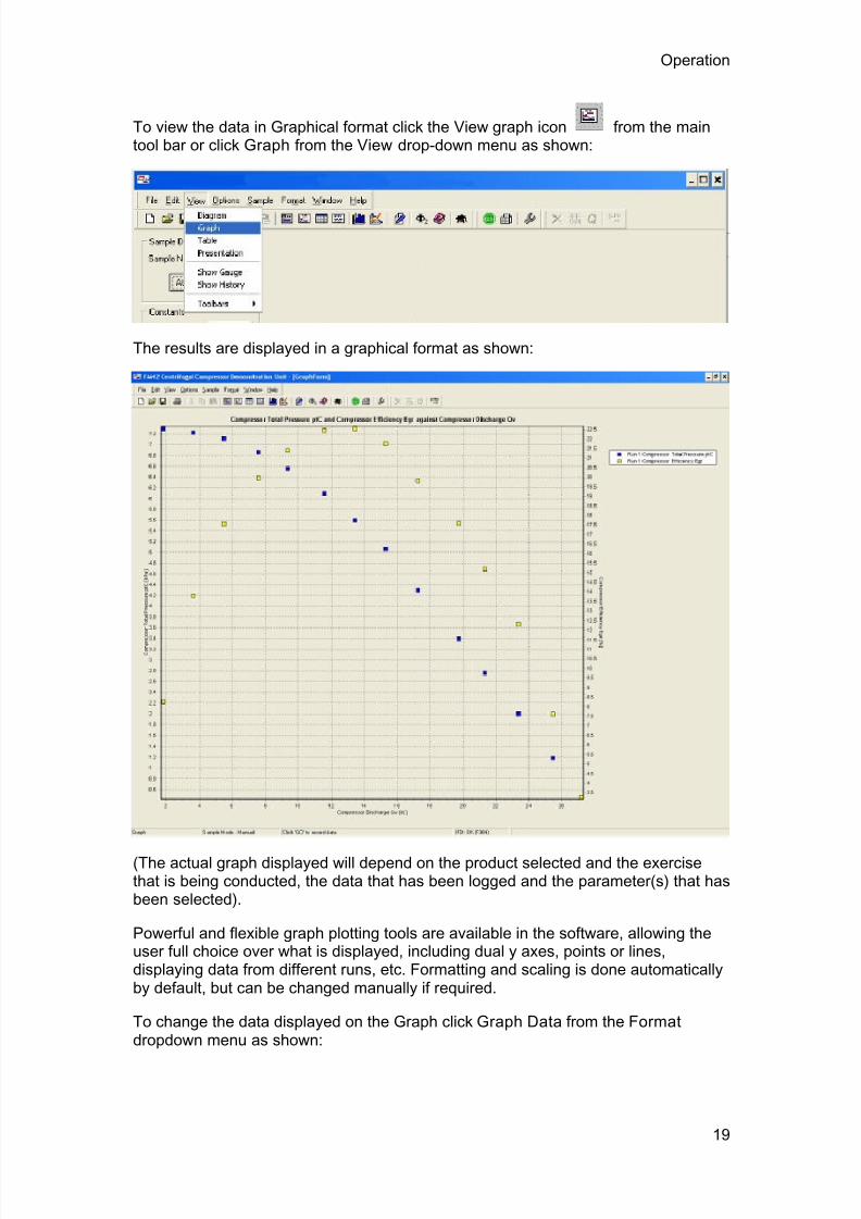
To view the data in Graphical format click the View graph icon from the maintool bar or click Graph from the View drop-down menu as shown:
The results are displayed in a graphical format as shown:
(The actual graph displayed will depend on the product selected and the exercisethat is being conducted, the data that has been logged and the parameter(s) that hasbeen selected).
Powerful and flexible graph plotting tools are available in the software, allowing theuser full choice over what is displayed, including dual y axes, points or lines,displaying data from different runs, etc. Formatting and scaling is done automaticallyby default, but can be changed manually if required.
To change the data displayed on the Graph click Graph Data from the Format dropdown menu as shown:
19

7/23/2019 HT33 Instruction Manual Issue 14
http://slidepdf.com/reader/full/ht33-instruction-manual-issue-14 24/70
Armfield Instruction Manual
The available parameters (Series of data) are displayed in the left hand pane asshown:
Two axes are available for plotting, allowing series with different scaling to bepresented on the same x axis.
To select a series for plotting, click the appropriate series in the left pane so that it ishighlighted then click the appropriate right-facing arrow to move the series into one ofthe windows in the right hand pane. Multiple series with the same scaling can beplotted simultaneously by moving them all into the same window in the right pane.
To remove a series from the graph, click the appropriate series in the right pane sothat it is highlighted then click the appropriate left-facing arrow to move the series intothe left pane.
The X-Axis Content is chosen by default to suit the exercise. The content can bechanged if appropriate by opening the drop down menu at the top of the window.
The format of the graphs, scaling of the axes etc. can be changed if required byclicking Graph in the Format drop-down menu as shown:
20

7/23/2019 HT33 Instruction Manual Issue 14
http://slidepdf.com/reader/full/ht33-instruction-manual-issue-14 25/70
Operation
For more detailed information about changing these settings refer to the Help available via the upper toolbar when operating the software.
PID Control
Where appropriate, the software associated with some products will include a singleor multiple PID control loops whereby a function on the product can be manually orautomatically controlled using the PC by measuring an appropriate variable andvarying a function such as a heater power or pump speed.
The PID loop can be accessed by clicking the box labelled PID or Control dependingon the particular software:
A PID screen is then displayed as shown:
21

7/23/2019 HT33 Instruction Manual Issue 14
http://slidepdf.com/reader/full/ht33-instruction-manual-issue-14 26/70
Armfield Instruction Manual
The Mode of operation always defaults to Manual control and 0% output when thesoftware is loaded to ensure safe operation of the equipment. If appropriate, theoperator can retain manual operation and simply vary the value from 0 to 100% in theManual Output box, then clicking Apply.
Alternatively, the PID loop can be changed to Automatic operation by clicking the Automatic button. If any of the PID settings need to be changed from the defaultvalues then these should be adjusted individually before clicking the Apply button.
The controller can be restored to manual operation at any time by clicking the Manualbutton. The value in the Manual Output box can be changed as required beforeclicking the Apply button.
Settings associated with Automatic Operation such as the Setpoint, ProportionalBand, Integral Time, Derivative Time and Cycle Time (if appropriate) can bechanged by the operator as required before clicking the Apply button.
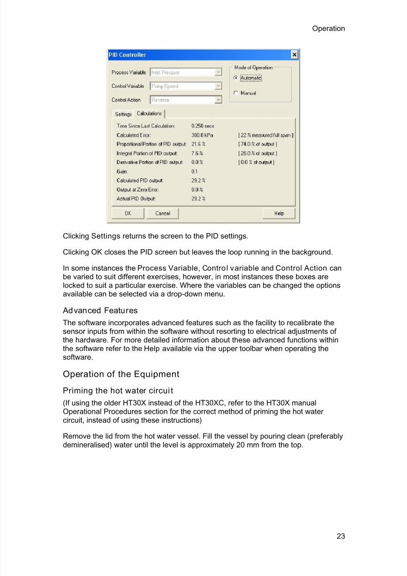
Clicking Calculations displays the calculations associated with the PID loop to aidunderstanding and optimization of the loop when changing settings as shown:
22
7/23/2019 HT33 Instruction Manual Issue 14
http://slidepdf.com/reader/full/ht33-instruction-manual-issue-14 27/70
Operation
Clicking Settings returns the screen to the PID settings.
Clicking OK closes the PID screen but leaves the loop running in the background.
In some instances the Process Variable, Contro l variable and Control Action canbe varied to suit different exercises, however, in most instances these boxes arelocked to suit a particular exercise. Where the variables can be changed the optionsavailable can be selected via a drop-down menu.
Advanced Features
The software incorporates advanced features such as the facility to recalibrate thesensor inputs from within the software without resorting to electrical adjustments ofthe hardware. For more detailed information about these advanced functions withinthe software refer to the Help available via the upper toolbar when operating thesoftware.
Operation of the Equipment
Priming the hot water circui t
(If using the older HT30X instead of the HT30XC, refer to the HT30X manualOperational Procedures section for the correct method of priming the hot watercircuit, instead of using these instructions)
Remove the lid from the hot water vessel. Fill the vessel by pouring clean (preferablydemineralised) water until the level is approximately 20 mm from the top.
23

7/23/2019 HT33 Instruction Manual Issue 14
http://slidepdf.com/reader/full/ht33-instruction-manual-issue-14 28/70
Armfield Instruction Manual
Check that the low-level indication in the software is not activated.
Check that the in-line isolating valves are both fully open.
Set the pump speed to 50% in the software and run the pump using counter-currentoperation until all air bubbles are displaced from the system into the hot water vessel.
Top up the level of this vessel as necessary to maintain the level above the tip of thelevel electrode (typically 20 mm from the top of the vessel).
24

7/23/2019 HT33 Instruction Manual Issue 14
http://slidepdf.com/reader/full/ht33-instruction-manual-issue-14 29/70
Operation
Note: Counter-current operation should always be selected when priming the hotwater side of a heat exchanger for the first time.
Setting the cold water flow rate
(If using the older HT30X instead of the HT30XC, refer to the HT30X manual
Operational Procedures section for the correct method of setting the cold water flowrate, instead of using these instructions)
The Cold Water Flow Valve can be controlled from the computer software. The valvecan be driven from 0% (fully closed), to 100% (fully open) in steps of 1%.
The actual flow rate achieved at any particular setting will be dependent on the watersupply pressure, the pressure regulator setting, and the losses through the particular
heat exchanger in use. This flow rate is measured by a flow meter and displayed inlitres/min on the computer screen.
In normal use, the valve setting is adjusted until the desired flow rate is achieved.
Setting the hot water flow rate and direction
The hot water flow rate can be controlled from the computer software by varying the
rotational speed of the re-circulation pump.
25

7/23/2019 HT33 Instruction Manual Issue 14
http://slidepdf.com/reader/full/ht33-instruction-manual-issue-14 30/70
Armfield Instruction Manual
Again this can be set from 0% to 100%, with the actual flow rate being measured bya flow meter and displayed in L/min on the computer screen.
The hot water flow direction is set as a default value in the Armfield Software. If acounter-current exercise is chosen, the flow is in the direction indicated by the arrowsadjacent to the two hot water connections. If a co-current exercise is chosen thedirection of rotation of the pump and therefore the flow of water is reversed.
Note: A change in the temperature of the water will affect the viscosity of the waterresulting in a small change in flowrate. It will therefore be necessary to adjust the hotwater flow control in the software if it is required to perform tests at the same flowrate
but different temperatures.
Setting the hot water flow rate and direction
(If using the older HT30X instead of the HT30XC please refer to the HT30X manualOperational Procedures section for the correct method of setting the hot water flowrate and direction, instead of using these instructions. Cocurrent or countercurrentflow is set by manually changing the plumbing of the HT30X, and cannot becontrolled from the computer software)
The hot water flow rate can be controlled from the computer software by varying therotational speed of the re-circulation pump.
Again this can be set from 0% to 100%, with the actual flow rate being measured bya flow meter and displayed in L/min on the computer screen.
The hot water flow direction is set as a default value in the Armfield Software. If a
counter-current exercise is chosen, the flow is in the direction indicated by the arrowsadjacent to the two hot water connections. If a co-current exercise is chosen thedirection of rotation of the pump and therefore the flow of water is reversed.
Note: A change in the temperature of the water will affect the viscosity of the waterresulting in a small change in flowrate. It will therefore be necessary to adjust the hotwater flow control in the software if it is required to perform tests at the same flowratebut different temperatures.
Setting the hot water temperature
(If using the older HT30X instead of the HT30XC, refer to the HT30X manualOperational Procedures section for the correct method of setting the hot water
temperature, instead of using these instructions)
26
7/23/2019 HT33 Instruction Manual Issue 14
http://slidepdf.com/reader/full/ht33-instruction-manual-issue-14 31/70
Operation
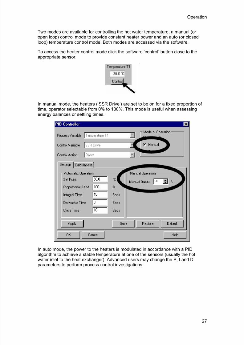
Two modes are available for controlling the hot water temperature, a manual (oropen loop) control mode to provide constant heater power and an auto (or closedloop) temperature control mode. Both modes are accessed via the software.
To access the heater control mode click the software ‘control’ button close to theappropriate sensor.
In manual mode, the heaters (‘SSR Drive’) are set to be on for a fixed proportion oftime, operator selectable from 0% to 100%. This mode is useful when assessingenergy balances or settling times.
In auto mode, the power to the heaters is modulated in accordance with a PIDalgorithm to achieve a stable temperature at one of the sensors (usually the hotwater inlet to the heat exchanger). Advanced users may change the P, I and Dparameters to perform process control investigations.
27

7/23/2019 HT33 Instruction Manual Issue 14
http://slidepdf.com/reader/full/ht33-instruction-manual-issue-14 32/70
Armfield Instruction Manual
Measuring the water temperatures and flow rates
(If using the older HT30X instead of the HT30XC, and not using the HT30X software,then refer to the HT30X manual Operational Procedures section for the correctmethod of measuring the water temperatures and flow rates instead of using these
instructions)
The temperature of the hot and cold fluids at the fluid inlet and outlet are measuredusing type ‘k’ thermocouples. The outputs from these sensors are displayed on thesoftware mimic diagram screen, calibrated in °C. Sensor outputs may be monitored
in X-Y graph format in real time by selecting the icon or bar graph format by
selecting the icon. A snapshot of the sensor outputs may also be sent to a results
table by selecting the icon and plotted on a graph via the icon, and maythen be saved in native .vts format for later reference within the Armfield software, orexported in another spreadsheet format such as Microsoft™ Excel™ (not provided by Armfield).
The hot and cold flow rates are monitored using turbine-type flow sensors, calibratedin litres per minute. The outputs from these sensors may be monitored, logged andsaved as for the temperature sensor outputs.
Effect of cold water temperature on heat exchange
The temperature of the water entering the equipment from the mains cold watersupply will affect the range of range of hot and cold water flowrates and/or thetemperature of the hot water that can be achieved when using the equipment.
The heater in the hot water circulator has a nominal rating of 2 kW, limiting the heat
exchange from the hot water stream to the cold water stream to this value. If thetemperature of the hot water will not reach the value set on the PID controller with the
28

7/23/2019 HT33 Instruction Manual Issue 14
http://slidepdf.com/reader/full/ht33-instruction-manual-issue-14 33/70
Operation
controller providing full power to the heater then this indicates that the limit of theheater power has been reached. This is not a problem and simply requires anadjustment to the settings on the equipment.
To operate with the same flowrates then a lower hot water temperature must beaccepted (reduced differential temperature between the two fluid streams). Tooperate with an elevated hot water temperature then one or both of the flowratesmust be reduced until the demand on the heater is less than 2 kW.
Some of the settings in the practical training exercises may be affected in this way. An excessively warm mains water supply will not present any problems since thetemperature difference between the two fluid streams will be reduced. This wouldallow the hot water stream to be increased to even higher temperatures than quoted. An excessively cold mains water supply may mean that the hot water temperaturequoted cannot be achieved because of the increased temperature differencebetween the two fluid streams. Operation at reduced hot water temperature orreduced flowrate must then be accepted.
Operation of Guest push fittings
Guest push fittings are used on the equipment for convenience when changing theconfiguration or removing items for cleaning. The diagrams below show the simpleoperation of these fittings:
To connect to a quick release fitting
Align the parallel section of the rigid tube with the loose collet on the quick releasefitting…
and push firmly until the tube stops.
An 'O' ring inside the fitting provides a leak-proof seal between the tube and thefitting. The collet grips the tube and prevents it from being pulled out from the fitting.
To disconnect from a quick release fitting
Push the loose collet against the body of the quick release fitting while pulling thetube firmly.
29

7/23/2019 HT33 Instruction Manual Issue 14
http://slidepdf.com/reader/full/ht33-instruction-manual-issue-14 34/70
Armfield Instruction Manual
The tube will slide out from the fitting. The tube/fitting can be assembled anddisassembled repeatedly without damage.
30

7/23/2019 HT33 Instruction Manual Issue 14
http://slidepdf.com/reader/full/ht33-instruction-manual-issue-14 35/70
31
Equipment Specifications
I/O Port Pin Connections
To allow access to the measurement signals in applications from the HT30X, otherthan when using an Armfield interface device, the connections to the 50 wayconnector are listed below for information:
Pin No Channel No Signal Function
Analog Inputs (0-5 V dc):
1 Ch 0 Temperature 1 (0-200°C)
2 Ch 1 Temperature 2 (0-200°C)
3 Ch 2 Temperature 3 (0-200°C)
4 Ch 3 Temperature 4 (0-200°C)
5 Ch 4 Temperature 5 (0-200°C)
6 Ch 5 Temperature 6 (0-200°C)
7 Ch 6 Temperature 7 (0-200°C)
8 Ch 7 Temperature 8 (0-200°C)
9 Ch 8 Temperature 9 (0-200°C)
10 Ch 9 Temperature 10 (0-200°C)
11 Ch 10 Flow F1 (0-3 L/min)
12 Ch 11 Flow F2 (0-1.5 L/min)
13-21 Not used
Analog Outputs (0-5V dc):
22 Not used
23 Ch 0 Hot water pump speed
24 Ch 1 Cold water valve setting
25 Not used

7/23/2019 HT33 Instruction Manual Issue 14
http://slidepdf.com/reader/full/ht33-instruction-manual-issue-14 36/70
Armfield Instruction Manual
Digital Inputs (0-5V dc):
26-27 Not Used
30 Ch 2 Level Monitor
21-32 Not used
33 Ch 4 Thermostat Monitor
34-37 Not used
Digital Outputs (0-5V dc):
38 Ch 0 Power On
39 Ch 1 Watchdog pulse
40 Ch 2 SSR drive
41 Ch 3 Pump direction
42 Digital Ground
43 Ch 4 Stirrer on
44 Ch 5 Aux heater on
47-48 Digital Ground
49-50 Not Used
USB Channel Numbers
To allow access to the measurement signals in applications other than the Armfieldsoftware when using the HT30XC, Armfield have provided a USB driver with the
software installation disk. Armfield does not provide alternative software orinstructions on using alternative software. The channel numbers for the USB port arelisted below:
Channel No Signal Function
Analog Inputs (0-5 V dc):
Channel 0 Temperature T1 (0-133°C = -5 to +5 V)
Channel 1 Temperature T2 (0-133°C = -5 to +5 V)
32

7/23/2019 HT33 Instruction Manual Issue 14
http://slidepdf.com/reader/full/ht33-instruction-manual-issue-14 37/70
Equipment Specifications
Channel 2 Temperature T3 (0-133°C = -5 to +5 V)
Channel 3 Temperature T4 (0-133°C = -5 to +5 V)
Channel 4 Temperature T5 (0-133°C = -5 to +5 V)
Channel 5 Temperature T6 (0-133°C = -5 to +5 V)
Channel 6 Temperature T7 (0-133°C = -5 to +5 V)
Channel 7 Temperature T8 (0-133°C = -5 to +5 V)
Channel 8 Temperature T9 (0-133°C = -5 to +5 V)
Channel 9 Temperature T10 (0-133°C = -5 to +5 V)
Channel 10 Hot water flow Fhot (0-25 L/min = 0-5 V)
Channel 11 Cold water flow Fcold (0-25 L/min = 0-5 V)
Analog Outputs (0-5V dc):
Channel 0 Hot water pump speed
Channel 1 Cold water valve setting
Digital Inputs (0-5V dc):
Channel 0 Not Used
Channel 1 Not used
Channel 2 Level Monitor
Channel 4 Thermostat Monitor
Digital Outputs (0-5V dc):
Channel 0 Power On required (1 = on)
Channel 1 Watchdog pulse ( 1 pulse every 5 secs)
Channel 2 SSR (heater) drive (1 = on)
Channel 3 Pump direction (1 = cocurrent)
Environmental Conditions
This equipment has been designed for operation in the following environmentalconditions. Operation outside of these conditions may result reduced performance,damage to the equipment or hazard to the operator.
33

7/23/2019 HT33 Instruction Manual Issue 14
http://slidepdf.com/reader/full/ht33-instruction-manual-issue-14 38/70
Armfield Instruction Manual
a. Indoor use;
b. Altitude up to 2000 m;
c. Temperature 5 °C to 40 °C;
d. Maximum relative humidity 80 % for temperatures up to 31 °C, decreasinglinearly to 50 % relative humidity at 40 °C;
e. Mains supply voltage fluctuations up to ±10 % of the nominal voltage;
f. Transient over-voltages typically present on the MAINS supply;
Note: The normal level of transient over-voltages is impulse withstand (over-voltage) category II of IEC 60364-4-443;
g. Pollution degree 2.
Normally only nonconductive pollution occurs.
Temporary conductivity caused by condensation is to be expected.
Typical of an office or laboratory environment
34

7/23/2019 HT33 Instruction Manual Issue 14
http://slidepdf.com/reader/full/ht33-instruction-manual-issue-14 39/70
35
Routine Maintenance
Responsibility
To preserve the life and efficient operation of the equipment it is important that theequipment is properly maintained. Regular maintenance of the equipment is the
responsibility of the end user and must be performed by qualified personnel whounderstand the operation of the equipment.
General
In addition to regular maintenance the following notes should be observed:
1. The HT30X/HT30XC service unit should be disconnected from the electricaland water supplies when not in use.
2. Water should be drained from the inner tubes and outer annulus of the HT33heat exchanger after use to minimise build up of scale or fouling on the heat
exchange surfaces.
The water can be drained by simply disconnecting the four flexible tubesconnecting the exchanger to the HT30X/HT30XC service unit.
3. Any build up of scale inside the heat exchanger can be removed by passing amild descaler through the exchanger then flushing thoroughly with cleanwater.
Any stubborn deposits can be eliminated by manual cleaning having carefullyremoved the inner tube from the outer annulus. To remove the metal tube forcleaning, disconnect the quick release fittings from each end of the metal tubethen pull the tube out of the assembly taking care not to damage the 'O' ringseals. After cleaning, lubricate the 'O' ring seals with a small amount ofwetting agent before re-inserting the metal tube and replacing the quickrelease fittings.
Note: The PVC housing at each end of the acrylic tube is bonded to theacrylic tube and cannot be removed.
If it is necessary to replace the 'O' ring seals the replacements should have thefollowing specification:
Material Nitrile rubber
Diameter To suit 3/8" shaft
Section 0.103" section
For reference the Dowty part number is 200-110-4470

7/23/2019 HT33 Instruction Manual Issue 14
http://slidepdf.com/reader/full/ht33-instruction-manual-issue-14 40/70
Laboratory Teaching Exercises
Index to Exercises
Exercise A - Fluid to Fluid Heat Transfer
Exercise B - Energy Balance and Overall Efficiency
Exercise C - Cocurrent and Countercurrent Flow
Exercise D - Overall Heat Transfer Coefficient
Exercise E - Effect of Flow Rate
Exercise F - Driving Force
Exercise G - Project Work
NomenclatureName Symbol SI Unit
ID of tube d i m
OD of tube do m
Arithmetic mean diameter of tube dm m
Heat transmission length L m
Heat transfer area A m2
Specific Heat Capacity hot fluid Cphot kJ/kg°K
Specific Heat Capacity cold fluid Cpcold kJ/kg°K
Hot fluid inlet temperature T1 °C
Hot fluid outlet temperature T2 °C
Cold fluid inlet temperature T3 °C
Cold fluid outlet temperature T4 °C
Decrease in hot fluid temperature °C
Increase in cold fluid temperature °C
Driving force, hot fluid inlet °C
36

7/23/2019 HT33 Instruction Manual Issue 14
http://slidepdf.com/reader/full/ht33-instruction-manual-issue-14 41/70
Laboratory Teaching Exercises
Driving force, hot fluid outlet °C
Logarithmic Mean Temperature Difference °C
Volume flowrate (hot fluid) qvhot m3/s
Volume flowrate (cold fluid) qvcold m3/s
Density of hot fluid hot kg/m3
Density of cold fluid cold kg/m3
Mass flow rate hot fluid qmhot kg/s
Mass flow rate cold fluid qmcold kg/s
Heat power emitted from hot fluid Qe W
Heat power absorbed by cold fluid Qa W
Heat power lost (or gained) Qf W
Overall Efficiency %
Temperature Efficiency hot fluid hot %
Temperature Efficiency cold fluid cold %
Mean Temperature Efficiency mean %
Overall Heat Transfer Coefficient U W/m2°C
37

7/23/2019 HT33 Instruction Manual Issue 14
http://slidepdf.com/reader/full/ht33-instruction-manual-issue-14 42/70
Armfield Instruction Manual
Reference Tables
Table 1: Specific Heat Capacity of Water (Cp kJ/kg°K)
Table 2: Density o f Water ( kg/m3)
38

7/23/2019 HT33 Instruction Manual Issue 14
http://slidepdf.com/reader/full/ht33-instruction-manual-issue-14 43/70
39
Exercise A: Fluid to Fluid Heat Transfer
Objective
To demonstrate indirect heating or cooling by transfer of heat from one fluid streamto another when separated by a solid wall (fluid to fluid heat transfer).
Method
By measuring the changes in temperature of two separate streams of water flowingthrough the inner tube bundle and outer shell of a shell and tube heat exchanger.
Equipment Required
HT30X/HT30XC Heat Exchanger Service Unit
HT33 Shell and Tube Heat Exchanger
Equipment set-up
Before proceeding with the exercise ensure that the equipment has been set up andthe accessory installed as described in this manual, with a cold water supplyconnected and the pressure regulator adjusted. The apparatus should be switchedon, and if using the HT30XC the service unit should be connected to a suitable PCon which the software has been installed. Computer operation is optional with theHT30X.
Prime the hot and cold water circuits using the cold water supply (Refer to theOperation section if you need details on how to prime the equipment).
If using the HT30XC, or the HT30X with the optional software, run the HT33 softwarefor the service unit used (HT30XC software must be used with the HT30XC and
HT30X software with the HT30X, as the calibration for the sensors differs betweenthe two service units). If using the HT30XC, select the Countercurrent exercise. Ifusing the HT30X, select Exercise A and then select Countercurrent Operation on thesoftware display option box.
Theory/Background
Any temperature difference across the metal tube wall will result in the transfer ofheat between the two fluid streams. The hot water flowing through the inner tubebundle will be cooled and the cold water flowing through the outer shell will beheated.
Note: For this demonstration the heat exchanger is configured with the two streamsflowing in opposite directions (countercurrent flow). The cold fluid flowing through theshell is forced to flow over and under baffles in the shell which force the fluid to flowacross the tube bundle to improve the heat exchange.

7/23/2019 HT33 Instruction Manual Issue 14
http://slidepdf.com/reader/full/ht33-instruction-manual-issue-14 44/70
Armfield Instruction Manual
Procedure
(Refer to the Operation section if you need details of the instrumentation and how tooperate it. The mains supply should be switched on before starting this experiment.)
Set the temperature controller to 60oC. If using the HT30X then switch on the hot
water circulator.
Adjust the cold water control valve setting to give a cold water flow rate of 1 litre/min.
If using HT30X, adjust the hot water control valve setting Vhot to give a hot waterflow of 3 litres/min. If using HT30XC, click on the button for the hot water flow ratecontroller, set the controller to Automatic and enter a Set Point value of 3 litres/min. Apply and click ‘OK’.
Allow the temperatures to stabilise (monitor the temperatures using the sensordisplay on the software screen or control console).
When the temperatures are stable select the icon to record the following, ormanually note the values: T1, T2, T3, T4, F hot, Fcold.
Adjust the cold water control valve to give 2 litres/min.
Allow the heat exchanger to stabilise then repeat the above readings.
If using the software, save the logged data by selecting ‘Save’ or ‘Save As’ from the‘File’ menu. Browse to the location you wish to place the saved data and give theresults a meaningful name (e.g. HT33A).
Results and Calculations
The software records all sensor outputs and also calculates several derived figures,and presents the recorded data in tabular form. The following columns are relevant tothis exercise, and are suggested as suitable column headings if recording valuesmanually:
Hot fluid volume flowrate qvhot (m3/s) Multiply Fhot (litres/min) by 1.667x10⁻⁵
Hot fluid inlet temperature T1 (°C)
Hot fluid outlet temperature T2 (°C)
Cold fluid volume flowrate qvcold (m3
/s) Multiply Fcold (litres/min) by 1.667x10⁻⁵
Cold fluid inlet temperature T3 (°C)
Cold fluid outlet temperature T4 (°C)
You should also estimate and record the experimental errors for thesemeasurements.
For each set of readings, the relevant derived results are calculated and presented
with the following headings:
40

7/23/2019 HT33 Instruction Manual Issue 14
http://slidepdf.com/reader/full/ht33-instruction-manual-issue-14 45/70
Exercise A
Reduction in hot fluid temperature (°C)
Increase in cold fluid temperature (°C)
These values should be calculated manually if not using the software.
A graph may be plotted of the results. The software graph facility may be used forthis.
Estimate the cumulative influence of the experimental errors on your calculated
values for and .
Compare the changes in temperature at the different flowrates. If time permits trydifferent combinations of hot and cold fluid flowrate.
Conclusion
You have demonstrated how, using a simple shell and tube heat exchanger, astream of cold fluid can be heated by indirect contact with another fluid stream at ahigher temperature (the fluid streams being separated by a wall which conductsheat). This transfer of heat results in a cooling of the hot fluid.
Comment on the changes in and when the flow of cold water isincreased. The consequence of these changes will be investigated in a laterexercise.
Note: To save time Exercise B can be carried out using the readings obtained fromthis exercise.
41

7/23/2019 HT33 Instruction Manual Issue 14
http://slidepdf.com/reader/full/ht33-instruction-manual-issue-14 46/70
42
Exercise B: Energy Balance and Overall Efficiency
Objective
To perform an energy balance across a Shell and Tube Heat Exchanger andcalculate the Overall Efficiency at different fluid flowrates.
Method
By measuring the changes in temperature of the two separate fluid streams in a shelland tube heat exchanger and calculating the heat energy transferred to/from eachstream to determine the Overall Efficiency.
Equipment Required
As Exercise A.
Equipment set-up
If using the results from Exercise A then the equipment is not required.
If previous results are not available refer to the Set-up and Procedure sections ofExercise A.
Theory/Background
Note: For this demonstration the heat exchanger is configured for countercurrentflow (the two fluid streams flowing in opposite directions).
Mass flowrate (qm) = Volume flowrate (qv)
x Density of fluid () (kg/s)
Heat power (Q) = Mass flowrate (qm) x specific heat (Cp)
x change in temperature (W)
Therefore:
Heat power emitted from hot fluid Qe = qmh. Cph (T1 - T2) (W)
Heat power absorbed by cold fluid Qa = qmc . Cpc (T4 - T3) (W)
Heat power lost (or gained) Qf = Qe - Qa (W)
Overall Efficiency (%)

7/23/2019 HT33 Instruction Manual Issue 14
http://slidepdf.com/reader/full/ht33-instruction-manual-issue-14 47/70
Exercise B
Theoretically Qe and Qa should be equal. In practice these differ due to heat lossesor gains to/from the environment.
Note: In this exercise the cold fluid is circulated through the outer shell, if theaverage cold fluid temperature is above the ambient air temperature then heat will be
lost to the surroundings resulting in <100%. If the average cold fluid temperature is
below the ambient temperature then heat will be gained resulting in >100%.
Procedure
Use the results obtained from Exercise A.
Results and Calculations
The software records all sensor outputs and also calculates several derived figures,and presents the recorded data in tabular form. The following columns are relevant tothis exercise, and are suggested as suitable column headings if recording valuesmanually:
Hot fluid volume flowrate qvhot (m3/s) Multiply Fhot (litres/min) by 1.667x10⁻⁵
Hot fluid inlet temperature T1 (°C)
Hot fluid outlet temperature T2 (°C)
Cold fluid volume flowrate qvcold (m3/s) Multiply Fcold (litres/min) by 1.667x10⁻⁵
Cold fluid inlet temperature T3 (°C)
Cold fluid outlet temperature T4 (°C)
You should also estimate and record the experimental errors for thesemeasurements.
For each set of readings, the software calculates the average hot fluid temperature(from T1 and T2) and the average cold fluid temperature (from T3 and T4) and thenautomatically provides values for the following variables. If recording data manually,calculate these values and obtain the variables from the Reference Tables:
Specific heat of hot fluid Cph kJ/kgoK (From table 1)
Specific heat of cold fluid Cpc kJ/kgoK (From table 1)
Density of hot fluid h kg/m3 (From table 2)
Density of cold fluid c kg/m3 (From table 2)
For each set of readings, the relevant derived results are calculated and presentedwith the following headings:
43

7/23/2019 HT33 Instruction Manual Issue 14
http://slidepdf.com/reader/full/ht33-instruction-manual-issue-14 48/70
Armfield Instruction Manual
Mass flowrate (hot fluid) qmh (kg/s)
Mass flowrate (cold fluid) qmc (kg/s)
Heat power emitted Qe (W)
Heat power absorbed Qa (W)
Heat power lost Q f (W)
Overall Efficiency (%)
These values should be calculated manually if not using the software.
A graph may be plotted of the results. The software graph facility may be used for
this.
Estimate the cumulative influence of the experimental errors on your calculated
values for Qe, Qa, Qf and .
Compare the heat power emitted from/absorbed by the two fluid streams at thedifferent flowrates.
Conclusions
Explain any difference between Qe and Qa in your results.
Comment on the effects of the increase in the cold fluid flowrate.
Exercise C should be carried out on completion of this exercise.
44
7/23/2019 HT33 Instruction Manual Issue 14
http://slidepdf.com/reader/full/ht33-instruction-manual-issue-14 49/70
45
Exercise C: Cocurrent and Countercurrent Flow
Objective
To demonstrate the differences between cocurrent flow (flows in same direction) andcountercurrent flow (flows in the opposite direction) and the effect on heat transferred
and temperature efficiencies.
Method
By measuring the temperatures of the two fluid streams and using the temperaturechanges and differences to calculate the heat energy transferred and thetemperature efficiencies.
Equipment Required
HT30X/HT30XC Heat Exchanger Service Unit
HT33 Shell and Tube Heat Exchanger
Equipment set-up
Before proceeding with the exercise ensure that the equipment has been set up andthe accessory installed as described in this manual, with a cold water supplyconnected and the pressure regulator adjusted. The apparatus should be switchedon, and if using the HT30XC the service unit should be connected to a suitable PCon which the software has been installed. Computer operation is optional with theHT30X.
Prime the hot and cold water circuits using the cold water supply (Refer to theOperational Procedures in the Operation section if you need details on how to primethe equipment).
If using the HT30XC, or the HT30X with the optional software, run the HT33 softwarefor the service unit used (HT30XC software must be used with the HT30XC andHT30X software with the HT30X, as the calibration for the sensors differs betweenthe two service units). If using the HT30XC, select the Countercurrent exercise. Ifusing the HT30X, select Exercise C and then select Countercurrent Operation on thesoftware display option box.
Theory/Background
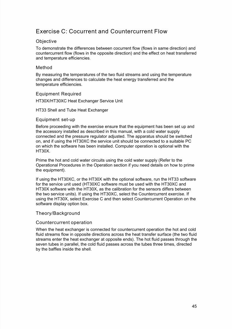
Countercurrent operation
When the heat exchanger is connected for countercurrent operation the hot and coldfluid streams flow in opposite directions across the heat transfer surface (the two fluidstreams enter the heat exchanger at opposite ends). The hot fluid passes through theseven tubes in parallel, the cold fluid passes across the tubes three times, directedby the baffles inside the shell.

7/23/2019 HT33 Instruction Manual Issue 14
http://slidepdf.com/reader/full/ht33-instruction-manual-issue-14 50/70
Armfield Instruction Manual
From the previous exercises:
Reduction in hot fluid temperature (oC)
Increase in cold fluid temperature (oC)
Heat power emitted from hot fluid Qe = qmh. (Cp)h (T1 - T2) (W)
A useful measure of the heat exchanger performance is the temperature efficiency of
each fluid stream. The temperature change in each fluid stream is compared with themaximum temperature difference between the two fluid streams giving a comparisonwith an exchanger of infinite size.
Temperature efficiency for hot fluid (%)
Temperature efficiency for cold fluid (%)
Mean Temperature Efficiency (%)
Cocurrent operation
When the heat exchanger is connected for cocurrent operation the hot and cold fluidstreams flow in the same direction across the heat transfer surface (the two fluidstreams enter the heat exchanger at the same end).
46

7/23/2019 HT33 Instruction Manual Issue 14
http://slidepdf.com/reader/full/ht33-instruction-manual-issue-14 51/70
Exercise C
From the previous exercises:
Reduction in hot fluid temperature (°C)
Increase in cold fluid temperature (oC)
Heat power emitted from hot fluid Qe = qmh. (Cp)h (T2 – T1) (W)
Temperature efficiency for hot fluid (%)
Temperature efficiency for cold fluid (%)
Mean Temperature Efficiency (%)
Procedure
(Refer to the Operation section if you need details of the instrumentation and how to
operate it. The mains supply should be switched on before starting this experiment.)
Set the temperature controller to 60oC. If using the HT30X then switch on the hotwater circulator.
Adjust the cold water control valve setting to give a cold water flow rate of 1 litre/min.
If using HT30X, adjust the hot water control valve setting Vhot to give a hot waterflow of 2 litres/min. If using HT30XC, click on the button for the hot water flow ratecontroller, set the controller to Automatic and enter a Set Point value of 2 litres/min.‘Apply’ and select ‘OK’.
Allow the temperatures to stabilise (monitor the temperatures using the sensordisplay on the software screen or control console).
47

7/23/2019 HT33 Instruction Manual Issue 14
http://slidepdf.com/reader/full/ht33-instruction-manual-issue-14 52/70
Armfield Instruction Manual
When the temperatures are stable select the icon to record the following, ormanually note the values: T1, T2, T3, T4, F hot, Fcold
Close the cold water flow control valve.
If using the HT30XC, save the logged data by selecting ‘Save’ or ‘Save As’ from the‘File’ menu. Browse to the location you wish to place the saved data and give theresults a meaningful name (e.g. HT33C Countercurrent Operation). If using HT30X
software, create a new results sheet using the icon.
Change the system to cocurrent operation:
If using the HT30X, select the ‘Cocurrent’ radio button on the software mimicdiagram, and change the connections to the hot water inlet and outlet as follows:
If using the HT30XC, select ‘Load New Experiment...’ from the ‘File’ menu, clickingon the Cocurrent Operation exercise radio button then select the ‘Load’ button.
The connections to the heat exchanger are now configured for cocurrent operationwhere the hot and cold fluid streams flow in the same direction across the heattransfer surface (the two fluid streams enter the heat exchanger at the same end).
Adjust the cold water flow control valve to give a cold water flow rate reading of 1litre/min (Hot and cold water flowrates the same as before).
When the temperatures are stable select the icon to record the following, ormanually note the values: T1, T2, T3, T4, F hot, Fcold
48

7/23/2019 HT33 Instruction Manual Issue 14
http://slidepdf.com/reader/full/ht33-instruction-manual-issue-14 53/70
Exercise C
If using the software, save the logged data by selecting ‘Save’ or ‘Save As’ from the‘File’ menu. Browse to the location you wish to place the saved data and give theresults a meaningful name (e.g. HT33C Cocurrent Operation).
Results and Calculations
The software records all sensor outputs and also calculates several derived figures,and presents the recorded data in tabular form. The following columns are relevant tothis exercise, and are suggested as suitable column headings if taking readingsmanually:
Hot fluid volume flowrate qvhot (m3/s)Multiply Fhot (litres/min) by1.667x10-5
Hot fluid inlet temperature T1 (°C)
Hot fluid outlet temperature T2 (°C)
Cold fluid volume flowrate qvcold (m3/s)Multiply Fhot (litres/min) by1.667x10-5
Cold fluid inlet temperaturecountercurrent flow
T3 (°C)
Cold fluid outlet temperaturecountercurrent flow
T4 (°C)
Note: In cocurrent flow T2 is the hot fluid outlet temperature and T1 is the hot fluidinlet temperature.
You should also estimate the experimental errors for these measurements.
For each set of readings, the software calculates the average hot fluid temperature(from T1 and T2) and the average cold fluid temperature (from T3 and T4) and thenautomatically provides values for the following variables. If recording data manually,calculate these values and obtain the variables from the Reference Tables:
Specific heat of hot fluid Cph kJ/kgoK (From table 1)
Density of hot fluid h kg/m
3
(From table 2)
For each set of readings, the relevant derived results are calculated and presentedwith the following headings:
Reduction in hot fluid temperature (oC)
Increase in cold fluid temperature (oC)
Heat power emitted from hot fluid Qe (W)
Temperature efficiency for hot fluid h (%)
49

7/23/2019 HT33 Instruction Manual Issue 14
http://slidepdf.com/reader/full/ht33-instruction-manual-issue-14 54/70
Armfield Instruction Manual
Temperature efficiency for cold fluid c (%)
Mean temperature efficiency m (%)
These values should be calculated manually if not using the software.
Estimate the cumulative influence of the experimental errors on your calculatedvalues for each of the above temperature differences and efficiencies.
Compare each set of calculated values.
Conclusion
Your results from this exercise should indicate clearly the basic differences betweenCocurrent and Countercurrent flow through the shell and tube heat exchanger. Theselection of the best arrangement for a particular application depends on many
parameters such as Overall Heat Transfer Coefficient, Logarithmic MeanTemperature Difference, Fluid flowrate etc. These will be explained and investigatedin later exercises.
Comment on the change in and when the heat exchanger is convertedfrom cocurrent to countercurrent operation.
Comment on the differences between the hot and cold fluid temperature efficiency forany given configuration and explain the changes in efficiency when the configurationis changed from cocurrent to countercurrent operation.
Note: To save time Exercise D can be carried out using the readings obtained from
this exercise.
50

7/23/2019 HT33 Instruction Manual Issue 14
http://slidepdf.com/reader/full/ht33-instruction-manual-issue-14 55/70
51
Exercise D: Overall Heat Transfer Coefficient
Objective
To determine the Overall Heat Transfer Coefficient for a Tubular Heat Exchangerusing the Logarithmic Mean Temperature Difference to perform the calculations (for
cocurrent and countercurrent flow).
Method
By measuring the temperatures of the two fluid streams and calculating the LMTDfrom which the overall heat transfer coefficient can be calculated for each flowconfiguration.
Equipment Required
As Exercise C.
Equipment set-up
If using the results from Exercise C then the equipment is not required.
If previous results are not available refer to the Set-up and Procedure sections ofExercise C.
Theory/Background
Countercurrent operation
Cocurrent operation
Heat power emitted from hot fluid Qe = qmh. (Cp)h (T1 - T2) (W)
Note: To eliminate the effect of heat losses/gains in the cold water stream the heatemitted from the hot fluid stream will be used in the calculations.

7/23/2019 HT33 Instruction Manual Issue 14
http://slidepdf.com/reader/full/ht33-instruction-manual-issue-14 56/70
Armfield Instruction Manual
Because the temperature difference between the hot and cold fluid streams variesalong the length of the heat exchanger it is necessary to derive an averagetemperature difference (driving force) from which heat transfer calculations can beperformed. This average temperature difference is called the Logarithmic Mean
Temperature Difference (LMTD) .
where (°C)
and (oC)
Note: This equation cannot produce a result for the case where
LMTD (oC)
In this example the equation for LMTD is the same for both countercurrent andcocurrent operation.
The heat transmission area in the exchanger must be calculated using the arithmeticmean diameter of the inner tubes.
Arithmetic mean diameter (m)
Heat transmission length L = n.l (m)
where n = number of tubes = 7
l = heat transmission length of each tube = 0.144 (m)
L = 1.008
Heat transmission area = A = .dm.L (m2)
(dm can be used since r2/r1<1.5 otherwise the logarithmic mean radius d lm must be
used)
Overall Heat Transfer Coefficient (W/m2K)
Procedure
Use the results obtained from Exercise C.
Results and Calculations
Technical data:
Tube inside diameter d i = 0.00515 (m)
52

7/23/2019 HT33 Instruction Manual Issue 14
http://slidepdf.com/reader/full/ht33-instruction-manual-issue-14 57/70
Exercise D
Tube outside diameter do = 0.00635 (m)
Heat transmission length L = 1.008 (total) (m)
The software records all sensor outputs and also calculates several derived figures,and presents the recorded data in tabular form. The following columns are relevant to
this exercise, and are suggested as suitable column headings if recording datamanually:
Hot fluid volume flowrate qvhot (m3/s)Multiply Fhot (litres/min) by1.667x10-5
Hot fluid inlet temperature T1 (oC)
Hot fluid outlet temperature T2 (oC)
Cold fluid volume flowrate qvcold (m3/s)Multiply Fhot (litres/min) by
1.667x10⁻⁵
Cold fluid inlet temperaturecountercurrent flow
T3 (oC)
Cold fluid outlet temperaturecountercurrent flow
T4 (oC)
Arithmetic mean diameter dm (m)
Heat transmission area A (m2)
You should estimate the experimental errors for these measurements.
Note: In cocurrent flow T2 is the hot fluid outlet temperature and T1 is the hot fluidinlet temperature.
For each set of readings, the software calculates the average hot fluid temperature(from T1 and T2) and the average cold fluid temperature (from T3 and T4) and thenautomatically provides values for the following variables. If recording data manually,calculate these values and obtain the variables from the Reference Tables:
Specific heat of hotfluid
Cph kJ/kgoK (From table 1 using T2 as the averagetemperature)
Density of hot fluid h kg/m3 (From table 2 using T2 as the averagetemperature)
For each set of readings, the relevant derived results are calculated and presentedwith the following headings:
Temperature difference (o
C)
53

7/23/2019 HT33 Instruction Manual Issue 14
http://slidepdf.com/reader/full/ht33-instruction-manual-issue-14 58/70
Armfield Instruction Manual
Temperature difference (oC)
Mass flowrate (hot fluid) qmh (kg/s)
Heat power emitted from hot fluid Qe (W)
LMTD (oC)
Overall heat transfer coefficient U (W/m2K)
These values should be calculated manually if not using the software.
Estimate the cumulative influence of the experimental errors on your calculated
values for and U.
Conclusion
You have now been introduced to the method for calculating the Overall HeatTransfer Coefficient for a shell and tube heat exchanger. This is the most importantcharacteristic of a heat exchanger. The effect of fluid flowrates and temperaturedifferences between the hot and cold fluid streams will be investigated in laterexercises.
Comment on the differences in and when the heat exchanger is configured
for cocurrent and countercurrent flow. Comment on the resulting values for andits effect on U.
Comment on any difference between the Overall Heat Transfer Coefficient for thesame heat exchanger in cocurrent and countercurrent flow (with all other variablesthe same).
If you have conducted a similar exercise using a tubular heat exchanger (HT31 orHT36) or plate heat exchanger (HT32 or HT37) compare the performances andcomment on the differences.
Exercise E should be carried out on completion of this exercise.
54

7/23/2019 HT33 Instruction Manual Issue 14
http://slidepdf.com/reader/full/ht33-instruction-manual-issue-14 59/70
55
Exercise E: Effect of Flow Rate
Objective
To investigate the effect of changes in hot and cold fluid flowrate on the TemperatureEfficiencies and Overall Heat Transfer Coefficient.
Method
By measuring the fluid temperatures at different combinations of hot and cold fluidflowrate then calculating the corresponding Overall Heat Transfer Coefficient.
Equipment Required
HT30XC Heat Exchanger Service Unit
HT33 Shell and Tube Heat Exchanger
Equipment set-up
Before proceeding with the exercise ensure that the equipment has been set up andthe accessory installed as described in this manual, with a cold water supplyconnected and the pressure regulator adjusted. The apparatus should be switchedon, and if using the HT30XC the service unit should be connected to a suitable PCon which the software has been installed. Computer operation is optional with theHT30X.
Prime the hot and cold water circuits using the cold water supply (Refer to theOperation section if you need details on how to prime the equipment).
If using the HT30XC, or the HT30X with the optional software, run the HT33 softwarefor the service unit used (HT30XC software must be used with the HT30XC and
HT30X software with the HT30X, as the calibration for the sensors differs betweenthe two service units). If using the HT30XC, select the Countercurrent exercise. Ifusing the HT30X, select Exercise E and then select Countercurrent Operation on thesoftware display option box.
Theory/Background
Refer to Teaching Exercises C & D for details of the relevant theory relating to thecalculation of the Temperature efficiencies and Overall Heat Transfer Coefficients.
Procedure
(Refer to the Operation section if you need details of the instrumentation and how to
operate it. The mains supply should be switched on before starting this experiment.)
Set the temperature controller to 60oC. If using the HT30X then switch on the hotwater circulator.
Adjust the cold water control valve setting to give a cold water flow rate of 1 litre/min.
If using HT30X, adjust the hot water control valve setting Vhot to give a hot waterflow of 1 litre/min. If using HT30XC, click on the button for the hot water flow ratecontroller, set the controller to Automatic and enter a Set Point value of 1 litre/min.
Allow the temperatures to stabilise (monitor the temperatures using the sensor
display on the software screen or control console).

7/23/2019 HT33 Instruction Manual Issue 14
http://slidepdf.com/reader/full/ht33-instruction-manual-issue-14 60/70
Armfield Instruction Manual
When the temperatures are stable select the icon to record the following, ormanually note the values: T1, T2, T3, T4, F hot, Fcold
Repeat the above for different settings of the hot and cold fluid volume flowrate asfollows:
Fhot (litres/min) Fcold (litres/min)
2 1
3 1
2 2
1 2
1 3
If using the HT30XC, save the logged data by selecting ‘Save’ or ‘Save As’ from the‘File’ menu. Browse to the location you wish to place the saved data and give theresults a meaningful name (e.g. HT33E Countercurrent Operation). If using the
HT30X software then create a new results sheet using the icon.
Change to cocurrent operation:
If using the HT30X, select the ‘Cocurrent’ radio button on the software mimic diagram
and change the connections to the hot water inlet and outlet as follows:
56
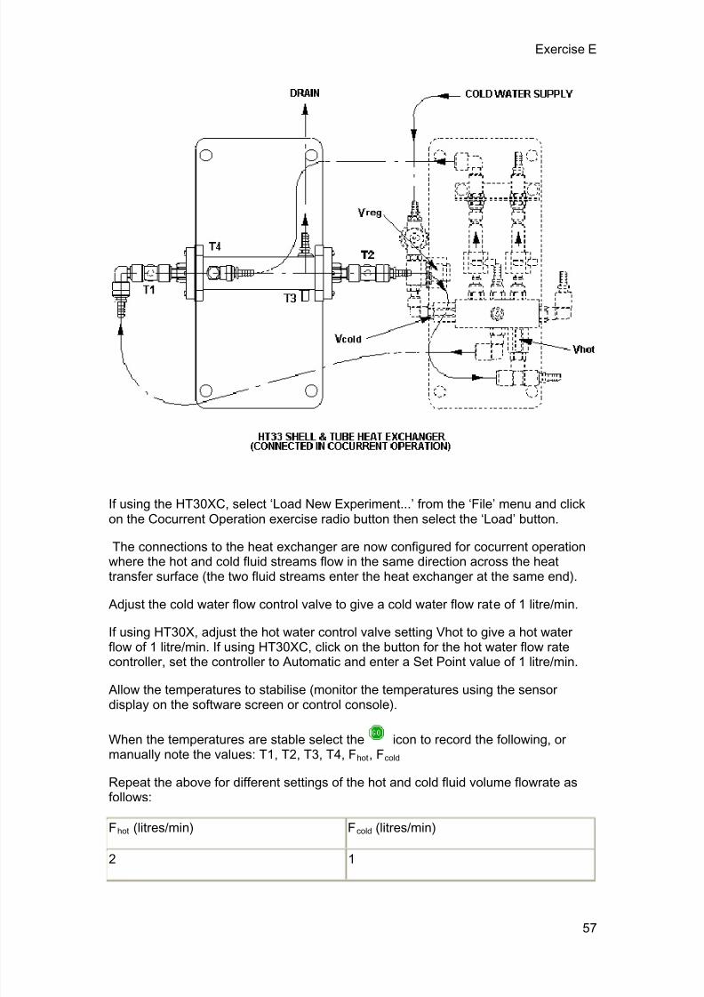
7/23/2019 HT33 Instruction Manual Issue 14
http://slidepdf.com/reader/full/ht33-instruction-manual-issue-14 61/70
Exercise E
If using the HT30XC, select ‘Load New Experiment...’ from the ‘File’ menu and click
on the Cocurrent Operation exercise radio button then select the ‘Load’ button.
The connections to the heat exchanger are now configured for cocurrent operationwhere the hot and cold fluid streams flow in the same direction across the heattransfer surface (the two fluid streams enter the heat exchanger at the same end).
Adjust the cold water flow control valve to give a cold water flow rate of 1 litre/min.
If using HT30X, adjust the hot water control valve setting Vhot to give a hot waterflow of 1 litre/min. If using HT30XC, click on the button for the hot water flow ratecontroller, set the controller to Automatic and enter a Set Point value of 1 litre/min.
Allow the temperatures to stabilise (monitor the temperatures using the sensordisplay on the software screen or control console).
When the temperatures are stable select the icon to record the following, ormanually note the values: T1, T2, T3, T4, F hot, Fcold
Repeat the above for different settings of the hot and cold fluid volume flowrate asfollows:
Fhot (litres/min) Fcold (litres/min)
2 1
57

7/23/2019 HT33 Instruction Manual Issue 14
http://slidepdf.com/reader/full/ht33-instruction-manual-issue-14 62/70
Armfield Instruction Manual
3 1
2 2
1 2
1 3
If using the HT30XC or HT30X software, save the logged data by selecting ‘Save’ or‘Save As’ from the ‘File’ menu. Browse to the location you wish to place the saveddata and give the results a meaningful name (e.g. HT33E Cocurrent Operation).
Results and Calculations
Technical data:
Inner tube inside diameter di = 0.00515 (m)
Inner tube outside diameter do = 0.00635 (m)
Heat transmission length L = 1.008 (total) (m)
The software records all sensor outputs and also calculates several derived figures,and presents the recorded data in tabular form. The following columns are relevant tothis exercise, and are suggested as suitable column headings of recording datamanually:
Hot fluid volume flowrate qvhot (m3
/s)
Multiply Fhot (litres/min) by
1.667x10⁻⁵
Hot fluid inlet temperature T1 (oC)
Hot fluid outlet temperature T2 (oC)
Cold fluid volume flowrate qvcold (m3/s)Multiply Fcold (litres/min) by1.667x10-5
Cold fluid inlet temperaturecountercurrent flow
T3 (oC)
Cold fluid outlet temperaturecountercurrent flow
T4 (oC)
Note: In cocurrent flow T2 is the hot fluid outlet temperature and T1 is the hot fluidinlet temperature.
You should estimate the experimental errors for these measurements.
For each set of readings, the software calculates the average hot fluid temperature
(from T1 and T2) and the average cold fluid temperature (from T3 and T4) and then
58

7/23/2019 HT33 Instruction Manual Issue 14
http://slidepdf.com/reader/full/ht33-instruction-manual-issue-14 63/70
Exercise E
automatically provides values for the following variables. If recording data manually,calculate these values and obtain the variables from the Reference Tables:
Specific heat of hotfluid
Cph kJ/kgoK (From table 1 using T2 as the averagetemperature)
Density of hot fluid h kg/m3 (From table 2 using T2 as the averagetemperature)
For each set of readings, the relevant derived results are calculated and presentedwith the following headings:
Mass flowrate (hot fluid) Qmh (kg/s)
Heat power emitted from hot fluid Qe (W)
LMTD (oC)
Overall Heat Transfer Coefficient U (W/m2oC)
Temperature efficiency for hot fluid h (%)
Temperature efficiency for cold fluid c (%)
Mean temperature efficiency m (%)
These values should be calculated manually if not using the software.
Estimate the cumulative influence of the experimental errors on your calculated
values for , U and the temperature efficiencies.
Compare the results for U and the temperature efficiencies at the different hot andcold fluid flowrates.
Conclusion
Your results from this exercise should indicate clearly the different effects of hot andcold flowrate on the Overall Heat Transfer Coefficient and temperature efficiencies.
Comment on the effects of changing the hot and cold fluid flowrates.
If you have conducted a similar exercise using a tubular exchanger (HT31 or HT36)or plate heat exchanger (HT32 or HT37) compare the performances and comment onthe differences.
Exercise F should be carried out on completion of this exercise.
59

7/23/2019 HT33 Instruction Manual Issue 14
http://slidepdf.com/reader/full/ht33-instruction-manual-issue-14 64/70
60
Exercise F: Driving Force
Objective
To investigate the effect of driving force with cocurrent and countercurrent flow.
MethodBy measuring the fluid temperatures at different hot fluid inlet temperatures thencalculating the corresponding Temperature Efficiencies and Overall Heat TransferCoefficients to determine the effect of the driving force.
Equipment Required
HT30X/HT30XC Heat Exchanger Service Unit
HT33 Shell and Tube Heat Exchanger
Equipment set-up
Before proceeding with the exercise ensure that the equipment has been set up andthe accessory installed as described in this manual, with a cold water supplyconnected and the pressure regulator adjusted. The apparatus should be switchedon, and if using the HT30XC the service unit should be connected to a suitable PCon which the software has been installed. Computer operation is optional with theHT30X.
Prime the hot and cold water circuits using the cold water supply (Refer to theOperation section if you need details on how to prime the equipment).
If using the HT30XC, or the HT30X with the optional software, run the HT33 softwarefor the service unit used (HT30XC software must be used with the HT30XC and
HT30X software with the HT30X, as the calibration for the sensors differs betweenthe two service units). If using the HT30XC, select the Countercurrent exercise. Ifusing the HT30X, select Exercise F and then select Countercurrent Operation on thesoftware display option box.
Theory/Background
Refer to Teaching Exercises C & D for details of the relevant theory relating to thecalculation of the Temperature efficiencies and Overall Heat Transfer Coefficients.
Procedure
(Refer to the Operation section if you need details of the instrumentation and how to
operate it. The mains supply should be switched on before starting this experiment.)
Set the temperature controller to 40oC. If using the HT30X then switch on the hotwater circulator.
Adjust the cold water control valve setting to give a cold water flow rate of 1 litre/min.
If using HT30X, adjust the hot water control valve setting V hot to give a hot water flowof 2 litres/min. If using HT30XC, click on the button for the hot water flow ratecontroller, set the controller to Automatic and enter a Set Point value of 2 litres/min.
Allow the temperatures to stabilise (monitor the temperatures using the sensor
display on the software screen or control console).
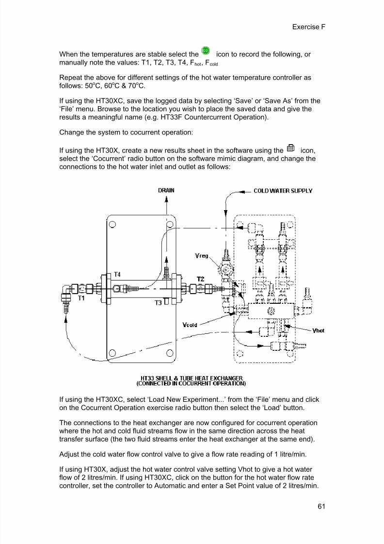
7/23/2019 HT33 Instruction Manual Issue 14
http://slidepdf.com/reader/full/ht33-instruction-manual-issue-14 65/70
Exercise F
When the temperatures are stable select the icon to record the following, ormanually note the values: T1, T2, T3, T4, F hot, Fcold
Repeat the above for different settings of the hot water temperature controller asfollows: 50oC, 60oC & 70oC.
If using the HT30XC, save the logged data by selecting ‘Save’ or ‘Save As’ from the‘File’ menu. Browse to the location you wish to place the saved data and give theresults a meaningful name (e.g. HT33F Countercurrent Operation).
Change the system to cocurrent operation:
If using the HT30X, create a new results sheet in the software using the icon,select the ‘Cocurrent’ radio button on the software mimic diagram, and change theconnections to the hot water inlet and outlet as follows:
If using the HT30XC, select ‘Load New Experiment...’ from the ‘File’ menu and clickon the Cocurrent Operation exercise radio button then select the ‘Load’ button.
The connections to the heat exchanger are now configured for cocurrent operationwhere the hot and cold fluid streams flow in the same direction across the heattransfer surface (the two fluid streams enter the heat exchanger at the same end).
Adjust the cold water flow control valve to give a flow rate reading of 1 litre/min.
If using HT30X, adjust the hot water control valve setting Vhot to give a hot water
flow of 2 litres/min. If using HT30XC, click on the button for the hot water flow ratecontroller, set the controller to Automatic and enter a Set Point value of 2 litres/min.
61

7/23/2019 HT33 Instruction Manual Issue 14
http://slidepdf.com/reader/full/ht33-instruction-manual-issue-14 66/70
Armfield Instruction Manual
Set the temperature controller to 40°C.
Allow the temperatures to stabilise (monitor the temperatures using the sensordisplay on the software screen or control console).
When the temperatures are stable, select the icon to record the following orrecord the values manually: T1, T2, T3, T4, F hot, Fcold
Repeat the above for different settings of the hot water temperature controller asfollows: 50oC, 60oC & 70oC.
If a supply of cold water is available at variable temperature the exercise can berepeated for different cold water inlet temperatures. Remember to create a newresults sheet for each set of results, and to configure the hardware and/or softwarefor countercurrent or cocurrent operation as required. The software will not correctlycalculate the derived values if it has not been properly configured.
If using the HT30X or HT30XC software, save the logged data by selecting ‘Save’ or‘Save As’ from the ‘File’ menu. Browse to the location you wish to place the saveddata and give the results a meaningful name (e.g. HT33F Cocurrent Operation).
Results and Calculations
Technical data:
Inner tube inside diameter d i = 0.00515 (m)
Inner tube outside diameter do = 0.00635 (m)
Heat transmission length L = 1.008 (total) (m)
The software records all sensor outputs and also calculates several derived figures,and presents the recorded data in tabular form. The following columns are relevant tothis exercise, and are suggested as suitable column headings if recording datamanually:
Hot fluid volume flowrate qvhot (m3/s)Multiply Fhot (litres/min) by1.667x10-5
Hot fluid inlet temperature T1 (°C)
Hot fluid outlet temperature T2 (°C)
Cold fluid volume flowrate qvcold (m3/s)Multiply Fcold (litres/min) by1.667x10-5
Cold fluid inlet temperaturecountercurrent flow
T3 (°C)
Cold fluid outlet temperaturecountercurrent flow
T4 (°C)
You should also estimate the experimental errors for these measurements.
62
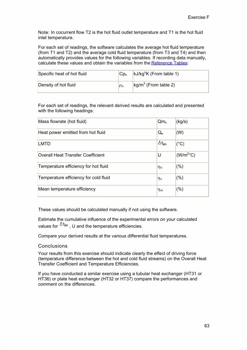
7/23/2019 HT33 Instruction Manual Issue 14
http://slidepdf.com/reader/full/ht33-instruction-manual-issue-14 67/70
Exercise F
Note: In cocurrent flow T2 is the hot fluid outlet temperature and T1 is the hot fluidinlet temperature.
For each set of readings, the software calculates the average hot fluid temperature(from T1 and T2) and the average cold fluid temperature (from T3 and T4) and thenautomatically provides values for the following variables. If recording data manually,calculate these values and obtain the variables from the Reference Tables:
Specific heat of hot fluid Cph kJ/kgoK (From table 1)
Density of hot fluid h kg/m3 (From table 2)
For each set of readings, the relevant derived results are calculated and presentedwith the following headings:
Mass flowrate (hot fluid) Qmh (kg/s)
Heat power emitted from hot fluid Qe (W)
LMTD (°C)
Overall Heat Transfer Coefficient U (W/m2°C)
Temperature efficiency for hot fluid h (%)
Temperature efficiency for cold fluid c (%)
Mean temperature efficiency m (%)
These values should be calculated manually if not using the software.
Estimate the cumulative influence of the experimental errors on your calculated
values for , U and the temperature efficiencies.
Compare your derived results at the various differential fluid temperatures.
Conclusions
Your results from this exercise should indicate clearly the effect of driving force(temperature difference between the hot and cold fluid streams) on the Overall HeatTransfer Coefficient and Temperature Efficiencies.
If you have conducted a similar exercise using a tubular heat exchanger (HT31 orHT36) or plate heat exchanger (HT32 or HT37) compare the performances andcomment on the differences.
63

7/23/2019 HT33 Instruction Manual Issue 14
http://slidepdf.com/reader/full/ht33-instruction-manual-issue-14 68/70
64
Exercise G: Project Work
To investigate heat loss from the Shell and Tube Heat Exchanger
Practical Teaching Exercises A to F are performed with hot water flowing through theinner tubes and cold water flowing through the outer annulus. This arrangement
minimises the loss of heat from the heat exchanger because the temperaturedifference between the cold water stream and the ambient air is relatively small. (Ifthe ambient air temperature is higher than the average temperature of the cold waterstream then a small gain in heat can occur.)
An investigation of heat loss from the heat exchanger when the hot water flowsthorough the outer annulus would provide a suitable project for students who havecompleted the previous training exercises. The quick release fittings between theheat exchanger and the service unit will allow the hot and cold fluid streams to beinterchanged.
By comparing the heat power emitted from the hot water with the heat power
absorbed by the cold water, the heat loss form the exchanger to the surroundingscan be determined. Details of the necessary measurements and calculations aregiven in practical Teaching Exercise B.
Note: As the outer annulus of the heat exchanger is manufactured using clear acrylictube, the hot water flowing through the outer annulus should be limited to 65°C tominimise softening of the tube. Similarly, the heat exchanger should not be operatedwith hot water in the outer annulus for long periods of time.
To investigate reduction in heat transfer coefficient due to fouling of theheat transfer surfaces
The effect of fouling of the heat transfer surfaced can provide an interesting projectfor students who have completed the previous Teaching Exercises.
The construction of the heat exchanger using ‘O’ ring seals allows the inner tubes tobe easily removed and replaced with alternative tubes inside which the surface hasbeen pre-fouled.
Seven metal tubes 6.35mm (¼“) outside diameter, 0.6mm wall thickness and 166mmlong (not supplied) should be provided for the student to foul by coating the insidediameter with a suitable insulating layer.
Note: The action of pushing the metal tube through an ‘O’ ring prevents theapplication of fouling to the outer surface of the metal tube.
If alternative tubing is not available then the existing tubes can be fouled but it will benecessary to remove the fouling before using the heat exchanger for normalmeasurements.
To remove the inner metal tubes from the heat exchanger, disconnect the quickrelease fittings from the exchanger, then carefully remove the headers (end plates)from the exchanger assembly (sealed using ‘O’ ring seals) before pushing out theindividual metal tubes. If the tubes do not move easily a small amount of wettingagent should be poured into the ‘O’ ring housings at the end of each tube to preventdamage to the ‘O’ ring seals.
Before re-inserting the metal tubes, or installing alternative tubes with fouling on theinner surface, lubricate the ‘O’ ring seals with a small amount of wetting agent.

7/23/2019 HT33 Instruction Manual Issue 14
http://slidepdf.com/reader/full/ht33-instruction-manual-issue-14 69/70
Exercise G
Designing an alternative heat exchanger
An interesting project for students who have completed the previous trainingexercises is to build and test a heat exchanger of their own design. Provided that thealternative heat exchanger is constructed with inlet and outlet connections to suit thequick release fittings on the HT33 Shell and Tube Heat Exchanger, then the fittings
used on the HT33 may be transferred directly, complete with the temperaturesensors fitted. The alternative heat exchanger can then be connected directly to theHT30X/HT30XC service unit for evaluation.
The inlet and outlet tubes should be 9.5mm (3/8”) outside diameter to allow directconnection to the fitting supplied with the HT33 Shell and Tube Heat Exchanger. Ifusing the temperature sensors only from the HT33 then the tappings for thetemperature sensors should be 9.5mm (3/8”) inside diameter.
Practical Teaching Exercises A to F may be applied to the students’ own design ofheat exchanger as appropriate.
Typical projects might include:
A Shell and Tube Heat Exchanger constructed with different internaldimensions, e.g. different tube diameter/shell diameter.
A Shell and Tube Heat Exchanger constructed using different materials, e.g.tube bundle manufactured from copper.
A Shell and Tube Heat Exchanger with different tube bundle geometry(spacing of tubes or different pattern/number of tubes).
A Shell and Tube Heat Exchanger with the tubes arranged for multi-pass
operation (ends of tube bundle connected to allow hot fluid to flow through thetubes in series instead of parallel).
65

7/23/2019 HT33 Instruction Manual Issue 14
http://slidepdf.com/reader/full/ht33-instruction-manual-issue-14 70/70
Contact Details for Further Information
Main Office: Armf ield Limited
Bridge HouseWest StreetRingwoodHampshireEngland BH24 1DY
Tel: +44 (0)1425 478781Fax: +44 (0)1425 470916Email: [email protected]
[email protected]: http://www.armfield.co.uk
US Office: Armfield Inc.
436 West Commodore Blvd (#2)Jackson, NJ 08527
Tel: (732) 928 3332Fax: (732) 928 3542Email: [email protected]