htgr brayton cycle - mit energy...
TRANSCRIPT

HTGR Brayton CycleTechnology and Operations
Xing L. Yan
HTGR Hydrogen and Heat Application Research CenterJapan Atomic Energy Agency (JAEA)
MIT Workshop on New Cross-cutting Technologies for Nuclear Power
Plants, Cambridge, USA, January 30-31, 2017
Contents
1
Highlighted with JAEA’s GTHTR300 technology
1. Power Conversion Cycle Parameters
2. Cost
3. Operations
4. Readiness and Qualification
950oC
6.23 MPa
688oC
3,32 MPa
135oC
6.42 MPa
28oC
3.21 MPa
163oC
3.24 MPa
666oC
6.37 MPa
302 MWe
50.4%
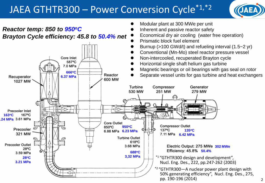
*1 “GTHTR300 design and development”, Nucl. Eng. Des., 222, pp.247-262 (2003)
JAEA GTHTR300 – Power Conversion Cycle*1,*2
2
Modular plant at 300 MWe per unit
Inherent and passive reactor safety
Economical dry air cooling (water free operation)
Prismatic block fuel element
Burnup (>100 GWd/t) and refueling interval (1.5~2 yr)
Conventional (Mn-Mo) steel reactor pressure vessel
Non-intercooled, recuperated Brayton cycle
Horizontal single shaft helium gas turbine
Magnetic bearings or oil bearings with gas seal on rotor
Separate vessel units for gas turbine and heat exchangers
Reactor temp: 850 to 950oC
Brayton Cycle efficiency: 45.8 to 50.4% net
*2 “GTHTR300—A nuclear power plant design with50% generating efficiency”, Nucl. Eng. Des., 275, pp. 190-196 (2014)
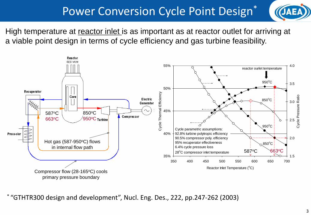
Power Conversion Cycle Point Design*
3
35%
40%
45%
50%
55%
350 400 450 500 550 600 650 700
Reactor Inlet Temperature (oC)
Cycle
Th
erm
al E
ffic
ien
cy
1.5
2.0
2.5
3.0
3.5
4.0
Cycle
Pre
ssu
re R
atio
950oC
850oC
950oC
850oC
reactor ourlet temperature
Cycle parametric assumptions:
92.8% turbine polytropic efficiency
90.5% compressor poly. efficiency
95% recuperator effectiveness
6.4% cycle pressure loss
28oC compressor inlet temperature
587oC
663oC
850oC
950oC
Hot gas (587-950oC) flows
in internal flow path
Compressor flow (28-165oC) cools
primary pressure boundary
587oC 663oC
* “GTHTR300 design and development”, Nucl. Eng. Des., 222, pp.247-262 (2003)
High temperature at reactor inlet is as important as at reactor outlet for arriving at
a viable point design in terms of cycle efficiency and gas turbine feasibility.
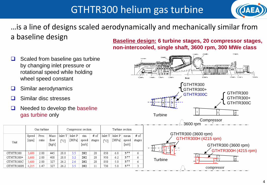
GTHTR300 helium gas turbine
4
3600 rpm compressor
20
6 4 1
11 1
GTHTR300
GTHTR300+
GTHTR300C
turbine
GTHTR300
GTHTR300C
GTHTR300+
turbine
compressor
GTHTR300H (4215 rpm)
GTHTR300 (3600 rpm)
GTHTR300 (3600 rpm)
1
1 4
6
20 11 1
11
1 3 GTHTR300H (4215 rpm)
Baseline design: 6 turbine stages, 20 compressor stages,
non-intercooled, single shaft, 3600 rpm, 300 MWe class
Scaled from baseline gas turbine
by changing inlet pressure or
rotational speed while holding
wheel speed constant
Similar aerodynamics
Similar disc stresses
Needed to develop the baseline
gas turbine only Turbine
Turbine
3600 rpmCompressor
GTHTR300
GTHTR300+
GTHTR300C GTHTR300
GTHTR300+
GTHTR300C
GTHTR300 (3600 rpm)GTHTR300H (4215 rpm)
GTHTR300H (4215 rpm)
GTHTR300 (3600 rpm)
…is a line of designs scaled aerodynamically and mechanically similar from a baseline design

GTHTR300 typical applications
5
Hydrogen Cogeneration
Reactor : 600 MWtElectricity: ~300 MWeHydrogen : ~120 t/d
MSF desalinationcogeneration
Reactor: 600 MWtElectricity: 280 MWe
Potable water: 55,000 m3/d
Reactor thermal: 600 MWt
Net electricity: 300 MWe
Generation efficiency: 50%
Reactor power (max. output) 600 MWtReactor temperature 850-950oCRefueling interval/period 1.5-2 yrs/30 daysPlant load factor 90%Reactor coolant pressure 7 MPaTypical products (max. output)
• Hydrogen (thermochemical method) 120 t/d• Electric power (50% net efficiency) 300 MWe• Desalination (cogenerated w/power) 55,000 m3/d• Steel (CO2 free steelmaking) 0.65 million t/yr
GTHTR300: Peak production parameters
Power Generation
Reactor
Reactor

GTHTR300 Cost Estimates
6
Construction Cost*1 (per reactor unit, 4 units/plant, NOAK)
Reactor ¥17,080M
Power Conversion ¥14,011M
Auxiliary ¥ 6,723M
Electric, Instrumentation & Control ¥ 5,780M
Buildings ¥11,071M
Total ¥54,665M (~US$2,000/kWe)
Electricity Cost (3% discount rate, 40 years operation, 80% availability)
Year estimated -> 2006*1 2014
Capital *2 ¥1.6/kWh ¥2.0/kWh
Operation & Maintenance ¥1.1/kWh ¥1.9/kWh
Fuel *3 ¥1.4/kWh ¥1.4/kWh
Total ¥4.1/kWh ¥5.3/kWh
*1 Economical Evaluation on Gas Turbine High Temperature Reactor 300
(GTHTR300) Vol. 5(2) p. 109-117 (2006)*2 Including decommissioning cost, *3 Including reprocessing cost
US$1≈J¥100

GTHTR300 Cost Estimates (details)
7
US$1≈J¥100Construction cost Capital cost (Yen/kWh)
Operating cost (Yen/kWh)
Power generation cost (Yen/kWh)
Fuel cost (Yen/kWh)

Operations – control system
8
1. Control rod
(reactor outlet
temperature)
2. Coolant
inventory
(load follow)
3. Flow bypass
(recuperator
temperature)
4. Flow bypass
(turbine overspeed)
Reactor Compressor Turbine Generator
Precooler Recupertor

Operations – simulation results
9
Full ↔ Part load operation –
with inventory control Loss of load –
with turbine flow bypass control
0
20
40
60
80
100
120
0 5 10 15 20 25 30 35 40 45
時間 (時間)
出力 (%)
0
20
40
60
80
100
120
発電機出力
原子炉出力
0
1
2
3
4
5
6
7
8
0 5 10 15 20 25 30 35 40 45
時間 (時間)
圧力 (MPa)
0
1
2
3
4
5
6
7
8
タービン出口圧力
圧縮機出口圧力
Generator output
Reactor power
Turbine exit pressure
Compressor exit pressure
0
20
40
60
80
100
120
0 500 1000 1500 2000
時間 (秒)
出力 (%)
0
20
40
60
80
100
120
発電機出力
原子炉出力
0
20
40
60
80
100
120
0 500 1000 1500 2000
時間 (秒)
回転数 (%)
0
20
40
60
80
100
120
タービン・圧縮機回転数
Generator output
Reactor power
Gas turbine rotational speed

RPV
RPV
gas turbine generator
gas turbine
PCV – power conversion vessel
reactor
reactor
“greenhouse”
Maintenance area Spare unit
Generator
10
① Disconnect the PCV flange② separate the generator section③ Disconnect the gas turbine unit supports and flanges with remote arms④ Pull the gas turbine unit out of the PCV on rail into “greenhouse”⑤Move the gas turbine unit to maintenance area⑥ Restore the PCV with pre-refurbished (spare) unit in reversed orders ⑤ -> ①
Gas turbine maintenance sequence (service period: 22 days)
Operations – Maintenance access
制御建家原子炉建家
GTHTR300 reactor building Gas turbine maintenance sequence

11
7th day
Parallel off the grid Parallel on the grid
55 days
⑧
⑦
⑥
⑤
④
③
②
①1 day
16 days
6 days
6 days
10 days
7.5 days
2 days
6.5 days
① System cooling② Core cooling (decay heat)③ Separate generator section ④ Remove gas turbine⑤ Restore PCV⑥ ISI to SCS⑦ Pre-startup test⑧ Startup
ISI to pressure boudaries
Tests ofCRD
Refueling
Maintenance of cooling water system
Maintenance ofgenerator
Critical path
7th day
33 days
Parallel off the grid Parallel on the grid
⑦
⑥
⑤
④
③
②
①
① System cooling② Core cooling (decay heat)③ Refueling④ Restore CR⑤ Pre-startup test⑥ Tests of CRD⑦ Startup
Maintenance of CR
1 day
17 days
23 days1.5 days
6 days
5.5 days
2 days
ISI to pressure boudaries
Maintenance of SCS
Maintenance of cooling water system
Critical path
Critical pathCritical path
1st cycle: refuel 2nd cycle: refuel+gas turbine maintenance cycle
(then repeat 1st cycle)
GTHTR300 shutdown maintenance cycles Refuel service interval: 2 years Gas turbine service interval: 4 years
Downtime impact on plant availability: 6%
Operations – Maintenance cycles
Critical path

Readiness & qualification – technologies developed
HTTR
(1) HTGR technology
Technology of fuel, graphite, superalloy and experience of operation, and maintenance.
Post-F1 safety evaluation by NRA is underway.
(2) GT and hydrogen technology
(3) Commerical HTGR design
GTHTR300
GTHTR300 for electricity generation and desalination
GTHTR300 for cogeneration and nuclear/renewable energy synergy system
HTGR with Thorium fuel
Clean Burn HTGR for surplus plutonium burning
Establishment of safety design philosophy
R&D of gas turbine technologies such as helium compressor, recuperator, magnetic bearing, gas seal, maintenance, etc.
In 2016, 31 hours of continousautomated hydrogen production with a rate of 20NL/h was successfully achieved.
30 MWt and 950oC prismatic core advanced test reactor (Operation started in 1998)
He compressor
hydrogen facility
(4) System demonstration test
Connection of helium gas turbine power generation system and then hydrogen cogeneration system to the HTTR.
Basic design for the HTTR-GT/H2 test is now underway.
12
HTTR-GT/H2

13
11 Design method calibrated by
1/3 scale helium compressor
test
Full scale compressor
adiabatic efficiency: 90.3%
(polytropic efficiency 91.5%)
Helium compressor technology*
Helium compressor test rig
Helium compressor
*Aerodynamic design, model test and CFD analysis for multistage axial helium compressor, Journal of Turbomachinery,130 / 031018, pp.1-12 (2008)
Traversed flow path probes

14
• 1/3 scale, MB-rotor (5 tons)
test rig constructed
• Test operated above first
bending critical speed
• Control system tested
0.1
1.0
10.0
0.1 1.0 10.0
No
rmar
ize
d c
riti
cal s
pe
ed
[ω/ω
3rd
]
Normarized bearing stiffness [K/Kdesign]
1st
2nd
3rd
4th
5th
Test rotor map -------Full rotor map
3600 rpm
rated operating point
Validated runs
33
Test data
Helium rotor bearing and gas seal technology
Magnetic bearing
Gas seal (to allow use of oil bearing)
• Industrial design evaluated
• Leak expected to be minimum
(<< HTTR safety license
requirement)
• Verification test planned

Readiness and qualification - technical roadmap
15
GTHTR300 basic design and component development
(2001- )Collaborative work with MHI
World’s first successful operation of axial He compressor, He compressor design method validated
Full-size turbine
hot-function test
850oC
Plant uprate
Present
Conceptual design for GTHTR300 power generation system
(1998-2001)
Technology transfer to private company
HTTR-GT/H2 construction and operation (2015-2024)
GTHTR300Commercial lead plant
(2025)
•850oC reactor outlet•Full size reactor build to allow uprate to 300 MWe without designmodification
•Turbine disc/casing clearance confirmation
Single turbine disc
•Basic design, safety design, and cost estimation•Development of high-efficiency He
compressor, compact heat exchanger, etc.•Turbine blade alloy development

16
Reference materials
17
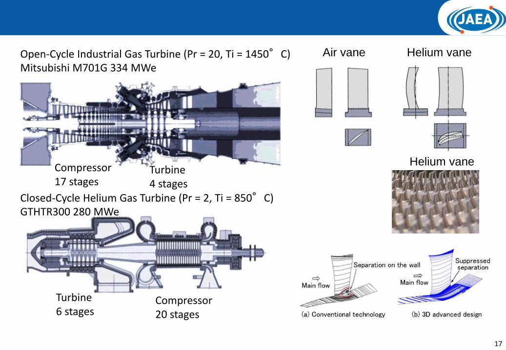
Open-Cycle Industrial Gas Turbine (Pr = 20, Ti = 1450°C)Mitsubishi M701G 334 MWe
Closed-Cycle Helium Gas Turbine (Pr = 2, Ti = 850°C)GTHTR300 280 MWe
Compressor17 stages
Compressor20 stages
Turbine6 stages
Turbine4 stages
Air vane Helium vane
Helium vane

Development status (2/2)- Balance of plant technologies developed in Japan
950℃5MPa
850℃
600℃
Reactor
(600MWt)
Gas-turbine
He circulator
O2
H2
H2O
900oC helium
isolation valve
IHXPrecooler
Recuperator
Hydrogen
production plant
900oC5.15 MPa
To Grid
200 MWe
IHX
cm
1.2mm
11
Production-
scale fuel
fabrication
Highly
effective heat
exchanger950oC He/He
heat
exchanger
Gas turbine magnetic bearing
Gas turbine helium compressor
IS-process test
18