hts bulk magnetic application in flywheel energy …atz-gmbh.com/maglev14_rio_de_janeiro.pdf · hts...
TRANSCRIPT

1
HTS Bulk Magnetic Application in Flywheel Energy
Storage Systems FESS and MAGLEV
Transportation
Frank N. Werfel Uta Floegel- Delor, Rolf Rothfeld, Thomas Riedel, Dieter
Wippich, Peter Schirrmeister, Rene Koenig Adelwitz Technologiezentrum GmbH (ATZ), Torgau, Germany;
[email protected]; [email protected]
Abstract
With High Temperature Superconducting (HTS) magnet technology a great potential of
application in superconducting magnetic bearing (SMB) and linear magnetic levitation
(MAGLEV) technology becomes attractive. Besides the superconductor each application sets
specific technical requirements. We present our study and work contributions on improvements of
rotational and linear magnetic bearings to stabilize heavy flywheel fiber rotors and mobile vehicles
in three different larger MAGLEV train concepts. We discuss the design and fabrication of an
Flywheel energy storage system FESS with an 1-ton load SMB on top. The SMB force density
approaches 10 – 15 N/cm² in axial direction at 2-3 millimeter magnet gap interaction for journal-
type bearings and a density of 5 - 7 N/cm² for linear MAGLEV vehicles at centimeter-sized gap
distances. We describe the attempts to increase the force beyond the present 10 kN bearing load
performance and to control sensitive bearing issues as damping, cooling and rotor dynamics.
Magnetic levitation trains tested on linear and circular guideways from 40 to 150 m length attract
great interest for future extension of mobility in urban and local transportation. Compact and
robust vacuum cryostat’s containing YBCO bulk HTS with LN2 cooling enable improved mobility
and operation of larger MAGLEV trains for transporting people and goods. Three different larger
MAGLEV train demonstrator concepts using YBCO bulk cryostats in Brazil, China and Germany
are compared in their present status.
1 Introduction
The continuous development of high- Tc material, both in bulks and wires improves the possible
application that is in most cases a magnetic one. Magnetic levitation is a fascinating effect demonstrated
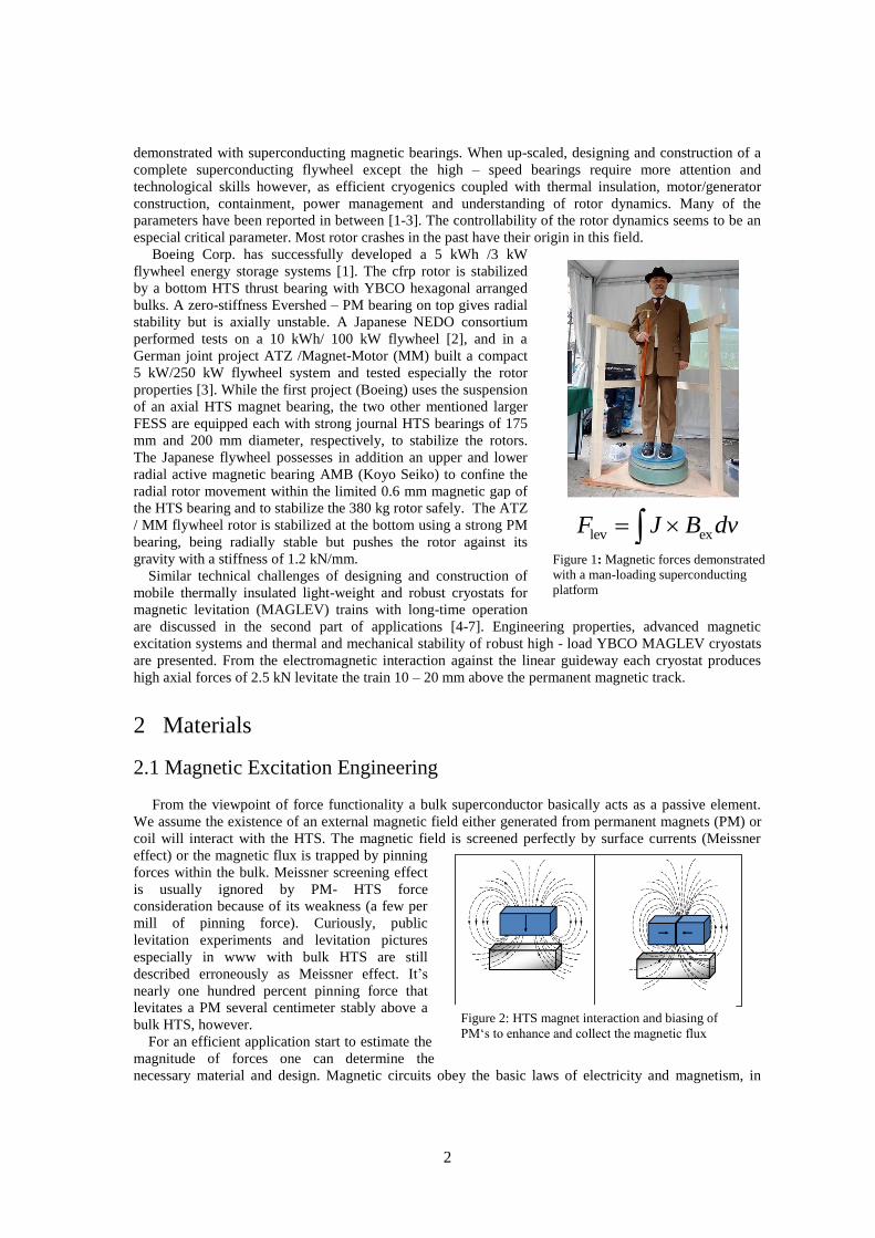
by the man – loading magnetic levitation platform in Fig. 1. Correspondingly, technical magnetic bearings
use the interaction between magnetic fields and bulk superconductors governed by the relations of
magneto-motoric forces according to Maxwell and Faraday. The availability of these bearings opens new
possibilities for their applications. SMB have specific properties that differentiate them from mechanical
bearings. The principle advantages are related to the absence of any physical contact with a number of
benefits as no lubrication and abrasion, ideal for clean- room application and the ability to operate under
complicate conditions like vacuum, cold, steam, heat and aggressive chemical environment. The greatest
obvious practical advantage is the exclusion of any solid friction allowing a high-speed, low– noise and
smart operation. The small loss that is still present being caused by the not perfect homogeneously
magnetized rotor or magnetic guideway configurations.
The use of extremely low-loss high-temperature superconducting (HTS) bearings is deemed necessary
to meet the long idle time requirements of flywheel energy storage systems (FESS). High specific stored
energy in a level of 10 kWh will require corresponding rotational speeds of perhaps 10000 rpm and rotor
weights up to several hundred kilograms. At the beginning of the HTS era flywheels have been
2
Figure 2: HTS magnet interaction and biasing of
PM‘s to enhance and collect the magnetic flux
lev exF J B dv
Figure 1: Magnetic forces demonstrated
with a man-loading superconducting
platform
demonstrated with superconducting magnetic bearings. When up-scaled, designing and construction of a
complete superconducting flywheel except the high – speed bearings require more attention and
technological skills however, as efficient cryogenics coupled with thermal insulation, motor/generator
construction, containment, power management and understanding of rotor dynamics. Many of the
parameters have been reported in between [1-3]. The controllability of the rotor dynamics seems to be an
especial critical parameter. Most rotor crashes in the past have their origin in this field.
Boeing Corp. has successfully developed a 5 kWh /3 kW
flywheel energy storage systems [1]. The cfrp rotor is stabilized
by a bottom HTS thrust bearing with YBCO hexagonal arranged
bulks. A zero-stiffness Evershed – PM bearing on top gives radial
stability but is axially unstable. A Japanese NEDO consortium
performed tests on a 10 kWh/ 100 kW flywheel [2], and in a
German joint project ATZ /Magnet-Motor (MM) built a compact
5 kW/250 kW flywheel system and tested especially the rotor
properties [3]. While the first project (Boeing) uses the suspension
of an axial HTS magnet bearing, the two other mentioned larger
FESS are equipped each with strong journal HTS bearings of 175
mm and 200 mm diameter, respectively, to stabilize the rotors.
The Japanese flywheel possesses in addition an upper and lower
radial active magnetic bearing AMB (Koyo Seiko) to confine the
radial rotor movement within the limited 0.6 mm magnetic gap of
the HTS bearing and to stabilize the 380 kg rotor safely. The ATZ
/ MM flywheel rotor is stabilized at the bottom using a strong PM
bearing, being radially stable but pushes the rotor against its
gravity with a stiffness of 1.2 kN/mm.
Similar technical challenges of designing and construction of
mobile thermally insulated light-weight and robust cryostats for
magnetic levitation (MAGLEV) trains with long-time operation
are discussed in the second part of applications [4-7]. Engineering properties, advanced magnetic
excitation systems and thermal and mechanical stability of robust high - load YBCO MAGLEV cryostats
are presented. From the electromagnetic interaction against the linear guideway each cryostat produces
high axial forces of 2.5 kN levitate the train 10 – 20 mm above the permanent magnetic track.
2 Materials
2.1 Magnetic Excitation Engineering
From the viewpoint of force functionality a bulk superconductor basically acts as a passive element.
We assume the existence of an external magnetic field either generated from permanent magnets (PM) or
coil will interact with the HTS. The magnetic field is screened perfectly by surface currents (Meissner
effect) or the magnetic flux is trapped by pinning
forces within the bulk. Meissner screening effect
is usually ignored by PM- HTS force
consideration because of its weakness (a few per
mill of pinning force). Curiously, public
levitation experiments and levitation pictures
especially in www with bulk HTS are still
described erroneously as Meissner effect. It’s
nearly one hundred percent pinning force that
levitates a PM several centimeter stably above a
bulk HTS, however.
For an efficient application start to estimate the
magnitude of forces one can determine the
necessary material and design. Magnetic circuits obey the basic laws of electricity and magnetism, in

3
Figure 4: FEM 2D calculation of generated flux of
different PM geometry; left D x h = 30 x 35, right
50 x 40.; distance 10 mm
0,0 0,5 1,0 1,5 2,0
0,01
0,1
1Mirror principle FEM (2D)
relative force density
DCB
= 0.5 x d
= 1 x d
h = 2 x d
g
d
mirror
HTS
PM
D
C
B
pd
ia / µ
0H
c
2/2
gap / diameter
Figure 3: FEM 2D calculation of the expected magnetic
pressure relative to the magnet performance based on the
mirror image concept
special the rules for conversation of magneto-motoric force. The performance PMs in Fig. 2 depend on the
energy product (BH)max with an operating point at half of the coercitivity force HPM ~ Hc/2 and a
magnetic flux density about half of the remanence force BPM ~ Br/2. To achieve higher magnetic forces
and larger magnetic flux density excitation a larger volume and mass input of the magnet material is
required. Parallel, magnetic engineering or sometimes called magnetic biasing can generate higher flux
densities and allows a motion of the vector of magnetization as it shown in Fig. 2. Thereby either the
magnets are pressed repulsively together or an iron sheet is positioned between the magnets to collect and
turn the flux.
In a first try of any levitation system the so-called mirror image concept is useful. It can give the
relation between the expected force density as a function of the magnet dimension and gap distance. The
calculation in Fig. 3 assumes an ideal diamagnetic superconductor response to an external magnetic
excitation. The magnetic interaction is thereby considered a one-to-one reaction. In this model both the
field magnitude of the response as well as regarding the position of the diamagnetic image follow
perfectly the origin. In Figure 3 the
distance force density FEM calculation of
permanent magnets in a principle 2D
mirror image is shown. The distance is a
simple ratio of the diameter of the PM
giving three curve parameters with
increased PM height ranging from half,
equal and double the distance to the
superconductor. The results on the
ordinate are given as pressure related
magnet performance Pdia/(µ0Hc2/2). Curves
and calculation give a first approach about
the expected force density for given PM
parameters.
For HTS bulk interaction two basic
magnetic sources are becoming practical,
permanent magnets and magnetic coils.
Practically easy to realize is the interaction
with PMs because no current supply
becomes necessary relative to coil
excitation. However, having a magnet and a superconductor wouldn’t automatically give a good magnetic
configuration or bearing. PMs need often configured and combined in opposite directions and generate
then a substantial flux enhancement as it is shown in Figure 2. Dependent on the distance to the HTS an
iron flux collector between the magnets improves the flux confinement and orientation. Further
optimization is possible by a Halbach configuration whereby the iron as flux collector is replaced by a PM
driving the total generated magnetic flux to one side of
the PM assembly. In Fig. 4 2D FEM calculation
compares two PMs with D x h to be 30 x 35 on left and
50 x 40, respectively. The field line distributions and
the determined integral flux at 10 mm distance
demonstrate the improvement. A double PM cross
section (right) increases the integral flux density by
about 25 % only, however.
Our technical experience collected over years with
PM rings indicates some other critical issues. PM rings
under rotation posses a sensitive material specific
tensile strength equivalent to about 120 m/s rim speed.
To overcome this limitation, high-strength composite
banding structure winded around needs to be used to
protect the PM rings from cracking. The banding
structure pre-stresses the PM ring under compression so
that high tensile stress will not be developed during

4
Figure 5: Top seeded melt growth stategy of ReBCO
bulk superconductors
Figure 6: 30 mm YBCO single grain bulks grown in
batch strategy; typical Btrap ~0.8 – 1 T
bearing rotation. If the PM ring is larger than a diameter of 200 mm (D > 200 mm) the ring needs to be
assembled from corresponding segments with probable introduction of magnetic field inhomogeneity.
Practically, a careful balance and compromise in the design between attaining higher speed and
maintaining a low-loss bearing has to be considered in each case.
Magnetic coil application as an alternative to PMs is mentioned briefly in the flywheel section.
2.2 REBCO Bulk Superconductors
In the following we will review briefly large- scale HTS bulk production in an engineering level
serving the increased HTS bulk demand for magnetic applications. Top seeded melt growth (TSMG) is a
well understand melt texturing process studied and improved in the last decade in many HTS groups [8-
10]. In addition, Light Rare Earth (LRE=Sm, Gd, Nd)) materials are attracting the interest, partly by using
generic thin film seeds (Sm123, Nd123) and
processing in reduced and normal oxygen
atmosphere [11,12]. Especially GdBCO bulk
samples prepared by cold -seeding seem to have
higher Jc values at 77 K compared to YBCO. Bulk
YBCO and GdBCO with large domain size up to
150 mm diameter and high intra –domain critical
current density has been developed by Quench
Melt Growth (QMG) method under reduced
oxygen atmosphere by Nippon Steel Corporation.
REBCO single grain bulks with extreme
dimensions above 80 – 100 mm diameter require a
material-controlled peritectic temperature gradient
to prevent parasitic nucleation and unwanted grain
growth.
Fig. 5 displays typical top seeded melt growth
(TSMG) YBCO growing procedure applied by ATZ for single grain fabrication [3]. The melt texture
process follows a characteristic temperature route: heating up to about 1050 0C, 0.5 – 1 hour dwell time,
fast cooling to 10150
– 9900 C and re-crystallization with a ramp-down of 0.5 – 1 K/h to 940
0C, cooling
with 50 K/h or furnace cooling to room temperature. In last step oxygen annealing the samples at 5000 to
3500
C for 200 h is performed. With the top seeding technique displayed in Figure 5 high quality
superconducting magnetic material in blocks of circular or rectangular shapes up to 60 mm can be
fabricated. Larger samples or superconductor bulks with circular shape (rings, tubes, and segments) could
not be easily grown as single crystalline material. Therefore, the bulks must be mechanically machined
into the desired shape, than assembled to the component design, glued together and fine-machined up to
the precise shape.
Using seeding technique single crystal
superconducting bulks can be fabricated in large
batches (Figure 6). 30 mm bulk cylinders in Figure
6 exhibit peak values of the trapped field of about
0.8 - 1.0 T at 77 K. However, by assembling the
individual grains the resulting magnetic pressure of
the assembly is limited due to the existence of (non-
superconducting) joints between bulks. For larger
applications, the average magnetization determined
over the total assembly is more important than the
peak values.
To raise the material quality for larger magnetic
applications we fabricate large-sized high
performance melt textured bulks with multi-seed
domain structure to increase the average trapped

5
Fig. 3.1.1.11
Figure 8: Principle of magnetization and critical
current density in bulk superconductor [BEAN
model]
Figure 7: Multi – seeded YBCO in the dimension 67 x 34 x 14; ideal for MAGLEV
cryostats; geometrical and seed geometry (right)
field value. In Figure 7 high-Tc TSGM YBCO bulks of 3- seed multiple-grain structure are shown. The
multiple- seeded samples reduce the machining and assembling effort and the production costs of larger
superconducting magnetic stator planes, rings or tubes. Helpful is the addition of Ag2O which decreases
the formation temperature substantially (10 wt % Ag drops Tp by nearly 8°C) without influencing the
material composition. In general, the fabrication effort and time for large bulks is substantial causing high
material costs. In addition, under machining and cutting procedure the probability of damage of such large
samples is always evident. In most cases such large bulk samples carry an external bandage to achieve a
better mechanical stability. A careful post-growing treatment is recommended. ATZ’s fabrication strategy
is therefore the corresponding assembling of 2:1 sized rectangular YBCO bulks (66 mm x 33 x 14 mm) in
Fig. 7 allowing the fabrication of both larger magnetic journal bearing HTS stators as well as plane-like
areas of assembled and glued bulks e. g. for MAGLEV cryostats.
2.3 Application Relevant Properties of HTS Bulks
2.3.1 Critical Current Density
High Tc- superconductors are capable to trap magnetic fields permanently and are becoming to
superconducting magnets. The principle schematics about trapped flux density in a bulk superconductor
are shown in Fig. 8. The trapping performance is proportional to the critical current density Jc of the
material. Jc is the most important parameter of all superconductors. In the successfully applied BEAN
model one assumes a simplified model for the current distribution.
In the critical state model, the sum of the quantized
vortex currents is substituted by a macroscopic screening
current density that the sample is capable to carry. In this
way, the material can be assumed to have the magnetic
permeability of free space (μ0), and a macroscopic
screening current density Jc with a non-linear relation of
the induced electric field in the material. The BEAN
model considers that this macroscopic current density has
a constant value equal to Jc. Inside the superconductor
the electromagnetic properties can be represented by a
non-linear E–J relation.
Measurements of the critical current density are
performed inductively using corresponding
magnetometers. Thereby, the induced magnetic moment
loops were measured on small specimens cut from the
parent grains using a Superconducting Quantum Design
SQUID magnetometer.

6
0 1 2 3 4
0
1000
2000
3000
HTS
F
20 mm radial bearing, 1 mm gap
B --> versus bulk orientation
polycrystalline
single grain B||c
B||ab
+Fe B||c
+Fe B||ab
axia
l fo
rce
F (
mN
)
displacement (mm)
Figure 9: Measurement of the YBCO orientation relative to
magnetic flux direction together with polycrystalline YBCO
stator
The Jc value parallel to the sample c axis was calculated for these specimens using the following
equation derived from the BEAN model:
Jc = 20(∆M)/a(1 − a/3b),
whereby ∆M is the hysteresis in the volume magnetization, a and b are the cross-sectional dimensions of
the sample perpendicular to the applied field and a < b.
Following the Maxwell equations the internal magnetic flux density rotation determines the critical
current by
x B = µ0 Jc
In one dimension, the above equation is reduced to:
dBx / dx = 0 Jc y in rectangular coordinates,
dBz / dr = µ0 Jc
in cylindrical coordinates, respectively
The maximum trapped field flux density in the z direction Bz, max
of an infinite long cylindrical sample
with a diameter of 2R is given by the following relation:
Bz max
= µ0 Jc R
After this equation, the maximum trapped field depends on the critical current density Jc and the diameter
D = 2R of the superconducting domain. In practice, the value is reduced by geometrical and
demagnetization effects by about 20% relative to applied magnetic flux density Ba.
As an example, in case of a cylinder geometry one has to consider dB/dr = μ0Jc, integrated in the Bean
model gives B* = μ0 Jc R for the maximum trapped magnetic flux B*. Assuming a critical current Jc = 104
A/cm² and a grain diameter 2R = 40 mm, it gives a trapped field value B* = 1.2 Tesla.
After above equations a better bulk performance is given by increasing the critical current density Jc as
well as by the length scale over which the currents flow, i.e. the grain size. Both factors determine the
field trapping ability that is improved
in the last decade routinely to
maximum values of 1.2 T at 77 K for
YBCO.
A geometrical condition for
generating high currents and high
trapped field values is an optimum
geometry of the magnetic field
component which should be
orthogonal to the crystallographic a, b
plane of YBCO single grain bulk.
Figure 9 displays measurements of
different YBCO cylinders with an
orientation parallel and perpendicular
to the radial magnetic flux
distribution. Surprisingly, the axial
force seems to be less sensitive to the
crystal orientation of the YBCO stator
for displacement values up to 4 mm.
In contrast, the polycrystalline stator exhibits lower magnetic forces as expected.
Very recently the Cambridge group reported about a trapped field of 17.6 T between a pair of melts
processed GdBCO bulks reinforced with a shrink-fit steel bandage [13]. Using a simple Bean approach
the critical persistent current has to be 1.12 x10⁵ A/cm². At this field the Lorentz force J x B is increased to
about 80 MPa, a factor three higher than the maximum tensile strength of ReBCO bulk material. From the
maximum trapped field of 17.6 T a repulsive magnetic pressure of 12.3 GPa would appear when two such
magnetized samples are pressed together.
7
1 2 3 4 5 6 7 8 9 10 11 12 130
5
10
15
20
25
30
35
40
45
50YBCO, with Cu impregnation
YBCO, melt textured
Cra
ck s
tress (
kN
/cm
²)
Sample No
Figure 10: Copper impregnation the surface of
YBCO melt textured samples with beneficial
improvement of the mechanical properties.
A
T+dt
x+dxIq
T
x x
Figure 11: Coefficient of the heat transfer of
polycrystalline melt textured YBCO
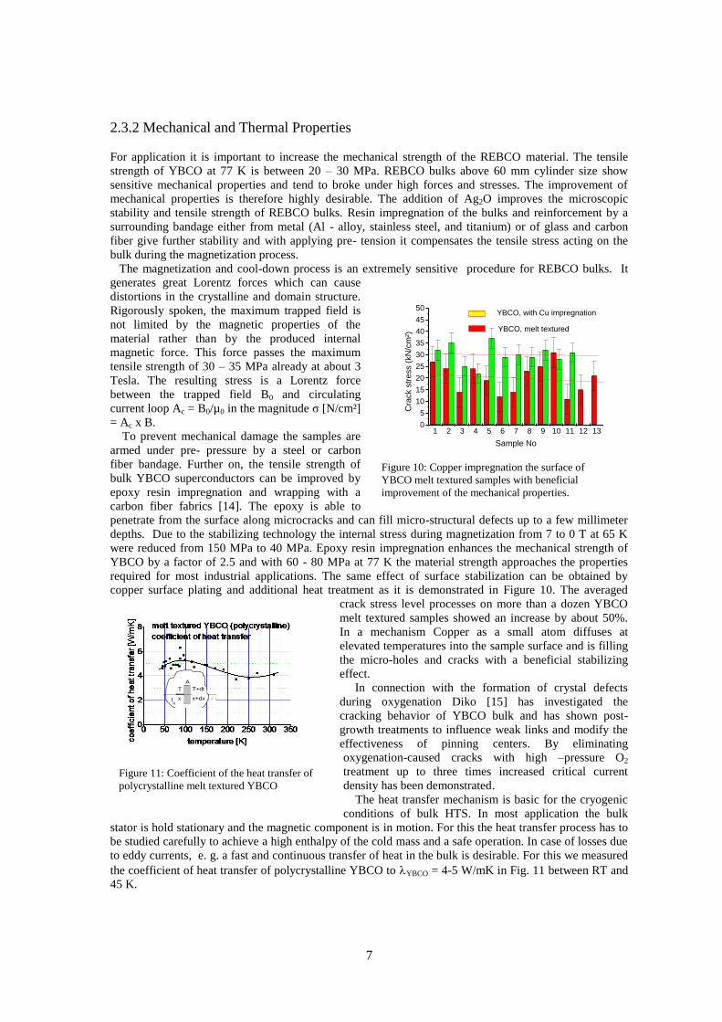
2.3.2 Mechanical and Thermal Properties
For application it is important to increase the mechanical strength of the REBCO material. The tensile
strength of YBCO at 77 K is between 20 – 30 MPa. REBCO bulks above 60 mm cylinder size show
sensitive mechanical properties and tend to broke under high forces and stresses. The improvement of
mechanical properties is therefore highly desirable. The addition of Ag2O improves the microscopic
stability and tensile strength of REBCO bulks. Resin impregnation of the bulks and reinforcement by a
surrounding bandage either from metal (Al - alloy, stainless steel, and titanium) or of glass and carbon
fiber give further stability and with applying pre- tension it compensates the tensile stress acting on the
bulk during the magnetization process.
The magnetization and cool-down process is an extremely sensitive procedure for REBCO bulks. It
generates great Lorentz forces which can cause
distortions in the crystalline and domain structure.
Rigorously spoken, the maximum trapped field is
not limited by the magnetic properties of the
material rather than by the produced internal
magnetic force. This force passes the maximum
tensile strength of 30 – 35 MPa already at about 3
Tesla. The resulting stress is a Lorentz force
between the trapped field B0 and circulating
current loop Ac = B0/µ0 in the magnitude σ [N/cm²]
= Ac x B.
To prevent mechanical damage the samples are
armed under pre- pressure by a steel or carbon
fiber bandage. Further on, the tensile strength of
bulk YBCO superconductors can be improved by
epoxy resin impregnation and wrapping with a
carbon fiber fabrics [14]. The epoxy is able to
penetrate from the surface along microcracks and can fill micro-structural defects up to a few millimeter
depths. Due to the stabilizing technology the internal stress during magnetization from 7 to 0 T at 65 K
were reduced from 150 MPa to 40 MPa. Epoxy resin impregnation enhances the mechanical strength of
YBCO by a factor of 2.5 and with 60 - 80 MPa at 77 K the material strength approaches the properties
required for most industrial applications. The same effect of surface stabilization can be obtained by
copper surface plating and additional heat treatment as it is demonstrated in Figure 10. The averaged
crack stress level processes on more than a dozen YBCO
melt textured samples showed an increase by about 50%.
In a mechanism Copper as a small atom diffuses at
elevated temperatures into the sample surface and is filling
the micro-holes and cracks with a beneficial stabilizing
effect.
In connection with the formation of crystal defects
during oxygenation Diko [15] has investigated the
cracking behavior of YBCO bulk and has shown post-
growth treatments to influence weak links and modify the
effectiveness of pinning centers. By eliminating
oxygenation-caused cracks with high –pressure O2
treatment up to three times increased critical current
density has been demonstrated.
The heat transfer mechanism is basic for the cryogenic
conditions of bulk HTS. In most application the bulk
stator is hold stationary and the magnetic component is in motion. For this the heat transfer process has to
be studied carefully to achieve a high enthalpy of the cold mass and a safe operation. In case of losses due
to eddy currents, e. g. a fast and continuous transfer of heat in the bulk is desirable. For this we measured
the coefficient of heat transfer of polycrystalline YBCO to YBCO = 4-5 W/mK in Fig. 11 between RT and
45 K.

8
Figure 12: Concept of flux trapping at
pinning centers
Figure 13: Trapped flux measurements at
single grain and multi-seed YBCO bulks
2.3.3 Doping Strategy
Besides the mechanical properties the material applicability is determined by pinning performance of
the magnetic flux in magnetic vortices (Shubnikov phase). Pinning is a process step displayed in Fig. 12
of microstructure engineering. The non-superconducting RE211 phase preferred in a nanoscale size
provides the basic pinning background. Compared to LTS the new HTS possess a relatively weak
intrinsic pinning. This observation has led to wide spectrum of doping concepts, ranging from columnar
defects generated by irradiation (in a thickness of a few mm), substitution of ions in the HTS atomic
structure, and specifically doping by addition of secondary phases.
A doping content of 0.3 wt% PtO2 and/or 0.6 wt% CeO2 is
effective to influence the microstructure to refine the Y211
particles. Because of increasing costs PtO2 doping is gradual
eliminated to refine RE2BCO5 precursor powder. It is
replaced by CeO2 doping which seems to have an equivalent
beneficial effect on the particle size.
The strong effect of refinement of second non-
superconducting phases RE211 or RE422 on the critical
current density has been shown in by Muralidhar [16].
Extremely fine 211 powders in nanometer scale are
produced by ball milling treatment technique. By adding
Gd211 of 70 nm size and 10 nm NbO3 particles on a mixed
NEG (Nd, Eu, Gd)–Ba-Cu-O matrix system Jc values of 925 kA/cm²@65 K and 640 kA/cm²@77 K could
be obtained. Even for 90 K the critical current density was in a level of 100 kA/cm².
2.4 HTS Bulk Characterization-Trapped
Magnetic Flux
Levitation force measurement for HTS bulk characterization
has a long tradition. The method was simply and easy to
perform but displays their limitation as the HTS bulk
material was becoming better electric and magnetic
properties. Today, the measurement of the trapped field
distribution after field cooled excitation seems a more
adequate and reliable parameter of the magnetic bulk
performance.
In Fig. 13 we demonstrate a magnetic flux density
distribution of a 46 mm YBCO bulk specimen. The
measured distribution is instructive in multiple regards.
Although the maximum excitation flux was 1.45 Tesla using
conventional Weiss magnet the measured trapped flux
density in the center of the sample is approximately 1.2 T at
0.5 mm distance. The gradient of the field distribution
changes from the center to boundary indicating different Jc
values. This behavior displays higher critical current density
values Jc near the bulk center and reduced critical super-
currents in the distance. Larger Jc at higher fields
correspond to the often observed peak effect at mixed
valence RE1-xRExBaCuO superconductors.
High resolution trapped field measurements can explain
the grain boundary behavior in multi-seed samples too. Fig.
13 in the center exhibits the flux distribution of a 3-seed
YBCO bulk after melt textured processing, preparation (flat
surface) and a surface scan. The as-grown sample with the

9
Figure 14: Concept of high gradient magnetic
bearing
SmBCO seeds on top show a non-vanishing trapped field distribution between the three peaks. The
scanning Hall results of multigrain bulks give evidence of components of the super-current across the
grain boundaries in the multi-seed bulk. While the intra-grain current determines the three individual
magnetic peaks, an additional inter-grain current can pass the GBs and contribute a substantial part to the
total trapped magnetic flux density integrated over the bulk. The latter is especially beneficial for large-
scale applications.
Larger bulk fabrication is demonstrated in Fig.13 bottom. YBCO blocks of the size 90mm x 60 mm 20
mm are tested for trapped flux motor application. The scanning Hall distribution displays 8 individual
crystals corresponding to the 8-seed structure. At an excitation field of 0.75 T the trapped flux peak values
scatter between 600 and 650 mT. While in the length direction the grain boundaries show a certain flux
overlap of 200 - 300 mT, in the perpendicular direction the neighboring 4-crystal rows indicate almost no
trapped flux overlapping distribution. The latter behavior gives some evidence that between the two 4-
crystal rows super-current is flowing rarely.
3 Flywheel with Superconducting Magnetic Bearing
For rotating application we favor the journal –type magnetic bearing interaction. Fig. 14 shows the
principal design and the rules for an optimized magnet excitation of a radial and axial high gradient HTS
bearing. The corresponding magnetic distribution of the B vectors (Br and Bz ) can be calculated. After
that the field decays with the exponential function
along the radius vector r and relative to the axial
distance of the magnet poles L (pole pitch). The
obtained by flux field gradient generated by the PM /
Fe configuration determines the radial force Fr and
stiffness dFr/dr. Along z direction a sin / cos function
covers the periodic field variation in axial direction
and determines the axial force and stiffness of the
magnetic bearing.
It has been shown that subdivision of the magnets in
a multi-pole arrangement with the pole pitch L in
Fig.14 increases the bearing stiffness provided the air
gap can be kept small. On the other hand, in
superconducting bearings force generation needs a
displacement. Small magnetic air gaps < 2 mm improve
the flux density in the gap but limit the possible
displacement of the rotor. For larger distances > 2 mm
the enhancement of the electromagnetic force due to Fe collectors is caused by the steeper flux gradient
generated by the Fe collectors. In addition, larger gaps are useful to prevent any dangerous rotor stator
contact in fast rotating machines, like flywheels or high-speed motors. The thermal insulation between the
cold HTS stator and the warm rotor (or vice versa) is becoming easier in assembling at larger gap
distances.
In the next chapter we compare the different FESS demonstrator concepts with superconducting
magnetic stabilization and the critical concepts. A self – stabilizing magnetic bearing is definitely a most fascinating and promising technology. Due to
its physical properties it needs no electronic control and operates completely passively. Basically, the HTS
bearing (SMB) is inherently fail-safe in contrast to active controlled bearing AMB after power loss. Using
liquid nitrogen as a cooling fluid the HTS superconductor is operated at fairly low temperature, far below
critical operation points and is therefore safe and reliable.
Because of the mechanical bearing friction a conventional flywheel loses about 2% of its stored energy
per hour lowering the round-trip efficiency for diurnal, load leveling to half of the daytime energy. A
magnetic bearing can reduce these losses by one order of magnitude. We therefore look first to the bearing
concepts. An operating temperature of liquid nitrogen (T=77 K) is considered as satisfactory and
sufficient far below the critical superconducting temperature Tc = 92 K, and therefore safe and reliable.
Better electromagnetic force density values up 13 N/cm² axial and 6.5 N/cm² and especially higher
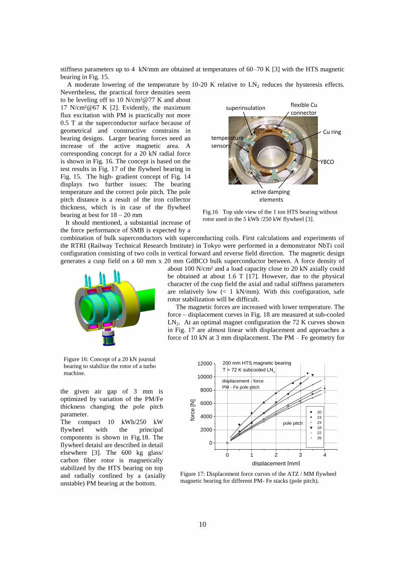
10
Figure 16: Concept of a 20 kN journal
bearing to stabilize the rotor of a turbo
machine.
Fig.16 Top side view of the 1 ton HTS bearing without
rotor used in the 5 kWh /250 kW flywheel [3].
0 1 2 3 4
0
2000
4000
6000
8000
10000
12000
displacement - force
PM - Fe pole pitch
200 mm HTS magnetic bearing
T = 72 K subcooled LN2
pole pitch
20
23
24
18
22
26
forc
e [N
]
displacement [mm]
Figure 17: Displacement force curves of the ATZ / MM flywheel
magnetic bearing for different PM- Fe stacks (pole pitch).
stiffness parameters up to 4 kN/mm are obtained at temperatures of 60–70 K [3] with the HTS magnetic
bearing in Fig. 15.
A moderate lowering of the temperature by 10-20 K relative to LN2 reduces the hysteresis effects.
Nevertheless, the practical force densities seem
to be leveling off to 10 N/cm²@77 K and about
17 N/cm²@67 K [2]. Evidently, the maximum
flux excitation with PM is practically not more
0.5 T at the superconductor surface because of
geometrical and constructive constrains in
bearing designs. Larger bearing forces need an
increase of the active magnetic area. A
corresponding concept for a 20 kN radial force
is shown in Fig. 16. The concept is based on the
test results in Fig. 17 of the flywheel bearing in
Fig. 15. The high- gradient concept of Fig. 14
displays two further issues: The bearing
temperature and the correct pole pitch. The pole
pitch distance is a result of the iron collector
thickness, which is in case of the flywheel
bearing at best for 18 – 20 mm
It should mentioned, a substantial increase of
the force performance of SMB is expected by a
combination of bulk superconductors with superconducting coils. First calculations and experiments of
the RTRI (Railway Technical Research Institute) in Tokyo were performed in a demonstrator NbTi coil
configuration consisting of two coils in vertical forward and reverse field direction. The magnetic design
generates a cusp field on a 60 mm x 20 mm GdBCO bulk superconductor between. A force density of
about 100 N/cm² and a load capacity close to 20 kN axially could
be obtained at about 1.6 T [17]. However, due to the physical
character of the cusp field the axial and radial stiffness parameters
are relatively low (< 1 kN/mm). With this configuration, safe
rotor stabilization will be difficult.
The magnetic forces are increased with lower temperature. The
force – displacement curves in Fig. 18 are measured at sub-cooled
LN2. At an optimal magnet configuration the 72 K curves shown
in Fig. 17 are almost linear with displacement and approaches a
force of 10 kN at 3 mm displacement. The PM – Fe geometry for
the given air gap of 3 mm is
optimized by variation of the PM/Fe
thickness changing the pole pitch
parameter.
The compact 10 kWh/250 kW
flywheel with the principal
components is shown in Fig.18. The
flywheel detaisl are described in detail
elsewhere [3]. The 600 kg glass/
carbon fiber rotor is magnetically
stabilized by the HTS bearing on top
and radially confined by a (axially
unstable) PM bearing at the bottom.
11
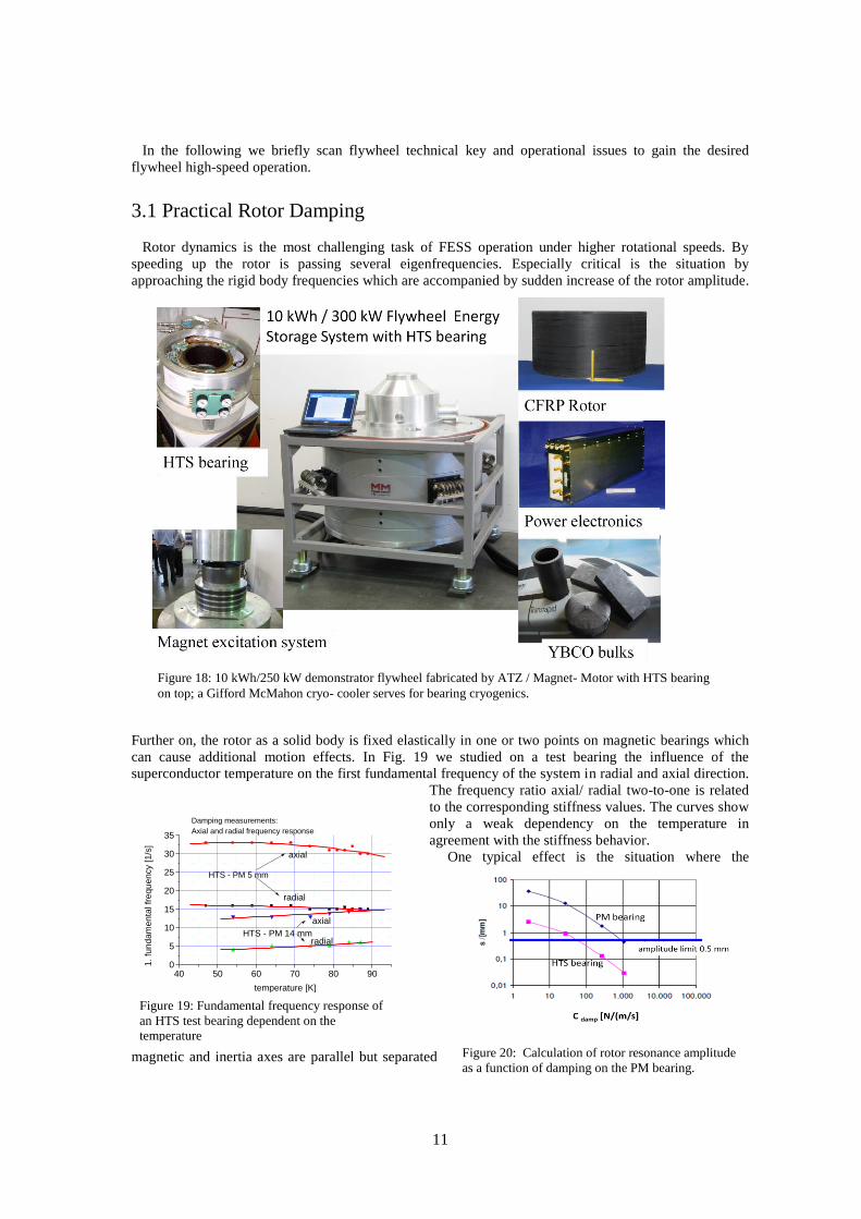
Figure 18: 10 kWh/250 kW demonstrator flywheel fabricated by ATZ / Magnet- Motor with HTS bearing
on top; a Gifford McMahon cryo- cooler serves for bearing cryogenics.
40 50 60 70 80 900
5
10
15
20
25
30
35
radial
axial
HTS - PM 14 mm
radial
axial
HTS - PM 5 mm
Damping measurements:
Axial and radial frequency response
1. fu
ndam
enta
l fr
equency [1/s
]
temperature [K]
Figure 19: Fundamental frequency response of
an HTS test bearing dependent on the
temperature
Figure 20: Calculation of rotor resonance amplitude
as a function of damping on the PM bearing.
In the following we briefly scan flywheel technical key and operational issues to gain the desired
flywheel high-speed operation.
3.1 Practical Rotor Damping
Rotor dynamics is the most challenging task of FESS operation under higher rotational speeds. By
speeding up the rotor is passing several eigenfrequencies. Especially critical is the situation by
approaching the rigid body frequencies which are accompanied by sudden increase of the rotor amplitude.
Further on, the rotor as a solid body is fixed elastically in one or two points on magnetic bearings which
can cause additional motion effects. In Fig. 19 we studied on a test bearing the influence of the
superconductor temperature on the first fundamental frequency of the system in radial and axial direction.
The frequency ratio axial/ radial two-to-one is related
to the corresponding stiffness values. The curves show
only a weak dependency on the temperature in
agreement with the stiffness behavior.
One typical effect is the situation where the
magnetic and inertia axes are parallel but separated

12
Figure 21: Flywheel rotor and the stress and shear
conditions
(2)
: strain : normal to tape
: shear : parallel to tape
- density of the material
h- axial thickness of the winding
by a distance. The structure of this resonance caused losses whereby rotor’s center of mass moves around
circles. If the geometric and magnetic axes of the rotor are not parallel, the dynamics of rotor is even more
complex.
We investigated the damping possibilities of our 5 kWh/250 kW flywheel with respect to HTS and PM
bearing. It followed a decision to provide our one-ton HTS bearing with an auxiliary damping system
shown in Fig. 15. The dampers are self-constructed and connect and stabilize the superconducting stator
with the housing. The four dampers have two functions: They operate by a pressurized viscous liquid and
fix the stator after cooling and thermal shrinking. Under rotation they damp the HTS bearing. With the
external HTS bearing dampers we calculated the effect of damping on the amplitude s of the PM bearing
in Fig. 20. The HTS bearing damping was constant cdamp(HTS) = 65 N/ (m/s). With a damping of 1000
N/(m/s) on the PM bearing the rotor amplitude is safely confined to an amplitude of 0.5 mm.
3.2 Carbon Fiber Rotor
Carbon or glass-fiber (cf, gf) rotor winding is a special engineering skill which belongs to the fiber
fabricating field, well known in modern airplanes for the wings or the body. In Fig. 21 we show a
photograph of the 600 kg gf-cf rotor of our 5 kWh /250 kW demonstrator flywheel [3]. The rotor is a
hollow cylinder and is made primarily of carbon fiber compound. To get the system compact, the
motor/generator (M/G) unit is integrated concentrically in the cylindrical rotor. Winding the rotor was
performed after calculations and tests about the maximum rim speed and the resultant centrifugal forces.
The centrifugal force (f) acting on a thin rim with the thickness t is obtained to be
In Fig. 21 the photo shows the carbon fiber (cf) rotor of the ATZ /MM FESS together with equilibrium
conditions of the stress and shear parameters under rotation with an angular speed . The condition of
equilibrium for the rotor stress distribution follows the equations. Under simplified conditions (thin axi-
symmetric disk) the stress
distribution depends only on the radius
r, and not on the thickness. The
equilibrium condition for the
corresponding strain is then ε┴ =
r).
In the practical winding process of
the rotor a circumferential preload to
the composite is applied. This
technique enables an engineering–
controlled optimization of the
stress/strain distribution within the cf
winded composite rotor. Using a pre-
tension applied during the winding
fiber ribbon an elastic tension of he ribbon is obtained. The pre- tension winding keeps the inner layers
under a resulting stress and increases the possible maximum speed limit of the rotor.
It should be mentioned that a thermal load or condition can influence the stress- strain distribution of a
rotor in two opposite directions. The curing temperature can be used to cause stresses in the composite, if
the composite has been cured at elevated temperature. Negatively, under rotation a possible temperature
load reduces the maximum speed limit of the composite rotor.
Our rotor was substantially heavier than the rotors in the Boeing and NEDO flywheels. We could shift
the critical rigid body frequency of the rotor to lower values of about 8 Hz (~500 rpm) still the vibration
amplitudes were considered too large (0.8 – 1.4 mm). The ATZ /MM team decided to damp and confine
the critical amplitudes by a dynamical operation where the rotor at lower frequencies up 20 Hz runs in the
mechanical emergency bearings at both ends of the shaft. After passing the critical rpm the mechanical
bearings were retracted giving the rotor free to run in the magnetic bearings.
13
0 400 800 1200 1600
50
100
150
200
250
300
77 K
HTS flywheel: cool-down 200 mm HTS bearing
45 K level
GM cold head
YBCO ring
tem
pera
ture
[K
]
time [minutes]
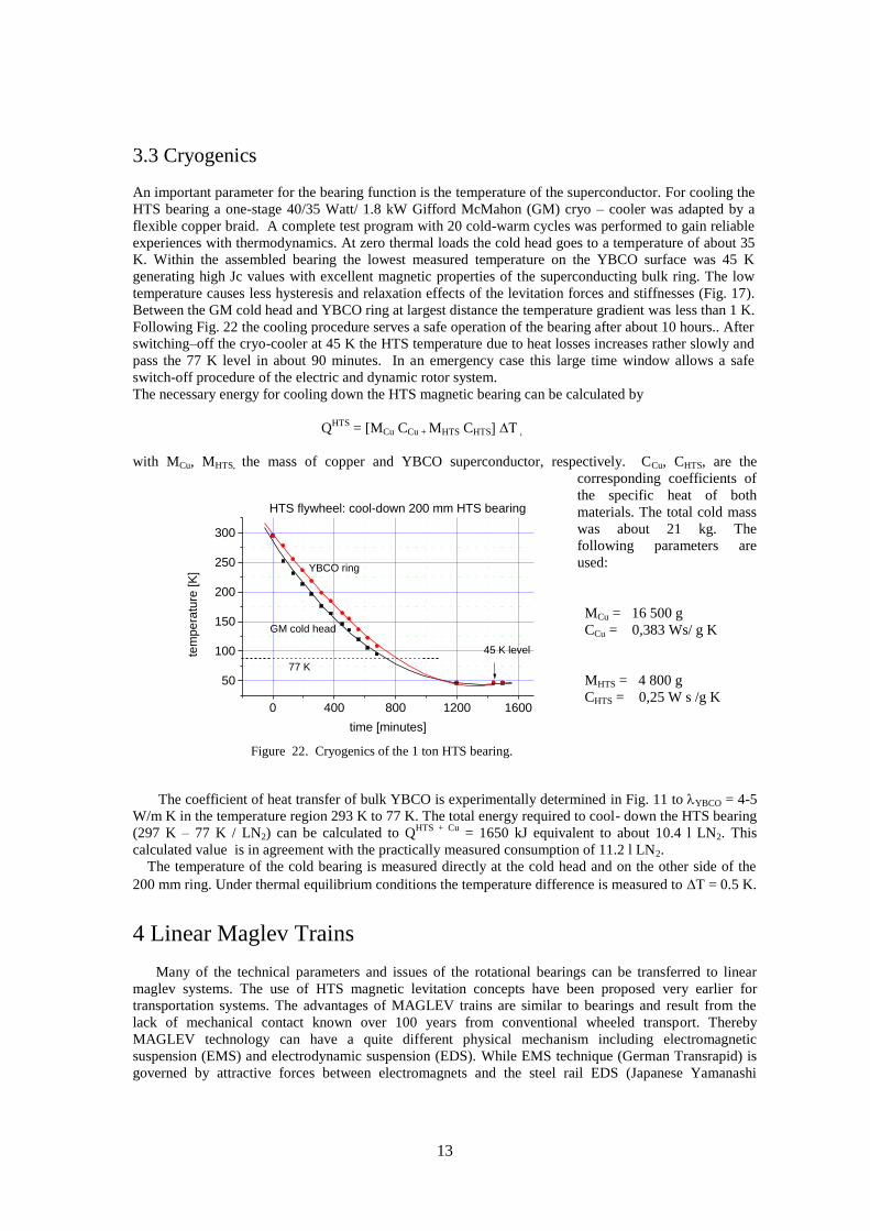
Figure 22. Cryogenics of the 1 ton HTS bearing.
3.3 Cryogenics
An important parameter for the bearing function is the temperature of the superconductor. For cooling the
HTS bearing a one-stage 40/35 Watt/ 1.8 kW Gifford McMahon (GM) cryo – cooler was adapted by a
flexible copper braid. A complete test program with 20 cold-warm cycles was performed to gain reliable
experiences with thermodynamics. At zero thermal loads the cold head goes to a temperature of about 35
K. Within the assembled bearing the lowest measured temperature on the YBCO surface was 45 K
generating high Jc values with excellent magnetic properties of the superconducting bulk ring. The low
temperature causes less hysteresis and relaxation effects of the levitation forces and stiffnesses (Fig. 17).
Between the GM cold head and YBCO ring at largest distance the temperature gradient was less than 1 K.
Following Fig. 22 the cooling procedure serves a safe operation of the bearing after about 10 hours.. After
switching–off the cryo-cooler at 45 K the HTS temperature due to heat losses increases rather slowly and
pass the 77 K level in about 90 minutes. In an emergency case this large time window allows a safe
switch-off procedure of the electric and dynamic rotor system.
The necessary energy for cooling down the HTS magnetic bearing can be calculated by
QHTS
= [MCu CCu + MHTS CHTS] ∆T ,
with MCu, MHTS, the mass of copper and YBCO superconductor, respectively. CCu, CHTS, are the
corresponding coefficients of
the specific heat of both
materials. The total cold mass
was about 21 kg. The
following parameters are
used:
MCu = 16 500 g
CCu = 0,383 Ws/ g K
MHTS = 4 800 g
CHTS = 0,25 W s /g K
The coefficient of heat transfer of bulk YBCO is experimentally determined in Fig. 11 to YBCO = 4-5
W/m K in the temperature region 293 K to 77 K. The total energy required to cool- down the HTS bearing
(297 K – 77 K / LN2) can be calculated to QHTS + Cu
= 1650 kJ equivalent to about 10.4 l LN2. This
calculated value is in agreement with the practically measured consumption of 11.2 l LN2.
The temperature of the cold bearing is measured directly at the cold head and on the other side of the
200 mm ring. Under thermal equilibrium conditions the temperature difference is measured to T = 0.5 K.
4 Linear Maglev Trains Many of the technical parameters and issues of the rotational bearings can be transferred to linear
maglev systems. The use of HTS magnetic levitation concepts have been proposed very earlier for
transportation systems. The advantages of MAGLEV trains are similar to bearings and result from the
lack of mechanical contact known over 100 years from conventional wheeled transport. Thereby
MAGLEV technology can have a quite different physical mechanism including electromagnetic
suspension (EMS) and electrodynamic suspension (EDS). While EMS technique (German Transrapid) is
governed by attractive forces between electromagnets and the steel rail EDS (Japanese Yamanashi
14
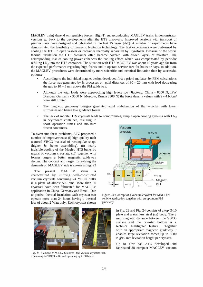
Figure 23: Concept of a vacuum cryostat for MAGLEV
vehicle application together with an optimum PM
guideway.
Fig. 24 Compact MAGLEV Stainless Steel vacuum cryostats each
containing 24 YBCO bulks and operating up to 30 hours.
MAGLEV train) depend on repulsive forces. High-Tc superconducting MAGLEV trains in demonstrator
versions go back to the developments after the HTS discovery. Improved versions with transport of
persons have been designed and fabricated in the last 15 years [4-7]. A number of experiments have
demonstrated the feasibility of magnetic levitation technology. The first experiments were performed by
cooling the HTS in open vessels or container thermally separated by Styrofoam. Because of the worse
thermal insulation the HTS container often became covered with frozen layers of moisture. The
corresponding loss of cooling power enhances the cooling effort, which was compensated by periodic
refilling LN2 into the HTS container. The situation with HTS MAGLEV was about 10 years ago far from
the expected performance regarding high forces and to operate service-free for hours or days. In addition,
the MAGLEV procedures were determined by more scientific and technical limitation than by successful
options:
• According to the individual magnet design developed first a priori and later by FEM calculations
the force was generated by fc processes at axial distances of 30 – 20 mm with load decreasing
the gap to 10 – 5 mm above the PM guideway.
• Although the total loads were approaching high levels too (Jiaotong, China - 8000 N, IFW
Dresden, Germany - 3500 N; Moscow, Russia 3500 N) the force density values with 2 - 4 N/cm²
were still limited.
• The magnetic guideway designs generated axial stabilization of the vehicles with lower
stiffnesses and hence low guidance forces.
• The lack of mobile HTS cryostats leads to compromises, simple open cooling systems with LN2
in Styrofoam container, resulting in
short operation times and moisture
frozen containers.
To overcome these problems, ATZ proposed a
number of improvements: (i) high quality melt
textured YBCO material of rectangular shape
(higher Jc, better assembling), (ii) nearly
invisible cooling of the Maglev HTS bulks by
means of vacuum cryostats, (iii) together with
former targets a better magnetic guideway
design. The concept and target for solving the
demands on MAGLEV side is shown in Fig. 23
The present MAGLEV status is
characterized by utilizing well-constructed
vacuum cryostats containing 24 YBCO bulks
in a plane of almost 500 cm². More than 30
cryostats have been fabricated for MAGLEV
application in China, Germany and Brazil. Due
to perfect thermal insulation each cryostat can
operate more than 24 hours having a thermal
loss of about 2 Watt only. Each cryostat shown
in Fig. 23 and Fig. 24 consists of a top G-10
plate and a stainless steel (ss) body. The 2
mm magnetic distance between the YBCO
surface and the cryostat bottom is a
technical highlighted feature. Together
with an appropriate magnetic guideway it
enables large levitation forces up to 3000
N@10 mm levitation height per cryostat.
Up to now has ATZ developed and
fabricated 38 compact MAGLEV vacuum

15
Figure 27: Larger MAGLEV demonstrator vehicles in Rio de Janeiro, Dresden and Chengdu (left - to - right)
Figure 25: Cross section of vacuum cryostat design for
MAGLEV application; HTS bulks are conduction
cooled with one-day operation time.
Fig. 26. Force measurement of a Maglev
cryostat for an optimized semi –Halbach
magnet configuration [19].
cryostats. Four HTS cryostats can carry almost 1 ton at 10 - 12 mm magnetic gap above a magnetic
guideway with a force density of about 5 -6 N/cm². In addition for Maglev operation ATZ has performed
FEM calculations to optimize the guideway PM configuration shown in Fig. 23. Fig. 23 exhibits a basic
configuration rule for the geometrical size of the PM and Fe collectors dependent of the chosen magnetic
gap distance g. Most of the used algorithm to
calculate the interaction with the superconductor
follows the critical state model. Improvements are
expected by using Halbach or semi – Halbach
magnet configurations. The optimum magnetic
configuration depends always on the actual gap
distance between superconductor and magnetic
surface, mostly selected to 10 mm distance. The
principle design of the high- gradient guideway
concept considers the magnetic distribution of the
principal vectors By and Bz following the rotational
bearing concept of Fig. 14.
Inside of each cryostat 24 multi-seeded YBCO
bulks of the dimension 64 mm x 32 mm x 12 mm
are located in a copper holder. The total HTS area is about 490 cm² per cryostat. The superconductors are
cooled using LN2 by conduction cooling.
As noticed the 2 mm magnetic distance between the YBCO surface and the cryostat bottom is a
technical challenge but successfully solved in a robust construction. It enables large levitation forces
respective a high load capacity. Cooling-down to
superconductivity is effective in about 30 minutes. Due
to a cryogenic storage capacity of 2.5 liter LN2 a long
operation is ensured. Our measurements of the LN2
consumption under static conditions indicate a 25 – 30
hours operation without refilling liquid Nitrogen.
The levitation forces depend strongly on the optimum
magnetic track configuration. Fig. 26 gives a picture of
the measured levitation of a YBCO cryostat on a semi-
Halbach PM configuration of the University of Rio de
Janeiro [6]
After the first Maglev operation about 15 years ago in
Chengdu now an 80 m long oval PM Germany (Fig.
27). The maglev is now more than 3 years active without
any degradation effects. Except the superconductor part
the Maglev demonstrator in Dresden possesses a
contactless current transformation and a linear motor
between the two efficient PM tracks for acceleration and
velocities up to 20 km/h. The total costs of the
MAGLEV train were about 2.2 million EURO.
A similar Maglev system with ATZ’s superconductor vacuum cryostats is designed, tested, and built -
up at the University of Rio de Janeiro, Brazil (Fig. 27, left photograph). The MAGLEV train, named
Maglev COBRA, is proposed to operate on 150 m long magnetic guideway transporting up to 15 persons.

16
The COBRA train is in the final stage magnetically levitated by 24 cryostats with a calculated total load of
5 tons.
In order to realize the possible high- speed potential of MAGLEV transport the ASC Lab/ Southwest
Jiaotong University in Chengdu has built a new 45 m circular PM track and investigate several potentially
commercial issues of MAGLEV transport systems including the influence of the air friction and possible
scaling up and miniaturization of MAGLEV technique (Fig. 27, right).
References
[1] Strasik M, Hull J R, Mittleider J, Gonder J, Johnson P, McCrary K, McIver C (2010), An overview
of Boeing flywheel energy storage systems with high-temperature superconducting bearings,
Supercond. Sci. Technol. 23.
[2] Koshizuka N, 2006 R&D of superconducting bearing technologies for flywheel energy storage
Systems, Physica C 445–448 1103.
[3] Werfel F N, Floegel-Delor U, Rothfeld R, Riedel T, Goebel B, Wippich D, and Schirrmeister P,
2012 “Superconductor bearings, Flywheels and Transportation”, Supercond. Sc. Technol.24,
014007.
[4] Wang J Wang Suyu, Zeng Y, Huang H, Luo, Xu Z, Tang O, Lin G, Zhang C, Ren Z, Zhao G, Zhu,
D, Wang S, Jiang H, Zhu M, Deng C, Hu P, Li C, Liu F, Lian J, Wang X, Wang L, Shen X, Dong X
2002 The first man-loading high temperature superconducting Maglev test vehicle in the world
Physica C 378-381 809.
[5] Schultz L, deHaas O, Verges P, Beyer C, Roehlig S, Olsen H, Kuehn L, Berger D, Noteboom Funk U
2005 Superconductively levitated transport system—The SupraTrans project IEEE Trans. Appl.
Supercond. 15 2301.
[6] Sotelo G G, Dias D H N, de Andrade R and Stephan R M 2011Tests on a superconductor linear
magnetic bearing of a full-scale Maglev vehicle 2011 IEEE Trans. Appl. Supercond. 21 1464–68.
[7] Z. Deng, J. Wang, J. Zheng, 2009, Performance advances of HTS Maglev vehicle system in three
essential aspects, IEEE Trans. Appl. Supercond.19,3, 2137-2141.
[8] Nariki S, Sakai N and Murakami M 2005 Melt-processed Gd–Ba–Cu–O superconductor with
trapped field of 3 T at 77 K Supercond. Sci. Technol. 18 S126.
[9] Oka T 2007 Processing and applications of bulk HTSC Physica C 463–465 7.
[10] Krabbes G, Bieger W, Schatzle P, and Wiesner U 1998 Improved HTSC bulk materials: a
thermodynamic approach to processing, Supercond. Sci. Technol. 11 144–148.
[11] Nariki S, Sakai N, Kita M, Fujikura M, Murakami M and Hirabayashi I 2006 Advances in
enlargement of melt-textured Gd–Ba–Cu–O superconductors Supercond. Sci. Technol. 19 S500.
[12] Oda M , Yao X, Yoshida Y, Ikuta H 2009 Melt-textured growth of (LRE)–Ba–Cu–O by a cold-
seeding method using SmBa2Cu3Oy thin film as a seed Supercond. Sci. Technol. 22 075012.
[13] Durrell J H, Dennis A R, Jaroszynski J, Ainslie M D, Palmer K G B, Shi Y-H, Campbell A M, Hull
J, Strasik M, Hellström E E and Cardwell D A, 2014, Supercond. Sci. Technol.27, 082001.
[14] Tomita M, Murakami M 2000 Improvement of the mechanical properties of bulk superconductors
with resin impregnation Supercond. Sci. Technol. 13 722. [15] Diko P, Antal V, Zmorayova K, Seficikova M, Chaud X, Kovac J, Yao Y, Chen I, Eisterer M , and Weber H M, Supercond. Sci. Technol. 23(2010)124003. [16] Muralidhar, N. Sakai, M. Jirsa, M. Murakami and L. Hirabayashi, Appl. Phys. Lett. 92, 162512
(2008).
[17] Seino H, Nagashima K, Tanaka Y, Nakauchi M, 2010 Study of Superconducting Magnetic Bearing
Application to the Flywheel Energy Storage System that consist of HTS bulk and
Superconducting coils, J. Phys. C Conf. Series, p. 1076.