document
DESCRIPTION
http://www.easyequipment.com/v/vspfiles/assets/images/User_Manual_EB3F.pdfTRANSCRIPT
IS09 ECN2087
1
LINCAT
EB3, EB4 & EB6 Automatic Fill Water Boilers
Installation, User & Servicing Instructions
IS09 ECN2087
2
Contents
Introduction 3
Accessories
Warnings and Precautions 4
Installation Preparation 5
Work Surfaces and Areas
Water Connection
Electrical Connection
Overflow and Drainage
Installation 6 - 9
Work Surface Installation
Wall Bracket Installation
Fixing the Wall Bracket to the Boiler
Fitting the Spillage Tray
Connection of the Water Supply
Overflow and Drainage
Electricity Supply
Commissioning the Appliance
Note to the Installation Engineer
User Instructions 10 - 11
Operating the Appliance
Cleaning
Scale
De-scaling the Appliance
Technical Specifications 12
Maintenance 13
Troubleshooting
Spare Parts 14 - 15
Tank assembly
Base assembly
Body assembly
Wiring and Circuit Diagrams 16 - 17
EB3 Wiring diagram
EB4 Wiring diagram
EB6 Wiring diagram
Circuit diagram
Spare Parts List 18
Replacing Parts 19 - 20
Thermostat
Contactor
Circuit board
Neon
Faucet
Tank
Protective device
Service 21
Authorised service agents
Guarantee

IS09 ECN2087
3
Introduction
Lincat automatic fill water boilers are designed for continuous operation and should only be
switched off for the purposes of maintenance or emergency.
Accessories The new boiler is supplied with the following components and should be verified before
installation.
• Approved flexible water connection hose.
• Pack of de-scaling compound.
• Spillage tray and grid.
• Instruction booklet.
• Guarantee card.
The EB3 model is supplied with a 3 pin bonded plug and lead fitted with a 13Amp fuse as
standard.
The EB range of boilers is surface mounted and carries the option of being wall mounted. Wall
fixing kits are an optional extra.
The EB range has a unique drainage system to allow for ease of tank evacuation during routine
de-scaling of the appliance. It is not necessary to invert the appliance during the de-scaling
procedure.
These instructions must be retained for safekeeping and for future reference.
Please read carefully all the instructions before commencing with the
installation and commissioning of the appliance.

IS09 ECN2087
4
Warnings and Precautions
Please read the following carefully before commencing work on this equipment.
A competent installation engineer, in accordance with the installation instructions of this
appliance and all relevant local and national standards including the following must install this
appliance:
• Health and Safety at Works Acts
• IEE regulations
• BS Codes of Practice
• Local and National Building Regulations
• Fire Precautions Act 1971
• EN 60335-1:1994, EN 60335-2-21:1999, EN 60335-2-63:1993, EN 60529:1992 and BS 3456
part 102 section 102.21:1988
It is mandatory that all appliances are installed, commissioned and serviced by a qualified
and competent person as defined by the regulations in force in the country of installation.
During normal use of the appliance certain surface areas will become hot. These areas are
especially in the vicinity of the facet and spigot. Care should be taken to avoid potential injury
from burns and scolding whilst operating the appliance.
Scale formation within hot water appliances is problematic and more so in hard water areas.
Damage to the appliance caused by excessive scale build up may invalidate the warranty – see
notes on de-scaling.
Use only the supplied parts with the appliance. Introducing foreign components not approved by
the manufacturer may cause tainting of the water and may also invalidate the warranty.
Do not place foreign objects in the tank of the appliance.
Parts explosion, circuit and wiring diagrams are the sole property of Lincat and must not be
reproduced without the consent of the manufacturer.

IS09 ECN2087
5
Installation Preparation
Work Surfaces and Areas • Ensure that the work surface upon which the appliance is to be sited is capable of sustaining
the working weight of the appliance.
• Consideration should be given for servicing requirements.
• Ensure that safe operational access to the appliance is unrestricted.
• Do not site the appliance directly beneath wall cupboards, other wall mounted appliances and
low ceilings that are susceptible to damage from water vapour.
• Where the appliance is to be wall mounted it is recommended that the safe working height
from the floor to the faucet is approximately 1400mm.
Water Connection • Connection to the cold water supply and the appliance is made via the hose supplied. The
hose can be found inside the tank of the appliance and must be removed before installation
and commissioning.
• In hard water areas it is advisable to fit a filtration unit to limit scale deposits. A filter kit is
available as an optional extra.
Electrical Connection • All electrical work must comply with all relevant wiring regulations and carried out by a
qualified electrician.
• EB3 models require a 13Amp-supply socket.
• EB4 models require a 20Amp supply.
• EB6 models require a 30Amp single or multi-phase supply.
• Isolation switches for the appliance must not be obstructed and be within easy reach.
Overflow and Drainage • Due to the electronic function of the water boiler it is highly unlikely than an overflow would
occur. The boiler is primarily designed so that any overflow occurrence and condensation is
directly vented to the spillage tray.
• As an option the boiler overflow outlet may be connected to a drainage system.
Note: There may some steam emissions from the vent at the base of the appliance during the
initial fill stages but the steam emissions will lessen as the volume of water increases in the tank.
As an alternative the internal flexible hose may be redirected. See notes on Overflow and
Drainage in the Installation section.
WARNING. The flexible hose connected from the over flow also acts as a vent for the appliance.
Under no circumstances should this flexible hose become blocked or restricted in any way.

IS09 ECN2087
6
Installation
Qualified personnel must carry out all installation work.
Work Surface Installation The work surface onto which the appliance is to be sited must have the relevant physical
properties to sustain the working weight of the relevant appliance.
Working Weights
EB3 30.5kg
EB4 34.5kg
EB6 46kg
EB6T 46kg
If water, electrical and drainage services are to be brought through the work surface ensure there
is sufficient cable slack, movement for the flexible inlet hose and drain tubing (optional) to allow
for free access maintenance and service personnel.
Where electrical sockets or electrical isolation points are fixed below the work surface then these
points must not be able to come into contact with water. Access to electrical isolating points must
not be obstructed in case of emergency. Instruction to the owner of the appliance must be given
on how to isolate the appliance in case of emergency.
The work surface must have a minimum depth of 600mm.
The spillage tray must be fitted with the appliance
EB6 dimensional details
EB4 dimensional details
EB3 dimensional details

IS09 ECN2087
7
FLOOR LEVEL
Wall Bracket Installation Where the appliance is to be mounted to a wall ensure the wall is constructed of a suitable
material to sustain the working weight of the boiler.
• To fit the wall bracket make a centre mark on the wall at approximately 1400mm from the
floor.
• In the orientation shown, align the hole in the centre rib of the wall bracket with the centre
mark on the wall.
• Ensuring the wall bracket is level, mark out the remaining holes.
• Drill 4 off 7mm diameter holes using a suitable masonry drill at a depth to
accommodate the wall-fixing plugs issued with the bracket.
• Fit the wall-fixing plugs and attach the wall bracket using the
screws issued with the wall bracket.
Fixing the Boiler to the Wall Bracket • Align the upper wall bracket tabs with the slots in the top of the
back panel on the boiler.
• Align the lower wall bracket tabs with the slots in the base of the boiler.
• Clip the boiler into place.
• The boiler must be secured to the base of the bracket using M5 screws.
Fitting the Spillage Tray Bracket • Remove the four feet from the base of the boiler.
• Secure the spillage tray bracket to the base of the boiler using the four feet fixing positions.
The bracket is to be fitted with M5 screws issued with the bracket. Longer screws may
damage components within the boiler and therefore invalidate the warranty.
• Fit the spillage tray to the bracket.
Do not attach electrical cables or water supply pipes to the wall bracket.
Connection of the Water Supply The minimum working pressure of the appliance is 20kPa (0.2Bar).
The maximum working pressure of the appliance is 1000kPa(10Bar).
• The appliance is to be plumbed to a suitable drinking water supply that complies with
national Water Bylaws.
• The recommended connection is made via the
flexible hose supplied with the appliance. The
fittings are ¾" BSP.
• The main water supply must have a double check
valve fitted.
• It is advisable to fit an isolation valve to the main
water supply and that where possible the flexible
hose is connected directly to it before connection
to the appliance is made. There must be
unrestricted access to the isolating valve.
• To minimise the scale build up in hard water areas
the optional filter kit may be connected between the
water isolating valve and the appliance.

IS09 ECN2087
8
• Connection of the appliance to the water supply must also allow for reasonable service access
unless the appliance is situated in high-risk areas.
Overflow and Drainage
• The overflow from the tank is connected via a flexible tube to a vent port mounted internally
of the appliance.
• The primary function of this feature is to capture the small amounts of condensed steam
produced during normal operation of the appliance.
• In the unlikely event of an overflow occurrence the spillage tray has a limited capacity and
should not be deemed as a safeguard against overflow.
• As an option the flexible tube can be removed from the lower internal vent and redirected
through the base to a suitable drainage system.
• The drainage system to which the flexible tube is to be connected must have a continuous fall
and have a greater diameter than that of the flexible tube. Alternatively, the flexible tube can
be directed to a gully where no risk of contact with hot water by persons using the building
can be considered as a means of safe drainage.
• The flexible tube must not be connected directly to a soil system.
• The tube from the overflow must remain connected to the overflow on the tank.
• The overflow tube must never become blocked or restricted in any way.
Electricity Supply All appliances must be earthed.
The EB3 model is supplied with a 3 pin bonded plug and lead fitted with a 13Amp fuse as
standard. The plug is to be connected to a suitable mains socket. The wiring markings are as
follows: -
LIVE wire colour BROWN with terminal marked L
NEUTRAL wire colour BLUE with terminal marked N
EARTH wire colour GREEN/YELLOW with terminal marked E or
All appliances with an electrical loading of over 3kW must be connected to the supply by a
qualified electrician in accordance with Health & Safety at Works Act, IEE regulations, BS codes
of practice, Building Standards, Local Authority and Building regulations etc. A suitable means
of disconnecting such units from the supply must be provided, having at least 3mm contact
separation at all poles.
The EB4 model should be wired to at least a 20Amp single-phase supply via an isolation switch.
The isolation switch must be so positioned for immediate access in case of emergency shut down.
The EB6 model should be wired to at least a 30Amp single phase or multi-phase supply via an
isolation switch. The isolation switch must be so positioned for immediate access in case of
emergency shut down.
• To wire the EB4 and EB6 models remove the access panel at the rear of the appliance.
• Remove the TEST WIRES from the terminal block and cable gland.
• For EB6 models to be wired from a multi-phase supply remove the LINK wire from the
terminal block.
• Introduce the new cable from the isolation switch to the appliance via the cable gland and
wire to the terminal block as follows:-

IS09 ECN2087
9
LIVE wire colour BROWN with terminal marked L
NEUTRAL wire colour BLUE with terminal marked N
EARTH wire colour GREEN/YELLOW with terminal marked E or
• Secure all wiring and connections.
• Replace the access panel.
• Electrically test the appliance.
Commissioning the Appliance • Remove all protective plastic coating.
• Check that the drain down valve is closed.
• Ensure that the upper and lower level sensors are in a vertical position.
• Ensure that all lids are fitted correctly.
• Ensure that the faucet is in the closed position.
• With all appropriate services connected turn on the water supply.
• Switch on the electricity supply. The illumination of the green neon will signify "power on"
to the appliance.
• The appliance will now begin to fill with water.
• Upon the water reaching the lower element sensor the solenoid will close and the element(s)
will begin to heat the water.
• Approximate heating times for the initial fill is: -
EB3 – 12 minutes EB4 – 9 minutes EB6 – 9 minutes
• After the initial fill allow a further 5 minutes after which approximately 1liter of hot water
will be available for use.
• Upon reaching maximum temperature the appliance will call for more water. This is the start
of the cycle.
• The appliance will continue to cycle until the water level reaches the upper level sensor.
• Approximate fill cycle times from the lower sensor to the upper sensor are: -
EB3 – 27 minutes EB4 – 32 minutes EB6 – 35 minutes
• Upon the water reaching the upper level sensor the appliance will switch into standby mode.
• As hot water is drawn off, the appliance will automatically begin to cycle until the water
reaches the upper level sensor.
Note to Installation Engineer • Instruct the end user on the operating features of the appliance.
• Instruct the end user how to isolate all services in case of emergency.
• Instruct the end user on cleaning and de-scaling of the appliance.
• Advise the end user that these instructions should be retained for safekeeping.

IS09 ECN2087
10
User Instructions • Retain these instructions for future reference.
• Ensure that the spillage tray is in the correct position before operating the appliance.
• Care should be taken to avoid injury whilst operating the appliance at the water temperature is
maintained at approximately 98 oC.
• Only qualified personnel should attempt any routine or necessary maintenance work on the
appliance.
Operating the Appliance • Place a cup or suitable hot water container, central to the tap, upon the spillage tray.
• To draw off hot water, pull the faucet handle towards the user. Hot water will be dispensed at
a steady flow until the water capacity is reduced to the level of the spigot. Upon releasing the
faucet handle, the handle will return to the closed position.
• For larger containers the faucet handle may be pulled to the horizontal position thereby
locking the faucet open. The faucet handle will then have to be manually returned to the
closed position. Warning. Whilst the faucet handle is in the locked open position the
appliance must not be left unattended.
• As hot water is drawn off the appliance will automatically begin the fill cycle. The filling
cycle will continue until the appliance goes into standby mode. The length of the fill time to
full capacity depends upon the volume of hot water drawn off.
• Do not remove the lids from the appliance whilst in full operation as these parts become hot.
Cleaning
To clean the appliance use only a soft damp cloth and mild detergent. Do not us abrasives on the
mirror-finished surfaces as damage may result. Care should be taken when cleaning outer
surfaces whilst the appliance is in full operation as certain areas become hot during normal
operation.
It will be necessary from time to time during normal operation to inspect the spillage tray for
water. Empty the spillage tray as and when necessary.
Warning. The appliance is not protected against the ingress of water. The appliance must not be
submerged for cleaning purposes. Do not use water jet spray cleaning equipment on the
appliance. The appliance is splash protected and has the code IP24B.
Scale
The formation of scale within a hot water system is common and if left unchecked may cause
problems to the functioning of the appliance. In hard water areas scale formation builds up
quicker than in softer water areas therefore checks on scale formation need to be more frequent. It
is advisable, in order to prevent injury, the appliance be isolated and allowed to cool before
inspecting for scale deposits within the tank.
Warning. Under no circumstances should this appliance be connected to the outlet of a water
softener.
Please note that the manufactures guarantee will be void if faults arise which are due to excessive
build up of scale.
To help prevent scale build up a filter system can be installed with the appliance. The filter is
available as an optional extra upon request.
IS09 ECN2087
11
De-scaling the Appliance
It is recommended that the appliance be de-scaled regularly. Excessive scale deposits may
become difficult to remove with some de-scaling products.
• To de-scale the appliance, isolate the appliance from the water and electricity supply.
• Allow the water to cool to prevent possible injury when removing parts.
• Remove the outer and inner lids.
• Add the de-scaling compound, a little at a time, to the cooled water. Some de-scaling
compounds may cause hot water to erupt. It is advisable to follow the instructions of the
manufacturers.
• Replace the inner and outer lids of the appliance.
• Turn on the water and electricity supply.
• Allow the appliance to heat and run in standby mode for approximately 30 minutes, after
which, isolate the services and allow the water to cool.
• Remove the lid system and inspect the tank for scale deposits. In the case of severe scale
deposits it may be necessary to repeat the de-scaling process.
• On completion of successful de-scaling, evacuate the tank via the faucet. To complete the
evacuation of the tank, move, if possible, the appliance so that the leading edge of the
appliance over hangs the work surface not exceeding 30mm. Place a suitable container
directly below the appliance over hang to capture the discharge from the tank. If it is not
possible to move the appliance on the work surface the remaining contents of the tank can be
drained into the spillage tray. Note. The spillage tray has a small limited capacity. Where the
appliance is wall mounted the container can be placed beneath the appliance.
• Examine the level sensor housings for scale build up and other deposits, clean as necessary.
Failure to do so may incur problems with tracking from sensor housing to the tank wall
thereby giving false signals to the circuit board and ultimately cause failure of the appliance.
• Insert a flat bladed screwdriver into the drain valve screw and rotate anti-clockwise to loosen
the screw. Continue to rotate the screw anti-clockwise until a steady flow is observed from
the valve.
• Evacuate the tank completely and close the valve by rotating the valve screw clockwise.
Ensure the valve screw is fully home.
• It will be necessary to purge the tank, turn on the water and electricity supply and allow the
appliance to fill. Do not fill the tank manually with water as spillage may damage the
electrical components of the appliance and therefore invalidate the warranty.
• Drain the tank as described above and refill the appliance.
• If the water is free of tainting that may be caused by the use of some de-scaling compounds
then the appliance is ready for use.
IS09 ECN2087
12
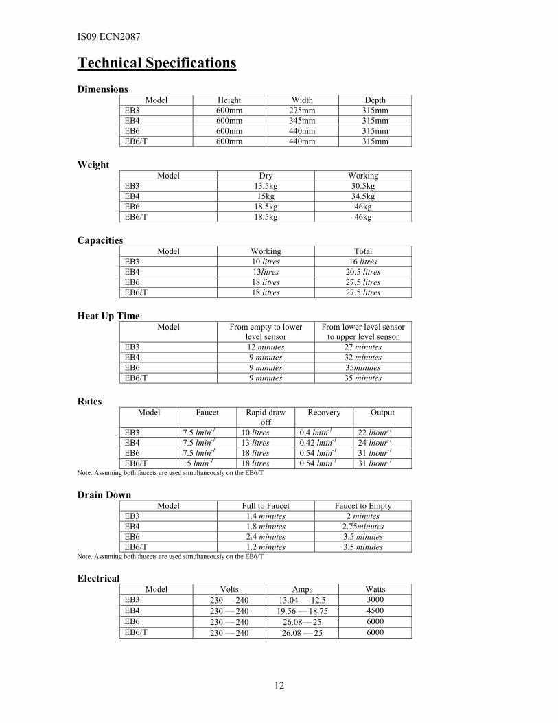
Technical Specifications
Dimensions Model Height Width Depth
EB3 600mm 275mm 315mm
EB4 600mm 345mm 315mm
EB6 600mm 440mm 315mm
EB6/T 600mm 440mm 315mm
Weight Model Dry Working
EB3 13.5kg 30.5kg
EB4 15kg 34.5kg
EB6 18.5kg 46kg
EB6/T 18.5kg 46kg
Capacities Model Working Total
EB3 10 litres 16 litres
EB4 13litres 20.5 litres
EB6 18 litres 27.5 litres
EB6/T 18 litres 27.5 litres
Heat Up Time Model From empty to lower
level sensor
From lower level sensor
to upper level sensor
EB3 12 minutes 27 minutes
EB4 9 minutes 32 minutes
EB6 9 minutes 35minutes
EB6/T 9 minutes 35 minutes
Rates Model Faucet Rapid draw
off
Recovery Output
EB3 7.5 lmin-1 10 litres 0.4 lmin-1 22 lhour-1
EB4 7.5 lmin-1 13 litres 0.42 lmin-1 24 lhour-1
EB6 7.5 lmin-1 18 litres 0.54 lmin-1 31 lhour-1
EB6/T 15 lmin-1 18 litres 0.54 lmin-1 31 lhour-1 Note. Assuming both faucets are used simultaneously on the EB6/T
Drain Down Model Full to Faucet Faucet to Empty
EB3 1.4 minutes 2 minutes
EB4 1.8 minutes 2.75minutes
EB6 2.4 minutes 3.5 minutes
EB6/T 1.2 minutes 3.5 minutes Note. Assuming both faucets are used simultaneously on the EB6/T
Electrical Model Volts Amps Watts
EB3 230 240 13.04 12.5 3000
EB4 230 240 19.56 18.75 4500
EB6 230 240 26.08 25 6000
EB6/T 230 240 26.08 25 6000
IS09 ECN2087
13
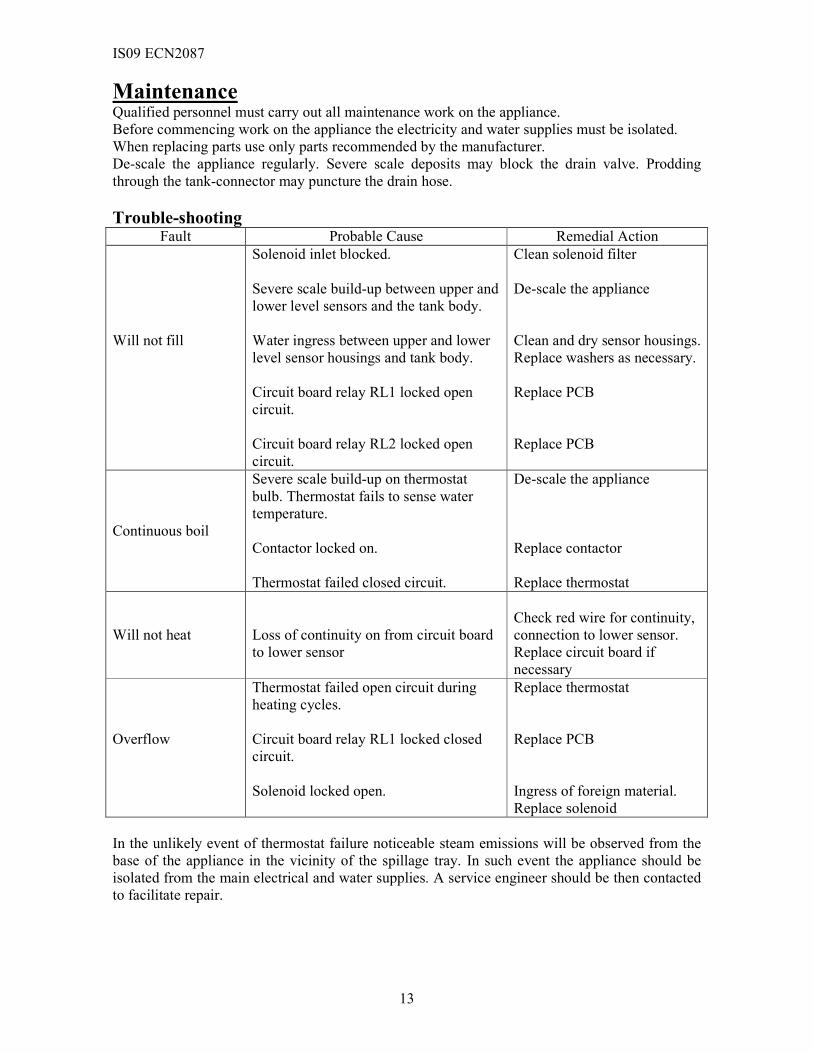
Maintenance Qualified personnel must carry out all maintenance work on the appliance.
Before commencing work on the appliance the electricity and water supplies must be isolated.
When replacing parts use only parts recommended by the manufacturer.
De-scale the appliance regularly. Severe scale deposits may block the drain valve. Prodding
through the tank-connector may puncture the drain hose.
Trouble-shooting Fault Probable Cause Remedial Action
Will not fill
Solenoid inlet blocked.
Severe scale build-up between upper and
lower level sensors and the tank body.
Water ingress between upper and lower
level sensor housings and tank body.
Circuit board relay RL1 locked open
circuit.
Circuit board relay RL2 locked open
circuit.
Clean solenoid filter
De-scale the appliance
Clean and dry sensor housings.
Replace washers as necessary.
Replace PCB
Replace PCB
Continuous boil
Severe scale build-up on thermostat
bulb. Thermostat fails to sense water
temperature.
Contactor locked on.
Thermostat failed closed circuit.
De-scale the appliance
Replace contactor
Replace thermostat
Will not heat
Loss of continuity on from circuit board
to lower sensor
Check red wire for continuity,
connection to lower sensor.
Replace circuit board if
necessary
Overflow
Thermostat failed open circuit during
heating cycles.
Circuit board relay RL1 locked closed
circuit.
Solenoid locked open.
Replace thermostat
Replace PCB
Ingress of foreign material.
Replace solenoid
In the unlikely event of thermostat failure noticeable steam emissions will be observed from the
base of the appliance in the vicinity of the spillage tray. In such event the appliance should be
isolated from the main electrical and water supplies. A service engineer should be then contacted
to facilitate repair.

IS09 ECN2087
14
Spare Parts Before removing and replacing any part on the appliance the appliance must be isolated from the
water and electricity supply.
Replacement of parts must be parts approved by the manufacturer.
Some parts are not shown in the parts explosion diagrams, as they are non-serviceable.
Tank Assembly
Note: The tank lid is inclusive with the tank when the tank is ordered as a spare part.
Tank bodies are separate from all other items detailed.

IS09 ECN2087
15
Base Assembly
Body Assembly
The body manufactured as a complete part, panels
are not available separately.
The lid bezel is fitted to the lid; clips are
required in the fitting.
The tap bezel is screwed to the bodywork.
The neon lens and neon housing are serviceable
parts.
Tap nut (SL20) and circlip (SL21) are not
shown.

IS09 ECN2087
16
Wiring and Circuit Diagrams
EB3 Wiring Diagram
EB4 Wiring Diagram
NEON

IS09 ECN2087
17
EB6 Wiring Diagram
For multi-phase wiring of the EB6, remove the link wire at L1 & L2.
Circuit Diagram
The circuit diagram above is essentially for the EB3 as the element is powered via the thermostat.
For the EB4 and EB6 switching of the contactor that powers the element(s) is made via the
thermostat.
IS09 ECN2087
18
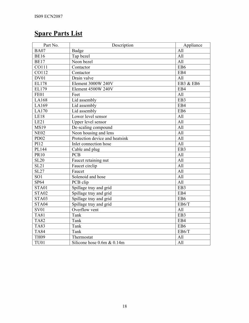
Spare Parts List
Part No. Description Appliance
BA07 Badge All
BE16 Tap bezel All
BE17 Neon bezel All
CO111 Contactor EB6
CO112 Contactor EB4
DV01 Drain valve All
EL178 Element 3000W 240V EB3 & EB6
EL179 Element 4500W 240V EB4
FE01 Feet All
LA168 Lid assembly EB3
LA169 Lid assembly EB4
LA170 Lid assembly EB6
LE18 Lower level sensor All
LE21 Upper level sensor All
MS19 De-scaling compound All
NE02 Neon housing and lens All
PD02 Protection device and heatsink All
PI12 Inlet connection hose All
PL144 Cable and plug EB3
PR10 PCB All
SL20 Faucet retaining nut All
SL21 Faucet circlip All
SL27 Faucet All
SO1 Solenoid and hose All
SP64 PCB clip All
STA01 Spillage tray and grid EB3
STA02 Spillage tray and grid EB4
STA03 Spillage tray and grid EB6
STA04 Spillage tray and grid EB6/T
SV01 Overflow vent All
TA81 Tank EB3
TA82 Tank EB4
TA83 Tank EB6
TA84 Tank EB6/T
TH09 Thermostat All
TU01 Silicone hose 0.6m & 0.14m All

IS09 ECN2087
19
Replacing Parts
Before removing and replacing any part on the appliance the appliance must be isolated from the
water and electricity supply.
Replacement of parts must be parts approved by the manufacturer.
Thermostat • Remove the outer lid.
• Remove the retaining screws from the back panel and slide the back panel vertically upward.
• Remove the retaining screws from the access panel.
• Loosen the thermostat gland and withdraw the thermostat bulb through the union.
• Remove the wires from the thermostat terminals, noting the connections.
• Loosen the thermostat retaining screws and remove the thermostat.
• Fit the new thermostat and assemble in reverse order.
• Electrically test the appliance.
Contactor • Remove the retaining screws from the access panel.
• Remove the wires from the contactor terminals, noting the connections.
• Spring the contactor-retaining clip to free the contactor from the bracket.
• Fit the new contactor, ensuring the contactor is fully seated on the bracket, and assemble in
reverse order.
• Electrically test the appliance.
Solenoid • Drain the tank as described earlier in the de-scaling routine.
• Remove the retaining screws from the access panel.
• Loosen the solenoid retaining screws.
• Loosen the pipe clip.
• Remove the wires from the solenoid terminals, noting the connections.
• Withdraw the solenoid. There may be a small quantity of water remaining in the hose.
• Fit the new solenoid and assemble in reverse order.
• Electrically test the appliance.
Circuit Board • Remove the outer lid.
• Remove the retaining screws from the back panel and slide the back panel vertically upward.
• Remove the retaining screws from the access panel.
• Remove the wires from the solenoid, contactor/thermostat, neon, terminal block, and element,
upper and lower sensors. Note: To free the wires from the neon, loosen the tank-retaining
bracket and ease that tank backward to gain access to the neon housing.
• Free the circuit board from the mounting clips.
• Fit the new circuit board and assemble in reverse order. Attention must be given to the wiring
on the level sensors.
• Electrically test the appliance.

IS09 ECN2087
20
Neon
• Remove the outer lid.
• Remove the retaining screws from the back panel and slide the back panel vertically upward.
• Remove the retaining screws from the access panel.
• Loosen the tank-retaining bracket and ease that tank backward to gain access to the neon
housing. Note: Remove any additional parts as necessary in order to move the tank.
• Remove the wires from the neon terminals.
• Depress the neon housing and slide the housing free from the lens. Note: The lens will be free
to be extracted from the neon bezel.
• Fit the new neon housing and assemble in reverse order.
• Electrically test the appliance.
Faucet • Evacuate the tank to the level of the faucet. Partially drain the tank as described in the de-
scaling routine.
• Loosen the faucet-retaining nut and remove the faucet. Note: To remove the faucet-retaining
nut, remove the circlip.
• Fit the new faucet and assemble in reverse order.
Tank
• Drain the tank as described earlier in the de-scaling routine.
• Remove the faucet.
• Remove the outer lid.
• Remove the retaining screws from the back panel and slide the back panel vertically upward.
• Remove the retaining screws from the access panel.
• Free the contactor/thermostat from the mounting bracket and remove the tank-retaining
bracket.
• Remove the middle and inner lids.
• Remove the drain hose from the tank connector.
• Remove the overflow hose form the tank vent pipe.
• Loosen the solenoid retaining screws.
• Remove the wires from the solenoid terminals, noting the connections.
• Remove the wires from the level sensors.
• Withdraw the tank.
• Remove the tank connector, level sensors and fit to the new tank.
• Fit the new tank and assemble in reverse order.
• Electrically test the appliance.
Protective Device •••• Remove the back panel.
•••• Disconnect the wires from the protective device.
•••• Loosen the element retaining nuts.
•••• Remove the heat sink and protective device.
•••• Fit the new device and assemble in reverse order.
•••• Electrically test the appliance.

IS09 ECN2087
21
Service
LINCAT GROUP SERVICE HELP DESK
� 01522 875520
AUTHORISED SERVICE AGENTS We recommend that all servicing other than routine cleaning be carried out by our authorised
service agents.
We cannot accept responsibility for work carried out by other persons.
Please quote both the model and serial numbers from the data plate attached to the unit. Give
brief details of the service requirement.
If possible please quote the product code of the part number you require.
GUARANTEE STATEMENT
Lincat Ltd guarantees its equipment to be free from defects in materials and workmanship for a period of 1 (one) year commencing from the date of purchase from the dealer, by the original owner. This guarantee is limited to the repair of defects, without charge, by a factory authorised service company or one of its service companies within normal working hours. Monday – Friday, 8.30am – 5.15pm. We undertake to visit site within 48 hours of the service call being placed, excluding weekends and bank holidays. This guarantee is not effective if damage occurs from; improper installation, misuse, incorrect voltage supply, wear and tear from normal usage, accidental breakage / damage or the equipment is operated contrary to the user instructions. Any expenses in connection with the installation or cost of making adjustments on the equipment to comply with the supply at the point of installation are not covered by this guarantee. The foregoing guarantee is in lieu of any and all other guarantees expressed or implied, and constitutes the entire guarantee.