huawei response to acma’s paper - acma.gov.au/media/spectrum transformation and... · huawei...
TRANSCRIPT
Huawei Response to ACMA’s paper:
Towards 2020 – Future spectrum
requirements for mobile broadband
HUAWEI TECHNOLOGIES CO., LTD.

ACMA “Towards 2020” Feedback
Copyright © Huawei Technologies Co., Ltd. 2011. All rights reserved.
No part of this document may be reproduced or transmitted in any form or by any means without prior written consent of Huawei Technologies Co., Ltd.
Trademarks and Permissions
and other Huawei trademarks are trademarks of Huawei Technologies Co., Ltd. All other trademarks and trade names mentioned in this document are the property of their respective holders. Notice
The purchased products, services and features are stipulated by the commercial contract made between Huawei and the customer. All or partial products, services and features described in this document may not be within the purchased scope or the usage scope. Unless otherwise agreed by the contract, all statements, information, and recommendations in this document are provided “AS IS” without warranties, guarantees or representations of any kind, either express or implied. The information in this document is subject to change without notice. Every effort has been made in the preparation of this document to ensure accuracy of the contents, but all statements, information, and recommendations in this document do not constitute the warranty of any kind, express or implied.
Enquires about this document may be sent to:
Jeremy Mitchell, Director of Corporate and Public Relations Email: [email protected] Phone: +61- 423576325
Huawei Technologies Co., Ltd.
Address: Huawei Industrial Base Bantian, Longgang Shenzhen 518129 People's Republic of China
Website: http://www.huawei.com

ACMA “Towards 2020” Feedback
TABLE OF CONTENTS
1 Introduction ................................................................................................... 4
2 MBB Demand and Supply ............................................................................... 4
2.1 Comments On Estimating MBB Demand.............................................................................................. 4
2.2 Key Points on MBB Spectrum Supply ................................................................................................... 5
2.3 Spectral Efficiency 2015 ....................................................................................................................... 6
2.4 Spectral Efficiency 2020 ....................................................................................................................... 7
3 Medium Term Technology Innovations (2015) ................................................ 7
3.1 Flatter Architectures ............................................................................................................................. 7
3.2 LTE and LTE-Advanced .......................................................................................................................... 7
3.2.1 LTE ................................................................................................................................................................. 7
3.2.1.1 Capacity Improvements Over HSPA+ .......................................................................................................................7
3.2.1.2 Antenna Techniques ................................................................................................................................................7
3.2.1.3 MIMO Implementation Considerations ...................................................................................................................8
3.2.1.4 Interference Management Techniques....................................................................................................................8
3.2.2 LTE-Advanced ................................................................................................................................................ 8
3.2.2.1 Carrier Aggregation (CA) ..........................................................................................................................................8
3.2.2.2 Multi Antenna (MIMO) Improvements ....................................................................................................................9
3.2.2.3 CoMP ─ Coordinated Multi-point Tx&Rx ...........................................................................................................10
3.2.2.4 Heterogeneous Network (HetNet) .........................................................................................................................10
3.2.2.5 Relay ......................................................................................................................................................................12
3.3 TDD versus FDD .................................................................................................................................. 12
4 Long Term Technology Innovations (2020) .................................................... 13
5 Conclusion .................................................................................................... 15

ACMA “Towards 2020” Feedback
1 Introduction
This paper is provided to ACMA in response to their discussion paper “ Towards 2020 – Future spectrum requirements for mobile broadband”. As a leading vendor of mobile broadband equipment, Huawei takes a keen interest in the development of new and existing spectrum bands around the globe suitable for mobile broadband (MBB). Huawei believes broadband is an important economic enabler and that mobile broadband plays an important part in this through its ubiquitous reach and flexibility. As many other parties will provide comment on the specifics of spectrum bands for Australia, in-line with ACMAs requests to understand the available technologies better, Huawei‟s comments for this paper will mostly focus on the capabilities of future technologies through 2015 and up to 2020.
2 MBB Demand and Supply
Predicting future demand for mobile broadband services is arguably more art than science such is the uncertainty of demand and the effect of market and technology innovations on growth rates. Even so, the global mobile industry has been reasonably prescient in anticipating significant demand (particularly driven by video content) and is developing new technologies such as LTE to help meet the demand.
2.1 Comments On Estimating MBB Demand
There are many industry estimates for future MBB growth available and generally they all indicate a large increase in demand. A common view across the industry and one Huawei observes in general is that MBB traffic is approximately doubling every year as shown in Figure 1.
Figure 1. MBB Traffic Growth
In determining how this demand will drive requirements for more spectrum, it can be reasonably concluded that demand by 2020 will challenge regulators ability to free up new spectrum. Even so, when applying industry estimates to this process some care needs to be taken. Growth rates and data
Traffic doubling in both past and future 3 years
-
1,000,000.00
2,000,000.00
3,000,000.00
4,000,000.00
5,000,000.00
6,000,000.00
7,000,000.00
USA CANADA UK Japan
2008
2009
2010
2011E
2012E
2013E
2014E
Source: Huawei Wireless 2011 Q1
ACMA “Towards 2020” Feedback
per user differ significantly from country to country and operator to operator. For example, ECC PT1 data1 showed that the average daily MBB data per user varied greatly across developed European countries. In 2009 Sweden had 61MB/sub/day, Denmark 43MB/sub/day and Germany 4.8MB/sub/day.
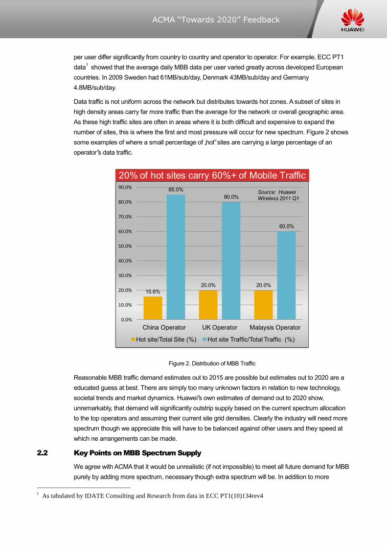
Data traffic is not uniform across the network but distributes towards hot zones. A subset of sites in high density areas carry far more traffic than the average for the network or overall geographic area. As these high traffic sites are often in areas where it is both difficult and expensive to expand the number of sites, this is where the first and most pressure will occur for new spectrum. Figure 2 shows some examples of where a small percentage of „hot‟ sites are carrying a large percentage of an operator‟s data traffic.
Figure 2. Distribution of MBB Traffic
Reasonable MBB traffic demand estimates out to 2015 are possible but estimates out to 2020 are a educated guess at best. There are simply too many unknown factors in relation to new technology, societal trends and market dynamics. Huawei‟s own estimates of demand out to 2020 show, unremarkably, that demand will significantly outstrip supply based on the current spectrum allocation to the top operators and assuming their current site grid densities. Clearly the industry will need more spectrum though we appreciate this will have to be balanced against other users and they speed at which ne arrangements can be made.
2.2 Key Points on MBB Spectrum Supply
We agree with ACMA that it would be unrealistic (if not impossible) to meet all future demand for MBB purely by adding more spectrum, necessary though extra spectrum will be. In addition to more
1 As tabulated by IDATE Consulting and Research from data in ECC PT1(10)134rev4
20% of hot sites carry 60%+ of Mobile Traffic
15.6%20.0% 20.0%
85.0%80.0%
60.0%
0.0%
10.0%
20.0%
30.0%
40.0%
50.0%
60.0%
70.0%
80.0%
90.0%
China Operator UK Operator Malaysis Operator
Hot site/Total Site (%) Hot site Traffic/Total Traffic (%)
Source: HuaweiWireless 2011 Q1

ACMA “Towards 2020” Feedback
spectrum, improvements in spectral efficiency and greater site density will be required to meet this future capacity challenge.
In regard to future spectral efficiency improvements, Huawei advises care in the assumptions used. The peak spectral efficiency is usually only achieved over a small percentage of the coverage area due to high modulation rates requiring high SINR. The actual spectral efficiency over the coverage area is necessarily much less. As outlined in ITU-R M.2078, a useful measure of spectral efficiency is area spectral efficiency which is defined as:
In Recommendation ITU-R M.1768 and Report ITU-R M.2074 the spectral efficiency is defined to be calculated from the mean data throughput achieved over all users, which are homogenously distributed in the area of the radio environment, on IP layer for packet switched services and on application layer for circuit switched services.
2.3 Spectral Efficiency 2015
Table 1 and Table 2 show the spectral efficiencies suggested for IMT-A and 3GPP LTE-A which takes us into the 2013~2015 timeframe. Rather than assuming 15bps/Hz which is a peak figure, we recommend the average spectral efficiency be used when mapping traffic demand to spectrum requirements. And as we noted above, high traffic sites (i.e. urban sites) may be the first to run out of spectrum so from 3GPP TR 36.912 V9.1.0 we have:
Table 1. Downlink spectral efficiency (FDD), Uma
Scheme and antenna
configuration
ITU
Requirement
(Ave./Edge)
Number
of
samples
Cell average
[b/s/Hz/cell] Cell edge [b/s/Hz]
L=1 L=2 L=3 L=1 L=2 L=3
MU-MIMO 4 x 2 (C) 2.2 / 0.06 7 2.8 2.6 2.4 0.079 0.073 0.066
CS/CB-CoMP 4 x 2 (C) 2.2 / 0.06 6 2.9 2.6 2.4 0.081 0.074 0.067
JP-CoMP 4 x 2 (A) 2.2 / 0.06 1 3.0 2.7 2.5 0.080 0.073 0.066
CS/CB-CoMP 8 x 2 (C) 2.2 / 0.06 3 3.8 3.5 3.2 0.10 0.093 0.084
Table 2. Uplink spectral efficiency (FDD), Uma
Scheme and antenna
configuration
ITU
Requirement
(Ave./Edge)
Number of
samples
Cell average
[b/s/Hz/cell]
Cell edge
[b/s/Hz]
Rel-8 SIMO 1 x 4(C) 1.4 / 0.03 12 1.5 0.062
CoMP 1 x 4 (A) 1.4 / 0.03 2 1.7 0.086
CoMP 2 x 4 (C) 1.4 / 0.03 1 2.1 0.099
The later section in this paper on LTE-A technology briefly discusses the new technologies introduced by LTE-A (referred to in the tables above) and how these assist to improve network capacity.
ACMA “Towards 2020” Feedback
2.4 Spectral Efficiency 2020
Huawei is a key player in defining the new technologies that will deliver the industry higher spectral efficiencies. When considering what spectral efficiencies might be possible by 2020 this is still very much the subject of research but we can postulate that a average spectral efficiency of 8bps/Hz might be possible. Refer to Section 4 Long Term Technology Innovations (2020).
3 Medium Term Technology Innovations (2015)
Huawei believes that the 3GPP family of technologies will be the main global mobile technology for the foreseeable future and certainly the most relevant to Australia. This set of standards has achieved widespread global operator acceptance and adoption and has a healthy ecosystem of suppliers supporting manufacturing and ongoing innovation. While technologies from other standards bodies such as the IEEE will play a role in wireless, high capacity wide area solutions will mostly be based on LTE and its evolution such as LTE-advanced.
3.1 Flatter Architectures
Future mobile network architectures will be characterized by a move to a flatter all IP architecture. From a spectrum perspective, moving voice from CS to IP will see greater efficiency in the delivery of voice traffic which will essentially become just another application, albeit a still valuable one. For example, an R99 cell may have a maximum of 80 voice users (code limited), HSPA R7 may support in the order of 115 VoIP users and LTE (per 5MHz) over 200 VoIP users per cell (based on simulations).
3.2 LTE and LTE-Advanced
3.2.1 LTE
3.2.1.1 Capacity Improvements Over HSPA+
LTE introduces a new air interface based on OFDMA and MIMO technologies. The advantage of LTE over HSPA+ is not so much concerned with peak speeds but rather real world capacity. For example, assuming the same RF system parameters2, a SIMO HSPA+ and SIMO LTE system in 5MHz will have similar peak speeds, around 21Mbps, but in a typical urban/suburban environment the LTE cell will have between 20% and 30% more capacity. In particular, cell edge users will fare better with LTE as it distributes capacity more evenly across the cell. If we look at the case of HSPA+ MIMO and LTE MIMO (both 2x2) the advantage of LTE is even greater with a 30% to 40% capacity improvement. For the uplink, the LTE capacity is more than double the HSPA+ capacity. Huawei has analysed a number of typical Australian urban / suburban network scenarios where the LTE deployment has been optimized for power versus interference and taking into account new innovations such as radio heads. In this scenario the capacity and typical users throughputs improvement of LTE versus HSPA+ (normalized to the same amount of bandwidth) is between 1.5 and 3 times.
3.2.1.2 Antenna Techniques
LTE (and Mobile WiMAX) introduce a number of new technologies which significantly increase the performance of mobile networks. The key terms which are often used are MIMO (open and closed loop forms), beam-forming, transmit diversity and AAS (Active Antenna System). The overall objective
2 E.g. TX power, antenna gain, frequency band etc
ACMA “Towards 2020” Feedback
of these techniques is to provide a gain which increases the effective received SINR and hence increase throughputs and capacity. The gains can be categorized as diversity gain, array gain and spatial multiplexing gain. Diversity gain provides a more robust link in the presence of multipath fading. Array gain concentrates energy towards a receiver via pre-coding or beam-forming (i.e. phased arrays). Spatial multiplexing uses multiple antennas to create multiple streams to increase the data rate.
In pre LTE-A FDD LTE networks the main techniques are open loop MIMO and transmit diversity. While close loop MIMO is supported, it will be more effective with the introduction of LTE-A (3GPP Release 10). For TDD LTE networks, phased array type beam forming can be used as this is typically better suited to TDD schemes (also seen in Mobile WiMAX).
3.2.1.3 MIMO Implementation Considerations
The key to achieving the spectral efficiency gains offered by MIMO technology is to ensure the streams are de-correlated. In practical terms this means antenna arrangements using either spatial or polarization separation. These are easy to achieve on a macro eNB site but can be a challenge for small form factor devices particularly when taking lower frequency bands in to account. For example, it is easier to design a MIMO antenna for a USB device at 2600MHz than say 700MHz. As the transmission layers increase through 4x4 to 8x8, the challenge of designing MIMO antennas for devices increases significantly. At lower frequency bands, for some small devices it may only be possible to provide good de-correlation for 2 transmission layers (2x2 MIMO). Accordingly, future spectral efficiency gains will very much depend on how well device manufactures can design antennas to maintain good de-correlation.
3.2.1.4 Interference Management Techniques
Interference management techniques may be categorized into those that coordinate and those that eliminate. Two techniques that are commonly used in LTE are ICIC and IRC. In ICIC, load and interference information is shared amongst neighboring base-stations so that they can coordinate transmissions to minimize cell edge interference. From a spectral efficiency perspective, the overall effect is generally neutral as ICIC (depending on the particular implementation) acts to distribute capacity across the cell rather than increase it. It ensures cell edge users are delivered a fair share of the capacity. IRC on the other hand attempts to identify the interference and cancel it out hence improving overall capacity and spectral efficiency. The efficacy of these techniques will rely on the particular infrastructure vendor implementations.
3.2.2 LTE-Advanced
LTE-A (LTE-Advanced) introduces a number of new features which improve system capacity and spectral efficiency. The key new features are:
3.2.2.1 Carrier Aggregation (CA)
CA enables a number of LTE carriers (known as CC or component carriers) of up to 20MHz to be aggregated up to a total of 100MHz to achieve higher efficiency and higher throughputs (See Figure 3). Each CC can be configured to be Release 8 compatible to assist a smooth transition.

ACMA “Towards 2020” Feedback
Figure 3. LTE-A Carrier Aggregation
The aggregation may be of contiguous component carriers or non-contiguous component carriers. There are a number of proposals for which component carriers band combinations will be supported by the standards first. Figure 4 shows a number of scenarios in which carrier aggregation can be used.
Figure 4. Carrier Aggregation Scenarios
3.2.2.2 Multi Antenna (MIMO) Improvements
LTE-A introduces a number of improvements to the existing MIMO capabilities in Release 8. At a high level the key improvement are:
Enhanced downlink multi-antenna transmission. Extensions to the standard facilitate up to 8 layer transmission which will improve peak spectral efficiency. Average and cell edge spectral efficiency will be improved by the enhanced multi-user MIMO (MU-MIMO) which supports 4 layer transmission and 2 layer transmission per co-scheduled UE. Changes have also been made to the RS and codebook arrangements.
Figure 5. LTE-A Downlink
Enhanced uplink multi-antenna transmission. Single User MIMO (SU-MIMO) is expanded to support 4 stream transmission to improve peak spectral efficiency and transmit diversity is added to improve
F1 F2
Like-Hetnet + CALike-CoMP
Intra (Inter) bandInter-bandIntra-band
ACMA “Towards 2020” Feedback
signaling robustness and cell edge performance. There are also improvements to the RS (Reference Signal) and channel structure to support the improved capabilities.
Figure 6. LTE-A Uplink
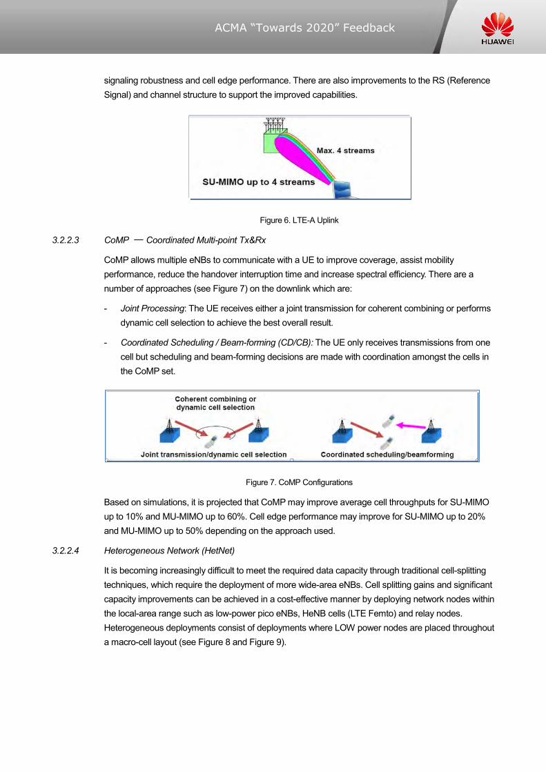
3.2.2.3 CoMP ─ Coordinated Multi-point Tx&Rx
CoMP allows multiple eNBs to communicate with a UE to improve coverage, assist mobility performance, reduce the handover interruption time and increase spectral efficiency. There are a number of approaches (see Figure 7) on the downlink which are:
- Joint Processing: The UE receives either a joint transmission for coherent combining or performs dynamic cell selection to achieve the best overall result.
- Coordinated Scheduling / Beam-forming (CD/CB): The UE only receives transmissions from one cell but scheduling and beam-forming decisions are made with coordination amongst the cells in the CoMP set.
Figure 7. CoMP Configurations
Based on simulations, it is projected that CoMP may improve average cell throughputs for SU-MIMO up to 10% and MU-MIMO up to 60%. Cell edge performance may improve for SU-MIMO up to 20% and MU-MIMO up to 50% depending on the approach used.
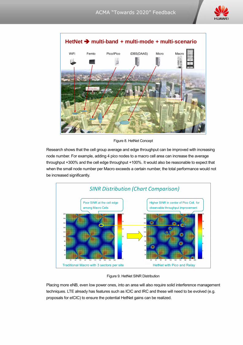
3.2.2.4 Heterogeneous Network (HetNet)
It is becoming increasingly difficult to meet the required data capacity through traditional cell-splitting techniques, which require the deployment of more wide-area eNBs. Cell splitting gains and significant capacity improvements can be achieved in a cost-effective manner by deploying network nodes within the local-area range such as low-power pico eNBs, HeNB cells (LTE Femto) and relay nodes. Heterogeneous deployments consist of deployments where LOW power nodes are placed throughout a macro-cell layout (see Figure 8 and Figure 9).
ACMA “Towards 2020” Feedback
Figure 8. HetNet Concept
Research shows that the cell group average and edge throughput can be improved with increasing node number. For example, adding 4 pico nodes to a macro cell area can increase the average throughput +300% and the cell edge throughput +100%. It would also be reasonable to expect that when the small node number per Macro exceeds a certain number, the total performance would not be increased significantly.
Figure 9. HetNet SINR Distribution
Placing more eNB, even low power ones, into an area will also require solid interference management techniques. LTE already has features such as ICIC and IRC and these will need to be evolved (e.g. proposals for eICIC) to ensure the potential HetNet gains can be realized.
HetNet multi-band + multi-mode + multi-scenario
WiFi Femto Pico/iPico iDBS(DAAS) Micro Macro
SINR Distribution (Chart Comparison)
Traditional Macro with 3 sectors per site HetNet with Pico and Relay
Poor SINR at the cell edge
among Macro Cells
Higher SINR in center of Pico Cell, for
observable throughput improvement

ACMA “Towards 2020” Feedback
Lastly, while HetNet provides a significant technical step forward, it has to be remembered that deploying a large number of small eNB still represents a cost and logistical challenge for operators. Accordingly, more spectrum will be required to balance against the costs of deploying a more dense eNB grid.
3.2.2.5 Relay
As has been noted earlier in this paper, spectrum is driven by the average spectral efficiency not the peak and there is a large difference between the two. As new spectrum becomes more scarce the average spectral efficiency can be improved by bringing the eNB closer to the user affording them improved SINR and higher modulation and MIMO rates. Relay Nodes (RN) have been introduced to enable traffic and signaling forwarding between the eNB and UE to improve the coverage of high data ranges, group mobility, cell edge coverage and to extend the coverage as depicted in Figure 10. Relay nodes are wirelessly connected to the radio access network via a donor cell. Backhaul and access links can use the same carrier (in band) or different carrier (out band). Release 10 provides for a Type1 RN where the relay is in band and the RN appears as a distinct cell from the donor.
Figure 10. Relay Configuration
3.3 TDD versus FDD
In absolute terms the spectral efficiency of TD-LTE is slightly lower than that of LTE-FDD, because of the GP (Guard Period) existence in the frames of TD-LTE that can‟t be used for data transmission. In practical terms TDD offers the opportunity to balance the traffic difference between downlink and uplink and achieve improved spectral efficiency where as FDD is fixed and the uplink may not be as fully used as the downlink.
TDD also offers the opportunity to deploy phased array type beam forming which can increase the average throughputs and capacity of the cell and particularly improve the performance for cell edge users.
From a spectrum management perspective, TDD needs particular attention. For an FDD system, the out of band performance can be defined and is then essentially fixed. For TDD systems, users can change the DL/UL ratio. If neighboring users use the same TDD ratio then less guard band is required. If they use different TDD ratios then more guard band is required. So the need for guard bands versus the advantages of ratio adjustment versus overall spectral efficiency need to be considered.
Backhaul Link
Access Link
Direct link
Donor eNB
Relay

ACMA “Towards 2020” Feedback
4 Long Term Technology Innovations (2020)
It is evident that MBB data traffic will continue to grow rapidly due to the rise of social media, user generated content, the pull effect of ubiquitous broadband, the virtual economy and video + hi-def video and 3D in to the future. Additionally, more things will become wirelessly connected and drive data higher: computers, mobiles, vehicles, industrial components, logistics support, consumer goods and buildings. Analysis of this leads Huawei to postulate that we will need wireless networks that are 20 times faster by 2020. This is a significant challenge and many of the answers are yet to be found but as Alan Kay the inventor of object oriented code said in 1971:
“The best way to predict the future is to invent it”
This is exactly why Huawei is investing in with the industry‟s largest R&D capability both in China and around the globe and is a major contributor to global standards.
When considering how mobile technology needs to evolve in 2020 and beyond, it‟s not just meeting the capacity requirements that are important but also the user experience and the energy consumed. Referring to Figure 11, we can see that today‟s MBB user experience is inconsistent.
Figure 11. Inconsistent User Experience
The second factor is the cost of new sites (CAPEX) and the energy that they consume (OPEX). For example, doubling the carrier frequency in an environment that has a path loss exponent of 3, results in a 9 dB higher propagation loss (1/8 of the power).The cell radius shrinks to 50 %, the cell area shrinks by 25 %, and 300 % more base stations are required to cover a given area. This results in a three times higher investment for operators as well as more energy consumption. To achieve a 20X throughput break through spectrum, new topologies and new air interface techniques will all be required as shown in Figure 12.
Peak user bit rate P
Average user data rate A
Cell edge user data rate E
P/A= 5
A/E= 4
P/E= 20
Industry delivered network with
End User Experience
Inconsistent user experience across the network
ACMA “Towards 2020” Feedback
Figure 12. Future Improvement Areas
There are many concepts being considered for the 2020 mobile network evolution including:
- White Space / Spectrum Agile / Cognitive Radio / which might unleash up to 0.5GHz of spectrum through spectrum agile radios.
- Green Radio. Improving power efficiency and using user created distributed network as an addition to the macro network.
- New networking topologies: including basic scaling, relay scaling and hierarchical MIMO
- Air Interface Improvements: Multi-user collaborative transmission, unified PHY/MAC for heterogeneous networking, Improved interference mitigation
- Caching closer to the eNB and redesigning protocols to exploit this.
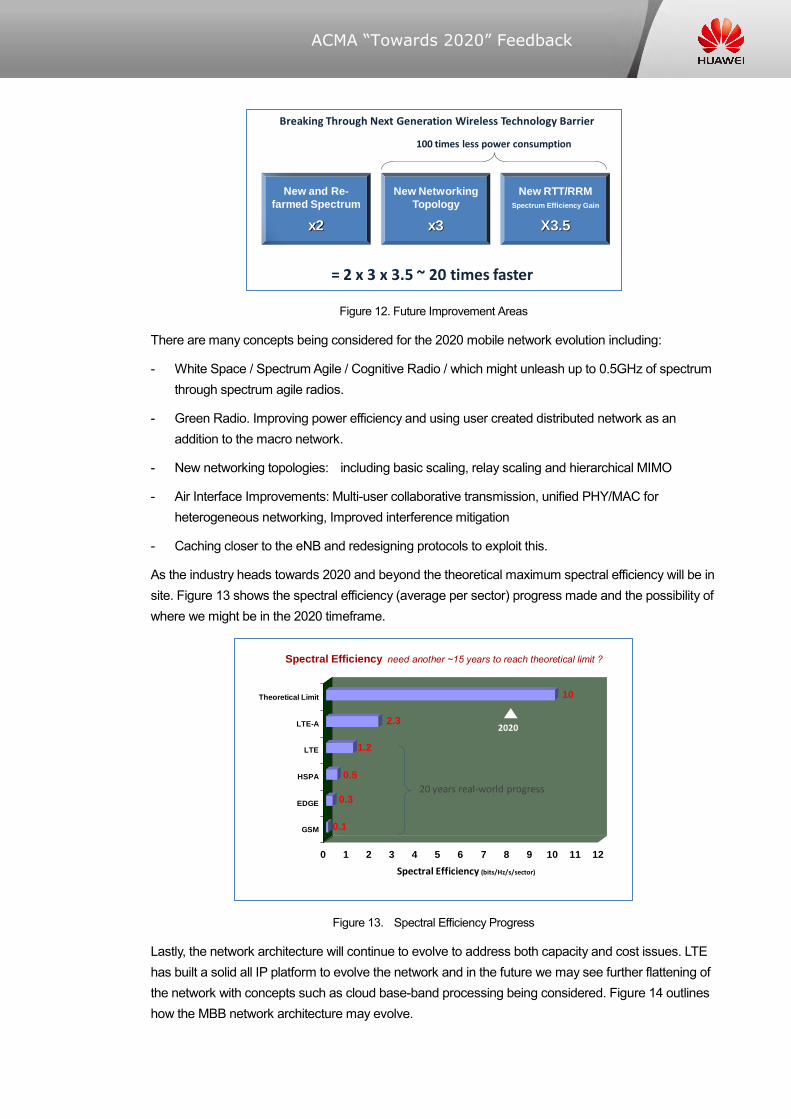
As the industry heads towards 2020 and beyond the theoretical maximum spectral efficiency will be in site. Figure 13 shows the spectral efficiency (average per sector) progress made and the possibility of where we might be in the 2020 timeframe.
Figure 13. Spectral Efficiency Progress
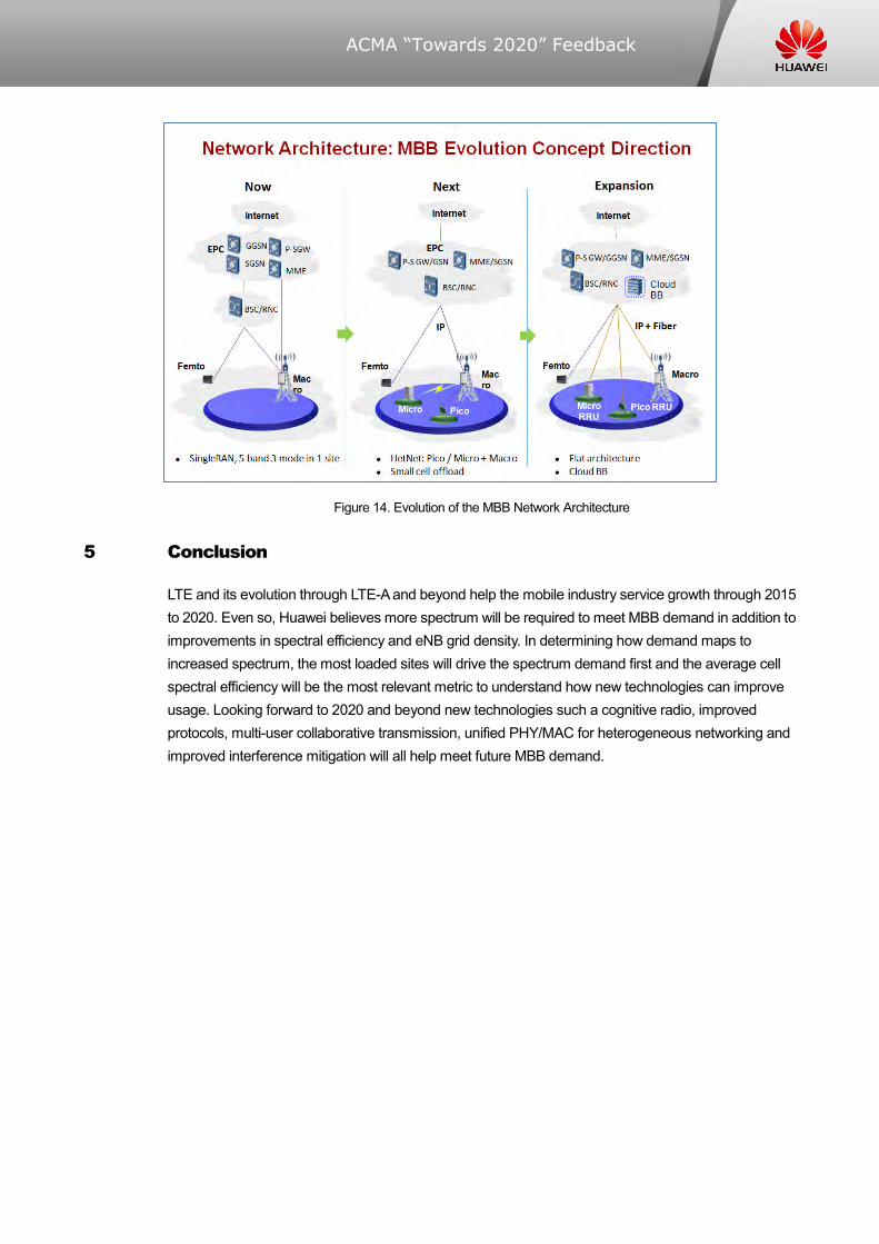
Lastly, the network architecture will continue to evolve to address both capacity and cost issues. LTE has built a solid all IP platform to evolve the network and in the future we may see further flattening of the network with concepts such as cloud base-band processing being considered. Figure 14 outlines how the MBB network architecture may evolve.
New and Re-
farmed Spectrum
x2
New Networking
Topology
x3
New RTT/RRM
Spectrum Efficiency Gain
X3.5
= 2 x 3 x 3.5 ~ 20 times faster
Breaking Through Next Generation Wireless Technology Barrier
100 times less power consumption
Spectral Efficiency need another ~15 years to reach theoretical limit ?
0.1
0.3
0.5
1.2
2.3
10
0 1 2 3 4 5 6 7 8 9 10 11 12
GSM
EDGE
HSPA
LTE
LTE-A
Theoretical Limit
Spectral Efficiency (bits/Hz/s/sector)
20 years real-world progress
2020
ACMA “Towards 2020” Feedback
Figure 14. Evolution of the MBB Network Architecture
5 Conclusion
LTE and its evolution through LTE-A and beyond help the mobile industry service growth through 2015 to 2020. Even so, Huawei believes more spectrum will be required to meet MBB demand in addition to improvements in spectral efficiency and eNB grid density. In determining how demand maps to increased spectrum, the most loaded sites will drive the spectrum demand first and the average cell spectral efficiency will be the most relevant metric to understand how new technologies can improve usage. Looking forward to 2020 and beyond new technologies such a cognitive radio, improved protocols, multi-user collaborative transmission, unified PHY/MAC for heterogeneous networking and improved interference mitigation will all help meet future MBB demand.