huck blind fasteners - fsirivet.com · fastener identification anatomy of huck-clinch
TRANSCRIPT

1
PageHole Preparation .............. 2HuckMAXTM ....................... 3Huck-Clinch® ...................... 8 NAS1919/1921 ………….. 13 MS90353/90354 ................ 19MS21140/21141 ………... 19Ti-Matic® ………………. 24Blind Head Shapes …….. 29Removal ………………... 33Trouble Shooting ……..… 37
5th Edition
Huck Blind Fasteners
PROCESS MANUAL
2
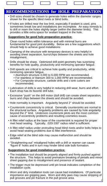
RECOMMENDATIONS for HOLE PREPARATIONRECOMMENDATIONS for HOLE PREPARATION• Drill sizes should be chosen to generate holes within the diameter ranges
shown for the specific blind rivets or blind bolts.• If holes are drilled near the low limit, especially if sealant is used, pins
sometimes break low and installations are incomplete. An easy remedy is to drill or ream the holes slightly larger (within the diameter limits). This provides a little extra space for sealant trapped in the hole.
Suggestions for good hole preparation practice:Clean round holes within tolerance and with minimal burrs are fundamental for good joint durability. Below are a few suggestions which should help to achieve good installations:
• Clamping of the structure with temporary devices is very helpful in avoiding sheet separation, burrs/chips between the sheets and hole misalignment.
• Drills should be sharp. Optimized drill point geometry has surprising benefits for hole quality, productivity and minimizing operator fatigue.
• Drill speeds are critical to achieve hole quality and productivity, while minimizing operator fatigue.
• Aluminum structure 4,000 to 6,000 RPM are recommended. • For stainless or titanium 300 to 1,000 RPM are recommended.• For Composite structure, carbide drills and c’sink cutters are
recommended.• Lubrication of drills is very helpful in reducing drill wear, burrs and effort.
Each shop has its favorite drill lube.• Excessive “push” on the drill motor (dull drill) can create sheet separation,
burrs and chips between the sheets and should be avoided.• Hole normality is important. Angularity beyond 2° should be avoided.• Countersink concentricity is critical. Generally countersinks are normal to
the structural surface. Angularity problems are caused by hole angularity beyond the 2° limit. Undersize countersink pilots are the most common cause of eccentricity problems and resulting cosmetics issues.
• A fillet relief radius at the base of the countersink is required for proper rivet head seating. Typically, .020/.030” radius relief is sufficient.
• A fillet relief radius under protruding head blind rivets and/or bolts helps to avoid head seating problems due to fillet interference.
• Edge relief at the blind side may cause malfunction and should be avoided.
• “Straightening-out” misaligned holes with a drill or reamer can cause “figure 8” holes and in turn may hinder blind side bulb formation.
Suggestions for good installation practice:• The installation tool should be properly aligned and firmly pushed against
the structure. This helps to avoid premature breaking of pintails and minor sheet gapping due to misalignment and presence of sealant.
• The trigger must be depressed until pin break indicates completion of the installation cycle.
• Worn and dirty installation tools can cause bad installations. Of particular importance are gripping jaws. Worn and dirty jaws may cause stripping of pull grooves and pin fracture in the pull groove area.
3
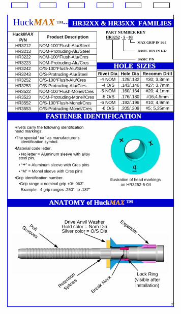
Rivets carry the following identification head markings:•The special “ ” as manufacturer’s
identification symbol.•Material code letter.
• No letter = Aluminum sleeve with alloy steel pin.
• “+” = Aluminum sleeve with Cres pins• “M” = Monel sleeve with Cres pins
•Grip identification number. •Grip range = nominal grip +0/-.063”.Example: -4 grip ranges .250” to .187”
Rivet Dia Hole Dia Recomm Drill-4 NOM .129/.132 #30; 3,3mm-4 O/S .143/.146 #27; 3,7mm
-5 NOM .160/.164 #20; 4,1mm-5 O/S .176/.180 #16;4,5mm
-6 NOM .192/.196 #10; 4,9mm-6 O/S .205/.209 #5; 5,25mm
PART NUMBER KEYHR3252 - 5 - 03
MAX GRIP IN 1/16
BASIC DIA IN 1/32
BASIC P/N
HuckMAX P/N Product Description
HR3212 NOM-100°Flush-Alu/SteelHR3213 NOM-Protruding-Alu/SteelHR3222 NOM-100°Flush-Alu/CresHR3223 NOM-Protruding-Alu/CresHR3242 O/S-100°Flush-Alu/SteelHR3243 O/S-Protruding-Alu/SteelHR3252 O/S-100°Flush-Alu/CresHR3253 O/S-Protruding-Alu/CresHR3522 NOM-100°Flush-Monel/CresHR3523 NOM-Protruding-Monel/CresHR3552 O/S-100°Flush-Monel/CresHR3553 O/S-Protruding-Monel/Cres
HuckMAX ™----HR32XX & HR35XX FAMILIESHR32XX & HR35XX FAMILIES
HOLE SIZESHOLE SIZES
Illustration of head markingson HR3252-5-04
FASTENER IDENTIFICATIONFASTENER IDENTIFICATION
ANATOMY of HuckANATOMY of HuckMAXMAX ™™
Retention
Splines
Expander
Break Neck
Drive Anvil WasherGold color = Nom DiaSilver color = O/S Dia
Pull Grooves
Lock Ring (visible after installation)
4
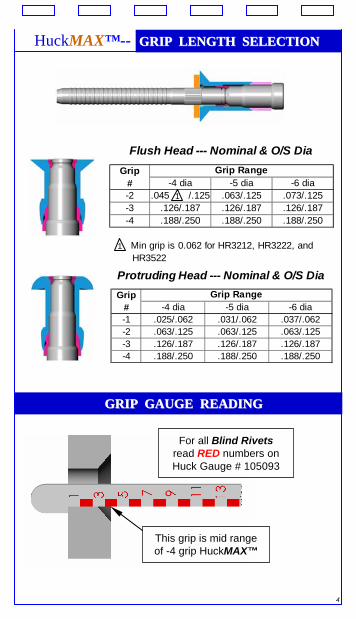
HuckMAX™-- GRIP LENGTH SELECTIONGRIP LENGTH SELECTION
Grip# -4 dia -5 dia -6 dia-1 .025/.062 .031/.062 .037/.062-2 .063/.125 .063/.125 .063/.125-3 .126/.187 .126/.187 .126/.187-4 .188/.250 .188/.250 .188/.250
Grip Range
Protruding Head --- Nominal & O/S Dia
Grip# -4 dia -5 dia -6 dia-2 .045 1 /.125 .063/.125 .073/.125-3 .126/.187 .126/.187 .126/.187-4 .188/.250 .188/.250 .188/.250
1 Min grip is 0.062 for HR3212, HR3222, and HR3522
Grip Range
Flush Head --- Nominal & O/S Dia
GRIP GAUGE READING GRIP GAUGE READING
This grip is mid range of -4 grip HuckMAX™
For all Blind Rivetsread RED numbers onHuck Gauge # 105093
5
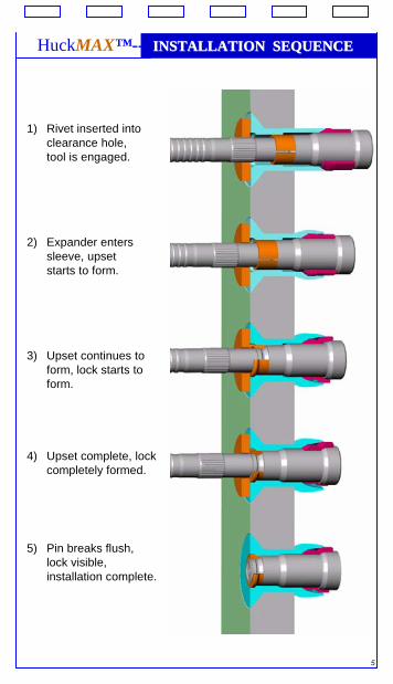
HuckMAX™-- INSTALLATION SEQUENCEINSTALLATION SEQUENCE
1) Rivet inserted into clearance hole, tool is engaged.
2) Expander enters sleeve, upset starts to form.
3) Upset continues to form, lock starts to form.
4) Upset complete, lock completely formed.
5) Pin breaks flush, lock visible,installation complete.
6
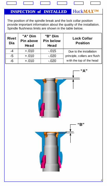
INSPECTION of INSTALLEDINSPECTION of INSTALLED HuckMAX™
The position of the spindle break and the lock collar position provide important information about the quality of the installation. Spindle flushness limits are shown in the table below.
Rivet Dia
"A" Dim Pin above
Head
"B" Dim Pin below
Head
Lock Collar Position
-4 +.010 -.015 Due to the installation-5 +.010 -.020 principle, collars are f lush
-6 +.010 -.020 w ith the top of the head
“A”
“B”
7
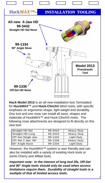
INSTALLATION TOOLINGINSTALLATION TOOLINGHuckMAX™--
Huck Model 2013 is an all new installation tool, formulated for HuckMAX™ and Huck-Clinch® blind rivets, with specific emphasis on ergonomic shape, light weight and durability. One tool and one nose can install all sizes, shapes and materials of HuckMAX™ and Huck-Clinch® rivets. The following nose attachments are designed to fit directly on this new tool:
However, the HuckMAX™ system is user friendly and can also be installed with a variety of existing Huck tools or some Cherry and Allfast tools.
Important note: In the interest of long tool life, Off-Set and 90° Angle tools should only be used when access limitations require them. Durability of straight tools is a multiple of that of limited access tools.
Straight HD Std 99-3442 Heavy DutyStraight-HD Long 99-3443 Heavy DutyOff -Set Single Jaw 99-1333 Light DutyOff -Set 2 Jaw HD 99-1336 Heavy Duty90° Angle Nose 99-1334 Light Duty
Model 2013Pneudraulic
Tool
All new 4-Jaw HD 99-3442
Straight HD Std Nose
99-133490° Angle Nose
99-1336Off-Set HD Nose
8
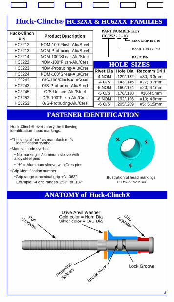
Rivet Dia Hole Dia Recomm Drill-4 NOM .129/.132 #30; 3,3mm-4 O/S .143/.146 #27; 3,7mm
-5 NOM .160/.164 #20; 4,1mm-5 O/S .176/.180 #16;4,5mm
-6 NOM .192/.196 #10; 4,9mm-6 O/S .205/.209 #5; 5,25mm
PART NUMBER KEYHC3252 - 5 - 03
MAX GRIP IN 1/16
BASIC DIA IN 1/32
BASIC P/N
Huck-Clinch P/N Product Description
HC3212 NOM-100°Flush-Alu/SteelHC3213 NOM-Protruding-Alu/SteelHC3214 NOM-100°Shear-Alu/SteelHC6222 NOM-100°Flush-Alu/CresHC6223 NOM-Protruding-Alu/CresHC6224 NOM-100°Shear-Alu/CresHC3242 O/S-100°Flush-Alu/SteelHC3243 O/S-Protruding-Alu/SteelHC3245 O/S-Unisink-Alu/SteelHC6252 O/S-100°Flush-Alu/CresHC6253 O/S-Protruding-Alu/Cres
Huck-Clinch® HC32XX & HC62XX FAMILIESHC32XX & HC62XX FAMILIES
HOLE SIZESHOLE SIZES
Illustration of head markingson HC3252-5-04
Huck-Clinch® rivets carry the following identification head markings:
•The special “ ” as manufacturer’s identification symbol.
•Material code symbol.• No marking = Aluminum sleeve with alloy steel pins
• “+” = Aluminum sleeve with Cres pins•Grip identification number.
•Grip range = nominal grip +0/-.063”.Example: -4 grip ranges .250” to .187”
FASTENER IDENTIFICATIONFASTENER IDENTIFICATION
ANATOMY of HuckANATOMY of Huck--ClinchClinch®®
Retention
Splines
Grip Adjuster
Break Neck
Pull Grooves
Lock Groove
Drive Anvil WasherGold color = Nom DiaSilver color = O/S Dia
9
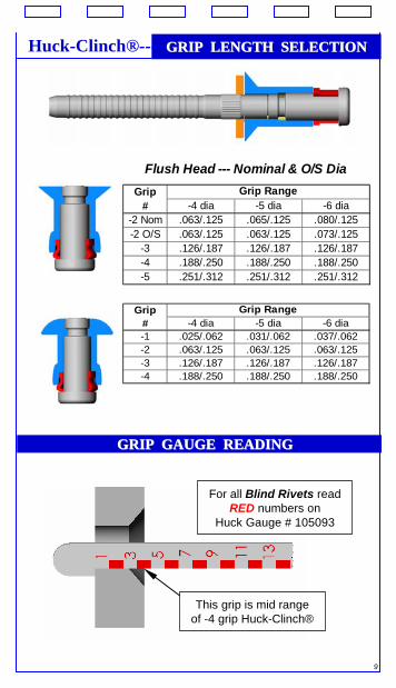
Huck-Clinch®--- GRIP LENGTH SELECTIONGRIP LENGTH SELECTION
Grip# -4 dia -5 dia -6 dia
-2 Nom .063/.125 .065/.125 .080/.125-2 O/S .063/.125 .063/.125 .073/.125
-3 .126/.187 .126/.187 .126/.187-4 .188/.250 .188/.250 .188/.250-5 .251/.312 .251/.312 .251/.312
Grip Range
Flush Head --- Nominal & O/S Dia
Grip# -4 dia -5 dia -6 dia-1 .025/.062 .031/.062 .037/.062-2 .063/.125 .063/.125 .063/.125-3 .126/.187 .126/.187 .126/.187-4 .188/.250 .188/.250 .188/.250
Grip Range
GRIP GAUGE READING GRIP GAUGE READING
This grip is mid range of -4 grip Huck-Clinch®
For all Blind Rivets read RED numbers on
Huck Gauge # 105093
10
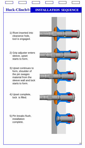
1) Rivet inserted into clearance hole, tool is engaged.
2) Grip adjuster enters sleeve, upset starts to form.
3) Upset continues to form, shoulder of the pin swages material from the sleeve wall and lock starts to form.
4) Upset complete, lock is filled.
5) Pin breaks flush, installation complete.
Huck-Clinch®--- INSTALLATION SEQUENCEINSTALLATION SEQUENCE

11
INSPECTION of INSTALLEDINSPECTION of INSTALLED ----Huck-Clinch®
The position of the spindle break and the lock collar position provide important information about the quality of the installation. Spindle flushness limits are shown in the table below.
Rivet Dia
"A" Dimension Pin above
Head
"B" Dimension Pin below
Head
Internal "Solid Circle" Lock
-4 +.010 -.015
-5 +.010 -.020
-6 +.010 -.020
No Lock Ring is visible at the rivet head. Spindle
Flushness indicates Proper Lock Formation
“A” “B”
HEAD SHAVINGThe head of flush tension Huck-Clinch® blind rivets can beshaved for cosmetic or aerodynamic improvement if:
1) Spindle flushness meets the limits of table above prior to shaving.and
2) The recommended shave limits of table below are not exceeded.
Shaving of shear head Huck-Clinch® blind rivets (e.g. HC3214, HC6224 ) is not recommended.
Rivet Diameter
Max Recommended Head Shave
-4 0.006”-5 0.008”-6 0.010”
12
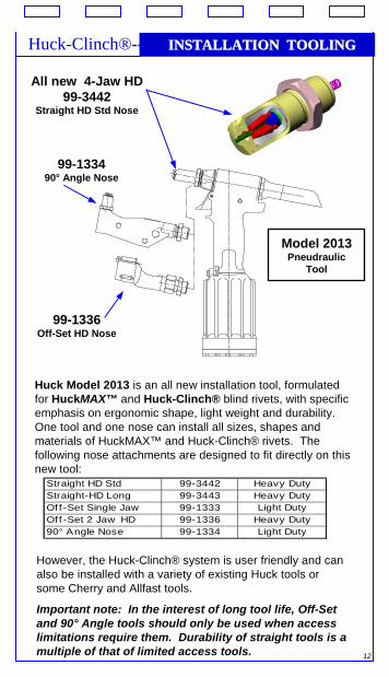
INSTALLATION TOOLINGINSTALLATION TOOLINGHuck-Clinch®---
Huck Model 2013 is an all new installation tool, formulated for HuckMAX™ and Huck-Clinch® blind rivets, with specific emphasis on ergonomic shape, light weight and durability. One tool and one nose can install all sizes, shapes and materials of HuckMAX™ and Huck-Clinch® rivets. The following nose attachments are designed to fit directly on this new tool:
Straight HD Std 99-3442 Heavy DutyStraight-HD Long 99-3443 Heavy DutyOff -Set Single Jaw 99-1333 Light DutyOff -Set 2 Jaw HD 99-1336 Heavy Duty90° Angle Nose 99-1334 Light Duty
Model 2013Pneudraulic
Tool
All new 4-Jaw HD 99-3442
Straight HD Std Nose
99-133490° Angle Nose
99-1336Off-Set HD Nose
However, the Huck-Clinch® system is user friendly and can also be installed with a variety of existing Huck tools or some Cherry and Allfast tools.
Important note: In the interest of long tool life, Off-Set and 90° Angle tools should only be used when access limitations require them. Durability of straight tools is a multiple of that of limited access tools.
13
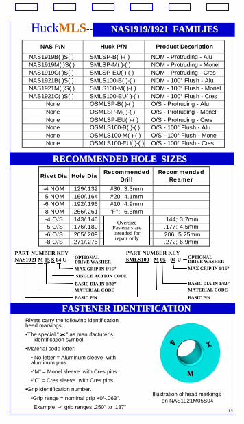
HuckMLS--------NAS1919/1921 FAMILIESNAS1919/1921 FAMILIES
RECOMMENDED HOLE SIZESRECOMMENDED HOLE SIZES
Illustration of head markingson NAS1921M05S04
Rivets carry the following identification head markings:•The special “ ” as manufacturer’s
identification symbol.•Material code letter:
• No letter = Aluminum sleeve with aluminum pins•“M” = Monel sleeve with Cres pins•“C” = Cres sleeve with Cres pins
•Grip identification number. •Grip range = nominal grip +0/-.063”.Example: -4 grip ranges .250” to .187”
FASTENER IDENTIFICATIONFASTENER IDENTIFICATION
NAS P/N Huck P/N Product Description
NAS1919B( )S( ) SMLSP-B( )-( ) NOM - Protruding - AluNAS1919M( )S( ) SMLSP-M( )-( ) NOM - Protruding - MonelNAS1919C( )S( ) SMLSP-EU( )-( ) NOM - Protruding - CresNAS1921B( )S( ) SMLS100-B( )-( ) NOM - 100° Flush - AluNAS1921M( )S( ) SMLS100-M( )-( ) NOM - 100° Flush - MonelNAS1921C( )S( ) SMLS100-EU( )-( ) NOM - 100° Flush - Cres
None OSMLSP-B( )-( ) O/S - Protruding - AluNone OSMLSP-M( )-( ) O/S - Protruding - MonelNone OSMLSP-EU( )-( ) O/S - Protruding - CresNone OSMLS100-B( )-( ) O/S - 100° Flush - AluNone OSMLS100-M( )-( ) O/S - 100° Flush - MonelNone OSMLS100-EU( )-( ) O/S - 100° Flush - Cres
Rivet Dia Hole Dia Recommended Drill
Recommended Reamer
-4 NOM .129/.132 #30; 3.3mm-5 NOM .160/.164 #20; 4.1mm-6 NOM .192/.196 #10; 4.9mm-8 NOM .256/.261 "F"; 6.5mm-4 O/S .143/.146 .144; 3.7mm-5 O/S .176/.180 .177; 4.5mm-6 O/S .205/.209 .206; 5.25mm-8 O/S .271/.275 .272; 6.9mm
Oversize Fasteners are intended for repair only
M
4
PART NUMBER KEYNAS1921 M 05 S 04 U
SINGLE ACTION CODEMAX GRIP IN 1/16”
BASIC DIA IN 1/32”
BASIC P/NMATERIAL CODE
OPTIONAL DRIVE WASHER
PART NUMBER KEYSMLS100 - M 05 - 04 U
MAX GRIP IN 1/16”
BASIC DIA IN 1/32”MATERIAL CODE
OPTIONAL DRIVE WASHER
BASIC P/N
14
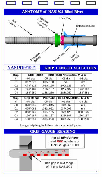
ANATOMY of NAS1921 Blind Rivet ANATOMY of NAS1921 Blind Rivet
Retention
SplinesBreak N
eck
Optional Drive Anvil Washer
Pull Grooves
Lock Ring
Lock
Groove
Expansion Land
Grip# -04 dia -05 dia -06 dia -08 dia
-00 .020/.035 .025/.045 .037/.062 n/a-01 .025/.062 .031/.062 .037/.062 n/a-02 .063/.125 .063/.125 .063/.125 .063/.125-03 .126/.187 .126/.187 .126/.187 .126/.187-04 .188/.250 .188/.250 .188/.250 .188/.250
Grip Range -- Protruding Head NAS1919B, M & C
Grip# -04 dia -05 dia -06 dia -08 dia
-01 .057/.078 .075/.100 n/a n/a-02 .078/.125 .080/.125 .100/.125 n/a-03 .126/.187 .126/.187 .126/.187 .126/.187-04 .188/.250 .188/.250 .188/.250 .188/.251
Grip Range -- Flush Head NAS1921B, M & C
GRIP GAUGE READING GRIP GAUGE READING
This grip is mid range of -4 grip NAS1921
For all Blind Rivetsread RED numbers onHuck Gauge # 105093
NAS1919/1921---- GRIP LENGTH SELECTIONGRIP LENGTH SELECTION
Longer grip lengths follow this incremental pattern
15
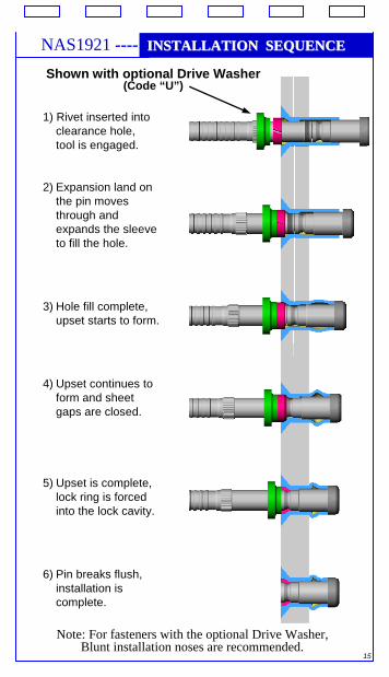
NAS1921 ---- INSTALLATION SEQUENCEINSTALLATION SEQUENCE
1) Rivet inserted into clearance hole, tool is engaged.
2) Expansion land on the pin moves through and expands the sleeve to fill the hole.
3) Hole fill complete, upset starts to form.
4) Upset continues to form and sheet gaps are closed.
5) Upset is complete, lock ring is forced into the lock cavity.
6) Pin breaks flush, installation is complete.
Shown with optional Drive Washer(Code “U”)
Note: For fasteners with the optional Drive Washer,Blunt installation noses are recommended.
16
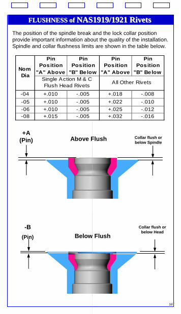
FLUSHNESS of FLUSHNESS of NAS1919/1921 RivetsNAS1919/1921 RivetsThe position of the spindle break and the lock collar position provide important information about the quality of the installation. Spindle and collar flushness limits are shown in the table below.
Pin Position
"A" Above
Pin Position
"B" Below
Pin Position
"A" Above
Pin Position
"B" Below
-04 +.010 -.005 +.018 -.008-05 +.010 -.005 +.022 -.010-06 +.010 -.005 +.025 -.012-08 +.015 -.005 +.032 -.016
Single Action M & C Flush Head Rivets All Other Rivets
Nom Dia
+A (Pin) Collar flush or
below SpindleAbove Flush
Below Flush-B
(Pin)
Collar flush or below Head
17
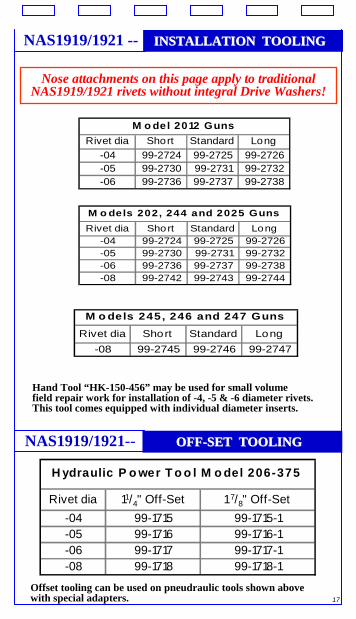
INSTALLATION TOOLINGINSTALLATION TOOLINGNAS1919/1921 --
Nose attachments on this page apply to traditionalNAS1919/1921 rivets without integral Drive Washers!
Rivet dia Short Standard Long-04 99-2724 99-2725 99-2726-05 99-2730 99-2731 99-2732-06 99-2736 99-2737 99-2738
M o del 2012 Guns
Rivet dia Short Standard Long-04 99-2724 99-2725 99-2726-05 99-2730 99-2731 99-2732-06 99-2736 99-2737 99-2738-08 99-2742 99-2743 99-2744
M o dels 202, 244 and 2025 Guns
Rivet dia Short Standard Long-08 99-2745 99-2746 99-2747
M o dels 245, 246 and 247 Guns
Hand Tool “HK-150-456” may be used for small volumefield repair work for installation of -4, -5 & -6 diameter rivets. This tool comes equipped with individual diameter inserts.
OFFOFF--SET TOOLINGSET TOOLINGNAS1919/1921--
Rivet dia 11/4" Off-Set 1 7/8" Off-Set-04 99-1715 99-1715-1-05 99-1716 99-1716-1-06 99-1717 99-1717-1-08 99-1718 99-1718-1
H ydraulic P o wer T o o l M o del 206-375
Offset tooling can be used on pneudraulic tools shown above with special adapters.
18
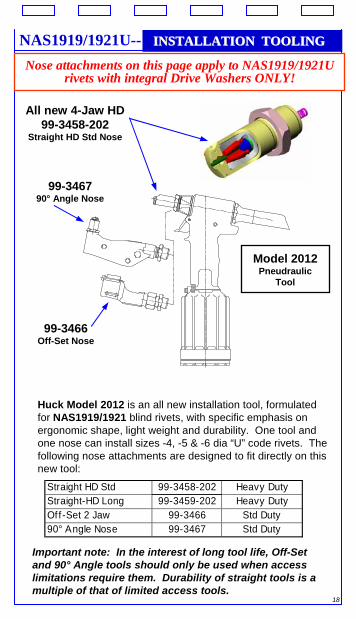
INSTALLATION TOOLINGINSTALLATION TOOLINGNAS1919/1921U--
Model 2012Pneudraulic
Tool
All new 4-Jaw HD 99-3458-202
Straight HD Std Nose
99-346790° Angle Nose
99-3466Off-Set Nose
Nose attachments on this page apply to NAS1919/1921Urivets with integral Drive Washers ONLY!
Huck Model 2012 is an all new installation tool, formulated for NAS1919/1921 blind rivets, with specific emphasis on ergonomic shape, light weight and durability. One tool and one nose can install sizes -4, -5 & -6 dia “U” code rivets. The following nose attachments are designed to fit directly on this new tool:
Straight HD Std 99-3458-202 Heavy DutyStraight-HD Long 99-3459-202 Heavy DutyOf f -Set 2 Jaw 99-3466 Std Duty90° Angle Nose 99-3467 Std Duty
Important note: In the interest of long tool life, Off-Set and 90° Angle tools should only be used when access limitations require them. Durability of straight tools is a multiple of that of limited access tools.
19
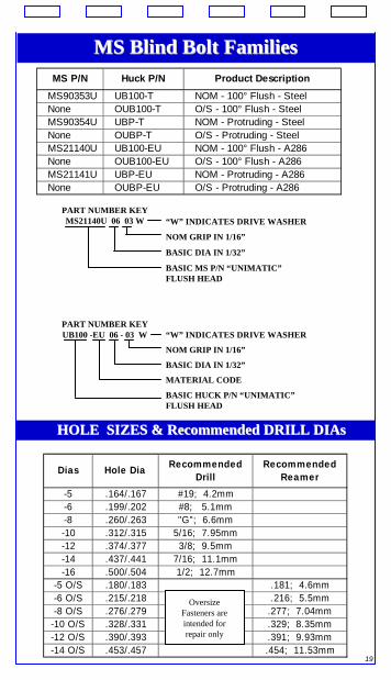
MS Blind Bolt FamiliesMS Blind Bolt FamiliesMS P/N Huck P/N Product Description
MS90353U UB100-T NOM - 100° Flush - SteelNone OUB100-T O/S - 100° Flush - SteelMS90354U UBP-T NOM - Protruding - SteelNone OUBP-T O/S - Protruding - SteelMS21140U UB100-EU NOM - 100° Flush - A286None OUB100-EU O/S - 100° Flush - A286MS21141U UBP-EU NOM - Protruding - A286None OUBP-EU O/S - Protruding - A286
PART NUMBER KEYMS21140U 06 03 W
BASIC MS P/N “UNIMATIC”FLUSH HEAD
BASIC DIA IN 1/32”
NOM GRIP IN 1/16”
“W” INDICATES DRIVE WASHER
PART NUMBER KEYUB100 -EU 06 - 03 W
BASIC HUCK P/N “UNIMATIC”FLUSH HEAD
BASIC DIA IN 1/32”
NOM GRIP IN 1/16”
“W” INDICATES DRIVE WASHER
MATERIAL CODE
HOLE SIZES & Recommended DRILL HOLE SIZES & Recommended DRILL DIAsDIAs
Dias Hole Dia Recommended Drill
Recommended Reamer
-5 .164/.167 #19; 4.2mm-6 .199/.202 #8; 5.1mm-8 .260/.263 "G"; 6.6mm-10 .312/.315 5/16; 7.95mm-12 .374/.377 3/8; 9.5mm-14 .437/.441 7/16; 11.1mm-16 .500/.504 1/2; 12.7mm
-5 O/S .180/.183 .181; 4.6mm-6 O/S .215/.218 .216; 5.5mm-8 O/S .276/.279 .277; 7.04mm
-10 O/S .328/.331 .329; 8.35mm-12 O/S .390/.393 .391; 9.93mm-14 O/S .453/.457 .454; 11.53mm
Oversize Fasteners are intended for repair only
20
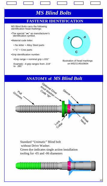
FASTENER IDENTIFICATION
Illustration of head markingson MS21140U0604
MS Blind Bolts carry the following identification head markings:
•The special “ ” as manufacturer’s identification symbol.
•Material code letter.
• No letter = Alloy Steel parts
• “C” = Cres parts
•Grip identification number.
•Grip range = nominal grip ±.031”
Example: -4 grip ranges from .219”to .281”
MS Blind Bolts
C
ANATOMY of MS Blind Bolt
Sleeve
Optional Drive
Anvil Washer
Code “W”
Pull Grooves
Lock
Collar
BreakNeck
Standard “Unimatic” Blind boltwithout Drive Washer. Green dye indicates single action installation tooling for -05 and -06 diameters
21
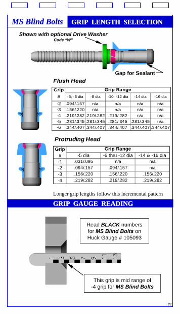
Protruding HeadGrip
# -5 dia -6 thru -12 dia -14 & -16 dia-1 .031/.095 n/a n/a-2 .094/.157 .094/.157 n/a-3 .156/.220 .156/.220 .156/.220-4 .219/.282 .219/.282 .219/.282
Grip Range
Flush HeadGrip
# -5; -6 dia -8 dia -10; -12 dia -14 dia -16 dia
-2 .094/.157 n/a n/a n/a n/a-3 .156/.220 n/a n/a n/a n/a-4 .219/.282 .219/.282 .219/.282 n/a n/a-5 .281/.345 .281/.345 .281/.345 .281/.345 n/a-6 .344/.407 .344/.407 .344/.407 .344/.407 .344/.407
Grip Range
Shown with optional Drive WasherCode “W”
Gap for Sealant
MS Blind BoltsMS Blind Bolts GRIP LENGTH SELECTIONGRIP LENGTH SELECTION
Longer grip lengths follow this incremental pattern
GRIP GAUGE READING GRIP GAUGE READING
This grip is mid range of -4 grip for MS Blind Bolts
Read BLACK numbers for MS Blind Bolts onHuck Gauge # 105093
22
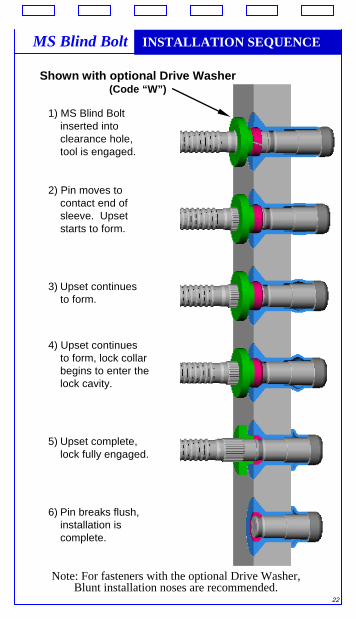
MS Blind Bolt INSTALLATION SEQUENCE
Shown with optional Drive Washer(Code “W”)
1) MS Blind Bolt inserted into clearance hole, tool is engaged.
2) Pin moves to contact end of sleeve. Upset starts to f
orm.
3) Upset continues to form.
4) Upset continues to form, lock collar begins to enter the lock cavity.
5) Upset complete, lock fully engaged.
6) Pin breaks flush, installation is complete.
Note: For fasteners with the optional Drive Washer,Blunt installation noses are recommended.
23
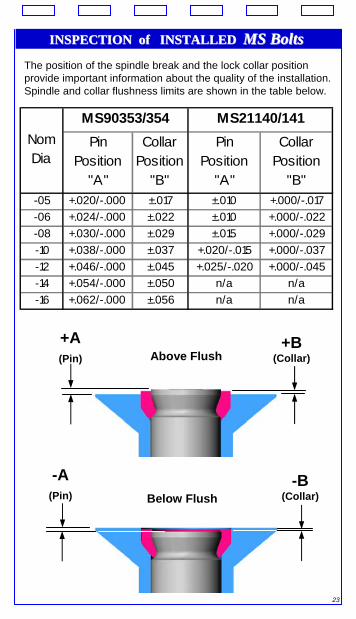
INSPECTION of INSTALLED INSPECTION of INSTALLED MS BoltsMS BoltsThe position of the spindle break and the lock collar position provide important information about the quality of the installation. Spindle and collar flushness limits are shown in the table below.
Pin Position
"A"
Collar Position
"B"
Pin Position
"A"
Collar Position
"B"-05 +.020/-.000 ±.017 ±.010 +.000/-.017-06 +.024/-.000 ±.022 ±.010 +.000/-.022-08 +.030/-.000 ±.029 ±.015 +.000/-.029-10 +.038/-.000 ±.037 +.020/-.015 +.000/-.037-12 +.046/-.000 ±.045 +.025/-.020 +.000/-.045-14 +.054/-.000 ±.050 n/a n/a-16 +.062/-.000 ±.056 n/a n/a
MS90353/354 MS21140/141Nom Dia
+A (Pin)
+B (Collar)Above Flush
Below Flush-B
(Collar)
-A (Pin)
24
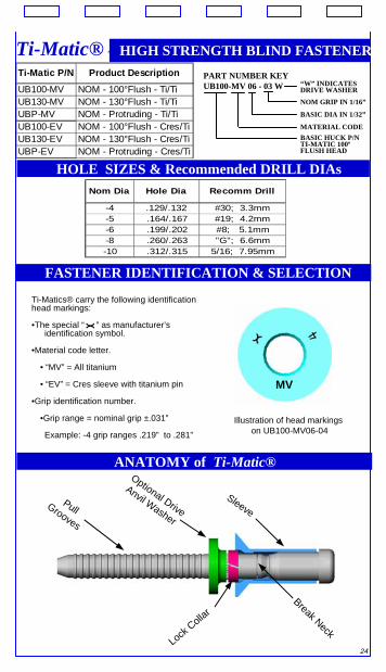
Ti-Matic P/N Product Description
UB100-MV NOM - 100°Flush - Ti/TiUB130-MV NOM - 130°Flush - Ti/TiUBP-MV NOM - Protruding - Ti/TiUB100-EV NOM - 100°Flush - Cres/TiUB130-EV NOM - 130°Flush - Cres/TiUBP-EV NOM - Protruding - Cres/Ti
Nom Dia Hole Dia Recomm Drill
-4 .129/.132 #30; 3.3mm-5 .164/.167 #19; 4.2mm-6 .199/.202 #8; 5.1mm-8 .260/.263 "G"; 6.6mm-10 .312/.315 5/16; 7.95mm
HOLE SIZES & Recommended DRILL DIAs
FASTENER IDENTIFICATION & SELECTION
ANATOMY of Ti-Matic®
Sleeve
Optional Drive
Anvil Washer
Pull Grooves
Lock Collar
Break Neck
Illustration of head markingson UB100-MV06-04
Ti-Matics® carry the following identification head markings:
•The special “ ” as manufacturer’s identification symbol.
•Material code letter.
• “MV” = All titanium
• “EV” = Cres sleeve with titanium pin
•Grip identification number.
•Grip range = nominal grip ±.031”
Example: -4 grip ranges .219” to .281”
MV
Ti-Matic® - HIGH STRENGTH BLIND FASTENERPART NUMBER KEYUB100-MV 06 - 03 W
NOM GRIP IN 1/16”
BASIC DIA IN 1/32”
BASIC HUCK P/NTI-MATIC 100ºFLUSH HEAD
“W” INDICATESDRIVE WASHER
MATERIAL CODE
25
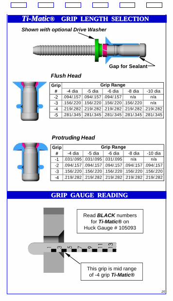
TiTi--MaticMatic®® GRIP LENGTH SELECTIONGRIP LENGTH SELECTION
Protruding HeadGrip
# -4 dia -5 dia -6 dia -8 dia -10 dia-1 .031/.095 .031/.095 .031/.095 n/a n/a-2 .094/.157 .094/.157 .094/.157 .094/.157 .094/.157-3 .156/.220 .156/.220 .156/.220 .156/.220 .156/.220-4 .219/.282 .219/.282 .219/.282 .219/.282 .219/.282
Grip Range
Flush HeadGrip
# -4 dia -5 dia -6 dia -8 dia -10 dia-2 .094/.157 .094/.157 .094/.157 n/a n/a-3 .156/.220 .156/.220 .156/.220 .156/.220 n/a-4 .219/.282 .219/.282 .219/.282 .219/.282 .219/.282-5 .281/.345 .281/.345 .281/.345 .281/.345 .281/.345
Grip Range
Shown with optional Drive Washer
Gap for Sealant
GRIP GAUGE READING GRIP GAUGE READING
This grip is mid range of -4 grip Ti-Matic®
Read BLACK numbers for Ti-Matic® on
Huck Gauge # 105093
26
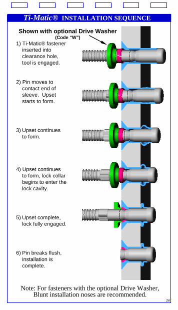
Ti-Matic® INSTALLATION SEQUENCE
Shown with optional Drive Washer(Code “W”)
1) Ti-Matic® fastener inserted into clearance hole, tool is engaged.
2) Pin moves to contact end of sleeve. Upset starts to form.
3) Upset continues to form.
4) Upset continues to form, lock collar begins to enter the lock cavity.
5) Upset complete, lock fully engaged.
6) Pin breaks flush, installation is complete.
Note: For fasteners with the optional Drive Washer,Blunt installation noses are recommended.
27
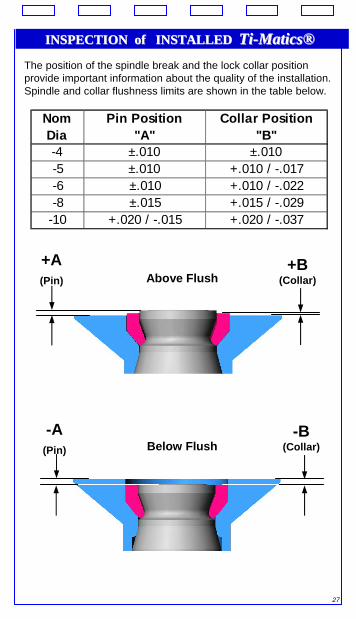
INSPECTION of INSTALLED INSPECTION of INSTALLED TiTi--MaticsMatics®®The position of the spindle break and the lock collar position provide important information about the quality of the installation. Spindle and collar flushness limits are shown in the table below.
Nom Dia
Pin Position "A"
Collar Position "B"
-4 ±.010 ±.010-5 ±.010 +.010 / -.017-6 ±.010 +.010 / -.022-8 ±.015 +.015 / -.029
-10 +.020 / -.015 +.020 / -.037
+A (Pin)
+B (Collar)Above Flush
Below Flush-B
(Collar)-A
(Pin)
28
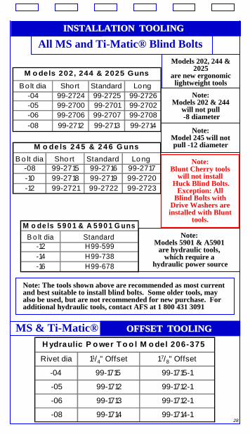
INSTALLATION TOOLINGINSTALLATION TOOLING
All MS and Ti-Matic® Blind Bolts
Bolt dia Short Standard Long-04 99-2724 99-2725 99-2726-05 99-2700 99-2701 99-2702-06 99-2706 99-2707 99-2708-08 99-2712 99-2713 99-2714
M o dels 202, 244 & 2025 Guns
B o lt dia Sho rt Standard Lo ng-08 99-2715 99-2716 99-2717-10 99-2718 99-2719 99-2720-12 99-2721 99-2722 99-2723
M o de ls 2 4 5 & 2 4 6 G uns
Models 202, 244 & 2025
are new ergonomiclightweight tools
M o de ls 5 9 0 1 & A 5 9 0 1 G unsB o lt dia Standard
-12 H99-599-14 H99-738-16 H99-678
Note:Models 5901 & A5901
are hydraulic tools,which require a
hydraulic power source
Note:Models 202 & 244
will not pull-8 diameter
Note: Blunt Cherry tools
will not installHuck Blind Bolts.
Exception: All Blind Bolts with
Drive Washers are installed with Blunt
tools.
Note:Model 245 will not pull -12 diameter
Note: The tools shown above are recommended as most current and best suitable to install blind bolts. Some older tools, mayalso be used, but are not recommended for new purchase. For additional hydraulic tools, contact AFS at 1 800 431 3091
Rivet dia 11/4" Offset 1 7/8" Offset
-04 99-1715 99-1715-1
-05 99-1712 99-1712-1
-06 99-1713 99-1712-1
-08 99-1714 99-1714-1
H ydraulic P o wer T o o l M o del 206-375
OFFSET TOOLINGOFFSET TOOLINGMS & Ti-Matic®
29
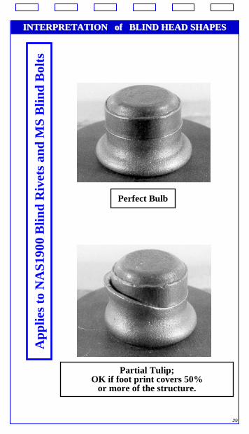
INTERPRETATION of BLIND HEAD SHAPESINTERPRETATION of BLIND HEAD SHAPESA
pplie
s to
NA
S190
0 B
lind
Riv
ets a
nd M
S B
lind
Bol
ts
Perfect Bulb
Partial Tulip;OK if foot print covers 50%
or more of the structure.
30
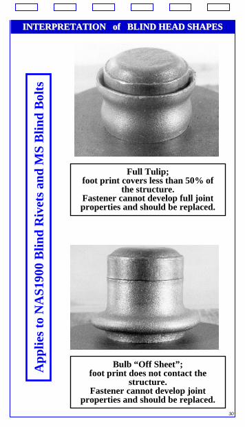
INTERPRETATION of BLIND HEAD SHAPESINTERPRETATION of BLIND HEAD SHAPESA
pplie
s to
NA
S190
0 B
lind
Riv
ets a
nd M
S B
lind
Bol
ts
Full Tulip;foot print covers less than 50% of
the structure.Fastener cannot develop full joint properties and should be replaced.
Bulb “Off Sheet”;foot print does not contact the
structure.Fastener cannot develop joint
properties and should be replaced.
31
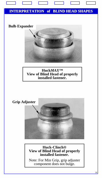
INTERPRETATION of BLIND HEAD SHAPESINTERPRETATION of BLIND HEAD SHAPES
Bulb Expander
HuckMAX™View of Blind Head of properly
installed fastener.
Grip Adjuster
Huck-Clinch®View of Blind Head of properly
installed fastener.Note: For Min Grip, grip adjuster
component does not bulge.
32
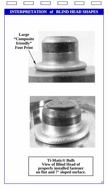
INTERPRETATION of BLIND HEAD SHAPESINTERPRETATION of BLIND HEAD SHAPESINTERPRETATION of BLIND HEAD SHAPESINTERPRETATION of BLIND HEAD SHAPES
Large “Composite
friendly”Foot Print
Ti-Matic® BulbView of Blind Head of
properly installed fasteneron flat and 7° sloped surface.
33
BLIND FASTENER REMOVALBLIND FASTENER REMOVAL
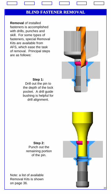
Removal of installed fasteners is accomplished with drills, punches and skill. For some types of fasteners, special Removal Kits are available from AFS, which ease the task of removal. Principal steps are as follows:
Step 1:Drill out the pin to
the depth of the lock pocket. A drill guide bushing is helpful for
drill alignment.
Step 2:Punch out the
remaining portion of the pin.
Note: a list of availableRemoval Kits is shown on page 36.
34
BLIND FASTENER REMOVAL contBLIND FASTENER REMOVAL cont’’dd
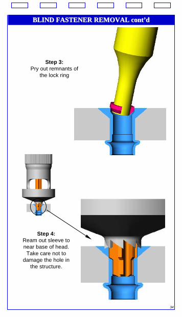
Step 3:Pry out remnants of
the lock ring
Step 4:Ream out sleeve to near base of head.
Take care not to damage the hole in
the structure.
35
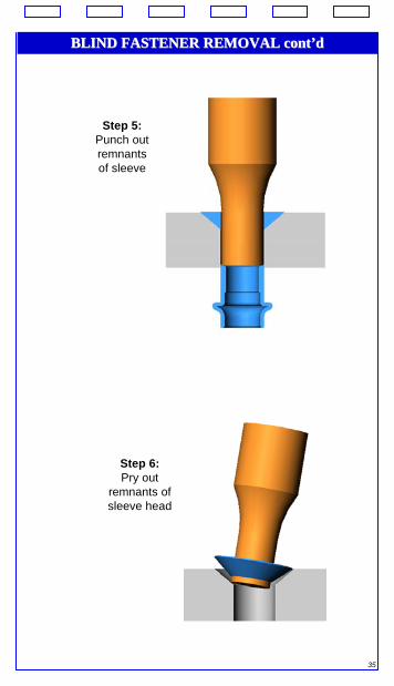
BLIND FASTENER REMOVAL contBLIND FASTENER REMOVAL cont’’dd
Step 5:Punch out remnants of sleeve
Step 6:Pry out
remnants of sleeve head
36
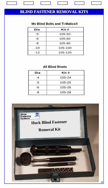
BLIND FASTENER REMOVAL KITSBLIND FASTENER REMOVAL KITS
Ms Blind Bolts and Ti-Matics®
Dia Kit #-5 105-50
-6 105-60
-8 105-80
-10 105-100
-12 105-120
All Blind Rivets
Dia Kit #
-4 105-24
-5 105-25
-6 105-26
-8 105-28
Huck Blind Fastener
Removal Kit
37
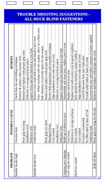
TROUBLE SHOOTING SUGGESTIONSTROUBLE SHOOTING SUGGESTIONS----ALL HUCK BLIND FASTENERSALL HUCK BLIND FASTENERS
PRO
BL
EM
POSS
IBL
E C
AU
SER
EM
ED
YSp
indl
e br
eaks
hig
hO
vers
ize
hole
Che
ck h
ole
dia
and
drill
ing
tech
niqu
eR
emov
e &
repl
ace
with
ove
rsiz
e riv
etR
ivet
grip
too
long
Rem
ove
and
repl
ace
with
pro
per g
rip ri
vet
Inst
alla
tion
tool
Def
ectiv
e or
wro
ng to
ol/n
ose
piec
eD
efec
tive
rivet
Insp
ect r
ivet
s and
test
func
tion
in a
test
hol
eSp
indl
e br
eaks
low
Und
ersiz
e ho
leR
emov
e riv
et, r
eam
hol
e to
size
and
inst
all a
new
rive
tN
ote:
Whe
n w
orki
ng w
ith w
et se
alan
t, al
low
for a
littl
e ex
tra
hole
cle
aran
ce to
pro
vide
spac
e fo
r the
seal
ant
Riv
et g
rip to
o sh
ort
Rem
ove
and
repl
ace
with
pro
per g
rip ri
vet
Misa
ligne
d ho
les
Rev
iew
hol
e pr
epar
atio
n an
d as
sem
bly
tech
niqu
eTo
ol c
ocke
dA
lign
inst
alla
tion
tool
with
axi
s of r
ivet
Inst
alla
tion
tool
Def
ectiv
e or
wro
ng to
ol/n
ose
piec
eD
efec
tive
rivet
Insp
ect r
ivet
s and
test
func
tion
in a
test
hol
eG
rippi
ng ja
ws s
lippi
ngB
uild
-up
of d
ebris
in ja
ws
Disa
ssem
ble
and
clea
n ja
ws;
repl
ace
jaw
s if w
orn
Lock
ring
not
seat
edTo
ol w
orn
Rep
lace
anv
il in
tool
nos
eD
efec
tive
or w
rong
tool
/nos
eR
epla
ce to
ol w
ith c
orre
ct to
ol in
goo
d co
nditi
onH
ead
not s
eate
dH
ole
cock
edH
ole
shou
ld b
e no
rmal
to su
rface
with
in 2
°To
ol c
ocke
dA
lign
inst
alla
tion
tool
with
axi
s of r
ivet
Ecce
ntric
cou
nter
sink
Goo
d fit
bet
wee
n ho
le a
nd c
'sink
pilo
tN
o fil
let r
elie
f at b
ase
of c
'skPr
ovid
e re
lief r
adiu
s at b
ase
of c
'sink
Und
ersiz
e ho
leIn
crea
se h
ole
size
and
redu
ce a
mou
nt o
f sea
lant
app
lied
Bul
b of
f-she
etR
ivet
grip
too
long
for t
he jo
bR
emov
e an
d re
plac
e w
ith p
rope
r siz
e riv
et

38
The purpose of this manual is to provide general guidelines regarding the use of Alcoa Fastening Systems blind fasteners. In the event of conflict between this manual and the user’s company policies, the user should refer to his/her own company’s policies.
For Fastener and Installation Tooling Info,Please visit www.alcoafasteners.com
Huck Blind Fasteners and Installation Tools
are offered through AFS authorized Distributors
Alcoa Fastening Systems
Aerospace ProductsTucson Operations
Tucson, AZ1 800 234 4825
Installation ToolsCommercial ProductsKingston Operations
Kingston, NY 1 800 431 3091
For a list of authorized Distributors, please call
1 800 421 1459Or visit
www.alcoafasteners.com
Alcoa Fastening Systems© Printed in USA 20055th Edition