hughes 9502 fixed satellite terminal · hughes 9502 fixed satellite terminal p/n 3500509-0001 ......
TRANSCRIPT
Hughes 9502 Fixed Satellite Terminal
P/N 3500509-0001
User Guide
Document No. 3004146-0001 Rev H
18-January 2017
Copyright © 2012 - 2017 Hughes Network Systems, LLC
All rights reserved. This publication and its contents are proprietary to Hughes Network Systems, LLC. No part of this publication may be reproduced in any form or by any means without the written permission of Hughes Network Systems, LLC, 11717 Exploration Lane, Germantown, Maryland 20876.
Hughes Network Systems, LLC has made every effort to ensure the correctness and completeness of the material in this document. Hughes Network Systems, LLC shall not be liable for errors contained herein. The information in this document is subject to change without notice. Hughes Network Systems, LLC makes no warranty of any kind with regard to this material, including, but not limited to, the implied warranties of merchantability and fitness for a particular purpose.
Trademarks
Hughes and Hughes Network Systems are trademarks of Hughes Network Systems, LLC. All other trademarks are the property of their respective owners.
9502 User Guide 3004146-0001 Rev H
1
Contents
Understanding safety alert messages ........................................................................................5
Messages concerning personal injury / Messages concernant des blessures corporelles........................... 5
Messages concerning property damage / Messages concernant des dommages matériels ........................ 6
Safety symbols .............................................................................................................................7
Chapter 1 Product Description ..........................................................................................13
Contents of the Hughes 9502 Kit ............................................................................................................. 13
Optional Mounting Accessories ............................................................................................................... 14
Main features of the 9502 ........................................................................................................................ 14
Interfaces .................................................................................................................................................. 15
Terminal Specifications ........................................................................................................................... 17
Chapter 2 Configuration via Web UI ................................................................................18
Web UI Layout ........................................................................................................................................ 18
Home Tab ............................................................................................................................................. 18
Terminal Information ....................................................................................................................... 18
SIM Information .............................................................................................................................. 18
Troubleshooting ............................................................................................................................... 18
Status Bar ............................................................................................................................................. 20
Connections Tab .................................................................................................................................. 22
Manage Contexts Page ..................................................................................................................... 22
Automatic Contexts .......................................................................................................................... 23
Manage APNs Page.......................................................................................................................... 25
Settings Tab ......................................................................................................................................... 26
General Setup ................................................................................................................................... 26
IP Address/DHCP Settings .............................................................................................................. 27
Ethernet Port Page ............................................................................................................................ 28
Port Forwarding Page ....................................................................................................................... 29
ATC Page ......................................................................................................................................... 30
Feature Management Page ................................................................................................................... 31
M2M Page ............................................................................................................................................ 32
Ping Configuration: .......................................................................................................................... 32
Security Passwords .............................................................................................................................. 34
Enhanced Security Settings Page ......................................................................................................... 35
SMS Pages ........................................................................................................................................... 37
Chapter 3 Operational Features ........................................................................................38
LEDs ........................................................................................................................................................ 38
Function Button ....................................................................................................................................... 38
Network Mode ......................................................................................................................................... 38
NAT Mode ........................................................................................................................................... 39
NAPT Mode ......................................................................................................................................... 39
Relay Mode .......................................................................................................................................... 39
2 9502 User Guide 3004146-0001 Rev H
Remote Control ........................................................................................................................................ 40
Remote Upgrade and File Transfer .......................................................................................................... 41
Security .................................................................................................................................................... 41
Wake on LAN (Any Packet) .................................................................................................................... 41
Serial Pin Power Control ......................................................................................................................... 42
ATC ......................................................................................................................................................... 42
Watchdog ................................................................................................................................................. 43
GNSS ....................................................................................................................................................... 43
Chapter 4 Installation Instructions ...................................................................................44
Inspecting the parts .................................................................................................................................. 44
Optional installation items: ...................................................................................................................... 44
Determining where to install the ODU .................................................................................................... 44
ODU installation using the basic fix mount kit; (P/N 3004066-0002) ............................................... 46
Mounting the azimuth elevation bracket .................................................................................................. 47
Mounting the azimuth elevation bracket onto the pole ............................................................................ 48
Attaching RF cable to ODU ..................................................................................................................... 49
Attaching RF cable to the Hughes 9502 IDU .......................................................................................... 50
Connecting power leads to the Hughes 9502 IDU ................................................................................... 51
Powering up the Hughes 9502 ................................................................................................................. 53
Coverage Map .......................................................................................................................................... 54
Operation in the MEAS footprint ......................................................................................................... 54
Pointing the ODU .................................................................................................................................... 56
LED Flow Chart ....................................................................................................................................... 58
Adjusting the azimuth and elevation of the ODU .................................................................................... 60
Exit Pointing Mode .................................................................................................................................. 61
Chapter 5 Lightning Protection and Safety ......................................................................62
Lightning and Grounding Precautions / La foudre et la terre Précautions ............................................... 62
Disclaimer / Avertissement ...................................................................................................................... 63
Chapter 6 AT Unsolicited Response Codes ......................................................................64
Chapter 7 Troubleshooting ................................................................................................66
PDP Context Activation Errors ............................................................................................................ 67
Chapter 8 Declaration of Conformity ...............................................................................68
FCC Compliance / Conformité FCC ........................................................................................................ 69
IC Compliance / Conformité IC ............................................................................................................... 69
EU RoHS (Restriction of Hazardous Substances) Directive ................................................................... 70
EU WEEE (Waste Electrical and Electronic Equipment) Directives ...................................................... 70
9502 User Guide 3004146-0001 Rev H
3
Figures
FIGURE 1-1 – IDU P/N 3500563-0001 13 FIGURE 1-2 – RF CABLE WITH N TO TNC ADAPTER P/N 3500634-0001 13 FIGURE 1-3 – ODU P/N 3500564-0001 13 FIGURE 1-4 - IDU MOUNTING STRAP 14 FIGURE 1-5 - AZIMUTH/ELEVATION BRACKET 14 FIGURE 1-6 – FRONT SIDE VIEW OF IDU 16 FIGURE 1-7 – BACK SIDE VIEW OF IDU 16 FIGURE 2-1 - HOME PAGE 19 FIGURE 2-2 – ENTER POINTING 21 FIGURE 2-2 – MANAGE CONTEXTS 22 FIGURE 2-3 – AUTOMATIC CONTEXTS 23 FIGURE 2-4 – DHCP AUTOMATIC CONTEXTS 24 FIGURE 2-5 – MANAGE APNS 25 FIGURE 2-6 – GENERAL SETUP 26 FIGURE 2-7 – IP ADDRESS/DHCP SETTINGS 27 FIGURE 2-8 – ETHERNET SETTINGS 28 FIGURE 2-9 – PORT FORWARDING SETTINGS 29 FIGURE 2-10 – ATC PAGE 30 FIGURE 2-11 – FEATURE MANAGEMENT PAGE 31 FIGURE 2-12 – M2M SETUP 32 FIGURE 2-13 – SECURITY PASSWORDS 34 FIGURE 2-14 – ENHANCED SECURITY PAGE LINK 35 FIGURE 2-15 – ENHANCED SECURITY SETTINGS PAGE 35 FIGURE 2-16 – LOGIN PAGE 36 FIGURE 2-17 – SMS SEND/RECEIVE 37 FIGURE 4-1 – HOME PAGE SHOWING POINTING INFORMATION 45 FIGURE 4-2 – BASE BRACKET AND BUBBLE LEVEL 46 FIGURE 4-3 – POLE ASSEMBLY 47 FIGURE 4-4 – AZIMUTH ELEVATION BRACKET 47 FIGURE 4-5 – POLE COLLAR 48 FIGURE 4-6 – WEATHER PROOF CONNECTOR 49 FIGURE 4-7 – CONNECT CABLE TO TNC CONNECTOR ON IDU 50 FIGURE 4-8 - POWER CONNECTOR 51 FIGURE 4-9 - CONNECTING POWER LEADS 52 FIGURE 4-10 - FUNCTION BUTTON 53 FIGURE 4-11 – AREA WHERE THE UT MAY SEE 2 SATELLITES 55 FIGURE 4-12 – SIGNAL STRENGTH ON HOME PAGE 57 FIGURE 4-13 – LED FLOW CHART 58 FIGURE 4-14 - ADJUSTING ELEVATION 60 FIGURE 4-15 - ADJUSTING AZIMUTH 60 FIGURE 5-1 – 9502 IDU PROTECTIVE EARTH GROUNDING 63
4 9502 User Guide 3004146-0001 Rev H
Tables
TABLE 1 – TERMINAL SPECIFICATIONS ............................................................................................................ 17 TABLE 2 – 9502 WEB UI LAYOUT ......................................................................................................................... 18 TABLE 3 – STATUS BAR ......................................................................................................................................... 20 TABLE 4 – GPS STATUS .......................................................................................................................................... 20 TABLE 5 – REMOTE CONTROL SMS MESSAGE COMMANDS ........................................................................ 40 TABLE 6 - AT UNSOLICITED RESPONSE CODES............................................................................................... 65 TABLE 7 - PDP CONTEXT ACTIVATION ERRORS ............................................................................................. 67
9502 User Guide 3004146-0001 Rev H
5
Understanding safety alert messages
Safety alert messages call attention to potential safety hazards and
tell you how to avoid them. These messages are identified by the
signal words DANGER, WARNING, CAUTION, or NOTICE, as
illustrated below. To avoid possible property damage, personal
injury or in some cases possible death read and comply with all
safety alert messages.
Messages d'alerte de sécurité attirent l'attention sur les
dangers potentiels et de vous dire comment les éviter. Ces
messages sont identifiés par un signal mots DANGER,
AVERTISSEMENT, ATTENTION, ou avis, comme illustré ci-
dessous. Pour éviter des dommages matériels, des blessures ou
la mort dans certains cas possible de lire et de respecter tous
les messages d'alerte de sécurité.
Messages concerning personal injury / Messages concernant des blessures corporelles
The signal words DANGER, WARNING, and CAUTION indicate
hazards that could result in personal injury or in some cases death,
as explained below. Each of these signal words indicates the
severity of the potential hazard.
Le signal de DANGER mots, AVERTISSEMENT et
ATTENTION indiquer les dangers qui pourraient entraîner
des blessures ou, dans certains cas la mort, comme expliqué ci-
dessous. Chacun de ces mots du signal indique la gravité du
danger potentiel.
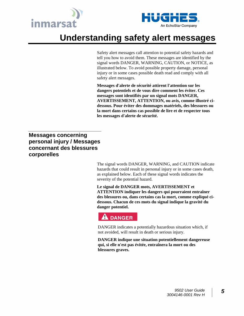
DANGER indicates a potentially hazardous situation which, if
not avoided, will result in death or serious injury.
DANGER indique une situation potentiellement dangereuse
qui, si elle n'est pas évitée, entraînera la mort ou des
blessures graves.
6 9502 User Guide 3004146-0001 Rev H
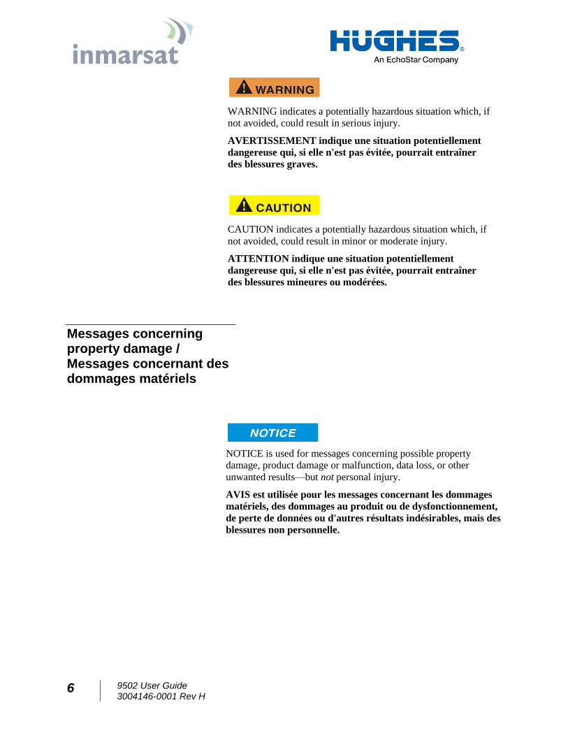
WARNING indicates a potentially hazardous situation which, if
not avoided, could result in serious injury.
AVERTISSEMENT indique une situation potentiellement
dangereuse qui, si elle n'est pas évitée, pourrait entraîner
des blessures graves.
CAUTION indicates a potentially hazardous situation which, if
not avoided, could result in minor or moderate injury.
ATTENTION indique une situation potentiellement
dangereuse qui, si elle n'est pas évitée, pourrait entraîner
des blessures mineures ou modérées.
Messages concerning property damage / Messages concernant des dommages matériels
NOTICE is used for messages concerning possible property
damage, product damage or malfunction, data loss, or other
unwanted results—but not personal injury.
AVIS est utilisée pour les messages concernant les dommages
matériels, des dommages au produit ou de dysfonctionnement,
de perte de données ou d'autres résultats indésirables, mais des
blessures non personnelle.
9502 User Guide 3004146-0001 Rev H
7
Safety symbols
The generic safety alert symbol calls attention to a
potential personal injury hazard. It appears next to the DANGER,
WARNING, and CAUTION signal words as part of the signal
word label. Other symbols may appear next to DANGER,
WARNING, or CAUTION to indicate a specific type of hazard
(for example, fire or electric shock). If other hazard symbols are
used in this document they are identified in this section.
Le symbole générique d'alerte suivant attire
l'attention sur un danger potentiel de risque de blessures. Il
apparaît à côté des mots DANGER, AVERTISSEMENT et
ATTENTION dans le cadre de l'affichage d’alerte . D'autres
symboles peuvent apparaître à côté de DANGER,
AVERTISSEMENT ou ATTENTION pour indiquer un type
spécifique de danger (par exemple, un incendie ou un choc
électrique). Si d’autres symboles de danger sont utilisés dans
ce document, ils sont décrits dans cette section.
Additional symbols / Symboles supplémentaires
Warning Potential Radio Frequency (RF)
hazard. Where you see this alert symbol and
WARNING heading, strictly follow the warning
instructions to avoid injury to eyes or other
personal injury.
Avertissement Danger possible de Fréquence
Radio (RF). A la vue de ce symbole d’alerte
et du terme AVERTISSEMENT, suivez
rigoureusement les instructions
d'avertissement afin d’éviter une blessure
aux yeux ou toute autre blessure .
Warning Where you see this alert symbol and
WARNING heading, strictly follow the warning
instructions to avoid personal injury.
Avertissement A la vue de ce symbole
d’alerte et du terme AVERTISSEMENT,
suivez rigoureusement les instructions
d'avertissement pour éviter toute blessure.
8 9502 User Guide 3004146-0001 Rev H
Danger Electric shock hazard: Where you see
this alert symbol and DANGER heading,
strictly follow the warning instructions to avoid
electric shock injury or death.
Danger Risque de choc électrique: A la vue
de ce symbole d’alerte et du terme DANGER,
suivez rigoureusement les instructions
d'avertissement pour éviter tout choc
électrique ou blessure mortelle.
Warnings for Satellite Terminal / Avertissements pour le Terminal Satellite
Do not stand in front of the ODU (Antenna)
This device emits radio frequency energy. To
avoid injury, do not place head or other body
parts in front of the satellite ODU when system
is operational. Maintain a distance of 1 m or
more from the front of the Satellite Terminal
ODU.
Ne pas se tenir en face de l'ODU (antenne)
Cet appareil émet une énergie de fréquence
radio. Pour éviter toute blessure, ne placez
pas la tête ou toute autre partie du corps en
face de l'ODU satellite lorsque le système est
opérationnel. Maintenez une distance de 1 m
ou plus par rapport à l’ODU du terminal
satellite.
General Handle your Satellite Terminal with
care. Avoid exposing your Satellite Terminal to
extreme hot or cold temperatures outside the
range -40ºC to +75ºC.
Avoid placing the Terminal close to cigarettes,
open flames or any source of heat.
Changes or modifications to the Terminal not
expressly approved by Hughes Network
Systems will void the Warranty and could void
your authority to operate this equipment.
Only use a soft damp cloth to clean the
Terminal.
9502 User Guide 3004146-0001 Rev H
9
To avoid impaired Terminal performance, please
ensure the unit’s ODU is not damaged or
covered with foreign material like paint or
labeling.
When inserting the SIM, do not bend it or
damage the contacts in any way. When
connecting the interface cables, do not use
excessive force.
Général Manipulez votre terminal satellite
avec soin. Évitez d'exposer votre terminal
satellite à des températures extrêmement
chaudes ou froides en dehors de la plage -40 º
C à 75 º C.
Évitez de placer le terminal à proximité de la
cigarette, de flammes nues ou de toute source
de chaleur.
Les changements ou modifications apportées
au Terminal et non expressément approuvées
par Hughes Network Systems annulent la
garantie et peuvent annuler votre droit à
utiliser cet équipement.
Utilisez uniquement un chiffon doux humide
pour nettoyer le terminal.
Pour éviter toute dégradation des
performances du terminal , veuillez vous
assurer que l’ODU de l'unité n'est pas
endommagée ou recouverte d’un corps
étranger, comme de la peinture ou de
l'étiquetage.
Lorsque vous insérez la carte SIM, ne pas la
plier ni endommager les contacts en aucune
manière. Ne pas forcer lors de la connexion
des câbles d’interface.
In the vicinity of blasting work and in
explosive environments Never use the Satellite
Terminal where blasting work is in progress.
Observe all restrictions and follow any
regulations or rules. Areas with a potentially
explosive environment are often, but not always,
clearly marked.
A proximité de travaux de dynamitage et
d’environnements explosifs N'utilisez jamais
le terminal satellite près de travaux de
dynamitage en cours. Respectez toutes les
10 9502 User Guide 3004146-0001 Rev H
restrictions et suivez toutes les instructions
ou la règlementation. Les zones présentant
une atmosphère potentiellement explosive
sont généralement, mais pas toujours,
clairement signalées.
Qualified Service Do not attempt to
disassemble your Satellite Terminal. The unit
does not contain consumer-serviceable
components. Only qualified service personnel
may install or repair equipment.
Service Qualifié N'essayez pas de démonter
votre terminal satellite. L'unité ne contient
pas de composants réparables par le
consommateur. Seul le personnel qualifié
peut installer ou réparer le matériel.
Accessories Use Hughes approved accessories
only. Use of non-approved accessories may
result in loss of performance, damage to the
Satellite Terminal, fire, electric shock or injury.
Accessoires Utilisez uniquement des
accessoires approuvés par Hughes.
L’utilisation d’accessoires non approuvés
peut entraîner une dégradation de
performance, un endommagement du
terminal satellite, un incendie, une
électrocution ou des blessures.
Connecting Devices Never connect
incompatible devices to the Satellite Terminal.
When connecting the Satellite Terminal to any
other device, read the device’s User Manual for
detailed safety instructions.
Connexion de périphériques Ne jamais
connecter des périphériques incompatibles
au terminal satellite. Lors du raccordement
du terminal satellite à un autre appareil, lire
le manuel utilisateur du périphérique pour
les instructions détaillées de sécurité.
Pacemakers The various brands and models of
cardiac pacemakers available exhibit a wide range
of immunity levels to radio signals. Therefore,
people who wear a cardiac pacemaker and who
want to use a Satellite Terminal should seek the
9502 User Guide 3004146-0001 Rev H
11
advice of their cardiologist. If, as a pacemaker
user, you are still concerned about interaction with
the Satellite Terminal, we suggest you follow these
guidelines:
Maintain a distance of one meter from the
front and sides of the ODU and your
pacemaker;
Refer to your pacemaker product literature
for information on your particular device.
If you have any reason to suspect that interference
is taking place, turn off your Satellite Terminal
immediately.
Stimulateurs Cardiaques Les différentes
marques et modèles de stimulateurs cardiaques
disponibles présentent un large éventail de
niveaux d'immunité aux signaux radio. Par
conséquent, les personnes qui portent un
stimulateur cardiaque et qui veulent utiliser un
terminal satellite doivent demander l'avis de
leur cardiologue. Si, en tant qu'utilisateur de
stimulateur cardiaque, vous êtes toujours
soucieux d’une éventuelle interaction avec le
terminal satellite, nous vous suggérons de suivre
ces directives:
Maintenez un mètre de distance entre
votre stimulateur cardiaque et l'avant ou
les côtés de l'ODU;
Reportez-vous à la documentation de
votre stimulateur cardiaque pour toute
information spécifique à celui-ci.
Si vous avez un doute que des interférences se
produisent, éteignez votre terminal satellite
immédiatement.
Hearing Aids Most new models of hearing aids
are immune to radio frequency interference from
Satellite Terminals that are more than 2 meters
away. Many types of older hearing aids may be
susceptible to interference, making it very difficult
12 9502 User Guide 3004146-0001 Rev H
to use them near a Terminal. Should interference
be experienced, maintain additional separation
between you and the Satellite Terminal.
Appareils Auditifs La plupart des nouveaux
appareils auditifs sont insensibles aux
interférences dues aux fréquences radio des
terminaux satellites situés à plus de 2 m . De
nombreux modèles plus anciens peuvent être
sensibles aux interférences, ce qui les rend très
difficiles à utiliser à proximité d’un terminal.
En cas d’interférences détectées, veuillez
maintenir une distance supplémentaire entre
vous et le terminal.
Electrical Storms installation of the Satellite
Terminal during electrical storms may result in
severe personal injury or death.
Orages Electriques L’installation d’un terminal
satellite pendant un orage électrique peut
entrainer des blessures graves ou mortelles.
Protective Earth Grounding is recommended by
Hughes for both the IDU and the ODU equipment.
Please consult professional local advice for these
requirements.
Une mise à la terre de protection est
recommandée par Hughes à la fois pour l'IDU
et le matériel ODU. Veuillez consulter un
conseil professionnel local pour ces
spécifications.
9502 User Guide 3004146-0001 Rev H
13
Chapter 1 Product Description
Contents of the Hughes 9502 Kit
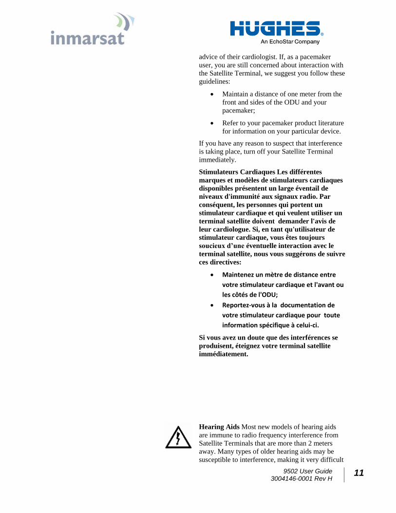
The Hughes 9502 Kit (P/N 3500509-0001) is a two piece design
that comes with an Indoor Unit (IDU), an Outdoor Unit (ODU) and
a 10 meter RF cable that has an N type connection at both ends and
an N to TNC adapter inside the cable bag for connection to the
IDU.
Figure 1-1 – IDU P/N 3500563-0001
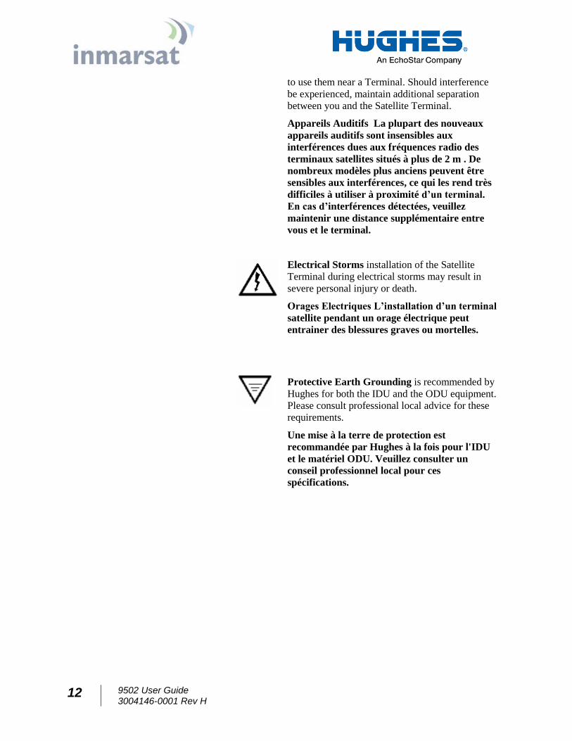
Figure 1-2 – RF Cable with N to TNC adapter P/N 3500634-0001
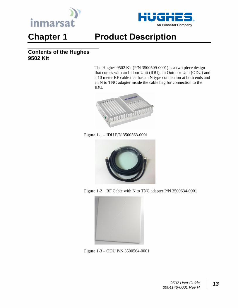
Figure 1-3 – ODU P/N 3500564-0001
14 9502 User Guide 3004146-0001 Rev H
Optional Mounting Accessories
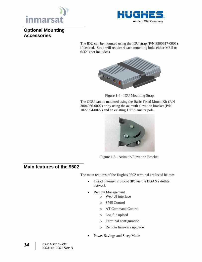
The IDU can be mounted using the IDU strap (P/N 3500617-0001)
if desired. Strap will require 4 each mounting bolts either M3.5 or
6/32” (not included).
Figure 1-4 - IDU Mounting Strap
The ODU can be mounted using the Basic Fixed Mount Kit (P/N
3004066-0002) or by using the azimuth elevation bracket (P/N
1022994-0022) and an existing 1.5” diameter pole.
Figure 1-5 - Azimuth/Elevation Bracket
Main features of the 9502
The main features of the Hughes 9502 terminal are listed below:
Use of Internet Protocol (IP) via the BGAN satellite
network
Remote Management
o Web UI interface
o SMS Control
o AT Command Control
o Log file upload
o Terminal configuration
o Remote firmware upgrade
Power Savings and Sleep Mode
9502 User Guide 3004146-0001 Rev H
15
IP Watchdog
Install Mode
XL-band ready
NAT, NAPT and Relay Modes
Auto Power ON when power is applied
Automatic PDP Context Activation (Static or DHCP)
Dedicated M2M webUI
Security
o Ethernet MAC Filtering
o Administration Password
o SMS Control password
o White List for SMS control
o AT Command password lock
o SIM Personalization
Phone-to-SIM
DP SIM Lock
SP SIM Lock
Interfaces
The Hughes 9502 has the following interfaces:
Ethernet connection (RJ45)
USB 1.1 connection (USB Type-B) for PC to configure
terminal (requires installation of Hughes USB driver. See www.bgan.hughes.com )
TNC type RF connector on IDU and N-type RF connector
on the ODU
Integrated GPS receiver and L-band ODU
RS232 serial interface (DB9 male, DTE) to external
NMEA 0183 based GNSS device (e.g., GLONASS
receiver). This port cannot be used for serial data.
16 9502 User Guide 3004146-0001 Rev H
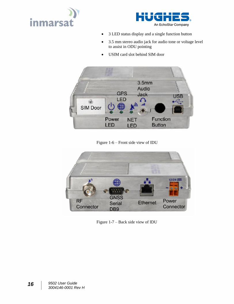
3 LED status display and a single function button
3.5 mm stereo audio jack for audio tone or voltage level
to assist in ODU pointing
USIM card slot behind SIM door
Figure 1-6 – Front side view of IDU
Figure 1-7 – Back side view of IDU
9502 User Guide 3004146-0001 Rev H
17
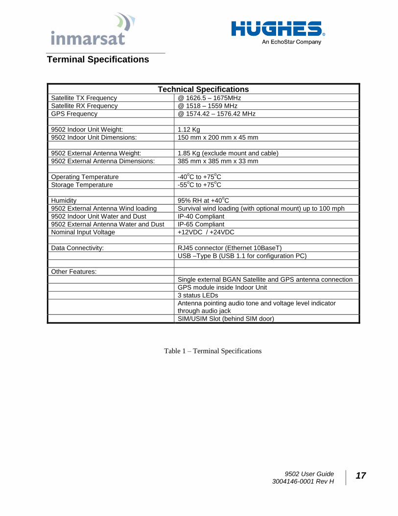
Terminal Specifications
Technical Specifications Satellite TX Frequency @ 1626.5 – 1675MHz
Satellite RX Frequency @ 1518 – 1559 MHz
GPS Frequency @ 1574.42 – 1576.42 MHz
9502 Indoor Unit Weight: 1.12 Kg
9502 Indoor Unit Dimensions: 150 mm x 200 mm x 45 mm
9502 External Antenna Weight: 1.85 Kg (exclude mount and cable)
9502 External Antenna Dimensions: 385 mm x 385 mm x 33 mm
Operating Temperature -40oC to +75
oC
Storage Temperature -55oC to +75
oC
Humidity 95% RH at +40oC
9502 External Antenna Wind loading Survival wind loading (with optional mount) up to 100 mph
9502 Indoor Unit Water and Dust IP-40 Compliant
9502 External Antenna Water and Dust IP-65 Compliant
Nominal Input Voltage +12VDC / +24VDC
Data Connectivity: RJ45 connector (Ethernet 10BaseT)
USB –Type B (USB 1.1 for configuration PC)
Other Features:
Single external BGAN Satellite and GPS antenna connection
GPS module inside Indoor Unit
3 status LEDs
Antenna pointing audio tone and voltage level indicator through audio jack
SIM/USIM Slot (behind SIM door)
Table 1 – Terminal Specifications
18 9502 User Guide 3004146-0001 Rev H
Chapter 2 Configuration via Web UI
The UT is typically configured via the Web User Interface (UI).
Browsers that are currently supported are IE7 and newer, Mozilla,
and Safari only.
Web UI Layout
The Web User Interface (UI) can be accessed from a MAC or PC
browser by entering 192.168.128.100 as the URL (unless you
change the IP address of the UT.)
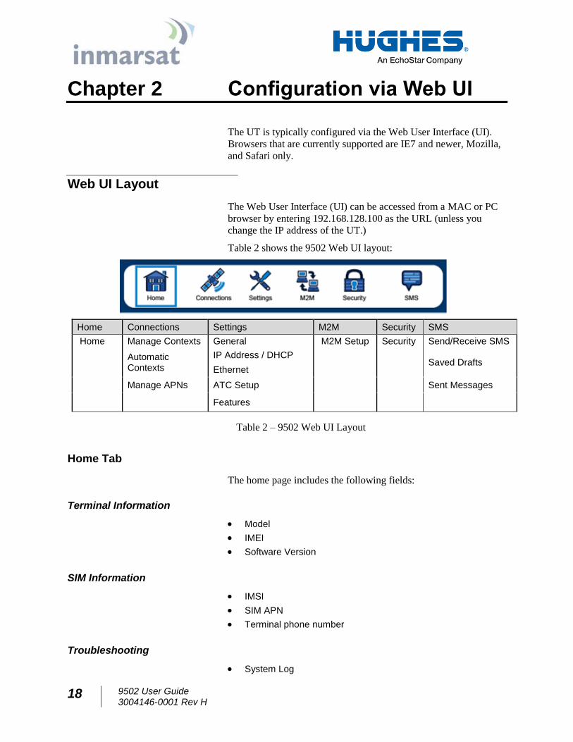
Table 2 shows the 9502 Web UI layout:
Home Connections Settings M2M Security SMS
Home Manage Contexts General M2M Setup Security Send/Receive SMS
Automatic Contexts
IP Address / DHCP Saved Drafts
Ethernet
Manage APNs ATC Setup Sent Messages
Features
Table 2 – 9502 Web UI Layout
Home Tab
The home page includes the following fields:
Terminal Information
Model
IMEI
Software Version
SIM Information
IMSI
SIM APN
Terminal phone number
Troubleshooting
System Log
9502 User Guide 3004146-0001 Rev H
19
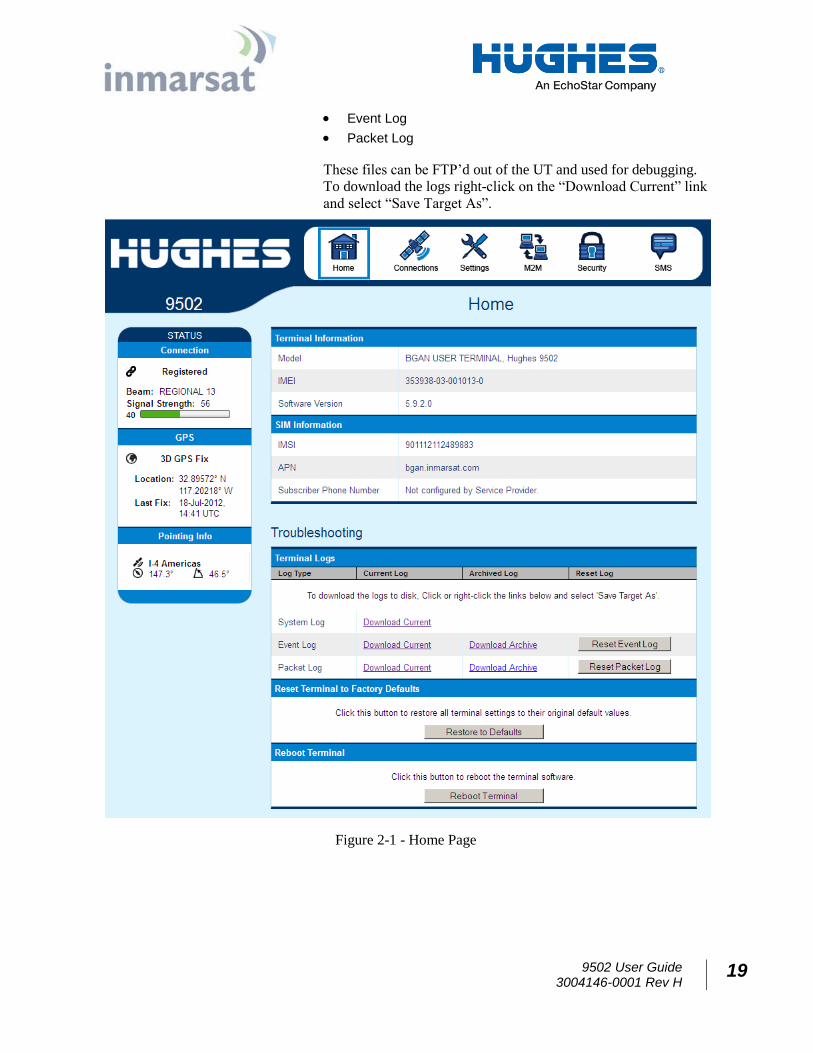
Event Log
Packet Log
These files can be FTP’d out of the UT and used for debugging.
To download the logs right-click on the “Download Current” link
and select “Save Target As”.
Figure 2-1 - Home Page
20 9502 User Guide 3004146-0001 Rev H
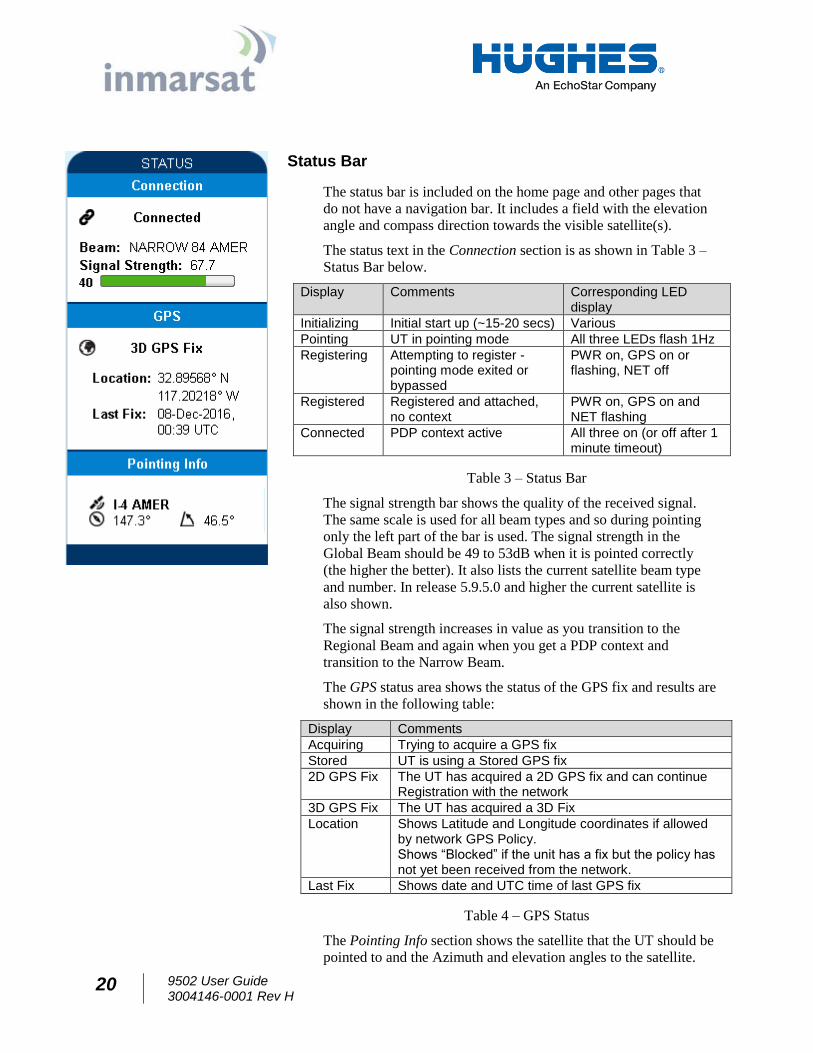
Status Bar
The status bar is included on the home page and other pages that
do not have a navigation bar. It includes a field with the elevation
angle and compass direction towards the visible satellite(s).
The status text in the Connection section is as shown in Table 3 –
Status Bar below.
Display Comments Corresponding LED display
Initializing Initial start up (~15-20 secs) Various
Pointing UT in pointing mode All three LEDs flash 1Hz
Registering Attempting to register - pointing mode exited or bypassed
PWR on, GPS on or flashing, NET off
Registered Registered and attached, no context
PWR on, GPS on and NET flashing
Connected PDP context active All three on (or off after 1 minute timeout)
Table 3 – Status Bar
The signal strength bar shows the quality of the received signal.
The same scale is used for all beam types and so during pointing
only the left part of the bar is used. The signal strength in the
Global Beam should be 49 to 53dB when it is pointed correctly
(the higher the better). It also lists the current satellite beam type
and number. In release 5.9.5.0 and higher the current satellite is
also shown.
The signal strength increases in value as you transition to the
Regional Beam and again when you get a PDP context and
transition to the Narrow Beam.
The GPS status area shows the status of the GPS fix and results are
shown in the following table:
Display Comments
Acquiring Trying to acquire a GPS fix
Stored UT is using a Stored GPS fix
2D GPS Fix The UT has acquired a 2D GPS fix and can continue Registration with the network
3D GPS Fix The UT has acquired a 3D Fix
Location Shows Latitude and Longitude coordinates if allowed by network GPS Policy. Shows “Blocked” if the unit has a fix but the policy has not yet been received from the network.
Last Fix Shows date and UTC time of last GPS fix
Table 4 – GPS Status
The Pointing Info section shows the satellite that the UT should be
pointed to and the Azimuth and elevation angles to the satellite.
9502 User Guide 3004146-0001 Rev H
21
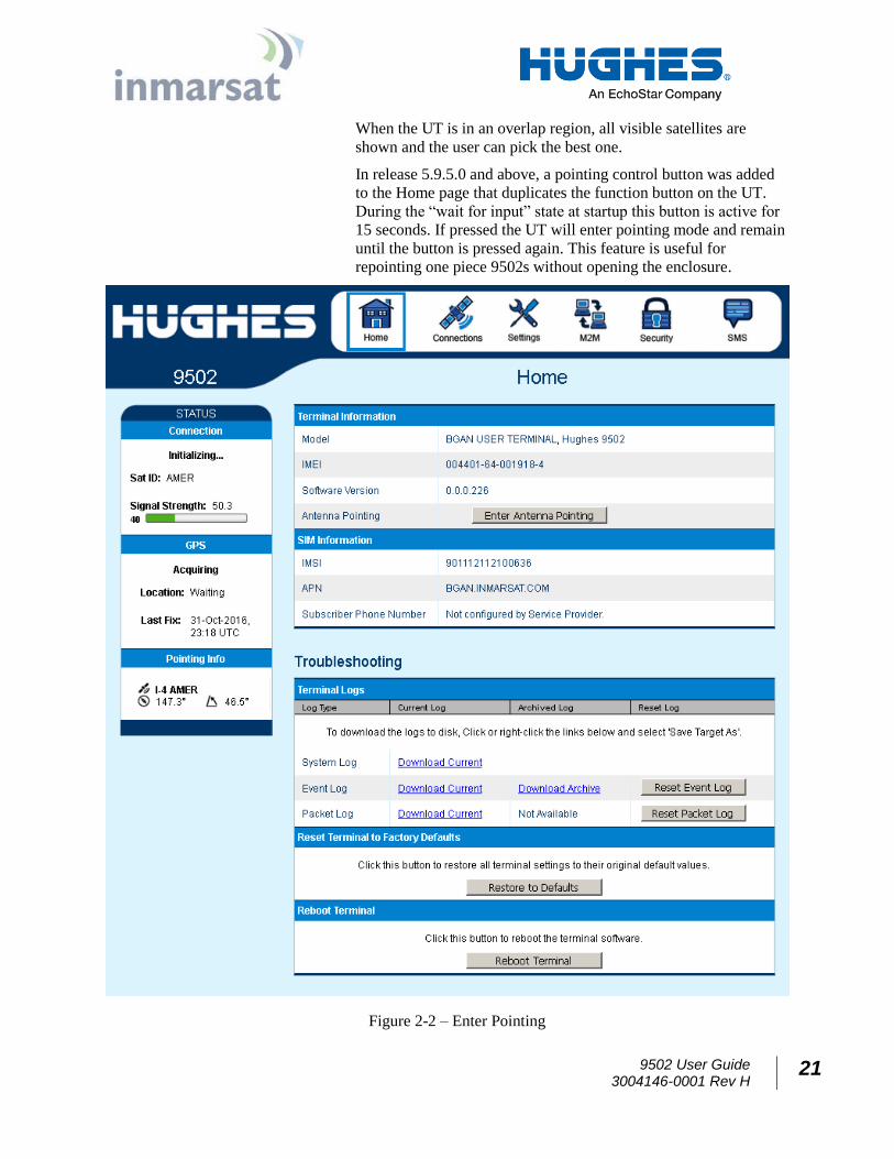
When the UT is in an overlap region, all visible satellites are
shown and the user can pick the best one.
In release 5.9.5.0 and above, a pointing control button was added
to the Home page that duplicates the function button on the UT.
During the “wait for input” state at startup this button is active for
15 seconds. If pressed the UT will enter pointing mode and remain
until the button is pressed again. This feature is useful for
repointing one piece 9502s without opening the enclosure.
Figure 2-2 – Enter Pointing
22 9502 User Guide 3004146-0001 Rev H
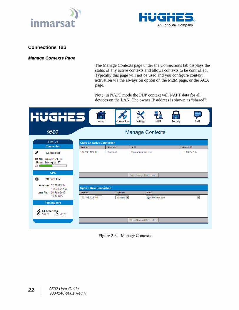
Connections Tab
Manage Contexts Page
The Manage Contexts page under the Connections tab displays the
status of any active contexts and allows contexts to be controlled.
Typically this page will not be used and you configure context
activation via the always on option on the M2M page, or the ACA
page.
Note, in NAPT mode the PDP context will NAPT data for all
devices on the LAN. The owner IP address is shown as “shared”.
Figure 2-3 – Manage Contexts
9502 User Guide 3004146-0001 Rev H
23
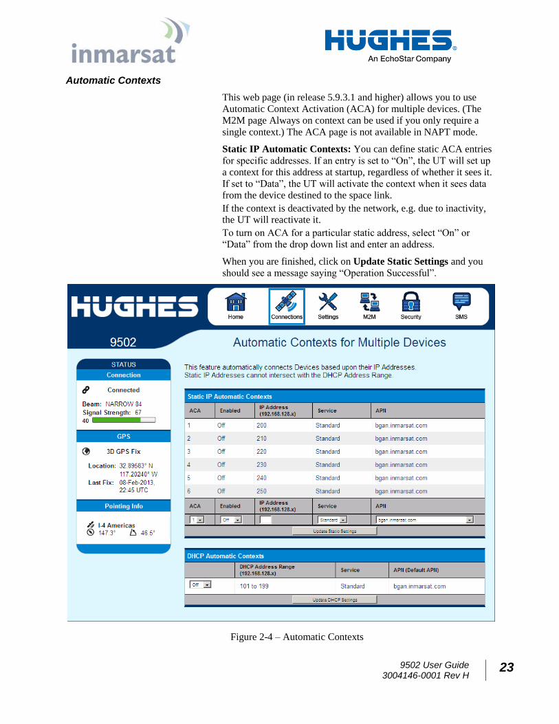
Automatic Contexts
This web page (in release 5.9.3.1 and higher) allows you to use
Automatic Context Activation (ACA) for multiple devices. (The
M2M page Always on context can be used if you only require a
single context.) The ACA page is not available in NAPT mode.
Static IP Automatic Contexts: You can define static ACA entries
for specific addresses. If an entry is set to “On”, the UT will set up
a context for this address at startup, regardless of whether it sees it.
If set to “Data”, the UT will activate the context when it sees data
from the device destined to the space link.
If the context is deactivated by the network, e.g. due to inactivity, the UT will reactivate it.
To turn on ACA for a particular static address, select “On” or
“Data” from the drop down list and enter an address.
When you are finished, click on Update Static Settings and you
should see a message saying “Operation Successful”.
Figure 2-4 – Automatic Contexts
24 9502 User Guide 3004146-0001 Rev H
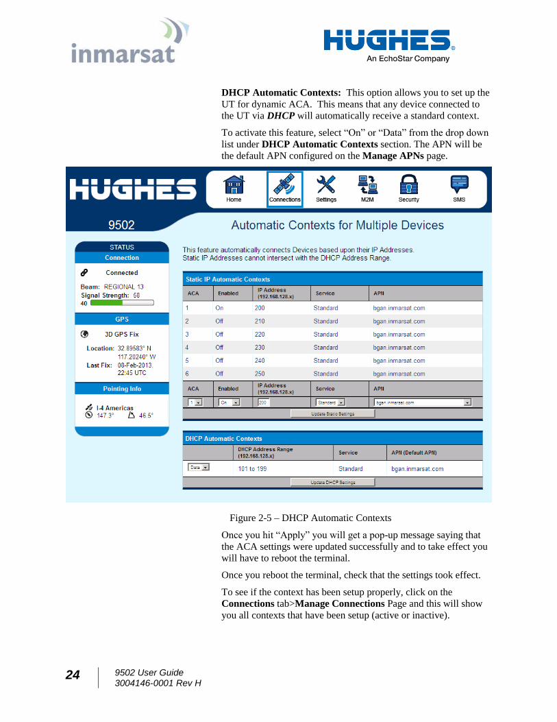
DHCP Automatic Contexts: This option allows you to set up the
UT for dynamic ACA. This means that any device connected to
the UT via DHCP will automatically receive a standard context.
To activate this feature, select “On” or “Data” from the drop down
list under DHCP Automatic Contexts section. The APN will be
the default APN configured on the Manage APNs page.
Figure 2-5 – DHCP Automatic Contexts
Once you hit “Apply” you will get a pop-up message saying that
the ACA settings were updated successfully and to take effect you
will have to reboot the terminal.
Once you reboot the terminal, check that the settings took effect.
To see if the context has been setup properly, click on the
Connections tab>Manage Connections Page and this will show
you all contexts that have been setup (active or inactive).
9502 User Guide 3004146-0001 Rev H
25
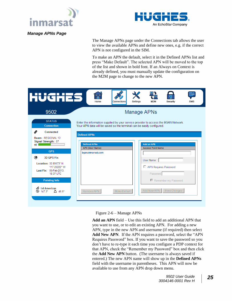
Manage APNs Page
The Manage APNs page under the Connections tab allows the user
to view the available APNs and define new ones, e.g. if the correct
APN is not configured in the SIM.
To make an APN the default, select it in the Defined APNs list and
press “Make Default”. The selected APN will be moved to the top
of the list and shown in bold font. If an Always on Context is
already defined, you must manually update the configuration on
the M2M page to change to the new APN.
Figure 2-6 – Manage APNs
Add an APN field – Use this field to add an additional APN that
you want to use, or to edit an existing APN. For adding a new
APN, type in the new APN and username (if required) then select
Add New APN. If the APN requires a password, select the “APN
Requires Password” box. If you want to save the password so you
don’t have to re-type it each time you configure a PDP context for
that APN, check the “Remember my Password” box and then click
the Add New APN button. (The username is always saved if
entered.) The new APN name will show up in the Defined APNs
field with the username in parentheses. This APN will now be
available to use from any APN drop down menu.
26 9502 User Guide 3004146-0001 Rev H
Settings Tab
The settings tab has the following configuration pages:
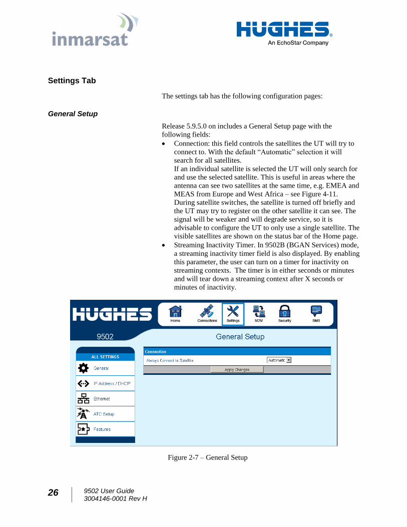
General Setup
Release 5.9.5.0 on includes a General Setup page with the
following fields:
Connection: this field controls the satellites the UT will try to
connect to. With the default “Automatic” selection it will
search for all satellites.
If an individual satellite is selected the UT will only search for
and use the selected satellite. This is useful in areas where the
antenna can see two satellites at the same time, e.g. EMEA and
MEAS from Europe and West Africa – see Figure 4-11.
During satellite switches, the satellite is turned off briefly and
the UT may try to register on the other satellite it can see. The
signal will be weaker and will degrade service, so it is
advisable to configure the UT to only use a single satellite. The
visible satellites are shown on the status bar of the Home page.
Streaming Inactivity Timer. In 9502B (BGAN Services) mode,
a streaming inactivity timer field is also displayed. By enabling
this parameter, the user can turn on a timer for inactivity on
streaming contexts. The timer is in either seconds or minutes
and will tear down a streaming context after X seconds or
minutes of inactivity.
Figure 2-7 – General Setup
9502 User Guide 3004146-0001 Rev H
27
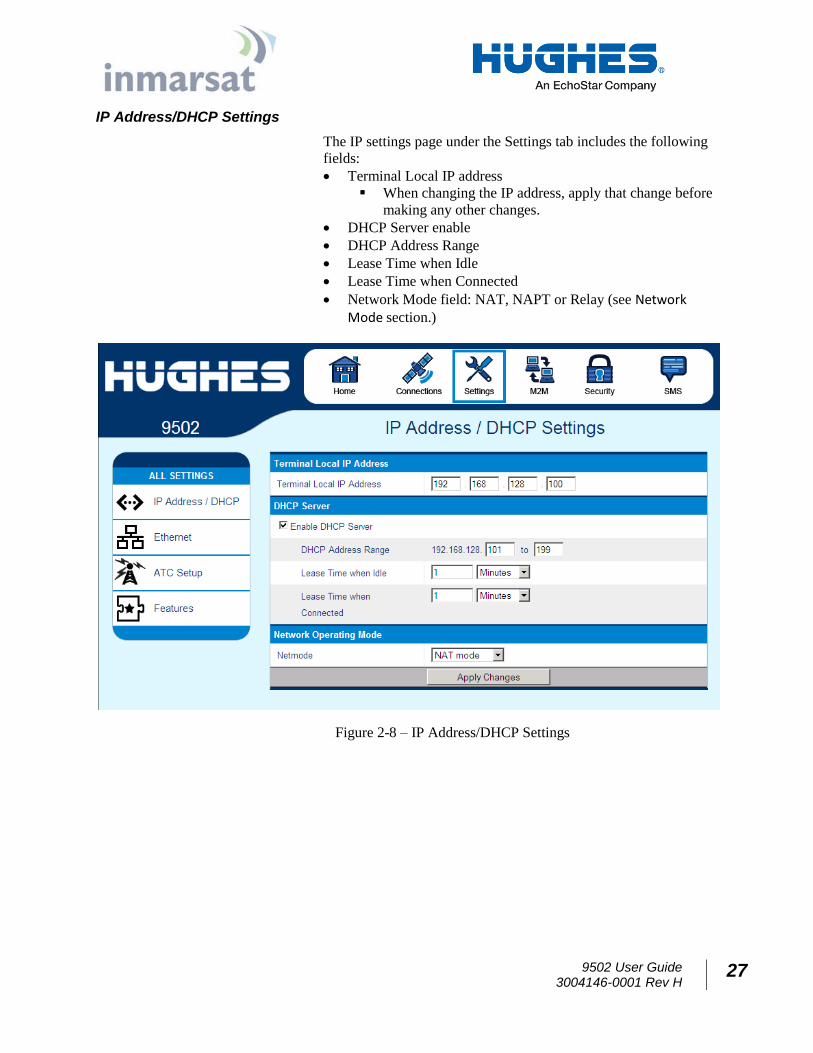
IP Address/DHCP Settings
The IP settings page under the Settings tab includes the following
fields:
Terminal Local IP address
When changing the IP address, apply that change before
making any other changes.
DHCP Server enable
DHCP Address Range
Lease Time when Idle
Lease Time when Connected
Network Mode field: NAT, NAPT or Relay (see Network Mode section.)
Figure 2-8 – IP Address/DHCP Settings
28 9502 User Guide 3004146-0001 Rev H
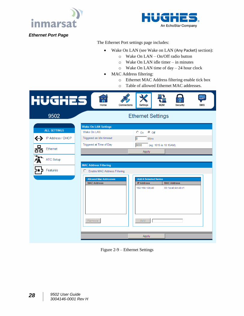
Ethernet Port Page
The Ethernet Port settings page includes:
Wake On LAN (see Wake on LAN (Any Packet) section):
o Wake On LAN – On/Off radio button
o Wake On LAN idle timer – in minutes
o Wake On LAN time of day – 24 hour clock
MAC Address filtering:
o Ethernet MAC Address filtering enable tick box
o Table of allowed Ethernet MAC addresses.
Figure 2-9 – Ethernet Settings
9502 User Guide 3004146-0001 Rev H
29
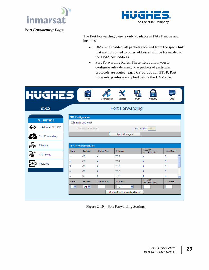
Port Forwarding Page
The Port Forwarding page is only available in NAPT mode and
includes:
DMZ – if enabled, all packets received from the space link
that are not routed to other addresses will be forwarded to
the DMZ host address.
Port Forwarding Rules. These fields allow you to
configure rules defining how packets of particular
protocols are routed, e.g. TCP port 80 for HTTP. Port
Forwarding rules are applied before the DMZ rule.
Figure 2-10 – Port Forwarding Settings
30 9502 User Guide 3004146-0001 Rev H
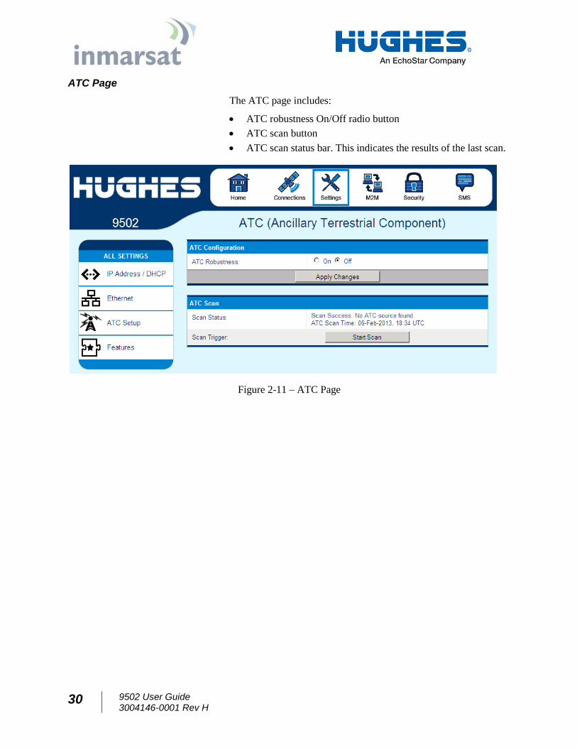
ATC Page
The ATC page includes:
ATC robustness On/Off radio button
ATC scan button
ATC scan status bar. This indicates the results of the last scan.
Figure 2-11 – ATC Page
9502 User Guide 3004146-0001 Rev H
31
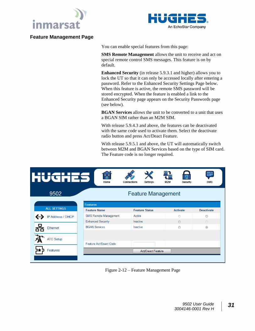
Feature Management Page
You can enable special features from this page:
SMS Remote Management allows the unit to receive and act on
special remote control SMS messages. This feature is on by
default.
Enhanced Security (in release 5.9.3.1 and higher) allows you to
lock the UT so that it can only be accessed locally after entering a
password. Refer to the Enhanced Security Settings Page below.
When this feature is active, the remote SMS password will be
stored encrypted. When the feature is enabled a link to the
Enhanced Security page appears on the Security Passwords page
(see below).
BGAN Services allows the unit to be converted to a unit that uses
a BGAN SIM rather than an M2M SIM.
With release 5.9.4.3 and above, the features can be deactivated
with the same code used to activate them. Select the deactivate
radio button and press Act/Deact Feature.
With release 5.9.5.1 and above, the UT will automatically switch
between M2M and BGAN Services based on the type of SIM card.
The Feature code is no longer required.
Figure 2-12 – Feature Management Page
32 9502 User Guide 3004146-0001 Rev H
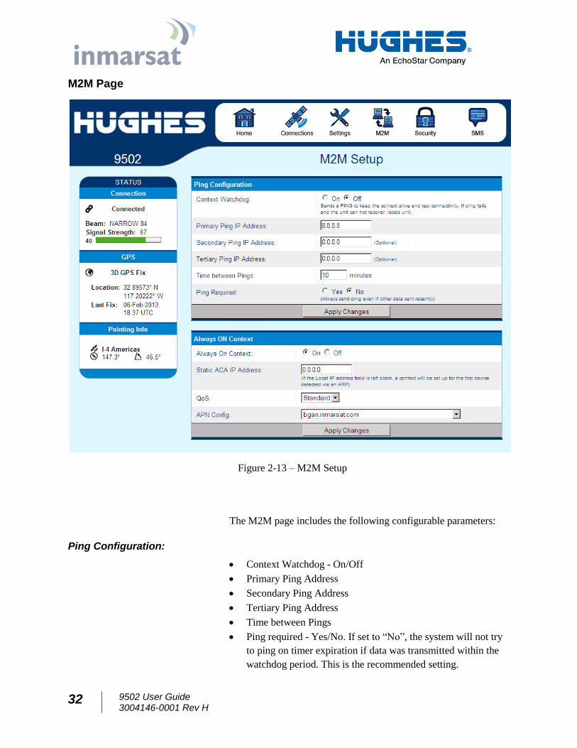
M2M Page
Figure 2-13 – M2M Setup
The M2M page includes the following configurable parameters:
Ping Configuration:
Context Watchdog - On/Off
Primary Ping Address
Secondary Ping Address
Tertiary Ping Address
Time between Pings
Ping required - Yes/No. If set to “No”, the system will not try
to ping on timer expiration if data was transmitted within the
watchdog period. This is the recommended setting.
9502 User Guide 3004146-0001 Rev H
33
Always On Context:
Always on context - On/Off (default is On)
Always on static IP address. If the TE has a known static IP
address or never ARPs, enter this address. Alternatively, leave
the IP address blank (0.0.0.0) and the UT will set up a context
for the first device it detects through ARP during startup.
APN drop down box
34 9502 User Guide 3004146-0001 Rev H
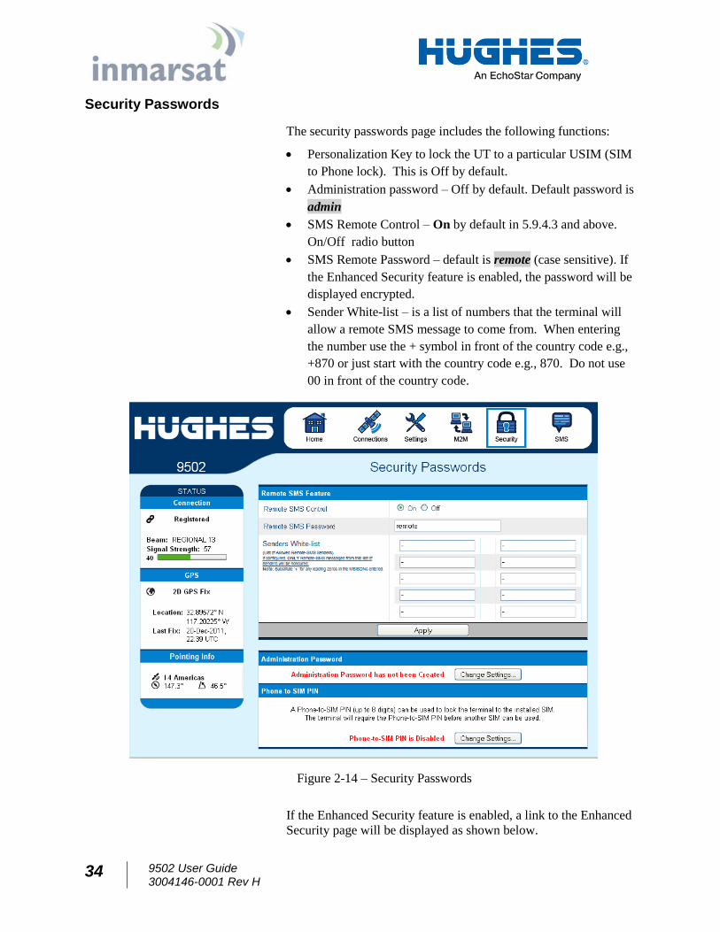
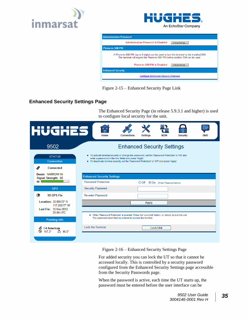
Security Passwords
The security passwords page includes the following functions:
Personalization Key to lock the UT to a particular USIM (SIM
to Phone lock). This is Off by default.
Administration password – Off by default. Default password is
admin
SMS Remote Control – On by default in 5.9.4.3 and above.
On/Off radio button
SMS Remote Password – default is remote (case sensitive). If
the Enhanced Security feature is enabled, the password will be
displayed encrypted.
Sender White-list – is a list of numbers that the terminal will
allow a remote SMS message to come from. When entering
the number use the + symbol in front of the country code e.g.,
+870 or just start with the country code e.g., 870. Do not use
00 in front of the country code.
Figure 2-14 – Security Passwords
If the Enhanced Security feature is enabled, a link to the Enhanced
Security page will be displayed as shown below.
9502 User Guide 3004146-0001 Rev H
35
Figure 2-15 – Enhanced Security Page Link
Enhanced Security Settings Page
The Enhanced Security Page (in release 5.9.3.1 and higher) is used
to configure local security for the unit.
Figure 2-16 – Enhanced Security Settings Page
For added security you can lock the UT so that it cannot be
accessed locally. This is controlled by a security password
configured from the Enhanced Security Settings page accessible
from the Security Passwords page.
When the password is active, each time the UT starts up, the
password must be entered before the user interface can be
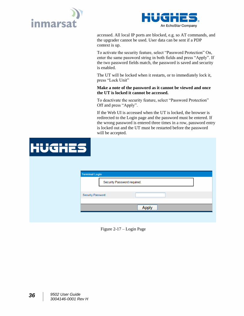
36 9502 User Guide 3004146-0001 Rev H
accessed. All local IP ports are blocked, e.g. so AT commands, and
the upgrader cannot be used. User data can be sent if a PDP
context is up.
To activate the security feature, select “Password Protection” On,
enter the same password string in both fields and press “Apply”. If
the two password fields match, the password is saved and security
is enabled.
The UT will be locked when it restarts, or to immediately lock it,
press “Lock Unit”
Make a note of the password as it cannot be viewed and once
the UT is locked it cannot be accessed.
To deactivate the security feature, select “Password Protection”
Off and press “Apply”.
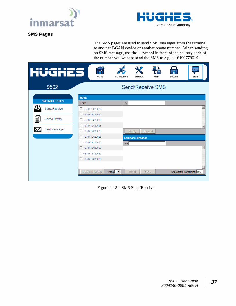
If the Web UI is accessed when the UT is locked, the browser is
redirected to the Login page and the password must be entered. If
the wrong password is entered three times in a row, password entry
is locked out and the UT must be restarted before the password
will be accepted.
Figure 2-17 – Login Page
9502 User Guide 3004146-0001 Rev H
37
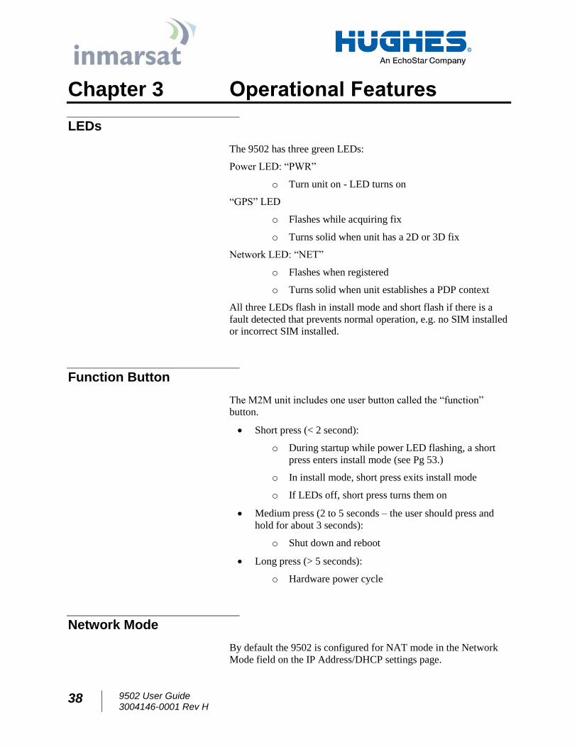
SMS Pages
The SMS pages are used to send SMS messages from the terminal
to another BGAN device or another phone number. When sending
an SMS message, use the + symbol in front of the country code of
the number you want to send the SMS to e.g., +16199778619.
Figure 2-18 – SMS Send/Receive
38 9502 User Guide 3004146-0001 Rev H
Chapter 3 Operational Features
LEDs
The 9502 has three green LEDs:
Power LED: “PWR”
o Turn unit on - LED turns on
“GPS” LED
o Flashes while acquiring fix
o Turns solid when unit has a 2D or 3D fix
Network LED: “NET”
o Flashes when registered
o Turns solid when unit establishes a PDP context
All three LEDs flash in install mode and short flash if there is a
fault detected that prevents normal operation, e.g. no SIM installed
or incorrect SIM installed.
Function Button
The M2M unit includes one user button called the “function”
button.
Short press (< 2 second):
o During startup while power LED flashing, a short
press enters install mode (see Pg 53.)
o In install mode, short press exits install mode
o If LEDs off, short press turns them on
Medium press (2 to 5 seconds – the user should press and
hold for about 3 seconds):
o Shut down and reboot
Long press (> 5 seconds):
o Hardware power cycle
Network Mode
By default the 9502 is configured for NAT mode in the Network
Mode field on the IP Address/DHCP settings page.
9502 User Guide 3004146-0001 Rev H
39
NAT Mode
In NAT mode once a PDP context is active, the UT will translate
between the local and global IP addresses. This is a basic NAT that
only performs IP address translation. It does not use port
translation.
NAPT Mode
In NAPT mode (5.9.4.4 and above) multiple devices connected via
a hub or switch share a single PDP context. The port translating
NAT modifies both IP addresses and port numbers so multiple
devices can share the single global IP address assigned to the PDP
context.
In NAPT mode, only a single context is supported. By default the
Always On Context is activated on the M2M page. The ACA page
is removed. A Port Forwarding page is added under Settings and
can be used to configure the DMZ and Port Forwarding.
Relay Mode
In Relay mode the UT will supply the global IP address to the TE
when the context is established. Relay mode is single user and only
supports a single connected TE.
In Relay mode DHCP is required to provide the global IP address
to the TE. When the context is activated, the DHCP server in the
UT will NACK the next DHCP lease renewal from the TE and
assign the global IP address assigned by the network. The local IP
connection will be torn down and reestablished as the IP address
changes. Similarly, when the context is deactivated the DHCP
server will NACK the lease renewal and then reassign the original
private IP address.
The Web UI will lose and reestablish its connection to the terminal
as the IP address is changed.
To make the IP address change happen quickly a short DHCP lease
should be used. The terminal defaults the lease time to 60 seconds
in idle and connected mode.
Relay mode only supports a single user TE. If you need to connect
a laptop via the USB port for configuration and monitoring
purposes, you must set the laptop up with a local static IP address
within the same subnet as the terminal e.g., 192.168.128.200. This
prevents the USB port from getting the single DHCP address when
in Relay mode once you reboot the terminal.
40 9502 User Guide 3004146-0001 Rev H
Remote Control
The 9502 can be controlled remotely via SMS and locally via AT
commands. The AT interface can be used for local control of the
terminal as long as AT commands can be sent by the terminal
equipment (TE) connected. The syntax of all AT commands is
covered in the “Inmarsat BGAN UT-TE Interface Specification”
and the AT command listing supported by the 9502 can be
downloaded from the Hughes website at www.bgan.hughes.com .
The 9502 includes a remote control by SMS feature that supports
the special SMS messages listed in Table 5 – Remote Control SMS
Message Commands. Remote control SMS is supported by default
in the 9502 and does not have to be activated by a feature code.
The syntax of the messages is covered in the “Hughes 9502 SMS
Remote Control Feature User Guide.”
All remote control messages and responses must fit into a single
160 character SMS.
The SMS handler automatically deletes any message that fills the
last SMS slot in the USIM to ensure there is always room to
receive control SMS messages. Control messages are received into
the SIM then read out and deleted so as not to fill up the SIM card.
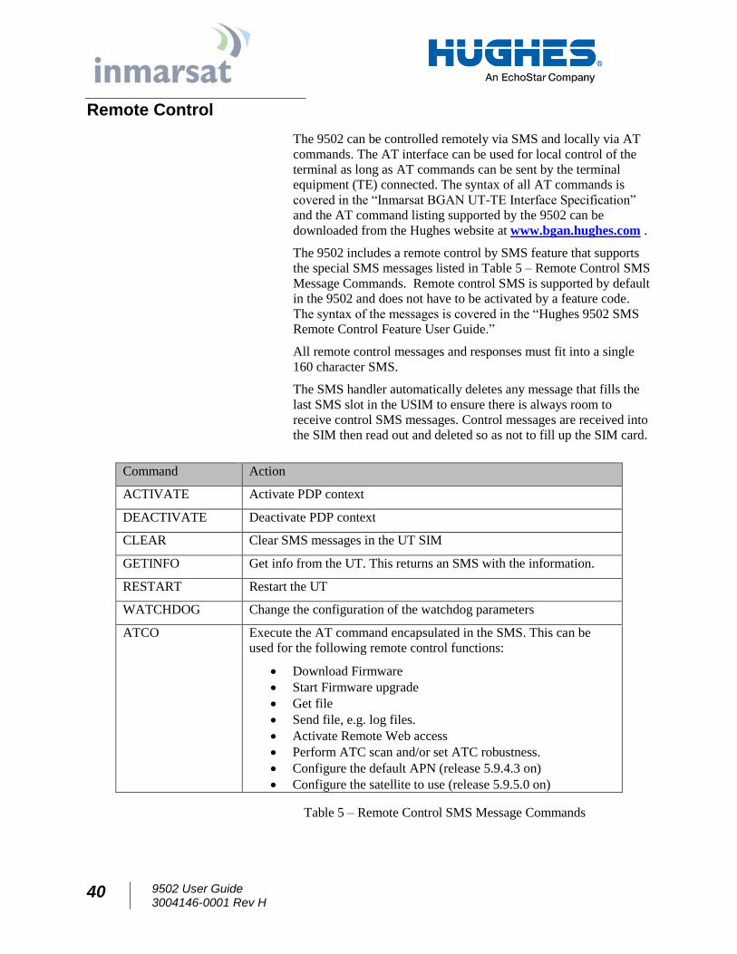
Table 5 – Remote Control SMS Message Commands
Command Action
ACTIVATE Activate PDP context
DEACTIVATE Deactivate PDP context
CLEAR Clear SMS messages in the UT SIM
GETINFO Get info from the UT. This returns an SMS with the information.
RESTART Restart the UT
WATCHDOG Change the configuration of the watchdog parameters
ATCO Execute the AT command encapsulated in the SMS. This can be
used for the following remote control functions:
Download Firmware
Start Firmware upgrade
Get file
Send file, e.g. log files.
Activate Remote Web access
Perform ATC scan and/or set ATC robustness. Configure the default APN (release 5.9.4.3 on) Configure the satellite to use (release 5.9.5.0 on)
9502 User Guide 3004146-0001 Rev H
41
Remote Upgrade and File Transfer
The 9502 includes an FTP client. The operator can send SMS
messages or AT commands to command the 9502 to send or
retrieve files from an FTP server in the network or Internet. This
allows the 9502 to be upgraded, reconfigured and also allows log
files to be sent back to the server. The FTP server can be in the
Inmarsat network, e.g. accessible via a free APN for upgrades; or
can be outside the Inmarsat network, e.g. accessible via a normal
APN for debugging and configuration changes.
The remote upgrade process uses download firmware and firmware
upgrade commands (see “Hughes 9502 SMS Remote Control
Feature User Guide”).
Security
The Web UI includes an admin feature that can be activated from
the security page to prevent unauthorized access to the Web UI.
Additionally the AT command port is locked by default and the
command: AT_ICLCK=”AD”,0,”<admin password>” must be
used to unlock it before AT commands can be used. Both
mechanisms use the same password but the AT commands port
and each Web UI session use a separate lock and must be
individually unlocked.
Support for SMS Remote control is configured from the SMS
settings page. Each Remote Control SMS must include the correct
password. Remote control SMS containing AT commands will be
processed regardless of the Admin setting (they require the feature
to be active and the correct SMS password.)
USIM personalization (or “Phone to SIM lock”) can be used to
lock the UT to a particular SIM.
MAC address filtering on the Ethernet port page allows the user to
define the MAC address of TEs authorized to communicate via the
Ethernet port. Note: The USB port is not included in the MAC
filtering and can be used if the proper USB driver is installed on
the TE.
Wake on LAN (Any Packet)
The UT includes a special low power mode called Wake on LAN
(any packet). From the Web UI you can configure the UT to power
down into this mode after a configurable idle timer or time of day.
Wake on LAN operation is configured from the Ethernet Settings
page (Figure 2-9 – Ethernet Settings) under the Settings tab. It
42 9502 User Guide 3004146-0001 Rev H
includes a configurable idle timer to control when the UT shuts
down into the Wake on LAN mode. The UT declares the link idle
if no packets are received on the Ethernet port within the idle time.
Additionally, the UT can be configured to power down at a
configurable time of day. Enter UTC time as 0001 to 2400. Set to 0
to deactivate the time of day feature. Note that the UT waits 5
minutes after startup before it checks the time of day to see if it has
to power off.
When the UT powers down into this mode it will disconnect from
the BGAN network and monitor the local Ethernet port and power
up again if it sees any Ethernet packet (ARP, DHCP, data packet,
etc). In this mode the power consumption is less than 10mW when
powered from a 12V source. The UT generates Ethernet sync
pulses so the TE believes the link is still active.
When an Ethernet packet is detected the UT will power up
normally, register and bring up a PDP context (if configured for
ACA.) It takes about 1 minute for the UT to be fully connected to
the Inmarsat network.
For this mode to be useful the TE must only send Ethernet packets
when it has data to send over the air. Thus, for example, the TE
should be configured with a static IP address to avoid periodic
DHCP exchanges waking up the UT.
Serial Pin Power Control
The UT can be switched off by applying a voltage to pin 9 of the
DB9 serial port.
If you apply voltage to Pin 9 of the serial port with pin 5 as
Ground, the UT will power down. It will power up when you
remove the voltage.
The voltage can be 2.5V to 50V. 12V is the recommended level.
ATC
The UT includes an extended L-band scanning mode to detect
Auxiliary Terrestrial Component (ATC) or other sources of
external interference. The terminal can be commanded into
scanning mode by the Web UI, AT command or SMS command.
During the scan the terminal will be offline to the BGAN network
and will automatically reboot to return to normal operation.
In scanning mode the terminal measures the received signal
strength across the 41MHz of L-band spectrum (1518 to
1559MHz). Once the scan is complete the UT restarts and
communicates the results of the scan.
9502 User Guide 3004146-0001 Rev H
43
If an interference signature is detected, an attenuator is switched
into the receiver path to attempt to make the UT more resilient to
ATC interference.
The attenuator setting can be controlled from the Web UI, AT
command or remote SMS.
Watchdog
The M2M terminal includes a watchdog mechanism that can be
used to periodically verify the UT network connectivity and take
action if a problem is detected.
Configuration Parameters are shown in the M2M Page.
GNSS
The Hughes 9502 terminal supports a Global Navigation Satellite System (GNSS) feature. During start up, if the UT
detects a GNSS device connected to the GNSS serial port, it will
attempt to obtain a position fix from the GNSS device via NMEA
messages.
The serial port is a DB9 male, configured as a DTE and supports
autobaud between the valid NMEA rates 4800bps and 38.4kbps.
The GNSS device must provide a fix via the RMC or GGA NMEA
messages. Typically a straight through DB9 serial cable can be
used with the correct plug for the GNSS device.
44 9502 User Guide 3004146-0001 Rev H
Chapter 4 Installation Instructions
Inspecting the parts
Make sure you have all parts listed in the shipment box before
beginning the installation; you should have the following parts:
1. Hughes 9502 IDU
2. Flat panel ODU
3. 10m RF coaxial cable terminating in N(M) connections at both
ends
4. An N to TNC adapter is included in the cable bag.
Optional installation items:
1. Basic Fix Mount Kit (P/N 3004066-0002)
2. Azimuth elevation bracket (P/N 1022994-0022)
3. IDU Strap (P/N 3500617-0001)
Determining where to install the ODU
In order for your terminal to work correctly, the antenna or ODU
must be installed in a location that provides a clear, unobstructed,
line of sight to the satellite. Any objects such as building
structures or trees may degrade the quality of the satellite signal.
To determine where to install the ODU, you need to determine that
you have both a clear unobstructed line of sight to the satellite and
that your fixed mount is aimed in the approximate direction to the
satellite.
To determine the direction from your location to the satellite
follow the steps below:
1. Determine the latitude and longitude of the site and enter
them into the Location Spreadsheet that is available on the
Hughes BGAN support page: http://www.bgan.hughes.com.
This will give you the compass direction and the elevation
angle to point the ODU. Alternatively, it can be done by
powering up the UT, allowing it to get a GPS fix and then
checking the pointing information on the Web UI Home page.
2. Unbox the Hughes 9502 and remove the ODU and cable
assembly.
9502 User Guide 3004146-0001 Rev H
45
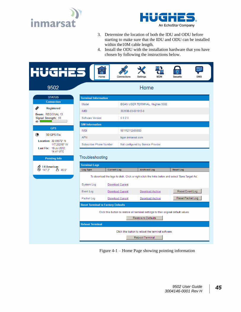
3. Determine the location of both the IDU and ODU before
starting to make sure that the IDU and ODU can be installed
within the10M cable length.
4. Install the ODU with the installation hardware that you have
chosen by following the instructions below.
Figure 4-1 – Home Page showing pointing information
46 9502 User Guide 3004146-0001 Rev H
ODU installation using the basic fix mount kit; (P/N 3004066-0002)
You may install the fixed mount on any structurally sound surface;
either on a horizontal, or vertical, or a sloped surface such as a roof
or wall.
1. The pole has a 1.66” (4.2164cm) outer diameter (schedule 40
metal).
2. The pole mount is 2lbs/0.9Kg. The azimuth/elevation bracket
is 1 lb/0.45Kg.
3. The wall mounting pattern has four bolts in a 6” x 3 ¾”
(15.24cm x 9.525cm) rectangle.
The pole is shipped attached to the base bracket. Mount the base
bracket of this assembly to the structure with the appropriate
hardware (not included). Consult local building codes if needed.
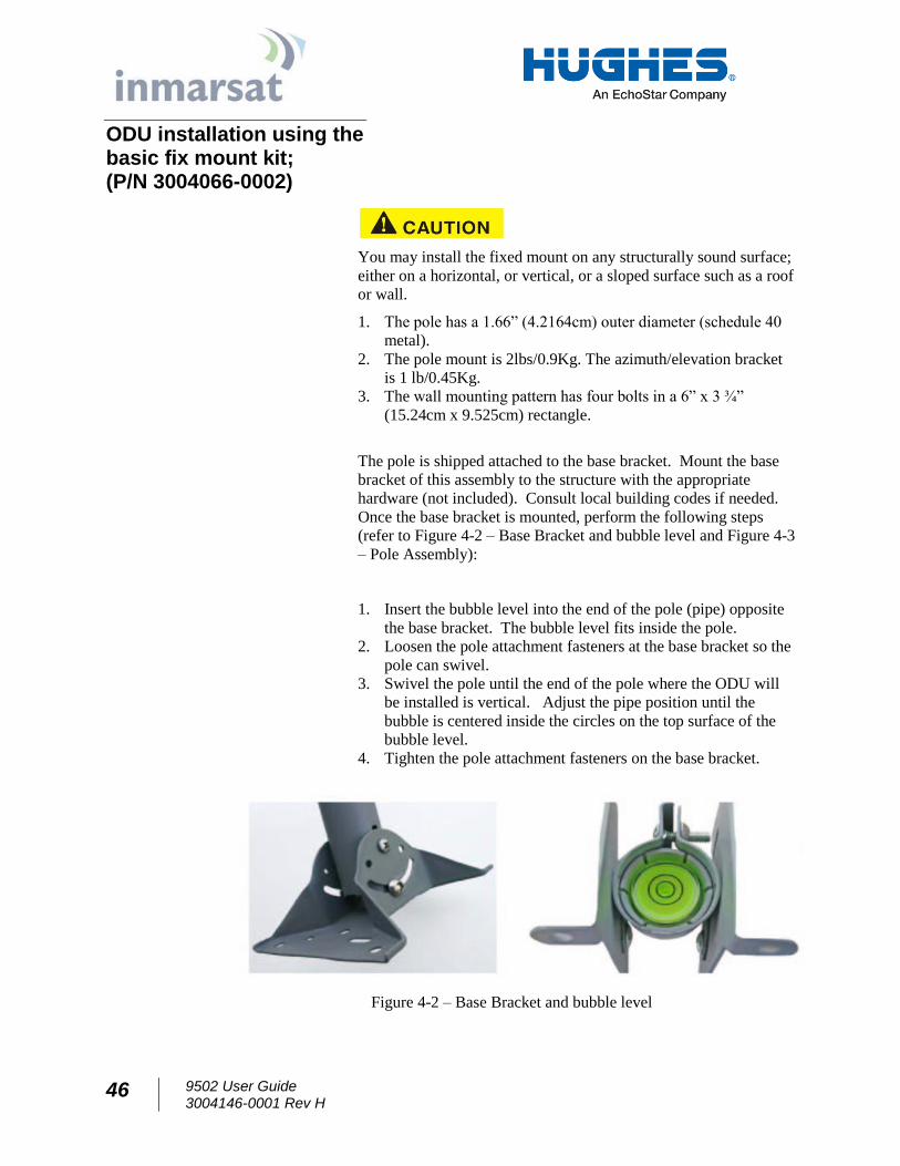
Once the base bracket is mounted, perform the following steps
(refer to Figure 4-2 – Base Bracket and bubble level and Figure 4-3
– Pole Assembly):
1. Insert the bubble level into the end of the pole (pipe) opposite
the base bracket. The bubble level fits inside the pole.
2. Loosen the pole attachment fasteners at the base bracket so the
pole can swivel.
3. Swivel the pole until the end of the pole where the ODU will
be installed is vertical. Adjust the pipe position until the
bubble is centered inside the circles on the top surface of the
bubble level.
4. Tighten the pole attachment fasteners on the base bracket.
Figure 4-2 – Base Bracket and bubble level
9502 User Guide 3004146-0001 Rev H
47
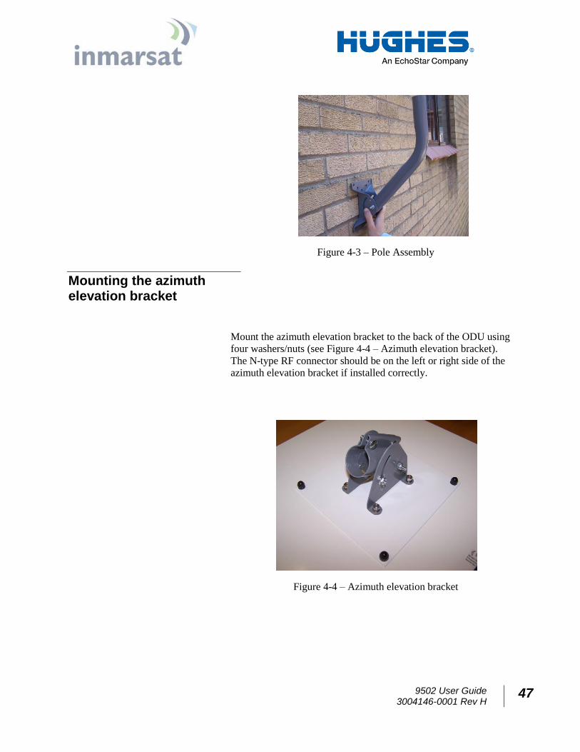
Figure 4-3 – Pole Assembly
Mounting the azimuth elevation bracket
Mount the azimuth elevation bracket to the back of the ODU using
four washers/nuts (see Figure 4-4 – Azimuth elevation bracket).
The N-type RF connector should be on the left or right side of the
azimuth elevation bracket if installed correctly.
Figure 4-4 – Azimuth elevation bracket
48 9502 User Guide 3004146-0001 Rev H
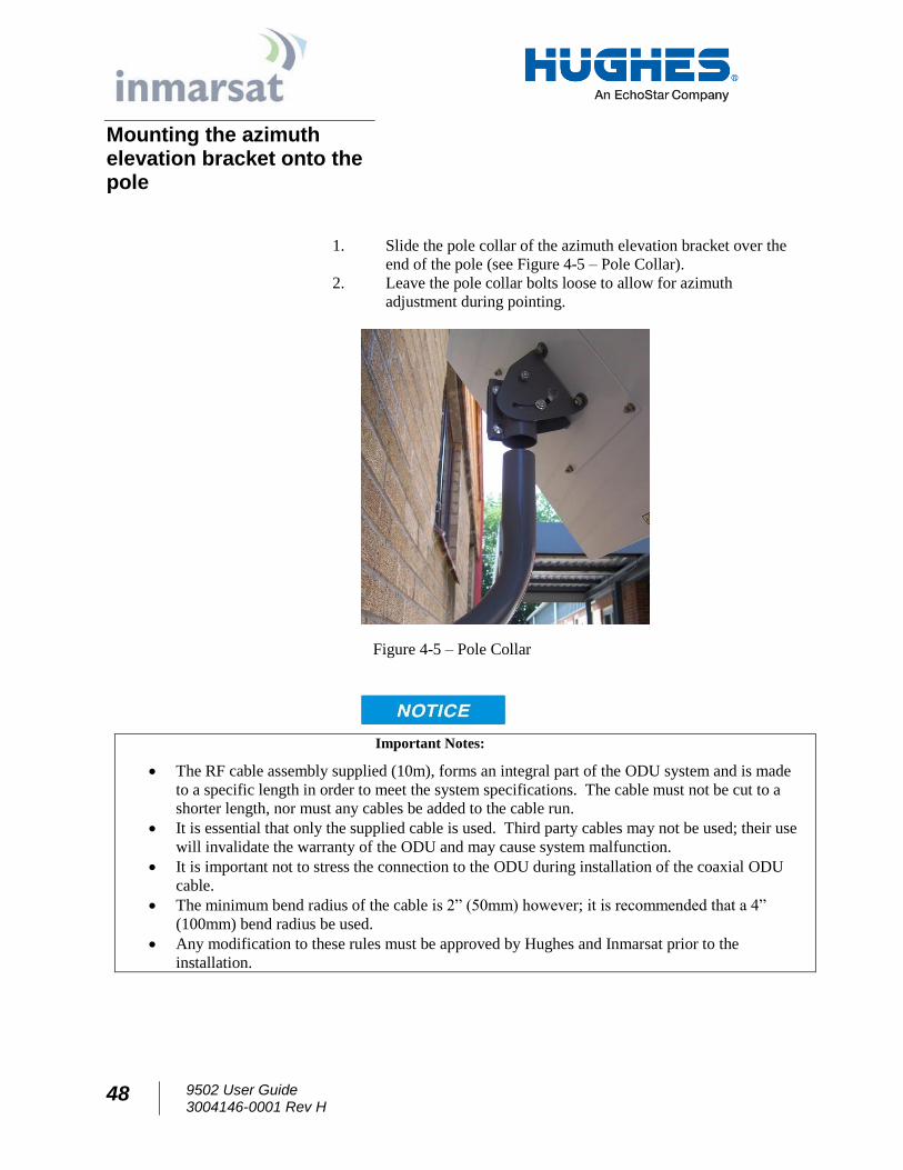
Mounting the azimuth elevation bracket onto the pole
1. Slide the pole collar of the azimuth elevation bracket over the
end of the pole (see Figure 4-5 – Pole Collar).
2. Leave the pole collar bolts loose to allow for azimuth
adjustment during pointing.
Figure 4-5 – Pole Collar
Important Notes:
The RF cable assembly supplied (10m), forms an integral part of the ODU system and is made
to a specific length in order to meet the system specifications. The cable must not be cut to a
shorter length, nor must any cables be added to the cable run.
It is essential that only the supplied cable is used. Third party cables may not be used; their use
will invalidate the warranty of the ODU and may cause system malfunction.
It is important not to stress the connection to the ODU during installation of the coaxial ODU
cable.
The minimum bend radius of the cable is 2” (50mm) however; it is recommended that a 4”
(100mm) bend radius be used.
Any modification to these rules must be approved by Hughes and Inmarsat prior to the
installation.
9502 User Guide 3004146-0001 Rev H
49
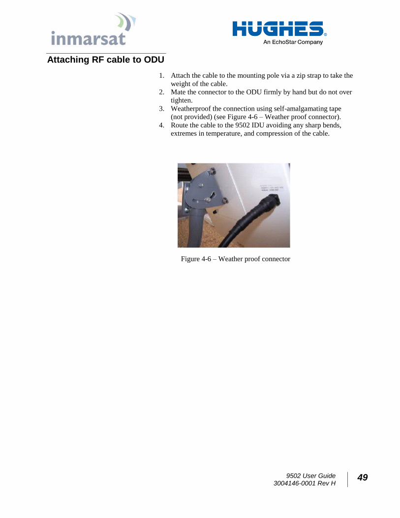
Attaching RF cable to ODU
1. Attach the cable to the mounting pole via a zip strap to take the
weight of the cable.
2. Mate the connector to the ODU firmly by hand but do not over
tighten.
3. Weatherproof the connection using self-amalgamating tape
(not provided) (see Figure 4-6 – Weather proof connector).
4. Route the cable to the 9502 IDU avoiding any sharp bends,
extremes in temperature, and compression of the cable.
Figure 4-6 – Weather proof connector
50 9502 User Guide 3004146-0001 Rev H
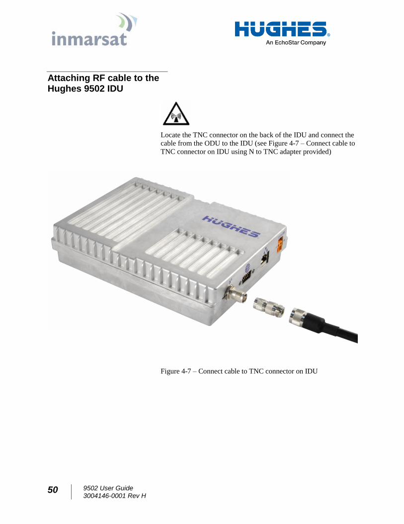
Attaching RF cable to the Hughes 9502 IDU
Locate the TNC connector on the back of the IDU and connect the
cable from the ODU to the IDU (see Figure 4-7 – Connect cable to
TNC connector on IDU using N to TNC adapter provided)
Figure 4-7 – Connect cable to TNC connector on IDU
9502 User Guide 3004146-0001 Rev H
51
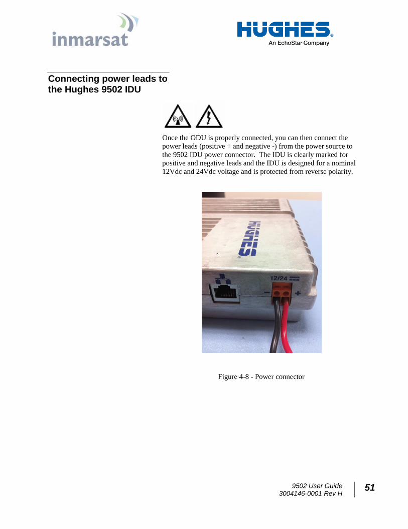
Connecting power leads to the Hughes 9502 IDU
Once the ODU is properly connected, you can then connect the
power leads (positive + and negative -) from the power source to
the 9502 IDU power connector. The IDU is clearly marked for
positive and negative leads and the IDU is designed for a nominal
12Vdc and 24Vdc voltage and is protected from reverse polarity.
Figure 4-8 - Power connector
52 9502 User Guide 3004146-0001 Rev H
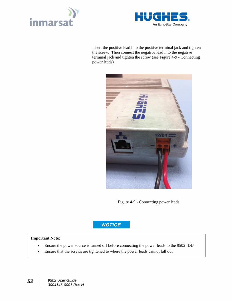
Insert the positive lead into the positive terminal jack and tighten
the screw. Then connect the negative lead into the negative
terminal jack and tighten the screw (see Figure 4-9 - Connecting
power leads).
Figure 4-9 - Connecting power leads
Important Note:
Ensure the power source is turned off before connecting the power leads to the 9502 IDU
Ensure that the screws are tightened to where the power leads cannot fall out
9502 User Guide 3004146-0001 Rev H
53
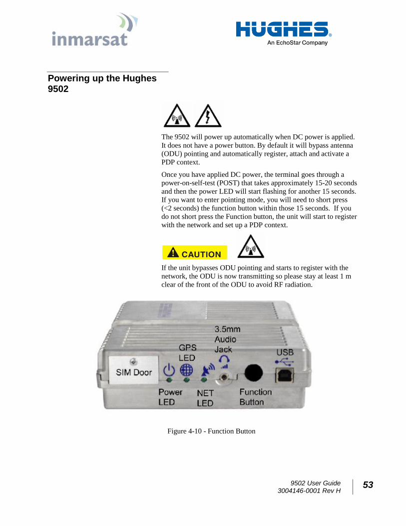
Powering up the Hughes 9502
The 9502 will power up automatically when DC power is applied.
It does not have a power button. By default it will bypass antenna
(ODU) pointing and automatically register, attach and activate a
PDP context.
Once you have applied DC power, the terminal goes through a
power-on-self-test (POST) that takes approximately 15-20 seconds
and then the power LED will start flashing for another 15 seconds.
If you want to enter pointing mode, you will need to short press
(<2 seconds) the function button within those 15 seconds. If you
do not short press the Function button, the unit will start to register
with the network and set up a PDP context.
If the unit bypasses ODU pointing and starts to register with the
network, the ODU is now transmitting so please stay at least 1 m
clear of the front of the ODU to avoid RF radiation.
Figure 4-10 - Function Button
54 9502 User Guide 3004146-0001 Rev H
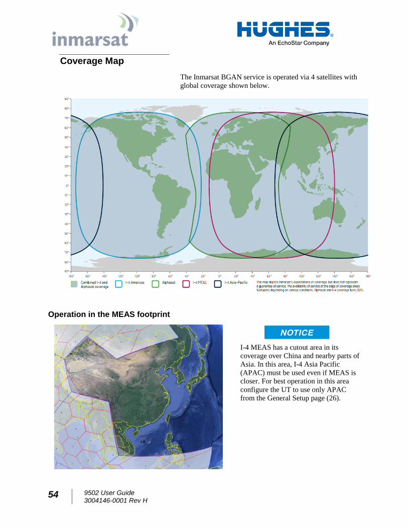
Coverage Map
The Inmarsat BGAN service is operated via 4 satellites with
global coverage shown below.
Operation in the MEAS footprint
I-4 MEAS has a cutout area in its
coverage over China and nearby parts of
Asia. In this area, I-4 Asia Pacific
(APAC) must be used even if MEAS is
closer. For best operation in this area
configure the UT to use only APAC
from the General Setup page (26).
9502 User Guide 3004146-0001 Rev H
55
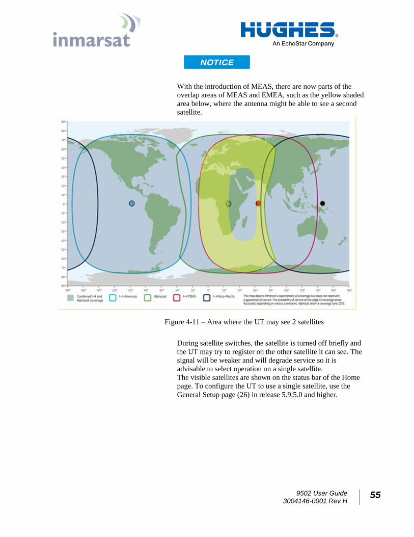
With the introduction of MEAS, there are now parts of the
overlap areas of MEAS and EMEA, such as the yellow shaded
area below, where the antenna might be able to see a second
satellite.
Figure 4-11 – Area where the UT may see 2 satellites
During satellite switches, the satellite is turned off briefly and
the UT may try to register on the other satellite it can see. The
signal will be weaker and will degrade service so it is
advisable to select operation on a single satellite. The visible satellites are shown on the status bar of the Home
page. To configure the UT to use a single satellite, use the
General Setup page (26) in release 5.9.5.0 and higher.
56 9502 User Guide 3004146-0001 Rev H
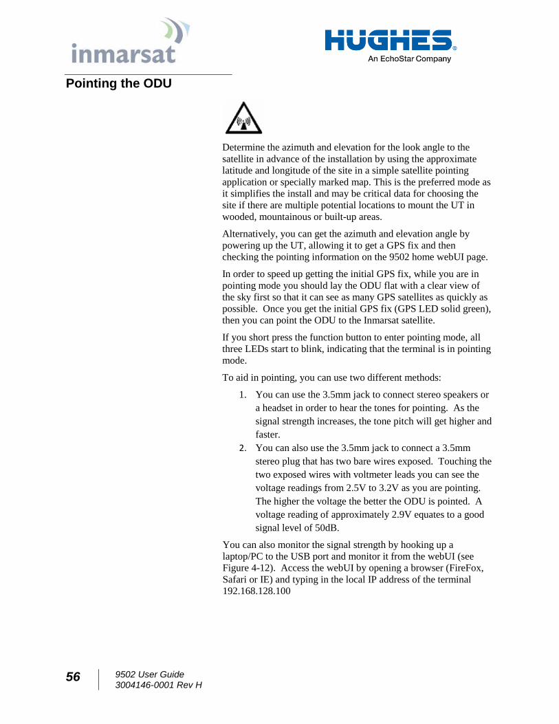
Pointing the ODU
Determine the azimuth and elevation for the look angle to the
satellite in advance of the installation by using the approximate
latitude and longitude of the site in a simple satellite pointing
application or specially marked map. This is the preferred mode as
it simplifies the install and may be critical data for choosing the
site if there are multiple potential locations to mount the UT in
wooded, mountainous or built-up areas.
Alternatively, you can get the azimuth and elevation angle by
powering up the UT, allowing it to get a GPS fix and then
checking the pointing information on the 9502 home webUI page.
In order to speed up getting the initial GPS fix, while you are in
pointing mode you should lay the ODU flat with a clear view of
the sky first so that it can see as many GPS satellites as quickly as
possible. Once you get the initial GPS fix (GPS LED solid green),
then you can point the ODU to the Inmarsat satellite.
If you short press the function button to enter pointing mode, all
three LEDs start to blink, indicating that the terminal is in pointing
mode.
To aid in pointing, you can use two different methods:
1. You can use the 3.5mm jack to connect stereo speakers or
a headset in order to hear the tones for pointing. As the
signal strength increases, the tone pitch will get higher and
faster.
2. You can also use the 3.5mm jack to connect a 3.5mm
stereo plug that has two bare wires exposed. Touching the
two exposed wires with voltmeter leads you can see the
voltage readings from 2.5V to 3.2V as you are pointing.
The higher the voltage the better the ODU is pointed. A
voltage reading of approximately 2.9V equates to a good
signal level of 50dB.
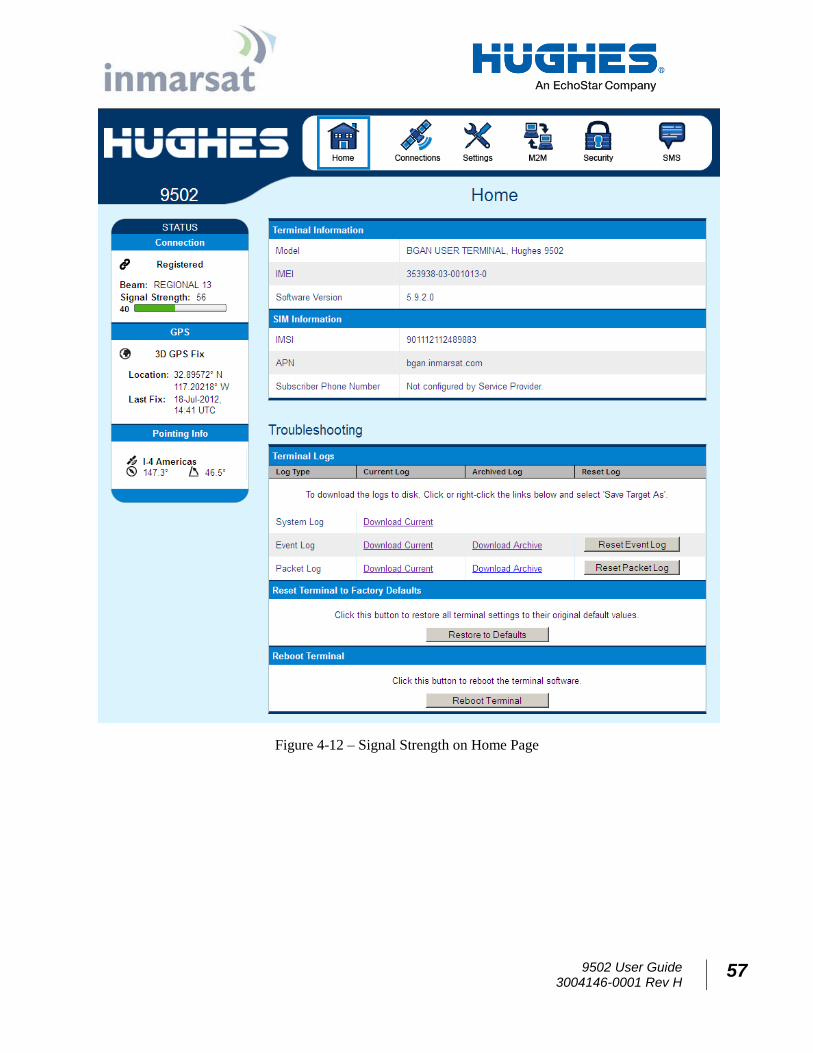
You can also monitor the signal strength by hooking up a
laptop/PC to the USB port and monitor it from the webUI (see
Figure 4-12). Access the webUI by opening a browser (FireFox,
Safari or IE) and typing in the local IP address of the terminal
192.168.128.100
9502 User Guide 3004146-0001 Rev H
57
Figure 4-12 – Signal Strength on Home Page
58 9502 User Guide 3004146-0001 Rev H
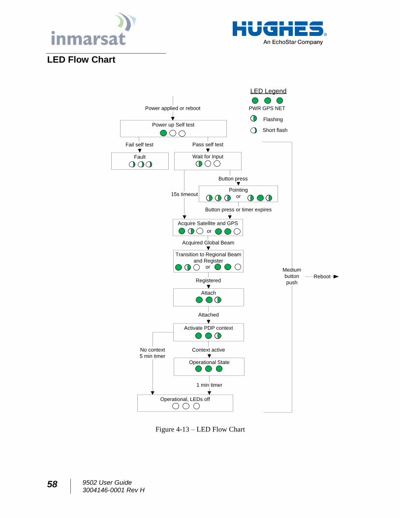
LED Flow Chart
Power up Self test
Attach
Activate PDP context
Attached
Operational State
Power applied or reboot
Pointing
or
Context active
Medium
button
pushReboot
Pass self test
Button press or timer expires
Transition to Regional Beam
and Register
Acquire Satellite and GPS
Registered
Acquired Global Beam
or
or
Fault
Fail self test
LED Legend
PWR GPS NET
Flashing
Short flash
Wait for Input
15s timeout
Operational, LEDs off
1 min timer
Button press
No context
5 min timer
Figure 4-13 – LED Flow Chart
9502 User Guide 3004146-0001 Rev H
59
Important Notes:
To aid in pointing the ODU, there is a 3.5mm stereo audio jack port on the IDU. The user can
insert a stereo headset to hear audio tones or use a voltmeter to measure the voltage which
indicates the quality of the signal detected during install mode.
The IDU must have DC power applied for pointing.
The GPS antenna is an integral part of the ODU and a GPS fix can be obtained as part of the
pointing process.
Once you are out of pointing mode, you need to stay away from the front and sides of the
ODU at least 1m for safety purposes.
60 9502 User Guide 3004146-0001 Rev H
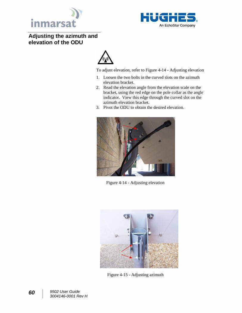
Adjusting the azimuth and elevation of the ODU
To adjust elevation, refer to Figure 4-14 - Adjusting elevation
1. Loosen the two bolts in the curved slots on the azimuth
elevation bracket.
2. Read the elevation angle from the elevation scale on the
bracket, using the red edge on the pole collar as the angle
indicator. View this edge through the curved slot on the
azimuth elevation bracket.
3. Pivot the ODU to obtain the desired elevation.
Figure 4-14 - Adjusting elevation
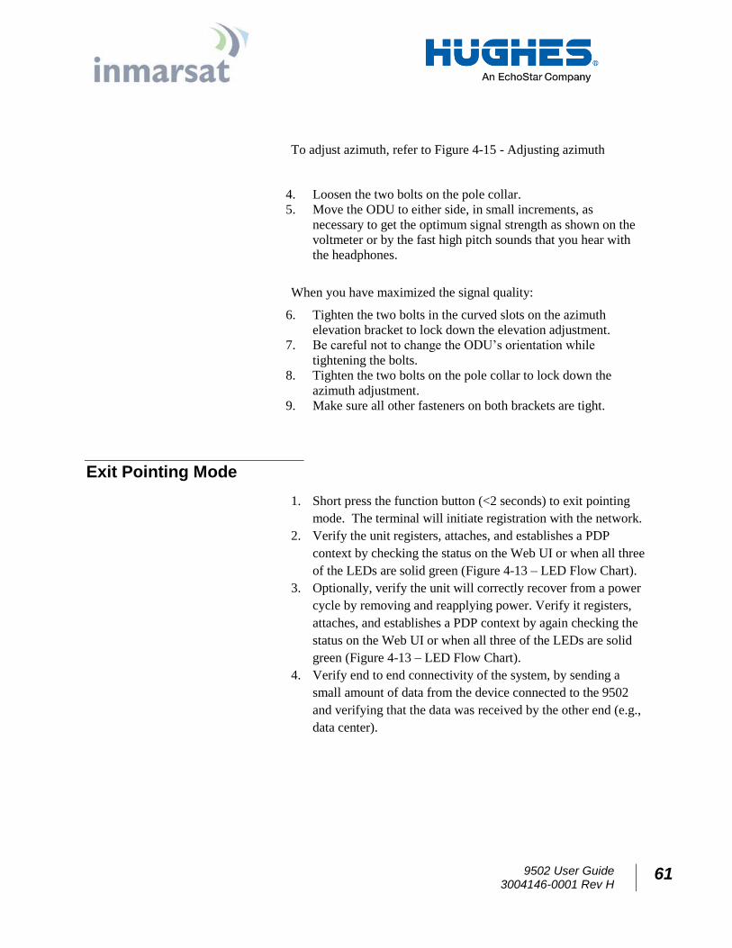
Figure 4-15 - Adjusting azimuth
9502 User Guide 3004146-0001 Rev H
61
To adjust azimuth, refer to Figure 4-15 - Adjusting azimuth
4. Loosen the two bolts on the pole collar.
5. Move the ODU to either side, in small increments, as
necessary to get the optimum signal strength as shown on the
voltmeter or by the fast high pitch sounds that you hear with
the headphones.
When you have maximized the signal quality:
6. Tighten the two bolts in the curved slots on the azimuth
elevation bracket to lock down the elevation adjustment.
7. Be careful not to change the ODU’s orientation while
tightening the bolts.
8. Tighten the two bolts on the pole collar to lock down the
azimuth adjustment.
9. Make sure all other fasteners on both brackets are tight.
Exit Pointing Mode
1. Short press the function button (<2 seconds) to exit pointing
mode. The terminal will initiate registration with the network.
2. Verify the unit registers, attaches, and establishes a PDP
context by checking the status on the Web UI or when all three
of the LEDs are solid green (Figure 4-13 – LED Flow Chart).
3. Optionally, verify the unit will correctly recover from a power
cycle by removing and reapplying power. Verify it registers,
attaches, and establishes a PDP context by again checking the
status on the Web UI or when all three of the LEDs are solid
green (Figure 4-13 – LED Flow Chart).
4. Verify end to end connectivity of the system, by sending a
small amount of data from the device connected to the 9502
and verifying that the data was received by the other end (e.g.,
data center).
62 9502 User Guide 3004146-0001 Rev H
Chapter 5 Lightning Protection and Safety
Lightning and Grounding Precautions / La foudre et la terre Précautions
A lightning strike on the ODU, mounting hardware or cable may
cause death or serious injury and is likely to damage both the ODU
and the IDU.
La foudre sur l'ODU, le matériel de montage ou les câbles peut
causer des blessures graves ou mortelles et est susceptible
d'endommager à la fois l'ODU et l’IDU.
It is therefore essential that the installer does not use an installation
location, which is likely to experience a lightning strike, and make
suitable grounding and lightning protection arrangements to
minimize any possibility of injury or damage. Professional local
advice should be sought with respect to these matters. Hughes
accepts no liability for any injury or damage caused by lightning
strikes.
Il est donc essentiel que l'installateur évite tout emplacement
d'installation susceptible d’être frappé par la foudre, et de
mettre en place un dispositif de mise à la terre et de protection
contre la foudre adapté afin de minimiser tout risque de
blessure ou de dommage. Un conseil professionnel local
devrait être consulté à cet égard . Hughes n'accepte aucune
responsabilité pour tout préjudice ou dommage causé par la
foudre.
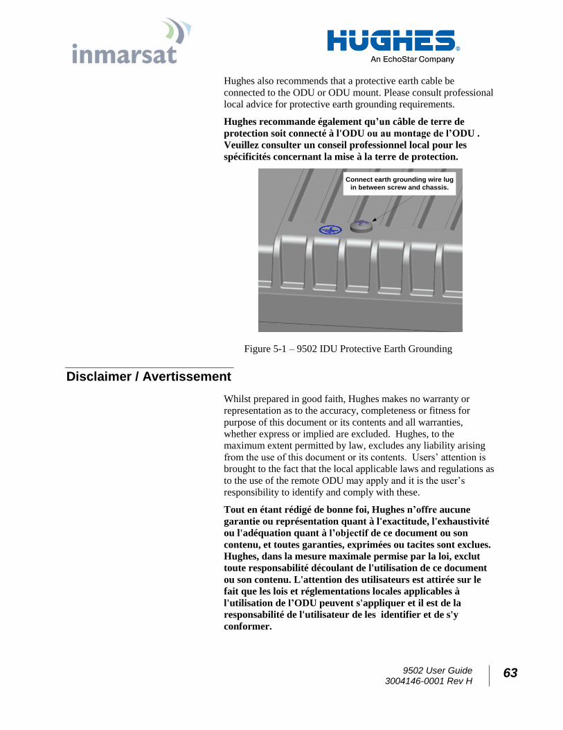
Hughes 9502 indoor unit (IDU) chassis shall be connected to earth
ground. Connect the earth grounding wire with lug in between the
ground screw and chassis. Tighten the ground screw after the wire
lug is installed. The wire lug material shall be either tin-plated
copper or tin-plated steel.
Le châssis de l’unité d’intérieur Hughes 9502 (IDU) doit être
connecté à la terre. Connectez le câble de mise à la terre avec
une cosse entre la vis de terre et le châssis. Serrez la vis de
terre après que le câble avec cosse ait été installé. Le câble avec
cosse doit être soit en cuivre zingué ou en acier étamé.
9502 User Guide 3004146-0001 Rev H
63
Hughes also recommends that a protective earth cable be
connected to the ODU or ODU mount. Please consult professional
local advice for protective earth grounding requirements.
Hughes recommande également qu’un câble de terre de
protection soit connecté à l'ODU ou au montage de l’ODU .
Veuillez consulter un conseil professionnel local pour les
spécificités concernant la mise à la terre de protection.
Connect earth grounding wire lug
in between screw and chassis.
Figure 5-1 – 9502 IDU Protective Earth Grounding
Disclaimer / Avertissement
Whilst prepared in good faith, Hughes makes no warranty or
representation as to the accuracy, completeness or fitness for
purpose of this document or its contents and all warranties,
whether express or implied are excluded. Hughes, to the
maximum extent permitted by law, excludes any liability arising
from the use of this document or its contents. Users’ attention is
brought to the fact that the local applicable laws and regulations as
to the use of the remote ODU may apply and it is the user’s
responsibility to identify and comply with these.
Tout en étant rédigé de bonne foi, Hughes n’offre aucune
garantie ou représentation quant à l'exactitude, l'exhaustivité
ou l'adéquation quant à l’objectif de ce document ou son
contenu, et toutes garanties, exprimées ou tacites sont exclues.
Hughes, dans la mesure maximale permise par la loi, exclut
toute responsabilité découlant de l'utilisation de ce document
ou son contenu. L'attention des utilisateurs est attirée sur le
fait que les lois et réglementations locales applicables à
l'utilisation de l’ODU peuvent s'appliquer et il est de la
responsabilité de l'utilisateur de les identifier et de s'y
conformer.
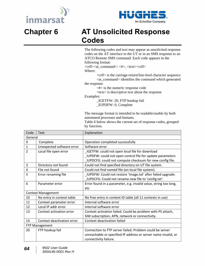
64 9502 User Guide 3004146-0001 Rev H
Chapter 6 AT Unsolicited Response Codes
The following codes and text may appear as unsolicited response
codes on the AT interface to the UT or in an SMS response to an
ATCO Remote SMS command. Each code appears in the
following format:
<crlf><at_command>: <#>, <text><crlf>
Where:
<crlf> is the carriage-return/line-feed character sequence
<at_command> identifies the command which generated
the response
<#> is the numeric response code
<text> is descriptive text about the response
Examples:
_IGETFW: 20, FTP hookup fail
_IUPDFW: 0, Complete
The message format is intended to be readable/usable by both
automated processes and humans. Table 6 below shows the current set of response codes, grouped
by function.
Code Text Explanation
General
0 Complete Operation completed successfully
1 Unexpected software error Software error
2 Local file open error _IGETFW: could not open local file for download _IUPDFW: could not open control file for update parameters _IUPDCFG: could not compute checksum for new config file.
3 Directory not found Could not find specified directory on UT file system.
4 File not found Could not find named file (on local file system).
5 Error renaming file _IUPDFW: Could not restore ‘image.txt’ after failed upgrade. _IUPDCFG: Could not rename new file to ‘config.txt’.
6 Parameter error Error found in a parameter, e.g. invalid value, string too long, etc
Context Management
10 No entry in context table No free entry in context ID table (all 11 contexts in use)
11 Context parameter error Internal software error
12 Local IP addr error Internal software error
13 Context activation error Context activation failed. Could be problem with PS attach, SIM subscription, APN, network or connectivity.
14 Context deactivation error Context deactivation failed
FTP Management
20 FTP hookup fail Connection to FTP server failed. Problem could be server unreachable or specified IP address or server name invalid, or connectivity failure.
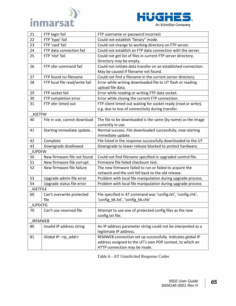
9502 User Guide 3004146-0001 Rev H
65
21 FTP login fail FTP username or password incorrect
22 FTP 'type' fail Could not establish “binary” mode.
23 FTP 'cwd' fail Could not change to working directory on FTP server.
24 FTP data connection fail Could not establish an FTP data connection with the server.
25 FTP 'nlst' fail Could not get list of files in current FTP server directory. Directory may be empty.
26 FTP xfer command fail Could not initiate data transfer on an established connection. May be caused if filename not found.
27 FTP found no filename Could not find a filename in the current server directory.
28 FTP local file read/write fail Error while writing downloaded file to UT flash or reading upload file data.
29 FTP socket fail Error while reading or writing FTP data socket.
30 FTP completion error Error while closing the current FTP connection.
31 FTP xfer timed out FTP client timed out waiting for socket ready (read or write), e.g. due to loss of connectivity during transfer.
_IGETFW
40 File in use, cannot download The file to be downloaded is the same (by name) as the image currently in use.
41 Starting immediate update… Normal success. File downloaded successfully, now starting immediate update.
42 Complete File listed in the response successfully downloaded to the UT
43 Downgrade disallowed Downgrade to lower release blocked to protect hardware.
_IUPDFW
50 New firmware file not found Could not find filename specified in upgraded control file.
51 New firmware file corrupt Firmware file failed checksum test.
52 New firmware file failure The new firmware failed to run or failed to acquire the network and the unit fell back to the old release.
53 Upgrade admin file error Problem with local file manipulation during upgrade process.
54 Upgrade status file error Problem with local file manipulation during upgrade process
_IGETFILE
60 Can't overwrite protected file
File specified in AT command was ‘config.txt’, ‘config.chk’, ‘config_bk.txt’, ‘config_bk.chk’
_IUPDCFG
70 Can't use reserved file Attempt to use one of protected config files as the new config.txt file.
_IREMWEB
80 Invalid IP address string An IP address parameter string could not be interpreted as a legitimate IP address.
81 Global IP: <ip_addr> REMWEB connection set up successfully. Indicates global IP address assigned to the UT’s own PDP context, to which an HTTP connection may be made.
Table 6 - AT Unsolicited Response Codes
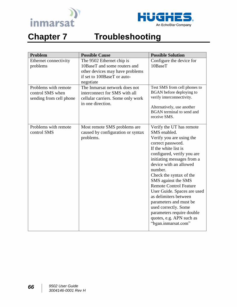
66 9502 User Guide 3004146-0001 Rev H
Chapter 7 Troubleshooting
Problem Possible Cause Possible Solution
Ethernet connectivity
problems
The 9502 Ethernet chip is
10BaseT and some routers and
other devices may have problems
if set to 100BaseT or auto-
negotiate
Configure the device for
10BaseT
Problems with remote
control SMS when
sending from cell phone
The Inmarsat network does not
interconnect for SMS with all
cellular carriers. Some only work
in one direction.
Test SMS from cell phones to
BGAN before deploying to
verify interconnectivity.
Alternatively, use another
BGAN terminal to send and
receive SMS.
Problems with remote
control SMS
Most remote SMS problems are
caused by configuration or syntax
problems.
Verify the UT has remote
SMS enabled.
Verify you are using the
correct password.
If the white list is
configured, verify you are
initiating messages from a
device with an allowed
number.
Check the syntax of the
SMS against the SMS
Remote Control Feature
User Guide. Spaces are used
as delimiters between
parameters and must be
used correctly. Some
parameters require double
quotes, e.g. APN such as
“bgan.inmarsat.com”
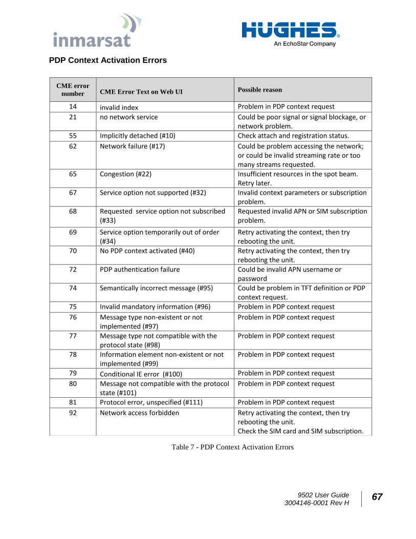
9502 User Guide 3004146-0001 Rev H
67
PDP Context Activation Errors
Table 7 - PDP Context Activation Errors
CME error
number CME Error Text on Web UI Possible reason
14 invalid index Problem in PDP context request
21 no network service
Could be poor signal or signal blockage, or network problem.
55 Implicitly detached (#10) Check attach and registration status.
62 Network failure (#17)
Could be problem accessing the network; or could be invalid streaming rate or too many streams requested.
65 Congestion (#22) Insufficient resources in the spot beam. Retry later.
67 Service option not supported (#32) Invalid context parameters or subscription problem.
68 Requested service option not subscribed (#33)
Requested invalid APN or SIM subscription problem.
69 Service option temporarily out of order (#34)
Retry activating the context, then try rebooting the unit.
70 No PDP context activated (#40) Retry activating the context, then try rebooting the unit.
72 PDP authentication failure Could be invalid APN username or password
74 Semantically incorrect message (#95) Could be problem in TFT definition or PDP context request.
75 Invalid mandatory information (#96) Problem in PDP context request
76 Message type non-existent or not implemented (#97)
Problem in PDP context request
77 Message type not compatible with the protocol state (#98)
Problem in PDP context request
78 Information element non-existent or not implemented (#99)
Problem in PDP context request
79 Conditional IE error (#100) Problem in PDP context request
80 Message not compatible with the protocol state (#101)
Problem in PDP context request
81 Protocol error, unspecified (#111) Problem in PDP context request
92 Network access forbidden Retry activating the context, then try rebooting the unit. Check the SIM card and SIM subscription.
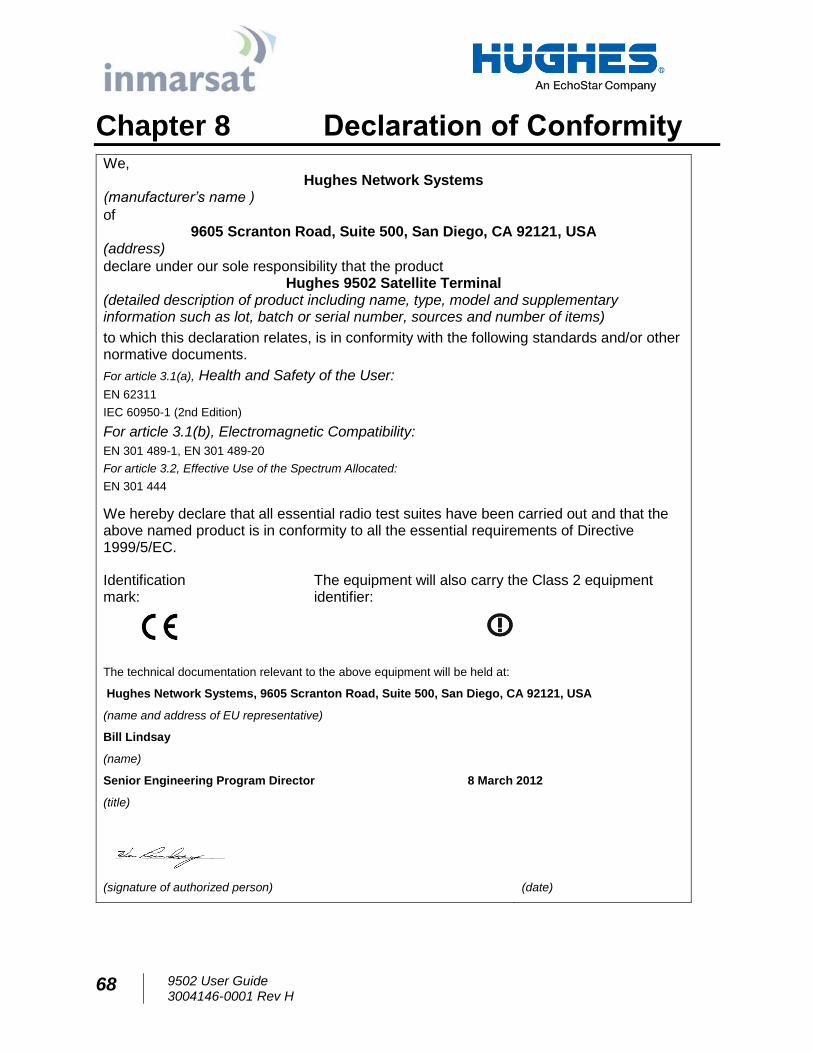
68 9502 User Guide 3004146-0001 Rev H
Chapter 8 Declaration of Conformity We,
Hughes Network Systems (manufacturer’s name )
of 9605 Scranton Road, Suite 500, San Diego, CA 92121, USA
(address)
declare under our sole responsibility that the product Hughes 9502 Satellite Terminal
(detailed description of product including name, type, model and supplementary information such as lot, batch or serial number, sources and number of items)
to which this declaration relates, is in conformity with the following standards and/or other normative documents.
For article 3.1(a), Health and Safety of the User:
EN 62311
IEC 60950-1 (2nd Edition)
For article 3.1(b), Electromagnetic Compatibility:
EN 301 489-1, EN 301 489-20
For article 3.2, Effective Use of the Spectrum Allocated:
EN 301 444
We hereby declare that all essential radio test suites have been carried out and that the above named product is in conformity to all the essential requirements of Directive 1999/5/EC.
Identification mark:
The equipment will also carry the Class 2 equipment identifier:
The technical documentation relevant to the above equipment will be held at:
Hughes Network Systems, 9605 Scranton Road, Suite 500, San Diego, CA 92121, USA
(name and address of EU representative)
Bill Lindsay
(name)
Senior Engineering Program Director 8 March 2012
(title)
(signature of authorized person) (date)
9502 User Guide 3004146-0001 Rev H
69
FCC Compliance / Conformité FCC
This device conforms to the FCC rules. Any changes or
modifications to Hughes Network Systems’ equipment, not
expressly approved by Hughes Network Systems, could void the
user's authority to operate the equipment.
Cet appareil est conforme aux règles FCC. Toute modification
apportée à l’équipement de Hughes Network Systems et non
approuvé expressément par Hughes Network Systems, peut
annuler l’autorisation de l’utilisateur à opérer
cet équipement.
To comply with FCC RF exposure requirements, this device must
be operated with a minimum separation distance of one meter from
the front of the satellite terminal’s antenna to a person's body.
Other operating configurations should be avoided.
Afin d’être conforme aux exigences FCC concernant
l’exposition RF, cet appareil doit être utilisé tout en
maintenant une distance de séparation minimale d’un mètre
entre la personne et le devant de l’antenne du terminal
satellite. Toute autre configuration d’utilisation doit être
évitée.
This device complies with Part 15 of the FCC Rules. Operation is
subject to the following two conditions; (1) this device may not
cause harmful interference, and (2) this device must accept any
interference received, including interference that may cause
undesired operation.
Cet appareil est conforme à la Section 15 du règlement FCC.
Son fonctionnement est sujet aux deux conditions suivantes ;
(1) ce matériel ne peut pas provoquer d’interférences nuisibles,
et (2) ce matériel doit pouvoir tolérer n’importe quelle
interférence reçue, y compris les interférences qui peuvent
provoquer un fonctionnement indésirable.
IC Compliance / Conformité IC
This device conforms to Industry Canada's rules. Any changes to
Hughes Network Systems' equipment, not expressly approved by
Hughes Network Systems, could void the user's authority to
operate the equipment.
Cet appareil est conforme aux règlements de l’Industrie
Canada. Tout changement à l’équipement de Hughes Network
Systems, sans le consentement exprès de Hughes Network
Systems, peut résulter à l’annulation de l’autorité confiée à
l’usager d’opérer cet équipement.
70 9502 User Guide 3004146-0001 Rev H
To comply with Industry Canada's RF exposure requirements, this
device must be operated with a minimum separation distance of
one meter from the satellite terminal's antenna to a person's body.
Other operating configurations should be avoided.
Pour être conforme aux règlements d’Industrie Canada sur
l’exposition aux rayonnements RF, cet appareil se doit opérer à
une distance d’au moins un mètre entre l’antenne du terminal
de transmission satellite et le corps d’une personne. Toute
autre configuration d’opération devrait être évitée.
EU RoHS (Restriction of Hazardous Substances) Directive
The European Union (EU) Directive 2011/65/EU restricts the use
of certain hazardous substances in electrical and electronic
equipment.
Unless otherwise noted, all products, assemblies, and sub-
assemblies manufactured by Hughes and its sub-contractors are
compliant with this directive.
EU WEEE (Waste Electrical and Electronic Equipment) Directives
The European Union (EU) Directive 2002/96/EC on waste
electrical and electronic equipment mandate recycling of electrical
and electronic equipment throughout the EU by August 13, 2005.
Unless otherwise noted, all products, assemblies, and sub-
assemblies manufactured by Hughes and its sub-contractors are
compliant with this directive and any subsequent revisions or
amendments. This product carries the WEEE label below to
demonstrate compliance.
For addition information, contact Hughes Network Systems at:
www.hughes.com.