human landing system (hls) ascent element (ae) lunar crew
TRANSCRIPT
1
Human Landing System (HLS) Ascent Element (AE) Lunar Crew Module (LCM) Technology Opportunities Selected Opportunities, Capabilities, Benefits and Needs Applicable to the HLS BAA Appendix H for an Integrated Lander 03 July 2019 NASA Points of Contact (POC) at the Johnson Space Center (JSC):
• [email protected], JSC Lander Project Manager, HLS AE/LCM Lead • [email protected], JSC Exploration Technology Office Manager
Table of Contents
1.0 CORE FLIGHT SOFTWARE (CFS) 2
2.0 AES MODULE POWER SYSTEM (AMPS) 11
3.0 DOCKING SYSTEMS 16
4.0 OPTICAL NAVIGATION (OP-NAV) 23
5.0 SPACESUIT WATER MEMBRANE EVAPORATOR (SWME) 24
2
1.0 CORE FLIGHT SOFTWARE (CFS) CFS is an open-source software framework and asset for Flight Software Reuse.
NASA POC and TechPort link:
• [email protected], PhD, LCM FSW Lead at JSC • https://techport.nasa.gov/view/11771
1.1 CFS OVERVIEW The Core Flight Software (CFS) framework is an open-source TRL-9 and human-rated NASA Agency asset designed from the ground up for flight software reuse. It is used within the government as well as by commercial companies, international partners, and within academia, and has a scalable applicability to real-time space systems. The CFS provides a component-based architecture, platform and operating system independence, a host of communication and common services, as well as data-driven/reusable applications enabling increased productivity, interoperability with other modules/elements, human certification, and rapid access to space.
1.2 BACKGROUND The Core Flight Software (CFS) Framework is an open-source product originally developed by NASA Goddard Space Flight Center (GSFC) and first flown in 2009 with the Lunar Reconnaissance orbiter (LRO) mission. The genesis of the development was based on the need to “not reinvent the wheel” for every spacecraft and for a reusable, configurable, platform agnostic, and componentized software package representing a low common denominator for flight software. Since then, through grass roots efforts at multiple NASA centers and Agency-level funding, the CFS has since matured and been productized into a suite of open-source and government-release software products/tools, and its use has expanded throughout NASA, commercial and international partners, and academia.
A feasibility assessment completed in 2012 showed scalability and broad applicability to a variety of avionics and software architectures as well as design for human rating. It has been used in partitioned, distributed, and redundant systems, and was first certified for human rating in 2014. Some notable projects employing the CFS are Orion Ascent Abort 2 (AA-2-2019), Morpheus Lander (2012), Orion Backup Flight Software (BFS-2020), Lunar Atmosphere and Dust Environment Explorer (LADEE-2013), and Solar Probe Plus (SPP-2018).
1.3 BENEFITS Benefits of CFS are realized in increased software productivity, reduced testing time, and increased reliability through maturity. Some specific benefits include the following:
• Increased Productivity – Starting with an architecture, reusable applications, and a design from which to “plug in” applications (apps), projects are able to focus on their mission specifics rather than reinvent common functions, and “hit the
3
ground running” with their particular needs. Typical projects define their apps quickly and are able to “divide and conquer” the development effort across developers
• Maturity and Stability – The CFS framework is TRL-9, has a large community of practice for support, and the framework API has been stable for many years. It includes detailed documentation, development artifacts, and a test suite for platform certification.
• Platform Independence – Abstraction layers allow the development team to develop on common systems such as Linux and deploy on a number of common operating systems and processor architectures
• Data-Driven Design – A data-driven architecture allows for dynamic reconfiguration and adaptation to different modes, situations, and states without change software source code
• Interoperability – CFS framework can be considered a software protocol, built on the underlying CCSDS standard and providing a common method for command, telemetry, communications, control, events across a distributed network, so is adaptable to spacecraft constellations
• Supporting Products – Many reusable applications and support tools are available for software lifecycle issues such as ground data reconfiguration and testing/certification
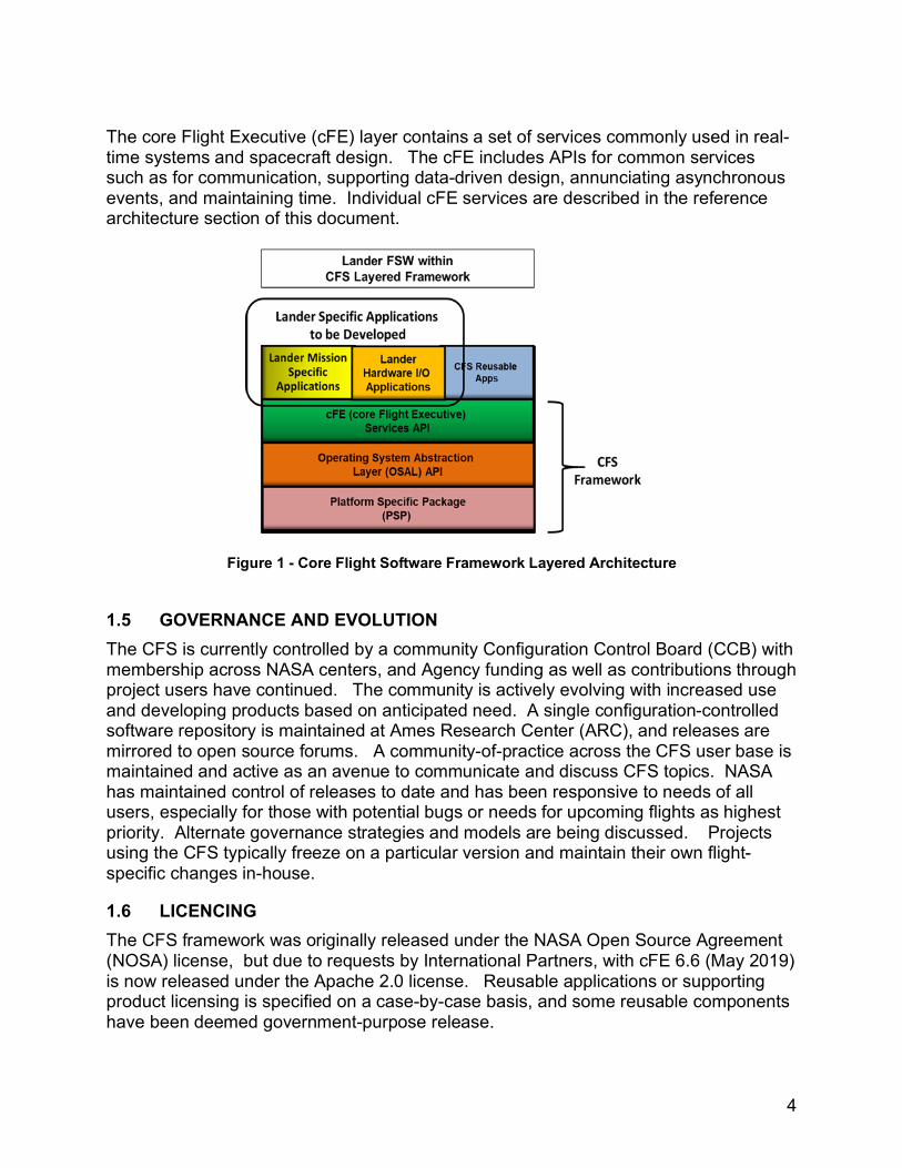
1.4 CFS LAYERED ARCHITECTURE The CFS framework itself is a lightweight, layered architecture as shown in the following figure. Each of the bottom three layers provide a stable Application Program Interface (API) for adapting to particular operating systems, hardware, providing common services, and to allow applications to “plug in” to the framework.
The bottom two layers of the framework provide operating system and platform independence. The Platform Support Package (PSP) layer provides access to the processor architecture and platform interfaces. Many PSPs have been developed and are available for cFS support on a specific hardware platform. Some examples of PSP layers include the Sparc, PowerPC, ARM, and Pentium architectures, among others. The user chooses a PSP, or set of PSPs for a distributed heterogeneous system to use for a particular mission. Similarly, the Operating System Abstraction Layer (OSAL) layer is a POSIX-like API that maps to several common flight software operating systems. Several OSAL layers exist from which to choose, including support for RTEMS, VxWorks, Integrity, and Linux. The user may develop cFS applications using an operating system such as Linux on a desktop Intel platform long before the hardware platforms are available, then build for a target system such as VxWorks on a PowerPC, with no change to application source code.
4
The core Flight Executive (cFE) layer contains a set of services commonly used in real-time systems and spacecraft design. The cFE includes APIs for common services such as for communication, supporting data-driven design, annunciating asynchronous events, and maintaining time. Individual cFE services are described in the reference architecture section of this document.
Figure 1 - Core Flight Software Framework Layered Architecture
1.5 GOVERNANCE AND EVOLUTION The CFS is currently controlled by a community Configuration Control Board (CCB) with membership across NASA centers, and Agency funding as well as contributions through project users have continued. The community is actively evolving with increased use and developing products based on anticipated need. A single configuration-controlled software repository is maintained at Ames Research Center (ARC), and releases are mirrored to open source forums. A community-of-practice across the CFS user base is maintained and active as an avenue to communicate and discuss CFS topics. NASA has maintained control of releases to date and has been responsive to needs of all users, especially for those with potential bugs or needs for upcoming flights as highest priority. Alternate governance strategies and models are being discussed. Projects using the CFS typically freeze on a particular version and maintain their own flight-specific changes in-house.
1.6 LICENCING The CFS framework was originally released under the NASA Open Source Agreement (NOSA) license, but due to requests by International Partners, with cFE 6.6 (May 2019) is now released under the Apache 2.0 license. Reusable applications or supporting product licensing is specified on a case-by-case basis, and some reusable components have been deemed government-purpose release.
5
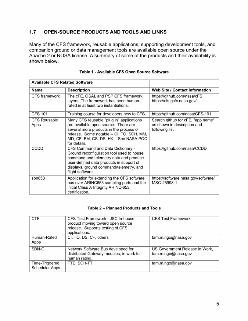
1.7 OPEN-SOURCE PRODUCTS AND TOOLS AND LINKS Many of the CFS framework, reusable applications, supporting development tools, and companion ground or data management tools are available open source under the Apache 2 or NOSA license. A summary of some of the products and their availability is shown below.
Table 1 - Available CFS Open Source Software
Available CFS Related Software
Name Description Web Site / Contact Information CFS framework The cFE, OSAL and PSP CFS framework
layers. The framework has been human-rated in at least two instantiations.
https://github.com/nasa/cFS https://cfs.gsfc.nasa.gov/
CFS 101 Training course for developers new to CFS. https://github.com/nasa/CFS-101 CFS Reusable Apps
Many CFS reusable "plug in" applications are available open source. There are several more products in the process of release. Some notable -- CI, TO, SCH, MM, MD, CF, FM, CS, DS, HK. See NASA POC for details.
Search github for cFE, "app name" as shown in description and following list
CCDD CFS Command and Data Dictionary - Ground reconfiguration tool used to house command and telemetry data and produce user-defined data products in support of displays, ground command/telemetry, and flight software.
https://github.com/nasa/CCDD
sbn653 Application for extending the CFS software bus over ARINC653 sampling ports and the initial Class A Integrity ARINC-653 certification.
https://software.nasa.gov/software/MSC-25998-1
Table 2 – Planned Products and Tools
CTF CFS Test Framework - JSC In-house product moving toward open source release. Supports testing of CFS applications.
CFS Test Framework
Human-Rated Apps
CI, TO, DS, CF, others [email protected]
SBN-G Network Software Bus developed for distributed Gateway modules, in work for human rating.
US Government Release in Work, [email protected]
Time-Triggered Scheduler Apps
TTE, SCH-TT [email protected]
6
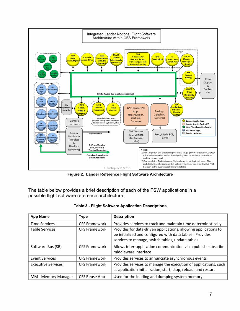
1.8 NOTIONAL LANDER FLIGHT SOFTWARE REFERENCE ARCHITECTURE In an effort to aid in understanding how the CFS framework operations and may be deployed to a spacecraft such as the Integrated Lander, a reference architecture based on the CFS is presented. The Integrated Lander reference architecture employs the CFS framework and utilizes reuse as much as possible, thus reducing the flight software development effort to only Integrated Lander mission specific applications. Flight software for the Integrated Lander must provide command, control, and monitoring of vehicle systems to achieve mission parameters outlined in the concept of operations. It provides support for all mission phases including, but not limited to, Gateway approach, rendezvous and docking, quiescent operations, undocking, descent, landing, surface operations, and ascent. It must provide for both uncrewed and crewed operations, providing ground command and control and automated mission sequences while uncrewed as well as manual piloting and human-in-the-loop interaction while crewed. The diagram below depicts a notional Integrated Lander flight software reference architecture utilizing the CFS framework. It consists of a collection of applications within the event-driven CFS framework. Applications communicate using messages sent/received on the Software Bus (SB). The applications are described individually in the table below. For simplicity, this particular diagram shows single processor instantiation, but it is equally possible to distribute these applications between cores, processors, or partitions. Each application executes at a pre-determined cyclic rate by being “awoken” by the scheduler (SCH) application. In real time, each application operates in a similar fashion - upon processor start, the application initializes with its configuration data. Subsequently, the application cyclically waits for a “wakeup” message, and then performs an “input-process-output” cycle. Each application is subscribed to messages on the CFS software bus. When it is awoken, it checks the mode (as set by Lander Executive – LEX), reads pending input messages and commands, performs its computation, publishes output, and then waits for next wake up message. Although each application is awoken at a cyclic rate, depending on the mode the vehicle is in, it may just send a heartbeat and wait for the next message rather than performing any computation. The applications “apps” in yellow and pink in the diagram are those that are uniquely built for the lander. The blue and green applications are reusable and are NASA-provided through open-source or US government-purpose.
7
Figure 2. Lander Reference Flight Software Architecture
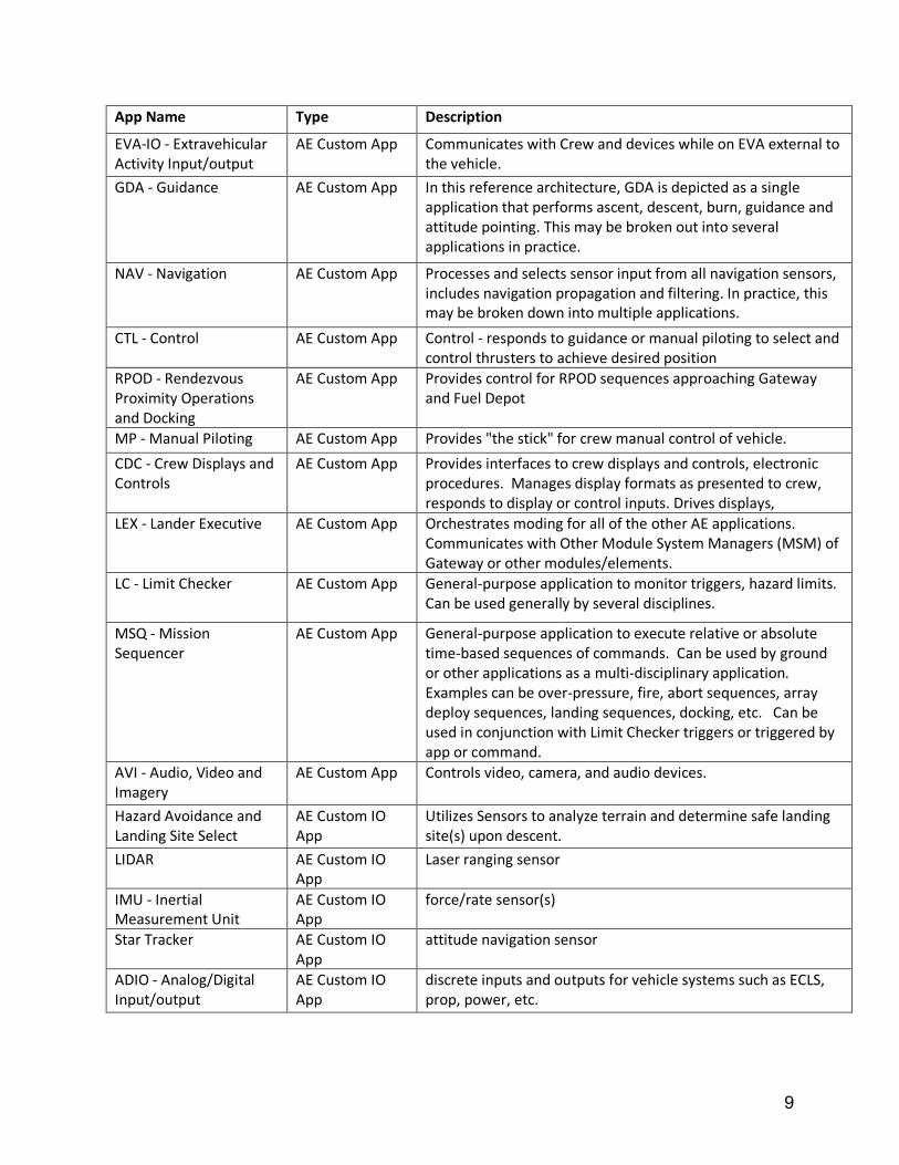
The table below provides a brief description of each of the FSW applications in a possible flight software reference architecture.
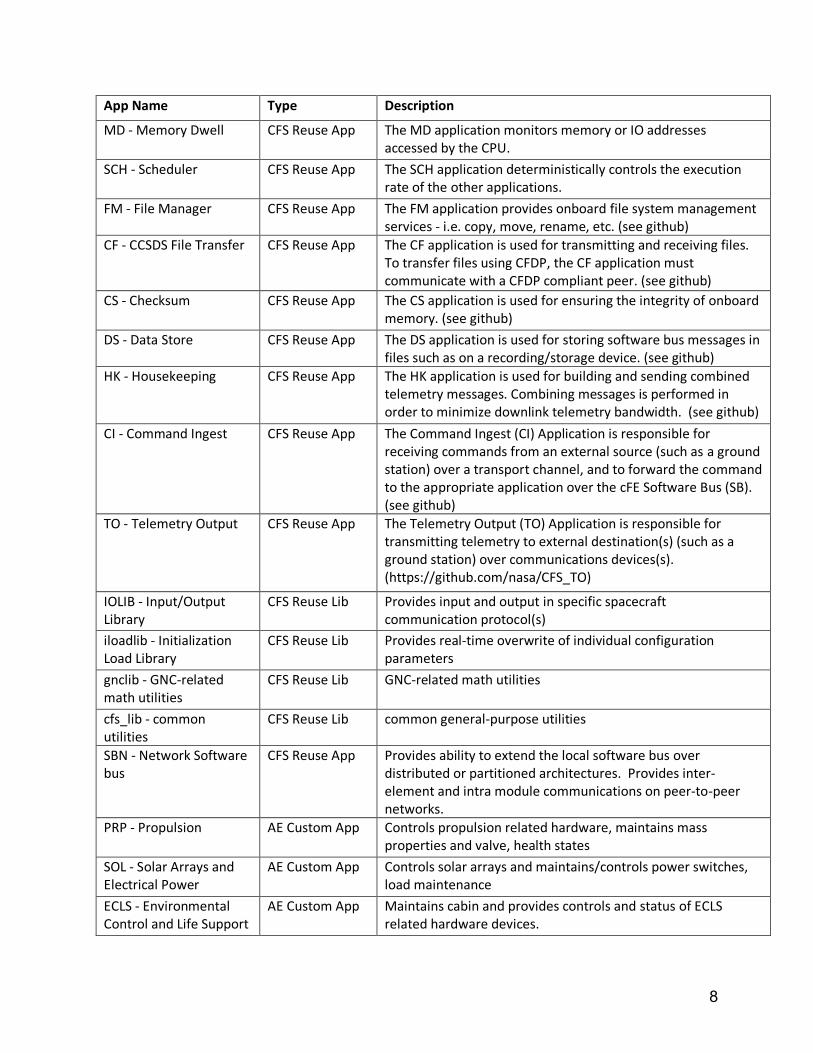
Table 3 - Flight Software Application Descriptions
App Name Type Description
Time Services CFS Framework Provides services to track and maintain time deterministically Table Services CFS Framework Provides for data-driven applications, allowing applications to
be initialized and configured with data tables. Provides services to manage, switch tables, update tables
Software Bus (SB) CFS Framework Allows inter-application communication via a publish-subscribe middleware interface
Event Services CFS Framework Provides services to annunciate asynchronous events Executive Services CFS Framework Provides services to manage the execution of applications, such
as application initialization, start, stop, reload, and restart
MM - Memory Manager CFS Reuse App Used for the loading and dumping system memory.
8
App Name Type Description
MD - Memory Dwell CFS Reuse App The MD application monitors memory or IO addresses accessed by the CPU.
SCH - Scheduler CFS Reuse App The SCH application deterministically controls the execution rate of the other applications.
FM - File Manager CFS Reuse App The FM application provides onboard file system management services - i.e. copy, move, rename, etc. (see github)
CF - CCSDS File Transfer CFS Reuse App The CF application is used for transmitting and receiving files. To transfer files using CFDP, the CF application must communicate with a CFDP compliant peer. (see github)
CS - Checksum CFS Reuse App The CS application is used for ensuring the integrity of onboard memory. (see github)
DS - Data Store CFS Reuse App The DS application is used for storing software bus messages in files such as on a recording/storage device. (see github)
HK - Housekeeping CFS Reuse App The HK application is used for building and sending combined telemetry messages. Combining messages is performed in order to minimize downlink telemetry bandwidth. (see github)
CI - Command Ingest CFS Reuse App The Command Ingest (CI) Application is responsible for receiving commands from an external source (such as a ground station) over a transport channel, and to forward the command to the appropriate application over the cFE Software Bus (SB). (see github)
TO - Telemetry Output CFS Reuse App The Telemetry Output (TO) Application is responsible for transmitting telemetry to external destination(s) (such as a ground station) over communications devices(s). (https://github.com/nasa/CFS_TO)
IOLIB - Input/Output Library
CFS Reuse Lib Provides input and output in specific spacecraft communication protocol(s)
iloadlib - Initialization Load Library
CFS Reuse Lib Provides real-time overwrite of individual configuration parameters
gnclib - GNC-related math utilities
CFS Reuse Lib GNC-related math utilities
cfs_lib - common utilities
CFS Reuse Lib common general-purpose utilities
SBN - Network Software bus
CFS Reuse App Provides ability to extend the local software bus over distributed or partitioned architectures. Provides inter-element and intra module communications on peer-to-peer networks.
PRP - Propulsion AE Custom App Controls propulsion related hardware, maintains mass properties and valve, health states
SOL - Solar Arrays and Electrical Power
AE Custom App Controls solar arrays and maintains/controls power switches, load maintenance
ECLS - Environmental Control and Life Support
AE Custom App Maintains cabin and provides controls and status of ECLS related hardware devices.
9
App Name Type Description
EVA-IO - Extravehicular Activity Input/output
AE Custom App Communicates with Crew and devices while on EVA external to the vehicle.
GDA - Guidance AE Custom App In this reference architecture, GDA is depicted as a single application that performs ascent, descent, burn, guidance and attitude pointing. This may be broken out into several applications in practice.
NAV - Navigation AE Custom App Processes and selects sensor input from all navigation sensors, includes navigation propagation and filtering. In practice, this may be broken down into multiple applications.
CTL - Control AE Custom App Control - responds to guidance or manual piloting to select and control thrusters to achieve desired position
RPOD - Rendezvous Proximity Operations and Docking
AE Custom App Provides control for RPOD sequences approaching Gateway and Fuel Depot
MP - Manual Piloting AE Custom App Provides "the stick" for crew manual control of vehicle. CDC - Crew Displays and Controls
AE Custom App Provides interfaces to crew displays and controls, electronic procedures. Manages display formats as presented to crew, responds to display or control inputs. Drives displays,
LEX - Lander Executive AE Custom App Orchestrates moding for all of the other AE applications. Communicates with Other Module System Managers (MSM) of Gateway or other modules/elements.
LC - Limit Checker AE Custom App General-purpose application to monitor triggers, hazard limits. Can be used generally by several disciplines.
MSQ - Mission Sequencer
AE Custom App General-purpose application to execute relative or absolute time-based sequences of commands. Can be used by ground or other applications as a multi-disciplinary application. Examples can be over-pressure, fire, abort sequences, array deploy sequences, landing sequences, docking, etc. Can be used in conjunction with Limit Checker triggers or triggered by app or command.
AVI - Audio, Video and Imagery
AE Custom App Controls video, camera, and audio devices.
Hazard Avoidance and Landing Site Select
AE Custom IO App
Utilizes Sensors to analyze terrain and determine safe landing site(s) upon descent.
LIDAR AE Custom IO App
Laser ranging sensor
IMU - Inertial Measurement Unit
AE Custom IO App
force/rate sensor(s)
Star Tracker AE Custom IO App
attitude navigation sensor
ADIO - Analog/Digital Input/output
AE Custom IO App
discrete inputs and outputs for vehicle systems such as ECLS, prop, power, etc.
10
1.9 AVIONICS ARCHITECTURE AND REDUNDANCY For simplicity, the software reference architecture shown above depicts a single processor instantiation; however, it is equally possible to distribute these applications between cores, processors, or partitions, and to adapt to a voting or hot-backup redundancy scheme. In a distributed system, the SBN application may be used to extend the software bus to other processors. In a multi-core system, the multi-core OSAL layer can be used to distribute processing across cores. Additionally, the CFS framework has been certified within an ARINC-653 partitioned environment, where a CFS instantiation is housed within one or more partitions extending the software bus over sampling ports. In a voting environment or time-triggered network environment, special voting and synchronization applications have been developed and are available for reuse. Feasibility of the CFS framework to scale and fit within these alternate avionics architectures has been shown. It is assumed that there will be some replication of the flight software for redundancy in a human lander system. In addition, a dissimilar, smaller backup flight system is anticipated.
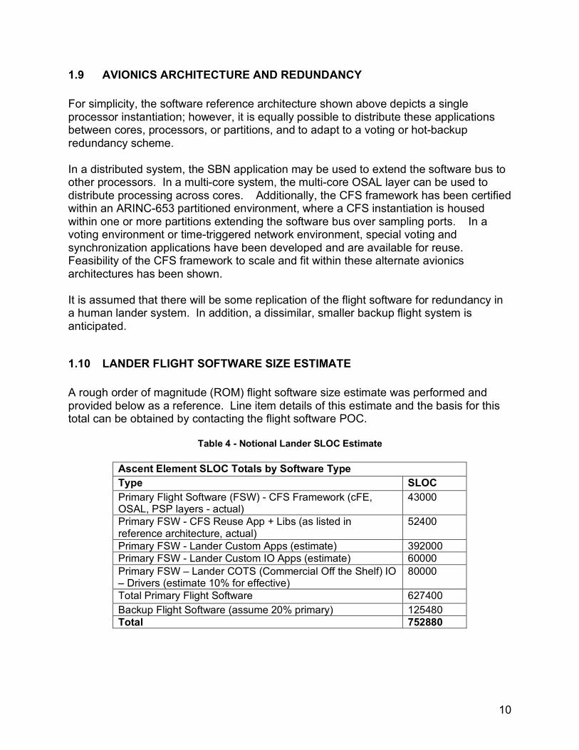
1.10 LANDER FLIGHT SOFTWARE SIZE ESTIMATE A rough order of magnitude (ROM) flight software size estimate was performed and provided below as a reference. Line item details of this estimate and the basis for this total can be obtained by contacting the flight software POC.
Table 4 - Notional Lander SLOC Estimate
Ascent Element SLOC Totals by Software Type Type SLOC Primary Flight Software (FSW) - CFS Framework (cFE, OSAL, PSP layers - actual)
43000
Primary FSW - CFS Reuse App + Libs (as listed in reference architecture, actual)
52400
Primary FSW - Lander Custom Apps (estimate) 392000 Primary FSW - Lander Custom IO Apps (estimate) 60000 Primary FSW – Lander COTS (Commercial Off the Shelf) IO – Drivers (estimate 10% for effective)
80000
Total Primary Flight Software 627400 Backup Flight Software (assume 20% primary) 125480 Total 752880
11
2.0 AES MODULAR POWER SYSTEMS (AMPS) AMPS is an option for off-the-shelf circuit boards used for power switching and distribution, and could support the aggressive HLS schedule.
NASA POCs and TechPort link:
• [email protected], LCM Power Lead at JSC • [email protected], AMPS PM at GRC • https://techport.nasa.gov/view/10759
2.1 AMPS OVERVIEW AMPS is set of standardized electronics modules that can be arranged in various configurations to perform traditional functions for a spacecraft electrical power system. Prototypes of each of the power electronics modules have been developed by the NASA Glenn Research Center (GRC) to meet the Modular Electronics Standard for Space Power Systems (MESSPS). Additionally, each standardized electronics module prototype has been designed to meet the International Space Power Systems Interoperability Standard (ISPSIS) and the Gateway Electrical Power Quality Specification Requirements for 120VDC.
AMPS provides a modular power system and power controls for NASA’s future explorations missions. This modular power system would allow the program to minimize maintenance operations, improve power systems availability and reduce the number of unique spare parts. If all Gateway and HLS elements utilized AMPS, then sparing would be performed with fewer unique spares that would be common between all elements and that could be changed out easily by the crew if needed. There would be no large unique Orbit Replaceable Units (ORU) that would need to be stowed for each element for the lifetime of the program – sparing would be done at the smaller electronic card level. Due to the 10+ years lifetime of the program, it is anticipated that some electronic components will fail and will need to be replaced. Having a common set of cards that are universal to all elements would reduce cost, downtime, and stowage space allocations.
2.2 AMPS FUNCTIONS The different standardized AMPS electronics modules, when combined with a chassis, backplane, and connectors, can be configured to perform for the following functions:
• Battery Charge / Discharge Unit (BCDU) • Primary Main Bus Switching Unit (MBSU) • Secondary Bus Switching Unit (SBSU) • DC to DC Converter Unit (DDCU) • Power Distribution Unit (PDU)
These functions can utilize the AMPS electronics modules installed into a standard 3U size rack setup, which is referred to as a Modular Electronic Unit (MEU). To configure
12
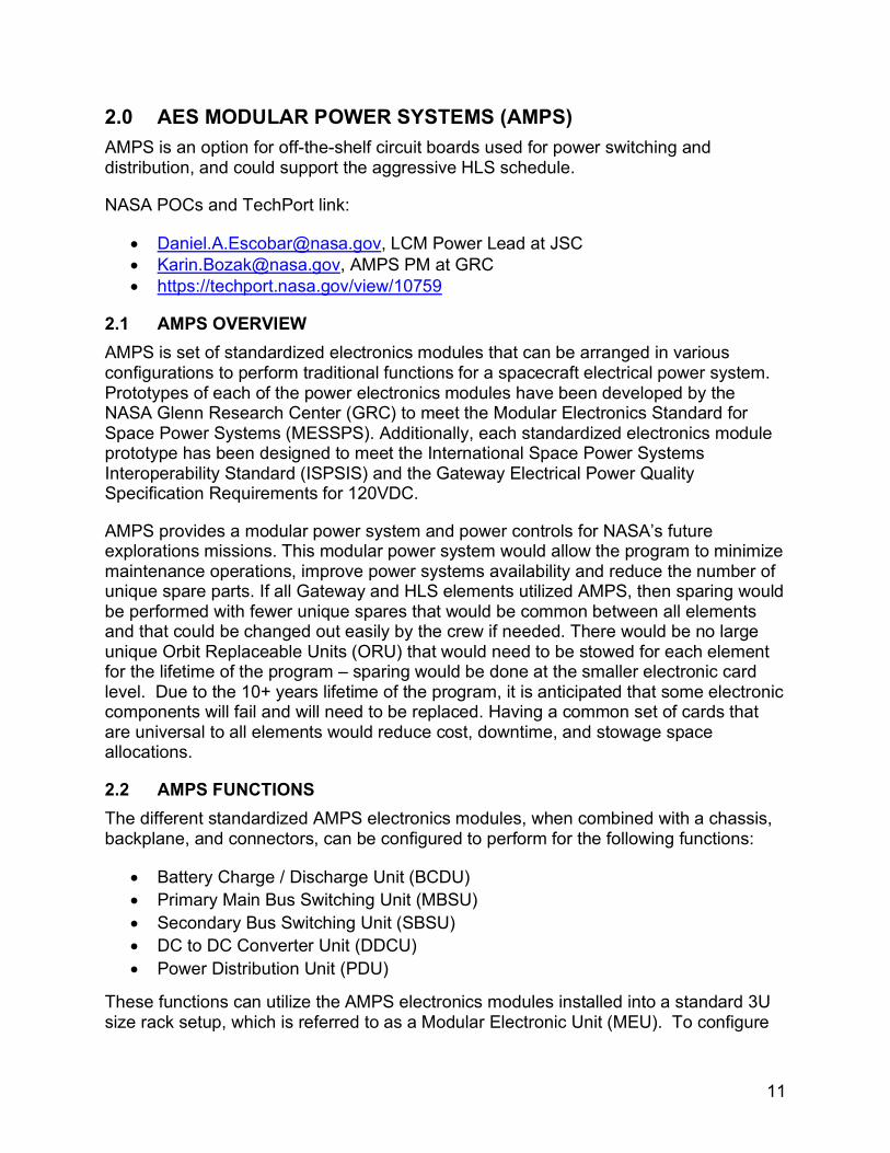
the different electronics module and to increase the output current capability, the spacecraft designer can develop a common backplane design to connect all the lower level AMPS electronic modules to perform the traditional functions required for an Electrical Power System (EPS). A simple graphical representation of how the cards can be combined into a rack is shown below.
Below is a list of each of the different AMPS electronics modules and a brief description of their functions.
• Controller Module (CTLM): o Provides the Spacecraft to internal network adapter, translates commands
and telemetry, and monitors the module status o Identifies and accommodates MEU type (DDCU, PDU etc.) and manage
configuration of MEU o Card size – 3U x 1 slot
• Housekeeping Power Module (HKPM): o Generates Housekeeping power bus (5VDC) from 120VDC source o Card size – 3U x 1 slot
• Load Switchgear Module (LSGM): o 4-channel unidirectional switch with configurable current limiting and
resettable trip o Provides four 4A independent switches that can be paralleled together to
increase the current switching capability (4A, 8A, 12A, 16A, etc.) o Each channel can switch up to 4A at 120VDC o Card size – 3U x 1 slot

13
• Bus Switchgear Module (BSGM): o Bidirectional bus switch (supply and return) with configurable resettable
trip levels o Can switch up to 40A at 120VDC o Card size – 3U x 1 slot
• Bidirectional Converter Module (BDCM): o Bidirectional DC/DC converter with configurable current and voltage
setpoints o Configurable and resettable trip levels o Primary: 10A at 120VDC o Secondary: Either 10A at 120VDC or 40A at 28VDC o Card size – 3U x 3 slots
• Portable Equipment Power Module (PEPM) o Variable output, isolating DC/DC Converter (3VDC – 28VDC @ 5.3A) o Load cable or user programmable output with remote voltage sense o Card size – 3U x 1 slot
• High Current Switchgear Module (HCSM) o Bidirectional supply side switch with configurable and resettable trip levels o Can switch up to 200A at 120VDC o Card size – 3U x 3 slots
2.3 AMPS TECHNOLOGY READINESS LEVEL (TRL) NASA GRC has prototype AMPS electronics modules estimated at TRL-4, and they anticipate performing integrated testing this fall to achieve TRL-5 by the end of 2019. A Request for Information (RFI) has been released, resulting in feedback from multiple electronics providers stating they could produce flight ready, TRL-9 AMPS hardware to meet the MESSPS in 24 months from the contract award date. This time-frame is highly dependent on the availability of critical electronic components, so the 24 month schedule could be accelerated if electronic components are available.
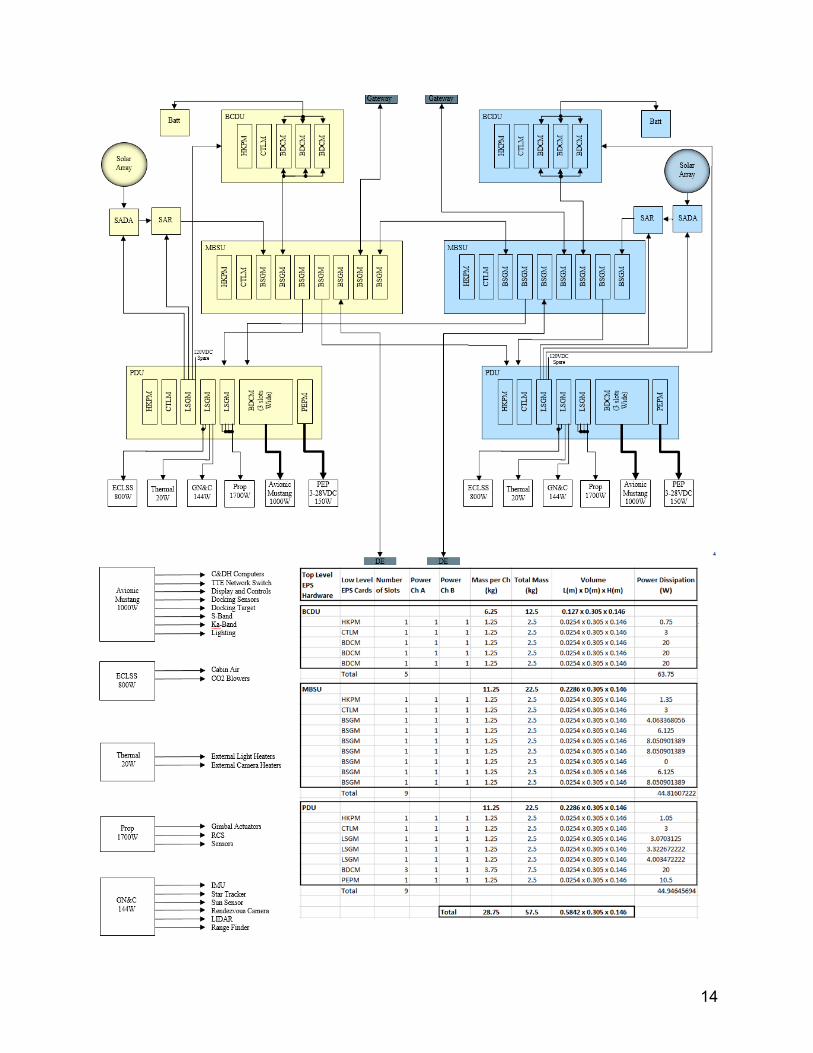
2.4 AMPS IN AN ELECTRICAL POWER SYSTEM (EPS) ARCHITECTURE An example for a possible Lander Ascent Element EPS architecture is shown below to demonstrate how the various AMPS electronics modules can be combined. For this architecture, each of the subsystems (ECLSS, Thermal, GN&C, Propulsion, Avionics) will receive a single 120VDC powered input (except for Avionics which will receive a 28VDC input to show the different capabilities of the AMPS electronics modules), and then those subsystems will perform the control and switching to their lower level components. AMPS electronics modules could also perform these switching functions just by increasing the number of PDU cards.
14
15
The above architecture is notional and is missing interfaces such as Camera systems and EVA Suits that will require power, but it is a starting point that shows the flexibility of the AMPS electronics modules. An advantage of this architecture is that by simply adding additional LSGMs to the PDU, that adds the capability to supply 120VDC power for any additional loads. In the Lander Ascent Element EPS architecture shown here, the size and mass estimates are based on the AMPS prototype modules and modular electronics units. The volume and dimension estimates used for each type of electronics module are based on the standardized 3U module size. The mass estimate is a rough estimate that is inclusive of not only the electronics module, but also the supporting chassis, backplane, internal cabling and connectors.
Each additional LSGM (each LSGM electronics module contains four 4A switches) would require increasing the length of the PDU by just 0.0254m per electronics module and the mass by 1.25kg per additional electronics module (again, the 1.25kg mass estimate is inclusive of the supporting chassis, backplane, internal cabling, and connectors).
• Each BCDU: ~0.127m x 0.305m x 0.146m, mass = 6.25 kg • Each MBSU ~0.2286m x 0.305m x 0.146m, mass = 11.25 kg • Each PDU: ~0.2286m x 0.305m x 0.146m, mass = 11.25 kg
For a single fault tolerant architecture with two units for each BCDU, MBSU and PDU, there will be a total mass of 57.5 kg. This does not include the mass of batteries, solar arrays, or the complete wiring harnesses for the vehicle.
16
3.0 DOCKING SYSTEMS NASA POCs:
• [email protected], Docking/Mating Lead at JSC • [email protected], Docking System Domain Lead at JSC
Docking system experts at JSC performed trade studies addressing a full range of options for establishing an expected HLS docking interface mass estimate, as well as options to reduce mass for HLS while considering impacts to the Exploration Architecture, performance, operations, and reliability. The trades explored options which deviate from adherence to the current baseline International Docking System Standard (IDSS), the consequences of which have far reaching impacts to Orion and the Gateway vehicles. Currently, the Orion will be configured with an active NASA Docking System Block 2 (NDSB2) and the Gateway with passive NDSB2.
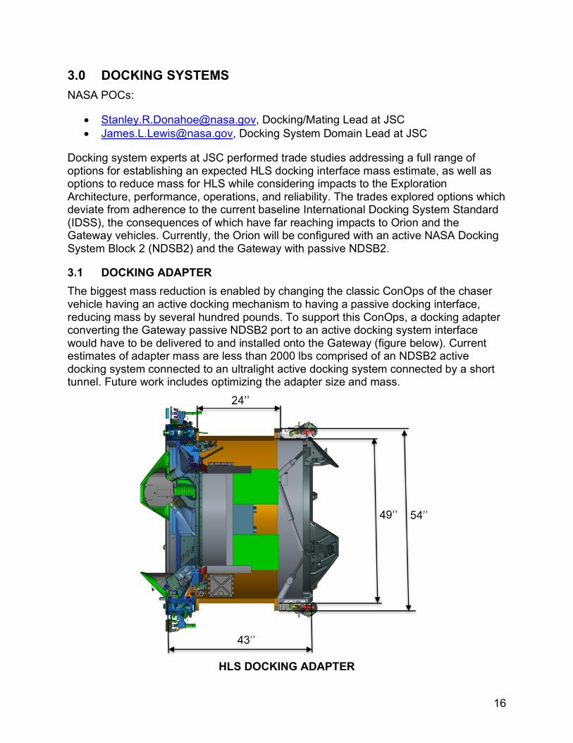
3.1 DOCKING ADAPTER The biggest mass reduction is enabled by changing the classic ConOps of the chaser vehicle having an active docking mechanism to having a passive docking interface, reducing mass by several hundred pounds. To support this ConOps, a docking adapter converting the Gateway passive NDSB2 port to an active docking system interface would have to be delivered to and installed onto the Gateway (figure below). Current estimates of adapter mass are less than 2000 lbs comprised of an NDSB2 active docking system connected to an ultralight active docking system connected by a short tunnel. Future work includes optimizing the adapter size and mass.
HLS DOCKING ADAPTER

17
3.2 DOCKING SYSTEM OPTIONS Three options were down-selected studied for a normalized mass comparison. The masses shown in the table below consist of only the fundamental components and features required for docking operations and are used for a fair comparison between the options. The total masses for the final system will be larger depending on additional features to be added.
A. Full IDSS (NDS or other known systems developed or in development) B. Partial IDSS (soft capture compatible) C. Non-IDSS
HLS Docking Options
A detailed mass assessment considered the structural and mechanical components that are relevant to trading these 3 options, as shown above. For the mass trade, each system utilizes a 7-inch docking tunnel height.
• Option A (IDSS) uses a tangential latch configuration for hard mate and requires passive hooks with a stack of spring washers on the passive HLS side for interface compliance. The soft capture system consists of alignment guide petals and body latches for the soft capture latches to engage.
• Option B uses a radial latch configuration for hard mate. With this approach, passive latches are not required on the HLS side eliminating the need for the 12 passive hooks present on the tangential configuration of Option A. The radial latch engages with a structural lip feature on the docking tunnel similar to the Apollo docking
18
mechanism design. The passive soft capture interface on the HLS side is totally conformant to the IDSS by having standard guide petals and body latches.
• Option C is a non-IDSS system utilizing the same radial latch hard mate system as Option B but incorporates a non-IDSS soft capture interface. This concept uses simpler, more compact features to achieve capture and alignment.
Each option is illustrated above with a docking tunnel which would be bolted directly to the HLS. In the interest of mass savings, a direct integration of docking components to the HLS structure is recommended. There are variants based on each option, and the mass estimates in this assessment can be further optimized.
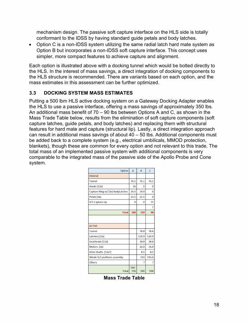
3.3 DOCKING SYSTEM MASS ESTIMATES Putting a 500 lbm HLS active docking system on a Gateway Docking Adapter enables the HLS to use a passive interface, offering a mass savings of approximately 350 lbs. An additional mass benefit of 70 – 90 lbs between Options A and C, as shown in the Mass Trade Table below, results from the elimination of soft capture components (soft capture latches, guide petals, and body latches) and replacing them with structural features for hard mate and capture (structural lip). Lastly, a direct integration approach can result in additional mass savings of about 40 – 50 lbs. Additional components must be added back to a complete system (e.g., electrical umbilicals, MMOD protection, blankets), though these are common for every option and not relevant to this trade. The total mass of an implemented passive system with additional components is very comparable to the integrated mass of the passive side of the Apollo Probe and Cone system.
Mass Trade Table
19
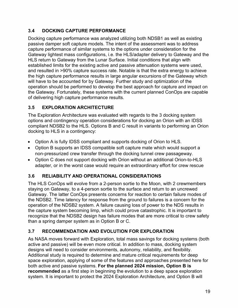
3.4 DOCKING CAPTURE PERFORMANCE Docking capture performance was analyzed utilizing both NDSB1 as well as existing passive damper soft capture models. The intent of the assessment was to address capture performance of similar systems to the options under consideration for the Gateway lightest mass configurations, i.e. the HLS/adapter delivery to Gateway and the HLS return to Gateway from the Lunar Surface. Initial conditions that align with established limits for the existing active and passive attenuation systems were used, and resulted in >90% capture success rate. Notable is that the extra energy to achieve the high capture performance results in large angular excursions of the Gateway which will have to be accounted for by Gateway. Further study and optimization of the operation should be performed to develop the best approach for capture and impact on the Gateway. Fortunately, these systems with the current planned ConOps are capable of delivering high capture performance results.
3.5 EXPLORATION ARCHITECTURE The Exploration Architecture was evaluated with regards to the 3 docking system options and contingency operation considerations for docking an Orion with an IDSS compliant NDSB2 to the HLS. Options B and C result in variants to performing an Orion docking to HLS in a contingency:
• Option A is fully IDSS compliant and supports docking of Orion to HLS. • Option B supports an IDSS compatible soft capture mate which would support a
non-pressurized crew transfer through the docking tunnel crew passageway. • Option C does not support docking with Orion without an additional Orion-to-HLS
adapter, or in the worst case would require an extraordinary effort for crew rescue
3.6 RELIABILITY AND OPERATIONAL CONSIDERATIONS The HLS ConOps will evolve from a 2-person sortie to the Moon, with 2 crewmembers staying on Gateway, to a 4-person sortie to the surface and return to an uncrewed Gateway. The latter ConOps presents concerns for reaction to certain failure modes of the NDSB2. Time latency for response from the ground to failures is a concern for the operation of the NDSB2 system. A failure causing loss of power to the NDS results in the capture system becoming limp, which could prove catastrophic. It is important to recognize that the NDSB2 design has failure modes that are more critical to crew safety than a spring damper system as in Option B or C.
3.7 RECOMMENDATION AND EVOLUTION FOR EXPLORATION As NASA moves forward with Exploration, total mass savings for docking systems (both active and passive) will be even more critical. In addition to mass, docking system designs will need to consider environments, autonomy, reliability, and flexibility. Additional study is required to determine and mature critical requirements for deep space exploration, applying of some of the features and approaches presented here for both active and passive systems. For the planned 2024 mission, Option B is recommended as a first step in beginning the evolution to a deep space exploration system. It is important to protect the 2024 Exploration Architecture, and Option B will
20
protect Orion to HLS docking contingency operations for crew rescue. An Option B active system would employ an IDSS compatible passive damper soft capture system whose components are technically mature and has been demonstrated through ground and flight demonstration.
Additional mass savings are achievable by direct integration of a passive interface into the HLS vehicle. The integrated interface is expected to weigh just over 100 lbs, achieved from the delta mass savings on the passive side for Option B which utilizes a radial latch configuration interface not requiring IDSS hard mate hooks, i.e. only a structural lip is needed. Furthermore, radial latches eliminate thermal delta temperature constraints which IDSS tangential latch interfaces are sensitive to. A radial latch design is available from the Constellation Program and can be matured to the requirements of HLS. Finally, additional mass savings are achievable from Option B active systems and should be studied further to improve on existing systems with masses ranging from 500-750 lbs (NDS). Further study should include the capabilities needed for docking capture systems for deep space utilization as mass savings are pursued. It is possible that smarter docking systems offer greater flexibility to cover a wide range of vehicle mass classes and CGs and operational constraints are more favorable. On the other hand, simpler, less capable systems offer improved reliability while putting more constraints on host vehicle capabilities.
An Option B implementation can be a first step which addresses contingencies, mass optimization, system reliability and operations, and offers a step towards the next generation docking system for exploration. This system installed on the HLS adapter will be the first interface for HLS. While determining the next steps for soft capture capability, NASA will have the opportunity to retrofit the interface during the Gateway and HLS Programs life cycle. It is anticipated that the installed active docking system will need to be replaced due to failure, environmental degradation, or life cycle limitations. This is an opportunity to learn and design for the impacts of deep space environments. NASA’s ISS experience indicates that multiple mechanical mating/docking systems are required to address specific requirements of each element’s mission or phase. Similarly, an adjustment to an IDSS-only approach should be considered to address the specific needs of the HLS missions. It is anticipated that any docking derivative developed for HLS can be used, if desired, by other vehicles visiting the Gateway, creating a deep space standard that is lighter and more reliable than IDSS. Once available, such as system can offer mass savings and operational constraint relief for Orion and logistics missions with the appropriate adaptation.
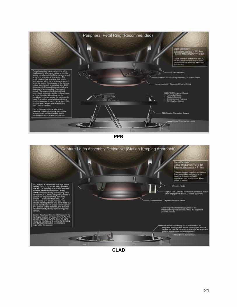
3.8 INTER-ELEMENT MATING The NASA HLS reference design requires autonomous mating of a Descent Element (DE) with an Ascent Element (AE) at or near the Gateway. Two concepts for this function have been studied:
1. Peripheral Petal Ring (PPR) Concept (recommended) 2. Capture Latch Assembly Derivative (CLAD) Concept
21
PPR
CLAD
22
Both of these systems were sized to accommodate integration outside the operational envelop of the ascent engine bell. The PPR system offers the most flexibility in that it can be docked with modified IDSS ICCs or loiter and dock. The CLAD option requires a much more stringent GNC “fly like an arm” capability. The peripheral system is a passive damper design and utilizes existing components of IDSS docking systems. Utilizing components common with HLS docking system discussed earlier in this paper should be considered. Direct integration of AE to DE passive components into the structural design of the HLS is recommended. Structural integration of the active system to the DE is assumed to be at the standard 1575 mm diameter payload attachment fitting. Additional assessments are required to evaluate petal orientation (inward vs outward), active ring petals vs no ring petals, soft capture latch mounting location, hard capture hooks (tangential vs radial), capture performance for optimization of operational technique, and integration into HLS element vehicles. Finally, it is assumed that the system described here will be utilized for the mating between the DE and Transfer Element (TE) with similar integration interfaces and sharing of common design components.
23
4.0 OPTICAL NAVIGATION (OPNAV) NASA POC:
• [email protected], PhD, LCM FSW Lead at JSC
4.1 OPNAV OVERVIEW Optical Navigation (OpNav) software has been developed, verified, and certified Class A (March 2018) by NASA JSC as Government Furnished Equipment (GFE). It is a navigation sensor that produces range and bearing to either the Earth or the Moon as a target, along with orientation/attitude, with a degree of accuracy to achieve successful entry burn targeting. It is first being flown on the Orion Exploration Mission 1 (EM-1).
The OpNav software analyzes optical still images using a commercial camera to provide navigation data (range, bearing, and attitude) to the primary GNC flight software, and will be used on the Orion EM-1 mission as the primary sensor to successfully return the vehicle to Earth in the event of permanent communications loss. The technology was developed over several years, and represents the ability to autonomously produce navigation course updates in the Earth-Moon system onboard a spacecraft rather than relying on the ground, which is highly applicable to advanced exploration and Lunar or Gateway mission scenarios.
By taking still optical images and analyzing the curvature of bodies, the software determines range and bearing to target with sub-pixel accuracy. The sensor provides attitude updates based on star imagery. To maintain high accuracy, the system self-calibrates in real-time onboard to compensate for lens distortion, or to correct attitude for camera boresight mounting fluctuations.
The software runs within the Core Flight Software (CFS) framework and was developed according to CMMI Level 3 and 7150.2B processes for safety-critical software. The software was verified with a rigorous test campaign consisting of unit, functional, and real-time tests using over 4000 images. The software is currently in formal integration testing for the Orion EM-1 mission and will be validated on the outbound leg.
Future revisions of this navigation instrument and software are planned to extend range and bearing measurements to rendezvous targets such as the Gateway, and to perform star tracking.
24
5.0 SPACESUIT WATER MEMBRANE EVAPORATOR (SWME) NASA POCs:
• [email protected], LCM ATCS Lead at JSC • [email protected], LCM ATCS at JSC
5.1 SWME OVERVIEW A consumable based Supplemental Heat Rejection Device (SHReD) is needed to enable HLS mission capabilities. Typical consumable based SHReDs include water sublimators and evaporators. Sublimators have been used in the past for the Saturn V rocket, LEM, and EMU. However, water sublimators are known to be susceptible to performance degradation due to contamination of the porous plates over time. Water membrane evaporators for use in next generation spacesuits have been under development for over 10 years and are known to be more tolerant of contaminated water sources than sublimators, making them more suitable for long duration usage at the vehicle level.
The primary implementation difference between the two SHReDs is that a membrane evaporator removes heat from the working fluid as it passes through a series of porous polypropylene hollow fibers, rather than requiring a secondary feedwater supply which provides water to a sublimator’s porous plates. Total heat rejection is controlled by a valve that regulates the backpressure around the fiber bundles, varying the cooling supplied by the unit. Current SWMEs are sized to provide a maximum heat rejection of roughly 800W to the primary thermal control loop. Completed spacesuit related testing includes a life test with over 1000 hours of operation which demonstrated minimal performance degradation over time. Additional testing includes vibration testing, integrated PLSS testing, burst pressure testing, etc.
HLS proposes to use a water membrane evaporator system as a SHReD in the thermal control system. While this is feasible given the high TRL of SWME, sizing and long duration testing of a 3.75 kW system must be completed before integration of the technology. Major objectives that must be completed before HLS integration include analysis and design of a water membrane evaporator size for at least 3.75 kW of heat rejection, full scale vacuum chamber testing for 15-30 days, and water quality characterization of the integrated system. Additionally, backpressure control in a vehicle application needs to be assessed, with hardware identified and tested for this function.
To reduce the consumable burden of the water membrane evaporator SHReD, a water-based radiator is also included in the reference HLS AE. A single-loop water coolant radiator has never been implemented in a human flight vehicle. The primary risk associated to utilizing such a system is coolant freezing in radiator tubing which results in a ruptured tube and renders the hardware useless. While heaters are included in the baseline to mitigate the risk of freezing the radiator, investigation of additional passive means to achieve this same function is desirable. Development must culminate in a full-scale thermal vacuum environment which mimics the thermal environment and variable heat loads the radiator will experience during the mission.