humanoid robot path planning with fuzzy markov...
TRANSCRIPT
A
ffmm©t
K
1
rlibst
wacmr
cime
s
M
1C
Available online at www.sciencedirect.com
Journal of Applied Researchand Technology
www.jart.ccadet.unam.mxJournal of Applied Research and Technology 14 (2016) 300–310
Original
Humanoid robot path planning with fuzzy Markov decision processesMahdi Fakoor ∗, Amirreza Kosari, Mohsen Jafarzadeh
Faculty of New Sciences & Technologies, University of Tehran, Tehran, Iran
Received 31 October 2015; accepted 4 June 2016Available online 21 August 2016
bstract
In contrast to the case of known environments, path planning in unknown environments, mostly for humanoid robots, is yet to be openedor further development. This is mainly attributed to the fact that obtaining thorough sensory information about an unknown environment is notunctionally or economically applicable. This study alleviates the latter problem by resorting to a novel approach through which the decision is
ade according to fuzzy Markov decision processes (FMDP), with regard to the pace. The experimental results show the efficiency of the proposedethod.2016 Universidad Nacional Autónoma de México, Centro de Ciencias Aplicadas y Desarrollo Tecnológico. This is an open access article underhe CC BY-NC-ND license (http://creativecommons.org/licenses/by-nc-nd/4.0/).
plan
Atwp
Hnu
spomnsf
•••
eywords: Fuzzy Markov decision processes; Vision based path planning; Path
. Introduction
The word “robot” originates from robota in Czech language,obota means work. So, we expect robots to work like expertabors. In the other words, we want robots to work in industrynstead of human labor forces. Since humans have appropriatelyuilt their environments with their ergonomic, robots that haveame physical body as human bodies are more useful than otherypes.
In order to design humanoid robots which are suitable fororking efficiently in industrial applications, several control
nd navigation problems such as stability, mapping, interacting,omputing, grasping and path planning must be investigated,ost especially path planning which is an open problem in this
esearch field.There is need for users and industries to have a robot that
an work in the real world. Since the real world is dynamic; its impossible to save all environments in robot memory. This
eans that we must prepare the robots to work in unknownnvironment.
∗ Corresponding author at: Faculty of New Sciences & Technologies, Univer-ity of Tehran, North Kargar Street, 1439955941 Tehran, Iran.
E-mail address: [email protected] (M. Fakoor).
Peer Review under the responsibility of Universidad Nacional Autónoma deéxico. t
http://dx.doi.org/10.1016/j.jart.2016.06.006665-6423/© 2016 Universidad Nacional Autónoma de México, Centro de CienciasC BY-NC-ND license (http://creativecommons.org/licenses/by-nc-nd/4.0/).
ning in unknown environments; Humanoid robots
Path planning has been studied in several research fields.lthough programming of a mobile robot to move from an ini-
ial position to a target position in a known environment is aell-known problem in robotics, but there are few methods inath planning in an unknown environment.
Medina-Santiago, Camas-Anzueto, Vazquez-Feijoo,ernández-de León, and Mota-Grajales (2014) implementedeural control systems in mobile robots in obstacle avoidancesing ultrasonic sensors with complex strategies.
Fuzzy logic is one of these methods that have been used inome related projects. A fuzzy-based navigator has been pro-osed by Zavlangas, Tzafestas, and Althoefer (2000) for thebstacle avoidance and navigation problem in omni-directionalobile robots. Their proposed navigator considered only the
earest obstacle in order to decide upon the robot’s next movingtep. This method utilized three parameters for path planning asollows:
the distance between the robot and the nearest obstacle, the angle between the robot and the nearest obstacle, and the angle between the robot direction and the straight line
connecting the current position to the target point.
Although this method was in real time and truly works, thesehree parameters are not needed for a camera humanoid robot.
Aplicadas y Desarrollo Tecnológico. This is an open access article under the
esearc
Ih
uwwtciTce
Apa
miiilartrahst
r1iaw(T(Bwiapan
perofa
bav
mtrrdsv
pamnmir
bsacm
afso
ewoeoa
(ppcwei
fettc
eips
M. Fakoor et al. / Journal of Applied R
n other words, this method can be utilized for any robot thatas omni-directional range sensors.
Fatmi, Yahmadi, Khriji, and Masmoudi (2006) proposed aseful way of implementing the navigation task in order to dealith the problem of wheeled mobile robot navigation. In theirork, issues of individual behavior design and action coordina-
ion of the behaviors were addressed utilizing fuzzy logic. Theoordination technique used in this work comprises two layers,.e., layer of primitive basic behaviors and the supervision layer.hey used 14 range sensors to achieve the position of any obsta-le surrounding the mobile robot. Thus, this method cannot bemployed with most humanoid robots.
Medina-Santiago, Anzueto, Pérez-Patricio, and Valdez-lemán (2013) presented a real-time programming for arototype robot to control its movement from one moment tonother one without showing response delays.
Iancu, Colhon, and Dupac (2010) presented a fuzzy reasoningethod of a Takagi–Sugeno type controller which was applied
n two wheels autonomous robot navigation. This mobile robots equipped with a sensorial system. The robot’s sensor areas divided into seven radial sectors labeled: large left, mediumeft and small left for the left areas, EZ for the straight area,nd large right, medium right and small right for the right area,espectively. Each radial sector was further divided into otherhree regions: small, medium and large. The sensor’s range couldecognize up to 30 m, and the robot could identify an obstaclenywhere inside the interval [−90◦, 90◦]. Undoubtedly, mostumanoid robots are not equipped with this large amount ofensors, hence, applying this method on humanoid robots seemso be impossible.
The simplest path planning algorithms for an unknown envi-onment are called Bug algorithms (Lumelsky & Stepanov,984). Bug algorithms solve the navigation problem by stor-ng only a minimal number of way points, without generating
full map of the environment. Traditional bug algorithms workith only tactile sensors. New bug algorithms, such as Distbug
Kamon & Rivlin, 1997), Visbug (Lumelsky & Skewis, 1990),angentbug (Kamon, Rimon, and Rivlin, 1998) and SensbugKim, Russell, and Koo, 2003), work with only range sensors.ug algorithms need to continuously update their position data,hile as we know, it is impossible to achieve a continuous update
n practice. Moreover, the bug model makes some simplifyingssumptions about the robot, i.e., the robot is a point object, it haserfect localization ability and it has perfect sensors. These threessumptions are unrealistic for robots, and so bug algorithms areot usually applied for practical navigation tasks directly.
Michel, Chestnutt, Kuffner, and Kanade (2005) proposed aath planning algorithm for humanoid robots. They used anxternal camera that showed the top view of the robot workingegion, hence, they could extract information about the positionf the robots and the obstacles. Their method is not applicableor most situations because it is impossible to use a camera with
global view of the robot work sites.
Furthermore, Nakhaei and Lamiraux (2008) utilized a com-ination of online 3D mapping and path planning. They utilized 3D occupancy grid that is updated incrementally by stereoision for constructing the model of the environment. A road
(cao
h and Technology 14 (2016) 300–310 301
ap-based method was employed for motion planning becausehe dimension of the configuration space was high for humanoidobots. Indeed, it was necessary to update the road map aftereceiving new visual information because the environment wasynamic. This algorithm was tested on HRP2. As a conclu-ion, their method was not efficient because it needs exact stereoision and a lot of time to find a path in each step.
In addition, Sabe et al. (2004) presented a method for pathlanning and obstacle avoidance for QRIO humanoid robot,llowing it to walk autonomously around the home environ-ent. They utilized an A* algorithm in their method; thus, it
eeds a lot of time to process. Furthermore, they utilized onlineapping and stereo vision. Their method seems effective, but
t needs stereo vision and high computational processes. As aesult, it cannot be applied in most conditions.
Other path planning project on HRP-2 humanoid robot haseen carried out by Michel et al. (2006). This method useseveral cameras in the robot environment in order to produce
suitable map. As mentioned before, we cannot utilize manyameras wherever we want to use humanoid robots and so thisethod cannot be applied either.Moreover, in another project, Chestnutt, Kuffner, Nishiwaki,
nd Kagami (2003) used the Best-first search and A* algorithmsor foot step path planning on a H7 humanoid robot. they demon-trated that A* is more effective than Best-first search. But bothf them need stereo vision and high computational processes.
In addition, Okada, Inaba, and Inoue (2003) followed a differ-nt route for humanoid robot path planning: robot and obstacleere considered cylindrical shapes, the floor was extracted basedn vision and then the robot made a decision. This method mayncounter a conflicting problem when the robot confronts a bigbstacle at its start point. In this situation, the robot could not beble to detect the floor which in turn leads to missing the path.
In addition, Gay, Dégallier, Pattacini, Ijspeert, and Victor2010) used artificial potential field algorithms in a recent pathlanning project on iCub (a humanoid robot). At first, in theirroposed algorithm, iCub calculated 3D position of each obsta-le and transformed it in 2D, and then the artificial potential fieldas calculated. Their method needs perfect knowledge of the
xtracted images to find the position of the obstacles; therefore,t may not be utilized in some humanoid robots applications.
As seen from the above study, an efficient and suitable methodor path planning for humanoid robots in dynamic unknownnvironments has not yet been proposed. Considering the iden-ified research gap in this paper, a new procedure, combininghe effects of fuzzy inference system and Markov decision pro-esses, is proposed.
The application of Markov decision processes results in fasterxecution of the procedure when compared to the ones proposedn studies such as those by Sabe et al. (2004). Moreover, in theroposed method, using a fuzzy inference system leads to amoother optimal path than the other previous past methods.
Moreover, resorting to fuzzy Markov decision processes
FMDP) obviates the necessity of having knowledge of the pre-ise shape, position and orientation of the surrounding obstacles,s well as the need for relatively enormous volumes of mem-ry for stocking information gathered in 2D and 3D maps. The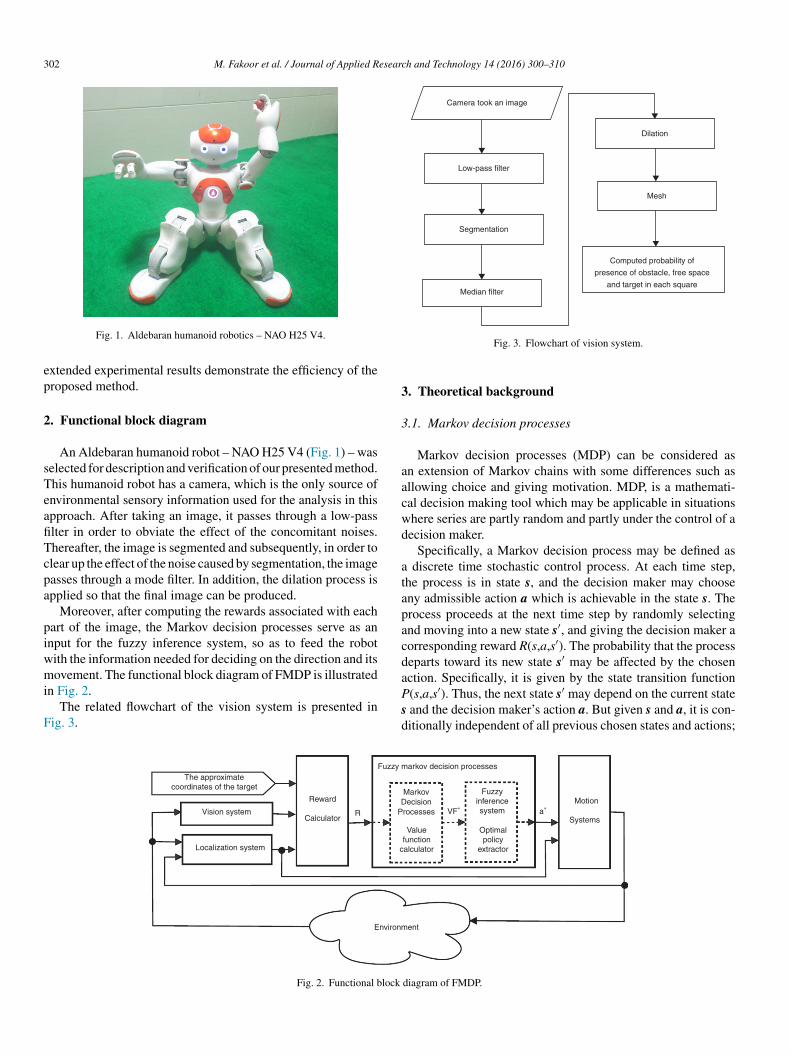
302 M. Fakoor et al. / Journal of Applied Research and Technology 14 (2016) 300–310
ep
2
sTeafiTcpa
piwmi
F
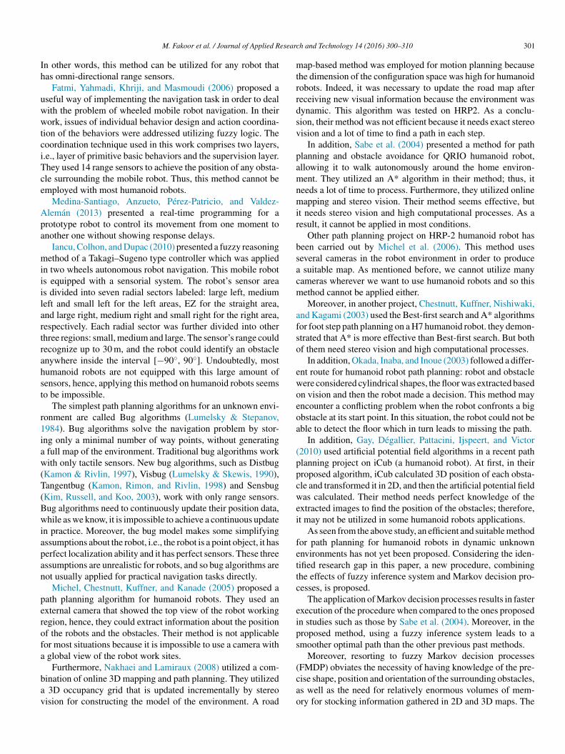
Camera took an image
Low-pass filter
Segmentation
Median filter
Computed probability of
presence of obstacle, free space
and target in each square
Mesh
Dilation
3
3
aacwd
atapacda
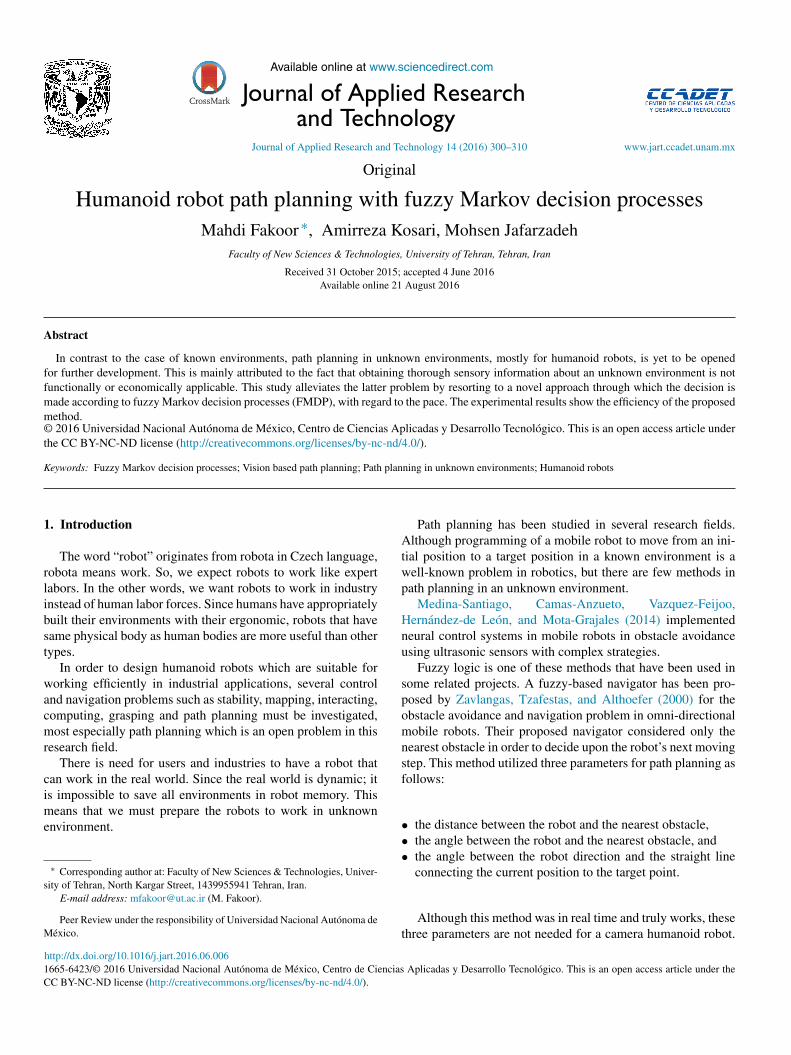
Fig. 1. Aldebaran humanoid robotics – NAO H25 V4.
xtended experimental results demonstrate the efficiency of theroposed method.
. Functional block diagram
An Aldebaran humanoid robot – NAO H25 V4 (Fig. 1) – waselected for description and verification of our presented method.his humanoid robot has a camera, which is the only source ofnvironmental sensory information used for the analysis in thispproach. After taking an image, it passes through a low-passlter in order to obviate the effect of the concomitant noises.hereafter, the image is segmented and subsequently, in order tolear up the effect of the noise caused by segmentation, the imageasses through a mode filter. In addition, the dilation process ispplied so that the final image can be produced.
Moreover, after computing the rewards associated with eachart of the image, the Markov decision processes serve as annput for the fuzzy inference system, so as to feed the robotith the information needed for deciding on the direction and itsovement. The functional block diagram of FMDP is illustrated
n Fig. 2.The related flowchart of the vision system is presented in
ig. 3.
Psd
The approximatecoordinates of the target
Vision system
Localization system
Calculator
DP
c
Environm
Reward
R
Fuzzy m
Fig. 2. Functional block
Fig. 3. Flowchart of vision system.
. Theoretical background
.1. Markov decision processes
Markov decision processes (MDP) can be considered asn extension of Markov chains with some differences such asllowing choice and giving motivation. MDP, is a mathemati-al decision making tool which may be applicable in situationshere series are partly random and partly under the control of aecision maker.
Specifically, a Markov decision process may be defined as discrete time stochastic control process. At each time step,he process is in state s, and the decision maker may chooseny admissible action a which is achievable in the state s. Therocess proceeds at the next time step by randomly selectingnd moving into a new state s′, and giving the decision maker aorresponding reward R(s,a,s′). The probability that the processeparts toward its new state s′ may be affected by the chosenction. Specifically, it is given by the state transition function
′ ′
(s,a,s ). Thus, the next state s may depend on the current state and the decision maker’s action a. But given s and a, it is con-itionally independent of all previous chosen states and actions;Markov Fuzzyinferencesystem
Motion
SystemsOptimalpolicy
extractor
VF∗ a∗ecision
rocesses
Valuefunctionalculator
ent
arkov decision processes
diagram of FMDP.
esearc
it
3
lsw
se
3
tSf
V
V
V
V
o
V
3
V
π
ffp
3
hatA
3
cflhpuitmssi
vc(diaomM
R
R
ssystems. Also, there is no standard method for defining themembership function to minimize error or maximize the outputaccuracy.
Output
Rule
Input
M. Fakoor et al. / Journal of Applied R
n other words, the state transitions of an MDP could possesshe Markov property (Puterman, 2014).
.1.1. PolicyFinding a “policy” for the decision maker is the main prob-
em in MDPs. “Policy” can be interpreted as a function π thatpecifies the action π(s) which the decision maker will choosehen is in state s.The goal is to select a policy π which could maximize
ome cumulative function of the random rewards, typically thexpected discounted sum over a potentially infinite horizon.
.1.2. Value functionValue function Vπ(s) is the expected value of total reward if
he system starts from state s and acts according to policy π.o each policy has its value function. It can be formulated asollows:
π(s) = E[R(s0) + γR(s1) + γ2R(s2) + · · · |π
](1)
π(s) = E
[N∑
t=0
γtR(st) |π]
(2)
Eq. (1) could be rewritten as follows:
π(s) = E[R(s0) + γ(R(s1) + γR(s2) + · · ·) |π ]
(3)
π(s) = E[R(s0) + γV (s1) |π ]
(4)
The Bellman equations can be gained by the simplificationf Eq. (4) as follows:
π(s) = R(s0) + γ∑s′
P(s, a, s′)Vπ(s′) (5)
.1.3. Optimal policy and optimal value functionIn the optimal case, we will have:
∗(s) = R(s) + maxa
γ∑s′
P(s, a, s′)V ∗(s′) (6)
∗(s) = arg maxa
γ∑s′
P(s, a, s′)V ∗(s′) (7)
If there are n states, then there are n Bellman equations, oneor each state. In addition, there are n unknown values. There-ore, by simultaneously solving these equations, the optimalolicy and optimal value function can be achieved.
.1.4. Value iteration algorithmAs we can see, the Bellman equations (6) are nonlinear,
ence they are difficult to solve. In this case, we utilize anlgorithm to extract the optimal policy or optimal value func-ion without directly solving the Bellman equations as shown inlgorithm 1.
h and Technology 14 (2016) 300–310 303
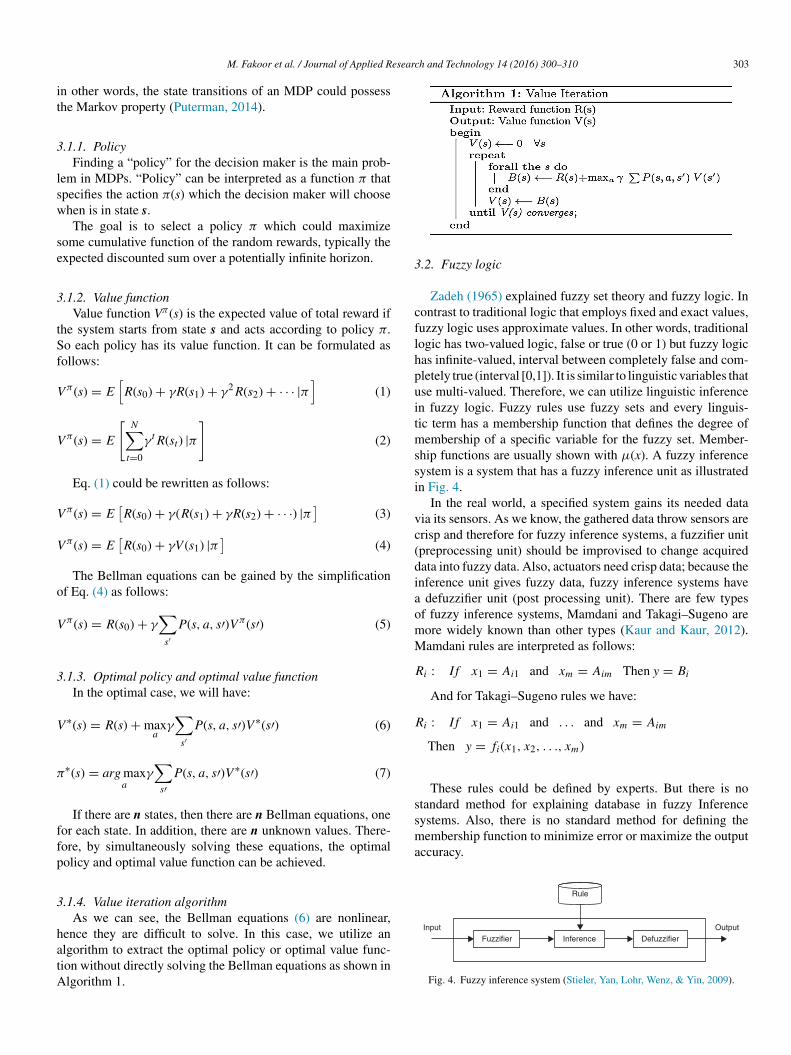
.2. Fuzzy logic
Zadeh (1965) explained fuzzy set theory and fuzzy logic. Inontrast to traditional logic that employs fixed and exact values,uzzy logic uses approximate values. In other words, traditionalogic has two-valued logic, false or true (0 or 1) but fuzzy logicas infinite-valued, interval between completely false and com-letely true (interval [0,1]). It is similar to linguistic variables thatse multi-valued. Therefore, we can utilize linguistic inferencen fuzzy logic. Fuzzy rules use fuzzy sets and every linguis-ic term has a membership function that defines the degree ofembership of a specific variable for the fuzzy set. Member-
hip functions are usually shown with μ(x). A fuzzy inferenceystem is a system that has a fuzzy inference unit as illustratedn Fig. 4.
In the real world, a specified system gains its needed dataia its sensors. As we know, the gathered data throw sensors arerisp and therefore for fuzzy inference systems, a fuzzifier unitpreprocessing unit) should be improvised to change acquiredata into fuzzy data. Also, actuators need crisp data; because thenference unit gives fuzzy data, fuzzy inference systems have
defuzzifier unit (post processing unit). There are few typesf fuzzy inference systems, Mamdani and Takagi–Sugeno areore widely known than other types (Kaur and Kaur, 2012).amdani rules are interpreted as follows:
i : If x1 = Ai1 and xm = Aim Then y = Bi
And for Takagi–Sugeno rules we have:
i : If x1 = Ai1 and . . . and xm = Aim
Then y = fi(x1, x2, . . ., xm)
These rules could be defined by experts. But there is notandard method for explaining database in fuzzy Inference
DefuzzifierInferenceFuzzifier
Fig. 4. Fuzzy inference system (Stieler, Yan, Lohr, Wenz, & Yin, 2009).
3 esearc
4
4
eraaAvufi
MaunesGtfTn
4
lusmi(wpt
aror
pi
4
mfi
4
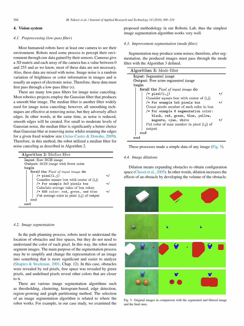
Dilation means expanding obstacles to obtain configurationspace (Choset et al., 2005). In other words, dilation increases theeffects of an obstacle by developing the volume of the obstacle.
04 M. Fakoor et al. / Journal of Applied R
. Vision system
.1. Preprocessing (low-pass filter)
Most humanoid robots have at least one camera to see theirnvironment. Robots need some process to percept their envi-onment through raw data gained by their sensors. Cameras give
3D matrix and each array of the camera has a value between 0nd 255 and as we know, most of these data are not necessary.lso, these data are mixed with noise. Image noise is a randomariation of brightness or color information in images and issually an aspect of electronic noise. Therefore, these data mustrst pass through a low-pass filter (s).
There are many low-pass filters for image noise canceling.ost robotics projects employ the Gaussian filter that produces
smooth blur image. The median filter is another filter widelysed for image noise canceling; however, all smoothing tech-iques are effective at removing noise, but they adversely affectdges. In other words, at the same time, as noise is reduced,mooth edges will be created. For small to moderate levels ofaussian noise, the median filter is significantly a better choice
han Gaussian blur at removing noise whilst retaining the edgesor a given fixed window size (Arias-Castro & Donoho, 2009).herefore, in this method, the robot utilized a median filter foroise canceling as described in Algorithm 2.
.2. Image segmentation
In the path planning process, robots need to understand theocation of obstacles and free spaces, but they do not need tonderstand the color of each pixel. In this way, the robot mustegment images. The main purpose of the segmentation processay be to simplify and change the representation of an image
nto something that is more significant and easier to analyzeShapiro & Stockman, 2001, Chap. 12). In this case, obstaclesere revealed by red pixels, free space was revealed by greenixels, and undefined pixels reveal other colors that are closero it.
There are various image segmentation algorithms such
s thresholding, clustering, histogram-based, edge detection,egion-growing and graph partitioning method. The selectionf an image segmentation algorithm is related to where theobot works. For example, in our case study, we examined theFa
h and Technology 14 (2016) 300–310
roposed methodology in our Robotic Lab, thus the simplestmage segmentation algorithm works very well.
.3. Improvement segmentation (mode filter)
Segmentation may produce some noises; therefore, after seg-entation, the produced images must pass through the modelter with the Algorithm 3 defined.
These processes made a simple data of any image (Fig. 5).
.4. Image dilations
ig. 5. Original images in comparison with the segmented and filtered imagend the final ones.

M. Fakoor et al. / Journal of Applied Researc
4
sWmaiNe
rpettfnbonbt
4
fooepFplt
P
P
P
5
Ietta
5
tFwtwi
5
hr
R
5
pc
R
6
urf
rawwsffuzzy mapping from state to action. Indeed, an optimal policy
Fig. 6. Example of effect of camera angle; top and perspective view.
.5. Mesh
In the situations in which the angle of the robot head is con-tant and the ground is flat, each pixel shows the same distance.e used this property to approximate the distances from ele-ents of obstacles. Since the robot has a specific physical size
nd predefined interval foot step, the exact position of each pixels not that important. Therefore, we should mesh the images.ow every square of the image shows information on the pres-
nce of the obstacle in relative position.Because the camera is located in the head of the humanoid
obot and it takes a specified angle with the ground, the imageicture by the robot is a perspective view. Fig. 6 illustrates theffect of the perspective view on a checkerboard. It reveals thathe meshes are not square. While it is expected that the result ofhe robot vision must be at some distance from the obstacles, butor computed distance from the robots’s image, the mesh must beon-homogeneous. In other words, the number of pixels in eachox at the bottom of the image must be greater than the numberf pixels in each box at the top of the image; in addition, theumber of pixels in each box at the middle of the image muste greater than the number of pixels in each box on the sides ofhe image.
.6. Probability calculation
The Markov decision process works on discrete states. There-ore, Markov decision processes need to understand the presencef the obstacle in each state. The best way to show the existencef obstacles in a state is by determining the probability of thexistence. In this way, the robot divides the number of obstacleixels in each square by the number of all pixels in the square.urthermore, Markov decision processes need to understand theresence of the obstacle in each state, which could be calcu-ated in a similar way. The following relations fully interprethis concept:
obstacle(i, j) = number of obstacle pixels in square (i, j)
number of all pixels in square (i, j)(8)
target(i, j) = number of target pixels in square (i, j)
number of all pixels in square (i, j)(9)
free space(i, j) = number of target pixels in square (i, j)
number of all pixels in square (i, j)(10) i
r
h and Technology 14 (2016) 300–310 305
. Reward calculation
Reward calculation is related to observation of the target.f the robot can see the target, it can use only the informationxtracted from the image; however, if the robot cannot see thearget (because of long distance), in addition to these informa-ion, it needs extra information on the coordination of the targetnd itself to create a sub-goal.
.1. Sub-goal
A sub-goal is defined as a virtual goal in vision space suchhat achieving it could guide the robot toward the original target.ig. 7 illustrates how the sub-goal state could be calculated. Ase can see, if the dark green circle is considered to be the target,
hen the state in light green is defined as the sub-goal; in a similaray, if the blue circle is considered to be the target, then the state
n cyan is known as the sub-goal state.
.2. Reward when the robot cannot see the obstacle
In this condition, the free space has −w1 point, the obstacleas −w2 point, and the sub-goal has +1 point; therefore, theeward function could be calculated as follows:
(i, j) = Psub-goal(i, j) + w1Pfree space(i, j)
+ w2Pobstacale(i, j) (11)
.3. Reward when the robot can see the obstacle
In this condition, the target has +1, the free space has −w1oint, and the obstacle has −w2 point; thus, the reward functionould be calculated as follows:
(i, j) = Ptarget(i, j) + w1Pfree space(i, j) + w2Pobstacale(i, j)
(12)
. Designed Fuzzy Markov Decision Process
A Fuzzy Markov Decision Process (FMDP) represents thencertain knowledge about the environment in the form of offer-esponse patterns such as triangular and Gaussian membershipunctions.
In the Fuzzy Markov Decision Process (FMDP) designed, theobot begins from its start state, it must choose a suitable actiont each time step. In this problem, it is supposed that the actionshich lead the robot to go out of its state do not work, in otherords, we could say that the adjacent has a similar reward. The
olution that is called policy (π(s)) is infrequence from the valueunction. The designed policy is illustrated in Fig. 8, which is a
s a policy that maximizes the expected value of accumulatedewards throughout time.

306 M. Fakoor et al. / Journal of Applied Research and Technology 14 (2016) 300–310
Fig. 7. Example of determining sub-goal state. Dark green: target 1; blue: target2; red: target 3; light green: sub-goal 1; cyan: sub-goal 2; pink: sub-goal 3. (Forit
6
aidta∑
pbs
0.2 0.4 0.2
0.1 0.1
Fd
tan3
fwi
6
tt
nterpretation of reference to color in this figure legend, the reader is referred tohe web version of this article.)
.1. Value function
Unfortunately, in the real world, humanoid robot’s actionsre unreliable for some recognized reasons such as noise ofnput data, ineffectiveness control systems, un-modeled systemynamic and environment changes throughout time; therefore,he probability of going from state s to state s′ by choosing action
with P(s, a, s′) will be:
s′P(s, a, s′) = 1, 0 ≤ P(s, a, s′) ≤ 1 (13)
As a result, the robot must decide to act for increasing the
robability of success throughout time. An example of proba-ility in the robot action when the robot wants to go to the nexttate decided is illustrated in Fig. 9.cvt
Imageprocessi
Takenimage
State
Environment
ActionFuzzy
inference
Fuzzyaction
Fuzz
Fig. 8. Data
ig. 9. Example of probability in action when robot wants to go to next stateecide.
At first, it is supposed that the optimal policy is equal tohe traditional optimal policy; hence, the value function will bechieved by solving Eqs. (6) and (7). As mentioned before, thisonlinear equation can be solved with a value iteration (Section.1.4).
In the next step, forgetting the gained optimal policy, the valueunction will be determined based on decision making. In otherords, we utilize the value function as an input for the fuzzy
nference system.
.2. Fuzzification
As we know, the extremum of the value function is relatedo the reward function, while the reward function is related tohe environment and user definition, therefore the value function
an take any interval. But as we know, the fuzzy input must be aector where the array is a real number between 0 and 1. Thus,he fuzzification is important for continuation.ng Imageunderstamding
Valueiteration
Fuzzifiedvalue
function
Fuzzification
Valuefunction
RewardsProcessed
image
Vision system
y markov decision processes
flow.
M. Fakoor et al. / Journal of Applied Research and Technology 14 (2016) 300–310 307
r ≤√2
r ≤ √5 r ≤ √10
r ≤2
wttf
Gnaivf
μ
wfo
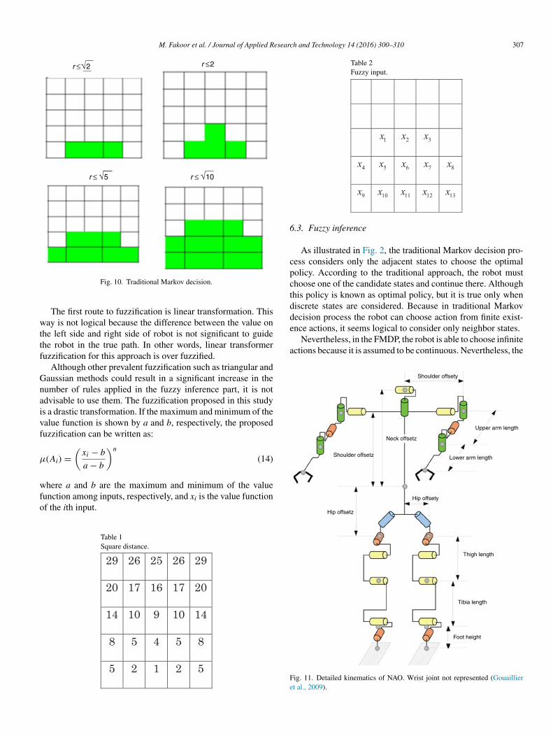
Table 2Fuzzy input.
6
cpctddence actions, it seems logical to consider only neighbor states.
Nevertheless, in the FMDP, the robot is able to choose infiniteactions because it is assumed to be continuous. Nevertheless, the
Shoulder offsety
Neck offsetz
Shoulder offsetz
Upper arm length
Lower arm length
Fig. 10. Traditional Markov decision.
The first route to fuzzification is linear transformation. Thisay is not logical because the difference between the value on
he left side and right side of robot is not significant to guidehe robot in the true path. In other words, linear transformeruzzification for this approach is over fuzzified.
Although other prevalent fuzzification such as triangular andaussian methods could result in a significant increase in theumber of rules applied in the fuzzy inference part, it is notdvisable to use them. The fuzzification proposed in this studys a drastic transformation. If the maximum and minimum of thealue function is shown by a and b, respectively, the proposeduzzification can be written as:
(Ai) =(
xi − b
a − b
)n
(14)
here a and b are the maximum and minimum of the value
unction among inputs, respectively, and xi is the value functionf the ith input.Table 1Square distance.
Fe
.3. Fuzzy inference
As illustrated in Fig. 2, the traditional Markov decision pro-ess considers only the adjacent states to choose the optimalolicy. According to the traditional approach, the robot musthoose one of the candidate states and continue there. Althoughhis policy is known as optimal policy, but it is true only wheniscrete states are considered. Because in traditional Markovecision process the robot can choose action from finite exist-
Hip offsety
Hip offsetz
Thigh length
Tibia length
Foot height
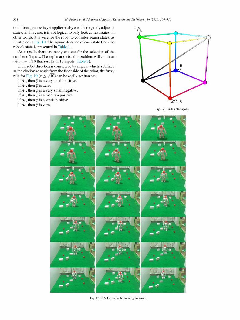
ig. 11. Detailed kinematics of NAO. Wrist joint not represented (Gouailliert al., 2009).
3 esearch and Technology 14 (2016) 300–310
tsoir
nw
ar
G
B
08 M. Fakoor et al. / Journal of Applied R
raditional process is yet applicable by considering only adjacenttates; in this case, it is not logical to only look at next states; inther words, it is wise for the robot to consider nearer states, asllustrated in Fig. 10. The square distance of each state from theobot’s state is presented in Table 1.
As a result, there are many choices for the selection of theumber of inputs. The explanation for this problem will continueith r = √
10 that results in 13 inputs (Table 2).If the robot direction is considered by angle ϕ which is defined
s the clockwise angle from the front side of the robot, the fuzzyule for Fig. 10 (r ≤ √
10) can be easily written as:If A1, then ϕ̂ is a very small positive.If A2, then ϕ̂ is zero.If A3, then ϕ̂ is a very small negative.
If A4, then ϕ̂ is a medium positiveIf A5, then ϕ̂ is a small positiveIf A6, then ϕ̂ is zeroR
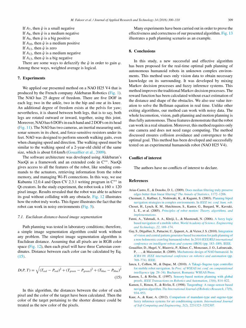
Fig. 12. RGB color space.
Fig. 13. NAO robot path planning scenario.
esearc
A
7
pTeAnlM(sfwss
NgmmKQpihr
7
aaEsd(
D
pct
ei
8
hamkMmrtaewtcodot
C
R
A
C
C
F
G
G
I
K
K
M. Fakoor et al. / Journal of Applied R
If A7, then ϕ̂ is a small negativeIf A8, then ϕ̂ is a medium negativeIf A9, then ϕ̂ is a big positiveIf A10, then ϕ̂ is a medium positiveIf A11, then ϕ̂ is zeroIf A12, then ϕ̂ is a medium negativeIf A13, then ϕ̂ is a big negativeThere are some ways to defuzzify the ϕ̂ in order to gain ϕ.
mong these ways, weighted average is logical.
. Experiments
We applied our presented method on a NAO H25 V4 that isroduced by the French company Aldebaran Robotics (Fig. 1).he NAO has 25 degree of freedom. There are five DOF inach leg; two in the ankle, two in the hip and one at its knee.n additional degree of freedom exists at the pelvis for yaw;evertheless, it is shared between both legs, that is to say, bothegs are rotated outward or inward, together, using this joint.
oreover, NAO has 6 DOFs in each hand and 2 DOFs on its headFig. 11). The NAO has two cameras, an inertial measuring unit,onar sensors in its chest, and force-sensitive resistors under itseet. NAO was designed to perform smooth walking gaits, evenhen changing speed and direction. The walking speed must be
imilar to the walking speed of a 2-year-old child of the sameize, which is about 0.6 km/h (Gouaillier et al., 2009).
The software architecture was developed using Aldebaran’saoQi as a framework and an extended code in C++. NaoQiives access to all the features of the robot, like sending com-ands to the actuators, retrieving information from the robotemory, and managing Wi-Fi connections. In this way, we useubuntu 12.0.4 and Open CV 2.3.1 writing program in C++ int creators. In the study experiment, the robot took a 160 × 120ixel image. Results revealed that the robot was able to achievets goal without colliding with any obstacle. Fig. 12 illustratesow the robot truly works. This figure illustrates the fact that theobot can work in noisy environments (Fig. 5).
.1. Euclidean distance-based image segmentation
Path planning was tested in laboratory conditions; therefore, simple image segmentation algorithm could work withoutny problem. The simplest image segmentation algorithm isuclidean distance. Assuming that all pixels are in RGB colorpace (Fig. 12), then each pixel will have three Cartesian coor-inates. Distance between each color can be calculated by Eq.15).
(P, T ) =√
(Tred − Pred)2 + (Tgreen − Pgreen)2 + (Tblue − Pblue)2
(15)
In this algorithm, the distances between the color of eachixel and the color of the target have been calculated. Then theolor of the target pertaining to the shorter distance could bereated as the new color of the pixels.
K
h and Technology 14 (2016) 300–310 309
Many experiments have been carried out in order to prove theffectiveness and correctness of our presented algorithm. Fig. 13llustrates a path planning scenario as an example.
. Conclusions
In this study, a new successful and effective algorithmas been proposed for the real-time optimal path planning ofutonomous humanoid robots in unknown complex environ-ents. This method uses only vision data to obtain necessary
nowledge on its surrounding. It was developed by mixingarkov decision processes and fuzzy inference systems. Thisethod improves the traditional Markov decision processes. The
eward function has been calculated without exact estimation ofhe distance and shape of the obstacles. We also use value iter-tion to solve the Bellman equation in real time. Unlike otherxiting algorithms, our method can work with noisy data. Thehole locomotion, vision, path planning and motion planning is
hus fully autonomous. These features demonstrate that the robotan work in a real situation. Moreover, this method requires onlyne camera and does not need range computing. The methodiscussed ensures collision avoidance and convergence to theptimal goal. This method has been developed and successfullyested on an experimental humanoids robot (NAO H25 V4).
onflict of interest
The authors have no conflicts of interest to declare.
eferences
rias-Castro, E., & Donoho, D. L. (2009). Does median filtering truly preserveedges better than linear filtering? The Annals of Statistics, 1172–1206.
hestnutt, J., Kuffner, J., Nishiwaki, K., & Kagami, S. (2003). Planning bipednavigation strategies in complex environments. In IEEE int. conf. hum. rob.
hoset, H., Lynch, K. M., Hutchinson, S., Kantor, G., Burgard, W., Kavraki,L. E., et al. (2005). Principles of robot motion: Theory, algorithms, andimplementations.
atmi, A., Yahmadi, A. A., Khriji, L., & Masmoudi, N. (2006). A fuzzy logicbased navigation of a mobile robot. World Academy of Science. Engineeringand Technology, 22, 169–174.
ay, S., Dégallier, S., Pattacini, U., Ijspeert, A., & Victor, J. S. (2010). Integrationof vision and central pattern generator based locomotion for path planning ofa non-holonomic crawling humanoid robot. In 2010 IEEE/RSJ internationalconference on intelligent robots and systems (IROS) (pp. 183–189). IEEE.
ouaillier, D., Hugel, V., Blazevic, P., Kilner, C., Monceaux, J. O., Lafourcade,P., . . ., & Maisonnier, B. (2009). Mechatronic design of NAO humanoid. InICRA’09. IEEE international conference on robotics and automation (pp.769–774). IEEE.
ancu, I., Colhon, M., & Dupac, M. (2010). A Takagi–Sugeno type controllerfor mobile robot navigation. In Proc. of WSEAS int. conf. on computationalintelligence (pp. 29–34). Bucharest, Romania: WSEAS Press.
amon, I., & Rivlin, E. (1997). Sensory-based motion planning with globalproofs. IEEE Transactions on Robotics and Automation, 13(6), 814–822.
amon, I., Rimon, E., & Rivlin, E. (1998). Tangentbug: A range-sensor-basednavigation algorithm. The International Journal of Robotics Research, 17(9),
934–953.aur, A., & Kaur, A. (2012). Comparison of mamdani-type and sugeno-typefuzzy inference systems for air conditioning system. International Journalof Soft Computing and Engineering, 2(2), 2231323–3252307.
3 esearc
K
L
L
M
M
M
M
N
O
P
S
S
S
Zadeh, L. A. (1965). Fuzzy sets. Information and Control, 8(3), 338–353.
10 M. Fakoor et al. / Journal of Applied R
im, S. K., Russell, J. S., & Koo, K. J. (2003). Construction robot path-planningfor earthwork operations. Journal of Computing in Civil Engineering, 17(2),97–104.
umelsky, V. J., & Stepanov, A. A. (1984). Navigation strategies for anautonomous vehicle with incomplete information on the environment.General Electric Company, Corporate Research Center, Tech. Report84CRD070.
umelsky, V., & Skewis, T. (1990). Incorporating range sensing in the robotnavigation function. IEEE Transactions on Systems, Man and Cybernetics,20(5), 1058–1069.
edina-Santiago, A., Anzueto, J. C., Pérez-Patricio, M., & Valdez-Alemán, E.(2013). Programming real-time motion control robot prototype. Journal ofApplied Research and Technology, 11(6), 927–931.
edina-Santiago, A., Camas-Anzueto, J. L., Vazquez-Feijoo, J. A., Hernández-de León, H. R., & Mota-Grajales, R. (2014). Neural control system inobstacle avoidance in mobile robots using ultrasonic sensors. Journal ofApplied Research and Technology, 12(1), 104–110.
ichel, P., Chestnutt, J., Kagami, S., Nishiwaki, K., Kuffner, J., & Kanade,T. (2006). Online environment reconstruction for biped navigation. InProceedings 2006 IEEE international conference on robotics and automa-
tion, 2006. ICRA 2006. pp. 3089–3094. IEEE.ichel, P., Chestnutt, J., Kuffner, J., & Kanade, T. (2005). Vision-guidedhumanoid footstep planning for dynamic environments. In 2005 5th IEEE-RAS international conference on humanoid robots (pp. 13–18). IEEE.
Z
h and Technology 14 (2016) 300–310
akhaei, A., & Lamiraux, F. (2008). Motion planning for humanoid robotsin environments modeled by vision. In Humanoids 2008. 8th IEEE-RASinternational conference on humanoid robots, 2008 (pp. 197–204). IEEE.
kada, K., Inaba, M., & Inoue, H. (2003). Walking navigation system ofhumanoid robot using stereo vision based floor recognition and pathplanning with multi-layered body image. pp. 2155–2160. 2003 IEEE/RSJinternational conference on intelligent robots and systems, 2003 (IROS2003). Proceedings (Vol. 3) IEEE.
uterman, M. L. (2014). Markov decision processes: Discrete stochasticdynamic programming. John Wiley & Sons.
abe, K., Fukuchi, M., Gutmann, J. S., Ohashi, T., Kawamoto, K., & Yoshi-gahara, T. (2004). Obstacle avoidance and path planning for humanoidrobots using stereo vision. pp. 592–597. ICRA’04. 2004 IEEE internationalconference on robotics and automation, 2004. Proceedings (Vol. 1) IEEE.
hapiro, L. G., & Stockman, G. C. (2001). Computer vision. New Jersey: PrenticeHall.
tieler, F., Yan, H., Lohr, F., Wenz, F., & Yin, F. F. (2009). Development ofa neuro-fuzzy technique for automated parameter optimization of inversetreatment planning. Radiation Oncology, 4(1), 39.
avlangas, P. G., Tzafestas, S. G., & Althoefer, K. (2000). Fuzzy obstacleavoidance and navigation for omni directional mobile robots. pp. 375–382.Aachen, Germany: European Symposium on Intelligent Techniques.