human/robot multi-initiative setups for assembly cells
TRANSCRIPT

Human/Robot Multi-initiative Setups for Assembly Cells
Dan GadensgaardDepartment of Mechanical and Manufacturing Engineering
Aalborg UniversityAalborg, Denmark
Email: [email protected]
David Alan BourneRobotics Institute
Carnegie Mellon UniversityPittsburgh, PA, USA
Email: [email protected]
Abstract—New products and small batch production entaila disproportionate amount of time is spent setting up auto-mated assembly tasks. We have designed and implementedan automation tool to radically reduce this time. The setupfor assembly automation involves: assembly planning, fixture-tool selection and positioning as well as part loading. Thisautomation tool provides the robot with the ability to providea human operator with precise and convenient instructionsto follow through augmented reality, while at the same timeallowing the robot to read information supplied by the humanoperator’s actions. In this way, a complex setup task can becollaboratively executed, while allowing both the robot and thehuman to do what each does best.
Keywords-Augmented Reality (AR), setup for assembly au-tomation, Human-Robot Interaction (HRI), Robot-Human In-teraction (RHI), active vision, multi-initiative tasks.
I. INTRODUCTION
In today’s modern manufacturing, there is an increasingdemand for flexible, adaptable, yet efficient manufacturingsystems. One of the key goals for achieving this is to ensurea rapid changeover between products, thus a reduction ofthe setup time is a necessity. Even in highly automatedmanufacturing systems, the setup of these processes are, forthe most part, an expensive, time consuming and manualtask performed by skilled operators.
The demand for costumer-product diversity along withthe short product life-cycle has led to an increased fo-cus on bringing the skills of human operators (flexibility,adaptability, etc.) together with the skills of robots (effi-ciency, repeatability, etc.). This emerging area of hybridmanufacturing systems has especially focused on Human-Robot Interaction (HRI) and Collaboration [1][2]. The workcarried out in this area, covers a wide range of issueslike effective teaching methods [3], ensuring human safety[4][5][6], communication [7][8], etc. However, there hasbeen little focus on the initial setup of robotic work cells.We argue that this is an area that could also benefit fromthe principles of HRI, by using them as a tool for semi-automating parts of the setup process. Related to this wedistinguish between systems where either the human hasthe initiative in the task (HRI) or the robot has the taskinitiative (Robot-Human Interaction (RHI)). This concept isforeshadowed in previous work [9][10].
In this paper, a concept for a new tool allowing for semi-automated multi-initiative setups is presented. This conceptshould provide a basis for improving the existing setup-processes by combining the precision of the robot with thejudgment of a human operator.
The remainder of this paper is structured as follows:Section II discusses our approach to augmented realityapplied to setups for robotic assembly. Section III illustratesthe design and implementation of a new augmented realitytool, while section IV describes its general applications.Section V details two applications including guiding setupsfor robotic assemblies and part loading. Finally, sections VIand VII discuss future work and offer our conclusions.
II. BACKGROUND
In a multi-agent collaborative system, one agent typicallyhas the initiative. In other words, that agent is leading thetask step-by-step by marking the beginning and end of astep with spoken or gestural commands. In a multi-initiativesystem, it is expected that the agents can trade the lead rolebased on which agent has superior knowledge or which agenthas a superior vantage point for the task at hand. In this case,we are describing a system with one human and one robotagent, while both agents share a common goal of buildinga setup for the robotic assembly cell.
A. Human-Robot communication and collaboration
In general, the human agent has more complete knowl-edge about the general environment (e.g., lighting condi-tions, objects not modeled by the robotic agent or themoment-by-moment positions of human agents and man-aging their safety). In addition, there may be system goalsthat are not explicitly known by the robotic system (e.g.,optimizing a machine component that is not modeled, giv-ing priority to human safety or knowledge about delicateequipment and how it can be best safeguarded). For all ofthese reasons and others, the human agent may decide totake the task initiative. The robot on the other hand hasit’s own clear-cut position of superiority. For example, therobot can accurately model its own motions and do collisionchecking with other modeled elements. The robot can mapits positions easily into world coordinates so that precise
1
ICAS 2011 : The Seventh International Conference on Autonomic and Autonomous Systems
Copyright (c) IARIA, 2011. ISBN: 978-1-61208-134-2
positions can be displayed for the benefit of a cooperativehuman agent and in many cases the robot simply can ”see”a developing situation better from its unique vantage point.Based on the give and take of the specific task elements, itis appropriate to allow the initiative to easily change handsbetween the agents.
To allow for mixed-initiative collaboration between a hu-man and a robot agent respectively, it is necessary to ensurethat they reach a common understanding (i.e., ”grounding”),easily and confidently. In previous work this area has beeninvestigated based on human-human interaction, where bothaudio, visual, and environmental cues, respectively, are used[1]. This indicates that a single channel of communication(e.g., speech) is insufficient, and a multi-channel approach(as seen in [4]) to human-robot communication and col-laboration is necessary. Ideally, this means that the robotmust have the capability to both understand and respondacross the available communication channels. This workfocuses on providing the robot with the ability to understandand respond to environmental cues in the workspace. Therobot communicates by reading the environment and humanintent by means of active vision, while the robot can sendinformation to the human through Augmented Reality (AR).
B. Augmented Reality as a tool for communication
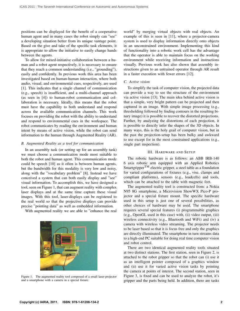
In an assembly task (or setting up for an assembly task)we must choose a communication mode most suitable toboth the robot and human agent. This communication modecould be speech [10] as it often is between human agents,but the bandwidth for this modality is very low and noisy,along with the ”vocabulary problem” [8]. Instead we haveconceived a system that can both easily display and ”see”visual information. To accomplish this, we have designed atool, seen on Figure 1, that can augment reality with complexlaser displays and at the same time capture these visualimages. With this tool, laser-displays can be registered tothe real world so that the projective displays can provideprecise ”pointing data” as well as embedded information.
With augmented reality we are able to ”enhance the real
Figure 1. The augmented reality tool composed of a small laser-projectorand a smartphone with a camera in a special fixture.
world” by merging virtual objects with real objects. Anexample of this is seen in [11], where a projector-camerasystem is used to display information directly onto objectsin an unconstrained environment. Implementing this kindof functionality into a robotic work cell has the advantagethat the operator is able to maintain focus on the workingenvironment while receiving information and instructionsvisually. Previous work has also shown that assembly in-structions given to an untrained operator through AR resultin a faster execution with fewer errors [12].
C. Active vision
To simplify the task of computer vision, the projected datacan provide a way to see the structure of the environmentvia active vision [13]. The main idea behind active vision isthat a simple, very bright pattern can be projected and thencaptured in an image. With simple image processing (e.g.,thresholding followed by finding contours in the resulting bi-nary image) it is possible to recover the distorted projections.Further, by analyzing the distortions of each projection, itis possible to directly infer the shapes of the 3D objects. Inmany ways, this is the holy grail of computer vision, but inthe past the projection-setup has been bulky and awkwardto use except for in the most constrained applications (e.g.,single part inspection).
III. HARDWARE AND SETUP
The robotic hardware is as follows: an ABB IRB-1406 axis robotic arm equipped with an Applied RoboticsSmartgripperTM electric gripper, a steel table as a foundationfor varied configurations of fixtures (e.g., vise. clamps andcompliant platforms), sensors (e.g., loadcells) and tools,which can be attached to the table with magnetic feet.
The augmented reality tool is constructed from: a NokiaN95 8G smartphone, a Microvision ShowWX Pico-P pro-jector and a special fixture mount. The specific hardwareused in this setup is just one of several possibilities, asother choices of hardware may be used. The smartphonerequires several special features (i) programmable graphics(e.g., OpenGL used in this case) with, (ii) video output, (iii)wireless connectivity (e.g., Bluetooth and WiFi) and (iv) acamera with wireless video streaming. The projector needsto be laser based so that it is focus free and only the graphicsare directly illuminated. The smartphone in turn streams datato a high-end PC suitable for doing real time computer visionand robot control.
There are two identical augmented reality tools situatedat two distinct stations. The first station, seen in Figure 2, isattached to the robot gripper so that the robot can (i) use itas an intelligent pointer composed of a graphics windowand (ii) use it for varied active vision tasks by pointingthe camera at points of interest. The second station, seen inFigure 3, is fixed and can be used to analyze the robot, it’sgripper and the parts being held. In addition, there are tasks
2
ICAS 2011 : The Seventh International Conference on Autonomic and Autonomous Systems
Copyright (c) IARIA, 2011. ISBN: 978-1-61208-134-2

Gripper direction
Cam
era
dire
ctio
n
Projector direction
AV InputAV Output Mounting surface�����������������
Elec
tron
ic g
ripp
er
ShowWX projectorNokia N95
Figure 2. The AR tool assembled with the electric gripper for mountingon the robot end-effector.
that depend on projecting from one vantage point, whileimaging from another (e.g., tasks involving triangulation) sofor these tasks both stations work together.
There is a data command loop that operates between theworkstation controller and the augmented reality tool. Thetypical steps for this command cycle are as follows:
1) Workstation: Send a high-level graphics command tothe phone based on the application.
2) Phone: Receive draw command from the workstation.3) Phone: Draw relevant pattern on phone’s screen.4) Phone: Project pattern on world.5) Phone: Snap a picture of the resulting projection.6) Phone: Send picture back to workstation.7) Workstation: Analyze image and extract information.8) Workstation: Send (optional) key information to phone
- projector to be seen by human agent. This informa-tion can be registered on objects in the real worldbased on image analysis.
IV. APPLICATION AREAS FOR HRI IN SEMI-AUTOMATEDSETUPS
There are many application areas for automated assemblywhere both human and robot agents can effectively coop-erate. These include (i) cooperative setups where many ele-ments are not suited to robot handling (ii) human training ofassembly methods and sequences (iii) robotic programmingby demonstrations (iv) and success or failure determinationin a given assembly step [14]. In an attempt to capture allof these possible applications, we have composed a generalframework, illustrated in Figure 4. If needed, the humanagent is able to perform some offline planning of robottasks, environment, etc. These plans are then ”mapped” tothe robotic work cell where they are put into reality throughthe two AR stations described. Reversely, the robot may
Nokia N95 Magnetic base
ShowWX projector
Opt
ical
Pos
t
Nokia AV-cableC
amer
a di
rect
ion
Proj
ecto
r dir
ectio
n
Figure 3. The AR tool mounted on a pair of optical posts for easyadjustments. The station can be conveniently placed by utilizing a magneticbase.
send information read from the environment through activevision back to the offline plan.
V. DETAILED APPLICATIONS
To demonstrate the general framework, we will presenttwo applications that use multi-initiative execution of setups.
A. Positioning fixtures in robotic environment
The first application involves the precise positioning ofmagnetic feet on a steel table. These magnetic feet secure
Cam
Offline plan
Mapping between virtual & real environment
Human Robot Interaction by Augmented Reality
Cam
Figure 4. A general concept sketch for using augmented reality in partiallyautomated assembly.
3
ICAS 2011 : The Seventh International Conference on Autonomic and Autonomous Systems
Copyright (c) IARIA, 2011. ISBN: 978-1-61208-134-2
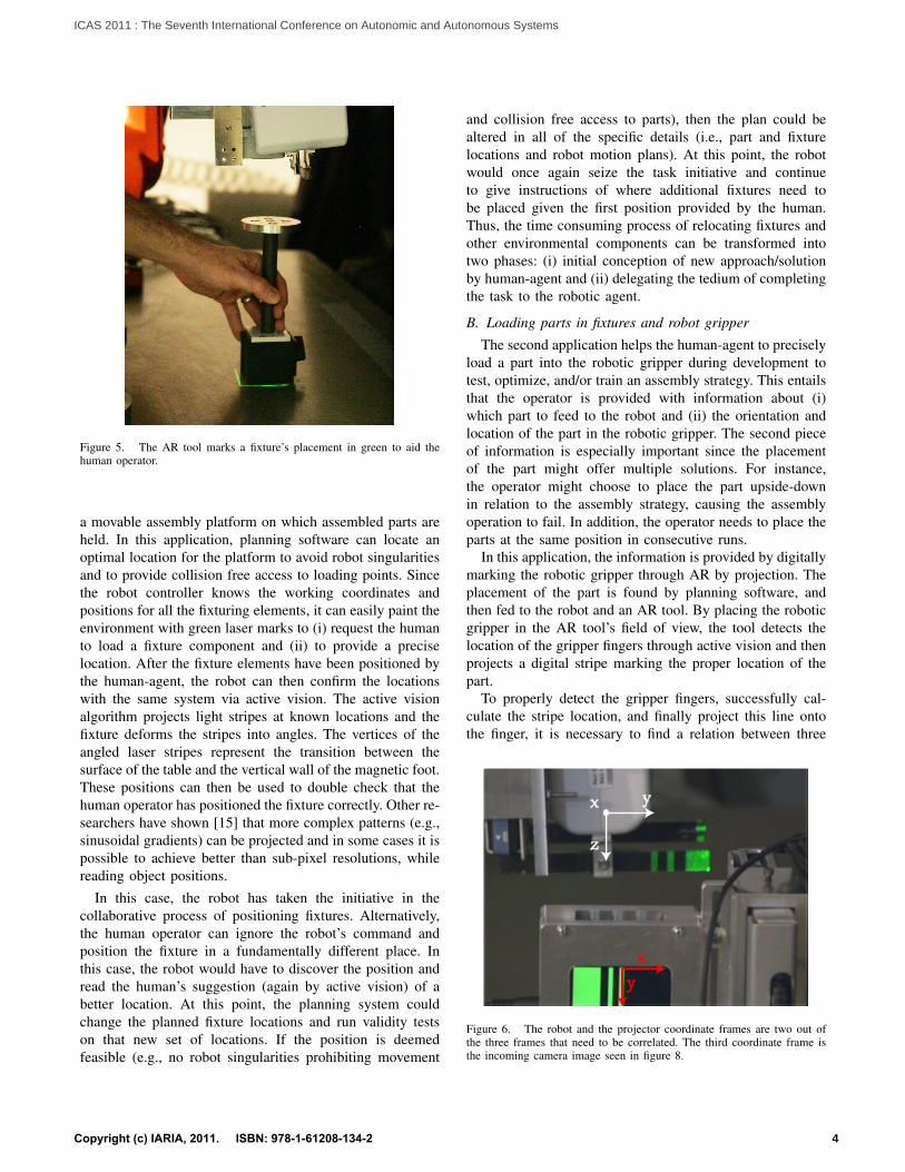
Figure 5. The AR tool marks a fixture’s placement in green to aid thehuman operator.
a movable assembly platform on which assembled parts areheld. In this application, planning software can locate anoptimal location for the platform to avoid robot singularitiesand to provide collision free access to loading points. Sincethe robot controller knows the working coordinates andpositions for all the fixturing elements, it can easily paint theenvironment with green laser marks to (i) request the humanto load a fixture component and (ii) to provide a preciselocation. After the fixture elements have been positioned bythe human-agent, the robot can then confirm the locationswith the same system via active vision. The active visionalgorithm projects light stripes at known locations and thefixture deforms the stripes into angles. The vertices of theangled laser stripes represent the transition between thesurface of the table and the vertical wall of the magnetic foot.These positions can then be used to double check that thehuman operator has positioned the fixture correctly. Other re-searchers have shown [15] that more complex patterns (e.g.,sinusoidal gradients) can be projected and in some cases it ispossible to achieve better than sub-pixel resolutions, whilereading object positions.
In this case, the robot has taken the initiative in thecollaborative process of positioning fixtures. Alternatively,the human operator can ignore the robot’s command andposition the fixture in a fundamentally different place. Inthis case, the robot would have to discover the position andread the human’s suggestion (again by active vision) of abetter location. At this point, the planning system couldchange the planned fixture locations and run validity testson that new set of locations. If the position is deemedfeasible (e.g., no robot singularities prohibiting movement
and collision free access to parts), then the plan could bealtered in all of the specific details (i.e., part and fixturelocations and robot motion plans). At this point, the robotwould once again seize the task initiative and continueto give instructions of where additional fixtures need tobe placed given the first position provided by the human.Thus, the time consuming process of relocating fixtures andother environmental components can be transformed intotwo phases: (i) initial conception of new approach/solutionby human-agent and (ii) delegating the tedium of completingthe task to the robotic agent.
B. Loading parts in fixtures and robot gripper
The second application helps the human-agent to preciselyload a part into the robotic gripper during development totest, optimize, and/or train an assembly strategy. This entailsthat the operator is provided with information about (i)which part to feed to the robot and (ii) the orientation andlocation of the part in the robotic gripper. The second pieceof information is especially important since the placementof the part might offer multiple solutions. For instance,the operator might choose to place the part upside-downin relation to the assembly strategy, causing the assemblyoperation to fail. In addition, the operator needs to place theparts at the same position in consecutive runs.
In this application, the information is provided by digitallymarking the robotic gripper through AR by projection. Theplacement of the part is found by planning software, andthen fed to the robot and an AR tool. By placing the roboticgripper in the AR tool’s field of view, the tool detects thelocation of the gripper fingers through active vision and thenprojects a digital stripe marking the proper location of thepart.
To properly detect the gripper fingers, successfully cal-culate the stripe location, and finally project this line ontothe finger, it is necessary to find a relation between three
xy
y
z
x
Figure 6. The robot and the projector coordinate frames are two out ofthe three frames that need to be correlated. The third coordinate frame isthe incoming camera image seen in figure 8.
4
ICAS 2011 : The Seventh International Conference on Autonomic and Autonomous Systems
Copyright (c) IARIA, 2011. ISBN: 978-1-61208-134-2

x = 0x = 20GL GL
y
x
(a)
y = 0GL
(b)
Figure 7. These patterns are used to detect the gripper fingers and tocorrelate the three coordinate frames.
coordinate frames: (i) The robot frame and (ii) the projectorimage frame, as illustrated in Figure 6, and finally (iii) thecamera image frame as seen Figure 8. To find this relationwe utilize the patterns shown in Figure 7.
The relation between the camera image and projectorimage coordinate frames is found by relating the knownpixel positions of the thin lines of the pattern in Figure 7(a)to the distance between the corresponding lines found inthe camera image seen in Figure 8. Note that the projectedpattern, seen in Figure 8, is rotated by 180 degrees as aresult of the projector orientation. The relation to the robotcoordinate frame is found by moving the gripper fingers intothe path of the projected patterns in the horizontal (Figure7(a)) and vertical (Figure 7(b)) directions respectively, untilthey are successfully detected in the camera image. Thus,the complete relation between the three coordinate framesare found in the following steps:
1) The pattern shown in Figure 7(a) is projected.2) The robotic gripper is moved horizontally into the
path of the projected pattern until the full pattern isrecognized (as shown in Figure 8) in the resultingcamera image.
3) The pattern is changed to the one shown in Figure7(b), and step 2 is repeated in the vertical direction.
4) The resulting robot position is saved, and the stripeis calculated from two captured images showing thetwo projected patterns respectively, yielding the resultshown in Figure 8.
5) A line is created based on the calculation and projectedonto the gripper (left-most stripe in Figure 8).
Once the stripe has been successfully calculated and pro-jected, the operator is able to load the part into the roboticgripper at the marked position.
In this application, the robot also takes the initiative,telling the human agent which part to load, and how toplace it. As previously discussed, it might be possible for
Figure 8. The result after image processing, which shows the calculatedgreen stripe (left most) for part placement.
the operator to load the part in several different orientationsand locations. This raises the possibility that the operatormisinterprets the information, or choose to ignore it, andas a result loads the part incorrectly. Thus, the robot needsto have the ability to check that the part has been loadedcorrectly, and perform a suitable correcting action in case itis not. This could involve requesting the operator to correctthe mistake, or, if possible, change the motion plan accordingto the loaded configuration of the part.
This application highlights a new design component forthis approach; namely, we often must design different pro-jected patterns for different applications. In this application,a 3 stripe pattern was chosen to simplify visual identificationof the green stripes and its subsequent processing to deter-mine positional information along the gripper fingers. Wealso have experimented with the mixing of primary colorsto compose different information in the same space duringprojection. Once visual processing begins, the color channelscan be separated and processed individually. The primaryadvantage of this approach is to allow one picture to encodeseveral different messages simultaneously, while noting thatsending pictures from the AR tool back to the workstationis a key processing bottleneck. Other well known patternsinclude a checkerboard pattern to calibrate the projection-camera system and sinusoidal wave patterns to achieve sub-pixel point cloud reconstructions. We fully expect that othernew applications will demand new and creative projectionsto help manage and minimize the effect of characteristiclimitations found in these applications.
VI. FUTURE WORK
We have discussed several applications with relativelysimple steps performed by the human and robot agents. Asthe applications become more complex, it will be necessaryto have dialog markers to determine when one step in anapplication ends and the next step begins. To seamlesslyswitch initiative between agents also requires clear dialogmarkers to avoid confusion or a time consuming end-of-stepconfirmation process. For example, in our first application
5
ICAS 2011 : The Seventh International Conference on Autonomic and Autonomous Systems
Copyright (c) IARIA, 2011. ISBN: 978-1-61208-134-2

we described a system where a person is directed to placea fixture at a given location, but they may choose to placeit someplace entirely different. In that case, the robot wouldhave to attempt to confirm the given placement and explicitlyfail. This failure mode in itself is the dialog marker thatallows the systems to swap initiative. However, this is notthe most efficient method. One option might be to provide asimple visual marker (or coin) painted red on one side andgreen on the other. By flipping the coin, the human operatorcan either seize or relinquish the initiative. Of course, it ispossible to do this process digitally (computer input), butthat may require accessing a teach pendant or computerinterface that would be relatively inconvenient. In addition,humans find speech to be the modality of choice especiallywhen only dialog markers are required [7]. In the end, weneed to find a method that does not impede progress in agiven task and is more resistant to background noise.
The augmented reality tool we have described in thispaper is ideal for tasks that require a narrow field of view.Unfortunately, that fails to address many applications thatrequire a wide-field of view with less precision. For example,if we wished to monitor the movements of the humanoperators for safety analysis, then a different device suchas the new Microsoft Kinect would be required.
Finally to achieve acceptance in the world of manufac-turing, it is necessary to do a carefully controlled studycomparing times and costs between these methods and thestate-of-the-art.
VII. CONCLUSION
The rapid miniaturization of key components: full colorlaser projection, wireless computing and video streamingwill make a wide array of augmented reality tasks feasible.By adding these functions to automated robotic systems,it also becomes apparent how humans and robots can col-laborate on complex tasks without excessive programmingoverhead. This is particularly important in manufacturingwhere the time to setup machines is becoming a dominantbottleneck in production due to smaller and smaller batchesand shorter product life-cycles.
ACKNOWLEDGMENT
We would like to thank Michael Dawson-Haggerty for hisdevelopment work to guide the placement of fixtures. Wewould also like to thank Otto Moensteds Fond, Knud Hoe-jgaards Fond, Oticon Fonden, Vilhelm Pedersen & HustrusLegat and Aalborg Stiftidenes Fond for the financial supportfor Dan Gadensgaard during the period of this project.
Finally, we would like to thank ABB Corporate Re-search for their partial support of the entire project. ThomasFuhlbrigge (ABB) and Gregory Rossano (ABB) both pro-vided significant feedback during the work.
REFERENCES
[1] S. A. Green, M. Billinghurst, X. Chen and J. Chase, ”Human-Robot Collaboration: A literature review and Augmented Re-ality approach in design,” International Journal of AdvancedRobotic Systems, Volume 5, 2008, pp. 1-18.
[2] J. Kruger, T. K. Lien, and A. Verl, ”Cooperation of human andmachines in assembly lines,” CIRP Annuals - ManufacturingTechnology, Volume 58, 2009, pp. 628-646.
[3] F. Walhoff, J. Blume, A. Bannat, W. Rosel, C. Lenz, andA. Knoll, ”A skill based approach towards hybrid assembly,”Advanced Engineering Informatics, Volume 24, 2010, pp.329-339.
[4] M. Zaeh and W. Roesel, ”Safety aspects in a Human-RobotInteraction scenario: A human worker is co-operating withan industrial robot,” in Progress in Robotics, Springer BerlinHeidelberg, 2009, pp. 53-62.
[5] J. A. Corrales, F. A. Candelas, and F. Torres, ”Safe Human-Robot Interaction based on dynamic sphere-swept line bound-ing volumes,” Robotics and Computer-Integrated Manufac-turing, Volume 27, 2011, pp. 177-187.
[6] N. Lauzier and C. Gosselin, ”3-DOF cartesian force limitingdevice based on the delta architechture for safe physicalHuman-Robot Interaction,” in IEEE International Conferenceon Robotics and Automation (ICRA 2010), May 3-8 2010,Anchorage, Alaska, USA, pp. 3420-3425.
[7] M. Lohse (2011, Jan. 6), ”The role of expectations inHRI,” in AISB’08 Workshop on New Frontiers in Human-Robot Interaction, 2009, Edinburgh, UK [Online]. Avail-able: http://www.aisb.org.uk/convention/aisb09/Proceedings-/NEWFRONTIERS/FILES/LohseM.pdf
[8] G. W. Furnas, T. K. Landauer, L. M. Gomez, and S. T.Dumais, ”The vocabulary problem in human-system commu-nication,” Commun. ACM, Volume 30, 1987, pp. 964-971.
[9] J. Peltason, F. H. K. Siepmann, T. P. Spexard, B. Wrede,M. Hanheide, and E. A. Topp, ”Mixed-Initiative in humanaugmented mapping,” in IEEE International Conference onRobotics and Automation (ICRA 09), May 12-17 2009, Kobe,Japan, pp. 2146 - 2153.
[10] I. Lutkebohle, J. Peltason, R. Haschke, B. Wrede, andS. Wachsmuth (2011, Jan. 8), ”The curious robot learns grasp-ing in multi-modal interaction,” in IEEE International Confer-ence on Robotics and Automation (ICRA 2010), May 3-8, An-chorage, Alaska [Online]. Available: http://aiweb.techfak.uni-bielefeld.de/files/cr-video.pdf
[11] D. Molyneaux, H. Gellersen, G. Kortuem, and B. Schiele,”Cooperative augmentation of smart objects with projector-camera systems,” UbiComp 2007: Ubiquitous Computing,Springer Berlin / Heidelberg, 2007, pp. 501-518.
[12] A. Tang, C. Owen, F. Biocca, and W. M. Mou, ”Performanceevaluation of augmented reality for direct assembly,” in Vir-tual and Augmented Reality Applications in Manufacturing,Springer, 2004, pp. 311-331.
[13] B. Zhang, E. J. Gonzalez-Galvan, J. Batsche, and S. Skaar,”Computer Vision” published by I-Tech, Vienna Austria,November 2008, pp. 111-123.
[14] A. Rodriguez, D. Bourne, M. Mason, G. Rossano, andJ. Wang, ”Failure detection in assembly: Force signatureanalysis,” in IEEE Conference on Automation Science andEngineering (CASE 2010), August 21-24, Toronto Canada,pp. 210-215.
[15] T. Peng and S. K. Gupta, ”Model and algorithms for pointcloud construction using digital projection patterns”, Trans-actions of ASME, Volume 7, 2007, pp. 372-381.
6
ICAS 2011 : The Seventh International Conference on Autonomic and Autonomous Systems
Copyright (c) IARIA, 2011. ISBN: 978-1-61208-134-2